Unstabilized HeNe lasers - the more conventional type that most people are familiar with from Physics 101 - are covered in the chapter: Commercial HeNe Lasers.
For current production lasers, the manufacturers' Web sites often provide basic specifications. A Google search is usually the easiest way to find them, but most are also linked from the chapter: Laser and Parts Sources. For older lasers, it's often difficult to obtain detailed specs so estimates based on physical size, and then testing may be the only option.
Much more information on stabilized HeNe lasers and typical locking schemes can be found in the chapter: Stabilized Helium-Neon Lasers.
And dimensions:
Nearly every model of stabilized HeNe laser ever sold commercially is listed in the chart below. Many are described in separate sections of this chapter, arranged approximately in alphabetical order by manufacturer. For these, the level of detail here is probably several orders of magnitude greater than from any other source, except perhaps the operation and service manual for the laser (which with few exceptions, is generally not available in the public domain). Where there is no entry for a particular laser, a Google search using the manufacturer (with or without model number) will usually locate what little information is available. Sometimes, a research paper referencing the specific laser will even have the most information!
Unless otherwise noted (below), these data were obtained from manufacturers' Web sites, brochures, spec sheets, or user manuals for each laser. Contributions (including stabilized HeNe lasers I've missed) and corrections are welcome. Please contact me via the Sci.Electronics.Repair FAQ Email Links Page.
All stability values are in parts per billion (ppb). For reference, 1 ppb is approximately 474 kHz or 0.000633 pm.
                                     <--- Frequency Stability Time Scale --->
    Model                    Type/AP  Sec    Min   Hour    Day   Year    Life
-------------------------------------------------------------------------------
  Aerotech DF170               AZ M                 ±2  ±2 (8 hr) ±20 (1 mo)
 *Aerotech LZR2000 (20)        SM M                 ±2            ±20 (1 mo)
 +Aerotech LZR3000 (20)        SM M                 ±2            ±20 (1 mo)
  Aerotech OEM05SF/105SF       SM S                 ±2  ±2 (8 hr) ±20 (1 mo)
  Aerotech OEM05SFX/105SFX     SM S                 ±2  ±2 (8 hr) ±20 (1 mo)
  Aerotech OEM1SF/110SF        SM S                 ±2  ±2 (8 hr) ±20 (1 mo)
 *Aerotech S100 (2)            SM S          ±1     ±2  ±3 (8 hrs)
  API XD Laser                 SM M     ±200 (unspecified time)
 *Axsys 150 (8)                DM M   ±2     ±6            ±20
  CDHC-Optics DH-HN250P        SM S
 *Coherent 200                 DM S          ±2 (5 min)          ±10 (long)
 *Excel 1001A/B/F              AZ M        20 (unspecified time)
  Feanor LN 10                 DM M                 ±1                   ±80
  Feanor LP 30                 AZ M                 ±2                   ±20
  Feanor LSP 30                AZ M                 ±2                   ±20
 +Frazier 100 (21)             I2 S                                     ±0.01
 *General Dynamics 150 (8)     DM M   ±2     ±6            ±20
 *HP-5500A/B/C, 5501A/B        AZ M                        ±2            ±20
 *HP/Agilent 5517 (all)        AZ M                        ±2            ±20
 *HP/Agilent 5518A, 5519A/B    AZ M                        ±2            ±20
 *HP/Agilent Z4214A (22)       AZ M          ±5 (5 min)
 *HP/Agilent N1211A (23)       AZ M          ±5 (5 min)
  JDS Uniphase 1410-1 (25)     DM S          ±0.05 (???)
  JDS Uniphase 1410-2 (25)     DM S          ±0.05 (???)
  JDS Uniphase 1420 (25)       DM S          ±0.05 (???)
  JENAer ZL 600 (10)           DM M                2.0                    20
  JENAer ZL 700 (10)           DM M                2.0                    20
  JENAer ZL 800 (10)           DM M                2.0                    20
 *Lab for Science 200          DM S  0.03   0.05   0.2     0.5
 *Lab for Science 210          DM S  0.03   0.05   0.2     0.5
 *Lab for Science 220          TZ S  0.01   0.02   0.05    0.2
 *Lab for Science 260          TM S  0.02   0.02   0.1     0.4
 *Laseangle RB-1 (3)           DM S  0.01   0.1
  Lasertex Frequency Standard  I2 S   ±0.001 (10 s)                    ±0.025
  Lasertex HPI-3D              SM M   ±1 (short term)                    ±1
  Lasertex LL 10               DM M   ±2 (short term)                    ±30
  Lasertex LS 10               DM M   ±2 (short term)                    ±30
  Lasertex LSP 30              AZ M   ±2 (short term)                    ±20
  Laser Metric Systems SFL-1   DM M         2 (unspecified time)
  Limtek LS 10.3               GP M        20 (unspecified time)
  LINOS FS Series              DM S          ±2     ±10    ±20
  LINOS FAS Series             DM S          ±1     ±2     ±10
 *Mark-Tech 7900               DM M                        ±2 (const. temp.)
  Mark-Tech 7910 (6)           DM M                        ±2 (const. temp.)
 *Melles Griot STP-901 (4)     DM S          ±1     ±4     ±6 (8 hrs)
 *Melles Griot STP-909/911 (2) SM S          ±1     ±2     ±3 (8 hrs)
 *Melles Griot STP-910/912 (2) SM S          ±1     ±2     ±3 (8 hrs)
 *Micro-g LaCoste ML-1         DM S  0.2 (10 ms)          1.6 (const. temp.)
 *Motion X (8)                 DM M   ±2     ±6            ±20 (24 hrs)
  NEOARK NEO-262               TZ M          1 (unspecified time)
  NEOARK 430 (11)              DM S         30 (unspecified time)
  NEOARK 430-R4 IR (11)        LD S         50 (unspecified time)
  NEOARK NEO-9111   (11)       AZ S                 1     10 (1 wk)
  NEOARK NEO-92SI-NF (11)      I2 S                                     0.025
  NEOARK NEO-OL101K (11)       OL S  0.0001 (10 seconds)
  NEOARK NEO-2MSS (11)         PS S
  NEOARK NEO-5MSS (11)         PS S
 *Newport NL-1 (3)             DM S  0.01   0.1
 *Nikon NKL-85 (14)            LD S
  Nikon NN-1                   I2 S
 *NIST ISHL                    I2 S
  NPL Hexagon (13)             ?? S               0.01                   ± 2
  NPL I2 543 nm                I2 S                                      ± 0.25
  NPL I2 633 nm                I2 S                                      ± 0.2
  Optodyne L-103               ?? M
  Optodyne L-104               SM M
 *Optodyne L-109               DM M
 *Optra Optralite              AZ M
 *Pacific LaserTec STP-910 (2) SM S          ±1     ±2     ±3 (8 hrs)
 *Pacific LaserTec STP-912 (2) SM S          ±1     ±2     ±3 (8 hrs)
 *Perkin Elmer 5800            LD S
 +PLASMA LGN-212               AZ M         10 (unspecified time)
 +PLASMA LGN-302               DM S         10 (unspecified time)
 +PLASMA LGN-303               DM S         10 (unspecified time)
 +PLASMA LGN-304               DM S         10 (unspecified time)
 +Renishaw HS10                DM M       ±100 (unspecified time)
 +Renishaw ML10                DM M                 ±20          ±50
 +Renishaw RLU10 (24)          DM M          ±10    ±50    ±50   ±100
 +Renishaw RLU20 (24)          DM M          ±1     ±2     ±10   ±100
 +Renishaw XL80                DM M       ±50 (unspecified time)
 *REO 32734                    DM S          ±2     ±2     ±4 (8 hrs)
 *REO 33099                    DM S          ±2     ±2     ±4 (8 hrs)
 *REO 39727                    DM S          ±2     ±2     ±4 (8 hrs)
 *REO R14286                   DM S          ±2     ±2     ±4 (8 hrs)
 *SIOS SL 02                   DM S          ±2     ±10    ±20
  SIOS SL 03                   DM S          ±1     ±2     ±10
  SIOS SL 04                   DM S          ±2     ±10    ±20
 *Spectra-Physics 117 (5)      DM S
 *Spectra-Physics 117A (4)     DM S          ±1     ±4     ±6 (8 hrs)
 *Spectra-Physics 117B (5)     DM S          ±1     ±4     ±6 (8 hrs)
 *Spectra-Physics 117C (5)     DM S          ±1     ±4     ±6 (8 hrs)
 *Spectra-Physics 119 (7)      LD S                        ±2
 *Spindler and Hoyer ZL-150    AZ M
  Spindler and Hoyer ZL-1150   AZ M
 *Teletrac 150-IV (8)          DM M
 *Teletrac 150 (Long) (8)      DM M   ±2     ±6            ±20 (24 hrs)
 *Teletrac 150 (Short) (8)     DM M   ±2     ±6            ±20 (24 hrs)
 *Teletrac 150 (Long) (8)      AZ M   ±2     ±6            ±20 (24 hrs)
 *Thorlabs HRS015 (19)         DM S          ±2     ±2     ±4 (8 hours)
 *Thorlabs HRS015B (19)        DM S          ±2     ±2     ±4 (8 hours)
 *Tropel 100 (15)              DM S
 *Tropel 200 (15)              DM S          ±2 (5 min)           ±10 (long)
  Uniphase 1220 (16)           DM ?
  VM-TIM LHN-212-1 (18)        AZ M                        ±10 (8 hrs)
  VM-TIM LHN-303               DM S                        ±10 (8 hrs)
  VM-TIM LHN-220SF (18)        ?? S                        ±10 (8 hrs)
 *Wavetronics WT307 (all) (17) AZ M                        ±2            ±20
  Winters 100                  I2 S                                     0.025
  Winters 200 (12)             I2 S                                     0.025
 *Zygo Axiom 2/20 (9)          DM M                 ±2     ±10   ±100
 *Zygo 7701/7702 (9)           DM M                 ±2     ±10   ±100
 *Zygo 7705 (9)                AZ M                 ±10    ±20   ±200
 *Zygo 7712/7714 (9)           DM M                 ±0.5   ±1
 *Zygo 7722/7724 (9)           DM M                 ±0.5                 ±10
The "*" denotes lasers that are covered in detail elsewhere in this chapter, usually including tests and photos. "+" denotes lasers that are described but not tested - yet.
Type Legend:
AP (Application) Legend:
A metrology laser can generally also be used for scientific/research applications since all have very tightly controlled optical frequency. And while the converse is often (but not always) true in principle, it's not usually practical or worthwhile except for experimental purposes since metrology systems may require laser characteristics (like two-frequency) that aren't present in laboratory stabilized lasers. In addition, the optics and cabling/electronics requirements would likely make their adaptation potentially complex, if possible at all.
Notes:
Pacific LaserTec acquired all of the Melles Griot HeNe assets including the production line and personnel. They continue to offer the STP-910 and -912 (and probably the other variations on the STP-910 and -912 but NOT the -901. Tubes for Zeeman lasers with split frequencies beyond 5 MHz are also available.
I know of only one version of the Axsys/General Dynamics 150 laser. It outputs a circularly polarized beam and uses a PIC-based controller. But other variations may be available.
For these lasers, Teletrac went to Axsys which went to General Dynamics. This technology is now provided by Motion X (2015).
Due to the similarity to the Teletrac lasers, Axsys info is lumped in with Teletrac.
Among commercial instruments, the Coherent LaserCheck and Sper Scientific 840011 are convenient and relatively low cost. However, for observing the warmup and locking behavior of stabilized lasers, a power meter with graphing capability or a data acquisition system (possibly multi-channel) may be desirable.
Commercial SFPIs are available (though not as many as in years gone by). Suppliers include Ophir and Thorlabs. Expect to spend $2,500 or more. However, it's possible to build an SFPI capable of easily checking for SLM operation of stabilized HeNe lasers (as well as doing a lot more) for under $100 (excluding the required oscilloscope). See the sections starting with: Scanning Fabry-Perot Interferometers.
The simplest tests would be to monitor the output (or orthogonal polarizations if both are present) for a few hours with a recording laser power meter or photodiode and data acquisition system. If high frequency noise is a concern, use a fast photodiode and RF spectrum analyzer to search for residual ripple from the HeNe laser power supply and PZT/heater driver making its way into the output.
While there is usually an optical frequency specification for stabilized HeNe lasers, most are not very precise because electronic adjustments and use can affect it by 10s of MHz.
For the metrology lasers from HP/Agilent/Keysight, the optical frequency is a solid specification and most reasonably healthy samples will be within ±10 MHz of the precise value to at least 8 significant figures. Therefore, such a laser makes a decent relatively low cost optical frequency reference. Even though they output consists of two optical frequencies, they are close together (usually less than 4 MHz) and one can be singled out with a polarizer if desired. Suitable guaranteed working lasers of this type can be found on eBay for under $1,000.
However, to determine the optical frequency to 10 or 11 significant figures requires an iodine-stabilized HeNe. If you have to ask what that is, you definitely can't afford one. ;-) However, it may be possible to send a laser out to a standards agency like NIST to get its optical frequency measured. (It is believed that Keysight does not actually do this for their so-called "Calibration" report, but only confirms output power and split frequency are within spec for the laser model.)
When making measurements on the output of most lasers, but particularly stabilized HeNe lasers, whether using a power meter, Scanning Fabry Perot Interferometer (SFPI), or another test instrument, care must be taken to avoid back-reflections into the laser that may, well, destabilize it. With some, even slight contamination on the surface of the output mirror, or a piece of clear tape over the output aperture will cause lock to be lost resulting in random fluctuations in output power and/or optical frequency. With most of these, no harm is generally done, but they would then more appropriately need to be called destabilized lasers. :-)
The gas fill ratio for neon of 20Ne to 22Ne affects both the absolute stability of optical frequency as well as immunity to back-reflections. Gas fills that are substantially single-isotope (including natural Ne which is approximately 9:1 for 20Ne and 22Ne, respectively) have a narrower gain bandwidth so that stabilization can be more effective, resulting in less susceptibility to drift in optical frequency. However, using an approximately equal ratio of the two isotopes may result in an increase in immunity to destabilization from back-reflections of 10 fold or more, which can be beneficial in interferometers where all back-reflections cannot be easily (or at least inexpensivly) suppressed. See U.S. Patent #6,865,211: Gas Laser and Optical System. Of course, users of these lasers have little control over the gas-fill. ;-)
If the above is too complex to even contemplate :), a basic laser power meter can be constructed from a photodiode, resistor, battery, and digital voltmeter (DMM or DPM). If available, the photodiode should have a diameter larger than the beams from the lasers to be measured, though smaller PDs could be used with appropriate fudge factors. :). A 9 V battery is most convenient and even a nearly dead one (5 or 6 V) will be fine as the exact voltage doesn't matter. The resistor provides the calibration such that the photo-current is converted to a voltage corresponding to the output power. Wire the components in series with the photodiode back-biased by the battery and measure across the resistor. For a typical silicon photodiode at 633 nm, the resistor will need to be between 2.5K and 4K ohms to result in a sensitivity of 1 V/mW. Replace the resistor with a trim-pot for precise calibration if desired. The back bias assures linearity up to a few mW, sufficient for any of these stabilized lasers.
   +5VDC
     o
     |         4.7K
     +---------/\/\-------+
     |                    |
     |         + DMM -    |
 +---+---+     |     |    /
 |       |     V     |    \ Zero
 | SS49E +---/\/\/\--+--->/ 1K
 |       |    Gain        \
 +---+---+    20K         |
     |                    |
     +--------/\/\--------+
    _|_       4.7K
     -
The sensor was installed in a pill bottle using non-ferrous "hardware" as seen in Photo of Sam's Super Simple Gauss Meter. Power is provided to the white 2 pin header from a regulated linear 5 VDC power supply; the output to a DMM is taken via the red and black wires off to the right. The "probe" can be easily inserted into HP/Agilent or other cylindrical magnets, or used outside of them for relative measurements. This is what's called an "axial center probe" since it is forced (by the pill bottle!) to be oriented such that it reads the axial field in the center of the magnet. Any transverse component of the field - which would be due to non-uniformity of the magnetization of the Alnico material is largely ignored since the active region in the laser tube's bore is very narrow. A sample of the sensor can be seen between the circuit and pill bottle.
Calibration was done using a carefully wound single layer 161 turn, 94 mm long electromagnet solenoid at 1 A, which works out to 21.5 g.
The gauss meter is perfect. :) But real World magnets are not. They are actually quite terrible in terms of field uniformity. For the typical HP/Agilent magnet, only the central 1/3rd or so is even reasonably constant with the field strength tapering off toward the ends. (Some actually increase slightly near the ends.) Yet, the active discharge in these lasers is often exactly the length of the magnet! And, the field strength may not be symmetric even well inside as these Alnico magnets can have large local variations either from the way they are manufactured, or from deliberate or accidental demagnetization. For example, simply rolling a 20 penny (~3 inch) steel nail around the outside will reduce the field inside by a few percent permanently. And much more extreme effects are possible by applying and removing Alnico or rare earth magnets. More on these effects in conjunction with HP/Agilent lasers, below.
Searching on eBay may turn up high price gargantuan machines for creating (or "charging") the magnetic field of Alnico, ceramic, and rare earth magnets. though most such searches return totally irrelevant results. And any that do show up are often untested (a synonym for "broken"), incomplete, or not suitable without additional effort or expense - or not at all - for modifying the field strength of the types of the magnets used in Zeeman lasers. A search on Google for "Alnico Magnet Charger" is a bit more successful with the first hit being for one of those gargantuan devices, the All Magnetics MC-8000 Series Magnetizer. It has the appearance of a dishwasher on wheels - which says something about its weight. The basic version is only $9,400 for the standard version, and there's a double strength option available. $9,400 just happens to be about the cost of a 5517 laser! So if it's a one shot (no pun) deal, just buy a new laser. ;-) But if you do by chance have access to one of those beasts, it may be suitable - at somewhere below its minimum setting. ;-)
The magnets in commercial Zeeman lasers are almost always made of Alnico (an alloy of iron which includes aluminum, nickel, cobalt, and possibly some other metals). It turns out that Alnico is among the easiest common magnetic material to deal with in terms of changing the magnetic field. Only a very few models of Zeeman lasers use ceramic or rare earth magnets. And none of these are likely to be of more than academic interest.
At first it never occurred to me that modifying the field of such a large magnet could be accomplished with a very simple device. Permanent magnets are, well, permanent, right? :) Based on experience with various soft magnetic materials or other magnets in contact with the Zeeman magnets, it's clear that reducing the field permanently is all too easy and often occurs accidentally. But increasing it? Digging into the actual requirements in terms of the necessary charging field magnitude for an Alnico magnet and electromagnetic solenoids, showed that it really wasn't that difficult. The only unknown was then how much energy would be required. It turns out not that much and is mostly just a matter of providing enough ampere-turns. So constructing a MacGyver-style magnet charger suitable for HP/Agilent (or other Alnico magnets of similar or smaller size) requires just a few commonly available electronic components and a spool of thick wire. The most time consuming part was winding the solenoid. It was literally only around 15 minutes to wire up a bridge rectifier and 2,000 µF capacitor bank and be able to change magnet field strength. For my initial tests, a Variac was used to adjust the voltage (and thus energy) and touching a pair of wires together discharged the capacitors into the coil with only minimal sparking, though doing this with even a relatively high current push button switch eventually resulted in the contacts tending to stick together. :( The voltage on the capacitors was increased in small steps and after each discharge the field was measured. Even at 1/4 voltage, a single pulse increased the field of a 220 G magnet by 10 G. At 1/2 voltage, the field increased to 350 G. So, it was clear that the range would be quite adequate. If boosting the magnetic field only needs to be done for one laser, nothing fancier is really required.
My slightly more refined version will charge most bare HP/Agilent magnets to 500 G or slightly higher, which is greater than the field used in any known 5517, 5501, or N1211A laser, though I've come across a few samples of HP magnets that won't go above about 325 G. This is probably due to a different formulation - e.g., Alnico 3 instead of Alnico 5. See:
It can, of course, also be used to reduce the field to any desired value down to 0 G or fully reverse the polarity. And as a bonus, it can magnetize screwdrivers! The total cost for this gizmo was $0.00 using all junk parts. Sorry about the ugly recycled HeNe laser power supply box. It was even uglier originally. :) The control to adjust pulse energy is a common light dimmer. This isn't ideal as there is hysteresis - a Variac would be better but more expensive (and heavier) if built-in, or a bench Variac could be used. A neon indicator shows that the unit is plugged into a live AC outlet. It is line-connected with no isolation, so this is a useful safety feature. The two yellow LEDs show when the dimmer is on and a rough indication of drive voltage. The red LED and digital panel meter display the capacitor voltage. And then there's the little silver FIRE button beneath it. ;-) The maximum energy is about 25 J at a voltage of 160 V from a pair of 1,000 µF electrolytic capacitors in parallel. An SCR discharges the capacitors into a 290 turn coil 8 inches in length wound with #14 stranded THHN building wire in 4 layers on a 2-1/4 inch I.D. cardboard form. A coil using magnet wire would be more compact but this wire was available and stranded wire is easier to wind by hand. ;-) To increase the field of HP magnets inserted with their arrow matching the arrow on the coil, the current should flow CCW when viewed from the front. The 8 inch length is to assure field uniformity in the center, though that is probably not required. At maximum energy, the field at the center on-axis inside most HP/Agilent magnets reaches between 480 and 550 G and some go higher, but there are a few exceptions as noted above. One shot usually brings the magnet to within a few percent of the target field strength.
Rough circuit diagrams for versions using Variacs are shown in Schematics for Sam's Basic and Dial-A-Field Alnico Magnet Chargers. The schematics are called "rough" because there are other minor differences and some part values may not match. For some reason I have no record of the actual circuit that was built. And I'm not going inside to figure it out. Can you believe that? Refer to the interior photo. ;-)
When designing these, the discharge should be critically damped or slightly over-damped to avoid a reversal of current which not only could reduce or negate any effect on the magnetic field but also put reverse voltage across the electrolytic capacitors - and that can be explosive. :( Since the damping factor will depend on what's inside the coil, a large reverse polarity ("free-wheeling") diode is present to prevent this. (The massive bridge rectifier visible in the photo was used only because it was available; Any diode rated at least 50 A and 400 V should be acceptable.) But if the discharge is too slow, it may not shut off if the pushbutton is released quickly. This was found to be true when pulsing a 100 W incandescent light bulb instead of the coil, used as a dummy load during testing. :) Its resistance when cold is around 10 ohms but becomes 100 ohms when hot, part way through the discharge. So the effective time constant can be close to seconds (2,000 µF x 100 ohms).
The driver SCR was included to assure a solid firing pulse for the main SCR. But it is probably unnecessary if the current through the FIRE switch is comfortably above the minimum Ig for the main SCR. Even with contact bounce, the initial pulse should be much longer than needed. The next version (below) does away with the driver SCR without problems. And if recharge time is not a concern, it should be possible to decrease the charge current enough so that interrupting it is not necessary to assure SCR cutoff. Even with only 200 ohms total in series with the bridge (as in the prototype), it was a close run thing with the SCR not shutting off consistently only near maximum input. With 1K ohms as in the schematic, it's probably fine, but will depend on the SCR specifications.
Originally, it had a small edge-view analog meter for capacitor voltage but (1) this wasn't high tech and (2) for unknown reasons the movement become sticky after awhile. Its replacement, a $1 DPM from eBay only reads to around 33 V max despite what the listing claimed. Can you believe that? :( ;-) (It's not broken, several others behave the same.) So, RCal is set so full scale is 30 which isn't as round a number as 100 (%) would be but it's just an arbitrary value anyhow. The only disadvantage of using a DPM is that it needs a separate power supply so the guts of a 12 VDC wall adapter that had mediocre regulation was stuffed inside the box. For this regulation doesn't matter as the DPM will run on 5-30 VDC. It could be powered from the SCR trigger supply but that would require some changes since the LED display draws up to 10 mA, which would be a problem especially at low output voltage. Alternatively, a 9 V battery could have been used.
While the photo shows a bare Agilent magnet, it is possible to remove the rear-end bracket ("foot") from the complete tube assembly in any of the lasers in the small cases and then slip the magnet butt-end first into the charging coil. For "Long" tube tube assemblies, a small amount of potting material would need to be cut away for the bracket to clear, but this can be done without affecting anything else and doesn't need to be replaced. But it's very easy to accidentally slice into the high voltage cable. Then it may arc when starting and need to be re-insulated. The fatter tube assemblies in the 5517A, 5518A, and 5519A/B are out of luck without significant and messy disassembly, but the likelihood of ever needing to boost their field is rather small.
The field uniformity at the end of the solenoid isn't as good as in the center, but is acceptable. This has been confirmed with an otherwise useless Agilent 5517C. Since only external measurements are possible with the glass tube inside the magnet, the exact field strength along the axis is not known. However, based on measurements with the sensor centered front-to-rear and against the magnet show that a similar range of adjustment is possible. Initially, the field measured 365 G. After partial demagnetization, it dropped to 135 G. And at full magnetization, was over 520 G. With the laser tube powered, the change in the split frequency was immediately apparent and there was no evidence of any damage to the tube. This is now done routinely to adjust split frequency when an increase is required. When reducing the field, only a tickle is needed - a few percent of maximum voltage on the capacitors. Multiple pulses can be used to incrementally reduce the field strength. Too much energy and the field will reverse polarity. Or if the magnet is inserted backwards during charging. After zapping a magnet, it is worth confirming that the field is still in the proper direction by bringing it near a known original magnet - they should repel when oriented the same way. The laser will not work properly if its field is the wrong polarity.
The only annoyance of the original implementation was that the magnet had to be removed from the coil and inserted in the opposite direction to change from magnetize to demagnetize, or vice-versa. So a BIG DPDT switch was added to reverse polarity and select charge or discharge (lower right of case in the photo). ;) It's only rated 20 A but that's when switching. The contacts have very low resistance when stationary. Less hassle and cost than an H-Bridge of SCRs. It works well enough.
Unfortunately, the magnet can't be fine tuned using the Dial-A-Field™ with the tube assembly installed in the laser. Perhaps a future coil design would solve this. :-) Or perhaps the electromagnet coil described in the next section could be used. However, for setting the field close to what is required, the laser tube can be powered while inside the charging coil. The heater voltage should be set to 5 or 6 V which is where it would be when locked. After thermal equilibrium is reached, the field can be adjusted while monitoring the Zeeman beat frequency with a scope and/or frequency counter using an HP 10780 optical receiver or biased photodiode like a Thorlabs DET110 behind a polarizer. Adjust the heater voltage slightly if mode sweep is stalled or takes too long. The effects of any change in magnetic field will be instantly obvious. The lock point would be in the center of the region of mode sweep where there is a beat. This is usually at the maximum frequency for higher-REF lasers like the 5517D, but may not be for lower ones like the 5517A or 5501B. If boosting the field, the output should also be monitored on a Scanning Fabry Perot Interferometer (SFPI) for rogue modes, which will always be present on either side of the strongest mode if the field goes too high. Below the rogue mode limit, there will be at least a short time when only the single Zeeman split mode is present. And if the field is boosted really high, the split gain curves may be pulled so far apart that there will be no beat at all. Set the field so the split frequency is slightly higher than required for the specific model laser - it can always be reduced.
But there doesn't appear to be any reason the pill bottle Gauss meter probe described in the previous section cannot remain in place inside the magnet inside the coil when it is zapped to monitor the progress of the field adjustment. :)
Finally (for now), a version was constructed upon the request of a major laser company for installation in a custom case with external Variac. So it's somewhat simpler than the one in the ugly box. ;-)
The schematic for this matches the actual device fairly closely except that the polarity reversing switch will be added later if needed. And as with the boxed version, the massive bridge rectifier was used for the free-wheeling diode only because it was available; Anything rated at least 50 A and 400 V should be acceptable.
As a side note in the trivial triviality department, it is theoretically possible to accidentally change the strength of the magnets in your expensive HiFi system loudspeakers by listening at really high volume. A rough calculation shows that for a small speaker driver using an Alnico magnet, a peak electrical power of around 1,000 watts may result in a permanent field change (about 1 millisecond before the voice coil vaporizes). :( :) Since modern speakers use more exotic ceramic or rare earth magnets with higher coercivity and a larger ratio of magnet to core area, somewhat more power will be required (like 10,000 or 100,000 or perhaps 1,000,000 W). But why take chances? Beyond preserving your hearing and relations with the neighbors, this is yet another reason to keep the decibels down. :-)
A summary can be found in the section: Sam's Full Range Variable Zeeman Electromagnet. And complete details should you wish to replicate this can be found in Universal Bipolar PWM Driver 1 Assembly Manual.
The Mini Laser Mode Analyzer (mLMA1) Version 2 with its LCD display can also be used as a frequency counter. But (1) its input is single-ended so the interface circuitry would need to be matched to the specific levels of one of the outputs of the 10780 or use a different interface and the usable upper limit is around 4.0 MHz due to its much slower microcomputer. And its frequency counter display is also very small and I have no plans to change that. ;-)
An inexpensive frequency counter or PCB could also be used. But it should be the type with an actual gated counter, not one based on down-conversion, which are sensitive to waveform shape. And the input may need to function with lower signal amplitudes than TTL provides. The one I tested is typically listed as "1Hz-50MHz Crystal Oscillator Frequency Counter Meter 5-Digital LED Display Kit", under $10 on eBay from USA sellers; under $5 from the Far East. For this application they tend to be a bit too smart for their (our) own good with auto-ranging that apparently cannot be disabled. So, as the beat frequency comes and goes, there will be instants where the gate will sample something in the kHz range and a totally bogus value is displayed in the wrong digits. If anyone can locate the firmware source code in C for these, I Ctould probably remedy that. The large red 7-segment LEDs also hark back to 1970s equipment. ;-) See Zeeman Frequency Counter using Low Cost Kit. A circular polarizer sheet over the display improves the contrast, especially for photos.
The benefit provided by the 10780 (as opposed to something like a biased or even conventional amplified photodiode) with either µMD2 or a low cost frequency counter is seamless operation with almost any two-frequency Zeeman HeNe laser without adjustments of any kind.
This rig may also be used to test for the second order beat in longer laser tubes that oscillate with at least 3 modes present during part of mode sweep. The frequency of the second order beat is typically in the hundreds of kHz range so the 10780 will respond to it. The (first order) beat between lasing modes which is in the hundreds of MHz range is well outside its bandwidth and is ignored. The orientation of random polarized tube should be adjusted so that its principle polarization axes are at 0/90 degrees so that the modes will be combined by the 10780's polarizer at 45 degrees. Linearly polarized can be at any orientation where enough optical power is passed by the 10780's polarizer.
With a single photodiode sampling the beam, only the amplitude of one of the two polarized modes can be stabilized. There are two beam-splitter cubes inside the adapter. The one closest to the laser tube is a common polarizing beam-splitter cube which diverts thee unwanted polarized mode into oblivion and only passes the desired one. The second diverts about 10 percent of the desired mode to a photodiode on the locking PCB. A second photodiode soldered to the locking PCB monitoring oblivion can be used to implement dual mode stabilization as I have confirmed.
Despite using only a single mode for feedback, the frequency stability will still be quite good once the laser tube has reached thermal equilibrium and its power has leveled off. As the tube ages and its power declines, the output power from the laser will remain constant until it approaches what's available from the HeNe laser tube. At that time, it will lose lock and may even be damaged, more below. With dual mode frequency stabilization, locking will still be possible even when the power output from the tube is very low because it is the difference of the polarized mode amplitudes that produces the error signal, not a specific value. In addition, with intensity stabilization, the frequency will drift as the tube gets weaker and the lock point moves with respect to the neon gain curve. (However, due to the shape of the gain curve for the tubes generally used with these lasers, the change in frequency will be minimal.) Nonetheles, why frequency stabilization was not implemented instead, or in addition to intensity stabilization as in the 05-STP-901, is a mystery as it would have been a very straightforward enhancement - primarily a second photodiode! Nearly everything else is already there, expecially in the newest Melles Griot version. More on this below.
Lasers based on the Aerotech technology are now sold as the Melles Griot STP1 with specific model numbers of 25-STP-910 and 25-STP-912. [They may also be found as 05-STP-910 and 05-STP-912. Whether "05" or "25" is used simply depends on if it is considered a component (05) or system (25), and sometimes at random!] There was also an 05-STP-914, now discontinued. It had an output power similar to that of an 05-STP-910, but a larger diameter beam with lower divergence. And as of early 2016, the -910 had also apparently been discontinued, with only the higher power -912 remaining. Then a few months later, it reappeared, possibly as a result of my analysis pointing out that due to the mode profile of the shorter -910 tube, it has better absolute frequency stability with respect to output power adjustment over its life. :) Or more likely due to complaints from unhappy customers requiring them as replacements in instruments like wavemeters.
The Melles Griot lasers are physically and functionally very similar to the Syncrolase 100 but both of these use a separate HeNe laser power supply instead of having one inside the laser head. (The Melles Griot 25-STP-909 and 25-STP-911 had the built-in power supply but have been discontinued.) While, it is not known how much the electronics differ compared to the S100 version, all indications are that very little has been changed since obtaining the technology as part of the acquisition of the HeNe laser division of Aerotech. Melles Griot calls them "frequency stabilized lasers" though the description indicates that the same amplitude stabilization technique as the Syncrolase is used (and examination of the locking adapters confirms that there is only a single photodiode). Interestingly, the latest Melles Griot locking adapter PCB has hooks for implementing full frequency stabilization, but to my knowledge, it has never been offered as a product and I'm the only one who has ever tested this feature :) More below.
Searching for "Melles Griot 25-STP-910" or "Melles Griot STP1" should return a description and spec sheet. Here is a summary of the specifications for the Melles Griot versions:
Note that based on the user manual, the power output range is NOT guaranteed, only the stated value (0.7 or 1.0 mW). It may be possible to order one with a guaranteed higher output but this has not been confirmed.
And, if you'd like to order a few, the Melles Griot price in 2012 was $4,388 each for the low power version (0.5 to 0.95 mW) and $4,662 each for the high power version (0.6 to 1.4 mW). I wonder how they came up with those especially round numbers for the prices. (As of 2018, Melles Griot is no longer in the HeNe business - period. Go figure.)
The output power is a user adjustment (a trim-pot) that sets the intensity stabilization point, and indirectly the operating frequency. In addition to versions based on output power, the Syncrolase came in two versions based on whether a pair of DC wall adapters were used to power an internal HeNe laser power supply and the locking controller, or whether the laser head had a standard Alden connector to attach to an external lab-style HeNe laser power supply, which is included in the price, along with the wall adapter for the locking controller! :) Now, why weren't the two combined, given the warning in the operation manual: "Application of power to the SFA adapter (locking controller) in excess of 5 minutes with the head de-energized may damage the SFA adapter". There's more on this below, though the Melles Griot version appears to have fixed this minor deficiency.
One of the unique features of this system is that rather than using a resistance heater over a substantial part of the HeNe laser tube as is done in most commercial stabilized HeNe lasers, these lasers use a compact "locking adapter" attached to the end of the laser head containing a coil surrounding only the OC mirror mount stem to directly heat the metal mount via RF induction. A very simple MOSFET driver can provide over 10 W directly to the mount resulting in a very rapid response. Based on tests I've done, I estimate that at maximum RF power, it will increase the temperature of the mirror mount stem itself by greater than 1 °C per second. This is more than an order of magnitude faster than traditional resistance heaters surrounding the glass portion of the tube. A temperature sensor in close proximity to the mirror mount stem senses its temperature and is used both to switch the feedback loop on when hot enough, as well as to shut the heater off if the temperature goes too high. Warmup to fully stable operation still takes 20 or 30 minutes because the rest of the laser head has to come into thermal equilibrium as well as the mirror mount stem. But, initial locking is very quick - typically 3 to 5 minutes. And once locked, it should use less power and be more immune to ambient temperature variations, and the faster response also improves frequency stability.
The same locking adapter may be used with any compatible laser head requiring at most minor electronic adjustments. In addition, the use of this technique allows for the possibility at least in principle of converting almost any HeNe laser tube with a suitable mode structure and cathode-end output into a stabilized laser by simply attaching the locking adapter. However, in practice, minor details like the mirror mount stem dimensions and the length of the exhaust tip-off prevent most common tubes from being used. For tubes with anode-end output, if sufficiently robust insulation could be added between the mirror mount stem (HV anode) and coil, they too would work without worrying about the exhaust tip-off.
The DC wall adapter (either version, 1 or 2 required depending on the model of the laser) is rated 13 VDC, 1.3 A. Measurements show it to have an open circuit output of 16.5 V. The plug is 5.5 mm/2.5 mm center positive. Since there is a 7812 +12 V regulator in the controller (see the schematic below), the output of that DC adapter must be greater than about 14.5 V to assure proper regulation. So, at least once the feedback loop is closed, the input voltage should never dip below 14.5 V. I do not know the official specifications for the external HeNe laser power supply (where required), but based on the length of the tube and other typical Aerotech tubes (and the supply that comes with an OEM version of the 05-STP-910), it is probably around 1,500 V at 4 mA.
That Melles Griot OEM version (typically found in some high-end wavelength meters as a reference) is otherwise identical to the normal one except that its output is fiber-coupled. One example is shown in Melles Griot Fiber-Coupled 05-STP-910 Stabilized HeNe Laser. There is an additional assembly that screws onto the output end of the laser (and is then glued) with a 4 position shutter which can be set to block the beam, pass it to the fiber, or divert it at right angles out the side so the laser can be set up independent of the fiber. Some versions have a fully adjustable fiber port enabling a broken or damaged fiber to be replaced and realigned relatively easily, while others are totally glued with rock-hard Epoxy at the factory with no chance of alignment in the field. This also means that even removing and reinstalling the laser head - or replacing it with a new one - is likely to affect alignment in a way that is difficult to remedy. A more recent version uses a modified laser head assembly that bolts on rather than screwing on, which is more precise and is more immune to misalignment. Usually, a replacement laser head can be installed without requiring major fiber alignment. See Melles Griot 05-STP-910-536 Reference Laser for the Agilent 86122B Multi-Wavelength Meter. It's functionally identical to the one shown above. Elongated holes in the laser head flange allow for the polarization orientation to be fine tuned. A fiber coupler attaches to the output-end of this laser. While fully adjustable, doing do can turn out to be a real treat so should be avoilded if at all possible. And as with most HeNe lasers, back-reflections can result in mode flips and loss of stabilization. With optimal alignment there tends to be some light going directly back to the laser even though the fiber ferrule is angle-polished. A "poor mans' isolator" using a Quarter WavePlate (QWP) might be able to minimize this. (A Web search will easily find information on the 86122B including specifications and operation manual.) Some versions also include a beam sampler and photodiode so that the output power can be monitored prior to the fiber. And as can be seen, these OEM systems also have the status LED and power connections brought out as twisted wire pairs:
The HeNe laser tube in the Syncrolase 100 and 05-STP-9xx lasers is between 6 and 8 inches long, depending on version. The ballast is typically 80K ohms made up of multiple thick film resistors on a ceramic substrate potted in a rubbery ring that slips onto the anode mirror mount stem. The default current is 4 mA for all STP-9xx heads (though it may have been 4.5 mA for at least some Aerotech versions). New STP-910 tubes will remain lit down to 3 mA or less; new STP-912 tubes down to 3.5 mA or less. This dropout current tends to increase as the tube is run. Eventually, it may be necessary to turn up the power supply current to 4.5 or even 5 mA to squeeze out a few months more life from of a high mileage tube.
A common 6 to 9 inch random polarized tube with cathode-end output (high voltage far away from the electronics!) would probably work except that the mirror mount stem needs to be a about an inch long with the exhaust tip-off cut off close to the end-cap so as not to interfere with the coupling coil assembly. Very few tubes have these characteristics, though some are close enough to be usable in a pinch. And it may be possible to add a metal sleeve over the mirror mount to extend it so the induction coil can couple to it. However, using too long a tube might result in a second longitudinal mode being present if the Output Adjustment is set so the main lasing line is too close to the neon gain center.
For details on theory and implementation see U.S. Patent #4,819,246: Single Frequency Adapter.
A schematic diagram of the electronics for the Syncrolase 100 can be found at Schematic of Aerotech Syncrolase 100 Controller. This may not yet be quite complete and numerous errors are possible since the PCB is tight, it is a 4 layer board, and the soldermask is almost totally opaque. It was not much fun to trace the circuit. Part numbers are not available for a half dozen components because (1) they might have been obscured and (2) there were several added parts that appear to be in the "oops" category. :-) (Those added parts relate to the overtemperature protection - more on this below.) But I bet this schematic provides infinitely more information than what's available anywhere else! :) Melles Griot has redesigned the PCB at least twice, the latest version using mostly surface mount parts. (Photo and comments on this and the other controllers below and in the next section.)
The gate of a power MOSFET is driven by a simple oscillator, running at between 500 kHz and 1 MHz (I measured about 700 kHz on one unit). The feedback signal is summed into the gate junction from the error amp and serves to modulate the output of the induction heater to maintain lock once the operating temperature has been reached. The coil is just short of 9 turns of #24 AWG wire close wound on a 1.35 cm form. Due to the way the leads enter through the back of the form, the final turn is short changed! :) This is probably not terribly critical though.
(The following applies directly to the original Aerotech design except as noted.)
The RF driver consists of a Hex Schmitt trigger (MC14584BCP similar to a CMOS 40106) with one section used as the oscillator and the remaining sections paralleled to buffer its output. An RC network converts the squarewave of the oscillator to a roughly triangle waveshape at the MOSFET gate. The output of the Error Integrator feeds into the gate as well with the effect of modifying its DC offset. Since the MOSFET gate threshold is fixed, this produces a modulation effect which is a combination of amplitude and pulse width, with the net result of controlling the amount of RF power transferred to the HeNe laser tube mirror mount stem. A significant part of the capacitance in the waveshaping network is the internal input capacitance of the MOSFET gate itself, and this may exceed 1 nF. Thus, it's possible that if the MOSFET needs to be replaced, the value of the capacitor between the gate and ground (C13) may need to be adjusted as well to maintain approximately the same net capacitance and waveshape. The MOSFET gate capacitance can vary by a factor of over 2:1 between MOSFETs with the same part number, or by even more if a MOSFET with otherwise acceptable specifications is substituted. On the unit I have, it was about 1.3 nF.
Newer versions include a ULN2003 Darlington array, possibly for driving the MOSFET in place of the HEX Schmitt Trigger. (But that is still present.) The Melles Griot version uses a thermistor in place of the thermocouple - it looks like a 1N4148 with no markings but tests like a 10K ohm resistor at room temperature. That's much cheaper and easier to use!
The control functions are implemented in the four sections of a TLC27L4CN quad op-amp as follows:
The output of A1A also feeds the Over-Temperature protection circuit that is supposed to turn the heater off if the temperature goes too high. However, on early units, this almost looks like an afterthough with its adjustment pot hanging in mid-air!
When powered up, the temperature sensor is initially cool so the RF driver comes on at full power. This results in the tube expanding such that a full mode sweep cycle is order of 1 second. The result is that for the lower power versions with a shorter tube (e.g, Melles Griot 05-STP-910), the beam actually goes on and off at that rate since there are only two longitudinal modes and one polarization is blocked by the beam sampler. There is nothing wrong with your laser! :) For longer tubes there will still be a noticeable variation in beam intensity. The length of the mode sweep cycle gradually increases (and the blink rate decreases) until the mirror mount stem reaches the operating temperature (something like 80 °C) in as short a time as less than 1 minute. The feedback loop then becomes active and the SYNC LED comes on indicating that the feedback loop is closed. Lockl will then be achieved at the current mode position on the next rising slope of the output. However, since the remainder of the laser tube is still increasing in temperature due to the normal heating of the discharge and hasn't reached thermal equilibrium, the RF drive gradually decreases cooling the mirror mount stem so that the total distance between the mirrors remains constant. Eventually, when the mirror mount temperature gets to be too low, the system will switch back to continuous heating for a time based on the hysteresis of the Sync Enable Comparator. After 20 to 30 minutes, the laser tube will reach thermal equilibrium and the system will then remain locked forever. (Unfortunately, many people take this literally and leave the laser on until it dies, which is considerably sooner than forever!)
The heating rate in most of the Melles Griot 05-STP-910s I've seen is set to be much slower so loss of lock is less likely. Usually, the laser will lock initially in 3 or 4 minutes and never lose lock after that. Thus, if the temperature set-point and heating rate is adjusted optimially, the repeated unlock-lock cycles may be avoided. For use with longer tubes, the heating rate should be set to be slower to give the rest of the tube time to partially catch up before locking.
On the Melles Griot locking adapter, a bi-color LED is used that serves a dual function and is labeled "Stable/Overtemp". It can be off, green, or red.
Note that the LED being green doesn't mean the output is stable, only that the feedback loop is active. For example, the laser could still lose lock due to back-reflections or be unable to lock as a result of the output level being set too high. (The latter should not be possible on a new laser if correctly set up at the factory, though it could occur with a high mileage tube that has lower output power.)
Here are some photos:
There are at least three major variations on the design and PCB layout of the locking adapter controller:
There is more on the locking adapter PCBs in the next section.
The coupling coil assembly on the first Syncrolase 100 of mine had disintegrated due to excessive temperature. (Actually the magnet wire and its insulation is in fine shape but the plastic form on which the coil was wound is no longer intact and it's not even possible to determine much about it.) I've tested the induction heating winding a test coil on a tube made from insulating plastic sheet. The effect is impressive considering the simplicity of the circuitry (see the schematic below) raising the temperature of a dummy mirror mount stem by more than 1 °C per second even with a coil that is probably far from optimal.
I do not know for sure if the cause of the destroyed coil form was due to a part failure rather than simply a result of the laser being been left on for 7 years continuously! :) The HeNe laser power supply was indeed dead, probably due to the tube being very hard to start and impossible to run for more than a few seconds regardless of power supply or ballast resistance. So it's possible that when the tube decided it was tired of doing its thing and the power supply shorted out, the controller ended up cycling on the over-temperature condition. The Melles Griot manual does warn against running without the laser on. And, electrical tests seem to indicate that the controller is working properly.
It's likely that the Over-Temperature (OT) adjustment was incorrect and too high all along. Since it's not something that affects normal behavior, it would be all too easy to neglect setting it properly! I've also been told by the former owner that this laser always ran very hot. If the tube fails - even if someone forgets to plug in its wall adapter! - the heater tends to be on and bad things can then happen if the OT setting is too high. Ask me how I found out. :( :) OK, I'll tell you. I acquired another Syncrolase with a good tube but that would not stabilize. I traced the problem to what I believe may have been a short in the temperature sensor and then adjusted it to operate at a reasonable temperature set-point. But I accidentally left the controller powered after turning off the laser and went away. When I returned (after lunch!), the entire assembly was too hot to touch and the platic coil form and it's cover had melted!!! Apparently, either the OT setting was way too high (it's possible someone before me messed with it) or it isn't effective or was broken.
Interestingly, on one of those rare occasions where I was able to get the tube to remain on long enough with a lab power supply to watch a few mode sweep cycles, it is a classic FLIPPER! I suppose that the flipperitis could have happened in its old age (it is also weak - about 0.7 mW - and with brown crud in the bore), but normally the flipper or non-flipper status of a tube doesn't change over the course of its life. I do have another Aerotech laser head that would screw right on to the controller but it too is a flipper! :( :) In fact, its behavior shown in Plot of "Flipper" Aerotech OEM1R HeNe Laser Head During First Part of Warmup and the merged version in Plot of "Flipper" Aerotech OEM1R HeNe Laser Head During First Part of Warmup (Combined) looks virtually identical to that of the Syncrolase tube (over the few mode sweep cycles I could see before the tube went out). But, even more interstingly, the flipping of the tube in the plots ceases entirely and it becomes perfectly well behaved once nearly warmed up as shown in Plot of "Flipper" Aerotech OEM1R HeNe Laser Head at Transition to Normal Behavior (Combined). Perhaps that tube was intended for a Syncrolase as it in unusual in having the required long mirror mount stem and short cutoff exhaust pipe. Perhaps it was a reject due to the flipping. Or perhaps for unknown reasons, all these tubes flip when cold. Since the Syncrolase 100 would be operating well beyond this point, there's a chance that the flipping is irrelevant and it would work just fine. In fact, that one working genuine Syncrolase tube is also a flipper until it warmed up! More on this below.
I built a replacement coil using the wire from the first dead Syncrolase on a roll of plastic. It works, though the temperature response is faster probably because the thermocouple is not in the same location as the original. So, it locks more quickly, but also loses lock more frequently during warmup but is otherwise functional. Perhaps changing the temperature set-point would correct that. It's amazing how much variability can be tolerated with this design.
Adjusting the temperature set-point is an interesting exercise. Ideally, it should be slightly above the equilibrium temperature of the laser head with only the laser tube powered. Set too high and the laser will run excessively hot, but there will be a fewer number of lost lock events during warmup. Set too low and it may lose lock eventually when the tube equilibrium temperature exceeds the set-point temperature.
One way to do the adjustment might be to initially set the Temp. Gain pot (R1) fully CW (for a very low temperature) and power *only* the laser head (not the controller) for at least an hour so it reaches thermal equilibrium. Then, power up the controller and slowly turn R1 CCW to slightly beyond the point where the SYNC LED goes out. Monitoring the Temperature Amp output (A1 pin 1) will indicate how effective this is. The voltage on A1 pin 1 should remain between approximately 1.5 V and 2.75 V when the laser is locked. If it goes below about 1.5 V, the feedback loop is disabled and the heater turns on full (SYNC LED OFF). This state continues until the temperature increases to the point where A1 pin 1 exceeds about 2.75 V and the feedback loop is enabled (SYNC LED ON). Better to start out with the temperature set-point adjusted too low should the over-temperature protection fail. :( :)
I built another temporary coil for the first laser to check it out. This coil is wound on a plastic cylinder found in a junk pile that was glued to the remains of the original coil form. The Epoxy seems to stick rather well, which is a bit surprising. I didn't have any #24 AWG magnet wire, so I used #20, which just fits 9 turns in the available space. The laser works quite well now except that the speed of heating is not quite as fast, possibly due to the coil being slightly longer and larger in diameter. However, this is probably of little consequence in the grand scheme of the Universe. :) Lowering the RF frequency improved the response, though there was no resonance.
Finally, I built a new coil form for the third laser. It has approximately the same dimensions as the original so it behaves very well. But the plastic is too think and there is very little clearance between the form and mirror mount stem. So the genuine Syncrolase laser head won't fit because its tube is too off-center. (This must have been a result of the way it was manufactured since its beam is well centered.) But my "flipper" head fits just fine and works just fine. :)
In fact, there's really no problem using a flipper as long as the flip point is not coincident with the rising slope of the mode where lock will occur. And if it is, simply rotate the tube by 90 degrees which will swap the polarization and the rising and falling slopes during mode sweep.
Power for the locking adapter is 13.5 to 15.5 VDC at 2 A max. The center contact of the 5.5 mm/2.5 mm power jack is positive. On the OEM Melles Griot, version with yellow and blue wires, yellow is positive. Also on the OEM version, the bi-color status LED is brought out to red and green wires. If no LED is already present, connect a two-pin bi-color LED between the red and green wires such that positive on red results in green light. Or wire up a pair of red and green (normal) LEDs in parallel with opposite polarity.
A laser head with an Alden connector can be powered either from a lab supply for a 1 to 2 mW HeNe laser, set to 4 mA, or a suitable HeNe laser power supply brick. The most common brick provided with the OEM systems runs on 12 VDC. Some versions use a 12 VDC brick with external dropping network so the standard wall adapters can be used. For the laser head with built-in HeNe laesr power supply, the spec is the same as for the locking adapter - 13.5 to 15.5 VDC, center positive. (Aerotech provided a pair of identical wall adapters rated 13 VDC but which actually put out much more.)
There is only a single user adjustment - the set-point for output power.
There is only a single indicator - the "Locked" LED (Aerotech, red) or "Stable/Overtemp" LED (Melles Griot, green/red).
If available, use a fast responding laser power meter to monitor the output. For the Melles Griot fiber-coupled lasers, the output of the fiber can be used, though it's best to measure power in the raw beam if it is accessible to determine the health of the laser tube. On some versions, there is a four position shutter wheel in the fiber-coupler assembly. Remove the hex cap screw in the shutter and rotate the shutter by plus or minus 90 degrees - One of these positions places a mirror in the beam path to divert the beam out the side. (Of course, if nothing comes out of the fiber when the laser is powered regardless of shutter position, the fiber alignment may be bad or the fiber may be broken - or the tube may be dead.) But not all versions have a shutter wheel. Others may have a beam-sampler plate with a silicon photodiode, so that can be used to monitor relative power.
Before applying power, make sure the laser head is securely attached to the locking adapter with the polarization references lined up. The head should be screwed in nearly all the way with the locking ring tightened against it, and the set-screw tightened. (If there is no polarization reference mark on the laser head, the orientation will need to be determined once it is powered, see below.)
CAUTION: For the fiber-coupled lasers, even just removing and replacing the laser head may cause alignment to be compromised. On those with an adjustable fiber port, that can be fine tuned to optimize alignment. But on those with no fiber alignment adjustments, this could be bad. So, if the head is originally tightly secured, don't loosen it. If it is already loose, then it may be possible to find an orientation very close to the optimal based on the polarization reference marks where alignment is acceptable with the lock-ring tight. Additional details are left for the advanced course. :-)
CAUTION: If the laser beam starts flickering at any time (not to be confused with the normal power variation due to accelerated mode sweep, or induced mode flipping from back-reflections), the HeNe laser power supply current may be set too low and/or the tube may be high mileage with an increased dropout current. Immediately adjust the power supply or power off and replace the power supply (or tube). This condition will not magically recover on its own. A current 0.5 mA higher than the default (4.0 mA for the Melles Griot lasers) should be acceptable with little impact on performance. But once the dropout current reaches this point, life expectancy is probably measured in months, not years. If increased current doesn't help, the tube may be end-of-life, have a damaged ballast resistor, or the power supply may not be operating properly. DO NOT allow a flickering condition to continue as the tube and/or HeNe laser power supply may be damaged.
CAUTION: DO NOT allow the locking adapter to be powered if the laser is off or doesn't start for any reason. While there is supposed to be protection against an over-temperature condition, don't count on it, especially for the older Aerotech version, for which it may have been an afterthought not present in all samples. :(
For reference here are the measured power, voltage, and dropout current for new samples of the tubes used in the STP-910 and STP-912:
While all three versions are functionally similar, there is some anecdotal evidence that the Melles Griot through-hole version is actually the best and most reliable. I've seen several failures of the SMT version, usually resulting in an inability to lock or loss of lock after warmup. The adjustments also appear to be more predictable allowing for better tuning of the loop behavior.
CAUTION: There is an RF Frequency Adjust trim-pot on all versions of the control PCB. It may be possible to set this to a value which results in excessive RF power being delivered to the tube mirror mount stem. There may be other electrical fault that can result in similar behavior. The high RF power and rapid heating can cause a hairline crack in the frit seal creating a leak, ruining the tube. In extreme cases, the mirror may actually pop off due to the frit totally fracturing. ;-( The typical symptom - aside from the modes changing at warp speed when locking adapter power is first applied - is that after 30 seconds or so lasing will suddenly cease. The discharge color will then typically be blue (obvious even looking through the OC mirror), and will slowly deteriorate further over time. In addition, the plastic coil form may melt, deform, and small like hot burning plastic. If the locking adapter is powered without the mirror stem inside, it may smoke after a few seconds. The DC current will also be excessive, above 2 A.
I've heard of this happening where a company that shall not be named managed to ruin a half dozen or more new tubes by testing them one after the other in a faulty or miss-adjusted locking adapter and wondering why they stopped lasing and turned blue. :( "The tubes must have been defective.". Morons. Forensics showed that most of them had visible hairline cracks in the frit seal. And I was able to reproduce it, first by accident while testing locking adapters with a high mileage but still usable tube, and then deliberately after only two attempts using another useless tube.
If the mode sweep is changing with a frequency of more than around one full cycle per second even when cold, shut down and check the heater drive! It may be excessive. Also note that power to the heater drive MOSFET does NOT go through a regulator, so it's possible that excessive input voltage could also result in this behavior even if nothing is faulty and the heater drive trim-pot is set correctly. This behavior should not be confused with the flipper behavior of some (probably Aerotech) tubes during the first part of warmp where the mode sweep changes at a high rate. That has been see many times and doesn't result in any problems when locked.
Aerotech S100 Syncrolase controller
Closeup of Aerotech Syncrolase 100 Controller - Left Side View and Closeup of Aerotech Syncrolase 100 Controller - Right Side View show what is probably the original design. As can be seen, there are 4 trim-pots on the PCB (From left to right: Temp. Gain, RF Frequency, PD Gain, and the user-accessible Output Level Adjust), plus the one hanging in mid-air which is Temp. Limit, probably being an afterthought added after too many locking adapters self destructed).
 Trim-Pot  Function                Comments
---------------------------------------------------------------------------
    R1     Temperature Gain        Adjusts temperature set-point
    R?     Temperature Limit       Prevents meltdown if laser unpowered
    R10    RF Frequency            Controls power to induction heater
    P12    P Mode Photodiode Gain  Sets range of user set-point adjustment
    R?     Output Level Set-Point  User adjustment via hole in cover
The Schematic of Aerotech Syncrolase 100 Controller applies directly to this version. Clearly, some engineering changes were needed as in addition to the floating trim-pot, several componenst are installed at peculiar angles and generally shoe-horned into place. ;-)
Melles Griot 05-STP-9xx Syncrolase through-hole controller
At some point after Melles Griot acquired the Syncrolase, they redesigned the PCB (still through-hole) and added a connector so the PCB or induction coil and temperature sensor assembly could be easily replaced without requiring any soldering. They also eliminated both of the temperature trim-points - these are presumably set up during initial testing and should not change when replacing laser heads. (However, it's not clear that this is entirely true.)
 Trim-Pot  Function                Comments
---------------------------------------------------------------------------
    P1     P Mode Photodiode Gain  Sets range of user set-point adjustment
    P2     RF Frequency            Controls power to induction heater
    R22    Output Level Set-Point  User adjustment via hole in cover
There is also a 4 pin header with test-points (pin 1 on the right):
 Test-Point  Function
---------------------------------------------------------
   Pin 1     P Mode (output) amplitude
   Pin 2     ??
   Pin 3     ??
   Pin 4     RF drive (digital levels, around 10 V p-p)
Melles Griot 05-STP-91x surface mount (SMT) controllers
Melles Griot 05-STP-91x (Syncrolase) Controller Surface Mount PCB shows closeups of one of the latest versions of the controller I have seen. It is clearly based on the older design with some parts simply being surface mount versions of the originals. But there have been changes as well. There is also at least 1 very minor variation on this layout, the only obvious difference being the substitution of a through-hole aluminum electrolytic capacitor for an SMT cap, which was perhaps not large enough. The PCB layout with the SMT cap typically has a through-hole cap soldered to the SMT pads. Reverse engineering the SMT PCB would be even more challenging than for the older one, and no, I'm not volunteering. :-) Note that even though Melles Griot no longer calls these "Syncrolase", the PCB artwork still use that designation!
There are 4 trim-pots on this PCB:
 Trim-Pot  Function                Comments
---------------------------------------------------------------------------
    P1     RF Frequency            Controls power to induction heater
    P3     S Mode Photodiode Gain  This is for dual mode option, no effect
    P4     P Mode Photodiode Gain  Sets range of user set-point adjustment
    P2     Output Level Set-Point  User adjustment through hole in cover
CAUTION: P1 is not strictly a power adjustment. It seems to balance power when heating or locked with power when cooling - which may not be 0. So it seems possible to set P1 such that RF drive may be present even if in Overtemp (cooling) mode. Thus thermal runaway could still occur. If adjusting P1, it is best to monitor the laser output on a Scanning Fabry Perot Interferometer (SFPI) to keep track of mode movement and speed, or at least the RF drive.
As with the previous version, there are no temperature adjustments, but a resistor that appears to be selected for each unit is soldered into standoffs (visible at the top of the board in the photos, typically 6.8K ohms).
And here is what is known about the test-points:
 Test-Point  Function
--------------------------------------------------------
    TP1      P mode amplitude
    TP2      Output/reference level
    TP3      Temperature sensor voltage
    TP4      Output amplitude
    TP5      S mode amplitude
    TP6      RF drive (digital levels, around 10 V p-p)
There is also a newer version of the PCB which is almost identical but does away with the optional second photodiode and its circuitry.
I would suggest adding a separate temperature sensor used only for protection. The circuit could be as simple as a 10K NTC thermistor and fixed resistor or rheostat in a voltage divider, a zener diode and a 2N3904 or similar transistor in parallel with the one in the existing OT circuit. When the transistor turns on due to the resistance of the thermistor decreasing, it would shut down the heater drive. These parts would easily fit in the available space. There's even a spare hole in the coil form for an additional temperature sensor (at least in the ones I've seen). Since it's only for OT, the sensor can be further from the coil.
Interchanging the Output Adjust and Photodiode inputs to the Error Integrator (A1D) would cause the heater to turn off with no or low optical power. The only difference in functionality is that the laser would lock on the opposite side of the neon gain curve, equivalent to selecting the orthogonal polarization to the photodiode (by rotating the laser head 90 degrees).
Adding a second photodiode for dual polarization stabilization would also be beneficial since the relative intensity of the two modes would be the relevant variable, not the absolute intensity of a single mode. This ratio would still be valid at very low total output power.
Another modification (or complete redesign depending on your point of view!) that would enable the Syncrolase (or any thermally-stabilized laser) to run at the minimum temperature to assure reliable operation would to have a temperature set-point that is based on the ambient temperature of the environment, not a fixed setting. In principle, this can easily be accomplished by counting mode cycles from a cold start. Since each mode cycle represents a precise change in temperature, this would enable the laser to operate at a temperature of ambient plus a constant known to be greater than the heating from the laser tube current. A microcontroller could be used for the implementation, left as an exercise for the student. :)
This of course assumes that the ambient temperature remains relatively constant, but this is often the case with real lab environments. The Zygo metrology lasers with digital controllers compute the number of mode cycles (they call them "mode slews") needed to reach operating temperature based on the actual tube temperature when the laser is switched on, though they may still operate at the temperature required for worst case conditions.
While the Melles Griot version of the Syncrolase is not supposed to melt down due to a fault condition like not powering the laser, it is not known if the design has actually been fundamentally improved (as I've been told) or rather that they are simply depending on careful factory set-up and the reliability of the PCB and components. :) However, I had NOT seen any evidence of thermal damage to the Melles Griot units I've tested until a unit came in with a weak end-of-life sputtering tube and could not lock. See Melles Griot 05-STP-910 Coil Meltdown. This must have gotten so hot that parts of the coil cover actually became the consistency of mollasis with the partially intact outer ring slipping down due to gravity. The coil and temperature sensor are not even recognizable. Exactly how this happened is not clear, but it may have been an actual hard failure of the locking adapter after the end-of-life tube began sputtering and continued for who knows how long before the aroma of roasting plastic or a smoke alram caught someone's attention. :( :-) However, failure to lock results in the temperature increasing until a second threshold is reached, and then it turns off the heater drive until cooled to below the normal temperature set-point. That upper limit threshold has no adjustment. It's probably just offset a fixed amount from the normal temperature set-point, but is only a few complete mode sweep cycles.
So, while two data points may not be conclusive, it would seem that that almost any tube that can be stabilized using the conventional heating blanket technique can also be stabilized using the Syncrolase controller if its mirror mount stem will fit inside and extend far enough into the induction heater coil. Where the tip-off is not too long but interferes with the coil assembly, simply removing the plastic cover may gain enough clearance. Of course, if you happen to be friendly with the tip-off person at a HeNe laser tube manufacturer, simply ask them to pinch-off and trim the tip-off closer to the tube! :) For longer higher power tubes, the internal preamp gain would need to be reduced to allow the Output Adjust pot to lock at higher power. Of course, for such tubes, the position on the gain curve over which the output is pure single mode would be reduced.
And flippers will work just fine, thank you. :-) As noted above, 3 of 3 Aerotech tubes from Syncrolase lasers were flippers, at least when cold!
In fact, I have also now implemented what I'm calling an 05-STP-938 using an 05-LHR-038 tube installed in an Aerotech cylinder from an OE2R laser. (The Aerotech cylinder has threads the front bezel that conveniently mate with the locking adapter.) The 05-LHR-038 for whatever reasons has a relatively short tip-off so coupling to the induction heater is no problem. And, of course, it too is a flipper which abruptly changes state near the peak of the gain curve! As long as it is oriented so the flip makes the output go from high to low, locking occurs reliably on the smoothly rising portion of the mode sweep. While currently only operating with intensity feedback using an older through-hole adapter, it would be a simple matter to install the modified dual mode adapter discussed below to provides nearly the same output power as the 05-STP-901/SP-117A laser and similar performance but in a much smaller package using the Syncrolase technology.
In fact, the existing optics are almost set up for dual mode stabilization. There are two beam-splitter cubes in the beam path. The first is a polarizing beam-splitter that diverts the unwanted S mode polarization 90 degrees to a beam block. The second one samples a small portion of the P mode output beam for the intensity stabilization feedback. If that beam block were removed, a photodiode could be positioned to sense the S mode.
Based on an examination the 2008 version of the SMT locking adapter controller PCB (labelled L44000-535) and my own tests, the hooks are already in place for dual mode (frequency) stabilization, but Melles Griot has either elected not to develop the product to completion, or at least has not yet released it. Even this sample of the Melles Griot 05-STP-910-536 Reference Laser for the Agilent 86122B Multi-Wavelength Meter with a manufacturing date of 2011 and this SMT control PCB, and redesigned head mounting and adapter case, still only uses a single mode for locking.
Note the location on the underside of the Melles Griot 05-STP-91x (Syncrolase) Controller Surface Mount PCB for a second photodiode (D5), currently un-populated. The lower (on the photo) pins of both photodiode are connected, but not the upper pins, so they are not simply in parallel. In addition the wiper on trim-pot P3 (which has no effect on normal operation) connects directly to the upper pad of the un-populated photodiode while the wiper on trim-pot P4 (P mode gain) connects to the upper pad on the installed photodiode (which provides the intensity feedback). So, P3 is used to adjust the S mode gain for dual mode stabilization. The only slight problem is that for unfathomable reasons, the position of the second PD doesn't quite line up with the S mode from the polarizing BSC. But moving it a few mm would fix that. The only other change to the optics might be a filter in front of the S mode PD to equalize the S and P mode sensitivities - the diverted S mode beam is much stronger than the sampled P mode beam since most of it exits out the front of the laser.
I have now confirmed that moving the mystery jumper near the edge of the PCB to the opposite position indeed turns on the dual mode option. It both enables light incident on a second PD installed at D5 to affect the lock point AND shifts the set-point of the Output Level trim-pot (P6) so that if P3 and P4 are adjusted properly, the locked output amplitude will be similar when switching between 1 mode (intensity, I) and 2 mode (frequency, F) operation. The first crude test was to use a flashlight to "adjust" the output level. ;-)
So, with some relatively minor surgery, it is possible to modify the Melles Griot Syncrolasers with this version of the SMT PCB for dual mode operation and true frequency stabilization! But rather than moving the first BSC, it may be easier to use a smaller photodiode - the existing one has a sensor area about 10 times what it needs to be even accounting for normal laser tube alignment tolerances - and simply install it with its pins bent to shift the sensor area by the required distance. There is a cover over the optics that needs to have a second hole drilled for the S mode PD but this is straightforward and would help to keep the PD in position.
And so it was done! After drilling the hole and squeezing a small photodiode (approximately 2x2 sensor area) from a barcode scanner in there, I may now have the only dual mode Syncrolase on the planet (or at least outside Melles Griot). With the jumper in the 2 mode position, both P3 and P4 have an effect and the lock set-point can be moved over a wide range. It's possible that there should really be a filter in front of the P mode PD as P3 is a rather sensitive adjustment, but the thing does work. And the Output Level trim-pot can still be used to move the lock position. (Though, strictly speaking, with these basic dual mode techniques, best frequency stability requires the P and S mode amplitudes to be equal on either side of the neon gain curve, and that occurs only at one setting.) Since its useful range can be set up to be approximately the same for both intensity and frequency stabilization, an external SPDT switch was added. See to access internal adjustments during normal operation as shown in Melles Griot 05-STP-91x (Syncrolase) Locking Adapter with Dual Mode Option Added. There is ample room to mount the switch in the cover but for this OEM version, there didn't seem to be much point. ;-).
Whether anyone really cares may be another matter. Most users don't have a clue about the difference between intensity (1 mode) and frequency (2 mode) stabilization. Since it's easier to measure output power, intensity stability is something most users can understand and easily measure. Checking frequency stability requires more sophistication such as the use of an ultra-high precision wavemeter or comparison with a frequency reference like an iodine stabilized HeNe laser. The novice user will observe that with frequency stabilization, the output power may change significantly until the tube has reached thermal equilibrium and assume that something is wrong. With intensity stabilization, the change is very small. After full warmup, frequency drift is quite small with either technique.
However, the competition generally implements both frequency and intensity stabilization, and additional expense is quite small, so why not do it! Hear that, Melles Griot? :) In fact, the S mode photodiode active area is way more than it needs to be even accounting for any possible differences in pointing alignment of the laser tube. Using smaller cheaper photodiodes should more than make up for the added parts cost.
Regrettably, it seems that the latest version of the SMT controller PCB (L44001-159) has done away with all traces (no pun) of the second photodiode and its circuitry, which doesn't make any sense since they weren't causing any harm by being present. :( :) It's virtually identical in every other way but te hooks are gone.
The lasing output power profiles with respect to neon gain center for the tubes used in these lasers differ dramatically. Since the STP-91x lasers are intensity (not frequency stabilized), this will directly translate into a significant difference in how the optical frequency (or wavelength) will be affected by both the output power setting (user adjustment) and power variation of the tube (due to alignment changes or how it ages with use).
Comparison of Output Power Profiles of the Tubes used in the Melles Griot 05-STP-910 and 05-STP-912 Stabilized HeNe Lasers shows the behavior of new samples of each tube. These plots show output power versus optical frequency for one polarization of the STP-910 and STP-912 tubes over more than one half of a mode sweep cycle. This composite was created by starting with the mode sweep versus time plots for new or nearly new samples of the bare tubes used in the STP-910 (LHR-704) and STP-912 (LHR-912) lasers:
Time during mode sweep as the cavity length changes from heating or cooling can be directly related to changes in optical frequency. (As a result of the limited extent of the neon gain bandwidth, these changes are not monotonic - there are mode hops. However, the central portion will be continuous in so far as the lasing modes of interest are concerned.) One complete cycle (red or blue) represents a change in cavity length of one wavelength (at 633 nm) and a change in optical frequency of 2 times the mode spacing of c/2L. The additional factor of 2 arises because the adjacent modes are orthogonally polarized. Note that while the profile of the mode sweep is affected by the neon gain curve, the period is NOT directly related to it. The mode sweep plots for the two tubes were normalized so that the output power scale (in percent of peak) and frequency scale (50 MHz or 0.067 pm - picometer per major division) were made the same. These were combined to form the composite.
The cause of the asymmetry for the 05-STP-912 is not known since these should both use single isotope 20Ne. Perhaps mode competition - only really present over a significant region - is impacted differently depending on neon isotope mix. And note the small dip in the profile of the tube used in the STP-912. This was seen in two different samples that passed Melles Griot testing so it's probably not a defect in these samples. Such unsightly blemished might make locking within the small range of output power including the blips problematic. But that's another story.
Short tubes oscillate on at most 2 longitudinal modes and the range of cavity length - and thus optical frequency - where there are 2 modes is small as with the STP-910. And only a single mode is present at all other times. However, as the tube length increases, there will be periods where up to 3 modes oscillate. These compete with each-other in such a way that the transition is much wider - as is the case with the STP-912. As a result, the curves for the STP-910 have much steeper sides than those of the STP-912. When the locking adapter is set at around 85 % for the STP-910 or 60% for the STP-912, both tubes will lock at around the same optical frequency offset from the neon gain center. However, setting to a different power, as well as power changes of the laser tube over time will shift the lock point of the STP-912 more than that of the STP-910, by a factor of up to 2 or more.
Melles Griot has always published identical specifications for the stability of the two lasers. Unless the present STP-912 - the only stabilized HeNe laser they currently offer - uses a different design (which is highly unlikely unless they now implement dual mode frequency stabilization as deesribed in a previous section, which is even more unlikely), the STP-912 is actually not as good as the discontinued STP-910 in this regard. The specifications can be found by searching the Web for "Melles Griot Stabilized HeNe Laser".
Also of note in those specification is one for "tuning range" which has units of MHz. The only way to tune the frequency of these lasers is to adjust the output power via the user accessible trim-pot, which has the side effect of changing the optical frequency. The range for the STP-910 is spec'd to be 50 to 600 MHz; for the STP-912 it is 400 to 600 MHz. The limits are based on (1) retaining stable lock and (2) the laser remaining single longitudinal mode. However, those limits are almost certainly reversed: The STP-910 has a much smaller range of tuning in terms of optical frequency than the STP-912 for the reasons outlined above. This can clearly be seen on the plots. ;-)
Since the vast majority of users do not have the capability to test a laser to this level of precision and simply depend on specifications, few will ever notice. Based on the plots, setting the STP-912 to 60% of the peak value should result in an optical frequency similar to that of the STP-910 set at 85%, around 550 MHz from the neon gain center. And in this region with its higher slope, the sensitivity of optical frequency of the STP-912 to changes in laser tube power is less 1.5 times that that of the STP-910. Given the higher maximum output power of the STP-912, this will still result in greater power compared to the STP-910 but possibly not by that much. However, for a critical application like a wavemeter, it might be best to set the lock point not based on power or percent, but by actually using the wavemeter to measure a laser which has a wavelength known to many decimal places. Of course, this is also not generally possible outside of a place like NIST. ;-)
The conclusions are that while the STP-910 has a narrower tuning range (and lower power) than the STP-912, the absolute optical frequency is likely to be more stable over its life.
And an interesting footnote to all this: LHR-704 tubes that are extremely lively with an output power around 1.3 mW or more may have a modes that have a dip at the top and less steep sides due to mode competition, a more limited single longitudinal mode amplitude adjustment range than normal, and multi-spatial mode output where power in each mode is close to minimum (which probably little practical consequence). And those I've seen were probably manufacturing rejects due to the multimode bahavior, likely due to an incorrect bore diameter.
Laser head specifications
  Laser type:              Helium-Neon (HeNe), single frequency.
  Maximum output power:    1 mW.
  Warm-up time:            15 minutes maximum.
  Vacuum wavelength:       632.9907 nm
  Wavelength accuracy:     ±0.1 ppm.
  Wavelength stability     ±0.002 ppm/hour, ±0.02 ppm/month.
  Beam diameter:           5 mm.
  Beam centerline spacing: 11 mm.
  Safety classification:   Class II.
  Power requirements:      50 W at 100 to 240 VAC.
  Output signals:          λ/2 A-quad-B complimentary line driver
                            output, λ/2 A-quad-B complimentary
                            sinusoidal output (0 to ±1.5 V peak)
                            "Laser on" and "Laser Ready" (TTL).

  Dimensions (LxHxW):      15.38 x 5.50 x 4.04 in (390,6 x 139,7 x 102,4 mm)
  Weight:                  12 lb (5,5 kg).
  Operating Temperature:   15 to 40 °C.
  Relative Humidity:       0 to 90% non-condensing.
  Shock (IEC 68.2.27):     30G, 11 msec.
8 pin DIN
  Pin    Name     Description
 ------------------------------------------------------------------
   1     SIN A    A-quad-B SIN output signal (high active)
   2    ~SIN A    A-quad-B SIN output signal (low active)
   3     COS A    A-quad-B COS output signal (high active)
   4    ~COS A    A-quad-B COS output signal (low active)
   5     GND      Ground
   6     VDC      +5 VDC
   7   Laser On   Signal that corresponds to the "Laser On" LED
   8    Stable    Signal that corresponds to the "Laser Ready" LED
DB9
  Pin    Name    Description
 ------------------------------------------------------------------
   1     SIN     A-quad-B line driver output signals (high active)
   2    ~SIN     A-quad-B line driver output signals (low active)
   3     COS     A-quad-B line driver output signals (high active)
   4    ~COS     A-quad-B line driver output signals (low active)
   5     GND     Ground
   6     VDC     +5 VDC Output Signal
   7   Laser On  Signal that corresponds to the "Laser On" LED
   8    Stable   Signal that corresponds to the "Laser Ready" LED
   9     GND     Ground
The Control PCB appears to have essentially the same circuitry as the standard S100 (with the same 5 trim-pots), but uses SMT devices for most ICs and discrete components. It also has the preamps for the optical receiver SIN, COS, and total amplitude channels. (There are 3 photodiodes.) There is also an LCD display with backup battery for a digital runtime meter. Interestingly, that meter appears to have a jumper-selectable option to only run when there is a return beam present to the optical receiver, but I can't confirm that. Perhaps the system could be rented on an hourly basis and only charged against actual use! ;-) A universal switchmode power supply provides 15 VDC for the HeNe laser power supply brick (10 to 15 VDC input, 1,500 to 2,000 V output, adjustable current) and controller PCB.
Several photos of the LZR2000 laser head can be found in the Laser Equipment Gallery (Version 4.06 or higher) under "Aerotech HeNe Lasers".
The LZR2000 I acquired was in excellent physical condition except that many of the screws were a bit rusted and required housekeeping services to clean or replace them before doing anything further! :) Whatever humidity was present appears to have had no effect on anything else. Its manufacturing date is 1996 though there is a second "system" sticker with a date of 1999. When first powered, the tube started sputtering after a couple minutes indicating that it probably was high mileage and the dropout current had increased. Can you believe it?! A slight increase in the tube current allowed it to run stably. The runtime meter backup battery in my sample is quite dead so I have no idea how many hours it has run. The raw output from the tube (before all optics) is almost 0.75 mW after warmup, so that's not so terrible, though probably somewhat less than when new. However, when powered up, it wasn't obvious if the controller was doing anything. The normal behavior for a standard Syncrolase is to immediately initiate a rapid ramp-up of temperature with the induction heater turned on full. With this laser, initial behavior was more like a cross between normal mode sweep and occasional hiccups or pauses. (I guess those glitches should have been a tip-off that something useful was happened!) However, allowing it to warmup for the required 15 minutes did result in the Ready LED coming on solid green. But locking did not occur and the modes then continued to come and go, gradually slowing down as though it was reaching thermal equilibrium. I assumed that either there was a controller hardware problem, or an adjustment was required, possibly due to the tube power being lower than normal. Optimistically assuming the latter, I figured that the only trim-pot that would be safe to adjust would be the one for the power output set-point. I didn't want a repeat of the core melt-down that I had with one of my S100s. Unfortunately, none of the trim-pots are labeled as to function. Although there are the same number of trim-pots associated with the locking circuitry, part numbers don't correspond to the ones on the original Syncrolase S100 PCB and even some of the part values have changed. But there was a clue: All but one of the trim-pots was very well sealed to prevent twiddling. Only the large blue multi-turn trim-pot facing forward had no Loctite™. Turning this definitely had an effect of changing the mode sweep rate dramatically at times. And, if turned too far CCW, the Ready LED turned *red*. This is not documented anywhere. It's supposed to be green or off! I assumed red meant that something really bad was about to take place. However, after some random twiddling, a remarkable thing happened. :) The laser settled down and locked, with the adjustment then having the expected effect of varying the output power. I assume the output level was simply set much too high for this tube that had weakened from long hours slaving at whatever it was doing. Thus, once the tube reached operating temperature, the controller was frantically searching for the lock point, which was impossible to achieve. Now it's set at around 350 µW, which is plenty of power for a metrology laser (especially one that will likely never be used in a real application ever again!). The laser now locks without issues from a cold start, though it sometimes requires much more than the spec'd 15 minutes. This tube's mode sweep profile has a nearly flat top and rather steep sides as shown in Mode Sweep of Aerotech LZR2000 Stabilized HeNe Laser. The top plot shows how the output would look if the laser were allowed to warm up in the normal manner which the bottom plot is of an actual run from a cold start to beyond where locking occurs. To guarantee stability with the single mode intensity stabilization technique, the lock point must be safely on one of the side regions. As such, it would probably lock reliably at well over 400 µW as the peak output power is almost 500 µW. But note the peculiar behavior in several places in the bottom plot. At several locations startup to just beyond the halfway point, there are multiple mode flips where the power in the two modes would be almost precisely equal (if the other one were shown). You can tell I'm not totally surprised, having seen flipper tubes in Aerotech Syncrolase lasers in the past, but it's still an aesthetic problem. ;-)
A pair of anomalies are present once the laser locks. Whether these are problems (or features) associated with this specific laser, I do not know. But how can there be anything wrong with it? :) The following is from one run recorded at 60 samples per second with a data acquisition system:
I do not have the slightest intention of investigating these much further. :)
The Interlase 300SF consists of a stabilized single frequency HeNe laser with linear interferometer optics and A-quad-B detector packaged in a massive very nicely machined housing that looks something like a Syncrolase on steroids. Everything in the diagram above except for the Test Arm (moving retro-reflector) and Signal Processing is within the 300SF laser head. The laser implementation is probably functionally similar to the Syncrolase 100 using an induction heater on the cathode mirror mount stem for cavity length control. A linear interferometer consisting of a Polarizing Beam-Splitter (PBS) cube and reference Retro-Reflector (RR) comprises the built-in interferometer, which is in both the output and return beams. After passing through the interferometer, the return beam is combined with the local reference beam to create a frings pattern. Photodiodes analyze the fringe pattern in much the same way as a rotary optical encoder. The Signal Processing is done by the FCD300 Fringe Counter.
A pair of PCBs in the laser head implement the stabilization and A-quad-B detector functions. The locking adapter PCB is about the same size as the one in the Syncrolase and appears to have similar circuitry, but the layout has been modified. The second PCB is totally unique to the 300SF.
The 300SF laser head mates with the FCD300 Fringe Counter which is in a nice box with a HeNe laser power supply brick, DC power supply, and display consisting of a pair of ICM7217 quad BCD counters driving an 8 digit LED readout with sign. So, the value is indeed the fringe count which translates to multiples of 1/8th of the 633 nm laser wavelength, and NOT an actual displacement. This is so pathetically primitive that my original SGMD1 TTL Measurement Display is more capable. :) AND, the logic is wire-wrapped on a piece of Perf. board, not a PCB!! There is no serial number on the FCD300, so the controller box may have been a prototype. (The 300SF does have a serial numbeer.) Also with it was a hand-made breakout box to monitor the SIN, COS, and INT signals from the laser head to be used during electronic adjustments.
While the 300SF laser is well made and could certainly be a competitive product, the FCD300 is a joke. There is no output interface to send the readings to a computer for conversion to displacement and enable environmental correction, or for other processing or logging. And with no output interface, there is no possibility of adding interpolation via post-processing, so the resolution is poor as these things go. Exactly why Aerotech would develop such a mediocre readout in the 1990s is not clear. This being decades after HP's laser interferometers have proliferated in the metrology market and other manufacturers have much more capable competing products. Perhaps it was simply an in-house test unit thrown together in preparation for the development of a more sophisticated measurement system to compete with Teletrac/Axsys or other similar systems and it got canned after the acquisition by Melles Griot.
Now it's possible there is a successor to the FCD300 which is more sophisticated, but it's hard to believe I haven't come across one after decades of searching. :) Of course, this is the first time I've seen the 300DF and FCD300! ;-)
Here are some photos:
Some of these lasers are badged Tropel, which is the company that originally developed them. Coherent owned Tropel from 1972 to 1982. According to a former Tropel engineer who was involved with the optics design, the model 200 may have been the first commercial laser to use dual polarized-mode stabilization based the paper: R. Balhorn, H. Kunzmann, F. Lebowsky, "Frequency Stabilization of Internal-Mirror Helium-Neon Lasers", Appl. Opt. 11, 742 (1972).
The HeNe laser head is powered from a standard Laser Drive 6.5 mA, 2,100 V power supply brick via a HV BNC connector. There is no special control or regulation of this supply - it's turned on by the main power switch. But some thoughtful engineer included a high resistance bleeder to discharge the HV caps in the power supply brick after power is removed. :)
The HeNe laser tube itself is a Melles Griot (not made by Coherent!) model, labeled 05-LHR-219-158. It has similar dimemsions to an 05-LHR-120, a common 2 mW (rated) random polarized laser. But, the -158 may mean it has been specially selected to have a well behaved mode sweep cycle (not a flipper!) for this application. It may also be filled with isotopically pure (or at least enriched) gases and an AR-coated HR (to minimize back-reflections from the HR's outer surface). The tube itself puts out more than 2 mW when new - possibly up to 4 mW or even more - but the polarizing and beam sampling optics sucks up some of it. In addition, depending on the particular version, there is either a dielectric filter or polarizing filter in the end-cap. The dielectric filter cuts the output by about half but the this can be varied by 10 percent or so (though I'm not sure if this is intentional or just a byproduct of it being angled). The polarizing filter allows continuous adjustment of output power. (In both cases, the adjustment is done by loosening a set-screw and rotating the end-cap). According to the CDRH sticker, the output beam is supposed to be less than 1 mW. Given the wide swings in output power during warmup (see below), even with 50 percent attenuation, the peak output power may approach 1 mW. But regardless of the type of end-cap, only a single polarization ever exits the laser since the internal beam sampler blocks the other one.
There is a thin film heater attached to a thick rubber jacket between the tube and laser head cylinder. A beam sampler assembly consists of a pair of Beam-Splitter Cubes (BSCs) in series and two photodiodes, each associated with one of the BSCs. The first BSC is a polarizing beam-splitter and reflects the full power of one polarized mode to its photodiode. Thus, the beam that passes through it is linearly polarized with the orthogonal orientation. The second BSC reflects 10 or 20 percent of this mode to its photodiode. So, the output beam from the laser is pure linearly polarized and has slightly less output power than one of the polarized modes of the tube. The controller monitors the lasing modes and maintain cavity length using the heater so that a pair of orthogonally polarized longitudinal modes straddle the gain curve. The beam sensor assembly can be rotated to align the photosensors with the 2 orthogonal lasing modes as this is arbitrary from tube to tube, and orientation within the cylinder, but should remain fixed for the life of the tube.
The controller can be set up to run on various input voltages from 100 VAC to 240 VAC by changing the position of a small PCB that plugs into the AC entrance assembly, and plugging in the appropriate fuse. However, it seems that the HeNe laser power supply always runs on 115 VAC from a tap on the main power transformer so it doesn't need to be capable of 230 VAC operation, even though the one that's in there has that option - the wire for 230 VAC is not used! The output of the HeNe laser power supply is rated 2,100 V at 6.5 mA with no start delay.
The user controls consist of one (1) power switch. There are indicators for AC power and Status. After a warmup period of 20 minutes or so for the laser head to reach operating temperature, the Status indicator will change from WAIT (red) to READY (green). Doing anything that causes lock to be lost will result in a shorter delay of a couple minutes to re-establish it.
The internal circuitry of the controller box is relatively simple and includes a pair of LM3403 quad op-amps, a 741 op-amp, and LM311 voltage comparator, along with a TO5 power transistor on a heatsink to drive the heater.
Here is the pinout of the circular control connector as determined by my measurements. There may be errors.
  Pins  Wire Color  Function      Comments
 --------------------------------------------------------------------------
  1,2    Blk/Wht    Heater Power  ~22 ohms
  3,4    Blk/Red    Temp Sensor   ~880 ohms at 25 °C, ~1.2K when locked
  5,6    Blk/Blu    Photodiode A  Anode is pin 5; Approximately 250 µA max
  7,8    Blk/Grn    Photodiode B  Anode is pin 8; Approximately 50 µA max
It would appear that the difference in sensitivities is the way it's supposed to be since this was similar on 3 heads. (However, the readings on an analog VOM for the photodiodes did differ on 2 heads I tested - I'm not sure what, if any significance, that has.) This makes sense given that the sampling is done from the main beam. The A mode is blocked entirely and thus the associated photodiode gets its full intensity. The B mode would then seem to be sampled at about 20 percent intensity. The controller and laser head are normally a matched pair and there is an adjustment inside the controller to equalize the responses.
The response of a typical silicon photodiode is 300 to 400 µA per mW at 633 nm. But the photodiodes in the beam sampler assembly have frosted domes to minimize the effect of beam position and this also reduces the response by about 70 percent. For a typical laser tube with 2 mW maximum in each mode, 250 µA would be a reasonable response. And 50 µA would be reasonable for the sampled mode.
U1 in the schematic has the amps for the A and B modes on pins 14 and 1, and their difference (pin 7). Monitoring the difference during warmup and adjusting the Mode A gain control (R1) so that the voltage swings from near 0 to approximately 22 V as a function of mode sweep will get close to optimal; then fine tune it once the green READY light comes so that the output power is approximately half way between the min and max near the end of mode sweep. More below.
The heater consists of a serpentine thin file metal pattern on a rubbery backing material that wraps completely once around the tube.
The temperature sensor extends the length of the tube and is buried within the heater backing, technology unknown.
Here are some photos.
There are links to the operation and service manual and schematics below.
I picked up a controller and 3 laser heads in two separate eBay auctions for a grand total of $22.50 + shipping. The serial number on one of the heads matched that of the controller and while this head was initially hard to start, after running it for awhile on my HeNe laser test supply, it now starts normally.
The controller originally had a dead HeNe laser power supply brick (Laser Drive 314S-2100-6.5-2, 2,100 V at 6.5 mA) which is likely the reason it was taken out of service. I replaced that with an Aerotech LSS-5(6.5) which seems to be happy enough. Using a laser power meter, one of the two modes of the laser (the one present in the output beam) could be seen cycling up and down between about 0.60 and 1.40 mW with the orientation of the beam sensor assembly adjusted for maximum peak power. Each cycle took longer and longer as the tube warmed up to operating temperature, helped along by the heater. After about 15 minutes, it would appear to try to "catch" at certain power levels but couldn't quite remain there. (This behavior may have had nothing to do with the feedback control though.) Then suddenly, after about 20 minutes, the Ready light came on and a few seconds later, it locked rock stable at 0.95 mW. :) A second laser head behaved in a similar manner but with a slightly higher final output power of 1.02 mW. No adjustments were needed inside the controller despite the fact that the second head's serial number didn't match the controller's serial number. Possibly, even better stability or slightly higher stabilized output power could be achieved with some fine tuning. (The 1.02 mW head actually had higher peak power than the 0.95 mW head. The difference is probably in part due to the photodiode sensitivities.) With the fixed filter end-caps installed, the output power dropped to around 0.50 mW. I rather suspect that these are normal power levels for this system. (This was later confirmed when a manual with detailed specifications turned up.) The third head had its cables cut but I finally scrounged a replacement control connector from a box of junk in the garage and jerry-rigged the HV BNC for testing. That laser head now works as well. It also came with an adjustable polarizer in its end-cap. With that installed on either of the other heads, the output power could be varied continuously from near 0 mW to about 1 mW.
Note that the Ready light comes on and then the laser locks in at the proper phase of the next mode cycle. So, basically the pea brain in the controller (no actual CPU of any kind!) decides that conditions are suitable and enables the feedback loop. The final "decision" is based the cycle duration being longer than some magic number (around 1 minute). :) I've also seen the ready light come on even if the laser doesn't start and when one of the previously locked heads was plugged back in after a few minutes of cooling. In the latter case, the laser was indeed locked though it might not have been able to maintain it continuously since the tube was probably no longer really warm enough.
There are actually two feedback loops in the controller. During warmup, the heater is driven to a fixed temperature based on the resistance between pins 3 and 4 of the Control connector. Once the period of the mode cycle exceeds a fixed time (guessing somewhere around 60 seconds), the control loop based on the difference of the photodiode outputs is enabled. The same signal that switches from the temperature feedback to mode feedback turns the Wait indicator goes off and the Ready indicator on. More on this in the next section.
Plot of Coherent Model 200 Stabilized HeNe Laser Head During Warmup and Plot of Coherent Model 200 Stabilized HeNe Laser Head Near End of Warmup show the output power variation due to mode cycling. Note how it seems to "snap" into regulation once the time is right. :) There are roughly 90 mode cycles during warmup prior to lock. The internal optics account for the large variation in output power. The HeNe laser tube itself has a normal mode sweep of only a few percent.
Note that if there are no mode changes detected but Mode A is higher than Mode B - for example if the laser tube is weak or the Mode A Gain is set too low - the controller will still go through the same process but READY will come on almost immediately and the lack of mode signal may drive the heater on full. While the laser head when locked normally runs almost too hot to touch, it will be scorching hot with this failure mode.
Another Coherent 200 system I have has a fully functional controller but a fully dead laser head. It is very hard start, impossible to run, and way beyond end-of-life. So, that gave me an excuse to go inside.
The Coherent 200 laser head can be disassembled in a reversible manner with fewer individual parts than the Spectra-Physics 117/A or the essentially identical Melles Griot 05-STP-901. However, it doesn't come apart as easily, using a press-fit for the tube/heater sandwich.
As noted above, the tube was found to be way beyond end-of-life. If it could be convinced to start (on a lab power supply), it would not run at any reasonable current and produced no output at all. There was sputtered aluminum coating on the holes near the cathode end-cap and even through holes in the cathode can near the center of the tube. This system had obviously been left on continuously for a large number of years. It was probably not even in use for a good portion of that time, forgotten and lonely in a corner of a lab, wasting its life producing coherent stabilized photons no one was using until there were no more! :) That seems to be the destiny of so many stabilized HeNe lasers. I'll be searching for a suitable replacement tube. The original tube, a 05-LHR-219 (with or without a -158), doesn't show up in any list I've seen) but an 05-LHR-120 has nearly the same dimensions and will run on the same power supply. So, as long as one can be found that is well behaved (non-flipper, wedged HR), it will almost certainly work fine. Other random polarized laser tubes of similar length can also be adapted but may require replacing the HeNe laser power supply and coming up with a creative mounting scheme if diameter is smaller.
An operation manual and application notes for the Coherent 200 can be found at Coherent Model 200 Operation and Service Manual. Get it while you can as Coherent has been known to complain about docs being on-line, even if for 30 year obsolete lasers! :( :)
Everything is in Schematic of Coherent Model 200 Stabilized HeNe Laser. Note that most of the part numbering is totally arbitrary as there were *no* part numbers on the PCB except for the PCB connectors (and I only have J2 in the drawing). This is a late revision with PCB artwork dated 1997, though that probably only means that there was a PCB fab run in 1997, since the artwork itself was obviously hand taped. :) I guess some important customer just had to have more of these lasers made well after they would have been considered very obsolete by Coherent. :)
The controller has two feedback loops. The Preheat Loop, which is active while the tube is warming up, drives the heater in the laser head to a fixed temperature (set by a pot). The temperature sensor in the laser head is not a common NTC thermistor, but something that increases in value with increasing temperature. It has a resistance of around 800 to 900 ohms at room temperature, but well over 1K ohms at operating temperature. The preheat loop prevents the mode feedback loop from going active until the temperature is sufficiently high. Only after this occurs, does a timer begin to look at mode changes, and switches from the preheat loop to the mode feedback loop once their period exceeds around 60 seconds. The mode feedback loop uses the difference between the orthogonally polarized A and B modes in a simple PI control loop to drive the heater. Should the laser not stabilize as evidenced by mode changes still occurring, the preheat loop will be switched back on to try again. At least, that seems to be how it's supposed to work. However, a system with a laser tube that doesn't start (or a bad HeNe laser power supply) will likely turn on READY shortly after being powered up even though it is obviously not working correctly. Well, I guess it IS quite stable - dead with a frequency of exactly 0.0000000000 Hz and an output power of exactly 0.0000000000 mW! :)
Note: Some versions of the controller PCB lack the Temperature and Loop Gain pots (R1 and R20, respectively). I'm not surprised about the absence of R20 as it never seemed to do anything useful, but the lack of R1 either means the temperature sensor resistance is fairly consistent from one laser head to the next and a fixed value of R19 could be used, or that R19 was hand selected for each laser head.
Here is the adjustment procedure. A multimeter (preferably an analog VOM, with a needle!) or oscilloscope is required. A 14 pin "DIP Clip" will come in handy, and a laser power meter and temperature probe are desirable but not essential. A hex wrench to set the output polarizer orientation and small flat blade screwdriver to adjust the pots will also be needed.
This should be done from a cold start at an ambient temperature close to where the laser will typically be used. If the laser had been on, it should be turned off and allowed to cool down for a half hour minimum before proceeding.
A printout of the Schematic of Coherent Model 200 Stabilized HeNe Laser will come in handy.
Preparation
Mode A and B adjustment
The balance between the two polarized modes will affect the location of the lasing line on the neon gain curve. The following sets the two mode amplitudes to be equal, which places the modes equidistant on either side of the gain curve. However, it should be possible to offset the modes if desired, if a different location or slightly more output power in Mode A (the output beam) is desired. However, it's not possible to place either mode precisely at the top of the gain curve.
Note: If adjustment of the beam sampler was necessary (or just to double check that it was set correctly), testing with a Scanning Fabry-Perot Interferometer (SFPI) would be desirable. This would allow the undesired Mode B to be virtually totally suppressed. Simply maximizing the Mode A amplitude is not nearly as precise but with care, getting to less than 1 percent of Mode B should be possible. The adjustment using the SFPI can be done at any time, even during warmup, though it's easier once the laser has locked and nothing is changing.
A CO-200 that is believed to be new/NOS was found to be set so the output was around 10 percent higher than would be produced by this setting. Whether this was intentional is not known, but though slightly unbalanced, it is still safely single longitudinal mode and would provide a bit more output power. Since the absolute optical frequency is not really critical, there should be no harm in increasing the output power by 10 percent (but not much more) using R14 after locking.
Temperature adjustment
The HeNe laser tube and ballast resistors dissipate almost 12 W (1.8 kV at 6.5 mA). The temperature set-point must be selected such that it is slightly above what would result from the tube and ballast power alone. At an ambient temperature of 18 °C, the required temperature set-point ends up being around 40 °C, a difference of 22 °C. I do not know exactly how this is affected by a change in ambient temperature. If the difference remains constant, the head must run at 62 °C for the maximum allowable operating temperature of 40 °C (from the specifications in the Coherent manual). Such a high operating temperature seems unrealistic.
One way to estimate the value for the temperature set-point is to power only the laser HeNe laser tube (not the heater) by disconnecting the Control cable and allow it to reach thermal equilibrium (at least 1 hour). Measure its temperature and then reconnect the Control cable and adjust the Temperature set-point to be about 5 °C higher, or so that the mode sweep goes through an additional 15 full cycles.
The following assumes an ambient temperature of no more than 25 °C using the default value of temperature found in a new/NOS CO-200 of 48 to 50 °C:
Note that the range of 10 to 14 V is my estimate. The Coherent manual shows a graph with the voltage at 12 V at the time of lock (which would then likely drop down to under 10 V after thermal equilibrium). But there is no description or indication of what ambient temperature was used. Perhaps some key piece of information is missing. While there's no problem adjusting the temperature so the laser locks and is stable at any given ambient temperature or a reasonable range around it like ±5 °C, I don't see any practical way the laser could be set up to operate over the entire 0 to 40 °C range spec'd in the manual without running excessively hot, especially under typical conditions (below 25 °C). It would make more sense if R2 was a sensor for ambient temperature so that the temperature set-point was an offset from ambient rather than actual temperature, but R2 looks like an ordinary resistor.
However, a reasonable default that will work under most conditions is to adjust the temperature set-point so the voltage on TP-G at the time of lock from a cold start is around 12 V. One turn of R1 appears to change the voltage at lock by about 2 V. (CW increases the temperature and voltage.) So, assuming someone before you hasn't totally messed up the settings, power from a cold start, allow it to lock, check the voltage on TP-G, and adjust R1 by the appropriate number of turns.
Some considerations:
If the laser will be used in an environment where the ambient temperature is much different than where it was tested, readjustment may be needed. The official Coherent Adjustment Procedure (CAP) probably sets the temperature so high that this would not be required over the full spec'd temperature range of 0 to 40 °C, but that shouldn't be necessary unless the laser is to be used near in a sauna. :)
Mode feedback gain adjustment
Finally, power off for 1/2 hour and confirm that the laser will then stabilize properly (after the warmup period) when powered back on.
One other thing that's recommended while the case is opened is to check R39 and R40, the third and forth resistors from the right in the first row at the front of the PCB. These are the current limiting resistors for the Wait and Ready indicators, respectively, and were originally 510 and 1K ohms, both apparently 1/4 W (by size and appearance). There are other current limiting resistors inside the indicator packages, but the voltage across R39 and R40 may still be high enough to greatly exceed the 1/4 W ratings of the original resistors. If so, the PCB will probably be darkened beneath them as well. Measure the voltage across R39 and R40 when their respective indicator is lit. If either is more than 20 V and the resistor is only 1/4 W, replacement is highly desirable, especially for R40 which will be stressed possibly for years on end. :) Suitable values are 1K, at least 1/2 W for both. Yes, Ready won't be quite as bright but it will be much happier! Proper replacement will require removing the PCB but this is just five screws and several connectors. Space the new resistors off the PCB a bit to further aid in cooling. The PCB is easily damaged, so use a proper desoldering tool to remove the old resistors and clean up the holes. Or just cut the leads off at the bodies of the old resistors and solder to those.
The first step in tube replacement is to find a suitable tube. Melles Griot probably won't even sell you a tube, and if they did, it would cost $300 to $400 or even more! Although a common type, this seems to be harder to find surplus than it would appear. Most of those that turn up on eBay seem to be the 05-LHP-120 - the polarized version - which is useless for this purpose.
Once a suitable candidate tube has been found, it needs to be tested for non-flipper behavior. A tube that is a flipper may still be useful if the flipping is consistent, or if it disappears when the tube warms up, but a totally well behaved non-flipper is most desirable.
The following assumes that the tube is to be replaced with the minimal required effort. The heater blanket will remain in place if possible. However, the tube may tend to stick to it and pull it along, which case a bit of maneuvering will be required to free the tube without pulling the heater out so far as to damage the wiring.
CO-200 laser head disassembly:
CO-200 laser head reassembly:
I found an old 05-LHR-121 laser head with a good tube, extracted the tube, and spent way too much time installing it in a CO-200 laser head that had a nearly dead tube. The extra time was due to cutting the photodiode ribbon cable and totally removing the heater blanket which wasn't really necessary. The simplified procedure above elimimates those additional steps, not required in most cases. But it enabled me to add six beam alignment screws. I knew that this particular tube was a flipper and expected to simply pick the proper mode polarity such that it would lock on the opposite side of the gain curve from the one that flipped. However, it turned out to only flip until it warms up for about 4 minutes or 113 half-mode cycles, then abruptly it stops flipping and becomes well behaved. I have an Aerotech tube with similar behavior, cause unknown.
I don't think this is in what might be called original condition, but it does start right up without problems (no hard-start tube!) and has decent power (3.2 mW or more total from the tube). It locks normally with 1.2+ mW in a single mode.
All in all though, while the effort to do a tube replacement on the CO-200 may actually be less than for the SP-117/A, it is definitely a clunkier operation with the tube just shoved into position and stuff hanging out both ends during the procedure. :( :)
The controller that went along with this laser head also had minor problems. I had to replace the usual toated dropping resistor for the READY LED but also had to totally rebuild the READY LED assembly itself - both LEDs and their current limiting resistors were fried to a crisp. :( :)
The pieces of the system I acquired consist of a CO-200 laser mounted in a semi-enclosed box connected to an interferometer block via am armored single mode fiber-optic cable, and three plastic multi-mode (light pipe) cables for sensing. Based on its design, my assumption is that there is a remote free-space "Tool" or other device with a cube-corner (retroreflector) on it that can move or change in some way.
The CO-200 appears to be totally standard with a bezel having C-mount threads to which the adjustable fiber port for the input fiber is attached. This fiber may be "polarization maintaining" or simply single mode but there is a polarizer attached to its output end. Since the CO-200 outputs a pure single mode, even If it is not polarization maintaining, its output would still only be a single mode even if not polarization maintaining, but the amplitude would vary.
The interesting part is the interferometer. See Diagram of Strange Fiber-Coupled Interferometer. The optical components within the solid line are all mounted inside a nicely made solid aluminum block. I do not know if this is a totally custom assembly. From appearances, it may not be. The laser beam enters from the left and is split by the NPBS into a Reference (REF) beam and Measurement (MEAS) beam. The Reference RetroReflector (RR) and NPBS form a standard Michelson interferometer. This is similar to the linear interferometers for systems from HP/Agilent and others eexcept for the beam-splitter being non-polarizating. The return beams from the Reference RR and Remote Tool interfere at the NPBS. The output of the "White Dot" fiber could be used to sense displacement in the normal way, by counting fringes or portions thereof. However, although I'm assuming that the "Remote Tool" simply uses a retro-reflector, that's just speculation. For the polarized "Green Dot" and "Red Dot" outputs to show anything interesting, it would seem that polarization changes are being sensed somehow. (Their polarizers are redundant as the PBS has already separated the polarizations.)
However, the purpose of the two Wave Plates (WPs) is not entirely clear (as if everything else is!). The WP in the REF path below the Reference RR is made of optical grade mica. Its optical axis is aligned with vertical but does not test as either 1/4 wave or 1/2 wave. It being 1/4 wave would make the most sense so perhaps it's been damaged or is simply imperfect (which wouldn't be surprising with mica which can't really be cleaved to a precise thickness and is often installed in a mount with adjustable tilt to compensate). The WP in the MEAS path is a thin sheet of material (quartz?) sandwiched between glass plates and tests as 1/4 wave. But there is no evidence of it having been set at any specific orientation as there is no obvious alignment flat or mark, or glue residue. It is simply held in place by a retaining strip that is relatively loose and could rotate due to vibrations or even attempts at cleaning. Assuming that both WPs are supposed to be 1/4 wave and set at 45 degrees to the incoming polarization, they would serve to rotate the polarization of any reflected beams by 90 degrees. The input polarizer would then block these from being coupled to the input fiber and re-entering the laser (which can destabilize it). So, the WPs may serve as a poor-man's isolator. Alternatively, the WPs may be used to enhance whatever polarization changes are being sensed by this contraption.
The Coherent 200 laser in the system I have is in very good health except that the polarization beam splitter at its output (inside the laser head cylinder) had become delaminated and was not passing *any* light! So, the laser appeared dead. But replacing this with one from another CO-200 resulted in like new performance, How does a prism come apart on its own?
If anyone has more information on this system, please contact me via the Sci.Electronics.Repair FAQ Email Links Page.
So this is a bare-bones (but probably perfectly satisfactory) frequency stabilized HeNe laser. Despite the somewhat more complex controller of the Coherent/Topel 200, there is really nothing that is fundamentally different.
Here are some photos.
A second sample of a Coherent 100 laser head, which may be slightly more recent, had a different model tube, possibly Hughes or NEC based on its construction when viewed from the front. This head has not been totally disassembled as yet.
For a long time, Excel had only a single type of laser, the 1001, a Zeeman-split HeNe laser with a split/REF frequency between 1.5 and 3.0 MHz. But there are 2 different case styles. The 1001A and 1001F are about the same size as the smaller HP/Agilent lasers with a similar mounting arrangement, and have connectors and signals compatible with the 5501B and 5517, respectively. The 1001B is almost as large as the HP/Agilent 5517A (though its shape is more normal) with a similar mounting arrangement, and its connector and signals are compatible. The specifications for the 1001B appear to be the same as those of the 1001F and internally, it's virtually identical to the 1001F but with wasted space at the front. However, an Excel 1001 laser would be a drop-in replacement for an HP/Agilent laser only if selected for split frequency: 1.5 to 2.0 MHz for the 5501B (1001A) and 5517A (1001B), 1.9 to 2.4 MHz for the 5517B (1001F), or 2.4 to 3.0 MHz for the 5517C (1001F). The default beam size for the 1001s is 5 mm, versus 6 mm for the HP/Agilent lasers, but this is probably of little consequence in most applications.
Now (2023) the small case 5517-compatible lasers have been split (no pun...) into 3 models based on split frequency: 1001F (5517A specs but in a small case, 1.6-1.9 MHz), 1001C (5517C specs, 2.4-3.0 MHz), and 1001D (5517D specs, 3.4-4.0 MHz). Interestingly, there is no coverage of the 5517B range (1.9-2.4 MHz), though the Website states that a custom split frequency can be provided. They are also now listing the beam diameters as 3, 6, and 9 mm, while in the past the middle one was 5 mm.
Although the Excel model 1100B 6DOF Calibration System is based on the 1001 laser technology, it may use only the internal components of the 1001 laser packaged along with additional optics and electronics in a single enclosure.
Here are the specifications for the Excel 1001A/F lasers (mostly from the file linked above). The difference(s), if any, between the 1001A and 1001F are probably only in the connectors (5501B for the 1001A and 5517A for the 1001F) and F1/F2 orientation (rotated 90 degrees). While I haven't seen full specifications for the 1001B, the connector is 5517-compatible and everything below is probably the same except for the case size and possibly for the nominal wavelength, which is listed as 632.99136 nm on the back of one sample (though I doubt the actual wavelength of the laser is any different!). And what's inside the 1001B is essentially identical to what's inside the 1001F!
Here are some observations/comments that apply to all the Excel 1001 lasers unless otherwise noted:
I would love to find an Excel laser with a dead or end-of-life tube to dissect. But I've yet to see anything even close. Nor has anyone else I've asked.
The temperature sensor appears to be a common 10K ohm (at 25 degrees C) thermistor. One sample measured 10.58k ohms at 25.6 degrees C, which is a bit high but probably within tolerance.
With a high mileage tube that needed to run at 4.5 mA to be stable and thus generating more heat, rotating the TEMP trim-pot two turns clockwise increased the heater voltage after two hours from 1.3 to 4.3 V. But this is just a single data point. ;-)
The PCB connectors are (from left to right in the photo):
    ID    Function
  -------------------------------------------------------------------
    J1    Polarization mode photodiodes
    J2    Tube heater (red or white*) and temperature sensor (white)
    J3    Not installed, ????
    J4    HeNe laser power supply
    J5    Input power
    J6    Backpanel LEDs
* Depends on specific unit.
The next three sections have more details on the 1001F, 1001A, and 1001B lasers though they are all very similar.
The output power of one 1001F was approximately 270µW, which is a bit low compared to the original value of 335 µW) printed on the backplate but well above the spec'd minimum of 200 µW. And the output power doesn't change by more than a few percent after extended warmup indicating that the tube is relatively healthy - no gas contamination and not end-of-life. The laser was still fully functional with a REF frequency of around 2.22 MHz. After aligning the OC mirror, the output power went to 375 µW and REF to 1.98 MHz. So, it's now equivalent to a 5517B. (Specs for the 5517B: Minimum output power of 180 µW, REF frequency of 1.9 to 2.4 MHz.) However, I have no way of knowing what output power and REF were when new. It might have been deliberately detuned to achieve a higher REF at the expense of output power.
For a summary of the specifications for the 1001F/C/D lasers, see the previous section.
Several photos of the 1001F laser can be found in the Laser Equipment Gallery (Version 3.00 or higher) under "Excel Precision HeNe Lasers".
The two most interesting ones are:
The unit I acquired had "junk" scribbled in Magic Marker on the case, but appears to work quite well with an output power of over 410 µW (label value is 540 µW) and REF frequency of 1.85 MHz - perfect for a 5501B clone. As with the other Excel lasers, warmup isn't as rapid as with the HP/Agilent lasers, and is constant heating followed by abrupt locking. Interestingly, the date on the backplate - which appears to be original - is 2006. This is rather peculiar given that the Excel Web site hasn't been updated since 1998 and no recent references to the Excel company can be found. :) However, the date code on a tantalum capacitor on the Control PCB - the only component with a date code visible - was 1996, which makes more sense. So perhaps it was serviced by a former Excel engineer in 2006.
The output power of my 1001B was approximately 120 µW after full warmup, actually declining from 150 µW just after locking. This is low compared to the original value of 240 µW) printed on the backplate and the spec'd minimum of 200 µW. Other than the low output power, the laser was still fully functional with a REF frequency of around 2.60 MHz. After aligning the OC mirror, the output power increased to 315 µW and REF declined to 1.88 MHz after full warmup. The output power changed only slightly, from 330 µW just after locking. This indicates either a change in alignment or drift in the electronics, not a tired tube. So, it's equivalent to a 5517A. (Specs for the 5517A: Minimum output power of 180 µW, REF frequency of 1.5 to 2.0 MHz.) However, I have no way of knowing what output power and REF were when new. With the output power now being so much higher than what's on the label, it might have been deliberately detuned to achieve a higher REF at the expense of output power. But that doesn't make sense if it was intended as a 5517A clone.
For a summary of the specifications for the 1001B laser, see the previous previous section.
Several photos of the 1001B laser can be found in the Laser Equipment Gallery (Version 3.19 or higher) under "Excel Precision HeNe Lasers".
Other than the difference in case size, everything else is virtually identical compared to the 1001F laser.
Excel 1001A power connector
See HP 5501A and 5501B Reference and Power Rear Panel Connectors for pin location.
   Pin      Function                              Socket View
 ---------------------------------------
    A       +15 VDC input                          D o  o A
    B       -15 VDC input
    C*      +5 VDC output (test-point)             C o  o B
    D       Power ground
Excel 1001A reference signal connector
See HP 5501 Reference and Power Rear Panel Connectors for pin location.
   Pin      Function                              Socket View
 ---------------------------------------------         A
    A*      Accessory +15 VDC fused                    o
    B*      +15 VDC return                         D o   o B
    C       Reference (difference) frequency           o
    D       Complement of pin C                        C
Pins denoted by "*" have these assignments on the HP-5501A/B but they have not been confirmed for the Excel 1001A. Pin B (-15 VDC) is a no-connect in the 1001A.
Excel 1001B/F Power and Reference Signal connector
The Excel Power and Reference Cable for the 1001B/F is similar to the HP/Agilent 10791 and the two may be used interchangeably. (This is probably Excel part number 1059A but that hasn't been confirmed.) "Wire Color" is that of the power connections with ring lugs. See HP/Agilent 5517 Laser Rear Panel Connector for the physical arrangement of the pins:
         Wire
   Pin   Color    Function
 ---------------------------------------------------------------------
    A*            NC ( MEAS signal level on 5508A)
    B*            NC (~MEAS on 5518A only)
    C*            NC ( MEAS   "      "
    D*            NC (Signal Return for MEAS)
    E             ~REF (Zeeman beat signal from internal optical
    F              REF  receiver's differential line driver)
    G    Black    Ground
    H    Green    Ground
    J    Orange   +15 VDC
    K    Red      +15 VDC
    L    White    NC (-15 VDC on HP/Agilent cable)
    M             +15 VDC
   N,P*           NC (Cable Shield on HP/Agilent cable)
    R             Signal Return for REF
    S             Ground (to 4 pin BNC)
    T             +15 VDC (to 4 pin BNC)
    U*            NC (Cable Shield on HP/Agilent cable)
* Connections to pins A,B,C,D,N,P,U are not present on the 1001B/F cable. The wire for Pin L (-15 VDC) is present, so this cable should work with an HP/Agilent 5517 laser. There is also a blue wire in the cable but it is cut off and hidden under heat-shrink and does not have continuity to the connector.
There are a couple benefits to the 1031 over the 10780: (1) the Signal LED is duplicated on the front so it is more readily visible during alignment and (2) on the 1031F, the fiber connector insert can be removed using a flat blade screwdriver, and the entire fiber connector housing can be removed by loosening the twin set-screws in the metal frame and unscrewing it. These make the 1031F more convenient to use with a free-space beam, though a linear polarizer at 45 degrees will still be required. In addition, the photodiode area is larger than than one in the 10780F/U, so without a lens, it should be more sensitive with larger beams.
CAUTION: The 1031s have five tantalum "gum drop" capacitors inside, some of which may go short-circuit on the first application of power or after a few power cycles. This was discovered to the detrement of several fuses when testing a batch of 1031Fs with manufacturing dates around 2005. There are two size caps, typically 10 uF at 25 V and either 1 or 5 uF at 25 V. At the very least, the 10 uF and 1 or 5 uF (depending on the specific sample) caps directly across the +15 VDC input should be replaced with aluminum electrolytic capacitors of approximately 22 uF and 5 uF at 25 V. But while you're at it, replace the others as well. Even going by the most basic rules for tantalum cap usage, the voltage derating is not sufficient - usually quoted as 50 percent. Using 22 uF for all would probably be OK also. Aluminum electrolytic capacitors are readily available that are small enough to fit without problems. So between age and voltage, these are time bombs waiting to detonate. Some do split in half and smell bad when that happens. With a higher current power supply and/or larger fuse, they may indeed explode.
Unfortunately, while getting inside is straightforward requiring only a small Philips screwdriver and single-edge razor blade, it does end up ruining the beautiful appearance of these devices. After removing 8 screws, the plastic strips on each side must be peeled off which damages the labels underneath. And what remains of them must be slit end-to-end to allow the metal shells to be separated. :( Oh well, one can't have everything. ;-)
Having said all that, the Model 100 iodine stabilized laser consists of a massive laser head and separate controller using custom modules built into a semi-antique :) Tektronix 5000-series storage scope mainframe. This probably dates the development of this system to the 1970s or early 1980s. While not fully automatic, the controller provides a straightforward way of selecting one of 7 possible I2 absorption peaks and then locking to it. It's based very closely on the original NIST ISHL design first presented in the paper: Howard P. Layer, "A Portable Iodine Stabilized Helium-Neon Laser, "IEEE Trans. on Inst. and Meas, IM-29, pp358-361, 1980. A photo of the same or very similar laser can be found at NIST: Length - Evolution from Measurement Standard to a Fundamental Constant. The slightly shorter resonator shown in the paper uses a different two-Brewster HeNe laser tube than in the two samples I'ave seen (manufacturer unknown) and the scope plug-ins are labeled "National Bureau of Standards" instead of "Frazier Precision Instrument", but everything else appears to be identical. The Frazier controller is in a rack-mount configuration, but it can be converted to the portable upright instrument shown in the paper with a screw-driver and open-end wrench. :)
Here are specifications for the Model 100 Iodine Stabilized Laser (mostly from the Frazier Web site with interpretation):
That really low power output of 100 µW was bothering me as it seemed as though much more was possible even with the extra I2 cell Brewster windows from a tube capable of at least 1 mW. But the reason is far more fundamental than unavoidable losses. The problem is that for a resonator length of around 350 mm (about 14 inches), 3 to 4 longitudinal modes will oscillate unless something were done to force single mode operation. The original NIST ISHL appears to have do this with a really low OC reflectivity of 93 percent if the paper is to be believed, which raises the lasing threshold but also dramatically decreases output power. There would appear to be no fundamental reason why a normal 99% OC could not be used with the addition of an intra-cavity temperature-controlled etalon to select a single longitudinal mode. This might add some complexity to the controller though. However, the resonator I tested that appears to be identical the one in the NIST photo actually has the following physical specifications:
So it appears as though this design does use detuning of the cavity alignment to force single longitudinal mode and miniscule output power. In tests using a PMS/REO tunable HeNe laser detuning of the cavity alignment could easily be set to force single longitudinal mode operation, with a similar drop in output power.
Other ISHLs have similar anemic specifications for output power. Even those claiming to use an internal mirror laser tube, presumably with external iodine cell, seem to have a power output only slightly higher.
Where greater power is desired, an "offset locked" dual mode stabilized single frequency HeNe laser is generally added to the system. The difference frequency between the two lasers is phase-locked to a crystal reference by tuning the dual mode stabilized laser, thus retaining essentially the same frequency stability as the I2 laser, but the output power can be 1 to 2 mW as with common stabilized HeNe lasers.
Iodine Stabilized HeNe Laser Head is a photo of what is almost certainly a Frazier 100. Although there is no manufacturer label, everything is identical down to the pattern of ventilation holes in the cover. The overall appearance is unremarkable with a shutter at the front (the round black thing) and several cables coming out the back (hidden). Leveling "feet" would often be installed be installed in the cast tabs for precise alignment. Interestingly, there was an Agilent inventory sticker on the cover, so perhaps this very laser was used to certify HP/Agilent metrology lasers like the 5517A! :) In fact, the base of this laser bears a striking resemblence to the 5517A (though the dimensions don't match). It's a combination of a cast and machined assembly, clearly not made for a one-time research project.
Iodine Stabilized HeNe Laser Head With Cover Removed shows the interior. The glow of the Melles Griot 05-LHB-290 two-Brewster HeNe laser tube can be seen along with the iodine cell within the massive 4 bar Invar resonator structure.
Frazier Model 100 Iodine Stabilized HeNe Laser System shows the laser head on top of the controller. At present it doesn't have a working tube (though as can be seen, the tube does light up), and except for the HeNe laser power supply, the connectors on my old laser head do not mate with the controller.
Frazier Model 100 Iodine Stabilized HeNe Laser Controller shows the front panel. The connectors on the controller are labeled as follows:
The three modules are all discrete circuitry with mostly Burr-Brown parts.
While the Model 100 controller doesn't have fancy auto-magical locking firmware, operation seems relatively straightforward. (This was before the era of cheap silicon!) Paraphrasing from the paper, the front panels of the scope plug-ins have a diagram showing the hyperfine I2 components available at 633 nm along with their precise vacuum wavelengths. In sweep mode, the third derivative of the laser output power is displayed on the (storage) scope screen as the cavity length - and thus laser wavelength - is scanned with a period of 1 second. The desired component can then be centered and expanded using the Sweep (span) and Bias (offset) controls, at which point the system is switched to lock mode. The complete operation summary is printed on the three plug-ins. Who needs the @!%$# manual? ;-)
I wonder how many of these were ever made. My controller appears to be SN 15 and had a DoD (Department of Defense) inventory sticker. It's in mint condition.
General info on iodine stabilized HeNe lasers along with additional photos can be found in the section: Iodine Stabilized HeNe Lasers.
While several other companies have competing product lines, all indications are that the vast majority of HeNe metrology lasers, as well as the associated optics and electronics in the explored Universe, have been made by HP or Agilent. This statistic is confirmed by some very reliable scientific evidence from multiple well funded research studies which have reached the same conclusion: Most of the metrology lasers appearing on eBay are from HP or Agilent! :-)
The general approach to precision measurement used by all systems based on two-frequency HeNe lasers such as those from HP/Agilent is shown in Interferometer Using Two Frequency HeNe Laser. The "Signal Processing" in its simplest form is just a pair of long counters, each of which increments at the REF and MEAS difference frequency. Their difference is then the relative position or displacement. These algorithms may be implemented in dedicated digital hardware, a fast microprocessor, or combination of the two. Additional processing using a combination of hardware and software is generally used to improve the resolution to way below one wavelength of the laser light. The capabilities of these systems are quite impressive. A typical example is the HP-5501A Laser Interferometry Measurement System, which enables a position/distance resolution down to better than 10 nm (that's nanometer as in 0.000000001 meter!). And that's one of the earliest implementations. More information on interferometers based on two frequency lasers including descriptions of the optical components can be found in the section: Interferometers Using Two Frequency Lasers. What follows relates mainly to the laser technology.
Here is a comparison of most of the basic HP two frequency metrology laser models. However, there are countless variations which are often just small tweaks in REF frequency or case style for specific OEM customers:
                                      (7)
 (10,11)         (5,6)  Reference   Maximum    Beam
  Model  Case   Tuning  Frequency   Velocity   Diam.  Comments
 -------------------------------------------------------------------------------
  5500A  Huge :)  PZT  1.5-2.0 MHz  0.4  m/s   6 mm   (1)
  5500B   "   "    "      "     "    "    "    6 mm   (1)
  5500C   "   "    "      "     "    "    "   6,9 mm  (2)

  5501A  Small     "      "     "    "    "    "  "   (3)
  5501B   " "   Thermal   "     "    "    "    "  "   (3)

  5517A  Large     "      "     "    "    "    6 mm

  5517B  Small     "   1.9-2.4 MHz  0.5  m/s    "
  5517BL  " "      "      "     "    "    "     "
  5517C   " "      "   2.4-3.0 Mhz 0.711 m/s 6,3,9 mm
  5517D   " "      "   3.4-4.0 MHz  1.0  m/s  6,9 mm
  5517DL  " "      "      >4.4 MHz  1.3  m/s   "  "
  5517E   " "      "      >5.8 MHz  1.77 m/s   6 mm   (8,9)
  5517EL  " "      "       "    "    "   m/s   "  "   (8,9)
  5517F   " "      "      >7.0 MHz  2.15 m/s  6,9 mm  (8,9)
  5517FL  " "      "       "    "    "   m/s   "  "   (8,9)
  5517G   " "      "      >7.2 MHz  2.2  m/s   9 mm   (8,9)
  5517GL  " "      "       "    "    "   m/s   "  "   (8,9)

  Z4214A  " "      "   1.9-2.4 MHz  0.5  m/s    "     Same as 5517B

  5518A  Large     "   1.5-2.1 MHz  0.4  m/s   6 mm   S/N below 2532A02139 (4)
   " "    " "      "   1.7-2.4 MHz 0.453 m/s    "     S/N 2532A02139, above (4)
  5519A   " "      "   2.4-3.0 MHz  0.7  m/s    "     (4)
  5519B   " "      "   3.4-4.0 MHz  1.0  m/s    "     (4)

  N1211A XtrHuge   "     15-17 MHz  4.0  m/s  6,9 mm  Fiber AOM Laser (12)
As of Summer 2014, only the 5517A, 5517B, 5517BL, 5517C, 5517CL, 5517D, 5517DL, 5517EL, 5517FL, 5517GL, 5519A/B, and N1211A are listed on the Keysight Web site as still being in general production and "orderable". There are also variations such as higher power or higher REF/split frequency for the above lasers depending on options. In most cases, the only distinction between a laser like the 5517D and the 5517DL "low heat" version is in the cover and how cooling is provided - via forced air exhausted to outside the Tool it's in rather than by convection. The major electrical, optical, and functional specifications are identical. In the general descriptions that follow, the "L" may be left off.
The Z4214A is functionally and physically indistinguishable from a standard 5517B except for the label. It is probably for an OEM customer and is not documented anywhere except here
Notes:
Like the 5500C, the 5518A or 5519A/B can be used in the normal way (e.g., in a 5528A Laser Measurement System), but are generally intended to be set up stand-alone without any additional optical receivers in a 5529A or 5530 Dynamic Calibrator). For example, the 5519A laser head can be mounted on a cart or tripod and aimed through interferometer optics at a cube-corner (retro-reflector) or plane mirror on a tool whose motion needs to be measured precisely.
For the 5500A/B, a motor (yes motor) rotates a waveplate and polarizer in the waste beam to generate the locking signals. The 5500C and 5501A (and all subsequent lasers) samples a portion of the output beam and uses a Polarizing Beam-Splitter (PBS) to provide the locking signals corresponding to the amplitude of the F1/F2 frequency components. However, unique to the 5501A (and possibly the 5500C), the PBS is deliberately oriented so that the separation isn't perfect and a small amount of both F1 and F2 are present in each. This results in a beat frequency being generated which is used to produce the reference signal (REF) and to confirm that there is enough beam power to be usable. The other lasers sample another portion of the output beam and use a separate photodiode behind a polarizer and detector circuit for this purpose.
Although locking typically occurs in around 4 minutes (READY comes on solid) for most thermally-tuned lasers, some special versions may require 20 minutes. My 5517E takes about 9 or 10 minutes. But a fully stable frequency output requires 90 minutes for lasers with a non-vented cover or a vented cover but no fan. Those with a vented cover and a fan require only 45 minutes. (It's not known if the temperature set-point for the tube is lower for these compared to the non-vented variety. But if so, this would explain the "Low heat" option since power dissipation would be reduced by running at a lower temperature. However, I've never noticed any obvious differences between the warmup of the "L" and non-"L" lasers, and measurements of the temperature set-points have not found anything conclusive. And there is no difference in the temperature setpoint instructions.)
From my observations, the REF frequency oscillates slightly immediately after locking with a period of order of minutes. The amplitude of these oscillations gradually decreases with time and eventually becomes very small. However, the laser likely still meets accuracy specifications during this time.
An internal optical receiver samples part of the output beam and is used to generate the references signal and to confirm that there is enough beam power to be usable.
The 5501B is the only laser to use Pulse Width Modulation (PWM) rather than pure analog to drive the heater inside the laser tube. This was probably done to reduce power dissipation in the electronics to maintain plug compatibility with the 5501A, but does result in modulation of the optical frequency by the PWM.
A diagram is shown in Internal Structure of Hewlett Packard 5500A/B Laser Tube Assembly.
A diagram is shown in Internal Structure of Hewlett Packard 5500C and 5501A Laser Tube Assemblies and a photo of an intact one in HP-5501A Laser Tube Assembly. The naked tube is shown in HP-5501A Laser Tube Removed From Magnet and Output Optics Assembly. And Major Components of HP-5501A HeNe Laser Tube for most of what's inside.
See the sections starting with: Notes on the HP-5500 Two Frequency HeNe Laser for more details.
The Alnico magnets in the 5501B and all 5517s have the same dimensions: OD=2 inches, ID=1.5 inches, L=4 inches, fine ground outside and rough cast inside. However, their field strength varies significantly as will be discussed in depth later. But the magnet in some of the not very common N1211A laser tube assemblies from Agilent has a slightly larger ID of around 1.54 inches, probably because it is fine-ground inside from the original rough cast version, reason unknown. Later magnets from Keysight N1211As return to the rough cast interior. It's unlikely that This can have any impact on performance and no one (except) me actually gets to admire the interior. ;-)
A diagram is shown in Internal Structure of Hewlett Packard 5517B/C/D Laser Tube Assemblies and a photo of an intact one in Tube Assembly Used in HP-5517B/C/D Two-Frequency HeNe Lasers, and after a similar one is taken apart in Major Components of HP/Agilent 5517B/C/D Laser Tube Assembly. This also applies to newer HP-5501Bs. Though functionally identical, the tube assemblies in older HP-5501Bs and 5517Bs may differ very slightly. A diagram is shown in Internal Structure of Hewlett Packard 5501B Laser Tube Assembly, an intact one in Tube Assembly Used in Original HP-5501B Two-Frequency HeNe Lasers and disassembled in Major Components of Original HP-5501B Laser Tube Assembly. The differences are primarily in the beam expander, the supporting structure for the output optics, and the use of a segmented magnet instead of a single piece magnet. (However, these can show up in older 5517Bs as well.) There are at least two other minor differences Can you locate them?)
The tube assemblies in the 5517A, 5518A, and 5519A/B lasers appear quite different, being of cast base metal and also much larger as shown in Tube Assembly Used in HP-5517A, 5518A, and 5519A/B Two-Frequency HeNe Lasers and disassembled in Major Components of HP-5517A, 5518A, and 5519A/B Tube Assembly. But the actual glass tube, magnet, waveplates, and optics themselves are similar to those in the other lasers as shown in Internal Structure of Newer Hewlett Packard 5517A, 5518A, and 5519A/B Laser Tube Assemblies. Early versions of the 5517A and 5518A tube assemblies had heat sink fins rising about 1/2 inch above the top plate which poked through the outer case. These disappeared quite early with no other apparent changes. A photo in a 1983 HP Journal article even showed a tube assembly with no fins but a cover with the required hole for the fins! Older 5517As and 5518As also had tubes and magnets similar to those in the diagram of the 5501B. See Internal Structure of Older Hewlett Packard 5517A and 5518A Laser Tube Assemblies. And unlike all tube assemblies for any of these lasers to follow, the first versions had a beam expander that was glued into a tapered hole with no adjustment possible. See Tube Assembly Used in Original HP-5517A and 5518A Two-Frequency HeNe Lasers and Internal Structure of Original Hewlett Packard 5517A, 5518A, and 5519A/B Laser Tube Assemblies.
The prototype for the 5517E, one of which I acquired ;-), used a Long-HV tube modified with a 100 mm mirror spacing rod. I was suspicious that achieving 5517E specifications would be possible at all with the normal Long-HV tube with the normal 126 mm or 127 mm mirror spacing rod. Testing with a Scanning Fabry-Perot Interferometer (SFPI) revealed that the mode spacing was around 1.5 GHz and NOT the 1.190 or 1.180 GHz of the Long-HV tube. And indeed, it even had "100 mm" hand-printed on the magnet, which I noticed only after the SFPI test when the tube assembly was removed from the chassis for cleaning and detailing. :) The back-end is unchanged with a single backing disk between the HR mirror and spring. There appear to be additional backing disks (or a spacer cylinder) between the front spring and OC mirror to make up the difference in length. The heater needed to be shorter so its resistance is also lower - around 6.1 ohms versus 8 ohms. But it is otherwise physically identical to a Long-HV tube. Since I doubt more than a handful of these were ever built - the backplate serial number is: "proto_000006" - and this could still be the only one of its kind, there is no detailed diagram, sorry. ;) Just imagine a shorter mirror spacing rod with shorter heater winding and a bunch of additional backing disks between the OC mirror and spring in Internal Structure of Hewlett Packard 5517B/C/D Laser Tube Assemblies. The laser also has the strange Type III Control PCB. It locks at around 40 µW (WOW!!) and 6.0 MHz. It is not known whether that low power is all that was ever possible, or simply the end result of a life test. This may have simply been a failed experiment. However, someone may have pointed out that an optimal redesign of the tube could provide a boost in output power and higher REF frequencies. The Short tube may have been the result.
As of 2019, there are only 5 known FSRs for thermally-tuned laser tubes:
However, from "Deep Throat" evidence :), there are a few additional types of mirror spacing rods for long tubes, usually associated with high-REF lasers. But based on tests, these appear to have the same FSR as those in the list, above, so the differences may be related to the location of the discharge escape holes or bore diameter to maximize gain and output power.
Types of HP/Agilent Thermally Tuned HeNe Laser Tubes shows diagrams of the three general varieties of glasswork. X-ray Views of Typical Long-LV (5501B), Long-HV (5517C), and Short (5517D) HP/Agilent HeNe Laser Tubes are what one would see assuming they have health insurance. :) (X-ray courtesy of James Sweet.) Can you diagnose the injury to the top tube? :) The designations Long-LV and Long-HV refer to slight differences in the tube operating voltage of some really old 5501B (and 5517B) tubes being lower than newer ones. Much much more on this below and in the sections starting with: Notes on the HP/Agilent 5517 Two Frequency HeNe Laser.
Up until sometime after 2009, most HP/Agilent lasers used the Long-LV or Long-HV tubes, which are structurally identical with only minor changes in dimensions. These (as well as all other models before them) had mirror alignment fixed by the precision grinding of the ends of a glass "mirror spacing rod", which along with the cavity mirrors floats between a pair of springs. So aside from the entire mirror spacing rod shifting position from a physical shock (look at the X-ray), there was nothing inside that could become slightly out of whack (though dropping a laser from 25 feet onto concrete would probably pulverize the tube). However, the Short tubes found in some high REF lasers starting in the early 2000s, and probably all models after around 2014, have the HR mirror on a post that permits alignment to be adjusted even after being installed in the laser - and also for it to drift with time and use from thermal cycles or just metal creep. In some ways this is a step backwards since the alignment may need to be checked and corrected after awhile (though from tests of multiple late model lasers, this is at most a minor issue). But it was probably required due to changes to the cavity geometry of the Short tubes to maximize available output power (long-radius hemispherical versus near-hemispherical for all that preceeded it), which also makes alignment much more critical. The OC (front) mirror is mounted on a cage that permits alignment to be fine tuned during manufacture before the tube is sealed. However, alignment of the curved OC is somewhat less critical and that cage should be quite stable.
There's no way to tell the version (e.g., 5517C) or reference frequency (e.g., 2.3 MHz) of the tube itself by inspection of the assembly or from its label. They don't have that information explicitly, only a part number. In the list below, the tube for the 5501B and 5517A/B is a Long-LV or Long-HV type unless otherwise noted:
The difference in tube part numbers for same model lasers isn't entirely clear. It may be a combination of the size of the beam optics and other special features like a particularly high REF frequency or high output power option. And to make things even more confusing, the following is information extracted from the Agilent Web site "Parts" availability for the 5517A/B/C/CL/D/DL in 2014. My interpretation is that "Long" tube PNs always begin with a "6" and "Short" tube PNs begin with a "3". In all cases, Long tubes were either listed as obsolete or available only until supplies are exhausted. There is also some question as to what these part number really apply to. The tube assemblies always seem to have PNs beginning with "68" regardless of the type of tube, Long or Short. And parameters like the beam size and to some extent, REF frequency/velocity are also determined by components in the tube assembly other than the glass tube itself (beam expander, magnet field strength, etc.). So, the PNs below must encompass those somehow even though they don't match what one sees in the actual laser! And, no, you can't plunk down $8K or so and buy a replacement tube. Agilent will only provide them if the laser is sent in for repair. I also don't know if they'd repair a laser purchased on eBay or at a garage sale. :)
5517A
- 05517-60501: Long tube for 5517A.
- 05517-33301: Short tube for 5517A.
5517B
- 05517-33203: Short tube for 5517B, Option C14 (3 mm, >300 uW).
- 05517-33202: Short tube for 5517BL (low heat laser head).
- 05517-33202: Short tube for 5517B-C15 (low heat leak laser head).
- 05517-33248: Short tube for 5517BL, Option H10 (high power).
5517C
- 05517-33218: Short tube for 5517C, Option 003 (3 mm).
- 05517-60218: Long tube for 5517C, Option 003 (3 mm).
- 05517-33217: Short tube for 5517C, Options C01, 009, 031.
- 05517-60217: Long tube for 5517C, Option 009 (9 mm).
- 05517-30217: Short tube for 5517C, Option 009 (9 mm).
- 05517-33204: Short tube for 5517CL, Option 003 (3 mm).
- 05517-33205: Short tube for 5517CL, Option 006 (6 mm).
- 05517-33206: Short tube for 5517CL, Option 009 (9 mm).
- 05517-33219: Short tube for 5517C, (Standard) or with (Option N05).
5517D
- 05517-60224: Long tube for 5517D, Option C01.
- 05517-30224: Short tube for 5517D, Option C01.
- 05517-60220: Long tube for 5517D.
- 05517-30220: Short tube for 5517D.
- 05517-60229: Long tube for 5517D, Options C06, C13, C22
- 05517-30229: Short tube for 5517D, Options C06, C13, C22.
- 05517-33215: Short tube for 5517D, Option C05 (3 mm, Low heat).
- 05517-60230: Long tube for 5517D, Option C07 (low heat, >4.0 MHz).
- 05517-33224: Short tube for 5517D, Option C19 (9 mm, low heat).
- 05517-33263: Short tube for 5517D, Option C30 (HS, SBT).
- 05517-33255: Short tube for 5517DL, Option 006 (>4.4 MHz).
- 05517-33256: Short tube for 5517DL, Option 009 (>4.4 MHz).
- 05517-33261: Short tube for 5517DL, Option 300 (>4.4 MHz).
- 05517-33229: Short tube for 5517D, Option N06 (Low heat).
While the 5517EL/FL/GL lasers are also listed with specifications and availability, it's not possible to order parts for them, not even screws
And there are a few parts listed for the 5519A/B, but not tubes.
As noted, the older 5501A and 5500C use physically identical tubes with PZT tuning. The tubes in the 5500A and 5500B are the same and functionally similar to those in the 5501A and 5500C, but the construction differs enough to make it impractical to substitute for those. None of these tubes are compatible with any of the other lasers. The chart below shows the Physical (P) and Reference frequency (R) compatibility of the most common thermally-tuned HP/Agilent lasers. (This should also apply to the low power versions designated with an "L" following the model number (e.g., 5517DL), which differ primarily in the case configuration (often only the skins). However, special options may complicate compatibility.
                (g)                         (a) (b)
             5   5   5   5   5   5   5   5   5   5   5   5
             5   5   5   5   5   5   5   5   5   5   5   5
             0   1   1   1   1   1   1   1   1   1   1   1
             1   7   7   7   7   7   7   7   8   8   9   9
      (c,d)  B   A   B   C   D   E   F   G   A   A   A   B
 ----------------------------------------------------------
  (e) 5501B  PR   R  P   P   P   P*  P*  P*   R
  (g) 5517A   R  PR                          PR  P   P   P
      5517B  P       PR  P   P   P*  P*  P*       R
      5517C  P       P   PR  P   P*  P*  P*           R
      5517D  P       P   P   PR  P*  P*  P*               R
      5517E  P*      P*  P*  P*  PR  P   P
      5517F  P*      P*  P*  P*  P   PR  P
      5517G  P*      P*  P*  P*  P   P   PR
  (a) 5518A   R  PR                          PR  P   P   P
  (b) 5518A      P    R                      P   PR  P   P
      5519A      P        R                  P   P   PR  P
      5519B      P            R              P   P   P   PR
Notes:
The "P*" (physically compatible with an asterisk) means that beam height specifications for the 5517E/F/G has changed slightly so shims may be need to be added (or transferred) to be fully compatible if installing a 5517E/F/G tube in a 5501B or 5517B/C/D case. Since the 5517E/F/G lasers appear to come with shim washers under the tube assembly feet that are easily lost and difficult to install, it may make more sense to transfer the other parts like the Control PCB into its case rather than the tube assembly into another case. If the HeNe laser power supply brick under the tube assembly is found to be faulty, the Control PCB and entire sheet metal shroud can be removed to replace it without disturbing the tube assembly. This may also apply to selected 5517DLs and other special lasers. But as long as the platform on which the laser is mounted has some height adjustment range, it probably doesn't matter.
It is not known whether the 5517F and 5517G (without the "L") ever existed.
Maximum output power for all these lasers is listed as 1 mW. The output power when new is generally lower for higher-REF lasers. So, the N1211A has the highest which may be very close to 1 mW and the 5517EL/FL has the lowest which is often less than 100 µW. The exception would be the 5517GL, which may be the same as a 5517FL optimized (or selected) for "high" power.
Specifying a lower output power after 3 years seems to be a recent change by Agilent. Perhaps they were getting too many warranty returns due to low power. :)
Legend:
If anyone has additional info defining what these other options mean, please contact me via the Sci.Electronics.Repair FAQ Email Links Page.
There are photos of nearly all models of these metrology lasers in the Laser Equipment Gallery under "Hewlett Packard/Agilent/Keysight HeNe Lasers". These range from the original 5500A to the 5517FL (which is similar to the 5517GL), and N1211A/Z4203. The most significant difference between the various lasers is in the Zeeman split or reference frequency (REF). A higher REF frequency enables a faster slew rate for displacement and velocity measurements. As of Winter, 2019, all the 5517s, 5519s, and Z4203s are current Agilent products. General information, descriptions, and specifications may be found by going to Keysight Technologies and searching for "laser positioning laser heads" or a specific model number like "5517C". Some of the specifications from the datasheet:
These sound quite incredible but 1 ppm is a frequency of about 474 MHz (1/1,000,000 of 474 THz, the optical frequency corresponding to a wavelength of 633 nm). Thus 0.1 ppm is 47.4 MHz, 0.02 ppm is 9.5 MHz and 0.002 ppm is 0.95 MHz. So, still impressive, but quite reasonable for a well designed stabilized HeNe laser. However, what is somewhat unique about the 5517 and some of the other HP/Agilent lasers is that this absolute accuracy is achieved without the need for any periodic testing or adjustments, by virtue of the design of the mode sampling and locking electronics. Therefore, reasonably healthy samples of any of these lasers make excellent optical frequency/wavelength references.
Various other versions of these lasers also exist which may have variations in REF/split frequency, beam diameter, mounting, and other specifications.
There is also an Agilent N1211A Fiber AOM Laser Head. This uses a pair of Acousto-Optic Modulators (AOMs) to generate a much higher difference frequency - from 7.5 MHz to 17 MHz depending on version - than is possible with a Zeeman HeNe laser alone. The N1211A uses a more or less standard 5517 laser tube that has been designed and optimized for high power with a relatively low split frequency, similar to the tube assemblies described above. A polarizing beam-splitter separates the two components which are then passed through a pair of AOMs which shift them by appropriate amounts to achieve the desired difference frequency. They are then sent via a pair of polarization maintaining fiber-optic cables to an N1212A or N1212B "Remote Optical Combiner" which generates a free-space beam with a diameter of 6 mm or 9 mm, respectively. The tube assembly in the N1211A resembles the one used in the "small" 5517 lasers (but with a different part number), happily locks using a 5517 Control PCB, has a beam approximately 1 mm in diameter, a REF frequency similar to that of a 5517A or perhaps even lower, works in a normal interferometer setup, and has a mounting arrangement that is just incompatible enough to be difficult to adapt to a small laser body (though it can be done). But the vast majority of HP/Agilent lasers are standard products.
More info may be found in the section: Notes on the Agilent N1211A Fiber AOM Laser Head. Everything else below deals only with the normal HP/Agilent Zeeman-split HeNe lasers.
With respect to selecting among the various laser models, if your application has no need for the higher REF frequency (often called the split frequency), there is no advantage to getting a laser like a 5517D as opposed to a 5517B. In fact, the lasers with a lower REF frequency tend to have higher output power and thus may be easier to set up and align especially in multiple-axis configurations. They also tend to be less expensive on the surplus market, though the Agilent price isn't that much different. The only disadvantage of a laser with higher output power is that there can be enough of a detected MEAS signal due to slight angular misalignment of interferometer optics like the 10706A to result in a reading even if the beam to the tool or whatever whose position or velocity is to be measured is blocked or misaligned. The interferometer cube contains a polarizing beamsplitter and if the F1 and F2 orientation are not precisely aligned with the polarizer, there will be a small amount of F1 mixed with F2 and vice-versa even without the reflection from the mirror on tool. With a 400 µW laser and single axis, the required angular accuracy to avoid a false MEAS signal is well under 1 degree with the optical receiver threshold at its default most sensitive setting. And even if the alignment is perfect, polarizing beam splitter and AR coatings are not perfect so there can still be residual mixing. None of this matters once the return beam is aligned since the MEAS signal will be much stronger than the bogus one, but it can be confusing. Increasing the threshold should eliminate the issue.
And a note about that impressive spec'd lifetime of 50,000 hours - about 6-1/4 years of continuous use. HP lasers used to last a long long time and it wasn't unusual to find an HP laser running fine after 8 years. But I rather suspect this is no longer the case. I've seen many late model (2004 to 2006) Agilent 5517s that were going down hill well before 6 years including at least one that was essentially dead after less than 3 years. These were standard 5517Bs or 5517Cs pulled from semiconductor fabs, either because they failed in normal use, or because they were rejected during preventive maintenance due to low power or the REF frequency going out of spec (which is usually related to the power decline). Thus, even a late manufacturing date is no longer assurance of a healthy laser. Nor would even a close inspection of the HeNe laser tube, as the they appear identical except for the Agilent label - perhaps that's enough! So if you are buying these things new, it probably pays to go for the extended warranty if that is an option. :)
Note that in this diagram and the others depicting Zeeman-split mode behavior, the magnitude of both normal mode pulling and the mode pulling that produces the split frequency is greatly exaggerated. For example, even for a 5517D with a split/REF frequency of 3.4 to 4.0 MHz, the spacing between F1 and F2 would be only about 0.3% of the longitudinal mode spacing of 1.2 GHz! Without the plots showing F1 and F2 spaced more than 2 orders of magnitude further apart than they really are, they would merge into one line on any reasonable size diagram!
Waveplates at the output of the HeNe laser tube convert the left and right-hand circularly polarized Zeeman split modes to linearly polarized modes that are orthogonal and aligned with the horizontal and vertical axes of the laser. These two modes usually differ in optical frequency by between 1.5 and 4 Mhz (depending on the specific laser). (Some recent versions of the 5517 may actually go to 7 MHz or more.) The X and Y polarizations are sent down different paths in the metrology application. One is generally a reference length and the other is the dimension to be measured or tracked. (It's the change in path length difference that matters so they could both move if desired.) Rather than creating an interference pattern that changes slowly, the two beams are combined together in a detector that outputs a difference (or heterodyne) signal. If the relative distance between the two beam paths changes by one half wavelength of the laser (about 632.8 nm but accurate to many significant digits!), the phase of the difference signal will change by 360 degrees. The laser also generates an electrical signal from beating the signals together internally. This constant reference is compared to the detector signal and an electronics package measaures the phase shift continuously and uses it to determine the distance traveled.
A moderately powerful cylindrical permanent magnet does the Zeeman splitting resulting in a pair of circularly polarized outputs at two very slightly different frequencies. The field strength inside the magnet near the center ranges from less than 200 gauss (G) to over 400 G depending on the model laser and type of tube. (For any given tube design, the REF frequency is roughly proportional to field strength up to a point.) F1 is designated the lower frequency and F2 is designated the higher frequency. For the 5501A/B, F1 is vertical (perpendicular to the laser base) while F2 is horizontal (parallel to the laser base). For the 5517A/B/C/D/E/F/G, 5518A, and 5519A/B, F1 is horizontal (parallel to the laser base) while F2 is vertical (perpendicular to the laser base). (Exactly why HP switched orientations between the two model series is not clear as there is no benefit to one over the other and it just causes confusion, or perhaps that was the intent!) The difference between F1 and F2 ranges from 1.5 to 4 MHz for most of the HP/Agilent lasers depending on the model (as listed above) and also the specific sample of the laser. The cavity length of the early HP lasers (5500A/B/C and 5501A) is PZT-controlled using feedback based on the amplitude of the two modes. For the 5501B and all later lasers like the various 5517s, cavity length is adjusted by a heating coil wrapped bifilar-style around the bore inside the tube. In all cases, the feedback is used to maintain the position of the lasing lines symmetric on the Zeeman split neon gain curves as shown in Axial Zeeman Split HeNe Laser Mode Behavior. A Quarter WavePlate (QWP) converts the circular polarized output to orthogonal horizontal and vertical polarized components which are used externally. F1 is reflected from whatever is being measured or tested (e.g., disk drive servo writer or wafer stepper) and F2 is reflected from a fixed reference. The difference frequencies (F1-F2) and (F1-F2)+dF1 are then analyzed to determine precise position, velocity, or whatever. The end result is identical in terms of sensitivity to position changes compared to the common single frequency (or homodyne) interferometer, but the two frequency approach has lower noise and greater stability, and is therefore potentially more accurate.
Interestingly, the actual beat or reference frequency (REF) does NOT need to be super stable over the long term. Rather, it is the difference between REF and the return (MEAS) signals that matters and that only depends on the motion of the target reflector, the optical frequency of the meausrement beam, and the speed of light. Thus, although the optical frequency needs to be known to high precision (±0.1 ppm for the standard lasers; ±0.02 ppm for those calibrated to MIL STD-45662), the exact beat frequency of each laser is not precisely controlled or even precisely measured and recorded or used anywhere in the calculations. This is one reason why the listings above include only a range of values. Any given sample will operate somewhere within that range during its expected life, but the exact value is somewhat random depending on the specific characteristics of the tube/magnet assembly and the specific place on the neon gain curve that the lasing line is parked. In fact, REF tends to increase over the life of the laser as the gain and thus output power decline with use. As long as REF remains within the spec'd range for the particular model laser, then the system in which it is installed will work properly. What exactly a machine will do if REF goes out of range is implementation dependent. But one reason for a laser such as this to be replaced is for REF to approach or exceed the high end of the spec'd frequency range, though in many cases, a REF which greatly exceeds the spec'd upper limit can be tolerated.
While one might think that locking the difference frequency to a crystal reference would be superior - and the technique is patented - it's not clear that this would be better and might actually be worse. The difference frequency relative to the mode position can change for any number of reasons. In fact, the REF frequency of HP/Agilent lasers tends to slowly vary by a small amount (typically a fraction of 1 percent) even after locking with the period of the cycle increasing as the tube assembly approaches thermal equilibrium. The cause is probably back-reflections from internal optics and the resulting etalon effect. Despite this, because the amplitude of the two modes is forced to be equal to keep the modes centered on the split neon gain curves, the optical frequency ends up being very stable.
All of the HP lasers use conventional dual polarization mode stabilization to lock the lasing lines to the split neon gain curve. However, the two signals are not from adjacent longitudinal modes as with most common laboratory stabilized HeNe lasers, but are the two Zeeman split sub-modes differing in frequency by a few MHz instead of many 100s of MHz. In fact, both are the same cavity mode but shifted slightly higher and lower than would be predicted by c/2*L. One twist on the implementation is that the 5501B and all later lasers (those below it on the chart) use a Liquid Crystal Device (LCD) polarization selector to alternately sample the horizontal and vertical polarized modes. The LCD consists of a large area single pixel LCD (!!) with a linear polarizer bonded to it. Applying a voltage to the LCD rotates the polarization of the sampled beam by 90 degrees prior to it passing through the polarizer. This sensed output is fed to a subtracting ample-and-hold to compare the amplitudes of the two polarized components in the error amp driving the heater. This is radically different than the polarizing beamsplitter and dual photodiodes used in most other dual polarization mode stabilized lasers including the 5500C and 5501A. The LCD approach does have a sort of elegance as well as practical benefits: Since the same optical path and photodiode are used for both polarization modes, the sensitivity is identical, so the mode balance should be perfect (assuming the LCD polarization rotation is 90 degrees). Since the intent is to park the modes symmetrically on the split neon gain curve, this is ideal and thus requires no offset adjustment over the life of the laser as the output power of the tube declines. And, the LCD and associated electronics may in fact be cheaper than a high quality polarizing beam splitter. However, it also creates some artifacts as a result of the digital switching, resulting in small cyclical variations in optical frequency over a period of 2 or 3 seconds. These are of no consequence for most metrology applications, but do detract from the elegance of these lasers.
In fact, the thermally tuned lasers have only one adjustment associated with stabilization, and that is for the temperature setpoint at which the controller switches from pre-heating to optical locking. The resistance change of the actual heater coil is used to sense temperature and there are variations from one tube to the next. But this is an extremely non-critical setting and won't affect accuracy, only possibly the temperature range over which the laser will remain locked. (5517s with the Type III PCB have no hardware adjustments, though it's possible that the firmware provides access via RS232. More below.)
One oddity with respect to the thermally tuned laser tubes is the patent reference that appears on the label of all newer ones at least: "Licensed by Patlex Corporation Under Patent No, 4,704,583". The title of this patent is: "Light Amplifiers Employing Collisions to Produce a Population Inversion", filed in 1977 but not granted until November of 1987. The most curious thing is that there appears to be very little of relevance in the patent other than its association with laser action! Nothing in the patent diagrams or text has any obvious connection to the tube assembly design. In fact, the exact same text exists on other more mundane things like a Carl Zeiss-badged Siemens LGK 7634, a bog standard 2 mW random polarized HeNe laser head. I've heard that Patlex is actually a bunch of lawyers and I bet they made out or are making out quite well. :)
However, in 2013, I obtained a supposedly new/NOS Agilent 5517C which did have very low level rogue modes after locking, approximately equal in amplitude on either side of the main Zeeman-split mode. Their polarizations were aligned with the principle axes. While the amplitude of each was less than 1 percent of the total power, this does seem to be "impure" for Agilent! ;-) Initially, I assumed them to be rogue longitudinal modes. But based on their position on the SFPI display, they would be around 0.5 GHz distant from the main modes on the right and 0.7 GHz from them on the left. While the distance between them is consistent with the longitudinal mode spacing of the 5517C tube of 1.180 GHz (or close enough for government work!), their position is inconsistent with TEM00 longitudinal modes. Thus, they are probably a pair of longitudinal modes of a higher order spatial mode, which would appear with a mode spacing indistinguishable from the TEM00 longitudinal modes, but a shift in position on the SFPI display, as shown in Rogue Spatial Modes in Agilent 5517 Laser. As can be seen, their amplitude is not very large, unless it is compared to zero! And there is no evidence of rogue TEM00 longitudinal modes, which if present, would be offset from the Zeeman-split modes by 1.18 GHz. Also unlike TEM00 rogue modes, their amplitude is never more than a few percent of that of the main modes during mode sweep. So, it's not like they don't quite disappear when the laser is locked, they are simply there. As possible further confirmation, when sampled with a 1 mm aperture, they seem to become smaller relative to the main mode, or even disappear entirely. But as with rogue longitudinal modes, they also disappear when shims are added to reduce the magnetic field and REF frequency, though more of a reduction was needed than expected for their size-down well into the 5517B range. The cosmic significance of this, if any is as yet unclear. :) But based on the behavior of these modelets, there is no real possibility that they are an SFPI artifact, and another 5517C with similar output power tests 100 percent pure SLM.
As a practical matter, even if a true "defect", this would be unlikely to result in any performance issues since neither mode will be Zeeman-split and any anomolous beat signal(s) would be way outside the measurement pass-band. No one else outside of Agilent would likely ever notice the anomaly! And most likely not even anyone inside Agilent. ;-)
Notable features: Hard-sealed, cavity alignment fixed by precision-ground Zerodur mirror spacing rod and PZT disk sandwiched along with HR and OC mirrors between springs at both ends. The mirror spacing rod has a stepped bore to optimize intra-cavity mode volume for the nearly hemispherical cavity. Ring electrode for PZT at back of tube allows waste beam to pass for feedback. The beam expander is part of the tube assembly but the waveplates are external.
Design changes: Since feedback is via a portion of the output beam sampled from the front, the rear PZT electrode is solid and the beam expander and waveplates are part of the tube assembly.
Notable features: Hard-sealed, cavity alignment fixed by precision-ground glass mirror spacing rod with grooves for internal heater winding sandwiched along with the HR and OC mirrors and backing disks between springs at both ends. The mirror spacing rod has a stepped bore to optimize intra-cavity mode volume for the nearly hemispherical cavity. The beam expander and waveplates are part of the tube assembly. All of these use the identical glass laser tube:
(There's actually an even earlier version of the 5517A/5518A tube assembly where the beam expander is glued into a tapered hole and there's a metal dust cover over that area, but I'm not sure it's worth a separate diagram!)
Design changes: The cavity is slightly shorter (127 mm compared to 132.5 mm, later changed by Agilent to 126 mm), the bore is narrower, and the discharge is slightly shorter. The tube operating voltage is also slightly higher (as the narrower bore more than offsets the shorter discharge length) - thus the designation: "HV". The tubes used in the 5517C/D and 5519A/B have a slightly lower mirror reflectivity than those used in the 5501B, 5517A/B, and 5518A to achieve their higher REF frequencies: The tube in the N1211A has a slightly higher mirror reflectivity to maximize power.
Other minor tweaks to this basic design have been made over the years, with even shorter cavity lengths and other changes to achieve higher REF frequencies prior to the development of the "Short" tube, below. Even the use of 126 mm versus 127 mm may have been for this purpose for 5517Ds, and early 5517Es had a 100 mm cavity length. But all the Long-HV tubes are structurally similar.
Notable features: Hard-sealed, OC mirror secured with frit to a cage at the front-end of the precision-ground mirror spacing rod. The cage allows for fine tuning of OC alignment during manufacture. Like the Long tubes, the rod has grooves for an internal heater winding. Cavity alignment is adjustable at the HR-end even after installation in a laser - the HR mirror is attached to a post whose orientation can be fine tuned from outside the tube, kind of like the mirror mount stems in most modern HeNe laser tubes from other manufacturers but inside-out! The mirror spacing rod is rigidly attached at the HR-end but free-floating at the OC-end. It has a normal (non-stepped) bore for the long radius hemispherical cavity, similar to the geometry used in common barcode scanner HeNe laser tubes (though the OC RoC is smaller - around 136 mm). The beam expander and waveplates are part of the tube assembly. The cavity length and bore discharge are shorter than in all the other tubes, and the overall glass tube and overall tube assembly is also shorter. Thus the designation: "Short". ;-) This design appears to be close to optimal in most respects.
The duplication in laser models is due to switching over to a different type tube. For example, around 1990, the tube used in the 5501B and 5517A/B was modified to have a slightly shorter distance between mirrors and a higher tube voltage (thus "Long-LV" and "Long-HV"). It is speculated that the reduced mirror spacing was required to eliminate "rogue modes" in the locked output of higher REF frequency lasers (5517C/D), and the higher tube voltage came about as a result of reducing the diameter of the stepped bore, which increased gain and output power, even though the active discharge is actually shorter in these tubes. All lasers built after that used the new design (though it may have been tweaked slightly as the cavity spacing changed from 127 to 126 mm) until the Short tube was introduced around 2003 for the 5517E/FL/G:. Special versions of the 5517D with a high REF frequency (up to 5 MHz or a bit more) were then available as options and these used the Short tube. Later, the standard 5517D and 5517B/C migrated to the Short tube. The exact transition date is unknown, only that by mid-2013, both a standard 5517B and 5517D were found with Short tubes. Thus, now there may only be a single size tube - the Short. But even if all lasers going forward use a Short tube, it is likely that there is more than one version differing in the OC mirror reflectivity to accommodate the required range of REF frequencies for models from 5517B to 5517G, and the N1211A. So all Short tubes are not created equal. Much more on all this below.
There is little known about the N1211A "Fiber AOM Laser" beyond that it uses a thermally tuned tube optimized for high output power at the expense of REF frequency. The N1211A has now switched over to using a special version of the Short tube which has both the required higher OC reflectivity optimized for high power as well as a slightly lower divergence (reasons unknown). But the collimator (which was overly complex) has changed to an actual beam expander with no adjustments at all. There is ample space inside the Short tube glass envelope to accomodate a longer cavity length if that was required to achieve higher power at the low REF. It could be at least as high as the 126 mm length of the Long-HV tube (possibly with a centering "spider" added to minimize the chance of fracture from side-ways shock). But there is no evidence to suggest that anything but the standard ~100 mm cavity has ever been used in the Short tube.
There are two possible "simple" causes of the lasing frequency shifts resulting from Zeeman splitting: Mode pulling (which tends to attract each lasing mode towards its respective gain center) and magnetically-induced birefringence of the plasma (which results in the effective cavity length differing for each lasing mode's polarization).
Several papers attributes the phenomenon entirely to the birefringence of the plasma for right and left circularly polarized photons. (See for example: T. Baer, F. V. Kowalski, and J. L. Hall, "Frequency stabilization of a 0.633-µm He-Ne longitudinal Zeeman laser", Applied Optics, vol. 19, no. 18, 15 September 1980). While birefringence may be a factor, those researchers were testing at at very low magnetic fields and their results don't explain some observations for lasers like those from HP/Agilent. In addition to cavity loss (or cavity Q) not entering into their equations at all, one fundamental result - that the split frequency is a minimum where the lasing lines are centered on the split gain curves - is exactly opposite from reality for most HP/Agilent and similar lasers! Finally, a Zeeman beat can often be observed with HP/Agilent tubes at very low magnetic fields. Where I test these tubes, there are a variety of magnets a few feet away stuck to a steel cabinet. The residual field from them - probably a few G or even less - is sufficient to result in a beat frequency from a typical HP/Agilent tube chirping through the audio range. Same with just the residual magnetism from a <50 G magnet left on the steel centering strips inside the tube. And unlike the signal with high fields, the one in this very low field regime is generally not sinusoidal. The beat frequency will typically peak at 10s or 100s of kHz at a slightly higher field (e.g., 25 G) and then decline and disappear as the field is increased until a beat reappears in the normal range of higher field strength at perhaps 100 G. That leaves mode pulling in higher field regime. (See the section: Axial Zeeman Experiments Using Variable Magnetic Field. Note that mirror coatings in common HeNe laser tubes may have enough asymmetry (resulting in birefringence or whatever) that they typically do not produce a beat frequency until well over 100 G. And tubes called "flippers" which have unstable polarization produce a Zeeman beat at lower magnetic fields. HP/Agilent tubes generally behave like the quintessential totaly unstable flipper where even the axes of polarization appear to change at random.)
Though I've now lowered the bogosity quotient to 0.1 (down from a much higher value until quite recently), some aspects of the following explanation may still be totally without any basis in fundamental physics. But it has the attractive property that using some reasonable assumptions and not-so-hairy math, it is able to predict the approximate behavior of real HP/Agilent two-frequency lasers. And there is also support for the mode pulling being involved in the book: "Gas Lasers", by Charles Geoffrey Blythe Garrett, McGraw-Hill advanced physics monograph, 1967. Yes, most of the serious work on this stuff was done in the first decade after the invention of the laser. That is, until what's here. ;-)
The mechanism for the shift of the Zeeman modes away from the cavity modes is a type of mode pulling - or at least can be modeled that way. There is no need to invoke esoteric effects like plasma or mirror birefringence (though these may alter the results in subtle ways, particularly at low magnetic fields). Mode pulling essentially shifts the positions of the longitudinal modes of a Fabry-Perot laser slightly away from the locations determined by c/2L of the linear cavity, toward the gain center. The basic mode pulling equation for a normal (non-Zeeman) laser (with truly galactic-size gobs of assumptions!) is:
                CB
  FS = FSR * ---------
              GB + CB
Where:
For high-R mirrors with equal reflectivity, Finesse = π*sqrt(R)/(1-R). Where one of the mirrors is HR as is the case with HeNe lasers, Finesse will actually be close to 2*π*sqrt(R)/(1-R). This equation predicts the shift of an adjacent longitudinal mode 1 FSR away from a mode centered on the peak of the neon gain curve toward the peak. As will be seen later, this is where the magnetic field comes into play. What the equation does show is that for GB >> CB, FS is proportional to CB, or equivalently, the lower the finesse of the cavity, the more frequency shift will be present. But at least this should get us into the ball park.
A factor of 2 should be tossed in since what we're interested in is not the shift of a single mode, but the change in distance between the two modes due to each of them shifting in opposite directions. However, this can arguably be partially offset by the fact that the modes are positioned only part of the way down down the gain curves due to the Zeeman splitting magnetic field, not at 1 FSR away and farther down where the mode pulling effect would be greatest. So, it's somewhere in between. (Don't worry, much of this hand waving will go away shortly.) So, we'll use a fixed value in place of FSR selected and for want of something better, let's select it so the REF frequency is reasonable for the 5517B tube whose mirror reflectivity is known.
So, here are 3 laser tubes with OC mirrors whose reflectivity has been measured (dissected conventional Melles Griot 05-LHR-006 barcode scanner tube, HP-5501A tube, and HP-5517B tube), and several others where the reflectivities can be estimated based on difference frequency (REF) specifications (5517A/C/D/E/F/G). There is also a Melles Griot 05-LHR-007 (same as the Spectra-Physics 007), which is about the shortest commercially available barcode scanner tube. The conventional tubes were installed in an HP magnet (model unknown or not remembered) but not locked to the mid-point between the split neon gain curves:
Conventional tubes:
             Cavity     Cavity   OC Mirror   Cavity    <--- F2-F1 (REF) --->
  Tube Type  Length      FSR    Reflectance  Finesse   Predicted    Measured
 -----------------------------------------------------------------------------
   LHR-006*  139 mm   1.078 GHz    99.0%       625     1.34 MHz   1.2-1.6 MHz
   LHR-007   110 mm   1.360 GHz     " "         "      1.70 MHz   1.5-1.7 MHz
HP/Agilent lasers (constant magnetic field):
              Cavity    Cavity    OC Mirror   Cavity    <--- F2-F1 (REF) --->
  Tube Type   Length     FSR     Reflectance  Finesse   Predicted   Specified
 ------------------------------------------------------------------------------
   5501A*     130 mm   1.153 GHz    98.74%     495.5    1.74 MHz   1.5-2.0 MHz
   5501B      127 mm   1.180 GHz    98.8%      520.4    1.70 MHz   1.5-2.0 MHz
   5517A       "  "     " "   "     98.8%      520.4    1.70 MHz    "   "  MHz
   5517B*      "  "     " "   "     98.5%      415.7    2.13 MHz   1.9-2.4 MHz
   5517C*      "  "     " "   "     98.0%      311.0    2.71 MHz   2.4-3.0 MHz
   5517D       "  "     " "   "     97.5%      248.2    3.65 MHz   3.4-4.0 MHz
   5517E     101.6 mm  1.475 GHz    96.8%      193.2    5.94 MHz    >5.8   MHz
   5517F       "  "     " "   "     96.2%      162.2    7.07 MHz    >7.0   MHz
   5517G       "  "     " "   "     96.1%      157.9    7.26 MHz    >7.2   MHz
"*" denotes tubes where the OC mirror reflectance was measured.
(Really old 5501B and even some original 5517 lasers used a tube with a mirror spacing of 132.5 mm which thus had a correspondingly smaller FSR. There may also be some small variation in the cavity length even for later tubes (126 versus 127 mm). This discussion will apply to those as well with only very slight modifications, left as an exercise for the student. More on this below.)
Note that the predicted REF values here assume a constant (though not specifed) magnetic field, but F2-F1 is roughly proportional to field strength. And based on measurements of many HP/Agilent lasers, the magnetic field may differ by up to nearly a factor of 2 depending on model and specific sample. (At first, I assumed they were all the same!) Higher REF frequency lasers like the 5517F (nearly the highest split frequency laser available) on average have stronger magnetic fields than lower REF frequency lasers like the 5517A, but there are some notable exceptions. (See the section: HP/Agilent 5517 Laser Construction.) So, a selection process must be involved in mating magnet and tube to achieve a specific split frequency. Nonetheless, the mirror reflectivities for higher split frequency lasers in the chart are almost certainly way too low and would likely result in no lasing at all for these short tubes. Thus the actual mirrors would have somewhat higher reflectivities since their magnetic field strengths tend to be higher as well. For example, the 5517G mirrors may be easily over 97%. While still low for a normal laser (where 99% or more would be typical), it is a much more realistic value for the short cavity of the 5517G where maximum output power is not the objective.
OK, so I kind of picked the reflectivities for the 5517A/C/D/E/F/G mirrors to make the results reasonable. :) With the increasing cavity loss, the output power of lasers with higher REF frequencies will tend to be lower, but the reflectivites listed may simply be too low to lase at all or with useful power on a tube of this length. However, the actual change in discharge length going from the 127 mm to the 101.6 mm cavity is small, perhaps at most 10 mm, so not that much gain is lost. And the bore of the short tubes appears to be narrower and uniform (as opoposed to the stepped bore of the long tubes. This would also result in higher gain, possibly totally making up for the loss in discharge length. Eventually, I will measure the reflectivity of OCs for other HP/Agilent lasers. But I don't have any tubes that I'm willing to take to bits at the present time, partially due to (1) the physical and emotional trauma that would result and (2) the fact that I haven't located the special chants and incantations required for metrology laser tube sacrifice. :) If anyone has done this, or has certifiable 5517 tube bits or a 5517 tube that's already cracked or broken they'd be willing to contribute to the cause, please contact me via the Sci.Electronics.Repair FAQ Email Links Page.
Of course, all these nice results based on numerous assumptions may be wishful coincidence, but they are close to what is observed and don't require delving into esoteric plasma physics. Whew! :)
However, since we do know that the magnetic field is what splits the neon gain curves and moves them apart in proportion to the field strength and this affects the split frequency roughly via a proportionality constant (up to a point where the output power goes to zero!), the magnetic field must be added to the equation. Measurements suggest that the magnets used in the various 5517A/B/C/D/E lasers and 5501B tend to have a higher strength for higher split frequencies, but not always. So, mirror reflectivity alone is probably not used for split frequency selection. And there may in fact be some "mix and match" going on mating tubes with magnets to achieve the desired split (REF) frequency for the specific laser model. For example, the spec'd REF frequency for the 5517B is 1.9 to 2.4 MHz. The completed laser must start out with a REF that is low enough to anticipate the effects of normal tube aging where the beat frequency tends to increase as well as operation at high ambient temperature where the REF frequency tends to decrease (due to higher tube pressure). So, new 5517Bs typically have a REF frequency between 2.1 and 2.3 MHz.
If we assume that the split frequency is proportional to the magnetic field, we can modify the super simplified mode pulling equation as follows:
                        CB
  DF = B * ZSS * k * ---------
                      GB + CB
Where:
Note that the product of H, ZSS, and k replaces the FSR (mode spacing) in the previous equation. Assuming that CB is small compared to the GB, this simplifies to:
                 MHz             CB
   DF = B * 2.8(-----) * 1.17 * ----
                Gauss            GB
(MHz/Gauss are just there to signify the units, not variables. B is in Gauss.) The value 1.17 for k in the equation above results from the desire for the predicted REF frequency of the 5517B (whose mirror reflectivity and magnetic field have both been determined) to be the nominal value for the 5517B, 2.20 to 2.30 MHz. :) It's not always needed and k = 1 sometimes works fine. :( :) An adjustment may simply be needed because the magnetic field is not uniform along the axis of the HeNe laser tube. Thus, the result might be called a "phenomenological equation" - based on physical principles but adjusted to fit actual observations. :-) Garrett's equivalent of "k" is 1.00. But it turns out that this can be dealt with as well. :) More below.
Given that: FSR = c/(2L), finesse = π * 2 * sqrt[R/(1-R)], and simplifying the squareroot term to 2 * sqrt(R)/(1+R) for R close to 1, the result is:
                 MHz                c * (1-R)
   DF = B * 2.8(-----) * kk * ----------------------
                Gauss          GB * π * L * sqrt(R)
where:
And if the Garrett equation is boiled down to its fundamentals, the result is similar. (You really don't want to see the original!) So in the end, it comes down to the difference frequency being proportional to the product of B and CB multiplied by a constant. Or in more detail (at least to the first order), the DF is proportional to the magnetic field multiplied by the OC transmission and divided by to the cavity length. With a constant thrown in, the "proportional" becomes an "approximately equal". ;-)
As was shown above, the difference frequency is (approximately) inversely proportional to the neon gain bandwidth (GB). All of the calculations so far have assumed the GB to be 1.5 GHz, which is used rather than 1.6 GHz because the GB will be narrowed slightly for each of the split gain curves since they each only have 1/2 the original gain. This helps to boost the difference frequency but also decreases the power output at the lock point! Other factors being equal, the GB for a shorter tube with less gain will be even narrower, further increasing the difference frequency, thus making it easier to obtain the required higher ones with lower magnetic fields and/or higher OC reflectivities. And, since GB gets narrower as the overall gain declines with use, this could also explain at least in part why the split frequency tends to increase over the life of the tube. How all these factors interact is not something I'd want to contemplate, let alone calculate! :)
However, there would appear to be something even more signficant going on. Looking at the bottom diagram in Normal and Zeeman-Split HeNe Laser Mode Power Curves, which is based on actual data, in order for there to be no unwanted "rogue" modes oscillating, it is seen that the effective GB (lasing output power curve which is basically the neon gain curve above threshold) must not be much greater than the FSR of the laser tube, which For the 5517B (long tube), is 1.180 GHz. And it must not extend to or beyond the FSR on either side of the lock point. Or to put it another way, the maximum total shift cannot be greater than 2*(FSR-GB/2) or both the center split mode and the adjacent modes will be above threshold. Thus, the GB cannot be 1.6 or even 1.5 GHz in this case because then there would enough gain for modes on either side of the split lasing mode to lase. In the diagram, the GB is about 1.28 GHz, which is consistent with an actual measurement in SFPI Display of Lasing Mode Power Envelope of Horizontal Polarized Output of Healthy HP/Agilent 5517B Laser. The maximum total shift in this case would be 1.08 GHz. Conventional HeNe laser tubes do not seem to exhibit this effect, or at least not to the same extent.
This brings up the issue again of whether the gases in HP/Agilent tubes are isotopically pure since using only 20Ne or 22Ne would reduce the GB significantly. The shift in the gain center going from one isotope to the other is about 1 GHz! Using only a single isotope could easily account for this narrowing.
Based on some numbers obtained from industry sources, the HP/Agilent mix is skewed toward Ne20. The specific conditions under which these numbers were obtained are not known, but they seem reasonable:
                Vacuum     Absolute  Relative
  Isotope     Wavelength  Frequency  Frequency   Offset
    Mix          (nm)       (THz)      (MHz)     (ppm)       Comments
-------------------------------------------------------------------------------
 Pure 22Ne    632.990084  473.613198    +905    +1.911
 50% 20Ne     632.990752  473.612698    +405    +0.855
 85% 20Ne     632.991219  473.612348     +55    +0.116
 90.48% 20Ne  632.991293  473.612293       0     0      Natural Isotope Ratio
 95% 20Ne     632.991353  473.612248     -43    -0.091  5517C/D/E/F/G, 5519A/B
 96.5% 20Ne   632.991372  473.612234     -59    -0.124  5501B, 5517A/B, 5518A
 Pure 20Ne    632.991420  473.612198     -95    -0.200
(Another stable isotope of neon is 21Ne, about 0.27%, which is ignored and lumped in with 22Ne.)
However, we don't know the conditions under which these estimates were made. The optical frequency is quite sensitive to the He and Ne pressures. If these differed even by a small amount, there would be a significant change in optical frequency. The optical frequency is also modestly sensitive to the temperature. If these values are at a temperature like 25 °C rather than much higher internal temperature at which these lasers operate, that would also represent a modest difference. There is more on this in the section HP/Agilent Laser Wavelength/Optical Frequency, below.
But if these numbers are accurate, the HP/Agilent mix is skewed a bit toward 20Ne compared to the naturally occuring mixture. And if in the interest of cost reduction, HP switched to a mixture with less 20Ne, that would explain the change in wavelength in the early to mid-90s - from 96.5 to 95 percent pure 20Ne. Note that even using the natural mix might be better than a more equal ratio since it would narrow the neon gain bandwidth. This would have two advantages: It would increase the REF frequency for a given magnetic field and increase the magnetic field at which rogue modes would appear. There would probably not be any dramatic decrease of output power (as there might be with a common multi-longitudinal HeNe laser) becuase only the split Zeeman mode will be present when locked.
But it turns out that the narrowing actually only occurs at the high magnetic fields present in HP/Agilent lasers. With no magnetic field, the GB of a healthy tube is between 1.5 and 1.6 GHz as expected. So, isotopic purity may not be fundamental to the line narrowing, with mode competition at the lock point being more important.
Using a Scanning Fabry-Perot Interferometer (SFPI), The GB of a healthy short 5517 tube was measured with a magnet and naked. Don't ask where I found a healthy bare tube! I can only say that no lasers needed to be sacrificed this time. :) Gain and GB will increase as the tube warms up from its bore discharge alone, but for these tests, 8 V was applied to the internal heater to bring it up to approximately the temperature at which the laser would normally operate:
So the high magnetic field in conjunction with mode competition narrows the GB. Whether the narrower GB is really what should be used in the equation isn't known for sure. But it would appear to make sense assuming the mode pulling for the RCP and LCP modes is independent. However, since the effective GB decreases with with increasing magnetic field, the beat frequency may increase faster then would be accounted for simply by the increase in magnetic field and this may help to explain at least in part why theory and practice do not agree - yet!
As noted, the GB narrowing appears to be much more significant in HP/Agilent tubes compared to conventional tubes. Testing of a Melles Griot 05-LHR-007 barcode scanner tube using an SFPI shows a GB of around 1.6 GHz without a field and and at best goes down to 1.5 GHz inside a 5517C magnet. Further, the skewing in the lasing output power profile due to mode competition is much less severe with HP/Agilent tubes. My hypothesis is that conventional tubes are filled for maximum power at a ratio of round 1:1 with 20Ne:22Ne while HP/Agilent tubes are filled with nearly pure 20Ne to narrow the gain bandwidth.
Another phenomenon that isn't addressed at all is the variation in beat frequency during mode sweep. All of these simplified mode pulling equations use only the distance from gain center but not the gain profile, so position of the split lasing mode doesn't matter as long as it is between the gain curves. But we know that depending on the magnetic field, the beat frequency may be a maximum or minimum when the split mode is centered between the gain curves - or it may not change much at all.
And then, there is a second term in the Garrett formulation that has been totally ignored in anything discussed so far and will continue to be ignored for the forseeable future!
But here goes:
             2.8 MHz       CB
   DF = H * --------- * ----------
                G        1.28 GHz
(As above, H is in gauss.) This is precisely the simplified form of the Garrett equation. So, all the bogosity terms must have canceled out. ;-)
Plugging in numbers for the reference 5517B:
                 2.8 MHz     2.84 MHz
   DF = 362 G * --------- * ---------- = 2.25 MHz
                    G        1.28 GHz
Now, this isn't 100.0000000 percent accurate. :) The resulting DF becomes 2.25 MHz to make it work for the reference 5517B. But it was still close, previously 2.21 MHz, and the actual DF for that specific tube in that specific magnet is not known.
The strengths of the magnetic fields for samples of most of the long tube HP lasers (5501A/B and 5517A/B/C/D) have been measured directly. Those of the Short tube Agilent lasers (5517E/F/G) have been estimated by measuring the fringe field at the center of the magnet exterior relative to the fringe field of a 5517E, which was the only laser that had a label (363g) with the field strength. Then the interior field was kind of guessed based on measurements of magnets from the long tube lasers. This is the only option available for determining the interior field on intact tube assemblies. Since the consistency among the various magnets on the ratio of outside to inside is not very good, the actual fields may be quite different, most likely lower. More info on the measurements may be found in the section: HP/Agilent 5517 Laser Construction.) But for the few tubes that have been removed from the magnet, the field in the interior could be measured inside. But even so, the field may vary significantly along the length of the tube, so the value used is a sort of more or less average. :) I built a simple gauss meter specifically for making these measurements. See the section: Simple Gauss Meter for Measuring Zeeman Magnet Strength.
Adding the magnetic field into the equation for the 05-LHR-006 and 05-LHR-007 barcode scanner tubes, and what may be a special version Hughes 3121H (unmarked) somewhat longer tube produces results that are quite reasonable. While the OC mirror reflectivity for these tubes has not been measured, 99% is usually a good value for Short tubes. The two entries for the LHR-007 are in 5517D and 5517A magnets; the LHR-006, LHR-640, and 3121H are in a 5517C magnet. The range of predicted REF values corresponds to a GB between the 1.6 and 1.28 GHz.
Conventional tubes (measured magnetic field):
  Tube    Magnet  Cavity    Cavity  OC Mirror  Cavity  <---- F2-F1 (REF) ---->
  Type    Field   Length     FSR     Reflect.  Finesse   Predicted     Actual
-------------------------------------------------------------------------------
 LHR-007  250 G   110 mm  1.360 GHz   99.0%      625   0.95-1.19 MHz  1.12 MHz
  "   "   380 G    "  "     "    "     " "        "    1.45-1.81 MHz  1.66 MHz
 LHR-640  300 G   118 mm  1.272 GHz    " "        "    1.07-1.33 MHz  1.25 MHz
  "   "   350 G    "  "     "    "     " "        "    1.25-1.56 MHz  1.50 MHz
 LHR-006  350 G   139 mm  1.078 GHz    " "        "    1.15-1.43 MHz  1.25 MHz
 3121H    350 G   192 mm  0.781 GHz    " "        "    0.76-0.96 MHz  0.70 MHz
For the 3121H, the measured REF is slightly out of range low but the cause may be that for this longer tube, the magnet covered only about 2/3rds of the active bore.
Note that due to the gas-fill and cavity length, some if not all of these tubes will produce "rogue modes" even when the Zeeman-split mode is centered between the gain curves as it would be when locked in an HP/Agilent laser. (Rogue modes are non-Zeeman lasing lines on the tails of the gain curves.) For example, the 05-LHR-640 in the 350 G 5517C magnet had a pair of rogue modes, each about 5 percent of the total power. Reducing the magnetic field to approximately 300 G eliminated them. Only the 05-LHR-007 with its shorter cavity length may be immune.
The 05-LHR-640 in the chart above was in like-new condition with a power output of around 1.25 mW, well above its 0.5 mW spec. A high mileage 05-LHR-640 with a power output of only 0.6 mW was also tested in the same magnet. It had a split frequency of around 1.75 MHz - well above the predicted range - probably due to the reduced gain and/or increased cavity loss. However, interestingly, rogue modes were still present, and possibly even a bit larger relative to the Zeeman mode amplitude than for the healthy sample.
For the HP/Agilent laser tubes, if we use the measured magnetic field where available, or else the estimated magnetic field, the values for mirror reflectivity become more realistic:
HP/Agilent lasers (measured or estimated magnetic field):
 Tube    Magnet  Cavity    Cavity   OC Mirror  Cavity   <--- F2-F1 (REF) --->
 Type    Field   Length     FSR      Reflect.  Finesse  Predicted   Specified
------------------------------------------------------------------------------
 5501A*+ 371 G   130 mm   1.153 GHz   98.74%    495.5   1.89 MHz  1.5-2.0 MHz
 5501B+  256 G   127 mm   1.180 GHz   98.5%     415.7   1.59 MHz   "   "  MHz
 5517A*  259 G    "  "     " "   "    98.5%     415.7   1.60 MHz   "   "  MHz
 5517B*+ 362 G    "  "     " "   "    98.5%     415.7   2.24 MHz  1.9-2.4 MHz
 5517C*+ 328 G    "  "     " "   "    98.0%     311.0   2.71 MHz  2.4-3.0 MHz
 5517D+  380 G    "  "     " "   "    97.7%     270.0   3.65 MHz  3.4-4.0 MHz
 5517EL* 445 G  101.6 mm  1.475 GHz   97.8%     282.4   5.82 MHz   >5.8   MHz
 5517E+  363 G    "  "     " "   "    97.0%     206.3   5.90 MHz   >5.8   MHz
 5517F   470 G    "  "     " "   "    97.5%     171.4   7.00 MHz   >7.0   MHz
 5517G   485 G    "  "     " "   "    97.5%     171.4   7.22 MHz   >7.2   MHz
The cavity length of 127 mm (~5") for the 5517A/B/C/D correspond to that of the most common Long-HV tubes. The "*" denote lasers where the mirror reflectivity has been measured (5517EL). That 445 G may be excessive (as well as for the other entires above 400 G), but unfortunately, I do not have the magnet to test. The "+" denote lasers where the axial magnetic field of at least one sample has been measured or is believed to be known from the label (5517E). Where interior measurements were not possible because the tube was not removed, the average value of the magnetic field predicted from external measurements (which can be quite unreliable) was used along with mirror reflectivities selected (e.g., fudged) to make the resulting REF frequency be a reasonable value.
The measured values correspond to the field inside on-axis in the center of the magnet. However, the field of an ideal uniformly magnetized cylinder is also not constant. Peak values may be 10 to 15 percent higher halfway from the center to the ends compared to the value at the center, with the field declining to exactly 0 G at the very ends. See Field Along Central Axis of Ideal Magnet used in HP/Agilent Laser. This plot is labeled "Ideal" because the fields of actual HP/Agilent can depart significantly from these curves. Most have little or no center dip and are not at all symmetric end-to-end.
To further complicate matters, tests of the REF frequency of original laser assemblies and the same tube reinstalled in the same magnet after having been extracted show that the field can decrease due to trauma from the tube removal process itself, possibly by as much as 15 percent or more. The decrease may be greater for a segmented magnet if the segments are separated at any time (as they would be to simplify removal of the tube), as well as for stronger magnets (e.g., from 5517Ds) which will tend to have a greater decrease, those with more non-uniform fields where the field distribution can change non-uniformally, and for a particularly uncooperative potting job leading to a higher amount of trauma. So the original field strength is not known for any of the lasers listed above except for the 5517E, where the field was labeled but not measured since it was not disassembled, and a single 5517C whose locked REF had been recorded prior to the tube-ectomy. That one declined by just under 10 percent. The REF frequency of other tube-magnet combinations had clearly declined but the exact amount is not known. Hopefully the Law of Large Numbers will prevail: Averaging all these uncertainties should produce an accurate result! ;-)
So, it looks like the identical tube is used for the 5501B, 5517A, and 5517B, with the higher magnetic field boosting REF for the latter. But the 5517C and 5517D require lower mirror reflectivities to be consistent with the measured field strength (and this has been confirmed for the 5517C at least). To keep things simple, a cavity length of 127 mm has been used for all thermally tuned lasers. But really old ones had a cavity length of 132.5 mm rather than 127 mm (for those built after around 1990). They also had a wider bore. Shortening the cavity increases the REF frequency and also increases the rogue mode limit. Reducing the bore diameter increases gain and thus output power (as well as increasing the operating voltage). So, taken together, these may have been a set of design refinements. But a late model (2006) 5517C tube was found to have a cavity length of only 126 mm. And based on SFPI tests, an even newer 5517D as well. A 1 mm reduction in the very precisely fabricated mirror spacing rod is definitely a design change, not a process variation. Its significance, if any, is not known, but this was also probably fine tuning.
As a practical matter, all these different tube types would not be necessary (based on the mirror reflectivity estimates, above) but it's almost certain there were more than one since the range of magnetic fields is not sufficient for both the 5517A and 5517D. However, with careful control of tube design, it's quite possible for there to be only two types of tubes - long and short. All tubes of each type would then be identical - including mirror reflectivities - with REF set solely by magnetic field strength. Perhaps Agilent has an adjustable field magnetizer like mine. (Shown in Sam's Magneto-Matic Dial-A-Field™ Alnico Magnet Charger. See the section Sam's Alnico Zeeman Magnet Chargers for more info on this device.) Insert tube assembly and set the field strength to obtain the desired laser specifications. ;-) Then, we could have the following:
HP/Agilent lasers (Long-HV and Short tubes, selected magnetic field):
 Tube   Magnet  Cavity     Cavity  OC Mirror  Cavity   <--- F2-F1 (REF) --->
 Type   Field   Length      FSR     Reflect.  Finesse  Predicted   Specified
------------------------------------------------------------------------------
 5517A  240 G   127 mm   1.180 GHz   98.3%     366.4   1.71 MHz   1.5-2.0 MHz
 5517B  310 G    "  "     " "   "     " "       " "    2.21 MHz   1.9-2.4 MHz
 5517C  370 G    "  "     " "   "     " "       " "    2.64 MHz   2.4-3.0 MHz
 5517D  210 G  101.6 mm  1.475 GHz   97.0%     206.3   3.76 MHz   3.4-4.0 MHz
 5517E  330 G    "  "     " "   "     " "       " "    5.90 MHz    >5.8   MHz
 5517F  395 G    "  "     " "   "     " "       " "    7.07 MHz    >7.0   MHz
 5517G  405 G    "  "     " "   "     " "       " "    7.25 MHz    >7.2   MHz
The mirror reflectivities were selected to be as high as possible without requiring magnetic fields so strong that they introduce problems of their own. Though Alnico magnets can have a field strength "at the poles" of over 1,500 g, nothing close to this may be achievable inside an actual cylindrical magnet. (In fact, measurements of some of these magnets do show more than 1,000 G at the poles even though the interior field is less than half that.) But more fundamentally, the neon gain curves will be spread so far apart that rogue modes may be generated if the magnetic field exceeds about 385 G for long tubes and 475 G for Short tubes. And the limit at which the output power goes to zero because the neon gain curves are spread so far apart that there is no longer any overlap may not be far above 400 g. Thus, the listed fields could be too strong for the 5517F/G.
It would be possible to select the mirror reflectivity for long tubes such that the 5517D could use either type tube. But to keep the field below the "rogue mode limit", would have required a mirror reflectivity of under 98%.
These same tubes are also used in other common HP/Agilent lasers. The 5518A would use the 5517A or 5517B tube depending on serial number, the 5519A would use the 5517C tube, and the 5519B would use the 5517D tube. There are some (not very common) options mostly for the 5517D where a higher REF frequency is specified. These are probably accommodated with magnetic field adjustments, or for very high values, the use of a Short tube.
As if this isn't confusing enough, as of 2013, it appears as though *all* 5517 laser tubes are of the short variety. This is confirmed by my testing of a 5517B from 2013 with a Short tube, Type II Control PCB, and VMI PS 504 HeNe laser power supply. So this probably replaces the long tube for 5517Bs by using a combination of higher OC mirror reflectivity and different magnetic field. And the Agilent Web site shows Long tubes for all 5517A/B/C/D lasers as either obsolete or only available until supplies are exhausted.
HP/Agilent lasers (Short tubes with two different OC mirrors, selected magnetic field):
 Tube   Magnet  Cavity     Cavity  OC Mirror  Cavity   <--- F2-F1 (REF) --->
 Type   Field   Length      FSR     Reflect.  Finesse  Predicted   Specified
------------------------------------------------------------------------------
 5517A  240 G  101.6 mm  1.475 GHz   98.8%     520.4   1.71 MHz   1.5-2.0 MHz
 5517B  310 G    "  "     " "   "     " "       " "    2.21 MHz   1.9-2.4 MHz
 5517C  370 G    "  "     " "   "     " "       " "    2.64 MHz   2.4-3.0 MHz
 5517D  210 G    "  "     " "   "    97.0%     206.3   3.65 MHz   3.4-4.0 MHz
 5517E  330 G    "  "     " "   "     " "       " "    5.90 MHz    >5.8   MHz
 5517F  395 G    "  "     " "   "     " "       " "    7.08 MHz    >7.0   MHz
 5517G  405 G    "  "     " "   "     " "       " "    7.25 MHz    >7.2   MHz
(Note that Agilent no longer offers the 5517A, so that entry is not needed, though its absence would not change anything else.) Based on Deep Throat evidence :), it appears as though Agilent did indeed use two versions of the Short tube to cover the common laser models. One for 5517A/5501B through 5517C and the other for the 5517C and 5517D. The 5517C is included for both because it may use either version, perhaps based required output power. However, the higher REF lasers like the 5517DL and above (REF above 4 MHz) used several different tubes. Perhaps they were fine tuning the parameters as it would seem that a single model would suffice.
One might ask if it would be possible to use a single OC mirror reflectivity and vary the magnetic field to adjust REF. Aside from the output power being limited for lasers like the 5517B due to the low mirror reflectivity, a very low magnetic field might result in less stability of the REF frequency. For example, if all tubes had a 97% OC, the magnetic field for the 5517A would be under 100 G. However, other companies have had Zeeman lasers with relatively puny magnetic fields, so perhaps it is the output power or some other more obscure reason. Or perhaps they now do! :)
Finally, there is one other Agilent laser, the N1211A "Fiber AOM Laser", which is probably designed for higher power rather than a specific range of REF frequencies since the REF frequency doesn't really matter the way it is being used: A pair of Acousto-Optic Modulators (AOMs) are employed to shift the optical frequencies of the F1 and F2 components to generate a much higher difference frequency (REF) between F1 and F2. The original REF from the tube adds into that but is small in comparison. And it's value is nearly irrelevant because it can be compensated for by selecting the AOM frequency shifts. Since REF can be lower, the mirror reflectivity could be higher to boost power, which could approach or even exceed 1 mW in a new laser. Measurements of the external magnetic field of one N1211A laser suggested that it has a magnet like the one in the 5517C and that could indeed work out assuming an OC mirror reflectivity of around 99% as in the first entry below:
Agilent N1211A lasers (Long-HV tubes, selected magnetic field):
 Tube     Magnet  Cavity    Cavity   OC Mirror  Cavity   <--- F2-F1 (REF) --->
 Type     Field   Length     FSR      Reflect.  Finesse   Predicted  Measured
-------------------------------------------------------------------------------
 N1211A   350 G   126 mm   1.190 GHz   99.0%     625.2    1.45 MHz   1.60 MHz
  " " *+  370 G    "  "     " "   "    99.05%    658.2    1.46 MHz      NA
  " "     350 G    "  "     " "   "    98.9%     568.0    1.60 MHz   1.60 MHz
  " "     250 G    "  "     " "   "    98.5%     415.7    1.56 MHz   1.60 MHz
That one sample had been removed from service with an output power of only around 700 µW, so its REF frequency may have already crept up some. Or, if the mirror reflectivity were really only 98.9%, then the predicted REF frequency would be 1.60 MHz. However, since the correlation between external and actual internal magnetic fields is rather poor, it could simply be a 5517A tube selected for high power installed in a 5517A magnet, which would be quite likely. Why create yet another tube type for what must have been a very limited production run of these very specialized lasers? But they would need to be selected for high power. However, I've now disassembled a different one of these tube assemblies that had been broken before I received it. In fact, the OC reflectivity for that sample is actually 99.05%, very close to 99%, which may have been the actual target reflectivity. But I wouldn't be at all surprised if some of these tubes used the lower field with the 98.5% OCs - same as 5517As and several other standard 5517 tubes. Unfortunately, since it was pre-broken, I could not measure the actual REF frequency. The mirror spacing rod was also found to be 126 mm as expected, like newer 5517 lasers. Its magnetic field was found to be around 370 G in the center and 1/2 the way to one end, and somewhat lower 1/2 the way to the other end. I did take care to minimize trauma to the magnet during the discombobulation process (you don't want to know the details), so its field should be close to the original value.
Speculating that Agilent/Keysight has switched to using the Short tube for the N1211A, they could either go with a similar mirror reflectivity and lower field, or increase the reflectivity which may be a bit more optimal in terms of power output for the shorter cavity:
Agilent N1211A lasers (Short tubes, selected magnetic field):
 Tube     Magnet  Cavity    Cavity   OC Mirror  Cavity   <--- F2-F1 (REF) --->
 Type     Field   Length     FSR      Reflect.  Finesse   Predicted  Measured
-------------------------------------------------------------------------------
 N1211A   295 G  101.6 mm  1.475 GHz   99.0%     625.2    1.52 MHz      NA
  " "     370 G    "  "     " "   "    99.2%     782.2    1.52 MHz      NA
Agilent switched over to using Short tubes for N1211As as early as 2012 though some N1211A tube assemblies with manufacturing dates as late as 2015 still use the Long-HV tubes. I suppose there was old stock to use up. :)
Mirror tests
I've come across several boxes of Agilent HeNe cavity mirrors undoubtedly intended for use in these type of laser tubes, almost certainly "Long tube" lasers. These were mostly only photos of the label but I do have a few boxes in-hand and was able to measure the diameter and RoC which match mirrors from dissected 5517 tubes within my margin of error. The first were labeled "2% HeNe cc/pl" with a manufacturing date of 2003. The "2%" refers to the mirror transmission, or equivalently, a reflectance of 98%. (I actually measured them to be 2.1%T/97.9%R but we'll go with the labeled values.) There was no further description so they could have been for any of the Agilent lasers. But the 5517C would probably be the most likely. However, it's possible that Agilent was actually adjusting the reflectivities to reduce the number of different tube types. These same mirrors would work easily for 5517As, 5517Bs, and 5517Cs, with somewhat lower magnetic fields than in the table, above. But using them for a "Long tube" 5517D would require a very strong magnetic field, possibly resulting in rogue modes:
 Tube   Magnet  Cavity     Cavity  OC Mirror  Cavity   <--- F2-F1 (REF) --->
 Type   Field   Length      FSR     Reflect.  Finesse  Predicted   Specified
------------------------------------------------------------------------------
 5517A  210 G   127 mm   1.180 GHz   98.0%     311.0   1.74 MHz   1.5-2.0 MHz
 5517B  275 G    "  "     " "   "     " "       " "    2.28 MHz   1.9-2.4 MHz
 5517C  330 G    "  "     " "   "     " "       " "    2.73 MHz   2.4-3.0 MHz
 5517D  420 G    "  "     " "   "     " "       " "    3.48 MHz   3.4-4.0 MHz
Using them for "Short" tubes would have no problems with 5517Ds, but would require a magnetic field lower than used in any other HP/Agilent lasers (though found in Zeeman lasers from other manufacturers). (However, their RoC would not be correct for use in "Short tube" lasers.) It is not known if there is a problem with Zeeman stability or other reason why lower fields are not found in HP/Agilent lasers:
 Tube   Magnet  Cavity     Cavity  OC Mirror  Cavity   <--- F2-F1 (REF) --->
 Type   Field   Length      FSR     Reflect.  Finesse  Predicted   Specified
------------------------------------------------------------------------------
 5517A  150 G  101.6 mm  1.475 GHz   98.0%     311.0   1.78 MHz   1.5-2.0 MHz
 5517B  190 G    "  "     " "   "     " "       " "    2.26 MHz   1.9-2.4 MHz
 5517C  230 G    "  "     " "   "     " "       " "    2.73 MHz   2.4-3.0 MHz
 5517D  310 G    "  "     " "   "     " "       " "    3.69 MHz   3.4-4.0 MHz
A similar box of mirrors has a part number with "5518" in it so they may have been intended for 5518A lasers. It listed the same 136 mm RoC but a transmission of 1.6% (98.4%R). This is enough greater than what I measured (1.5%T, 98.5%R) for the 5517A (which should be similar to the early versions of the 5518A) to suggest that Agilent may have been trying to boost output at the expense of REF frequency. And another one listed 2.1% (97.9%R), also with a "5518" in the part number, so that could have been for later versions of the 5518A where the REF frequency is spec'd to be 1.7 to 2.4 MHz, or even for 5519A/Bs (2.4 to 3.0/3.4 to 4.0 MHz). And yet another labeled "3%" (97%R), also with 5518 in the part number, but would more likely be used in a "long tube" 5517D or 5519A/B and is perfect for any of the "Short tube" lasers and the default in the chart, above. But now we are into absolutely totally pure speculation. :)
One thing is certain: The wide variation in mirror reflectance/transmission confirms the overall scenario whereby cavity loss is a key parameter in designing HP/lasers to meet REF frequency specifications. And the range found so far agrees with my predictions.
Some of these mirrors have a flat on one side, purpose unknown. At first I thought it might simply be the edge of a larger plate from which these were cut with the optics version of a plug cutter. But it could be for indexing or simply to prevent the mirrors from rotating in their mounts, or to provide a path for the discharge to pass by the mirror if the anode were behind it (possible in the short-tubes). Some of the mirrors were also thinner than the normal ~4 mm. It's possible some or all of these were prototypes or trial runs, I'm not sure how much significance to attach to these details. :)
Axial Zeeman summary
For the short HP/Agilent tube, there can only be a single split lasing mode present when the laser has locked (READY on solid) centered between the two gain curves, though a second RCP or LCP mode may be present at times during mode sweep before the laser locks. For longer tubes, there may be additional RCP or LCP modes or even multiple split lasing modes. There may then be additional beats present due to the split modes and with RCP or LCP modes.
For an HP/Agilent tubes with its strong magnetic field, the maximum beat frequency usually occurs when the split lasing mode is centered. With weaker magnetic fields, the minimum frequency may be at that location. This is also probably related to the profile of the neon gain curves and how mode competition changes their effective shape. The maximum beat frequency for HP/Agilent lasers varies from 1.5 MHz to over 7 MHz depending on the model.
To reiterate, the only direct consequence of the Zeeman effect is to split the discharge spectral lines and shift their position up and down in optical frequency. Since the neon gain curves are related to the emission spectra, they then also get shifted. Lasing which takes place will then be RCP or LCP depending on which gain curve applies. The Zeeman effect does NOT produce the beat frequency directly. A spectrometer or interferometer with sufficiently high resolution would show a split of the spectral lines regardless of whether the gas is in a laser or not. Thus the Zeeman effect also has nothing directly to do with creating the lasing lines except that both LCP and RCP components will be present if the gain curves overlap at the cavity mode location. The lasing optical frequencies - the RCP and LCP lines - are then spread apart slightly by mode pulling depending on where they are relative to their respective gain centers affecting both the difference frequency and its magnitude.
For example, in a typical HP/Agilent 5517B laser, the Zeeman shift of the two neon gain curves may total around 1 GHz. But mode pulling shifts the RCP and LCP components of a single split lasing mode apart by only 2.2 MHz (1 part in 455). This is the difference (or beat or split or REF) frequency. Increasing the magnetic field would increase the Zeeman shift and corresponding difference frequency proportionally until the point where the neon gain curves are so far apart that the gain for a mode centered between them is below threshold and there is no lasing at all.
HP-5517C HeNe Laser Tube Mode Sweep Versus Magnetic Field has several plots for very weak to normal field strengths. More on this can be found in the section: Axial Zeeman Experiments Using Variable Magnetic Field. Until the numrical discrpencies have been resolved, consider this as a qualitative demonstration of the effect of changing the magnetic field, but don't take the exact field values too seriously.
Unresolved issues:
As noted above and shown in Field Along Central Axis of Ideal Magnet used in HP/Agilent Laser. the points where the field passes through 0 G are precisely at the ends of the bore discharge for "long tubes" but somewhat beyond for "Short tubes". This ratio of length to diameter of the permanent magnet is about as high as it can be without the field near the center dipping significantly. In the limit with a very long permanent magnet cylinder, it approaches 0 G. (This is unlike an electromagnet solenoid which has a uniform magnetic field inside away from the ends.)
There is a good reason for not making the magnet shorter: Beyond the ends permanent cylindrical magnets, the field goes negative. It's not at all obvious as yet what specific effects this would have on Zeeman behavior. (Though some other Axial Zeeman lasers like the Optralite use very short magnets quite successfully, but for much lower beat frequencies such as 250 kHz.)
Now back to your regularly scheduled programming. :)
But perhaps to restate the obvious, one cannot observe the beam with simple techniques like the use of a Linear Polarizer and laser power meter and deduce anything about the presence of two optical frequencies. An LP in the beam from a two frequency Zeeman laser will show a constant power level regardless of orientation. (Note that this is not be assured for two frequency lasers like Zygo 7701/2s where one of the polarized components is created from the other by an AOM.) So it alone cannot even determine if there are a pair of orthogonal modes, combined left and right circular polarization, or simply a random polarized HeNe laser. Consider the case of the output of a correctly adjusted HP 5517 laser with linearly polarized components orientated along the X and Y axes. They differ in optical frequency by up to a few MHz so any kind of DC measurement (e.g., with a laser power meter) will just show the average. If only the X component were present for example, the power would smoothly change as the LP is rotated varying with a cos2 relationship where zero degrees is along the X axis. Doing the same with the Y component would show a sin2 function. If one recalls anything from their high school Trig, sin2+cos2=1, a constant. Even some academic types with fancy degrees have been confused about this. ;-)
Constructing an SFPI for transverse Zeeman lasers that can have split frequencies much lower than 500 kHz may be unrealistic. But to simply detect rogue modes, most garden-variety :) SFPIs that cover 633 nm will suffice. Even if the laser is not locked, or the it's simply a tube-magnet combination with no electronics, rogue modes will be indicated if there is NO time during mode sweep where there is a single (split) peak within one FSR of the SFPI display. However, most such SFPIs won't be able to resolve that split mode into its twin peaks except possibly for the (non-Zeeman) Zygo 7701/2 lasers with their 20 MHz split frequency or for some versions of the Agilent/Keysight Z4203/N1211A AOM fiber Lasers with split frequencies above 15 MHz. One exception is the Thorlabs SA30-73 SFPI head with a 1.5 GHz FSR and finesse greater than 1,500 - a resolution at least in theory of less than 1 MHz.
The first is by far the easiest and generally sufficient except for extremely dedicated academic types. :) This can also be used to test Zeeman behavior of many common short random polarized HeNe laser tubes in a modest magnetic field.
There is a YouTube video claiming to show Zeeman splitting of the HeNe lasing line using stone knives and bear skins, well almost. :) However, while what is shown is due to the Zeeman effect, it is NOT the split lasing line, but rather rogue lasing modes on the tails of the split gain curves. See Longitudinal Zeeman splitting with a HeNe laser. Don't believe everything you see on YouTube! ;( ;-)
Rogue modes originate when the laser cavity is so long that both the (normally desired) Zeeman-split lasing mode AND 1 or more normal modes fit within the gain bandwidth of the widened split neon gain curve as shown in: Avoiding Unwanted "Rogue" Modes in Zeeman-Split HeNe Lasers. Where the tube is too long and thus its longitudinal mode spacing (also known as FSR) is too small, there will be significant gain one or more mode spacings away from the desired Zeeman-split lasing mode. Where this is above the lasing threshold, additional rogue lasing modes will appear. And with a large enough magnetic field, the central split mode may be totally non-existent (though that is unlikely with the field from a home-built electromagnet).
The laser tube in the video appears to be 9-10 inches long, with a mode spacing of around 700 MHz. Thus the split rings in the video are actually the rogue outer modes in the second diagram, above, about 1.4 GHz apart. Like the central Zeeman-split mode, they would also be left and right circular polarized. The FSR of the etalon in the video appears to be around 10 Ghz, consistent with the split spacing being around 10 percent of the ring spacing. It all makes sense! Too bad. :( :) It would have been nice if such a simple technique were able to display the actual Zeeman modes of a laser like an HP 5517.
 FSR > 0.5(GB + ZS) = 0.5(GB + 2.8MHz*B)

or

      2*FSR-GB
 B < ----------
      2.8 MHz
Where:
So for the HP/Agilent Long-HV tubes with an FSR of 1.18 and the Short tube with an FSR of 1.5 GHz, B at the rogue mode limit will be around 390 G and 614 G, respectively. This assumes an effective GB of 1.28 GHz, which may be narrower than reality, so maximum B may be lower. And for a typical barcode scanner tube with an FSR of 1.04 GHz and GB of 1.5 GHz, max B would be only 207 G. (The GB is assumed to be wider for the barcode scanner tube because it is probably filled with equal isotopes of 20Ne and 22Ne to maximize power, while the HP/Agilent tubes are filled with nearly pure 20Ne in part to maximize REF.)
However, as an added complication, the effective GB is also dependent on the cavity losses. Increased losses reduce the height of the gain curve and thus the GB at the lasing threshold decreases. Tubes like the 5517D with high %T OC mirrors may avoid rogue modes at a greater magnetic field than tubes like 5517As or N1211As. The same applies to high mileage tubes whose gain has declined. So instead of rogue modes appearing at 390 G, they may remain well behaved at 450 G or even 500 G. B at the rogue mode limit for mid-life N1221A and 5517D tubes was approximately 445 G and 475 G, respectively.
    Factor                Mechanism                 Effect
  -------------------------------------------------------------
    Magnetic Field        Spreading of Gain Curves  Increases
    Gain/Power            Width of Gain Curves      Decreases
    Cavity Length         Cavity Bandwidth          Decreases
    Mirror Transmission   Cavity Loss               Increases
    Diffraction Losses    Cavity Loss               Increases
    Mirror Misalignment   Cavity Loss               Increases
    Internal Temperature  Gain?                     Decreases
I do not have any full life data for HP/Agilent lasers. But in general, the trend is for output power to decline, usually accompanied by an increase in REF frequency, especially near end-of-life. The gas-fill He:Ne ratio and pressure do change with use affecting gain. And, optics can degrade increasing cavity loss. These will result in lower output power and higher REF. The strength of the permanent magnetic field also affects output power and REF frequency, but if it were to change at all, it would most likely decrease, resulting in an opposite effect, most notably reduced REF. Until recently most HP/Agilent lasers used laser tubes (designated "Long-LV" and "Long-HV") where mirror alignment is permanently fixed by glass-glass contact, so changes in alignment cannot be the cause for either power decline or REF frequency increase (except possibly if subjected to extreme abuse). However, some "high REF" Agilent lasers (5517E/EL/F/FL/G/GL and special 5517D/DLs) and most lasers manufactured after around 2012 use a tube (designated "Short") where the alignment of the rear (HR) mirror can change on its own, but there is not yet enough data to determine how common that might be. Of the dozen or so Short tubes that's I've tested, most had near optimal alignment, even those from high mileage lasers. However, a new/NOS 5517D tube and a N1211A tube had power increase by 25 percent or more after alignment. Both of these may have been originally rejected for low power caused by careless adjustment during manufacturing, not drift. The one electronic adjustment in these lasers - the tube temperature set-point - has a modest effect, but rarely changes on its own. Cavity length is fixed for any given laser tube but is included here as one of the relevant parameters. And while there may be a very small effect from external losses in the optics due to changes in beam expander alignment and contamination over the years, it's almost always insignificant.
As noted, the REF frequency of HP/Agilent/Keysight lasers tends to increase with laser run-time and may exceed the upper limit of the specifications for the particular laser before failure due to some other cause like low output power. Whether this results in problems depends on how excessive REF is handled by the measurement electronics. A new laser will generally have a REF frequency 10 to 20 percent above the minimum spec. This is likely due to normal tolerances in manufacturing, to anticipate a slight decrease in the Zeeman magnetic field from aging, and also to avoid problems from ferrous materials in the vicinity of the laser, which can also reduce the field by 5 percent or more.
Here's how the output power and REF frequency are affected by various physical parameters:
    Parameter       Output        REF
   (Increases)       Power     Frequency   Comments
 ----------------------------------------------------------------------------
      Gain         Increases   Decreases   Declines with use
   Cavity Loss     Decreases   Increases   Mostly due to mirror transmission
  Magnetic Field   Decreases   Increases   May be higher for higher REF
   Temperature     Increases   Decreases   Set by electronic adjustment
  Cavity Length    Unchanged   Decreases   100, 102, 126/127 mm
  External Loss    Decreases   Unchanged   Windows, beam expander, WPs, etc.
Of course, these aren't independent. For example, effective gain increases with temperature and tubes with a longer cavity also generally have higher gain due to a longer discharge length.
The following table shows how the output power and REF/split frequency changes with use for some recent vintage (2004-2006) Agilent 5517B lasers using Long-HV tubes:
  Laser  Label PWR  Warm PWR  W-PWR/  Label REF  Warm REF  W-REF/
   ID       (µW)      (µW)    L-PWR     (MHz)     (MHz)    L-REF
 -----------------------------------------------------------------
    1       355       395      1.11      2.27      2.17     0.96
    2       580       525      0.91      2.29      2.39     1.04
    5       560       510      0.91      2.29      2.29     1.00
    6       607       525      0.86      2.22      2.27     1.02
    7       580       516      0.89      2.22      2.32     1.05
    9       680       530      0.78      2.20      2.47     1.12
   12       251       222      0.88      2.19      2.17     0.99
   13       560       305      0.54      2.23      2.75     1.23
   16       654       519      0.79      2.23      2.51     1.13
   17       660       574      0.87      2.24      2.35     1.05
   18       628       387      0.62      2.24      2.67     1.19
   20       625       543      0.89      2.24      2.36     1.05
   21       642       436      0.68      2.26      2.44     1.08
   23       580       500      0.86      2.22      2.35     1.06
   25       628       536      0.85      2.25      2.31     1.03
   27       692       637      0.84      2.28      2.35     1.05
   28       568       495      0.87      2.26      2.36     1.04
   29       562       473      0.84      2.30      2.43     1.06
   30       564       512      0.91      2.27      2.30     1.01
   31       457       375      0.82      2.29      2.49     1.09
(The missing laser IDs did not have label values for output power and/or REF Frequency.)
Though the actual number of on-time hours is not known, these lasers were all labeled by Agilent with the original output power and REF frequency. ID #1 is believed to either be grossly mislabeled, or an unused spare, which thus has like-new performance. All the others have probably been run for thousands of hours. There appears to be no correlation between the manufacturing date and relative performance compared to the label values, so the date is not listed here. And for this reason, it is believed that these lasers were replaced after a specific number of on-time hours or for performance reasons, not when a fab shut down. Several have REF frequencies that have climbed to near or beyond the upper limit for the 5517B (2.4 MHz) and may pulled from service for that reason. (However, they would now meet all specifications for the 5517C!) But on some others, while the output power has declined significantly, the REF frequency is unchanged or even lower than the labeled value. So, it's possible that there is indeed more than one mechanism accounting for the changes in output power and REF frequency. With gain and cavity loss being critical, each of these will degrade at different rates.
The behavior of Long tubes after long use tends to differ fundamentally from that of Short tubes:
Many years ago when I first began testing HP lasers and found an increased REF/split frequency in a laser that still ran normally, I thought it was a feature and not an indication of a long hard life. ;( ;-)
The shape of the power-versus-runtime curve is not known for Short tubes, but if the cause of the power decline is primarily due to mirror overcoating, there could be decent life remaining even with a significant drop in power.
For both Long and Short tubes, REF reduction treatment will be needed for them to be usable at the original specs. This will increase output power slightly as well.
After reconnecting the Control PCB so the laser would lock normally, I used a hair dryer to confirm that heating the overall tube also affected the split frequency and output power with the cavity length maintained constant by the feedback loop. However, the correlation between split frequency and output power was not quite the same as when using the internal heater. So, the temperature and pressure of the gas inside the tube is a factor but not the whole story. But both the split frequency and output power changes could be caused by increased Doppler broadening at higher temperatures. This would both reduce the mode pulling effect thought to cause the Zeeman mode splitting (and thus reduce the split frequency), and increase the gain at the "valley" between the Zeeman-split gain curves (and thus increase the output power).
The typical 5517 laser goes through a total of about 70 mode sweep cycles from power-on until READY starts flashing. But because the heater resistance is only sampled every 25 seconds or so, the temperature can overshoot by a large amount. The controller then supposedly backs off and zeros in on the set-point. Supposedly.
But how does the strength of the magnetic field affect the output power when locked? The answer is: "It's complicated". :) There are three regions with respect to magnetic field strength:
Therefore, the maximum locked power is probably going to be present with a modest magnetic field. Based on a single data-point so far :), it may be 5 to 10 percent higher than with little or no field. Thus if high stage slew rate is not critical, setting the magnetic field to maximize power would be a valid approach - if 5 to 10 percent higher power matters. ;-) This usually means reducing the field, which can be accoplished in a variety of simple ways. However, as a general guideline, for HP/Agilent lasers, keeping REF above at least 1 MHz or so is probably prudent both to assure stable operation and be compatible with processing electronics.
But HP lasers from day 1 (the original 5500A around 1969 even before it had an official model number) and Agilent/Keysight lasers to the present have all had both a QWP and HWP, with the basic design unchanged over more than 40 years. Further, both waveplates (WPs) are in mounts that allow the tilt of each one to be adjusted around one of its principle axes. So why both a QWP and HWP and why the tilt?
Real HeNe laser tubes exhibit some random amount of birefringence both from the fine structure of the mirror coatings as well as from unavoidable geometric asymmetry in their construction. Without a magnetic field or explicit polarization control measures such as a Brewster window or plate, these tend to lock the polarization of the longitudinal modes to a fixed orientation about the tubes optical axis, and 90 degrees from it. In a HeNe laser with an axial magnetic field such as one from HP/Agilent, the asymmetry will result in the Zeeman modes being slightly elliptically polarized. And since the magnetic field is far from uniform or even perfectly axial in these lasers, it will affect the polarization as well. Thus the orientation of the QWP will matter and only specific ones will convert the elliptically polarized Zeeman modes to orthogonal linearly polarized modes. But in general, they won't be aligned with the system's Horizontal (H) and Vertical (V) axes, so the HWP is then required to rotate them to match. And if the degree of ellipticity of the raw Zeeman modes isn't the same (ratio of major to minor axes), even the combination of QWP and HWP may not be able to make both of the output modes purely linear and they may not even be quite orthogonal.
In principle, a simple test for raw F1/F2 modes that are not circular or linearly polarized modes that are not orthogonal would be to direct the beam to a high speed detector WITHOUT a polarizer in front of it. Then there should be absolutely no AC response - only the DC term representing the total optical power. A null result would be confirmation. But in dealing with very small numbers buried amongst very large numbers, it doesn't take much for there to be some response. However, this can only be done consistently if the laser is locked. In a test of one tube where the raw beam was split off (so that locking would occur normally), there was a beat at the REF frequency without a polarizer of a few percent of the value with a polarizer at 45 degrees. In an attempt to determine if the symmetry or other characteristics of the magnetic field influenced this, various magnets and non-magnetic pieces ofe ferrous material were manipulated in the vicinity of the magnet. Even using an amplified detector (Thorlabs DET55), the change in amplitude was too small to be conclusive. The REF frequency was also changing, and that also affects the response due to the limited bandwidth of the detector. Of course, any effect on the magnetic field from outside the magnet may simply be too small to be detectable (other than REF frequency). In another attempt, the position of the lock point on the split gain curve was shifted on both sides away from the center. No change was detected either.
The adjustable tilt allows the exact retardation of each waveplate to be altered slightly. While I have been skeptical they are there simply to be able to use cheapo waveplates that might not always be exactly 1/4 or 1/2 wave, this explanation may actually be correct since the accuracy of the retardaion is critical to producing F1 and F2 modes that are purely linear and precisely orthogonally as required for the metrology applications. The WPs are made from what looks like optical-grade mica whose discrete layers preclude the ability to select the exact retardation by controlling thickness. But even expensive waveplates might not be close enough and would require tilt adjustment anyhow. And whether mica waveplates were originally selected based on low cost or zero order or temperature stability or being very thin to avoid significantly shifting the beam when tilted or being what the designers had laying around is not known either. However, based on waveplate theory (yes, there is such a thing!), selecting inexpensive waveplates that can be fine-tuned does make sense. Note that an exact QWP requires an exact HWP. But if the first waveplate isn't exactly quarter wave, this can be compensated for by adjusting the second waveplate to not be quite halfwave or vice-versa!.
It's often possible to swap the entire waveplate assembly between HP/Agilent tubes of similar type (e.g., 5517 or 5501B) and achieve acceptable performance without any adjustments, as long as they are installed with the same orientation and direction. Therefore, it would appear that the differences tend to be small.
One characteristic that appears to be common to most or all HP/Agilent lasers is that the mode purity in the H axis is better than that in the V axis. This could indicate that H is the one that optimized during initial adjustment. If everything were symmetric, it would be assumed that optimizing H should also optimize V. The fact that this is not true implies an asymmetry, and it may be very simple: The output window of the tube is set at a slight angle. It's only a few degrees, but that may be enough to introduce a sufficient polarization preference to force both circularly polarized modes out of the tube to be slightly elliptical with respect to the same axis. Waveplates alone would not be able to compensate for that asymmetry. It would require something like a similar angled plate at right angles to the output window of the tube mounted before the waveplates. The degradation in performance - assuming can even be detacted - was probably never considered significant enough to worry about.
However, this does suggest a simple way to compensate for asymmetries that might be present: Adding an angled plate to equalize the circularity of the two components coming out of the tube.
I did tests of waveplate sets from three HP-5517 lasers using a linearly polarized HeNe laser. The results are as follows:
                     <--------- Orientation ---------->
    ID#    Laser     Input     QWP       HWP     Output
 ---------------------------------------------------------
     1   5517C 9 mm   +20°     +20°     +32.5°    +45°
     2   5517B 6 mm   -20°     -20°     +12.5°    +45°
     3   5517B 6 mm   +20°     +20°     +32.5°    +45°
(The specific type of 5517 laser or its beam diameter makes no difference.) Angles are with respect to vertical when viewed from the front of the laser. The accuracy of my measurements on orientation is within ±2° for input and ±1° for output, though the latter at +45° is probably quite precise based on theory.)
The Input is the orientation required for the polarized HeNe laser to produce a pure linearly polarized beam at the output and thus also of the orientation of the optical axes of the QWP. Only if aligned with an optic axis of the QWP will the polarization remain linear, a requirement for these tests. As expected, the output orientation is the same in all cases since the desired output will be rotated by 45° to align with the H and V axes. This is a result of the conversion from circular to linear polarization by the QWP, at 45° with respect to its optical axes. The orientation of the HWP was inferred from the transfer function from input to output.
The significance of the +20° or -20° is not obvious. For pure circularly polarized inputs, this would put the linear modes out of the QWP at +65° or +25° (and multiples modulo 90°). The tubes are installed in the magnet with any physical asymmetries approximately aligned with the H or V axes (0° and 90°). If the axes of elliptical modes line up with the physical asymmetries, the outputs from the QWP at +20° or -20° would still be somewhat elliptical and not useful - the QWP would need to be at 0° or 90°. If the modes are pure circular, then it's just arbitrary.
Now, it's quite possible that the orientation of the QWP was chosen at random or based on some jig and not actually determined for the specific tube unless it was found that the adjusting the HWP alone would not meet specifications. However, I have found that it may be necessary to iteratively tweak the QWP and HWP to achieve best purity of the F1/F2 modes - the same result could not be obtained by adjusting only the HWP. Indeed, with a genuine original HP/Agilent tube that has its waveplates optimally adjusted, the purity of the F1/F2 modes is often nearly perfect. So, perhaps they start at some fixed orientation for the QWP and go from there.
In a test of another waveplate assembly, it was found that aligning the optic axis of the QWP vertical and the optic axis of the HWP to be -22.5° (CCW) for a 5517 or +22.5° for a 5501B (CW) was close enough to allow the laser to lock, but fine adjustment was required to optimized orthogonality for use in an interferometer.
With the Zeeman tube producing a pure two-frequency left and right circularly polarized beam, all of these waveplate assemblies would result in pure orthogonal linearly polarized outputs oriented along the H and V axes. This was confirmed by placing a true (non-HP) QWP in the linearly polarized HeNe laser's beam at +45 or -45 degrees to produce pure right and left circularly polarized inputs to the HP WPs. The results were linearly polarized outputs oriented along the H and V axes. In neither WP assembly, was there any indication that the tilt of either WP was adjusted for other than pure 1/4 or 1/2 wave as the extinction when set for optimal linearly polarized outputs was nearly perfect.
Excel 1001A/B/F metrology lasers, which are functional clones of HP/Agilent lasers, only have a QWP on a similar tilt-rotate mount, and that may be nearly as good as the HP approach (though it's also possible the tubes and magnets used by Excel exhibit less birefringence). On two sample lasers (a 1001B and 1001F), it was impossible to achieve quite the same degree of orthogonality with the single waveplate as in some HP/Agilent lasers. But it was close, and other variables like laser power and beam overlap also affect the measurements. And for that matter, using only a QWP with HP/Agilent tubes also works well enough in some cases. So perhaps Excel concluded that the improvement resulting from the use of a HWP was not worth the effort and cost. It may simply be that HP/Agilent has retained both of them out of caution - why mess with something that works! Or both waveplates are still there to provide temptation for would-be twiddlers!
However, I believe I do have a possible explanation of sorts with respect to the HWP: HeNe laser tubes used in Zeeman lasers still have some residual polarization preference, even if specifically designed for this purpose. By orienting the QWP at a specific angle (which may not coincide with the normal polarization axis), the circular mode purity can be optimized. But that angle isn't the same for all tubes. When a conventional tube is installed in a laser like those made by Excel Precision, it can be oriented optimally since nearly all modern tubes are physically rotationally symmetric. That cannot be done with HP/Agilent/Keysight tubes where it is desired to have the terminals in the same place all the time, so the HWP is there to correct for whatever the optimal angle turns out to be.
For more, see the section: Adjusting the Waveplates in HP/Agilent Lasers.
Open questions:
My conclusion is that this is due to the way the glass tube is mounted inside the magnet and frame in a fixed orientation. While ideally the output of an HeNe laser tube in a Zeeman magnet produces pure left and right circular polarized components, in practice this is usually not the case. The output will actually be elliptically polarized which can be decomposed into some portion being pure circular polarization and some being pure linear polarization. In order for the output after the waveplates to consist of pure X and Y linear polarization, the QWP's optical axes must be aligned with the axes of the linear polarization. Then QWP passes them along without change. It will still convert the circularly polarized components to linear polarization at a different angle. But because they are mutually coherent, the two sets of linearly polarized components will add resulting in a net output at some arbitary angle. The HWP then rotates that to align with X and Y.
Other manufacturers used tubes that can be mounted at any orientation so no HWP is needed. But the HP design (including all newer verstions from Agilent and Keysight) is mounted at a fixed orientation determined by the glassowrk, not the photons. So the additional step of the HWP is needed.
Is this true and if so, is it something that can be optimized or is optimized at the factory?
This may be related to similar periodic variations in REF frequency, possibly caused by slight reflections from various optical surfaces that change due to thermal expansion affecting the net cavity gain and thus the ellipticity of the Zeeman modes. This does not appear to be related to position on the split gain curve as adding an adjustment for that had no significant effect on anything except the F1/F2 power balance. Even the REF frequency changed by less than 1 percent when the power balance went from <1:1.2 to >1.2:1.
Probably related to (3), above, but as a result of locking to a different "order" of mode sweep (and thus different temperature).
I have yet to find any detailed information relating these aspects of HP/Agilent metrology laser technology. If anyone has knowledge or references related to the waveplate issue or anything else of relevance, please contact me via the Sci.Electronics.Repair FAQ Email Links Page.
  Laser   |<------- Wavelength ------>|      Optical
  Type       Vacuum            Air          Frequency
 --------------------------------------------------------
  5500A   632.99???? nm   632.81???? nm   473.6122?? THz
  5500B   632.99???? nm   632.81???? nm   473.6122?? THz
  5500C   632.99???? nm   632.81???? nm   473.6122?? THz
  5501A   632.99???? nm   632.81???? nm   473.6122?? THz
  5501B   632.991372 nm   632.816759 nm   473.612234 THz
  5517A   632.991372 nm   632.816759 nm   473.612234 THz
  5517B   632.991372 nm   632.816759 nm   473.612234 THz
  5517BL  632.991372 nm   632.816759 nm   473.612234 THz
  5517C   632.991354 nm   632.816741 nm   473.612248 THz
  5517D   632.991354 nm   632.816741 nm   473.612248 THz
  5517DL  632.991354 nm   632.816741 nm   473.612248 THz
  5517EL  632.99139  nm   632.816776 nm   473.612221 THz
  5517FL  632.99139  nm   632.816776 nm   473.612221 THz
  5517GL  632.99139  nm   632.816776 nm   473.612221 THz
  5518A   632.991372 nm   632.816759 nm   473.612234 THz
  5519A   632.991354 nm   632.816741 nm   473.612248 THz
  5519B   632.991354 nm   632.816741 nm   473.612248 THz
It's not clear what accounts for the two different wavelengths (and thus optical frequencies) for most of lasers. There are no obvious physical differences to account for it. The tubes, beam samplers, and relevant portions of the control electronics are all identical. So, it's possible there was a change in isotopic gas-fill or pressure or something else between 5517A/5517B/5518A/5501B lasers and those that came after them. The difference of approximately 14 MHz is still way lower than the commercial-grade error spec of ±0.1 ppm (roughly ±47 MHz), so it really doesn't matter. For the Military-grade lasers, the exact optical frequency is measured and included in the calibration report. But a report for one laser I saw had the optical frequency over 10 MHz away from the spec'd value anyhow. My contact at NIST doesn't even know whether it's an actual change in wavelength/optical frequency or simply an upgrade to the calibration in the measurement electronics! Or a change in the speed of light. :) And a 2009 operation and service manual for 5517 lasers lists the wavelength of the 5517B/BL to be the same as for the others below it. This is the only Agilent document I've seen so far with the value 632.991354 nm for the 5517B/BL, so it may only apply to lasers made after 2009. That manual does have a number of bloopers in it so who knows? But this lends further support to the conclusions that the differences are not real. In addition, a 2015 Keysight (formerly Agilent!) datasheet shows the 5517A/B/BL/C/CL/D/DL lasers all having an optical frequency of 632.99137 nm yet the Laser and Optics Manual still has the more precisely inaccurate values above. :) The wavelength listed for the 5517EL/FL/GL is slightly longer which may be due to a different gas fill in the Short tubes used in these lasers. (It seems to go the wrong way for the higher lock temperature used with the "Short" tubes. Other documents still list 632.991354 nm.)
I've compared the optical frequency of multiple 5517 and 5501B lasers and have found no evidence of any real difference, let alone one averaging 14 MHz as shown in the chart above. And while even the datasheet available from the Agilent Web site for these lasers still lists the two wavelengths, I highly doubt there are different tube fill procedures depending on model! My guess is that when the 5517C and 5517D were introduced around 1992, HP may have changed the gas-fill (as a cost reduction) along with some other parameters of the tube including mirror spacing rod length (for performance reasons). They then made the same changes to the other lasers going forward, but never updated the datasheet. Other than laser nutcases like me, who would ever know (including anyone currently working for Keysight)? Since environmental factors - particularly temperature - have orders of magnitude more impact on dimensional accuracy than the small discrepancy in specifications, and calibration against a physical standard should always be done when installing a new laser, it ends up being only of academic interest.
Here are some data. These lasers are listed in more or less the order in which they were tested:
              Locked   REF/     Balanced
 Laser Laser  Output   Split    Frequency
  ID   Type   Power    Freq.   Difference  Notes/Comments
-------------------------------------------------------------------------------
  1    5517B  660 µW  2.3 MHz   -2.30 MHz  Faulty beam sampler was replaced
  2-0  5517B  480 µW  2.4 MHz   -1.44 MHz  Laser 2 with its (new) beam sampler
  2-1   " "    "  "    "   "    -1.35 MHz  Laser 2 with beam sampler 1
  2-2   " "    "  "    "   "    -6.75 MHz  Laser 2 with beam sampler 2
  3    5501B  450 µW  1.9 MHz    0.00 Mhz  Other lasers referenced to Laser 3
  4    5517E  120 µW  6.3 MHz   -2.10 MHz  Only unit with Type III Control PCB
  5    5517D  120 µW  3.6 MHz   -8.25 MHz
  6    5517C  260 µW  2.7 MHz  -15.60 MHz  Tube run at 4.0 mA (not 3.5 mA)
  7    5517C  240 µW  2.9 MHz   -9.00 MHz       "                   "
  8    5517C  210 µW  2.7 MHz   -8.58 MHz       "                   "
  9-0  5517D   80 µW  3.7 MHz   -9.10 MHz  Laser 9 with its beam sampler
  9-1   " "    "  "    "   "    -7.10 MHz  Laser 9 with beam sampler 1
  9-2   " "    "  "    "   "   -11.10 MHz  Laser 9 with beam sampler 2
 10-0  5517A  550 µW  1.7 MHz   -7.63 MHz  Laser 10 with its beam sampler
 10-1   " "    "  "    "   "    -2.13 MHz  Laser 10 with beam sampler 1
 10-2   " "    "  "    "   "    -9.33 MHz  Laser 10 with beam sampler 2
 10-3   " "    "  "    "   "    -3.44 MHz  Laser 10 with beam sampler 3
 11    5501B  220 µW  2.1 MHz  -10.70 Mhz
 12    5501B  150 µW  1.8 MHz   -8.65 Mhz  Tube run at 4.0 mA (not 3.5 mA)
 13    5501A  100 µW  2.0 MHz  -23.48 MHz  Really high mileage!
 14    5501A   50 µW  2.1 MHz  -25.42 MHz     "           "
 15    5501A   35 µW  2.0 MHz  -34.47 MHz     "           "
 16    5517A  410 µW  1.6 MHz   -0.34 MHz  Tube run at 4.0 mA (not 3.5 mA)
 17    5517D  405 µW  3.7 MHz  +75    MHz  Rebuilt with non-HP/Agilent tube
Diagram of Test Setup for HP/Agilent Laser Optical Frequency Comparison shows the way these measurements were made. The Polarizing Beam-Splitter (PBS) is used to combine the beams from the two lasers. It, and one of the lasers are on adjustable mounts since the beams need to be precisely aligned to get a beat. Half WavePlates (HWPs) in front of each laser allow the polarization of the beam to be rotated 90 degrees to select F1 or F2 through the PBS. The HWP enables the appropriate frequency components to be compared Depending on whether the laser is a 5517 or 5501A/B. A turning mirror a meter or more away can be inserted in front of or in place of the detector to project the beam onto a card for precise alignment.
Photo of Test Setup for HP/Agilent Laser Optical Frequency Comparison shows how ugly it really is, but the scope on the right is displaying the actual beat signal between a pair of 5517Bs, around 1.5 MHz. This photo shows some additional components that aren't needed for the optical frequency comparison, but are part of my standard HP/Agilent/Keysight test setup. The output of the PBS could have been sent to a 10780C optical receiver instead of the biased photodiode which has a polarizer at 45 degrees to combine the two orthogonal F1/F2 components. The scope display is of the output of a Thorlabs DET110 biased photodiode. One disadvantage of using the 10780C or other optical receiver is that it has a lower frequency limit of about 100 kHz and and an upper frequency limit somewhere between 5 and 10 MHz. An RF/microwave spectrum analyzer could also be used for this, which with some minor modifications to the optics, could show all four frequency components (F1 and F2 from both lasers) at the same time. But that's for the advanced course!
To test these lasers that may have been rebuilt by someone other than HP/Agilent/Keysight, a much higher bandwidth could potentially be required if they aren't using the same gas-fill or lock technique.
For later measurements - and to be able to display that nice clean scope trace but make the setup really ugly - two external HeNe laser power supplies (the white boxes and the Variac) were added to eliminate the FM introduced by the switching noise/ripple of the internal HeNe laser power supplies. But for the tests of the difference frequency, they weren't used and wouldn't have affected the results since the high frequency FM would be averaged out. Older HP lasers were really terrible in this regard; newer HP/Agilent lasers with the VMI 217 or VMI 373 power supplies are much better since they include built-in ripple reduction. But my linear supplies have a beefed up filter capacitor bank along with the normal active current regulation so they are almost ripple/noise-free.
The 5517 lasers were enclosed in standard cases (non-vented for all except the 5517E) and allowed to reach equilibrium (2 hours minimum). (Removing the cover may significantly change the optical frequency once equilibrium is reached.) The lasers in the photo don't have any clothes on, but, well, that's another matter! :) The 5501As were run naked so that the "Photodiode Offset" adjustment could be performed. (More below.) It might be best to do this via a hole in the cover as they do drift significantly with the cover in place. But I wasn't *that* enthusiastic!
Laser 3, the first and healthiest 5501B to be tested, was chosen arbitrarily to be the reference for optical frequency. The Balanced Frequency Difference is the frequency of the mid-point between F1 and F2 for the subject (ID) laser minus the frequency of the mid-point between F1 and F2 for Laser 3. There's still a ±1 MHz or more uncertainty due to variations in the specific lock point of the two lasers being compared during any given run.
The three 5501As are very well used and weak, but it was easy to obtain a beat between them and the 5517A, Laser 10 (which happened to be the last 5517 laser tested and thus conveniently left in place!). 5501As have a "Photodiode Offset" adjustment, which moves the lasing line on the split gain curve. It's the square pot (R4) on the Lock Reference PCB, clockwise rotation decreases optical frequency. I could have set them all to have a 0 MHz difference frequency, but this would have resulted in grossly unbalanced mode amplitudes for these high mileage lasers. So, they were adjusted according to the HP procedure - maximizing the F1-F2 REF frequency, which centers the lasing line between the split neon gain curve. Before doing this, it wasn't even possible to see the difference frequency with Laser 13 likely because it was too high for my instrumentation. This was probably because parts of Laser 13 had been swapped, including the tube, without making any adjustments. The Photodiode Offset adjustments on the other 2 5501As were quite close to optimal. However, this is a single turn pot which adjusts the mode ratio from 1:2 to 3:2, and thus the optical frequency varies significantly with very small changes in its position - possibly 50 MHz or more end-to-end. Going only by the REF frequency - which isn't perfectly stable - it's quite likely that there will be an uncertainty of 5 or 10 MHz. So, best would be to adjust this pot (make it a 10 turn pot!) through a hole in the cover after the laser has reached thermal equilibrium. And if what you want is a precise optical frequency and don't mind some possible mode imbalance, adjust it with respect to a reference laser like an iodine stabilized HeNe laser instead of for maximum REF frequency! :) And, although the optical frequency changes with the cover installed, the Photodiode Offset adjustment could still be optimal if the change is due to the tube temperature, and thus the gas pressure increasing. That would still maintain the same mode balance.
Laser #17 was rebuilt by another company other than HP/Agilent. (I'm also not at liberty to reveal the company name.) It had its original laser tube removed from the magnet/optics assembly and replaced with a laser tube that is not from Agilent. This explains the large offset in optical frequency, which could result from any number of factors but is quite consistent with a tube uning non-isotopically pure neon. (See below.) The offset is probably of little practical consequence as long as it remains relatively constant.
Aside from laser #17, there is really no consistent difference in average optical frequency based on laser type and if anything, it goes the wrong way! And note the change resulting from the swap of the beam sampler. Beam Sampler 1 was originally on Laser 2 and was resulting in the optical frequency dancing around, then swapped with Beam Sampler 2 which resulted in a large frequency offset, then with a third Beam Sampler which was finally well behaved and now remains in that laser. I have no reason to suspect anything is wrong with either Beam Sampler 1 or 2 and did test them for basic functionality with a voltage source and polarizer. All beam sampler assemblies I've checked regardless of what laser they came from have exactly the same part number though it's possible that the optics inside differ in some subtle way depending on laser type. There are at least two versions of the housing - one with a small aperture for 6 mm optics and another with a large aperture for 9 mm optics, but beyond that I don't know of any differences. Lasers 3 through 7 definitely have their original beam samplers. Though I don't have minimum specs for the 5517E, Laser 4 is probably relatively high mileage. And lasers 5 and 9 are high mileage as evidenced by their low (below spec) output power. Even though the output power of Lasers 6, 7, and 8 is well within spec, they are also definitely high mileage lasers being extremely slow start and unable to run on the normal 3.5 mA discharge current. This in itself shouldn't have a large effect on optical frequency unless the tube actually runs hotter (in which case the optical frequency should increase, more below). But the lock point temperature adjustment has not been changed on these lasers, so the equilibrium bore temperature should be similar to that of the others though the equilibrium laser tube envelope and laser temperature will be slightly higher.
So, the actual optical frequency may be dominated by the amount of use (number of hours on the tube) which also tends to correlate with a decline in output power. Note that all HP/Agilent laser tubes are hard-sealed and thus the calender age (with very rare exceptions) is essentially irrelevant. For example, a laser run 2 hours a week for 10 years (with 2 weeks off for vacation each year) is really only a 1,250 hour (1.7 month) laser. The usage may overwhelm any real or fictitious optical frequency offset found in the specifications. While I don't know what the original output power was for most of these lasers, those with 400 µW or more start very quickly or instantly and are likely relatively young (usage-wise). Laser 1 is known to have been taken out of service due to a bad LCD in the beam sampler, so it could have seen relatively little use.
There has been research showing that the neon gain center frequency tends to decline with use due to a drop in tube pressure and other factors. Helium has an effect on lasing center frequency of about +22 MHz/Torr, so a loss of He due to gas entrapment on the tube walls or cathode, leading to a drop in its partial pressure, can easily account for these large frequency differences. (Loss of He due to diffusion through the tube walls would also result in a decline in its partial pressure, but this loss mechanism should be minimal.) Major factors include:
     Cause              Sensitivity       Comments
-------------------------------------------------------------------------------
 Helium Pressure       +22 MHz/Torr       Pressure of He decreases with use
 Neon Pressure         -25 MHz/Torr       Pressure of Ne decreases with use
 Neon Isotopic Ratio   +10 MHz/% of 22Ne  Ratio of 22Ne:20Ne Decreases with use
 Temperature          +280 kHz/°C         Affected by specific lock point
 Magnetic field        ??? kHz/gauss      Affected by mode / gain symmetry
Both He and Ne partial pressures descrease over the life of the tube but because the fill ratio is between 5:1 to 9:1 of He:Ne, the decrease in He pressure dominates and a frequency drift downward of several MHz/year is quite reasonable. If not filled with a pure Ne isotope, the Ne isotope ratio also will change slightly as the 22Ne will be trapped at a slightly a higher rate than 20Ne. Note the strong dependence on the Ne isotope ratio, a 1 GHz range! So, just over a 1 percent change in the ratio at the time of manufacture could account for the 12 MHz difference in nominal frequency specifications. Natural neon contains approximately 9.25% 22Ne. And, for any given measurement, there is uncertainty in the actual lock point as the laser warms up but that's probably only a maximum of ±1 MHz or so. The 280 kHz/°C is for a tube about 8-1/2 inches long - similar in length to most of the HP/Agilent tubes. However, note that for the HP/Agilent lasers, the temperature of the tube envelope is not controlled, only the mirror spacing rod for the 5501B and 5517s, and not at all for the 5501A. So, the temperature of the mirror spacing rod may have a significant impact on the optical frequency. This differs from most other stabilized HeNe lasers where the exterior of the tube is wrapped in a heater.
Except for the effect of magnetic field (more below), this has been distilled from the paper: "Frequency stability measurements on polarization-stabilized He-Ne lasers", T. M. Niebauer, James E. Faller, H. M. Godwin, John L. Hall, and R. L. Barger, Applied Optics, vol. 27, no. 7, 1 April 1988, pp. 1285-1289. However, a later paper states the contribution from the Ne isotope ratio as being 8.75 MHz rather than 10 MHz per percent of 22Ne.
So, it's quite possible that any differences in the optical frequency of these lasers when they were new is totally swamped by changes due to use. For example, if a laser has been run 24/7 for 3 years (middle age for these lasers!), its optical frequency could have gone down by 10 to 15 MHz due to the decline in gas pressure and isotope ratio changes. But the ultimate conclusions may be that (1) it's not worthwhile to assume anything about the nominal optical frequency on used HP/Agilent lasers, but if the optical frequency can be measured (or compared to that of a new laser), (2) the frequency shift may be a means of estimating how many hours or years they've been on! :-)
Another effect that I have observed in testing with a variable magnetic field is that the intensity of the magnetic field may also shift both optical frequency components (in addition to changing the split frequency). Part of the effect is instantaneous, but the mode balance also changes and the feedback readjusts it. Tests so far have been done with (1) a new 5519B Keysight tube installed in a 5517A laser body with HP analog control PCB and (2) a new non-HP/Agilent/Keysight tube installed in a small 5517 laser body with analog HP control PCB, and my variable field electro-magnet. In both cases, there was an instantaneous change in optical frequency of a few MHz when the field was changed by 40 or 50 gauss but this then relaxed back to a stable equilibrium after a few seconds as the feedback loop readjusted the heater current. For the 5519B, the final equilibrium point didn't change significantly. For the other tube, the equilibrium point changed by about +150 kHz/gauss. 150 kHz is about 1/20th of the gain curve splitting sensitivity of 2.8 MHz/gauss, but many times the sensitivity of the split frequency versus field strength which may be order of 4 to 8 kHz/gauss. Using the value of 150 kHz/gauss and the same tube with a 250 gauss field for a 5517C or a 375 gauss field for a 5517D, optical frequency could differ by 18.7 MHz. I have never seen such a large difference. It is not known yet if the Keysight tube is immune, or just a coincidence. Since more than one variable was different (specific tube, beam sampler with its LCD polarization rotator, and control PCB), no conclusions can be drawn at this time.
As a side note, Murphy must have taken a day off because the absolute optical frequencies of the two tubes differed by less than 10 MHz without specific control of any variable except that Ne isotope ratio for the gas-fill was selected to be what was though to be similar to what was used in the genuine tubes. By adjusting the field strength, it was trivial to achieve an average difference of 0 Hz (except for a 0.5 to 2 MHz low frequency variation resulting from the mediocre feedback scheme used on the control PCBs of both lasers). This unlike a previous test of a non-HP/Agilent/Keysight tube where the absolute difference optical frequency was around 75 MHz.
There are at least two possible explanations for this behavior:
Despite all these potential sources of variability, for an application requiring an accurate stable optical frequency reference like calibration of a wavemeter, a reasonably healthy 5517 laser (any version) is probably a better choice than a laboratory stabilized HeNe laser like a Spectra-Physics 117A. The reason is that the design of the 5517 inherently locks to a balanced mode state (or equivalently, the center of the neon gain curve if no magnetic field were present), with no adjustments and little in the electronics to drift with age to change this. Lasers like the SP-117A have separate photodiodes and pre-amps for the two mode signals as well internal adjustments that can affect the lock point. Furthermore, the optical frequency specifications of all HP/Agilent lasers are known (even if there is an unexplained discrepancy of 14 MHz going from the 5517B to 5517C). This is not the case for many other stabilized HeNe lasers. And, if needed, the laser can easily be packed up and sent to NIST or elsewhere to have its optical frequency measured precisely without fear of it changing either from a few bumps during shipment, or over time if turned on periodically rather being run 24/7. I wouldn't recommend other HP lasers like the 5501B simply because healthy ones are becoming harder and harder to find. And the 5501A uses a different locking design which is similar to that of the other (non-HP/Agilent) lasers. However, a healthy 5518A or 5519A/B would also be suitable, using the same design as the 5517.
Having said all that, how much does it really matter? The worse case uncertainty in optical frequency when locked based on reasonable assumptions about the likely range of isotope ratio and other factors is less than 0.5 GHz. When converted to wavelength, this represents a a 1 ppm error in dimensional measurement, similar to a 1 °C uncompensated error in temperature or 2.5 mm of Hg uncompensated error in pressure. Thus if the actual optical frequency is spec'd or measured, adding an offset to the environmental compensation would take care of it.
Also see the section: Comparing the Optical Frequencies.
So, if you're salivating for an HP/Agilent laser and can't live without one, a new 5517 costs somewhere between $8,000 and $12,000 depending on options! They are orderable but may have a several week lead time. (If you want some version of the flagship Z4203, the cost is probably at least double, but those are not easily adaptable for general purpose applications.) Used (or "previously owned" - which would be classier!) HP/Agilent lasers can be had much cheaper but caveat emptor. The only ones most people can afford for personal use would be found on eBay. But most of these lasers that end up being resold are taken out of service because they have an end-of-life tube. Interferometry lasers used for metrology are often run 24/7 from the day they are installed until they die. Even though the lifetime of the special HeNe laser tubes used in these lasers may be 50,000 hours, that's still only about 6-1/4 years. And guess where they then end up? :) If the seller hasn't powered the laser head (or doesn't admit to it) and lists the laser "as-is" with no returns, chances are excellent that it will serve as a nice doorstop but not much else, at least not without some effort. Unfortunately, except for the 5519A which plugs into a standard wall socket, these lasers require ±15 VDC for power with a Military-style connector that you won't find at Radio Shack (remember them?). It's easy to "hot wire" power from inside, but unless the seller is familiar with this sort of thing or has the mating power supply and cable, it may be better to just get a DOA warranty in writing and accept that you may have to pay shipping both ways if the laser is only good as a doorstop.
These lasers also show up at surplus dealers but they tend to ask higher prices than would be considered acceptable for basic tinkering and many seem content to simply have the laser gathering dust than to let it go for a realistic price if untested. But I've also heard of at least one instance where such a laser was found at a garage sale. That price was almost certainly right!
Also, note that when looking for lasers like this on eBay or elsewhere, the clothes these lasers wear are of little importance. Newer Agilent OEM 5517 lasers (which are mostly what show up now as late model surplus) tend to have a thin cheaply made gold-ish (alodined) or bare aluminum shroud rather than the beige or gray two-piece case of most older HP lasers. It has a rubber-ish gasket to somewhat seal it but this really but this only makes reassembly a royal pain. The gasket meterial is also conductive and serves to ground the cover, though I've never seen a situation where this either mattered. Perhaps it was added to satsify some RFI Standards requirement and might make a difference in a $100,000,000.00 Fab. (The gasket is easily removed if desired and the laser will work just fine without it.)
What's inside is pretty much the same, though lasers built after around 2003 will likely have the Type II Control PCB with mostly SMT components rather than the older Type I Control PCB with all through-hole components, which may cause issues with locking when using the Short Tube. And in the trivial triviality department, Agilent's only concession to style seems to be in the color of the front and back plates: Beige for 5517Bs, silver for 5517Cs, and gold for 5517Ds! :) But this is only true of some samples and there doesn't appear to be any way to predict which ones.
And for the most part, calender age doesn't matter. For lasers with the Type I Control PCB - even ones 30 years old, the only parts that go bad are a few electrolytic capacitors, easily replaced for a buck or two.
Regardless of who is selling the laser, if they are able to power it, the three most important things to ask of them would be:
For all except the 5501B, "Yes" and "a few seconds or less" means the HeNe laser tube and power supply are probably good and happy working together. A laser that takes awhile to start may still be fully functional, but it can be annoying to wait 10 minutes for a beam, and associated equipment may expect the laser to be ready within a fixed amount of time. However, even a minute or more could still be acceptable. The Agilent specification is 45 seconds so even they accept that even new lasers don't always start instantly. And sometimes, there are remedies to reduce this.
The 5501B is the one exception where the laser tube isn't turned on until near the end of the locking process. Thus a beam that doesn't appear immediately on the 5501B is a feature, not a bug. :) This was probably done in the design to minimize the DC current consumption during warmup to be backward compatible with the 5501A. My preference, where this isn't an issue, is to bypass the transistor that switches DC power to the HeNe laser power supply brick. From experience with many 5501Bs, when power is finally applied to the tube, the logic state machine on the Control PCB may reset, especially if the tube doesn't start immediately. In the worst case it could end up in an infinite loop. The transistor is next to the fuse near the top-center of the connector PCB. For testing just jumper between its metal tab and the top pin behind the PCB. Solder a wire between the top two pins to make it a permament "improvement". The tube will then be turned on immediately as with all the other lasers, though as noted above, could still take some time to light. But then a 5501B warms up just like a 5517. I've yet to have any complaints about this modification, even when the 5501B is used in commercial applications.
Asking the seller to do this for a 5501B may be a bit unrealistic, so you will probably just have to take your chances if the beam doesn't appear after a few minutes and stay on.
A "yes" answer to the READY question alone is usually sufficient to confirm proper operation with usable power for many purposes. However, cold start to READY on solid may be over 10 minutes - even up to 20 minutes for a few lasers like some versions of the 5517E, 5517FL, or 5517GL, and other 5517s using the Type III PCB, but these lasers are almost non-existent surplus. Aside from the really old 5500A/B/C and 5501A which lock in around 10 seconds, nearly all the thermally tuned lasers found on eBay even in 2014 should come ready in the typical 4 minutes (or 6 to 9 minutes for the 5501B). A slightly longer time is of no consequence, but if a standard laser takes several minutes longer, it's probably very low power and requires the extra time for the power to increase enough as the tube warms up for the laser to be convinced there is enough power available or the its internal REF signal is clean enough. However, such a laser could still be useful. It's also possible that someone twiddled an internal adjustment adjustment without knowing what they were doing! "Here's a screw, let's turn it.". ;-)
However, some types of data processing systems like the HP-5508A Measurement Display will produce a hard error if the laser takes more than 10 minutes to become ready. (Power cycling the 5508A once the laser is ready will generally get around this even if it powers the laser, as it's likely to become ready much quicker once warmed up.)
For many applications, much less than spec'd minimum power is quite sufficient. Even if the seller is unable to measure the output power, as long as READY comes on solid, it is probably at least 80 µW for all the lasers except the 5501A, which will lock at much lower power - down to 40 µW or less. Even this may be sufficient for a single axis system.
Where the laser passes these tests, it will probably be more than adequate for an experimental, demo, test, educational, or research system which doesn't have many measurement axes and isn't run continuously for years. However, before considering such a laser for installation in a semiconductor wafer stepper producing next generation multi-core processors, many additional tests would need to be performed to determine its present health and life expectancy. In some installations, the laser is swapped out after a fixed number of hours, like fluorescent lamps! :) While in others, they are replaced at the point where their output power or REF frequency have changed by a certain percentage or is close to failing to meet HP/Agilent specs. Either of these approaches makes sense where the cost of down time is extremely high. So, for example, even though they may start instantly, run reliably, and have decent output power much greater than the HP/Agilent minimum, if their REF frequency is found to be at or above the range for that model laser, they may be flagged for replacement during preventive maintenance. (REF frequency tends to increase with use and is related to the decline in output power.) An example would be a 5517B outputting 500 µW with a REF frequency of 2.5 MHz. (The spec'd REF frequency range of a 5517B is 1.9 to 2.4 MHz.). However, most tools can tolerate a REF frequency way above the spec'd maximum, and certainly for the vast majority of exprimenters, this is totally irrelevant. A laser outputting 500 µW is generally darn healthy. :) And the REF frequency can be reduced relatively easily enabling an otherwise useless laser to function properly, at least for a modest amount of time. This (along with other rescue techniques HP/Agilent/Keysight won't tell you about) are described elsewhere in this chapter.
(If anyone has an HP/Agilent laser with a record of the output power and REF frequency when new either from measurements, the label, or original paperwork, and what they are now, and if possible, an estimate of how much it has been run, please contact me via the Sci.Electronics.Repair FAQ Email Links Page. This will aid in my attempt to more accurately estimate previous use and life expectancy for these lasers.)
Even if the laser plays dead, it could just be a bad HeNe laser power supply brick, or something else that's easily and (relatively) inexpensively repaired. Or, it could be *really* slow start. And on really old lasers, there's a service switch inside - someone may have left it in the wrong position! :)
For details, see the section: Common Problems with HP/Agilent 5517 Lasers.
And even if the HP/Agilent laser tube is certifiably dead, it is possible to install an inexpensive barcode scanner tube in its place that results in a usable system, at least for experimentation or demos. This isn't for the casual user, but if you're up to a modest challenge and have some basic mechanical, electronic, and optical skills, see the section: Installing a Common HeNe Laser Tube in an HP-5517 or 5501B. You can then say you built a $10,000 laser for $3.87. :)
For more information on alternatives to purchasing new HP/Agilent lasers and critical issues in their selection and testing, see the companion document: Considerations in Evaluating Used or Rebuilt Hewlett Packard/Agilent Metrology Lasers.
If you're intending to play with the laser for awhile and then try to sell it, get a 5517A/B/C. The market for these is pretty good. Some companies seem willing to practically buy them off the back of a truck if the operating condition is known to be good. :) But attempting to sell 5517Ds (and above) is more difficult - at least it takes longer to find a buyer - since they tend to be used in demanding applications and the risk of installing a laser of questionable functionality and future life is higher. For a hobbyist/experimenter, the model doesn't much matter. Go by whether it locks with decent power and cost. If a working 5517D turns up at an attractive price, that's just fine. I wouldn't recommend the 5517E/FL/GL and their variations though simply due to the generally much lower output power and higher REF frequency, both of which are more difficult to deal with and reselling them at a decent price is next to impossible.
And a note on shipping: While the lasers with the Long Tube are not really particularly fragile as lasers go, a sharp physical shock can misalign the laser tube internally resulting in the power declining dramatically, possibly to zero. (Most common lasers would be destroyed by this treatment.) Careful tapping with a wood block may get at least some of the power back, but this is for the advanced course. :)
While lasers with the Short Tube are still more robust than the typical common HeNe, since the mirror spacing rod is mounted only at one end, it can literally break off at that point. So, impress upon the seller the importance of careful packing with at least 2 inches of non-collapsible padding on all sides in a sturdy oversize box such that nothing (including a corner) can contact a hard surface even if dropped from 6 feet.
And, if you do come across one of these lasers at a garage sale, just splurge, take the risk, and pay the $2 asking price. :) Or if it makes you feel better, haggle it down to $1. :-)
So, in short, the laser itself won't function any better if run continuously compared to being turned on at most 90 minutes before needed as long as it doesn't affect the environment in such a way as to change the calibration. (90 minutes is HP/Agilent's spec for warmup to full accuracy on an unvented laser, only 45 minutes on one with forced air cooling). And for less critical applications, simply waiting until READY comes on solid may be adequate. It should be possible to test for the overall effect by making a measurements of a known length in each axis when the laser comes READY, after 90 (or 45) minutes, and after 24 hours. If any differences found are acceptable, there is nothing to be gained by continuous operation.
Where the laser might be used for a few hours a week, as in a diamond turning machine at a custom optics house, this should effectively extend the life of the laser to infinity.
A switch can even be added for ONLY the 15 VDC to the HeNe laser power supply brick, leaving the control electronics running continuously. Return to service would then only be a couple minutes and the thermal environment would not change as much. And to be totally anal, a heater could be switched on in place of the tube itself. :)
(The following deals with retrofitting systems using 5501A or 5501B lasers. For really old systems using 5500A/B/C lasers, a few more issues are present since the 5505A Measurement Display is more tightly coupled to the laser and somewhat more is involved to keep it happy.)
Replacing 5501B laser with 5517 laser:
The preferred approach is to install a more modern 5517 laser in place of a 5501A or 5501B. 5517 lasers are still in production and used working units are also readily available at very reasonable cost. This may require no modifications to the 5517 laser so if a replacement is required at a later time, it can be a drop-in.
Only a few relatively minor differences need to be accommodated to substitute a 5517B for a 5501A or 5501B. With a bit of resourcefulness, the total cost (excluding the laser and labor) for this type of conversion will be under $100 in most cases:
         5517       5501
        (Male)    (Female)   Function
------------------------------------------
 1.   J1-J,K,M,T    J2-A     +15 VDC
 2.   J1-L          J2-B     -15 VDC

 3.   J1-G,H,S      J2-D     Power Ground
                    J1-B       "     "

 4.   J1-F          J1-C      REF
 5.   J1-E          J1-D     ~REF
This assumes that the adapter cable is short (e.g., a foot or less) which is recommended so that voltage drop in the wiring and shielding are not issues. For power, connect all the same pins of the 5517 connector for power and GND together and run a single wire for each to the 5501 Power connector. Twist the REF and ~REF wires together with a pitch of about an inch. Once completed, double check with a multimeter!
To build a cable from scratch to adapt a 5517 laser to a 5501A/B system, the connector part numbers are:
MilSpecWest has suitable connectors at reasonable prices.
To emphasize: This is NOT what is needed to use a 5501A/B laser in place of a 5517 - it goes the other way! See the next section for that. For more on 5501 or 5517 connectors in general, see those specific sections.
Installing 5517 tube in 5501B body:
If the electronics in the 5501B are in good condition or can be repaired, it's also possible to install a new or used healthy 5517B tube assembly. This is simpler from the point of view of the user and preserves the external appearance of the Tool so Field Service doesn't get upset about unauthorized modifications. :) (A 5517C or 5517D could also be used if the higher REF frequency isn't an issue.) Physically and electrically, 5517B/C/D tubes are drop-in replacements for the 5501B as long as the beam diameter is the same. (Else, the beam expander will need to be replaced.) So that leaves F1/F2 orientation, REF frequency, and the temperature set-point adjustment:
If you don't want to risk messing with the waveplate assembly on the good tube, transfer the one from the dead 5501B. It's settings may be close enough but slight adjustments of both waveplates may be required. MARK THE FRONT AND TOP on both waveplate assemblies before removal. Otherwise, you may be in for a long frustrating experience to restore operation. :(
For more, see the section: Adjusting the Waveplates in HP/Agilent Lasers.
Note that even if everything is done perfectly a couple of factors may conspire to slightly degrade the REF/MEAS signal quality compared to that of a newer 5517:
However, neither of these is likely affect system performance in any detectable way, only the appearance of the signals on an oscilloscope. So it's probably not worth losing too much sleep over them.
Modifying 5517 laser:
Where the 5501B electronics are faulty, a usable 5501B is not available, or it is desired to upgrade to a 5517 laser but the F1/F2 orientation must match that of the 5501B, there is a hybrid approach that will also work. Two additional things need to be done beyond what's required to use a 5517 laser without this change:
It may be possible to do either of these same modifications to the newer Control PCBs but it's likely to be more complex as the relevant signals may not exist outside of an FPGA. Just swapping signals to the LCD device itself is NOT equivalent and will actually have no effect. Just find an HP-5517B/C/D laser with a dead tube but good Type I Control PCB to modify.
And doing any or all of this will void the warranty. :) But the result will be functionally indistinguishable from an original 5501B laser except that the peak current requirements on the +15 VDC power supply are higher - 2.5 A maximum.
MilSpecWest has suitable connectors at reasonable prices.
To emphasize: This is NOT what is needed to use a 5517 laser in place of a 5501A/B - it goes the other way! See the previous section. For more on 5501 or 5517 connectors in general, see those specific sections.
Examples of commercial rebuilds I've come across over the years include Rebuilt HP/Agilent/Keysight Laser Tube Assembly 1, Rebuilt HP/Agilent/Keysight Laser Tube Assembly 2, Rebuilt HP/Agilent/Keysight Tube Assembly 3, and Rebuilt HP/Agilent/Keysight Laser Tube Assembly 4. These all use a conventional HeNe laser tube and only differ in the finer details, mainly in the physical mounting and output optics. For more on all this, see the companion document: Considerations in Evaluating Used or Rebuilt Hewlett Packard/Agilent Metrology Lasers.
However, even a tube deemed to be dead by Agilent due to low power or an inability to stay lit, may often be made usable for many applications (especially where only 1 or 2 measurement axes are required), for a test or educational system, or as an emergency spare, with at most some relatively minor low cost modifications to the laser, or possibly even simply an adjustment. But if the output power is so low that the beam actually disappears periodically while warming up, there won't even be a beat signal and such a tube is only good as a high tech paperweight with built-in magnetic paper clip holder. :)
Assuming the tube is usable, except for Agilent 5517 lasers based on Type II or Type III Control PCBs, all of these lasers are very serviceable as far as the electronics are concerned. Pre-2004 lasers - many of what's found surplus even in 2013 - will almost certainly have the older Type I Control PCBs. (This is definitely true for pre-2000 lasers.) For these, even most of the HP house-numbered ICs have standard equivalents available from major electronics distributors, and none of the other electronic parts are special. Operation and service manuals are available which include detailed adjustment and troubleshooting information and complete schematics. And parts units can be obtained on eBay at low cost. Except for a blown fuse of my own doing, dried up electrolytic capacitors on really old lasers, a blown line driver chip, and bad REF photodiode, I've yet to see an Type I Control PCB with any serious problems including defective proprietary HP ICs. However, on a 5501B, the heater driver transistors and main fuses were blown as a result of dried up electronic capacitors on the Connector PCB. So, for 5501B lasers, it's probably good preventive maintenence to replace all 4 electrolytic capacitors on the Connector PCB and the 2 electrolytic capacitors on the Control PCB on a laser more than 10 or 15 years old as a precaution. (The third leg on the 2 silver and 2 blue electrolytic capacitors on the Connector PCB is for mechanical support only. They can be replaced with common caps of at least equal µF and voltage ratings. I prefer to use 105 °C types but that's probably not essential.) This is the only situation I know of in HP/Agilent where a high ESR/low uF capacitor will result in actual damage to other components. For more on the 5517 laser in general and the Type II PCBs in particular, see the section: HP/Agilent 5517 Laser Construction.
Now, if you're independently wealthy and would like to have Agilent repair your laser, I've heard that an evaluation is about $500. Essentially, they confirm that it's an HP or Agilent laser and then tell you how much it will cost to repair, if they are willing to repair it at all. For a single failure, the cost is a flat rate between $1,500 and $2,000, but the evaluation fee will be applied toward that, thank goodness. :) A "single failure" probably includes a blown fuse, broken resistor, dried up capacitor, or bad IC. I don't know whether something like a degraded LCD in the beam sampler or blown HeNe laser power supply would qualify as a single failure, or if two dried up capacitors would be charged (no pun....) for separately. And, it's almost certain that if you read the fine print, the flat rate would exclude a weak or dead HeNe laser tube that required replacing the tube assembly even though it is technically a "single failure". In that case Agilent would simply return the laser after collecting their evaluation fee.
For amusement, go to Find-A-Part: Keysight's Test and Measurement Parts Catalog and enter a laser model like "5517D". If you're not independently wealthy, you better be sitting down when viewing the prices. For example, (in 2009) the cover is $344, the Type II Control PCB is $1075 (not known which version), the HeNe laser power supply is $496, and a small screw is a bargain at $1.24 each. However, prices for the operation and service manuals are not totally ridiculous - $28.44 for the 5517A and $42.67 for the 5517B/C. But the exact parts available for each model laser seem to be somewhat random and forget about even being able to order a new tube assembly (or parts). They are listed as: "Not orderable, contact Agilent for repair service". Right. :-)
And before doing something silly, getting inside HP/Agilent lasers is trivial. On the large lasers (5517A, 5518A, 5518A/B) it's just a matter of removing the 4 tiny screws on top and gently levering up the cover using a knife blade. On the small lasers (5501A/B, 5517B/C/D), rotate the front turret so the large hole is at the bottom. That will expose a slotted head screw - a 1/4 turn fastener. Push in and rotate 1/4 turn counter-clockwise and the front plate will pop off. The covers or shroud can then be removed. The only reason I've gone to this level of detail is that I had an academic type ask me if that screw was for tuning the laser frequency! :)
Also see the section: Common Problems with HP/Agilent 5517 Lasers (which applies to other lasers like the 5501B as well). For operation and service manuals, see the section: Additional HP/Agilent Resources.
So the following are what's in the manuals:
Volume I:
Volume II:
 Part#        Description
--------------------------------------------------------------------------------

 1000-0598    0.5 OD (31.6%) Neutral Density Filter (5518A/5519A/B test)

 05500-60025  5500A/B/C to 5505A cable

 05505-60048  Rack Mount Kit for 5505A

 05508-60021  Remote Control Unit (5528A)

 05517-60033  Differential to Single Ended REF Signal Breakout Box

 05518-60308  Replacement/upgrade turret assembly for 5518A

  5500A       Laser Transducer (w/interferometer, optical receiver, 0.4 m/s)
  5500B       Laser Transducer (w/interferometer, optical receiver, 0.4 m/s)
  5500C       Laser Transducer (w/optical receiver, 0.4 m/s)

  5060-0049   Extender Board, 15 pin
  5060-0630   Extender Board, 22 pin

  5501A       Laser Transducer (0.4 m/s)
  5501B       Laser Transducer (0.4 m/s)
  5505A       Measurement Display (5526A)
   K01-5505A   Extender Board (XA-14), 52 pin
  5507A       Electronics
  5508A       Measurement Display (5528A)
   5508-60020A Laser Interferometer Cable to Remote Control PCB?

  5510A       Automatic Compensator (5525A/5526A)
   H01-5510A   High Accuracy  Automatic Compensator (5525A/5526A)
   K15-5510A   Multiplexer for 5510A

  5517A       Laser Transducer (0.4 m/s)
  5517B/BL    Laser Transducer (0.5 m/s)
  5517C       Laser Transducer (0.7 m/s)
  5517D       Laser Transducer (1.0 m/s)
  5517DL      Laser Transducer (1.1 m/s)
  5517E       Laser Transducer (1.6 m/s)
  5517EL      Laser Transducer (1.77 m/s)
  5517F       Laser Transducer (1.7 m/s)
  5517FL      Laser Transducer (2.15 m/s)
  5517G/GL    Laser Transducer (2.2 m/s)

  5518A       Laser Transducer (w/optical receiver, 0.4 m/s), <SN2532A02139)
  5518A       Laser Transducer (w/optical receiver, 0.453 m/s, >=SN2532A02139)

  5519A       Laser Transducer (w/optical receiver, 0.7 m/s)
  5519B       Laser Transducer (w/optical receiver, 1.0 m/s)

  5525A       Laser Measurement System
   K02-5525A   Resolution Extender
  5526A       Laser Measurement System
  5527A/B     Laser Position Transducer System
  5528A       Laser Measurement System
  5529A       Dynamic Calibrator

  5530        Dynamic Calibrator - Base System

  9211-1586   Transit Case for 5500A/B/C
  9211-1587   Transit Case for 5505A
  9211-1738   Transit Case for 5510A

 10550A       Retroreflector
 10550B       Retroreflector (includes retroreflector mount)

 10551A       Plane Mirror Convertor
 10552A       Resolution Extender
  10555A       Remote Interferometer
 10556A       Retroreflector (4 screw square mount)
 10557A       Turning Mirror
 10558A       Beam Bender
 10559A       Reflector Mount (Dual 4 screw square mount)
 10560A       Barometer

 10562A       Single Beam Interferometer

10563A       Material Temperature Sensor
  H01-10563A   High Accuracy Material Temperature Sensor

 10564A       Air Temperature Sensor
 10565A       Remote Interferometer
  K03-10565A   Single Beam Inteerferometer
  K08-10565A   10" Non-Contacting Converter???
 10565B       Remote Interferometer with Retroreflector

 10567A       Dual Beam Splitter (50 precent)

 10579A       Straightness Adapter (Resolution Extender And Optics)
  10579-60001  Straightness Adapter Optics (One beam to two beam)
  10579-60004  Resolution Extender (Electronics)

 10580A       Laser Tripod (5500C)
 10581A       Plane Mirror Converter (5526A, 4 screw square mount)
 10585A       Metrology Program Package (5526A)

 10690A       Short Range Straightness Interferometer and Reflector
  10690-60001  Short Range Straightness Interferometer
  10690-60002  Short Range Straightness Reflector

 10691A       Long Range Straightness Interferometer and Reflector
  10691-60001  Long Range Straightness Interferometer
  10691-60002  Long Range Straightness Reflector

 10692A       Penta-Prism
 10692B       Optical Square

 10693A       Vertical Straightness Adapter

 10700A       33% Beam splitter
 10700B       4% Beam splitter
 10700C       15% Beam splitter

 10701A       50% Beam splitter

 10702-60001  Magnetic Alignment Target (two holes, 1/2" separation).

 10702A       Linear Interferometer
  K97-59995A   10702A with 2 low profile QWPs. May be custom.
 10703A       Linear Retroreflector
 10704A       Single Beam Retroreflector
 10705A       Single Beam Interferometer
  10705A-080   Fiber Optic Receiver Adapter
  C01-10705A   Plane mirror/specular reflective surface option

 10706-60001  Alignment aid (magnetic aperture) for 10716A
 10706-60202  Alignment aid (QWP reflector) for 10716A
 10706A       Plane Mirror Interferometer (PMI)
  10706A-080   Fiber Optic Receiver Adapter
 10706B       High Stability Plane Mirror Interferometer (PMI)

 10707A       Beam Bender
 10708A       Power Supply (May Not Apply)

 10710A/B     Adjustable Base (Small, Beam Bender, etc.)
 10711A/B     Adjustable Base (Large, Linear Interferometer, etc.)

 10713B       1 Inch Cube Corner (11.4 g, for use with 10702A or 10705A)
 10713C       1/2 Inch Cube Corner (1.4 g, for use with 10705A)
 10713D       1/4 Inch Cube Corner (0.2 g, for use with 10705A)

 10714A       Display Interface

 10715A       Differential Interferometer (DI)
  10715A-001   DI (turned configuration)
 10715C       Differential Interferometer (DI, improved non-linearity)

 10716A       High Resolution Plane Mirror Interferometer (PMI)
  10716A-001   High Resolution PMI (turned configuration)

 10717A       Wavelength Tracker
 10717C       Wavelength Tracker (0.5 nm non-linearity)

 10719A       One-Axis Differential Interferometer (DI)
  10719A-C02   One-Axis DI (low thermal drift)

 10721A       Two Axis Differential Interferometer
  10721A-C02   Two Axis DI (low thermal drift)

 10722A       Plane Mirror Converter (5501A)
 10723A       High Stability Adapter
 10724A       Plane Mirror Reflector

 10725A       50% Bare Beam Splitter
 10725B       4% Bare Beam Splitter
 10725C       15% Bare Beam Splitter

 10726A       Bare Beam Bender
 10728A       Plane Mirror

 10735A       Three-Axis Interferometer

 10736A       Three-Axis Interferometer
  10736A-001   Three-Axis Interferometer/Beam Bender

 10737L       Compact Three-Axis Interferometer (left configuration)
 10737R       Compact Three-Axis Interferometer (right configuration)

 10740A       Coupler (5501A)
 10741A       Laser Transducer Interface (10740A card)
 10742A       Laser Transducer Counter (10740A card)
 10743A       Extender Board (10740A)
 10744A       Fixturing Kit
 10745A       HP-IB Interface (10740A card)
 10746A       Binary Interface (10740A card)

 10747B       32 Bit Software for 55292A
 10747F       Metrology Applications Software

 10751        Air Sensor (7 pin LEMO)
 10751A/B/C/D Air Sensor (5528A)
 10751-60209  Air Sensor Adapter Cable (10 pin F 5508A to 7 pin LEMO M)

 10753A       Laser Tripod (5518A)
 10753B       Laser Tripod (5519A/B) with Kinematic Mounting Plate

 10755A       Compensation Interface
 10756A       Manual Compensator

 10757A/B/C   Material Temperature Sensor (5528A)
 10757D/E/F   Material Temperature Sensor (5528A)
 10757-60306  Material Sensor Adapter Cable (6 pin F 5508A to 5 pin LEMO M)

 10759A       Foot Spacing Kit

 10760A       Counter (10740A card)
 10761A       Multiplier (10740A card)
 10762A       Comparator (10740A card)
 10763A       English/Metric Output (10740A card)

 10764A/B     Fast Pulse Converter (10740A card)
  10764-60005  Laser Interferometer Cable Assembly
  10764-91009  Laser Interferometer Cable Assembly
 10764C-H05    Laser Interferometer Cable Assembly

 10766A       Linear Interferometer

 10767A       Linear Retroreflector
 10767B       Lightweight Retroreflector

 10768A       Diagonal Measurement Kit
  10768-20214  Base (Large)

 10769A       Turning Mirror
 10769B       Turning Mirror on Universal Mount

 10770A       Angular Interferometer
 10771A       Angular Reflector
  10772-67001  Turning Mirror Mount Assembly
 10772A       Turning Mirror
 10773A       Flatness Mirror
 10774A       Short Range Straightness Optics (interferometer and reflector)
 10775A       Long Range Straightness Optics (interferometer and reflector)

 10776A       Straightness Accessory Kit
  10776-20001  Adapter Plate
  10776-20008  Post
  10776-67001  Striaghtness Retroreflector
  10776-67002  Reflector Mount
  10776-67003  Base Assembly

 10777A       Optical Square
 10778A/B/C   Laser Power Cable (5501A/B, PN 10778-60001)
 10779A/B/C   Reference Cable (5501A/B, PN 10779-60001)

 10780A/B/C   Optical Receiver (free space)
 10780F/U     Optical Receiver (fiber-coupled)
  1251-3452    Mating 4 pin BNC Connector for 10780x

 10781A       Pulse Converter
  10781-60003  Cable assembly

 10782A       Service Kit without Laser Assembly (5501A)
  10782AOP001  Laser Assembly (5501A) only

 10783A       Numeric Display
 10784A       Interferometer Base

 10785A       Height Adjuster and Post
  10785-20005  Post

 10786A       Linear Measurement Transit Case
 10787A       Straightness And Squareness Transit Case

 10790A/B/C   Receiver Cable (4 pin BNC plug both ends)
 10790A-C10   Laser Interferometer Cable
  10790-60001 Receiver Cable (4 pin BNC plug both ends) 4 meter
  10790-60003 Receiver Cable (4 pin BNC plug both ends) ? meter
  10790-60204 Receiver Cable (4 pin BNC plug both ends) 1 meter

 10791A/B/C   Laser Head Cable (5517, spade lugs for power, 4 pin BNC REF)
  10791-91002-2 Short Laser Head Cbl (5517, spade lugs for power, 4 pin BNC REF)

 10793A/B/C   Laser Head Cable (5517A to 5507A and 5518A to 5508A)
               (One version may be PN 8120-3491 and 10793C may be
                PN 10793-60203.)
 10793C-C04   10793C with right angle connectors
               (Also a PN 10793C-60302 which may be length of 10793A.)

 10880A/B/C   Receiver Cable (4 pin BNC to 4 pin LEMO)
 10880A-C04   Receiver Cable (4 pin BNC to 4 pin LEMO, ~1.3 m)
  10880-91015 Receiver Cable (4 pin BNC to 4 pin LEMO, ~1.3 m)
  10880-91000 Receiver Cable (4 pin BNC to 7 pin LEMO ???)

 10881A/B/C   Laser Head Cable (5517, DIN for power, 4 pin LEMO for REF)
 10881D/E/F   Laser Head Cable (5517, spade lugs for power, 4 pin LEMO for REF)
  10881-60201  Laser Head Cable (5517, spade lugs for power, 4 pin LEMO for REF)

 10882A/B/C   Laser Head Cable (5519A/B To 10887P)
 10883A/B/C   Laser Head Cable (5518A, DIN for power, 7 pin LEMO to 10887A)
  10883-60202  Laser Head Cable (5518A, DIN for power, 7 pin LEMO to 10887A)

 10884A       Power Supply (5517 lasers, universal switchmode, DIN)
 10884B       Power Supply (5517 lasers, universal switchmode, DIN)

 10885A       PC Axis Board
 10886A       PC Compensation Board

 10887A/B     PC Calibrator Board (5518A or 5519A/B)
 10887P       PC Programmable Calibrator Board (5519A/B)
  10887-60202  Laser Interferometer Cable (8 pin LEMO to wires)

 10888A       Remote Control (5529A)
 10889A/B     PC Servo Axis Board

 10895A       VME Laser Axis Board
 10896A/B     VME Laser Compensation Board

 10897B       VME Laser Axis Board
 10897A/B/C/D High Resolution VME Laser Axis Board

 10898A/D     VME Dual Laser Axis Board

 10934A       A-Quad-B Axis Control Board

 55280A       Linear Measurement Kit with Case
 55280B       Linear Measurement Kit

 55281A       Angular Optics Kit
 55281B       Linear/Angular Optics Kit

 55282A       Flatness Accessory Kit

 55283A-001   Straight Measurement Kit (Short Range)
 55283A-C01   Straight Measurement Kit (Long Range)

 55290A       Angular Position Measurement Kit
 55290A-744   Supplemental Fixturing Kit
 55290B       Rotary Axis Measurement Kit

 55291A       CNC Upload/Download Sofware
 55292A       USB Expansion Module for 10886A and 10887B boards

 C05-59995A   Reference Cable (5501A/B)
 C07-59995A   Power Cable (5501A/B)
 C08-59995A   Diagnostic Cable (5501A)
 C39-59995A   Laser Head Cable (5517A to 5507A and 5518A to 5508A, 1 meter)

 E1203C       Precision Beam Translator
 E1204C       Precision Horizontal Beam Bender
 E1705A       Fiber Optic Cable
 E1706A       Remote Sensor
 E1207C       Precision Vertical Beam Bender

 E1208C       33% Bare Beam Splitter
 E1208D       40% Bare Beam Splitter
 E1208E       50% Bare Beam Splitter
 E1208F       66% Bare Beam Splitter
 E1208G       60% Bare Beam Splitter

 E1250A/B     High Performance Receiver Cable
 E1251A/B     High Performance Laser Head Cable

 E1705A       Fiber Optic Cable (Normal, Vpin to Vpin)
 E1705B       Fiber Optic Cable (Normal, ST to Vpin)
 E1705C       Fiber Optic Cable (Normal, ST to ST)
 E1705E       Fiber Optic Cable Glass (Lower signal loss, ST to Vpin)
 E1705F       Fiber Optic Cable Glass (Lower signal loss, ST to ST)

 E1706A/C     Remote Sensor (Lend, polarizer, Vpin connector)

 E1708A       Remote Dynamic Receiver
  E1708A-C05   Remote Dynamic Receiver (Option 1.2 m/s)

 E1709A       Remote High Performance Optical Receiver

 E1713A       Scale Servo Axis Board for E1720A.

 E1720A       Linear Encoder System

 E1734A       Transit Case (5519A, USB modules, sensors, cables, optics)
 E1734B       Transit Case (10753A tripod and accessories)

 E1735A       USB Axis Module
  E1735A-001   A-Quad-B Cable (3 meters)

 E1736A       USB Sensor Hub
 E1737A       Material Sensor with ISO 17035 Calibration
 E1738A       Air Temperature/Pressure/Humidity Sensor/w ISO 17035 Calibration

 E1739A       Sensor Cable (5 m)
 E1739B       Sensor Cable (10 m)
 E1739C       Sensor Cable (15 m)
 E1739D       Sensor Cable (25 m)

 E1826E/F/G   NGI Monolithic One-Axis Plane Mirror Interferometer
 E1827A       NGI Monolithic Two-Axis Vertical Beam Interferometer

 E1833C       15% Bare Beam Splitter
 E1833E       33% Bare Beam Splitter
 E1833G       50% Bare Beam Splitter
 E1833J       67% Bare Beam Splitter
 E1833M       100% Bare Beam Splitter (Beam Bender)

 E1837A       Two-Axis Vertical Beam Interferometer

 E1847A       Laser Head Power Cable (Spade lugs)

 E1848A       Laser Head Power Cable (Male DIN)
 E1848B       Laser Head Power Cable (Female DIN)

 ET-6880      5501 Laser Tester
 ET-41915     5501A/B Laser to 5517 Display/Power Supply Adapter Cable

 ET-319283    5519A/B to 5508A Adapter Cable (~6 inch)
               (7 pin male LEMO to 18 pin male Laser Head Connector)

 ET-319283-2  5519A/B to 5508A Adapter Cable (~6 inch)
               (LMS622, 7 pin male LEMO to 18 pin female Laser Head Connector)

 ET-31377-6001-A Laser Interferometer Cable 7 Pin LEMO F PHB.1B to 10 Pin M
               (5508A Air Sensor to 5530A adapter cable.)

 ET-31378-6001-A Laser Interferometer Cable 5 pin LEMO F PHB.0B to 5 Pin M
               (5530A Material Sensor to 5508A adapter cable.)

 N1203C       Precision Beam Translator
 N1204C       Precision Horizontal Beam Bender
 N1207C       Precision Vertical Beam Bender
 N1209A       Risley Prism Translator (RPT) Manipulator

 N1211A       Fiber AOM Laser Head (15 to 17 MHz split frequency)
 N1211A-001   RoC Cable, 6.7 m

 N1212A/B     Remote Optical Combiner, 6 mm/9 mm

 N1225A       Four Channel High Resolution Laser Axis Board for VME
 N1225A-200   Non-Linearity Compensation.

 N1231A       PCI Three-Axis Laser Board
 N1231B       PCI Three-Axis Laser Board with External Sampling

 N1250A/B/E/F High Performance Optical Receiver Cable (High performance)
 N1251B       Laser Head Power and REF Cable (High performance with 10884B,
               female DIN)

 Z4201-60288  Optical Receiver Cable? (4 pin BNC to 4 pin male LEMO)
 Z4205T       ROC Fiber Launcher Adjusting Tool
 Z4379G-A08   Polarizing Beam Splitter (with fiber adapters?)
 Z4399A       NGI Monolithic Three-Axis Interferometer
 Z4420B       NGI Monolithic Five-Axis Interferometer
The Cal Certificate only states that the laser meets specs. There is nothing on it in the way of measurements. Presumably at the very least, they test output power and REF frequency. But what about other parameters like F1/F2 mode balance, mode purity, time to lock, and in particular, absolute optical frequency?
The paperwork provided with the Cal Certificate does provide a list of the test equipment used in the tests. A typical list for a 5517 laser is:
One of the counters could be used to measure the REF frequency and the power meter for measuring output power. But what is the 5517B laser there for? At first I thought that perhaps they would beat the laser under test with the 5517B and measure the difference frequency using the other counter determine the optical frequency. But that would require a high speed photodiode (probably with a preamp), and some optical components, none of which are listed. The power meter sensor cannot be used for that purpose.
As noted the Cal Certificate only states that the laser passed the tests, not what tests were done or what the measured values were. It lists a Web site to go to for more information: Keysight Infoline Service. Entering a laser model and serial number into "Infoline without login" results in nothing except that the laser passed (with a recommendation for the date of the next Cal) and "Modification recommended: Temperature adjustment process", which presumably is for the laser lock temperature set-point. But apparently, they can't be bothered to do that 5 minute procedure without charging extra. :) And, it doesn't appear that this statement means anything wrong was found, as the same recommendation may be found if the serial number of a brand new laser is entered.
So is the laser's optical frequency measured or compared with that of the 5517B listed in the test equipment? To actually measure it would require an expensive iodine stabilized HeNe laser. Now Agilent may have had one in the past. I have an I2 stabilized laser head with an Agilent inventory sticker! ;-) But a healthy 5517B could be used as an optical frequency reference and do almost as good a job. But I doubt it is done either way for the basic Cal service due if nothing else to the extra time involved, though if they have a test fixture permanently set up, it wouldn't be difficult. However, as a practical matter, from my tests, the optical frequency of these lasers does not change enough to even begin to matter until they are nearly dead, so testing it simply isn't necessary.
A slight possibility of getting more to the bottom of this is that more information might be forthcoming if one actually registered on the Keysight Web site as the owner of the laser but that is currently not known. This is being persued.
The first is an Agilent Z4203-60224 with a "Short" tube whose rear (HR) mirror alignment has been tuned up for maximum power. (Even before adjustment, it was probably over-spec.) The new spec for the Z4203-60224 is 880 µW (which is the highest power spec for any known HP/Agilent/Keysight tube), but this one is more than 40 percent greater.
In fact, this is the highest power HP/Agilent/Keysight tube I've ever tested. It starts nearly instantly and the dropout current is 2.25 mA which doesn't change significantly as the tube warms up, indicating that it has seen little or no use. These tests were run after reaching thermal equilibrium at a typical operating temperature with 7.0 VDC on the heater:
   Tube     Tube     Peak
  Current  Voltage   Power
 ----------------------------
  2.5 mA   1.47 kV  1,250 µW
  3.0 mA   1.48 kV  1,384 µW
  3.5 mA   1.50 kV  1,461 µW
  4.0 mA   1.53 kV  1,533 µW
  4.5 mA   1.55 kV  1,571 µW
  5.0 mA   1.58 kV  1.590 µW
  5.5 mA   1.60 kV  1.596 µW
Yes, that's almost 1.5 mW even at the spec current of 3.5 mA. (Note that these are peak power during mode sweep, so the locked power would be 10 to 15 percent lower.) The tube voltage includes the 100K ohm ballast. The current for maximum power is probably between 5.0 and 5.5 mA. But I don't dare run any extended tests at those higher currents for fear of damaging the ballast at the very least, since the tube would need to go through at least one complete mode sweep cycle and preferably several to determine maximum value. The actual specs for the Z4203-60224 are: output power with collimator greater than 880 µW and a split frequency range of 1 to 3 MHz. I don't know if that includes the waveplate assembly, which this one has and would reduce the power by 5 to 10 percent.
Further, the split frequency at 3.5 mA and operating temperature is around 2.33 MHz. Therefore, it is also suitable for a 5517B, or with even higher output power if the magnetic field were reduced to put it in the 5517A range. When installed in an HP laser chassis as a 5517B, the locked output power from the laser is around 1 mW. It may also be usable as a 5517C if the magnetic field were increased, with almost the same power.
That strange behavior with the output power being a maximum well above the spec'd default current of 3.5 mA is not unique to this tube. Virtually all HP/Agilent/Keysight tubes have their maximum power well above 3.5 mA. It is not known why this was done as most "normal" HeNes produce maximum power at their spec'd operating current. (At least they start out that way but it may creep up with use.) For this tube, the current for maximum power is more than 30 percent above the default current of 3.5 mA. That default hasn't changed since the introduction of the 5501B and 5517A in the early 1980s. Only a very few HeNe laser power supply bricks in HP lasers had adjustable current (and none in Agilent or Keysight lasers), but they were invariably set at the 3.5 mA default at the factory. (Though people like me have been known to adjust the operating current to get around an increase in dropout current.) Normally, optical noise will be minimized at the optimal current. However, the most likely explanation is that these tubes are filled at a higher than optimum pressure (for an operating current of 3.5 mA) to maximize life at the expense of output power. So the optimum current for maximum power may indeed be above 5 mA. But running at lower than optimum current often results in amplitude ripple of up to a few percent at a few MHz (unrelated to the Zeeman beat). That doesn't appear to be plasma oscillations though, which occurs at a lower frequency, typically around 700 kHz for these tubes. Neither seems to be an issue here. In fact, there was no detectable amplitude noise or ripple in a frequency range up to 10 MHz above 0.1% of the laser power (about the lowest I can measure) over a current range of 2.5 to 5.0 mA. Nor was there any obvious effect on the split frequency waveform itself. Issues would probably show up at higher current (just before the ballast exploded and the tube melted) but certainly not anywhere within the normal useful range of operating current (which I define as less than 4.1 mA). That's still kind of a mystery since non-HP/Agilent/Keysight tubes with a similar power output do often exhibit easily detectable amplitude ripple and noise between 3 and 4 mA.
In general, dropout current does not seem to be a major issue for Short tubes. Even those where the power has dropped substantially from use (and could not be tuned up by HR mirror alignment) tend to stay lit reliably at 3.5 mA. This behavior suggests that the decline in power and associated increase in split frequency is NOT due to gas depletion, but rather to sputter overcoating of the anode mirror. So a slight tweek to the tube design like adding a baffle or shield around the HR mirror might dramatically increase tube life. Keysight, are you listening? ;-) For Long tubes, the dropout current is almost always higher than 3.5 mA if the power has dropped by more than 30 or 40 percent.
A second tube assembly is from 2007 and produces nearly as much or perhaps even more power. The glass tube was seriously misaligned when originally potted inside the magnet, which is perhaps why it appears to have seen little or no use. Further, the tube is mounted in an N1211A frame but the part number printed on the label is 05517-68201, which in itself is strange because that's a PN for an OEM tube assembly with specs similar to that of a 5517B using a Long tube. The Short tube was not used in 5517Bs until around 2012. That PN was scratched out and "60224" was printed with a Sharpie™ on the magnet. And indeed, the output power and split frequency are similar to that of the 60224, above. So perhaps only the magnet is original and a 60224 tube was installed in it. The previous tenant was probably violently evicted as it's unlikely even trained monkeys were willing to undertake a non-destructive tube-ectomy regardless of how many bananas they were promised. ;-) And from 2007, it was probably dead as crud anyhow. But the potting was done without paying enough attention to alignment, which was then too far off to be used since N1211A feet are pegged and there may be no way to adjust alignment of the overall tube assembly when installed in the chassis. So the poor thing was set aside to be neglected and forgotten until the Bean Counters decided that unused inventory needed to be gotten off the books.
This tube can be used in either a 5517B or 5517C by adjusting the magnetic field. Shims and slight trimming of the beam expander would correct the alignment for use in a normal case. The power output from the laser would be greater than 1.1 mW for either a 5517B or 5517C. I did actually convert it to a 5517B, which required the following:
It would probably have been fine as a 5517B, but I decided a couple years later that restoring it to the original 1 mm beam was best (but keeping the shims), since it would be unlikely anyone would really be willing to pay a premium for a >1 mW 5517B. ;-) So it became a hyper-power 5517 lab rat Zeeman laser. ;-) With soft iron bars to reduce the split frequency to ~1.6 MHz, it currently produces more than 1.2 mW after warmup. (Home-built Zeeman lasers using new/NOS barcode scanner tubes can have similar power, though their maximum split frequency will be lower, limited by rogue modes.)
This one has a part number of 05517-38219, which denotes a "Short" tube assembly from a 5517C laser. The locked output power at the start of these tests is between 140 and 145 µW. While the new output power is not known since it is only listed on the backplate label of the original laser and not the tube assembly, the typical value for a late model 5517C with a Short tube is over 500 µW. The last time it was measured the power was around 335 µW but that may have been when the laser was first removed from service due to low power or high REF.
Prior to the life test, the split frequency was decreased from over 4.0 MHz to around 1.0 MHz, which also increases output slightly (though not by as much as for the typical Long tube). So the power was even lower originally.
This test was done using a 5517 (small case) laser body and run more or less continuously on a dedicated DC power supply at the default laser current of 3.5 mA with a dedicated laser power meter. Several hours were allowed from a cold start for the output power to stabilize completely before any measurements of power. Power readings were all taken at approximately the same time of day to minimize any effects of changes in ambient temperature.
After 180+ days, the drop in power from maximum to final value was under 16% at 121 µW, which would still be very usable power. And this laser was a real basket case at the start. HP/Agilent 5517 Short Laser Tube Life Test 1 shows a plot of the power from the start until it was decommissioned on Day 191.
The "lumpiness" of the plot is attributable mostly to the fact that the while the conditions inside the tube are very well controlled, the precise power also depends on losses due to reflections from several optical surfaces including the output window of the tube, beam sampler, and beam expander, as well as their impact on the lock point If that plot were smoothed out, it would appear to be a nearly linear decline.
REF had not been recorded except for Day 9 where it was around 1.02 MHz but is unlikely to have changed significantly.
For some HeNe laser tubes, the power will start declining precipitously when they are within around 200 hours of being totally dead due to the onset of cathode sputtering. That has obviously not started here yet.
Note that this test really only applies to the "Short" tubes - and really to only this specific tube! "Long" tubes may not behave the same. A test of one of those may be forthcoming. However, doing that is riskier for the HeNe laser power supply because the dropout current for most Long tubes tends to increase with use and it could reach a point where it equals the operating current. Then the tube starts to flicker - the current drops to zero and then it restarts rapidly. That is hard on the HeNe laser power supply and also accelerates both the decline in output power and the increase in dropout current of the tube. I do not currently have a way to detect the tube dropping out when installed in a laser. I have yet to see a Short tube with excessive dropout current even when the output power has dropped to zero. This suggests that the mechanism for power decline in Short tubes is a buildup of contamination on the HR mirror due to its proximity to the anode electrode, not a cathode sputtering or gas issue. I have a possible solution for that but Keysight is probably not interested in longer life tubes. ;-)
In summary: The power started at around 143 µW, which is probably already more than 70 percent down from the original power of over µ500. The decline was approximately linear to 116 µW over the course of 191 days. The glass tube was then repotted from the magnet. There was no obvious buildup of contamination on or near the anode mirror (but that is mostly because even removed from the magnet, it is difficult to see anything there and not at all on the mirror). The discharge color still appeared perfectly normal, so there is no evidence of gas depletion or cathode spluttering. The tube+ballast voltage measured 1.5 kV and the dropout current mesured less than 2.3 mA. The linear decline in output power appears consistent with a constant rate buildup of sputtered material on the anode mirror. The mirror losses would also increase linearly and as long as the round-trip gain exceeds the total losses, the total of output power plus lost power due to the mirror would remain approximately constant. But as more power is lost to the mirror, there is less coming out the end. More or less.....
To get inside the 5500A/B requires removing 4 screws - 1 on each side front and back.
The HeNe laser tube in the 5500A/B is generally similar to the one in the 5500C and 5501A, but isn't quite identical and thus is not interchangeable, at least not without some work. A diagram is shown in Internal Structure of Hewlett Packard 5500A/B Laser Tube Assembly. The original patent for the 5500A/B laser tube is: U.S. Patent #3,771,066: Gas Laser. The most notable obvious differences between the 5500A/B tube and the one in 5500C and 5501A are in the PZT connector at the rear which is a ring (rather than a center terminal) that allows the waste beam from the HR mirror to escape, and the optics assembly at the front of the tube assembly which only has the beam expander - the waveplates are mounted externally (though strictly speaking these aren't part of the tube itself). And the glass tube is simply clamped to the mounting feet, which are not part of the tube assembly.
Rather than using a portion of the main beam for feedback, there's a shielded can with a photodiode behind a Quarter WavePlate (QWP) and motor driven rotating polarizer that samples the waste beam from the back of the tube. The photodiode signal is used in a feedback loop to lock the laser so the modes are of equal amplitude. (See: U.S. Patent #3,701,042: D.C. Motor Circuit for Rotating a Polarizer and Providing a Detector Synchronizer Signal for a Laser Stabilizing System.) Ironically, this is actually closer in function to the LCD optical switch of the 5501B and later lasers, than the polarizing beam samplers of the 5500C and 5501A that followed the 5500A. Since the 5500C/5501A tube has no waste beam exiting the laser tube, duplicating this function would be a bit of a challenge.
The 5500A/B is in the same size case as that of the 5500C. The main difference between them is what's at the front of the laser. The 5500A has interferometer optics and detectors for both REF and MEAS within the case. The shutter wheels can select normal or alignment apertures, and either nothing or a 45 degree polarizer in the return beam path. The 5500C has two channels of optical receivers (with the shutter wheel selecting between horizontal or vertical arrangement of the return beam) but no interferometer optics. However, it was possible to install linear interferometer optics inside the 5500C to give it 5500A/B functionality.
The 5500A is also unique among HP lasers since it is the only one with a run-time (hour) meter! This seems to even have been dropped on the 5500B, at least on the sample I have.
There are photos of a 5500A and 5500B in the Laser Equipment Gallery (Version 4.24 or higher) under "Hewlett Packard HeNe Lasers".
For several original articles introducing HP's interferometer-based measurement system using the 5500A, see the Hewlett Packard Journal, August 1970.
Also see Dave Meier's HP Laser Interferometer Evolution Page which includes a links to the early HP catalog pages.
I have a 5500A laser (see gallery pages, above) which appears to be from around 1970 based on the date code found on a 74H10 TTL IC in the optical receiver. Except for the shape of the beam expander mount and color of the ballast resistor cover, my 5500A appears identical to the laser shown on the last page of the August 1970 HP Journal. An external HeNe laser power supply was used to perform initial tested before being connected to a 5505A Measurement Display. The laser tube starts and runs flawlessly with a raw output (after the beam expander but before the waveplates) of at least 370 µW and possibly as high as 450 µW. (The power varies with temperature as the tube warms up if not feedback stabilized and I didn't run it long enough by itself to determine the actual maximum power.) Even the low end of 370 µW would be considered excellent power for a much newer 5501A tube. The output power of the laser is between 106 and 150 µW (again depending on the temperature as it's not locked). If the locked output is anywhere near the higher end of this range, then it's basically like it was when it was last serviced. There is a note inside the laser saying: "120 µW August 1978". Perhaps the tube was also replaced at that time. The reason for the large difference between tube output power and laser output power is that the waveplates cut the power by 15 to 20 percent, and the internal interferometer optics suck up approximately half of the remainder since most of the F1 frequency component doesn't exit the laser.
When first attached to a 5505A, the laser powered up and locked instantly, and within a couple minutes, I was able to make sub-micron measurements! But, then at some point while my back was turned, the original HeNe laser power supply inside the laser head failed. Hard to believe! Not like the thing has probably been turned on for the first time in 20+ years! :) I don't know if the failure was in the two transistor driver, or inside the potted HV module, which is beautifully made in clear semi-flexible plastic with no obvious damage, the remains of which (after salvaging the HV wire) are shown in HP-5500A HeNe Laser High Voltage Assembly. But there could be a shorted turn in the inverter transformer or a capacitor breaking down. The driver transistors passed ohmmeter tests and were getting equally warm, but the output was only going to around 1 kV and then dropping to 0 V, never lighting the tube. So, I replaced it with a small brick power supply from a barcode scanner, installed inside the original aluminum can to preserve authenticity. Unless one knew exactly where to look, there would be no way to tell that it wasn't totally original.
One thing that's probably only of curiosity value is that both the HeNe laser HV power supply and the PZT HV power supply are driven from a common oscillator which must be running for the PZT tuning to work. Without tuning, the 5505A readout may still function, but the RESET button will keep flashing. Newer versions of the 5500C, as well as the 5501A use independent self-oscillating inverters in ugly bricks made of hard tan potting compound for these two power supplies. The earliest 5500Cs are probably similar to the 5500A/B.
It's extremely easy to align the interferometer with my home-built authentic replica of the retroreflector mount shown in the 1970 HP Journal article. As long as it adjusted so the return beam enters the optical receiver aperture or even the tiny alignment holes in the laser head turret, the system is happy.
And here is the genuine imitation authentic setup hot off my time machine:
More information and photos from early HP manuals and brochures, and elsewhere can be found at Dave Meier's HP Laser Interferometer Evolution Page.
The cable wiring is given in the next section since it is the same for the 5500A/B and 5500C.
There are photos of a 5500C in the Laser Equipment Gallery (Version 2.48 or higher) under "Hewlett Packard/Agilent HeNe Lasers".
Also see Dave Meier's HP Laser Interferometer Evolution Page which includes a link to the early HP catalog pages.
To get inside the 5500C requires removing 4 screws - 1 on each side front and back. There may be an interlock that turns off the laser tube when the cover is removed.
However, simple adjustment of the laser tube current only requires removing the connector cover at the back of the laser head, 4 screws. There is a trim-pot (A1R4) which sets the current and a voltage test-point (A1TP) to monitor the current. The range is from approximately 2.4 to 8.1 V. The manual says it should be limited to less than 5 V. The calibration is 1 mA/V based on a 1K ohm series resistor in the tube cathode return. So 2.4 to 5.0 mA is acceptable. Counterclockwise increases current. Adjustment is normally only required when a new laser tube is installed. Right.... :)
If doing this with an existing tube that has started flashing or sputtering, it is probably acceptable to simply increase the setting of A1R4 to about 0.3 V above where it stays on (more CCW). But avoid setting to anything above 5 mA or risk the wrath of the HP laser gods and other consequences. :( :)
But the complete procedure in the manual is more involved:
Whew. ;-)
The signal quality can also be assessed without opening the laser head by using a normal interferometer configuration with a separate optical receiver like a 10780A and oscilloscope monitoring one of its outputs. There will be an optimal tube current for least noise, but it may be outside the acceptable current range. :(
The 5500C uses a HeNe laser tube with PZT tuning that appears identical to the one in the 5501A, though the part number differs. A diagram is shown in Internal Structure of Hewlett Packard 5500C and 5501A Laser Tube Assemblies. See the section below on the 5501A for detailed descriptions and and photos. (The 5500A has a very similar, though not identical tube. See the description and patent reference in the previous section.) The beam sampler for the feedback stabilization is of the common modern polarizing beam-splitter variety with the control loop driving the PZT of the laser tube to adjust cavity length. But, unlike the 5501A which only requires DC power supplies, the 5500 requires the mating 5505A Measurement Display to even turn on and stabilize since its HeNe laser power supply and PZT power supply are controlled by the 5505A. Although the HeNe laser power supply could be run open loop with a variable DC voltage, this would not provide current regulation. However, the PZT power supply of later 5500Cs which appears to be a potted module inside more potting, can be used as a stand-alone PZT, PMT, or other variable HV low current power supply since its output is fairly linear with respect to input between close to 0 and 15 V, which is multiplied by approximately 100 to produce the output voltage. Tests show that it will run with an input well below 0.5 V. Although I have not seen it specifically stated, the PZT power supply appears to be capable of more than 2 kV based on the 5501A schematics. Both HV Control and PZT Control are really just the power input to a self oscillating inverter. (Very early versions of the 5500C and the 5500A have the inverter transformers and other high voltage components potted inside metal cans with the driver circuitry on separate PCBs fed from a common oscillator.)
The pinout for the self contained PZT power supply module is:
5500A/B/C and 5505A connector pinout
   Pin      Function
 ------------------------
    A       Gnd
    B       DOPPLER (A)
    C       +5V
    D       LOCK (A)
    E       HV CON
    F       REF TRIP
    G       -15V
    H       BEAM AL
    J       PZT MON
    K       REF (A)
    L       GND
    M       REF (B)
    N       DOPPLER (B)
    P       NC
    R       LOCK (B)
    S       LASER I
    T       +15V
    U       PZT CON
If constructing your own cable, the wires to pins B and N should be shielded twisted pair, shield to pin A, and the wires to pins K and M should be shielded twisted pair, shield to pin L. The shield probably isn't critial for relatively short cables, but use the twisted pair. Size the voltage (+5, +15, -15) and Gnd wires to handle a couple amps. HV Control will also need to supply some current.
On most (probably later) versions, the HeNe laser tube can be powered with a variable DC power supply. The two connections are:
If the cover is removed, there may be an interlock (microswitch) in series with the power to the tube. So that would need to be defeated. The useful range for the tube to turn on is from around 15 V to 30 V between these pins, with the tube operating at the optimal current at around 20 to 25 V. But it's best to start at 0 V and work up. ;-) As soon as the tube starts, reduce current to just above where it stays lit without flickering. To safely measure tube current, put a 1K resistor between the cathode terminal (on the side of the tube) and its connecting wire. Then measure voltage (V) across the resistor. The current is then I = V(mA). The optimal current (when new at least) is usually marked on the tube and is typically in the 3 to 3.5 mA range. If the optimal current isn't labeled, a rule of thumb is to set the current 0.5 mA above the point where the discharge drops out and starts flickering, or 3 mA, whichever is higher.
However, it appears as though very early 5500Cs may have a transistor in the circuitry leading to the HeNe laser power supply. So, if testing it as described above results in no output beam and current being drawn from your DC power supply, it will be necessary to go inside and connect directly to the HeNe laser power supply brick on the PCB under the laser.
It's not clear what the objective of this stunt was, but apparently no one working on the project realized that various parts of the glass laser tube and interferometer optics are mounted using flexible RTV silicone adhesive so they would move under extreme G-forces, probably rendering any displacement measurements to be meaningless. ;( ;-)
The 5501B is a functional replacement for the 5501A. Locking of the 5501B typically takes 5 to 9 minutes compared to 10 seconds or so for the 5501A, but this is of no consequence for machines that are run for hours or years. In terms of optical characteristics, and power requirements and reference signals (including connector pinouts), they are equivalent. However, the 5501B lacks the Diagnostic (J3) connector of the 5501A, so other system components may not be happy and some substitutes may need to be provided. Going the other way doesn't have this issue, but if a 5501A is installed in place of a 5501B, it may be necessary to press the Retune button from time-to-time whereas there is no such button or need on the 5501B! This may be anywhere from a few hours to never, but it would be a good idea to do this periodically at convenient times between measurement runs, at least until the system has reached thermal equilibrium. Performing a Retune cycle does not compromise the accuracy in any way. Once the Retune LED goes out, it's ready to go again. Even from a cold start, a laser may go 12 hours or more without requiring a Retune. After that, once a day may be more than sufficient. Laser/Interferomter Page.
Compared to the 5500C, the 5501A is in a much smaller lighter case, similar to the later 5501B and 5517B/C/D lasers. It also has simplified optics and totally different electronics. See Interior of the HP-5501A Laser Head - Left Side and Interior of the HP-5501A Laser Head - Right Side. The HeNe laser tube dominates the interior space in both views. The high voltage piezo driver power supply brick is visible under the magnets at the center of the tube. The HeNe laser power supply brick is underneath the output-end of the tube. The piezo driver electronics circuit board at the far right end of the right side view. The optical sensor circuit board is at the far left of the left side view.
HP-5501A Laser Tube Assembly shows a 5501A tube by itself. The naked tube is shown in HP-5501A Laser Tube Removed From Magnet and Output Optics Assembly. The normally enclosed part is really just a very thick-walled fine-ground bore inside an outer glass envelope. A spring (visible through the glass at the left) at the rear holds the PZT, HR mirror, bore, and OC mirror in place. No adjustment is possible. There are distinct multiple spots on the card because the output window is at a slight angle and not AR-coated.
See Major Components of HP-5501A HeNe Laser Tube for an official autopsy photo montage of one that was end-of-life and had it's tip-off broken in shipping. Only minimal sacrifices to the gods of dead lasers were required since it was already deceased. :)
The top photo includes an intact sample of an HP-5501A tube assembly with the waveplates and beam expander. Then below from left to right:
The inset photo at the lower left shows the HR mirror, the two tiny spring contacts that pass through it to the PZT, the PZT disk, and the HR-end of the Zerodur bore.
The inset photo at the lower right shows the OC-end of the Zerodur bore and concave OC mirror (which magnifies the printing on the Fragile sticker).
The Zerodur bore is precision ground at both ends to form the laser resonator with no adjustments.
Both the HeNe laser power supply and piezo power supply run off the -15 VDC power supply. An interlock switch (easily defeated) disables operation with the cover removed. In the 5500A and 5500C, these power supplies are regulated by the 5505A Measurement Display. In the 5501A, the potted power supply bricks have no inputs other than power. Rather, HeNe laser tube current and PZT voltage regulation are accomplished by controlling the input voltage. For the HeNe laser power supply brick in the 5501A, as well as later versions of the 5500C, while the passive HV components are buried in potting compound, the two 2N5192 driver transistors are mounted on the outside of the brick and are replaceable. However, from my experience, when the transistors blow, there is probably a fault in the potted section so replacing them doesn't help.
The pinout for the self contained HeNe laser power supply module is:
Note that in the laser, the input voltage will be driven to max until the tube starts and then ramp down over a fraction of a second to provide the regulated operating current. So, it could go much higher than the 5 kV or so actually required to start the typical tube.
As an experiment, I've successfully replaced the 5501A HeNe laser power supply with a common barcode scanner brick, the Laser Drive model 103-23. This has an input range of 21 to 31 VDC at less than 0.5 A, and an output of 1.1 to 1.5 kV at 3.5 mA (fixed). The 3.5 mA is a bit higher than the labeled current on most 5501A tubes, but seems to be acceptable and actually beneficial for some high mileage tubes that like to run at a slightly higher current. But, adjustable versions of these supplies are readily available. The supply was connected between the HV Control (white/green wire) and -15 VDC (violet wire) with the pot set fully CCW (max current). This assures that the 5501A current regulator will not attempt to compete with the brick's internal regulator. However, with some HeNe laser power supplies, it may be possible to use the 5501A's regulator to *reduce* the current in a stable manner. This applies to other unregulated supplies like the Hughes 3595H as well. This is left as an exercise for the student as it may not work in general or bad things may happen. :( :)
The PZT power supply module is fully potted. Its internal circuitry is similar to that of the HeNe laser power supply brick but designed for lower voltage and current. It may be used as a stand-alone PZT, PMT, or other variable voltage low current HV power supply. But assume that 15 V between the white/red and pinkish violet wires is the maximum safe input voltage.
The pinout for the PZT power supply module is:
The output of the laser tube is passed through a Quarter WavePlate (QWP) to convert the circular polarization to orthogonal linear polarization components, and then through a Half WavePlate (HWP) to rotate the linear polarization by an arbitrary, but fixed angle to line the two linearly polarized components up with subsequent optics. These waveplates are adjustable with respect to orientation around the optical axis of the laser as expected. But the angle of each waveplate along one of its principle axes with respect to the optical axis of the laser is also adjustable - presumably to optimize the QWP or HWP performance, but could also be required to adjust them so they are not quite perfect to compensate for imperfect polarization purity in the raw beam - or something. :) They are both very thin and may be zero order waveplates, possibly made of optical grade mica. The beam is then expanded and collimated and passed through an angled partially reflecting plate located just beyond the collimating lens on the laser tube assembly. This deflects about 20 percent of the beam to a polarizing beamsplitter which sends each component to its own photosensor to provide the frequency control feedback. The PBS is set at approximately a 30 degree angle in the 5501A so the separation is not pure. A control loop uses these signals to adjust the PZT, and thus resonator length, so that the two signals are of equal amplitude. The difference of the two signals is the frequency/phase reference (REF) generated by the laser.
The laser stabilization control algorithm is actually dirt simple: The voltages from the photodiodes corresponding to the two polarization components are compared in an integrator which maintains the PZT voltage at a level so they are equal. (There is an adjustment to compensate for slight differences in amplitude resulting from beamsplitter ratio and photodiode sensitivity.) While crude and simple to implement, this approach is adequate to achieve the needed stability. The electronic reference frequency signal is derived from the residual difference frequency present in one of the polarization components as a result of the PBS orientation.
While the spacer rod has a very low coefficient of thermal expansion, it isn't exactly zero, so as the system heats up (over hours), the cavity length will still change slightly. Eventually, the PZT voltage may be unable to compensate. The PZT voltage is compared with fixed upper and lower limits which are well within the range over which locking is assured. When either limit is passed, the "Tune Fault" flag is set turning on the "Retune" LED and asserting the "Retune_Status" signal. The laser may be retuned via a pushbutton or external TTL signal). This clamps the PZT control voltage at its lowest value for a short time and then releases it to ramp up to the lock point. Requiring external intervention (whether manually or by computer) assures that a measurement will never be made when the laser isn't stable, nor will one in progress be interrupted due to the laser relocking unexpectedly.
When testing, continuous monitoring of the amplitudes of the F1 and F2 modes is recommended, or at least periodic checking to assure that they are still approximately equal. All of these lasers show some drift in both total power (which tends to increase) and the relative mode amplitudes. The latter is likely due to etalons effects from several uncoated optical surfaces between the tube's output mirror and the F1/F2 photodiodes. Error checking in the laser is not very comprehensive, so it's possible for a failure in the locking circuitry to go undetected even though F1 and F2 differ by a large amount. For example, if the integrator is unable to reach the upper or lower detection thresholds, F1/F2 could become very unbalanced without flagging an error.
The 5501A laser head requires +15 VDC and -15 VDC for power. (There is also a +5 VDC pin but it is an output according to the manual.) The two voltages (and common) are all that is needed to operate the laser head but an interlock switch (on the right side at the rear of the case) must be depressed to turn on the laser tube. I haven't yet looked at the output with a photodiode or scanning Fabry-Perot interferometer but after a few seconds, the "Retune" LED goes off, similar to if the "Retune" button is pressed. And then there is a stable reference signal. I have since acquired an operation and service manual for the HP-5501A laser head which confirms the information above.
Issues Unique to the 5501A
Due to the very different design of the 5501A laser tube, there are some things that can only occur with it.
HP-5501A reference connector J1
See HP 5501A and 5501B Reference and Power Rear Panel Connectors for pin location.
   Pin      Function                              Socket View
 ---------------------------------------------         A
    A       Accessory +15 VDC fused                    o
    B       +15 VDC return                         D o   o B
    C       Reference (difference) frequency           o
    D       Complement of J1-C                         C
HP-5501A power connector J2
Power requirements for the 5501A are +15 VDC at 0.6 A and -15 VDC at 0.5 A.
See HP 5501A and 5501B Reference and Power Rear Panel Connectors for pin location.
   Pin      Function                              Socket View
 ---------------------------------------
    A       +15 VDC input                          D o  o A
    B       -15 VDC input
    C       +5 VDC output (test-point)             C o  o B
    D       Power ground
HP-5501A diagnostic connector J3
See HP 5501A Diagnostic Rear Panel Connector for pin location.
   Pin  Function      I/O   Comments
 ------------------------------------------------------------------------------
    A   +15 VDC TEST   O    Sample for diagnostics
    B   -15 VDC TEST   O    Sample for diagnostics
    C   +5 VDC TEST    O    Sample for diagnostics
    D   SYS COM        -    Ground/return
    E   Retune_CMD-    I    Active low to initiate PZT tune/check cycle.
    F   Retune_Failure O    Active high output indicates failure of PZT
                             tune/check cycle.
    J   Retune_Status  O    Active high when tune/check cycle is in progress.
    K   Laser_Cur_Err  O    Active high indicates laser tube current is
                             outside acceptable limits.
    L   Error          O    Logical OR of J3-J, J3-K, and PZT voltage outside
                             of specifications.
    M   L I Mon Test   O    Laser current sample for diagnostics.
    N   PZT Mon Test   O    PZT voltage sample for diagnostics.
    P   Ref OK Status  O    Active low diagnostic signal indicates laser
                             is properly tuned.
Like the 5501A, the 5501B also requires only ±15 VDC to power up. The current requirements are 0.8 A at +15 VDC with a momentary surge of up to 3.5 A for ~2 ms at startup, and 0.7 A at -15 VDC. The conventional HeNe laser power supply brick in the 5501B runs on -15 VDC so that the current requirements for the 5501B are similar to those of the 5501A and can be dropped in as a replacement. CAUTION: If replacing the black brick in a 5501B with a more modern metal-cased HeNe laser power supply like the VMI PS 253 to insulate its case from the chassis. (This is unlike all the 5517 lasers where the brick runs on the +15 VDC.)
There is no case interlock on most of these, but some really old versions had one to disable the laser tube from being powered if the covers were removed, and a "Service" switch to override this. :-) Both of the switches have long since been eliminated. The PCB pads and wiring for them are still present, but bypassed. It's worth removing both switches on lasers that have them and adding the required jumper diagonally between the center pads that are closest together on both switches. (Do NOT just add the jumper - the switches must be removed!)
On s healthy 5501B, the powerup sequence is as follows:
Note that this method of turning on the laser only after the temperature set-point has been reached is unique to the 5501B, probably to maintain backward compatibility with respect to the maximum DC current on the ±15 VDC power supplies. But it creates problems of its own on high mileage lasers. (More on this below.) All the other HP/Agilent lasers turn on the laser with the application of DC power. (And where supply current is not an issue, an easy modification can be made to 5501Bs to disable the delay.)
Specific times for one test beginning from a cold start at an ambient temperature of about 65 °F were: (min:sec) 3:15, 1:35, and 0:48. The first of the times is called "preheat" and is determined by how long it takes for what HP calls the "mirror spacing rod or simply "laser rod" to reach operating temperature. This is the large glass bore of the laser tube to which the mirrors are clamped at either end. It thus controls cavity length. The temperature is sensed by disabling the heater drive and measuring the resistance of the heater coil every 25.6 seconds. The warmup is much shorter if the laser is restarted after having been running: 1:00, 1:20, and 0:50. Only after the READY LED is on solid, do the reference (REF) signals appear. The 5501B adjusts the cavity length so that the two polarized components of the beam (the Zeeman split longitudinal mode, F1/F2) have equal power. Interestingly, there is only one photodiode sensor which is alternatively switched between beams using a liquid crystal polarization rotator. A sample-and-hold then outputs to the error amplifier of the optical mode control feedback loop. (This is the same scheme used in all later HP/Agilent lasers.)
For REF, there are two outputs of about 5 to 6 V p-p (centered about 0 V), 180 degrees out of phase. For the 5501B, the reference frequency is between 1.5 and 2.0 MHz. There is no need for a "Retune" button as with the PZT based system of the 5501A. Also unlike the 5501A, there are no other signals to or from the 5501B (no large Diagnostic connector), only the +5 VDC output on the power connector, and a fused +15 VDC output on the reference connector.
Although the control board inside the 5501B looks similar to that of the "small" 5517 lasers, it is NOT interchangeable with them as some functions like the heater drive are located on the "Connector PCB" at the back-end of the case, which is also unique to the 5501B.
When swapping tubes in 5501B, the only adjustment that needs to be performed is for the temperature set-point, which is the same for the 5517. See the section: HP/Agilent 5517/8/9 and 5501B Temperature Set-Point Adjustment.
For basic testing to see if the laser tube works at all, there are two ways to force it to come on immediately. Either of these should be done before applying DC power:
Yeah, right, why would one do all this when a clip lead will suffice? ;-) (Well, if you are all thumbs, moving 4 jumpers may be less risky than creating a short circuit accidentally!)
The laser should turn on immediately with DC power, though high mileage tubes may take awhile to start. On the 5501B, these tend to be somewhat problematic even if they have decent output power as the power transient when the tube finally starts may reset the state machine on the Control PCB. I've seen this on many 5501Bs, so it's not something unique to a single sample. Even if the tube starts instantly, the state machine may get reset. The result is that the laser may require a few extra minutes to finally lock as it repeats portions of the warmup sequence - or it may never lock. Where DC power supply capacity is adequate, I recommend leaving option (1) in place permanently by soldering the two pins of the power transistor closest to the opt of the Connector PCB together. Warmup will then be similar to that of 5517 lasers, though probably a minute or two longer. (I still suspect a bad capacitor to be causing this behavior, but it's not one of those that is normally replaced. The laser in the photo above has had its Connector Board capacitors replaced. The others that fail with high ESR are the two aluminum electrolytics near the center of the Control PCB.)
When the test is completed, remove DC power, wait a few seconds for the DC voltages to decay to 0 V (all LEDs dark), then remove the jumper on the power transistor or move the jumpers to their NORM (far left) position.
There were two problems with the first 5501B I acquired that I had to deal with. The first was that the tube wouldn't stay on stably at the 3.5 mA setting (fixed) of the power supply but works fine at 4 mA. Such a condition is usually due to the tube having been run for a long time, which wouldn't be surprising with a surplus 5501B laser head. Since the existing power supply has no current adjustment, I needed to find a similar size HeNe laser power supply brick (1"x1.5"x4" or smaller) that will run on 15 VDC to replace it that can be set for 4 to 4.5 mA. The tube seemed healthy enough otherwise. I installed one that runs the tube at 4 mA but draws more DC input current than the original, and possibly for that reason, the controller aborts and resets after about 1 second when it turns the laser on. For now, to get around this, I have connected the HeNe laser power supply directly to the raw -15 VDC and added a transistor to drive its enable input when the original laser power turns on. That appeared to work fine. But after replacing the cover, the laser tube wouldn't come on. :( I discovered that it needed the room light to start! I had thought this to be a relatively rare malady for HeNe laser tubes, but more common for neon lamps and glow-tube fluorescent lamp starters. However, it turns out that a decent percentage of HP/Agilent HeNe lasers start more quickly when illuminated. So, there is now a decorative red LED shining on the back of the tube which is lit when the laser is powered. An HeNe laser power supply with a higher starting voltage would probably make this kludge, oops, feature, unnecessary. But no one will ever know about it. :) While many of these higher mileage HP/Agilent lasers can benefit from this addition, since the 5501B turns the laser on and expects it to come on quickly, it is more critical than with the other lasers like the 5517s that really don't care whether the laser is outputting a beam or not, until they actually try to lock. However, in either case, if the laser takes too long to lock, associated equipment like the 5508A Measurement Display may flag it as a failure.
Most other 5501B problems are similar to those of 5517 lasers. See the section: Common Problems with HP/Agilent 5517 Lasers. However, one failure mode is unique to the 5501B with its PWM drive scheme. First some background: To maintain DC power requirement compatibility with the 5501A, The PWM driver can provide negative pulses or positive pulses, but not at the same time. There are separate signals from the Control PCB to enable the positive and negative current pulses. If for some reason, they are both on at the same time, bad things happen. Normally, this is should be impossible, but becomes more and more common on high mileage 5501Bs that have not had their preventive maintenance rigorously performed. Specifically, it is believed that if some combination of the filter capacitors on the Connector PCB develop high Effective Series Resistance (ESR), it may be likely. It is therefore essential to test the ESR of these capacitors (and the two on the Control PCB) periodically, and replace them if it increases significantly. The normal ESR for the two large caps is typically around 0.4 ohms. Anything above 0.5 or 0.6 ohms is suspect, though actual problems probably require it to be much higher. For the smaller caps, a typical value is under 0.2 ohms and above 0.5 ohms would indicate replacement.
With luck "the bad things" are only that one or both of the overly expensive clear plastic 2 A fuses blow. (They can be replaced with common 2 A fast-blow Picofuses™.) But it's possible that either or both switch transistors and even their associated buffer transistors will also blow (possibly to protect the fuse), though that is futile since the transistors typically fail shorted causing unlimited current to flow which blows the fuse anyhow. ;( :) Poor fuses. ;-)
        HP     Industry  Suggested
 ID   Part #    Part #   Substitute  Description   Function    Location
---------------------------------------------------------------------------
 Q6  1853-0363  X45H281    D45H11    80V 10A PNP   +Switch   Near trimpot
 Q7  1854-0635  D44H5      D44H11    80V 10A NPN   -Switch   Near Pwr Conn
 Q8  1853-0058  S32248     2N3906?   Gen Purp PNP  +Buffer   Near Q7
 Q9  1854-0215  2N3904     2N3904    Gen Purp NPN  -Buffer   Near Pwr Conn
Normal transistor tests should identify defective parts, but just replacing all 4 may be the most expedient approach. The exact D4x parts may be difficult to locate now but acceptable variations do exist from places like DigiKey. And there is nothing critical about them - many substitutes exist.
While you're at it, if there are interlock switches, remove them and install a jumper wire between their closest center pads. The purpose of the interlock switches was probably to avoid shocking experiences if the laser tube was disconnected from the power supply with power on. This "feature" went away a few decades ago, replaced by the jumper. ;-)
HP-5501B reference connector J1
See HP 5501 Reference and Power Rear Panel Connectors for pin location. This connector is labeled as REFERENCE on the rear panel but shown as J1 in the installation instructions. It is J6 on the Connector PCB schematic.
   Pin      Function                              Socket View
 ---------------------------------------------         A
    A       Accessory +15 VDC fused                    o
    B       +15 VDC return                         D o   o B
    C       Reference (difference) frequency           o
    D       Complement of J1-C                         C
HP-5501B power connector J5
See HP 5501 Reference and Power Rear Panel Connectors for pin location. This connector is only labeled as POWER on the rear panel but shown as J2 in the installation instructions. It is J5 on the Connector PCB schematic.
   Pin      Function                              Socket View
 ---------------------------------------
    A       +15 VDC input                          D o  o A
    B       -15 VDC input
    C       +5 VDC output (test-point)             C o  o B
    D       Power ground
The HP-5525A was used in the original HP interferometer introduced around 1970 and includes the HP-5505A Measurement Display and the HP-5500A two-frequency HeNe laser head. The 5500A laser has the interferometer optics built-in and thus only requires an external retroreflector (cube-corner) on the moving part to be measured. The HP-5525B upgraded to the 5500C laser head which requires external interferometer optics but allows for two axis measurements (with a pair of 5505As!). The 5526A seems to have added a variety of options and but it's not clear how it really differs from the 5525B.
The 5525A/B and 5526A can be set up in the field with relative ease with a minimum number of individual components and no need for a control computer as its basic functions are built-in to the HP-5505A. It provides for the stand-alone precise measurement of position and velocity. But straightness and angle are not directly supported.
The 5505A implementation of the display function is all done in MSI TTL logic with a pair of 36 bit counter/registers for REF and DOPPLER (same as MEAS for other HP lasers), with a decimal adder/subtractor to generate the result. This is all on multiple PCBs and while there is one labeled "Program", there is no actual microprocessor controlling the system.
The 5525A, 5525B, and 5526 all require the 5505A display but differ in the laser and options. (There may be some minor changes required to convert an older 5505A to be used in a 5526A system.) The following is from the N4MW HP 5526A Documentation Page which also has links to the actual HP catalog pages for each system.
5500Cs have also been showing up with internal linear interferometers like the 5500A. I haven't seen any reference to this as a standard product though. I wonder if they were retrofits for customers who found their original 5525A configuration adequate or whined when their 5500As went bad and wanted an exact replacement.
The HP-5525A/B and HP-5526A are very obsolete, but many are still in use. 5505As show up on eBay, often for next to nothing. To non-interferometer geeks, the set of Nixie tubes is probably more valuable than a working unit! However, being so old, they often have problems, and at least some of the ICs like the Nixie tube drivers are proprietary parts and no longer available.
For info (or lack thereof):
The laser connector on the back of the 5505A is the same type and has the same pinout as that on the 5500A and 5500C heads. The 5508A supplies ±15 VDC power for the laser head. It also controls both HeNe laser power supply current regulation and PZT laser tuning.
To use the 5505A with a 5500A, all that's required is a 05500-60025 cable and a retroreflector (cube-corner) as shown in Original HP-5525A with HP-5500A, HP-5505A, and Retroreflector - View 1. (Additonal photos can be found in the section above on the 5500A laser.) It's straightforward to make a cable. The connectors are standard and everything is wired 1:1 at both ends. To use the 5505A with the HP-5500C laser also requires external interferometers optics. All of the standard configurations that have separate outgoing and return beams should work.
To use the 5508A with other HP laser heads will require a custom cable and possibly a separate optical receiver which can be any version of the 10780 (A, B, C, F, U). However, some circuitry may need to be added to the 5505A to keep it happy by making it think it still has control of PZT tuning.
FWIW in the "well that's interesting department", here is the board set from another 5505A. This is a rather vintage sample, S/N: 2016A01966, which puts its manufacturing date around 1970:
 Slot       Name           Part #        Additional Markings
-----------------------------------------------------------------
  A1   Analog Board      05505-60001     Series 1920        03L
  A2   Clock Board       05505-60002  B3 Series 952-2       03F
  A3   Accumulator Board 05505-60034     Series 1920     01403F
  A4   Accumulator Board 05505-60034     Series 1920     01403F
  A5   Adder Board       05505-60005     Series 952         03F
  A6   Algorithm Board   05505-60006     Series 952      00203F
  A7   Program Board     05505-60007     Series 2240     23103F
  A8   Function Board    05505-60058     Series 1920     23903F
  A9   Multiplier Board  05505-60049     Series 1948     23103F
  A10  D-Register        05505-60010                        03F
  A11  Display Board     05505-60011     Series 1324        03F
  A12  Power Suppy Board 05505-60012     Series 1940     01503F
When warming up, the difference frequency only appears for 5 to 20 percent of the time during mode sweep - only when the Zeeman modes are near equal amplitude on the split neon gain curves. And this percentage tends to be lower for higher REF-frequency lasers. The difference frequency is maximum and the output power is minimum at the center of this region, which is also where it will eventually lock. This is normal behavior for these lasers based on what is shown in Axial Zeeman Split HeNe Laser Mode Behavior. Note that while there may be another longitudinal mode present for part of mode sweep, there will be no beat except from the main pair, and then only when relatively close to being positioned symetrically on the Zeeman-split neon gain curves and only the main F1/F2 mode is present when locked. While other "rogue" modes would not produce any beat signal, they could result in problems in the interferometer and possible transient errors.
The only functional difference among 5517 models (and the laser part of the 5518A and 5519A/B) is in the spec'd range for the REF frequency. With suitable processing electronics, any 5517 that's physically compatible (e.g., same case style and beam diameter) can stand in for any other 5517 subject to the maximum velocity limitation for its REF frequency. The measured displacement, velocity, etc., will be the same. In fact, since the REF frequency tends to increase as the laser is used, it's not unusual for a mid-life 5517B (REF range of 1.9 to 2.4 MHz) to actually meet all 5517C specs (REF range of 2.4 to 3.0 MHz)!
The heart of all these lasers is the HeNe laser tube assembly (henceforth often referred to as simply "the tube"). This consists of the actual glass HeNe laser tube (much more below) mounted inside the Zeeman magnet and a cast or machined structure which also includes the output optics. A typical tube assembly from a 5517B is shown in Tube Assembly Used in Agilent 5517B/C/D Two-Frequency HeNe Lasers. Except for nutcases like me, these tube assemblies are considered to be non-repairable as disassembly is virtually impossible. Much more below.
The output optics consists of a beam expander/collimator (the black object just to the right of the central aluminum cylinder) and an additional optical assembly to the right of this whose front and rear halves contain what appear to be AR-coated optical quality mica pelicles oriented at slight, but different angles. The front and rear sections can be rotated independently and they were sealed with blue paint once the perfect orientations were found. The two mica (or whatever) pieces of the optics assembly (just after the beam expander) are adjustable waveplates. The first one is a Quarter-Wave Plate (QWP) to convert the circular polarization of the Zeeman split output of the HeNe laser tube to linear polarization and the second one is a Half WavePlate (HWP) to rotate the resulting linearly polarized components to be aligned along the horizontal and vertical axes. These can then be separated out with a polarizing beamsplitter at the detectors.
The locked F1/F2 amplitudes from these lasers are usually not quite equal. This is due in part to the beam sampler not being perfectly non-polarizing, so the horizontal polarization experiences less loss than the vertical polarization. But in addition, although electronics-induced imbalance should be very small, the LCD switch device may not be ideal. And the locked beat frequency varies a bit after locking and does not stay at its maximum value as would be expected if the stabilization was optimal. This is not a quirk of one particular laser I've use for these experiments as I've tested dozens with similar behavior - some worse than others. The cause may be various back-reflections from the multiple optical surfaces outside the laser cavity. On a common cherry-flavored HeNe laser these would not produce any detectable effects, but when dealing with small differences in very large numbers like the optical frequency, they become very evident. So, perhaps these lasers aren't as perfect as we might hope! :)
The HP/Agilent lasers do not employ any sophisticated method of stabilization such as locking the Zeeman beat frequency (which changes slightly depending on where the modes are on the neon gain curve) to a crystal reference. They simply use the amplitudes of two orthogonally polarized signals in an analog feedback circuit as is common with most other stabilized HeNe lasers. However, here, the two polarizations are of the two Zeeman split components of the single oscillating mode rather than two separate longitudinal modes. The error signal is the difference between their amplitudes, which is forced to zero by temperature tuning of the cavity. And, in fact, there is no real need to have the frequency be precisely known or even constant over the long term, as long as it is stable over the short term. More below.
The warmup/locking algorithm is straightforward, though just a bit different than used in many other stabilized lasers. When the laser is first turned on, it is in "Warmup Mode" and the heater, which is wrapped around the internal bore of the laser tube, is driven to reach a fixed temperature (set by the only pot on the electronics PCB). The temperature is sensed by periodically measuring the heater's resistance. This is done by disabling the heater driver, passing a small fixed current through heater wire (for 2.56 seconds out of each 25.6 second period), and storing the resulting voltage in a sample-and-hold. Since the heater wire changes resistance with temperature, this eliminates the need for a separate temperature sensor inside the tube. Once the temperature set-point is reached (the voltage from the pot approaches the voltage on the sample-and-hold), the feedback switches to Optimal Mode and alternately samples the two polarized Zeeman split sub-mode signals with their voltage difference being the error signal in the feedback loop, which is driven to zero by adjusting the temperature, and thus cavity length. In fact, from the relative shapes of the red and blue mode cycles, it can be seen that from about the last half dozen mode cycles till just before locking, the tube is actully steadily cooling rather than heating. With the heater located inside the laser tube, the time from power on to a locked condition is typically only about 4 minutes and should also be less susceptible to ambient conditions. In fact, for this example, from the relative shapes of the red and blue mode cycles, it can be seen that during most of the time from power on (a cold start) to lock, the laser tube is heating (about 75 cycles), but it switches to steady cooling (about 6 cycles) just before locking. The behvior may change slightly from one power cycle to the next, and from one laser to the next. ;-)
Later versions of the 5517 lasers have a totally redesigned electronics board using surface mount technology with a single Xilinx FPLD containing most of the digital circuitry. I don't know exactly when this changeover took place to this Type II Control PCB, but it appears to be sometime in late 2003. The original Type I Control PCB was becoming rather dated as to parts availability so perhaps Agilent was not simply reinventing the wheel. :) The Type II Control PCB is functionally equivalent to the Type I Control PCB. But there are at least two versions optimized for the Long tube and Short tube. There is also a much more complex Type III Control PCB, which appears in a few 5517 (usually 5517D/E/F/G lasers), reason unknown. I had original thought it was the successor to the Type II Control PCB but these have been present on Agilent lasers with a manufacturing date of 2001, well before the Type II Control PCB appeared. More on the Control PCBs and locking schemes below.
Power requirements for most of the common 5517 lasers are +15 VDC at 3 A and -15 VDC at 300 mA. Note that the +15 VDC current is much higher than for the 5501, so when replacing a 5501A or 5501B with a 5517B, the DC power supply may need to be upgraded.
Photos of virtually all 5517 laser models may be found in the Laser Equipment Gallery (Version 2.42 or higher) under "Hewlett Packard/Agilent HeNe Lasers.
There's actually an even earlier version of the 5517A/5518A tube assembly that may have superseded in less than 1 year where the beam expander is glued into a tapered hole. With no adjustment possible, any slight misalignment would have made these virtually non-repairable. See Internal Structure of Original Hewlett Packard 5517A and 5518A Laser Tube Assemblies and Tube Assembly Used in Original HP-5517A and 5518A Two-Frequency HeNe Lasers.
Converting a 5517A into a 5518A is simply a matter of installing the internal optical receiver PCB and replacing or removing the shutter assembly on the front of the laser. (Replacement with a shutter assembly from a 5518A laser is necessary if there is a desire to use the modified laser for straightness measurements since it has a separate setting for these.) Of all the 5517s, the 5517A (as well as the 5518A and 5519A/B) are the only ones to have a tube assembly that might appear to be of lower manufacturing quality as shown in Tube Assembly Used in HP-5517A, 5518A, and 5519A/B Two-Frequency HeNe Lasers, and is larger than the the tube assembly in the others (and the one in the 5501B). But the real reason may be that it is cast with precise locating pegs so that a tube can be swapped without requiring even minimal alignment. The actual glass laser tube is physically similar for all models except the 5517E/F/G, and some later versions of the 5517B/C/D, which have shorter tubes. Compare Internal Structure of Hewlett Packard 5517A, 5518A, and 5519A/B Laser Tube Assemblies and Internal Structure of Hewlett Packard 5517B/C/D Laser Tube Assemblies. And the 5517A tube assembly is physically interchangeable with the 5518A. For installation in a 5519A/B, there is a small piece of metal that needs to be cut away from older 5517A tube assemblies to provide clearance for the 5519's internal DC power supply. More below. Interior of the 5517A Laser Head shows the major laser/optics components of the Hewlett-Packard 5517A laser. The actual glass HeNe laser tube is inside the gray cylindrical housing which also has the cylindrical magnet for Zeeman splitting the HeNe laser lines to create the difference reference frequency in the interferometer application. See the previous sections for more information on these two-frequency lasers.
There's no reason that a version of the 5517A couldn't be made available in the smaller style case but there was probably never any demand.
Photos of virtually all 5517 laser models may be found in the Laser Equipment Gallery (Version 2.42 or higher) under "Hewlett Packard/Agilent HeNe Lasers.
With minor exceptions, any 5517 tube assembly, HeNe laser power supply brick, and Control PCB may be installed in any 5517 case, requiring only a single adjustment of the lock temperature set-point to be done if the tube/Control PCB combination was changed.
A later model (2014) Keysight 5517D has seen little change except for some cost reduction. The only significant difference compared to a standard HP or early Agilent 5517D is the use of the Short tube. And this one appears to have been cost reduced since (1) the protective plastic cover on the rear of the tube is thinner, (2) the useless trim-pot on the Connector PCB is no longer present, and (3) the aluminum parts are either bare or clear coated and no longer Alodined (goldish chromate coating). Can you believe that the bean counters at Keysight might have saved $1 on a $10,000 laser? And, the reference to the Patlex patent on the tube label is gone. ;-) Photos of this laser may be found in the Laser Equipment Gallery (Version 4.75 or higher) under "Hewlett Packard/Agilent/Keysight HeNe Lasers.
The 5517E/F/G are the only major variation on the 5517 theme to have been introduced by Agilent. They may have been an attempt to push the basic Zeeman-split two-frequency laser concept to its limits and compete with the Zygo 7701/2 and other lasers, with their 20 MHz REF/split frequency. Agilent has also developed the N1211A Fiber AOM Laser (described below) providing even higher REF which has even more significant change, though the tube assembly is generally similar to those in other 5517s. Based on how often these have either appeared on eBay :) or from requests for repair, it's fairly obvious that they never caught on. This is likely for two reasons: Due to the limitations of Zeeman-split HeNe physics, the output power spec is significantly lower for the 5517E/F/G (believed to be 65 µW) compared to the other 5517 lasers (and even lower when compared to the Zygo lasers). This significantly limits the number of axes that can be controlled from a single laser, as well as reducing the lifetime of the laser since the power doesn't need to decline very far to be unusable. And at least as significant, even the 5517G doesn't provide a REF/split frequency that comes anywhere near that of the Zygo 7701/2 lasers - the maximum being 7.2 MHz for the 5517G. The only Agilent laser that comes close is the N1211A "Fiber AOM Laser". While the N1211A starts with a laser tube assembly similar to that of the 5517s, its REF frequency is more or less irrelevant as a pair of AOMs shifts the optical frequencies apart by an arbitrary amount. See the section: Notes on the Agilent N1211A Fiber AOM Laser Head.
My 5517E is in the gold case, so perhaps it is only available as an OEM or "military calibrated" product? The tube also has no label, so the one I have may have been an early prototype. It runs at 6.3 MHz, which is slightly above the spec'd minimum of 5.8 MHz. The associated spec for the 5517E - 1.6 m/s maximum velocity is much higher than that of the standard 5517D's resulting in over a 50 percent greater velocity measurement capability. The textbook party line had been that axial Zeeman HeNe lasers above about 4 MHz were simply not viable. The requirement for a higher REF/split frequency likely means that the magnetic field is stronger and thus the total extent of the Zeeman-split neon gain curve is wider (necessitating a shorter cavity length with the larger FSR to suppress rogue modes, which as a side effect, also increases REF/split frequency at the expense of output power). An informal measurement of the magnetic field of a 5517E did show it to be 5 to 10 percent stronger than that of any other 5517 laser, though there was quite a bit of variability even for the same models (e.g., 5517B). The tube assembly looks almost identical to all the others except that it is about 0.75" shorter up front beyond the section with the magnet and the glass tube itself is only 6.3" compared to 8" for the long tubes. In fact, in order to work at all at these high REF frequencies require a careful selection of mirror reflectivity, magnetic field, cavity length, and no doubt many other parameters of the laser design. The 5517E/F/G lasers are all operating on the hairy edge of what's possible with Zeeman-split HeNe laser technology, balancing desired high REF/split frequency, acceptable output power, and avoidance of rogue modes in the output. These lasers have a very low spec'd minimum output power (65 µW for the 5517FL, and probably the other 5517E/F/Gs as well) compared to the 5517A/B/C/Ds (180 µW). A new "lively" 5517E may produce 120 µW compared to over 600 µW for many 5517Bs, and even more for some 5517As. A photo of a 5517E I saw recently had a backplate output power of 110 µW and REF frequency of 6.1 MHz. The physical design of the tube squeezes almost every last drop of performance out of it, and even then, the power is low. It's really a last gasp on Agilent's part to retain customers needing higher performance who might have otherwise switched to a Zygo laser with its 20 MHz REF frequency. (Zygo lasers use an AOM to split the frequency rather than the Zeeman effect and has no problems with output power.)
Several views of a naked 5517E laser are shown in Agilent 5517E Laser Head With Cover Removed.
Without actually dissecting a Short tube, the cavity length can be estimated by measuring the longitudinal mode spacing using a Scanning Fabry Perot Interferometer (SFPI). During warmup, two longitudinal modes are present over a portion of the mode sweep cycle, so their spacing compared to the FSR of the SFPI provides a good estimate of the FSR of the laser, and thus its cavity length. For the 5517E and 5517FL, the mode spacing/FSR is approximately 1.5 GHz implying a cavity length of around 10 cm (~4 inches). This is about 20 percent shorter than the cavity length of the 5517A/B/C/D lasers. (Though newer 5517s may also use the shorter tube.)
Unfortunately my X-ray vision is somewhat limited. Even X-ray Views of Typical Long-LV (5501B), Long-HV (5517C), and Short (5517D) HP/Agilent HeNe Laser Tubes doesn't reveal much. Yes, as of around 2012, *all* 5517 lasers use the Short tube. Of what is visible, the most obvious difference is that the HR-end of the tube has a metal cap on it instead of the glass with spring affair of all the other 5517 lasers. At the OC-end of the tube, reducing the space between the mirror and discharge escape hole would decrease the cavity length by a sufficient amount, but wouldn't require any major redesign. So, at first (before even seeing bare tube) I assumed the design would be similar to that of the 5517A/B/C/D tubes, only shorter. But when I finally was able to remove the beam expander on one for inspection (before acquiring a bare tube), that was found to not be the case at all, with the OC mirror attached to the end of the mirror spacing rod, but the entire affair is unsupported at the front end. And that can have consequences. Strange.
Finally in 2015, I was able to obtain a few certifiably dead Short tubes with the unsupported bore broken off and good for nothing but dissection in the interest of science. :) A close examination of the remains confirms what was inferred previously. The HR is attached to a post with glass frit and the OC is attached to a cage affair on the front of the mirror spacing rod, also with glass frit. A metal (the actual back of the cage) has a small hole drilled through its center. Whether it simply lines up with the bore or is smaller or larger cannot be determined without more drastic destructive measures.
Here are some photos and diagrams:
This particular 5517E has the most incredibly complicated Control PCB of any HP/Agilent laser I had see before finding it, even compared to the Type II Control PCB (see below). I've since found similar Control PCBs on a few other Agilent (post-2000) 5517 lasers, but they are quite rare and one was on a high REF 5517D, so they are not unique to 5517E/F/G lasers. It includes a SHARC DSP, two Lattice FPLDs, and a lot of other digital circuitry, purpose unknown. They also seem to have gone back to PWM for the heater drive since there is no power transistor on a heatsink, as with the original Type I and the updated Type II Control PCBs. However, that collection of inductors visible in the lower left of the photo may be there to clean up the drive to the heater and remove the high frequency switching noise. Since the locking should be basically the same as for the other lasers, this level of complexity is perplexing unless this particular unit was designed to have much better stability - perhaps the "military calibrated" version. Unfortunately, the Type III Control PCB lacks all the familiar jumpers and the temperature set-point pot, and adds a couple of micro DIP-switches and connectors, purpose also unknown. It's possible that adjustments can be made in the firmware via RS232, or the laser may automagically determine the optimum operating point during the extended warmup period. This particular 5517E may have been some sort of prototype or test unit as there is no label on the tube, only a magnetic field strength of 363 G, though that, too, is not known. Aside from the unknowns, everything else is obvious. :)
Here are several closeup photos:
High resolution scans of the front and back of a similar digital control PCB can be found linked from the section: HP/Agilent 5517 Laser Construction.
There is also an additional resistor in series with the tube heater in the wire bundle, apparently as an afterthought since it is part of a cable extension. The heater and resistor each measure just under 5 ohms cold. The heater of other 5517 tubes measures about 8 ohms cold, so at the same current, this shorter tube which must have a shorter heater gets only slightly over half the heater power. I originally thought that this might be why it takes longer to stabilize, but then found that it was also true of "normal" 5517 tubes with the fancy Type III Control PCB. That sheet metal shroud above the tube would make tube swaps much more tedious, as the Control PCB on the opposite side would need to come off to remove it. Then, the cable ties would have to be cut to free the wiring and tube. But at least the Connector PCB is identical to the ones in the 5517B/C/D lasers, and even includes the usual appendix - the HeNe laser current adjust pot that is no longer used! (Tube swaps could be simplified slightly by removing the sheet-metal surround that supports the Control PCB and beam sampler, by loosening the 6 set screws along the bottom, on the edge of the baseplate.)
With no label on the tube assembly and that unusual plastic rear cover, for awhile I was suspecting that this might not even an HP/Agilent tube. But that style of glasswork at the back is clearly HP/Agilent even if it does differ slightly from the normal design. And everything else is normal HP/Agilent including the beam expander, HeNe laser power supply wiring/ballast, and the Type III Control PCB, which, as noted, has also turned up on a few other Agilent lasers. However, there were some mica washers under the tube presumably as shims to fine tune the vertical position of the beam, reason unknown. Other 5517E/F/G lasers all seem to have similar washers, which are a darn pain to reinstall after removing the tube for inspection. :( :) (It's easier to remove the control PCB and-around aluminum surround that supports it and the beam sampler, by loosening the 6 set screws along the bottom, on the edge of the baseplate.) While there is no manufacturing date on the laser, date codes on the ICs suggest that is from around 2003. Rework in the area of the REF out circuitry may mean this was an early version of the Type III Control PCB. This is not present in my other samples.
The back-end is normally enclosed in a removable plastic cover rather than being filled entirely with the usual rubbery potting compound, most likely because the metal cap on the back of the tube which is also the anode terminal is poking too far out for (shocking) confort but needs to be accessible to adjust HR alignment.
Another anomoly for this specific sample is a total lack of any label on the tube, so Agilent can deny any knowledge of its existence. :)
And a further note about disassembly: To get this photo required almost totally removing the tube since the rear plastic cap was held in place by three screws with nuts and it would have been almost impossible to replace the nuts without being able to access behind and under the magnet assembly. That's when I discovered the shims. Hopefully, I got them back more or less in the proper locations. Must maintain specifications! :) Later I realized that to gain access to the tube, it would be easier to remove the sheet metal shroud by loosening the 6 setscrews along its bottom edge, leaving the tube assembly attached to the baseplate. This still requires removing a fairly extensive number of screws, but those washers and the tube alignment is not affected.
Functionally, this 5517E with the Type III Control PCB behaves more or less like the other 5517 lasers. The user LEDs are the same but there are 4 LEDs on the control board that I'm sure provide a wealth of information if one knows how to interpret them. My sample takes over 5 minutes for READY to start flashing. READY also stops flashing once or twice for a couple minutes, before it resumes flashing, and then locks after about 9 minutes. Whether these long times and peculiar flashing behavior are normal or indicate some problem, is also unknown. However, with a similar Control PCB and heslthy 5517B tube, the behavior is similarly strange. More on this in the sections: HP/Agilent 5517 Laser Control PCBs and Locking Sequence and Agilent 5517 Laser RS232 Communications. Other 5517E/F/G lasers I've seen use a version of the Type II Control PCB and lock in the normal time.
The tube is somewhat low power compared to what's normal for other 5517s - about 120 µW locked. But I have no specs on 5517E minimum output power, so with the shorter tube and likely stronger magnetic field, that might be acceptable. In fact, the minimum power spec for the 5517FL is only 65 µW, so the 5517E may be similar. And given that other sample with 110 µW as the value when new, 120 µW on a used laser may in fact be absolutely wonderful. :-) Once locked, it's quite stable with minimal drift in REF frequency. Given the huge amount of computation power available, it may count mode sweep cycles instead of using a temperature set-point (or in addition), and might also adapt automagically to a replacement tube - or require a factory upload of tube parameters via one of those unlabeled connectors!
The high REF frequency of 6.3 MHz works fine with my home-built SG-MD1 measurement display, but comes up as "LASr FAIL" on a 5508A. This isn't all that surprising since 6.3 MHz is almost twice the maximum REF frequency of the 5518A for which the 5508A was intended. However, the same type of Control PCB with a 5517B tube locks fine but also fails keep the the 5508A happy, so it is more likely due to wimpy line drivers or something like that. :)
This montage of Agilent 5517FL Laser and Components shows views of a 5517FL in various stages of disassembly. (Sorry about the photo quality - I do not have this laser.) It had a listed output power of 160 µW and REF/split frequency of 7.12 MHz. (The minimum specs are 65 µW and 7.0 MHz, respectively.) The overall construction is similar to that of the 5517E including the overhead-mounted ballast resistor, though the HeNe laser power supply brick is in a fully shielded metal box. The portion of the tube assembly housing the beam expander is longer than the one in the 5517E and the same as that of the 5517B/C/Ds, but of no significance since it doesn't affect anything beyond looks. The design and size of the tube is also similar except that it's a bit more polished with a real Agilent label! But, from the photos, it appears as though the heater resistance adapter found in my 5517E is not used, so the tube heater resistance must be higher. However, this unit had the normal (for recent Agilent lasers) Type II Control PCB rather than the fancier one found in the 5517E. A pair of production (based on the tube label) 5517Ds and a 5517FL had the Type III Control PCB, and indeed, no heater resistance adapter.
Additional photos of the 5517E and 5517FL (and other 5517s) may be found in the Laser Equipment Gallery (Version 3.18 or higher) under "Hewlett Packard/Agilent HeNe Lasers".
The appropriate DC power supplies and laser head cable will be required for all except the 5519A/B, which plugs into the AC line. (Testing of a 5501B laser is similar except that by design, the laser beam doesn't appear for several minutes into warmup. See the sections on the 5501B for more details.) Aim the laser at a white card or wall to view the beam.
Assuming a beam does appear, it should stay on without any flickering or sputtering. Continue watching it for the next several minutes. Power down if it does not stay lit - damage to the tube and/or HeNe laser power supply may occur if it continues to drop out and restart. Note that on high mileage lasers, there may be a significant periodic variation in beam intensity during warmup due to normal mode sweep. This should not be confused with flickering or sputtering. The smooth variation probably means the output power is relatively low but the laser may still be usable. However, a slight variation may be present even on a new laser.
A very few versions of the 5517 may take 10 minutes or longer for these two steps to occur. But it's highly unlikely you'll ever run across one of those. However, occasionally, a laser with marginal output power will take somewhat longer than the normal 4 to 5 minutes to lock as the laser power gradually increases after full warmup.
Once READY is on solid, the laser is locked and usable. But to have any confidence in its true condition, additional tests need to be performed. The most important are to measure the laser output power and REF frequency to compare with either values on the laser's backplate (if present) or specifications for the specific model. However, it is now known that the laser is most likely good for more than a doorstop. :)
If the laser beam appears and remains on but the laser doesn't lock, either the laser output power is too low (typically less than 80 to 120 µW) or there is a problem elsewhere in the laser. If the beam does not come on or does not remain on, the tube or HeNe laser power supply may be bad. See the sections below for more information.
And for much more than you probably want (or need) to know, see the companion document: Considerations in Evaluating Used or Rebuilt Hewlett Packard/Agilent Metrology Lasers.
Plot of Hewlett Packard Model 5517C Stabilized Laser During Warmup shows how a typical 5517 laser behaves. Note that the entire warmup period from laser on to locked is only around 3.5 minutes because of the internal location of the heater for the active mode as noted above. A laser with the more common external heater could take 20 minutes or more to lock. The control algorithm is a bit more sophisticated than used on some other stabilized lasers, checking periodically for the status, and switching from "Warmup Mode" to "Optical Mode" about half way through the warmup period, at which point the READY LED starts flashing. A short while after it locks is when the READY LED comes on solid.
Plot of Hewlett Packard Model 5517C Stabilized Laser Near End of Warmup shows the 5 mode cycles just before locking and the final transition to the locked state. The peculiar shape of these Zeeman-split modes is clearly evident in this expanded view. Part of this is due to the locking algorithm switching between heating and cooling, but mostly it's a result of the effects of the magnetic field. More below.
The beat frequency is shown for the last 5 cycles and after locking in both these plots. This is the actual measured frequency captured along with the vertically and horizontally polarized modes and total output power. (Showing the frequency plot earlier would be a mess.) The beat only appears for a small percentage of the mode cycles with some variation during the time it is present, peaking when the F1 and F2 amplitudes are equal, and only when F1 is rising with increasing temperature. There is no beat when F1 and F2 are equal but F2 is rising with increasing temperature. The reason for this becomes evident from the simplified diagram in Axial Zeeman Split HeNe Laser Mode Behavior, or more accurately in HP-5517 Zeeman Split HeNe Laser Mode Behavior. The second diagram has been specifically crafted based on the mode plots, above, as well as SFPI Display of Lasing Mode Power Envelope of Horizontal Polarized Output of Healthy HP/Agilent 5517B Laser, of mode sweep on a storage scope as the laser warmed up. (The envelope of the vertical polarized output would be a mirror image of this one but I don't have a color digital scope to view them at the same time. The single peak visible within the envelope is really a pair of Zeeman-split modes but the resolution of the SFPI is over an order of magnitude to small to resolve them.) Thus, the plots in the second diagram more accurately represent the actual behavior of the 5517. And the clutter of the gain curves and associated junk has been removed. :) Both diagrams show snapshots of most of a mode sweep cycle starting with the cavity being 1/4 wavelength too short and ending with it being 1/8 wavlength too long. (The case of 1/4 wavelength too long would be the same as the first, 1/4 wavelength too short). Only when the longitudinal mode is near the center of the Zeeman-split neon gain curves will there be a beat. In addition, the mode amplitudes are changing rapidly as the cavity expands at those high slope locations on the gain curves. When the cavity length changes (longer or shorter) by 1/4 of the lasing wavelength of approximately 633 nm, the amplitudes are again equal, but the two separate longitudinal modes are oscillating far apart and there is no beat. Note that the red and blue plots include the F1 and F2 amplitudes, but also may have contributions from another longitudinal mode derived from the same split gain curve which will thus have the same original circular polarization. But when centered and locked, only the desired Zeeman-split modes are oscillating.
Note that as the tube ages with use, the gain declines and the width of each gain curve that is above the lasing threshold decreases. Eventually, with a really high mileage tube, there may be no overlap at all and the beam will probably disappear for a part of the mode sweep cycle. But it is exactly at that point where the Zeeman beat would be generated, so it will also disappear entirely. Lasers are generally taken out of service long before this happens, but I recently found one whose output power was so low that this behavior was present - or absent depending on your point of view!
The second diagram above, HP-5517 Zeeman Split HeNe Laser Mode Behavior would likely apply most accurately to a nearly new 5517 since that's what it was more or less based on. As expected, when the split mode is centered, there are no other modes oscillating. But if slightly off-center, there is a strong mode at a distance of 1 longitudinal mode spacing from it. Normal and Zeeman-Split HeNe Laser Mode Power Curves. Compares a "normal" (common cherry flavored HeNe laser), and two 5517s. One has seen a fair amount of use while the other is close to new. Note that the similarity in the general shape of the "hat" - the top portion of the lasing output power curves, but the new laser has the added "skirt" below, which has a similar amplitude. The skirt is present in the region where there are two longitudinal modes lasing with one of them being a Zeeman-split mode. Thus, when and if a skirt will be present, and its height relative to the hat region, will be affected by the cavity mode spacing and magnetic field strength. As far as the mode sweep is concerned, the skirt mainly adds an offset to the total output power. Two other 5517Bs in various stages of life show similar skirts. A relatively low mileage unit (but not quite as new as the one in the diagram) looked much the same but with a slightly higher ratio of hat:skirt height. :) And one that had been really high mileage whose magnetic field was reduced to bring down REF had a 3:1 ratio of hat:skirt. With the reduced field, the central region is wider, but the hat is otherwise similar. So there are 3 lasing regions in these Zeeman-split mode plots as shown in Mode Competition in HP/Agilent 5517 Zeeman-Split HeNe Laser:
Here is how the article "An Instant-On Laser for Length Measurement" by Glenn M .Burgwald and William P. Krugein describes the operation of the laser tube in the Hewlett-Parckard Journal, Aug., 1970.
"If an axial magnetic field is applied to a laser which is free from polarization anisotropy in either the mirrors or the plasma tube, the output splits into two frequencies of left and right circular polarization. First-order theory predicts that the frequency splitting is proportional to magnetic field strength and to the ratio of line Q to cavity Q. In the new laser, magnetic field strength is adjusted for a difference frequency of about 2.0 MHz. Line center is virtually midway between the displaced lines, so proper cavity tuning can be assured by adjusting for equal intensities of the lines."
This was written with respect to the earliest HP metrology lasers but the principles are the same for the 5517s (as well as the 5501B). And they show a gain curve diagram even simpler than the one above. See that article for more details. The first order theory is consistent with my measurements and speculation where I use "cavity loss" instead of "the ratio of line Q to cavity Q" but they are equivalent.
The peculiar shape of the real mode plots almost certainly due to mode competition between the pair of Zeeman modes, and at times between the Zeeman modes and a normal mode that may also be present, and between two normal modes if only they are present. But so far I have found no references anywhere. The split gain profiles need to be asymmetric to account for it, and this has been confirmed by testing several 5517 lasers on a Scanning Fabry-Perot Interferometer (SFPI). The simpified explanation of Zeeman splitting rarely takes into account what happens in the real World which distorts the gain profiles in these lasers as a result of mode competition for the same pool of excited atoms. This happens in short normal HeNe lasers as well, but it isn't as dramatic. (More on this below.) So, drawing a pair of nice bell-shaped gain curves really isn't accurate. The net effect is depicted in HP-5517 Zeeman Split HeNe Laser Mode Behavior. Here, the lasing mode power curves have been modified so that the results would be roughly similar to what was in the plots, above. And HP-5517 Zeeman Split HeNe Laser Mode Behavior Versus Mode Position on Gain Curve shows one complete mode cycle along with little split lasing mode power curves.
Also note the second longitudinal mode (in addition to a Zeeman-split mode) present for a part of the mode sweep cycle. Extra "rogue" modes should never be present when HP/Agilent lasers are locked, though one may appear at times as in the diagram when warming up and the Zeeman-split modes are not centered on the split neon gain curves. If any are present when locked and they align with the X and Y axes, then the only effect will be to slightly decrease the MEAS or detected REF signal level with respect to laser output power since any difference frequency is way outside the passband of any electronics. However, if they are not aligned with the X and Y axes (e.g., at 30 degrees), they will cause level changes in the envelope of the signal from the optical receiver's photodiode due to self-interference in the interferometer. This is similar to what would happen if the primary Zeeman modes were misaligned, or not pure. The consequences could be transient position errors but only during motion. The end-points would be accurate since the optical receivers only respond to AC. There's a fine balance between the desire for a high split frequency (which extends the split gain curves) and the desire to suppress these "rogue" modes. So, for example, increasing the magnetic field to boost split frequency may produce rogue modes if the cavity length isn't also decreased.
Normal and Zeeman-Split HeNe Laser Mode Power Curves compares behavior quite close to what's actually observed. I can't guarantee that these are to scale, but they do show the general shape with and without a magnetic field. The lasing mode placement in the diagrams is such that there are two equal amplitude normal modes without the magnetic field and two equal amplitude Zeeman modes with the magnetic field, with a cavity length selected to just suppress rogue modes in the latter case.
I was curious (actually quite curious) to see what the mode behavior of a typical HP laser would be without a magnetic field. One must be quite curious - in fact quite quite quite curious - to do this as it requires removing the glass tube from the magnet intact - which is literally an all day (well all morning) affair using knives, dental tools, and other instruments of torture to dig out the rubbery potting compound securing the tube inside the magnet/optics assembly. With the strong axial magnetic field doing all sorts of wonderful things and based on the effects of Zeeman splitting, the plots of mode sweep with and without the magnet should be dramatically different. Although I had already removed several tubes from their magnets, they were all end-of-life with rather low power so there would always be questions as to whether whatever was found would also apply to a healthy tube. I had a 5517C that would lock with decent output power (265 µW) but required over 4 mA for the discharge to remain stable during warmup. Such a tube should behave reasonably normally, laser-wise, but since the future life of high dropout current tubes is unpredictable, it would not likely be in demand and could be sacrificed in the name of science (and curiosity). (In principle, the tube could be remounted and used but I doubt that will ever happen.)
First, a plot of the mode sweep of this laser was made as a reference. Its appearance was similar to that of those shown above. Then the major surgery was performed to remove the glass tube. The initial results were quite strange. It appeared as though there were always 2 modes that were nearly identical except for a burst of randomness where the mode sweep would normally do its mode hop thing. And these were present at both polarizations! It was as though the output was totally non-polarized - rotating a polarizer had almost no effect! The removal process was rather violent at times (but I won't go into all the gory details!), so I put the tube back in its magnet to confirm that it had not been damaged. It hadn't. After ruminating on this totally peculiar mode sweep during my afternoon walk, I began to suspect something in the environment like a stray magnetic field resulting in a transverse Zeeman effect producing a split mode with a very small difference frequency. That sort of strange mode behavior is a characteristic of the mode sweep of a transverse Zeeman laser at some range of relatively low magnetic field strength. (See the section: Transverse Zeeman Stabilized HeNe Lasers.) And there was another HP laser sitting less than 1 foot away! Sure enough, removing that laser produced a mode sweep more along the lines of what would be expected with a HeNe laser tube having a cavity length of 127 mm (longitudinal mode spacing of 1.2 GHz). See: HP-5517C HeNe Laser Tube Mode Sweep Behavior. The top plots are of the normal 5517C laser with the lock point being where the red and blue (F1/F2) polarized modes (lined up with the horizontal and vertical axes) cross, located at minimum output power. The angular shape is due to the distortion of the split neon gain curves resulting from the magnetic field, tube geometry, and other factors. It corresponds fairly accurately to the diagrams shown above. The bottom plots are of the same tube without the magnet and waveplates so that the polarized modes are the (non-Zeeman-split) longitudinal modes. The time axes of the two sets of plots are similar and the plots are approximately aligned one above the other more or less where the mode is centered on the Zeeman split neon gain curve (top) and the normal neon gain curve (bottom). For this tube, the normal polarized modes also line up with the horizontal and vertical axes - probably not entirely a coincidence. (This is not required since the waveplates can correct for any mode angle but it would simplify the alignment process.) However, the appearance is still not quite typical, as it's somewhat polarized with bumps. The red mode in the bottom plot doesn't quite go to 0 as it would in a linearly polarized laser. And where the bumps are, the mode orientation should reverse, but it does not. And although the appearance would suggest a neon gain curve with a relatively flat top (just a small depression in the middle) and steep sides and a lasing width of only about 1.3 GHz, not the 1.5 or 1.6 GHz normally used, this could also be at least in part a result of mode competition. However, with the lower mirror reflectance and thus increased lasing threshold of the higher REF frequency 5517 lasers, there would be a narrower effective gain bandwidth. But some stray magnetic field must still be influencing its behavior to cause the polarized mode behavior. In fact, this tube is extremely sensitive to magnetic fields - much more so than the average run-of-the-mill HeNe laser. But I'm not sure that even if stray magnetic fields were totally eliminated, the tube would revert to totally normal behavior. I removed all sources of stray magnetic fields I could identify including a loudspeaker a couple feet away, and degaussed the tube and housing (though there don't appear to be any ferrous materials there), but there was no change. Perhaps a set of Helmholtz coils to eliminate the Earth's magnetic field would be able to create a sufficiently field-free region of space. This specific tube is not unique though - a 5517B tube produced a generally similar set of plots and has the same sensitivity to magnetic fields and a 5501A also behaved in a non-typical way with no external magnetic field. What this probably indicates is a polarization anisotropy in the laser tube very close to zero, required for Zeeman splitting to predictable and consistent or be present at all. Or the opposite. :) There is one thing that is very asymmetric: the anode-end discharge enters the bore from one side and the cathode-end discharge exits the bore from the opposite side. In most modern HeNe laser tube, these are generally fairly symmetric in both cases. And on the SFPI, there appears to be something very strange going on when looking at the output through a polarizer. It may be a large frequency modulation of the optical frequency as the appearance is of a full amplitude high frequency oscillation in the mode display, but only with a polarizer. The might be due to the HeNe laser power supply ripple, or low level plasma oscillations, or aliens attempting to communicate with Earth. :-) Without a polarizer, the appearance is normal.
Also, note the depression in the blue mode (and total power). Although that may indicate the presence of a Lamb dip - and many aspects of the physical design of the HP/Agilent tubes are consistent with the requirements of a Lamb dip laser - it could simply be an artifact of the way the neon gain curve lines up with the longitudinal mode spacing.
Since all HP/Agilent thermally-tuned lasers employ a tube with similar construction, I would expect their mode sweep behavior to be similar as well. And I doubt this behavior has anything to do with usage - it is simply a characteristic resulting from the design. But it would be nice to be able test a new 5517 tube sans magnet. However, the probability of this happening is somewhat below that of pigs flying.
In fact, plotting the horizontal and vertical components of the polarized modes of a healthy Agilent 5517C tube with no magnetic field as it is rotated through approximately 120 degrees in 15 to 20 degree increments shows some even stranger mode behavior. See Mode Sweep of Agilent 5517C HeNe Laser Tube with No Magnetic Field. The plots of the other 5517C laser, above, are very well behaved in comparison. This tube came from a laser removed from service due to random dropouts, likely a result of a bad cathode connection. But it still had output power well above 300 uW and REF below 3.0 MHz. It's not even really possible to define a set of polarization axes as would be the case with a "normal" HeNe laser tube. The best that can be concluded is that the mode variation is largest in the first plot and smallest in the 5th plot. For a normal tube, there would be an orientation with zero amplitude. However, as expected, the total power plot is well behaved.
To reiterate, I believe this sort of crazyness to be normal for HP/Agilent laser tubes including all 5517s, the 5501B, and probably the 5500A/B/C and 5501A as well. Without a magnetic field, they are all highly random polarized (and I mean RANDOM). Healthier tubes may actually actually be more random. In these plots, there is only a weak tendency toward a set of polarization axes and any disturbance will screw up the polarization. In fact, the slightly vibration will result in wild variations in relative mode power during part of mode sweep. Similar vibration will have no effect on "normal" tubes. For a long time, I did not know wheter this behavior was due to the tube structure or the mirrors, or some magic sauce. ;-) But actually it turns out to be remarkably similar to that of short REO random polarized HeNe laser tubes because guess what?: HP tubes have often used REO mirrors. ;-) Here is a sample: Research Electro-Optics (REO) OC Mirrors for Agilent 5517 HeNe Laser Tube. Based on their %T at 633 nm of ~3%, these are probably for the 5517C or 5517D.
Here is a Web Album with snapshots of the behavior of a sample of a REO HHR-005-1 which is a common 0.5 mW (rated) 633 nm HeNe laser tube used in educational HeNe lasers and elsewhere. See: Mode Sweep Behavior of REO HHR-005-1 HeNe Laser Tube. These are screen shots from the µSLC1 Stabilized Laser Controller GUI taken from a cold start with no heater drive - µSLC1 is just being used for its mode plot function. With a "normal (non REO) tube", the width of each mode sweep cycle would increase as the tube warms up and approaches thermal equilibrium, but the shape of each one would be similar. With the REO tube, they are wildly different. (Note that the horizontal compression changed from 5 to 10 around 18 minutes.) For some reason, the "Total Time" starts at around 8 minutes, but that is where the tube is turned on. Go figure. ;-)
However, applying a modest axial magnetic field wipes away fingerprints. :) Once the field strength reaches a value of around 100 G, the randomness disappears. This threshold tends to be slightly lower for HP/Agilent tubes compared to common internal tubes like those from Melles Griot or JDS Uniphase. It is likely related to the randomness with no field which may promote Zeeman splitting of the lasing mode. But at the normal operating field strength of 200 G or above, it's essentially impossible to tell the tubes apart from mode behavior.
The older 5501A also behaves much the same as shown in Modes and Beat Frequency of HP-5501A HeNe Laser Tube 1 With Normal Axial Magnetic Field.
The Agilent 5517E/F/G lasers use a tube with a slightly shorter cavity, but behavior is generally similar with the magnetic field present. During mode sweep, there is a modest variation in total power and this is a somewhat larger percentage of the total power than with the longer 5517A/B/C/D tubes even when new. However, what may not be obvious is that with no magnetic field, the output power from these short tubes may decline dramatically - or even disappear entirely - during a part of mode sweep. Their longitudinal mode spacing is around 1.5 GHz, and two modes just barely fit under the neon gain curve. At that point, the modes are on the tails of the gain curve, near or below lasing threshold. With one sample, the power variation with no magnetic field was from 0 to 450 micro;W. But with the magnet, it was only 300 to 360 µW. The normal lock point would be near the minimum of 300 µW, but that's a lot more than 0 µW! :)
Performing the same tests with one of these short tubes produces even stranger results as shown in HP/Aglient 5517E HeNe Laser Tube Mode Sweep Behavior. The conditions are essentially the same as for the 5517C plots, above. Again, the behavior is smooth and predictable with the magnetic field, but the polarization is totally chaotic at times without it. I don't really know what's happening most of the time. Changes may be taking place on a time scale faster than the sampling rate of the data acquisition system, which is only 60 samples/second. But note that the total power (green) curve is still smooth as expected. It's only when observed through a polarizer the it turns to randomness. Even when the polarization isn't changing randomly, it isn't what one would see with most "normal" HeNe lasers. And here is a closeup of the randomness: HP/Agilent 5517E HeNe Laser Tube Mode Behavior with No Magnet - Expanded. Rather wild, no? :) Someone asked how this tube got through Agilent Quality Control. The answer is that I believe it is this way by design, or at least this behavior when not inside a magnetic field is a byproduct of the design which minimizes asymmetries in the mirrors, bore, and other aspects of the laser tube construction.
Out of further curiosity, I did the same experiment with my custom SG-5517 laser which uses a Spectra-Physics 007 HeNe laser tube. These plots are shown in SP-007 HeNe Laser Tube Zeeman Split Mode Sweep Behavior. Again, the lock point is where the blue and red modes cross close to minimum total output power. While the general character of the plots is similar to those for the genuine HP-5517C, the details differ dramatically. And the SP-007 has none of the hyper-sensitivity to stray magnetic fields that is present with the 5517 tubes so the normal longitudinal modes (no magnet) look like those of a short well behaved random polarized tube. (However, in the interests of full disclosure, these plots were not of the same physical tube, only the same model tube since I didn't want to disassemble the SG-5517.)
Out of further further curiosity, I tried the same experiment with the totally screwed up (as far as mode behavior is concerned) Far East tube. (See the section: A Far East HeNe Laser Tube.) It's about 6 inches long but unlike most typical short tubes, it has a very long radius hemispherical cavity, with a curved mirror of around 1 meter RoC - 3 to 4 times what is common, so the mode volume should only taper a small amount within the active discharge. The gain curves displayed on the SFPI did not show the dramatic asymmetry present with the HP-5517C or even the SP-007. While far from conclusive given the overall pecularity of this tube as well as other basic differences compared to the HP-5517C and SP-007, it is, well, interesting. No plots, sorry. :-)
Excel 1001A/B/F metrology lasers, which are performance clones of those from HP, use tubes of conventional design. Their mode behavior is definitely not the normal shape and is somewhat asymmetric, but also not nearly as skewed as that of the HP lasers. This might make some sense if they have the 25 to 30 cm OC found in typical short HeNe laser tubes and thus a somewhat long radius hemispherical cavity. Then again, that may be totally bogus. :)
So what about the asymmetric shape of the Zeeman-split gain curves? At his point, it is almost certainly a result of mode competition between the two Zeeman-split modes, and with and between any normal modes that may also be present. The magnetic field splits the gain curve and shifts the two copies apart but doesn't do much more.
However, when I first became obcessed with the strange shape, many mechanisms were considered and ruled out. For example, that the magnetic field takes the original symmetric gain curves and smears them out non-uniformly, or affects the Doppler broadening non-uniformly. But doing so requires that the population for the right-circularly polarized mode be the mirror image of the population for the left-circularly polarized mode, not simply that the populations are smeared and shifted. This severely limits the explanation. Or, even more off the top, that Zeeman splitting produces more than one pair of shifted neon gain curves (i.e., "hyperfine structure") and the weighted sum then represents the net gain curves. Here are some other possibilities that have been pretty much eliminated:
Reversing the magnet end-for-end does swap the shape of the F1 and F2 polarizations. When this test was first performed, I thought that it might reveal some deep hidden revelation. But the change is caused by the handed-ness of the circular polarization swapping due to the direction of the field, not any change in field strength. As further confirmation, it doesn't make any difference in the split frequency, which would seem to be unavoidable if the shape of the gain curves were changing due to the different amounts of gain along the length of the active discharge. However, that in itself is interesting as it means (not unexpectedly) that the direction of the magnet would affect how the waveplates need to be set up to achieve proper F1/F2 orientation and locking. So that arrow in Magic Marker on all HP/Agilent laser magnets pointing to the front of the laser is there for more than simply making sure that lasers sitting side-by-side are anti-social and always repel each-other. :)
The closest to an explanation for the peculiar shape has come from Harold Metcalf, Distinguished Teaching Professor at Stony Brook University, Stony Brook, NY, and that was simple mode competition. In retrospect, mode competition is a natural fit for the observed shapes of the lasing mode power curves. This agrees with the behavior in the very straight slopes and nearly flat region of output power within the region where there is a split frequency present. Basically, although the gain curves are visualized as being separate, there is still only one population of excited atoms, so the two components of the split lasing mode are competing for a limited resource. My interpretation is that at either end of the split frequency region, only a single mode is oscillating while in the exact center, there are two modes with equal amplitudes. Being resource-limited, the sum of the two modes in the split mode must be similar to the single mode at either extreme, and the simplest equation that will then join them is a straight line, which also explains the nearly constant output power in this region. Something similar is happening in the region where there are two separate longitudinal modes oscillating since again, even though the neon gain curves are split, it's still a single population of excited atoms. At the very least, it's easy to argue that the total power as a result of the sum of the two separate longitudinal modes isn't going to be double or more of the power in the split mode when it alone is present (though it is slightly greater). However, it's even harder to visualize the behavior in those regions. It may be time for Matlab.....
There's probably a research paper from the 1960s or 1970s that will make everything perfectly clear. But all those I've found so far have been less than entirely useful. Translation: I couldn't make heads or tails out of the hairy math and there were no pictures or cartoons. ;-)
The slide show may be started by going to HP/Agilent 5517 Zeeman-Split HeNe Laser Mode Sweep Animation and runs in a separate window. ESC to exit. This is known to be compatible with PowerPoint 2007. Once it's stable, if ever :), a version compatible with PowerPoint 1997-2003 may be available. (while the present one is supposed to work with these, the animations fail to load in PP2003. I don't know if there's aproblem with what PP 2007 created, or my version of PP 2003, which has probably never been updated with bug fixes.)
In addition to a very few explanatory slides, there are animations for a normal (non-Zeeman-split) HeNe laser tube such as that from a barcode scanner, a like-new 5517B laser tube, and a somewhat high mileage 5517C laser tube with no magnet. These all have the same cavity length. Unfortunately, testing the same 5517B tube with no magnet isn't likely to happen. :-)
(If you're wondering what happened to the neon gain curves, lasing threshold, and other junk that used to be in the plots and shows, I decided (1) they were hard to draw, (2) didn't add anything useful, and (3) I couldn't figure out what to do with the gain curves beyond the lasing region anyhow. So they are history!)
While viewing the animation of the normal HeNe laser, observe the following:
The total power is the sum of the individual lasing modes with an approximate estimate shown on each frame of the animation. The cavity length is 127 mm (~5 inches), which is similar to that of the 5517A/B/C/D and 5501B. There is only a single lasing mode for more than 50 percent of mode sweep. (The cavity of the 5517E/F/G is about 20 percent shorter, but the plots for these lasers should be very similar.)
While viewing the animation of the 5517 mode sweep, observe the following:
While viewing the animation of the naked 5517 laser tube (no magnet), observe the following:
All the frames of the normal 5517 mode sweep are also available in a separate PP show as HP/Agilent 5517 Zeeman-Split HeNe Laser Mode Sweep Sequence. Note how the output power - which is the sum of all the red and blue modes present as denoted as Total Power changes by less than 2 percent within the region where there is the single split longitudinal mode (frame IDs 925 to 075). (If drawn to scale, the separation between the two lasing lines would not even be visible.) Where there are two normal modes (red and blue separated by the FSR of the tube cavity), the output power is somewhat greater, possibly because the lasing modes are far away from each-other most of the time and thus have different sets of excited atoms to stimulate. End-of-life lasers will have much lower power within the Zeeman-split region but a more dramatic increase in power away from it since the gain relative to the lasing threshold is smaller.
All the frames of the mode sweep of the normal tube (no magnet) are also available as HeNe Laser Mode Sweep: 127 mm (~5 inch) Cavity Length Showing Effect of Mode Competition.
Enjoy! ;-)
These lasers consist of the laser tube assembly, potted (brick) HeNe laser power supply, beam sampler, Connector PCB, and Control PCB. mounted on a an metal chassis. Any of the parts can be replaced in under 5 minutes using common tools, with only minimal or no adjustment or alignment.
Laser tube assembly:
All of these consist of the actual glass HeNe laser tube potted with a rubbery material inside its Zeeman magnet, beam expander, and adjustable waveplates. The heater/cathode is attached via a 2 pin plug while the anode has its own single pin high voltage connector. The HeNe laser tube ballast resistance of about 100K ohms is conformal molded into the silicone insulated HV cable. The bifilar-wound heater inside the laser tube has a typical resistance (cold) of 8 ohms on most tubes. (The only exceptions I know of were early 5517Es, some of which may have even been a prototype, where it was between 4 and 6 ohms.) When at operating temperature, the resistance is spec'd to be higher by a constant factor since the actual temperature can be determined based on the known thermal coefficient of resistance of the heater wire.
Only 4 screws hold the tube assembly to the chassis for lasers in the small cases (all the 5517s except the 5517A, as well as the 5501B). One or two will usually be flat head screws which provide either a fixed axis for horizontal (pan) alignment, or self alignment (no adjustment permitted). All of these tube assemblies appear physically similar, except for an early 5517E and the N1211A that are slightly shorter. (They, of course, differ with respect to the REF/split frequency.) The larger tube assemblies found in the 5517A, 5518A, and 5519A/B mount with 3 bolts and have machined alignment pins so no adjustments are needed or possible. They, too, are physically identical except for one small area of the casting that needs to be cut away if installing a 5517A tube into a 5519A/B laser to clear the internal ±15 VDC power supply.
The only real functional difference in the 5501B tube assemblies compared to the 5517B (aside from REF frequency) is that the waveplates at the output are oriented to put the F1 and F2 frequency components at 90 degrees compared to the other thermally tuned lasers (but is the same as the 5501A). I have yet to hear any explanation - let alone a credible one - of why HP changed the orientation after the 5501A/B lasers.
Also the (not very common) N1211A laser. There are both Long-HV and Short tube versions of the N1211A:
The primary differences between the "Older" and "Newer" versions are in the use of the Long-LV and Long-HV tubes and the beam expander. The Agilent 5517A uses a Short tube (below) and probably really only went into production with Keysight. The latest versions may also have a set of 3 shims surrounding the tube to center it during potting, as well as an aluminum ring attached to the output-end, purpose unknown. The potting material surrounding the tube/magnet may also be black RTV silicone, rather than the soft crumbly rubber used elsewhere.
The cast assemblies do have more heatsink surface area and this may improve stability, though it seems excessive given the relatively low power dissipation of all these lasers. They do have precise keying pegs so in principle no alignment is needed when swapping tube assemblies. There is no photo of the major components because discombobulating these tube assemblies leaves the casting in fragments and the glass tube, beam expander, and waveplates are similar to the ones in the 5501B and 5517s.
This same "Short" tube design is found in some late model 5517Ds, as well as all other 5517 lasers currently in production (2019).
The tube from a 5517B laser is shown taken to bits in Individual Parts of HP-5517B HeNe Laser Tube. This is rather gory, parential discretion is advised. It is similar in construction to all the others using the Long-LV or Long-HV tubes.
The tube from a 5517EL laser is shown taken to bits in Individual Parts of Agilent 5517E HeNe Laser Tube. This is even more gruesome! Like the Cheshire cat's smile, all that remained of the glass envelope was the exhaust nipple. :) It is similar in construction to all the others using the Short tubes. Also see Closeup of HR, Bore, and OC of Agilent 5517E HeNe Laser Tube.
The beam expanders are Galilean telescopes consisting of a small negative expanding lens at the input and a large positive collimating lens at the output. There are three versions for the 3, 6, and 9 mm beam options, which also differ by tube type:
The beam from the Z4203/N1211A lasers is around 1 mm in diameter to match the requirements of the AOMs that are used in these systems. For Agilent N1211As using the Long-HV tube, there is only a collimator consisting of a single positive lens with a focal length of approximately 6 inches. The reason is that the raw beam from these tubes expands at about 10 mR, so it's wide enough within the laser assembly to only require collimation. The axial position of the lens is adjustable over a small range to fine tune collimation. However, the complexity of the collimator mechanism appears to be totally excessive for something that is adjusted once and locked in place. And quite possibly it's not even adjusted once attached to the laser tube assembly but simply uses the default setting. For Keysight N1211As using the Short tube, there is a true 1:2 Galilean beam expander with two lenses glued into a fixed mount with no adjustment possible. To match it, these Short tubes have a lower divergence than the Short tubes used in most 5517 lasers. Perhaps this was done to eliminate the need for any adjustments at all. ;-) (There was at least one 5517GL-04 producing a 4 mm beam which appears to also use a low divergence Short tube with a normal 6 mm beam expander. That may have been an OEM special or even possibly a prototype as I have only seen a sample or two, but have found no references to them even in my "Deep Throat" documentation.) See the diagrams above for both versions of the N1211As.
Here is a summary of the known types of output optics for 5501B and later lasers:
* These also work with the Z4203/N1211A Long-HV tubes.
Note: All baem expanders listed for the 5517 would also work with the 5518A and 5519A/B using the same type tube if available. Whether all the beam diameters listed other than 6 mm are/were actually options for each of these lasers is not known.
Combinations of beam expander types, possibly along with the addition of a lens behind the beam expander, may be used to enable N1211As to produce 3, 6, or 9 mm beams. See the section: Adapting Z4203/N1211A Tubes to Larger Beam Diameters.
I first made some measurements of the fringe field strength by adapting a clamp-on DC ammeter for this purpose. (It was handy and I didn't have a gauss meter.) Since it uses a hall-effect device somehow, I figured it would respond to magnetic fields and sure enough, the sensitivity on the 200 amp range is about perfect for these magnets. The only modification made to the meter was to put a non-magnetic 0.015" shim in the clamp to reduce variability due to jaw contact movement. The clamp was positioned flat against the side of the magnet centered front to back and oriented to maximize the reading. To verify that the meter wasn't drifting or being magnetized, it was checked periodically against one of the 5517B magnets which served as a reference.
Later after attempting to reconcile conflicting theory and observations, I built a simple gauss meter. See the section: Simple Gauss Meter for Measuring Zeeman Magnet Strength
Here are the data for a variety of HP/Agilent laser magnets. Most are complete tube/magnet/optics assemblies, but since there is little ferrous metal in the tube, whether the bare magnet is tested or the entire assembly shouldn't make much difference. The fringe field is significantly lower than the interior field. While there is some variability, this ratio can be used as a guide in predicting to be a relatively constant ratio for magnets from the same model laser, and even among all the 5501B and 5517A/B/C/D/E lasers since the magnets appear to be made of the same material and have the same dimensions. Thus these values can be used for comparison. However, the 5501A magnet differs enough that the measured values may not correlate with those from the other lasers though the one I checked appears at least as accurate:
                       REF/Split
  Laser     Tube       Frequency   <- External Field ->   <-Interior Field ->
  Model  Part Number     Range     Relative    Absolute   Predicted  Measured
-------------------------------------------------------------------------------
  N1211A Z4203-60207  1.4-1.6? MHz   33.3      270.0 G     366.7 G

  5501A  05501-60006  1.5-2.0 MHz    29.5      239.0 G     322.7 G    345 G
    "      "     "     "   "   "     32.7      265.0 G     357.7 G
    "      "     "     "   "   "     34.6      280.4 G     378.5 G
    "      "     "     "   "   "     35.2      285.2 G     385.0 G
    "      "     "     "   "   "     37.5      303.9 G     410.2 G

                                Mean 33.900    274.7 G     370.8 G

  5501B  05501-60102  1.5-2.0 MHz    24.9      201.8 G     273.4 G
    "      "     "     "   "   "     29.2      236.6 G     319.4 G
    "      "     "     "   "   "     24.0      194.5 G     263.5 G    256 G
 *  "      "     "     "   "   "     42.3      342.7 G     285.5 G
    "    05501-69202   "   "   "     26.1      211.4 G     285.5 G

                                Mean 26.050    211.0 G     285.0 G

  5517A  05517-60301  1.5-2.0 MHz    25.9      209.9 G     283.3 G    259 G

  5517B  05517-60201  1.9-2.4 MHz    33.6      272.3 G     367.5 G
    "      "     "     "   "   "     33.7      273.1 G     368.6 G
    "    05517-68201   "   "   "     29.5      239.0 G     311.7 G
 R  "      "     "     "   "   "     33.4      270.6 G     365.4 G    362 G
    "      "     "     "   "   "     36.2      293.3 G     399.0 G

                                Mean 33.280    269.7 G     364.0 G

  5517C  05517-68217  2.4-3.0 MHz    34.3      277.9 G     375.2 G
    "      "     "     "   "   "     41.1      333.0 G     449.6 G
    "      "     "     "   "   "      NT         --          --       328 G
    "    05517-68218   "   "   "     38.5      312.0 G     421.1 G    350 G
    "    05517-68249   "   "   "     35.0      283.6 G     382.9 G
                                Mean 37.225    301.6 G     407.2 G

  5517D  05517-68224  3.4-4.0 MHz    37.2      301.4 G     416.9 G    380 G
    "      "     "     "   "   "     38.1      308.7 G     416.8 G
    "      "     "     "   "   "     38.8      314.4 G     424.4 G
    "      "     "     "   "   "     39.3      318.4 G     427.7 G

                                Mean 38.300    310.3 G     419.0 G

  5517E  05517-6????  5.5-6.5 MHz    44.8      363.0 G     490.0 G    363 G?

  5517FL 05517-68253   >7.0 MHz      47.1      381.6 G     515.2 G

  5517GL 05517-6????   >7.2 MHz      ????      ???.? G     ???.? G
In order to be able to measure the field inside the magnet, the tube must be removed. Since this is a lengthy risky process which even trained monkeys refuse to do more than once despite a promise of unlimited bananas, there are only a few entires with measured values. Tube removal is also a rather traumatic for the magnet involving tools normally associated with dentistry and torture, and most are made of steel. :) Due to the low coercivity of Alnico, proximity to ferrous materials can and does result in local field changes, usually with a net reduction in the overall field. Thus, the original field strength was almost certainly higher. Based on a comparison of the REF frequency of an original intact 5517C laser tube assembly, and the same one after the tube had been removed and then replaced, the reduction was on the order of 10 percent. A safe range would probably be between 0 and 20 percent. So, the original field strength could be between 0 and 20 percent higher than the value listed.
The entries for "Interior - Predicted" use the value 1.35 (from the reference 5517B) to generate the value for the interior of other magnets which still have their tube in place from the exterior measurement. The entries for "Interior - Measured" apply to magnets for which the tubes had been removed so that the interior was accessible. Note how some can be quite far off so take this with a grain of Alnico magnet material. :) NT=Not Tested. Only the interior field was measured.
The 5501B marked with a "*" was not included in its average because the value was such an outlier. My suspicion is that this laser was the only one I ever found with a factory (or service center) installed magnetic shunt to reduce the REF frequency and it was on the opposite side of the magnet from where I measured the field to be over 50 percent higher than any of the others.
The magnet from the 5517B marked with an "R" is what I use as a reference field to assure consistency if measuring other lasers later.
There is only a single data-point for the 5517A because in order to make a measurment that would be consistent with the others, the bare magnet had to be removed from it's cast metal casing, and only one naked 5517A magnet was available.
Although the interior field of the 5517E was not measured, the hand printed "363g" on the magnet is assumed to be accurate.
In general, while the magnet strength on average did increase along with the laser model's REF frequency range, there were quite spectacular exceptions, like the 5501B with the highest reading of any of the common HP/Agilent lasers, only exceeded by the hyper-REF frequency Agilent-only 5517E/FL! (It is believed that this magnet may have had a field reudcing shunt installed at the factory to bring it down to earth, but that is long gone.) And 5501A/Bs generally have stronger magnets than 5517s with higher REF frequencies. It is now known that this is due to variations in the tubes, mostly the OC mirror reflectivity since confirmed by actual measurements of several different model OC mirrors. For the "Long-LV" and "Long-HV" tubes (which are physically similar), 2 or 3 different OC reflectivities in conjunction with variations in the magnetic field to cover the range in REF from 5517A to 5517D. ("Short" tubes such as those used in the 5517E/F/G automagically produce a higher REF frequency for the same magnetic field.) It's also likely that tubes and magnets are hand-selected to achieve the desired REF frequency for any specific model laser before being mated permanently. And the field strength may even be fine tuned after assembly to optimize REF. More on all this in the secton: Explanation of Axial Zeeman HeNe Laser Behavior.
But there's another issue that tends to go unnoticed: A long cylindrical permanent magnet such as these does not have anything approaching a uniform magnetic field inside. Where the length is much greater than the diameter, there is a dip in the center with bumps near the ends, beyond which the field crosses 0 G and reverses polarity, finally tapering to 0 far away. See Field Along Central Axis of Ideal Magnet used in HP/Agilent Laser. (This is unlike an electromagnetic solenoid has a uniform field inside extending beyond the ends and tapering off. In fact, the field inside a very long permanent magnet cylinder actually goes nearly to 0 G at the center.) The actual equation is a bit messy but a fairly easy to understand derivation can be found in Appendix C of the Stony Brook Intel Science Talent Search paper: A Magneto-Optical Tachometer based on the Faraday Effect. But Older HP/Agilent lasers are designed so that the magnet is exactly the length of the bore discharge and thus include the tapering region. This short-changes the Zeeman effect since a portion of the bore discharge sees a lower field strength. The newer high-REF Agilent lasers using a shorter tube seem to have dealt with this at least partially since the bore discharge is slightly shorter and the magnet length is the same. Whether this was deliberate or simply a fortuitous accident (with Agilent not wanting to redesign the magnet) is not known. As noted above, simply increasing the length of the magnet would probably result in a lower overall net field within the bore due to the increased dip in the center, so the magnet diameter might also need to be increased. That is probably something HP or Agilent would not change! :)
I measured several HP magnets and none behaved quite like the plot in Field Along Central Axis of Ideal Magnet used in HP/Agilent Laser. A few were highly asymmetric and significantly stronger at one end than the other. One or two did have an increasing field away from the center, but not quite as large as in the plot. The fields did tend to remain greater than 80 percent of the peak value over the central half of the interior, dropping to zero quite quickly near the ends. The equation predicts that a magnet with a larger ratio of length to diameter will have a much more pronounced dip, approaching 0 G in the limit. An example is shown in Magnetic Field Along Central Axis of Double Length HP/Agilent Laser Magnet. An actual experiment with a pair of 5517A magnets stuck end-to-end resulted in the field peaking near the ends as expected but actually going slightly negative in the center. I have yet to reconcile this behavior with the math. ;-) However, sticking the magnets together is not the same as magnetizing a double-length cylinder. Intuitively, one would expect the fields to cancel where they meet. But some HP magnets have very non-ideal field distributions, especially if their field has been fine-tuned in various ways to tweak the REF frequency. Axial Magnetic Field Distribution Inside Cylindrical Permanent Magnets with Various Length (l) to Diameter (d) Ratios shows several other examples based on theory, fudged only slightly to agree with measurements. :) The specific case of l/d=2 is similar to the Alnico cylindrical magnet used in HP/Agilent 5517 lasers which have a length of 4 inches, an OD of 2 inches, and a wall thickenss of 1/4 inch (d/8). The other plots correspond to shrunk or stretched versions of these magnets. :-) But it's the ratio l/d that determines the shape of the field distribution.
As noted, Alnico does have low coercivity. So, it's quite possible *anything* done to them will change the magnetic field locally. Placing one magnet near another or removing and replacing the individual rings of a multi-piece magnet could indeed have a significant effect, usually bad. When these tests were done, I had no way to remagnetize these large magnets so I was unable to really measure the field of one known to be uniformly magnetized. (With a magnet charger, that all changed. See the section: Sam's Alnico Zeeman Magnet Chargers.) It's possible to alter the overall field significantly, for example by simply rolling a smaller Alnico magnet or even soft iron rod around the HP magnet exterior. Changes ere detected by monitoring the difference frequency, which almost always declines. In fact, even placing complete lasers in close proximity is probably not a great idea for this reason, though everyone does it, even me. Changes in the field from that cause are probably the only way the split frequency can end up significantly below the label value accidentally.
While the split frequency is generally proportional to the overall strength of the magnetic field (whatever that means!), the profile of the magnetic field along the axis has no obvious effect on the signal purity, F1/F2 orthogonality, or any other parameter I've tested. But there may a reduction of the maximum split frequency before rogue modes kick in, especially if it reverses polarity within the region of the active discharge.
HeNe laser power supply:
Very old (perhaps roughly pre-1990) 5517s (and 5501Bs) used the Laser Drive model 111-ADJ-1, Power Technology model 0950-0470 (same as HP part number) HeHe laser power supplies which had adjustable current via a pot on the laser Connector PCB, or an EMCO High Voltage model LP1600A. It is not known which of these was the first, or if they coexisted for awhile. However, based on how often they show up in used lasers, the 111-ADJ-1 was the only one in wide use. The adjustable power supplies were *only* found in thermally tuned lasers (5501Bs, 5517s, etc.) even though the service manual for these lasers NEVER suggests setting the current to anything other than the default 3.5 mA. (The power supply used in the 5501A and those that preceeded it also had adjustable current, but they were not stand-alone bricks.) (At least most of the 111-ADJ-1s were adjustable. I did find one that had the same part number but no third wire.) All later lasers use VMI power supplies with a fixed current of 3.5 mA. However, the pot was still present on the Connector PCB on lasers made in 2013 and even much later (though it appears to be absent on the newest versions in 2024). It has served no purpose for a few decades. ;-) However, when present, it is useful when installing a 111-ADJ-1 to enable a high mileage sputtering tube to run stably at 4 mW. But I find it hard to believe that Agilent left it there to accommodate the needs of hackers! ;-)
There are several versions of the VMI power supplies used in these lasers. The two oldest ones (VMI PS 148 and VMI PS 217) have the same HP part number of 0950-0470. The older Power Technology brick also has the same model number but would not be physically interchangeable as it will only mount in a 5517A or 5518A (or 5519A/B but predates that by at least a decade)! Its starting also appears to be much stronger than the newer ones. Tubes with damaged bores will restart hot reliably on the 0950-0470 but none of the others. Then sometime after the year 2000, the power supply changed to the VMI PS 373 with Agilent part number of 0950-4459, which is found in most lasers up until around 2009. I know that switching from the PS 148 to the PS 217 reduced the residual current ripple from over 3 percent to well below 1 percent because I measured it. I do not know what changes were made in the PS 373 (but it also has very low ripple), nor what other differences there may be between these models. VMI claims all of this is proprietary information. Can you believe that? :) However, I have de-potted a dead PS 373 as shown in Photos of VMI PS 373 HeNe Laser Power Supply and De-Potted Components and reverse engineered its schematic. See the section: VMI 373 HeNe Laser Power Supply. Another version is the VMI PS 253 (Agilent part number 0950-4073), found in several late model lasers including the 5517FL/GL and N1211A. It is potted inside a metal case with removable lid so the appearance is unmistakable. See Photos of VMI PS 253 HeNe Laser Power Supply and Partially De-Potted Components. Preliminary dissection indicates that it is similar to a PS 373 but with a modified PCB layout, an additional filter capacitor and inductor, and some minor changes to the ripple reducer and high voltage resistors. The PCB is actually slightly larger than that of a PS 373 with additional cut-away sections, presumably to prevent arc-over. It is screwed to the metal case in three places providing direct grounding, and thus eliminating the need for the aluminum shield plate often found bolted to the older bricks. I'm not planning on fully reverse engineering the PS 253 but may do some spot checking to identify any major differences. The most recent power supply I've seen is the VMI PS 504 Agilent part number 0950-5216), which is very similar to the PS 373 and may simply be its replacement. It is believed that all of these power supplies have similar (default) current and voltage specifications and are fully interchangeable among 5517, 5518A/B, 5519A, and 5501B lasers (except for mounting in some cases). Here is a summary:
                                  HP/Agilent
    Manufacturer       Model       Part No.   Comments
 -------------------------------------------------------------------------------
      EMCO HV         LP1600A        None     Early, perhaps first for 5517A
  Power Technology   0950-0470     0950-0470  5517A & 5518A/B mount only, Adj
    Laser Drive    101-1500-3.5-HP   None     Successor to EMCO, fixed
    Laser Drive      111-ADJ-1       None     Successor to EMCO, adjustable
        VMI           PS 148       0950-0470  First VMI supply
        VMI           PS 217       0950-0470  Lower ripple than the PS 148
        VMI           PS 253       0950-4073  0.1% ripple RMS, shielded case
        VMI           PS 373       0950-4459  0.1% ripple RMS or less
        VMI           PS 504       0950-5216  0.1% ripple RMS, Latest in 2014
        VMI           PS 503       0950-5221  0.01% ripple RMS, shielded case
As far as I am aware, all of these power supplies have basically the same compliance voltage specifications and are thus electrically compatible with all HP/Agilent 5517/5518/5519 and 5501B tubes. Except for the Power Technology 0950-0470 and Laser Drive 111-ADJ-1 (which are adjuatable from around 3 to 4 mA via a trim-pot on the Connector PCB), they have a fixed nominal current of 3.5 mA and a voltage compliance range that more than accommodates long and short tubes over their entire life (as the tube voltage typically increases). (Some Laser Drive 111-ADJ-1s have no third wire and are thus similar to the 101-1500-3.5-HP, go figure.) Exactly why 5517 lasers built in 2014 still have the current adjust trim-pot on the Connector PCB is a mystery - it does nothing and has done nothing for at least 20 years and adds to the cost! Where are the bean counters when most needed? Only the 5519A/B laser has done away with it but should a need arise to install an older power supply, then all that is needed would be a 3.1K resistor in series with a 10K ohm trim-pot (or suitable fixed resistor) between the top two pins of the connector. The PS 503 and PS 504 supplies are the standard ones used in 2024. The PS 504 is used in most lasers but the PS 503 is designated as a repair part for the 5517CL and 5517DL. Should you want to buy a new one, it is available from Keysight via their Web site with a cost of only around $2,000. ;-) The 504 may simply be an engneering change to improve reliability compared to the 373 since the ripple spec is the same. But the 503 has 1/10th the ripple spec of the 253 that it replaces. I have yet to see a similar low ripple replacement for the 373/504.
CAUTION: While the voltage and current specifications for the shielded PS 253 and PS 503 are the same as the others, those (and any other metal-case power supplies that may appear) CANNOT be used to replace the brick in the 5501B unless totally insulated from the laser chassis because the power supply case is connected internally to its negative input. The 5501B uses -15 VDC and GND as the inputs to the brick to decrease the load on the positive supply for compatibility with the dinosaur 5501A. So, -15 VDC gets shorted to GND when one of these is plugged in. :(
For a long time, the only defective power supplies I've ever found in HP lasers were nearly all Laser Drive 111-ADJ-1s. And one type of failure may result in the adjustment pot having no effect with the power supply pumping way excessive current (like 6 or 8 mA) through the tube. With luck, the ballast resistor catches fire and explodes before the tube is damaged. :( :) (However, these defective bricks are quite useful as experimental supplies for driving tubes from below 0.5 mW up to a 2 or 3 mW by controlling input voltage.) I've also see a few PS 148s that had excessive ripple, so something in its output filter had blown. But if I hadn't been checking ripple on a bunch of these power supplies, it probably would have gone unnoticed; As long as the tube stays lit, performance of a healthy laser probably wouldn't be affected in any significant way, though the MEAS signal might have a bit more fuzz on a scope display due to the current ripple producing amplitude ripple in the laser output power. However, the additional ripple would make the effective dropout current go up, so a marginal tube might start sputtering on that supply. But now having tested several dozen late model lasers (post 2004), many defective PS 373s have turned up. They either draw no current, have lost regulation, or draw excessive current. Some also seem to be very sensitive with respect to input - they will start and run fine in a laser but may refuse to start reliably or at all if powered from a bench supply. Or vice-versa. Go figure. And on a few, while the output current remains well regulated, it has dropped to around 3.41 or 3.42 mA - or was set that way at the factory due to bad quality control! Reduced current would normally not matter very much, but could result in a premature failure should the tube's dropout current increase, as it often does after long hours of runtime. Now Agilent wouldn't want their lasers to fail early, would they? :-) More on the PS 373 below. So perhaps the PS 504 is simply a more reliable replacement for the PS 373.
It's straightforward to modify the PS 217, 253, and 373 power supplies to be able to adjust the operating current. Most are potted in a soft rubbery material which can easily be removed precisely at the location of the trim-pots that set the operating current and maximum voltage. This should also be possible for the VMI PS 503 and 504, whose construction is similar to that of the 253 and 373, respectively. The trim-pot locations may differ, though probably not by much, and they may use tougher potting material since they are newer, see below. The others are potted in a hard material which would be virtually impossible to remove without destruction of the power supply. (But I do know someone who can probably do it if the future of the Universe was at stake. See the section: Repairing HeNe Laser Power Supply Bricks.)
However, recent versions of the VMI PS 373 (SNs somewhere above 10,000) may be filled with a tougher potting compound that is more difficult to remove without damage to the underlying components. It's still rubbery but might require more extensive and gentle surgery. (This probably also applies to other newer supplies as well.) So, the following procedures may need to be modified. I just haven't been desperate ehough to try.
Any type of tool that can be used to careful excavate out the potting material above the trim-pot location will be satisfactory. I use the remains of a tire pressure gauge. The thin-walled metal tube is the perfect size to press into the rubber and extract a "core". ;-) Take care not to damage anything on the PCB - Don't go all the way down and don't rock it back and forth when near the bottom. Push it about one half the way through and remove it. With luck, a partial core will come with it that can be used to somewhat seal the hole once done. Then carefully pick away at the rubbery material to expose the top of the trim-pot. A small flat blade screw driver may be used to adjust it. Take care not to touch any circuitry during the excavation or while doing the adjustment. And don't be too forceful or rock the tool as that can rip the trim-pot off its solder pads. However, even if that happens, all is not lost. It's possible to cut away the side, excavate the area, and replace the 20K ohm trim-pot entirely. Only two pads (nearest the edge in the PS 373) need to be connected. Since it's low voltage in that area, there is little risk. The trim-pot in the 373 is 20K ohms. It's wired as a rheostat and 3.5 mA is around a setting of 10K ohms, so a 10K ohm trim-pot should be fine as a replacement as long as higher current (lower resistancs) is needed.
In most, a very small multi-turn trim-pot is used for current where the direction to increase current is counter-clockwise. However, some had a single turn trim-pot where clockwise increased current. And additional variations would not be surprising. So, it's essential to monitor current while performing the adjustment. The effect of the voltage limit trim-pot has been tested only for the VMI PS 253 and 373, and it increases clockwise on one (1) sample of each.
The voltage limit trim-pot can usually be left alone on VMI PS 373s when increasing current. However for the VMI PS 253, high mileage tubes especially may flicker or sputter and never "catch", especially when restarting hot. It is not known if there is a basic difference in the voltage limit circuit design or just the default setting. Whether this occurs also depends on how quickly the input voltage ramps up. Any of the following three solutions may be satisfactory:
The high voltage connectors are from AMP/TE Connectivity LGH/LKH series and may be:
These are ridiculously expensive new so it may make sense to simply transfer them from dead tubes or supplies if needed. However, a special tool is required to extract the contacts.
Beam sampler:
These consist of a first non-polarizing angled plate to sample a portion of the output beam and a second non-polarizing angled plate to take this and split it between the LCD switch with a photodiode behind (above) itmounted on the small PCB, and the REF photodiode with a polarizer at 45 degrees in front of it. The LCD switch attaches to the Control PCB via a 4 pin connector - 2 pins for the LCD drive and 2 pins for the photodiode behind it. The REF photodiode is actually mounted on the Control PCB and simply pokes its head into the beam sampler assembly. Beam samplers for the 5501B and all small-case 5517s are identical and interchangeable. The beam sampler for the 5517A, 5518A, and 5519A/B is optically identical but the housing differs enough that cannot be swapped without modification. But the only part that is likely to go bad is the LCD switch, which is the same for all and can easily be replaced. For a laser with a healthy tube that doesn't lock, a defective LCD switch is the most likely cause. They can delaminate resulting in a portion of the switched area not responding. The LCD panel is available from the Keysight Parts Online Store for *only* $62 in 2024. It is part number: 5088-1474. But considering that the HeNe laser power supply brick is over $2,000 from them, I guess $62 isn't too bad. Registration is required to buy parts but it is free. And shipping is also free for these at least. ;-)
Connector PCB:
Aside from the Mil-style connector to the outside world and the 24 pin connector to the Control PCB, this has some filter capacitors; fuses for +15 VDC and -15 VDC; and the Power, Laser On (really same as Power), and READY LEDs. The one pot does nothing except for really old lasers with the Laser Drive 111-ADJ-1 HeNe laser power supply brick.
Very old lasers had a case interlock switch to disable the laser tube from being powered if the covers were removed, and a "Service" switch to override this. :) Both of these switches have been eliminated, though the PCB pads and wiring for them are still present, but bypassed. It's worth removing both switches on lasers that have them and adding the required jumper diagonally between the center pads that are closest together on both switches. (Do NOT just add the jumper - the switches must be removed!)
HP-5517A Connector PCB with Interlock and Service Switches shows the component side of a typical sample. This is from a 5517A laser, but those from all the other 5517s have a similar set of parts, though the shape and layout differ for the "small case" 5517B/C/D/E/F/G lasers. It has a "05518-60001" part number even though it's from a 5517A. Their Connector PCBs are identical. (The Connector PCB for the 5501B is quite different, as are those for the older HP lasers.)
The third leg on the large silver electrolytic capacitor on the Connector PCB is for mechanical support only. It can be replaced with a common cap of at least equal µF and voltage rating. It will be smaller and lighter and the lead wires will be sufficient support. The use of 105 °C types may be desirable but probably not essential.
Control PCB:
After removing the cover on one of these lasers, the most obvious assembly aside from the tube is the PCB which controls the heater inside the laser tube based on inputs from a pair of photodiodes - Mode (X and Y selected by the LCD switch) and REF. The 5517 laser Control PCBs are known as the "A3 Control/Reference Board" in HP/Agilent manuals.
In addition to the test-points, there is a "Test IC" (U9) where most relevant signals are available. On some versions of the PCB there is a dummy IC soldered in this location (HP PN: 1250-0510) which can be removed and replaced with a socket, or a DIP clip can be used on it:
   Pin   Signal Name       Comments
 ------------------------------------------------------------------------------
    1    T1.28             1.28 second period clock
    2    Delayed Passive   Sample and Hold strobe with LCD undriven
    3    Delayed Active    Sample and Hold strobe with LCD driven
    4    Passive/-Active   LCD select
    5    Disable           Heater control
    6    T25.6             25.6 second period clock
    7    Crystal           LCD drive signal
    8    GND               Logic ground
    9    POR               Power On Reset
   10    -Crystal          Complement of LCD drive signal
   11    LT0               Laser tuning enabled?
   12    Optical           Feedback using F1/F2 mode balance enabled (-Warmup)
   13    HTR Q             Heater Qualifed during warmup
   14    REF On            Reference signal detected and LT0
   15    HTR OK            Temperature set-point reached
   16    +5 VDC            Logic power
There have been several minor revisions of the Type II Control PCB, notably in the area of the REF line drivers, U18. These may be related to controlling the symmetry of the REF and ~REF signals. For most applications, this seems to be irrelevant and even the Type I PCB which did nothing in this regard is fine.
And as noted, there are several versions of the Type II Control PCB which appear physically identical but with different part numbers. Using the wrong version *may* result in an inability to lock, excessive time-to-lock, or even going through a strange state sequence and never locking, though the latter is not common. Also, attempting to test a higher REF laser using a Type II Control PCB with an HP-5508A may result in a "LASr FAIL" error both because the 5508A does not have enough bandwidth for the high REF frequency and due to exceeding the 10 minute allowable lock time. These behaviors may have nothing to do with the version but are likely features rather than bugs. ;) Most common is going back to the warmup state once or twice. The area of the heater in Short tubes is less than half the length of the mirror spacing. This results in a large part of the rod being at a temperature much lower than the area with the heater - which is what the temperature set-point covers. Returning to the warmup state more than once may allow more time for uniform heating. Once locked, there appears to be no easily detectable difference in behavior among versions of the Type II PCBs.
But Type I PCBs should work with both Long and Short tube lasers up through at least the standard 5517D. How high a REF above 4 MHz can be dealt with is not known for the Type I PCB.
Since the introduction of the 5517A laser through the early 2000s, all the these lasers used essentially the same Type I Control PCB (designated the "A3 Control/Reference Board" by HP). There are slight differences between those for the large-case lasers (5517A, 5518A, and 5519A/B) and small-case lasers (5517B/C/D), but these are mostly physical. The Type I Control PCB was based on SSI TTL logic for timing and an analog feedback loop. The A3 board in the 5517A is physically larger and not interchangeable with those in the small lasers, but is nearly identical electrically. The main functional difference is the addition of a second line driver and a connector so it can provide the MEAS signal used in 5518A and 5519A/B lasers. (Interestingly, the Type I Control PCB also has a second line driver, normally never used, though it can be jumpered to provide a second REF output.) There had been virtually no change in the design over 15 years or more, except that a hand-soldered modification to the internal REF receiver makes newer lasers require somewhat higher optical power to lock than older ones. This is probably to avoid false locking when there may be substantial ripple from the HeNe laser power supply or due to plasma oscillations in the laser beam. There are no useful indicators on the Type I Control PCB, only one wimpy LED that duplicates the function of READY on the backpanel. There are no LEDs on the Control PCB in the 5517A.
But since sometime after Agilent was created, at least two new versions of the Control PCB have appeared. FPGAs/FPLDs have replaced the TTL in the Type II Control PCB and a reasonably high performance microprocessor or DSP is at the heart of the Type III control PCB. However, there are still some analog parts. If one wants to count transistors, I bet the Type III Control PCB has over 1,000 times the number of transistors as the Type I Control PCB! These are also almost entirely surface mount (SMT), with major parts on both sides of the PCB in the that version.
The first of these, the Type II Control PCB (for both size lasers), appeared in lasers manufactured around 2004. The standard version is electrically and physically interchangeable with the older Type I Control PCB and is now the most common by far. It is based on a Xilinx XC2S50 Spartan-II FPGA which replaces the discrete TTL state machine and most of the logic, and everything else is in more modern (and available) SMT parts. While very reliable, a failure for any reason other than an obvious problem like a blown fuse or bad DC regulator with no underlying cause would likely render it non-repairable except by Agilent or an authorized service center since it's then just a black box with no real way to easily troubleshoot. A service manual may exist but I've never seen one. And even if it did, sophisticated test equipment and a surface mount rework station would be required to have any chance at repair. However, this version has all the same jumpers and temperature set pot, so normal testing and adjustment is similar to that of the Type I Control PCB. The easiest solution would then be to simply swap in a known good board (either version), of which there should be plenty available in lasers with bad tubes.
It's not clear what, if anything, the Xilinx-based controller adds to the laser, other than to make it more proprietary and difficult to service. After all, features are not being constantly changed or added, nor will there be security issues due to computer viruses - it doesn't run Windows! :) So, periodic firmware upgrades and bug fixes really aren't required, which is a primary benefit of using Field Programmable Gate Array (FPGA) technology like that of the Xilinx parts. The Xilinx XC18V01 PROM can be reloaded but I kind of doubt this would ever be necessary! However, there is no doubt that the discrete through-hole TTL and analog parts dating from the 1970s are becoming more difficult to find and expensive. So the Type II Control PCB is now used for all the common Agilent 5517B/C/D lasers. Swapping in a Type I Control PCB results in no obvious differences in performance, and that would be my suggested method of repair unless there were special requirements. And 5517B lasers with these Control PCBs have been turning with 2004 and later manufacturing dates, probably removed from service in wafer fabs after degrading to the edge of Agilent specs for REF frequency, or a specific number or hours of service. An identical laser from the same source and a manufacturing date of 2003 had a Type I Control PCB. So, that may mark the transition to the newer technology. However, for lasers with Short tubes and/or a REF frequency above 4 MHz like the 5517E, a special version of the Type II Control PCB may be required (or at least specified, though possibly not essential).
All the jumpers and their approximate locations are identical and the time spent in the major states and time to lock (READY on solid) are about the same as with the Type I Control PCB. The behavior while warming up and after locking is indistinguishable from that of the Type I Control PCB so it really isn't even possible to determine which one is inside the laser without removing the cover. However, there may be subtle differences in the effects of changing jumpers on function and test-points, so it's probably best to do this with the laser powered off. The only obviously similar electronic component common to the two is the large white film capacitor for the feedback integrator, and perhaps the heater driver transistor. So, it's likely that the objective of this redesign was simply to eiliminate all the older SSI/MSI TTL logic and other obsolete through-hole parts, but that it is functionally identical to the Type I Control PCB with essentially the same logic inside the Xilinx FPGAs and linear circuitry in SMT ICs.
More recently, I discovered another type, called the "Type III Control PCB". It was first found in a 5517E which based on IC date codes is from around 2003. At the time, I had never heard of a 5517E, and it wasn't on the Agilent Web site - or anywhere else bsides Sam's Laser FAQ! I thought the Type III Control PCB might be unique to the -E version. But I have since also seen one in a 5517D-C29, manufactured in 2004 and a 5517D-C15 manufactured in 2001. Thus, it's not a later revision, but possibly a special request. :) What is common to all these lasers is relatively low actual or labeled output power (80 to 120 uW) and high REF (above 5 MHz). The Type III Control PCB seems to be a total redesign, with no effort made to be at all similar to the Type I Control PCB with its jumpers and test points, or even in the specific algorithm it uses during warmup and locking. In addition to no jumpers, test-points, or adjustments, it takes 2 to 3 times as long to lock, and has an RS232 port. :) More below.
Here are the three types of Control PCBs used in the 5517B/C/D/E lasers.
As noted, the one in the 5517A differs slightly in form factor and has a small amount of extra circuitry for use in the 5518A and 5519A/B. (The original HP and now Agilent part numbers actually begin with 05518.) The Agilent Web site lists a Type II version of this board, though I have never seen one in an actual laser.
The Type I and Type II Control PCBs function in a virtually identical manner, requiring about 2 minutes for the READY LED to start flashing, and another 2 minutes to come on solid. And as noted, they also have more or less the same jumpers and test-points, as well as the temperature set-point pot. The Type II Control PCB may in fact simply be essentially an emulation of the Type I Control PCB using an FPGA and more modern surface mount parts. That same large integrator capacitor is present, though the smaller sample-and-hold caps are a different type.
The Type III Control PCB is not at all similar to the others. It has none of the same jumpers and several different test-points, an unused connector and a large unpopulated header (functions unknown), and no pots at all. It does have an RS232 port no doubt for setup and testing and almost certainly for access to a digitally-maintained run-time meter. There are also a pair of micro-DIP switches - and a pushbutton, which I fianally dared to push, and as expected, seems to be master reset. :) It is based on a SHARC processor with many digital and analog SMT parts as well as large Lattice FPGAs on both the front and back of the PCB.
Here is a summary of the HP/Agilent part numbers for the known three types of Control PCBs:
 05518-60003 5517A/5518A/5519A/B Type I Control PCB (HP)
 05517-60003 5517B/BL/C/CL/D/DL Type I Control PCB (HP)

 05519-60004 5517A/5519A/B Type II Control PCB (Agilent)
 05517-60031 5517B/BL/C/CL/D/DL Type II Control PCB (Agilent)
 05517-60131 5517B/BL/C/CL/D/DL Type II Control PCB (Replaces 05517-60031)
 05517-60132 5517FL Type II Control PCB (Modified for high-REF lasers?)

 05517-60025 5517DL/E/FL Type III Control PCB (Early one for high-REF lasers?)
(The "60" of the part number will appear as "68" on the barcode sticker and "20" on the PCB copper.)
For more, on the Control PCBs and their operation, see the sections: HP/Agilent 5517 Laser Control PCBs and Locking Sequence, HP-5517E/F, and Agilent 5517 Laser RS232 Communications.
The entire purpose of redesigning the controller more than once is somewhat perplexing, though in retrospect, they probably weren't done sequentially since the Type III seems to actually predate the Type II. Perhaps the Type III was done for some special application or with the intent of it replacing the Type I, but then found to be too expensive and difficult to manufacture for general use. Given the likely relatively costly components including the SHARC processor and Lattice FPLDs, this might not be surprising, even given the high cost of the entire laser. The same very limited inputs (a pair of photodiodes sensing the modes through the relatively slow speed LCD switch and another photodiode behind a polarizer generating the REF signal) and outputs (tube heater current) are used in all 5517 lasers so it wouldn't seem to be possible to implement a significantly higher level of frequency accuracy or stabilization no matter what sort of control scheme is used. About the only thing that might be done is to actually compute the REF frequency from the REF photodiode signal and fine tune the lock position to maximize it once the basic stabilization using mode balance has been achieved. The peak of the REF frequency function may be a more accurate means of locating the Zeeman-split gain curve center. But except for NIST-level precision, the analog method is really just fine, so even if this scheme were implemented, it's not clear what customers would require it. And from my observations of the REF frequency while locking, it doesn't seem to make any effort to maximize it, but stabilizes at a point much lower than the peak, with the same sort of slow variation once locked as the Type I Control PCB. And the Type III Control PCB is not all that common. Of the more than 100 5517 lasers I've probably seen, only 4 used it.
So, a combination of several explanations make the most sense:
As of 2014, I've only found four (4) lasers with the Type III PCB, all with manufacturing dates well before 2005. Other things they had in common were a high REF frequency and low rated output power. So perhaps there was some reason why the Type I Control PCB was considered unsuitable when these lasers were first produced. All other lasers I've seen from 2004 or later use the Type II Control PCB.
If anyone has more information on these Control PCBs, please contact me via the Sci.Electronics.Repair FAQ Email Links Page.
Also see the section: Common Problems with HP/Agilent 5517 Lasers.
Long-LV and Long-HV tubes
This general design dates from the first thermally-tuned laser tubes used in the original 5501B and 5517A in the early 1980s through sometime before 2012 depending on the specific model.
Only a very precise fit of the bore within the portion of the outer cylinder at the anode-end (left) assures that the discharge goes through the central capillary and doesn't sneak around it to the cathode. But there is still a small gap and it's not filled with anything other than the gas in the tube. While one might think that even an infinitesimal gap would be sufficient for the discharge to get through, this is not the case, though it's still hard to believe. After all, one means of detecting small sources of leaks is to use a Tesla coil high voltage source where the dischrage will be attracted to hairline cracks in a non-conducting vacuum vessel. The explanation is related to Paschen's Law which determines the breakdown voltage in a gas as a function of pressure and gap length. For the HP/Agilent laser, the gases are helium (He) and neon (Ne) and the pressure is around 3 Torr. The gap isn't actually the distance between electrodes, but between the mirror spacing rod and the glass sleeve it fits in. However, the principle is similar. In the HP/Agilent tubes, this gap is on the order of 25 µm or less. At a pressure of 3 Torr, the MFP for electrons is over 100 µm. In order for a discharge to strike, there has to be a cascade of ionizations. A free electron strikes a He or Ne atom - ionizing it and releasing another electron, which both go on to strike additional atoms and so forth in a sort of chain reaction, leading to avalanche breakdown and the negative resistance characteristic of low pressure gas discharge devices. But with the mean-free-path actually longer than the gap, it's impossible for this to happen within the narrow space - most free electrons will hit the wall rather than being available to initiate or sustain a discharge.
The coatings on the HR and OC mirrors (sitting next to their respective backing disks) show up as blue in the photo due to the angle of the lighting, but have the normal gold in reflection and blue in transmission for 633 nm HeNe mirrors. Although not apparent in the photo, the OC (on the right) is highly curved with a Radius of Curvature of about 136 mm - quite short for a HeNe laser. This results in a nearly hemispherical cavity as determined by the length of the bore ("mirror spacing rod") with a length of 127 mm. Here's a summary of the physical characteristics of a 5517B tube:
(Some of these values differ slightly as the thermally-tuned laser tube evolved from 1983 through the early 2000s. This 5517B is probably from the late 1990s and has the intermediate version. Tests of another tube had the HR = 9.32 mm and the OC = 9.35 mm.)
The rather large discrepency between the diameter of the OC mirror (9.32 mm) and Mirror Spacing Rod (9.55 mm) is surprising and suggests that perhaps a sufficient physical shock could shift the position of the curved OC mirror resulting in a slight change in alignment. (The HR mirror is planar so even if it were to move, alignment should not be affecteed.) Also, since the mirror spacing rod floats between springs within an outer tube and there is some friction, a shock from one end may mis-position it axially as well. See X-ray Views of Typical Long-LV (5501B), Long-HV (5517C), and Short (5517D) HP/Agilent HeNe Laser Tubes. The mirror spacing rod in the top tube is so far out of position that the anode discharge escape hole may be totally blocked preventing the tube from even lighting. Relatively gentle whacking can move the mirror spacing rod, but it's not clear whether the mirror position can be changed with reasonable effort that wouldn't cause actual damage).
However, there is a failure mode (which may either be from extreme physical shock or residual stress) whereby even modest whacking can significantly affect output power and REF frequency. That is where the mirror spacing rod actually fractures, allowing the two (or more) pieces to move independently affecting alignment. More on this in the section: Common Problems with HP/Agilent 5517 Lasers.
Actually doing the calculations for the near-hemispherical cavity of these tubes using bwlss (see Handy Little Programs) results in the following:
 Input:

  Enter RoC for mirror 1 (mm) (0 for planar): 0
  Enter RoC for mirror 2 (mm) (0 for planar): 140
  Enter distance between mirrors (mm): 127
  Enter wavelength (nm): 633

 Output:

  g1 = 1.000.   g2 = 0.093.

  Spot diameter at beam waist = 180.96 um.

  Beam waist location relative to mirror 1 = 0.00 mm.
  Beam waist location relative to mirror 2 = -127.00 mm.

  Spot diameter at mirror 1 = 180.96 um.
  Spot diameter at mirror 2 = 593.86 um.
So, it looks like the limiting dimension would be the 1 mm diameter of the capillary at the output mirror. The mirror could be up to ~0.2 mm offset from the capillary and still not directly cut off the intra-cavity mode but diffraction losses would appear much earlier. Although the possible offset is only ~0.115 mm, it's possible that misalignment could have at least some impact (no pun....).
Having said all that, it would appear that slight movement of the rod longitudinally or a shift in the transverse position of either mirror would have only a modest effect on performance. More dramatic changes may indeed indicate some other problem like a fractured mirror spacing rod.
In terms of cavity length, the 5501B and 5517 tubes are very similar to typical 1 mW barcode scanner HeNe laser tubes. Compared to those (which can exceed 1.5 mW when new), the HP/Agilent tubes are rather wimpy. Yet, the discharge length for even the Short HP/Agilent tube is longer than that of the typical barcode scanner tube. For higher REF frequency lasers, some of this discrepancy may be accounted for by the lower OC mirror reflectance and reduced gain curve overlap required to achieve the desired Zeeman beat frequency range for each model. This is consistent with the generally lower output power for higher REF frequency lasers like 5517Ds which almost always have much lower power than 5517As when new. This is even more dramatic with 5517E/F/G lasers where the output power when new may be under 100 µW! But the 5501A with an OC mirror reflectance similar to that of barcode scanner tubes and large gain curve overlap still never has an output power anywhere near 1 mW and it is rarely over 500 µW. The cause may be related to the near hemispherical cavity geometry and relatively wide bore of the Long tubes and all that preceeded them. (The cavity of the Short tube is similar to a barcode scanner tube so should have similar output power.)
Unlike most other modern internal mirror HeNe laser tubes, the Long tubes have no mirror adjustments. The mirrors are held in place against the thick glass bore (or mirror spacing rod as HP calls it) by spring pressure alone. So, the ends of the bore and mirrors must be ground to a precision sufficient for alignment to be near perfect. The distance between the mirrors (that I've seen) is 126, 127. or 132.5 mm depending on the date of manufacture of 5517A/B/C and 5501B lasers. This corresponds to an FSR or longitudinal mode spacing of about 1.19, 1.18, and 1.13 GHz, respectively. The purpose of having multiple glass backing disks behind the OC mirror is not really known, but in conjunction with the springs, provides a means of setting the mirror spacing rod axial position fairly precisely. disks.
And slight movement of the mirror spacing rod/bore within the outer glass sleeve is clearly evident from even relatively minor tapping on the ends of a bare glass laser tube. But how much this would actually affect performance is unclear as long as the path for the anode-end discharge through the capillary isn't cut off. Unless the bore got stuck and one of the mirrors was then actually loose, the cavity geometry would be unchanged and the only effect would be that the distance to the beam expander would differ by at most a few mm, which should not account for a dramatic reduction in output power. Compare the top two tubes in X-ray Views of Typical Long-LV (5501B), Long-HV (5517C), and Short (5517D) HP/Agilent HeNe Laser Tubes.
I've heard from someone who used to work at Agilent that bare tubes are handled VERY CAREFULLY until they are installed in the magnet assembly. This is probably the reason why. Whether any in-situ alignment is ever actually performed during manufacture is not known. But perhaps that's how it's done - by whacking with a BIG hammer! :) Steinway and Sons has a "Pounding Room" where new pianos are broken in. Perhaps Agilent has a "Whacking Chamber" where new lasers are aligned. :)
Originally, I was expecting the low REF frequency 5517A to have some obvious difference compared to the high REF frequency 5517D, but except for the small change in mirror spacing rod length going from 132.5 mm to 127 or 126 mm, this does not appear to be the case. Since then, it has become clear that the primary determining factors of REF frequency are mirror reflectivity and magnet strength, with a small contribution from cavity length. But the likely reason for the shorter cavity length is to allow for a higher magnet strength before rogue modes appear.
I have also checked a working 5517D using a Scanning Fabry Perot Interferometer (SFPI) to measure the mode spacing during warmup (and thus cavity length based on c/2f) and confirmed what I had already concluded from physical examination - that a 5517D is the same as a 5517B with a similar date of manufacture (1.18 GHz, 127 mm). So, if they are all virtually the same, what is the purpose of the extra space in front with 5 backing disks and the extra length spring? The most likely explanation is still that the selectable number of backing disks and long spring provides a more precise means of fine tuning the mirror spacing rod position.
Here is a summary of the number of OC backing disks (#OC BDs) I've found searching through my inventory of (mostly dead) HP/Agilent laser with Long-LV or Long-HV tube assemblies:
   Model   Year   #OC BDs   Comments
  -------------------------------------------
   5501B   1987      0      Segmented Magnet
   5501B   1989      0      Segmented Magnet
   5501B   1991      0      Segmented Magnet
   5501B   1993      0
   5501B   1994      1      Segmented Magnet
   5501B   1994      1
   5501B   1994      1
   5501B   1995      1
   5501B   1996      1
   5501B   1996      1
   5501B   1997      0
   5501B   1998      0
   5501B   2005      0
   5501B   2005      0
   5501B   2006      0

   5517A   1994      1
   5517A   1996      1

   5517B   1988      0      Segmented Magnet
   5517B   1988      0      Segmented Magnet
   5517B   1992      0      Segmented Magnet
   5517B   1995      1
   5517B   1995      1
   5517B   1995      1
   5517B   1996      1
   5517B   2004      0
   5517B   2005      0

   5517C   1991      1
   5517C   1994      1
   5517C   1994      1
   5517C   1995      0
   5517C   1996      1
   5517C   1997      0
   5517C   2000      0
   5517C   2003      0
   5517C   2003      0
   5517C   2004      0
   5517C   2004      0

   5517D   1994      0
   5517D   1997      0
   5517D   2001      0
   5517D   2004      0

   5519A   2000      0
   5519A   2001      0
Of possible note is the absense of an HR backing disk on any laser later than 1996. Perhaps the spring behind the HR has been changed around that time to be longer or stiffer, or someone found that fewer OC backing disks would compensate. And there are none seen before 1994, which is perhaps when the tubes changed from Long-LV to Long-HV, and also when the segmented magnet disappeared. (More below.)
The heater connections with red and purple wire stubs sticking out can be seen at the left of the tube. The purple one also attaches to the cathode via a piece of springy sheet metal - no welds. The anode connection goes through the outer glass envelope but there is no glass seal into the bore, simply a hole drilled in it to coincide with the anode location. Even after totally disassembling multiple tubes, it's not clear what prevents the discharge from bypassing the bore - no trace of any kind of sealant has ever been seen. The fit between the bore and surrounding glass cylinder is quite close but even this wouldn't normally guarantee that the discharge goes through the bore, especially on hard-start tubes. After all, a high voltage source like a Tesla coil is often used to locate micro-cracks in glass or ceramic vacuum systems. The reason this works is that the mean free path within a tight-fitting (but not sealed) joint like this is too short to allow a buildup of current. The Alnico magnet in newer lasers is a cylinder 4" (L) by 2" (OD) with wall thickness of 1/4". The inner diameter is just a few mm larger than the tube. The magnets in older lasers have the same dimensions but are made up of 4 equal length segments. The magnet extends at the left and right ends of the tube to approximately where the discharge begins and ends, at least with the longer tubes.
Short tubes
The Short tube represents the most significant change in design since thermally-stabilized lasers were introduced around 1983. Several modifications enable HeNe Zeeman technology to achieve greater REF frequencies while maintaining adequate output power and similar long life. See Agilent 5517 "Short" HeNe Laser Tube for a photo, X-ray, and diagram of a typical sample. :) The Short tubes have a mirror spacing rod that is unsupported at the front (output end) with the OC mirror attached to its face with a of cage device and adhesive. It is believed that the cage enables the OC to be adjusted in some type of optical alignment jig before the tube is sealed. At the back, the mirror spacing rod is rigidly attached to the glass envelope and a metal anode cylinder assembly. The HR mirror is attached what what appears to be glass frit to a post protruding from a thin disk inside the metal anode cylinder. This allows for fine alignment after assembly by deforming the disk using a special tool - essentally a narrow insulated rod. The discharge passes by the HR mirror so the narrow bore can start quite close in front of the mirror thus maximizing its length. The same bifilar-wound resistance heater is present, but extending only about half the length of the one in the Long tube and using thinner wire to maintain a similar resistance. The cathode and heater connections are similar to those of the Long tubes. The Short tube laser appear to use the same magnet as the longer ones even though the discharge ends far inside it, at least at one end. The shorter cavity in itself boosts the REF frequency and also permits a higher magnetic field to be used without producing rogue modes. By pulling out all the stops, so-to-speak, nearly every aspect of the Short tube's design has been optimized enabling the maximum REF frequency for Agilent 5517 lasers to nearly double compared to the original 5517D while maintaining acceptable output power and similar lifetime.
Long and Short tube voltage:
I have measured the operating voltage at 3.5 mA of several laser tubes in their original magnet, or if only a bare tube, corrected for a drop of 10 to 20 V when installed in a magnet. These are ordered within groups by increasing tube voltage:
                            Tube     |<-- Voltage -->|
  Laser/Tube Model          Type      Total      Tube     Comments
 ------------------------------------------------------------------------------
  New reject 5517D (2012)   Short   1.434 kV   1.084 kV   This group has the
  Like New 5517D (2013)      " "    1.490 kV   1.140 kV    latest tubes.
  New/NOS 5519B (2017)       " "    1.510 kV   1.160 kV

  Like New 5517C (2001)    Long-HV  1.544 kV   1.194 kV   This group has most
  Healthy N1211A (2006)     "   "   1.558 kV   1.208 kV    tubes from around
  Like New 5517D (2009)     "   "   1.560 kV   1.210 kV    1990 to 2009.  The
  Healthy 5517C (2006)      "   "   1.575 kV   1.225 kV    typical operating
  Weak 5501B (2006)         "   "   1.578 kV   1.228 kV    voltage is about
  Weak 5517B (2004)         "   "   1.587 kV   1.237 kV    50 V higher than
  Weak 5517C (1997)         "   "   1.596 kV   1.246 kV    for Short tubes.
  High Mileage 5517D        "   "   1.600 kV   1.250 kV
  Weak N1211A (2006)        "   "   1.616 kV   1.266 kV
  Weak 5517B (1995)         "   "   1.624 kV   1.274 kV
  Weak 5501B (1994)         "   "   1.626 kV   1.276 kV
  Very weak 5501B (1998)    "   "   1.627 kV   1.277 kV
  High Mileage 5517C        "   "   1.630 kV   1.280 kV
  Very weak 5517B (1995)    "   "   1.631 kV   1.281 kV
  High Mileage 5517A        "   "   1.638 kV   1.288 kV

  Declining 5517B (1988)   Long-LV  1.398 kV   1.048 kV   This group has very
  Very weak 5501B (1987)    "   "   1.448 kV   1.098 kV    old long tubes.
  Very weak 5501B (198?)    "   "   1.471 kV   1.121 kV    Tube voltage about
  End-of-Life 5501B (198?)  "   "   1.474 kV   1.124 kV    50 V lower than for
  End-of-Life 5501B         "   "   1.498 kV   1.148 kV    Short tubes.
Notes:
All of these have somewhat greater voltages than would be expected for a laser with a power output of less than 1 mW. Originally, I thought this might be due to the magnet. But installing a tube in a typical magnet actually reduces the total voltage by 10 to 20 V.
The one labeled "Declining 5517B" is strange. It appears healthy in all respects - starting, running, discharge color, and performance. But the power was steadily going down hour by hour. It is quite old, possibly one of the earliest 5517Bs from 1988, and has the segmented magnet that until now I'd seen mostly on 5501Bs and 5517As of similar vintage. (The other 2 tubes in this group also have segmented magnets.) The laser was found to have a bad beam sampler, so I thought that it may have been taken out of service due to not locking. However, the locked output power started out at around 415 µW after warmup, and I figured this would be a nice laser. But the output power had decreased by almost 25 percent after running for a few days. Though the rate of decline was getting smaller, even at 325 µW, it was still falling at 1 to 2 µW per day. (Got all that?!) Thus, another possibility is that it may have been replaced during preventive maintenance due to the decrease in power, which for a tube with a typical new power of 600 µW, could be at a threshold of around 400 µW. And the beam sampler may have gone bad sitting on the shelf for many years. However, the REF frequency behavior is also strange. It has increased from 2.04 MHz to 2.25 MHz as the power has gone down. That alone is to be expected, but the initial value of 2.04 MHz is way lower than in any unmodified 5517B laser I've ever tested, or even the label for any 5517B laser I've seen. (Most are between 2.2 and 2.3 MHz.) If the output power were to ever level off, perhaps the REF value would end up more like that of a new laser! But a simpler explanation for the low REF is that the magnetic field has declined over the years. Accurate field measurements can't be made unless the tube is removed from the magnet, and even then a somewhat lower value for the magnetic field really would not be conclusive as there is always some variation. And here's the really strange part: If allowed to sit unused for awhile, the output power will increase a small but statistically significant amount. After 2 months, it peaked at over 353 µW! I'm now running it periodically just long enough for the power to peak. Here is the data so far on the recovery:
      Date        Power      REF
 -----------------------------------
  10-Apr-2014    415 µW    2.04 MHz

  18-Apr-2014    324 µW    2.25 MHz
  27-Apr-2014    328 µW    2.23 MHz
  19-May-2014    337 µW    2.22 MHz
  30-May-2014    338 µW    2.21 MHz
  20-Jun-2014    353 µW    2.16 MHz
  19-Jul-2014    373 µW    2.12 MHz
  21-Aug-2014    383 µW    2.09 MHz
  20-Sep-2014    384 µW    2.09 MHz
  19-Oct-2014    386 µW    2.08 MHz
  16-May-2015    398 µW    2.05 MHz
  24-Sep-2015    412 µW    2.03 MHz

 *24-Sep-2014    419 µW    2.01 MHz
After a bit over 15 months being off except for testing, power and REF are back to almost where they started. This would suggest that there is some type of gas-fill/contamination problem but it's difficult to come up with a scenario where the tube voltage isn't significantly affected.
However, the latest tests were done just around the time I was investigating issues with fractured mirror spacing rods. Lasers with broken rods could still have satisfactory performance but the power and REF might be erratic. This laser doesn't quite meet those criteria, but there is currently no satisfactory explanation for its behavior either. And, indeed the basic test for a fractured rod - pressing on the glass protrusion at the back of this tube - did result in the locked power varying between 380 µW and 436 µW. While not as dramatic as in some instances, this is way more percentage change than is usually present in undamaged lasers. After the manipulation (wiggling and tapping), the locked power peaked at around 419 µW with a REF of 2.01 MHz. I do NOT believe a fractured rod is the cause of the declining power, but it is a complicating factor. And the slight increase from 412 µW to 419 µW may not even be due to damage, but just the rod having moved longitudinally slightly, which is possible with any Long tube laser.
Originally when I acquired this laser, I thought the low tube voltage (around 150 V below that of a typical more recent new 5517B) was related to the declining output power and a symptom of gas contamination, despite the discharge color and brightness being perfect. But then I measured an end-of-life 5501B from 1987 and its tube voltage was consistent with having been a similar low value when healthy. A 5501B tube from 1997 had a tube voltage similar to that of newer (Long-HV) 5517s. So, really old tubes had a slightly different design. All of the tubes with a voltage below 1.15 kV also had a segmented magnet, indicating that they are quite old even if their exact manufacturing date is not known.
In fact, it appeared as though not only was something different about the active discharge length or bore diameter, but the distance between mirrors was slightly different for the Long-LV and Long-HV tubes as well. Using a Scanning Fabry-Perot Interferometer, the longitudinal mode spacing for a Long-LV tube was found to be approximately 1.13 GHz (for a mirror spacing of 132.5 mm) compared to 1.18 GHz (and 127 mm) calculated and measured for a Long-HV tube. This difference is large enough to be real, not a measurement error. However, with respect to tube voltage, it went the wrong way! The Long-LV tubes with their lower operating voltage have a larger mirror spacing! So the mirror spacing, discharge length, and possibly other design parameters like the bore diameter, were changed. The primary rational for decreasing the mirror spacing may have to allow for the use of higher magnetic fields before rogue modes appear and also increasing REF frequency slightly (at the same magnetic field), both possibly necessary when HP came out with the 5517C and 5517D in the early 1990s.
Thus, there would actually appear to be three types of tubes: Short, Long (High Voltage, HV), and Long (Low Voltage, LV), with the latter only appearing in very old lasers. The tube voltage of both Long-LV and Long-HV tubes increases by around 100 V over their lifetime. I do not have enough data for the Short tubes but would expect a similar trend.
It turns out I had a box of 5501B and 5517A laser tube guts stashed away. Upon rechecking the dimensions of the mirror spacing rods, they were all from Long-LV tubes! I had never even measured them, assuming they would be identical to the original 5517B tube I dissected several years ago. That one has been loaned out so I was unable to compare it to the others. With this mystery, the urge to compare the two types became irresistible! I found a very weak hard start nearly end-of-life 5517C from 2006 and issued the appropriate chants and incantations to the gods of dead lasers before sacrificing it in the interest of research. Indeed, the lengths of the mirror spacing rods differ with the Long-LV being the predicted 132.5 mm. However, its mirror spacing rod has a length of only 126 mm, not the 127 mm I'm quite sure I had measured on the HP 5517B. Solve one mystery and create another! But that's a minor anomaly and I'll leave the value at 127 mm for the purposes of calculation. The discharge escape holes are in very nearly the same locations relative to the ends of both rods but the stepped bore of the newer Long-HV tube is substantially narrower, especially at the output end. So that would explain the higher voltage even with the shorter discharge length. And even though it is shorter, the narrower bore probably results in higher overall gain and thus output power. At the same time, I was able to measure the mirror reflectivity of the 5517C OC and found its value to be in agreement with predictions. More on this later.
Here are the HP/Agilent/Keysight HeNe laser tube parameters as best I have been able to determine them so far, compared with a typical short barcode scanner HeNe laser tube. Although only the 5500A, 5501B, 5517C, and 5517E are shown, the tube voltage, total length, planar HR mirror, divergence (without beam expander), and beam diameter are similar or identical for other models using the same type tube. There is some uncertainty in the mirror spacing for other Long-HV tubes as a late model (2006) 5517C had a value of 126 mm instead of 127 mm. But while definitely a design change, this is comparatively minor. The parameters for the barcode scanner tube are for a range of typical models. The example is a Melles Griot 05-LHR-006 which is similar to barcode scanner tubes from other manufacturers including Siemens (now LASOS) and JDS Uniphase (now Lumentum). The divergence for a particular model barcode scanner tube is usually achieved by either the specific curvature of the outer surface of the OC mirror glass or with an external lens glued to it, but the cavity design including the OC RoC (radius of curvature) is usually similar. These are all random polarized tubes (and must be for the Zeeman splitting to work properly). Click on the (Example) model number for a diagram of the internal structure of each tube type.
    First Year -> 1974      1976      1983      1992      2003       1980s
       Example -> 5500A     5501A     5501B     5517C     5517E    05-LHR-006
   Designation -> PZT-1     PZT-2    Long-LV   Long-HV    Short     Barcode
-------------------------------------------------------------------------------
 Output Power    0.3-1 mW  0.3-1 mW  0.3-1 mW  0.3-1 mW  0.1-1 mW  0.4-1.5 mW
 REF Frequency   1.5-2 MHz 1.5-2 MHz 1.5-2 MHz 1.5-4 MHz 2-7.2 MHz 0.8-1.7 MHz
 Total Length     170 mm?   170 mm    194 mm    194 mm    160 mm   110-155 mm
 Cavity Length    123 mm    130 mm   132.5 mm   127 mm   101.6 mm  100-150 mm
 Cavity FSR      1.22 GHz  1.153 GHz 1.13 GHz  1.18 GHz  1.48 GHz  1.0-1.5 GHz
 Cavity Geom.      N HS      N HS      N HS      N HS     LR HS      LR HS
 HR Mirror RoC    Planar    Planar    Planar    Planar    Planar     Planar
 HR Mirror Diam. 25.3 mm?  25.3 mm    9.32 mm  9.32 mm     5 mm     6-7.75 mm
 OC Mirror RoC     ????     132 mm    136 mm    136 mm   ~136 mm   200-300 mm
 OC Reflectance   98.74%?   98.74%     98.5%     98.0%    97.8%    99.0%-99.5%
 OC Mirror Diam. 25.1 mm?  25.1 mm    9.35 mm  9.35 mm    10 mm     6-7.75 mm
 Mirror Align.      NA        NA        NA        NA        HR      HR and OC
 Bore Diameter   1/1.6 mm? 1/1.6 mm  1/1.5 mm  0.8/1 mm  ~0.5 mm   0.4-0.6 mm
 Beam Diameter     ~1 mm    ~1 mm     ~1 mm     ~1 mm    ~0.5 mm   0.4-0.6 mm
 Divergence       ~10 mR?   ~10 mR    ~10 mR    ~10 mR   ~2.0 mR  1.7,2.7,8 mR
 Disch. Length     96 mm?   100 mm    105 mm    100 mm     82 mm    50-75 mm
 Oper. Current     3-5 mA   3-5 mA    3.5 mA    3.5 mA    3.5 mA     3-4 mA
 Oper. Voltage    1.3 kV?   1.4 kV   1.05 kV    1.2 kV   1.15 kV   0.7-1.1 kV
 Anode Ballast     136K?     136K      100K      100K      100K     75K-100K
 Htr Res. Cold      NA        NA      8 ohms    8 ohms    9 ohms       NA
 Htr Res. H:C       NA        NA      1.285     1.285      1.4         NA
Notes:
Some other changes appear to have been made in the short tube including setting the divergence closer to the diffraction-limited value rather than the much wider divergence of the previous tubes (though this may simply have been a side-benefit of the shorter cavity as the same OC mirror RoC is used). The smaller divergence (or mostly the smaller beam diameter that comes with it) means that a new beam expander is required in the short tube lasers to achieve the same beam diameter.
Gone are the funky springs and backing disks, so the bore is rigidly mounted and fused to the HR mirror mount assembly, with metal "cage" stuck on the other end to hold the OC mirror in place against the mirror spacing rod.
The tube voltage of Short tubes when new is about 50 V lower than for the Long-HV tubes, but 50 V higher than the Long-LV tubes. With the same 100K ohm ballast, they should run happily on the same power supplies. And it is believed that all HP/Agilent HeNe laser power supplies are compatible with all tube designs. Late model lasers do have either a VMI PS 504 (which looks identical to the VMI PS 373) or a VMI PS 253, which is in a shielded case, but these don't appear to be specifically tube-related.
The cold heater resistance of the short tubes in production may be a bit higher than that of the long tubes - 9 ohms versus 8 ohms, but that may just be normal process variation. (The 5517E I have with no serial number had a lower heater resistance - around 4 ohms - and an external resistor to make up the difference, but this may have been a prototype or early production version.)
The outer glass envelope is shorter for the Short tube :), but not nearly as short as it could be. So, the OC is recessed inside by roughly 2 inches. This was probably done to maintain an adequate gas reservoir volume and similar life expectancy compared to the Long tubes. However, it also provides an opportunity to lengthen the cavity if needed to achieve higher output power for low REF lasers like the N1211A without any major changes.
It is likely that all of the common laser models in production now (2014 and beyond) use the Short tube, but that there are probably at least two versions. These would be physically identical but differ in OC mirror reflectivity to cover the range of REF frequencies from approximately 1.5 MHz to over 7 MHz. The required REF/split frequencies could then be achieved solely by selecting a Short tube with the required OC mirror and the appropriate magnet field strength. This would certainly simplify inventory control. (It is not known whether the N1211A has converted to a Short tube. Since it is designed for high power, the Long tube may still provide advantages.)
Based on tests of the single healthy bare Short tube I current have available, the FSR of the ~100 mm cavity (around 1.5 GHz) is so large that when run without a magnet, the output may actually go to 0.00 mW during a small part of mode sweep. This would be when the (at most) 2 longitudinal modes are approximately equidistant on either side of the 1.5 to 1.6 GHz neon gain curve. This behavior is not seen on any other modern commercial HeNe laser (except the Zygo 7705) since none have nearly as short a cavity. The cute little SP-007/Melles Griot 05-LHR-007 with a cavity length of 110 mm is the shortest I'm aware of. When installed in its magnet, the gain curve splits and the power variation becomes more in line with that of other HP/Agilent tubes.
Around when Agilent was spun off from Hewlett Packard in 1999, there must have been an effort to extend the 5517 laser to higher REF frequencies, in part to compete with Zygo's 20 MHz REF. Zeeman technology had no chance of matching that, but there were still a few tricks available to extend REF to around 8 MHz. And that would be sufficient for most high-end applications. (The much more complex Agilent N1211A Fiber AOM Laser could provide almost arbitrary REF frequencies to handle anything else.) For the standard Long-HV tube, the useful upper limit for REF is around 4.0 MHz. 5.0 MHz or a bit more could be squeezed out of a Long tube but at an output power of less than 100 µW! More below. A greater OC mirror transmission (%T) as well as a stronger magnetic field will boost REF. And a shorter cavity will also boost REF with the other parameters unchanged, but at the expense of gain due to a shorter discharge length. However, if the OC %T is too large or the gain is too low, there will be no lasing at all. And too strong a magnetic field will result in rogue modes.
Around 2002, based on examination of a prototype for the 5517E (minimum REF of 5.8 MHz), Long-HV tubes were constructed with a mirror spacing of 100 mm instead of 126 or 127 mm. That may have been the only change to the lasing parameters, though the internal heater resistance dropped from around 8.0 ohms to 6.1 ohms, no doubt due to reduced space available for it. Whether anything else was changed is not yet known. But for a given OC %T, the length change alone would boost REF by 25 percent and permit a magnetic field 25 percent higher before rogue modes set in, for an overall benefit of over 50%. Thus going from 4.0 MHz to around 6.0 MHz would be possible IFF the thing lased at all with the shorter bore discharge length available. ;-) A diagram based on a test for mode spacing with a Scanning Fabry Perot Interferometer (SFPI) and external visual examination is shown in Internal Structure of Agilent Prototype 5517E Laser Tube Assembly. Compare this to Internal Structure of Hewlett Packard 5517B/C/D Laser Tube Assemblies. The principal changes are that the mirror spacing rod is shorter with more backing disks. But I've also taken the liberty of moving the cathode discharge escape holes a bit closer to the end of the rod to maximize bore discharge length. So some minor details may not be entirely accurate, but I doubt anyone on the Planet could identify them. ;-)
The prototype I have does work - barely - with an output power of around 50 µW when locked. It is not known whether this tube has been run for a life test and thus declined in power, or is simply a failed experiment. It starts reasonably quickly and runs stably at the default current of 3.5 mA. The label simply says: 5517E-C01, prototype_000006, nothing about a life test. The laser it was in also has the Type III Control PCB, which will lock at very low output power. The Agilent Type II Control PCB was not in production in 2002 and the HP Type I Control PCB might not lock at such low power. Whether that means anything is also not known. Based on other information, the tube part number 5080-0183 was actually used in some production 5517E-C01s with a spec'd minimum output power of 65 µW. There may also have been some high-REF 5517Ds around the same time, as well as high power 5517As and N1211A, using Long-HV tubes with modified mirror spacing rods, but possibly the changes were other than cavity length. An SFPI test of a 5517D-N07 (4.25 to 4.60 MHz REF) and N1211A (700 to 800 µW) showed the same 1.18-1.19 GHz FSR as other 5517s, so perhaps the cathode-end discharge escape hole was moved to extend the bore discharge length slightly to increase power. While that would result in a small increase in tube voltage, it would probably not be detectable given the normal variation of tube voltage with use. Other changes like bore diameter can't be totally ruled out but are probably much less likely. However, a careful comparison of mirror spacing rods removed from a 5517C and N1211A failed to detect *any* physical differences including the location of the discharge escape holes and bore diameter. So perhaps there really is no difference.
Given that these 5517Es were prototypes with serial numbers in the single digits, only minor structural changes were probably made to the tube, limited to the length of the mirror spacing rod at the OC-end, and possibly the location of the discharge escape holes in an attempt to maximize bore discharge length. A visual inspection of the HR-end indicates that it is similar to that of a normal Long-HV tube. Only destructive disassembly or an X-ray can determine for sure what else has changed.
At that point, it's quite possible the engineers who had been frustrated for many years where only minimal changes were allowed to the 5501B, and then the 5517s, started salivating at the possibility of a more radical approach. So they finally convinced Management that minor changes to the existing tube design would not result in a robust solution for the 5517E and other lasers with even higher REF, demanded by higher performance applications. What was needed was an optimal design to boost gain - and thus output power - significantly while maintaining the same ~100 mm spacing between mirrors to achieve the higher REF. It would thus be beneficial in more than one way. By using a narrower bore as in modern conventional HeNe laser tubes and putting the HV connection behind the HR mirror to increase the bore discharge length, the gain could be increased significantly without sacrificing the dual benefits of the 100 mm cavity length. It would be difficult to match the performance of the Short tube with any reasonable modifications to the design of a conventional internal mirror HeNe laser tube.
The tube design is also simpler in several ways and is likely less expensive to manufacture. Specifically, the front and back sections of the glass envelope no longer need to be precisely aligned and fused while at the same time hoping that everything doesn't fly apart due to the springs at both ends. Everything is attached to the rear section. And the mirror spacing rod itself no longer determines mirror alignment as the HR is on a metal support and the OC is on a deformable metal cage affair, both of which can be tweaked during passive alignment (probably using some sort of interferometer). And in the case of the HR, tweaked even after the tube is sealed. Therefore, the rod doesn't need to be ground to the same precision. On the downside, with mirror alignment not being determined by precision ground surfaces, it can change over time and thermal cycles as may occur with HeNe laser tubes of conventional design, though there is little evidence to suggest that this is a significant issue.
Only a close examination of a dissected Short tube would also reveal that there is a metal plate with a small hole attached directly to the OC-end of the mirror spacing rod between it and the OC mirror. The hole is slightly smaller than the bore diameter so probably serves as a controlled limiting aperture for the lasing mode. Agilent "Short" HeNe Laser Tube Cavity Parameters.
And thus the Short tube was born. Versions are now used in all of the Keysight 5517, 5519, and N1211A/Z4203 lasers. These may differ in the OC mirror %T. The OC mirror may also differ for the N1211A/Z4203s as the beam expanders for the 5517 and 5519 lasers do not work correctly with the N1211A/Z4203 tubes. Perhaps another deliberate attempt at incomptibility! ;-) More on this below. But the mirror spacing rod length could also be easily modified as needed. For example, it could be made longer to boost power for low REF lasers like the N1211A as there is plenty of extra space available, though the magnet would also need to be longer if the discharge region approches or exceeds the 4 inch length of the current magnet because the field reverses polarity beyond the ends. A 5 inch magnet could easily be constructed from a standard 4 inch magnet and one segment of the original HP segmented magnet. ;-) And a "spider" would be desirable to support the end of the longer rod, but of course it should not interfere with the normal thermal expansion required for stabilization. The length of the heated region could also be extended. See: Internal Structure of Possible High Power "Short" Tube. The glass envelope is identical to the normal Short tube but the discharge length is around around 25 percent greater and the cavity length is about 20 percent greater, though not quite as long as that of the "Long" tubes, but the gain is higher. To preserve benefits of the standard Short tube including efficiency and low divergence, the bore diameter and aperture may need to be adjusted and the OC mirror RoC would need to be larger than the 13.6 cm that's been used for the past 35-40 years. Sorry. :-) The high power Short tube would fit the same size frame as the normal one but would require the frame and front optics section to be redesigned to accomodate the extra 1 inch of magnet. Having said all that, there is really little need for such a tube. Lively samples of the normal Short tube do well over 1 mW locked in a laser. :) It just seemed a shame to waste the effort put into drawing the silly diagram. :-) Going the other way, it might be possible to shorten the rod to eke out a bit higher split frequency. However, so far there only appears to be a single rod length.
See Types of HP/Agilent Thermally Tuned HeNe Laser Tubes. The Long-LV and Long-HV tubes are virtually identical but span some 25 years, while the Short tube at the bottom differs significantly.
However, the useful life of Short tube appears to be limited by power decline rather than gas depletion issues as with Long tubes. This conclusion is based on the following:
My hypothesis is that this is caused by sputtering of the discahrge at the anode electrode in close proxiity to the HR mirror. The result is the deposit of a metallic film over time on the mirror decreasing reflectivity and increasing losses. The result is a decline in the output power and increase in the REF frequency. Suggested Improvements to Keysight "Short" HeNe Laser Tube" shows what might be a simple solution, or at least a test to confirm the cause. The top diagram is of what is believed to be the present Short tube design in 2024; the lower diagram shows the suggested modifications to the anode-end mirror assembly at the left. Basically, a glass sleeve is added to act as an baffle to redirect the discharge so it avoids terminating where there is a direct line-of-slight path to the mirror. This would cost next to nothing to implement and could potentially add years of life to these tubes. Oh, but perhaps that isn't what is desired. ;-)
The 5517 laser Control PCBs are known as the "A3 Control/Reference Board" in HP/Agilent manuals. The locking sequence for each of the three distinct types are described below.
Locking sequence with Type I Control PCB:
The Type I Control PCB, know as the "A3 Control/Reference Board" in HP/Agilent manuals has part number 05517-68003 This also applies to the 5518A and 5519A/B since they all use the 5517A Type I Control PCB. It is also generally applicable to the 5501B though some details differ slightly.
From power-on to READY takes around 4 minutes for most 5517 lasers - all those NOT using the Type III Control PCB. Even on the original Type I Control PCB, a state machine based on counters, flip-flops, and gates determines the timing. This may be true of the Type II Control PCB as well, except that the state machine would be inside a Xilinx FPGA. Who knows how the Type III Control PCB with its SHARC CPU implements this algorithm (which tends to take much longer than 4 minutes, reason unknown)! The following is paraphrased from the 5517A manual, which assumes the Type I Control PCB implementation. (All timing is approximate as the main clock is a 555 timer on the Type I Control PCB!):
Thus, under normal conditions, the laser will be locked and ready to make a measurement (approximately) 150 seconds after the READY LED starts flashing. Note that the only check to make sure the laser is locked is that the REF signal is present. Since this only occurs for a small percentage of the entire longitudinal mode sweep cycle, REF will not remain on for long without active feedback, so this is a reliable test. The laser will in fact continue to repeat the above sequence forever if REFON is not detected. Typically, this will occur when the output power from the laser tube has declined to below the REF detection threshold of the internal optical receiver after years of hard work. However, some marginal lasers will go through the sequence several times when powered up as the output power from the laser tube gradually increases with warmup until the amplitude of the difference frequency signal exceeds the REF detection threshold.
Locking sequence with Type II Control PCB:
The Type II Control PCB has 3 yellow state LEDs (DS1-3 from left to right) near the top right corner of the large Xilinx chip. These provide some information about where the controller is in the warmup process and they have a 1:1 correspondance with the major modes of the Type I Control PCB. I'm not sure the times in each state are identical for the two but they are close. Here is a rough chart of their behavior for a normal 5517C laser:
                   State
   Time    READY   DS1-3    Comments
 --------------------------------------------------------------------
   0:00             000     Power on (WARMUP Mode)
   0:01             001
   0:02             000

   0:07             00X     001-000-001-000 in three seconds.
   0:10             000     Remain here 3 seconds.

            The previous two entries repeat approximately 14 times,
             dependant on time to reach set-point temperature.

   1:26   Blinking  010     (HEATER QUALIFIED Mode)

   1:32   Blinking  01X     011-010-011-010 in three seconds.
   1:35   Blinking  010     Remain here 3 seconds,

            The previous two entries repeat approximately 16 times.

   3:03   Blinking  110     (OPTICAL Mode)

   3:09   Blinking  11X     111-110-111-110 in three seconds.
   3:12   Blinking  110     Remain here 3 seconds.

            The previous two entries repeat approximately 9 times.

   3:58      ON     000     (LASER READY)
The blink rate for READY is about 1.5 Hz.
The REF signal for the Type II Control PCB is trasformer-coupled rather than capacitor-coupled as in the Type I Control PCB for small-case lasers. (Both types have been found in 5517/18/19 lasers.) This results in a smaller open-circuit p-p signal but one that is still sufficient for the 5508A.
Locking sequence with Type III Control PCB:
The Type III Control PCB seems to go through many more gyrations during warmup than either of the others, including several times where READY flashes multiple times separated by a period of inactivity, and then finally flashing READY continuously for two minutes until it locks - the latter being similar to what the Type I Control PCB does. The entire process consistently takes much longer than the 4 minutes typical of a laser with the Type I Control PCB, up to 10 minutes or more. The behavior is not obviously different whether a weak (but functional) laser tube, or one that greatly exceeds minimun output power specs is used, though it may take slightly longer with a below-spec tube. After all this, the end result seems to be exactly the same.
Here is a chart of the typical startup behavior for a very healthy 5517B tube installed in a (previously) 5517D laser with this Type III Control PCB:
   Time    READY   State    Comments
 --------------------------------------------------------------------------
   0:00             1111    Power on
   0:01             0000
   0:02.0           0001    0001-0010-0100 sequence in less than 0.5 sec.
   0:02.1           0010
   0:02.2           0100
   0:03    Flash    1100    MSB LED and READY LED flash briefly.
   0:04.0           0001    0001-0010-0100 sequence in less than 0.5 s.
   0:04.1           0010
   0:04.2           0100
   0:05    Flash    1100    MSB LED and READY LED flash briefly.
   0:06.0           0001    0001-0010-0100 sequence in less than 0.5 s.
   0:06.1           0010
   0:06.2           0100
   0:07    Flash    1100    MSB LED and READY LED flash briefly.
   0:08             0100    3x(Step 0, Step 3, Step 5) sent on RS323 port.
   0:15             0101    "LASER" sent out RS232 port.
   1:00             0110
   1:35   Flash 5   X110    1110,0000,5x(1110,0110).
   1:40             0110
   2:14             0000
   2:15   Flash 5   X110    1110,0000,5x(1110,0110).
   2:20             0110
   2:55   Flash 6   X110    1110,0000,6x(1110,0110).
   3:01             0110
   3:35   Flash 7   X110    1110,0000,7x(1110,0110).
   3:42             0110
   4:12   Flash 8   X110    1110,0000,8x(1110,0110).
   4:20             0110
   5:02   Flash 8   X110    1110,0000,8x(1110,0110).
   5:12             0110
   5:40   Flash 10  X110    1110,0000,10x(1110,0110).
   5:50             0110
   6:45   Flash 32  X110    1110,0000,32x(1110,0110).
   7:17   Flash 96  X111    96x(1111,0111).
   8:53      ON     X000    1000,0000,1000,0000,...
The State refers to the 4 SMT LEDs above the upper left corner of the Lattice chip near the center of the PCB. The MSB is green while the three LSBs are red. All times are approximate. "Flash" is just the briefest pulse of light. "Flash n" denotes "n" flashes at a 1 Hz rate with a 50 percent duty cycle The duration for the 1110,0000 state changes in each "Flash n" sequence is relatively short (perhaps 100 ms for each of the two states). The minimum value for "n" seems to be 5, but it tends to increase as the laser warms up. (I'm not positive it's monotonically increasing though.) Once the REF frequency can be sustained by the feedback loop, it continues flashing for 32 seconds, and then switches to state 0111 for 96 seconds prior to becoming READY. Until that time, the READY LED and the MSB state bit track each other almost perfectly. But then, the MSB state bit (1000) continues to flash (but now at about a 1.2 Hz rate) while the READY LED remains on solid, And there is just a hint of the 0100 state bit flickering dimly, possibly the actual feedback loop in operation. :)
Here are some observations with respect to the voltage on the heater for each state (tested with healthy Long tube):
   State   Voltage   Comments
 -------------------------------------------------------------------------------
   0000      0 V     Power on.
   0001      0 V
   0010      0 V
   0011      0 V     Alternates between 0011 and 0100 waiting for laser light
   0100      0 V        (Approximately 2.5 s in 0100, momentary in 0011.)
   X101     14 V     Fast heating.
   X110      8 V     Slow heating,
   X111     6.5 V    Feedback loop closed prior to READY.
   F000      --      Locked - READY on solid but left LED flashing.
The voltages are approximate. The heater voltage may jump briefly to a non-zero value during States X000-X100, possibly to check heater resistance and thus initial temperature. Fast and Slow warmup duration may be based on counting mode sweep cycles or measuring their periods or something else. During State X101, the heater volage drops to a low value every 10 or 12 seconds, presumably to check the heater resistance. When locked, the heater voltage slowly declines as the laser approaches thermal equilibrium as expected. Even a momentary loss of the tube output may result in recycling to the very start, possibly with some additional cool down time in State 0000. Refer to the other charts for more detailed state LED behavior.
Multiple runs from a cold start may differ slightly in the number of "Flash n" sequences and the values of n, as well as other details, but always take much more than 4 minutes (typical of the Type I Control PCB). The very healthy tube will lock in 7 to 9 minutes while a weak but usable one might take 11 minutes or more. In all cases where the laser successfully locks, the last two minutes will be identical in behavior to that of the other two Control PCBs with READY flashing continuously until it stays on solid. A tube that is very weak or with no detectable beat (REF) frequency will result in only occasional very short abortive flashes, and no conclusion (at least not in 15 or 20 minutes).
One annoying difference between this Control PCB and the others is that the signal level for REF and ~REF seems to be much lower - about 2 V p-p open circuit and less than 1 V (maybe as low as 0.5 V p-p) terminated, instead of more than 5 V p-p, and the 5508A display apparently doesn't accept this as a valid signal. So even if the laser comes READY within 10 minutes (the maximum allowed by the 5508A), it still comes up as "Laser Fail", which isn't recoverable without power cycling the 5508A (which means the laser as well if it receives DC power from the 5508A). However, my home-built SG-MD1 display has no problemss. :) I wouldn't be at all surprised to learn that the signal levels are programmable - somehow.
Here is a chart of the typical startup behavior for the 5517E with its similar Type III Control PCB. The tube is probably below the Agilent spec for minimum power, but locks without problems so the sequence of event is probably not affected singificantly:
   Time    READY   State    Comments
 -----------------------------------------------------------------------
   0:00             1111    Power on.
   0:01             0000
   0:02.0           0001    0001-0010-0100 sequence in less than 0.5 s.
   0:02.1           0010
   0:02.2           0100
   0:03    Flash    1100    MSB LED and READY LED flash briefly.

   (Repeat the previous 4 events 27 times.)

   1:15.0           0001    0001-0010-0100 sequence in less than 0.5 s.
   1:15.1           0010
   1:15.2           0100
   1:16    Flash    1100    MSB LED and READY LED flash briefly.
   1:17             0100    3x(Step 0, Step 3, Step 5) sent on RS323 port.
   1:27             0101    LASER sent on RS232 port.
   1:52             0110
   2:25             0000
   2:26   Mode 16   XXX0    16x(1110,0000,....,0000).
   3:35   Mode 12   XXX0    12x(1110,0000,1110,0000,....,0000).
   5:10   Flash 15  X110    1110,0000,15x(1110,0110).
   5:40             0110
   5:48   Flash 32  X110    1110,0000,32x(1110,0110).
   6:10   Flash 96  X111    96x(1111,0111).
   7:46      ON     X000    1000,0000,1000,0000,...
The last part of the sequence is essentially identical to that of the other laser, but the initial behavior differs significantly. This one appears to keep track of the mode cycles, or at least flash the State LEDs in response to them! "Mode n" denotes "n" times where the Zeeman beat is on, at least momentarily. Also note that the READY LED only tracks the MSB State bit near the end. I assume that the AM29F040B (4 Mbit flash memory) is the firmware NVRAM, but there is no version number so I don't know if they differ. They must though as everything else on the two Type III Control PCBs appears identical including the DIP-switch settings.
For more on the 5517 laser Control PCBs, see the section: HP/Agilent 5517 Laser Construction.
The following applies to all of the small HP/Agilent 5517 lasers using the Type I or Type II Control PCB but NOT to those having the Type III Control PCB (which may not require a temperature set-point adjustment at all). It also applies to the 5501B and to the larger 5517A, 5518A, and 5519A/B lasers which have a modified version of the Type I Control PCB. (The locations of jumpers and test-points may differ but they have the same labels. Any discrepencies are noted.) This is a very non-critical setting and the laser will operate normally over a rather wide range. But it is worth doing when testing any laser and necessary if installing a replacement tube. While the laser may appear to work fine without performing this adjustment, doing so will assure that lock will be maintained over the spec'd temperature range for the laser. This is particularly important where the tube type has changed (Long to Short or vice-versa).
A DMM (preferably with a clip lead on the negative probe) set to measure 200 to 400 mV, a medium flat blade screwdriver to remove the cover on the small (rectangular) lasers or Philips or Torx for the large lasers, and small flat blade screwdriver to turn the trim-pot will be required. Note: This default procedure is what would be found in the 5517 operation and service manual. It's possible that to "fudge" the specifications, slight modifications may have been made during factory testing. I've seen several lasers where the set-point is significantly higher than would be accounted for by this procedure. I doubt any of these lasers had been tampered with, or that the setting drifted that far on its own. A higher temperature set-point may have been used to slightly increase output power, slightly reduce the REF/split frequency, or to accomodate specific environmental conditions.
The laser should be unpowered for at least 2 hours prior to performing the temperature set-point adjustment:
The multiplicative factor used in the next step depends on the tube type:
That correction of 0.005 V won't make a huge difference either way, but adding it won't hurt. The tube will run a bit warmer with a slightly lower REF frequency and possibly slightly higher output power.
The type of tube may be determined by inspecting the back of the tube assembly. The Long tube has a glass stem sticking out of the rubber potting. The Short tube has a translucent or black plastic cover secured with three screws.
The factor (1.285 or 1.4) is independent of the controller. So, if installing a different type tube, the controller should be adjusted using the appropriate value for the tube type - Long (rubbery back) or Short (plastic back cover).
Note that there may be differences between Type II Control PCBs used with high-REF lasers, so it's best to transfer the PCB with the tube.
An Agilent operation and service manual for the 5517B/BL/C/D/DL/FL replaced the simple factors with elaborate tables for each tube type and controller (even though the controller makes no difference). I suppose that the authors/editors figured that gadget-addicted human beings are no longer able to do simple multiplication! But, the first two columns in each table had the factors (1.285 and 1.4) swapped! While using the smaller value with the Short tube would not damage anything, the laser may lose lock, or the temperature range over which it remains locked would be reduced. However, using the larger value with the Long tube would result in the tube and laser hotter which could be detrimental. There is also a troubleshooting flowchart for the lasers with the Type II Control PCB but some of the entries are plain screwy and less than useful. :) I have not been able to find a corrected version of this manual. It is Agilent PN 05517-90077, © 2009.
For the Type I Control PCBs, the voltage on TP15 is reasonably accurate regardless of the position of the HTR jumper (J7).
For the Type II Control PCB, the voltage on TP15 may not be at all valid unless the HTR jumper (J7) is in the OFF position.
If the voltage on TP11 is NOT within the appropriate range, adjust the set-point up or down slightly to bring it within range, preferably closer to the lower end. Clockwise will increase the operating voltage (and heater temperature) and vice-versa. One half turn in the apprpriate direction is probably a good start. There is no need to power down the laser or change the HTR jumper to do this, but the laser must be forced to go through the locking process by blocking the beam between the laser tube and beam sampler until the READY LED goes off. Repeat as necessary.
Even if it is in spec but near the upper end of the range, it may be worthwhile to reduce it slightly. A cool laser is a happy laser. :) Then to confirm, power down for at least two hours and confirm that the TP11 voltage is within spec after normal warmup.
However, note that the voltage on TP11 - and thus heater power - will decline as the laser reaches thermal equilibrium especially with the cover in place. The manuals make no mention of this. The bottom line is that I generally just set it according to the tube type and do not measure the tube voltage at all. There has so far never been any problem with original HP/Agilent/Keysight tubes. It's only when doing a rebuild with another type of tube that this may be critical.
Note that where the laser current has been increased to accommodate a tube with a high dropout current, external ballast has been added, or anything else that increases power dissipation inside the laser, the temperature set-point may need to increased so the voltage on TP11 remains within range after full warm-up. Otherwise it will tend to be too low. And your mileage may vary. ;-)
Note that this voltage will decrease somewhat once the entire laser reaches thermal equilibrium, so it is assumed these measurements are made shortly after the laser locks from a cold start.
(Any circuit modifications below apply directly only to the common Type I Control PCB. They would be more difficult, if even possible, for the Type II Control PCB, and probably not at all for Type III Control PCBs. At the very least, cuts and jumpers would be much more difficult on the dense surface mount PCBs. And, since there are so many of the older Type I Control PCBs available, why would you want to!)
While HP/Agilent lasers are very good for their intended metrology applications, they can't compare to the best stabilized HeNe lasers like those from Laboratory For Science, Spectra-Physics, and others. There are issues with both short term variation in optical frequency as well as long term frequency drift. The 3 most significant are probably:
Replace the HeNe laser power supply with a low noise/low ripple type or add an external ripple reducing circuit to its output. The older VMI 148 had particularly high ripple, but even the VMI 217 can stand improvement. I have not tested the older Laser Drive 111-ADJ-1 or the newer VMI 373, PS 253, or PS 503 for ripple, but they should be at least as good as the PS 217. The VMI PS 504 should be even better. See the section: Reducing Ripple and Noise in a HeNe Laser Power Supply with a Switchmode Regulator.
Remove the LCD panel and its photodiode. Drill a hole in the beam sampler PCB and mount a polarizing beam sampler (e.g., polarizing beam splitter cube and a pair of silicon photodiodes) on top of the PCB. (It might even be possible to build this into the plastic housing instead.)
The schematic for one possible modification is shown in Upgraded Electronics for HP-5517 Lasers 1. This references the part numbers found on the 5517A/B/C/D Type I Control PCB, and probably the 5518A and 5519A/B as well.
The dual trans-impedance preamp for the photodiodes generates separate S and P mode signals. These feed the "Subtracting-Sample-and-Hold" circuit modified so that when in "Optical Mode" under feedback control, it passes both straight through - no holds allowed! During "Warmup Mode", it must pass the normal heater drive signal. The added preamp can be made from any stable dual op-amp mounted on a little circuit board perhaps stuck on top of U12, the LF13331D quad JFET analog switch, and attached to the photodiodes via twisted pairs. A 1M ohm pot in parallel with a 1 nF capacitor should suffice for the op-amp feedback, providing enough gain for all but the weakest laser tubes. The op-amp, U101, isn't critical - something like an LT082 would suffice. A few cuts and jumpers will be required, but on the wide open through-hole layout of the Type I Control PCBs, that shouldn't be too difficult. An alternative would be to remove the LF13331D and install an IC socket in its place. Then, build a little PCB that plugs into that with the LF13331D and preamp circuitry on it. Add an offset pot and it will then be possible to fine tune the optical frequency. It may not end up pretty, but should work great! It may be easiest to do the modifications in two stages: First replace the LCD and its PD with the polarizing beam sampler and preamp, and confirm that the correct polarizations are selected - the system should lock normally. Then disable the LCD selection logic so that both signals are passed at all times.
I later implemented a simpler set of modifications as shown in Upgraded Electronics for HP-5517 Lasers 2. This should produce similar results but with a wee bit less flexibility:
Wiring of the lower "POWER AMP DRIVE" switch (U12B) was unchanged (enabled by "DISABLE").
See Modified Beam Sampler and Offset Adjust Circuit for HP/Agilent 5517 Laser for a photo of these modifications.
The first two sets of changes were implemented first. These worked fine with the locking characteristic after warmup, total time-to-lock, uncertainty in REF frequency, and slow oscillation in REF frequency appearing very similar to the behavior of an unmodified laser. This is actually a rather surprising and unexpected result, so more study will be required. :) A discrete time system has been converted into a continuous time system without doing anything to the loop parameters and there were no dramatic changes to the system response. Interesting.... However, later I did confirm that actual locking to the modes occurred almost immediately after the laser entered "Optical" mode (about 100 seconds after READY starts flashing). I also confirmed that if the photodiode polarity was incorrect, it would repetitively pass through the lock point at a rapid rate but never stabilize there. I had expected it to lock to the opposite crossover point of the two modes, but apparently the slope there is so much different that it never latched on, so to speak. Or, possibly it would have locked there eventually but I did not wait long enough.
For the record, the laser first tested with these modifications was a somewhat high mileage 5517C with a power output of around 240 µW and a REF frequency of around 3.3 MHz, the latter being outside the spec'd range for the 5517C (2.4 to 3.0 MHz). The uncertainty in REF frequency may be 200 Hz or more. The variation starts out with a period of around 16 seconds and deviation of around 0.003 MHz. Over a few hours, it slows down and finally stops (or becomes so long as to not be obvious).
Some tests:
Then a 220K ohm resistor was installed in parallel with the 2.15M ohm resistor. This also had no detectable effect once locked. But, while the time-to-lock didn't change that much, the locking behavior was more rapid after the initial warmup.
Later, I installed the modified Control PCB and beam sampler in a certifiably healthy low mileage 5517B (510 µW, 2.32 MHz). Locking was fine and both the randomness and periodic variation in REF were still present, though subtly different. The amplitude of the randomness was slightly lower - perhaps averaging 50 Hz compared to 200 Hz. The period started at about 10 seconds and the deviation was about 0.0045 MHz. However, running this laser with its original Type II Control PCB resulted in essentially identical behavior. The deviation as well as the amplitude of the randomness also appear to be affected by exactly which longitudinal mode pair (i.e., exact temperature) at which the laser locks. A later power-on cycle resulted in a deviation of almost 0.01 MHz. Turning my offset control too far (accidentally!) resulted in the laser losing lock and then reaquiring it after the offset was turned back toward center. But the behavior had changed! The deviation in particular had dropped from 0.01 MHz to 0.004 MHz or less. Nothing else was different other than (presumably) where it locked!
The detailed character of these artifacts remains a mystery. The randomness may in fact be a faster but lower amplitude oscillation in REF frequency superimposed on the larger slower one but it's hard to tell without actually recording it, which I'm not sure I am eager to do. :) Since other evidence suggests that there isn't a corresponding variation in optical frequency to go along with the variation in REF frequency, this peculiarity may be a fundamental characteristic of the Zeeman laser and have nothing to do with the stabilization at all. Or, they may be the result of some sort of etalon effect. The time constant of the slow down in the periodic variation in REF frequency is too long to be anything but thermal in origin. HP/Agilent laser tubes have at least 4 planar uncoated glass surfaces outside the laser cavity and these are not wedged or set at an obvious angle to minimize back-reflections. In addition, the optics of the beam expander telescope and beam sampler have several optical surfaces. Since the structures these are mounted on are all mostly temperature independent of the controlled thermal environment of the mirror spacing rod, it's possible that one or more are forming some sort of external resonator with its longitudinal modes interfering with the normal lasing process very slightly. Maybe.
And eventually, I will have to set up the dual laser setup to check the optical frequency stability.
A second order effect is external magnetic fields, but this really shouldn't be significant unless other Zeeman lasers are living nearby, or you want to run this inside an MRI machine. :) And for the purist, air pressure and seismic activity also affect optical frequency, but the three modifications described above should reduce the short and medium term (up to days, probably not years) variation by more than an order of magnitude. Long term drift of optical frequency will be dominated by changes in the laser tube gas pressure and fill ratio from use, and this can't be easily controlled. But periodic diddling with the offset pot can compensate for those. :)
So, there should really never be any need for this, but if you have nothing better to do, it's quite trivial to modify the Type I Control PCB to provide an adjustment. Replace R10 (forth 10K ohm resistor to the left of U11) with a series combination of a 7.5K ohm resistor and 5K ohm 10 or 25 turn trim-pot. This should provide a range of <1:1.1 to >1.1:1 in H/V power balance. A single turn is typically a shift of several MHz in optical frequency. In the center (total value of 10K ohms), operation will be unchanged. Note that the circuit for adjusting power balance shown in the previous section will NOT work without performing the other modifications since it will add the same offset into both F1 and F2.
And, no, there is nothing labeled "RS232 Port", even on the Type III Control PCB. But, there was a header a with a suspiciously appropriate number of pins (10) near the SHARC chip, so I started looking at voltages. Sure enough, pin 3 on the header had -9 VDC on it, and was occasionally pulsing to 0 V. So, I made up a cable to my ancient Kiwi laptop, and there was ASCII being spit out at 9600 baud! :)
   Header Pin   DB9 Pin   Signal
 ----------------------------------------------------
       3           2      Data from 5517 (transmit)
       5           3      Data to 5517 (receive)
       9           5      Ground
The "DB9 Pin" is the result of using an IDC cable wired directly to a DB9 connector. These may be salvaged from old PCs as they are often used to attach the mainboard to the rear panel. The pin numbers will be the same on the PC (not swapped). It's 9600 baud and full duplex (the laser echos characters typed). I have no idea about start and stop bits and parity, but suspect they don't much matter.
The few interesting things I've discovered so far are:
The complete sequence of what's sent from the RS232 port with a working tube (for either controller) from start to finish is:
 Step 0
 Step 3
 Step 5
 Step 0
 Step 3
 Step 5
 Step 0
 Step 3
 Step 5

 LASER
 READY
That's it! See, I told you it wasn't very exciting. :)
A below spec 5517FL that required over 15 minutes to lock produced a very slightly lengthier output (also beginning a couple minutes after being powered on):
 Step 0
 Step 3
 Step 5
 Step 0
 Step 3
 Step 4
 Step 5
 Step 0
 Step 3
 Step 5

 LASER
 F8
 Step 0
 Step 3
 Step 5
 Step 0
 Step 3
 Step 5
 Step 0
 Step 3
 Step 5

 LASER
 READY
It's possible that this laser aborted due to the low power and generated the "F8" (whatever that means) and then tried again. Its output when READY came on solid was only 52 µW. (The minimum spec for the 5517FL is 65 µW.) But notice the "Step 4" thrown in near the beginning! Another mystery.
Perhaps flipping one of those DIP-switches will put it into Verbose mode, but picking the wrong one might erase the Universe, so I'm not willing to risk that - just yet. :)
At the very least, the runing time is probably maintained in NVRAM and it would be nice to know how to access that!
If anyone has more information on these digital Control PCBs and their RS232 or other diagnostic port, please contact me via the Sci.Electronics.Repair FAQ Email Links Page.
More to follow, maybe, but these "First Contacts" are encouraging. :)
HP-5517 power/reference connector J2
   Pin      Function
 ------------------------------------------------------------------
    A       No Connection on 5517 (MEAS signal level on 5518A) (1)
    B       ~MEAS (Not used on 5517) (2)
    C        MEAS    "          "
    D       Signal Return (MEAS)
    E       ~REF (Zeeman beat signal from internal optical
    F        REF  receiver's differential line driver)
   G,H      Ground
    J       +15 VDC Sense
    K       +15 VDC
    L       -15 VDC
    M       +15 VDC
   N,P      Cable Shield
    R       Signal Return (REF)
    S       Ground
    T       +15 VDC
    U       Cable Shield
Notes:
The 5517/5518A laser head cable connector looks like a standard Amphenol MIL-style bayonet lock type but does not have the default keying orientation but has it rotated 90 degrees. One confirmed part number is PT06A-14-18PX or PT06A-14-18PX-SR (with strain relief). These are available from various electronics distributors and possibly even Amazon.com (!!) for $20-$50 in singles. The supplier I currently use is MilSpecWest who have clones of the Amphenol parts for just over $20 in singles. They are MilSpecWest's PNs: MSW06A14-18PX and MSW06A14-18PX-SR, respectively. Used cables for the 5517/5518A are available for $100 to $300 from various surplus dealers and often on eBay. But the standard cables may be 10 or 20 feet long and much more than is needed if the other parts of the interferometry system aren't being used. For power and reference signals, the mating connector and a few wires should suffice. It would be a pity to chop up an expensive high quality cable simply for the connector. However, it is possible to modify a standard PT06A-14-18P to rotate the shell. But it's really not worth it as the correct connector is readily available at a similar cost. See the section: Making HP Interferometer Cables.
The PT06E versions of all of these denotes "environmental". I suppose they use a higher grade of rubber cement at slightly higher cost. ;-)
The pinout for HP 10881A/B/C cables with a 5 pin DIN connector (looks like an old PC AT keyboard connector) for power is as follows:
   Pin      Function                 5 Pin DIN Female
 ------------------------                  2 o
    1       Ground                     4 o     5 o
    2       Ground
    3       No Connect?               1 o       3 o
    4       -15 VDC                         ___
    5       +15 VDC                        [KEY]
The color coding of the power wires for the 10881D/E/F cable (which has only spade lugs) is strange:
A working HP/Agilent HeNe laser power supply brick, 15 VDC power supply rated at 2 amps or more, and a laser power meter will be required. The power supply doesn't need to be well regulated for these tests, but it should be well filtered and not go much above 15 V even unloaded. A simple wiring harness should be constructed with mating headers for the 2 and 3 pin connectors on the HeNe laser tube and HeNe laser power supply, respectively:
Both wires to the 15 VDC power supply should be #18 AWG or larger.
Note: If the connector on the HeNe laser power supply brick has a white wire in the center position, it requires a control input and cannot be used for testing when not attached to the (rear) Connector PCB using this simple procedure. Most do not, so find a different one. :-)
Now for the testing:
Both these connectors are keyed and only go one way, don't force. :)
WARNING: The high voltage on the HeNe laser tube and power supply takes some time to discharge, up to a few minutes or even more depending on the version of the HeNe laser power supply and other factors. Take care when disconnecting the tube. It's not dangerous but could be a slightly shocking experience.
The following assumes a complete laser; where the laser tube assembly has been removed, it can be greatly simplified:
Removal
Installation
No adjustments of the laser itself should be required, though it won't hurt to confirm that nothing has changed.
All HP/Agilent lasers from day one have had waveplate assemblies similar to those shown in HP/Agilent Waveplate Assemblies. The type on the left is used in the 5517A, 5518A, and 5519A/B while the one on the right is found in all other 5517s with a 3 mm or 6 mm beam, and the 5501B. 5517s with a 9 mm beam have a waveplate assembly with a slightly larger barrel and aperture. Waveplates in the older 5501A and 5500C lasers use the same black barrels but the mounting differs slightly as do those in the original 5500A/B lasers, where they are part of the built-in interferometer. The remainder of this section is written specifically for 5517s and 5501Bs, but applies with minor changes to the 5500C and 5501A.
While incorrect settings of the waveplates can result in symptoms from a laser that never locks to poor performance in an interferometer, doing anything to the waveplates is virtually never required unless they have been tampered with. If that is unlikely, first look elsewhere as it's very easy to make things worse. If evidence of tampering is present, both misadjustment as well as damage are quite possible.
While the physical waveplate assemblies for most small 5517s and 5501Bs are identical (except possibly for size in the case of 9 mm beams), they are NOT directly interchangeable without adjustment because the F1/F2 axes on the two types of lasers are swapped. And a 5501B with an unmodified 5517 waveplate assembly (or vice-versa) will not even lock properly. However, transferring waveplate assemblies among 5517s (any model subject to having a suitable beam size) or among 5501Bs should result in the laser locking without problems and probably being usable, though performance may not be totally optimal.
The waveplates themselves are made of a thin pellicle of something like optical quality mica glued to the mount. All except the oldest are AR-coated for 633 nm. The pellicles are VERY FRAGILE. Contacting their surfaces for any reason should be avoided at almost all costs. Even the slightest deformation will result in stress lines degrading the transmitted beam, likely making them unusable. And sometimes the glue isn't very strong, so the pellicle could fall off. If cleaning is absolutely necessary, first try blowing off any dust with an air bulb. If that isn't enough, cleaning procedures for delicate laser cavity mirrors must be employed. And there may still be unavoidable damage. Only if contamination is so severe that there is obvious scatter in the transmitted beam, should anything beyond blowing off dust be considered.
The one closest to the tube is (nominally) a 1/4 waveplate (QWP) which converts the left and right circular polarized Zeeman modes to F1/F2 orthogonal linear polarization. The second one is (nominally) a 1/2 waveplate (HWP) that rotates F1/F2 so that they are aligned with the H and V axes of the laser. If the outputs of the laser tube were truly pure circularly polarized, then the HWP would be unnecessary as the orientation of the QWP could be set to do this. However, the lasing modes from real lasers are often, if not always, slightly elliptical, in which case only four specific orientations of the QWP will produce outputs that are linearly polarized. But they almost certainly won't be aligned with the H and V axes, so subsequent rotation by the HWP is required. And even using both the QWP and HWP may be a compromise depending on the specific character of the elliptical modes - perfection would only be possible under special conditions including the requirement that the major axes of the elliptical polarization states be orthogonal with the same ratio of major and minor axis amplitude.
A single waveplate with fully adjustable retardation and orientation can convert any single input polarization state to any output polarization state. This also applies to the conversion of a pair of orthogonal input states to a pair of orthogonal output states (subject to certain restrictions) as in the HP/Agilent lasers. But wide range variable waveplates - typically based on a pair of optical wedges or tilt of a thick slab of birefringent material - tend to be large, costly, and may introduce problems of their own. The QWP and HWP used in HP/Agilent lasers can perform the same transformation, are very compact, relatively inexpensive, and adjustment is somewhat easier with a separate QWP and HWP than if combined into one.
My first comment on doing any adjustments of the waveplates is: "if it ain't broke, don't fix it.". :) This would also be my 2nd, 3rd, and nth comments. :-) I have *never* seen an unmodified HP/Agilent laser whose performance wouldn't be acceptable without waveplate adjustments, even one that's over 30 years old. As the tube is run and degrades over time, some subtle aspects of the polarization may change but this is probably not worth worrying much about. And some lasers may even come from the factory less than totally optimal, but passing all tests and thus good enough.
If the waveplate assembly needs to be removed, label both the orientation and front-back direction as the two barrels appear similar. Take closeip photos before removal if possible! There is *usually* a red dot on the QWP and an orange dot on the HWP, but not always. If the waveplate assembly is installed backwards, there will still be orientations of the individual waveplates where the result will be correct, but the behavior will be even more confusing during adjustment. And it is almost certain that none of the screw holes will line up. In-depth analysis on this topic utilizes esoteric stuff like Jones Calculus, Poincare spheres, and polarization ellipses. This is left as an exercise for waveplate theorist types or techno-masochists. ;-) Fortunately, there are really only three things to know when adjusting the waveplates in real as opposed to ideal Zeeman lasers:
One implication of (1) is that it is only necessary to go through 90 degrees of QWP rotation to have covered the entire range. And (3) means that if originally set close to QWP and HWP, adjustment of only one of the tilts is required but generally none at all.
The only actual waveplate adjustment procedure I've ever seen was for the earliest HP-5500A laser with built-in interferometer optics, found in the HP document: 05525-9000, "5525 Preliminary Operation and Service Manual". After paraphrasing and simplification, it can be summarized as:
And of course, there is no explanation as to why this procedure is the way it! But it does make sense in the context of the three points, above. In essense, this is not that different than what needs to be done for newer laser with no interferometer built in.
However - and this may be critical for your sanity - the original 5500A/B locked the laser using the waste beam out the back of the tube, so one could twiddle the waveplates in the output beam without worrying about the laser losing lock. This is NOT true of ALL subsequent lasers. Thus if the waveplates are far out of adjustment to begin with, the laser will fail to lock. Or if they are moved too far on a laser that is locked, lock will be lost. Either way, there could be much frustration. The full remedy may be more trouble than it is worth to adjust a single laser. More below. But it can be avoided at least on a laser that already locks by (1) marking and photographing the waveplates before touching them so the original settings can be restored if necessary and (2) going in very very small increments so lock is never lost.
And there is a simpler procedure (at least in principle) if the waveplates are to be adjusted on a bare tube if it can be rotated through at least 90 degrees. More on this below.
Basic adjustments
The small black barrels with front rings and holes around their periphery are compact cleverly designed mounts providing for rotation and tilt. For rotation, the entire barrel is held in place against a rubber O-ring and is free to turn (though originally locked by the genuine certified HP blue paint) and sometimes considerable effort is required. Tilt adjustment is provided by a cam and shaft inside the barrel when the ring at the front is turned relative to the barrel. The tilt axis is aligned with an optic axis of the waveplate and can slightly vary the retardation. Since the mica or whatever is composed of several thin layers, it can't be cleaved to the exact thickness required for a QWP or HWP. The total range of retardation adjustment is rather limited (and much smaller than would be required to convert a QWP into a HWP or vice-versa). But it is enough to enable the combination to be fine tuned rather than requiring precise and expansive waveplates.
Adjustments are performed with blunt thin tools stuck in any of the 12 holes surrounding the inner barrel (rotate) and outer ring relative to the inner barrel (tilt). I use a pair of straight dental picks ground down to just fit the holes. HP offered a special 0.05" tool, for which they probably charged an arm and a leg. :) A ground-down 0.05" hex driver may also work.
Initial settings of waveplates
Where the blue paint has been obliterated and it's obvious that someone has totally messed up all four degrees of freedom, it's straightforward to identify orientations that should allow the laser to lock and to restore them to pure 1/4 and 1/2 wave if necessary. If the blue paint is intact and/or the laser locks properly, skip this step!
The QWP is supposed to be closest to the laser tube and should have a red dot. The HWP should have an orange dot. (If the dots are reversed, someone may have installed the waveplates backwards. Perhaps that's your main problem!) Identify and label the optic axis of each waveplate by locating the point where the tilt shaft pokes through the inner barrel close to the mounting plate. (If the shaft end is not visible, remove barrels from the overall waveplate assembly and examine their interior. The optic axis is identified by the two dots or scratches on the pellicle that line up with the tilt axis and shaft. Label them on the outside and put the waveplate assembly back together.)
A procedure to more precisely locate the optic axes and set up tilt for the QWP and HWP can be found in the section: Adjustable QWP and HWP Waveplate Setup: but it's almost certain this is unnecessary unless the waveplates are totally mislabeled. So, first try the "Laser lock test". Only if that fails, consider the complete setup, though some other cause for an inability to lock is more likely.
Laser lock test
Install the waveplate assembly with the QWP closest to the tube. Orient the QWP with its optic axis at -45° (CCW as vewed from the front of the laser) for a 5517 or +45° (CW) for a 5501B. Orient the HWP with its optic axis vertical. Under ideal conditions, the QWP will do all the work of converting circular to linear polarization and the HWP will simply pass the H and V modes without alteration. Even if not ideal, these settings should allow the laser to lock.
These don't have to be precise down to 1 second of arc. :) Within a few degrees should be close enough for the laser to lock, but not for use in an interferometer. If the laser does not lock, HP/Agilent labeling of the waveplate optic axes may not be consistent and they are set for the wrong laser type (5501B or 5517). Readjust the HWP and try again. Once the laser locks, fine tune using the adjustment procedure below. If it doesn't lock with either setting, one or both tilt settings may be too far off, or more likely there is some other problem with the laser.
The laser tube assembly must be secured to the laser baseplate and the entire laser must be prevented from moving during adjustments to avoid loss of lock and confusing the measurements.
Setting up the laser for waveplate adjustments:
All lasers except the original 5500A/B will lock and remain locked only over a limited range of orientations of the QWP and HWP because they use the linearly polarized output of the waveplates for feedback. If the waveplates are too far out of adjustment or get too far out of adjustment, lock will be lost, READY will go off and then start flashing, and about 2-1/2 minutes will elapse before lock is reacquired - and only if the setting is restored to within that limited range. Otherwise, the laser will continue trying and failing FOREVER. If a "good" setting wasn't documented, this can end up being a frustrating task. The easiest (if not quickest) way to get back to a locked state would be to rotate the HWP in 10 to 15 degree increments, allowing the laser to attempt to lock after each change with READY on solid. This should restore lock in less than 90 degrees of rotation.
However, for the 5501B and all 5517s, 5518A, and 5519A/B, setting the REF jumper on the (Type I or II) Control PCB to "LO" (on, second position from the right) after READY starts flashing will force the state machine to think there is a valid reference signal and remain in analog control once it tries to lock. While adjusting the waveplates may still cause lock to be lost, it will be reacquired within a few seconds when the waveplates are back within range. However, READY will always be on, so REF must be monitored with an oscilloscope or frequency counter to know when its present and stable.
Adjustment procedure for complete waveplate assembly
If the waveplates are already set so the laser locks, make scratch marks (the blue paint isn't reliable) and document the exact positions with photos to be able to get back there if necessary!
While there are many equivalent ways to do this. The following requires only a linear polarizer on a rotation mount, an HP/Agilent 10780 optical receiver and a fast responding analog meter or oscilloscope. The 10780A/B/Cs have a focusing lens (which is a benefit with lower power lasers) and a built-in polarizer oriented at 45 degrees which is unnecessary and (1) reduces power to the detector by 50 percent or more and (2) affects the sensitivity as a function of the orientation of the external polarizer. The 10780F/U has no internal polarizer which is thus a benefit for these adjustments but with no focusing lens, the usable power at its detector is lower especially for wide-beam lasers. Either way, With the external polarizer aligned with the H axis, the AC component of the signal will be zero when the waveplates are adjusted perfectly. This is because only F1 (5517) or F2 (5501B) will be present and no beat is possible. The use of the 10780 is nice because it has high gain and a large dynamic range. (The H axis is specified for consistency but the V axis could also be used.)
During adjustment, the Signal Strength test-point of the 10780 is monitored on an oscilloscope or an *analog* Volt Ohm Meter (VOM). (Digital multimeters are too slow to catch the fluctuations during final adjustments.) Mount the 10780 in the output beam horizontally or vertically. With its built in polarizer at 45 degrees, there should be a strong signal at the REF frequency once the laser is locked since both F1 and F2 will be present. Place a linear polarizer and orient for minimum signal near the H axis. If the waveplates are performing perfectly, the signal will go to (nearly) 0 V when the polarizer is precisely horizontal since only F1 (5517) or F2 (5501B) will then be present in the beam. If the dip is NOT aligned with the H axis, a slight rotation of the HWP by half the discrepancy in the opposite direction will place it there. Very small incremental rotations of the QWP at twice the rate of the HWP in the same direction will result in the dip remaining aligned with the axis. (If the direction is opposite it probably means the QWP and HWP were swapped front-to-back.)
Note that the response of the 10780 test-point is quite non-linear, expanded for lower values. So going precisely to zero may not be easy or possible.
As adjustments of the QWP and HWP orientation are done in very small increments, the depth of the dip will either increase or decrease. Go in the direction that minimizes the signal at the bottom of the dip. And "small" means just about the least change that can be made. As the optimal settings are approached, the changes need to be even smaller - on the order of 1 degree or less. There's stiction due to the rubber O-rings so it's real easy to slip past the optimal orientation. Note that the level on the test-point of the 10780 receiver is very non-linear with high values compressed. So, even a small dip may already be pretty good. This is also affected by the laser output power and overlap of the beams on the optical receiver. See the section: HP-10780 Optical Receivers for sample data.
You're probably thinking that these directions for adjusting the relative orientations of the waveplates are incorrect. They are at least counterintuitive. Since the orthogonal F1/F2 linear polarizations rotate in lock-step with the QWP, it would be more natural to assume that the HWP would need to be rotated in the opposite direction to maintain the polarization axis unchanged. However, there's no requirement for the laws of birefringent optics to be intuitive to humans. :) A linearly polarized input to a HWP at an angle of +a° relative to its optical axis results in an output polarization at -a°. So, for example, suppose the initial conditions are that the QWP is oriented to produce polarizations aligned with the H and V axes of the laser, then the HWP should be aligned so its optical axes are at H and V as well so it passes the beam without any change. Now rotate the QWP by -10°. The output of the HWP will then need to be at +10° relative to H and V and it will be necessary to rotate it by -5° to restore the polarizations so they are again aligned with H and V.
Of if the best settings found using only rotation of the QWP and HWP don't result in a really low minimum signal, should adjustment of tilt be considered. Tilt adjustment can be done on either the QWP or HWP, though for reasons that aren't entirely clear, it seems to work better on the QWP. While holding the barrel fixed, turn the outer ring (the one farthest from the mount) in the direction that reduces the signal strength at the bottom of the dip. Go back and forth between tilt and the rotation adjustments to further optimize it. As a practical matter, doing this is probably not necessary unless it is known that someone messed up their settings, especially with high power lasers where achieving zero signal in the dip may be impossible regardless of waveplate settings.
In summary:
Not surprisingly, this is essentially similar to the old HP procedure for the antique HP-5500A!
Perfect orthogonality may not be achievable (or at least detectable) with all tubes or lasers. Amplitude ripple in the laser output due to HeNe power supply ripple (mostly older bricks), or in the case of the 5501B, from the heater PWM as well, will also be detected by the optical receiver and increase the monitor voltage. If the output from the 10780 is displayed on an oscilloscope, the normal waveform will nearly or totally disappear leaving behind a fuzzy one at the ripple frequencie(s). And, a laser outputting 600 µW will probably not result in as low a minimum signal as one at 150 µW!
Also, the depth of the dip can vary significantly in a slow periodic manner even when not touching anything or even breathing. So you're not imagining it! While the explanation is not known, it is surmised that reflections from the various surfaces inside and outside the tube result in interference which changes due to thermal expansion and slightly affects the Zeeman modes. Insert more hand waving here. :)
Adjustment in an interferometer
However, since I do a fair amount of testing of HP/Agilent and other metrology lasers, I have built a permanent setup including a plane mirror interferometer with 10780C optical receiver, an oscilloscope (and frequency counter) for monitoring the MEAS signal and an analog Volt Ohm Meter (VOM) for monitoring the 10780C optical receiver signal strength test-point. My moving "stage" is a plane mirror glued to a loudspeaker driven with a triangle waveform from a function generator. See: Diagram of Two-Frequency Interferometer Laser Tester. Adjusting the waveplates is then a matter of minimizing the MEAS signal strength when the stage is stationary with a polarizer inserted in the beam at the output of the laser (beyond the waveplates) oriented along the H axis. The signal should approach zero because (ideally) only F1 is present and a 10780 optical receiver set at maximum sensitivity will drop out (signal detect LED goes off and produce no output) except possibly with a very high power laser.
Almost the same effect can be achieved by blocking the MEAS beam path. Then the interferometer will only return REF, which will ideally have only a single component (F1 or F2 depending on the orientation of the interferometer and laser type) with the waveplates optimized. However, this can't distinguish between impurity and misalignment, and never seems quite as sensitive to them. Thus I prefer to use the polarizer on a rotation mount.
With the stage in motion (no polarizer or beam block) and optimal waveplate settings, the MEAS signal waveform should remain clean and only change in frequency, though there may be some edge jitter ("fuzz") from various sources including imperfect interferometer alignment and current ripple from the HeNe laser power supply. If the adjustment is slightly off either way, there will be what might be described as leading or trailing "feathery tails" along the tops and bottoms of the signal but the frequency will still be observed to change. If further off, the edges of the signal will be fuzzy but not change frequency at all. If still further off (but the laser may not remain locked), the signal will be clean and unchanging.
As a sort of confirmation, if the polarizer is replaced in the output beam, (still aligned with the H and V axes), and there is a signal at all with the stage in motion, its quality will be horrible under these conditions when the waveplate setting is optimal.
Adjustment procedure for QWP only
Having said all that, the QWP alone (removing the HWP entirely) may result in acceptable performance, at least for hobbyist use. :) The HWP can be added later if necessary. And in some cases, it could be optimal. Where the HWP is dirty or damaged, this may be the only choice! Two degrees of freedom (and the temptation to fiddle with them!) are eliminated. However, due to tilt's limited range and its non-monotonic behavior, adjustments are less predictable than using only rotation of both waveplates.
Using a photodiode with load resistor and oscilloscope may be better for the QWP-only setup than the 10780 because if the purity isn't quite as good, the signal level may end up in the range where the 10780's response is quite compressed.
Remove the entire HWP barrel - NOT the pellicle itself! - and replace the ring that was securing it so the QWP can be adjusted normally. Set the tilt about half way or leave it alone if it doesn't appear to have been tampered with. Install the QWP with its optic axis at -45° (CCW, 5517B) or +45° (CW, 5501B) relative to the vertical. This should allow the laser to lock. If it does not, rotate the entire QWP by 90 degrees (the labeling of the optic axis is not consistent). Once locked, alternately adjust the orientation and tilt of the QWP to minimize the AC component passed by a polarizer aligned with the H axis as above so that (ideally) only F1 (5517) or F2 (5501B) is present. Then rotate the polarizer to the V axis. There should be a similar dip, though it may not be quite as deep since the settings were tweaked for the H axis.
With only the QWP, there will be cases where mode purity and alignment cannot be optimized as well as with the HWP present. On a test with a healthy tube, using only the QWP resulted in nearly the same performance as with both waveplates. But on a high mileage one, there was 2 to 3 percent impurity and tilt was at one end of its range. But this was still good enough that the MEAS waveform appeared perfectly clean in an interferometer with a moving plane mirror. However, the impurity was way under 1 percent and undetectable on an oscilloscope with both waveplates. No real conclusions can be drawn from two data-points except that using only a QWP may be worth trying.
Beam sampler modification to prevent loss of lock
Even setting the REF jumper to LO isn't ideal since lock can still be easily lost, even if for a few seconds. A way to maintain the lock point while still allowing arbitrary adjustment of the waveplates would be more convenient. So a spare 5517 beam sampler was modified such that the waveplate assembly could be removed from the tube and mounted out front where any adjustments only affect the output beam and not locking. However, constructing a rig like this doesn't make sense to adjust a single laser.
The simplest approach is to add only a QWP (which should be adequate for locking) *inside* the beam sampler just beyond the first 45 degree beam-splitter mirror. So a QWP pellicle was popped out of the waveplate assembly from a dead 5501A laser tube and stuck in a slot cut in the plastic beam sampler housing. The waveplate axis (marked as a pair of dots or scratches on the pellicle) must be at a +45° or -45° orientation (depending on the laser type, flip a coin). It must have been my lucky day because lock was successful on the first attempt using a 5517 controller. :) As noted above, the pellicle is extremely fragile. Even a slight bend will delaminate it and introduce a permanent unsightly blemish, though the one I did this to still works well enough.
The result can be seen in: HP/Agilent 5517B/C/D and 5501B Waveplate Adjustment Adapter. The 3 hex standoffs are mounted so the waveplate assembly is a snug fit and only a single screw at most is needed to secure it.
A similar approach could in principle be used with the 5517A, 5518A, or 5519A/B except that removing the waveplate assembly from one of these laser tubes requires a combination of a jack hammer and TNT as they are attached with 5 ton adhesive! The remaining details are left as an exercise for the highly motivated student. :-)
Once modified, the laser can't be used with a normal (complete) laser tube assembly (with its waveplate assembly installed) since there is already a QWP inside the special beam sampler. But the modified beam sampler assembly with waveplate adjustment adapter attached can easily be swapped with a normal one when testing complete tube assemblies.
Note that with the QWP inside the beam sampler set up so it will lock with a 5517 controller, no change is required to adjust waveplates for 5501B tubes as the lock point is the same. The waveplate assembly will be adjusted as appropriate for the specific laser model. Aside from the REF frequency difference, the waveplate orientations and label on the magnet :) are what distinguish a 5517B/C/D from a 5501B tube assembly. However, since the laser remains locked regardless of what is done with the waveplates, there is a risk of going too far and end up optimizing for the wrong laser type. So this must be confirmed by noting how the MEAS frequency changes with the direction of motion in an interferometer. For a 5517 laser, MEAS decreases when F1 is the measurement beam and the path length is decreasing; opposite of a 5501B. Or reinstall in the tube assembly, install that in the laser, and check if it locks!
With this scheme, it became straightforward to adjust a bunch of waveplate assemblies for close to optimal performance. But fine tuning would still be required when actually installed on a tube assembly.
Waveplate setting for tube in magnet
This is probably more useful for non-HP/Agilent/Keysight tubes such as those from barcode scanners and the like but can in principle be used for them as well.
Where it's possible to power the tube alone and adjust its orientation over at least 90 degrees, there is a very simple procedure that should quickly location the optimal orientations for the QWP and HWP. This doesn't address waveplate tilt but that can be dealt with separately if desired.
A polarization on a rotation mount, fast photodiode, and oscilloscope will be required. The tube can be placed on V-blocks. Ideally, the polarizer should be motor driven so it doesn't need to be touched, but if its mount is clamped down, that should suffice.
So here goes:
Power the tube and watch for the beat on the scope. It will appear for only a portion of the mode sweep cycle.
Incrementally rotate the tube in steps of a few degrees and stop. When the beat appears, rotate the polarizer back and forth by at least 90 degrees and note the minimum beat signal amplitude. Repeat this procedure over a range of tube orientations of 90 degrees to locate the minimum of the minimums. There will be a specific orientation of the tube where that is very close to zero.
If it is necessary for the tube to be in a particular orientation, rotate the tube along with both waveplates by the same amount to make it so.
Rotate the HWP to line up the polarized f1/f2 components with the X and Y axes, and for the desired motion polarity, i.e., 5501 or 5517.
This assumes that both the QWP and HWP are perfect. In reality they may not be, so your mileage will vary.
Changes to the Type I Control PCB (see Modified Type I Control PCB in Sam's Lab Rat 5517/5501B Test Laser):
This is more convenient than moving the jumper (except when it is accidentally left in the wrong position).
The only difference between 5501B and 5517 tubes is the orientation of the F1/F2 polarized components in the output beam, so this flips the polarity of the feedback signal so either will lock.
Initially this was a 10K ohm single-turn trim-pot in series with a 5K ohm resistor that replaced R10 (10K) in sample-and-hold circuit (shown). But it was found that the sensitivity of the setting was too high so it was changed to a 5K ohm 25 turn trim-pot and 7.5K ohm series resistor. With those, the sensitivity is several MHz/turn.
This is mostly for experiments with non-HP/Agilent/Keysight tubes for measuring and matching optical frequency. Adding a switch to select adjustable or fixed (for the default) mode position would be desirable.
It was found that the preamp for the PD following the LCD beam sampler was saturating resulting in an inability to lock if a tube with a power of more than 1 mw was installed. This could apply to lively N1211As as well as non-HP/Agilent/Keysight tubes.
A simpler alternative to electrical modifications (especially for Type II or Type III Control PCBs) is to add a neutral density filter in the beam path before the LCD in the Beam Sampler. Two or three layers of orange Kapton insulating tape stuck to the just the center portion or the entire surface of the bottom of the LCD should suffice. It must NOT be polarizing in any way though. There is even a convenient slot in the lower housing of the Beam Sampler to install a thin one. ;-)
It should also be possible to add attenuation above the LCD or to its photodiode. The beam there is linearly polarized so polarization optics can be used to adjust the attenuation. However, results there have been questionable for some reason despite what the theory says. But it may have simply been that the experiment did not have enough attenuation.
This isolates the temperature feedback input at R21 and provides a small current through a PTC temperature sensor to generate a voltage based on temperature that has similar behavior as the normal tube heater. This sensor is typically 20 feet of #36 copper magnet wire smushed together to wrap ~180 degrees around the tube.
This was installed only because there was an issue once with the main clock not running resulting in the laser getting stuck in the warmup state, possibly due to a metal sliver causing a short, but it has disappeared So this doesn't really count as an enhancement. :)
Other changes:
And no doubt there will be other enhancements as time goes on. ;-)
CAUTION: Short of slicing the magnet into pieces with a diamond cutoff wheel (which is sort of cheating and definitely damages the magnet), removing the glass laser tube intact requires two to three hours of totally fiddly work with instruments of torture like dental picks and other pointy tools one would not want applied to their anatomy. After doing it a couple dozen times, two to three hours of totally fiddly work is still required. ;( ;-)
The details are very similar for all versions of the Long and Short tubes in 5501B, 5517B/C/D/E/F/G, and N1211A lasers. Differences will be noted. See: Extracting Glass HeNe Laser Tube from HP5501B/5517 Laser Tube Assembly for the case of the Long tube. And yes, only the tube assemblies photos 2 and 3 are the same exact unit. Live with it. ;-)
And of course, if all that is really wanted is the magnet, a large hammer works quite nicely. ;-) Just protect your anatomy from shards of glass and metal. The only parts of likely utility for laser nerds are the two mirrors. With a bit of care, they will probably surface unscathed (especially for Short tubes). And don't let the gods of dead lasers find out what you have done to the poor thing! ;-)
(Removing the laser tube and magnet assembly from the 5517A, 5518A, and 5519A/B surrounding housing is more involved, but still straightforward, requiring cutting it apart with a hacksaw or metal-cutting band-saw. After that, the procedure for extracting the glass laser tube itself is essentially the same as for the others. That is left as a fun exercise for the highly motivated student.)
Removing the magnet/tube assembly from the frame
Remove the three cap-head screws and put the waveplate assembly in a clean plastic bag if you care about reusing it. Store the screws and lock washers separately so as not to damage the WPs.
The front of the glass laser tube is now exposed so take care while performaing subsequent operations.
Trim the RTV around the wiring taking care not to damage the wires (should that matter) to enable the rear feet assembly to be pulled off.
Remove the three large Phillips-head screws as above and slide off the rear feet assembly. Note that the metal anode and mirror mount of the glass laser tube as well as the tip-off and heater/cathode feed-throughs are now exposed and subject to damage.
To simplify this, an alternative is to cut the wires flush with the RTV (Long tubes) or a quarter inch or so from the crimp connections of the metal posts going into the tube (Short tubes). If powering in the future is desired and/or aethetics is important ;-), there will be ample bare wire remaining to reattach the wires. Solder will not adhere to the steel anode pin or spot-welded metal strap. Then cover the splices with heat-shrink tubing and they will even look decent.
Note that for some Agilent/Keysight tube assemblies, the inner surface of the magnet is fine ground - almost polished - rather than being rough cast. For those, sometimes the torque from the giant pliers will end up rotating the tube along with the RTV surrounding it inside the magnet. In that case, if the ultimate intent is to remove the glass tube from the magnet, it may be possible to achieve that through the use of a combination of pushing and twisting with next to no real effort eliminating much of the work described below. But then the front section may still need attending to.
I've only seen this type of magnet on a few N1211As though there is no reason they should be unique in this regard. This can be easily checked by inspecting the inner surface of the magnet, removing a bit of RTV if necessary. These magnets still have a two inch OD but a slightly thinner wall, around 3/16 rather than 1/4 inch for the others. However, if gentle to moderate pushing and/or twisting of the tube with respect to the magnet doesn't free it up, go back to Plan A.
Assuming that pushing and twisting was not successful (either will deliberate effort or by accident), what remains at this point is the glass tube inside the magnet with or without the high voltage and heater/cathode wires still attached. Where it is desired to extract the glass tube intact, now is where the fun begins. It is a very enjoyable two to three hour affair of totally fiddly work. I do not know of any way to reduce this effort significantly other than as noted, to slice the magnet length-wise. Any solvent that will dissolve RTV on a time scale that matters will also destroy internal bodily organs, especially given that much of the RTV is in the narrow space between the magnet and tube. Solvents like mineral spirits, acetone, and isopropyl alcohol can remove RTV residue but are not likely to be of much use for bulk RTV, at least where results are expected before the Universe comes to an end. ;( ;-) Heat is also not a viable option as typical RTV survives up to 400-600 °F (200-315 °C). If you try using your toaster over, let me know if that is successful (but probably best not to tell your spouse). ;-) However, if it doesn't work out, there will likely be some hardening of the RTV making it even more difficult to remove. So it boils down to digging out the RTV a small piece at a time. And this does work, it is just tedious. Of the roughly two dozen tubes I've removed, only one suffered catastrophic damage, largely due to excessive eagerness to speed things up. Fancier tools like coping saw blades and piano wire may be useful, but I have not tried them.
The tools I use are first, a single edge razor blade to remove the RTV outside the tube/magnet. Then the rest of the work involves a worn out 0.050 inch hex driver, as well as various dental picks and metal strips for digging the RTV out from between the tube and magnet. Go slow and it will be successful.
The approach is nearly the same for Long and Short tubes, though it is slightly shorter for, uh, short tubes because there is less RTV involved. And it can be simplified somewhat for really old tube assemblies with segmented magnets since each segment can be freed up individually. But in that case, don't get overly enthusiastic as that's where I failed and cracked the glass tip-off. In addition, separating the magnet segments is likely to result in a significant reduction in overall field strength of the magnet which will not recover when the segments are re-attached. To reuse one of these, a magnet charger may be required. See the info on this at the beginning of this document on constructing one.
And pay attention to the info above about simplifications if the magnet has a fine-ground inner surface. That may be able to greatly reduce the abount of fiddly time. But they aren't that common.
So here goes:
For Long tubes, the RTV in the back area should NOT be trimmed too much until the front part has been excavated and the entire glass tube has been removed from the magnet. Only remove it outside the diameter of the glass tube. The inner RTV protects the fragile tip-off and heater/cathode feed-throughs. Where visibility of the back of the laser tube is not desired, it can be left that way to maintain the protection, as well as providing high voltage insulation.
Poke the tool into the RTV, lever it from side-to-side around the tube (NOT against the tube), and lift out small chunks of RTV. Yes, this will take a while and may seem like forever. Just put on your favorite music and zone out while doing it. ;-) This can proceed from the output-end until the depth of the cavern surrounding the tube increases to 2-1/2 to 3 inches, then work backwards from the other end of the tube taking care to stay near the inner surface of the magnet so as not to damage the glass-work there. For the now not very common case of a segmented magnet, the individual segments will come free at a depth of 3/4 to 1 inch so that makes going further easier, subject to the drawback mentioned above with respect to demagnetization.
That's it! Reattach the wires and check that the tube still lights and lases (if it did previously!). Unless there is visible physical damage, these tubes are tough and will survive. ;-) Mount the tube with power supply on a polished stained varnished wooden base and admire your work. ;-)
Despite the total tedium of this procedure, it can be addictive especially when other tube assemblies are available, such as creating a display of a Long and Short tube. Or a comparison with a now boring conventional HeNe laser tube.
Alternatively, one might have acquired a 5517 laser with the A3 PCB missing, or simply want to their hand at implementing a modern digital replacement.
Doing so is very straightforward. What follows is only a suggestion using Micro Stabilized Laser Controller 1 (µSLC1).
(The following also applies to the 5501B, though some details may differ.)
Here is the general procedure:
Note that the original Beam Sampler and REF photodiodes have lenses that help somewhat with beams that are not centered and/or are larger than the PD area. Without lenses, alignment may be more finicky. Using larger photodiodes here may be worthwhile.
Main Connector (to Connector PCB):
  Pin  Function        Pin  Function
 --------------------------------------------
   1   NC              13   NC
   2   HEATER SENSE    14*  +5 VDC (From A3)
   3   MEAS            15   -MEAS
   4*  SIGNAL RETURN   16*  SIGNAL RETURN
   5   NC              17*  -READY
   6   -15 VDC         18   -15 VDC
   7*  +15 VDC         19*  +15 VDC
   8*  +15 VDC         20*  +15 VDC
   9*  HEATER CONTROL  21*  HEATER CONTROL
  10*  HEATER CONTROL  22*  HEATER CONTROL
  11*  DIGITAL GROUND  23*  DIGITAL GROUND
  12*  -REF            24*  REF
The "*" denote the 8 required signals/connections.
Beam Sampler Connector:
  Pin  Function
 ---------------------
   1*  PD Cathode
   2*  PD Anode
   3   -CRYSTAL (LCD)
   4   +CRYSTAL (LCD)
The "*" denote the 2 required signals.
And if it is desired for the LEDs on the back of the laser to behave normally, some additional logic may be required - hardware and/or changes to the SG-OR3 firmware.
These are left as an exercise for the student. Contact me for assistance.
Everything else is basically the same as constructing any stabilized HeNe laser and is similar to what is in my kits for these using µSLC1. A 5517 version may even be available soon. ;-)
A missing or low -15 VDC supply will not prevent the tube from operating but the laser will never lock.
The tube and HeNe laser power supply in the 5517, 5518, 5519, (and 5501B) can easily be tested using a 15 VDC power supply without powering the rest of the laser. The power supply must be regulated and capable of a current of at least 1 amp: And the at least one pin of the two pin connector MUST be connected to the DC return of the power supply.
In rare cases, internal tube damaged may cause it to be unable to start consistently or at all on a standard HP/Agilent HeNe power supply brick but work fine on a lab supply. See the information below on "Fractured mirror spacing rod".
There still can be problems once power is applied to the heater inside the tube but at least this test proves that the tube isn't dead. Also note that if output power is measured in this unlocked state, it will vary widely as the tube heats due to mode sweep and may be 25 percent or more higher or lower once locked.
For most lasers, there is no practical way to boost output power from a weak tube, at least not significantly and without side effects. Other than being end-of-life, the only other causes for low power would be where the laser or tube assembly has suffered physical damage resulting in internal tube mialignment (not very common) or a cracked mirror spacing rod (even less common) or a Short-tube laser where its HR mirror alignment has drifted due to thermal cycles, or a broken mirror spacing rod. More details on these failures below under "Physical Damage".
But note that the power may increase 10 percent or so with an hour warmup compared to what it is just after locking. So, the situation may not be quite as bad as it appears initially. And a laser with power below the 180 µW HP/Agilent specifications for most models may still be very usable as long as it locks reliably (READY on solid), especially with simpler interferometer setups or fewer interferometer axes. The optical receivers are quite sensitive and only a few µW is sufficient for a stable beat frequency signal. With my crude setup using a 10780A optical receiver at its default threshold setting, 12 µW from the laser resulting in 8 µW at the receiver is sufficient power. Adjusting the 10780A's threshold setting or using a 10780C optical receiver which is more sensitive would require even less power.
However, somewhere below about 120 µW of beam power using the Type I (through-hold) Control PCB, there is insufficient power available to the internal optical reference receiver for it to generate the logic signal that tells the state machine there is a valid reference signal. The symptoms are that the laser goes through its normal warmup routine but just when you expect the READY LED to come on steady, it goes out for about 1 second and then starts flashing So, even though there is plenty of power to be useful, the state machine that controls locking thinks that there is no reference signal and the laser fails to stabilize. On a laser with marginal power (around 100 to 120 µW), it may abort once or twice or a few times until the output power creeps up above the detection threshold, and then lock as though there is no problem. Some 5517s (possibly 5517Bs which seem to have a lower minimum power rating for some reason) will lock down to 80 µW or less. Installing the Control PCB from one of those lasers should then allow another type 5517 laser to lock at a lower power as the Control PCBs are otherwise interchangeable. The difference seems to be in the values of two parts near pin 1 of U17 (the reference receiver IC):
All Type I Control PCBs made after somewhere around 1990 are wired this way yet the PCB artwork was never updated. I don't know whether this modification was done to prevent locking where the REF signal is so low that it might be corrupted by amplitude ripple resulting from HeNe laser power supply current ripple, or simply to sell more lasers since they will fail to lock sooner. :)
Some Type II Control PCBs are known to lock down to below 40 µW but this may not be true of all of them.
For late model 5517s, the Type II Control PCBs will lock below 25 µW if the "REF" jumper is set to "LO" and they will generate a REF signal, though it's not known what threshold is needed to operate normally. The corresponding parameters for the Type III Control PCBs are not known at all. See the section: HP/Agilent 5517 Laser Construction.
There are two other work-arounds for an inability to lock due to low power where you don't want to modify the Control PCB:
The first of these is probably preferred as it doesn't require permanent modifications to the laser. An external 5 or 10 percent beamsplitter and optical receiver are required but the beamsplitter can probably just be a microscope slide at 45 degrees and any of the optical receivers would be suitable for generating the reference since it operates at a fixed frequency not greater than 4 MHz regardless of the laser model. The obsolete 10780A or 10780B can be obtained very inexpensively.
It may also be possible to change a component in the reference detection circuit but I have so far been unable to obtain a datasheet for the actual IC that is used there - HP part number 1826-0775 or the manufacturer's part number 1DA7Q (assuming this isn't simply some random collection of characters that was never updated since Google has no clue about it!).
One agilent specification for maximum starting time I've seen is 45 seconds, but this is somewhat arbitrary. Most of the Control PCBs will happily keep trying to lock until a beam appears. Some measurement electronics may give up after something like 10 minutes, necessitating power cycling the system, but the laser will likely then restart instantly.
For 5501Bs, slow start may make it unlikely the laser will ever come READY. This is because when the laser tube is supposed to turn on, there is only a limited window during which it will be recognized, so it may end up in an infinite loop even if the laser does light after a few seconds. My recommendation for all 5501Bs is to permanently jumper the collector to emitter of Q3 (the TO220 power transistor next to the fuse near the top-center of the A1 Connector PCB). The only reason NOT to do this is (1) if the -15 VDC power supply on which the laser power supply brick runs cannot handle the additional current during initial heating where full power is applied to the heater or (2) if the measurement electronics specifically checks that there is no laser light during the first part of warmup (very unlikely).
Slow start most likely doesn't mean there something really wrong with the laser but the tube is simply high mileage or one that has difficulty starting. Some tubes become like this after running for only a small fraction of their life. And some new tubes are born as slow starters. Even the Ph.D. types at a major laser company really don't know why. Aside from time wasted twiddling one's thumbs, a tube that takes a long time to start is hard on the HeNe laser power supply, but the ones in these lasers seem tough. Do check the DC voltages, particularly for the +15 VDC supply (5517s) or -15 VDC supply (5501Bs), which is what powers the HeNe laser power supply. While the rest of the laser may run on 12 VDC or below, lower DC voltage means proportionally lower starting voltage for the tube. And lower voltages may be more stressful both on the HeNe laser power supply and other parts of the laser, as well as being more likely to take a long time to start with an uncooperative tube.
In many instances, shining a light on the *back-end* of the tube would promote starting in an otherwise uncooperative laser. Electrical discharge initiation is known to be sensitive to light and radioactivity, so this effect isn't entirely surprising. A radioactive source would work but putting a radiation warning sticker on the laser might invite a visit from Homeland Security. So, I opted for LEDs instead. :) For some tubes, a high brightness LED shining on the glass extension at the back of Long tubes or through the clear plastic cover of Shot tubes is often sufficient to reduce the starting time from a minute or more to a couple of seconds or less. A blue or white LED may be even more effective than a red LED especially for particularly uncooperative tubes and they are cheap enough.;-) But there have been no double-blind scientific studies to determine LED wavelength starting effectiveness. ;-) Really ancient equipment like LaserDisc players have used incandescent lamps for this purpose while ring laser gyros have used blue LEDs. The LED can be conveniently wired to the HeNe laser power supply on the back of the Connector PCB. (For the ancient 5501A, the LED (with current-limiting resistor) can be wired across the blue and black wires at the corner of the Connector PCB, with the positive to the black wire.) I now routinely install a 3 mm white LED in series with a pair of 1K ohm 1/4 W resistors (one on each leg) if starting takes an annoying long time. It can't hurt and so far, has seemed to help significantly. Often from the better part of a minute to virtually instantaneous. For a higher level of sophistication, add a circuit to turn off the LED once the tube starts! Yeah, right. ;-)
It's also possible that electrical leakage is reducing the effective starting voltage. If there is a smell of ozone and/or a faint sizzling sound in the area around the high voltage cable while the tube is trying to start, then corona may be present from the anode terminal.
Note: This condition should not be confused with the fractured mirror spacing rod syndrome, which can result in a sputtering discharge, usually during starting, but with NO output beam at that time. See the info below for "Fractured mirror spacing rod" if these symptoms apply.
Some newer power supplies may be modified to be adjustable. See the section: HP/Agilent 5517 Laser Construction and go down to the info on "Laser Power Supply". They can go above 5 mA, though around 4.1 or 4.2 mA is probably as high as would be recommended except for experimental use. Aside from shortening the life of the tube, at some point the ballast resistor will be damaged.
Attach a multimeter on DC Volts across the 1K ohm resistor. The reading will be 1 V/mA. Power up and start at the default current setting for the internal HeNe laser power supply of 3.5 mA. If increasing the current results in a stable output, then the problem is almost certainly the dropout current as noted above. The current will need to be slightly beyond where the laser is stable. 3.75 or 4 mA shouldn't hurt it or significantly reduce life expectancy. There's no choice anyhow as this may be the only practical way to get these tubes to stay lit! If the tube is unstable even at 4 or 4.5 mA, then the problem may be the power supply, or the ballast resistor attached to the tube (quite unusual).
With the higher current and power dissipation in the tube and ballast - around 0.8 watt for a 0.5 mA increase - in principle the temperature set-point should be bumped up slightly also. However, in my experience, using the standard adjustment procedure has never resulted in any problems.
Limited anecdotal evidence suggests that a laser repaired in this manner will run continuously with useful power for several months. And, of course, if only turned on when needed, for much longer. How much the amount of the current increase affects the life expectancy is not known, but it would appear that going as high as 4.5 mA is probably acceptable if the alternative of an unusable laser.
Adding an anode ballast resistance without increasing the laser tube current may work in marginal cases. But in my tests, even as much as 35K ohms only reduced the dropout current by 0.1 or 0.2 mA. So, it alone is probably not a reliable solution for a tube that doesn't stay lit. But adding some modest anode ballast resistnace (10K to 20K) is worth doing to reduce the chance of amplitude ripple as discussed below.
CAUTION: DO NOT allow a laser to continue sputtering for a long time. This may damage the laser tube and destroy the power supply. I've had 5517 lasers where the HeNe laser power supply had been blown due to unattended sputtering, though it's not clear if there was any damage to the tube.
But with one somewhat high mileage 5517B, sputtering for 10 or 20 seconds seems to have done something bad, from which it may or may not recover. This laser produced around ~180 µW at READY, 200+ µW fully warmed up and had been consistent over several months of occasional power cycles. I was intending to sell this as a cheap emergency spare since it seemed to be reliable and had a like-new REF of 2.12 MHz. Although less than 1/2 the output power when it was new, it would meet specifications. Or that's how it was. After completing tests before shipping and shutting down, I realized I wanted to check something else and switched the 5508A (which provides its power) back on. At that point, the laser did not start and began sputtering. Power cycling a couple times didn't help, but leaving it off for a minute or so allowed it to start up and come READY normally. However, the output power had dropped to 119 µW with a REF 2.4 MHz. After running for 48 hours, and power cycling multiple times approximately 2 hours on/2 hours off, the output power climbs to just over 200 µW with REF back down around 2.12 MHz, thus near original condition. However, the behavior seemed to have changed as 2 or 3 hour-long power cycles were now required to rachet the power back up after being off for several hours. Possibly, such power cycling would have gotten even more power originally, but there had been no reason to try. Then the last time I tried it after being off for several days, it came back nearly to its original power and REF without multiple power cycles. Go figure. :) I have never seen a sputtering condition cause damage so quickly. In fact, I've had difficulty getting sputtering done deliberately even over an extended period of time to have any effect, and when it did, the power increased! So this is another mystery. The cause here is unknown, although some sort of release of contaminants is suspected.
On two 5501A tubes I tested, rapid sputtering as a result of a defective HeNe laser power supply caused the output mirror inside the tube to literally have a hole blown in the exact center of its coating, rendering the tube useful only as a magnetic paper clip holder/desk ornament or paperweight! One tube had a hole just about the size of where the beam would have been (or more likely, the bore) as can be seen in Hewlett Packard 5501A HeNe Laser Tube with Missing Coating in Center of Output Mirror. But the other had a clear hole in the coating over 2 mm in diameter!
Note that in a 5501A or 5500C, sputtering may either be due to a defective HeNe laser power supply (probably the potted module), the laser current being set too low, or the tube itself being unable to stay lit at any current setting. With the current setting being under user control, it's critical to set it so that the tube will stay lit. The current should be set according to the recommended value on the label (if any), but subject to the constraint that it be at least 0.2 to 0.3 mA higher than the dropout current after a 1 hour warmup to assure reliable operation in the long term. If there is no value listed, then assume 3.0 mA or adjust for maximum output power when locked between 3.0 to 3.3 mA, but subject to the same constraint. (The nominal operating current may range from 2.6 to 5.1 mA, according to the 5501A manual. But most are between 3.0 and 3.3 mA, so if there is no value listed, it's safer to keep it within this range if possible.) The current may either be measured by installing a mA meter between the tube cathode post (on the side of the large glass bulb of the tube) and its connecting wire, or by measuring the voltage on the laser current testpoint, which is series with a 390 ohm resistor to ground. So, the current will be V/390. The test-point is accessible on the left side of the rear Connector PCB, just above the laser current adjust pot, R11. Leave the right side cover in place to activate the interlock switch that enables the laser to turn on.
Two 5517B tubes were found to have very small holes blown in the center of their HR mirrors. See: HP 5517 Laser with Missing Coating in Center of High Reflector Mirror. The left image is of the HR mirror viewed through the back of the laser tube while running. This tube has a normal discharge color with a typical high mileage operating voltage and dropout current of just over 3.5 mA. The right image is the actual mirror removed from a different tube that had a sickly pink-violet discharge color but it's not known if the hole was caused by running with the "bad gas" or before. And since the first tube had a normal discharge color, that may be a red herring. The holes in both cases are probably exactly the size of the mode diameter at the HR mirror of the near-hemispherical cavity. They look like they were drilled with a laser. ;-) The rings surrounding the hole may be collateral damage. The center of the OC mirror from this tube showed some discoloration but the coating was not obliterated. The mode diameter there is close to 1 mm so the density of whatever is going on is much lower. But the actual discharge should be no where near either mirror so this would appear to be an intra-cavity beam effect, not "laser assisted plasma etching", though that can't be ruled out. ;-) And now I wonder if like the black holes at the centers of most galaxies, this phenomenon may be inevitable when running tubes way beyond their useful life. Having said that, I've checked other end-of-life tubes as well as mirrors removed from other HP/Agilent tubes. None had a holey OC. These tubes were probably not from the same source but were by coincidence tested together. Go figure. The primary characteristic would be that the output power is exactly 0.0 µW (since the mirror coating is missing) and that is actually rather unusual for even end-of-life HP/Agilent tubes.
Sometimes it is possible unplug the DC cable or add a switch in the +15 VDC wire to the brick so that the laser tube is OFF during the first 2 or 3 minutes of warmup, then turn it on and it will run stably while locking takes place and beyond. Go figure. ;-)
Aside from problems in the HeNe laser power supply (which are not common), one possible cause might be an intermittent connection *inside* the HeNe laser tube. Broken welds are possible, but for HP/Agilent tubes, what's more likely is just bad contact with respect to the cathode terminal, a pressed-on slide fit in the 5501B and later lasers with a spring contact to the terminal post as shown in Closeup of Spring Cathode Contact Inside HP/Agilent 5517 Laser Tube. (The overall cathode connection spring can be seen in the back of the top photo in Tube Used in HP-5517B Two-Frequency HeNe Laser.) At first I thought that the discoloration was due to overheating, but then I checked other tubes - even ones that were new rejects (don't ask) - and it was there as well. So, perhaps it is due to heat treatment to make the steel springy. :) But the post in all cases isn't shiny but dull black, brown, or gray. Some early versions like 5501Bs may have the post against a single edge. And it's simply a metal tab pressing on the through-glass terminal in the 5501A. As the parts expand, the result is momentary loss of contact. I've never actually confirmed bad contacts to be the cause in an HP/Agilent tube though I do have a 5501B that is suspect.
Needless to say, there is no truly guaranteed practical fix other than installing a replacement tube. (If it is a bad connection, a laser welder might in principle be used to repair the joint by making a solid connection, but that would require extracting the tube from the magnet.) Where this is the cause, dropouts should be much more likely before the system reaches thermal equilibrium. So, simply running the laser for awhile before use may be sufficient to reduce the frequency of occurrence of these glitches to zero. And thus lasers run 24/7 may never experience them after the first few hours.
However, it still may not be a bad connection, at least not in all cases. While monitoring the tube in US45330415 for dropouts over the course of 12.5 hours and nearly 50 events after it had already been on continuously for over 12 hours, the frequency of occurrence does not appear to have declined as shown in Agilent 5517C Tube Glitches over 12.5 Hours. Here, only the H component is plotted since at this scale, V would appear almost identical on the same grid and simply be confusing. When a glitch occurs, most of the time, the laser will coast through it in which case mostly what happens is that the power declines, with just a small blip as it recovers. But it may go through some amount of relocking decrease (two events). These may be a result of the current transient resetting the state machine, as may happen with some of these lasers even when the laser starts. As above, it is believed that all events result in a drop to zero current, but the finite sampling period results in the appearance of a varying minimum current. Gentle to moderate tapping on the tube doesn't tend to result in glitches either, further calling the explanation of bad connections as the cause. The behavior is also not affected significantly by tube current. If it was close to the dropout current, increasing it would reduce or eliminate the glitches but that has no effect.
One time, I was 100 percent sure that a bad internal connection was the problem with a 5501A. But it turned out to be much simpler. The tube would drop out at random times anywhere from a few seconds to hours apart (generally less frequent after warming up). The tube was absolutely healthy in all other respects - great power, instant start, and stable over the full range of laser current adjustment. But the symptoms always remained with the tube when it was installed in two known good laser chassis. The tube was even connected to a stand-alone HeNe laser power supply and then, tapping on the tube would sometimes induce a dropout. However, I was suspicious of the anode contact as jiggling the HV wire would also tend to cause dropouts. And, indeed, with the front optics assembly removed, the anode terminal was found to be only a short stump (probably original) flush with the glass. And there were also bits of RTV Silicone stuck to it (origin unknown). I had tried to clean that terminal early on in this saga with no change in behavior, but RTV Silicone bits don't come off easily, especially if they were not visible! So, they were preventing the spring contact from seating firmly against the terminal. Or something. :)
Another possible cause of dropouts is a bad ballast resistor. This is also extremely rare because the ballast resistor is conservatively rated and only dissipates less than 1.25 W at normal current (3.5 mA). But an HeNe laser power failure resulting in excessive current for an extended period of time could damage the ballast. I've never seen a bad ballast though. The ballast should never get too hot to hold onto continuously.
While not that common, dropouts can happen with conventional tubes. And Zygo 7701/2 lasers are notorious for a similar phenomenon, usually appearing after 10,000 to 20,000 hours of use. For those, the cause is thought to be a bad contact between the evaporated metallic coating used as a cathode and the end-cap.
The next step was to remove the glass tube from the magnet. You know how much I enjoy doing that. :) But the tube-ectomy was successful without excessive trauma to the tube. (Don't ask about trauma to my fingers.) Examining the interior, there is nothing visibly wrong that could explain the glitches. Specifically, the mirror spacing rod is not cracked and the anode pin lines up with the discharge escape hole. The mirror spacing rod appears to be as snug as a bug in a rug within its surrounding glass cylinder. When the tube is installed in exactly the same position in the magnet, the glitch behavior is similar, though possibly less frequent. However, so far there have been no glitches even over hours if the tube is moved a small distance away from its normal location with the anode pin lined up with the edge of the magnet. There is no chance of arcing - a thick piece of Kapton sheet is wrapped around the area of the anode connection, It's not something that simple. Nor is it a problem with this specific magnet - the behavior is similar with two other HP/Agilent magnets. And there are no glitches if the tube is pushed further inside the magnet or if installed in the original location in a magnet that has had it field strength reduced to near 0 G. The only hint might be that the rate of change of the magnetic field is a maximum at the anode pin location. (See Field Along Central Axis of Ideal Magnet used in HP/Agilent Laser.) But what exactly is going on is even less clear now than before. Perhaps the gap between the mirror spacing rod and glass tube surrounding it is just a wee bit too large and the field is somehow causing the discharge to zap through there it intermittently when it feels like it. Or pigs will fly. Or something. :)
Next, the tube was reinstalled in its magnet and that was installed in an HP laser body. Agilent 5501B HeNe Laser Tube Glitches 2 is a composite of two events. The top trace is the glitch associated with the middle trace, which is from an external amplified photodiode (Thorlabs PDA36). The power is referenced to the third dotted line from the bottom. Since my digital scope doesn't have enough channels to display the glitch and both REF and MEAS, the bottom trace of the HP's internal REF receiver is from a different event, so the anomalies may not be quite the same. But it's clear that both signals experience a time shift (which may simply be a side effect of the variation in output power) and the PDA36 signal also shows a corresponding fluctuation in amplitude. But while this does not show anything really dramatic like a pulse that's split in half, it's clear that the measurement electronics could get confused.
However, using external trigger, it's possible to display both MEAS and REF as shown in Agilent 5501B HeNe Laser Tube Glitches 3. Triggering was via a current sense resistor with isolated HeNe laser power supply, and the laser locked. The disruption in MEAS in this case is rather dramatic, almost down to 1/2 amplitude, though REF seems unaffected. Any lower and it's quite possible an entire REF pulse would disappear.
But the clincher is shown in Agilent 5501B HeNe Laser Tube Glitches 4 where the culprit was caught red-handed. The beam from the laser was sent through a 10701A 50:50 beam-splitter to the DET36 amplified photodiode (top) and 10780C optical receiver (bottom). Triggering was set for a positive edge above the normal envelope of the DET36 signal which is why the peak is in the center, significantly after the actual current spike. (This seemed to be more reliable and less risky than using the current sense resistor.) The circuitry of the 5517's internal optical receiver and the 10780C differ with the latter apparently not being as immune to a rapidly varying signal level and thus an entire pulse is missing! This precisely explains the jumps in displacement since there would be one fewer MEAS pulse than REF pulses, resulting in a discrepancy of one count in displacement. The pulse isn't lost on every event - sometimes it's edges just move around as in the previous screen-shot. Or the pulse may not entirely disappear but be just a "runt". In one event shown in the simulated screenshot Agilent 5501B HeNe Laser Tube Glitches 5, all the pulses were still present but one was sliced to less than 100 ns in duration. It's called "simulated" because I accidently unplugged the scope before taking a pic and rather than waiting around for another one of these relatively rare events to occur, edited the previous one, sorry! :) That narrow pulse may or may not be caught depending on the design of the measurement electronics and other factors. So some may go unnoticed.
One other interesting anomaly is that the laser would not glitch unless tube's anode pin was at the top. It ran all day horizontally with no unsightly blemishes. So this further reinforces "the pigs will fly" hypothesis that the bore must be pulled away from contact with the surrounding cylinder in the vicinity of the anode pin to maximize clearance. :) Right, and pigs will fly.....
So while the cause of the displacement jumps has been revealed, the underlying mechanism of the current spike is still unknown. I even put a radiation calibration source near the back of the tube on the off chance that the events were triggered by cosmic rays or general background radiation. But this had no effect. However, it's probably a Beta, not Gamma source. Perhaps it's actually gravitational waves from colliding black holes. Who needs a pair of multi-billion dollar LIGO detectors when a defective HP tube will do. ;-)
It's possible that other lasers have done this. And at one point I was attempting to track it down in my test setup, even swapping the 5508A and 10780C optical receiver, as well as fine tuning alignment. None of this was definitive and I must have shipped the laser and haven't had it return.
However, I will now be on the lookout for other lasers with a similar malady.
Viewing the beat frequency from an optical receiver on an oscilloscope will show all edges except the one used for triggering the scope to be fuzzy as the bogus signal modulates the position of the zero crossings, rather than the clean waveform that is expected. (But check and touch optical alignment as poor alignment can also result in a fuzzy signal.) The oscillation itself will show up when only one polarized Zeeman mode is presented to an optical receiver (e.g., by blocking the return beam from the interferometer) or by using a photodetector and oscilloscope. In the latter case, it will be seen as a sinusoidal waveform that is present *without* a polarizer. With a polarizer, the beat frequency signal will be riding on top of the ripple. A typical ripple amplitude is 10 µW but this can vary greatly. It will also appear by itself at the output of an optical receiver while the laser is warming up between those times when the normal beat frequency signal is present.
The exact cause of the bogus signal is not known but it probably has to do with the tube's negative resistance. The ballast resistor for these tubes is located 5 to 6 inches from the anode (which is much longer than the 2 to 3 inches usually recommended for HeNe lasers) and the wire between the resistor and tube may run close to the grounded chassis, adding capacitance. So this certainly makes such problems more likely.
For tubes that meet HP specifications for output power (180 µW for most models), it is probably not necessary to do anything about this oscillation unless specific measurement issues can be directly tied to it. In fact, I've seen it in lasers that appeared to be virtually new in all other respects, so it may simply be considered normal!
There are two ways of eliminating the amplitude ripple:
Adding a cathode ballast resistor would probably eliminate the oscillation as well but this is not an option with 5517/18/19 or 5501B lasers since the cathode is attached to the heater used for thermal tuning inside the tube and it must be near ground potential. A cathode ballast resistor should be acceptable on the 5501A.
I don't know for how long these cures will be effective or whether they work in all cases. And sometimes, both will be required. If the increased current is needed to fix a tube that won't stay lit, try that method first.
With some lasers, there is amplitude ripple at a lower frequency, typically 50 to 100 kHz and adding ballast has little or no effect. This is due to residual current ripple in the switchmode HeNe laser power supply. The older VMI 148 has 1 to 2 percent current ripple which is enough to produce easily detectable amplitude ripple in the laser output unless the 3.5 mA (default) current is optimal (slope of output power versus tube current is 0). New supplies like the VMI 217 and VMI 373 have a built-in ripple reducer (active filter) which virtually eliminates this phenomenon unless it's broken. :( :) I haven't seen a laser where the low level ripple was of any consequence once locked though - the beat waveform is clean, especially with respect to the full cycle. If the scope is triggered on the rising edge, then there may be some fuzz on the falling edge, but not subsequent rising edges. And, it's generally very small.
From measurements of the field strength of the magnets in a variety of HP/Agilent lasers, it's clear that on average at least, higher REF frequency lasers have stronger magnets, though there is a lot of variability even for the same model (e.g., 5517B). If HP/Agilent can play with field strength, so can we! :)
So, the approach to decreasing the REF frequency is to slightly reduce the Zeeman magnetic field. Don't panic, there's no need to take the laser to an electromagnetic can crusher or ultra-high field Government magnet lab to zap it! All that's required is some duct tape and bailing wire. Well almost. :)
CAUTION: Not all of these approaches are fully reversible. So, be sure that this is what's really desired before converting your almost working laser into a paperweight!
Most of the following applies to small-case lasers like the 5501B and most 5517s. But changing the field becomes more difficult for large-case lasers like the 5517A (and similar 5518A and 5519A/B) since the magnet in these is buried inside the laser tube assembly casting and getting very close to it is not possible.
There are several low tech ways of modifying the magnetic field strength:
This scheme worked much better than I had originally expected. See: Zeeman Frequency Reduction Using "Tin" Can Stock. It was trivial to decrease REF for a 5517C from 3.3 MHz (way out of the spec'd range of 2.4 to 3.0 MHz) to 2.8 MHz using steel from a two-seam can. And the output power climbed from 245 µW to 275 µW! Similar size strips from a one-seam can only brought REF down to 2.9 MHz. With both sets, REF dropped to 2.50 MHz and the output power climbed to 290 µW. Using the original thicker strips on an out-of-spec 5517B brought REF down from 2.49 MHz to 2.15 MHz (spec'd range of 1.9 to 2.4 MHz), which is probably lower than the value when the laser was new. The field on the outside of the magnet decreased by about 18 percent with one set of strips and 24 percent with two sets according to my crude measurement, but it's not clear how this translates to the field strength inside the magnet, and I'm not real confident of its accuracy anyhow. And several sets of strips on another 5517B brought REF down from a way out of spec 2.8+ MHz to 2.1 MHz, with power climbing from 275 µW to over 300 µW. In all tests, the REF and MEAS signals remained clean and free of artifacts at all times.
One benefit of thin steel strips is that their effect appears to be largely reversible if they are removed, so REF returns to nearly its original value. However, this may not always be true with shunts and is definitely NOT the case with the techniques described below.
Apparently, HP may have used the shunt technique at least when they had no other choice. Among my pile of dead HP/Agilent tubes, I found an ancient 5501B (1987) that had a 1/4x1/4x3 inch steel bar RTV'd in an inconspicuous location under the tube. At first I thought it was a bar magnet, but after removal, no residual magnetism could be detected, nor would it retain any magnetization when swiped on a stack of powerful ceramic magnets. The 5501B tube was quite dead with exactly 0 µW of output power so the bar's effect on it could not be determined. But when stuck to a 5517B, it decreased REF by about 0.35 MHz, which would be just about optimal. Perhaps the factory was in a pinch and needed a 5501B when none were available, so they decided to down-size a 5517B tube. Or perhaps it wasn't HP at all but some service company trying to squeeze more life out of a high-mileage laser and no Campbell's soup cans were handy! Would anyone really do that? ;-)
In summary, use thin steel strips where it is desired that the reduction be reversible. Otherwise, rods or bars - or in extreme cases, Alnico magnets, would also be suitable. (But rare earth magnets could conceivably reduce the field strength to 0 G and beyond, not recommended.) How much change can be made without affecting the performance of the laser in terms of stability (short term and over time) is not known.
And to reiterate: None of these REF reduction techniques represent a fountain of youth for HP/Agilent lasers. The tube does not become any healthier but simply operates in such a way that a bit more life - probably measured in months, not years in 24/7 service - can be squeezed out of it while still being within specifications. There is no risk of creating rogue modes as that's only possible with a stronger magnetic field (see below), so this is a low risk procedure as far as the potential for interferometer errors is concerned. In theory, reducing the field strength too much could result in the tube's inherent birefringence impacting the lock point and/or stability and/or result in external magnetic fields affecting the REF frequency enough to be a problem. This is probably one reason a single tube type is not used for all the standard 5517 lasers (A/B/C/D) with the magnetic field alone used to tune the REF frequency. (Another reason is that the power for the low-REF lasers would be lower than optimal.) But so far I have not seen any problems even reducing REF in half or lower.
Note that the higher the magnetic field and/or REF, the more sensitive it is to any of these stunts. So be extra cautious with high REF lasers like the 5517E/F/G or even some 5517C/Ds. It's easy to go too low and even where it ends up after the magnet or steel strip is removed may still be too low.
While an unscrupulous seller might try one of these stunts to enable a nearly dead laser to be sold as "like new condition, meets all HP specifications", when used with full disclosure, modifications such as these could squeeze some additional life out of a laser otherwise useful only as a doorstop. And it's possible that a visual examination may reveal the remains of multiple Campbell's soup cans or 10 penny nails stuck to the magnet. ;-)
And what about simply using one of these techniques to convert one laser model into a another with a lower REF frequency? For example, changing a 5517C into a 5517B? In general, this works without any issues, and as noted, when REF is decreased, the output power usually increases, at least modestly. How far down one can go is an open question. If the field is too low, the Zeeman beat may become unstable due to residual asymmetry of the tube or mirrors, but this should only become an issue way below useful values. I've modified 5517Ds to have 5517A specs (but in the small body) in this manner for the purpose of rendering high mileage lasers unsuitable for installation in an actual Tool where performance could be marginal or worse, and to increase their output power for hobbyist and experimenter-type end-users. Their behavior appears to be perfectly satisfactory.
So here's yet another question you're dying to have answered: "Can I turn a 5517B into a 5517D by boosting the magnetic field?". Well, maybe not a 5517B to a 5517D, but it is usually possible to increase the REF frequency by adding magnets or using a relatively easy to construct magnet charger. One problem though is that the opposite happens with respect to output power - it declines as the magnetic field is increased. Pushing it too far will result in zero output power. And with a higher magnetic field, there is also a risk of producing rogue modes because the split neon gain curves move further apart and their total width increases. So, the longitudinal modes on either side of the Zeeman-split mode may have enough increased gain to allow rogue modes to pop up. With a really strong magnetic field, they may be the only ones to lase! Testing with an instrument like a Scanning Fabry-Perot Interferometer (SFPI) is the only way to know for sure. But reliable locking and a good clean MEAS signal - especially lack of fuzz on the tops and bottoms of the waveform - when the Tool is in motion is reasonable confirmation that no significant rogue modes are present to cause problems. Another indication is that with no rogue modes present, increasing the magnetic field produces a more or less proportional increase in REF frequency. Once rogue modes start appearing, the slope of the increase drops dramatically and REF may even decline.
Placing the magnet assembly from a 5517B in contact with the magnet assembly of the 5517C having the 3.3 MHz REF resulted in a 4.1 MHz REF - higher than the upper limit of a 5517D (3.4 to 4.0 MHz). The output power did decline but remained over 200 µW. For all intents and purposes, the laser behaved normally with no obvious rogue mode problems. A more modest boost - if the magnets were separated by perhaps an inch - would have resulted in a very nice 5517D. Or, applying a similar magnetic field to a healthy 5517C would have also converted it to a 5517D.
Since an entire 5517 magnet assembly duct-taped in place might not be very attractive, to be practical, bar magnets of some kind or pieces cut from an HP magnet would need to be secured to the magnet assembly. But, they won't stay on their own because the like poles will be repelling. Using a pair of Alnico bar magnets converted a 445 µW/2.40 MHz 5517B into a 435 µW/2.86 MHz 5517C. However, there is the real risk of slightly demagnetizing the Zeeman magnet with strong bar magnets. In this case, when the bar magnets were removed, the laser locked at 470 µW/2.32 MHz. Further manipulation resulted in a reduction to below 1.90 MHz. :( :) On a high mileage 5517B that started at 2.8 MHz, REF went below 2.0 MHz. Using somewhat weaker ferrite magnets may be lower risk in this regard, but more of them or larger ones will be required to achieve the same REF increase as their strength is lower.
However, in some cases, adding magnets will have little or no effect, or the opposite of what's intended even with the correct field orientation. For example, it was possible to convert a 350 µW, 2.70 MHz 5517C into a 300 uW, 3.4 MHz 5517D with a pair of 5/8x3 inch AlNiCo magnets. Without peaking inside, it would be impossible to detect that this was not a genuine 5517D. But using the same magnets on a 450 µW, 2.69 MHz 5517C had virtually no effect on the REF frequency, and with additional magnets, REF actually declined. The explanation for this behavior is simple: Rogue modes are appearing that are reducing the mode pulling effect even though the separation of the gain curves continues to increase. In fact, eventually, they will be so far apart that the output power of the Zeeman modes will go to zero and there will be no beat at all. This has been confirmed by monitoring the output of the 5517C on an SFPI as magnets were added. With 1 magnet added, it continued to lock, but a single rogue mode appeared with an amplitude of about 60 percent of the Zeeman modes and the lock point was actually significantly offset from the normal balanced position. While the normal balanced position would be an equilibrium point with the Zeeman-split modes and rogue modes on either side present, it apparently is not stable. Once locked, there was still a beat but it was actually at a lower frequency than the original 5517C since the existence of the rogue modes distorts the effective gain curves and reduces the mode pulling effect. With 2 magnets, only rogue modes were present, there was no beat, and the laser never locked. So such contra-expected behavior of REF with added magnets may actually be a reliable indication of the onset of rogue modes, though this is not known beyond a shadow of a doubt. ;-) And a very small rogue mode would probably go undetected without actually checking on an SFPI. But it is almost certain that the two 5517C lasers had different magnetic field strengths (probably around 250 and 350 G, respectively) so there was much more headroom with the first one. Performing these tests did result in a small lingering reduction in REF frequeny when the added magnets were removed, of between 0.05 and 0.1 MHz. This is likely to be permament.
CAUTION: I do NOT recommend using high-strength rare earth magnets for any of this. Aside from the tendency to squash flesh and other vital body parts, there's no telling what excessive and irreversible effects they will have on the Zeeman magnet. For example, extreme demagnetization or a highly non-uniform field after they are removed may be all too likely. However, it's possible that through the careful use of super powerful magnets, the strength of the Zeeman magnet and thus REF could in increased slightly without requiring additional magnets to be glued in place. But there may not be any way to do this significantly or consistently. Having said that, by using a pair of rare earth magnets and appropriate manipulations, it was possible to boost the REF frequency of the healthy laser above by around 0.2 MHz, back up to about 2.10 MHz, which is safely in the acceptable range for a 5517B. This had not been possible using Alnico magnets. And on the high mileage 5517B that had its REF reduced from 2.8 MHz to 2.0 MHz using Alnico magnets, rare earth magnets were able to bring it back up to 2.30 MHz. However, successfully increasing REF appears to be a hit or miss proposition. On another 5517B, no matter what was done with the rare earth magnets, REF continues to decline. :( So, don't count on this as a savior. :) Add a few Alnico magnets instead.
Another potential boosting technique is to use one or more ceramic ring magnets where the HP magnet can be inserted inside the hole. However, their field needs to be quite high - probably more than 1,000 G - to be suitable. I purchased a 4 inch OD, 2.33 inch ID, 0.5 inch thick ceramic magnet on eBay but its field was only sufficient to achieve around 150 G for the HP magnet. The same ceramic magnet charged to 2X or 3X of its field (originally around 350 G) would probably have been suitable. But changing the field of a ceramic magnet requires a more powerful magnet charger than mine.
The best way to reliably increase the magnetic field and REF (assuming it has been confirmed that no rogue modes will appear) is with a magnet charger. See the section: Alnico Magnet Chargers for Zeeman Magnets.
My next victim was a 5517C tube that originally locked with an output power over 300 µW and a REF frequency of 2.83 MHz. At 2.83 MHz, REF was a bit higher than when new, but still well within the 5517C range of 2.4 to 3.0 MHz. However, while the tube had healthy power and REF, it experienced occasional dropouts, presumably due to a bad internal cathode connection, which as a practical matter cannot be repaired. (OK, perhaps with a suitable laser welder it could be repaired but....) The tube was therefore useless for any known real application and had been extracted from the magnet for analysis. When reinstalled in the same magnet, REF dropped to only 2.53 MHz. This decline is attributable to the trauma the magnet experienced during the removal process, which used various steel instruments of torture against or in proximity to the inside surface of the magnet cylinder, resulting in a modest decrease in field strength. The Dial-A-Field™ was used to boost the strength of the magnet from 368 G to over 450 G, the tube was reinstalled in the magnet, and the tube assembly was installed in my 5517/5501B (switchable) test laser. As expected, REF increased significantly, to around 3.20 MHz. (Even at 3.20 MHz, there was no evidence of rogue modes, so 3.40 MHz might even be possible, turning the 5517C into a 5517D.) The field was then decreased while monitoring REF using soft iron rods and permanent magnets (the old fashioned way) back to the strength required for a REF of around 2.80 MHz, the label value. :)
Interestingly, adding extra pieces (from a segmented magnet) on the ends of a magnet inside the charging coil did not result in improved uniformity or increased ultimate field strength. In fact, it was actually lower and the profile inside the magnet had some dip in the center as theory predicts (though not as pronounced or symmetric). Removing the end-pieces (without additional charging) resulted in the field of the original central section returning to near its maximum of over 500 G without any recharging.
Using the Dial-A-Field™ at maximum energy with various numbers of segments also produces some counter-intuitive results. The following are the field measured on-axis in the center of the magnet:
               Field
  Segments    Strength
 ----------------------
     1         400 G
     2         420 G
     3         574 G
     4         530 G
And if after charging a 4 segment magnet, one of the end segments is removed against the magnet's will, the field in the center may actually increase to over 600 G.
Something else that came to light during these stunts was a more accurate idea of what actually happens when using soft iron rods to reduce the effective magnetic field (and thus split frequency, REF) permanently, or soft iron magnetic shunts to reduce it while they are in place. It turns out that the field doesn't decline uniformly everywhere and the effects on field distribution for the two techniques are quite different. In fact the latter approach may actually result in a field increase in the center, but the greater reduction near the ends nearly always results in a lower average field and thus lower split frequency. The following is for the same segmented magnet:
                                Field Strength
                                  Measured at
                                Axial Position
  Experimental procedure      1/4     1/2     3/4
 --------------------------------------------------
  Initial: Fully charged     523 G   515 G   463 G
  1st pass of rolling rod    468 G   555 G   312 G
  2nd pass of rolling rod    434 G   556 G   287 G
  1st set of shunts added    382 G   505 G   255 G
  2nd set of shunts added    344 G   464 G   253 G
A "pass of rolling rod" entailed rolling a single rod made from a 20 penny nail around the outside of the magnet several times. A "set of shunts" consists of segments of sheet steel from a "tin" can that are 3 inches in length and approximately surround the magnet. Removing the shunts resulted in all values returning to essentially where they were before the shunts were added. While the magnetization change from the rolling rod resulted in an increased field in the center, the drop near the ends more than made up for this and thus the net result would be a decrease in the average field and split frequency. The shunts result in a reduction in field strength everywhere, but it is not necessarily proportional.
Note the dramatic asymmetry in field measurements at the 1/4 and 3/4 positions. While it may be present to a small degree with all magnets, it is much larger with this segmented magnet even after full charging. So, the magnetic properties of the segments may not be identical. The measurements in the center (at 1/2 position) should be fairly accurate since the field is not changing very quickly along the axis. However at the 1/4 and 3/4 points the field is changing rapidly resulting in more uncertainty. However, even taking this into account, there is still significant asymmetry.
Now for a similar set of stunts with a single-piece magnet from a 5517C which originally had a field in the center (1/2 axial position) of 350 G and was then zapped by the Dial-A-Field™ at maximum energy:
                                Field Strength
                                  Measured at
                                Axial Position
  Experimental procedure      1/4     1/2     3/4
 --------------------------------------------------
  Initial: Fully charged     520 G   520 G   520 G
  1st pass of rolling rod    450 G   545 G   450 G
  2nd pass of rolling rod    440 G   550 G   440 G
  Rolling magnet attract     440 G   551 G   440 G
  Rolling magnet repel       410 G   504 G   410 G
  1st set of shunts added    380 G   467 G   380 G
  2nd set of shunts added    340 G   435 G   340 G
Note how the "rolling rod" had almost no effect after the 1st pass. "Rolling magnet" used a 1/2" x 3" fully charged Alnico magnet rolling around the HP/Agilent magnet several times, oriented for attraction (which had almost no effect) or repulsion. As above, adding shunts had a significant effect and after the shunts were removed, the field at all locations returned to the value before they were added. (I doubt the magnet was as perfectly symmetric as these numbers would imply, but the uncertainty at the 1/4 and 3/4 positions is large and the readings were close.) After playing games, the magnet was returned to its original field strength of 350 G (at least in the center on-axis).
In summary, field reduction is best done using passive means since it can be performaed on the intact tube assembly in the laser. But for boosting the field, a magnet charger is definitely preferred.
On common HeNe lasers tubes, this could be caused by the discharge jumping from its normal location to the end of the mirror stem, resulting in a slightly longer path and more gain. But that's very rare and shouldn't be possible with these tubes. The cause is not yet known so stay tuned.
The beam expander can be adjusted by loosening the 3 mounting screws so it is just snug and setting its position for best beam profile and/or maximum output power when locked. (If the beam expander is removed entirely for any reason, label the top so it can be replaced in the same orientation, as this may affect output beam alignment; adjusting its position does not.)
For Short Tube lasers, internal HR alignment may have drifted, resulting in a similar effect. This is discussed below.
The following are causes that may produce a variety of symptoms:
Variations in the beam sampler behavior even among units considered to be good can result in a shift in the optical frequency of 5 MHz or more. In fact, from my admittedly limited tests of 3 supposedly good beam sampler assemblies, this may be the dominant factor affecting optical frequency in lasers with a similar number of hours on the tube. However, I do not know if it is due to variations in the LCD panels, or the other optics of the beam sampler. While the laser will still easily meet specifications (5 MHz is only about 0.01 ppm), this is an annoyance in the elegance of these systems department. :) But, without comparing the laser's output to a reference, the only symptom may be a larger than expected mode imbalance, though a visual inspection and electrical testing of the LCD panel as described below may identify marginal units.
Some LCDs also seem to cause a continuous or intermittent hunting behavior of the optical frequency with a larger deviation than is normal. All HP/Agilent lasers exhibit a slow variation in optical frequency with a period of around 2.56 seconds and a deviation of 100 kHz or so. The frequency deviation in some lasers may be up to ±0.5 MHz or even more. Since this amount of wobble in the optical frequency is well below HP/Agilent specifications, this should probably be filed under the "well that's interesting department" rather than considered a serious issue. The only way to detect it would be to beat (heterodyne) two lasers together and look at the difference frequency. The cause is a direct result of the stabilization loop implementation using an LCD to alternately select each of the two polarized modes, rather than using the more conventional polarization beam sampler and a pair of photodiodes.
To test the LCD panel, remove the two screws on top holding the beam sampler assembly in place and the two mounting screws for that end of the control PCB to allow it to be pushed away from the laser body slightly. Then, it should be possible to pop the beam sampler off of the laser. Working over a soft pad should the LCD panel fall out, remove the small PCB with the photodiode, and use fine tweezers to pull out the elastomer ("Zebra Stripe") connector pads. If they are stuck to the LCD, using a single edge razor blade to "lever" them up from the sides without causing damage should be possible. Then, the LCD panel should slide out of the plastic housing. Simply rotating a polarizer behind it while looking through from the front may reveal an obvious problem like two or more sections that have different polarization orientations. The entire panel should be the same. Or, as in one I tested, half the cover glass may have broken off! However, the more common scenario is that a leak develops in the edge-seal and part of the LCD "delaminates" and becomes inoperative. This will also be visible by inspection even without the polarizer. If the appearance is normal with or without a polarizer, apply 5 V across the electrodes on either side of the LCD panel (where the elastomer pads were pressing) while looking through it and the polarizer. (The LCD can be placed on top of a polarizing filter on a white piece of paper.) When applying the voltage, the density should change dramatically and uniformally. CAUTION: If doing this for more than a few seconds, use a 50 Hz 5 V p-p (AC) signal with no DC component - prolonged DC current through the LCD can damage it. However, momentary DC won't hurt.
Clean the contact areas of the Zebra stripe pads and LCD panel before reassembly.
Since the elastomer strips may tend to stick to the LCD making it difficult to remove, even easier is to test the LCD in place by removing the sampler PCB and covering the reference PD port (side) and output window (front) with pieces of black tape. Put a polarizer over the input port (back) and look through the sampler port (top) with the input port facing a brightly illuminated white surface. Then, one orientation of the polarizer should show a uniform bright field while the orthogonal orientation should show a uniform dark field. Apply the voltage and these should flip states.
Or, just swap in an LCD panel from another laser and see if it now locks! :) The entire beam sampler assembly is identical for the 5501B and all 5517 lasers in the small case, but the plastic housing and photodiode PCB differ for those like the 5517A in the large case.
The easiest way to check for ripple is to make an adapter that has the return current going through a 100 ohm resistor with a shielded cable at least a foot long. Adding a pair of 1N4148 diodes of opposing polarity in parallel across the resistor is a good idea to protect the scope should the resistor decide to fail open. The scope probe can then be attached to the end of the shielded cable. I don't recommend connecting the scope directly near the laser because it may pick up RFI from the HeNe laser power supply or Control PCB.
Any of these may be present immediately at power-on, or happen after components warm up. The simplest way to confirm is to substitute a known working HeNe laser power supply, either an identical unit from another HP laser, or something that will provide 3.5 mA at 1,500 to 1,800 V (typical of a 1 to 2 mW laser). See the information above on measuring current for hookup details.
Where an adjustable power supply brick is found to be bad, it can be replaced with a fixed current (HP/Agilent) supply as long as the tube was being run at the default current of 3.5 mA - which would be in the vast majority of cases unless the tube was high mileage and would only stay lit on higher current. The first laser I had to do this on was a 5517A. The original supply would start and run long enough for the laser to lock, but would then sputter a few times and blow the internal fuse. Swapping in a supply from a 5517C repaired that.
As noted, all of the HeNe laser power supplies used in these lasers (including all 5517s, as well as the 5501B, 5518A, and the 5519A/B) are generally very reliable. Failures are most likely due to abuse like running for months with a tube that sputters. However, the failure of one part common in at least the VMI power supplies can result in a variety of symptoms. These include a totally dead supply, erratic output, low or high current, or a combination of these that are affected by temperature. The specific part is the main filter capacitor, typically a 68 µF at 25 V aluminum electrolytic (at least in the VMI PS 373 and 253). It is directly across the input, so if wiring is long or there is inadequate filtering elsewhere, these and other symptoms may be the result. Specifically:
None of these symptoms may show up when installed in the laser IFF the relevant filter capacitor on the Connector (A1) PCB is healthy since it's very close to the brick. Or if it is run with short leads from a well regulated/filtered DC power supply. But they may occur running on a switchmode DC wall adapter with with a long DC cable. This also explains the annoying behavior of a power supply that runs fine in a laser but will not run after the "adjustable current modification" (see above) - blaming excessive abuse causing damage when in fact it had nothing to do with that.
The most definitive test if an ESR (Effective Series Resistance) meter is available is to measure the ESR across the red and black input wires. Here are some typical values for healthy vMI supplies:
It's possible that the highest readings are for capacitors in high mileage lasers that were on their way out. Values slightly outside these ranges are of no consequence, but if several times higher, it probably should be dealt with even if there are no symptoms. However, some really old samples of these supplies with low serial numbers may have higher ESR values. That could be due to age or design. But in general, for any of these, if the ESR is under 1 ohm, it's probably OK. In only one instance so far was an ESR value measured for a still working power supply that was slightly above these - 3.3 ohms in a VMI PS 373. But that supply may never have been tested outside a laser so the large filter capacitor on the Connector PCB may have stood in for the bad internal one. However, adding an external cap won't hurt regardless of the measured ESR. ;-)
And FWIW, in testing of a couple dozen bad (mostly dead) VMI supplies, nearly all had an ESR value across the DC input that was off scale (above 100 ohms) - essentially open. Whether that was the cause of the failure is not known but it probably contributed to it. The VMI PS 373s seem particularly susceptible to failure with high ESR while the VMI PS 253 not at all. It is true that the latter is much newer which could explain part of it. But VMI PS 148s have proven very reliable and they may be over 30 years old!
Fortunately, being directly across the DC input, adding an external capacitor should be a satisfactory cure for the VMI PS 373 where it is the only electrolytic capacitor. The VMI PS 217 should be similar to the 373. There are a pair of Tantalum capacitors but they generally don't go high ESR. The VMI PS 253 (and probably the very similar 503) have another electrolytic so the simple fix may not work for those but so far almost none have failed. The VMI PS 504 which is in the same package as the 373 may be similar but I do not have details on it. And all non-VMI bricks that I have tested have a high ESR for the input except for the LP1600A, the one sample of which I still have has an input ESR of 0.13 ohms. So those others are either all bad (which seems unlikely) or have a different input architecture.
An alternative test if an ESR meter is not available is to simply place an electrolytic capacitor across the input and see if the supply comes to life. 50 µF 25 VDC or more should be good enough for a test. I now install a 220 µF 25 V cap permaanently on those supplies found to have high ESR.
The specific case of the current being well below 3.5 mA may be the result of some damage caused by running for an extended period of time with the high ESR filter capacitor or from some other cause. It may not recover with the addition of an external filter capacitor but seems stable and can be adjusted upward via the current trim-pot. Several VMI PS 373 supplies behaved this way.
The third leg on the single large silver electrolytic capacitor on the Connector PCB in 5517/8/9 lasers is for mechanical support only. It can be replaced with a common cap of at least equal µF and voltage rating. I prefer to use 105 °C types but that's probably not essential. For 5501Bs, there are 2 silver and 2 blue caps like this on its Connector PCB.
However on 5501Bs, it may result in an infinite loop repeating each time the tube is turned on late during the warmup. The only known solution for 5501Bs is to force the laser tube to come on when power is applied rather than after several minutes when it has reached operating temperature. It's s trivial modification. This issue is unique to the 5501B. See the section: HP-5501B.
The PWM scheme of the 5501B appears to be a bit more prone to electronic problems, usually a bad Q6 (D45H281 or D45H5/8/11, PNP power transistor) for the positive heater drive. If it becomes weak or dead (but not shorted), warmup will be much slower and the laser may never reach the temperature set-point, or may not lock. If it shorts, one or both internal fuses may blow and Q7 (D44H5/8/11, NPN power transistor) for the negative heater drive may be damaged. I've also seen a bad U20 (SG3524) PWM chip whose positive heater drive output was dead, which may be related to these same failures.
A fractured mirror spacing rod can result in very low and possibly erratic power on an otherwise healthy tube. In severe cases, the tube may be unable to start using a normal HP/Agilent HeNe laser power supply brick due to current seeping through the crack between the two sections of the rod. And restarting will often be impossible after the tube has warmed up, even slightly. Possibly the crack widens due to thermal expansion. In rare cases it may be the opposite. One or both of these sets of symptoms may occur. Where the tube does manage to start but the output power is low or erratic - and the dropout current is low (2.5 to 3 mA) - a fractured rod is almost certainly the cause.
As a practical matter, if the tube starts reliably when cold and produces decent power at an acceptable REF frequency, it may be simplest to just live with it. Once running, it's not usually an issue. And the way these lasers tend to be used, they are started up once and run until they die. ;-)
I've only absolutely confirmed this on a few lasers so far, but now suspect it on several others that I've seen over the years, originally attributing their symptoms to changes in bore and/or mirror postiion (but not any actual damage). There may actually be many more lasers with a fractured bore that don't exhibit any obvious symptoms and function properly meeting all specifications. And a large percentage of tubes that were carefully disassembled have had fractured mirror spacing rods. I originally attributed this to rough handling but it's possible they were preexisting conditions.
Some specific examples and comments:
It hasn't been possible to far to achieve a stable discharge that bypasses the bore. Even fiddling with the voltage and current on the fancy Voltex Universal power supply with additional ballast would only result in a hesitant side discharge that either would eventually stop entirely or strike down the normal path through the entire bore. It's possible that shortening the path from the final ballast resistor to the anode could work but I'm not that> determined to find out!
As noted above, the same tube will start successfully using the very old EMCO HV LP1600A and some other non-HP/Agilent supplies, but for an initial fraction of a second, the discharge takes the shortcut, probably at the set current based on discharge brightness. Then it strikes down the rest of the bore. While high mileage, it is healthy in every other respect: The strike voltage through the entire bore is low, the operating voltage once started is acceptable (1.6 kV with ballast), it runs stably with no current leakage through the fracture, and the dropout current is quite low (2.5 mA). Another similar tube will only start reliably on the Power Technology 0950-0470. And yet another one will only start on the Voltex.
All the tubes with fractured mirror spacing rods I've tested seem to be 100 percent reliable starting using the Voltex Universal lab supply, though under some conditions may take a few seconds to "catch". But the reason why is not clear. Perhaps at the instant of starting, there is a larger current pulse available which forces the discharge to strike down the bore. It is, after all, capable of powering 40 mW HeNes! As a half-hearted test, a HV capacitor was added in parallel with the output of a DC supply before the ballast resistor, but this did not seem to make any difference. The tube just behaved like a relaxation oscillator with no lasing at all. ;( ;-) So on that one, the discharge was probably bypassing the bore. It was still inside the magnet so inspection was not possible.
And to further confuse things, one of these tubes will always start normally with no evidence of any side discharge when hot after reaching thermal equilibrium with 7 or 8 volts on the heater. So perhaps the two pieces of the fractured bore are shifting in a good way. ;-)
The presence of the magnetic field also seems to affect the likelihood of these tubes striking down the bore. Where the tube has been removed from the magnet, this can be tested easily. Based on tests of an entire one (1) sample, the tube starts reliably with no magnet but sputters with the discharge bypassing the bore when installed in the magnet.
It's quite possible there have been other lasers with fractured mirror spacing rods that would not start normally but that was simply attributed to the tubes being high mileage. I'm beginning to suspect that when the rear and front glass shells are fused, there may be a residual bending stress that has little effect as long as the mirror spacing rod is intact. But that stress may eventually cause the rod to break either on its own, or with even a small traumatic event. The ground bifiler/helical groove for the heater winding represents an inherent weakness and potential point (or line!) of failure.
Here are some tests for a fractured rod. But just because one of these passes does NOT mean the the rod is intact. For example, a tube with the worst behavior with respect to starting was totally stable with the first test, below.
A positive result on (1) or (2) is fairly definitive. A negative result on (1) may not mean much.
I am now routinely testing lasers in this manner and finding many where power is affected way more than would be expected with an intact rod. Perhaps, a broken rod is more the rule than the exception! :( :) However, I did check the half dozen or so bare tubes I'd removed from magnets prior to this and none had one. And those that still lased had virtually no change in output power with sideways force. Where one is suspected, tapping *gently* on the glass protrusion is likely to be more effective than whacking the entire tube assembly. But it be more risky if one gets carried away in the definition of "gently".
Where a tube won't start and other causes have been ruled out, carefully listening for a faint high pitched warbling hiss sort of sound from the power supply brick and/or tube with no ozone smell (which would indicate external leakage) would be reason to suspect a fractured mirror spacing rod.
Here are several other examples of variable power that are likely from this cause.
A check for a fractured mirror spacing rod should be done on any laser that has an output power less than 50 percent of the label value but starts instantly and runs normally with a low dropout current. Weak high mileage tubes normally have starting and/or running problems. How often any defects like this are correctable reliably is not known. However, I've sold several of these corrected with shims without issues.
The Short tube has a protective translucent or black plastic cover attached via three screws; the Long tubes have molded black rubbery potting compound with the glass stem poking through the center. Older tube assemblies with Short tubes were, well, shorter. ;-) But now it seems they are all about the same length as those used in older lasers, though the portion from the front of the magnet to the beam expander is much shorter. The new beam expanders used with 6 mm beams are identical in external appearance to the ones used with Long-HV tubes but the diverging lens is concave-concave rather than convex-concave to provide the additional divergence required for the narrower beam out of the Short tube. And unlike the older 9 mm beam expanders which were the same length as those for 3 and 6 mm beams, the new ones are much longer - thus the need for the overall length as shown in Tube Assembly Used in Agilent 5517 Lasers with Short Tubes and 9 mm Beam Expander. Also see Comparison of Agilent Short and Long 9 mm Tube Assemblies. Interestingly, the Short tube assembly with the 9 mm beam expander is the only one I've ever seen with access holes to enable the beam expander alignment (in addition to position) to be adjusted in-place. (One is visible in the photo.) Either it's super-critical, or too few of these have been built so far to standardize it using a jig.
For best results, access to both the back and front of the glass laser tube (shown in Closeup of Back and Front of Agilent 5517FL Laser Tube) is required. However, major misalignment will also show up as an asymmetric beam from the output of the laser if no one has attempted to adjust anything. So if the beam looks perfect, HR misalignment is probably NOT the cause of low power. The fully check and correct it:
As noted, it's conceivable that HR alignment could have been set to be sub-optimal at the factory to boost REF. In this case, you have just screwed it up. :( :-)
And there is no way to predict how alignment may change after warmup in a laser, so even if set for maximum power on the bench, it may not be peaked when locked and the laser has reached thermal equilibrium. It is possible to tweak alignment when locked in a laser but that's tricky. ;( ;-)
Testing this alignment technique on a "new" Short tube (intended for some version of a 5517D but rejected due to "power decline") resulted in an increase in output power of around 20 percent, so perhaps the power had declined due to alignment creep! :) Installing this tube in a 350 G magnet (similar to one for a Long-tube 5517D) resulted in a locked output power of 310 µW (up from around 250 µW originally in the same magnet) and a REF of 5.29 MHz, which is consistent with 5517D-C15 specifications. With a 250 G magnet (similar to that of a 5517A), the output power increased to 365 µW with a REF of 3.70 MHz, values similar to those of a very respectable new standard 5517D. On another Short tube assembly found on eBay, the beam profile was somewhat off center but adjusting HR alignment to center it and then double checking by removing the beam expander made only a small improvement in output power, which is still way below spec. I have not yet come across an intact Short-tube laser to practice on. If anyone has one available to donate in the interest of science, please contact me via the Sci.Electronics.Repair FAQ Email Links Page.
For detailed service information on everything but the tube assembly, see the section: Additional HP/Agilent Resources. While there is nothing on the 5517 laser specifically, the electronics of the 5518A (part of the 5528A Measurement System) and 5517A is identical except that the 5518A has an additional PCB (the internal optical receiver). And the electronics of 5517B/C/D lasers using the Type I Control PCB is close enough to that of the 5518A to be useful for troubleshooting and repair.
5518As with a serial number of below 2532A02139 have the same REF frequency specifications as the 5517A (1.5 to 2.0 MHz) and can be used exactly like a 5517A laser with the turret/shutter wheel set to OTHER and ignoring the optical receiver. 5518As with a serial number of 2532A02139 and above have a REF frequency specification of 1.7 to 2.4 MHz but should work fine as 5517As as well.
The chassis, laser tube, and Connector and Control PCBs are identical to those of the 5517A. An additional optical receiver PCB which plugs into the Control PCB is added inside the front of the laser, and the front bezel and shutter assembly differ for the 5518A. See the section: Notes on the HP/Agilent 5517 Two Frequency HeNe Laser for more information.
There are two apertures at the output-end of the laser. The top one is the normal laser output, with the usual control wheel for a large opening (normal), small opening (alignment), and closed. It is also the return port for straightness measurements only. A second aperture below it is for the optical receiver. This aperture is used for all measurements except straightness. It has a control wheel for large (normal) and closed (which then has an alignment target printed on the exposed surface). A large Turret Ring behind the apertures has two positions: Straight and Other. For straightness measurements, it inserts optics in the normal laser output aperture to direct a return beam there to the optical receiver, and a microswitch is activated to change the gain of the optical receiver. (The laser output power is also reduced somewhat in this position, so the optical receiver needs to be more sensitive.) There are also "Laser ON" and "Signal" LEDs on the front bezel. Laser On is the same as the LED on the back panel. Signal is lit when there is enough of a return beam to the optical receiver to be useful.
A 5517A can be converted to a 5518A by installing the optical receiver PCB and adding a small polarizer oriented at 45 degrees inside the turret assembly to generate the beat signal to the photodiode. The result will be identical to a 5518A except that it won't be able to do straightness measurements since the additional optics (and microswitch to control the optical receiver sensitivity) are not present.
Several photos of a 5518A laser head can be found in the Laser Equipment Gallery (Version 2.42 or higher) under "Hewlett Packard/Agilent HeNe Lasers".
Some 5518As include one additional component, not present in any other HP/Agilent laser I've seen, and that is a shield or cover surrounding the area of the beam expander, purpose unknown, but possibly to prevent stray scattered light from reaching the optical receiver photodetector.
With the turret in the STRAIGHT position, a common flat mirror can be used to reflect the beam back into the output aperture. Or, in the OTHER (Normal) position, a retro-reflector like a cube corner or roof prism can be used to direct the beam into the bottom aperture. Even without monitoring the electrical signals, if the SIGNAL LED comes on, the laser is probably fully functional.
For more complete tests, a plane mirror interferometer can be used with a plane mirror to return the beam either to the bottom aperture (turret in OTHER position) and to the top aperture (turret in Straight position). (For this test, centering the beam in the plane mirror interferometer shouldn't cause problems even though the reference path will be directly on the apex of the cube corner.) The measurement display (e.g, 5508A) can be set for distance to confirm that the uncertainty in the reading is acceptable. But for the reading to settle down when set for straightness, the plane mirror may need to be mounted directly to the interferometer or its mount.
Note that due to the geometry of the straightness optics which have a relatively short baseline, the default sensitivity of the measurements is approximately 36 times higher for short range and 360 times higher for long range compared to distance (displacement). In other words, if using linear or plane mirror interferometer for testing purposes and switching between distance and long range straightness mode on the measurement display or PC application, the scale factor will change by around 360. So, a movement of 1 wavelength (633 nm, 0.0000249") will result in a change in the reading of 0.00897" when set to long range straightness! Thus, even extremely small vibrations where one would barely see a variation of ±0.00001" when set for distance may result in the 0.01" digit bouncing around. This is normal. Testing with a plane mirror to return the beam to the laser aperture should produce a stable display with an uncertainty of at most 1 in the LSD. As noted above, a plane mirror interferometer with a plane mirror attached directly to its output can be used to confirm that there is no problem in the laser or measurement electronics - the reading should be nearly as stable, though there may still be slow variations due to thermal expansion of the interferometer itself resulting in sub-wavelength changes in dimensions. But as a consequence of the hyper sensitivity, to obtain useful straightness measurements requires extreme care in setup and alignment, and the minimization of environmental effects. And averages of averages may also help. ;-)
Here is the test procedure in more detail:
The signal level should be essentially constant in either case.
The laser shouldn't know the difference between this setup and the use of true straightness optics.
CAUTION: Wrap tape around the shaft of the screwdriver to avoid accidental short circuits.
WARNING: In the 5519, parts of the exposed switchmode power supply at the left-front of the laser has line voltage on it. Don't touch!
With my test setup, it was necessary to place the 5508A on 2 inch thick foam pads to isolate cooling fan vibrations from the table on which the laser and interferometer are mounted. But the reading still zooms up and down as the temperature varies 1 or 2 degrees from the central heater cycling on and off. Only with a mirror taped directly to the plane mirror interferometer did it really calm down, though some variation due to the temperature fluctuations was still present.
There are only two adjustments in these lasers - the same temperature set-point found in the 5517 and 5501B lasers, and the optical receiver sensitivity. For the former, see the section: HP/Agilent 5517/8/9 and 5501B Temperature Set-Point Adjustment.
I have reverse engineered the schematic for the Optical Receiver PCB shown in Photos of HP-5518A Optical Receiver PCB. See: HP-5518A Optical Receiver Schematic. Most of the component designations are arbitrary since very few had anything on the artwork. Although it performs a function similar to that of external optical receivers like the 10780C, the circuit is considerably simpler and nearly identical to that of the reference receiver on the Control PCB. The built-in photodiode can be seen below the hole through which the output beam passes. The two pin header attaches to the microswitch in the current assembly that selects gain based on whether it is set for "STRAIGHT" or "OTHER". The gain is increased in Straightness mode since the outgoing beam passes through a non-polarizing beam-splitter and the return beam reflects off of it
The one trim-pot on the PCB is for sensitivity/gain. See Internal Optical Receiver PCB of HP/Agilent 5519A/B Laser. (The PCB is the same one used in the 5518A.) The adjustment procedure below applies to both the 5518A and 5519A/B and assumes the laser is producing an output power of at least 100 micro;W when locked (READY on solid). It sets the sensitivity so that the optical receiver will work reliably over at least a 10:1 range of return optical power. The following procedure is from the 5528A Operation and Service Manual but applies to both the 5518A and 5519A/B. A Retro-Reflector (RR, cube-corner) and an OD0.5 or OD1 Neutral Density (ND) filter are required.
Note that this procedure taken almost word-for-word from the 5528A Operation and Service Manual is a bit confusing. There is actually a rather wide range or the trim-pot over which the signal indicator will respond to the beam being blocked. I assume what they mean is to set it at the least sensitive position (most CW) where there is a reliable response. If using the 5508A, the signal level meter on the front panel may be close to or in the red region with the filter in place when set correctly.
The following is not in the HP/Agilent procedure but will also confirm that the Straightness optics in the turret are present and functional, and that the optical receiver will respond to the beam through them.
I would like to identify the non-HP equivalent of the receiver IC U1, HP part number 1826-0775, listed as 1DA7Q on the HP schematic of the 5517B laser, which (among others) uses the same IC. If anyone has a standard part number and/or datasheet, please contact me via the Sci.Electronics.Repair FAQ Email Links Page. Of course, maybe 1DA7Q was just a random text string intended to be replaced by the actual part number and that never happened! :) A different revision of the schematic shows the manufacturer part number as 1826-0075 which could be another typo.
The case style of the 5519A/B is similar to that of the 5517A (and 5518A) and the three mounting holes on the feet are tapped M8x1.25. (You were no doubt unable to sleep not knowing this vital information!) The tube assembly is very nearly physically interchangeable among all these large-case lasers. The "very nearly" means that a small piece of the casting of an older 5517A or 5518A tube assembly may need to be cut away to provide clearance for the internal DC power supply, not present on those lasers. (Newer 5517A and 5518A tube assemblies have already incorporated this change.) So, where the higher REF is not needed, a 5517A or 5518A tube assembly can be installed relatively easily. See the section: Notes on the HP/Agilent 5517 Two Frequency HeNe Laser for more information on the tube itself.
The Control PCB of the 5519A/B laser heads is functionally and physically similar to those in the 5517A and 5518A lasers. However, it is not known with certainty whether it is also a direct replacement. The PCB layout has changed somewhat but the only obvious electrical difference is that the REF and MEAS differential outputs are transformer-coupled on the 5519, rather than being directly (capacitively) coupled from the 75114 drivers as they are on all other older 5517 and 5518 lasers (as well as the 5501B). (Later 5517s with the Type II Control PCB also use a transformer.) This was probably done to improve isolation and immunity to ESD damage and doesn't affect compatibility with measurement electronics. Like all the other lasers, the Control PCB requires ±15 VDC. The internal switchmode power supply provides only +15 VDC while a miniature DC-DC converter on the Connector PCB generates -15 VDC.
The pinout of the 7 pin LEMO chassis-mount connector on the 5519A is as follows:
  Pin Function
 ------------------         Red Dot
   1 MEAS Out                 |_|
   2 ~MEAS Out             1 o   o 6
   3 REF Out                   7
   4 ~REF Out            2 o   o   o 5
   5 +15 VDC
   6 GND                   3 o   o 4
   7 Beam Strength
Many photos of a 5519A laser head can be found in the Laser Equipment Gallery (Version 2.31 or higher) under "Hewlett Packard/Agilent HeNe Lasers".
The 5519A/B is particularly easy to test since it plugs into the AC outlet but everything else is similar to that of the 5518A. See the section: Testing/Adjustment of the 5518A and 5519A Lasers.
Some samples of the 5519A I've seen have an additional small lever on the turret wheel to select the higher sensitivity setting of the optical receiver for "Long Range" even when the turret is set to "Other". Since the beam diverges slightly, when the distance is large enough, the sensitivity would need to be increased. It is not known if this is original HP/Agilent.
And of note is that I've never come across a 5519B. ;-)
In an attempt to solve the problem, I instructed them over the phone on how to swap the 5519A's Control PCB with one from a dead laser. Of course, that made no difference. I even sent another 5519A and as expected, that, too made no difference. At that point, they apparently dug up a Renishaw metrology system and stated that it worked fine for straightness. Funny that hadn't materialized until two weeks or more after the initial complaint!
So, this got me to thinking about doing tests of my own. I don't have genuine HP/Agilent straightness optics. But they are simple in principle: A Wollaston prism for the interferometer and a pair of planar mirrors for the reflector mounted at a exact angle so that the two polarized beams that spread at a fixed angle from the prism will be reflected back precisely to their source as shown in Hewlett Packard/Agilent Angular and Straightness Interferometers. These are typically used with lasers like the 5518A and 5519A/B, but with the addition of a non-polarizing beam-splitter to direct the return beam to an optical receiver, could be used with lasers not having one built in. The only requirement is that the outgoing and return beams must follow the same path as shown in the diagram above.
My parts probably don't quite have the same quality as the very expensive HP/Agilent 10774A (Short) or 10775A (Long) Straightness optics but should be suitable for test purposes. The prism is out of the optical pickup ("slider") from an antique HeHe laser-based LaserDisc player and was installed in a 1" cylinder attached to an adjustable mount. The spread of the beams from the prism is about 2.661 degrees. which is close to 1.672 times that of the 10774A (1.5916 degrees).
The two mirrors for the straightness reflector were cut from a single 5" length of planar mirror strip out of an unidentified laser printer. The mirrors were glued using RTV Silicone to a pair of metal bars to provide a small amount of compliance so the orientation of the two mirrors can be precisely matched after installation by a screw pressing against each of their edges. Some dabs of hard Epoxy can then be added to make the setting permanent. The bars are secured between a pair of aluminum brackets (electronic chassis rails) with a single screw from each side. This permits their relative angle to be set before the screws are tightened. However, if I were to build a Rev 2.0, an additional adjustment would be added to fine tune the angle as it changes just enough to be annoying when the screws securing the mirror bars are tightened. The straightness optics assembly was attached to via an adapter plate to a Newport MM2-1A adjustable mount.
With the beam spread of around 2.661 degrees and a total length for the mirrors of 5 inches, the range will be a bit under 10 feet. So this setup will be similar to the HP/Agilent 10774A Short Range Straightness Optics, though the reflector is considerably longer.
The interferometer and reflector were mounted on a 1 meter rail for initial alignment as shown in Photo of Sam's Straightness Test Optics. With an ordinary HeNe (Melles Griot 05-LHR-911) mounted on the rail and aligned with its optical axis and level, the Wollaston prism in a Thorlabs mount was positioned near the laser. It's alignment is not critical. The Straightness Test Optics (TSO) was positioned near the end of the rail. With the screws securing the mirror mounting bars snug but not tightened, the angle of the two mirrors was adjusted to put the return beams precisely in line vertically with the outgoing beam. The pitch adjustment on the MM2-1A and the mirror bar pitch fine adjustment screws were then tweaked to superimpose the return beams. Attempting to actually measure the straightness of the rail might prove challenging. But if the measurements even of the stationary optics is reasonably stable, it will confirm that whatever the cause of the jitter problem, it's not the laser.
The major problem was setting up the straightness optics with an actual 5519A laser. :) This is more challenging in general because with the turret in the STRAIGHT position, laser output power is cut by almost 75%. Even with a relatively healthy laser, there's less power available than there would be normally with a pathetically weak sickly end-of-life laser performing other measurements. And there is no space on my interferometer tester table to set this up properly even for the my shorter short range optics. The first thing to do was to add a turning mirror on an adjustable mount to direct the beam side-ways. The initial test placed the straightness interferometer (Wollaston prism) and reflector close together in the space that was available. It was then possible to align everything so that a valid measurement signal could be obtained. The alignment of my straightness mirrors isn't quite perfect, so in the end it was necessary to turn up the 5519A's optical receiver sensitivity to just below where it detects a residual signal from F1 or F2 alone. But the result was a very stable measurement with fluctuations of 0.00001" short term and 0.0001" over minutes. Moving the straightness reflector onto another table about 5 feet away also resulted in a stable readout, though it was very sensitive to even walking in the vicinity. But moving the laser over slightly so that the turning mirror could be eliminated by placing the straightness reflector at the very end of the table resulted in a stable setup with at least 2 feet between the interferometer and reflector. This will run for hours with minimal drift. In fact, it has adequate signal level and 's stable even using the tiny alignment aperture of the laser.
Note that the approach used by HP/Agilent (and my home-built optics) actually directly measures displacement perpendicular to the axis of travel, not angle over distance of travel as some other techniques use. The latter do have benefits such as a lack of any fundamental limit on the maximum distance like the 10 or 100 feet of the short and long HP/Agilent optics. But it requires movement over a range to then compute the straightness from multiple angle measuremetns. The HP/Agilent approach can do this at any point.
With my home-built straightness reflector mounted on a linear slide perpendicular to the beam direction and the 5508A set for Short Range Straightness, the change in reading for one turn of the micrometer of 0.025 inch is 0.0418, a factor of 1.672. This arises due to the larger angle of the beams from my Wollaston prism and corresponding angle of the reflector mirrors (2.661 degrees) compared to the HP/Agilent 10774A (1.5916 degrees). In fact, it would appear that micrometer controlling the linear slide isn't as uniform or precise as expected. Based on the 5508A readout, it varies by ±1 10,000ths over each full turn. The value of 0.0418 was actually determined by averaging over 10 turns. I guess I'll have to trust the wavelength of light measurements over the micrometer screw! ;-)
I have now confirmed that the performance of both lasers is similar with none of the symptoms the user was complaining about. So, either their measurement electronics were faulty or they were located in a zone of weird interferometer behavior similar to the Burmuda Triangle. ;-)
The 5508A implementation of the display function consists of X16 frequency multipliers for REF and MEAS, which are then applied to separate 16 bit up counters. These initiate a non-maskable interrupt to the microcontroller when either exceeds the half-way point (the MSB gets set). They are then stopped while separate small "swallow counters" absorb pulses occurring while the interrupt is processed and the position is updated. The microcontroller is kept rather busy, but since it doesn't have all that much else do do, should be quite happy. :)
Although the HP-5528A is considered obsolete by Agilent, it's still very useful and surplus systems or components are now much cheaper. The Agilent 5529A (now superceded by the 5530) Dynamic Calibrator is the replacement for the 5528A. Rather than a dedicated display, it requires a PC (not included). But aside from the slightly higher REF frequency of the 5529A laser head (generally irrelevant in these types of typically slow speed applications), the precision is no better than that of the 5528A.
The Keysight Web site has links to a large document on the 5528A.
The laser connector on the back of the 5508A is the same type and has the same pinout as that on the 5517 and 5518A laser heads. The one "No Connect" pin on the 5517 connector (pin A) is used to drive the MEAS beam level indicator on the front of the 5508A. The meter reading seems to be proportional to the current flowing out of this pin, from an internal +5 VDC source, with approximately -2 mA being full scale. Pins B and C that are also unused on the 5517 lasers now get ~MEAS and MEAS. (They are connected to line drivers on the 5517 lasers but only used for testing.) The 5508A provides ±15 VDC power for the 5518A laser head.
Note that the +15 VDC power supply in the 5508A uses remote sensing (pin J) for fine regulation. If the 10793A/B/C or an equivalent cable that directly connects the 5518A and 5508A is used, there is no problem. But if a custom cable is made, "+15 Sense" should be a separate wire run between pin J at both ends. And if a combination of a standard HP cable like a 10791A/B/C and a custom cable is made, the +15 VDC may end up being slightly low due to the uncompensated voltage drop between where all the wires are tied together in the standard cable, likely where it attaches to power. This will then be maintained very close to +15 VDC, but the voltage will be lower at the laser head. This is usually not an issue but something to be aware of should strange problems be encountered. However, if possible, it may be best to disconnect pin J entirely at the 5508A. The +15 VDC output will then rise to about 15.6 VDC at the 5508A which after accounting for typical voltage drops in the wiring, is likely to end up within spec. But this should be confirmed with a voltage measurement at the laser head.
There are several other connectors on the rear of the 5508A for various environmental sensors (temperature, pressure, etc.) and even a remote control. (I'd like to see that!) There is also a IEEE-488/GPIB/HP-IB interface for control and data acquisition.
Newer Agilent/Keysight systems like the 5530A replace the 5508A with a compact measurement module and Windows PC. Alternatives exist for use with two-frequency interferometers including our Micro Measrement Display 1 (µMD1) based on a low cost microprocessor development board, also using a PC for the actual readout. µMD1 provides most of the capabilities of the 5508A and more for less than $50 in hardware costs (excluding PC). See the section: Micro Measurement Display 1 (µMD1).
To use the 5508A with a 5518A (for which it was designed), all that's required is a 10793A/B/C cable, which is wired 1:1 at both ends. The following wire colors were determined with a cable dissection. The electronics really don't care. ;-)
            10793A/B/C
   Pin      Wire Color        Function
 -----------------------------------------------------------------------------
    A       White/Brown       MEAS signal level on 5508A)
    B   Gray Shielded White   ~MEAS (Zeeman beat signal from internal optical
    C   Gray Shielded Black    MEAS  receiver's differential line driver.)
    D    Gray MEAS Shield     Signal Return (MEAS)
    E   Black Shielded Blue   ~REF (Doppler shifted signal from internal
    F   Black Shielded Brown   REF  optical receiver of 5518A.)
    G          Black          Ground
    H           Red           Ground
    J        White/Red        +15 VDC Sense
    K          Brown          +15 VDC
    L       White/Orange      -15 VDC
    M         Orange          +15 VDC
    N        Bare Braid       Cable Shield
    P        Bare Braid       Cable Shield
    R     Black REF Shield    Signal Return (REF)
    S          Yellow         Ground
    T          Green          +15 VDC
    U        Bare Braid       Cable Shield
(Note that there is NO correlation between these and the power wiring colors found on the 10791A/B/C and 10881D/E/F laser head cables used with 5517 lasers.)
If building a short cable, the shields really aren't critical but all connections should be wired 1:1, Tying the three +15 VDC pins (K,M,T) to each-other, and the three GRN pins (G,H,S) to each other is permissible if heavier wire is used. But make sure the +15 VDC Sense (J) is separate. The power supply in the 5508A uses the +15 VDC Sense to compesnate for voltage drop in the cable.
Then all that's needed for basic distance (displacement) measurements is a Linear Interferometer or Plane Mirror Interferometer and retro-reflector or mirror as appropriate.
To use the 5508A with other HP laser heads will require a custom cable, and possibly a separate optical receiver, which can be any version of the 10780 (A, B, C, F, U). To work with the 5501A/B will also require a separate -15 VDC power supply, more below, as the one in the 5508A does not have sufficient current capacity.
I'm not sure whether all versions of the 5508A will work over all velocities with any of these except the 5517A, which has the same specifications as the original 5518A. The 5517B/C/D have REF frequencies, and result in possible MEAS frequencies that may be too high, at least under some conditions. However, I have had no problems with any of the common 5517s - 5517A/B/C/D up to well above a REF of 4.0 MHz, but I do not know if all will work up to their maximum velocity. More in the next section.
A very few 5517 lasers do not provide adequate REF output signal for the 5508A. These have the Type III Control PCB with the SHARK DSP. (They work fine with my home-built measurement display board!) One way to get around both of these issues is to build a divide-by-two circuit for REF and MEAS that goes between the laser and 5508A. This is simply a dual differential line receiver, a pair of D flip-flops, and a dual differential line driver. Add a switch to select straight through or divide-by-two if desired. Of course, measurements values will now be halved unless a plane mirror interferometer is used, in which its doubling will be exactly offset by the halving in the divider!
(Note that normally when using a Plane Mirror Interferometer that doubles the resolution, the A2S3 "Test Switch" on the top PCB of the 5508A can be set to 01111000 so correct values will be displayed. The 5508A will briefly flash "Hi Res" just after self tests are complete. This is the only confirmation provided by the 5508A that it is set for high resolution.)
The only thing that won't work when using laser heads other than the 5518A without additional effort is the beam level meter on the 5508A front panel, fed from pin A of the laser connector. This seems to require a current of 0 to 2 mA to Ground from an internal +5 VDC source. The test-point on the outside of all 10780 receivers generates a voltage related to signal level, but a simple voltage to current converter circuit (1 transistor and a few resistors) is then needed to interface to the meter input. If you're not a purist, this can just be ignored as it is not used anywhere and its only purpose is to aid in optical alignment and confirmation of adequate signal. But the 10780 test-point serves the same function.
In summary:
I've attached my 5508A to my measurement test setup and initially have been using a 5517D laser head with it. I'm a bit surprised that this even works with the 5508A as it has a REF frequency almost double the maximum of even the later versions of the 5518A laser. I don't know if it will run at full velocity, but for modest speeds, the readings seem to be fine. But I intend to add the divide-by-two circuit eventually as insurance. I've installed a DB9 disconnect to make this easier. It has the following pinout (for my own reference!):
  Pin  Function
 -------------------
   1   +15 VDC
   2   Power GND
   3   ~MEAS
   4    MEAS Return
   5    MEAS
   6   NC
   7   ~REF
   8    REF Return
   9    REF
The module would have an option for a gain of 1 or 5 and divide ratios of 1, 2, or 4. The higher gain is needed for some a very few Agilent 5517s which have the Type III Control PCB and appear to output lower amplitude REF and ~REF signals. So far, I've seen this only on a couple 5517Ds, a 5517E, and 5517FL. With these, the 5508A would never acknowledge "LASEr UP" even though the laser itself came READY, and would eventually ime out with "LASr FAIL" even though my home-built measurement display was perfectly happy.
Note that to maintain strict compatibility with the 5508A at maximum slew rate for the laser, a 5517A or 5517B is required. At low slew rates, there should be no problems with 5517Cs and standard (not high REF) 5517Ds. High REF 5517Ds may also work, but 5517E/F/Gs will probably not, nor any version of the 5517 using the Type III PCB. The 5501B laser is also fully compatible with the 5508A with appropriate obvious wiring changes (not covered here, but the 5501B connectors are much simpler).
The required components consist of the following:
Now in more detail if starting with 10793 and 10790 cables:
Connect the 5508A to the laser via the (intact) 10793 cable and allow the 5508A to go through its self test, and then for the laser to warm up and come READY (4 to 5 minutes). If the laser's Control PCB has been modified correctly, the display should then display "LASEr UP" and pressing the "Distance" button on the 5508A should display something like 0.00000 (the number of 0s depends on whether inches or mm has been selected via the back-panel toggle switch). If the laser comes READY but an error is displayed, the laser probably wasn't configured properly, above. If the 5508A fails or hangs up in self test, there may be a problem in the 5508A. Turn power off, disconnect the cable, and try again. If it now gets through self test, the problem is in the laser or cable. If it still fails, it's broke! :( :)
If desired, restore the 5517 to its original state. This isn't really necessary as the second REF doesn't affect normal operation.
The chart below applies to a single axis system using a standard HP 10793A cable:
  5517  5508A        10793              (1)
  Pin    Pin       Wire Color          10780    Function
-------------------------------------------------------------------------------
   -      A        White/Brown                  Signal Strength (NC) (2)
   -      B     Gray Shielded White   1 (LL,F)  ~MEAS from 10780
   -      C     Gray Shielded Black   2 (UL,F)  MEAS from 10780
   -      D      Gray MEAS Shield               MEAS Shield to 5508A (3)
   E      E    Black Shielded Blue              ~REF to 5508A
   F      F    Black Shielded Brown             REF to 5508A
   G      G          Black            3 (LR,M)  Ground
   H      H          Black                      Ground
   J      J        White/Red                    +15 VDC Sense (Run separately)
   K      K          Brown            4 (UR,M)  +15 VDC
   L      L       White/Orange                  -15 VDC
   M      M          Orange                      +15 VDC
 N,P,U  N,P,U      Bare Braid                   Cable Shield
   R      R     Black REF Shield                REF Shield to 5508A
   S      S          Yellow                     Ground
   T      T          Green                      +15 VDC
Notes:
Note that to maintain strict compatibility with the 5508A at maximum slew rate for the laser, a 5517A or 5517B is required. At low slew rates, there should be no problems with 5517Cs and standard (not high REF) 5517Ds. High REF 5517Ds may also work, but 5517E/F/Gs will probably not, nor any version of the 5517 using the Type III PCB. The 5501B laser is also fully compatible with the 5508A with appropriate obvious wiring changes (not covered here, but the 5501B connectors are much simpler).
The one complication arises if the 5517 laser was manufactured after around 2003 and does NOT use the Type I Control PCB.
Remove the cover of the 5517 laser and check the type of Control PCB. If it's the older Type I (through hole), move JMP 9 (second from the right, above the largest white capacitor) to the right position. This drives the second half of the line driver going to the MEAS pins with the REF signal to produce a second buffered REF output.
If the 5517 laser does NOT have the Type I Control PCB, the easiest thing to do is to swap one in from another laser (and perform the temperature set-point adjustment). ;-) The Type II Control PCB does not have a redundant line driver to buffer the second REF signal, so, a separate one (like a 75114 IC) may need to be added. I say "may" because the normal REF and ~REF outputs may have enough capacity to drive two 5508As. I have never tested this and for what's below, assume separate REF signals.
For the following, the 10780s and 5508As are designated X and Y:
Else, wire the laser to the ±15 VDC power supply directly.
A variation on this theme using a 5518A (with built-in optical receiver for one axis) and a single 10780 (for the other axis) is also straightforward. But this will also require a buffer for the second REF signal since there is none available inside the 5518A. Two-Axis System with a Pair of 5517B
While this may not be the most advanced solution to the implementation of a two axis system, it may be a cost effective one.
Here is the step-by-step procedure starting with an intact 10793 cable and a separate half 10793A cable in more detail:
The required components consist of the following:
The version of the 10780 required depends on the specific laser. The lengths of the cables depend on component placement. The description below assumes that the 5508As will be side-by-side. The "1/2 x 10793 cable" could be a connector modified to mate with the 5508A since only 6 connections are required. However, other HP/Agilent cables may not have the MEAS signals and getting into the potted connectors to add them may be impossible.
The chart below applies to a two axis system using standard HP 10793A cables:
          X      Y
  5517  5508A  5508A   X (1)     Y (1)
  Pin    Pin    Pin    10780     10780    Function
 ------------------------------------------------------------------------
   -      A      -                        Signal Strength (NC) (2)
   -      B      -    1 (LL,F)            ~MEAS from 10780 X
   -      C      -    2 (UL,F)            MEAS from 10780 X
   -      -      B              1 (LL,F)  ~MEAS from 10780 Y
   -      -      C              2 (UL,F)  MEAS from 10780 Y
   B      -      E                        ~REF to 5508A-Y
   C      -      F                        REF to 5508A-Y
   D      -      R                        REF Shield to 5508A-Y (3)
   E      E      -                        ~REF to 5508A-X
   F      F      -                        REF to 5508A-X
   G      G      -    3 (LR,M)            Ground
   -      G      G              3 (LR,M)  Ground
   H      H      H                        Ground
   J      J      -                        +15 VDC Sense (Run separately)
   K      K      -    4 (UR,M)            +15 VDC
   -      -      K              4 (UR,M)  +15 VDC
   L      L      -                        -15 VDC
   M      M      -                        +15 VDC
  N,P    N,P    N,P                       Cable Shield
   R      R      -                        REF Shield to 5508A-X (3)
   S      S      S                        Ground
   T      T      -                        +15 VDC
   U      U      U                        Cable Shield
Note:
The most common problems with 5508As that I've seen are bad connections on the power supply PCB at the bottom of the unit. These are most often on one or both of the brown wires on the shorter of the two large Molex-style connectors, which are the Ground-end of the 10 VAC winding of the power transformer for the +5 VDC supply, but there may be others on either of those connectors. The cause is most often likely cold solder joints between the pins and PCB traces due to age, thermal cycles, and possibly bad soldering during manufacturing. The Nylon Molex shell will often exhibit brown discoloration from the heat. Cold solder joints is thought to be more likely than a high resistance developing at the contact point(s) between the posts and Molex contacts because the gold plating on these is usually undamaged. The net result is overheating and eventually failure. The fan still runs but the main 5 VDC supply for the logic is not present, so everything is dark. If caught early enough, the PCB and connector pins will not be damaged and cleaning and resoldering will be all that's required. But if left till total failure, the PCB may be totally destroyed around the pin requiring bypass surgery. Even if there is no visible damage, it is recommended that all PCB connections to the two large Molex connectors be resoldered. And serious damage was present, add jumpers to convenient points on the PCB to bypass the possibly bad via plating, expecially the pins for those brown wires. In addition, remove and inspect the Molex contacts and if at all damaged, replace them. Fortunately, the power PCB is easily removed (10 screws, 4 connectors), though it is often possible to do the repair in-place from underneath.
Another confirmed failure I've seen on several units is a "FAIL 4" error during self test. The manual says something about A/D failure and/or that there may be excessive noise on the 0.5 V reference and/or analog ground; Test 4 uses the A/D to measure these two voltages. In one instance, a parts unit was available and swapping the main board set (A2/A3) fixed it. Swapping the original board set back in resulted in the error reappearing consistently. While repair of the logic and analog circuitry is possible, the amount of time required to become familiar with the circuitry - even with the service manual - may make it not be cost effective unless it turns out to be something obvious (like the one below). But I've also seen the same "FAIL 4" error on other units sporatically. I thought it might have resulted if the connectors were disturbed on a unit that has been idle for a long time, suggesting (not surprisingly) that bad contacts can also be to blame. Thus, as with all electronic equipment, cleaning and/or reseating connectors is always a good idea. But I'm not yet convinced that bad contacts are the cause here. It only occurred after powerup from a cold start. Jiggling cables seemed to make it disappear but that may have only been a coincidence. Only once was there an actual logic problem - an open output (pin 3) on U53, which is a quad NAND gate (HP PN 1820-1201 equivalent to a 74LS08). This was almost certainly just a random failure unless someone was poking around inside before me. It resulted in the clock never getting to the A/D converter so that its output was always stuck at a random bit pattern. As soon as the floating output was pulled to ground, the A/D sprang to life, and a new old 74LS08 cured it permanently. (Or at least until the warranty on the Universe runs out.)
I've also see a self test get stuck with "Pass 3" displayed. This one also appears to often be related to intermittent connections either in the cable to, or on the Connector PCB on the backpanel (A4). Apparently, a bad or dirty mm/inch switch which isn't connected to either will also result in this symptom. Flipping it back and forth a few times may be a more or less permanent cure. And it seems that Analog Ground and Digital Ground are connected via the chassis Ground through A4. A bad connection there could result in any number of symptoms.
And one more that isn't really a failure: If you've just acquired the 5508A and operation is erratic or it won't display anything, check the line voltage selector PCB in the IEC power socket assembly. If set for 200/220 VAC and you're running on 115 VAC, the +5 VDC supply voltage will be way low with obvious consequences, though the ±15 VDC will likely be correct. The +15 VDC to the laser head (which is on its own regulator) may also be too low under load for the laser to operate properly, so it may be flickering or sputtering and failing to lock.
However, to sure the 5508A will really work with an interferometer, further testing is desirable. This is to go the last mile so to speak (or the last 3 feet in the case of the 5508A) and confirm that the external connections and cabling are good, as well as the actual front end electronics.
I have a bedraggled 5518A laser, 10703A cube-corner on a micrometer linear slide, and 10702A/10703A Linear Interferometer for this purpose, but they take up space and are annoying to have to set up just to test a 5508A. I could also drop it into my permanent interferometer setup but that means swapping cables and moving stuff around in cramped quarters. That's also a pain. There must be a better way! I know, you're thinking: "How many 5508As does one typically test in a lifetime?". :) For me, at least, more than you might think!
So, I built an "HP/Agilent Laser Interferometer Simulator" which replaces the laser and optics for 5508A testing purposes. It generates REF and MEAS signals electronically and weighs under a pound using the Connector PCB of a long defunct 5517B laser. REF and MEAS are produced by simple RC oscillators using two sections of a 74LS14 hex Schmitt trigger TTL IC. Now when I taught logic design back in the pre-Jurassic days, any student who presented or even proposed that sort of hack would be sure to receive an instant "F". But this is a "one-off", not for production, it doesn't need to run over a wide temperature range or for years on-end, so variations due to having RC delays will simply be adjusted out. Thus, REF and MEAS are each generated using a single Schmitt trigger inverter, feedback resistor, and timing capacitor. One of the oscillators has a trim-pot to fine tune the frequency so REF and MEAS can be set to be nearly equal, around 1.7 MHz. The outputs are buffered using 2 other sections of the same IC and sent to a 75114 dual differential line driver, which is similar to what's used in HP/Agilent lasers.
Originally, I figured that a Phase-Locked Loop (PLL) or something similar would be required to allow for REF and MEAS be locked together (as when a stage is stationary) or to differ slightly (to simulate a stage in motion). However, it turns out that the use of the "hack" actually greatly simplified the design. For at least this 74LS14, if the free-running frequencies are close enough, the two oscillators will self-lock maintaining identical frequencies and a fixed phase relationship. Perfect! Adding an Up/Down switch which reduces the feedback resistor on the REF or MEAS oscillator as appropriate by enough to unlock them allows for simulating "slewing" of the stage. This occurs when their free running frequencies would differ by more than a few percent. When I first noticed this behavior testing on one of those spring contact prototyping boards, I thought it might have been due to the stray capacitance or my unregulated 5 V power supply. But the same thing happens when wired up with minimal stray capacitance and clean regulated 5 V power.
Now, instead of dragging everything out, finding a place to set it up, aligning the optics, and waiting 4 or 5 minutes for the laser to come READY, "LASEr UP" appears as soon as the POST is completed (or anytime after that when the "READY" switch which controls power to the oscillators is flipped). See Sam's HP Interferometer Simulator in Action. This shows the unit stopped after having "moving" over 425 inches. :) The READY switch can also be used to simulate a laser failure and assure that the 5508A detects it properly. The up and down slew rates are currently set at around 0.75 seconds/inch, but can be speeded up considerably (via trim-pots), though for some reason, switching speed/direction may result in an "Hd Error" for anything above around 1 inch/second, requiring pressing the RESET button. While construction required more time than could probably really be justified, it's nice to be able to say "I don't need any darn laser to keep a 5508A happy!" or "Look Ma, no laser!". I even added a resistor to ground (after the photo was taken) for the signal level meter on the 5508A so it reads around 3/4 full scale. What more could you want? ;-)
Well only a bit more. I couldn't resist a bit of humor by enclosing it in a squahsed 5517D case as shown in Sam's HP/Agilent Laser Interferometer Simulator. (I won't tell it that the back panel is from a 5517B.) So this is what the short version of a 5517 laser would look like! There's even a red LED shining out the front when the Laser READY switch is on. :-)
I later added a separate connector for the MEAS signals so it could also be used in a configuration as a 5517 simulator which would normally have an external optical receiver.
The initial version of the N1211A implementation used a tube assembly similar to that of a Long-HV 5517 designed to have a high output power (close to or exceeding 1 mW), with a low split frequency (typically below 1.6 MHz, though some versions may be as high as 3 MHz). Since the AOM RF drive frequencies can be selected to generate an essentially arbitrary difference frequency, the split frequency from the laser tube can be almost any value and a lower split frequency results in higher output power (down to a point). The N1211A tube assembly is physically similar to that of the small 5517s (e.g., 5517B) with a similar glass HeNe laser tube but a collimator that produces a 1 mm beam optimal for the AOMs (rather than the 3, 6, or 9 mm beam common to all other HP/Agilent lasers). The collimator for the Long tube version is a single lens since the raw divergence from the tube is enough to expand the beam to the required 1 mm diameter.
The glass laser tube itself only differs from that of other Long-HV 5517s in that its mirror reflectivity is close to optimal (around 99 percent) for maximum power rather than achieving a specific REF frequency. One sample I acquired has an output power resulting in over 600 uW from the laser, and it may have been removed from service due to low power! Its split frequency is around 1.6 MHz (which is probably higher than when new). I've seen Z4203/N1211A tubes that will lock in a 5517 body with an output power over 1 mW meaning the raw output power is over 1.2 mW! (For those "hot" tubes, a resistor may need to be changed in the 5517 so the error signal doesn't clip!)
A diagram of the Long tube version of the N1211A is shown in Internal Structure of Agilent N1211A Laser Long-HV Tube Assembly, a photo in Long Tube Assembly used in Agilent N1211A Laser, and parts in Major Components of Agilent N1211A Laser Long-HV Tube Assembly. Upon casual examination, the physical differences might go unnoticed. Specifically, the front section is about 1.5 cm shorter, the beam is a few mm lower, and the mounting hole spacing of the feet (which are machined rather than cast and may be automagically aligned with pegs in the actual laser) is smaller, and they do not have any gaps underneath for the ballast resistor or wiring.
After around the year 2012, the N1211A began to use the Short tube so there are subtle differences but the changes are predictable. However, one thing that is noticeably different is the output optic, which now consists of a two-lens Galilean telescope rather than simply a collimating lens due to the low divergence of the Short tube. In fact, the Short tubes in N1211As differ slightly from those in 5517s - the raw beam divergence is even lower, likely at the diffraction limit or even slightly converging in the near field. This is probably a result of the output surface of the output mirror being ground with a convex profile rather than a more drastic change to the cavity configuration: It is known from my "Deep Throat" source that the mirror spacing rods - and thus the bore diameter and cavity length - are identical. And I highly doubt that the OC RoC has changed though that cannot be ruled out. This also means the normal Short tube 6 mm beam expander cannot be used to swap them into normal 5517s without a a corrective monocle: the result would be a fuzzy-edged under-size beam. Perhaps more of that "incompatible by design" philosophy. ;) Sorry, no diagram. But see Short Tube Assembly used in Agilent N1211A Laser for a photo. It's possible that this same tube divergence change has now been done in other models.
For more on the N1211A tube, see the info near the end of the section: Explanation of Axial Zeeman HeNe Laser Behavior. Interestingly, and probably a trivial difference, is that the inner surface of the magnets in most N1211As that I've disassembled are fine-ground. Because of that, the magnet wall is slightly thinner (but the maximum field appears similar). However, not all. Go figure. ;-) Probably just a different supplier. All 5501B/5517 magnets are fine-ground on the outside and ends but rough-cast on the inside. I doubt this has any functional significance, but even the magnet from a 2009 Short tube 5517D laser didn't have a nice satin interior. :) Perhaps that's another benefit of the likely gargantuan price lasers with the N1211A. :-)
The output from the tube assembly goes to a Polarizing Beam-Splitter (PBS) which separates the F1 and F2 components. These each pass through an AOM with its own RF drive frequency. If, for example, these are 80 MHz and 94 MHz for F1 and F2 (where F2-F1=1.6 MHz), then the resulting output frequencies will be offset by 80 MHz and 95.6 MHz (F2 + 96.6 MHz) - (F1 + 80 MHz) resulting in a difference frequency of 16.6 MHz. These two new components (call them F1' and F2') are coupled into individual polarization-maintaining optical fibers which terminate at a Remote Optical Combiner (ROC). Another PBS then merges the two components into a free-space beam with a diameter of 6 mm or 9 mm for the N1212A or N1212B ROCs, respectively.
Physically, the complete AOM Fiber Laser system using an N1211A is much larger than any of the 5517 lasers. While the laser tube and controller are similar to those in the small 5517 lasers, there is significant added complexity in the optics and AOMs, and their drive. (However, from the photos, it doesn't appear as though a standard control PCB is used for the N1211A, perhaps simply due to packaging considerations.)
When the Z4203/N1211A first came to my attention, I was salivating over obtaining a complete system to analyze and document. But between the Agilent/Keysight Web pages, and eBay and other sales listing photos, in the end they appear to be rather boring with relatively low general interest value, and definitely not useful for the typical hobbyist type. So I've been perfectly content with just the N1211A tube assemblies.
And for reasons only known to the designers, both the Long tube and Short tube assemblies are just physically incompatible enough with the small-case 5517s to be annoying. Given the gargantuan size of the overall N1211A laser, it's hard to imagine that these changes would have the slightest impact on anything! Perhaps Agilent simply didn't want it to be too easy to drop in a standard exorbitantly priced 5517 laser tube assembly rather than the even more exorbitantly priced special one with the funny dimensions. :-)
The reduced height does come in handy though if it is desired to install an N1211A tube assembly in a 5517 body - it provides *just* enough of a gap under the tube assembly for mounting hole spacing adapters! (To install in a 5517A, 5518A, or 5519A/B, the N1211A tube assembly needs to be mounted on its side in order to fit, with simple sheet metal brackets to secure it. But that's for the advanced course.) Otherwise, it's really a standard "Long-HV" or "Short" 5517 tube that runs on a standard 5517 HeNe laser power supply and will lock using a standard 5517 Control PCB. See Agilent N1211A Long-HV Laser Tube Assembly Installed in 5517B Body using custom foot spacing adapter plates.
An example of an N1211A tube assembly modified by removing the rear foot and replacing it with a 5517 rear foot is shown in Agilent N1211A Long-HV Laser Tube Assembly with Rear Foot Replaced. The 3 long bolts need to be removed and the black RTV must be trimmed carefully to allow the HV wire to clear the foot as it is removed and replaced. These bolts may be extremely tight so a hardened matching Phillips screwdriver must be used. If a head gets mangled, if spares are available, the entire tube assembly can be clamped in a vice and the recalcitrant bolt cut using a hacksaw (minimizing vibrations). The photo also shows a standard Agilent Long Tube 5517 beam expander installed along with spacers and M2.5 screws to mount the waveplate assembly. (The top spacer can be added as well but is not needed and interferes with adjustment of the orientation of the QWP if needed.) The 5517 rear foot then mounts in the standard location in the 5517 body but a pair of clearance holes needs to be drilled in the baseplate for screws to secure the adapter plate since the existing threaded holes in the front foot are not in a convenient location blocked by ribbing. (Replacing the front foot as well is not recommended as it requires extracting the glass laser tube with magnet from the optics housing, which is very risky.) The required thickness of the adapter plate is very close to 4.5 mm. The procedure for the Shot Tube is similar except that the clear platic rear cover must be carefully removed to access the long bolts.
While the glass tubes in Z4203/N1211A laser tube assemblies are similar to those in 5517 or 5501B lasers, the beam size of 1 mm at their output is generally too narrow for all but short interferometer pathlengths. It would, of course, be possible to construct a custom beam expander but utilizing a standard beam expander, possibly with a correction lens, is straightforward and mechanically simpler.
Note: A variety of suitable lenses is available from Surplusshed if one cannot be salvaged from the original optic or your junk box. Any lens that is used must be AR-coated for a wavelength range covering 633 nm since there is no practical way to orient it to avoid back-reflections, which can destabilize the laser.
Besides what is described below, there are many other combinations of correction lenses and beam expanders that may be satisfactory or have specific features, but only these are known to work. Adjustment of the collimation for the Agilent beam expanders using the knurled ring will be required for most so the beam diameter at a distance is matched to the original. Only in the case of an HP or Agilent Long HV tube may this be avoided but even then, fine tuning could be desirable. The knurled front ring is usually locked in place with adhesive. To free it up, screw or clamp the flange of the beam expander to a solid surface and use a heat gun on the area where knurled front ring joins the body. After a minute or so, the adhesive will soften enough to be able to grab the knurled ring in a pair pliers with padded jaws and twist it CLOCKWISE slightly. Then work it back and forth until it is loose. DO NOT twist counterclockwise initially as that tends to unscrew the entire front section, not just the knurled ring despite the lock screws. Once it cools off, the knurled ring should remain free enough to make adjustments.
(This also applies to normal Agilent Long-tube lasers like 5517s and the 5501B.)
These all use Agilent Long-HV tubes and are fully compatible with Agilent 5517 and 5501B tubes as far as beam parameters are concerned. So the normal Agilent black beam expanders will be satisfactory and adjustments may not be needed. The older black and silver HP beam expanders will probably be close enough for government work. ;-) Both types are currently available on eBay from various sellers.
Check the resulting collimation. If it is not satisfactory, see the note above about fine adjusting the beam expander.
These use Short tubes with a narrow beam and low divergence (1.6-2 mR). The beam expander is a 1:2 Galilean telescope with an approximately -1 inch FL diverging lens and approximately 2 inch FL collimating lens, both held in place with relatively soft easily removed dabs of (probably) UV-cure optical cement.
While there may be standard beam expanders to convert to larger diameter beams, they are not very common and I've never seen one. Standard lasers like late model 5517s with Short tubes tend to have a higher divergence (4-5 mR) but still a narrow beam which is incompatible with the Long-tube HP and Agilent beam expanders.
CAUTION 1: For all options below requiring an additional lens to be added between the tip of the glass laser tube and beam expander, suitable spacers may need to be installed between the tube assembly mounting plate and beam expander so as not to crunch the tube or lens! There is less than 1 mm of free space between them. Where an approximately -25 mm FL lens removed from a Keysight 1:2 beam expander is used as the correction lens (see below), it may be thin enough and sits in a recess so spacers may not be required BUT ALWAYS TEST THAT THERE IS NO CONTACT FIRST BEFORE TIGHTENING THE SCREWS! At most, a set of flat washers will be satisfactory for this specific lens. But lenses from other sources may be too thick. 1/4 inch spacers should be adequate for almost any correction lens. Just make sure the spacers are at least as thick as the lens (plus the spacer ring if it was present and then removed). For shorter spacers, a bare wire of the required diameter around the perimeter of the beam expander may be easier to position than 3 individual spacers as they will tend to fall off as the beam expander/screws/spacers combination is being positioned.
CAUTION 2: Older Z4203/N1211A tube assemblies had an additional aluminum spacer ring between the tube's optics mount and beam expander, held in place with some weak adhesive so it is easy to pop off. If removed, its thickness must be factored into the required size of any added spacers. If it is used, the screws will need to be longer. Newer versions have the tube's optics mount extended by precisely the thickness of the spacer ring and uses shorter screws just like all the other tube assemblies.
CAUTION 3: The depth of the screw threads in the 3 tapped holes securing the beam expander must not exceed around 5 mm as the front of the glass tube sites behind there. Use a thin tool as a probe to confirm how much depth is available.
Note: The knurled ring on the Agilent beam expander will need to be adjusted to achieve the best collimation for these options - see the info above on unlocking it
It should be possible to substitute a 3 or 9 mm Long Tube beam expander to produce 3 or 9 mm beams but this has not been confirmed.
It should be possible to substitute a 3 or 9 mm Long Tube beam expander to produce 3 or 9 mm beams but this has not been confirmed.
These tubes are NOT found in Z4203/N1211A lasers so this would really only apply if a Short tube like this was acquired without a beam expander.
There are standard Short tube beam expanders for use with these but they aren't that common yet unless salvaged from a defunct laser.
Only one option is given below to adapt to an Agilent 6 mm Long-tube beam expander. It is also the simplest if the -25 mm FL lens from a Keysight Z4203/N1211A beam expander is used. The resulting beam profile may be a bit more curved than normal near the laser but is fairly flat at several meters.
The knurled ring on the Agilent beam expander will need to be adjusted to achieve the best collimation - see the info above on unlocking it
The knurled ring will need to be adjusted close to the outer limit, so see the info above about freeing it from the locking adhesive.
This scheme would probably also work for 3 or 9 mm Long tube beam expanders to produce 3 or 9 mm beams but this has not been confirmed.
Slight variations on these should be possible by adding apertures when desired to fine tune the beam diameter. But none of this is super critical so the beam profile and diameter can vary somewhat without any ill effects.
The 10780A is with interferometry systems using the 5501A, 5501B, 5517A, or 5517B laser heads. It contains a silicon photodiode behind a focusing lens and polarizing filter oriented at 45 degrees with an integral circular polarizer behind it, a preamp, a comparator to generate a digital signal from the heterodyne beat of the two polarized modes of the Zeeman-split lasers, and a differential line driver. The primary output is called called "MEAS" and its complement "~MEAS". There is also a Beam Indicator LED which will be lit when there is enough power to produce a reliable beat frequency signal. (This threshold is adjustable.) The 10780B appears substantially similar to the 10780A except that the threshold pot is accessible without removing the receiver cover.
A schematic of the 10780A from one of the HP manuals shows that the +15 VDC input goes to 7805 (+5V) and 78L10 (+10V) regulators, but all the 10780As I've opened have a different 3 pin part in place of the 78L10. It apparently takes the +5 VDC and raw +15 VDC input to generate +10 VDC. And no, it's not simply a 78L05 that's floating. :) According to the schematic, the MEAS and ~MEAS outputs are capacitively coupled.
The pinout of the main connector (J1) is:
   BNC Pin   PCB Pin   Function
 -----------------------------------------------------------------
  1 (LL,F)      1      ~MEAS (Zeeman beat signal pair from
  2 (UL,F)      2       MEAS  differential line driver.)
  3 (LR,M)      3      Return (also BNC shell and receiver case.)
  4 (UR,M)      4      +15 VDC

        _____
       |     |
       |     |
       | TP  |
       |     |
       |     |
  MEAS | x o | +15 VDC
 ~MEAS | x o | Return
       |_____|
The PCB pins are counted from the edge of the board. I don't know the official designations of the pins on the funny bi-sex 4 pin BNC connector. LL (Lower Left, etc., F for female and M for male) reference the connector with the receiver oriented vertially - with the optical input and Beam Indicator LED at the top.
Rather than buying the way overpriced mating cable, I fashioned a 2 pin female header for power that fits only one way into the male pins, and a separate 2 pin male header for the MEAS signal. These were then glued into a BNC shell. It's not as pretty as the original but it works.
The HP part number for the 4 pin BNC making connector appears to be 1251-3452 though it's not clear if that is still orderable from Keysight.
The official mating connector is a Souriau (or perhaps Specialty Connector) 21P106-1, which Arrow Electronics has on backorder and the cost is not listed so might be more than an arm and two legs for each one. :( :) Other distributors also carry Souriau products but I haven't yet found an actual way to buy one of these connectors. However, a Web search for "NIKON 24931 CONNECTOR, BNC 4 PIN" currently (in 2025) returns a hit for "Capitol Area Technology" with a fussy photo of components for a part that appears to be the mating connector. (That weird Nikon PN came from a previous Google search for "4 pin BNC Connector", but the same search now just returns a bunch of irrelevant images. Go figure.) The cost is only $6.95 each but the least expensive shipping is around $18.66 (though only around $5 more for 10 pieces). I have no idea if this is real though. I might have taken a chance and ordered a couple but not with the high shipping, and I don't need 10! ;-)
Double check power connections; reverse polarity may blow one or both of the DC regulators, though nothing else might be damaged. However, other wrong connections probably won't do anything bad since the outputs are capacitively coupled.
The small 4 pin (male) LEMO on the 10880A/B/C (Optical Receiver Cable), 10881A/B/C (Laser Head Cable), and possibly others has the following pinout:
                      Red Dot
                         |
                         v
               +15 VDC o   o ~MEAS/~REF

                Return o   o MEAS/REF
+15 VDC is required to power the optical receiver when a 10880 Optical Receiver Cable is used with a measurement or servo axis card for MEAS. But testing a 10881A Laser Head Cable shows continuity to +15 VDC in the laser head and this doesn't make sense for REF - both the laser head and card would be voltage sources.
Note that the 10791, one of the types of cables that is used to connect the 5517 laser heads to DC power and the measurement electronics, has a 4 pin BNC plug like the one that mates with the optical receivers. The REF outputs of the laser are on the male pins with +15 VDC and GND on the female pins. This connector should normally NOT be attached to the optical receiver! It's pinout is:
   BNC Pin  Wire Color  Function
 ------------------------------------------------------------
      1        Red      ~REF  (Zeeman beat signal pair from
      2       Black      REF   laser.)
      3       Green     Return
      4       Yellow    +15 VDC from laser
Yes, as with the laser head cables, the wire color coding is really screwy. :)
There is also an external test-point called "Beam Monitor" on a feed-through pin sticking out above J1. This is the intermediate rectified and filtered signal used for the threshold detection and is useful for peaking the alignment. However, it is NOT a linear function of signal strength being highly compressed at the upper end.
Here are some data points for a 10780C at maximum sensitivity. The "Input Power" is from the laser to a 10706A Plane Mirror Interferometer. The voltages are with a load of 10M ohms for a DMM or 12K for a 20K/V VOM on the 0.6 V range:
    Input Power      Voltage (10M)      Voltage (12K)
  -----------------------------------------------------
      450 uW           1.560 V            0.493 V
       84 uW           1.513 V            0.476 V
        5 uW          0.40-0.86 V       0.22-0.24 V
      1-2 uW          0.04-0.16 V      0.024-0.061 V
The range of voltages is due to a peculiarity of some of these lasers where the low level beat amplitude varies in a periodic manner over seconds or minutes.
The case should not be connected to the optical metal chassis or Earth ground (I assume for single point grounding noise considerations). Use Nylon screws through the plastic insulated mounting holes at each end. If any plastic pieces are missing (as is often the case with used receivers) add insulating washers if necessary.
The 10780A and 10780B are now considered obsolete as they are not guaranteed to work with 5517C/D and later interferometer lasers over the full specified velocity range since the spec'd upper cutoff frequency is too low (5 MHz). However, HP/Agilent specs are often very conservative. A 10780A I tested using a function generator and LED operated from below 40 kHz to over 8 MHz. It actually would probably be usable down to around 10 kHz but the waveform was somewhat distorted below 40 kHz. The sensitivity as determined by the voltage on the Beam Monitor test-point was down to about 50 percent of what it was at 5 MHz, but some of that fall-off might have been due to my LED/driver, and it is non-linear. The replacements are the 10780C (free space optical input) and 10780F (fiber optic input, though some of these may actually have the 10780C model number and/or be designated 10780U). The 10780C and 10780F have a guaranteed frequency range from 100 kHz to 7.2 MHz. But for experimental use, when using a single interferometer, or when not requiring high velocity in one direction, the 10780A or 10780B should be fine and may be less expensive on eBay. :-)
Any of these HP receivers make good general detectors for optical heterodyne beat signals within their frequency bandwidth since they will operate over a wide range of input optical power from a few µW to 1 mW or more, at most requiring adjustment of the sensitivity trim-pot, which is accessible on all but the 10780A without removing the cover. A hole can easily be drilled in the cover of a 10780A for that purpose.) They will also operate with similar optical pulsed signals and work fine to detect the chopped drive of many LED flashlights! :)
However, note that although the fiber coupled 10780F/U can be used with free-space input, to do so will require the addition of a linear polarizer at 45 degrees at the input aperture. This can also be a piece of Circular Polarizer (CP) with its LP-side facing out. CP sheets are available on eBay inexpensively which have adhesive on the CP-side and the orientation of the LP-side is 45 degrees, so they are perfect for this purpose. The likely older 10780F/Us with the black plastic fiber mount sticking out are more convenient as they are simpler to modify: Break it off or cut it off flush with the front face and then stick the LP or CP on directly. But since there is no lens to focus the light onto the small area photodiode, the maximum sensitivity is much lower than for the other optical receivers. For most applications this should not matter, but alignment does become more critical. A lens can easily be added. If attached to the front of the 10780F/U, it should have a focal length of around 12 mm and a diameter of at least the intended beam size to be optimal. A smaller lens is also fine but the sensitivity will be reduced proportionally to its clear aperture. Alternatively, a larger area silicon photodiode like an OSRAM SFH 206K can be substituted for the existing one. It has an active area of around 7 square mm. While still smaller than the area of a 6 mm beam, it's more than adequate and will still have at least a 4 MHz frequency response and possibly much more. For lasers with a 9 mm beam, a lens can be added as well. That should give you enough options! ;-)
Here are a scan of the top and high resolution scans of both sides of the PCB:
These are typical of all of the 10780 series optical receivers though the specific details do vary. And no, I'm not intending to scan every version. ;-)
But there are the E1708A and E1709A, which one can only say: "Nuts". ;-)
Here are a scan of the top and high resolution scans of both sides of the PCB:
Inspecting very carefully near the optical input on the bottom of the PCB there is text that reads: "WARNING: HIGH VOLTAGE PRESENT". ;-) So, the sensor may be an Avalanche PhotoDiode (APD), or just a normal silicon PD but with a higher reverse bias than available from the 15 VDC power. And yes, there is what looks like a DC-DC converter running off it's own regulated 5 VDC supply for this purpose.
There are a couple SOT3 parts next to the sensor, so perhaps the front-end is similar to that of the 10780s! :) But tracing the circuit was not something I was real eager to do.
The spec'd maximum frequency for the E1709A is 15.5 MHz. This would support all 5517 lasers including the high REF 5517EL/FL/GL. The very similar E1708A has a frequency spec of 7.2 MHz, the same as the 10780C/F. And there is even an N1225A, which has four channels on a VME card, each with a spec'd maximum frequency of 30 MHz, for use with the Z4203/N1211A Fiber Lasers.
If anyone has a detailed manual or a (gasp!) schematic for the E1708A, E1709A, or N1225A, please contact me via the Sci.Electronics.Repair FAQ Email Links Page.
Here are a scan of the top and high resolution scans of both sides of the PCB:
More to come. Until then, or probably forever, see the previous section. ;-)
Here is a high resolution scan of a 10887A card:
I've figured out the base address set by the DIP-switch (SW1) and IRQ settings on the 2x8 pin jumper block (J14) to the right of SW1:
                      J14 Position
  IRQ   ISA Bus Pin  (Left to Right)
 ------------------------------------
  2/9       B4             1
   3        B25            2
   4        B24            3
   5        B23            4
   6        B22            -
   7        B21            5
The jumper for IRQ5 was found to be installed. The functions of J14 positions 1 to 3 are not known. They do not connect to any edge pins but position 1 also has a jumper installed.
The pinout of the 7 pin LEMO chassis-mount connector on the 10887A is as follows:
  Pin Function
 ------------------         Red Dot
   1 MEAS Out                 |_|
   2 ~MEAS Out             1 o   o 6
   3 REF Out                   7
   4 ~REF Out            2 o   o   o 5
   5 +15 VDC*
   6 GND                   3 o   o 4
   7 Beam Strength
* +15 VDC is believed to be an input that in a multiple axis system would be daisy-chained by the 10887 boards to provide power to the optical receivers for the secondary axes. For example, the 5519A provides +15 VDC on this pin.
After about a year of waiting, I finally acquired Windows software for the 10887A. Although it's supposed to be for a dual-axis system, once I figured out the settings (above), it stopped complaining about "10887A Not Found" and seems to be happy enough even though there is no second axis. I didn't have a 5519A/B laser available, but I did have a 10883B cable which adapts the 10887A to a 5518A laser. But I also didn't have a real 5518A laser, so I put one together using a 5517A and the optical receiver PCB from a defunct 5518A. The Control PCB in 5517As is identical to the one in 5518As with an extra row of pins to connect to the optical receiver PCB, unused in the 5517A. After drilling a second hole in the output aperture disk, the laser is indistinguishable from a genuine 5518A except that it cannot be used for straightness measurements. (The turret doesn't have the periscope optics to direct a return beam into the laser aperture down to the photodiode.) However, until I realized that there was no polarizer in front of the photodiode and added one, although the software was happy with the signal level and reset properly, the position refused to change. The signal detect LED did behave rather strangely, tending to be on when the alignment was sub-optimal and going out when perfect. Apparently, with that marginal alignment there's enough REF in the return beam for a signal to be detected, but no actual MEAS from the interferometer, so the phase of REF to REF was constant and the position remained stuck at 0.00000. Once that little detail was resolved, the display began to behave normally. And this software seems to be rather capable and cool. ;-)
There are several status LEDs on the 10887A PCB. While I don't really know what they indicate, my observations are as follows:
Jerry Biehler has scanned the entire HP-5529A manual (all ~500 pages!) and put it up on Google Drive: HP-5529A Dynamic Calibrator Manual on Google Drive. I also have a copy so if this disappears, I can also provide it.
I'm still looking for more information on the 10887A, 5528A or 5529A manuals, etc. If you have anything like this you're will to share, please contact me via the Sci.Electronics.Repair FAQ Email Links Page.
5517/5508A adapter pin-out
   Mil  DB25
   Pin  Pin    Function
 -----------------------------------------------------------------------------
    A    1     MTR (MEAS signal level to meter on 5508A)
    B    2     ~MEAS
    C    3      MEAS
    D   15     Signal Return (MEAS)
    E    5     ~REF
    F    6      REF
   G,H  7,10   Ground
    J   11     +15 VDC Sense
    K   12     +15 VDC
    L    8     -15 VDC
         9     -15 VDC Sense
        20     -15 VDC
        21     -15 VDC
    M   23     +15 VDC
   N,P 13,16   Cable Shield
    R   18     Signal Return (REF)
    S   19     Ground
        17     Ground
        22     Ground
    T   24     +15 VDC
    U   25     Cable Shield

         4     NC
        14     NC
DB25 male:
MTR  ~MEAS  MEAS  NC   ~REF   REF   GND   -15  -15S    GND   +15S   +15   CSHLD
 1     2     3     4     5     6     7     8     9     10     11     12     13

    14    15    16    17    18    19    20    21     22    23     24     25
    NC   MGND  CSHLD  GND  RGND   GND   -15   -15    GND   +15    +15   CSHLD
The Power, REF, and MEAS signals are also brought out to terminal blocks so they can be monitored or easily attached to test equipment like a frequency counter or oscilloscope, as well as the 5501A reference connector.
For testing 5517s (all versions) and 5518As, the 5508A is used directly with the DB25 adapter. For testing 5501As, a separate DC power supply is used but with the 5508A powered and fed with REF and MEAS via the terminal blocks.
5517/5518A/5508A connectors
The circular MIL-Spec connector for all 5517 lasers, the 5518A laser, and the 5508A Measurement Display is an Amphenol PT06A-14-18PX. It can be found from various electronics distributors but it may be more expensive than the standard PT06A-14-18P connector. A perfectly satisfactory clone is currently available from MilSpecWest for just over $20 or a buck or so more with a strain relief (PT06A-14-18P-SR). They are MilSpecWest's PNs: MSW06A14-18PX and MSW06A14-18PX-SR, respectively.
It is also possible to modify the standard version but that seems silly given the availability of the correct connector at a similar price. However, for the record and because I hate to see a perfectly good block of text go to waste, here is the procedure:
The modification to rotate the insert turned out to be easier than I had anticipated. The pin block is made of rubber and can be pushed out with a piece of 1/2 inch copper pipe in a drill press. (Though a very slightly larger cylinder would be a bit better.) First, go around the periphery from both ends with a thin blade which will free most of the rubber from the adhesive used to secure it in place. The pipe fits around the pins without mashing them and only contacts the rubber. Push in increments, making sure the rubber doesn't get too misshapened or skewed in the process. The screw-on strain relief (if present) or some other suitable spacer with a hole in it will be needed under the connector to allow the rubber block to be pressed clear of the shell. Then reinstall in a similar way after aligning with respect to the 5517 or 5508A connector. There will be some damage to the rubber, but it should not affect anything unless you're a purist. Even without any adhesive, the fit is really snug enough, but won't be a Mil-Spec connector that's waterproof. :) It would also be straightforward to fabricate a "punch" that matches the pin pattern. That may reduce collateral damage, but doesn't seem to be worth the effort unless 1,000 of these connectors need to be modified.
An even simpler approach is to file off all but one of the keying ribs around the outside of the connector. The specific rib to be retained is the thin one located at 90 degrees to the fat one. While this still permits the connector to rotate slightly, it's sufficient given a reasonable amount of care during insertion.
And a note about trying to salvage HP cables if all the required connections aren't already present: Forget it. The cover on the laser-end connector consists of a thick rubber boot on top of a hard plastic conformal molded inner core. While the boot can be slit from end-to-end and peeled off, I doubt it is realistic to remove the core without damage to the connector and pins. I gave up after seeing what would be involved since I didn't have any C4 handy. :) So, for example, an ET-319283 adapter cable which has the 5517 connector at one end and a 7 pin LEMO at the other, possibly intended to connect a 5519A/B to a 5508A Measurement Display isn't useful to power a laser since the DC power connections are not present. (The 5519A/B has a built-in switchmode power supply that runs off the AC line.)
5501A/B connectors
The 5501A and 5501B use a pair of 4 pin circular connectors. The power connector is standard with a suitable mate being Amphenol PT06A-8-4P. The reference connector is a PT06A-8-4PW and has the keying rotated 45 degrees. Substitutes for both of these are available from MilSpecWest for under $15. The power connector is MilSpecWest PNs: MSW06A8-4P and MSW06A8-4P-SR (with strain relief). The Reference connector is MilSpecWest PN: MSW06E8-4PW or MSW06A8-4PW-SR (with strain relief).
The standard (non-rotated) version can be modified using a a similar push out and reinsert approach as with the 5517 head connector, though more care is needed to assure that the rubber doesn't get destroyed. And it is thus not recommended unless you're stranded on a desert island along with your Fab. ;-)
The diagnostic connector (present only on the 5501A) mates with the standard PT06-14-18P. Unless you're into automated monitoring, building a cable for that is probably not worth it. See the sections on the 5501A/B, above, for pinouts.
The PT06E versions of all of these denotes "environmental". I suppose they use a higher grade of rubber cement at slight additional cost. ;-)
Scans of original product brochures for the Model 200, 220, and 260 lasers, and html versions, as well as general desciptions and a price list can be found at Vintage Lasers and Accessories Brochures and Manuals under "Laboratory for Science". The brochures include a nice description of the principles of operation and applications considerations in addition to the specifications.
The following brief descriptions include extensive contributions from David Woolsey (http://www.davidwoolsey.com/).)
There were three Laboratory for Science stabilized HeNe lasers known to have been produced and sold:
All three models had the same size power supply/control box but the laser head for the Model 260 was longer than those for the models 200 and 220. The user controls and general operating procedures are also basically the same for all models.
A number of features and attention to detail set these lasers apart from most other commercial stabilized HeNe lasers that are or have been available. These are described with respect to each model in the following sections. Unfortunately, clever ideas and implementation are often not the most important factors in determining the success of a product or business.
Even with the superb technology, not many of any of these lasers were ever sold. The total production run for all the years of the product line from the early 1980s to sometime in 1995 was soemthing like: 300 for the Model 200, 60 for the Model 220, and only 10 for the Model 260. There are references to other models ranging up to 280 in the product literature, but someone who actually worked at Laser for Science throughout the years of ultra stable laser production never heard of them going beyond the discussion stage.
Ironically, the extensive discussion of retro-reflections in the product brochures may have scared off potential buyers. Nearly half the text in the brochures for the LFS-200, LFS-220, and LFS-260 is related to the effects and mitigation of retro-reflections which some people might interpret as a deficiency with these lasers. Retro-reflections are a problem with all lasers, but especially with lasers designed to have the best stability performance. Other manufacturers tend to simply mention retro-reflections in the operation manual - not the product brochures! - as something to be avoided, but even there, they don't dwell on it.
Even experienced laser jocks find it hard to understand how reflected light with a power level 1/100,000,000 or less compared to the intra-cavity power can have an effect on the behavior but it definitely can with these type of lasers.
If anyone has schematics, a service manual, or other detailed documentation for any of the Laboratory for Science lasers (or an actual Laboratory for Science laser!) stached away they no longer need, please contact me via the Sci.Electronics.Repair FAQ Email Links Page.
The LFS-200 and LFS-220 are described in the order in which I acquired samples.
The Model 220 uses a set of transverse (side-mounted) magnets to produce Zeeman splitting of a single lasing line (at least over a range of positions relative to the center of the gain curve). This results in a beat frequency in the 100 to 500 kHz range. However, since the exact beat frequency depends on the position relative to the center of the gain curve of the single Zeeman-split lasing mode, a Phase Locked Loop (PLL) can be used to park the lasing line very precisely, much more accurately than with the common one or two mode stabilization techniques. Even the very expensive HP/Agilent 5501A/B (and other) metrology lasers used the basic dual mode polarization stabilization technique, despite being Zeeman lasers! The approach of the Model 220 is probably about as precise as possible short of the much more complex and expensive ones using an iodine absorption cell or external Fabry-Perot resonator for the reference. None of the common stabilized HeNe lasers available today like the SP-117A even come close. And while that performance did come at a price compared to a common HeNe laser, it was probably simlar to that of other vanilla-flavored stabilized HeNe lasers. In the early 1980s when the Model 220 first came out, the cost was under $5,000, though a brochure from 1992 shows that the price had increased to $6,750. But, given the level of performance, they could probably have charged 2 or 3 times that price - and sold more of them! :)
However, note that since the transverse Zeeman beat frequency depends on many factors, the most notable being the magnetic field, it's not clear that overall stability can be guaranteed under varying conditions. For example, if an axial Zeeman laser like an HP/Agilent 5517 is placed near the LFS-220, the fringe field from its magnet could affect the frequency of the LFS-220's transverse Zeeman beat, and thus its optical frequency lock point. The HP/Agilent locks using conventional two mode stabilization and while its beat frequency may be affected slightly by the fringe field from the LFS-220, it's optical frequency would not change. The difference in beat frequency would generally be of no consequence for metrology applications,
Although LFS is now out of business, other companies do offer transverse Zeeman stabilized HeNe lasers. One example is NEOARK (Japan).
Among the features and attention to detail that sets the Model 220 laser apart are:
The well known commercially available HeNe lasers I'm aware of implement very few, if any of these. And note that many duel frequency Zeeman like the 5501A/B, 5517, and others, use simple dual polarization mode stabilization techniques despite their being Zeeman lasers with fancy price tags. :)
Scans of an original product brochure for the LFS-220 can be found at Vintage Lasers and Accessories Brochures and Manuals under "Laboratory for Science". A much more compact html version is at Model 220 Ultra Stable Laser Brochure. The brochure includes a nice description of the principles of operation and of course, the specifications.
The first Model 220 I (Sam) acquired on eBay - S/N 51 - has IC date codes and PCB fab dates between 1981 and 1986. But if the serial numbers started at 1 (or even 10 as has been suggested) rather than 50 and only 60 lasers were ever built, it may be much newer than 1986, possibly between 1988 and 1992. So what if the chips are a bit moldy, they haven't changed in any way other than dropping in price by 1 or 2 orders of magnitude since 1981. :) Maybe LFS bought their chips from PolyPacks (a popular surplus outfit for cheap chips that also no longer exists). ;-)
While the tube in this laser is weak - around 0.8 mW on a good day which is about half the minimum power spec - this is more than adequate to provide a stable beat frequency signal. Originally, the laser was going through what appeared to be normal warmup, but would not lock after the warmup period and the Lock Level indicator came on. The Model 220 has a headphone jack to permit listening to the PLL error signal (as do the other models as well) and a knob to adjust the PLL gain. And while the knob affected the sound in the headphones, there was little correlation with anything else. It was like a bad SciFi movie sound track! I was thinking there must be electronic problems preventing a stable lock from being achieved. Fortunately, all ICs are standard 4000-series CMOS and common analog parts. Unfortunately, it's not likely that a schematic will be available given how few of these were probably built. Google gas been totally incapable of finding much of any useful information beyond the brochure for the Model 200 on David Woolsey's Web site and a few journel references citing the use of Laboratory for Science lasers for such-an-such research.
However, a miracle happened. Someone sent me the user manual for the Model 220 and lo and behold, that empty socket under the controller I had been pondering since acquiring the laser needed a jumper plug to complete the internal signal paths! It provides access to all the critical input and outputs of the internal architecture of the Model 220 controller with the intent to permit the use of an external frequency reference, remote control and monitoring, and other advanced functions. The jumper block must have either fallen out in shipping, or the previous owner had been using the remote hookup and kept the cable. No wonder it didn't work. Nothing was connected together! So there were electronic problems of sorts. :)
With the default jumper plug constructed and installed, *everything* started working in a manner that actually made sense. The Mode LED went on and off as the modes cycled in the HeNe laser tube during warmup and the headphones produced a satisfying chirp a couple times during each mode cycle. When the 30 minutes or so warmup time was completed, the laser locked instantly!
The sound from the headphones is nearly pure white noise and the beat frequency appears rock stable on an oscilloscope and around the 425.8317 kHz it should be based on the PLL synthesizer BCD switch settings of 511. (The frequency is: 3.4 MHz*m/M where M is the switch setting and m is 32, 64, or 128, preselected based on the laser tube to provide the maximum number of possible discrete Zeeman frequencies.) I intend to check it on a frequency counter but have little doubt that will also show the correct frequency with crystal accuracy. Unfortunately, I don't have a spectrum analyzer or an iodine stabilized laser to check it more precisely. The stability should increase is allowed to warm up for longer - 90 minutes is the time to reach spec'd performance. Originally, I thought it might not be working quite correctly due to the sound from the headphone jack having rumbling and other non-white noise components, but I now believe that may have been due to acoustic feedback since I was actually listening using a stereo amp.
Here are some photos:
The HeNe laser tube construction is nothing special, at least on the outside. Like the two mode stabilized HeNe lasers, a Spectra-Physics 088-2 or similar tube would work. But the actual tube used by LFS was apparently custom built though. Some, if not all, were filled with isotopically pure 20Ne or 22Ne to provide the narrowest linewidth and/or to select the precise line center, and possibly 3He as well. Later ones were made with a special bore support spider that eliminated the "slip-stick" behavior during warmup of some other designs.
The waste beam from the HR-end of the tube is used for the reference beat tone. It has a polarizing filter between the tube and the photodiode and a glued-on wedge to make sure the waste beam can't reflect back into the bore. There is an AGC circuit of sorts for the photodiode so that a usable signal can be obtained as the tube ages regardless of a (reasonable) decline in tube power.
The tube is rather elaborately suspended as can be seen in the photos. The suspension provides some degree of vibration isolation and there is even a fine thread screw (visible on the top of the laser head) to rotate the tube by a few degrees. The complex suspension was designed to minimize stress in the glass envelope and eliminate stick-slip noise due to length changes of the overall tube. It also allowed the tube to be rotated by a 100 pitch screw adjustment without twisting the tube at all. This was desirable to align the tube's birefringence axis (mode orientation) precisely with the magnetic field.
The entire laser head is thermally regulated by a temperature controller which is the circuitry on the lone PCB inside the head. The temperature set-point can be adjusted via a pot accessible from underneath the laser head. Power resistors attached to the baseplate on which the tube and magnet assembly is mounted provide the heating and an LED on the rear panel of the laser head shows the amount of power to the heater by its intensity. The baseplate bolts to the outer aluminum case with close-fitting end-plates. Although perhaps not obvious from the photos, the wall thickness is much greater than that of most other HeNe lasers.
There is also a rather elaborate transducer attached to the tube. While serving a similar function to the heaters on many mode stabilized lasers, the design was optimized for fast response. Power to this heater is what is controlled by the PLL responsible for locking the laser.
The transducer consists of a dense "zig-zag" run of copper wire about 3.5 inches long Epoxied directly to the outside of the glass tube envelope. The wire is oriented (back and forth) along the long axis of the tube, *not* as a helix or coil (it is not an inductor). When a current is run through the winding the wire heats up and immediately pulls (stretches) the glass with it. The response bandwidth is something like 10 kHz since the length change between the mirrors did not have to wait for the glass to heat up. With the wire arranged along the tube axis all of its change in length was in the intended direction - unlike with a the the more common coil arrangement.
With a simple coil, the initial change in dimension when current is applied is an increase in winding *diameter* which pulls the glass with it (expands the tube diameter) and causes an initial *shortening* of the tube. The shortening is followed by a lengthening as the heat from the transducer diffuses into the glass. This is not a good way to make a fast feedback loop. Also unlike other heater schemes generally used, with the wire directly attached to the tube glass, there is nothing in between to limit the response as with taped on thin-film heaters.
On the anode-end of the HeNe laser tube (the front of the laser head and output) is a collar with two LEDs on it and a trim-pot. Only the anode wire connects to this collar. One LED is lit when the tube is first turned on. Inside the collar is a temperature regulator for the output mirror. There is a small amount of internal reflection in the mirror that gets back into the laser cavity and this is the way it was tamed. There is a thermistor regulated heater in there that uses the laser discharge current for power. The voltage drop across the heater box will vary, but the current through it is held constant. So, the mirror temperature is regulated so that the etalon formed by its front and rear surfaces has a peak covering the neon gain curve resulting in a constant transmission without retro-reflections. For the approiximately 5 mm thick mirror - 7.5 mm optical length - the FSR is 40 GHz, compared to 1.5 GHz for the Doppler-broadened neon gain curve. So, the peak is rather broad in comparison, but keeping it centered helps long term stability.
The rear mirror had a simple prism made of cover glass that was Epoxied onto it so that the internal reflection was removed by putting it off axis. The Epoxy was made to be thicker at one side than on the other by supporting one side of the cover glass with little tabs of tape. This method couldn't be used on the output mirror.
When the output window is under proper thermal regulation both of the LEDs on the thermal regulator enclosure should be half lit. The upper one lit means heating and lower one lit means cooling. The pot adjusts the temperature set-point.
And note that neither anode or cathode is at ground potential! Don't ask how I (Sam) found this out. :( :) This was apparently for noise suppression. Grounding one end of the tube will risk inserting some 60 Hz hum onto the tube current through ground loops and such. Talk about paying attention to every last detail!
The HeNe laser tube is driven by a linear power supply with totally exposed components once the controller cover is removed. Not even a plastic shield! It is the typical voltage doubler with parasitic voltage multipler for starting. Four power transistors provide current regulation in the cathode return. While at first glance it looks similar to many other linear power supplies of the early 1980s, it was designed to put out 5 mA at 1,200 Volts with a supply ripple of about 1 mV! That gives it a SNR of around 127 dB. This was necessary in order to reduce the very small fluctuations in laser power output due to supply ripple, and their corresponding phase noise, to a minimum. This was somewhat tricky to do back then. Specifically, the current regulation control circuit has better components and additional filtering compared to common commercial HeNe laser power supplies. The PCB traces were also apparently arranged to minimize pickup of hum and noise from the nearby power transformers. A partial schematic I traced of the Model 200 HeNe laser power supply can be found in the section: Laboratory for Science Model 220 Laser Power Supply (LS-220). I still need to determine the details of the current regulation circuit (lower right in the schematic) but it's diffiult to make out because the PCB can't easily be removed from the controller case.
And speaking of details. There are some zener diodes in the power supply. If they are clear glass, room light getting in via the ventilation slots will end up modulating the power supply current, so they should be painted or replaced! Mine has the silver painted variety so I guess it's OK.
The controller has two PLLs. One is used as a frequency synthesizer to produce a highly stable reference derived from a 3.4 MHz crystal. The reference frequency may be set via 3 rotary BCD switches accessible through holes in the case. The other PLL then locks the Zeeman beat to the reference once the laser has reached operating temperature (about 1/2 hour). Thus, the reference determines the exact place on the neon gain curve where the laser will operate. (A little typewritten note on the unit I have states that the center of the 20Ne lasing line corresponds to a setting of 511.) So, maybe my laser tube is filled with isotopically pure gases.
There are 3 indicators on the front panel. The "Lock Signal" lamp on the right shows by its intensity, the approximate power to the heater transducer attached to the tube. The indicator on the left is called "Reference" and is on all the time at relatively low intensity. It is a power indicator but at a reference brightness that should be similar to the "Lock Signal" indicator when the laser is optimally stabilized. The LED at the top is called "Mode" and goes on and off during warmup as the modes cycle. When locked, it will be on at partial brightness.
A switch on the rear panel can be used to override the PLL output and select heater at max or off, to adjust the lock temperature, either because the tube is at too high or too low a temperature for stable locking, or should it lock onto a "bad" point of the Zeeman frequency response function.
The headphone jack is used not only to check on the laser during warmup and to confirm that stabilization has occurred, but also is a sensitive detector of back-reflections, which may be a destabilizing influence. Effects of optics resulting in back-reflections will be heard as transient tones in the headphones. (The headphone output may also be connected to the "Line", "CD", or "Tape" input of an audio amplifier.) Waving anything in front of the laser is audibly detectable, as are any sort of vibrations including gently touching the laser or even the table it's on, or walking across the floor. If the output is piped through loud speakers, having the volume above a very low level will result in acoustic coupling into the laser tube and a very noticeable increase in audio level as well as a change more toward non-white noise.
There is also a calibration jack which provides a beat frequency signal and DC power source for the Model 225 Zeeman Beat Frequency Range Register, whatever that is. :)
For an overview of the operating principles, which seem to track the actual implementation quite closely, see the following patents. (For the model 220, the main patent of interest will be #4,468,773.)
And a non-LFS patent for a green (543.5 nm) transverse Zeeman laser (though I don't know if it actually uses that term):
The patents also include a number of relevant references.
About two months after snagging the first LFS-220, I obtained another one, also on eBay - S/N 36. Its tube is a bit hard starting but has slightly higher power than the first - about 1.1 mW. After replacing 2 transistors and a diode which may have been bad or may have been killed when I accidentally shorted the high voltage to the Mode light bulb socket (don't ask!), it also works quite well. Internal construction appears virtually identical to S/N 51.
At some point in the future, I plan to combine the beams of the two LFS-220s and record and plot the frequency of the beat signal to determine the actual stability. I'll have to complain to the LFS QC department if they don't meet published specifications!
However, I do wonder about the frequency stability that can actually be achieved under real-World conditions. For one thing, beat frequency is a sensitive function of the magnetic field. Although somewhat shielded, anything magnetic in the vicinity is likely to have some effect on the magnetic field of the tube and thus lock point.
I have also built an experimental setup using a normal barcode scanner tube in a transverse magnetic field. While turning this into a stabilized transverse Zeeman laser is unlikely to occur, I have captured some plots of it's behavior. See the section: Two Frequency HeNe Lasers Based on Zeeman Splitting.
I have acquired a scan of the operation manual for the Model 220 laser but have not gotten permission to make it public as yet. However, much of the same technical information with respect to theory of operation can be found in the brochures at Vintage Lasers and Accessories Brochures and Manuals and in the patents. In fact, the block diagram in the operation manual is taken directly from Fig. 1 of Patent #4,468,773.
Among the features and attention to detail that sets the Model 200 laser apart are:
The well known commercially available HeNe lasers I'm aware of implement very few, if any of these except for tube testing, which would be essential.
At the same time, the electronic implementation (see the schematics) is a bit too simple and could benefit from a few things like an integrator in the feedback loop and bypass capacitors!
Scans of an original product brochure for the LFS-200 can be found at Vintage Lasers and Accessories Brochures and Manuals under "Laboratory for Science".
Both the laser head and controller for the LFS-200 are superficially identical to those of the LFS-220 except for the lack of a tube rotation knob on the laser head. Operation is generally similar as well, including the use of the audio headphones for locating back-reflections. However, the tube lacks the heated OC mirror and of course, the additional rotation hardware. The shutter lever on the laser head selects among NP (Non Polarized), off, and CP or LP (Circularly Polarized or Linear Polarized, apparently depending on serial number). The manual says the latter is CP (Circular Polarized).
The interior of the laser head also differs in a number of ways. The HeNe laser tube appears to be a bit shorter than the one in the LFS-220 and the anode is at the HR-end. The mode pickoff optics and photodetectors are in a little box behind the HR mirror with their premap mounted on the side. There is an offset trim-pot for the mode position accessible from under the laser head. The laser head heaters and temperature controller are mounted on the baseplate as with the LFS-220.
The controller box is arranged roughly the same way as for the LFS-220 but the locking circuitry is substantially simpler having a total of three 8 pin DIPs: LF412 and LM358 op-amps, and an LM2905 timer, presumably for the warmup delay. But there are 6 pots for adjustment (in addition to the user accessible "volume control" servo gain knob). The HeNe laser power supply is similar to the one in the LFS-220 but several additional high voltage filter capacitors have been added on the Control PCB to zap the unsuspecting. Some versions also have one or two additional pots, as well as an unidentified object in the vicinity of its control circuit, purpose unknown.
Here are some photos:
There were several versions of this power supply, at least two without the additional trim-pot, and another with the 4 extra capacitors mounted on the same PCB. The latest I've come across (from laser serial number 98) has two additional trim-pots, circuitry in a shielded enclosure at the bottom right of the PSU PCB, and an active filter to go with the auxiliary cap bank, which is part of the Control PCB. This is shown in LFS Model 200: HeNe Laser Power Supply 2. and LFS Model 200: Auxiliary Capacitor Bank with Active Ripple Filter.
And those large electrolytic capacitors are part of the HeNe laser power supply waiting to zap the unsuspecting! :) Later versions include an active filter in addition to the filter caps. Someone must have noticed 0.1 pA of 120 Hz ripple in the tube current and couldn't live with that. :-)
There was also a version of the LFS-200 made specifically for Teletrac which included an optical receiver module bolted onto the front of a relatively standard LFS-200, but the laser was painted black. :)
The designers at Laboratory for Science appear to have been more obsessed with retro-reflection or back-reflection (same thing) than at any other stabilized laser company. This is understandable considering the higher level of performance that is being achieved with the higher bandwidth servo system more sensitive to cavity perturbation. For example, while other stabilized HeNe lasers will simply use a polarizing beam splitter or two to separate the modes making sure to angle all reflective surfaces to prevent back-reflection, the LFS-200 has added the QWPs after the polarizers. The optics stack sandwich for each mode visible in the photo of the HR-end of the LFS-200, above, is something like:
Plexiglas back-plate | Amber filter | Polarizer | QWP | Plexiglas front-plate -> PD
Two passes through the QWP (out and back) result in a 90 degree rotation of the polarization axis so any reflected light is blocked by the polarizer. Some of these lasers have failed due to deterioration of the optics stack adhesive. There appears to be an updated version which may avoid this.
There is also a significant amount of electronics in the laser head including the laser head temperature controller (with temperature adjustment) and photodiode amplifiers (with mode balance adjustment). Reverse engineering those would require ripping apart a laser head - something I'm not planning on doing any time soon.
Note that there were many engineering changes over the course of manufacturing relatively few lasers, with little if any documentation or revision numbering on the PCBs. So, don't be alarmed if there are discrepancies between the schematics and the PCBs in your laser!
Scans of an original product brochure for the LFS-210 can be found at Vintage Lasers and Accessories Brochures and Manuals under "Laboratory for Science".
The controller for the LFS-210 is identical to that of the LFS-200 except for a slot on the left side providing access to the low/high (red/blue) side lock switch. (The switch is present on the LFS-200 controller but not user-accessible.)
The mode position trim-pot found under the LFS-200 laser head has been replaced by a 10-turn pot mounted on the backplate. The frequency/intensity stabilization select switch is behind behind a plastic plug on the right size of the laser head. Up is F and down is I. Mostly hidden are a pair of trim-pots to fine tune mode balance for F and I. I have confirmed that the upper one is for F and I assume the lower one to be for I but have not confirmed that. They can be accessed with difficulty through the hole using a thin insulated tool. The photodiode closer to the front of the laser is for the vertically polarized longitudinal mode for intensity feedback while the one closer to the back is for horizontally polarized longitudinal mode also used for frequency stabilization.
Everything else about the LFS-210 is identical to the LFS-200. Refer to the previous sections for details and schematics of the circuitry that's in common. (I don't have schematics for the photodiode preamp board, which differs slightly.)
The LFS-260 provided both higher power and better stability than any other HeNe laser at the time (and pretty much to the present). It used a longer tube and 2nd order beat stabilization. But its electronic design is similar to that of the LFS-260
When a HeNe laser is oscillating with three longitudinal modes, there will be primary difference frequencies corresponding to the distances between the lasing modes, and secondary difference frequencies between pairs of primaries. While the primary difference frequencies differ by approximately the longitudinal mode spacing of 400 to 500 MHz for this length tube, the secondary difference frequencies are in the hundreds of kHz range and easily detected and used as the locking variable. Note that if there are rogue 4th and 5th modes oscillating, there may be other primary, secondary, and tertiary difference frequencies to contend with.
The key implementation difference between the LFS-220 and LFS-260 was the orientation of the polarizer at the back-end detector used for the beat. On the LFS-220 it was oriented at 45 degrees to make a beat between the two orthogonally polarized modes as used for the transverse Zeeman LFS-220 laser.
However, on the LFS-260 the polarizer was oriented at 90 degrees to block out the *central* mode and cause beats between the two remaining, offset modes. When the laser's mode structure departed from center (or wherever it was locked to) the two outlying modes would *not* move through the same frequency shift relative to the center mode. Why? Because mode pulling due to the higher cavity Q of the laser would cause the outlying modes to shift their position slightly with a dependance on where they fell on the gain curve.
There are some more LFS-260 comments in the next section.
The tube in the 260 was 15 inches long. It lased on three modes, giving it a more complex inter-combinational beat frequency pattern. About 50% of the power was in the central mode and a polarizer could be used to discard the other two modes since they were polarized orthogonally to it. This would get rid of the beats.
Some of the tubes were filled with single isotopic neon. Most were not. The isotopic mix did not depend on the model type though.
The tubes used in some of the later lasers were custom made by Shasta Glass (R.I.P.). These tubes had a specially designed capillary support "spider" that produced no "stick-slip" noise as the tube changed length under regulation. Other than that, there was nothing any different between the tubes used in the Laboratory for Science lasers and the tubes used in supermarket barcode scanners. We did exploit mirror defects that were typical of the type of laser tube though. Some types of sputtering artifacts can make a laser less prone to mode hopping. Also, since the mirrors were imperfect, there was a small amount of birefringence in them that we exploited as well. They were cheap tubes, but with lots of sorting and characterizing. We used about 2/3 of the tubes we bought.
The transducer was one of the fundamental, and patented, ideas that made the Laboratory for Science lasers better than any others. All the lasers used the same transducer system. One of the other patents was related to the phase locked loop electronics on the Model 220. (See the patent list above.)
A Model 220 was used by IBM in the first Atomic Force Microscope (AFM). The Model 220 could be used to measure distance changes on the order of 1/20 of an Angstrom right out of the box. Compare that to what the "competing" HP laser could do ("Position/distance resolution down to better than 10 nm") and then compare the price tags.
NASA bought a 260 for the robot that they made to test the tiles on the Space Shuttle. The robot had a YAG laser to hit the tile with a high power pulse that, due to the resulting thermal shock, would make the tile ring. The 260 was used to detect the ring modes. All this was done without contact or close proximity to the surface.
If you need a tube replacement, the right thing to do is contact Dr. Seaton. He may be able to supply you with one (even though the Lab is nominally out of business). It'll cost a bit over $1,000 installed, I would guess. There are quite a number of subtle things about tube replacement and it is best left up to someone who has done it before (unless you consider your time to be of very little value).
Why aren't there other lasers like these available today?
There are much simpler solutions available now for lasers with a coherence length of a few hundred meters. Distributed FeedBack (DFB) diode Lasers can have coherence lengths of a couple hundred meters, power outputs of many times what the Model 200 put out, cost much less than the Model 200, turn on and stabilize quicker, and don't die as easily when abused. (However, DFB lasers do not provide a self-referenced absolute frequency, as do stabilized HeNe lasers. --- Sam.)
As for the Model 220, I am not quite sure why nobody is making an equivalent system now. I suppose that there is just no significant demand for 1 mW of optical power with 20 km of coherence length. Also, there is only so much that modern manufacturing will get you in this case because there is just too much "hand tweaking" that went into these lasers.
LFS could have charged 2 or 3 times as much as they did and not lost sales. There was no place else to turn, short of much more complex and expensive iodine stabilized lasers and such, for the 220 and 260 levels of performance. The Lab almost got involved in making an iodine stabilized system. I think I recall Dr. Seaton claiming that it would have something like 0.01 Hz stability.
The RB-1 consisted of two pieces. The first RB-1 I saw had laser head S/N 1 and controller S/N 2, so at least two of these systems were built and I had mismatched pieces. However, I have photos (below) of RB-1 S/N 8 with very similar construction, which still looks like someone's science fair project. :) The thing clearly wouldn't be caught dead going out to a paying customer, though it's almost certain that the RB-1 or its successor eventually morphed into the Newport NL-1 (maybe "Newport Laseangle 1"?) as a result of a merger or buy-out. However, I've yet to see an NL-1 (or production RB-1 if there ever was such a thing) in person.
The RB-1 laser head contains the HeNe laser tube, with wrap-around heater, a beam sampler assembly that diverted all of one polarization to a photodiode and part of the orthogonal polarization to another photodiode, and preamps for the photodiodes. The base is a 3/4 inch thick aluminum slab with a 1/8 inch aluminum cover sealed with foam rubber.
The HeNe laser tube was from Uniphase, a garden variety model with a length of about 8 inches, which is somewhat unusual, probably rated around 2 mW. A tube length of 6 or 9.5 inches being more common, at least today. However, there is a modern Uniphase that's similar, the 1018 at 8.5 inches, rated 2.5 mW.
The beam sampler includes a polarizing beamsplitter cube to extract one of the mode signals and prevent it from reaching the output at all, and a separate angled plate to extract a portion of the orthogonal mode. A pair of EG&G SGD-100A photodiodes (may be similar to the Perkin Elmer FFD-100) fed LF356 op-amps. (EG&G is now part of EXCELITAS.)
The controller houses a linear DC power supply, standard Laser Drive HeNe laser power supply brick, feedback circuitry, and heater driver. There were controls on the front clearly not for an end-user, like 8 or 10 gain settings and a fine gain control for one of the op-amps, selection of which mode signal to pass to an output, a current meter for the heater, and so forth. People who typically use these things would have no clue of what to do with the knobs and switches. I've yet to see a user manual for the RB-1.
While the mounting of the HeNe laser tube is somewhat overkill and the beam sampler is a nice solid unit with an adequate number of adjustments, the electronic construction of both the laser head and controller are, to put it politely, a disaster. Everything is on those copper strip prototyping boards, with capacitor upon capacitor added in various places no doubt to tame noise pickup or instability. (Someone must have had stock in a capacitor company!) The designers must have had a goal of using strange and hard to find connectors wherever possible which they did for the separate cables of the photodiode signals (blue multipin) and heater drive (microphone two pin). Power for the HeNe laser tube in S/Ns 1 and 2 came from a standard Alden on the controller but at the laser head had both the medium voltage BNC on top for the positive and the normal BNC on the bottom for the negative. In S/N 8, the high voltage cable is hard-wired into the laser head. Maybe the engineers were getting zapped too often. :)
Here is a composite photo of S/Ns 1 and 2:
Here are some photos of Laseangle RB-1 S/N 8 courtesy of eBay seller rdr-electronics:
The 7900 is a dual mode polarization stabilized laser essentially similar to the Coherent 200, Spectra-Physics 117/A, and others. It consists of a rectangular laser head which contains the controller and HeNe laser power supply, and a separate box with DC power supplies and possibly a status indicator.
The specifications and a photo for the 7900 can be found at Mark-Tech Model 7900 Frequency Stabilized Laser. And the 7910 at Mark-Tech Model 7910 Frequency Stabilized Laser
(It appearas as though the actual Mark-Tech Web site is history. It's not clear now long Google will maintain theses, but I have backup copies of the HTML and photos.)
The HeNe laser tube appears to be a Uniphase 098-2 or similar, 2 to 3 mW. It uses a Laser Drive power supply.
The one interesting difference between the 7900 and most other similar lasers is that the heater to control the length of the HeNe laser tube is painted or coated on the outside of the tube, rather than being a thin film heater or wound with wire. This should potentially have a more predictable response and thus lower frequency/phase noise once locked.
During initial warmup, the controller runs the heater at rather high power until a reference temperature is reached, and then closes the feedback loop. Since it doesn't need to wait for the temperature to reach equilibrium, this greatly reduces the lock time to under 5 minutes. This is similar to that of the HP/Agilent lasers which use custom and expensive HeNe laser tubes which have an internal heater wrapped around the bore. Most other stabilized HeNe lasers using off-the-shelf tubes take 10 to 20 minutes to lock. The tube does run rather hot though, but this is probably normal.
The stabilization feedback is implemented in 2 op-amps with some other stuff to monitor the heater temperature, do the switchover from preheat to feedback mode, and generate status signals.
The output power when locked on the sample I have is about 0.9 mW. (The spec'd minimum locked power is 0.5 mW.) So, this one appears to be basically in like-new condition even though it has a manufacturing date of 1984 making it 24 years old, with a serial number of 112. And I bet they started at S/N 100! :)
In addition to connections for ±15 VDC and ground, there are a pair of status signals from the laser head. One goes high (around +12 VDC) a few seconds after the laser locks. The other is open collector, and turns on at the same time. However, this signal will start pulsing if the lock is interrupted - for example, if the beam to the photodetectors is momentarily blocked. The pulsing continues even after lock is re-established. There is a third signal, also open collector, that is always on. I have no idea what that does.
Here is the pinout for the circular connector (J5, mating connector is AMP/Tyco part number 206434-1 with possible pin part number 66507-9). The same pin numbering is also used on the internal PCB header:
  Pin    Function               Commecnts
 ----------------------------------------------------------=-------------------
   1     Ground
   2     Ground
   3     +15 VDC                Direct to HeNe laser PSU, +12 V reg elsewhere.
   4     -15 VDC
   5     Ground
   6     Lock/Error (Blink)     OC, on when locked, 2 Hz for loss of lock.
   7     Lock                   Low initially, +12 VDC when locked.
   8     Unknown                OC, on all the time.
(There are two similar circular connectors on this laser but only one of them is wired to anything internally.)
The same case seems to be used for a fancier Mark-Tech laser as there are obvious tapped hole locations for mounting additional optics and other stuff. This may be for the model 7910 which appears to be an interferometer laser used in measurement/calibration systems. However, unlike those for similar applications from HP/Agilent and Zygo, it is probably NOT a two-frequency Zeeman laser but simply a model 7900 with an internal optical receiver using simple quadrature A/B fringe counting in the interferometer. See Model 7910 Interferometer System.
Here are two photos of the interior:
Here are the optical and stabilization specifications for the 05-STP-901 (from Melles Griot):
 Optical Specifications
-------------------------------------------------
 Output Wavelength:                633 nm
 Minimum Output Power:               1 mW
 M-Squared:                         <1.1
 Beam Diameter (1/e2):             0.5 mm
 Far-Field Divergence (1/e2):     1.60 mrad
 Polarization:                 Vertical, >1000:1
 Spatial Mode:                      TEM00
 Longitudinal Mode:                Single

 Stabilization Characteristics - Frequency Stabilized Mode
-------------------------------------------------------------
 Frequency Stability (1 min/1 hr/8 hr):   ±0.5/2.0/3.0 MHz
 Power Stability (1 min/1 hr/8 hr):       1.0% rms
 Frequency Offset:                        ±150 MHz
 Temperature Dependence:                  0.5 MHz/°C

 Stabilization Characteristics - Intensity Stabilized Mode
--------------------------------------------------------------
 Frequency Stability (1 min/1 hr/8 hr):   ±3.0/5.0/5.0 MHz
 Power Stability (1 min/1 hr/8 hr):       ±0.1/0.2/0.2% rms
 Frequency Offset:                        ±50 MHz

 Stabilization Characteristics - General
---------------------------------------------------------------
 Noise:                   0.05% rms
 Lock Temperature Range:  10 °C to 30 °C
 Time to Lock:            <30 minutes
There are also an 05-STP-903 and 05-STP-905. These differ only in the default line voltage settings: 230 VAC for the 05-STP-903 (and CE compliant) and 100 VAC for the 05-STP-905. The laser heads are identical.
The specifications for the SP-117A should be similar. Note that the 05-STP-901 and SP-117A do NOT have a precisely specified vacuum wavelength. Thus the specifications simply have "633 nm". :) The same is generally true of most non-metrology stabilized HeNe lasers. If what is desired is a precisely specified constant vacuum wavelength, then a metrology laser such as those from HP/Agilent/Keysight might be a better choice. For one such laser, the vacuum wavelength is spec'd to be 632.991372 nm and typically changes by less than 0.02 picometers over the life of the laser! In terms of optical frequency, that's around 10 MHz of drift. However, note that I do not even believe the HP/Agilent numbers for their vacuum wavelength as they have changed the specifications for no apparent reason! And lasers with the two different specs have identical wavelengths when tested. The only way to know for sure outside of NIST would be to compare them to an iodine-stabilized laser or other laser with a super precisely known wavelength, or a wavemeter calibrated against one.
The HeNe laser tube in the 05-STP-901/SP-117A is from Melles Griot. While the model number is not known, it is similar to other 9 to 10 inch random polarized HeNe laser tubes. It is NOT the same as the tube in the SP-117 (no "A"), which was probably some version of an SP-088. It has the typical Melles Griot thin-walled construction and an HR with a substrate that is both wedged and has an AR-coated outer surface, presumably to reduce etalon effects, which would greatly reduce the stability since the waste beam is used for locking feedback. (Some older versions might have an AR-coated and/or wedged optic glued to the original HR.)
It's also physically similar to the 05-LHR-038. The beam diameter and divergence differ by an amount that could be attributable to measurement error. However, the spec current differs: 3.7 kV for the -038 and 4.5 mA for the tube in the 05-STP-901 and SP-117A. However, I've acquired several 05-LHR-038s that have AR-coated HR mirrors, which is only generally found on the 117A tube. So either Melles Griot had a bunch of mirrors left over and they decided to use them to build LHR-038s or they had extra STP-901 tubes left over when the STP-901 became obsolete and repurposed them for the LHR-038 applications. However, the majority of tubes labeled LHR-038s I've tested do NOT have stable mode polarization so would not be suitable. The ones with the AR-coated HRs were OK.
The first unit I acquired was of relatively recent manufacture (as these things go) - 1996. The only major problem I found with it was a dead HeNe laser power supply brick - a Laser Drive unit rated 4.5 mA at 1,600 V, similar to the one in the SP-117. It appears to be a standard model except for a hand-printed label with "0.03 percent noise". So, it's either built with better filtering or is specially selected for this application from standard units. Using an external HeNe laser power supply temporarily allowed the controller to be tested. However, it appears to be much more finicky than the original SP-117 in Frequency Mode and would only stabilize with one of my SP-117-compatible laser heads. It basically ignored one that had a slightly leaky photodiode and my home-built clone, simply turning on the "Locked" LED but not actually doing anything. All three of these laser heads stabilize reliably on the much older SP-117 controller. I suspect that an adjustment of the gain of the photodiode preamps would take care of this - probably just turning it up all the way. So, perhaps I shouldn't be so hard on it. :)
Switching to Intensity Mode at first resulted in the heater simply turning on. The offset pot had to be adjusted to get the mode signals to be in the required range for the locking circuitry to operate, but then it would lock with perhaps 30 seconds required to settle down.
Switching from Frequency to Intensity Mode or back caused the Locked LED to flash and the Locked relay to chatter for a few seconds. This seems to be normal behavior, as it happens on every one of these lasers I've seen. (The Locked relay provides a set of SPDT contacts that can be used to control auxiliary equipment, though there is no external connector for it. But a cable could be wired to the PCB pads and snaked out through the ventilation slots on the bottom of the case.)
Monitoring the heater drive signal on an oscilloscope shows how sensitive this feedback scheme really is. Even playing music at a moderate level evoked a detectable response. Tapping on the concrete floor resulted in an oscillation that took a few seconds to die out.
The electronic design of the SP-117A and 05-STP-901 clearly has it roots in that of the SP-117 (no A) but in addition to the added circuitry for the intensity mode, the frequency control loop has been upgraded to a pure integrator (with a few additional op-amp stages). The PCB layout is completely new and TL084s have replaced LF347s. But much of it looks like it is unchanged from the SP-117 design. The heater drive is a crude pulse width modulator rather than linear pass transistor. Considering the care with which the PCB is laid out with separate analog and digital grounds and linear everything else, it seems strange to have this source of high level digital noise. And, in fact, the varying heater current results in either thermal or magneticly induced vibration of the tube. This can be detected in the spectrum of the laser output if one looks hard enough. For example, if it is heterodyned with another clean laser. (An upgrade is described later to eliminate this.)The input is +12 VDC from a linear power supply. A source of +9 VDC is provided by a LM317 linear regulator. A 555 timer generates the PWM clock and also the -9 VDC power via a charge pump. These power most of the analog circuitry. Timing delays are implemented using several CMOS monostables. Grrrr. :)
Also see the sections starting with: SP-117 and SP-117A Stabilized Single Frequency HeNe Lasers for more details of the electronics including complete schematics for both the SP-117 and SP-117A/05-STP-901.
For best performance, the controller should be adjusted to match a the specific laser head. (Intensity mode may not work at all if swapping heads without readjustment.) There are only three pots inside, so this isn't that complex a procedure! Remove the cover by taking out the 4 Philips-head screws on the bottom near the feet at the edge of the case.
First, power up the laser and check the 12 VDC power supply at the mainboard PCB connector. There are two pots on the power supply PCB. The one closer to the HeNe laser power supply-side is the voltage adjust. (The other one is unlikely to need adjustment.) You'll need a tiny right angle flat blade screwdriver or bent flat hairpin turn the pot. Set the voltage for 12 V +0.25/-0.0 V. (The supply generally within tolerance unless someone before you touched the pot.)
Adjustment procedure for MG-05-STP-901 and SP-117A:
Pots R9 and R10 (500K ohms) set photodiode preamp gain while R13 (50K ohms) sets output level in INTENSITY mode. All measurements should be made with respect to AGnd (TP7). An oscilloscope is desirable for the INTENSITY mode adjustments but not essential.
It's possible that an earlier PCB revision of the MG-05-STP-901 or SP-117A may have different parts designations. In particular, the SP-117 - no "A" - has other part numbers but it should be obvious which pots and test points to use.
Confirmation of correct PD assignment:
To achieve rated specifications in Intensity Stabilized mode, it is essential that the single polarization mode used for locking correspond to the one that makes it through the polarizing beam-splitter at the output of the laser. This is unlikely to be incorrect in a laser that has never been serviced since coming from the factory, but is easy to get wrong if the laser head has been partially disassembled. So, if the trim strips on the laser head covering the cylinder holding set-screws are intact, it's probably safe to assume this is correct. The quick test is to confirm that the I Mode Level pot (R13) increases output power in Intensity Mode when turned in a clockwise direction. If the output power decreases, either the PDs are swapped or the output polarizer is rotated 90 degrees. Neither of these can occur unless (1) the factory assembly was incorrect or (2) someone went inside the laser head!
Note that the end result will be similar if the intensity signal is sensed by the photodiode at the rear of the laser head with the polarizer in the correct orientation, or by the photodiode on the side with the polarizer rotated 90 degrees. The first one may be preferred because the two polarizers will be operating in identical ways, though the difference may not be noticeable or even detectable.
To fully test, it may be worth doing the following:
The voltage on TP6 should drop to near 0 V with the paper in place. If it does not, power down, cut the cable ties securing the PD cable, unplug the PD cable and plug it back in rotated 180 degrees. Install new cable ties. Confirm that the swap was successful. (If the voltage are now negative, the connector was rotated by 90 or 270 degrees.)
If they are out of phase, it means the polarizing beam-splitter at the front of the laser is oriented incorrectly, probably being rotated by 90 degrees.
FREQUENCY mode:
The LOCKED LED should not be on at this point (even if it was before the adjustments were made). If it refuses to go off, turn the laser off for a couple minutes and power up.
The system is basically working at this point but for the final adjustments, let it remain this way for at least another hour to give everything time to warmup fully.
Use the PBS rhombus or any polarizer to compare the power in the two modes. (There should be a mark on the laser head case to indicate the plane of polarization.) If it isn't adequately equal, adjust R9 or R10 to make it so. Only a series of small adjustments should be needed, giving the system a few seconds to reach the stable position.
INTENSITY mode:
This adjustment can be done without electronic test equipment but it's much quicker with at least a DMM and easier with an oscilloscope:
Here is the procedure without electronic test equipment, but a laser power meter (or calibrated eyeball) and polarizer will be required:
Further adjustment is left as an exercise for the student and your mileage may vary. :)
Adjustment procedure for SP-117:
The SP-117 only has FREQUENCY mode, which is functionally identical to FREQUENCY mode of the SP-117A. There are also 3 pots. R11 and R13 (the two 500K pots) are equivalent to R9 and R10 of the SP-117A with R12 (the 50K pot) adjusting the position on the gain curve. I do not know why a similar function to this last pot isn't included in the SP-117A. Or, perhaps it is and my schematics have errors. Errors? Nah. :)
The LOCKED LED should not be on at this point (even if it was before the adjustments were made).
The system is basically working at this point but for the final adjustments, let it remain this way for at least another hour or so to give everything time to warmup fully.
Adjustment of heater drive (SP-117/A and 05-STP-901):
This is normally not something that needs attention unless a non-original tube assembly is installed, though it may be worth checking if a laser head is not mated to the original controller. The way that these systems determine when to lock - and thus how hot the tube should be - is to time the period of the P mode sweep cycle as it slows down with warmup. When the period exceeds about 18 seconds (nominal), the heater drive power after locking and full warmup should be positioned so there is adequate headroom and footroom :). If allowed to warmup longer, the heater will run at a higher temperature (more power). If allowed to warmup shorter, the heater will run at a lower temperature (less power).
On the SP-117A/05-STP-901, This timeout is controlled by a monostable (U8B) and the RC time constant of R36 and C33 (47 µF tantalum). (On the SP-117, it is U4B, R27, and C18.) I've seen the resistor value range from 360K to 470K, possibly necessary to accommodate variations in the actual value of C36, and the specific thermal time constant of the laser tube heater. The latter seems less likely with the original factory installed tube, but if rebuilding one of these lasers, the time may have to be adjusted due to differences in the thermal characteristics of the tube, and the thermal coupling and insulation of the heater.
Normally, the default of around 18 seconds works fine and there is no trim-pot for changing it. (Though sometimes, the factory setting may be different than this, usually longer.) To check, power the laser from cold (off for more than 2 hours) and allow it to lock. Measure between HTR_RET (TP2 on the 117A/901, TP1 on the 117) and +12 VDC. Since the drive uses Pulse Width Modulation (PWM), heater power is proportional to this voltage rather than its square as with an analog signal. The range is from near 0 V (0 percent) to around 10 V (100 percent). Although I do not know what the spec is, somewhere between 4 and 6 V should provide an adequate cushion above and below. Once the laser head reaches thermal equilibrium after an hour or so, the average heater power will be quite constant, only going up if the ambient temperature goes down, and vice-versa. If your reading is too low, increase RC by 10 or 20 percent; if it's too high, reduce RC. Then retest from a cold start.
Note that if power is interrupted after locking and then restored, the new lock point may be at a much higher temperature since the entire laser head has increased in temperature, and mode sweep will be faster. In general, this should be avoided.
Adjustment of the output polarizer (SP-117/A and 05-STP-901):
Where a true single frequency (single longitudinal mode) is required, the polarizing beam-splitter cube or rhombus at the output of the laser must be oriented precisely. This should only be an issue if either the polarizing beam-splitter has been removed or the laser head has been rebuilt. Of course, someone before you may have fiddled with it without knowing what they were doing, so it may be worth checking! Also, of course, where both modes are desired, the polarizer is removed entirely.
The best way is to use a Scanning Fabry-Perot Interferometer (SFPI) to display the longitudinal modes and then rotate the polarizer until the undesired one disappears entirely even with the gain turned all the way up so it's buried beneath the noise floor. A high speed (>1 GHz) photodiode and RF spectrum analyzer can also be used, adjusting the orientation of the polarizer to eliminate the ~640 MHz beat between the desired and undesired modes.
Another much lower tech way to get close is to display the laser output on a graphing laser power meter or data acquisition system while the laser is warming up and mode cycling. Then, adjust the orientation of the polarizer to maximize the p-p amplitude of the power variation. This will probably reduce the unwanted mode to less than 1 percent of the desired one.
The 05-STP-901, SP-117, and SP-117A are all identical with regard to sources of periodic modulation of the optical frequency.
An external ripple reducer circuit can be added to the output of the HeNe laser power supply. See the section: Reducing the Ripple and Noise in a HeNe Laser Power Supply. But if the supply is found to have high ripple, the use of a proper replacement would be simpler.
SP-117A Stabilized HeNe Laser Linear Heater Drive Modification shows a simple circuit that should eliminate this source of FM. It consists of an RC filter (including the 15K ohm resistor that that feeds Q1) to convert the PWM to a linear drive signal. The same fancy transistor can be used by removing it from the controller PCB and remounting it on an isolated heat-sink. (Isolation is required because the tab is the emitter, not the collector, and the PCB shorts it to the emitter pin. A heat-sink can be added to the PCB if the trace is cut.) The gain pot is set so that the sensitivity is about the same as with the PWM signal. A good place to start is to set it so that the voltage across the heater is about 10 V during warmup. The 1 µF capacitor shown should be acceptable, but a somewhat larger one may be used to more completely suppress the residual 5 kHz ripple while still maintaining adequate loop bandwidth.
Note that the PWM drive power is originally linear with respect to the voltage measured across the heater but with this modification, it has a square relationship. This shouldn't matter much with respect to stability, though the dynamic response to modulation may change slightly. But the operating point may need to be adjusted so that there is adequate headroom and footroom :) above and below. So, rather than setting it so that the average voltage is between 4 and 6 V as with the unmodified PWM scheme, it should be set higher, perhaps at between 6 and 8 V to achieve a similar percentage with respect to maximum power.
I am aware of one (1) laser that has been modified in this manner apparently without any known problems. ;-)
The ML-1 appears to be modeled in some ways after the Newport NL-1, below. It is a "laser jock's" laser having controls and electrical outputs that most users of these systems would not understand and would not want to deal with! The ML-1 also has at least one feature similar to that of the Lab for Science stabilized lasers: A temperature controlled laser head enclosure to greatly reduce the effects of ambient conditions on optical frequency. Note of the others I've seen have this.
A description, brochure, and operation manual can be found at Micro-g LaCoste - Lasers - ML-1. Here is a summary of the specifications:
Laser beam characteristics
Stabilization performance
Physical Specifications
Another interesting tid-bit is that the date on the operation manual is 2005! At the very least, someone edited it in 2005. But it has the feel of a draft, before the Sales and Legal departments got their hands on it. The laser has controls reminiscent of one from the early 1980s or before. However, the advantage of this approach is that it can be set up to be better matched to the ambient conditions. And since these types of lasers are generally turned on and left on forever, a bit more care in initial setup may be worth it to optimize stability over the long run.
The HeNe laser tube runs on 1,700 V at 4.9 mA, also similar to that of the Newport NL1 and even earlier Laseangle RB1. ;-) But this could simply mean the tube is a JDSU 1101 or 1103, which have these specs.
The unit I have is serial number 107, which probably really means #7. :) There is no manufacturing date, but the latest date codes on some ICs seem to be from the year 2000 so it has to be newer than that. It came from a major government laboratory, but may have seen little use. Aside from the tube being very slow to start if cold, performance easily meets the published specifications. The appearance and operation matches what's in the manual fairly closely, though not precisely, further evidence that it's an early version. (Specifically, the remote inputs are via a pair of BNCs rather than an audio jack, and the LED colors are different.) Whether there were ever any later versions is not known.
The controller box includes a 12 VDC switchmode power supply, a Laser Drive HeNe laser power supply brick, and the locking control PCB. The laser head has the HeNe laser tube inside a cylinder (which includes its heater and beam sampler), a thin film Kapton heater running the length of the baseplate, and a PCB with the photodiode preamps and head temperature controller. The baseplate is thermally insulated from the mounting surface by a pair of Delrin brackets with hole spacing compatible with either English or Metric optical tables.
Here are some photos:
Now (2020), Newport simply rebadges HeNe lasers including stabilized HeNes from REO and recently from Pacific LaserTec (formerly Melles Griot).
Given the relative complexity of the front panel of the NL-1 without intuitively obvious controls, it's easy to understand why virtually all more modern stabilized HeNe lasers only have a switch for power (possibly with a power light), a lock indicator, and a switch to select between frequency or intensity stabilization (if that option is present). There are no user adjustments of any kind, nor any connectors other than possibly for a modulation input. The RB-1 was almost certainly built for use in a research project - not a product - but then converted to the NL-1 with minimal changes!
The laser head uses the same size Uniphase HeNe laser tube as the RB-1 (possibly a 1018), along with the same rather overly elaborate beam sampler assembly. The photodiode preamp with two ICs is now on a real PCB as opposed to a prototyping board, and the power supply filter caps are also on a PCB attached to the rear panel. There are no controls or indicators on the laser head, only the cables (still 3 of them - HeNe laser tube power, heater, and feedback) permanently attached via strain reliefs. (The interlock plug has been moved to the controller.) The main difference compared to the RB-1 is that the laser head cover is now in three pieces - two thin (but nicely made) side panels and a thick milled top plate! But 12 to 20 screws need to be removed to get the entire cover off, although only 8 screws (woopie!) for a side panel. :) Of course, there's generally no need to go inside the laser head other than to get zapped on the laser tube anode voltage. :) (Actually, it is fairly well insulated.) The one adjustment in there (mode balance) shouldn't really change.
The controller is in a 3.5 inch high 10 inch deep cabinet that could probably be rack-mounted with a suitable adapter kit. It has to win the award for the largest controller for a commercial dual polarized mode stabilized HeNe laser ever made and is about 90 percent empty space! All of the control electronics are on a PCB mounted behind the front panel, with an attached heat-sink for the heater driver transistors. A simple DC power supply is mounted on one side, the Laser Drive HeNe laser power supply brick is mounted on the other, and the power entrance assembly and 2 pin Jones socket interlock connector are on the back. The entire central area is totally empty! :) The laser head cables attach to the front panel probably only because that's where they were on the RB-1. (Although this would make sense if it were rack-mounted.) As with the RB-1, there is both an AC power switch AND keylock switch. Geez, it's not like this is a 10 kW cutting laser!
Operation is very straightforward based on empirical evidence, as I have no user manual.
The Fine Servo Gain control appears to be most important. It seems that almost any setting that isn't minimum will result in a stable lock, but if set very low, there will be an offset. So, the feedback loop probably has no "I" term. Coarse (which is a multiposition switch) affects loop stability in some obscure way - the meter needle tends to oscillate if set too low. So, either the labeling isn't quite accurate or Coarse is broken. :) (The latter is unlikely as the behavior was similar on two NL-1s.) But Fine definitely does have a much more dramatic effect than its name implies! No doubt, the Servo controls could be set more optimally by monitoring the short and long term variation in the output power or optical frequency. But locking is very rapid at almost any settings, and the output then becomes rock stable, with only a very slight drift as the entire system reaches thermal equilibrium. Flipping the Red/Blue Lock switch results in a shift in lock position over a few seconds to the opposite side of the gain curve with nearly identical power. If the tube temperature is too low or too high as evidenced by the heater current being near or at zero or maximum (about 0.6 A), it's a simple matter to move it to a different lock point by turning the Servo Fine control to minimum and allowing the tube to cool or heat by a few mode sweep cycles. So, unlike most boring stabilized HeNe lasers, this one does have a few fun controls to fiddle with. :)
The locked output power on my sample can be set between about 0.6 mW and 0.725 mW using the front panel Tuning trim-pot, though it hits 1 mW during mode sweep. The output power is almost the same for the "Red" and "Blue" lock points. (These probably only differ due to the components not being ideal.) I do not know what the specs are, but the performance of this laser could be close to the new values. An 8 inch laser tube may not have a rated output power much higher than 1 mW, and the beam sampler inside the laser head diverts 100 percent of the horizontally polarized (blocked) mode and about 10 percent of the vertically polarized (passed) mode to the feedback photodiodes.
Here are photos of the laser head and controller:
Many more photos of an NL-1 laser head and controller can be found in the Laser Equipment Gallery, (Version 3.13 or higher) under "Newport HeNe Lasers".
Nikon apparently developed their own custom HeNe lasers at some point in the past, though it's not known what the intended applications were. More recently, Nikon has manufactured equipment like wafer steppers but they typically use Hewlett Packard/Agilent lasers for positioning, though it's been rumored that early ones may have used Nikon lasers. And other Nikon products such as confocal microscopes and other optical instruments that contain HeNe lasers have used standard models from other suppliers, possibly re-badged Nikon but not made by them or significantly modified for the specific application.
The tube is of generally similar design to the one in the SP-119. However, it is not physically identical, so swapping a Nikon tube into an SP-119 head or vice versa, would not be possible. But it's probably functionally equivalent, though with a longer active region and longer cavity. The tube itself is 4.5 inches tip-tip. Why else make such a fancy piece of glasswork that's mostly hidden with the cover in place? In fact, it's not possible to even see that it has Brewster windows or where exactly the mirrors are located without extensive disassembly, so little about the details were certain until a suitable sacrificial unit with pre-broken tube became available a few years later. The 2-B tube is 4.5 inches tip-tip, a bit longer than that of the SP-119. The 12 mm diameter mirrors are glued into fixed mounts secured to the massive resonator frame, machined from clear Plexiglas. The HR is planar while the OC has a long radius, unlike that of the SP-119. The mount for the tube is rather complex and requires extensive disassembly to remove. It provides vertical height and angle adjustment vis conical screws, and horizontal position and angle adjustment via ball joints moved by precision screws. Don't forget to lube periodically. ;-) And yet Nikon didn't really provide decent support for the large glass bulb. It should have had a bracket surrounding it, but only has a glued spacer and the one thin glass tube between the bulb and bore. That was not enough to survive poor packing.
Based on the physical characteristics of the NKL-85 tube resembling the those of the SP-119 tube, the presence of a PZT power supply, and the behavior of the output power versus cavity tuning that indicates that there is a Lamb Dip (more below), it's almost certain that the NKL-85 uses Lamb Dip stabilization like the SP-119, the only other commercial stabilized HeNe laser known to do so. What's not likely would be for it to use the equally uncommon gain peak technique, since two peaks are present with a Lamb Dip. But it could use an overly elaborate implementation of conventional really boring single mode stabilization. Or, it could simply have manual tuning via adjustment of the PZT voltage with no automatic frequency control of any kind! Given what's contained in the laser head, any of these techniques would be possible, but it would be silly to go to the effort and expense to manufacture a custom laser tube with a Lamb Dip and allow it to go to waste. However, there is no heater so everything must be done with the PZT.
The HeNe laser power supply and PZT power supply are both low voltage DC-input high frequency inverters using ICs and transistors - no vacuum tubes, can you believe it?! :) But they are still about 10 times the size of modern equivalents.
The circular military-style connector is about 1.5 inches in diameter with 1-1/2 coarse threads (not fine threaded and not bayonet). Here is its pinout determined visually with the aid of an ohmmeter and some labels on the HeNe laser and PZT power supply PCBs. The signal names are mostly mine:
  Pin  Color   Function           Description/Comments
 ------------------------------------------------------------------------------
   1   Black   Signal Shield      Shield of gray coax from Aux Box.
   2           NC
   3   Red     +30 VDC            HeNe laser PS +DC power.
       Orange  HeNe Interlock     COM terminal of inner microswitch.
   4   Yellow  HeNe Interlock X   NO terminal of inner microswitch.
   5   White   Signal             Center of gray coax from Aux Box.
   6           NC
   7   Red     PZT INT            PZT power supply INT input.
       Brown   PZT INT            NO terminal of outer microswitch.
   8   White   0 V/+30 VDC RET    Twisted with pin 3/red to HeNe laser PS.
   9           NC
  10           NC
  11   White   PD Out             Center of green coax from PD Preamp PCB.
  12   Black   PD Out Shield      Shield of green coax from PD Preamp PCB.
  13   Black   PZT- Shield        Shield of black coax from PZT-.
  14   Clear   PZT-               Center of black coax from PZT-.
  15           NC
  16           NC
  17           NC
  18   Blue    PZT Interlock X    COM terminal of outer microswitch.
  19   Red     +15 VDC            PD Preamp PCB +DC power.
       Red     +15 VDC            Aux Box +DC power.
  20   White   -15 VDC            PD Preamp PCB -DC power.
       White   -15 VDC            Aux Box -DC power.
  21   Red     +5 VDC             PZT PS logic (oscillator) power.
  22   White   HeNe ISense Out    Center of Red coax from HeNe laser PS.
                                   (Calibration is: 1 V/mA.)
  23   White   0 V/+5 VDC RET     Twisted with pin 7/red to PZT PS.
  24   Black   0 V                PD Preamp PCB power and signal COM.
       Black   0 V                Aux Box power and signal COM.
  25           NC
  26   Green   Safety Ground      Wired to baseplate.
  27   Black   HeNe ISense RET    Shield of red coax from HeNe laser PS.
Standard AMP 0.062 inch diameter pins fit reasonably well though I don't know if they are optimal.
The input to what I'm calling the "Aux Box" mounted inside above the main connector, probably an amplifier, is from a mini-coax connector mounted outside above the main connector. (It may actually be a really tiny coaxial power socket connector. I'm not sure what the mate should be and one I thought might fit was a tad too large.) The only connections between the Aux Box and anything else inside the laser head are for DC power. Its output simply goes back to the circular connector. The function of the Aux Box was originally somewhat of a mystery, though from subsequent testing, it would appear to simply be a preamp to be used with an external photodiode for monitoring the laser output during set up and testing. More below.
The wiring to the controller box is probably set up so the HeNe laser power supply interlock microswitch is in series with its DC power (labeled +30V on the PCB). The microswitch for the PZT power supply would be in series with the INT input (which is actually the power to the chopper in the PZT power supply). However, for testing, these can be bypassed externally so the laser head would work with the cover off (as if it's so difficult to jam something in the switches!).
The HeNe laser power supply doesn't appear to have an internal current regulator. Thus its DC input (despite being labeled +30 V) is actually used to adjust current, with the ISense signal (1 V/mA) providing feedback to the controller. The approximate calibration is:
    Input   Tube Current
 -------------------------
    29 VDC     4.5 mA
    30 VDC     5.0 mA
    32 VDC     6.5 mA
So, since 5 mA occurs at 30 VDC, it may be the nominal HeNe laser tube operating current.
The only other wiring inside the laser head are:
Since there is a 7404 IC (TTL logic) in the PZT power supply, the +5 VDC (which is connected to its Vcc/pin 14) must be present at all times the PZT power supply is running and it must be constant. Thus INT is used to control the PZT output voltage and is the actual power input to the chopper, while the +5 VDC input is used only for the oscillator. The calibration of the output with respect to INT is approximately 100 V/V. So, the range of 0 to 5 V results in an output of about 0 to 500 V, which tunes the cavity over at least two FSRs. I don't know if it is capable of a higher output voltage and have not tested that! Two FSRs is more than sufficient for locking, though a larger range would make the laser more tolerant of thermal changes in cavity length. I had originally thought that there was a resistive sense network for PZT voltage feedback. But resistance readings didn't make any sense so I scraped off its RTV Silicone coating. The "resistor" turned out to simply be a two position ceramic terminal strip like those in old Tektronix test equipment. One position connects the PZT power supply high voltage output and PZT+, the red wire to the PZT. The other position connects the center conductor of the PZT- coax and PZT-, the black wire to the PZT. This means that there is no direct sensing of the DC voltage on the PZT. It's not clear exactly how the PZT feedback was set up in the controller. INT could have been driven to vary the PZT voltage based on Lamb Dip/Mode feedback without regard to the actual voltage, only the relationship of 100 V/V. The actual PZT voltage only really matters when it approaches the upper or lower limit, but the voltage on INT could serve the same purpose. Or it could have used INT to specify a fixed DC voltage on the PZT and had a separate HV power supply in the controller connected to PZT- to control the difference of PZT+ and PZT-. The first is simpler but the clear high voltage insulation on both the PZT HV output AND the PZT- coax center conductor suggest that the latter might be a possibility. Alternatively, the required dither signal to the PZT may be applied via the coax since that would have a higher frequency response than controling the PZT power supply. Then the low frequency offset based on the locking error signal would be via the PZT power supply INT input. The only way to know for sure will be to find a controller for this laser! :)
The laser head I have is in near-mint condition except that someone seems to have removed the metal (probably adjustable) feet - presumably the only things they found useful or figured had any value! Unfortunately, these are also where the cover fastening screws attach. It's a miracle this laser survived shipping. Without the feet, the cover sits slightly lower with the hard metal underside of the top coming within less than 0.5 mm of the fragile glass laser tube and possibly even touching it. The cover was held in place with clear packing tape! However, in all fairness, it was very nicely double boxed. :)
The tube appears to be like new, with a large pristine silvery/dark getter spot with no hint of discoloration even around the edges and I've seen an output power of over 0.84 mW. The tube was labeled 0.8 mW, so that is another indication that it is very good condition. Hopefully it won't require cleaning and/or alignment. Cleaning would be a pain if it's a Brewster tube especially since access appears to be very limited. And I have no idea what, if any, adjustments there are for alignment. There is nothing obvious. The output is vertically polarized, but I do not even know if it's a 1 or 2 Brewster window tube, or an internal mirror tube with an internal Brewster plate to force the vertical polarization and an internal PZT on which the HR is mounted. Or the HR could be mounted on a bellows with an external PZT to move it. Aside from the unknowns, everything else is obvious. :)
One peculiarity was that the first time I powered the laser tube using an external HeNe laser power supply, its output power started at over 0.64 mW and declined to around 0.5 mW after awhile, though it's not clear why. The power came back once the laser was allowed to cool down, not that it gets even detectably warm on any accessible surface! I doubt the decline to be due to be anything wrong with the tube itself like contamination as it starts and runs very well with a perfect discharge color, and the output power always peaks at around 6.5 mA. I've been running it at 5.0 mA to be safe since the actual current rating is not known and the output power is only slightly higher at 6.5 mA. I thought that perhaps the decline could even be due to normal mode sweep since the resonator is a massive casting and might not be going through even one complete cycle over a short warmup. But next time it was powered on, the output power started at about 0.75 mW, and later was above 0.8 mW. (And the range with mode sweep or cavity tuning is only from about 0.71 to 0.84 mW, never as low as 0.5 mW.) I still don't know if even though the getter looks perfect, the tube is still somehow cleaning itself up with multiple power cycles, or there is an alignment issue, possibly with the mirror on the PZT since the highest readings so far have been after exercising the PZT.
After wiring up DC power supplies to run the HeNe laser and PZT power supply, and building a Darlington emitter follower to buffer the output of a function generator to drive the PZT power supply INT input, I was able to watch the laser output with respect to cavity length (mode sweep or tuning) under controlled conditions. The laser output power during a complete cycle varies from around 0.71 mW to a peak of 0.84 mW, decreasing to 0.77 mW, back up to 0.84 mW, then down to 0.71. The Lamb Dip may be the valley at 0.77 mW, though that behavior could be present even without one if the laser were lasing in two longitudinal modes over a portion of the cycle. And the fact that the power doesn't decline further during part of the cycle suggested that the cavity of this laser might be longer than that of the SP-119 and is able to support two longitudinal modes when they are on either side of the neon gain curve. Typical Output Power versus Cavity Length for SP-119 Lamb Dip Stabilized HeNe Laser shows similar behavior for the Spectra-Physics 119 laser (though the cavity length and thus FSR, c/2L, differ for the NKL-85, more below). Depending on the health of the SP-119 tube, the "Mode Hop" points (and their surroundings) may actually result in an output power of exactly 0.0 mW. For the NKL-85 tube with its relatively high output power, the dips there are not nearly as dramatic.
The only way to know for sure if there is indeed a true Lamb Dip is to display the output on a Scanning Fabry-Perot Interferometer (SFPI). The SFPI will show the longitudinal mode structure including whether there are 1 or 2 modes at any given time and their relative amplitudes. To confirm that the valley (or equivalently, a double bump) is present, the laser cavity length much be swept using its PZT over a range where there is only a single longitudinal mode lasing while displaying the mode structure on the SFPI.
And indeed, using a Spectra-Physics 470-03 SFPI, (1) the NKL-85 laser is pure single mode under all conditions and (2) there does appear to be a Lamb Dip centered on the portion of the cavity tuning between the extremes where mode hops occur. So, as the cavity length changes, the single lasing mode moves across the gain curve through the area of the Lamb Dip until it becomes too weak on one side and then mode hops to the opposite side. Since there are never two modes present at the same time, the mode spacing can't be measured directly (either by measuring the distance on the SFPI display or by measuring the beat frequency between them). But mode hops during cavity tuning will be the same distance and were estimated to be 1.125 GHz corresponding to a cavity length of about 133 mm, which is significantly longer than the 10 cm cavity of the SP-119 and explains both the much higher power output and the smaller variation in output power during cavity tuning. However, it doesn't quite explain why it's always single mode as a common HeNe laser tube with a 133 mm cavity length would have two modes over a portion of its mode sweep cycle. I speculate that this may be due to an isotopically pure gas-fill or the gain being fully saturated over a portion of the cavity, both requirements for a Lamb Dip to be present. However, the SP-117 tube has a somewhat similar behavior without being a Lamb Dip laser, though it may still satisfy these requirements. A composite scope photo of the SFPI display is shown in Mode Profile of Nikon NKL-85 HeNe Laser. Compare this with a diagram for the similar (but shorter) SP-119 laser in Longitudinal Modes of Short HeNe Laser with Lamb Dip. The SFPI was scanning at about about 50 Hz while the cavity length was being swept with a triangle waveform from a function generator at a few Hz. The room was darkened and the digital camera was set up to use its normal exposure setting, which kept the "shutter" open for a good fraction of a second. Even so, it took about 40 shots to get even this not very fantastic composite photo with a decent combination of multiple mode peaks and proper focus! The ugly mode peaks are due to the requirement that the reflected beam not go back into the laser aperture since that would destabilize the laser and produce all sorts of noise artifacts. Thus, the alignment of the laser to the SFPI could not be even close to optimal.
It would be quite simple to build a Lamb Dip stabilizer. With modern components, the added circuitry would easily fit in a corner of the laser head. A single IC like the SE5521 LVDT Signal Conditioner could perform most of the required functions. (A Google search will return links to the SE5521 datasheet and app notes.) Among other things, the SE5521 includes a sinewave oscillator and synchronous demodulator. The oscillator output would provide the dither to the PZT and the synchronous demodulator would then generate the DC offset error correction signal to the PZT to lock the cavity length to the minimum of the Lamb Dip. (Other names for this are a lock-in amplifier or phase sensitive detector.) For the Lamb Dip, the objective is to find a location on the neon gain curve where the photodiode's response of the laser output with respect to the PZT dither signal has no first harmonic (inflection point), and the rectified dither signal and detected light output signals are in phase (local minima). However, building a replacement for the controller is not my intent at present. I would much rather find a genuine original one, even if it weighs another 20 pounds! More details on the origin of the Lamb Dip and Lamb Dip stabilization can be found in the sections starting with: SP-119 Laser Principles of Operation.
I haven't found any dates on the laser head or date codes on any parts inside, so its age is not known. The controller is from at least 1981, based on a date code found on a TTL IC. There is a number on the laser head which I originally assumed was a serial number - 24041, but the same number is also present on the controller. So, either I have matching units (which seems highly unlikely given that they came from entirely different sources a year or more apart) or it's really a part number or something else. However, it would be strange not to have any sort of serial number on a laser such as this. If that 24041 is actually a serial number, I'll wager a bushel of stabilized HeNe lasers that this is at most only the 41st NKL-85 to have been manufactured. :)
Based on the minimal number of user controls and indicators and the relative complexity of the circuitry, I assumed that operation would be rather simple. With no laser head connnected, the "INCREASE" and "DECREASE" buttons were able to smoothly change the PZT voltage with the switch set to "BIAS VOLT". And of course, there was nothing on the meter when the switch was set to "POWER MON".
At that point, not much more was known about the controller. None of the trim-pots are labeled and with that many, this rig would either work or it won't when plugged into the laser head. But at first I thought that would have to wait as there was one key piece still missing: The umbilical cable with the strange circular 27 pin connectors at both ends. I wasn't lookiing forward to constructing a set of jumper wires that could be snaked from the controller to the laser head, plugging into the individual pins and sockets! :) However, I reached a compromise. :) By removing the 4 mounting screws and rotating the connector on the controller counterclockwise 90 degrees, the laser head will mate with it when both controller and laser head are on solid ground at the same height. (Leaving the connector detached from the backpanel gives even more flexibility.) Physically and electrically, this works great. But the results at first were, well, slightly strange and at first nothing in the behavior of the system appeared to have changed, except that the laser tube lit up. BIAS VOLT moved smoothly up and down and POWER MON still read zero.
However, using a laser power meter monitoring the output, the laser behaved as expected with respect to the INCREASE and DECREASE buttons changing the voltage on the PZT (BIAS VOLT), with the laser output power varying slightly as the cavity length was changed. The regions where the Lamb Dip and mode hop occur are easily seen. What I finally discovered is that the meter responds to a signal applied to that mysterious mini-coax above the main connector on the laser head, but not to the internal PD behind the HR! Installing a photodiode connected to the mini-coax (cathode to the center, anode to ground) results in a meter reading which is linear with respect to laser power. With the external photodiode, it's possible to use the buttons to locate the Lamb Dip on the meter. Flipping to LOCK then allows the PZT voltage to remain unchanged, but it's not immediately clear if that is presently doing anything other than to disable the buttons. Perhaps the system must warm up for 3 hours before locking!
But that turned out not to be the case. Something was bothering me and I decided to remove the cover on the laser head and check out the wiring of the PD preamp behind the HR. The result was that it is simply an AC-coupled amplifier with a gain of 1 V/µA. In fact, the PD is simply in series with a 0.01 µF capacitor, and the combination is across the inputs of the LM308 op-amp, with a 1M in parallel with 33 pF for the feedback network. After poking around and putting everything back together, a miracle occurred. ;-) At first what was happening didn't make sense. Since the function of the PD behind the HR was now known, the signal at its output should be the AC component of the laser output power as the cavity length is dithered. On an oscilloscope, it showed up at about 2 kHz with a maximum amplitude of about 25 mV. The PZT voltage could still be adjusted and the waveform would change shape depending on where on the gain curve the cavity was centered. But the signal would disappear almost as soon as the buttons were released. Then I realized that not only was this behavior fundamentally different than before, but the PZT voltage liked to "stick" at several discrete values within its acceptable range instead of moving up or down with uniform speed and staying wherever it was when the buttons were released. Now when the SELECT/LOCK switch is in the SELECT position, the buttons still change the PZT voltage as before, but when they are released, the controller immediately searches for and locks at the Lamb Dip. At that point, the CONTROL LED will be on. However, if there are any backreflections from something external (e.g., a photodiode), the LED flickers from light tapping on the laser head or even the table. More robust tapping will make it flicker regardless of any backreflections. If the buttons are released at a particularly "bad" spot, the CONTROL LED may remain off for a few seconds until lock is re-acquired. There is also the sound of one or more relays clicking as the locking process takes place. There are actually 9 or 10 possible lock positions within the acceptable range of PZT voltage. When the SELECT/LOCK switch is then flipped to the LOCK position, all it may indeed do is prevent the buttons from having any effect, so the laser remains locked without the possibility of accidental loss due to over zealous button pressing. :) The mini-coax must indeed be there simply for testing purposes since its signal is not used at all by the locking electronics
I do not know exactly why locking now appears to be working correctly or why it was behaving differently before examining the PD Preamp PCB. Possibly there is a intermittent solder joint there and wiggling the wires fixed it, at least temporarily. But a careful examination didn't reveal anything obvious. All the solder joints looked good. Or perhaps one or more of the relays' contacts were dirty and had to clean themselves and the timing was a coincidence. Or perhaps it just got tired of my use of assorted expletives. :)
In fact, it now appears as though operation is nearly fully automatic. The laser will power up into a locked state with the PZT voltage close to mid-range. But if needed after a long warmup or significant change in ambient temperature, the "INCREASE" and "DECREASE" buttons can be used to reposition it. POWER MON is then only required during testing or setup and seems to be calibrated to use a simple photodiode placed directly in the output beam.
If anyone has more information on Nikon lasers, an operation and service manaul :), or a cable or set of connectors, please contact me via the Sci.Electronics.Repair FAQ Email Links Page.
The photo on that Web page shows a conventional Hewlett Packard 5517A two-frequency HeNe laser (the gray oblong box, described elsewhere in this chapter), widely used for precision measurements in the semiconductor and other high tech industries next to a custom-built Iodine Stabilized HeNe Laser (with the cool semi-cylindrical dark Plexiglas cover) in the foreground. The setup is apparently intended to compare the optical frequency of the 5517A with the ISHL by combining them in a high speed photodiode. But the beams from both lasers are only a fraction of 1 mW and have been "Photoshopped" in (assuming both lasers are even turned on. ;-) (Though I doubt the NIST ISHL described here is the original one as the photo clearly shows a Windows PC and the tube in my sample has a manufacturing date of 1992. But since Windows 3.0 was released mid-1990, I suppose it is possible.)
What is not known (or at least one thing that is not known) is what NIST used for the controller. The connectors are the same as those on my other two ISHLs, assumed to be compatible with some version of the Frazier ISHL, though this is not even known for sure. Based on the NIST photo, it may be in the box with the large NIST on the front, perhaps PC-based since the monitor appears to show the iodine lines in a scan of the tube cavity length.
I have recently acquired either that precise ISHL resonator assembly or more likely, one of a small number of copies made by NIST around the same time. However, it is indistinguishable in appearnce from the one in the photo. The design is generally along the lines of the Frazier ISHL with the same Melles Griot 05-LHB-290 tube and an iodine cell that nearly identical but screwed to the tube cylinder rather than being suspended by the glass Brewster stems (more on that later). The length of the resonator and the use of a PZT at one end and photodiodes at both ends is similar, as are the same strange connectors that I've yet to source. However, unlike the Frazier, there are no mirror adjustments, only tube centering via two pairs of micrometers (which is a precise way of aligning the tube to the mirrors assuming they have been installed nearly perfectly perpendicular to the frame). And the resonator is even more massive (if that's possible).
Here are some photos:
More photos of the NIST ISHL may be found in the Laser Equipment Gallery (Version 4.60 or higher) under "NIST HeNe Lasers".
The unit I have has no model or serial number, only the small plate on the front with "NIST" on it. The only identification is "A.F." which could be someone's initials, serial letters :) (perhaps prototype run A or 1, unit F or 6), or who knows what. Several parts have this designation including various pieces of the frame, the tube cylinder, and the iodine cell.
Unfortunately, the mechanical design pretty much assures that the iodine cell will get broken in shipping unless something is done to lock down the tube cylinder against the micrometers. The iodine cell is secured to the tube cylinder with screws, but the glass stem pokes into a plastic cylinder with a hole only slightly larger than the iodine cell stem. Only a pair of relatively weak springs prevent the tube cylinder from moving vertically. If any jolt is severe enough especially if the unit upside-down, it may move beyond the clearance between the glass stem and plastic. It's not quite clear what happened with this one. It may have broken in shipping to the seller as he knew there was an issue with the iodine cell. Or, it might have broken years ago as there was Epoxy residue at the location of the break suggesting that someone had attempted a cosmetic repair (since the vacuum and iodine would have not been replaced, and it's been sitting in the museum - or on their mantlepiece).
However, the tube appears to be healthy despite a hand-printed comment on its label: "Appears Original". While I was unable to get it to lase inside the resonator (with the iodine cell removed), it did produce almost 2 mW with a pair of grubby sub-optimal mirrors on my test rail. And even though it has an end-user Melles Griot label, it may have been (or should have been) a reject because the two Brewster stems are not well aligned, thus increasing cavity loss. But 2 mW is still twice the spec'd rating of 1 mW so not too bad. :) And that's fine for this type of I2 laser which must operate just above threshold at low power anyhow to force single longitudinal mode operation in this long cavity. That can be done by rotating the I2 cell with respect to the tube so the Brewster windows are not aligned and would still need to be done here, operating in the 100 µW range. The ISHL mirrors appear to be clean and undamaged but it's likely that when I made the attempt, one or both Brewster windows were not.
(From: A source who is knowledgeable about this system.)
The NIST iodine stabilized laser was designed to be controlled by a PC so as to automate switching between iodine lines while recording data, which is useful for calibration of other lasers via measurements of the beat frequency. The beat must be measured with at least two lines to determine the sign of the beat signals. Also, the line separation is well known and the difference or the sum of beat frequencies with two lines must be equal to the line separation; checking the separation provides assurance that the beat frequencies are measured correctly with no misidentification of the iodine lines and no problems due to noise or electrical interference on the signal. The test is very sensitive in detecting measurement errors if you switch between the two lines a number of times and average the results, which can detect any possible bias in the measurement results even at levels well below the noise due to test-laser drift.More detail: if you have broadband electrical noise, it can shift the average beat signal and this will be detected in the average even if the noise is small relative to the noise of the test laser. In practice, it is possible to detect problems in the measurement that are just negligibly small relative to the limitation set by the quality of the test laser. This is great because, even if the person doing the measurement is having a bad day or if the frequency counter time base has drifted and is having a bad year, there is no plausible scenario that you could unknowingly get a measurement result for the average frequency with an error exceeding 5 parts in 10 billion, and this is smaller than daily fluctuations in the frequency of most commercial stabilized lasers. Likely failures of the I2 laser which might go undetected, such as failure of cooling for the cell's cold finger, would result in comparably small errors.
Well, there is one small exception where a bigger error is possible-- if you have something like a Zygo AXIOM/77XX laser with 20 MHz AOM and thus 20 MHz split/REF frequency, which is used to measure length via displacement interferometry, you need to know which polarization is used in the measurement arm of the interferometer or you could get an answer bad by 20 MHz, or 4 parts in 100 million. But even this uncertainty is probably negligible for length measurements in air, where it is very difficult to achieve a correspondingly low uncertainty in the refractive index correction.
As noted, the L-109 does NOT employ a two frequency technique with orthogonal polarization and external interferometer optics as in the Zygo or HP/Agilent lasers. Rather a Bragg cell (basically an Acousto-Optic Modulator or AOM) adds a fixed frequency offset to the return beam from the remote target which adds to the Doppler shift due to target motion. The two beams are then heterodyned by the built in optical receiver shielded with copper foil that feeds the processor and it gets its power via the coax. The signal out of the optical receiver is equivalent to MEAS in the HP/Agilent lasers. Because the Bragg cell introduces a frequency shift for both the outgoing and return beams that add, REF is double the frequency of the RF signal used to drive the Bragg cell. One interesting twist is that the output mirror of the HeNe laser tube is also one mirror of the Michelson interferometer so that wavefront alignment of the outgoing and return beams is assured as long as the two beams are coincident on the photodiode of the optical receiver. The residual beam entering the laser tube through the mirror does not destabilize the laser because it has been shifted in optical frequency by the Bragg cell. In principle, the resolution and accuracy of this approach should be similar to that of the orthogonally polarized two-frequency lasers with external interferometer optics.
The most detailed explanation of how this all works seems to be in U.S. Patent #5,116,126: Interferometer requiring no critical component alignment. What's on the Optodyne Web site itself is rather sparse. However, some information is available on the "Downloads" page.
The laser head is much smaller than it appears on the Optodyne Web site, only about 2x2x9 inches. The "R" seems to refer to the normal 9 or 10 mm beam diameter. There is also an L-109N with a 0.5 mm beam and normal 1.7 mR beam divergence with no beam expander! And, there is a 20 mm version, probably with an external beam expander (or additional beam expander).
The DC power input is 15 VDC based on measurements of a P-108L controller, though the laser seems to be happy on as low as 10 VDC. Older versions of the L-109 laser head have a funky round LEMO-style connector with 3 mini-coaxes (1 of these appears to be unused) and 2 small female pins for power. The L-109 photos on the Optodyne Web site seem to have separate connectors for the two signals (RF and MEAS) and power.
Here are some photos:
The connector pinout is as follows (view with laser head labels on top):
                  RF In (Coax)
                       O
                DC- *     * DC+

     MEAS Out (Coax) O   O NC (Coax)
The first L-109R that I acquired behaved rather strangely. I was only powering the laser and its stabilization electronics as I did not have an RF source for the Bragg cell or processor to do anything with the MEAS signal, but I don't think that is the problem. It did lock to a single mode after 10 or 15 minutes. However, after that there is a 2 or 3 minute cycle whereby lock point slowly drifts part way over the gain curve, sits there for 10 or 20 seconds, at which point the green LED on the back of the laser head gradually increases in brightness. Then it moves back the way it came much more quickly and abruptly re-locks at a different location on the gain curve at which point the LED goes out, and the cycle repeats. It's almost certain that it remains locked during the slow drift, just that the lock point is moving for some unknown reason, possibly a fault in the electronics. This can't be normal behavior, though the limited optical frequency/wavelength variation may not materially affect the measurement performance.
But a second L-109R run from a P-108L controller (described below) locked to a stable constant mode position after about 15 minutes, though it did go through several false starts similar in behavior to the first laser head. I retested the first laser on the P-108L with no obvious change, so there would seem to be a real problem.
The output of the first laser when locked (or what passes for being locked!) is about 250 µW, which is probably normal as at least one half the power from the tube is lost in the beamsplitter optics forming the internal part of the Michelson interferometer. For testing without RF drive to the Bragg cell, I adjusted the alignment of the beam expander to output the un-deflected beam. Otherwise, there is very little output power, just a couple of splotches totally perhaps 40 µW! So, depending on the efficiency of the Bragg cell, the locked output could be lower than the 250 µW I measured as it will depend on what portion of the beam is actually deflected. When I tested the first L-109R laser head, I thought it was broken. But after reading the patent, have concluded that this is normal without any RF drive. I do not believe that the altered alignment is the cause of the peculiar behavior as I tested to confirm that back-reflections weren't confusing stabilization by blocking the outgoing beam and monitoring the mode sweep from the waste beam out the other end of the laser tube. There was no change. One interesting tid-bit though: This tube is a flipper for the first 5 minutes or so as it warms up, and then reverts to normal behavior.
There's one other mystery associated with the first L-109R: A skinny blue wire (like wire-wrap wire) is connected to the electronics PCB and runs the length of the laser but is not attached to anything at the other end. All the other wires are fatter. This sort of thin wire is only used elsewhere in the laser head to as cable ties. These can be seen in Optodyne L-109R HeNe Laser Head - Closeup of Interferometer Optics. The unconnected wire runs along the top of the photo and then curves down on the left. Cable ties using similar red and blue wires are also visible in the upper center and surrounding the ballast case at the upper right. It's not a ground wire as there's 1K ohms or more between it and ground, and it doesn't appear to have a counterpart in the second L-109R laser head, though I have not removed the chassis from the case to examine its entire length. At first I thought the wire had ripped out of someplace when I pulled off the rear cover, but I don't see any evidence of that. It looks like it was cut clean. Of course if it was supposed to go somewhere, that could explain the peculiar locking behavior. :)
That's it for now as I sold off these parts to make space. ;-) If anyone has more information on Optodyne lasers, please contact me via the Sci.Electronics.Repair FAQ Email Links Page.
The term "Doppler" applies to all laser-based displacement measuring systems and they all use interferometers in some way, shape, or form. It is true that these do not combine REF and MEAS beams using polarizing optics like the thers. But the merging at the detectors is still based on interference of optical beams as the common optical frequency of the laser cancels out. A dual channel Acousto-Optic Modulator (AOM) up-converts and down-converts the optical frequency of the laser beam by 60 MHz. When the return beams are combined at the photo-detectors, the result is the 120 MHz difference frequency. That is one input to an electronic phase demodulator (the other being a constant 120 MHz signal). Well guess what?: The 120 MHz is essentially the manufactured split frequency. (Zygo 7701/2 lasers also use an AOM to create the vertical polarized component offset by 20 MHz from the original optical frequency and horizontal component, but that is in a conventional displacement measuring system.)
Like the other Optodyne systems and unlike most other displacement measuring systems, there are no external interferometer optics, only cube corners for the remote target(s). REF in other systems is replaced by a constant frequency electronic signal (120 MHz in this case); MEAS is derived from the difference of a pair of optical signals using the return beams from the remote reflectors that have been respectively up-shifted and down-shifted by a total 120 MHz and Doppler-shifted by movement of the remote reflectors. The 474 THz red HeNe optical frequency is ignored being way outside the pass-band of any electronics, leaving the 120 MHz "carrier" Doppler frequency modulated displacement information. In effect, the interference of REF and MEAS takes place electronically via a phase demodulator (translation: fancy up-down counter) in the controller. Rather slick. ;-)
The choice of 120 MHz as REF (which equals MEAS when the remote reflector is stationary) would appear to be mostly arbitrary. In a traditional interferometer-based system, a higher value results in a correspondingly higher maximum slew rate in the direction of motion that reduces MEAS. Zygo's 20 MHz REF supports a slew rate of over 5 m/s using a Linear Interferometer (cube corner retro-reflector). That is probably already beyond the limit of what is electro-mechanically achievable in a practical system. So 120 MHz being 6 times greater may have been chosen to simplify the implementation of the phase demodulator and signal processor - or to impress Marketing: "The LDDM III can do a 30 m/s slew rate". ;-)
The LDDM eliminates all the fancy expensive polarizing optics and uses simple low cost beam splitter plates (or beam combiner plates depending on your point of view, which do of course implement interferometers!) in the laser. But on the downside, no polarizing optics virtually eliminates the possibility of extending this technique to multi-pass higher resolution or high stability measurements. Plane mirrors may still be usable for single aperture versions of the LDDM but with very tight alignment requirements. Even this one with the dual output llaser head is only limited to two axes (of sorts). X (called "A") in the markings on the laser is computed directly. D (assumed to stand for "Difference") is also computed directly. Y (which I call "B") is then the numerical difference between D and A. Three axes? Nope, not in one system at least. ;-)
But in fact, the original HP 5500A and 5500B were basically single axis LDDMs since the only possible external moving optic was a cube corner; The interferometer was inside the laser head.
Having said all that, the scheme used by Optodyne is actually rather clever:
There are 4 apertures on the front of this L-104 laser head; the two in the center are for beams from the laser and the two outer ones are for return beams. A variety of measurements including basic displacement, differential displacement, and angle may be made with one or two remote retro-reflectors. For example, a single retro-reflector (cube corner) in one of the output pair of beams can measure displacement; a pair of cube corners on a translation stage reflecting the outer pairs of beams can measure angle or differential motion. Using each pair individually enables displacement measurements in X and Y (or any other pair of directions). Straightness, flatness, squareness, and other more esoteric measurements are also possible without fancy expensive external interferometer optics.
In fact, I'm surprised that no other companies appear to have picked up on this technology. The relevant patents are long ago expired, the sophistication required to replicate or improve on it is only modest, and there could be enough of a market to make it profitable. While limited in some ways, it supports most of the common metrology applications at lower cost than the traditional alternatives.
Beam Paths of Optodyne LDDM III Doppler Displacement Meter Dual Beam Laser Head shows my interpretation of the laser head optical architecture based careful inspection, testing, and some wild guesses. ;-) (This opens in a new tab or window depending on your browser settings so it can be kept open while the photos of the interior are examined.) Note that for this unit, the AOM 1 path in green does not have any deflection which I am assuming is due to a failed or damaged AOM crystal and not by design.
Some notes on the diagram:
Here are some photos:
The AOM driver generates a 60 MHz CW signal which is 40 a p-p sine-wave open-circuit with 10-20 percent ripple on top of the wave envelope at 600 kHz, and a 15 V p-p slightly distorted sine-wave with a constant amplitude envelope when plugged into (the load in) the AOM module.
There is a 4 pin in-line connector in head for the laser stabilizer which goes from the A/DC Detector module to underneath the optics platform. Pins 1-2 test as a 1.575 V diode with the anode on pin 1. The voltage drop declines as the temperature increases, consistent with this being three high power silicon diodes in series used as a heater. Pins 3-4 measure around 75K ohms like a resistor, fairly constant with changes in temperature.
Here are my conclusions based on the evidence. Note that the following rests entirely on the assumption that AOM 1 provides the deflection and optical frequency offset as shown in the diagram and is not just a hole. ;-) (Actually, a very faint ghost of a deflected beam can be seen from time-to-time during warmup, probably from variations in lasing mode position and polarization due to mode sweep during warmup, so it is probably NOT just a hole!) The quandary lies in the fact that the laser head would function correctly even if AOM 1 didn't do anything (as long as its beam is aligned with the output, as it is here) but the A and D Detector signals would not have the "2" in front of the fixed FAOM terms. The immunity from back-reflections for the beam from AOM 1 would be lost but that is a secondary and perhaps irrelevant consideration. However, the electronic phase demodulator in the controller is probably tuned to the expected 120 MHz "carrier" frequency and would ignore anything near 60 MHz so there would be no readings on the display.
Having said that, here goes:
And probably unrelated anomalies:
The bottom line is that if the AOM Module is faulty, an identical replacement is probably the only way to repair this system. There is a good chance that everything else is functional. But it appears that it would be virtually impossible to repair the AOM module. It is sealed with hard Epoxy which would make gaining internal access dicey. In fact, even removing the AOM Module from the laser head may be a challenge as it appears to be glued in place. And locating a replacement part for a 34+ year old systems could be quite a challenge.
If anyone has more information on this Optodyne laser, or a parts unit or parts they would like to contribute (or even just loan) to the Laser FAQ, please contact me via the Sci.Electronics.Repair FAQ Email Links Page.
More to come, perhaps.
The first thing to do after unpacking it was to test the laser tube. Fortunately, that doesn't require the controller as it's just an MHV BNC connector for which I have an Alden adapter. The tube started instantly on my Universal Voltex power supply and while there was no beam, a red glow could be seen staring into the output aperture with my remaining good eye. ;-) This was expected: Without driving the AOM, there should be no beam coming out the front.
The next step was to attach the laser head to the LDDM III controller described above. With only the laser tube high voltage and the AOM cable, a beam with decent power appeared at the output. This was definitely promising as it indicated that the AOM drive voltage and frequency were probably compatible. Next the detector cables (using the "D" channel) ware added along with the readout from eBay. At first the readout played totally dead - nothing in the display. So perhaps that was bad, so the original readout was attached. But that also remained blank until the cable was reversed end-for-end. Then it came alive. (It's not clear what that means, I may follow up on that later.) But the values never changed even with a mirror or retro-reflector directly at the output aperture. So, the readout from eBay was swapped back in and a miracle happened: The display now showed more than just static zeros: At power up, an "A" appeared blinking on and off at the left of the top display and a specific value (24.914169) which is the same from one power cycle to the next. And there was definitely a response to a cube corner with numbers changing in the upper display and the lower one showing a bar-graph of sorts that appears to be a signal strength and/or alignment indicator. The "X" reset button zeroed the upper display. The "Y" Reset button cycled through parameters including wavelength (632.81989), pressure and temperature (in English and Metric units alternating between cycling through the options), two pairs of zeros which are presumably some other correction that isn't set, and the magic number of 24.914169. See: Optodyne LDDM III Laser Doppler Displacement Meter with L-110 Laser Head - Typical Readout Displays. Swapping the Detector to the "A" channel make no difference in the displacement readout, but the beam strength / alignment no longer does anything.
It turns out that while the two readouts appear almost physically identical, they do have different part numbers: D101 for the dual beam system and D130 for this one. So at least part of the mystery (no pun...) is solved.
With an inexpensive Far East 1/2" cube corner mounted on a linear stage on a wobbly base, it was confirmed to measure displacement which tracks with the micrometer setting in inches. A better CC may help with signal quality. With such a small beam diameter, the edges in the CC become more significant. Attempting the same thing with a planar mirror resulted in barely anything detectable so that is probably not a usable options.
During warmup, the signal strength varies from around 50 to 100 percent with mode sweep, significance unknown.
The single aperture laser head is much less general than the one with 4 apertures, so it's probably only usable for linear measurements, but that needs to be confirmed in the manual.
See Optodyne LDDM III Doppler Displacement Meter Laser Head L-110 Interior Annotated. The tube is located under the optics deck as in the other LDDM III with a similar periscope to bring it up. There is a single AOM. The un-deflected beam bounces off M1, M2, and M3 for use as the reference into the Detector; The deflected beam passes directly to the output via the Beam Expander. The reflected beam from the remote retro-reflector bounces of BS1 and BS2 to the Detector through the optic labeled "WP" for "WavePlate". It is a thin piece of plastic glued in place and is a bit of a mystery. I'm assuming it's a WP based on appearance but I don't dare try to get any probe in there to test it as it appears to be very delicate. Assuming it is a WP, whether it is a Quarter WavePlate (QWP) or half WavePlate (HWP) is not clear. But my guess is that it is a QWP to convert the reference beam to Circular Polarization (CP). Assuming the output beam is more or less Linearly Polarized (LP), that would mean the polarization orientation of the return beam would not matter - it would still beat with the CP reference in the Detector. The laser *appears* to lock with the stronger polarization at 45 degrees which would make some sort of sense here, but that may not mean anything.
Interestingly, the HeNe laser tube appears to be a "flipper", one that abruptly changes its polarization state at one or more points during the mode sweep cycle. Flippers are normally not desirable for use in stabilized lasers, and it's not a condition that develops over time or from use. So that is strange and further confuses the situation with respect to the WP.
And in the weird weirdness department, moving around in the vicinity of the system also affects the signal strength / alignment bargraph, cause unknown. It is NOT optical and it is the same after swapping Detector cables. This also seems to deteriorate slightly as the thing warms up, though the laser power remain the same or increases. Strange. It's quite possible that swapping controllers (which is essentially what was done) should not be expected to result in optimum performance. Adjustments like the AOM drive voltage and frequency may need be slightly different.
The next task was to construct a more stable test stand. This consists of a solid aluminum baseplate to which the laser head is secured, along with a platform having fine adjustments for alignment. A micrometer stage with an adjustable mount for the CC is attached to the platform. See Test Stand for Optodyne LDDM with L-110 Laser Head.
This rig was nearly complete when without warning, the AOM stopped working. One minute it was fine and then the output beam disappeared. The tell-tail red glow inside the laser head was present, so the tube was still on, but no AOM deflection. Removing the cover of the controller and checking the DC voltages revealed that the +15 VDC read near zero, just burping a bit as the switchmode power supply attempted to start up into a near-dead short. Getting to the inside of the AOM driver requires disassembling half the controller. Well not quite, but more than would have been necessary with more intelligent mechanical design as the screws securing the AOM driver box are buried beneath one of the main PCBs. The innards are shown in Optodyne LDDM III Doppler Displacement Meter AOM Interior. Of course the first thing to suspect would be that an expensive difficult to replace RF device had failed - the MRF134 (buried under the globs of black and milky RTV), currently $53 from Mouser. But the other more likely possibility was very evident in the photo - several 10 µF Tantalum gum drop ticking time bomb capacitors. And indeed pulling each of them in turn revealed that one had shorted (though without any visible damage as is often present). The Tantalum was replaced with an aluminum electrolytic of more than 3 times the capacitance as can be seen. This was done without having to remove the PCB from the case using a normal Weller soldering iron as the plating is thin enough that is doesn't suck up too much heat. ;-) The replacement capacitor should keep the thing happy. Of course, the other Tantalums will probably fail at some point and there are also several smaller ones in the controller. The function of the trim-pot is not known but a hole was added in the cover just in case it's an AOM drive amplitude adjustment. That could come in handy, though I would be reluctant to increase it. It's probably not for frequency as that appears to be determined mostly by coils and other RF-ish components.
The next undertaking after the AOM detour was to attempt to fine tune alignment of optics in the laser head. As it was, the beam wanted to be slightly off-center for maximum signal strength. There are two relevant optics blocks that control the alignment of the reference beam (the one with M3) and the return beam (the one with BS1 and BS2). With the setup more stable, slight horizontal movement of those was attempted. There is a tiny aperture in the photodiode and it is easy to adjust the blocks to center both beams. And it does appear that the external alignment is more optimal now, but the signal strength hasn't changed much if at all. Indeed, the return beam at the Detector is only a small fraction of the power of the reference beam there - probably way less than 25%. It is possible that some optical coatings have deteriorated, though there is no obvious evidence of that. Based on the optical paths, it is probably normal as there are definitely more losses for the return beam. Or, the AOM drive amplitude may need to be set differently for this system to balance the power compared to that of the laser it originally went with, with more in the deflected (output) beam and less in the undeflected (reference) beam. But I'm not going there for now. ;-)
More to come, perhaps. Stay tuned.
Aside from their very low split/REF frequency of 250 kHz, the Optra two-frequency HeNe lasers are not particularly unusual except for their stabilization technique, which uses both a heater blanket over a portion of the center of the laser tube for overall (slow speed) cavity length control as well as one wound around the restricted portion of one mirror mount stem for fast cavity length control by changing the length of the mirror mount itself. The only technical references I could locate were two Optra patents:
The Optra Optralite is an axial Zeeman HeNe laser similar in its principles of operation to those of the HP/Agilent. However, its REF (split) frequency is only 250 kHz (as opposed to 1.5 MHz or higher for the HP/Agilent lasers). A conventional HeNe laser tube is used with heaters on both the OC mirror mount stem and glass part of the tube for cavity length control. The magnet for the Zeeman splitting is relatively low strength and small. Feedback uses a Phase-Locked Loop (PLL) to lock the REF (split) frequency to an internal crystal oscillator.
There are at least two versions of the Optra Optralite laser. The one I tested originally has a model "number" of simply "Optralite". It includes an optical receiver for the return beam so it is functionally similar to a laser like the Agilent 5519A (though many of its performance specifications, most notably its low REF frequency, differ greatly). Another version with a model number of LE3000 has no optical receiver and is thus similar to other HP/Agilent lasers like the 5517A (except for the low REF). The twp Optralite lasers are physically identical except for the lack of the additional aperture for the return beam below the one for the outgoing beam in the LE3000. And a third sample with no optical receiver was also called Optralite. Go figure.
Due to the low split frequency, long conventional tube, wimpy magnet, and PLL locking technique, I originally thought that the Optralite was a transverse Zeeman HeNe laser. Transverse Zeeman HeNe lasers normally have split frequencies in the hundreds of kHz range, not the MHz range as with most other axial Zeeman HeNe lasers. However, after finding the raw output from the HeNe laser tube to be circularly polarized and not linearly polarized, I checked the magnetic field orientation more carefully with my trusty cereal box compass :) and found it to be pointing along the axis of the tube, and uniform around the perimeter of the ring magnets - the definition of an axial magnetic field! That they are ring magnets and not bar magnets on either side of the tube should have been the tip-off, but I guess I wasn't paying attention! The tube in an axial Zeeman HeNe laser produces a pair of left and right circularly polarized components while the tube in a transverse Zeeman HeNe laser produces a pair of orthogonal linearly polarized components.
However, given the very limited coverage of the magnetic field of perhaps 25 percent of the gain region (the bore discharge) - and probably not being particularly uniform as well - it's not clear how the neon gain curve will be split and what will happen when more than one longitudinal mode is lasing. In addition, the near-hemispherical cavity this tube likely has will result in a tapered intra-cavity mode volume with a corresponding variation in gain. This seems to be leading up to a messy integral better left for the advanced course. :) But ignoring the mode volume issue and simplifying the situation to two parts:
These two pairs of functions could be summed resulting in a combined Zeeman-split neon gain curve. Each portion would look like a lop-sided Gaussian weighted a bit away from the center. (The gain curve diagrams shown in the patent do not represent reality.)
Note that the axial Zeeman beat frequency depends on many factors including the strength of the magnetic field and output power/health of the HeNe laser tube. So it's not clear that overall stability can be guaranteed under varying conditions. For example, if an Optralite laser is placed near an HP/Agilent 5517 laser, the fringe field from the 5517 magnet could affect the Zeeman beat frequency of the Optralite, and thus its optical frequency lock point. Lasers like the HP/Agilent lock use conventional two mode stabilization, and while their beat frequency may be affected slightly by the fringe fields from other lasers, the optical frequency would not change and the difference in beat frequency would generally be of no consequence for metrology applications. In addition, as the tube in the Optralite ages, its power will decline. This generally results in an increase in the beat frequency but doesn't necessarily have any direct relation to the actual optical frequency. So, as with a fringe field, this too can result in a change in optical frequency. In short, schemes using PLLs for HeNe laser frequency stabilization sound good in theory, but the devil is in the details. :) The original paper upon which the Optralite appears to be based used a variable field electromagnet to lock the split frequency to 250.000 kHz, and conventional dual mode stabilization to lock the lasing modes to the gain curves. That approach would have had very good optical frequency stability, similar to that of the HP/Agilent lasers. However, with only thermal tuning and no electromagnet, that is no longer true. Thus the basic premise as modified for the commercial version of this laser may be fundamentally flawed.
The Optralite uses a 7-1/8 inch (181 mm) random polarized Aerotech HeNe laser tube of conventional design, but with an additional optic glued to the HR mirror to add an AR-coating (and possibly wedge) to minimize back-reflections and etalon effects. Whether it is specially modified in any other way is not known but all indications are that it is a standard model. And according to the second patent, above, the tube may be an Aerotech LT05R which uses natural Ne but isotopically pure 3He. The tube used in the Aerotech Syncrolase 100 is physically identical - perhaps this is more than a coincidence. However, samples may be specifically selected for use in the Optra laser to be suitable for reliable Zeeman behavior. Tubes that are well behaved mode-wise, and suitable for single mode stabilized lasers are often poor for Zeeman and may not resuilt in ANY beat at a low magnetic fields such as the one used here.
A tube of this length would almost certainly result in the production of rogue modes if mated with the type of strong full length magnet found in the HP/Agilent lasers. Normally, when the laser is locked, there should be a single Zeeman-split lasing mode consisting of the two frequency components F1 and F2. Rogue modes are undesirable lasing modes that are present due to additional longitudinal modes fitting under the Zeeman-split neon gain curve. The tubes in HP/Agilent lasers have a cavity length of only around 5 inches (127 mm) to suppress rogue modes, and axial Zeeman HeNe lasers from other manufacturers use tubes with shorter cavities - some are 4 inches (102 mm) or even less. But with the Optralite, this relatively long HeNe laser tube, which has a cavity length of around 6-3/4 inches (172 mm), can be used without the risk of producing rogue modes because the two parts of the Zeeman-split neon gain curve are not spread very far apart by the small low strength magnet.
As with the HP/Agilent lasers, a Quarter WavePlate (QWP) at the output is used to convert the circular polarization to linear polarization, with the same adjustments - rotation and tilt. But the mount is a real pain to deal with as the waveplate itself is glued to the hub of a spherical bearing that can rotate around its axis in an outer shell. This entire affair is simply clamped via a set-screw so it's almost impossible to independently adjust rotation and tilt. However, there are a pair of holes on the front side of the inner hub so it may be possible to make a special tool (like a bent paper clip!) for this purpose. Perhaps that's what they used at Optra. :) There is no Half WavePlate (HWP) like the one present in *all* HP/Agilent lasers. It's possible that since the laser tube can be optimally oriented in its mount during final assembly and alignment, the HWP may be unnecessary. (This is not possible with HP/Agilent lasers since their tubes are embedded in potting compound.)
Feedback is provided by a single photodiode behind a polarizer which monitors the waste beam from the rear of the tube. A CD4046-based PLL locks the Zeeman beat to a reference oscillator using thermal control of the cavity length of the HeNe laser tube. While a PLL can be used with any laser where beat frequencies are present and correlate with lasing mode position, the only other Zeeman HeNe laser I'd seen that used a PLL was the Laboratory For Science model 220, a transverse Zeeman laser which also used a CD4046. (The LFS-260 had a PLL for stabilization as well, but it is not a Zeeman laser.)
There are two heaters for cavity length control. One covers a bit over an inch of the length of the tube near its center to maintain the overall temperature of the tube - DC and low frequency response. The other consists of a doze or so turns of insulated Nicrhome (probably) wire is wrapped inside the gap of the OC mirror mount stem to provide high frequency (well relatively speaking!) response. It's covered by a Fiberglas sheeth and secured by high strength heat-shrink tubeing over that.
The operation of the tube heater is a bit strange, at least compared to those on every other stabilized laser I've seen. It's not a low voltage thin film Kapton heater, but is covered with silicone/rubber, has a resistance of around 1K ohms, and is powered from 115 VAC via a DC-controlled solid state relay! During warmup, it is run at full voltage but once the system locks, it seems to be driven by a bang-bang-bang control loop with only three states - off, 1/2 voltage, and full voltage, swinging wildly between these even when the laser is locked and stable, and more so if the optical feedback or thermal environment is disturbed. (However, I do not really know if this is how it is supposed to work and the 1/2 voltage state may just be an illusion due to very rapid switching.) At the same time, the mirror mount stem heater has a nearly constant voltage of approximately 7.5 VDC on it when the laser is locked and stable, but which varies in a more continuous manner if the optical feedback or thermal environment is disturbed. The actual drive to the mirror mount stem heater is a filtered version of a PWFM (Pulse Width Frequency Modulation) signal - a pulse train that varies in frequency from about 50 Hz to several kHz and whose duty cycle also changes. Its derived from the PLL somehow but is clearly not directly out of the CD4046. A TIP121 Darlington power transistor configured as an emitter-follower provides up to approximately 10 V to the heater.
Interrupting the beam to the feedback photodiode will result in wild swings of both heater voltages and if done repeatedly, will eventually cause the system to lose lock and return to the warmup state for a few minutes before re-acquiring lock. Touching the tube (which affects its temperature) or blowing on it will produce a somewhat more muted response.
The Zeeman magnetic field is produced by a pair of permanent (ferrite/ceramic) ring magnets each about 1/4 inch thick and not quite touching, attached to the tube and frame with globs of RTV Silicone. They are approximately centered on the discharge of the tube (the bore), although they only actually overlap perhaps 20 percent of it. The field strength is probably under 100 gauss.
Several photos of the Optra Optralite laser can be found in the Laser Equipment Gallery (Version 3.02 or higher) under "Optra HeNe Lasers". Four interesting ones are included here:
The CD4046 is the left-most chip in the top row. Only its "Phase Dectector 2" is actually used since the VCR is in effect the laser tuning. The reference clock is an SPG8640BN, a crystal oscillator with programmable divider built in. Other ICs include op-amps (LM324, TL072), a 555 timer, logic (CD4001, CD4013), and voltage comparators (LM339). Can you locate any trmpots? I bet not. :)
An copy of the operation manual for the Optralite laser may be found at Optra Operation and Maintenance Manual. It seems to be generally accurate with respect to operation, but still references the variable magnetic field, which is not used.
The Optralite I have is in good physical condition and seems to operate normally - at times (more below). It locks in about 9 minutes from a cold start, with an output power of about 1.35 mW. Although this may be a bit low for a typical 7 inch HeNe laser tube when new, it is above the CDRH sticker rating of 1 mW! (That 9 minutes seems excessive, and is over the 5 minutes max in the manual. Another laser that was tested came in at around 3 minutes. More below.)
There are a pair of BNC connectors on the rear panel (see photo, above). The one on the left is for the internally generated REF signal and the one on the right is for the output of the optical receiver which Optra calls SIGNAL (but HP/Agilent calls MEAS). Both outputs are simply amplified from their respective photodiodes with no clipping or conversion to digital signals. So, the amplitude of REF depends on the output power of the laser tube and the amplitude of SIGNAL depends on the strength and alignment of the return beam.
From a cold start at around 65 °F (18.3 °C), the laser goes through around 196 complete mode sweep cycles and then a partial one as the PLL kicks in after about 9 minutes. The first cycle takes about 1 second and the last about 8 seconds. However, each cycle represents a change in cavity length of only 1/2 wavelength rather than the full wavelength of a laser with orthogonal linearly polarized modes, so it's equivalent to 98 of those. But this still seems a bit high.
As noted, that 9 minutes and 196 mode sweeps seemed excessive, especially compared to the 3 to 5 minutes in the manual. Another sample that came in for repair locked in only 1.5 minutes with 66 mode sweeps. This was definitely too small as it would lose lock in approximately 15 minutes, then again in 20 minutes, then again in 30 minutes, and who knows after that. A third laser that is supposedly healthy came in at 3.12 minutes and 112 mode sweeps. I ended up installing the tube from my original laser into the one that needed repair, replaced its temperature sensor which either had changed value, or was a 5K thermistor instead of a 10K thermistor, then added a trim-pot to be able to set the heater set-point temperature. ;-) Without the trim-pot, that laser locked in 9 or 10 minutes, similar to mine. So, perhaps that's correct and the manual is wrong. It may have been increased to handle a larger variation in ambient temperature. These lasers seem to run rather hot regardless and that would make it even hotter.
Interestingly, there is less than a 20 percent variation in the output power of F1 or F2 during mode sweep. This must mean that there are multiple longitudinal modes present throughout almost its entire range. Although the tube is long by axial Zeeman laser standards, it's short enough that under normal conditions with no magnetic field, the mode sweep would be very large, possibly even 100 percent.
At the same time, REF exhibits a wide frequency variation from below 60 kHz to over 310 kHz due to mode sweep. Over most of this range, REF is a nice sinusoid. But near the minimum frequency, the waveform becomes quite distorted, though the beat never disappears entirely as it does over much of the mode sweep in HP/Agilent lasers. The lock point is at 250 kHz - just below the peak. And the PLL maintains REF at precisely 250.000 kHz ±0.5 Hz averaged over 1 second.
I attempted to replicate this behavior with several HeNe laser tubes of similar length in laser heads including two Melles Griot 05-LHR-911s and an Aerotech OEM1R (which may actually have a tube physically identical to the LT05R). But I only have a single ring magnet with a hole large enough for a laser head to fit and it is quite weak. So, while all tubes produced a beat signal over at least a portion of the mode sweep, none really matched the behavior of the Optralite. Depending on the specific tube and to some extent, the placement of the magnet, the maximum beat frequency ranged from 95 to 165 kHz, the waveform was sinusoidal only over a small portion of mode sweep, and the frequency variation ranged from small to large. For all, the beat totally disappeared at times. Aside from these anomalies, everything was totally consistent. :)
However, there is definitely a problem with this laser. Although it sometimes will remain perfectly stable for hours with the cover removed, it lost lock after a short while when restarted with the cover installed, seemingly unable to increase the tube temperature even when RESET. That 8 second mode sweep cycle just before lock already means that the tube is nearly as hot as it can get since the heater has been running at full power. Assuming that some sort of timing criteria is used to determine when to lock, perhaps the heater is not supposed to be running at full power during warmup or it should be locking earlier when the mode sweep cycle is much shorter than 8 seconds.
In addition, if disturbed in any way (or perhaps even if not), that remarkable stability is lost as though there is something trying to push it up by a few kHz. REF would go down to 250.000 kHz, then after a few seconds start creeping up until it gets forced back down to 250.000 kHz, and the cycle repeats. It might go up to 255 kHz or higher, or only to 250.1 kHz depending on how it feels. However, given that it is possible under some undefined conditions to maintain 250.000 kHz continuously apparently forever, this suggests some sort of intermittent problem in the electronics. Perhaps an op-amp is latching up. But it could even be noisy power. Or, maybe that spastic drive to the tube heater should really vary more continuously. A schematic would be *really* helpful about now. :-) See the next section.
The maximum beat frequency during mode sweep would actually correspond to the condition where the optical frequency is centered on the Zeeman-spilt neon gain curve and be the most stable in terms of absolute optical freqency over the long term. So, since the laser locks at 250 kHz which is offset by about 60 kHz suggests that as the tube ages and its power declines, there will be some additional drift in optical frequency, not present with the HP/Agilent lasers that automatically keep the lock point centered.
Since the range of beat frequencies during mode sweep is rather wide, it might be possible to change the strapping of the SPG8640BN to 200 kHz, 166.67 kHz, or perhaps even 100 kHz if a different REF frequency were desired for some unfathomable reason. Hey, another programmable two-frequency laser! :) (The LFS-220 PLL has BCD switches for this purpose, but with enough resolution to actually select the optical frequency to a very high precision.)
As expected, the output from the laser consists of two linearly polarized components, F1 and F2, separated from each-other by the split frequency, and orthogonal to each-other lined up with the laser's X and Y axes. Thus, as with other similar lasers, the beat signal amplitude with an external photodiode is a maximum with a polarizer oriented at 45 degrees. The optical power of F1 and F2 is nearly equal when the laser is locked, but there is relatively little variation even during mode sweep. It is not yet known whether F1 (the lower frequency component) is horizontally or vertically oriented. There is a shutter with positions for "OPEN/NORMAL" (with polarizer at 45 degrees in front of optical receiver photodiode), "CLOSED" (output beam is blocked), and "OPEN/FDL" (with no polarizer in front of optical receiver photodiode - no idea what "FDL" means).
The green "LOCKED" LED comes on once the laser has locked (about 10 minutes from a cold start, possibly once a complete mode sweep cycle exceeds about 8 seconds). It is apparently monitoring the PWFM drive to the mirror mount stem heater as it is a pulse train with a 70 or 80 percent duty cycle and also flickers with back-reflections or when the laser is disturbed in another way such as by blowing on the tube. Pressing the "RESET" button while locked causes the laser to go through a few minutes of behavior similar to the mode sweep during warmup, at which point it then snaps back into lock. I'm not sure under what specific conditions the red "UNLOCKED" LED is supposed to come on. I forced it to light up momentarily by blowing on the tube so lock was lost and then reacquired. It is not on during warmup or RESET. (Originally, UNLOCKED never came on under any conditions, which seemed suspicious. It turned out that the LED was dead. Surely the laser hadn't been unlocked for long enough to wear out an LED!)
Only pins 1 to 9 of the DB15 "REMOTE" connector are wired to anything. Here are their functions. Values were measured with the laser locked:
   Pin   Name/Description             Locked Condition (if applicable)
  -------------------------------------------------------------------------
    1    REF                          250.000 kHz sinewave
    2    Ground                       0 V
    3    PWFM, 50 Hz to several kHz   ~65 Hz, 70 to 80 percent duty cycle
    4    Similar to pin 3
    5    RESET-                       To RESET button via diode (cathode)
    6    Heater transistor drive      +8.3 V (filtered version of pin 3)
    7    Ground                       0 V
    8    SIGNAL                       250.000 kHz + Doppler shift
    9    Ground                       0 V
Pins 10 through 15 are not connected to anything.
The laser may be RESET by pulling down on pin 5. While there are three signals relevant to the mirror mount stem heater (pins 3, 4, and 6), the tube heater doesn't seem to be represented at all. Surprisingly, digital status information - like whether the laser is locked - is not present on this connector, at least not in a simple 0 or 1 form. But it can be inferred from the PWFM and heater drive signals.
This laser has no electronic adjustments of any kind as there are exactly *zero* trim-pots on the Control PCB. But perhaps some of the component values are hand-selected at the time of manufacture based on the measured output power of the HeNe laser tube and other characteristics once the tube assembly with the Zeeman magnet has been installed. On the other hand as long as the range of beat frequencies during the mode sweep includes 250 kHz regardless what happens as the tube ages and the feedback can handle the normal decline in waste beam output power, there really shouldn't be any need for adjustments!
I've been contacted by someone - who believe it or not - is apparently still using the Optralite lasers and contacted me about possible repair. They told me that (not surprisingly) the Optralite was probably never a real product, but what might be termed a pre-production prototype, and perhaps at most 20 were ever built, with variations in the details of design and construction (cuts and jumpers, specific signals going to the REMOTE connector, etc.). Given the construction quality - which in some ways is superb but in others resembles a science fair project - this makes perfect sense. And some of the quirks I've observed were apparently present in other lasers shipped to customers. No wonder it's been discontinued.
I used the tube assembly from my original Optralite to repair another one. The transplant went smoothy except that the time and number of mode sweeps to lock seemed a bit long (possibly by design). It was around 169 mode sweeps/9 minutes to lock versus 112/3:12 for another known good laser So, I added a trim-pot so that it could be set to be similar to the original value for the laser that was repaired. It would probably have been fine without modification but running at a slightly lower temperature should not hurt. Originally, I intended to install a spare healthy tube but somehow the heater got damaged upon removal from the bad tube and it was open circuit. How that happened is still a mystery. Since obtaining a suitable 115 V replacement heater may be quite a challenge, a 17 ohm Minco Thermofoil Kapton heater about 2x3 inch was installed as a test in its place. To drive the heater, a 12 V transformer was installed and could be shoehorned in the case if needed. The resistance of the primary winding is high enough that surge current should not be an issue for the 10 A solid state relay in the Optralite. The dozen or so turn resistance heater at the front of the tube was transferred and secured with a tie wrap and 5 minute Epoxy. The thing does work but the stability seems worse than expected. However, this laser has always had problems so I don't know if that's due the (most likely) the front heater response being slower than normal, or the laser is just defective.
I emailed Optra via the contact form on their Web site asking for anything they might still have available with respect to the Optralite laser but all I received in replay was: "Sorry, everyone who worked on that product has left the company. Good luck.". I followed up suggesting that given the significance of the Optralite in Optra's history, one would think that there would be a company archive with documentation. No reply, not even a grunt. :( :)
If anyone has additional info for the Optralite or other Optra HeNe lasers including brochures, specifications, operation and service manuals, and schematics, please contact me via the Sci.Electronics.Repair FAQ Email Links Page.
Most of the circuitry for the Optralite is contained on the single large PCB on the left side of the laser. For all intents and purposes, the analog circuitry for the REF and SIGNAL photodiode amplifiers (left 1/3rd of the PCB) is entirely separate from the mixed (analog/digital) circuitry for the PLL and thermal control, with series inductors on ±15 VDC to suppress noise.
And note that there is absolutely no real benefit to the split frequency being crystal-controlled. It's really just a carrier in an RF system and its precise value is not important as long as it doesn't vary too quickly. In fact lasers like those from HP/Agilent/Keysight make no effort to regulate the split frequency and it slowly varies by up to 1 percent or more as a consequence of changes in the cavity length even after the laser is locked, while the optical frequency doesn't change.
In an axial Zeeman HeNe laser like the Optralite, the magnetic field splits the neon gain curve into two parts which are spread up and down in proportion to its strength. Under certain conditions where a cavity mode (c/2L) intersects either gain curve, lasing will occur. For one gain curve, the output will be left-circularly polarized and for the other it will be right-circularly polarized. In the region where they overlap and both have sufficient gain to lase, they will differ in optical frequency by an amount determined by mode pulling and cavity Q. As the cavity length changes via thermal expansion, the difference frequency will vary, possibly by a large amount. For the typical tube used in the Optralite, this may be from 60 to 300 kHz or even wider. With a photodiode behind a polarizer in the beam a beat or "split" frequency will be generated. With the actual implementation of the Optralite, the split frequency is phase locked to a 250.000 kHz crystal oscillator by controlling the cavity length thermally using a pair of electrical heaters. But that 250.000 kHz has no particular relationship to any location on the gain curves, physical constants, or anything else. Someone just decided it was a nice round number that would be within the range of the laser tubes. It ends up being an arbitrary offset from the center of the gain curves and slightly (or more) different for each laser tube due to unavoidable difference in physical parameters. This is unlike the scheme used for the HP/Agilent/Keysight lasers which locks centered between the gain curves. Therefore, for the Optralite, the actual absolute optical frequency cannot be specified with precision despite what the specifications may claim.
The electronics of the Optralite maintains a more or less constant temperature at the back-end of the tube and adjusts the temperature of the mirror mount stem at the front-end of the tube via a PLL referenced to 250.000 kHz. This scheme is both flawed in not really locking to an absolute optical frequency as well as in losing lock during warmup toward thermal equilibrium. And not that it differs from the implementation described both in the Optra patents AND the only available operation manual for the Optralite lasers. These both cite the use of a variable magnetic field as the controlling variable for the VCO of the PLL. The magnetic field of the actual Optralite lasers is in the form of permanent ceramic/ferrite ring magnets. Using a variable magnetic field with the lasing line centered between the gain curves would be a valid way of maintaining a constant optical frequency. Somehow between conception and commercial implementation, this was lost.
Partial specifications
About the only thing known about the 5800 so far beyond these and what it looks like is the pinout for the electrical connector, determined by continuity tests and (hopefully) educated guesses:
  Pin   Function
 ---------------------------------------------------------
  CTR   Laser Tube Anode (fat blue, goes to ballast)
   A    PZT for OC (white)
   B    Laser Tube Filament/Cathode 1 (0.4 ohms to pin C)
   C    Laser Tube Filament/Cathode Common
   D    Laser Tube Filament/Cathode 2 (0.4 ohms to pin C)
   E    Photosensor behind HR (red dot)
   F    Photosensor behind HR
   H    Laser Head Heater (yellow, 660 ohms to pin L)
   J    Temperature Sensor (white, 560 ohms to pin K)
   K    Temperature Sensor (white)
   L    Laser Head Heater (yellow)
   M    PZT for OC (blue)
It's not even possible to see the actual laser tube without fairly extensive disassembly (which I'd like to avoid for now) being almost entirely enclosed inside a metal shroud. But it's probably a miniature version of other Perkin Elmer tubes of similar vintage - coaxial construction, with two Brewster windows and dual heated filaments (one spare), but only 3 to 4 inches in length.
Based on this, the patent, the physical size of the laser tube, and the front panel of the 5801 power supply/controller, the 5800 almost certainly uses the Lamb dip for locking. The heater and temperature sensor probably maintain the laser head at a constant temperature and the PZT is then used with the photosensor and a synchronous demodulator to lock to the minimum of the lasing output power curve. The 5801 has a knob to adjust cavity length to locate a Lamb dip, and a switch to enable locking.
Assuming my determination of the connector pinout is correct, the 5800 laser head I have is quite dead. Not that this should be very surprising. It won't start using a modern HeNe laser power supply between the CTR and BCD pins. The test was done without the filaments powered (though they are intact). It would not be good to attempt to run it that way but it should still have been possible to strike a discharge if it were gas intact. I don't believe it's physically broken, only that it has leaked after 40+ years. But perhaps wishful thinking, but having sat for so long, there is a chance that it's simply slow start and would be happier with a filament actually heated. Since I can't even see the tube, testing it with an Oudin/Tesla coil is out of the question. (However, I did use a power supply capable of starting a 5+ mW laser and that did nothing.) In addition, the photosensor tests open so it's not clear if that's bad as well or simply something other than a common photodiode.
   Pin    Function
 -------------------------------------------------------
   J1     HeNe laser tube high voltage to ballast

   J2     PZT for OC (white)

  J3-A    Laser Head Heater (yellow, 680 ohms to pin D)
  J3-B    Temperature Sensor (white, 560 ohms to pin C)
  J3-C    Temperature Sensor (white)
  J3-D    Laser Head Heater (yellow)
  J3-E    PZT for OC (blue)
  J3-F    Photosensor behind HR (red dot) *
  J3-G    Photosensor behind HR *
  J3-H    Laser Tube Filament/Cathode Common
  J3-I    Laser Tube Filament/Cathode 1 (0.4 ohms to pin H)
  J3-J    Laser Tube Filament/Cathode 2 (0.4 ohms to pin H)
* The photosensor is either not present or is open on this unit.
The laser inside appears to be identical to the basic 5800. A separate round connector for the detectors is on a normal cable, though the connector has about twice as many pins as needed. :) The pinout is as follows:
  Pin   Function
 --------------------
   D    +12 VDC
   E    A signal out
   F    GND
   G    B signal out
The interferometer consists of a Dual Polarizing Beam-Splitter (DPBS, actually a Dove prism and a pair of right-angle prisms glued together), Quarter WavePlate (QWP), focusing lens, and a PBS cube to provide the signals to a pair photodiodes (A and B outputs) as shown in Perkin Elmer 5800 Stabilized HeNe Interferometer Laser Optics. Each of the two PBSs of the DPBS block has only about a 90 percent efficiency for the vertical polarization though the horizontal is almost 100 percent. This seems a bit strange but would be acceptable. The DPBS appears to be in good condition. The outgoing beam from the laser (which I am assuming has its polarization oriented at 45 degrees) tube passes through an AR-coated window, diverging lens, and a collimating lens (the black barrel which can be adjusted for optimal collimation via a screw threaded mount). It is then split into horizontal and vertical polarized components with approximately equal intensity by the DPBS - the reference and measurement beams. The measurement beam is sent to a remote retro-reflector (cube corner or roof prism on the moving stage) while the reference beam is diverted by the DPBS to the detectors, where it is combined with the return measurement beam by the DPBS. An AR-coated planar window in front of the DPBS in the return path may be an adjustable wedge for optimizing alignment. There is no similar window for the outgoing beam. The QWP glued to the DPBS converts the horizontal and vertical polarization to left and right circular polarization and the NPBS splits this beam into to equal parts. The lens glued to the PBS cube focuses the relatively wide beam onto the small area photodiodes The linear LPs at 45 and 90 degrees provide the 90 degree phase shift for the A and B (sin and cos) signals. With the dual circularly polarized inputs, the LPs double the phase change with respect to angle.
Note that unlike most other implementations, this one does NOT use a retro-reflector (cube-corner) for the reference beam, only the equivalent of a roof prism (in the DPBS). So alignment may be trickier.
The reference and measurement chennels on the detector PCB each have an MC1531 op-amp and 2N697 NPN transistor. But there is no intensity channel as is typically present in modern systems. And I have absolutely no intention of tracing its circuit. ;-)
Photos of the laser and interferometer components may be found in the Laser Equipment Gallery (Version 4.83 or higher) under "Perkin Elmer HeNe Lasers".
              Case    Split    Minimum  HP/Agilent
     Model    Size  Frequency   Power   Equivalent  Comments
 -----------------------------------------------------------------------------
  LGN-212-1     L   1.5 - 2.2  200 µW     5517A
  LGN-212-1M    S    "     "    "  "       ---      No HP/Agilent equivalent*
  LGN-212-1M-A  S   2.0 - 2.4   "  "      5517B
  LGN-212-1M-B  S   2.4 - 3.0   "  "      5517C
  LGN-212-1M-C  S   3.0 - 3.4   "  "       ---      No HP/Agilent equivalent
  LGN-212-1M-D  S   3.4 - 4.0   "  "      5517D
* May be intended as a 5501B replacement but polarization orientation is not stated.
Options for beam size are 6 (default), 3, and 9 mm as with HP/Agilent, though they are spec'd as 5-7, 3-5, and 7-9 mm, respectively. And the spec'd beam divergence is the same for all of them - 0.5 mR. Frequency stability is simply listed as 10 ppb without regard to any time scale.
There are also versions of these lasers with "F" in the model number - e.g., LGN-212-1MF-A. Quoting from the spec sheet: "HeNe gas laser of continuous operation mode, double-frequency, stabilized with inbuilt photodetector of laser emission, reflected from the inner optical interferometer system". I have no idea what that means, but they are in the small case, so it doesn't sound like they are intended to be similar to lasers like the 5518A or 5519A/B. Perhaps more like the 5500A! Or perhaps, PLASMA should hire a Russian to English translator!
But there are two very disappointing specifications associated with the LGN-212 series lasers. One is the "Mean life", which is only 5,000 hours for the LGN-212-1 and 10,000 hours for the others. This suggests that either Russian tube processing is still not up to modern standards or that the tube is very small - probably both. Such a short life expectancy might be acceptable for scientific use where the laser is only turned on for an experiment now and then. But the price would have to be really really low to justify consideration for a metrology application like a wafer stepper that's run continuously 24/7. If that's not enough, an even more troubling specification is the "Mean time to failure" of only 2,000 hours for all of them! So, expect a problem approximately every 3 months! (A typical HP/Agilent laser will operate continuously for several years or longer without requiring attention.) Hopefully a service engineer comes prepackaged with each LGN-212 laser at no extra charge. :)
I have not yet tested any LGN-212 lasers so I cannot say if they do indeed meet HP/Agilent specifications with similar frequency stability and freedom from rogue modes.
For the record (and my memory), the spec'd vacuum wavelength of the ML10 is 632.990577 nm. Unlike HP/Agilent lasers which lock at gain center, it will be offset by 1/2 the longitudinal mode spacing with the two locked modes balanced. Assuming a ~5.75 inch HeNe laser tube like the LASOS LGR-7655S with a 1.085 GHz mode spacing, that would mean the mode that is used is offset from gain center by ±543 MHz or ±0.00073 nm. Based on the isotope mix table in the section Explanation of Axial Zeeman HeNe Laser Behavior, this implies it is locked on the high side (optical frequency-wise) with an isotope mix of around 84% 20Ne. For the RLU10 and RLU20, the vacuum wavelengths of the two outputs are 632.990000 nm (AX1) and 632.991450 nm (AX2). Surprisingly, this appears to correspond to close to a 50:50 mix of 20Ne and 22Ne. I'm suspecting that one of these specs is not correct. Why have to identical HeNe laser tubes with different gas-fills?
The free-space lasers like the ML10 have 6 mm beams with a 12 mm beam spacing and the output beam is 25 mm from the bottom of the feet.
Renishaw has systems for machine calibration as well for motion control of OEM equipment like wafer steppers. All laser heads include a built-in optical receiver (like the HP/Agilent 5519A/B), so only the interferometer optics are external. Their flagship product for calibration, the XL80, puts the laser, its controller, optical receiver, and the measurement electronics in a stylish package that is a compact 214x120x70 mm (8.4x4.7x2.8 inches) in size and weighs a mere 1.85 kg (4.1 pounds). So, the only external connections are DC power (from a universal switchmode adapter) and a USB cable to a PC! The transfer rate may be up to 50 thousand updates per second to Renishaw's display and analysis software. The ML10 was the predecessor to the XL80 but with slightly lower performance, a different interface, and an uglier case. (More on the ML10 in the next section.) The HS10 and HS20, which are similar in performance to the ML10 and ML20, are for integration into OEM equipment. A separate HS10 or HS20 is generally used for each axis in a multiple axis installation. Renishaw does not seem to encourage configurations with a single laser feeding multiple axes, though there is no reason that would not be possible, at least laser-wise. The RLE10 and RLE20 Fibre Optics Encoders include the RLU10 and RLU20 lasers, also dual polarization stabilized HeNes with the measurement electronics built into the laser package. There are separate fiber-coupled outputs for up to two axes, which correspond to the longitudinal modes of the locked laser. These are separated by 0.001449 nm or around 1.09 GHz coming from a ~146 mm HeNe laser. The outputs feed the very compact remote RLD interferometer/detector heads (via the optical fibers) which include the interferometer optics (several configurations available) and sensing photodiode and conditioning electronics. The primary difference between the two lasers is that the RLU20 has much better short term frequency stability, possibly a result of better thermal control and more sophisticated locking firmware. Or, it could be simply be selection after manufacturing test and a different label. ;-) Someone who has been inside both versions can find no physical differences.
Here is a summary of the three known Renishaw laser-based interferometer measurement and motion control systems:
I would love to get my hands on an XL80. But I really can't justify the $34,000 price tag for a new system to tear apart even if it is to enhance the Laser FAQ. And these things simply do not appear on eBay that often at affordable prices! Raw dinosaur eggs are more common there. Oh, never mind, I just acquired an ML10 and RLU10 on eBay. :) But of course would still like others including an HS10 or HS20, the more the merrier! ;-)
The best summaries of the systems currently in production are probably provided in the respective brochures at the Renishaw Web Site. Go to "Calibration", "Laser Interferometer Systems", and then "Downloads" (on the right side of the page) where you can browse or use the search box to find these quickly. A Web search may turn up info on older systems. Also check out "Homodyne and Heterodyne Interferometry" in which Renishaw attempts to justify the benefits of their single-frequency-based laser approach for metrology applications. It may no longer be on Renishaw's Web site but never fear, here is Sam's Copy of Renishaw Homodyne and Heterodyne Interferometry. Software for older systems may also be downloaded by just registering on their Web site. Software for systems still in production is licensed. That seems a bit silly given that it can't be used with those from other manufacturers! Detailed installation manuals for current products can usually also be downloaded, or found via a Web search.
Key ML10 specifications
Note: LI = Linear Interferometer with retro-reflector; PMI = Plane Mirror Interferometer with planar mirror.
The ML10 was sold from 1988 to 2007 and has been superseded by the XL80 whose laser head and environmental compensation unit are much smaller and more slylish. ;-) And yes, the specifications may have improved as well. Much more info is on the Renishaw Web Site. The only software for the ML10 that can be downloaded without a license is "Laser10 10.6", a version of which was developed before Win95 was born but portions of it will run under Win10. However, an antique PC10 PC Card interface is required, which appear to be scarcer than raw dinosaur eggs (even assuming you can dig out a laptop that has a PC Card slot). A Web search for "Renishaw ML10 Software" will find it. But about the only one of it half dozen programs that does anything at all without an actual laser seems to be "WinCapt.exe". Its "Configure, Device Selection" setting of "PC10/ML10 Emulation" results in a screen that has the appearance of the ML10 in PREHEAT mode, sort of - unstable with the signal level varying widely and the displacement slowly incrementing. It's not even a good fake. :( :)
The ML10 I acquired had a very-end-of-life tube. While there was still a weak beam, it would not stay lit even at 5 mA (the spec current is 3.5 mA). So it sputtered immediately upon power-on. But the power supply brick was not damaged.
And this ML10 has the genuine gold Gold Standard turret! :) The turret has four positions: (1) blocked, (2) normal operation with the full diameter outgoing and return beams, (3) narrow alignment beam with white target for return beam, and (4) normal width beam with white target for return beam.
Getting inside is straightforward: Removing 8 screws along the sides accessible from underneath allows the cover to be removed revealing a large PCB, probably for the displacement processing and communications with the external interfaces. It has an 80C31 microprocessor and several E/PROMs and other programmed chips. There is a 40 MHz crystal oscillator for the microprocessor and an 11.059,200 MHz crystal for the real-time clock. The PCB is secured with several screws and has wires for the STATUS LEDs (front and rear) and the 5 pin LEMO Datalink connector (rear). For some strange reason, the bicolor LEDs (3 leads each) are attached via screw terminal blocks, not connectors. That must be more expensive! Perhaps it's some obsessive-compulsive safety thing and terminal blocks are considered more reliable than connectors. Otherwise, one might miss that the (up to) 1,000,000,000 picowatt output beam was on or stable due to a dirty connector. ;-) That could be downright dangerous!
Here are some photos:
The tube is 5.75 inches in overall length and is likely a Siemens/LASOS LGR-7655S, rated 1 mW, 0.49 mm beam diameter, 2 mR divergence, 1.085 GHz mode spacing, random polarized, anode-end output. However, it may have a special gas-fill for Renishaw, with the Ne isotope ratio estimated to be 85%20Ne:15%22Ne based on the vacuum wavelength of 632.990577 nm with high-side locking. Commodity tubes would typically have a 50:50 mix of 20Ne and 22Ne to maximize power. The HeNe laser power supply brick is a Laser Drive (NOT LASOS!) 101T-1250-3.5-TTL, virtually identical to the 103Ts used in Orion barcode scanners. The tube has a pair of heaters covered with Fiberglas tape, each with a resistance of around 51 ohms. There is no temperature sensor.
That switchmode power supply is bolted to the bottom of the case pressed up against the side with about a gallon :) of white heat-sink compound (thermal grease) globbed between a metal fin and the side of the case (which aren't in real close proximity), thus the mess in some of the photos from removal and replacement. Where's Housekeeping when they are needed? :( :)
Renishaw didn't make it easy to replace the tube. :( At least not too easy. :) And the SMPS blocks two of the screws securing the tube assembly, thus the need for removal and the mess. But alignment is not that difficult. The only adjustments are via the two sets of screws that secure the tube. There are two screws in the center to set the height and tilt, and four screws at the corners of the mount to adjust the horizonatl position and angle. The screws are accessible through a heat-shield shroud covering the tube/heater assembly once the Digital PCB is flipped up, With the screws not tight, the tube can be rotated to fine tune the orientation of the polarization axes.
At the output of the tube is the beam sampler and photodiodes for feedback, followed by the beam expander and optics and optical receiver for the quad signal output. The SIN, COS, and INT photodiode signals go to the Analog PCB, which passes the resulting signals (whether analog or digital is not known) to the Digital PCB for conversion to the format of the Datalink connector. There is also an optional direct analog quad-SIN/COS interface but it's not clear where that comes from. There are a quad-A/B digital outputs on the PCB connector with the wires that go to the Datalink.
Replacing the tube
As a test, the sputtery dead tube was replaced with a Siemens LGR-7643, which was widely used in barcode scanners and is very similar to the LGR-7655S, but may not be suitable for an actual real application since if its gas-fill differs (unknown). A correction lens with a focal length of 50 mm had to be glued to the output mirror since the divergence of the LGR-7643 is around 8 mR due to its concave outer surface, not the 2 mR the ML10 expects. With the monocle :), the divergence is suitably low, though the beam diameter may not be identical.
Components of Tube Assembly in Renidhaw ML10 Stabilized HeNe Laser shows the thing in various stages of discombobulation. :) The tube is supported by two sets of O-rings beneath the black aluminum rings at each end (used for support and alignment). At the anode-end only, there was a bit of glue to secure the O-rings locking it in position there but allowing for expansion at the other end. The black strips are aluminum wedges for horizontal alignment. There is also a tiny soft-tip set-screw visible in the upper-right photo. It's not clear where that came from as none are missing as far as I can tell, nor is it similar to those for vertical alignment (both of which are present). It's possible it is used to secure the tube from accidental rotation or movement but no suitable holes were found for it. There may have even been a second one that fell out of the laser when I first removed the cover. :( :)
The heater is simply a pair of interdigitated lengths of shiny bare wire (possibly Nichrome) between Fiberglas tape. And it's not stuck to the tube, just in contact with it. Exactly what, if any, benefits this scheme provides over the common thin film heater is not clear. And it's also not clear why there are two separate heaters unless they are driven with opposite polarity in the hope that their magnetic fields would cancel.
The transfer of the heater to the new tube was straightforward with a half dozen strips of Fiberglas tape securing it in approximately their original position. (And a couple left over....) The polarization axes of the tube were marked and it was then installed without incident.
With the replacement tube assembly secured, alignment was done using the 6 adjustment screws. Without the Digital PCB, the heater never powered up, so it had to be installed, blocking access to the tube (no longer needed). Warmup (or "Preheat" as it is called by Renishaw) takes 10 to 15 minutes. During most of that time both LEDs are flashing orange once per second with a bit of stuttering when the laser output passes through the region where it would be considered locked. While in PREHEAT, the orientation of the tube was fine tuned so the output went nearly complete dark during mode sweep. Once the lock criteria has been established (possibly by heater resistance or mode sweep cycle time), the LEDs change to solid yellow-orange. Then, a short time later when the laser is actually locked and the output is stable, they become solid green.
Locked output power is around 0.45 mW. This is probably reasonable based on the peak tube output power of 1.2 mW and thus 0.5 to 0.6 mW in a single mode when they are balanced on the neon gain curve. There will be some losses from the correction lens and beam sampler, and possibly minor mismatch of the beam diameter to the beam expander resulting in beam clipping. Not bad though.
In the end, tube replacement wasn't as involved as I had feared, but I am not planning doing this routinely. Based on the shape of the mode sweep which has an asymmetric rising characteristic, the isotope mix may be skewed toward 20Ne. And even if it's not, the error due to the laser itself will be under 1 ppm, less than the error from a 1 °C error in temperature compensation. However, if a certifiable correct healthy tube becomes available, it will be installed. So, yes, I'm looking for a usable exact replacement tube (presumably some version of the Siemens LASOS LGR-7655S). If anyone has such a tube or an ML10 or other Renishaw laser that failed for reasons not tube-related, or was run over by a bread truck (whose tube probably survived), or a DX10 interface module and usable Renishaw software, or even a PC Card for the Laser10 software, or anything else related to Renishaw laser interferometry, please contact me via the Sci.Electronics.Repair FAQ Email Links Page.
Connector pinouts
The following are the wiring of the 16 pin connector on the Digital PCB as best as can be determined without a computer interface. Pins on the PCB connector are labeled alternating top and bottom from the pin 1 marking:
   Digital PCB    Datalink
  Connector Pin   LEMO Pin   Function/description/comments
 -------------------------------------------------------------------------
        1             -       A interferometer, 5 V p-p digital
        2             -      ~A interferometer, 5 V p-p digital
        3             -       B interferometer, 5 V p-p digital
        4             -      ~B interferometer, 5 V p-p digital
        5             -      10 MHz sindewave, 5 V p-p
        6             -      10 MHz sindewave. 5 V p-p shifted 90 degrees
        7             -      Ground, case and logic
        8             1      Ground, case and logic
        9             -      5 V, possibly resolution select
       10             -      5 V rail, not connected directly to pin 9
       11             5      3 V, RS485+ input?
       12             4      2 V, RS485- input?
       13             2      5 V, Output
       14             3      0 V, Output
       15             -      0 V, may be NC
       16             -      0 V, may be NC
Testing was done using a Linear Interferometer (LI) with a retroreflector on a micrometer stage. Reflections back into the laser aperture may cause it to lose lock with the STATUS LEDs changing to yellow-orange for a few seconds. Whether this happens seems to depend on its mood, probably based on what specific mode order it happened to lock to (and the crankiness of the tube!). Usually it's quite immune. This only matters if there are backreflections from the surfaces of the optics imperfect reflective coatings. Most can be avoided by slightly tilting the optics.
The interferometer signals are in quadrature, though of course the designations "A" and "B" may be swapped. There is no activity on any of the Datalink pins regardless of retroreflector movement or laser status so presumably handshaking is required. The A and B pins are not the direct analog quad output option since they are 1s and 0s and don't convey any information below 1/8 wavelength (with the LI). The purpose of the 5 V pins is unknown. There do not appear to be any status signals and nothing depends on whether the laser is READY - the SIN/COS signals happily respond when in PREHEAT as long as there is enough beam power during mode sweep. So, the non-Datalink signals may be only for diagnostics.
(From: Jerry Biehler.)
(From: Jerry Biehler.)
Trim-pots
Test-points
Therefore, not surprisingly, they use the same Siemens LGR-7655S HeNe laser tube with heater and beam optics and detector. The electronics appear simpler, though this may in part just be due to using more modern components on the single large PCB, since essentially the same functions need to be implemented.
The HS10 is also smaller and lighter than the ML10. One reason is that it runs on 24 VDC rather than 115/230 VAC, so the switchmode power supply that occupied about 1/4 of the internal volume is eliminated, with only a small PCB with compact DC-DC converters to generate the voltages needed for the digital and analog circuitry.
Here are some photos:
The HeNe laser tube in this HS10 is dead as a, well, you get the idea. :) I was originally intending to replace it but decided that for now at least, that isn't a high priority. The procedure would be the same as for the ML10, and I've done that and know it would be TEDIOUS and BORING. :( :-) Once is enough and there is probably little resale value in a 1997 HS10 even with a new tube. And I don't have a mating connector to even power it conveniently.
More to come, perhaps.
See Renishaw RLU10 Single Axis Fibre-Optic Encoder and Renishaw RLU10 Single Axis Fibre-Optic Encoder Label. The top says "RLE10" but the label with the detailed information has "RLU10". Go figure. ;-)
However, the range is lower due to the narrower (3 mm) beam. Two such channels are supported corresponding to the two locked longitudinal modes of the HeNe laser tube, which is similar to the one used in the ML10. Thus there is no sacrifice in interferometer power with two channels instead of one. Since these modes differ by approximately 1.09 GHz in optical frequency and 0.001449 nm in vacuum wavelength, the user measurement/control electronics must take this into consideration in its calculations.
Key RLU10 and RLU20 specifications
Note: LI = Linear Interferometer with retro-reflector; PMI = Plane Mirror Interferometer with planar mirror.
The only known difference between the RLU10 and RLU20 (besides no doubt the price!) is better laser stability of the RLU20. It is believed the difference is due to improved thermal control of the laser tube assembly, with additional insulation and/or a temperature-controlled outer housing. However, it may simply be a selection at the time of manufacturing testing to identify those units which meet the RLU20 stability specs. The long term accuracy (which is mostly caused by laser tube use) of ±0.1 ppm over three years is unchanged.
A Web search for "Renishaw RLE Fibre Optic Encoder" will return a detailed installation manual which includes the RLU10 and RLU20, which are the heart of it.
Testing an RLU10
The RLU10 I acquired (see the photos above) is the single axis version with no RLD detector module so it was not possible to fully test the electronics initially. However, the RLD detector head is just a small linear or plane mirror interferometer with a photodiode and preamp so there is hope to build a discrete version. But I was able to borrow one.
The power input is 24 VDC at 2.5 A max with plus on pins 1 and 3 of the XLR3 connector, which is the same as an old-style 3 pin audio connector.
The laser tube in the RLU10 is physically the same as the one in the ML10 - some version of the LASOS LGR-7655S. However, based on the spec'd optical frequencies of the two fiber outputs, its gas-fill appears to be 50:50, presumably to maximize power. It is installed in a more rigid mount to provide stable coupling to the fiber(s) and fully enclosed. The output feeds a beam splitter box which separates the outputs corresponding to the two longitudinal modes of the laser and directs them to the fiber ports. A small portion of each is also sent to a photodiode to be used for the stabilization feedback.
The tube in this laser produces over 1.1 mW but the output from the fiber is only a bit over 160 µW when locked. Since a single mode would be around 550 µW, that's a huge loss in the fiber coupling. So I decided to attempt to improve it. BIG mistake. :( DO NOT touch the fiber coupling unless the future of the Universe and not just your life depends on it. :) The simplest adjustment appeared to be to loosen the 4 screws securing a plate that clamps the fiber to the body of the beam splitter box. But without fine adjustments, getting anything at all is tricky and peaking it so that the maximum is with the plate clamped back in place is a real challenge. In the end, it's almost up to where it was originally but the screws on one side had to be left just barely snug and Epoxy was added to keep it stable. At no time did the power out of the fiber ever exceed what it was originally even momentarily. So either the loss is normal or there is some other adjustment beyond fiber position that's messed up. However, that greater than 70 percent loss into the PM fiber must be normal for this laser as I've heard of an RLU20 with a tube producing 1.6 mW with only 225 µW from the fiber.
The specification for output power from the fiber (without the interferometer) is <300 µW. There is no minimum spec.
However, there is something strange present in some versions of the RLU10 and RLU20 - a 1.4 degree optical wedge on a motor in the beam of the laser tube. The initial hypothesis was that this is used to compensate either for slight changes in the tube beam pointing from age/use and/or tube bore alignment tolerances. Assuming this to be true, it would either be rotated based on maximizing beam power, or from a pre-determined angle stored in non-volatile memory. The motor is connected by 6 wires, so it could be a stepper motor or DC motor with a real optical encoder. However, not all RLU units have this wedge thing including this one. Possibly it was a later addition as its manufacturing date is 2008. The approximate deflection angle δ of a beam of light passing through a wedge with angle α is given by δ = (n-1)α where n is the index of refraction of the wedge, around 1.5 for optical glass. So the 1.4 degree wedge will deflect the beam by roughly 0.7 degrees or 12 mR. The spec'd bore alignment tolerance for the LGR-7655S is 7 mR. So this could possibly more than compensate for tube manufacturing tolerances, though exactly how the movement of the spot will interact with the focusing lens and acceptance angle of the fiber is not clear. However, tests on at least one properly functioning RLU20 shows the motor spinning continuously at around 2,000 rpm even when the laser is locked. That would mean that 2 kHz ripple is introduced into the optical outputs with an unpredictable ampliude depending on fiber alignment, and it could be significant. Further for a small motor to be possibly running at high speed 24/7 could be problematic. Must be darn good bearings.
The HeNe tube enclosure in this RLU10 looks identical to the one in the RLU20 with all the same color wires. So perhaps RLU20s are simply units tested to meet the more stringent short term stability specification. It's also possible that there simply is no difference - except for the cost! Once the laser is locked, internal temperature and pressure will be fairly constant so it's not clear what would cause the large variations in optical frequency/wavelength allowed for in the RLU10 spec.
And here's another weirdness for this particular unit: The following is hand-printed on a little tag tied with string to the wires for the heater and temperature sensor:
LGR
7655-S
F-NR
$74
At least it looks like $74. Did someone repair this with an eBay tube? Everything looks pristine so I kind of doubt it, but perhaps I did it in the future. :) It's difficult to come to any other conclusion. ;-) However, it's not my printing. :( :) Actually, it was probably rebuilt by a third party as I've been told that the tag (not surprisingly) is not from Renishaw, nor the Sharpie™ printing on the PCB (top view below). So perhaps the third party bought the tube on eBay. ;-)
Here are some interior photos of RLU units. First is my RLU10:
Next are an RLU10 and RLU20 along with parts common to both, photos courtesy of Ingo Schmitz:
Since alignment of the laser tube is very critical with the fiber coupling - even more so than with the free-space ML10 - the O-rings are metal affairs. And there are no alignment adjustments - that is totally handles by the fiber coupler(s) attached to the beam splitter box. The enclosure is better sealed than the one in the ML10. Only openings are through the plastic caps at each end.
Replacing the HeNe laser tube in these is straightforward though there is a temperature sensor in addition to the heater. But there appear to be NO alignment adjustments for the tube itself. Thus if the bore alignment of the replacement tube is not virtually identical to the original, adjustment of each fiber coupler will be required. With an appropriate heavy duty XYZ stage and jig to secure the fiber coupler during alignment, this may not be that difficult. Without, it's something to be avoided at all costs. :( :)
RLD PMI head
The RLD heads incorporate the interferometer and detector optics in a compact package that can be easily located where needed. Unlike most HP/Agilent/Keysight, Teletrac/Axsys, and even the Renishaw ML10 or XL80 which require the beam to be directed via mirrors, the fiber allows placement in any orientation but due to the 3 mm beam diameter, is limited in the maximum distance to the retro-reflector or plane mirror.
There are several different configurations available including Linear Interferometer (LI), Plane Mirror Interferometer (PMI), and Differential Interferometer (DI).
I have been able to borrow an RLD PMI Detector Head to be used for testing and documentation.
From photos of the interior of the RLD, the main PCB has a pair of Texas Instruments OPA2690 dual wideband op-amps, which along with the gain and offset trim-pots probably are the final stages for SIN and COS generating the complementary outputs to the cable. The other PCB would then have the transimpedance amplifiers for the photodiodes, probably with least two stages to achieve the required bandwidth of over 6 MHz at the spec'd maximum velocity. For a PMI, this is 1 meter/second resulting in a SIN/COS frequency from the detector of 6.329 MHz. Is that number a coincidence or what? ;-)
According to the "High-Precision Laser Interferometer Feedback Systems" brochure (a Web search will find it), RLD heads now include a novel fringe detection scheme where by the REF and MEAS beams are combined by an optical wedge onto an inter-digitated photodiode array to increase sensitivity and provide sub-nm resolution. The older RLD I tested may not have that enhancement.
RLD cable pinouts
Most of the connections were identified by testing continuity between the main PCB inside the RLD head and SIGNAL DB15M. The shutter wiring was confirmed by removing and inserting the fiber after guessing that it used the two DB15M pins that tested totally open. Other functions were determined with a DMM and scope, more below.
Pin 1 of the RLD PCB-mounted connector is assumed to be at the end with the black wire but there is no marking:
            <--------- RLD ----------->
 DB15M Pin  PCB Pin  PCB Wire Color      Function
-------------------------------------------------------------------------------
     1        NC      ---                Shutter (interlock, connect to pin 9)
     2         8     Violet              +12 VDC
    3,10     11,12   Red,Pink            -5 VDC
   4,5,12    2,4,6   DGreen,LGreen,Blue  GND, 0 V (Including chassis GND)
    6,13      9,10   Gray,Black          +5 VDC
     7         5     Red                 COS (analog)
     8         1     Black               SIN (analog)
     9        NC      ---                Shutter (interlock, connect to pin 9)
    11        ---     ---                No DB15M pin
    14         7     Brown               ~COS (analog)
    15         3     White               ~SIN (analog)
(The SIN and COS designations may be swapped, too bad.)
When the fiber is installed in the RLD head, pins 1 and 9 of the DB15 are connected together to open the shutter. It would be bad form to have all those stray photons spilling onto the floor! (Strangely, the shutter solenoid must be energized to CLOSE the shutter; shorting pins 1 and 9 removes power from it. Go figure.)
Testing the RLE10 (RLU10 with RLD PMI head)
An RS422 to TTL adapter was constructed to feed a Quad-A-B to Up/Down converter based on an Atmega 328 Nano 3.0 that is then used to drive µMD1 at up to 1,000,000 counts/second. Got that? ;-) With µMD1 running homodyne-capable firmware, this results in ~40 nm resolution in RLU Coarse mode and ~10 nm in RLU Fine mode. These are native resolutions without the µMD1 firmware-based interpolation, which is not useful for homodyne interferometers. An external SIN/COS interpolator IC could be added to increase the resolution to below 1 nm.
Testing used a planar mirror on a manual micrometer stage so the velocity will never be very high, but it should be sufficient to confirm correct operation. After loading the correct version of the quad to pulse converter firmware and setting the RLU10 DIP switches to Fine resolution using a PMI, it now reads dimensionally correct - moving the mirror by one turn of the micrometer results in a displacement of 0.025 inches. There are many more decimal places in the µMD1 readout but the manual micrometer is probably not good to better than a few µm anyhow. Amazing what a little bit of light will do. ;-)
Here are photos of the setup:
After operation was confirmed and documented with µMD1, the outputs were monitored using an oscilloscope to get an idea of their behavior. This was no easy task given the cramped quarters and itsy-bitsy pins on the RLD PCB connector. A DB15 breakout adapter would have come in real handy. But the behavior could be determined nonetheless. There is around 150 µW from the interferometer with the laser locked (approximately 1/2 that of the bare fiber). While way below the safety maximum of 1 mW, it's probably a reasonable value for a typical RLU10 from info on at least one other system. The amplitude of the SIN and COS outputs varies with alignment (no AGC) and when optimally aligned are around 400 mV p-p, biased negative by a few hundred mV. The system works fine over a range of amplitudes. I have not made any attempt to perform the Renishaw-approved gain adjustments but doubt that the actual values are critical. I'm guessing the maximum might be 500 mV p-p. Then the signal and its complement when inverted for each of SIN and COS would sum to 1 V p-p, a nice round number. ;-) The reason for sending both the normal and complemented versions of the analog signals may simply be to suppress common mode noise. Looking at the signals with normal scope vertical channels showed some noise but when set for ADD with Channel 1 inverted, the result was beautifully clean. :) Processing inside the RLU unit is done digitally using flash A/Ds and lookup tables for Fine mode. Edges or zero crossings are no longer sufficient.
Finally, a measurement was made of the signal level on the AUX connector: around 0.9 V, which is actually a bit higher than the maximum recommended value of around 0.83 V for full accuracy (whatever that means). However, operation appears normal. The SIGNAL LED is green indicating a happy RLU10! What more can one want?. ;-)
But the conclusion is that it should be relatively straightforward to interface a DIY interferometer to a RLU10 or RLU20 for use with µMD1. The optics would consist of an LI or PMI (or other type of interferometer), and one of the Basic Homodyne Laser Interferometer Quadrature Decoders, following by a preamp to adjust gain and offset, and a differential output stage to generate the complementary SIN and COS signals. See Sam's Renishaw RLE Interferometer Interface 1 for a draft schematic. It uses the same OPA2690 op-amps as are in the RLD head. These only come in SMT packages, but other high speed op-amps in through-hole are available, though they may not have quite the bandwidth of the OPA2690. A quadrature-to-pulse converter would then be needed between the RLU and µMD1 as above. The µMD1 homodyne firmware would be set for X4 (Coarse) or X16 (Fine) resolution. (To compute the actual resolution, this gets multiplied by 2 due to the optical path up and back, and then by another 2 if using a PMI or another 4 if using a Hi-Res PMI.)
Implementing a quadrature interpolator is conceptually simple. In a nutshell, plotting the SIN and COS inputs on the X and Y axes results in a rotating vector - the classic circle of a Lissajous plot. If the two amplitudes are equal with a 90 degree phase shift, the result is a perfect circle. Where the amplitudes are not equal but still at a 90 degree phase shift, the result is an ellipse. Interpolation by n requires splitting the 360 degrees of the plot into n equal segments, multiplying the angle at each point by n, and converting back to SIN and COS, or simply to a pair of bits for quad-A/B. But to do this accurately at high speed can be challenging. The first thought that comes to mind is probably to do the Math: θ' = arctan[sin(θ)/cos(θ)]. where θ is stepped through n increments of 2π/n. But that's computationally intensive and may not even be optimal. What is probably the most straightforward method starts with separate high speed (typically so-called "flash") A/D converters for the SIN and COS input signals, whose amplitudes and offsets have been adjusted to be clost to but not exceed the maximum range of the A/Ds. Then a high speed LookUp Table (LUT, e.g., SRAM, PROM, or NVRAM) is addressed by the bits from both A/Ds concatenated together. For a direct readout, the MSBs are the normal quad-A/B digital signals that would drive the displacement up/down counter with the LUT holding the interpolated fraction. For an in-line Quad-SIN/COS to Quad-A/B interpolator like the Renishaw RGE or REE, the LUT provides the two digital quad-A/B bits at the desired interpolation factor. Digitized SIN/COS converted to analog via D/As can be generated with a wider LUT output, though it's not clear what benefit that would provide. There must also be error checking to detect invalid transitions from issues like excessive input slew rates, or signal dropouts resulting in incorrect output, especially in the integer count. The benefit of using a LUT is its relative simplicity and that performance is essentially independent of the interpolation factor n in as long as maximum input and output rates are are not exceeded. And that the cost of high speed memory continues to decline. :) See Quadrature Interpolator using Flash A/Ds and Lookup Table. Where an interpolator is "in-line" from an interferometer or encoder to boost the resolution to a servo controller or readout, the output of the LUT is simply the two quad-A/B bits. Where it's for a readout, an up/down counter provide the integer part while the LUT provides the fraction.
Other methods may use Digital Signal Processing (DSP), though nowadays, there are special purpose chips for quadrature interpolation. For example, check out iCHaus Interpolators. Their iC-TW2 would probably be suitable as an interface between a homodyne interferometer (or encoder) producing up/down count pulses to directly drive µMD1.
The RGE is the older series of Renishaw in-line quadrature interpolators but they are functionally similar to, though not pin compatible with, the "REE" interpolators currently in production. I'm guessing they both use the lookup table approach since that was found in the Renishaw "Homodyne and Heterodyne Interferometers" article (linked above). Locating detailed interfacing information for the older RGEs - specifically pinouts and electrical specifications - was frustrating. Neither Google nor the Internet Wayback Machine have a clue. :( :) However, Renishaw was kind enough to dig through their dusty old archives and provide the pinouts for the RGE. ;-)
See Renishaw RGE10D01A00 10X Quadrature Interpolator PCBs Top and Bottom. The photo has the PCB oriented with the input on the left for both views. It's actually 3 small PCBs stuck together with tiny connectors. This was done in part so the thing could be disassembled by pulling out the connector at either end since the shell doesn't easily split in half. But that would only require two PCBs. So it is probably modular primarily to allow the PCBs to be selected based on the interpolation factor, speed, or other factors. I took the liberty of adding nice clear part numbers to the ICs in the photo. :) Two chips appear to be custom and are labeled 9834MWZ/0026-01 and 9909MNR/0027-2. The 9834 and 9909 look like date codes. Perhaps the one on the center PCB (with the "SET UP" LED above it) contains the flash A/Ds and interpolator LUT. Or perhaps they are both flash A/D-LUT chips with part numbers corresponding the SIN and COS sections. Or something. :) The third is a National Semiconductor part labeled XH96AD/DS26C31TM, a quad RS422 driver for the output signals. So there are really only the two custom ICs that do all the real work. The two small chips labeled 34072/PIVX are dual op-amps, which along with the three trim-pots probably provide for input signal level adjustment. But the trim-pots are not accessible with the cover in place so these must be "set and forget" for use by the Factory. What of it that can be traced appears to simply be differential input stages for SIN/SIN- and COS/COS-. I should get it X-rayed. :)
Of course, nothing is quite as expected. The RGE00D04A00 is a 100X interpolator. It is a bit longer than the RGE10D01A00 with similar modulate construction. See Renishaw RGE00D04A00 100X Quadrature Interpolator PCBs Top and Bottom. It appears as though only the 1st and 3rd PCB-lets are identical. To do 100X requires additional stuff! In particular, note the Lattice isp2032A on the bottom of forth PCB-let, which may be a 1,000 gate PLD. But the only part a Web search returns a datasheet for is the ispLSI2032A even as far back as 1996 via the Internet Wayback Machine. So they may be the same part.
A datasheet which had output pin assignments was included in the box with a new RGE10D01A00. And that references the "Standard Readhead" pin assignments for the input, which were easily found on-line. So I feel no guilt whatsoever about including RGE pinouts here. ;-)
Renishaw RGE in-line interpolator input pin assignments (DB15 female)
SIN/V1+, SIN-/V1-, COS/V2+, and COS-/V2- are 1 V p-p analog signals.
   Pin    Signal    Function
 -----------------------------------------------------------
    1       V1-     SIN-
    2       V2-     COS-
    3       V0+     Reference Mark+ (analog)
    4       5V      +5 VDC
    5       5V      +5 VDC
    6       BID     Reference mark unidirectional operation
    7       X       External Setup
    8       Q       Limit Switch
    9       V1+     SIN
   10       V2+     COS
   11       V0-     Reference Mark- (analog)
   12       0V      GND
   13       0V      GND
   14       DIR     Reference mark unidirectional operation
   15       ---     NC
  Case              Cable Shield
Renishaw RGE in-line interpolator output pin assignments (DB15 male)
A+, A-, B+, and B- are RS422 digital signals.
   Pin    Signal    Function
 ---------------------------------------
    1       X       External Setup
    2       0V      GND
    3       E-      Alarm-
    4       Z-      Reference Mark
    5       B-      Quadrature B- RS422
    6       A-      Quadrature A- RS422
    7       5V      +5 VDC
    8       5V      +5 VDC
    9       0V      GND
   10       Q       Limit Switch
   11       E       Alarm
   12       Z+      Reference Mark
   13       B+      Quadrature B+ RS422
   14       A+      Quadrature A+ RS422
   15       --      NC
  Case              Cable Shield
The REE interpolators are the successors to the RGEs with similar capabilities but with the addition of AGC and calibration. And diagnostic LEDs! ;-) See Renishaw REE2000E06A 2000X Quadrature Interpolator PCBs Top and Bottom. (Photos courtesy of Jan Beck.) It looks like nearly everything is done inside the Altera Cyclone FPGA. "No user serviceable parts inside". :( :) Renishaw REE2000E06A 2000X Quadrature Interpolator Processing ICs is a closeup of the Altera EP1C3T100C8N and vicinity.
And finally for now, a Renishaw RCB25Y00L00 25X Quadrature Interpolator PCBs Top and Bottom. The RCB is older than the RGE as can be seen with its multiple trim-pots, presumably to adjust the input signal levels.
The main thing that is unique about the REO implementation appears to be the extraordinary effort REO engineers went to in order to get their tube to behave in a conventional manner. :) Unlike nearly every other internal mirror HeNe laser tube, the REO tube has a pair of HR mirrors at the rear, one set at 45 degrees and the other at right angles to the optical axis, so the intra-cavity beam reflects off the 45 degree mirror to the one on the side and back. The 45 degree mirror is planar while the side mirror appears to have a radius of curvature of -100 cm (convex). While convex HR mirrors may be used with a suitable OC to form a stable cavity, this is not that common in a HeNe laser. But it may be that the outer surface is curved and that's making the mirror appear to be convex. There is also a narrow ring magnet nearby around the body of the tube. Without access to the actual mirrors surface, it's difficult to confirm. See REO Tube from Stabilized HeNe Laser Head, REO Stabilized HeNe Laser Tube Dual HR, Magnet, and Temperature Sensor, and REO Stabilized HeNe Laser Tube HR-End Components for a closeup. The magnet is at the very left of the black plastic cylinder. It's a rare earth magnet but is very narrow (roughtly a 3x3 mm cross-section), so the effective field is relatively small and not enough for Zeeman splitting to be an issue (hopefully).
Here is a quote from their technical note: "Brief Description of Operating Principles of REO Stabilized Helium Neon Laser":
"The two-mode locking method requires that the polarization states of the laser be fixed and well-defined with respect to the mechanical parts that make up the laser tube---the polarization analyzer is fixed with respect to the mechanical parts of the laser tube, so the polarization must be fixed in this frame as well. This has traditionally been a difficult criterion to satisfy for REO lasers. REO lasers use extremely low loss, isotropic Ion-Beam-Sputtered (IBS) cavity optics. Such optics have extremely low birefringence and therefore provide no preferred state of orientation of the polarization of the laser modes. Rather than modify our coating process, REO has recently developed a robust technique that avoids changing polarization orientation by introducing an extra cavity mirror at a non-normal angle of incidence to the cavity laser mode. This mirror is given a coating-designed, fixed, known, and controllable retardance as part of its high-reflectance IBS coating. This means that the polarization orientations are defined with respect to the plane of incidence of the non-normal-incidence mirror, which is rigidly fixed to the mechanical parts of the laser tube. An applied fixed magnetic field assists in allowing a given longitudinal mode to maintain a mode-hop free polarization state throughout the HeNe gain curve as the cavity length is tuned. U.S. Patent #7,787,505 covers this unique method."
Got that? ;-)
The complete document used to be accessible via the Newport Web Page for REO Stabilized HeNe Lasers under "Literature and Downloads", along with the operation manuals, datasheets, and other information is. That Web page now has the Pacific LaserTec 05-STP-91x laser. But it is still live at the Chinese Newport Web site: REO Stabilized HeNe Laser Operating Principles. And I've archived a copy at REO Stabilized HeNe Laser Operating Principles. Hopefully, REO won't complain. These also include a rather pathetic schematic drawing of the tube including the feedback optics, but omits the magnet. A Web search should find all this if the links should decay.
So, in essense REO claims the cavity mirrors they use are so good that their tubes do not behave normally, mode-wise, and they have to resort to this complex scheme to get their tubes to be like everyone else's! But they can then claim it's a feature, not a bug. What great marketing! :)
While REO touts the benefits of the funky dual-HR tube, what they don't mention, is that due to the extra reflection, the sensitivity to misalignment of the HR is up to 4 times that of a single mirror. The change in angle of reflection from a single mirror is 2X that of the change in angle of the incident beam. With the extra mirror, there are now 3 reflections, each of which has the 2X multiplier. So, the net sensitivity is 8 times as large. As will be seen below, some of these lasers exhibit a large power variation during warmup. Some are even quite sensitive to the head orientation. Whether the duel HR contributes to this is not known, but it certainly could increase the sensitivity to thermal changes in alignment. Perhaps the use of the convex HR offsets this to some extent.
Note that the tube in the photos above is actually NOT from a REO stabilized HeNe laser, but one from another manufacturer who was for a time using REO tubes. But any differences, where present, are very minor, and only in the "peripherals" attached to the laser tube, most notably whether a temperature sensor is present, the location of heater wires, etc. That specific tube also had problems as described in the section: The Strange Mischievous REO Tube from a Stabilized HeNe Laser Head. However, the temperature sensor IC - a DALLAS/MAXIM DS18B20 Programmable Resolution 1-Wire Digital Thermometer - was not used in the implementation of the laser tube I tested (leads cut at sensor), though the REO description does mention it.
The warmup behavior of the stabilized laser using a healthy sample of the same tube is unremarkable with only the smallest anomalies as shown in Mode Sweep of Stabilized HeNe Laser Using a Well Behaved REO Tube. However, warmup to locking may require up to 30 minutes. This does not appear to be due to the thermal mass of the metal tube as powering the 28 ohm heater with 15 V (well below its rating of 24 V) results in mode sweep similar to that of glass laser tubes. Perhaps the designer was simply being conservative.
But here is a Web Album with snapshots of the behavior of a sample of a REO HHR-005-1 which is a common 0.5 mW (rated) 633 nm HeNe laser tube used in educational HeNe lasers and elsewhere. See: Mode Sweep Behavior of REO HHR-005-1 HeNe Laser Tube. These are screen shots from the µSLC1 Stabilized Laser Controller GUI taken from a cold start with no heater drive - µSLC1 is just being used for its mode plot function. With a "normal (non REO) tube", the width of each mode sweep cycle would increase as the tube warms up and approaches thermal equilibrium, but the shape of each one would be similar. With the REO tube, they are wildly different. (Note that the horizontal compression changed from 5 to 10 around 18 minutes. For some reason, the "Total Time" starts at around 8 minutes, but that is where the tube is turned on. Go figure. ;-)
If you read the sections on the HP/Agilent/Keysight lasers, you may come across mode sweep with no Zeeman magnet that looks very similar. That is not a coincidence as REO mirrors have been used in some or most of their lasers. See: Research Electro-Optics (REO) OC Mirrors for Agilent 5517 HeNe Laser Tube. Based on their %T at 633 nm of ~3%, these are probably for the 5517C or 5517D.
Update 1
Although I've still not tested a complete REO stabilized laser, I have acquired most of the guts from a 32734 laser head (manufacturing date of 2008). Research Electro-Optics 32734 Stabilized HeNe Laser Tube Assembly shows most of the internal organs with closeups of the HR glasswork, beam sampler, and Preamp PCB. The only electronics inside the head is a small SMT PCB with a TI REG101NA-3.3 (labeled R01C) ultra low dropout voltage regulator and photodiode preamp using an OP747 single supply micropower quad op-amp. See Preamp PCB in REO Model 32734 Stabilized HeNe Laser Head. The regulator provides clean power +3.3 VDC to the OP747. The input voltage is not yet known but is likely +5 VDC since it isn't used anywhere else. Two of the four op-amps are used in an inverting configuration for the photodidoes of the two polarized mode orientations. It is not clear if the other two op-amps are used for anything, though it's doubtful as there are only four wires to the PCB. (Pinout below.) Exactly why REO went with this low voltage setup (using an expensive op-amp!) is not clear. The maximum voltage swing for the preamp outputs much be somewhat less than 3.3 V. The feedback resistors are both 18K ohms and thus don't appear have been selected for the specific tube. Thus to account for variations in tube output, optics reflectances, and component tolerances, the actual voltage swing would typically be well under 2 V. On this sample, it ranges from around 0.8 V to 1.7 V. Since the drive to the heater is known to be Pulse Width Modulation (PWM), the potentially noisy environment would make higher signal levels desirable.
The output from the Preamp PCB, temperature sensor, and heater, plug into headers on another PCB at the rear of the laser head which merges them into a 10 pin female LEMO connector. The only parts on this PCB are the 3 headers and the LEMO connector. A detachable cable, separate from the Alden HV cable, feeds these signals to the controller box. The only parts I do not have are the cylinder itself, front and rear bezels, and that Connector PCB.
The tube is indeed physically identical to the one I inspected and tested above, but with a slightly higher output power of almost 3.5 mW. So perhaps that tube was from or for the lower power model 39727. While this tube has a bit of bore crud, the laser was probably still healthy when removed from service. More on the tube behavior below.
The beam sampler uses three 45 degree beam-splitter plates to direct the two polarized modes to a pair of rather larger-than-required photodiodes soldered directly to the Preamp PCB. The first plate reflects the unwanted polarized mode to a second plate which reflects a portion to one photodiode. A similar plate reflects a portion of the desired polarized mode to the second photodiode. The beam sampler assembly screws directly onto the front of the metal section of the REO tube. (So that's why it's threaded!) The silver and black sections of the beam sampler assembly are joined by screws in slotted holes to permit the optics and photodiodes to orient precisely with the polarization axes of the tube regardless of how the threads happen to line up. The entire tube assembly mounts via multiple RTV blobs at the beam sampler and sleeve in front of the magnet.
Update 2
I have acquired a 33099 laser head from 2012 which appears to be in like-new condition and may be excess inventory or a warranty return for reasons unknown. It is the same size as the 32734 and the tube behaves in a similar manner. In fact, until proven otherwise, I assume that the tubes in all three models are physically identical (including magnet) but sorted for power. And no, I do not plan to disassemble it! I still do not have a REO controller, so I hope to adapt it to an SP-117A controller. More below.
The 10 pin female LEMO connector on the back of the laser head has the following pinout (determine with continuity tests - errors are possible):
 LEMO            Header  Wire
  Pin   Module    Pin    Color   Function                      Female LEMO
----------------------------------------------------------    Head Connector
   1    Preamp     1      Red    + Preamp power (+5 VDC?)
   2      "        2     Black   - Preamp power                 5 o   4 o
   3      "        3     White   Photodiode Output 1
   4      "        4     Brown   Photodiode Output 2         6 o  10 o   3 o
   5      NC
   6    Heater     1     White   Heater (28 ohms)            7 o   9 o   2 o
   7      "        2     White   Heater
   8    T Sense    1     Black   DS18B20 pin 1                  8 o   1 o
   9      "        2     Blue    DS18B20 pin 2
  10      "        3      Red    DS18B20 pin 3                 Key |___|
"Header" refers to the cables for each of the internal modules - preamp, heater, and temperature sensor. The header pin numbers may be reversed since there's no obvious marking. The exact voltage REO uses for the Preamp is not known but +5 VDC has been confirmed to work.
The mode sweep of this REO tube is still a bit strange (compared to most others used in stabilized HeNes), but it doesn't have the gross deformities of that one as shown in Mode Sweep of Tube from REO Model 32734 Stabilized HeNe Laser. While there are still some aspects of the mode plots that would be considered peculiar from a "normal" random polarized HeNe laser, the anomalies are not nearly as pronounced and would not interfere with being able to lock reliably. Compare this with the mode plots of the twitchy tube in Mode Sweep of Twitchy REO Tube Found in Stabilized HeNe Laser Head under the same conditions and snapshot times. It's really only after warmup where the differences are most evident.
But here's where it gets to be strange: The previous mode sweep plots used the natural heating of the bore discharge. But if the heater is driven with 15 VDC, the shape and character of the mode sweep changes dramatically as shown in Mode Sweep of Tube from REO 32734 Stabilized HeNe Laser with Heater Driven. The time scale on these plots is the same but with power to the heater, the mode sweep speed increases significantly. The total power is probably changing in some places due to alignment of the mirrors being affected by uneven heating (in addition to normal tube warmup). The top plots are with the magnet. The shape transitions from being similar to that of the tube without the heater to a nice triangle within 10 mode sweep cycles. This is similar to what was observed from the healthy stabilized laser using the REO tube, above. After 12 minutes, it retains the triangular shape with no unsightly blemishes. When the heater is then turned off, it begins with a similar triangular shape but after a couple minutes, blips develop and these continue until it reaches thermal equilibrium (with the tube discharge power). Interestingly, with no magnet, a similar transition from horrible flipping to well behaved triangular mode sweep occurs at the start. However, the shape changes and blips develop as it heats further so that after 12 minutes it is generally similar to what is observed with the magnet present. And after removing power from the heater, the shape doesn't change instantly, but within 2 or 3 full cycles, flipping reappears (not shown) and as the tube approaches thermal equilibrium, both blips and flipping are present consistently.
But why does the shape of the mode sweep depend on whether the heater is powered or not? I can't recall observing such behavior on any other HeNe laser including stabilized lasers like the SP-117A, Melles Griot 05-STP-910, HP-5517C, Zygo 7701/2, and many others. The speed of mode sweep increases or decreases as a function of heater power, but accounting for whether the tube is heating or cooling, the shape is unchanged. The Kapton heater printed conductors are arranged to have virtually no magnetic field. And I have confirmed that a similar effect occurs with a heat gun blowing on the cylinder so it's not magnetic field-related. And the changes are not sudden. With the magnet, the triangular shape develops gradually over several cycles and is present for several cycles after heater power is removed. So, it must be physical. The heater directly affects the metal tube changing the length of the entire tube. But discharge heating first affects the bore which indirectly changes overall length. But why should that have any effect on mode sweep shape? Or is it simply that the cathode being in contact with the cylinder is at a higher temperature than the gas inside (which is generally opposite of a "normal" tube with bore heating alone). Or that the cathode is at a higher temperature changing its effect on the lasing threshold and/or mode competition? I did attempt using a heat gun while monitoring the mode sweep of a short Metrologic hard-seal steel-ceramic tube - the only other metal body random polarized tube I have with a small enough cavity length to display distinct H and V modes as shown in Mode Sweep of Short Metrologic Metal-Ceramic Hard-Seal HeNe Laser Tube. And there was absolutely no evidence of a shape change: With an appropriate scale change, it would look identical with or without the heat gun, cold or hot! So this may be specific to REO tubes or to the funky dual HR design.
Varying the magnetic field also produces some interesting behavior. From previous tests, it is known that a strong magnetic field results in a high degree of linear polarization. However, increasing the field from what is present with the original magnet increases the amplitude and changes the shape of the mode swings until a threshold is reached where the output transitions to being mostly linearly polarized as shown in Mode Behavior of Tube from REO 32734 Stabilized HeNe Laser versus Magnetic Field. (In all of these, the heater is NOT being driven.) Note that the transition won't happen at just any time, but only when the mode is near the upper extreme of the horizontal mode. The same thing would happen with the vertical mode but requires a greater field strength. And there is hysteresis: The field must be reduced well below where it was before the transition to linear polarization for it to return to random polarized behavior. As a side note, the polarization may not be as pure as with linearly polarized HeNe tubes using an internal Brewster plate.
Finally (for now), A Scanning Fabry-Perot Interferometer (SFPI) was used to view the longitudinal modes of this tube under various conditions including increased magnetic field and forced heating. When cold, the behavior was remarkably unremarkable with text book mode sweep for a random polarized HeNe laser tube of this size. :) There were no higher order spatial modes And the longitudinal modes moved through the neon gain curve in a normal manner. However, after warming up, rogue modes did appear which are fairly well aligned with the main modes and change amplitude with them, though not quite in proportion. They can exceed 20 percent of the height of the main modes. Now for more strangeness. :) Adding a modest external magnetic field results in an increase in normal mode swing amplitude but the rogue modes largely vanish. This is consistent with the appearance of the mode sweep from the plots in Mode Behavior of Tube from REO 32734 Stabilized HeNe Laser versus Magnetic Field. For the magnetic field, the effects are as expected, instantaneous. When power is applied to the heater, after a few mode sweep cycles, the rogue modes largely disappear. (No additional magnetic field was used. Sorry, not enough power supplies handy!) This is consistent with the appearance of the mode sweep from the plots in Mode Sweep of Tube from REO 32734 Stabilized HeNe Laser with Heater Driven. When heater power is removed, the rogue modes return and build up in amplitude after a few mode sweep cycles.
As a practical matter, it would appear that the weird and unusual mode behavior of the REO tube should not really impact performance under normal operating conditions. While there is no additional magnetic field to suppress the rogue modes when locked, the heater would be powered and the rogue modes would be largely, if not totally, absent. This has been confirmed by Mode Sweep of Stabilized HeNe Laser Using a Well Behaved REO Tube which is virtually identical to this tube with the heater powered. (Since it wasn't possible to gain access to the tube itself, only vertically polarized mode is shown in the plot.) There's only very small blips after warmup indicating rogue modes attempting to poke their heads in. :)
And now for more weirdness using a different sample of the REO tube: Normally the mode sweep retains its triangular shape even with the heater powered, and heating and cooling result in roughly similar mode sweep plots. However (subject to the hysteresis described above). But when the tube was placed in an HP cylindrical magnet with an axial field of a few hundred Gauss, the output power declines to 0 mW over the coarse of a few minutes. The magnet had to be near the cathode-end of the tube for this to be significant. After the magnet was removed, the power would recover fully over a few minutes. This is much like what happened when a another REO tube was run on reverse polarity and I suspect the mechanism is related. A similar phenomenon occurred with PMS/REO tunable HeNes if their magnet configuration was changed. But it was only a small reduction in power. At first, I suspected some strange esoteric effect having to do with the magnetic field changing the pattern of the discharge inside the tube, etc. But it turned out to have nothing to do with the magnetic field at all: The tube was simply inserted inside the magnet laying on it so that the tube's bottom surface had good heat conduction to the magnet's large mass. Therefore, the top of the tube was getting much hotter than the bottom and expanding more, causing the mirror alignment to change, especially if the heater was powered (which resulted in the most dramatic effect). Pressing upwards on the cathode mirror stem would restore full power even if it was outputting 0.00000 mW. It's possible that the power drop phenomenon with reverse polarity and the tunable has the same mundane explanation. Darn, and I was hoping for something with Cosmic significance. ;-)
I suppose we shouldn't be surprised that a REO laser tube behaves strangely. In fact, for them, it's the rule rather than the exception. This is not necessarily bad if the lasers meet specifications at reasonable cost. And it makes our life more interesting. ;-) However, the design of this tube does appear to be gross overkill for what it does. If the reason for this complexity is really that REO mirrors are too good, they could simply have used a normal tube design and purchased mirrors from Melles Griot or Coherent - or on eBay. ;-)
But the REO scheme ends up being a balancing act between the polarization preference produced by the dual HR and the attempt to disrupt that by the magnetic field. And apparently, it doesn't always work out quite as expected. Other companies like Melles Griot/Pacific LaserTec and Siemens/LASOS have been quite successful simply by specifying mirrors with an appropriate amount of birefringence. And while occasionally, then end up with a tube that isn't quite right, so does REO. ;-)
Now back to your regularly scheduled programming. ;-)
The output power as the tube approaches thermal equilibrium varies from around 1.0 to 1.8 mW during mode sweep, so it would probably lock at approximately 1.4 mW, consistent with specs for the 39727.
The shape of the mode sweep is almost perfectly triangular with no glitches or other unsightly blemishes, virtually identical to the left plot in Mode Sweep of Stabilized HeNe Laser Using a Well Behaved REO Tube. However, I have not yet attempted to drive the heater and is not known if anomalies will show up at higher temperature. But this is the head I will be using with an SP-117A controller, so will see what happens then.
The Spectra-Physics 117A (and identical Melles Griot 05-STP-901) stabilized HeNe lasers use a tube of similar size and output power so it should be possible to adapt one of these controllers for use with any of the REO laser heads. The HeNe laser power supply in the SP-117A provides only 4.5 mA compared to the 5 mA (or slightly higher) of the REO controller, but for these healthy tubes, the lower current may still be acceptable. And if there's any sign of instability, a separate HeNe laser power supply can be used.
Upon power-up, the SP-117A controller drives the heater at maximum power while monitoring the signals from the photodiodes in the laser head until the period of the mode sweep cycle slows down to around 20 seconds, then switches to locking which maintains the amplitude of the signals from the two photodiodes for the two polarized modes to be equal (frequency stabilization) or the signal from the photodiode monitoring the output polarized mode to be constant (intensity stabilization). It does not use any temperature sensor, which simplifies this task as the only connections required (other than the laser tube power) are for the photodiodes and heater.
The heater in the SP-117A laser head has a resistance of around 20 ohms and is driven with a maximum of close to 12 V while the heater of the REO lasers is around 28 ohms and is thought to be driven with a maximum of close to 15 V. These resistances and maximum voltages are close enough that the only required change may be to increase the mode sweep cycle switchover point slightly by adding an additional capacitor to the timing monostable inside the controller. But leaving it alone will probably be good enough for a test.
The main issue may be with the photodiodes since the REO laser head includes a preamp while the SP-117A laser head does not. Thus (1) power must be provided to the preamp circuit and (2) the outputs may require some circuitry to make them look like bare photodiodes. +12 VDC and Ground are available on the head signal connector of the SP-117A but there is a TI REG101NA-3.3 voltage regulator on the Preamp PCB in the REO head to reduce the input voltage to 3.3 VDC. With the op-amps drawing a very small current, the 12 V input is probably OK but reducing it with a zener pre-regulator 5 V to lower power dissipation in the regulator might be prudent - and to spare any low voltage electrolytic capacitors from explosive deconstruction! 5 VDC should be adequate and possibly what REO uses.
The more significant problem is that the bare photodiodes of the SP-117A laser head feed negative current to the virtual grounds of the op-amps in the controller. I was hoping these could be adapted with at most a couple of resistors. Unfortunately, this is opposite of what the REO preamp PCB provides. So, an inverting stage would be required for each one along with a negative power supply to be able to source negative current. Now I just happen to have designed the perfect PCB for this purpose, though assembling one may be more effort than I'm willing to apply to this project just for a test!
But there was a slight snag. In order to confirm proper pinout, I attempted to power the Preamp PCB found among the 32734 guts. While the REG101NA-3.3 regulates well, the OP747 op-amp appeared dead with PD Outputs 1 and 2 stuck at 2 V and 3 V, respectively, independent of any light on the photodiodes. I believed the wiring is correct, so something being faulty was quite likely since the history of this laser is unknown. It could have been the reason the laser was retired from service. And in fact, the previous owner who acquired it surplus found that the tube was arcing inside the cylinder to the point where the Connector PCB has gotten slightly crisped, which could quote possibly have resulted in damage to the op-amps since all the wiring goes through that. None of this really matters that much since the preamp board of interest is in the presumably good 33099 laser head, but I don't want to risk damaging it with improper wiring or voltages. After replacing the SMT OP747, the preamp appears to be fully operational with voltage swings for both outputs of around 0.6 to 1.5 V. This would still require level shifting and polarity reversal to be compatible with the SP-117 A controller, but it does work. Just for fun, I built a little circuit with red and green LEDs to monitor the mode signals. See Polarized Mode Monitor for REO Stabilized Laser Head Preamp.
However, a possible alternative presents itself: Instead of stabilizing the 33099 head, install the guts of the 32734 in a suitable cylinder and simply connect the photodiodes directly to the SP-117A controller, bypassing the preamp entirely. This would not really sacrifice anything in terms of what the experiment is intended to accomplish since there is really no intent to permanently mate the 33099 to an SP-117A controller.
Stay tuned.
The controller box includes a custom PCB for stabilization, HeNe laser power supply brick, and open-frame switchmode 24 VDC power supply. It's kind of strange that the brick is carefully copper-covered for shielding but the switcher is not shielded at all! The implementation of the locking electronics is definitely modern, based on a Silicon Labs C8051F006 Microcontroller. (If this link dies, a Web search will easily find it easily.)
And, BTW, getting inside requires a few contortions. First remove the 4 corner screws securing the rear panel, the hardware securing the laser head connector (lock ring or screws depending on version), and possibly hex nuts securing the DB connector. Then pull the rear panel back far enough so the bezel can be angled downward enabling the top cover to slide off. Not doing it in this order risks ripping connector pins from the PCB. :(
There are at least two versions of the controller, which appear to differ in minor aspects of the stabilization PCB and the rear panel connectors.
   Pin   Voltage   Function
 --------------------------------
    1      NC?     ??
    2    -5.3 V    ??
    3      NC?     ??
    4      NC?     ??
    5      0 V     GND
    6      0 V     GND
    7    3.18 V    TMS (Pin 17)
    8    3.18 V    TDI (Pin 20)
    9      NC?     ??
   10      NC?     ??
   11      NC?     ??
   12      NC?     ??
   13      0 V     GND
   14    3.18 V    TCK (Pin 18)
   15    3.18 V    TDO (Pin 21)
The increase in connector size from a DB9 to a DB15 suggests that there may be other signals that don't show up with simple continuity, voltage, or scope tests. But a sampling of the pins labeled "NC" did not show connections to other pins even on a DMM range of 2M ohm. I was hoping something interesting like the heater PWM signal would be present. :( :) Or RS232 or USB. ;-) I was hoping pin 2 might be RS232 TX (with pin 3 being the mating RX) but I was unable to detect or evoke any activity either by power cycling (which would typically send some sort of welcome message) or inputting RS232 to pin 3.
In both versions, the 24 VDC switchmode power supply can be seen at the lower left with the copper foil-covered HeNe laser power supply brick next to it. The locking PCB (which differs slightly between them) is at the rear with internal connectors for the DC power, HeNe laser power supply enable, and the front panel F/I switch and LEDs.
The color of the front panel may have also changed from light gray to dark gray, though the REO docs currently show it as light gray, almost white. :) Both of these were for 33099 laser heads, though they are believed to be identical for the end-user version, except perhaps for the color of the front panel. :)
The locking sequence is, well, a bit strange - but that can be said of most firmware-based (digital) controllers (including my µSLC1). ;-) From a cold start, there is an initial constant warmup of about 6 minutes followed by some much slower heat/cool cycles until locking is achieved. Switching between F (Frequency) and I (Intensity) stabilization can either take a few seconds or 3 minutes or more. The assumption is that these slower operations are done to optimize the tube temperature to provide the maximum immunity to changes in ambient conditions. (Whether it either achieves this - or really matters - is another story.) After the laser had reached thermal equilibrium (an hour or more), switching stabilization sometimes relatively quick but not always. (See the plots for Laser 2, below.)
The heater is driven by PWM at around 4 kHz. The voltage across the heater when on is the full power supply of 24 V. (The driver must be a MOSFET as there is virtually no on-state voltage drop.) During that initial 6 minutes, the heater is on full - around 20 watts. After that, the PWM percent slowly changes in approximately 10 percent decrements or increments until at lock, it varies from around 20 to 25 percent based on the photodiode feedback. That range seems to be the target power whenever the stabilization type (F or I) is changed as well.
There are blue and red LEDs inside the controller. It's not entirely clear what they indicate but it may be that the blue LED is on when the heater drive is above the desired set-point and the red LED is on when it is below. When actually locked, the LEDs flash alternately in a semi-random pattern indicating heating and cooling (though the granularity of the heater drive is actually very large - 10ths of seconds, not the expected 4 kHz of of the PWM. I assume it is just slowed down for human consumption. :)
Both of these systems exhibit enough mode imbalance to suspect that it may drift with age and use and/or that the controller does need to be matched to the laser head, and that the "Service" connector on the rear panel is the means to tune it during manufacture or repair. Swapping controllers was inconclusive though did tend to confirm that controllers are matched to laser heads. Laser 2 worked with somewhat similar F and I output power using either controller; Laser 1 would lock with F stabilization using the other controller but appeared to be totally confused when switched to I stabilization - running away continuous heating until switched back to F for fear of a laser meltdown. And then spending more than 1/2 hour attempting to relock in F. It was then shut off completely and allowed to cool. However, repeating the identical experiment resuiled in more sane behavior, with lock switching times of a few seconds to a few minutes. Blame cosmic rays. :)
REO 33099 stabilized laser 1
The first is a used but healthy system with matching head and controller. See Mode Sweep of REO 33099 Stabilized HeNe Laser 1. The upper plot is the complete warmup from power on until locked; The lower plots (note the scale change) are specific instances of switching from F to I stabilization, and back to F stabilization. The dramatic variation in mode sweep envelope in the upper plot is probably due to tube alignment changing due to unequal heating as it is most pronounced during the initial heating at a high power level. I doubt there is anything more going on though it's not impossible. Everything about REO lasers tends to be strange. :) The power mostly recovers once the heater drive level is reduced to maintain the lock position, though it's still about 20 percent lower than the initial maximum. Unfortunately, it would be almost impossible to adjust tube alignment as its mounted behind the beam sampler in the head cylinder.
Exactly why the mode balance after locking with F stabilization is so far off is not known, but definitely appears to be less than optimal - it would be expected to be about half between max and min to park the two longitudinal modes equidistant on either side of the neon gain curve. (The other mode is blocked by the polarizer in the beam sampler assembly.)
REO 33099 stabilized laser 2
See Mode Sweep of REO 33099 Stabilized HeNe Laser 2. The upper plot is the complete warmup from power on until locked; The lower plot shows switching between frequency (F) and intensity (I) stabilization multiple times. The time required to switch varies widely from a few seconds to at least two minutes. At first I thought this would settle down after the system reached thermal equilibrium, but even after several hours, there were some long ones.
This laser doesn't have the dramatic variation in output power and is remarkably well behaved for a REO tube. ;-) But the longitudinal modes are at least as poorly balanced as with the laser 1, above. And the output power for F and I stabilization differ significantly. F output power is about 10 percent below optimum. But it might be desirable to set the I output power higher since the (undocumented) analog modulation (BNC) input can only reduce it.
REO 32734 stabilized laser 1
This was a complete system with output power close to specs - around 1.45 mW with Frequency stabilization. with Intensity stabilization, it may be 1.4 mW or 1.55 mW depending on its mood. :( :) This laser also exhibits a wide variation in total output power during warmup. It is also sensitive to tube orientation with the best performance (highest output power) with the label at the top (horizontal polarization). The change can be as much as 15 or 20 percent and is almost certainly thermal as it takes awhile once the tube is reoriented.
Based on its behavior, It's looking more like the firmware attempts to determine the amplitude of the modes during warmup and then base both F and I locking points on what it finds. This would explain the variation in Intensity output power. Once locked, it's very stable. I rather prefer the photodiode signals to be balanced in hardware rather than firmware.
Access to the interior is by removing a pair of flat-head screws securing the rear panel and then loosening a pair of set-screws that anchor the rear mounting plate to the cylinder. With only a bit of persuasion, the entire assembly then slides out the front. Internally, the HeNe laser tube is at the front with the HeNe laser power supply brick and Control PCB piggy-backed in the rear. See SIOS SL02/1 Stabilized HeNe Laser. Construction uses three rods, though these do not really enhance stability but provide a convenient (for manufacture at least) way to hold everything together. The HeNe laser power supply is from Power Technology and it appears based on what's visible, dimensions, and operating current, that the tube may be a JDSU 1103 or 1103H (with heater provided by JDSU). The waste beam is used for stabilization with a Polarizing Beam Splitter (PBS) cube glued to a wedged ceramic disk which is glued to the rear mirror glass (!!). A pair of photodiodes are glued to the back and side of the PBS cube for the optical feedback. The entire assembly is painted black to block stray light from interfering with the PD signals. A single pair of wires runs to the Control PCB, so the PDs must be in parallel with opposite polarities to generate a signal which is only a function of the difference in light intensities hitting the PDs. A second PBS is glued to a disk which is itself glued to the front mirror glass (!!) to block the unwanted second longitudinal mode. (The difference between the SL02/1 and SL02/2 is apparently that the latter lacks the output polarizer, which is an external option.) A metallic thin-film bifilar helical-wound 10 turn heater with a cold resistance of 7 ohms is coated on the outside of most of the glass portion of the laser tube. It's possible this is what is found on the JDSU 1103H, or possibly a custom version of the 1103H. The bifilar winding minimizes the magnetic field due to the heater current. That coating is quite fragile - a gentle application of a fingernail damages or removes it. There is also a temperature sensor under an Epoxy glob so the heater resistance is probably relatively independent of temperature. It has a cold resistance of around 110 ohms, which is unusual.
The controller is on a surface mount PCB and consists of several op-amps, CMOS logic, a few transistors, and discrete components. There are two trim-pots and no microcontroller. The functions of the trim-pots are not known but assumed to be temperature set-point and mode balance. The ICs are 2xTL064, TL084, CD4066, CD4011, and MC14023. There is a 3 pin jumper block with a jumper installed, function unknown. There is also a 5 pin connector accessible once the backplate is removed, function also unknown.
The unit I have appears to be new or lightly used as it was flawless in both appearance (including absolutely no bore crud in the laser tube) and operation except for one thing: The output was not a pure single longitudinal mode when viewed with a Scanning Fabry-Perot Interferometer (SFPI). When locked, there was a small rogue mode at 2 to 3 percent of the main mode amplitude at a distance of the longitudinal mode spacing. My initial thought was that the output PBS cube had been glued a few degrees from the optimal orientation resulting in a second mode leaking through. Correcting this would require removal of the PBS cube so that it could be re-attached at the correct orientation, or left off entirely and adding an external polarizer. Both scraping away at the hard adhesive and/or using a heat-gun to soften it could be risky and result in the mirror fracturing or popping off entirely, or damaging the PBS cube and still being unable to remove it.
But something was bothering me. The behavior during mode sweep on the SFPI didn't seem consistent with that diagnosis. For one thing, when there were two small modes equidistant on either side of the neon gain curve, the small rogue mode between them should have been at its maximum if due to polarizer leakage or misorientation. However, there was absolutely none present. And to further confuse things, the tube behaved like a flipper during at least the first part of warmup. Then on an educated hunch, I placed a weak magnet at various positions along the tube. Depending on its location and orientation, the magnet could increase the amplitude of the rogue mode or make it go away entirely.
Eureka! It's not a problem with the polarizer. The three mounting rods are made of steel and they can become magnetized simply by placing a small magnet nearby - perhaps the previous owner uses magnetic base mounts on their optical table or tried to stick this laser to one of them. Since the orientation of the residual magnetic field is not really known (and I probably couldn't come up with a suitably impressive hand-waving-based explanation anyhow), it's not clear why the mode is blocked totally when centered on the neon gain curve, but not when in its final resting place on one side. But a magnetic field may force both modes to be slightly elliptically polarized due to the Zeeman effect. Thus, there is a small component of the unwanted mode aligned with the desired polarization and it gets through the PBS. Degaussing eliminated both the flipping behavior during warmup and the rogue mode when locked. And it provided additional entertainment causing the rogue mode to bounce up and down at an even higher amplitude at some locations of the degaussing coil. :) SIOS may be unique among commercial stabilized HeNe laser manufacturers in actually specifying maximum magnetic fields - Dynamic of 10-6 Tesla (0.01 G) and static of 10-4 Tesla (1 G). Since the Earth's magnetic field is around 0.5 G, this is a rather tight tolerance. Aside from magnetic base mounts, many pieces of equipment like Zeeman HeNe lasers can easily have fringe fields exceeding 1 G. However, it should be noted that the SIOS laser isn't unique. Most HeNe lasers are susceptible to effects from magnetic fields.
See: SIOS SL02-R2L OEM Stabilized HeNe Laser. The HeNe laser tube in this sample looks like a JDSU 1103 clone, perhaps from Siemens/LASOS. And it has a conventional Kapton thin film heater rather than the weird painted-on spiral of the ones above. The resistance is the same though, around 11 ohms along with a similar temperature sensor with its unusual cold resistance of around 110 ohms. Most of the other components are also virtually identical, just spread out on the slab. ;-) But the HeNe brick power supply is physically larger and from Voltex, not Power Technology. The beam exits to the left, sorry ;-) and the PBS cube stuck on the output mirror stem of the tube blocks the unwanted second mode. It looks rather precarious there. Like a gentle whack might knock off not only the PBS but the mirror as well.
The tube in this sample was very end-of-life with a start voltage so high that there was arcing from the ballast wiring to the copper covering of the brick. Even with added insulation, it usually still failed to start. Testing on a universal supply showed that in addition to the high starting voltage, the dropout current was already nearly equal to the 5 mA operating current even when the tube is cold. So it would not run for long before dropping out and either failing to restart at all or just continuing to sputter. At slightly higher current it did lase somewhat decent power, though the discharge color was strange.
I "found" a genuine JDSU 1103 in a lonely abused abandoned unmarked laser head. It has well behaved modes and an output of more than 2.7 mW, which is like-new power. So that tube has now been installed along with transferring the heater and temperature sensor as shown in SIOS SL02-R2L OEM Stabilized HeNe Laser with Replacement Tube. The PBS cube has not been added for now. Sometimes both modes can be useful.
However, although the power input should be correct, the heater never turned on. Based on a comparison with the Control PCB from a cylindrical SL02 laser head, it is nearly identical and no additional inputs should be required. The one even has the red (Power) and green (Ready) LEDs! ;-) So, that Control PCB was swapped into this laser to see if it would make any difference. with that one installed, the heater comes on at full power after a few seconds and stays on. But it never came READY (the green LED never turns on) and it just remained in that state apparently forever. The conclusion is that since the OEM laser is not fully enclosed, the temperature set-point when it switches to feedback needs to be significantly lower.
Thankfully, there is no fancy microcomputer with unaccessible firmware on the Control PCB, just a bunch of parts mostly TL064 op-amps and a few others including an MC14023 triple three input NAND gate. And there are two trim-pots, R9 and R33. See SIOS SL02 Stabilized HeNe Laser Control PCB. By comparing their resistance settings, it was determined that while R9 had almost the same value, R33 differed dramatically - 96K on the OEM controller and 27K ohms on the cylindrical head controller. In fact, R33 on the cylindrical head controller was a 50K ohm trim-pot couldn't even go that high, so a fixed 100K ohm resistor was initially swapped in as a temporary fix, but later, the trim-pots on the two PCBs were swapped. There are a very few other subtle differences between the two Control PCBs but most can be attributed to minor design changes or just artwork revisions.
For the record, R33 is the temperature set-point (which determines when the controller switches from Preheat to Locking) and R9 is mode balance (which only has an effect after locking). There doesn't appear to be a way to adjust the feedback photodiode sensitivity. But with the paralleled photodiodes that these use for feedback, that would not matter unless the waste beam were very weak such as from an end-of-life tube.
The function of the lone two-pin jumper has also been confirmed. As expected, it selects "red side / blue side" locking. Since the photo-detectors are simply paralleled inside the black enclosure and the wires are both green, there would need to be a way to select on which side of the gain curve locking takes place. Otherwise, there would be a fundamental flaw in the design and the optical frequency could differ by ~730 MHz - the longitudinal mode spacing of the JDSU 1103 tube - from one laser to the next. Thankfully, changing the position of the jumper moves the lock point as expected. But SIOS couldn't afford to make the photo-detector wires different colors? It was less expensive to add a jumper? So it becomes a "select while testing" assembly step that could get screwed up. ;-) Or for the OEM laser, it's a feature, not a bug, to allow the user to select the lock point.
The laser is working happily now with almost 1.5 mW in each mode. It's fine in the open air but will almost certainly require the resistor substituting for R33 to be reduced in value if it is mounted inside an enclosure.
This system had a sticker price of just under $5,000 but since around the time of the acquisition of Spectra-Physics by Newport, it is no longer in production. And a search at Spectra-Physics/Newport now comes up empty. (Newport now sells the REO stabilized HeNe lasers.)
The SP-117 and SP-117A consist of a cylindrical laser head with cables for the high voltage and control signals, and a separate power supply/controller box. The 05-STP-901 from Melles Griot appears to be the same system as the SP-117A except for the front panel decor and color scheme as it has the same specifications, controls, indicators, and connectors - including the strange three-pin Spectra-Physics HV connector not found on any other Melles Griot lasers. In fact, the PCB inside the 05-STP-901 case has the Spectra-Physics logo on it and "Fab" and "Assy" numbers that begin with "117"! As if this is not enough, the 640 MHz mode spacing of the 05-STP-901 listed in the Melles Griot catalog is the same as the Spectra-Physics 088-2 or 088-3 HeNe laser tube used in the SP-117. And, Melles Griot *does* have an 05-LHR-088 tube which matches the 088 physically and has a mode spacing of 641 MHz. Coincidence? I don't think so. :) (However, inquiries to Melles Griot have not indicated any acknowledgment of this, nor the option to actually buy such a tube without the attached laser.) Thus, a new SP-117A would probably have a Melles Griot tube inside since Spectra-Physics has been out of the HeNe laser tube business for some time. See the section: Melles Griot Stabilized HeNe Lasers. However, the Melles Griot tubes have an AR coating on the HR mirror (likely in addition to being wedged) as well as on the OC mirror. The purpose would be to futher minimize backreflections and to get the most power from the waste beam since that's used for the mode sampling photodiode pickup. The minimization of backreflections is by far the most important for two reasons:
So, the existence of an AR coating on the HR is one way of determining that the tube you have is from or for a SP-117A or 05-STP-901 stabilized laser, rather than a barcode scanner. Common non-stabilized HeNe lasers - even very expensive ones - do not have this.
The SP-088 tubes may not have an HR with either an AR coating or wedge. (Though an older SP-117B was found to have a tube with an AR-coated and/or wedged optic glued on the OC of the original -088.) This is of no consequence in an SP-117, but may result in a slow periodic variation in output power if used with an 05-STP-901 or SP-117A controller in Intensity Mode. The reason is that as a result of the etalon formed between the HR mirror coating and the outer surface of the mirror substrate, the waste beam power (used for feedback control) and output power from the laser will not quite track each other due to temperature changes not corrected by the stabilization feedback. The HR of the 088 tube in what I originally thought was an SP-117A head, but must have been an SP-117, had no AR coating or wedge but did have a curved outer surface. Whether this was an attempt to get around this deficiency is not known. But it does not work - when used with an SP-117A controller in Intensity Mode, the output power varied by 10 percent or more over a period of minutes or hours. But since the SP-117 does not have the Intensity Mode, it wouldn't matter there as the amplitude of the two polarized modes used for feedback would track each-other.
A search of the Spectra-Physics Web site used to return a link to a model 117 with some confusing text about the model 117, 117A, and 117B, but that 117 isn't the same as the original SP-117 or SP-117A described below, and the page seems to have disappeared. It even mentioned Brewster windows but none of these lasers ever had Brewster windows! The SP-117C was an OEM version which has the laser tube/heater, electronics, feedback PBS/PDs, and HeNe laser power supply mounted on a baseplate for integration into custom products. There may also have been an SP-117D, similar to the SP-117/A, also for OEM applications. The SP-117B is essentially an SP-117C mounted in a rectangular enclosure with the addition of a mechanical shutter. Wow! It may also be customized with a polarizer to block the unwanted mode, beam expander, an enclosure in your choice of decorator colors and your company logo, as well as other frills. ;-)
The following description applies to both the SP-117 and SP-117A (and MG 05-STP-901) unless otherwise noted. The laser head I dissected was an SP-117, though I expect the newer ones to be very similar. A typical SP-117 is shown in Spectra-Physics Model 117 Stabilized HeNe Laser System. The SP-117A is in an similar package with the Frequency/Intensity mode keylock switch and Locked LED added. The PCB is a completely new layout to accomodate the added circuitry for Intensity mode but everything else is similar. Why change a good thing?
The HeNe laser head is powered from a HeNe laser power supply brick via the usual strange Spectra-Physics screw-lock HV connector. The brick has a typical spec of Input: 10-14 VDC; Output: 1,600 V, 4.5 mA. It may have a special low-ripple and noise specification but that has not been confirmed. There is a separate cable with a DB9 connector for the photodiode signals and heater power. For the laser to turn on requires that the interlock plug be present on the back of the controller, that the microswitch inside the HV connector be depressed by a plastic pin in the HV plug, and that pins 2 and 7 on the signal connector be jumpered. Misadjustmant of that microswitch is one common cause for these to refuse to start.
The cylindrical laser head contains the tube, output optics, and beam sampling assembly. A view of the parts after disassembly is shown in Spectra-Physics Model 117 Stabilized HeNe Laser Head Components. Sampling is from the waste beam at the HR-end - simply a polarizing beamsplitter (inside the black cylinder, upper left) feeding a pair of solar cells/photodiodes (glued to the metal bracket attached to it). Since this is at the HR-end of the tube, it doesn't reduce the output power. The entire guts can be pulled out by loosening 12 setscrews. (But removing them is preferable so they don't accidentally fall out and vanish forever.) Disassembly to the state of affairs in the photo took about 10 minutes, all completely reversible except for cutting small blobs of black RTV silicone holding the laser tube in place in the cut out aluminum cylinder at the top of the photo. With care, these can be severed at the tube so it would still go back together without much change in alignment.
The HeNe laser tube itself used in the original 117 was some version of a Spectra-Physics model 88 - the same type that used to be found in zillions of barcode scanners. However, note that the version used in the SP-117/A has cathode-end output, unlike the anode-end output of the barcode scanner tube. A sample I have produces over 3 mW, so it's probably a higher power version, perhaps an 088-2. As noted, those of more recent manufacture may use the Melles Griot 05-LHR-088. I have no idea if the tube is special in any other way, like having been selected for no more than two longitudinal modes or filled with isotopically pure gases or blessed by the Laser Gods. :) There were no markings of any kind on this one and at this point, I rather think that the only special requirement is that the tube not be a "flipper" - one where the polarization state of the modes switches abruptly rather than remaining fixed. In fact, I rebuilt an SP-117 laser head with a surplus 088-2 tube and it would seem to work fine. See the section: Transplant Surgery for Two Sick Spectra-Physics Model 117 Stabilized HeNe Laser Heads. (However, that -088 did not have an AR-coated or wedged HR, so it did not work well with an SP-117A controller with intensity stabilization.)
The HeNe laser tube has the multiple layer aluminum foil covering Spectra-Physics is so fond of. There may even be more layers than normal, covering a larger portion of the tube than normal. A thin film heater (copper-colored cylinder) is wrapped much of the way around the tube on top of the aluminum foil, and glued in place. Finally, here is an application where the aluminum foil actually might make sense to distribute the heat uniformly. :) The short black cylinder on the right holds a (PBS) Polarizing BeamSplitter (with the reflected output blocked) to select one of the two orthogonally polarized modes of the laser, possibly optional since it was not present on one of the SP-117 laser heads, or an SP-117A laser head that I've seen. So, either, whoever originally had these things salvaged the PBS as the only remaining useful part before selling them, or that is an option not present on all units. On the SP-117, it's a normal PBS cube mounted such that the laser guts have to be slid out of the laser head cylinder to access the set-screw holding it in place. On the SP-117A, it's a PBS that has a rhombus cross-section - a slightly distorted cube - presumably to minimize backreflections. And on the SP-117A, the PBS is secured by two screws accessible from the front once the bezel is removed.
Prior to assembly at the factory, the tube must be tested to determine the best orientation for maximum signal change of the two polarized modes since there is no adjustment for this once the tube is mounted with RTV silicone. The specific orientation is determined by slight asymmetries in the tube construction - random factors like mirror coatings and alignment - but should not change with age or use.
After an initial warmup period where the heater is run continuously, the controller enables the feedback loop which monitors the two outputs of the beam sampler and maintains cavity length using the heater typically so that the two orthogonally polarized longitudinal modes are equidistant on opposide sides of the neon gain curve (for best stability when running frequency stabilized) or where one mode is closer to the center of the gain curve (which may be desirable when running amplitude stabilized to get a bit more output power in that mode). Although I haven't measured it, there are probably around 75 complete mode cycles before locking. The switchover occurs when the period of a full mode sweep cycle exceeds about 18 seconds.
The user controls on the SP-117A consist of a switch for power and a switch to select between frequency and amplitude stabilization. There are indicators for AC power and Stabilized. (The SP-117 is physically identical but lacks the mode select switch.) After a warmup period of about 15 to 20 minutes for the laser head to reach operating temperature, the Stabilized indicator will come on and may flash for a few seconds, and after that should remain solidly on. This really indicates only that the stabilization feedback loop is active, NOT that the laser is actually stabilized and meets specs - that may require another minute or so. For the SP-117A and MG 05-STP-901, the behavior is similar in Frequency or Intensity mode. (The SP-117 has no Intensity mode.) In fact, the way they are designed, everything is identical in both modes until the Stabilized indicator comes on, then it switches to the Intensity signal for locking. If power is cycled, the delay to Stabilized is much shorter, so no actual counter delay is involved, just some circuit watching for the mode changes to slow down below that 18 second threshold. Indeed, if the photodiodes are disconnected, Stabilized will come on in under a minute even though the modes are varying wildly. Stupid electronics. :)
The internal circuitry of the controller box is relatively simple and includes some CMOS logic including several monostables (!!) for timing the warmup period, multiple op-amps and comparators, a 555 timer, voltage regulator, and switching transistor for the heater - all standard stuff. A linear power supply feeds the HeNe laser power supply and the control electronics,
Here is the pinout of the DB9 control connector as determined by my measurements. There may be errors.
  Pins  Wire Color     Function        Comments
 ----------------------------------------------------------------------
  1,6   White,Brown    Heater          ~19 ohms, 12 V source on pin 6
  2,7      ---         Interlock       Shorted at controller connector
   3    Shield/Braid   Ground          May not be connected in head
  4,5   White,Black    Photodiode 1    Anode is pin 4
  8,9   White,Red      Photodiode 2    Anode is pin 8
Although, it's very likely that any reasonably healthy SP-117/A laser head will lock on any SP-117/A controller, adjusting the controller for optimal mode signal swing will result in best stability and permit the location of the two orthogonal modes on the neon gain curve to be fine tuned.
However, since the SP-117 lacks the Intensity Stabilized mode of operation, it's possible that an SP-117 head installed on an SP-117A or 05-STP-901 controller may use the wrong photodiode for intensity feedback and thus not be very stable in that mode. The cable connectors for the PDs inside the laser head are not labeled and it would be possible for them to be swapped with no obvious effects, either at the factory or due to prior service. The proper PD is the one at the back (which correspond to the output beam), not the side. It's easy to test for this and swap the PD connectors inside the laser head if necessary. (Swapping the PDs will also shift the lock position in Frequency Stabilized mode to the opposite side of the neon gain curve - i.e., "red side" instead of "blue side" or vice-versa. But since there is no real specification on optical frequency or wavelength, this would normally not be apparent even with fancy instrumentation.) To test, loosen the outer cylinder and pull it out just far enough so that the PD at the back of the laser tube is visible. Power up the laser and allow it to lock in Intensity Stabilized mode. Once locked, slip a piece of paper between the PD and the laser tube. If the system looses lock, it's using that PD and is wired correctly. If nothing happens, power down, cut the cable ties securing the PD connnector, unplug it and and put back in rotated by 180 degrees.
If anyone has information on the official internal adjustment procedure for the SP-117 or SP-117A controller and/or a service manual or schematics, please contact me via the Sci.Electronics.Repair FAQ Email Links Page.
There are three sheets:
The PWM ramp generator ends up on the analog page only because it is actually in the same chip as the amplifiers.
In the laser head, Photodiode 1 is the one on the side (P-Mode, TP3) and Photodiode 2 is the one in the back (S-Mode, TP6). S-Mode is the signal used for Intensity stabilization and the corresponding polarization that normally exits the front of the laser. (At least that's how the sample I checked was set up!) Other combinations would be equivalent, but it's critical that the same polarization be used for the Intensity reference as the one in the output beam. I assume that the SP-117 is set up the same way (assuming there is consistency in this at all!)
Note that older versions of the SP-117A differ slightly in their design. The most obvious one being that the two relays found in the 05-STP-901 are missing so no clicking when switching modes. :) They appear similar to the SP-117 in other respects like the use of the ICL7660 or ICL7662 rather than 555 for generating the clock and -9VDC. But I haven't examined one in enough detail to identify other differences (and probably never will).
There are three sheets:
Some of the circuitry of the SP-117 and SP-117A is similar and the designer of the SP-117A clearly had access to the SP-117 schematics. However, substantial portions have been totally redesigned rather than simply tacking on the amplitude stabilization and modulation input as a minor addition. The low voltage power supply including the on-board regulation, the heater driver, the HeNe laser power supply, and at least some of the logic/timing circuitry are very similar. But in the SP-117A, the negative voltage source is provided by an a 555 rather than an ICL7660, different op-amps types are used in the analog sections, and the basic design of the control loop has also changed. Of most significance in terms of performance, unlike in the SP-117A, there appears to be no pure integrator stage in the analog chain of the SP-117. Note how much simpler the control loop (analog schematics pages) is for the SP-117 compared to the SP-117A! So there will always be an offset due to the finite and relatively modest gain between the photodiodes and heater response. This means that the exact position of the locked lasing line on the neon gain curve will have a dependency on ambient temperature and initial conditions when the SP-117 is turned on or restarted. And, it will drift somewhat until thermal equilibrium is achieved, which may take considerable time after the Locked indicator comes on. Exactly this behavior has been observed with the SP-117 and wouldn't make sense had the design been similar to that of the SP-117A with a full PID control loop. These anomolies were bothering me and in fact were the original reason I decided to trace the SP-117 circuit. My confusion was your gain. :)
This laser seems to be interesting in another respect: While for the typical ordinary HeNe laser, the modes roughly follow the profile of the gain curve as they traverse it, with this tube, the mode on one side will mode hop - disappear and reappear on the other side of the gain curve relatively abruptly - rather than varying in smoothly in amplitude decreasing to zero or near zero. I don't know whether this behavior is a peculiarity or a feature but it seems like it could be beneficial. ;-) I've seen similar mode behavior on at least one other HeNe laser tube intended for a stabilized laser - the Nikon NKL-85 (and the only other one I've tested in this manner so far!). That laser is always single mode with relatively constant mode amplitudes (variation of less than 20 percent) and abrupt mode hops. In common HeNe lasers with a similar cavity length, two modes with continuously varying amplitudes would be present over a large portion of the mode sweep cycle.
The SP-117B is essentially a SP117C installed in a genuine cheezy Spectra-Physics rectangular case with the addition of an output polarizer, Half WavePlate (HWP), and mechanical shutter. (Geez, this is such a high power laser!) Power/status is via a round 8 pin connector. The beam bounces off of two 45 degree mirrors whose main function must be to increase its height and center it as there appears to be no other rational reason for turning the beam around 180 degrees so it exits the opposite end compared to the SP-117C. The HWP rotates the polarization from 45 degrees (the way the tube is mounted to match the orientation of the beam-splitter/photodiodes monitoring the waste beam, reason unknown) to vertical. Several photos of an SP-117B can be found in the Laser Equipment Gallery (Version 4.03 or higher) under "Spectra-Physics HeNe Lasers".
The description below applies to what's common to both the SP-117B and SP-117C lasers.
The SP-117C is a single unit mounted on a solid baseplate (with exposed high voltage!). It is designed to install in a cabinet painted with the decorator colors of your choice. :) See Spectra-Physics Model 117 OEM Stabilized HeNe Laser Assembly. The SP-117C has no output polarizer so both polarized modes appear in the output beam. However, the they are at ±45 degrees - neither is vertical or horizontal as most users would probably desire. So, either a polarizer and 1/2 waveplate, or a pair of polarizers (the first at 45 degrees and the second vertical or horizontal) would be required for most applications. (The latter arrangement would result in an additional reduction in output power.) However, in a homodyne interferometer, a single linearly polarized mode at +45 degrees or -45 degrees might be what's used, which suggests that perhaps that was the original intended application for the SP-117C
On one of my samples, there was a separate box with a ±12 VDC switchmode power supply and lighted power switch as the only user control. (This is probably NOT from SP, but a user/home-built unit.) Its operational behavior is similar to the other SP-117s, though the warmup is faster - under 10 minutes. Locking is then abrupt with little overshoot or ringing. Locking following a power interruption of a few seconds occurs in under 1 minute. When to switch from warmup to lock mode is probably detected by a complete mode cycle taking more than around 16 seconds.
The HeNe laser tube looks the same as the 088 used in the other SP-117 systems except that the thin-film heater connections are at the cathode-end instead of anode-end of the tube. And like the tubes in the SP-117/A, newer ones are probably from Melles Griot by the relatively thin-walled construction. However, really old ones may be from some other manufacturer. They are also thin-walled, but definitely not from Melles Griot. There are several different SP part numbers for the Kapton heaters:
The 12 VDC input HeNe laser power supply brick is hidden underneath. The PCB generally resembles the one in the SP-117A and 05-STP-901 controllers with many of the same part numbers, though there are also many differences and it has clearly been substantially redesigned. The timing is now done using 12 bit binary counters instead of multiple monostables. The majority of the discrete resistors have been replaced with resistor packs. There is also a pair of resistor packs in sockets for reasons unknown. More on this below. The input is ±12 VDC (rather than just +12 VDC) or &plusnm;15 VDC depending on whether a set of power diodes is installed to drop the voltage to the HeNe laser power supply brick. The input is also regulated to ±9 VDC on-board according to the test point labeling. This is done by a fancy RC4194 Dual Tracking Voltage Regulator rather than simple zener diodes or three terminal regulators. But the resistor that sets the voltage on the samples I've seen has been selected to produce around ±8 VDC instead of ±9 VDC and that works fine. There is no oscillator to generate the negative voltage of the SP-117 and SP-117A controllers, so the associated PWM clock must be produced in some other way. There are pads for four large series diodes with jumpers in their place. These would be used to reduce the DC voltage to the HeNe laser power supply if more than 12 VDC were used for the positive power supply. Small MOSFETs are used to control the Enable line of the HeNe laser power supply and the Locked signal, as well as some internal signals. There are fewer test-points. Those that do exist have different numbers than on the SP-117A. (The most relevant are now TP7 and TP9 for the PD preamp signals (with R26 and R25, respectively, for their gain adjustments), and TP8 for their difference.) And, in case you're wondering, I have absolutely no intention of reverse engineering this unit the way I did the SP-117A! At least there is no microprocessor or ASIC. So it doesn't run Windows, sorry. ;-) However, since I did need to troubleshoot the Control PCB on one, I did determine that 3 sections of U11, a TL084, are used for these functions. (The op-amp used for the difference was dead.)
With respect to those socketed resistor packs (RP6 and RP7), my speculation is that the sockets can somehow be rewired to enable Intensity locking, but that's just a wild guess based on the elimination of other possibilities. They are the only socketed components on the entire board and their location is in close proximity to the feedback photodiode circuitry as well as the third trim-pot normally associated with the Intensity set-point on the SP-117A and STP-901. Furthermore, there are no pins on the input connector (J3) unaccounted for by Power, Status, and Reset. However, RP6 is 4 isolated 39K resistors and and RP7 is 4 isolated 10K resistors, likely for op-amp feedback networks. Or perhaps they are simply selected based on the power of the tube installed. Or simply to confuse anyone attempting to reverse engineer the thing. ;( ;-) As an experiment, both packs were removed. There was no change in behavior during warmup with both feedback test-points changing normally. But the laser never locked - the heater remained on at constant power. So that does confirm they are related to locking and probably has some cosemic significance, though the specifics escape me. ;-)
Here are the external connections for the SP-117B and the 14 pin header on the controller PCB (117B and 117C, visible in the upper left corner of the above photo) based on how it is wired and the obvious PCB traces:
 117B 117B/C
 Conn Header
  Pin   Pin   Function
----------------------------------------------------------------------------
   3     1    +Vin
   3     2    +Vin
   7     3    Reset-  Pulse low to reset flashing LED.
 1,2,5   4    COM
   6     5    Locked Status (Unlocked: +Vin; Locked: 0 V, will sink 0.6 A).
   4     6    -Vin
   4     7    -Vin
   4     8    -Vin

 1,2,5   9    COM
 1,2,5  10    COM
 1,2,5  11    COM
 1,2,5  12    COM
   8    13    NC
   3    14    +Vin
There are 4 power diodes that may be present to drop the voltage to the HeNe laser power supply brick, rated 10-14 VDC. +Vin should be +15 VDC with all 4 diodes installed; +12 VDC with them bypassed. -Vin can be -12 VDC to -15 VDC. If +15 VDC is applied with the diodes bypassed, bad things may happen, though probably not: While the brick is only rated for 10-14 VDC, 1 V extra will probably do no harm and there will be some voltage drop in the cables anyhow.
The Reset input (low) can be used to clear a flashing "LOCK" status, which may occur if there is a temperature/power issue or even from back-reflections. This has been confirmed on the SP-117C. It did it on one sample of an SP-117B but then stopped, reason, cause unknown. The LOCK LED will may go out if there are back-reflections but will then come back on after a couple seconds, no flashing. Everything else works properly. (The LOCK LED on the SP-117A/Melles Griot 05-STP-901 (which are basically the same) does start flashing along with a chattering relay from loss of lock due to back-reflections or thermal issues, but recovers and stops being annoying on its own when the offending issue is resolved.
The Locked signal originates from an IRFD210 MOSFET which can sink 0.6 A, more than enough current to drive an LED - or a bank of them. :) The ±12 VDC for the SP-117C I have comes from a small switchmode power supply in a separate box. I added a Locked LED there.
A reset function could be useful (and one was found on a commercial system using an SP-117C). I have seen the Locked LED start flashing during testing, probably due to a loss of lock resulting from back-reflections, air currents if the laser isn't covered, or a power glitch. However, a momentary interruption in the photodiode signals does NOT trigger the flashing condition, probably because they both go away and the error signal doesn't have a chance to increase significantly. While the laser re-acquires lock automatically, knowing that it did something bad could be desirable. But without a reset function, it's necessary to power cycle to clear the error so the Locked LED remains on solid. (This probably doesn't affec the laser lock itself, just the LED.)
There seem to be several variations of the SP-117B depending on what output optics are installed. There may be none, a polarizer, and/or a beam expander (3 mm in one of my samples).
That commercial system coupled the output of the laser into a single mode APC fiber. An optical (Faraday) isolator and adjustable fiber port were mounted on the same base-plate as the SP-117C laser assembly. The input polarizer in the isolator blocked one of the pair of longitudinal modes present when locked so the output was pure SLM.
I am in need of a user manual for the SP-117C (and/or SP-117B) including info to confirm what I have on the 14 pin header is correct. One remaining mystery is that there is no apparent way to change from Frequency to Intensity stabilization (assuming the latter is even implemented, though the existence of the third trim-pot strongly suggests that it is). There is no unused input on the header and no obvious jumpers. However, there are a pair of socketed SIP resistor packs. Could swapping, removing, or replacing them with some legs cut off be a way of changing operating modes? ;-) That would be really strange. And for that matter, why is pin 8 of the SP-117B external connector wired to pin 13 of the header, which goes nowhere (confimed by visual inspection)?
If you have any info, please contact me via the Sci.Electronics.Repair FAQ Email Links Page.
The spec'd output power for the original SP-119 is a whopping 70 microWatts (µW) at 632.8 nm, the normal red HeNe wavelength! With only temperature control, the frequency stability was spec'd to be ±75 Mcps/day. This is before Hertz was used for cycles per second (cps)!. With the optional Servo Option 259-002 for active cavity length control using the Lamb dip for stabilization (which is actually more sophisticated than modern mode-stabilized HeNe lasers) it goes down to ±5 Mcps/day.
And the price loaded for the 119 laser head and 259 exciter with the 259-002 Servo Option in 1964: $5,775.00. That's about the same cost as a his and hers set of Chevy Impalas. :)
The specifications for output power and stability were subsequently upgraded to 100 µW (WOW!) and ±1 Mcps/day. The latter IS impressive and represents a stability of ±2 parts-per-billion (ppb), which is better than most modern stabilized HeNe lasers.
Here are the specifications for the SP-119 laser head with the SP-259B exciter from the Spectra-Physics 119 Gas Laser Operator Manual. I've tried to use the original units and terminology:
 SP-119 Laser Head
---------------------------------------------------------
 Output Wavelength:                     6,328    A
 Output Power, uniphase, single freq.    >100    µW
 Beam Diameter (1/e2) at laser aperture:    1    mm
 Beam Divergence (1/e2), no beam expander: 10    mrad
                  with 3 mm beam expander: <0.3  mrad
                  with 6 mm beam expander: <0.15 mrad

 Long Term Frequency Stability - deviation from
  neon-20 emission center after warmup assuming
  a maximum ambient temperature change of ±1 °C.

   Without servo control:                  ±75 kc/day
   With servo control:                      ±1 kc/day

 Warmup from Cold Start:

   Without servo control:                      3 hours
   With servo control:                        45 minutes

 Warmup from Standby:

   Without servo control:                     30 minutes
   With servo control:                      none

 External Modulation:

   Maximum Deviation (10 to 3,000 cps):    1,200 Mcps p-p
                     (20,000 cps):           200 Mcps p-p
   Sensitivity:                               12 Mcps/V

 Servo FM Deviation:                          <5 Mcps p-p
 Servo FM Frequency:                           5 Kcps

 Laser Head Dimensions: 8-1/2" (D) x 6-3/4" (W) x 4-1/2" (H).
 Laser Head Weight:          Approximately 10 pounds.

 SP-259B Exciter
------------------------------------===-----------------------
 Plasma Tube Current: 4-10 mA at approximately 2,000 V.

 Current Regulation: 0.1% for ±10% line or load changes.

 Exciter Dimensions: 12" (D) x 16-3/4" (W) x 5-1/2" (H).
 Exciter Weight:             Approximately 25 pounds.

 Input Power: 115/230 VAC, 50/60 cps, 250 VA maximum.
The Lamb dip isn't something that goes with mint sauce or cheese and crackers. :) It is a depression at the center of the gain curve that may occur under the proper conditions in a laser with an inhomogeneously broadened gain medium and is the result of hole burning or depletion caused by the lasing process in a standing wave cavity. W. E. Lamb was an early laser researcher who first predicted its existence in: "Theory of an Optical Maser", Phys. Rev. 134, pp. 1429 (1964). A. Szoke and A. Javan described it in a more useful form in: "Isotope Shift and Saturation Behavior of the 1.15-µ Transition of Neon", Phys. Rev. Lett., vol 10, issue 12, pp. 521-524, June 15, 1963. (Letters are published much more quickly than full papers which is why I assume this seems to be acausal.)
In a HeNe laser, the Lamb dip is the result of hole burning or depletion in the inhomogeneously Doppler-broadened neon gain curve. It isn't present in all such lasers, but under some conditions, mostly determined by the design and construction of the laser, it will appear as a small depression at the exact center of the neon gain curve where its peak should be, as shown in The Lamb Dip in a Helium-Neon Laser and Longitudinal Modes of Short HeNe Laser with Lamb Dip. (The Lamb dip is not something that comes and goes, though the health of the laser tube and thus its gain does affect it.) In a nutshell, the explanation is as follows:
The Doppler-broadened neon gain curve really respresents a distribution of atomic velocities, with zero velocity being at the center. Atoms moving toward a photon traveling down the (Z) axis of the laser have a higher frequency at which stimulated emission can occur. Atoms moving away from a photon traveling down the (Z) axis of the laser have a lower frequency at which stimulated emission can occur. So, a photon traveling in the +Z direction will only be able to produce stimulated emission if an excited atom that it encounters is moving with the specific velocity needed to Doppler shift the neon gain center frequency by the appropriate amount so it equals (within the natural line width) the photon's frequency. If the photon's frequency is above the neon center, then the atom must be moving toward the photon with a velocity of, say, -V. However, the exact same conditions will be met by a photon traveling in the -Z direction and an atom traveling with a velocity of +V. And this is exactly the same offset from the center on the opposite side of the Doppler-broadened neon gain curve. Thus, the result is two depressions until the cavity tuning is such that the F-P resonance condition is at the very center and the lasing process is drawing on the zero velocity population.
In the diagram, the cavity tuning is increasing in frequency (the cavity is getting shorter) clockwise for each successive residual gain curve (1 to 5). The "Unsaturated Gain" is present when there is no cavity to enhance stimulated emission, or below the lasing threshold. The "Saturated Gain" is present while lasing. And the "Output Power" is the useful beam from the Output Coupler (OC), the partially transparent mirror. (The amplitude of the dips in the diagram are somewhat exaggerated compared to what is typical in practice, and nothing is guaranteed to be to scale!) Though the dip pairs can't be observed in the output of the laser, they would show up if the single pass gain were measured using a probe beam from a tunable laser passed down the bore of the tube. Energy is being extracted from the gain curve to produce the intra-cavity (and output) beams through stimulated emission. So, what's left will be reduced in the areas where this takes place. (And there's an entire scientific field called "Lamb dip Spectroscopy" that involves the finer points of this phenomenon.) (A more detailed explanation of the Lamb dip can be found at the end of this section.)
Under the proper conditions (more below), the Lamb dip will result in a very pronounced variation in laser output power as the cavity is tuned, and this can be used to accurately lock the laser to the center of the neon gain curve. The locking technique is actually quite simple: The cavity length - and thus the optical frequency - is periodically varied, or "dithered" by a small amount (a few MHz) via a PZT to which the HR mirror is attached. This results in a corresponding variation in laser output power based on the profile of the neon gain curve on either side of lasing mode location. The optical power is sensed via a photodiode monitoring the waste beam from the HR mirror. The lasing line can then be maintained at the exact center of the neon gain curve where the Lamb dip is located by satisfying two conditions:
(1) locks to an inflection point and (2) forces it to be a local minima.
The electronics is designed to generate a low speed correction signal to drive the PZT to maintain these conditions. In modern terminology, the circuitry to do this would be called a lock-in amplifier, phase-sensitive detector, or synchronous demodulator. Even using 1960s technology, it isn't very complex.
The SP-119 system can still be used with manual control of wavelength (Lambda, or equivalently, optical frequency), which varies the DC voltage on the PZT via a 10 turn pot on the front panel of the SP-259. After a short 3 hour warmup :), the wavelength (and thus optical frequency) will be fairly stable as a result of the thermal regulation of the resonator. But once the approximate gain center has been found by monitoring the servo error (on the built in meter), switching to the "Lock" position should maintain the laser on the center of the neon gain curve (center of the Lamb dip) indefinitely. Should the system lose lock for any reason, even momentarily, an "Error Alarm" indicator will latch on.
A number of requirements must be satisfied to result in a pronounced Lamb dip (or any Lamb dip at all) whose center frequency is relatively independent of tube current and output power, and it's not generally observed in common commercial HeNe lasers. The most important of these are probably:
For the HeNe laser, the homogeneous linewidth is about 100 MHz compared to the 1.5 to 1.6 GHz for the full inhomogeneously Doppler-broadened gain bandwidth (FWHM) of neon.
The SP-119 uses isotopically pure 3He and 20Ne which results in a Doppler-broadened neon gain curve where zero velocity actually corresponds to the very center or peak. This is required for the symmetry condition as noted above. With mixed isotopes and a smeared out gain curve - or one with multiple peaks - the merging of the symmetric dips would not be distinct or coincide with the neon gain curve center
The SP-119 has a conventional linear Fabry-Perot (standing wave) resonator.
The SP-119 uses a (nearly) hemispherical resonator configuration with the rear (HR) mirror being planar and the front (OC) having a RoC just slightly greater than the cavity length (to guarantee resonator stability). This results in the diameter of the intra-cavity mode volume near the HR mirror being very narrow which fully saturates the gain in that region and results in a reliable Lamb dip regardless of overall gain, which changes as the tube ages.
The SP-119 resonator is just under 10 cm long corresponding to an FSR of over 1.5 GHz. So, the nearest adjacent longitudinal mode is 1.5 GHz away and well into the tail of the neon gain curve.
In fact, even very short barcode scanner HeNe laser tubes like the Melles Griot 05-LHR-007 (mirror spacing of 110 mm, 1.36 GHz FSR) show no evidence of a Lamb dip. Though these tubes typically have a long radius hemispherical resonator and satisfy most of the other requirements, they may not have isotopically pure gases.
And note that while longer tubes like the SP-088 (or Melles Griot 05-LHR-088) may produce a very distinct valley when one mode is near the center of the neon gain curve as shown in Plot of Spectra-Physics 088 HeNe Laser Tube During Warmup (Detail), this is NOT the Lamb dip, but simply a consequence of the relative amplitudes of the other modes that are oscillating. However, the SP-259 should have no trouble locking a longer laser tube to that valley. I may try that using a one-Brewster HeNe laser tube with the OC mirror on a PZT, configured to be about the same length as an 088. But, this would not result in a single frequency laser unless the cavity were somewhat shorter as there would probably be two other weak modes lasing on the tails of the neon gain curve. Since all modes have the same polarization orientation due to the Brewster window, it's not possible to suppress these unwanted adjacent modes. See the section: Using the SP-259B to Control Some Other Stabilized HeNe Laser.
More on the Lamb dip:
The following much more detailed explanation of the Lamb dip was excerpted from Professor Tony Siegman's book, LASERS, Chapter 30, page 1,199: "Hole Burning and Saturation Spectroscopy".
(Forwarded by: Confused2.)
At the beginning of the chapter, he starts with saturation of homogenous media and notes that saturation at a particular frequency within the atomic linewidth results in a reduction or shrinkage everywhere of both the real and imaginary susceptibilty curves. He emphasizes this with "a strong saturating signal even well out in the wing of the atomic transition will, if strong enough, saturate the entire transition uniformly across its line shape." Thus, hole burning cannot exist in homogenous media.
In section 30.6: "Inhomogeneous Laser Oscillation: Lambs Dips", he goes on: "In an early and widely read analysis of the gas lasers, Willis Lamb predicted, and experimenter soon confirmed an unexpected aspect of Doppler-broadened gas laser oscillation. If we tune the resonance frequency of a single oscillating cavity mode across a Doppler- broadened gas laser transition, the curve of oscillation power output versus cavity frequency shows a comparatively sharp and narrow dip in output power when the oscillation frequency coincides with the center of the Doppler broadened line." He notes that the Lamb dip only occurs in standing wave cavities and "is a consequence of saturation and hole burning effects in the Doppler-broadened line, caused by two oppositely traveling waves in the cavity".
Physical explanation: The signal field inside a standing wave cavity can be divided into two oppositely directed traveling waves which we have referred to as +z and -z waves. Any single atom with axial velocity v thus sees two opposing traveling waves, for which it has equal and opposite Doppler shifts, even thought the two waves are at the same frequency. This leads to double whole burning effects" and thus a Lamb dip. "Consider a laser with an inhomogeneous Dopper-broadened transition oscillating in a single frequency standing-wave axial mode resonance, with the frequency w of this resonance detuned from the atomic line center by several inhomogeneous linewidths or whole widths.... The traveling +z wave component of the standing wave cavity fields will interact with and burn a hole in only those atoms in the velocity class given by v/c-w0-w/w0; while at the same time the fields in the - z traveling wave component will burn an equal and opposite hole in the symmetrically located velocity class at opposite value of v/c. Whenever the cavity frequency is well away from line center on either side. Therefore, two symmetric holes are burned, and in essence the laser is able to extract power from two separated set of atoms or velocity classes in the atomic velocity distribution8on.
"Velocity class" is jargon for a small range of velocities (never thought about why the term "class" was used, but that was the usual terminology from the beginning). As usual when considering continuous distributions, "small" is not precisely defined, but is to be taken as meaning a range small enough that all the atoms within it act more or less the same - in other words, somewhat smaller than the velocity spread that would create a Doppler frequency shift larger than the atomic linewidth of those atoms. You can start off thinking of a discrete number of velocity classes, which you sum over; then make these classes narrower and more numerous, until you're really integrating rather than summing, in which case each velocity class takes on in fact a differentially small range.
If, however, the cavity frequency is tuned exactly to the line center, both the +z and -z waves can interact only with the v=0 velocity class in the Dopper distribution. This velocity class is therfore saturated twice as heavily as either of the separate velocity classes in the off- resonance situation because it sees two signal instead of one. But this means that the laser need only oscillate roughly half as hard to produce the same degree of saturation needed to reduce the gain to equal the cavity losses. In essence the two symmetric holes coalesce into one, and the laser power is taken from the single velocity classes v=0. In the inhomogeneously broadened single frequency laser this results in the slight, but definite dip in laser power at the line center known as the "Lamb dip".
Since the SP-119 locks on the center of the gain curve using the Lamb dip rather than on one side of it, the resonator needs to be somewhat shorter than those of dual polarization mode stabilized lasers to guarantee that adjacent longitudinal modes - which have the same polarization and thus can't be separated from the middle one - are are far enough away that they don't have enough gain to oscillate within the 1.6 GHz Doppler-broadened neon gain curve. The active discharge length is 7 cm while the distance between the mirrors is 9.7 cm corresponding to an FSR of a bit over 1.5 GHz. This very short cavity length is intended to guarantee that at most, only a single mode can lase. However, as a practical matter, it's quite possible a somewhat smaller FSR would be adequate, and provide more output power in the lasing mode. In fact, with such a large FSR, there may be no lasing at all over a portion of the mode sweep cycle - where two adjacent modes are on the tails of the neon gain curve. One paper that mentions the SP-119 suggests that 10 cm RoC mirrors are used to assure a single spatial mode (TEM00) beam profile. See "Pressure Shifts in a Stabilized Single Wavelength Helium-Neon Laser", A. L. Bloom and D. L. Wright, Proceedings of the IEEE, vol. 54, no. 10, Oct., 1966, pp. 1290-1294.) The SP-119A Operation and Service Manual states that a hemispherical cavity is used and thus one mirror is planar. Since a true hemispherical cavity is marginally stable, setting the cavity length to be 9.7 cm, just under the mirror RoC, makes sense. With the very short cavity, the output power varies significantly over a mode cycle and the beam may disappear entirely over a portion of it, especially with a weaker tube.
Thus, based on these and measurements of a broken tube, the relevant parameters are:
The discharge length of 6.5 cm is similar to that of a typical 0.5 mW (rated) barcode scanner (internal mirror) tube. However, the 1 mm bore is 1.5 to 2 times the diameter so gain is lower. And the B-windows increase losses.
There are no real adjustments for mirror alignment as this is determined by the precision ground resonator assembly. (Though, tightening the various screws that hold the resonator sections together have some effect!) However, there are bore centering adjustments, which essentially align the bore to the mirrors. :) The HR mirror is on a PieZo Transducer (PZT) for cavity length control. The active part of the tube (the bore and Brewster windows), mirrors, and PZT, as well as a heater and sensor for thermal control, are all enclosed in a Mu-Metal cover to shield the gain region from stray magnetic fields. There is also a set of "Simulator Resistors" buried in the shroud surrounding the tube bore. Their function is to generate an amount of power similar to that of the laser tube when the system is in Standby and the laser tube is off. Thus, thermal conditions can be more or less maintained thus minimizing the time to reach thermal equilibrium when switched back on.
I first acquired an SP-119 laser head (Model 119, S/N 3143-532) but no controller. It appears to be mostly complete though the output beam expander was missing. That was probably the only thing the previous owner considered useful after completing experiments with the laser!
The wiring is rather overly complex with 3 separate cables that run between the laser head and controller. (In fact, the fancier version that goes with the servo lambda control unit has 4 cables; this one lacks the cable for the photodetector.) The cable and connector for the external HeNe laser power supply is HUGE, a bit excessive considering that it's basically a sub-1 mW-class tube! This is pre-Alden though.
I had absolutely no doubt that this tube (call it #1) would be completely dead and up to air. However, upon removing the top cover, I was almost dazzled by the getter spot, which was huge and nearly like new. Something wasn't right here. I'd expect that with a modern hard-seal tube, but not something presumably from the 1960s. With a modern HeNe laser power supply hot-wired to the tube directly, it lit instantly with a bright stable discharge, but no sign of an output beam. See: Spectra-Physics 119 HeNe Laser Tube 1 With Good Complexion. The large silver/black getter spot with just the slightest evidence of contamination around its periphery is visible near the top of the photo. The whit The mirror is behind it apparently held in place by 3 clips and a narrow ring. Then there is a ringed structure which based on parallax, seems to be against the mirror. The block contains the ballast resistor normally used with the SP power supply. The cylinder on the left is the Mu-Metal and thermal cover for the tube bore, optics, and PZT.
Then I noticed a sticker that had fallen off the side of the tube:
   HeNe 9:1 @ 4.0 Torr   2-14-86
   Isotopes 3 & 20
   Mfg. by El Don Engineering
El Don Engineering is apparently a company founded by the brother of the owner of Jodon, Inc., but now defunct as Google could find no reference to it.
So, this was a rebuilt or replacement tube manufactured in 1986, and with a decent sealing technique as there has been almost no leakage.
There are photos of the Spectra-Physics 053, the tube that was probably the original one from the SP-119 laser in the Laser Equipment Gallery under "Spectra-Physics HeNe Lasers". Tube #1 in my SP-119 laser head may have a larger gas reservoir but is otherwise similar with the short two-Brewster bore mounted on the side far away from the gas reservoir, though the main bore and Brewster windows are hidden by the Mu-Metal cover Note how short the bore is - the 7 cm active gain region is similar to what is in a 1 mW tube with internal mirrors, and there will be significant losses through the Brewster windows, so the output power of this tube will be lower. (As noted above, the spec'd output power is only 70 µW.)
Why wasn't it lasing? I would have expected it to be burning holes in the wall. :) Sure, alignment could be messed up and/or the optics could be dirty after 20+ years. But then I carefully looked in the ends) and at first thought there were no mirrors! The discharge was clearly visible and bright with no hint of the blue coloration or reflections that would be present with 633 nm mirrors. Someone ripped the mirrors out for other projects? Ridiculous! That didn't make any sense. Not only would it be rather substantial effort to get to the mirrors to remove them and then put everything back in place without even any missing screws, but why bother? Aren't they just ordinary red HeNe mirrors?
Then something occurred to me: That 4.0 Torr is a rather high pressure for a 632.8 nm HeNe laser and the discharge was rather bright and more orange than usual, which would be consistent with the higher pressure. Normally, it should be 2 to 3 Torr for a visible HeNe laser. And a 9:1 He:Ne ratio is also rather high - 5:1 to 7:1 would be more typical. I didn't think the use of isotopically pure gases would be used routinely in common HeNe lasers, at least not back then. (However, as it turns out, genuine SP-119 laser tubes all do use isotopically pure gases, needed to obtain a Lamb Dip. More later.) But all three of these would make sense if someone wanted to do experiments with an IR stabilized HeNe laser! So I dug out my IR detector card. At first I didn't see anything. But in a dark room, there was just the faintest evidence of a lasing spot. Yikes! A 20+ year old tube still lasing on a (likely) low gain IR line in a 40+ year old laser! Not only is this laser still functional, it is a most unusual specimen!
Next to determine the wavelength. There are only two HeNe IR lasing lines that are likely: 1,152 nm and 1,523 nm. I suppose 3,391 nm might also be possible but I don't think my IR card would show it. There are more than a half dozen other near-IR HeNe lasing wavelengths, but their gain is much lower and I've never heard of anyone doing anything with them except to prove they are possible. A thermal laser power meter barely registered anything, perhaps 20 µW. But the silicon photodiode-based power meter I use for testing HeNe lasers also had a barely detectable response. If the wavelength had been longer than 1,100 nm or so, a silicon photodiode would have been totally blind. So, the lasing wavelength is most likely 1,152 nm. That is also consistent with the color of the mirrors (or lack thereof). Mirrors for 1,523 nm tend to have a slightly pink or tan appearance in transmission, and green appearance in reflection. Mirrors for 3,391 nm also have rather pronounced characteristics - possibly clear for the OC but often totally opaque for the HR.
After playing with the mirror adjustments for awhile (including losing lasing and having to use an external alignment laser to get it back!), I was able to increase output power by a factor of 2 to 3, to somewhere between 50 and 75 µW. For a two-Brewster tube this short and optics that were probably last cleaned over 20 years ago on the weak IR line, that is certainly acceptable. :) I don't know what the HeNe gain is at 1,152 nm but if it's similar to the gain at 1,523 nm, a tube that produces 5 mW at 633 nm will only produce 0.5 mW at 1,523 nm. The tube in the SP-119 is at best good for 0.5 mW at 633 nm if it had internal mirrors. It will be less with the two-Brewster window tube. The SP brochure only specs 70 µW at 633 nm! So a similar output power at 1,152 nm is truly amazing.
Now the question becomes: What do I do with this laser? Retain it in its present form as a something unique in the Universe, and also probably rather useless for anything I'd want to do? Or, replace the mirrors with normal HeNe 633 nm mirrors and have another 0.5 mW laser, but one that's consistent with the original SP-119? This is the dilemma I face! ;-) One thing is certain, I won't attempt any mirror transplants until I've had a chance to examine another (probably dead) specimen of this laser to determine the required technique that would minimize exposure of the Brewster windows since cleaning them is not likely to be a pleasant experience.
For more on the IR SP-119 laser head, see the next section.
I later acquired another SP-119 tube (call it #2) including heater jacket (thanks Kevin!), but no laser head OR controller. :) (At least I assume it's an SP-119 tube since I am not aware of other lasers that used one that is similar and can't imagine that there are any.) See: Spectra-Physics 119 HeNe Laser Tube 2 With Good Complexion. The distance from Brewster tip to Brewster tip is about 3-5/8 inches (9.2 cm). The actual bore is enclosed by the black cover. I had assumed this was a heater jacket used for thermal control in the SP-119 laser, but it seems rather odd to put it only around the bore. On this sample at least, it is Epoxied in place and definitely non-removable. A pair of wires goes inside with a resistance between them of around 300 ohms, kind of high for a heater in the feedback loop, but I later found this to be used during Standby where the laser tube is turned off. It provides a power dissipation similar to that of the bore discharge, so that the time to stabilize after coming out of Standby is greatly reduced (from 3 hours to around 45 minutes!).
This tube (#2) had no sticker on it but the glassowrk is the same as that of the geniune Spectra-Physics 053 tube so it is probably original, or a non-El Don exact copy. (Stickers don't generally fall off of SP tubes!) It may have never been used (or used for one experiment!) and has a large portion of the getter spot remaining. As can be seen, it lights up nicely and the bottom photo is especially spectacular with subdued lighting. :) The operating voltage is nice and low, it starts instantly, and runs stably at a very low current - down to 3 mA or less. The discharge in the expanded tubing doesn't appear quite as orange as the other one, so it may be filled at lower pressure for the normal 633 nm (red) wavelength, but it's hard to really tell without seeing the exposed bore, and that isn't going to happen. :)
Phil insists that he emailed me repeatedly about the significance of this laser when I first acquired it but I have no mental or email record of that at all! :)
(From: Phil Bergeron.)
I think I did tell you back then but either you were not listening or you did not understand that I was talking about the particular tube you had. Only one IR SP-119 was ever made. El Don described the rebuild to me in detail. Imagine if the line was far weaker and invisible washed out in bore light. :) The customer paid big bucks.
Don said it was the only one like it in the world. It was very hard to get the gas mix right with the short tube. I should have paid more attention when he was going on and on about the tube job and how pure the gasses had to be etc. :) Look him up; see if he is still alive! Don Gillespie near where Jodon is. His brother is John...Jo (hn) don...Jodon. :) In the old days I used to call both Don and John once in a while with laser tube questions and catch them up on how each other were doing. :) I wonder if they ever made up and shook hands? My favorite guy at Jodon was the technician Mike Christians. He gave me some good advice but their tubes sucked. Dirty, leaky. Don was the vacuum system guru.
The 119 tube was contracted for a customer who wanted an IR SLM laser. I do not know the source of the mirrors; they may have been provided by Don or by the customer but certainly did not come in a Spectra Physics 119 head! It was re-gassed with isotropic special high purity gasses in a non-standard ratio to optimize IR output. Special attention was paid to cleaning and placing a new getter to make sure gain was as high as possible since the tube is so short and the line is weaker than the 632.8 nm line gain wise. The rebuild cost several thousand dollars back when that was actually worth something.
The tube was completely rebuilt with a larger gas reservoir. I'm not sure how much of the original tube was retained, possibly only the heater jacket. El Don mentioned that the expected output power of a new red SP-119 laser is between 180 and 250 µW but I don't know if that's from SP or one of his rebuilds.
I do not have any of the short RoC (~10 cm) mirrors used in the actual SP-119 head, so a 20 cm RoC OC (with a planar HR) will have to do. The resonator parameters won't be precisely identical as it will be a 150 mm long radius hemispherical cavity rather than a near hemispherical 100 mm cavity. But hopefully this will be close enough for some Lamb dip to be present.
Here is the mostly completed SP-119 Tube Test Stand. The conical extensions on the SP-119 heater jacket are clamped between a pair of mating rings attached to angle brackets. They can be adjusted slightly in X and Y to center the bore. The planar HR is mounted on the left New Focus mirror mount while the curved OC on the PZT beeper is on the right one. (Its two pin connector can be seen behind the SP-119 tube heater jacket.) The mirrors are recessed so that pieces of tape can be stuck over them to prevent contamination when this thing is not being used (which will likely be all the time once the tubes I current have are all tested). The rational for putting the OC on the PZT is that slight changes in alignment caused by the PZT as it moves will have less effect with a curved mirror. But perhaps this is a fantasy. The decorative hole pattern on the baseplate is from its previous life, purpose unknown. :)
While on the test stand, the SP-119 tube will be powered from a Melles Griot 05-LPL-379 via an adapter that includes a current meter, not the SP-259B. It's just a wee bit more convenient! (The pair of blue wires are for the heater jacket resistors and the thin black wire is the case ground, neither used here.)
(Several weeks pass....)
Unfortunately, this turns out to be somewhat more difficult that at first thought due to many unknowns. One of these is the available gain of the two-Brewster laser tube. After failing to obtain even a single coherent red photon with a tube I believed to be good, I set up the single pass gain test using an SP-117C stabilized HeNe laser for the probe beam. The stabilized laser provides a, well, stable intensity so that turning power to the SPY-119 tube under test on and off will change the output power of the beam after passing through the tube in a predictable manner without worrying about mode sweep. The results are as follows for this tube and another one with a somewhat pink discharge. Both are quite likely at least 40 years old:
                                         Net
 ID  Power Off  Power On  Bore light  Difference   Gain   Comments
-----------------------------------------------------------------------------
  2  1.179 mW   1.199 mW   0.006 mW    0.014 mW   1.117%  Perfect color
  5  1.925 mW   1.947 mW   0.002 mW    0.020 mW   1.103%  Slightly pink tube
  5  1.829 mW   1.857 mW   0.002 mW    0.026 mW   1.140%   After 4 hours
(The specific value of absolute power is due to steps taken to restrict the maximum to be within a range where 3 significant digits of precision were available from the laser power meter. So, it's exact value and any changes in value with respect to the specific tube or set of measurements is due to changes in alignment of the probe laser and test laser bore.)
so, unless there is some unidentified optical damage to the Brewster windows, tube #2 should lase. But 1.117 percent doesn't allow much room for loss! However, it's not quite as bad as it sounds since that's 2.234 percent round trip. And for the discharge length of about 75 mm, the value is consistent with the textbook value for HeNe single pass gain of around 10 percent per meter.
And now knowing that tube #2 was just playing hard to get, and after threatening it with living the rest of its life in a museum, I have now been able to obtain a whopping 43 µW when installed in an SP-119 laser head. I'm expecting much more but I was fearing that cleaning two Brewster windows would be a pain, and getting to a low enough level of contamination for such a short low gain tube would be even more of a treat, especially when it appeared to be difficult to access the Brewster windows once the tube is installed. However, then I realized that each window could be cleaned individually without removing the tube, only the end mirror assemblies. And by doing this only at the OC-end, it is now up to around 97µW, which is enough above the spec'd minimum power of 70µW that I won't push my luck. The cleaning technique I use is a single swipe with a new cotton swab dampened with 1 or 2 drops of pure isopropyl alcohol. I have not attempted to clean the mirrors because (1) they appear to be pristine, (2) their coatings may not be as robust as modern ones so leave well enough alone, and (3) I hate cleaning laser mirrors! :) But it's quite possible mirror cleaning (as well as HR cleaning) would also help.
I have not tested the pink-complexioned tube in a laser head but as can be seen above, it actually has a higher gain than the one I am using. So, the color may be more due to a different gas-fill ratio or pressure than to contamination. But knowing that it should lase, it will probably go on the test stand.
Here is a summary of the SP-119 laser heads so far:
   Head                  Output
  Tube ID  Wavelength    Power    Comments
 ------------------------------------------------------------------------
     1      1,152 nm   50-75 µW   Unique El Don IR SP-119
     2        633 nm      97 µW   Appears unused
     3         "  "       15 µW   Good color, high dropout current
     4         "  "      100 µW   Good color after running
Tube #5 will probably go on the test stand since its gain is now known to be plenty high.
Stay tuned.
The laser head is Model 119-3683, S/N 578, and the controller is Model 259-3664, S/N 579. Overall, the system is in very good condition for equipment at least 36 years old. The interior of both the laser head and controller could pass for new, with only minor signs of wear on the exteriors, some rotted rubber grommets in various places, and decayed foam pads cushioning the tube. They must have been well stored as there is even very little dust inside.
The power supply/controller (what SP called an "exciter") for the SP-119 laser head is the SP-259. This one is labeled 259B. I'm not sure what the difference is between the "B" and straight 259 or 259A, if there is one (though the improved specifications seem to be associated with the B version). The only obvious difference is that the 259B has a three position switch for Lambda (frequency) Modulation - Off, 60 Hz, and External, while the original 259 only has a toggle for Off or On, with the External BNC. The modulation (input) bandwidth is at least 20 kHz, though the p-p optical frequency excursion does drop off from 1.2 GHz between 10 Hz and 3 kHz, but only 200 MHz at 20 kHz.
To emphasize how ancient the design of this system really is, the SP-259B uses vacuum tubes in the HeNe laser power supply. A 6GJ5 high voltage beam power tube is the current regulator, controlled by a a 12AX7 used as a differential amplifier with a 0A2 gas tube (basically a big glass 150 V zener diode) as the voltage reference. And the main power supply uses four more 0A2s. Based on the date from the SP brochure (above), the original SP-259 was available in 1964. Or at least SP starting testing the market for the SP-119 laser in 1964! However, my SP-259B has what appear to be date codes on the main electrolytic capacitors of 1973 if I'm interpreting the labeling correctly (and assuming they are original). The latest date of the Operator Manual is 1966.
The SP-259 provides the following functions:
Typical Output Power versus Cavity Length for SP-119 Lamb Dip Stabilized HeNe Laser shows what to expect. Depending on the health of the tube, the "Mode Hop" point (and its surroundings) may actually result in an output power of exactly 0.0 mW.
In "Servo Null", the meter should move in a "Z" pattern as the Lambda control is rotated in one direction, roughly as depicted on the meter face - from near the lower limit to above center, back to below center, and to near the upper limit. The currect lock point is in the middle of the center leg of the "Z". When switched to Lock at the correct setting, the meter needle should barely twitch. If this is done at the wrong setting, the meter needle may swing to one end or the other, and the "Lock Error" light will come on.
It would have been nice to have included a meter mode to monitor the actual laser output power. With the photodiode present in the laser head, this would have been a trivial enhancement, eliminating the need for an external laser power meter to set the operating point when using the Manual Lambda Control, and as a confirmation of correct lock point with the Automatic Lambda Control. Not to mention being able to keep track of how many photons this powerful laser is blasting out the front! :)
Before applying power, I checked the ESR of most of the electrolytic capacitors and they all were reasonable. Even those orange Sprague Atoms showed very low ESR, so I don't know why one of them seemed to have been unhappy in the past. It's also not entirely clear why they need to be rated at 600 V as I only measured about 400 V on them. So, this gave me confidence to actually apply power to this thing. Only the HeNe laser tube connector is plugged in so far.
And, you're not going to believe this, but the laser works, sort of. I'm getting a maximum output power of a whopping 15 µW from this tube (call it #3). Despite the cloud of death getter, the discharge color doesn't look all that bad. I wouldn't be totally surprised if it had been regased, without replacing the getter. Just a chop, suck, and fill job, but better than nothing. I can't say it's perfect color, but certainly not dead. However, that decayed foam suggests that tube might be original. The beam (I'm being generous here!) slowly goes on and off as the very short cavity (which is not yet temperature controlled) expands, and it only lases when a single mode is near the center of the neon gain curve. The on-off behavior is probably normal due to the large FSR of the cavity, close to the width of the neon gain curve, though the low gain exaggerates the effect. I suspect that at least part of the lack of power may be due to contamination on the Brewster windows or mirrors. However, the major cause may still be an old, well used, tired tube. And even if it is partly due to contamination, this doesn't help that much - cleaning optics on this thing will be a real treat! What, contamination after 36 years? No way. :)
The power-on of the HeNe laser tube is itself interesting. Since the current regulation is via a vacuum tube, and that needs to warm up to conduct, the laser tube comes on and sputters for a few seconds, then appears to stay on dimly and gradually increases up to a normal discharge brightness. According to the Operator Manual, the current is adjustable from about 4 to 10 mA, with the normal range between 4 and 6 mA. For some reason, this one refuses to go below about 5.5 mA, and sort of doubles back. At first, I assumed it was a problem in the circuity since during the initial warmup, the tube starts out at much less than 6 mA and seems to remain on steady as the current ramps up. But, perhaps it's really flickering too fast to see. Geez, after 36 years, a bad part, no way! So, initially, I set it at 6 mA and proceeded to other checks.
Aside from the wimpy output power, the only thing I found wrong so far is that the power neon indicator lamp was burnt out, no doubt from the system being left on 24/7 for a 100 years. So I replaced that. :)
Then, figuring, "what the heck", I plugged in the other 3 cables and after actually reading the Operator Manual (what a concept?!) proceeded to go through the power up checklist, checking the meter readings for voltages, that the heater seemed to be working, and that adjusting the 10 turn Lambda pot actually changed the cavity length. All were satisfactory. So, then I switched to "Servo Null", the active stabilization mode. And, would you believe it, the thing actually locks, even with the very low output power! See Spectra-Physics 119 Laser Head with 259B Exciter - Locked. It's very twitchy as it warms up and won't stay locked for long because something is drifting, but that is truly amazing. However, I didn't wait the three hours as stated in the manual. What's interesting is that for this wimpy tube, the output power reaches its stellar value of 15 µW or so whether the tube has run or simply has been in Standby and thus at a similar temperature. So, it's not gas cleanup or something like that but simply the bore temperature. Oh, and the "Lock Alarm" lamp, a GE-334, was also burnt out, so I stuffed a GE-327 into the socket (same electrical specs, slightly larger diameter, only requiring a nano-crowbar to make it fit). Eventually, that may become an LED. Why can't designers learn to run incandescent lamps at reduced voltage?!
Later, I returned to the laser tube current peculiarity where adjustment of the current pot does not result in a monotonic change in current, but has a fold-back characteristic with hysteresis. When first powered on, it could be pulled down to about 5.5 mA before abruptly jumping to 7 or 8 mA, and then going only down to 6.5 mA or so even fully counterclockwise. After being on for awhile, that minimum increases to close to 6 mA. When turning the pot clockwise, it must go past the point where the minimum would have been, and then abruptly jumps to a high current. And, if set at close to 6 mA and powered off for awhile, when powered back on, it might not "catch" and end up at 7 or 8 mA. After trying both tubes #1 and #2 (above), I am virtually certain that this anomoly is associated with the laser tube and not the power supply. (Or, at least, is the result of the I-V characteristics of laser tube #3.) There were no problems adjusting the current on those tubes from 3.5 mA to more than 9 mA with no kinks and no hysteresis. So, suspecting that this tube has problems staying lit below about 6 mA (not exactly surprising for a high mileage tube), I powered it from my test supply, and sure enough, it wouldn't stay lit below about 5.5 mA. Perhaps the power supply does funny things when a current is dialed in that's below where the tube will stay lit, either by chance or by design to prevent continuous restarts or sputtering, which can damage both laser tubes and power supplies. Adding some ballast resistance closer to the tube anode might help some as the main 70K ohm ballast is at least 6 inches away. But there is little point since (1) 6 mA is still an acceptable current and (2) the output power will be even lower at reduced current - power continues to increase to well beyond the 9 or 10 mA maximum!
Then I tackled the drift of servo settings, which resulted in the sensitivity of photodiode output declining and the set-point changing as the system warmed up. Shortly after power-on - in fact about as soon as there's a visible beam - it was possible to lock reliably with only a few µW of output power. Only after the system had been on for awhile did locking become more problematic, even though the laser output power had increased substantially. (Well to 12 or 15 µW!) In addition, the meter didn't respond in the "Servo Null" position, though that function appeared to continue to respond. I assumed that the servo unit was full of germanium transistors and it was all too possible that one or more of them was being affected by heat.
However, after poking around with an oscilloscope, the first problem was that the adjustment of the frequency and symmetry of the multivibrator that generates the dither signal wasn't behaving as expected. I replaced the ancient 2N697s (actually silicon transistors!) with 2N3904s and that helped somewhat for no really good reason, since the specs are similar to the 2N3904. But then I noticed a rogue oscillation at around 10 kHz that appeared only after the system had warmed up. This signal was present everywhere, and even showed up across perfectly healthy filter capacitors. That didn't make any sense. There is not supposed to be any legitimate 10 kHz source and this signal was coming from somewhere other than the servo unit since grounding the input to the photodiode preamp made it go away. On a hunch, I figured that perhaps the cause was plasma oscillation in the HeNe laser tube feeding back to the power supply, or even showing up in the optical signal to the photodiode. I knew that the tube was running just barely above the dropout current, which is where such things tend to happen. And, sure enough, increasing the tube current by 0.5 mA to 6.5 mA made the 10 kHz oscillation totally disappear. Adding ballast resistance near the tube might cure this as well as increasing the dropout current, but that's for the future. And 6.5 mA is still acceptable, and now the laser can be left On or in Standby indefinitely with no noticeable drift. In fact, even with the miniscule amount of laser output power, it's now possible to adjust the electronics for normal meter deflection when adjusting the Lambda pot with the servo unit in the Null position.
So, aside from the wimpy output power, there appears to be nothing wrong with the entire system.
A couple years later, I obtained another intact SP-119 laser head, also with a tube having a "white cloud of death" getter. (Call this #4.) It started out with a sickly purple discharge and of course no output, and I fully expected it not to lase at all. But after an hour or so of running at 5 mA with the complexion of the discharge steadily improving, I practically fell over when a steady stream of coherent red photons began appearing. :) After a few more hours, it's up to 90 µW (when locked) and still climbing. And the serial numbers of this laser head and exciter are lower than for the others, so the system is probably even older. Unfortunately, the label on the tube is hidden underneath, so I can't see its serial number. However, date codes on electrolytic capacitors in the exciter show them to be from mid-1970. So this laser - likely around 40 years old - is operating with an output power almost 30 percent greater than the SP spec of 70 µW. The output power is considerably higher at the maximum recommended tube current of 6 mA, but I'd rather run at a more conservative 5 mA and extend tube life.
The only other circuitry on the main PCB, mostly hidden under the 259-002 on the right, is the all solid state laser head heater controller.
The larger transformer is for all the high voltages and vacuum tube filaments, while the smaller one is for the heaters and low level servo circuits. In Standby mode, only the latter is powered.
Aside from the pots for HeNe laser tube current and Standy heater power accessible from the front panel, the only other electronic adjustments in the entire system are two trim-pots visible at the bottom right corner (dither frequency and symmetry) and the one labeled "Inc" (Servo gain), a 10 or 20 turn trim-pot accessible through a hole in the 259-002 cover.
Unresolved issue:
This relates to the second SP-119 laser head (with tube #3) and the SP-259B exciter as described and shown above:
If anyone has another SP-119 laser head and/or controller gathering dust that they'd like to contribute to the cause, or other information in this antique laser, please contact me via the Sci.Electronics.Repair FAQ Email Links Page. Of particular interest are additional SP-119 laser heads, beam expanders (as these seem to be scarse), as well a an extra 259-002 servo unit.
DC OUT - HeNe laser tube and AC interlock:
This is a large circular bayonet-lock connector with 7 pins:
  Pin    Function       Comments
 ----------------------------------------------------------------------------
   1     Interlock      Pins 1 and 2 are jumpered in cable, and are in
   2     Interlock       series with main power.

   3     Heater Return

   4     Spare?         Second black pin jack in laser head, no connection.

   5     Laser Tube-    First black pin jack in laser head for tube cathode.
                         WARNING: As much as -5,000 V when starting!

   6     Laser Tube+    Red pin jack in laser head for tube anode, via 70K
                         ohm ballast resistor from cable.  Tube current may
                         be adjusted from about 3.5 to 9 mA (same reading on
                         meter) via recessed pot below "On" switch marking.

   7     Heater Drive   From temperature regulator for 18 ohm laser tube
                         heater jacket.
J101 - PZT/Standby Heater:
This is a small circular screw-lock connector with 6 pins.
  Pin    Function             Comments
 ----------------------------------------------------------------------------
   1     PZT Shield/Return

   2     Standby Heater       Bore heater on during Standby.  Heater is
   3     Standby Heater        300 ohms between pins 2 and 3.  Adjustable
                               from 32 to 42 VAC RMS (65 to 90 on meter) via
                               recessed pot below "Standby" switch marking.

   4     External Oven Null   Measured +16 V (Meter is 20 V full scale).
   5     Meter Return

   6     PZT drive            +10 to +215 V via 10 turn Lambda pot
                               with Servo set to "Off" (or manual).
J106 - Thermistor:
This is a small circular screw-lock connector with 3 pins.
  Pin    Function      Comments
 ------------------------------------------------------
   1     Shield

   2     Thermistor   10K ohms between pins 2 and 3 at
   3     Thermistor    room temperature.
J201 - Photodiode:
This is a small circular screw-lock connector with 3 pins. The photodiode mounted behind the HR mmirror and cable is only present on the laser head if the 259-002 Servo Option is installed.
  Pin    Function
 ----------------------------
   1     Shield
   2     Photodiode Anode
   3     Photodiode Cathode
The 1-B tube I would use is the Melles Griot 05-LHB-270, which has a narrow bore and is only 222 mm in length (just under 9 inches). With an OC mirror mounted on a piezo beeper, the total cavity length would still be only about 9 inches, similar to an SP-088. A photodiode behind a small aperture (to block bore light) would be mounted behind the HR, well insulated from the anode voltage!
I have already done experiments with a similar setup as shown in One-Brewster HeNe Laser Tube with External OC Mirror on PZT and it does have a very nicely shaped output power versus mode sweep as shown in Effect of Mirror Alignment on Scanning Cavity HeNe Total Power Display. This set of photos was taken for another purpose, but they do clearly show the very distinct valley, also similar to that of the 088 tube. One uncertainly is what the response of the piezo beeper will be at the 5 kHz dither frequency of the SP-259B. However, it is also 5 to 10 times more sensitive than the SP-119 PZT, so a simple filter network may be able to compensate peculiarities in its response. At the very least, the DC sensitivity will need to be reduced.
A separate HeNe laser power supply might be required as the 05-LHB-270 requires considerably more operating and starting voltage than the SP-119 tube. (The latter is probably what would really be the problem.) To keep the internal HeNe laser power supply happy, a short tube or dummy load could be connected, or the vacuum tubes could simply be removed. :)
There should be no problems with the photodiode, but if the gain adjustment on the SP-259B servo unit doesn't have enough range (because the power in the waste beam may be higher than allowed for), a neutral density filter or other means can be added to reduce it.
Note that with a laser based on this length 1-B tube, a pure single frequency output will not likely be possible as two weak modes will probably lase on the tails of the neon gain curve. Since all the modes have the same polarization, there is no way to suppress these. However, if a one-perpendicular window (1-W) tube were used instead (very rare), then the two weak modes would have the orthogonal polarization, and a simple polarizing filter would eliminated them. The closest modes with the same polarization would be around 1.5 GHz away and would have no chance of lasing. It might even be possible to use a somewhat longer cavity and still achieve single frequency operation with this setup.
An alternative to the 1-B or 1-W tube would be to use just the glass tube from a Hewlett-Packard 5501A (without the magnet and optics). This has a relatively short cavity with an internal PZT. The 5501A tube does appear to have a mode shape with a Lamb dip, though I don't know for sure if that's the cause. However, to use a 5501A will require a HV amplifier for the PZT as it needs about 1.5 kV to go through more than two FSRs, and a beam sampler at the output of the tube since the waste beam is blocked by the PZT. And, it's a total joy to remove the glass tube from the magnet assembly! The tube I tested also had a peculiar mode flipping behavior whereby it tended to be polarized in one plane on the forward stroke of the PZT, and the orthogonal plane on the reverse stroke of the PZT, even across multiple FSRs. However, a relatively weak external magnetic field had an effect, and with care placement and orientation of a weak magnet, it could be convinced to act normally. The Lamb dip can be clearly seen in Modes of HP-5501A HeNe Laser Tube 1 With No Magnetic Field along with the mode flipping anomaly, as well as some hysteresis and non-linearity in the PZT response. The flipping quirk wouldn't matter as far as Lamb dip locking is concerned since only the output power is used, but the actual beam polarization once locked might depend on, well, the flip of a coin. :)
The controller is based on a Motorola 68705 single chip microcontroller with built-in EPROM. Most of the other parts are common analog and SSI TTL ICs. The controller PCB is single-sided with a few jumpers. All ICs are socketed. There are a pair of potted 115/230 power transformers feeding bridge rectifiers, filters, and IC regulators for ±15 VDC and ±5 VDC. The DC-input HeNe laser power supply brick must connect prior to any regulator as the voltage for it is around 20 V unloaded, dropping to 11 or 12 V with the brick plugged in.
The dither signal to the washing machine solenoid :) runs all the time and is around 10 Hz. It's quite weak and not even detectable when touching the solenoid plunger.
Here are some photos (courtesy of Bob Hess):
On the far side of the head enclosure, a blue HeNe laser power supply brick and PCB with a single trimpot are barely visible. I'll have to ask the laser head to turn around for another photo. :)
A few months after first becoming aware of the existence of the ZL-150, I was able to borrow the actual laser in exchange for making it work. :) There are now many additional photos in the Laser Equipment Gallery (Version 4.22 or higher) under "Spindler and Hoyer HeNe Lasers".
I had to construct a laser head cable since it was missing from this unit. (Perhaps that was the only part that was found to be useful for other purposes once their research grant ran out. It could serve as a video extension cable for an old Mac computer!) I could have order such a cable but I (1) didn't want to wait for it to arrive and (2) wasn't sure if a 6 foot cable - which probably uses AWG #28 wires - would be adequate. Fortunately, I had a piece of 12 conductor AWG #24 cable laying around. It's possible that selected signals like the photodiode preamp output should be done with twisted pair or coax but this cable is short (about 2 feet) so signal degradation or cross-talk should be minimal, and it seems to work well enough. At first, while the laser did warmup and lock as expected, none of the status LEDs lit at all. This was traced to the ribbon cable for the LEDs and SIG connector plugged in flipped. :( :) I was finding it hard to believe that the circuitry for something as simple as the Power LED was broken!
Warmup and locking is a bit unusual. The cold heater resistance is around 41 ohms and the warmup voltage is around 8 VDC. There is thus much less power delivered to the heater than is typical of a stabilized HeNe with a similar size tube, so the mode sweep is rather sluggish. Every few minutes, the controller appears to "test the waters" so to speak, attempting to lock and determining whether conditions are optimal with respect to the locked heater voltage (with the feedback loop closed). During this time, it may appear to lock - and the Lock LED does come on - and the heater voltage may vary quite dramatically. If the heater voltage is too low (as would be the case when the laser tube is not hot enough), it resumes the steady 8 V for another few minutes and repeats. Eventually, the system is happy and lock will be maintained forever. I don't know whether this is normal behavior, but once locked, it would be fully functional. However, not having any apparent signal to tell the external system that it has locked for good is strange. Perhaps one of the unidentified pins on the SIG connector is actually a READY signal.
The characteristics of this particular laser are as follows:
Controller to laser head cable (J1) pinouts:
The following is what is known for the DB15 cable between the controller and laser head, determined so far by visual inspection and testing after obtaining the system on extended loan.
   Pin   CTRL Color  LH Color   Laser Head Function
 ----------------------------------------------------------------------------
    1       Red      Yellow     Enable for HeNe PS brick
    2        -         -        NC
    3      Green      Gray      Pin 2 of PD Preamp PCB cable
    4      Black     Green      Tube heater, 41 ohms to pin 6
    5      Blue       Blue      Dither solenoid, 113 ohms to pin 13
    6       Red      Green      Tube heater, 41 ohms to pin 4
    7      Yellow     Red       +V to HeNe PS brick, about 11 V
    8      Yellow    Yellow     Case (Earth) ground
    9        -         -        NC
    10     Blue      Black      Pin 1 of PD Preamp PCB cable
    11      Red       Gray      Pin 3 of PD Preamp PCB cable
    12     Yellow     Gray      Pin 4 of PD Preamp PCB cable
    13     Green      Blue      Dither solenoid, 113 ohms to pin 5
    14     Black     Black      Return for HeNe PS brick
    15     Blue        -        J2 pin 8 on controller, NC in laser head
Signal monitor (J2) connector pinouts
The following was determined by measurements:
   Pin     Function
  ----------------------------------------------------------------------------
    1      Ground - Circuit and chassis common
    2      High?
    3      Beat detect (same as front panel LED)
    4      REF  (appears to be TTL)
    5      Locked (same as front panel LED)
    6      High?
    7      High?
    8      High? (also goes to laser head pin 15)
    9      Beat-Dither (logic high for beat during warmup; 10 Hz squarewave
            when locked
The pins labeled "High?" did not appear to change, at least not while I was looking.
There is apparently another version of the ZL-150 with a built-in opticl receiver like the HP-5518A or HP/Agilent 5519A/B for use in machine calibration. Its model number might be ZL-1150.
I was able to contact the original designers (Walter Luhs and Dieter Frolich) of the ZL-150. Here are some comments from Dieter Frolich:
At the time when the ZL-150 was developed (around 1984), I was the owner of a small optoelectronics company that designed most of the ZL-150 optics and mechanics and designed and manufactured the entire electronics. I have no documentation any more, but my memory is still quite OK, so let me make a few remarks:
- The ZL-150 was based on an article by Hall et. al.: "T. Baer, F. V. Kowalski, and J. L. Hall, "Frequency Stabilization of a 0.633-micro;m He-Ne Longitudinal Zeeman Laser," Appl. Opt. 19, 3173-3177 (1980)". (This is the same Hall from Pound-Drever-Hall locking fame. --- Sam.)
- The electromagnetic actuator not only looks like something out of a washing machine, but basically IS out of a washing machine: a standard component used for electrically operated valves. It was used to dither the tube length at ~10 Hz square wave and for the fast branch (P and D) of the control loop. The actuator only pushed, so we applied a DC offset to get both directions.
- If I remember correctly, the laser indeed locked to a minimum of the beat frequency - in this particular arrangement a narrow dip is superimposed on the broad Zeeman frequency peak - I think that was one of the specialties in Hall's paper.
- Indeed, the stabilized frequency was almost independent of anything, including tube aging. The residual modulation of the optical frequency was in the range of 10 MHz.
- The electronics was not complex. As a matter of fact, I used one of the first single chip microprocessors to do all the jobs plus some power transistors, of course.
- There is not only a bar magnet. The entire metal tube surrounding the laser tube over part of its length is a permanent magnet. I don't remember why S&H had to use an additional bar magnet.
It's amazing that this old thing still works so well! You observe the standard behavior of the laser: Initially the laser tube extends rapidly (typically the laser is cold when people turn it on), mainly because of the heat created by the discharge plasma: ~1,000 V and ~5 mA or around 5 W). In addition, the initial stabilization power (which you observe as ~1.5 W [8*8/41]) is set to 3/4 or 7/8 of the maximum available power. The speed of cavity extension becomes slower when the tube temperature is closer to its steady state, and then the electronics makes attempts to stabilize the length by changing the heater power. When the electronics gets the impression ;-) that this might be successful, the LOCK lamp goes on. However, the dynamic range of the heater (0 to ~2 W as mentioned above) may still be insufficient to keep the length constant because the discharge continues to heat up the tube. When this "fake lock" is lost, the heater power is again set to 3/4 or 7/8 as described above. But finally the heater will be able to compensate for the discharge heat. The cable is definitely not a coax, and probably also not even a twisted pair. The signal is analog, yes, but only its frequency is evaluated, the amplitude or phase is irrelevant.
(From: Sam.)
I don't find it particularly amazing that the laser works this well after 25+ years - it's just good German engineering! ;-)
When the Teletrac laser product line was acquired by Axsys, it appeared as though only one model survived (or at least was popular). A version running on 12 VDC with a nominal output power of 0.9 mW and no internal optical receiver. This is the only one that is generally found in 2019.
Axsys was purchased by General Dynamics in 2009, but except for the name on the cover, newer lasers appear to be unchanged. So, the following also applies to them. As of 2015, it appears that Motion X Corporation has acquired or is supporting these systems. And there is even some modestly detailed documentation on the various laser and interferometer configurations as well as some interferomter theory in Motion X MX Laser Interferometer Manual. It is not known what, if anything, Motion X has done to the laser design beyond some minor changes to the enclosure look and feel.
Prior to the Motion X label, it seemed that all Teletrac stabilized lasers had the model designation of "150", but nearly every sample I've come across differs in some often non-trivial way! The official model options for both Teletrac and Axsys lasers are in the form: LAx-tt-bb-r-ss-ccc-p. The "LA" must mean "Lasers". :) Not all samples have complete model numbers anywhere. However, there appears to be only one common version of the Axsys/General Dynamics 150 laser, described after the 6+ versions of the Teletrac lasers :) (and Teletrac measurement displays).
Here are the definitions for the model number fields:
My designation of a particular type number is arbitrary, based on the order in which I've come across them. And some must predate the designations, above, as at the very least, there is no listing for 115 VAC power. In 2014, the most common of Axsys/General Dynamics 150 lasers would probably be: LAD-LG-ST-N-SM-NON-T, which may appear as LADLGSTNSMNONT, simply as DLGSTNSMNONT, or with the fields randomly rearranged - or - simply nothing. Easy to interpret, huh? ;-)
All Teletrac 150 lasers (pre-Axsys) use an analog control PCB with through-hole construction and socketed multi-legged creatures. ;-) There are only two major adjustments: Temperature Setpoint and Mode Balance. So, Teletrac lasers are both easily tuned up and easily repaired. Axsys/General Dynamics 150 lasers use a microprocessor-based digital controller with all parameters stored in EEPROM. So no adjustments are possible without access to the firmware (which seems to be more closely guarded than the crown jewels). And troubleshooting and physical repair of the PCB is made difficult by the the mix of through-hole and SMT construction. And while the contents of the EEPROM can be copied to a blank device as a backup, this is not true of the microprocessor internal memory (program and data), which is protected. Thus, the even though the chip is a common inexpensive part, it cannot be cloned for backup. Further, it's all too easy to corrupt the contents of the EEPROM, microprocessor, and damage other parts on the PCB from a an accidental high voltage arc from the tube anode - even to the grounded case.
The various Teletrac 150 lasers follow as well as the two examples of Teletrac measurement readouts. Then comes the Axsys 150 and a general (mostly) optics part number reference.
Photos of all the Teletrac/Axsys 150 lasers and displays described below can be found in the Laser Equipment Gallery (Version 3.11 or higher) under "Teletrac/Axsys HeNe Lasers".
(Portions from: Skywise.)
This is a Teletrac 1 mW stabilized HeNe laser with built in interferometer receiver. Neither Teletrac nor Axsys (see below) exist anymore. But I found a user manual for a later model, but similar laser at Teletrac 0.9 mW Stabilized Single Frequency Long HeNe Laser. This manual is actually for another Teletrac laser which may be similar to the ones described in the sections: Teletrac Model 150 Stabilized HeNe Laser 2 and Teletrac Model 150 Stabilized HeNe Laser 3. The general information and theory of operation should be similar though.
The electronics for the receiver are totally independent of the rest of the laser and are powered through its connector.
The HeNe laser tube itself has no markings. It's about 8 inches mirror to mirror. According to the user manual I found on-line it's manufactured by Zygo. (Tubes in some other Teletrac lasers are made by Zygo but this one is an 05-LHR-219 from Melles Griot. --- Sam.)
The output of the OC-end goes through a collimator to get a 1 cm low divergence beam. And it is LOW divergence. I once shot this thing out my window to a brick wall about 1/4 mile away, took a walk and found the beam to have barely grown, if at all.
The HR-end has what is obviously a mode detection assembly, but it's all covered in shrink tubing.
A two terminal device (probably an LM335) is glued face down onto the glass of the tube near the cathode-end for temperature sensing.
There are two low wattage filament lamps under the tube for heating.
Unlike most other Teletrac/Axsys lasers, the power input for this is 115 VAC, not 12 VDC. The HeNe laser power supply is a brick made by Power Technology, Inc. However, it's definitely non-standard as the 12 VDC to power the stabiliization electronics is provided by a pair of extra terminals on the brick!
Temperature regulation is done by two fan blades that vibrate, driven by piezo-electric bars. The vent is on the bottom of the laser so I have to make sure the 'tail' is sticking out in free space or it overheats and the fan blades really start clattering. The lamps are not used once the laser has reached the set-point temperature and is locked.
While the use of a piezo fan for temperature regulation might seem crude (to put it politely), it is actually quite effective maintaining good stability. And a side benefit is that with active cooling, the laser can actually run at a lower temperature overall than those using a thin-film heater and only convection/conduction cooling. However, the setup is probably more finicky and a major change in ambient temperature may result in an inability or loss of lock, or the fan blades clattering!
From a cold start the laser reaches mode lock in about 11 minutes.
The receiver electronics are dirt simple. Just 3 good op-amps (2 LM6361N and 1 LM353). Everything else is just caps, resistors, and two trim-pots. The board has space for two other 16 pin ICs but the spots are empty with no labeling to infer their function. The outputs are all analog. On the board the wires going to the detectors are labeled SIN, COS, and INT.
Here's a page with 31 photos and 1 Quicktime movie: It's under the reference section of my Lasers Page but here's a direct link: Teletrac Interferometer Laser.
(From: Sam.)
The HeNe laser tube is from Melles Griot, regardless of what that manual says. It is probably an 05-LHR-219, which is physically similar to a 05-LHR-120, possibly selected to for specific characteristics to optimize it for use in this application. Some older Teletrac lasers like the ones described later in this chapter did use Zygo tubes but not this one.
SIN and COS are the quadrature outputs from the optical receiver. INT is the "intensity" which is proportional to the total output and would be used to compensate for variations in optical power due to tube aging and/or interferometer alignment and losses. It is set up at the factory to maintain the SIN/COS offset constant. More details on the optical receiver may be found in the section below on the Teletrac Model 150 Stabilized HeNe Laser 3.
The LED on the back of the laser that changes from red to green as the modes cycle during warmup and then goes out when locked is a nice touch and is present on all subsequent Teletrac (and Axsys) stabilized lasers.
I'm impressed with how simple and clever this system is, though some might describe it in another way - a kludge. :-)
There is more on the likely way this (and other Teletrac/Axsys) lasers are used may also be found in the section: Teletrac Model 150 Stabilized HeNe Laser 3. That laser uses an external interferometer and optical receiver which are implemented in the same way. I've since come across a nearly identical Teletrac 150 laser but without the internal optical receiver. I would call that Teletrac #7 but I've lost track of all the variations. ;-)
Several photos of this Teletrac 150 laser can be found in the Laser Equipment Gallery (Version 3.11 or higher) under "Teletrac/Axsys HeNe Lasers".
Several photos of this Teletrac 150 laser can be found in the Laser Equipment Gallery (Version 3.11 or higher) under "Teletrac/Axsys HeNe Lasers".
An operation and service manual for what appears to be this Teletrac laser can be found at Teletrac 0.9 mW Stabilized Single Frequency Long HeNe Laser. It even includes schematics! Interestingly, there is information at the end of the manual on interpreting or specifying Teletrac laser part numbers, but these never seem to show up on the lasers! :)
It isn't quite identical though as the output of the laser in the manual is linearly polarized at 45 degrees, while this one is circularly polarized. However, it is probably close enough for government work. :) Here are the specifications from the manual:
Operation
Non-operating
Plasma tube
Test Connector
  Pin  Function
 -------------------------------------------------------------------------
   1   GND
   2   Mode (1.4 to 11.0 Vdc, lock point is 6.2 ±0.2 VDC, modes balanced)
   3   Tube Temperature (Grounding this pin will force heating)
   4   Laser READY (External pullup required to +24 VDC maximum)
   5   Temperature Set-Point (Equals Tube Temperature at switchover)
   6   Servo Drive (<1.5 to >10 VDC)

  CAUTION: Take care probing these test-points as there is no buffering or
  isolation.  An accidental short may result in a loss of lock.  Permanent
  damage is also possible, though unlikely.
With the separate temperature sensor and likely different heater resistance and thermal response, the Axsys and Teletrac controllers are not interchangeable, and fortunately for those wanting to try, the connectors differ sufficiently to make it difficult (though not impossible!) to do something bad in the process.
Naturally, since this version is emminently repairable, there would be nothing seriously wrong with the sample I acquired. It only had a smashed on/off switch and polarizer with excessive scatter! The tube is like new - instant start, stable run, locks in 15 minutes or so, and well aligned producing over 3.2 mW total out the beam expander in both circularly polarized modes since I never actually replaced the polarizing filter.
That lock time of 15 minutes is somewhat longer than for the Axsys equipvalent, probably due to the fact that the thin film heater occupies a very small portion of the Zygo tube (less than 2 inches) compared to most of its length for Melles Griot tube. However, I bet the life expectancy of the Zygo tube, typically 50,000 hours, is more than double that of the one from Melles Griot.
Several photos of this Teletrac 150 laser can be found in the Laser Equipment Gallery (Version 3.11 or higher) under "Teletrac/Axsys HeNe Lasers".
An operation and service manual for a similar laser can be found at Teletrac 0.9 mW Stabilized Single Frequency Long HeNe Laser. However this laser is probably the "Short" version since (1), it IS shorter, and (2) the spec'd output power has to be much lower due to the much smaller HeNe laser tube it uses. Teletrac had a manual for it called the "0.4 mW Stabilized Single Frequency Short HeNe Laser", but regrettably the Internet Wayback machine doesn't usually archive PDF manuals and Google comes up empty! But it appears to be virtually identical in all respects except for the speific details related to the tube size.
For this specific laser, the beam exits out a large hole in the side of the case via a 45 degree mirror on an adjustable mount. However, the front plate is clearly original but has no aperture, so this was almost certainly done by Teletrac, not and end user. And "Beam Exit: RT" is an option listed in the manual! The approximate arrangement of components is shown in Teletrac 150 Laser and Optics. From left to right: Teletrac 150 laser (version 3) with right angle output, optical receiver, linear interferometer optics, and retroreflector on rotary mount. The 4 holes in the top of the optical receiver are for the four (4) adjustment pots. The linear interferometer is basically a miniature version of the HP/Zygo units. The retroreflector is a cut-off cube-corner RTV'd into a bracket that clamps to a ball bearing shaft. See Teletrac Retroreflector on Rotary Mount for a closeup. So, the total travel would have only been a few cm.
The principle of operation for a positioning system using this laser would be similar to that of one using the HP/Agilent or Zygo lasers found elsewhere in this chapter. However, it is what's known as a "homodyne" system since it uses baseband fringes, rather than the "heterodyne" system using the difference (split) frequency of the two-frequency laser. The general approach is shown in Interferometer Using Single Frequency HeNe Laser. The linear interferometer is placed between the laser and the retroreflector on the remote "tool". The optical receiver goes between the laser and the interferometer. It has a single aperture on its input (from the laser) side and a pair of apertures on its output (from the interferometer) side, so it intercepts the return beam but passes the outgoing beam unaffected. (The only reason for both beams to pass through the optical receiver is one of practicality - the beams and spacing between the two beams is about half what it is with the HP/Agilent or Zygo systems.) But here there is only one frequency, so the measurement is based on simple fringe analysis looking at fringes in quadrature to determine position change and direction. The beam enters the linear interferometer polarized at a 45 degree angle with part (polarized vertically) being reflected via the attached "reference" retroreflector back to the laser. This is called the reference beam or REF. The rest (polarized horizontally) goes through to be bounced off of the remote "tool" retroreflector. This is called the measurement beam or MEAS. The linear interferometer combines the two return beams and passes them to the optical receiver. (REF and MEAS should not be confused with signals of the same names used in the heterodyne systems.)
The optical receiver module contains a non-polarizing beam-splitter in the path of the combined return beam feeding a pair of photodiodes. Each PD has a polarizer in front of it but one PD also has a QWP before the polarizer that shifts the relative phase between REF and MEAS for its PD by 90 degrees. The outputs of the PDs thus vary sinusoidally with respect to the relative phase of REF and MEAS. These are the "COS" and "SIN" (quadrature) signals required to sense both position change and direction. So, in the same way that a rotary encoder creates quadrature SIN and COS outputs, the optical receiver produces similar signals as a function of position (or more accurately, displacement or change in position). This raw quadrature output is what is often needed to interface to a generic machine tool's processor, which then does conversion to whatever units are required. A third photodiode labeled "Intensity" is also present which is insensitive to phase and may be used to compensate for the change in laser power over time.
The optical receiver electronics consists of an LF353 (dual op-amp, but only one section is used) and a pair of LM6361s (single op-amps) with only a couple hand-fulls of discrete parts. See Teletrac 150 Optical Receiver 1 Assembly and Teletrac 150 Optical Receiver 1 Schematic. The back of one photodiode can be seen under the PCB. The PD/beam-splitter assembly is similar to the one in the Teletrac laser which included a built-in optical receiver, in the section: Teletrac Stabilized HeNe Laser 1. The LM6361s are preamps for the SIN and COS PDs. There are 4 externally accessible pots to adjust! Those for the COS channel are labeled "H Gain" and "H Offset" and those for the SIN channel are labeled "V Gain" and "V Offset". Perhaps the H and V refer to the polarization orientation of the PDs but that doesn't make a lot of sense since I would expect those to be oriented at +45 and/or -45 degrees with respect to the base. And why didn't they simply stick with SIN and COS! The LF353 op-amp is the preamp for the INT (Intensity) PD. Its output is the reference voltage for the offset pots and is thus in effect multiplied by the offset pot settings to shift the DC output levels. It's not clear exactly how well this works in general since its specific value depends on many factors including the INT op-amp feedback resistor (probably individually selected for each optical receiver) and the scatter inside the optics. However, as the alignment is changed, thus affecting the signal level, it does maintain the SIN/COS at the same average level. With the INT input disconnected, the SIN and COS outputs are always positive with their minimums close to 0 V. The INT voltage also goes to the cable, along with the SIN and COS (or V and H!) outputs.
I've also seen an older version with only 2 pots and 2 additional ICs shown in Teletrac 150 Optical Receiver 2 Assembly. This is from 1991 while the other receiver is from 1999.
The tube in my sample started sputtering shortly after power-on, but the Power Technology HeNe laser power supply brick has a current adjustment pot, so a quarter turn clockwise and presto! - no more sputtering. The tube is clearly high mileage with some unsightly brown bore crud and is perhaps somewhat lower in power than when new (around 0.6 mW or 600 µW peak out of the beam expander), but still starts instantly and locks just fine with a locked output of around 300 µW. For a single axis, the relatively low output power of 300 µW (compared to other garden-variety stabilized HeNe lasers) would be more than adequate. In fact, most HP/Agilent lasers have a minimum output power spec of 180 µW or less and they support multiple axes. But more power would be necessary with the homodyne system.
The laser came with a bunch of other components including a compact linear interferometer (a polarizing beam-splitter with attached retroreflector), a remote retroreflector on a ball-bearing mount, and an optical receiver for the return beam. (The linear interferometer is the same size as the HP/Agilent single beam interferometer, but with a slightly larger aperture.) All this may have been part of the angular positioning servo for a hard drive or CD/DVD mastering system. A homodyne system like this would probably be adequate for such an application due to the relatively short travel (a few cm or less).
The controller is fully analog (8 op-amps, 2 voltage comparators) with an inverter with pot-core transformer to drive the PZT fan at about 60 Hz. It has the same two pots as the other Teletrac lasers - temperature set-point on top and mode balance on the side. It is essentially identical to controllers using a heater up to the PZT circuitry, where there would be a Pulse Width Modulated (PWM) heater driver instead.
This is a single frequency laser using DC homodyne signal processing. A polarizer at the output of the laser tube selects a single mode oriented at -45 degrees corresponding to when the MODE/LOCK/MODE LED is green. With the typical 1 mW laser tube, assuming a zero loss polarizer, the output power will thus be close to 0.5 mW with the modes balanced.
Several photos of this Teletrac 150 laser can be found in the Laser Equipment Gallery (Version 3.10 or higher) under "Teletrac/Axsys HeNe Lasers".
Like the Teletrac 150-IV described at the beginning of the sections on Teletrac/Axsys lasers, above, it also has an internal optical receiver. But the laser is much smaller and runs on 12 VDC. The power cable wiring is: Red to +12 VDC and black to Ground. The wire with the clear insulation is laser status (open collector, which is pulled low when the laser is locked (SERVO/HEAT LED green) with the modes relatively well balanced. There is also a cable for the receiver output, as well as the test connector present on most other Teletrac/Axsys lasers. The laser and optical receiver are totally independent. Even DC power is separate.
Operation of the laser is similar to that of the 150-IV. During warmup, the heater lamps are turned on at a modest intensity, but probably not at their rated power. They look like common small panel indicator lamps, perhaps two #47 6.3 V miniature lamps in series. Based on the mode sweep rate, which is never as rapid as on lasers with a thin-film heater and really are just marginally faster than with no assist. And the laser doesn't appear to use the heater lamps at all once locked, only the PZT fan for cooling. So, the normal power dissipation of the laser tube discharge is used for heating after the warmup period.
The optical receiver has the same PCB (with 4 pots!) and photodiode assembly as the separate unit used with the other laser, above, but is installed inside the laser. The external optics can use either a linear or plane-mirror interferometer configuration. Teletrac has the same types of basic optics as HP/Agilent, Excel, and Zygo, but with the outgoing and return beam separation of only 1/4 inch (~6 mm), they are much smaller.
While the cable was cut on this laser, it is assumed to use a 6 pin (full size) DIN male connector with the following pinout:
 Pin  Wire Color  Function            Male 6 Pin DIN
-----------------------------
  1      Red      +12 VDC                   3
  2     White     Intensity                 o
  3     Green       Sine              4 o       o 2
  4     Brown      Cosine                   o
  5     Black       GND               5 o   6   o 1
  6     Blue      -12 VDC                   _
                                       Key | |
Warmup is fairly rapid, under 10 minutes. Then the feedback loop kicks in and the heater lamps turn off. with the PZT fan getting all agitated when the red mode LED comes on, and quickly locks with a bit of ringing between modes. This scheme is so amazingly clunky, but works beautifully under some conditions! :)
However, since the heater lamps are not used while locked, the temperature setting needs to be quite precise and the system may be more sensitive to ambient conditions than one where both heating and cooling are actively controlled. A slightly higher ambient temperature may result in the PZT fan getting excited enough to cause detectable vibrations of the entire laser. But the benefit of this approach is that the laser never gets detectably warmer than room temperature - perhaps the only advantage to this scheme.
Using this laser with a plane mirror interferometer and moving mirror is very straightforward. If a basic resolution of 1/4 wavelength is adequate, a simple dual voltage comparator or dual differential line receiver can be used to convert the SIN/COS outputs to TTL levels for input to a microcontroller. I used a $2 Atmega 328 Nano 3.0 loaded with firmware written to be compatible with the Micro Measurement Display (µMD) Windows GUI developed for HP/Agilent and other two-frequency (heterodyne) interferometers. Currently, the slew rate on this micro is limited to about 0.1 mm per second, but that's just the first attempt. As long as you're not in a hurry, it works fine. ;-) With the addition of a high speed Quad-SIN/COS to up/down pulse converter, the PIC32-based µMD1 (chipKit DP32 or SG-µMD1) board could run at a slew rate of 1 m/s or more depending on the optics. Similar or better performance would be possible directly with µMD2.
A few years later, the this specific laser was upgraded to use a thin-film heater for stabilization which greatly improved the immunity to ambient temperature changes and eliminated the possible vibration induced by the PZT fan. At the same time, a new tube was also installed and the sheet polarizer in the output was replaced with a high quality PBS cube resulting in a locked output power of around 0.7 mW, nearly double the spec of 0.4 mW. Each of these upgrades can be done to most Teletrac 150 lasers as appropriate.
See the section below: Teletrac 150 Upgrades/Enhancements.
The efficiency of the built-in optical receiver of this laser is also poor, less than 30 percent of what it could be in terms of output voltage versus laser power. The cause is likely a combination of losses from multiple uncoated optical surfaces (20 to 25 percent), the NPBS (10 to 15 percent), and the sheet polarizer in front of each photodiode (30 percent). None of these appear to be due to damage or deterioration, just mediocre components. But the cost and effort required to rebuild it is beyond what may be worthwhile given that the current performance using a Plane Mirror Interferometer (PMI) and planar mirror is already well above spec with the SIN/COS signals from the optical receiver being around 2.5 V p-p with the 0.7 mW of output power from this laser.
Unfortunately, Peter's laser had a dead power supply (shorted transformer), which he replaced with a compact switcher and modern HeNe laser power supply brick. But in doing so, all the "good stuff" was removed since the stabilization circuitry was on the same PCB as the original power supply. So, what's left is a boring ~1.5 mW random polarized HeNe laser in a classic Teletrac case! However, attempting to salvage full functionality might have been difficult. The low voltage circuitry probably received its DC voltages from a separate output of the dead transformer, so they would also have had to be provided, and the space inside the laser is somewhat limited. The stabilization circuitry would need to be retained, but the remainder of the PCB could have been cut away. Then a small switcher providing ±12 or ±15 VDC (depending on what was used originally) could have been installed, which would also power a DC-input HeNe laser power supply brick, mounted near the output optics since it would be crowded in the back section with the PZT fan taking up space. Maybe. :-)
                                  |_|
  Pin   Function             7 o       o 6
 --------------------
   1    REF                 3 o  8 o    o 1
   2    ~REF
   3    +12 VDC              5 o       o 4
   8    Ground                   2 o
All other pins are no-connects.
There are combination interferometer/optical receiver modules that go with this laser. See Teletrac Combined Plane Mirror Interferometer and Optical Receiver. There is a single aperture for the input beam and a pair of apertures at right angles to it for the beams going and coming from the remote plane mirror. Inside are the guts of the Teletrac Plane Mirror Interferometer (with no clothes) held together with glue, and a photodiode and optical receiver PCB as shown in Teletrac Combined Plane Mirror Interferometer and Optical Receiver Components. And a Closeup of Teletrac Combined Plane Mirror Interferometer and Optical Receiver PCB.
Most of the laser appears to be identical to other more recent Teletrac models - not the ones using the light bulbs and PZT fan for heating/cooling! It has the same Control PCB, HeNe laser power supply, and long case. However, the use of individual bar magnets is unique among all axial Zeeman lasers I've seen. If it does use a standard Melles Griot tube, achieving HP/Agilent 5517A performance with the relatively weak magnets is impressive. The tube is not labeled and it's difficult to determine the exact length visually because the HR-end is concealed by heat-shrink and the feedback photodiode assembly. However, it is around 150 mm in overall length and 28 mm in diameter with the anode (HR-end) being glass (no metal end-cap) so that limits the possibilities. It's probably not an 05-LHR-0XX (usually for barcode scanners) since most of those have metal end-caps at both ends. Allowing for the thickness of the mirrors, the mode spacing would be around 1.05 GHz, and this was confirmed with a Scannning Fabry-Perot Interferometer (SFPI). The tube current is set at 3.8 mA according to a hand-printed sticker on the power supply brick. Whether that is the optimal current is not known - it's at the upper limit of the power supply adjustment range. None of the Melles Griot tubes for which I have data match these specifications. The magnets do not seem that strong, but they do extend well beyond the discharge. That probably boosts REF compared to the HP/Agilent magnets which extend precisely the length of the bore discharge, resulting in a field declining to zero at the ends. However, unscientific tests of the magnet strength using the "pull the screw driver away technique" indicate that the magnets are stronger at the cathode end of the tube, though this is probably just due to random chance. In addition, most longer Melles Griot HeNe lasers use OCs that have a reflectance of only 98.5 percent, compared to 99 percent for many short tube. But it is not known whether that's true of this tube - or if it uses some other value. A lower reflectivity boosts the REF frequency for the same magnetic field.
The feedback photodiode assembly is totally concealed by thick heat-shrink tubing which also serves as the high voltage insulation since this is at the anode-end of the tube. But a test with a DMM on the diode setting shows a silicon diode voltage drops in either direction. This is consistent with a pair of photodiodes in parallel with opposite polarities - one for each of the two Zeeman modes, and the same as used in some other Teletrac/Axis lasers. There must be a Quarter WavePlate (QWP) between the HR mirror and photodiodes to convert to linear polarization, also hidden by the heat-shrink. A twisted pair goes to the Control PCB.
The output optics consists of an angled plate beam sampler for the internal REF signal, followed by a QWP and probably also a HWP, and the output beam expander. The internal REF signal is derived from a very small photodiode feeding a preamp consisting of a pair of 2N2222 transistors, followed by a 74HC04 Hex Buffer. An on-board 78L05 regulator drops the +12 VDC to +5 VDC for the 74HC04. The circuit may be found at Teletrac 150 Reference Receiver 1. The power and signal cable for its small PCB is totally separate from the laser's electronics. I built a 5 V-only version of this circuit using a BPW34 photodiode to determine if it would be suitable as a relatively simple general purpose optical receiver. It works well down to about 25 to 50 µW but is questionable at lower power. And the gain trim-pot must be adjusted fairly precisely based on power. With the original 12 VDC, sensitivity is increased by about 50 percent, but that's still far inferior to an HP-10780 optical receiver, which is still reliable down to low single digit µW, and no adjustments are generally required even over a wide range of power. Of course, inside the laser, the power is relatively constant and probably at least 25 µW, so the simpler Teletrac design is an acceptable solution.
The beam sampler, QWP, HWP, and beam expander are locked in place with set-screws. The beam sampler and beam expander are also sealed with adhesive; the waveplates are not and thus may be adjusted, though not as easily as in HP/Agilent lasers as they are simply in cylinders with no holes around the perimeter.
My sample is serial number 1001, and you can be sure that a thousand of these things were never built! :) Thus, this may be a prototype. If so, the engineers did a decent job except for one issue (more below). It warms up and stabilizes perfectly, with a locked output of over 450 µW and REF frequency of around 1.7 MHz. These would be decent specifications for the HP/Agilent 5517A. But I'm not willing to disassemble this laser to determine more information about the tube or feedback photodiode assembly. That will have to wait until I find SN 1002. ;-)
However, more careful tests show that while the polarization of the two components (F1 and F2) were aligned reasonably well with the H and V axes, the V component is about 20 percent elliptical, rather than pure linear as they should both be. Originally I figured this to be due to asymmetries in the magnetic field or the tube itself, or sub-optimal setup of the waveplates. With multiple separate magnets, the field could be quite non-uniform and common tubes usually have inherent asymmetries as well. While even HP/Agilent lasers may have imperfect polarization purity, 20 percent is rather poor and could result in issues in an actual interferometer. Indeed, I was unable to achieve a clean MEAS signal with a moving mirror in my interferometer testing rig, though it did track reliably at slow speed using the 5508A. Attempting to fine tune the waveplates would be rather challenging, though I did manage to slightly improve the H and V alignment.
Then it occurred to me that the asymmetry might not be due to anything with the tube or magnets, but rather the angled beam sampler plate introducing a polarization preference prior to the waveplates. Indeed, removing the beam sampler resulted in both the H and V components having approximately the same purity, about 15:1. When installed in the interferometer, the MEAS waveform remained clean enough with a moving mirror that I would not have given it a second glance when testing HP/Agilent lasers. And adding a HWP after the beam expander and aligning it enabled the purity for both components to be improved further, though interferometer performance didn't appear to change. Adjustment of the internal waveplates could almost certainly achieve the same performance if not fighting the beam sampler. Whether they could also achieve an acceptable level of purity for both the H and V components with the original beam sampler is not known and will probably never be known. But a straightforward workaround would be to move the beam sampler to beyond the beam expander. This will change the balance of the H and V components slightly at the output, but that's not something with any real impact on performance beyond a small loss of MEAS signal power. However, then this laser would no longer be in original condition. So it is not going to happen! :-)
This tube also exhibits a peculiar amplitude ripple at around 2.5 MHz when using an 10780 optical receiver. I've seen this with other axial Zeeman lasers using non-HP/Agilent tubes, and very occasionally at the start of warmup even with genuine (usually new) tubes. It appears to be present at all times, but is very low level and is ignored by the optical receiver when a Zeeman beat is present. Thus, it's of no consequence once locked but is an annoying artifact during warmup.
Several photos of this Teletrac 150 laser along with the interferometer/optical receiver module can be found in the Laser Equipment Gallery (Version 4.19 or higher) under "Teletrac/Axsys HeNe Lasers".
This laser mates with another version of the TIPS measurement display, the TIPS-V, described below.
The question of the microsecond is: "What were the Teletrac engineers thinking?". :) Thin film heaters existed well before the implementation of the PZT fan scheme at Teletrac. The sole advantage may arguably have been that it can run slightly cooler. But so what? For a laser costing several thousand dollars, the difference in cost would be of no consequence (except perhaps to anal bean counter-types). An it is likely similar or possibly even greater. The complexity is definitely higher. But the potential for vibration from the PZT fan is the real killer in many applications. Even though in principle, vibration of the laser itself should not affect the signals, it can get coupled to the interferometer and moving optics.
So the specific objective here was to convert the relatively compact and fairly cute Teletrac Model 150 Stabilized HeNe Laser 4 (above) to use a conventional Minco thin-film heater.
The first part was trivial - simply installing a ~2x3 inch 16 ohm thin-film heater on the tube and powering it from the same source as the light bulbs resulted in fast warmup. I was concerned at first that it might be too fast as there would not be enough time for other parts of the structure to reach thermal equilibrium. However, that did not appear to be an issue.
The stickier problem was initially thought to be converting the PZT drive circuit to power the heater. However, a simple solution to this was to simply intercept the error integrator output, which appears as TP6 on the Diagnostic connector. That's also what drives the heater in more modern versions of the Teletrac 150. They typically use a PWM circuit rather than linear driver, but PWM can introduce ripple in the optical frequency, so I prefer to avoid it in stabilized HeNes where possible. (Yes, µ-SLC1 uses PWM but so be it. OK, a linear driver is simpler!) The voltage ranges from near 0 V to above 11 V based on the integrated mode difference signal. It can drive the heater using a PNP Darlington transistor. In fact, since this voltage is forced to be near 0 V during warmup (meaning it would be full on), the same signal can control power to the heater all the time.
The PZT fan and light bulbs were removed just because they were ugly and taking up space, along with the PZT fan driver transistor and HV transformer. Here they are: Teletrac 150 Laser PZT Fan and Stabilizer Parts. (There are other parts associated ONLY with the PZT fan but figuring out exactly which can be removed without impacting anything else is above my pay grade, so they will stay. A few are obvious like a pair of opto-couplers, but there may also be one or more op-amps and associated discrete parts. The amount of power these consume would be negligible.) Then a discrete PNP Darlington transistor consisting of a 2N3906 and TIP42 on heat-sink was installed on a piece of Perf. board mounted near where the PZT fan originally was to drive the heater. A "Heater Level" LED was also added for good measure, though only the laser tube would see it with the cover on. ;-)
That's really all there is to it. This is sort of like going in for surgery, having half one's vital internal organs removed, and coming out in better shape. ;-)
Since the response was optimized for the PZT fan -> air flow -> producing convection cooling, the response of the error integrater may not be optimal. This is probably a matter of one resistor. However, initial tests suggest that it's good enough for government work :), being just slightly underdamped - overshooting slightly and then locking within one cycle. A few iterations of adjusting the temperature set-point so that the heater drive power once the system reaches thermal equilibrium would be about half of maximum were performed and it is now perfect!
The same modifications should be applicable to any of the Teletrac lasers with PZT fans, though some details may vary depending on the power of the HeNe laser tube, light bulb types, etc.
Despite there being many variations of Teletrac 150 lasers, as far as I am aware, they all use analog controllers with only two adjustments: Temperature Setpoint and Mode Balance. Replacing the tube then becomes a matter of the physical swap, polarization axes alignment, and adjustment for optimal performance.
Teletrac has used at least two types of laser tubes for their single frequency stabilized lasers: the JDSU 1107 in the smaller ("Short") lasers and the Melles Griot 05-LHR-219 in the larger ("Long") lasers. The Teletrac 150 axial Zeeman two frequency laser may have used a 6 inch Melles Griot tube. There may have been a few other types, though it's not certain as to whether those tubes were original in the lasers I've come across. But the procedure should be generally similar in all cases.
If the replacement tube is not exactly the same type, then it must be determined if the existing HeNe laser power supply will still be suitable. Some of these from Power Technology can be set to 4.0 mA or 6.5 mA via a wire loop (cut for 4.0 mA) - or anything in between by adding a resistor in series. Others, may have a trim-pot for current adjustment. However, if the maximum voltage of the supply is not known, attempting to power a tube with a higher voltage may be problematic. (Though power supplies generally have a wide voltage compliance range, there may be no obvious indication that it is being stressed.) If it's not possible to reduce the current below 4.0 mA, it may be slightly out of spec (though probably acceptable) for some small tubes.
Aside from fitting physically, the replacement tube must be random polarized and for the single frequency laser, a non-flipper, whereby mode sweep results in a smooth movement of the longitudinal modes through the neon gain with no polarization switching, and with adjacent modes being orthogonally polarized. Sometimes, a flipper can be used depending on where the polarization switching occurs during mode sweep but this is not guaranteed. Also, some tubes that flip when cold become well behaved when warm, and these can generally be used as well. For axial Zeeman, flippers are usually acceptable and in fact preferred as they work correctly at a lower magnetic field.
And the tube output beam should be from the same end as the original to avoid messy rewiring and other possible issues. If the same model tube is being used, there is no issue. But for one that looks similar, the output could be from the wrong end.
To match the output beam characteristics, the beam diameter and divergence of the tube should also be similar to the original. Otherwise, the beam expander will need to be adjusted (which may not be straightforward) or a correction lens could be added. The beam expander can also be replaced or removed entirely depending on the specific needs. However, note that the output polarizer is genenally part of the beam expander assembly and must be retained. And for use with an interferometer, and especially for lasers with a built-in optical receiver, it's critical that the beam be well collimated.
It's best to take closeup photos of the existing setup before disassembling it.
The general procedure is as follows:
Removing the old tube
Installing the replacement tube
Make sure the heater or light bulbs are plugged in, as well as the temperature sensor (even if not yet attached to the tube).
For lasers with the PZT fan only, even slightly incorrect adjustment may result in unacceptable vibration or inability to lock at all.
Power off for a few minutes and then repeat if an adjustment was required. If replacing a tube in a previously working laser (and no one has messed with the Temperature Setpoint trim-pot), no adjustment should be required.
The output can be set siightly higher than half-way if desired to get more power, but at some point (1) the laser may not lock reliably, (2) it may not be single frequency, and (3) the lock point will not be at the same optical frequency as in the specifications (if any).
This was done to Teletrac Model 150 Stabilized HeNe Laser 4, along with converting to use a thin film heater (above), AND replacing the cheap linear polarizer in the output with a high quality PBS cube, which provided an additional boost in power of almost 50 percent. ;-)
Replacing the polarizer is very straightforward and doesn't impact anything else including locking behavior. It is generally glued at a slight angle into a plastic mounting ring, which is in itself glued into the beam expander assembly. A 4 to 6 mm PBS cube for 633 nm will be required. These are available inexpensively (under $20) on eBay and elsewhere. Far East imports are just fine. There is no need to spend $200 from Newport. :)
That's it. It may be amazing how much the output power of the laser has increased. ;-)
The TIPS-IV (Teletrac Interferometer Processing System IV?) is microprocessor-based, at least for control and arithmetic compensation calculations. It would seem to be capable of both distance and velocity measurements using a homodyne quadrature input - REF and MEAS baseband signals. This was determined experimentally by inputting signals to the "LASER" connector on the rear panel. The input goes directly to a pair of 6N136 opto-isolators. The only other connections are for ±12 VDC and GND to power the Teletrac optical receiver.
The front panel has switches for POWER, INITIALIZE, RESET, SMOOTH, DIRECTION (Up, Down), DISTANCE/VELOCITY, UNITS (Lambda, cm, or Inches) and Compensation as shown in Teletrac TIPS-IV Measurement Display - Front View. Input resolution may be set via internal switches to λ/4, λ/8, or λ/16. But a single quadrature cycle always results in one λ count, so presumably this would be set up based on what type of interferometer is used. For example, a plane mirror interferometer will have twice the resolution of a linear interferometer. The Compensation switch increments or decrements a stored value, which presumably is multiplied by the count to produce the actual distance in inches or cm. The bar-graph on the left shows signal strength - whichever one of the quadrature A and B inputs is greater. RESET clears the display and any errors that might have been detected like an invalid quadrature signal sequence.
Aside from the microprocessor control, everything else is SSI/MSI TTL, op-amps, etc., almost all socketed (which is further indication that this may have been a prototype). A PCB labeled "Interpolator" is missing. It's not clear where or how it would be used. The IEEE 488 interface PCB is also missing (which is reasonable since its connector was removed!). Besides the LASER connector on the rear panel, there is one labeled "AUX", function unknown, blank positions for "R/S 232" and "AUTO COMP", as well as a switch labeled "LOCAL/REMOTE" which has no apparent effect.
There are several ummarked pots on the PCBs. One on the microcprocessor PCB turns on "Interrupt" on the display if turned down from its fully CW position. The only reason I turned it was that I figured it might be for display brightness. Nope. I haven't touched any of the others.
Based on IC date codes, the TIPS-IV is probably from the early to mid 1980s. This unit is Serial Number 0404, and I'll wager a bushel of red photons that it's the 4th system built, not the 404th. ;-)
The pinouts of the rear panel LASER connector and Analog PCB are as follows:
   LASER    Analog
  DB9 Pin   PCB Pin   Function
 ------------------------------
     1         1      GND
     2         -      NC
     3         5      -12 VDC
     4         4      NC
     5         8      +12 VDC
     6         3      Input A-
     7         2      Input A+
     8         6      Input B+
     9         7      Input B-
The "Inputs" are the anode (+) and cathode (-) of their respective (A nd B) opto-isolators. Approximately 10 mA results in a full scale indication on the bar graph. It it may be possible to drive these inputs directly from the Teletrac optical receivers described above.
With a rotary optical encoder buffered by a pair of transistors substituting for a laser and interferometer optics, the display reliably counts up and down with the appropriate value dependent on the selected units. Woopie! :) A digital counter the size of a bread box. ;-) But flipping the DISTANCE/VELOCITY switch has absolutely no effect. The display itself is labeled only "DISTANCE", so perhaps the switch isn't supposed to do anything. :) The only function of the INITIALIZE pushbutton also appears to be to fill a hole in the front panel, as it doesn't do anything either despite being connected near the microprocessor. Perhaps the firmware was never quite completed.
A test using Teletrac Model 150 Stabilized HeNe Laser 4 - even with a new tube producing over 0.5 mW from the output of the laser when locked (before replacing the cheap linear polarizer in the output with a high quality PBS cube to boost power further) AND with its optical receiver's gain and offset adjustments all the way up - only resulted in about 30 percent on the bargraph display. There would probably be no response at from a laser with a more typical output like the 0.4 mW spec power. But with the PBS, the power is around 0.7 mW which would be more than sufficient with the bargraph likely being easily above 50 percent due to the non-linear response of the LEDs in the opto-isolators. Nonetheless, it's still likely that this combination is not designed to work together.
The optical receiver is similar to Teletrac 150 Optical Receiver 1 Assembly and Teletrac 150 Optical Receiver 1 Schematic. The gain for the internal optical receiver is actually set at 1.4X of the stand-alone one based on the values for R6 and R11, so I suspected that it wasn't working properly - perhaps degraded optics or something. The TIPS-IV counted reliably, but was marginal at best. Simple 2X buffers would remedy that but if the optical receiver is working properly, perhaps either TIPS-IV SN 0404 was never intended to work directly with a Teletrac optical receiver, or that it had not been entirely perfected.
The optics in this laser corresponds to the "Type 2" diagram in Basic Homodyne Laser Interferometer Quadrature Decoders with the addition of a focusing lens at the input. Measurement of the laser power at various points shows:
The only unexpected result was the loss of over 40 percent between (2) and (3). Assuming there is nothing like a neutral density filter hidden inside, that could have meant that there was damage to one or more optics, most likely the coating on the non-polarizing beam-splitter. But careful inspection of the NPBS, QWP, and focusing lens after removing the photodiodes did not reveal any visible deterioration. A beam from another HeNe also passed cleanly through the optics with similar losses and little scatter. But with the 6 optical surfaces (lens front and back, NPBS entrance and exit faces, QWP front and back) - most of which appear to be uncoated, a big chunk of the loss could simply be due to reflections. Add into that the efficiency (or lack thereof) of the NPBS, and the poor performance may make sense. So back to square one: The Teletrac optical receiver is not designed to drive TIPS-IV directly.
If anyone has any information on this (or other) Teletrac electronics, please contact me via the Sci.Electronics.Repair FAQ Email Links Page.
And although the mating Teletrac 150 axial Zeeman HeNe laser doesn't use the silly PZT fan found in some older Teletrac lasers, this unit does have one for cooling. Perhaps the idea was that there would be less vibrations to be transmitted to the interferometer setup, but it produces an annoying 60 Hz hum. :(
Unfortunately, this unit was totally flaky and I have not yet been able to get it to do anything deterministic. An intermittent somewhere would cause it to lock up if boards were jiggled slightly. Even when it appeared to be doing something promising, the RESET buttons had no effect, nor did the LASER or X or Y inputs. And then the DC power supply died. :( Miraculously, I found an almost identical power supply in my power supply cabinet and installed it to be able to at least take a nice photo as shown in Teletrac TIPS-V Measurement Display - Front View. The readout still doesn't work - in fact I had to unplug an internal bus cable to even get it to display those two random numbers - but you should get the idea. ;-) This unit is serial number 1002 - possibly the second prototype - and it's quite possible that it may never have worked. Therefore, beyond reseating boards and chips and perhaps swapping identical boards, I'm not planning on doing extensive troubleshooting.
If anyone has any information on this (or other) Teletrac electronics, please contact me via the Sci.Electronics.Repair FAQ Email Links Page.
It has the same Melles Griot tube as is common in the "Long" Teletrac 150 lasers. The actual model number is 05-LHR-219-106. Apparently the combination of "219" and "106" is custom for Teletrac/Axsys tested for mode flip behavior, low or no rogue spatial modes, and selected for high output power. In fact, the output power of one I measured exceeds 4 mW (!!) but the output power of the laser is only a bit over 1 mW. Even this wimpy output power violates the safety sticker maximum rating of less than 1 mW! There is a polarizing filter at the input to the beam expanding telescope at an angle of +45 degrees looking toward the output of the laser, and a Quarter WavePlate (QWP) at its output. Thus, the actual beam from an unmodified Teletrac laser is a single mode that is circularly polarized. So this can go directly into the interferometer optics without worrying about orientation as the polarizing beam-splitter will separate it into two linearly polarized components (REF and MEAS) as required. But perhaps even more important, it automagically implements a "poor man's" optical isolator as any reflected light has its polarization rotated 90 degrees after passing back through the QWP, which is then blocked by the internal polarizer. I was surprised that the polarizer was a cheap filter and not a polarizing beam-splitter cube, which would be of much higher optical quality and have lower losses, resulting in much greater output power. In fact, initially, because the the output had no obvious polarization axes due to the QWP, I thought the polarizer was simply a neutral density filter to cut down on the output power to satisfy the safety rating - and then to enable the output power to be easily readjusted upward (at great expense to the owner!) as the tube aged. :) Without the polarizer, it produces a beam with right and left circularly polarized modes 687 MHz apart (the longitudinal mode spacing of the 05-LHR-219 tube). Or, by removing the QWP, one or two linearly polarized modes depending on whether the polarizer is present. In the latter case, the total output power would be almost 4 mW. Thus, regardless of the original intended application, it could be set up as a nice general purpose stabilized HeNe laser. However, in fact, some of these DO have a neutral density filter in addition to the polarizer to reduce output power to below the Class II limit. And both the filter and polarizer have been found to be damaged in some lasers by the high power :) beam.
The output is actually left-circularly polarized according to a test report that I have for one of these lasers. But one I tested had the opposite handedness and no one complained. And the purity may not be that high as one particular laser - which appeared to be new or very low miles - had a 20 to 25 percent variation in intensity when rotating a polarizer in the beam. (But see the next paragraph.) It still had the stickers/seals intact and polarization behavior is not the sort of thing that can change with age or use. And other lasers have had similar variations. Since the QWP appears similar to the optical-grade mica used in HP/Agilent lasers but without the adjustable mount, the result may not be that pure.
By using circular polarization, (1) the orientation of the interferometer does not matter and (2) any back-reflections will be largely blocked by polarizer due to the resulting 90 degree rotation. This effectively implements a "Poor Man's" optical isolator. And the setting may be optimal for that rather than uniform intensity.
For reference, the Axsys 150 lasers are generally set up as follows:
I say "generally" because it's possible for lasers that should be the exact same model to not always be set up the same way. Most people would never know if the beam was right-circularly polarized or the laser locked on the opposite side of the neon gain curve. I'm not sure what the ramifications of the wrong handed-ness in polarization would be, but locking in the wrong place represents a change in wavelength of over 1 ppm. I'm fairly sure I've seen both of these occasionally. And it may not be the same for some Teletrac 150 lasers.
The stabilization system uses a conventional Minco thin film heater wrapped around the tube, rather than any funky light bulbs and piezo fan. :) The control algorithm is implemented digitally with a PIC, quad digital pot chip, and some other stuff. :) A serial EEPROM/NVRAM stores the calibration information unique to each laser. Unfortunately, this basically means there is no easy way of making adjustments that may be required as the tube ages, or if it is replaced. Once the output power declines by some arbitrary amount, the algorithm will abort with a flashing red failure LED during startup, though it may run beyond this if already locked. If the output power in either mode from the waste beam of a replacement tube doesn't match the original, the same thing will happen, or it won't detect mode sweep cycles at all. And if the heater resistance isn't the same, the warmup period will be too long or too short, or it may even think the tube is at operating temperature when it first starts! And troubleshooting and repair of the Control PCB with no accessible (analog) signals and all its SMT components would not be fun.
Why do manufacturers redesign a perfectly functional easy to manufacture low cost PCB for no obvious reason other than to make it more proprietary? Oh, right, I think I answered my own question. ;-) I really can't imagine that the possible flexibility of the digital control scheme has any functional benefits. And, in fact, digital control may not work as well as a garbage LM358 op-amp implementation. But it probably does enhance the job security of the designers! (Having said that, I am now designing digital controllers - but they are fully documented!) There are several other examples in this chapter including Agilent and Zygo. There's no evidence that the digital controller has any benefits in terms of specifications since they haven't changed. It would be hard to believe that it is cheaper to manufacture or test. But there is no doubt that it is more difficult or impossible for anyone other than the original manufacture to repair or adjust! For some designed, older through-hole parts may have gone out of production, but that's not the case for anything on the Teletrac control PCB even as of 2019.
After power-on, the controller appears to first check that the mode or modes from the polarizing beam sampler at the HR-end of the laser tube are present and of adequate power. Only then does it turn on the heater at full power (approximately 10 V across a 5 ohm resistance or about 20 W). And based on samples that refuse to do so quickly, the threshold (presumably contained in the NVRAM) must be set within 15 to 20 percent of the tube's power when new. Some lasers refuse to turn on the heater until a couple minutes after a cold-start, and this was long enough that it gave up and flashed an error code. Then, power cycling would usually enable it to start up successfully within a few seconds after that. The average power Measured in the waste beam out the back of the tube that is used for the mode feedback may vary from less than 50 µW to more than 120 µW for a new tube (3.5 to 4+ mW). See below for a hack to accomodate this.
Once the laser is first powered, the heater is full on at almost 10 V, though this can be seen to be increasing slowly as it warms up and the heater resistance increases. The controller uses the resistance of the heater as a temperature sensor. Based on monitoring the heater voltage during startup, it may check once a second or so, switching to feedback control when it (or some more direct measurement of heater resistance) has increased enough to exceed a stored reference value. A 0.05 ohm difference will result in more than a volt difference in the locked heater voltage. When locked, the drive is Pulse Width Modulated (PWM) at around 20 kHz and heater power is thus proportional the measured heater voltage (not a square law as it would be with linear drive). It is possible to fine tune the heater resistance with a length of magnet wire in series or a shunt resistor to achieve a satisfactory lock point. My assumption is that the optimal setting should be around 5 V after full warmup. Then there is equal head-room and foot-room in the drive power. But since heater power is proportional to duty cycle, a lower value of 3 or 4 V is probably acceptable.
The Diagnostic Connector (6 pin DIN) is the only practical means of monitoring any electrical signals since probing the control PCB is rather difficult with no labeled test-points or space. :)
  Pin     Function
 -----------------------------------------
   1      GND                                      3 o
   2      Mode (difference)                    2 o     4 o
   3      Tube Temperature                         6 o
   4      Laser Ready (open collector)         1 o   _ 5 o
   5      Temperature Setpoint                      | |
   6      Servo Level (PWM)                         Key
The Mode signal (pin 2) is the most useful during warmup. It appears to be proportional to the difference between the gain/offset firmware-adjusted photodiode currents for the two mode signals. The typical range can be from less than 3 V (red mode) to more than 9 V (green mode) with the lock point at around 5 V.
For the controller to turn on the heater, the Mode voltage must exceed a threshold of around 7.5 V. When locked, the range must include 5 V for the laser to stabilize properly. In order to allow the use of controllers which fail these criteria, or where the mode balance was poor, an adapter PCB was designed that includes a pair of duel op-amps to provide individually adjustable gain up to 2X and optional offset adjustment for each Mode signal. The offset would be required where the signal due to just bore light or PD dark current was excessively unequal for the two modes. So far, I've gotten away without populating the offset adjustments. But since the output power of some tubes changes dramatically from a cold start, satisfying these criteria can sometimes still be tricky.
Even with the PCB, when the power change for the tube is really large, it may be necessary to let the laser warm up for a few minutes after the controller flashes the Fail LED just to get the power up above the startup threshold and then power cycle to restart it. Otherwise, setting the gain high enough to start cold would saturate one or both mode signals when fully warmed up. Allowing the laser to warm up and then power cycling may also be necessary with older marginal tubes.
Servo Level (pin 6) is NOT the PWM signal, but a voltage and it does not quite precisely track the PWM percent. However, on average it may be measured to get an idea of the heater status:
   Servo Level    Heater PWM
  ---------------------------
      0.5 V          90%
      5.0 V          40%
      5.8 V          37%
      6.2 V          33%
      6.4 V          28%
      6.8 V          20%
      8.0 V          10%
The slope appears to be around -0.094 V/% but if plotted, the data above is far from linear so I'm not sure if that was just due to sloppy measurements or something deeper. Possibly that the PWM, especially at low duty cycle will not be a clean but will have higher percentage cycles tossed in periodically. Weird firmware. :) The PWM should be a more accurate indication of the heater drive but the Servo Level being accessible with the cover on is more convenient to check.
Once locked, the short term stability is quite good, but there may be a slow periodic variation in locked output power of perhaps 10 percent p-p. This settles out in several hours once the laser has reached thermal equilibrium. I suspect the cause is insufficient or lack of wedge in the HR mirror and/or lack of AR coating on the HR mirror. This results in an etalon effect, causing variations in both waste beam and main beam power, both intrinsic to the laser tube, and amplified through the feedback since the power of the waste and main beam are no longer in a fixed ratio. And the relative power of the two modes would also vary slightly.
On one laser, the controller would never detect adequate power to start up even though the tube was healthy. I was hoping to repair the Control PCB rather than simply salvage the almost new tube for use in some other stabilized laser like a Coherent 200 (which appears to use the same tube, or one close enough). I suspected that the AD8304 quad digital pot chip was bad as the "red" mode input is stuck high. Of course, it could have been something else like bogus data read from the serial NVRAM. The HeNe laser power supply was also dead, and I suspect that my testing with a substitute power supply is what actually damaged the Control PCB, though I'm not sure how. However, an arc from the anode of the HeNe laser tube to the red mode photodiode could conceivably have been the cause. Really? :)
CAUTION 1: Be extremely careful around the anode area of the HeNe laser tube, especially if there is a need to remove the heat-shrink insulation. While contact with the HV probably won't be lethal to you (just a shock and the smell of burning flesh), it is very likely to jump from you to one of the conveniently located cables in the vicinity and kill the controller. It's possible that arcing to the chssis (as with a hard-to-start tube) might even do this. Almost everything on the controller PCB is surface mount which along with the PIC (Microchip PIC16C73A-20/SP) and its serial NVRAM (Xicor X24C44P), makes troubleshooting virtually impossible. I've managed to screw up the controllers on two separate lasers! :( The symptoms then seem to be that the mode LED remains red and no longer responds correctly, with a significant offset and difference in gain (or more), the heater never turns on (even though its LED says its on), and the firmware gives up after a few seconds and flashes the right-hand green LED forever. I suspect that at least part of what's really happening is that the perhaps the NVRAM has gotten erased since removing the NVRAM from its socket results in no noticeable difference in behavior. Or, possibly there's nothing wrong with the NVRAM, but the PIC is unable to communicate with it and/or the quad digital pot chip that connects to the PD inputs (among other things). So key parameters never get initialized correctly. I did reaplace the quad digital pot chip with no change in behavior, but it's quite possible I screwed up the SMT soldering! The PIC remains slive though. And with enough light into the beam sampler to get the modes to switch back and forth from red to green repetitively, the onset of it giving up can be delayed indefinitely. So it's still looking at the inputs, for whatever good that does!
CAUTION 2: When using the X-Y adjustment screws to center the output from the HeNe laser tube in the beam expander, DO NOT use a tool, only finger rotation. They are made of metal and press against the glass of the laser tube, separated from it only by the not very compliant Minco heater. Too much force WILL crack the tube. I also found this out the hard way - after realigning the mirrors on a non-lasing tube to like-new specifications. :(
I did eventually try replacing the AD8304 (quad digital pot) on a bad controller PCB with no obvious change in behavior. My surface mount rework skills are somwhat lacking, but I don't think that was the problem since at the very least, behavior before and after were identical. I later found out that the X24C44P (NVRAM) was dead (or erased). In fact, I now have two of these lasers with bad controllers, due to zapping. One controller PCB seems to be fully functional except for a bad or erased NVRAM. It works normally with a known good NVRAM except that the switchover threshold to feedback control appears to be several degrees higher then another known good controller PCB with the same PIC and NVRAM installed, possibly simply due to normal component tolerances. (The NVRAM in each controller would be programmed for its specific tube, so swapping controllers might not be an acceptable repair technique!) The other seems completely dead even with a known good PIC and NVRAM, except for turning on the red status LED and the heater!), but the mode LED never comes on and the laser never locks.
Replacing tubes in this is laser is problematic due to the digital controller. The NVRAM apparently also stores parameters for the feedback probably including the mode amplitudes and offsets for both photodiodes. Thus installing a different tube results in a change in all of these. With no pots to twiddle :), the controller is likely to be unhappy, resulting in one improper or no state changes during warmup, and inability to lock once it reaches operating temperature. I have one such laser where every test I perform indicates that both the controller and beam sampler/photodiode assembly is working correctly. They just won't play together with the new tube. The original tube was too weak to guarantee it would even reach the threshold to turn on the heater.
Even if the laser does start up properly, the mode balance once locked may be far off. It is possible to inject a small current into one of the photodiode inputs to balance the locked modes. But unless a negative supply is created, this will reduce the signal, which may make the laser less likely to start up. And, as the tube power declines with use, since the extra current is fixed, the mode balance will drift. A more reliable solution is to add a dual preamp circuit with adjustable gain and offset between the PDs and controller.
If someone has more information in general or specifically for accessing the firmware settings, a working laser whose X24C44P NVRAM they would be able to copy or a dead (or alive!) laser like this they would be willing to offer to the cause, please contact me via the Sci.Electronics.Repair FAQ Email Links Page.
For now, a photodiode preamp adapter board has been implemented with gain and offset adjustments which mounts inside the laser and can accomodate virtually any tube, even a common Melles Griot 05-LHR-120, which is physically identical to the 05-LHR-219, but has lower waste beam power.
  Pin   Function
 ------------------
   1    Return
   2    Tube Cathode
   3    +12 VDC
Heater:
  Pin  Function
 ----------------------
   1   HTR-
   2   Sense-?
   3   Sense+?
   4   HTR+ (+12 VDC)
Photodiode:
  Pin  Function
 ----------------
   1   PD1
   2   Common
   3   PD2
  Part Number          Description
 ------------------------------------------------------------------------------
  Axsys 150            Single frequency laser (all versions)
  Teletrac 150         Single frequency or axial Zeeman laser (all versions)

  10-030               Interferometer (PBS cube for Linear or Plane Mirror)

  10-031               Interferometer (PBS cube for Linear or Plane Mirror)
                        1.000 inch cube with 0.500 inch clear aperture

  BB-ca-am             Beam bender
    Clear Aperture: SM=small 0.500", MD=medium 0.700", LG=large 0.829"
    Adjustable Mount: NO=none, SM=small, MD=medium/large

  BS-sz-sr-am          Beam splitter (non-polarizing)
    Size: 10=1.0" block, 15=1.5" block
    Split Ratio (T:R): 50=50:50, 66=66:33, 33=33:66, 80=80:20, 20=20:80
    Adjustable Mount: NO=none, SM=small, LG=large

  MD-tr-sf-mo          Mirror (dual axis)
    Travel: 04=4", 06=6", 08=8", SP less tha 4" or greater than 8"
    Surface Flatness: 08=1/8th wave, 10=1/10th wave, 20=1/20th wave, SP=SPC
    MOunting: 01=unmounted, 02=std tangent bar, 03=with adapter plate, 04=SPC

  MM-cla               Mounted plane mirror
    CLear Aperture: 45S=0.450" STD, 90=0.900" STD

  MR-ca                Mounted Retroreflector
    Clear Aperture: 01=0.450", 02=0.900".

  MS-ca                Mounted plane mirror
    Clear Aperture: 01=0.450", 02=0.900"

  RI-siz-ty-am         Remote Interferometer
    SIZe: 10S=1"/3mm, 15S=1.5"/3mm, 15M=1.5"/MT Mount, 15L=Large beam/7mm.
    TYpe: RS=Retroreflector single pass, MD=Plane mirror double pass.
    Adjustable Mount: NO=None, SM=Small 1" block, LG=Large 1.5" block.

  RIR-typ-be-so-cl-ct  Remote Interferometer Receiver
    Type: PMD=plane mirrro double pass, RSP=retroreflector single pass,
          RDP=retroreflector double pass, SPC=special
    Beam Exit: ST=straight, RT=right fold, LT=left fold, SP=special
    Signal Output: SC=sin/cos analog, AB=A-quad-B complementary
    Cable Length: ST=standard 8 feet, SP=special greater than 8 feet
    Connector Type: NO=none (flying leads), ST=9 pin D, SP=special

  RR-ct-bs-so-cl       Remote (optical) receiver
    Case Type: ST=standard, LP=low profile
    Beam Size: SM=small/3mm, LG=large/7mm
    Signal Output: SG=sin/cos analog, AB=A-quad-B complementary
    Cable Length: ST=standard 8 feet, SP=special greater than 8 feet

  UM-ca-s              Unmounted Retroreflector (cube corner)
    Clear Aperture: 45=0.450", 93=0.900", 55=5x5mm, SP=Special.
    Shape: R=Round, T=Truncated.
Like most other stabilized HeNe lasers, the Thorlabs HRS015 uses dual polarized modes for feedback when frequency stabilized and a single polarized mode for feedback when intensity stabilized with a heater to control cavity length. But the locking electronics is inside the cylindrical laser head (including the switch to select frequency or intensity stabilization). So the packaging is somewhat similar to that of the Syncrolase 100/Melles Griot 05-STP-909/910/911/912 (but no induction heater, just a normal resistance heater wrapped around the tube). The optics in the locking adapter probably consists of a polarizing beam-splitter to pass the vertical polarization and divert the horizontal polarization to one of two photodiodes, and a second beam-splitter to sample a small portion of the vertical polarization for the other photodiode. These two photodiodes then provide the signals used by the stabilization algorithm both during warmup and after locking. The control box houses only the HeNe laser power supply, DC power supply for the stabilization circuit, and Power and Locked Status indicators. The Locked Status indicator is a green LED that blinks slowly when the system is first turned on, but during the last couple minutes before stabilizing, the blink rate increases and one can practically sense the controller's excitement that locking is about to take place. :) When locked, the LED stays on solid. Once locked, switching between Feequency or Intensity stabilization requires only a few seconds to relock. For more information including specifications and operation manual, go to Thorlabs and search for "HRS015".
In March, 2015, I finally got my hands on a production HRS015 to evaluate. It was on loan from Thorlabs so I couldn't dig inside beyond removing the cover over the locking PCB, darn. :) See: Thorlabs HRS-015 Locking Adapter PCB. The "brains" is an ATMEL "ATtiny84V" at the upper right. (The strange edge-enhanced lighting was necessary to make the chip labeling more or less visible.) The only major components on the underside of the board are the two photodiodes and the power transistor for the heater drive. The two red wires go to the heater while the others are for power and the Locking Status LED on the power supply box. But I could observe the locking behavior and do other tests. The warmup and locking behavior is among the most sophisticated of any commercial stabilized HeNe I've tested, and that's nearly all of them!
See Mode Sweep of Thorlabs HRS015 Stabilized HeNe Laser During Warmup. As expected, the warmup algorithm is essentially identical for Frequency and Intensity stabilization. It is not known whether the intensity set-point is preprogrammed into the firmware or determined dynamically based on min/max value of the polarized output mode during warmup. There are no trim-pots either user accessible or inside the locking adapter. So, the latter is assumed and would make the most sense since it would automagically compensate for power decline as the tube ages with use. However, the output power with intensity stabilization would not be the same from one power cycle to the next. (This is an early version of the HRS015, not the HRS015B. I have not seen one of those yet.)
The following is based nearly entirely on an analysis of the mode sweep plot. There appear to be 5 regions between power-on and locking differing in what the firmware does:
The Locked Status LED blinks with a period of 4 seconds.
The Locked Status LED blinks with a period of 2 seconds.
The Locked Status LED blinks with a period of 2 seconds.
The Locked Status LED blinks with a period of 1 second.
The Locked Status LED blinks with a period of 0.5 seconds.
The Locked Status LED remains on continuously.
Compare this with Mode Sweep of Tube Used in Thorlabs HRS015 Stabilized HeNe Laser which shows the warmup with the locking PCB unpowered using the same time scale over the same total time. The highly asymmetric mode sweep waveform is interesting. I've only noted that in some Zygo tubes, though I highly doubt this laser uses one. But it suggests a gas fill and cavity design that is similar.
With this sophistication, the HRS015 may be able to adapt to operation under a wider variation in ambient temperature than most other stabilized HeNe lasers. Whether this is necessary given how these lasers are generally used isn't clear.
I've heard that at least one other locking algorithm has been implemented in firmware and a few production systems may have used that, so it's possible your laser will behave differently during warmup. ;-)
All in all, the HRS015 is a very well designed system and should certainly perform at least as well as other commercial stabilized HeNes, and perhaps better with respect to environment.
My only complaint is with respect to the time required to lock, which is just under 40 minutes for the sample tested. (Thorlabs 30 to 40 minites; I think 30 minutes would be optimistic!) This is partly due to the rather high heater resistance, measured to be around 28.4 ohms at 20 °C, which reduces the maximum power available (at 12 V) to about half of what it is for the Spectra-Physics 117/A and similar Melles Griot 05-STP-901. But most of the long time is a direct result of the complex firmware, though a bit of rework could probably cut the time-to-lock by 50 percent or more. However, as a practical matter, most users turn these types of lasers on and then run them 24/7 forever, so whether locking takes place in 10 minutes or 40 minutes is of little consequence. The exception would be when used in an instrument like a wavemeter or optical spectrum analyzer as the reference laser. Then, waiting 40 minutes or more for the system to be ready would be an annoyance. However, in principle, such an instrument could still be used even before the laser stabilizes, with a slight loss in performance. And a Standby mode could be implemented which would be entered after a selectable period of inactivity or on command. The laser would be maintained at the locked temperature with the laser tube itself turned off to prolong its life. Then the delay to resume normal operation would be only a few seconds.
As of March, 2018, Potics Nova Technics Co., Ltd. (PNT) has taken over Wavetronics but it's not clear what they now offer.
Several photos of the Wavetronics WT307C laser can be found in the Laser Equipment Gallery (Version 4.20 or higher) under "Wavetronics HeNe Lasers".
The WT307C is solidly built, more along the lines of the Excel 1001s than the HP/Agilent 5517s. The cover is held in place with 8 screws. The thick baseplate is milled with keying slots for the major sub-assemblies:
The only connections to the tube are the high voltage and its return, and the heater.
The warmup sequence appears to be similar to that of the Zygo lasers. Since there is no separate temperature sensor, the controller must sense the resistance of the heater to determine when to switch over to closed loop control. Thus, during warmup, a constant voltage to the heater is periodically interrupted to allow the measurement to take place, The cycle is also similar to that of the Zygo: 3 seconds on at around 14 V and 1 second off for sensing, making for a rather strange mode sweep as shown in Mode Sweep of Wavetronics WT307C Two-Frequency HeNe Laser During Warmup. Once the temperature set-point is reached (at a bit over 720 seconds or 12 minutes in the case of these plots), the laser switches over to feedback control and a few seconds later, READY is comes on (no flashing) and REF is enabled.
At least, that is how I think it works. However, on most runs it enters a period of fairly constant cooling for 160 seconds, and resumes heating interrupted by temperature checks. An extended run demonstrating this behavior is shown in Mode Sweep and Heater Drive of Wavetronics WT307C Two-Frequency HeNe Laser. As can be seen, the heater isn't totally off during cooling but still comes on for 3 seconds at a constant drive that gradually decreases over the 160 seconds until it is near 0. During the 1 second off periods, there is a short spike of voltage, reason also unknown. Exactly when or why the region of cooling occur is not known - or whether this behavior represents a bug or a feature. :) Once possibility is that it is inserted there to allow more time for the entire tube assembly to increase in temperature so that the laser will not lose lock later, as has been seen with other similar lasers using non-HP/Agilent tubes (including those I've built). But eventually, the laser does settle down and lock and remains locked reliably. What happens after locking may or may not also be normal for the WT307 laser. As can be seen in the plots, while the laser does remain locked (tested over many hours), there are both medium (10s of seconds) and long term (10s of minutes) variations in the mode balance. While these could be acceptable - and any Tool using this laser would probably track without errors - the unsightly behavior doesn't seem like it would be considered esthetically pleasing or good design practice. :) Even with that wide variation in F1/F2 balance, the actual displacement error would be small, probably less than ±50 ppb (corresponding to an optical frequency error of less than ±25 MHz). But any variation of HP/Agilent lasers after locking is typically smaller by at least a factor of 5. The cause is most likely some combination of etalon effects from uncoated unwedged optics in the laser tube and/or beam sampler. It would be hard to come up with an electronic cause for the medium and long term ripples. There are probably two sets of parallel surfaces causing varying transmission/reflection between the tube and photodetectors in the beam sampler producing the two time constants. This is always a greater risk when feedback is controlled using the waste beam rather than the main beam as etalon effects due to the HR in particular may be quite significant. Careful testing with a hot air gun shows the rear portion of the laser to be extremely sensitive to temperature causing the very rapid changes in mode balance. (As a side note, touching the anode wire also affects mode balance, probably due to it being attached to the mirror mount stem.) Based on past experiments, I was betting on the tube's HR mirror as the cause but it's hard to distinguish between it and the beam sampler. And, it would be hard to explain the change in *relative* output based on polarization as the two Zeeman modes are so close together in wavelength that their power should track quite closely. The offending surfaces were determomed to definitely be inside one or the other though because putting a boot between the two - thus preventing hot air from getting inside either - reduces the effect dramatically. To narrow it down, I clamped a 10W resistor to the beam sampler pillar and placed a clear plastic "shield" between it and the end of the tube. Powering the resistor does indeed produce the expected changes in mode balance. There is a delay of approximately 10 seconds after which the mode balance starts changing and goes through 3 or 4 complete cycles before reaching a new equilibrium point. The same thing happens when removing power to the resistor. The 10 second delay and small number of cycles are not surprising given the large mass of the resistor and beam sampler support pillar and its low thermal resistance to the massive base-plate. This almost certainly proves that the problem surfaces are inside the beam sampler assembly. Interestingly, the short term ripples (approximately 1/2 major division in amplitude in the plots above) have largely vanished on later runs. The only thing that might have changed was an extremely small change in the precise alignment of the tube to the beam sampler and output QWP, simply from loosening and tightening the output-side tube clamp. So, it's conceivable that a surface in the beam sampler and the outer surface of the HR were to blame. This mystery is yet to be solved.
Now, more about the likely implementation. The high output power was unexpected for a 5517C clone. Most genuine HP/Agilent 5517Cs have less than 2/3rds of the 680 µW backplate value. To achieve this probably required some modifications to a standard tube design. Based on measurements using a Scanning Fabry-Perot Interferometer (SFPI), the tube cavity length is approximately 134 mm, a bit longer than HP/Agilent's of 127 mm. The gas fill is probably isotopically pure based on a measured gain bandwidth of around 1.28 GHz. And the magnet is actually a bit longer than those in the HP/Agilent lasers so that the bore discharge is entirely within the full field central region. Even with all these consideration, it would appear that the mirror reflectivity has to be a bit lower than would be expected in a standard tube - order of 99.82%, though there is a possibility that if the longer magnet provides a 20 percent higher effective field, a more standard 99.85% reflectivity would be adequate.
All models use HeNe laser tubes of conventional design that are custom made by Zygo, along with an external heater for cavity length control. Their 7705 is a Zeeman-split two-frequency laser with specifications similar to those of the HP/Agilent 5517D, but uses a very short HeNe laser tube with a total length of around 4 inches. The 7701 and 7702 are dual mode polarization stabilized lasers based on 9 to 10 inch long tubes similar to those in laboratory frequency and/or intensity stabilized single frequency lasers like the Spectra-Physics 117A (as well as many common unstabilized HeNe lasers). (The 7701 used Aerotech laser tubes at some point in the past though.) These lasers utilize an Acouto-Optic Modulator (AOM) rather than Zeeman splitting to generate a second component 20 MHz away. The split or REF frequency for all Zygo lasers except the 7705 is thus 20 MHz, which is crystal controlled rather than somewhat random. :) The 7712/14/22/24 lasers use similar methods for stabilization and generation of the split frequency, but with more sophisticated techniques to minimize the effects of back-reflections by shifting the frequency of any return beams away from the lasing line. They also have better specifications for stability (probably because they are water-cooled rather than air-cooled) and produce higher power by more fully utilizing one (7712/14) or both (7722/24) lasing modes. The 7722/24 are fiber-coupled with a remotely located "delivery module".
For more information on alternatives to purchasing new Zygo lasers and critical issues in their selection and testing, see the companion document: Considerations in Evaluating Used or Rebuilt Zygo Metrology Lasers.
To maximize the bore discharge length without increasing cavity length, the OC mirror is actually recessed into a cup in the stem and not sitting on the surface. This could have been done at the anode-end as well but wasn't. So there may still be room for improvement. The narrow tube has a benefit as well in that the free end of the bore can be closer to the cathode end-bell. It is also tapered at the free-end on the outside to minimize any obstruction for the discharge path to the cathode going backwards.
It is not known whether this tube suffers from the same random glitch/mode flip problem as the larger Zygo tubes even when they may still have plenty of power. But given that the construction is similar, it may indeed. This small size - actually the short distance between the mirrors (approximately 8.06 cm) - was probably selected to prevent the generation of rogue longitudinal modes when the neon gain curve is split and thus effectively widened by the Zeeman magnetic field. It also means that the maximum output power is severely limited, though still apparently quite adequate. The spec'd minimum power and system compatibility for the known 7705 models is as follows:
I had thought the difference in compatibility with the ZMI 501 and 510 might be due a difference in waste beam power, used for the fiber-coupled REF signal. But now having measured this to be very nearly the same for a -02 and -04 (~23 µW) with similar output power, it remains a mystery. And it would seem silly to manufacture two different versions of the same laser tube. Perhaps they were different in the past but now all use the higher power, to the extent that it is high at all. ;-)
These values for output power are actually similar - if not greater than those of the HP/Agilent-5517D with its much longer tube. And the power when new may be significantly higher. It is not known exactly why the Zygo tube needed to be quite as short as it unless it was dictated by available space. The so-called HP/Agilent "Long Tube" has a cavity spacing of about 5 inches (12.7 cm). But even the Agilent "Short Tube" is longer than this with a cavity length of approximately 4 inches (102 mm). The 7705 split/REF frequency is spec'd to be between 3.3 and 3.9 MHz, nearly the same as the 5517D at 3.4 to 4 MHz. However, by using a really short tube, a stronger magnetic field is possible without rogue modes and a higher reflectance (or equivalently, lower %T) OC mirror can also used, which may result in higher power. The magnetic field of one sample was measured to be about 480 G in the center of the magnet - much higher than any "standard" HP/Agilent laser.
With the cavity length of around 8.1 cm compared to 10 cm for the Agilent Short tube, the split frequency will be around 20 percent higher for the same OC mirror %T and field, and the field can go higher by 20 percent as well before rogue modes appear for a potential net increase of around 44 percent. The laser from which this tube came had a field of 480 G. So %T could be lower. With the attainable split frequency increasing by the square of the decrease in cavity length, it may be possible to decrease %T even more to make up for the lost gain/power.
There may be some cosmic significance buried in this......
See Zygo ZMI 7705 Laser Head Specifications. More detailed manuals are available on Zygo's Web site. But you'll have to ask them nicely for the password.
Photos of a Zygo 7705 laser and all its components can be found in the Laser Equipment Gallery (Version 4.75 or higher) under "Zygo HeNe Lasers".
Since the split frequency range is similar to that of the HP/Agilent 5517D, it might be possible to substitute a Zygo 7705 for one of these lasers - or vice-versa - if the electrical requirement and mounting can be accommodated. Physically, the 7705 is smaller than the 5517D, so installing one in place of a 5517D would require an adapter plate. Going the other way might require a shoehorn. :) The power input for the 7705 is 15 VDC at 0.6 A max, which is much less than the 5517D's 2.3 A maximum current (and the 5517D also requires -15 VDC at low current). So, a 7705 would easily run on an HP/Agilent power supply. But installing a 5517 laser in place of a 7705 would require a dual power supply. However, the 7705 has no electronic REF signal. The fiber-optic REF signal on the back panel is all there is, so substituting a 7705 for an HP/Agilent laser or vice-versa would likely be more trouble than it is worth. The latter would require coupling a portion of the 5517 output beam into the Zygo fiber, or generating an optical REF from the 5517's REF signal. That REF connector simply couples a portion of the waste beam from the HeNe laser tube (through a polarizer to extract the beat signal) into a fiber-optic cable. Note that the plastic fiber connector is mounted in a super high quality (not!) plastic spherical mount so its precise angle can be adjusted to compensate for differences in the position of the waste beam. Thus, if it is at a slight angle, that may be the best setting. Before adjusting it for aesthetic appeal :), check the optical power coupled through a Zygo fiber cable, or one from HP/Agilent with a sleeve to make the tip a close fit. It may be fine. But if not, pop off the rear plastic cover and loosen the three screws securing its holding plate to adjust it. If necessary, remove the plate entirely to free up the plastic fiber connector. There is also a set-screw securing the outer portion of the fiber connector. I doubt it matters much, but this can be used to adjust the position (back and forth) of the fiber tip to put it at the lens's focal point.
When power is applied, there is a 4 or 5 second delay before the laser comes on. Geez, that safety feature is is really essential. :) (Why don't the higher power 7701 or 7702 lasers have a delay?) The POWER LED will be on. After 10 minutes or so, the LOCK LED will come on. Unlike the HP/Agilent lasers which go through a dance, this controller heats until a set-point temperature is reached and then enables the feedback loop. The controller may also require some minimum locked power before the Locked LED stays on.
The primary active circuitry on the Control PCB (what Zygo calls the "LCDMI Heater Board") consists of an LMC6484 quad rail-rail CMOS op-amp, a pair of LP339 quad comparators, a CD4011 quad NAND gate, a power MOSFET (presumably the heater driver), and several small signal transistors. There is a spot for some sort of power chip (like a power transistor with 5 leads) but it is un-populated. The only adjustment is a trim-pot labeled R43. It's function is not known but its proximity to the temperature sensor header (J1) suggests that it may be for the temperature set-point. Nearly everything but the headers and DB9 connector is surface mount. However, although the PCB has internal power/GND planes over most of its area making it more difficult to trace the circuitry, the design is simple enough and uses common parts so troubleshooting may not be that terrible.
The first 7705 I tested ran and locked normally as best as I could determine without a manual, but its output power was under 100 µW when it locked, and only around 150 µW after running awhile, still way below the Zygo spec for this model (-03, 250 µW). The peak power during mode sweep was actually higher when first turned on, and went down as it reached lock temperature. But after an hour or so, the locked output power climbed to that value of around 150 µW. If the laser is then power cycled, the first mode sweep cycle is at the higher power and then they decline until relock, at which point the power slowly creeps back up. This somewhat peculiar behavior could either be caused by gas contamination or a change in alignment, though given the repeatability, it's probably a thermally induced change in alignment. The second 7705 I tested behaved like new with an output power of 390 µW just after locking, dropping a bit to 380 µW after a few hours. Spec'd minimum output power for this mode (-04) is 350 µW. The REF frequency is around 3.65 MHz, near the center of the spec'd range of 3.6 MHz ±0.3 MHz).
From a cold start, the 7705 goes through 65 to 70 complete mode sweep cycles and then locks abruptly. The "LOCK" LED comes on and LOCK/~LOCK signals change state a few seconds after the output has stabilized. The typical behavior is shown in Zygo 7705 Zeeman-Split HeNe Laser Mode Sweep During Warmup. The mode sweep of the horizontal and vertical polarized modes has the typical skewed shape that is characteristic of HeNe Zeeman-split mode competition. The amplitude fluctuation of the total power exceeds 2:1 for this (likely high mileage) tube, though it may be similar even for a new tube due to its size. (However, the "like new" laser I tested does not have as dramatic a variation.) As is normal with most Zeeman-split lasers of this type, the lock-point is where the mode amplitudes cross with a high slope and the output power is a minimum. There will be a Zeeman beat on either side of this location where both modes are present. Beyond that, there is a confortably wide region where only a single mode is lasing. (Which means that the tube could be somewhat longer without risking the presence of rogue modes when locked.) For reasons unknown, the mode balance for this laser starts out rather poor just after locking and then improves somewhat after full warmup (an hour or more, beyond the end of the plot) while the total power increases.
Using a Scanning Fabry-Perot Interferometer (SFPI), the FSR of the laser tube was determined to be about 1.86 GHz corresponding to a cavity length of only 8.06 cm (3.17 inches). Since the FSR is larger than the neon gain bandwidth (1.5 to 1.6 GHz), it's quite possible that without the magnet to split and widen the neon gain curve, the output power of this tube would go to exactly 0 mW during a portion of the mode sweep. This has been confirmed on a weak high mileage tube, but a new one has not been tested. :) For that tube, the output with no magnetic field was always linearly polarized at a fixed orientation. This is unlike HP/Agilent tubes which are extremely unstable with no field.
The beam expander and collimator on this laser were definitely misaligned as the beam profile at a meter or so was quite lop-sided and a large portion seemed to have been cut off. So I was hopeful that alignment would help. However, while adjustment using the respective set-screws to move the lenses from side-to-side resulted in a beautifully symmetric beam, there was no detectable increase in locked output power. This is rather strange.
Another 7705 came in with power that dropped from around 300 µW just after locking to less than 200 µW after an hour. At this final power, the REF frequency was somewhat high at 3.75 MHz. The laser also had very noisy REF/MEAS signals (which may actually have been the reason it was removed from service, as the power and REF would probably still have been acceptable).
The power was low due to tube alignment. However, the actual power may have been reduced original by intentional mialignment to reduce the REF frequency when new. While access to the tube is limited, Zygo placed a slot for the HeNe cathode lead and the heater and temperature sensor wires in the outer cylinder next to the OC mirror mount that is accessible once the HeNe laser power supply brick is removed. A 5/64" rod can be used to expand the slot in the mirror mount stem but this doesn't allow adjustment in an arbitrary orientation, at least not easily. Perhaps Zygo has a special tool that can get around to the other side. (As a practical matter, alignment on such a short tube is not likely to change on its own. But the heater is known to change alignment significantly on these so who knows?) Fortunately, on this laser, the easy direction was the one that worked to increase the power after warmup to above 320 µW. But then REF was too low at around 3.20 MHz. I attempted to boost the magnetic field with my Dial-A-Field™ Magneto-Matic magnet charger, but even at its highest setting, it only had a minimal effect (perhaps 10 percent). When used on an HP/Agilent 5517 magnet, the field would have been boosted to way above anything useful. Either the magnet in the Zygo 7705 is rare earth (which would require a much more powerful magnet charger) or it is already at high strength (which was thought unlikely since the gain curves might be pulled too far apart). From appearance in situ, it originally looked to be rare earth. But once a tube and magnet (from a different laser) were removed, it's almost certainly Alnico based on appearance, and the field inside was measured to be almost 500 G so that may indeed be the limit. The final result is that the output power after full warmup dropped slightly to around 290 µW (though it starts much higher) and the REF frequency increased to 3.38 MHz. Both of these are credible for this 7705 PN 8070-0902-03 when new. But as noted, it's possible the need for realignment was simply compensating for a slightly weak tube. Time may tell but I'll probably never find out.
On another laser, it was possible to boost the field and REF frequency significantly, so it is definitely Alnico.
It's also possible to decrease the field permanently by moving a rare earth magnet on top of the laser without going inside. The tube is fairly close and the high field that these magnets are set at makes it relatively easy to decrease it.
It would seem that unlike the HP/Agilent 5517 and similar lasers using the "Long" tubes, Zygo 7705s have a consistent issue with tube alignment since 2 of 3 lasers I've seen so far have had significant alignment/power changes with warmup. It is also likely that tube alignment is used as a means of tuning the REF frequency at the factory, in which case, the optimal setting in on the slope of the output power-versus-alignment curve, not at the maximum which may be more stable. Indeed, the alignment setting was definitely not the maximum possible, but going higher would have resulted in a REF frequency way below spec with no possibility of raising it.
The noisy signals were traced to a HeNe laser power supply brick with over 30 percent ripple. Replacing this with a copper-covered barcode scanner brick restored the signals to full health. ;-)
Working on these is not fun. The mechanical design is not optimized for serviceability. And I haven't even attempted to replace a (glass) laser tube yet and would not look forward to the experience! ;-)
For the following, the "laser/optics assembly" consists of an aluminum "tube/optics cylinder" with the laser tube, ballast, beam sampler, waveplate, and beam expander. This is mounted on a metal plate along with the HeNe laser power supply brick. A rough diagram is shown in Internal Construction of Laser/Optics Assembly in Zygo 7705 Laser.
Just disassembling the 7705 to remove the laser/optics assembly and control PCB (what Zygo calls the "Heater Board") is much more involved than for HP/Agilent lasers or even the Zygo 7701/7702. The plastic decorative bezels pop off revealing a set of 4 screws securing the end-plates. The laser/optics assembly is mounted and aligned using 8 set-screws (4 top and 4 bottom) accessible from the ends. At least 4 of these and probably 6 need to be loosened - which means beam pointing alignment will be partially lost. Then, the laser/optics assembly and control PCB can be slid toward the rear and the cables can be unplugged. Finally, the Control PCB can be removed and the laser/optics assembly is then slid out through the front of the case. (A fastener poking up from the bottom blocks it from being more easily removed from the rear.) With the cables reattached, the laser may be run outside the case but a jumper wire between the PCB ground and tube assembly frame may be required to prevent the HeNe tube from sputtering, at least on a high mileage one that's got a marginal dropout current. Extreme care in all this is important because some of the wires are rather thin and fragile, and the 2 pin cables going to J1 and J2 have the same size connector and could accidentally get swapped. Reassemble in reverse order but note that the solder connections on the LED PCB are exposed and may short to the frame holding the tube assembly when the rear panel is screwed in place. Add some Kapton tape or other insulator to prevent contact.
Getting into the cylinder with most of the components itself is quite a treat. There are multiple parts (HeNe ballast, beam sampler/sensors, tube/magnet, waveplate, expanding/collimating lenses) that are individually fastened with set-screws, aligned where necessary, and locked in place. The tube with heater inside the Zeeman magnet is probably aligned at the factory using thumb screws against the magnet, then secured with red (!!) RTV. The thumb screws are removed after the RTV cures. The entire design of the 7705 is not as access-friendly or repair-friendly as the HP/Agilent lasers or even the Zygo 7701 or 7702. I did't dare remove the laser tube itself of any other parts that required critical alignment until I had a certifiably dead sacrificial 7705 to dissect. But I did find a nice new single-edge razor blade stuck to the cyinder by the magnet in one sample, probably there since the laser was assembled by Zygo. :)
The manufacturing cost of the 7705 must be high as there would appear to be significant optical alignment and setup. As noted, it's also a definite pain to disassemble or reassemble the overall laser. An HP/Agilent 5517 laser can be field-stripped and restored to a fully operational condition in under 10 minutes. That's definitely NOT true of the 7705!
Here are the specifications of the major components as best as can be determined without totally destructive analysis:
7705 tube
Ballast
The ballast is not close to the tube and the length of the wire from it to the tube anode is more than two inches and looped outside the cylinder. The anode wire from the HeNe laser power supply brick is simply pressed over a pin in the potted ballast. On some lasers, it's secured with adhesive but not all. With the latter, it may come off too easily. :( :)
Heater/temperature sensor
The small heater with relatively high resistnace is a bit strange but seems to work well enough. Perhaps Zygo got a good deal on surplus Minco heaters. ;-) There doesn't appear to be any rational reason for using such a short heater. One 2 or 3 times the length could be mounted near the center of the tube, still allowing exposed glass for the RTV.
Magnet
Beam sampler
A portion of the waste beam is passed out the back for the REF fiber, but it is offset slightly. This appears to be a result of being reflected in a zig-zag fashion from a pair of large area solar cells with polarizing filters glued in front of each one. The beam sampler is located just behind the tube.
Waveplate assembly
This is functionally similar the Quarter WavePlates (QWPs) in the HP/Agilent and other Zeeman lasers. It uses a single pellicle of optical grade mica on a plastic (!!) rotate-tilt mount. The QWP mount may be rotated while it can be tilted by a screw against a spring restoring force. Simple but effective. The waveplate assembly is located just in front of the tube.
Beam expander
A concave and convex lens are glued into two sections of a plastic cylinder. Their precise spacing may be adjusted and then locked using set-screws. The entire cylinder mounts in the tube/optics cylinder using two sets of set-screws for centering and alignment.
7705 connector pinouts:
The following information for the DB9F on the back of the laser (J3 on the "LCDMI Heater Board"). It is based on what I have determined with an ohmmeter and powering the laser:
  Pin   Function    Description
 --------------------------------------------------------
   1     LOCK       Goes high when the laser has locked
   2    ~LOCK       Goes low when the laser has locked
   3     Signal GND
   4    +15 VDC     Positive power input, 0.6 A max
   5    +15 VDC
   6    +15 VDC
   7     GND        Negative power and signal common
   8     GND
   9     Shield GND
The +15 VDC line goes through a reverse polarity protection diode to the PCB circuitry, and a separate series string of 3 power diodes, self-reseting fuse, and inductor to the Voltex HeNe laser power supply brick. (E10-04, Input: 13 to 17 VDC; Output: 3 mA at 900 to 1,100 V.) Since the brick could happily run on 15 VDC directly, the purpose of the 3 diodes is not obvious as a single diode would be sufficient for reverse polarity protection. Perhaps, they allow for more than one model of HeNe laser power supply brick. Or perhaps the tube voltage is actually below the 900 V spec of the power supply, so running on slightly lower voltage is sufficient.
There are several headers on the PCB:
The heater itself covers less than 25 percent of the tube length and is located at the cathode-end. It's not clear why this arrangement was used. The only restrictions would be to not get too close to the anode and leave two areas of bare glass so that the RTV securing it inside the magnet attaches to a stable surface.
There is a single trim-pot on the PCB near the temperature sensor connector which sets the temperature set-point at which the controller switches from warmup to locking. Counterclockwise rotation increases the temperature. Unfortunately, there is no convenient test-point accessible from outside the laser to check if the temperature at which the tube is running has adequate head-room. On at least one laser I came across that needed adjustment to remain locked reliably. Since this has no microprocessor, to have no other adjustments is strange. At least one for mode balance, which on one of the 7705s I have is really messed up - the ratio is around 10:7. So that is likely a problem in the beam sampler optics or photodiodes, or alignment.
The positive high voltage output of the HeNe laser brick power supply is hard-wired into the potted ballast resistor installed at the HR (back) end of the tube. The negative high voltage output is a blue wire that attaches to the tube via a "FastOn" disconnect within heat-shrink tubing. So, measuring the tube current would not be that difficult. Replacing the brick would require either also replacing the ballast, or cut, splice, and insulate.
I built an adapter using the electrical connector from a defunct HP-5517 laser and 10780F optical receiver. A HP-5508A or my µMD1 then works normally with the Zygo 7705. I originally intended to construct an optical receiver of my own, but due to the low optical power of a few tens of µW and decently high frequency of up to almost 4 MHz, this was turning into a larger project than expected. Thus Plan B: The HP-10780F! ;-)
The minimum power spec for the Axiom 2/20 is 300 micro;W, F1/F2 (H/V) mode purity >99%, and the maximum mode imbalance is <5% of total power.
For operating principles, see the sections starting with Zygo 7701/7702 Two-Frequency HeNe Laser. What's below will ofter reference these lasers since so much is similar.
The HeNe laser tube, probably something like an Aerotech OEM2R, is powered by a 24 VDC (input) Laser Drive brick rated 5 mA at 1,900 V. The beam path is identical to that of the 7701/2 lasers but there is no spatial filter even for the 6 mm version. (There are mounting holes for some type of optics assembly, but none for the spatial filter used in the later lasers.) As with the 7701, there is a separate RF driver for the AOM.
The Control PCB is similar in size and in the same general location as in the 7701/2, but most connectors plug in along the top, including one going to the backpanel since its connector can't mount on the PCB. It appears as though the same two trim-pots are present (set-point temperature and polarized mode balance), though this has not yet been confirmed. And as noted, there are the mystery DIP switches and reset button.
When all three DC voltages are applied, the laser goes through a warmup process similar to the 7701. The only external indication is the green LASER ON LED. After 10 to 15 minutes, the red LED on the Control PCB starts flashing at which point the feedback loop is enabled. A couple minutes after that, the yelllow READY LED comes on solid.
On my sample, the internal AOM cable was loose but nothing else appeared to be terribly wrong. Before bothering trying to get the laser to lock, I powered the laser tube from an external supply to confirm that it had decent power and would stay lit at the normal 5 mA. Then, an orphaned Zygo system cable with the proper mating connector was hacked so that it would mate with the standard 7701/2 DB25. Flying leads were provided for the 24 VDC. The only signal that didn't quite work out was the electrical REF which is single-ended and goes to a pin unused by the 7701/2. With the adapter cable, the laser locked normally, though the red LED on the Control PCB continued flashing even after READY came on. (I don't know whether that's the way it should be.) However, the H/V (F1/F2) mode balance was way off. (This would not be detected by the controller since there are no sensors after the AOM.) But the trim-pot on the RF driver box had enough range to equilize them. (The AOM driver apparently uses the raw 24 VDC without additional regulation, so there may have not really been a problem, only that my supply voltage was not the same as the one for which it was adjusted. I even went so far as to remove the cover from the driver to see if perhaps there it might have had a blown regulator. But there was no sign of any regulator transistor or IC - or even a zener diode. So, this remains an open issue.) After cleaning the optics and fine tuning the turning mirror alignment, the locked output power exceeds 500 µW, nicely over spec (300 µW minimum for the Axiom 2/20). The laser has run for a couple days while monitoring the output for any dropouts, mode flips, or other unsightly blemishes. There were none. :) Originally, I figured this laser was early enough to have an Aerotech tube, and these would then be less likely as I've really only seen this problem with Zygo tubes. However, based on the shape of mode sweep during warmup, it appears to use a Zygo tube, perhaps having been rebuilt at some point. Or, perhaps Zygo never did use Aerotech tubes and the lasers I'd seen them in had been rebuilt by someone other than Zygo.
The tubes used in really old Zygo 7701 lasers may be standard models from Aerotech such as the OEM2R. These tubes behave sanely with very symmetric mode sweep cycles, as do most other HeNe laser tubes of conventional design having similar characteristics (length, power output, etc.). (Interestingly, another class of laser tubes with asymmetric mode sweep are the Zeeman-split HeNe lasers from HP/Agilent, though they are very different than the Zygo tubes and the shape of the mode sweep is also quite different. And for those, the asymmetry is entirely due to the effects of the magnetic field and resulting Zeeman mode competition - the tube without a magnetic tube has some interesting features, but the mode sweep is symmetric.)
The optics at the output of the laser tube includes a beam sampler so that the two orthogonal polarized modes can be used by the Control PCB for locking. But in the 7701 and 7702, only a single polarized mode provides both frequency components which actually exit the laser. The tube is oriented so that its two orthogonal polarized modes are oriented at +45 and -45 degrees with respect to the baseplate. A portion of each mode is reflected to separate photodiodes for use by the feedback, and the remainder of the one at +45 degrees is passed by a polarizer at +45 degrees as the useful output. The remainder of the mode at -45 degrees is blocked by the polarizer and essentially wasted. Thus for the 7701/7702 lasers, half the output power of the laser tube is thrown away. (The 7712/14/22/24 lasers use both modes.) An external Acousto-Optic Modulator (AOM) "creates" polarized modes aligned with the horizontal and vertical axes, with the vertical mode shifted in frequency by 20 MHz with respect to the horizontal mode. A birefringent prism following the AOM compensates for the divergence it introduces so that the two frequency components become parallel. (Although they end up very slightly offset from each-other, this doesn't make any significant difference.) The basic operation of the F1/F2 generation is further described as follows:
Thus, with no AOM drive and only the horizontal component present, the output power of the laser is 25 to 50 percent greater than the total power with the AOM producing the orthogonal components with equal output power.
In the end, the total output power of a 7701 or 7702 laser is less than 1/4 of that from the bare tube. Somewhat over half is lost in the beam sampler (which blocks one of the modes totally) and the remainder is lost in the AOM and its associated optics. Nonetheless, the output power from a new laser may exceed 750 µW.
Scanning Fabry-Perot Interferometer Display and Simulation of Zygo 7701 Laser Spectrum shows the actual appearance of the modes. The twin peaks are clearly visible even in the full span photo on the left. The slight difference in peak amplitude may be due to the AOM drive not being set perfectly, or due to misalignment of the SFPI, since the two components are in beams that are not quite coaxial - there is a very slight offset, so where exactly the beam is sampled will make a difference. Even so, they are well within spec - 20 percent for the 7701 and 5 percent for the 7702.
Normal dual mode stabilization is used for locking. The first optic at the output of the laser tube is an angled plate that reflects a few percent of both modes to a polarizing beam-splitter for use by the stabilization electronics. This is followed by a polarizer to totally eliminate the unwanted mode of the two that will be present when the laser is locked. Where the orientation of the HeNe laser tube was not done with enough care, that second mode can sneak through as shown in Laser Spectrum of Zygo 7701 Laser with Second Mode Present. This would occur if the laser tube were rotated a few degrees away from the optimal orientation. There are twin components in the small mode which are also offset from each-other by 20 MHz, but they are over 600 MHz away from the desired optical frequencies of F1 and F2! Since they are so far away, the optical receiver ignores that large difference but the 20 MHz between the two (small) components will be picked up and interfere with the signal from the main components. The consequences of this are not known, but with care in orienting the tube, it's possible to get down to well below 1 percent in the unwanted modes. The above photo shows around 10 percent, which is quite poor. This sort of problem is more likely to show up in Zygo lasers rebuilt by someone other than Zygo, but I've seen an original Zygo laser that was at least as bad as the example, above.
Ever where the tube orientation is much further off resulting in a second mode 50 percent or more of the primary one, the laser may appear to work properly - locking reliably in the usual time and outputting a beam with normal power and what look like horizontal and vertical (H and V) components. Until installed in an interferometer, an end-user may never detect a problem. The only way to know for sure is to test the output with an SFPI or some other instrument that can detect the unwanted modes. But there may be other tip-offs if one knows where to look. If the orientation is far enough off, the mode sweep during warmup looking at the H and V components separately will show some anomalies. While its common for the H and V components to not be precisely equal, the variation relative to the total power in each one should be the same. But where the tube orientation is 10s of degrees off, cross-talk will result in one varying noticeably less than the other or changing in other peculiar ways. I've seen the horizontal component suffer with reduced amplitude variation but don't know if it was simply due to the tube orientation for that particular sample. And once the error in orientation approaches 45 degrees, the amplitude of the electrical signals due to the H and V components will be reduced enough that the laser will be unable to lock or remain locked.
And, the trivial triviality department, while everything else in these lasers would seem to be of very high quality, the photodiodes are bare silicon chips! I'm sure they are well passivated and all that, but in a $10K laser, couldn't Zygo afford packaged photodiodes! :)
This entire scheme is more complex in terms of external optics and electronics than the Zeeman lasers, but doesn't require a special expensive tube assembly. Moreover, it allows for a larger difference frequency (and thus higher measurement speed) and precise control of its actual value and quality in terms of jitter/phase noise (which permits higher measurement precision, or so Zygo claims). Zeeman techniques are limited to a maximum of about 3 to 4 MHz easily, perhaps 8 or 9 MHz with difficulty (at which point the usable output power is well below 100 µW!). And the exact frequency is determined by physical characteristics of the laser tube and strength of the magnetic field, (and stray magnetic fields from other equipment), as well as the age of the tube - parameters that are hard to control precisely. (However, note, that the the exact value of the difference frequency is not critical to measurement accuracy or precision, only affecting the maximum rate of change of position that can accomodated. And slow drift of the difference frequency is generally of no consequence since measurements are based on the difference between the two difference frequencies - the reference and the return beam from the item that moves.) But the 20 MHz reference frequency means that the rate of position change can be 5 times or more greater for the Zygo system than for most of the HP/Agilent systems, though at the possible expense of higher speed electronics. But the signal processing can take advantage of the precise crystal controlled reference, something not possible if it can vary 100 percent or more as with HP/Agilent systems depending on the type of laser head is used.
However, one consequence of this scheme is that the optics are more critical. While the two frequency components of a Zeeman laser are inherently precisely co-linear, this is not true with the AOM implementation. Careful optical design, fabrication, and alignment are needed to optimize this for the Zygo lasers. A prism following the AOM diverts the desired horizontal and vertical components such that they appear to originate from a common point and thus will be close to co-linear following the output beam expander telescope. Errors can be quite evident in a laser whose alignment has shifted or when adjusting the orientation of the AOM for optimal performance. Although the horizontally and vertically polarized components won't actually shoot off in different directions, their central peaks will vary in location across the overall beam profile. And in fact, they can never be made quite perfectly co-linear but will be offset very slightly side-by-side.
For general info on the Zygo implementation, check out the paper: A New Laser Measurement System for Precision Metrology and the following Zygo Patents:
The book "Precision Machine Design" by Alexander H. Slocum also provides a nice description of the Zygo laser and interferometer optics. Searching for this title on Google Books will return a link to their on-line version (or at least part of it). Starting around page 188 is the info on these types of interferometers.
The guts of a typical Zygo 7701 laser are shown in Interior of Zygo 7701 Stabilized HeNe Laser. A Power Technology HeNe laser power supply brick drives the Zygo laser tube which is in a metal enclosure (lower right). (The following description applies to both the 7701 and 7702.)
CAUTION: Note the two screws securing the HeNe laser power supply brick. They go into tapped holes with no bottoms in the enclosure above the laser tube! So, if they penetrate more than about 1/4 inch, the tube may be smashed! This is particularly critical if swapping parts between lasers, especially from a 7702 to a 7701, which lacks a metal plate under the HeNe laser power supply, reducing the required screw length. Make sure this can't happen - add washers or better yet, shorten the screws if necessary! No, I didn't discover this the hard way. :-)
A resistance heater consisting of a bifilar-wound copper wire coil surrounds tube as shown in Zygo HeNe Laser Tube with Bifiler-Wound Heater. Some Zygo lasers use a thin-film heater as shown in Zygo HeNe Laser Tube with Thin-Film Heater but I do not know if any 7701s or 7702s use this approach, which would clearly be much less labor-intensive, though the parts cost would be greater. The heater is used in a conventional feedback loop to control the cavity length based on the usual mode balance of two adjacent orhtogonally polarized longitudinal modes with warmup and time-to-lock taking about 10 minutes. The output of the HeNe laser tube feeds the mode detector optics inside the dark gray thing with the photodiodes mounted on the angled circuit board. One of the two polarized modes is blocked by a filter at its output. The remaining mode, oriented at a 45 degree angle, enters the AOM, which is a birefringent crystal slab. This splits the angled beam into two parts. With no RF applied to the AOM, all of the power that exits the laser comes from the ordinary ray, which is horizontally polarized. The output power in the vertically polarized beam shifted 20 MHz in optical frequency from the horizontally polarized beam comes from the extra-ordinary ray and is proportional to the RF power applied to the AOM. This also subracts some power from the ordinary ray, so the total output power from the laser is lower with the AOM driven, by about 25 percent when the H and V components are equal. (Some power is also lost in higher order beams created by the AOM.)
The beams then pass through a prism, reflect off the two bounce mirrors, and then through an optic which consists of a focusing lens and vertical slit - a 1-D spatial filter/selector to pass only the horizontally polarized beam and the single desired 20 MHz offset vertically polarized beam. The rather elaborate mount allows the pricise adjustment of X-Y position. Some versions of the 7701/2 lack this optic, possibly only those with 3 mm optics, though its mounting holes are present in all cases. The 6 mm version uses the input lens of the spatial filter and a single lens in the output optic as the beam expander; the 3 mm version has no optics between the second bounce mirror and output optic, which is a full (2 lens) beam expander. The output is expanded/collimated to a diameter of either 3 or 6 mm depending on the specific version. While the beam expander telescopes are easily swapped, they aren't interchangeable between lasers with the additional optic and those without it, since the effective (point) source of the beam is at a different location. The output shutter provides for the full diameter beam, blocked, or a small diameter beam for alignment.
There is a fundamental shortcoming with respect to status in all of these Zygo lasers: The OK LED and presense of the REF signal only means that the system has locked successfully, NOT that both orthogonal polarized modes are present or correct. In fact, from the AOM to the output aperture, there is no monitoring of any kind! Thus, the AOM can be weak or dead, or have had its drive cable unplugged, and the OK LED will still be lit, and the REF signals will still be present. There could be an actual bug in the beam path resulting in no output power at all and the system would not know. :) The HP/Agilent lasers at least derive the REF signal from the output beam and require a minimum level to turn on READY solid. This is nearly always a sufficient indication of correct operation.
Here are the general parameters for the 7701 and 7702:
   Parameter                         7701/7702
 -----------------------------------------------
   Output Power (From tube, new)    3.2-3.8 mW
   Total Length                       240 mm
   Cavity Length                      230 mm
   HR Mirror Radius of Curvature      Planar
   OC Mirror Radius of Curvature      300 mm
   OC Mirror Reflectance              98.85%
   Beam diameter at output surface   ~0.6 mm
   Beam divergence                   ~1.4 mR
   Discharge Length                   170 mm
   Operating Current                  5.0 mA
   Operating Voltage (tube only)     ~1.5 kV
   HeNe Laser Power Supply Rating     1.9 kV
As a comparison, the mode sweep of a Zygo tube intended for a stabilized HeNe laser that is NOT from a 7701 or 7702 (or other ZMI system), is remarkably normal. See Mode Sweep of Unidentified Zygo HeNe Laser Tube which shows a mode sweep that is nice and smooth and nearly symmetric like that of nearly every other well behaved HeNe laser on this planet. The output power is similar to that of ZMI tubes (over 3 mW) although the optimal current (for maximum power) is slightly lower. Physically, it is indistinguishable from a 7701 or 7702 tube except for being about 1/4" shorter. The intended application is unknown but based on the heater and its connector, it might have been for some version of a Teletrac 150 laser.
The cause of this peculiar mode sweep shape remains a mystery. It is also not known whether it is deliberate, simply a byproduct of some other feature of the tube, or that Zygo engineers have no idea of its cause and make sacrifices to the laser gods to keep it that way. :-) As far as a stabilized laser using mode balance for feedback is concerned, the shape really shouldn't matter all that much as long as the power in the two polarizations crosses exactly twice per cycle.
Also note that the variation in power in each of the two polarized outputs is relatively small, approximately 25 percent of their average value. This isn't as strange as the asymmetric mode sweep plots, but is definitely smaller than most other tubes. For example, the Spectra-Physics 088 used in the SP-117/A/C laser, which is of similar length, has a variation of 40 to 50 percent. For a laser like the Zygo 77XX to function properly, there must be exactly 2 longitudinal modes lasing at the lock point, where they straddle the neon gain curve. However, these tubes are about as long as possible to guarantee this over a reasonable range of the locking point accounting for normal component and setup tolerances. Such a small variation indicates that 3 longitudinal modes are lasing everywhere else.
Displaying the longitudinal modes on a Scanning Fabry-Perot Interferometer (SFPI) does indeed show marked asymmetry in their profile as they sweep through the neon gain curve, though it is not as dramatic as the appearance of the polarized outputs would indicate.
The 7701 lacks the fiber-optic REF output and RS232 communications port, but is otherwise functionally interchangeable with the 7702. So, if these features aren't used by a particular application (most of the time they are not), either laser would be acceptable. However, some versions of the 7702 have a fiber-optic input for synchronizing multiple lasers.
The Control PCB in all the 7701s are fully analog (or at least there are no microcontrollers or FPGAs - there is some logic to implement the timing and switchover from warmup to optical feedback mode). They have two pots for setup. The pot closer to the row of connectors is for the temperature set-point that determines when the controller switches from preheat to analog feedback mode. Before this takes place, the controller alternates between driving the heater for 4 seconds at about 14 V and checking the heater resistance for 1 second with the heater off. Once the set-point is reached, feedback is continuous based on the relative intensities of the two orthogonally polarized lasing modes. CCW rotation of the pot increases the set-point and the adjustment is quite sensitive - the full useful range to accomodate various heater resistances found on Zygo tubes is probably no more than 1 or 2 turns, and perhaps a lot less. The test-point second away from the pots can be used to monitor the actual heater voltage in both modes.
Zygo 7701 Stabilized HeNe Laser Typical Output Power Variation During Warmup shows what to expect when powering up one of these lasers from near a cold start. Only a single polarized output of the laser tube actually appears at the output of the laser - the orthogonal one is blocked by the beam sampler optics. However, as a result of the AOM, there is a horizontally polarized component and a vertically polarized component offset in optical frequency by 20 MHz. Since these should ideally have identical amplitudes at the output of the laser, only one is shown in the plot. (However, the spec allows for a 20 percent difference. The AOM driver has an adjustment but sometimes, even that is not sufficient to achieve enough vertical drive to balance the modes.) The large and somewhat chaotic fluctuation is normal. Since the heater drive is a cycle that is on for 4 seconds and off for 1 second to check the temperature, the shape of the plots is not very uniform and gets progressively more chaotic near the end when turning off the heater results in rather rapid cooling. Under some conditions, the initial slow variation may be shorter or non-existent.
The pot further from the row of connectors affects the lock point in some way, though I haven't determined exactly how, probably simply mode balance. Although it does change the output power and thus location of lock, it's not entirely clear if this is its primary function, or a side-effect of something else. It's not very sensitive with the entire 20 or 30 turn range having a relatively small effect. There is a tiny shielded jack nearby that is the test-point for the photodiode preamp. It should probably swing from around -10 V to +10 V during mode sweep and of course pass through 0 V. While the heater is running during warmup, it's hard to confirm this because of the periodic interruptions in heater power to monitor the temperature. Disconnecting the heater connector helps. If it's way skewed to one side, the laser may not lock after the set-point temperature is reached, and just keep hunting with the UNSTABLE LED flashing.
The 7702 has a fiber-optic REF output and RS232 communications port, but is otherwise functionally interchangeable with the 7702. Thus, a 7702 can always be used as a replacement for a 7701. The Zygo part number for the 7702 starts with 8070-0102 with suffixes for beam diameter, mounting pattern, and REF sync capability. The most common one would be P/N 8070-0102-01 with a 6 mm beam, removable plastic feet, and no no sync.
Left-Side View of Interior of Zygo 7702 Stabilized HeNe Laser and Right-Side View of Interior of Zygo 7702 Stabilized HeNe Laser show the substantially similar Zygo 7702. The main difference between the 7701 and 7702 seems to be that the 7702 has added a fiber-optic output connector for the 20 MHz reference while the older 7701 provides only a differential ECL electrical signal. Internally, the 7702 has the AOM RF driver built into the Control PCB rather than a separate module. Additional photos of Zygo metrology lasers can be found in the Laser Equipment Gallery (Version 3.20 or higher) under "Zygo HeNe Lasers".
The 7702s have a totally redesigned digital Control PCB using a microcontroller for initialization and warmup. They only switch to analog feedback for stabilization feedback. (And this may use a digital control loop.) The heater drive uses Pulse Width Modulation (PWM) at around 125 kHz (on one laser I tested - I don't know if all versions use the same frequency). One consequence of using PWM rather than analog drive as in the 7701 is that the heater power is proportional to PWM percentage (and the measured heater voltage) rather than being quadratic (proportional to the square of the measured heater voltage). Thus, with the same heater resistance, to run at the same heater power, the heater voltage set-point will be lower compared to the 7701.
In fact, there are at least 2 different PCB designs and many firmware revisions. This is actually a rather sophisticated system, much more so than the HP/Agilent lasers, at least those with the Type I or Type II Control PCB. (And even those with the Type II Control PCB have no externally accessible communication ports, or at least none I've located. The Type III Control PCB" does have an RS232 port, but under normal conditions, the information it sends is very boring.)
The 7702 status may be interrogated via an RS232 port, and with some firmware revisions (or maybe there's a jumper to select this), the the controller will report step-by-step what it's doing and any errors encountered. There must also be a way of setting parameters like temperature calibration and output F1/F2 balance (AOM power), but this information is very tightly controlled by Zygo.
On most versions, the firmware starts out by measuring the tube heater resistance two or three times to determine its temperature and whether it's in the steady state (e.g., hasn't just been powered off as would be indicated by a changing temperature). If so, it waits a bit to gather more information. Then, it computes the number of mode slews (what everyone else calls mode cycles) to wait and turns the tube heater on full. Since a single mode slew corresponds to a known temperature change of the tube (slightly less than 1 deg;C), this allows the firmware to set the temperature of the tube to a presumably optimal point. Whether all this actually results in a laser with better performance compared to HP/Agilent, or even a Coherent 200, might be debatable though. :)
Zygo 7702 Stabilized HeNe Laser Typical Output Power Variation During Warmup shows what to expect when powering up one of these lasers from a cold start. Only a single polarized output of the laser tube actually appears at the output of the laser - the orthogonal one is blocked by the beam sampler optics. Since these should ideally have identical amplitudes at the output of the laser, only one is shown in the plot. (However, the spec allows for a 5 percent difference and the balance can be adjusted in firmware.) The first 3 or 4 cycles are during the time the firmware is making up its mind as to how many "Mode Slews" or full cycles to aim for based on the tube temperature (via the heater resistance) and how quickly it is changing. Then it turns on the heater and counts them using the signals from the photodiodes looking at both polarized outputs of the tube. No other sensing appears to be done of tube temperature. Though the firmware has a value for the measured temperature, it is always the same so I suspect a bug. ;-) One the last Mode Slew has occurred and the output power is declining, the firmware switches to analog feedback to maintain the photodiode signals equal.
Unfortunately, while it's possible to swap controller PCBs and usually get a combination that will lock, the F1/F2 mode balance is typically way off (set by the AOM power) and the temperature calibration may also be messed up (which may or may not really matter). But, one can't claim these meet Zygo specs like the HP/Agilent which have no adjustments except for the temperature set-point.
Another similar issue may be related to laser tube power and/or beam sampler photodiode sensitivity. To check the electrical signal from the photodiodes, there are test points on the controller PCB (their location varies depending on version). On the 7702, the most relevant one is probably test point TP8. On what I'll call the "Type 1 Control PCB", TP8 is the top of two pins closest to the LF347 op-amp next to the PD connector, J4. Type 1 was what's been showing up in early model 7702s.) On later versions it is not marked at all but is the center pin of a row of 3 pins on a 9 pin block closest to the LF347. TP8 should have a voltage that varies from about -9 V to +9 V during mode sweep. I do not know how much unbalance is normal but the signal MUST pass through 0 V because that's where the laser will end up locking. Further, during warmup and normal mode sweep, it must exceed 6 or 7 V both positive and negative. In other words, it must pass +6 or +7 V going up and then -6 or -7 V going down to register as a Mode Slew (what Zygo calls mode sweep) cycle. If this does not happen, the laser will produces an E14 error and give up. For all I know, the firmware may play other games with this signal further confusing the situation.
Interestingly, TP8 is the output of an LF347 op-amp that at first glance looks like it's set up as a simple transimpedance amplifier for the photodiode outputs for the difference between the two polarized modes from the laser tube. But it may be that there is a firmware parameter that adds an offset (at the very least) to this to compensate for slight differences between the two mode amplitudes and the associated photodiode sensitivities. And the null point (based on laser output power) seems to change between warmup and when the laser has locked. For example, when TP8 measures 0 V, the laser output power might be 550 µW while warming up but 620 µW a few seconds later when locked. It's virtually impossible to trace the PCB wiring beyond the area of the op-amp so there's no telling what sort of games Zygo is playing. :( :)
But even if there are no games involved, using the difference in current alone with no way of balancing the electrical signals from the two PDs may in itself be a fundamental shortcoming, lacking a degree of freedom that would make it easier to minimize the effects from changes in tube output and photodiode response, both of which occur over time.
A second test point that may also be useful is TP7. It is the bottom of the two pins next to the LF347 on the Type 1 Control PCB. TP7 will have a negative voltage that ranges from 0 V (no light) to 10 V (amplifier clipping). The useful range would appear to be from about 5 V to 9 V. If it is too low, the laser may produce an E22 error, indicating that it hasn't detected the laser tube turning on. This is the signal used by the firmware to monitor tube output power.
A third test point is the voltage applied to the tube heater, TP1. On Type 1 Control PCBs, it is near the top of the PCB next to a lone through-hole resistor and roughly above the pair of unused gold RF connectors. During warmup, this the voltage on TP2 is constant at about +12 VDC. Once locked, it can range from 0 to about +14 V and may have noticeable noise on it, especially if the laser experiences vibrations. On a properly functioning laser, the average voltage on TP1 starts at about 12 V just after locking and gradually declines to around 6 V after several hours once the entire laser reaches thermal equilibrium. If it gets too close to 0 V because the locking temperature was too low, the laser will lose lock and the output will then drift in frequency and amplitude. Apparently, this obviously very bad situation never triggers any type of error condition! Both green LEDs remain on and the firmware continues to report no errors. (Locking normally but then losing lock because the locking temperature is set too high with the voltage on TP1 trying to go above +10 or +11 V is a lot less common. This could only occur if the ambient temperature were to drop dramatically after locking. What's more likely if the locking temperature is set too high is that the laser will simply fail to lock with an E14 error.)
In summary (based on observations):
If these conditions are met, the laser should lock and remain locked reliably.
However, being able to monitor these test points doesn't really help to repair a sick laser, only to diagnose it's illness. A major disadvantage of the digital Control PCB for service by someone without access to Zygo documentation and software is that there is no way to adjust any parameters (there are no pots!) if they are swapped. While I have swapped Control PCBs in 7702s, it isn't possible to get the mode balance to meet Zygo spec for the 7702 of less than 5 percent difference between H and V modes with electronic adjustments. Even transferring the AOM with the Control PCB doesn't necessarily help. (But see below.)
Of course, it may be that the mode balance is actually set in some other unknown way. Where the vertical mode is greater than the horizontal mode, it may be possible to add a small resistor in series with the RF to the AOM, or a voltage divider before the RF driver. Or, in either case, adjusting the alignment of the AOM very slightly may be able to balance the modes without affecting the symmetry of the beam profile or total output power noticeably, if at all.
One note about adjusting the AOM: I doubt it's possible to get the alignment so far off such that a sideband is passed to the output as the horizontal mode rather than the vertical mode. (This may not even be theoretically possible.) Assuming both polarization modes were still present, the result would be to change the sign in the measurement of position/velocity. There is no easy way to check for such an "oops" without testing in an interferometer. Without one, this would require comparing the optical frequencies to a reference laser. However, for this to occur is at best unlikely since the output power from the laser with this oops set of modes would be much lower than normal.
And, speaking of swapping parts, my recommendation until more info magically becomes available would be to avoid disturbing the HeNe laser tube, prism following the AOM, mystery optic (spatial filter), and beam expander/collimator. Very *small* adjustments can be made to the turning mirrors to peak output power. Everything else can be removed and replaced only requiring straightforward realignment at most. OK, so there isn't much else - the beam sampler assembly and AOM! :)
However, what is possible is to add a simple op-amp circuit between the photodiodes and Control PCB to enable the individual adjustment of photodiode gain so that the signals on both TP8 and TP7 will be acceptable and the laser will then lock reliably, assuming there is nothing else wrong.
I had a 7701C/E that was very weak - about 40 µW out the end. It still locked reliably but this output power is well below minimum spec. So, what I did was to transplant its 7701C/e Control PCB and AOM into a 7702C/E that had a good tube but bad Control PCB. This turned out to be quite straightforward with the only tricky part being aligning the AOM to maximize the vertical polarized mode. Everything including the bolt holes are the same so the result is a like-new 7701C/E.
There were six 7702C/Es (all except ID #7) and that weak 7701C/E (ID #7) as follows:
                                                             Power
  ID   Condition/Diagnosis     Installed/Modified   Status   Output
---------------------------------------------------------------------
   1   Functional                                     OK     600 µW
   2   Controller failed POST  PCB from #4            OK     720 µW
   3   Mialigned AOM, weak BS  BS from #7             OK     720 µW
   4   Would not lock          PCB, AOM from #7       OK     650 µW
   5   Weak AOM drive          AOM unplugged         Locks   780 µW
   6   Weak AOM drive          AOM unplugged         Locks   720 µW
   7   Very weak tube          #2 PCB, #4 AOM        Parts    30 µW
ID #4 was a 7702C/E, converted to a 7701C/E with organ transplants. IDs #5 and #6 aren't useful for measurement, but are decent stabilized lasers. If the AOM and mystery optic were totally removed, the output power would be between 1.5 and 2 mW in a single mode. Since ID #7 is not useful in its present condition, I may attempt to install a good Zygo tube just for kicks. IDs #1 to #4 all have excellent output power and acceptable mode balance. They appear to meet Zygo specifications, though I do not have enough information to be absolutely positive.
It appears as though some or all late model 7702s now use a Kapton thin-film heater similar to what's in the 7712 (instead of a wirewound heater) and a separate thermistor attached to the tube/heater in some manner. Rather than the single heatshrink encased heater (magnet wire) leads and the fat laser tube cathode return, there are a pair of thin red heater wires, a pair of thin white thermistor wires, and a thin blue laser tube cathode return wire going inside the tube housing as shown in Closeup of Late Model Zygo 7702 Laser Heater, Thermistor, and Laser Tube Cathode Return Wires. Their resistance is around 12 ohms (simlar to that of the wirewound heater) and 5K ohms, respectively at room temperature. There are also ferrite RFI suppression cylinders on the two sets of wires. The thermistor now appears to be the primary means of determining when to lock as there is no initial delay to determine heater resistance or its rate of change. This lasers like this that I've seen have manufacturing dates of mid-2009 and mid-2011 with a serial number above 6,000 and use V1.18.5 firmware. There is also an "A" after the normal SN, but that may be unrelated. The Control PCB itself is different than most of the others and has an additional 2 pin header. But it is not uniquely associated with this change as a laser from 2003 with the normal wirewound heater and no thermistor used the same PCB (though an older firmware revision), but the header had nothing attached to it. A jumper next to the sensor connector appears to determine whether the laser uses the sensor to determine temperature (at least with V1.18.5 firmware). But while moving the jumper to the other position results in the temperature returned by the firmware being affected by the heater resistance, an out of range error is produced when the laser is powered, so it does not warmup and lock correctly.
Regardless of the fancy microprocessor control, all versions of the firmware I've seen appear to still be too stupid to even recognize a problem as fundamental as the laser tube or its power supply failing after locking! I tested an almost new 7702 from 2011 where the plug for DC power to the HeNe laser power supply was loose, so the laser locked, but around 2 hours later, the beam disappeared. Despite this "minor" problem, the Power and Stable LEDs were still lit and the firmware returned "45" for status. REF was still present, being generated from a crystal oscillator. So it would be up to the machine the laser was in to detect a fault. Go figure. :)
The following is from the operation manuals for the 7701 and 7702. Everything on the DB25F is the same:
   Pin   Function      Description/Comments
 -----------------------------------------------------------------------
    1    NC
    2    NC
    3    NC
    4    NC
    5    TXD            RS232 Transmit
    6    RXD            RS232 Receive
    7    GND
    8    GND
    9    GND
   10    ECL REF SHLD
   11    NC
   12    -15 VDC
   13    -15 VDC
   14    +15 VDC
   15    NC
   16    NC
   17    SERVICE~      Laser is unable to lock (active low)
   18    UNSTABLE~     Laser is in the process of locking (active low)
   19    LTO~          ???
   20    LTO           ???
   21    +15 VDC
   22    ECL REF       Reference (beat) frequency output
   23    ECL REF~      Complement of above
   24    REF SHLD
   25    MAIN SHLD
To run the laser only requires the ±15 VDC and GND connections.
Settings: 9600 baud, 1 start bit, 1 stop bit, no parity, XON/XOF, half duplex.
All commands consist of 3 decimal digits terminated by a Carriage Return (CR) character. Any other characters or improper format will return an E01 "Unrecognized Command" error.
There are 7 commands documented in the Zygo 7702 operation manual:
Command 100 - Report System Status
This command returns a code (usually 2 digits) that indicates the state of the firmware during system initialization until locked, or if an error is encountered. The valid codes are:
It's not clear from this list of states, when the "Service" LED is turned on. However, from monitoring states continuously with firmware that constantly sends status to the RS232 port, it seems that going to state 0 does not turn on the "Service" LED even though it's going to be trapped there and never re-acquire lock.
Command 101 - Report All Errors
This command reports the contents of the error log.
As errors are encountered, the firmware enters them into an error log. The possible error codes are shown below:
A "G" follows the last error sent, and the error log is cleared. Duplicate consecutive errors are recorded only once. If there are no errors, the response is only a "G".
The following RS232 port (user) errors are NOT recorded in the error log:
Command 102 - Report Laser Head Serial Number
This command returns a text string corresponding to the laser head serial printed on the nameplate. So, in essence, this is really a Control PCB serial number. :)
Command 103 - Report PCB Firmware Version
This command returns a text string corresponding to the laser head firmware revision.
Command 104 - Report Laser Tube Total Hours
This command reports the total laser tube power on hours. Presumably, if a tube is replaced, this can be reset to 0.
Command 105 - Report Heater Control Status
This command reports the heater control state as follows:
Note: the values for heater on and off are interchanged in the manual.
112 - Report Output Power
This command reports the laser head output power in microwatts (µW).
Well, sort of. :) The integer value *is* proportional to the output power but the typical values returned are closer to 1/2 the output power, and even then, tend to be low by 30 percent or more.
                  Case#-> 1        3        2        5        6
 Code  Function    PCB#-> 1        3        4        5        6   Comments
-------------------------------------------------------------------------------
  -   Output Power   580 µW   715 µW   730 µW   620 µW   680 µW   Measured
 100  Laser State        45       45       45       45       45   Locked
 101  Error Log           G        G        G        G        G   No Errors
 102  Serial Number   G20XX     G8XX    G13XX    G19XX    G20XX   PCB S/N *
 103  Firmware Rev  V01.17b   V01.14  V01.15a  V01.17b  V01.17b   PCB FW
 104  Head PCB Hrs    11832    32947    24226    12330    11576   PCB Hours
 105  Heater Status       3        3        3        3        3   Analog Ctrl
 106  AOM DAC Count    2518     2480     2738     2505     2718
 107                     77       81       68       76       67
 108  AOM RF Power?     176      174      193       72       77   IDs 5,6 Low
 109                   1.00     1.00     1.00     1.00     1.00
 110                      0        0        0        0        0
 111                   1.00     1.00     1.00     1.00     1.00
 112  Output Power      221      219      204      190      212   -1 Warmup
 113  Output Power      221      219      204      190      212   Always
 114                    128      128      128      128      128
 115  WS DAC Count     2398     2316     2371     1847     2189
 116                   1.00     1.00     1.00      1.00    1.00
 117                 127.00   126.36   126.83   122.03   127.59   -1 Warmup
 118                    127      127      132      129      130   255 Warmup
 119                    127      125      122      125      124   0 Warmup
 120  Power Monitor     127      126      128      127      127   255,0 Warmup
 121  Htr Cal Vals    22.60    19.50    22.10    23.20    21.80
  "                   12.29    12.15    12.11    12.15    12.16
 122                     -1       -1       -1       -1       -1
 123                    255      145      140      255      255
  "                      54       54       56       54       53
  "                     249      249      250      248      247
 124                    E03      E03      E03      E03      E03   Needs Value
 125  Htr Low Cal     11.10    11.10    11.10    11.10    11.10
  "   Htr L DCnts        17       19       20       22       20
 126  Htr High Cal    15.30    15.30    15.30    15.30    15.30
  "   Htr H DCnts       198      204      200      205      204
 127  FW Ckecksum? 002DD722 002D0C4A 002D8DD0 002DD722 002DD722
  "                002DD722 002D0C4A 002D8DD0 002DD722 002DD722
 128                    180      180      180      180      180
 129                     -1       -1       -1       -1       -1
 130  Htr SP Temp       116      113      118      116      116
 131                   3.16     2.67     3.16     3.14     3.12
  "   Htr Duty Cyc    68.95    58.24    68.95    68.52    68.10
 132  Time to Lock     8.58     6.97     8.50     8.23     8.35
 133                  10.00     8.00     9.00    12.00    10.00   0.00 Warmup

 137                    500      500      E01      500      500

 144  EEprom         Locked      E01      E01 Unlocked   Locked   How unlock?
Code 120 returns the instantaneous output power during warmup. The locked point is always around 127 though it's not clear if or how the range gets normalized.
Note Code 124: It returns E03, which means that a parameter is missing. I tried a select number of possible values. It seems to want a 3 or 4 digit number so as not to generate an error. 4 digit numbers returned mostly a 0, but sometimes some other 1 or 2 Hex number. But never anything particularly enlightening. Also note that one controller has its EEPROM unlocked, whatever that means.
A few Control PCBs produce a running commentary (see the next section) on exactly what it is doing, and counting off mode slews. I didn't see anything different on these PCBs compared with the others, including no obvious differences in jumpers, so it must be something that can be turned on and off by an RS232 command and then saved in EEPROM. I did try changing jumpers with no positive results. Removing the jumpers that were already present (1 at a time) only resulted in the controller not responding to the RS232 port at all, and probably not doing anything else either. Then there was that one that did really bad things. (More below.)
Here are some more lasers. #8 is probably one of the first with the Digital Control PCB; #9, #10, and #11 are relatively recent (2006-2007).
 Code  Function    PCB#-> 8        9       10       11       12   Comments
-------------------------------------------------------------------------------
  -   Output Power   610 µW   620 µW   695 µW   632 µW   632 µW   Measured
 100  Laser State        45       45       45       45       45   Locked
 101  Error Log           G        G        G        G        G   No Errors
 102  Serial Number    G17X    G52XX    G47XX    G50XX    G16XX   S/N *
 103  Firmware Rev   V01.10  V01.17b  V01.17b  V01.17b  V01.15a   PCB FW
 104  Head PCB Hrs    51775    18449      215    13842    31575   PCB Hours
 105  Heater Status       3        3        3        3        3   Analog Ctrl
 106  AOM DAC Count    2708     2558     2528     2528     2688
 107                     70       76       77       76       71
 108  AOM RF Power?     190      178      177      177      189
 109                   3.96     1.00     1.00     1.00     1.00
 110                      0        0        0        0        0
 111                   1.00     1.00     1.00     1.00     1.00
 112  Output Power      630      169      172      167      188   -1 Warmup
 113  Output Power      630      169      172      167      188   Always
 114                    128      128      128      128      128
 115  WS DAC Count     2548     2147     2074     2130      311
 116                   1.00     1.00     1.00     1.00     1.00
 117                 127.00   127.00   127.00   126.95   126.76   -1 Warmup
 118                    128      127      169      127      159   255 Warmup
 119                    124      126       39      126        0   0 Warmup
 120  Power Monitor     127      127      127      127      127   255,0 Warmup
 121  Htr Cal Vals    21.80    19.70    20.90    19.60    22.10
  "                   12.35    12.11    11.96    12.16    12.10
 122                     -1       -1       -1       -1       -1
 123                     89      131      134      144      118
  "                      48       47       48       48       47
  "                     239      238      238      238      238
 124                    E03      E03      EO3      E03      E03   Needs Value
 125  Htr Low Cal     11.10    11.10    11.10    11.10    11.10
  "   Htr L DCnts        23       23       17      202       27
 126  Htr High Cal    15.30    15.30    15.30    15.30    15.30
  "   Htr H DCnts       206      204      198      202      208
 127  FW Ckecksum? 002A9A5B 002DD722 002DD722 002DD722 002D8DD0
  "                002A9A5B 002DD722 002DD722 002DD722 002D8DD0
 128                    E01      180      180      180      180
 129                    E01       -1       -1       -1       -1
 130  Htr SP Temp       E01      114      114      116      114
 131                    E01     2.57     2.63     2.82     2.29
  "   Htr Duty Cyc      E01    56.09    57.38    61.67    50.09
 132  Time to Lock      E01     8.02     8.25     9.02    10.45
 133                    E01    10.00    10.00    15.00    19.00   0.00 Warmup

 137                    E01      500      500      500      500

 144                    E01   Locked   Locked   Locked      E01
(Inquiries from 128 through 150 return E01 for the very early firmware V1.10.)
Note the Head PCB Hrs of 215 for #10. I'm not sure if that laser was never put into service, or was refurbed and never put into service, or was put into service and then pulled almost immediately due to errors. It behaves like new except for a serious case of random glitches/mode flips, which is a cause for rejection. See the section: Problems With Zygo 77XX Lasers.
And a few more:
 Code  Function   PCB#-> 13       14       15                     Comments
-------------------------------------------------------------------------------
  -   Output Power   610 µW   740 µW   550 µW                                 Measured
 100  Laser State        45       45       45                     Locked
 101  Error Log           G        G        G                     No Errors
 102  Serial Number   G13XX    G14XX    G60XX                     S/N *
 103  Firmware Rev   V01.14   V01.14 V01.18.5                     PCB FW
 104  Head PCB Hrs    36841    38064     5770                     PCB Hours
 105  Heater Status       3        3        3                     Analog Ctrl
 106  AOM DAC Count    2708     2518
 107                     71       77
 108  AOM RF Power?     183      176
 109                   1.00     1.00
 110                      0        0
 111                   1.00     1.00
 112  Output Power      192      202      200                     -1 Warmup
 113  Output Power      193      203      199                     Always
 114                    128      128
 115  WS DAC Count     1796     1796
 116                   1.00     1.00
 117                 126.00   127.00                              -1 Warmup
 118                    127      127                              255 Warmup
 119                    124      126                              0 Warmup
 120  Power Monitor     126      127                              255,0 Warmup
 121  Htr Cal Vals    23.00    20.90
  "                   12.20    12.36
 122                     -1       -1
 123                    181      160
  "                      47       48
  "                     237      237
 124                    E03      E03                              Needs Value
 125  Htr Low Cal     11.10    11.10
  "   Htr L DCnts        19       17
 126  Htr High Cal    15.30    15.30
  "   Htr H DCnts       202       20
 127  FW Ckecksum? 002A9A5B 002AC04A
  "                002A9A5B 002AC04A
 128                    180      180
 129                     -1       -1
 130  Htr SP Temp       113      113      120
 131                   3.53     3.12
  "   Htr Duty Cyc    77.10    68.10
 132  Time to Lock     9.20     8.97     8.37
 133                  13.00    12.00                              0.00 Warmup

 137                    E01      E01

 144                    E01      E01   Locked
If that "Head PCB Hrs" of 51775 for G17X applies to the original tube as well, that would be impressive as the tube behaves nearly like new. #15 is the only 7702 I've seen so far that uses a thermistor temperature sensor to determine when to switch to Lock mode.
CAUTION: Don't try installing jumpers at random on Zygo Digital Control PCBs. On at least some versions, there is at least one set of posts that *looks* like a location for a 2 pin jumper, but is actually a pair of test points for power (+5 VDC and +15 VDC) with no current limiting resistors! Guess what happens if you install a jumper there? :( :) Don't ask how I found out! At least it was a unit that had other problems and has now been put out of its misery, but it still hurts. I wonder how may Control PCBs have been ruined by Zygo field service techs accidentally installing a jumper in the wrong place! Stupid PCB layout. Or perhaps intentional? ;-)
Power on from cold start
Zygo Laser Head Starting up. Firmware Version V01.14
Entering Preheat Startup
Entering Preheat Wait for A/D
Entering Preheat First Read
Entering Preheat Waiting on tube
Entering Preheat First Read
Coil Res #1 Counts = 70   Ohms =  12.3098   Temp =  19.8626
Entering Preheat First Delay
Entering Preheat Second Read
Coil Res #1 Counts = 70   Ohms =  12.3098   Temp =  19.8626
Entering Preheat Second Delay
Entering Preheat Third Read
Coil Res #1 Counts = 71   Ohms =  12.3326   Temp =  20.3342
Temperature is stable, Heater ON, Tracking. Slews = 111
Entering Preheat Track Wave
Target 110 Elapsed Time  45.00
Target 109 Elapsed Time  47.00
Target 108 Elapsed Time  49.00
Target 107 Elapsed Time  51.00
Target 106 Elapsed Time  53.00
Target 105 Elapsed Time  55.00
Target 104 Elapsed Time  57.00
Target 103 Elapsed Time  59.00
Target 102 Elapsed Time  62.00
Target 101 Elapsed Time  64.00
Target 100 Elapsed Time  66.00
Target  99 Elapsed Time  68.00
Target  98 Elapsed Time  70.00
Target  97 Elapsed Time  73.00
Target  96 Elapsed Time  75.00
Target  95 Elapsed Time  77.00
Target  94 Elapsed Time  79.00
Target  93 Elapsed Time  82.00
Target  92 Elapsed Time  84.00
Target  91 Elapsed Time  86.00
Target  90 Elapsed Time  89.00
Target  89 Elapsed Time  91.00
Target  88 Elapsed Time  94.00
Target  87 Elapsed Time  96.00
Target  86 Elapsed Time  99.00
Target  85 Elapsed Time 101.00
Target  84 Elapsed Time 104.00
Target  83 Elapsed Time 107.00
Target  82 Elapsed Time 109.00
Target  81 Elapsed Time 112.00
Target  80 Elapsed Time 115.00
Target  79 Elapsed Time 117.00
Target  78 Elapsed Time 120.00
Target  77 Elapsed Time 123.00
Target  76 Elapsed Time 126.00
Target  75 Elapsed Time 128.00
Target  74 Elapsed Time 131.00
Target  73 Elapsed Time 134.00
Target  72 Elapsed Time 137.00
Target  71 Elapsed Time 140.00
Target  70 Elapsed Time 143.00
Target  69 Elapsed Time 146.00
Target  68 Elapsed Time 149.00
Target  67 Elapsed Time 152.00
Target  66 Elapsed Time 156.00
Target  65 Elapsed Time 159.00
Target  64 Elapsed Time 162.00
Target  63 Elapsed Time 165.00
Target  62 Elapsed Time 169.00
Target  61 Elapsed Time 172.00
Target  60 Elapsed Time 175.00
Target  59 Elapsed Time 179.00
Target  58 Elapsed Time 182.00
Target  57 Elapsed Time 186.00
Target  56 Elapsed Time 189.00
Target  55 Elapsed Time 193.00
Target  54 Elapsed Time 197.00
Target  53 Elapsed Time 200.00
Target  52 Elapsed Time 204.00
Target  51 Elapsed Time 208.00
Target  50 Elapsed Time 212.00
Target  49 Elapsed Time 216.00
Target  48 Elapsed Time 220.00
Target  47 Elapsed Time 224.00
Target  46 Elapsed Time 228.00
Target  45 Elapsed Time 232.00
Target  44 Elapsed Time 237.00
Target  43 Elapsed Time 241.00
Target  42 Elapsed Time 245.00
Target  41 Elapsed Time 250.00
Target  40 Elapsed Time 254.00
Target  39 Elapsed Time 259.00
Target  38 Elapsed Time 264.00
Target  37 Elapsed Time 268.00
Target  36 Elapsed Time 273.00
Target  35 Elapsed Time 278.00
Target  34 Elapsed Time 283.00
Target  33 Elapsed Time 288.00
Target  32 Elapsed Time 293.00
Target  31 Elapsed Time 299.00
Target  30 Elapsed Time 304.00
Target  29 Elapsed Time 310.00
Target  28 Elapsed Time 315.00
Target  27 Elapsed Time 321.00
Target  26 Elapsed Time 327.00
Target  25 Elapsed Time 333.00
Target  24 Elapsed Time 339.00
Target  23 Elapsed Time 345.00
Target  22 Elapsed Time 351.00
Target  21 Elapsed Time 357.00
Target  20 Elapsed Time 364.00
Target  19 Elapsed Time 371.00
Target  18 Elapsed Time 378.00
Target  17 Elapsed Time 385.00
Target  16 Elapsed Time 392.00
Target  15 Elapsed Time 399.00
Target  14 Elapsed Time 407.00
Target  13 Elapsed Time 414.00
Target  12 Elapsed Time 422.00
Target  11 Elapsed Time 430.00
Target  10 Elapsed Time 439.00
Target   9 Elapsed Time 447.00
Target   8 Elapsed Time 456.00
Target   7 Elapsed Time 465.00
Target   6 Elapsed Time 475.00
Target   5 Elapsed Time 484.00
Target   4 Elapsed Time 494.00
Target   3 Elapsed Time 504.00
Target   2 Elapsed Time 515.00
Target   1 Elapsed Time 526.00
Target   0 Elapsed Time 538.00
Temperature is SET, Heater ANALOG, Monitoring.
Unit is STABLE.
Heater Temp = 107.10
Lock time(mins) =   8.97
Time between Mode Slews 1 and 0  12.00
Entering Preheat Monitor Wait
Entering Preheat Monitor Wave
1/4 HOUR. ET     0l
Here are complete logs of initialization from a cold start, and then from being powered off for about 1 minute. The firmware is version 1.15a. And only this specific sample comes up in chatty mode - another seemingly indentical Control PCB with V01.15a firmware was non-talkative so this almost certainly confrms that there is a command to turn it on and off and save the state in EEPROM. The temperatures reported are somewhat bogus, probably because this Control PCB (#4) was swapped into a different case/tube (#2) without recalibration with respect to tube heater resistance (procedure unknown, if one is required).
Power on from cold start
Zygo Laser Head Starting up. Firmware Version V01.15a
Entering Preheat Startup
Entering Preheat Wait for A/D
Entering Preheat First Read
Coil Res #1 Counts = 42   Ohms =  11.6133   Temp =  11.5798
Entering Preheat First Delay
Entering Preheat Second Read
Coil Res #1 Counts = 43   Ohms =  11.6367   Temp =  12.0741
Entering Preheat Second Delay
Entering Preheat Third Read
Coil Res #1 Counts = 44   Ohms =  11.6600   Temp =  12.5683
Temperature is stable, Heater ON, Tracking. Slews = 126
Entering Preheat Track Wave
Target 125 Elapsed Time  32.00
Target 124 Elapsed Time  34.00
Target 123 Elapsed Time  36.00
Target 122 Elapsed Time  37.00
Target 121 Elapsed Time  39.00
Target 120 Elapsed Time  41.00
Target 119 Elapsed Time  42.00
Target 118 Elapsed Time  44.00
Target 117 Elapsed Time  46.00
Target 116 Elapsed Time  48.00
Target 115 Elapsed Time  49.00
Target 114 Elapsed Time  51.00
Target 113 Elapsed Time  53.00
Target 112 Elapsed Time  55.00
Target 111 Elapsed Time  57.00
Target 110 Elapsed Time  58.00
Target 109 Elapsed Time  60.00
Target 108 Elapsed Time  62.00
Target 107 Elapsed Time  64.00
Target 106 Elapsed Time  66.00
Target 105 Elapsed Time  68.00
Target 104 Elapsed Time  70.00
Target 103 Elapsed Time  72.00
Target 102 Elapsed Time  74.00
Target 101 Elapsed Time  76.00
Target 100 Elapsed Time  78.00
Target  99 Elapsed Time  80.00
Target  98 Elapsed Time  82.00
Target  97 Elapsed Time  84.00
Target  96 Elapsed Time  87.00
Target  95 Elapsed Time  89.00
Target  94 Elapsed Time  91.00
Target  93 Elapsed Time  93.00
Target  92 Elapsed Time  95.00
Target  91 Elapsed Time  98.00
Target  90 Elapsed Time 100.00
Target  89 Elapsed Time 102.00
Target  88 Elapsed Time 105.00
Target  87 Elapsed Time 107.00
Target  86 Elapsed Time 109.00
Target  85 Elapsed Time 112.00
Target  84 Elapsed Time 114.00
Target  83 Elapsed Time 117.00
Target  82 Elapsed Time 119.00
Target  81 Elapsed Time 122.00
Target  80 Elapsed Time 124.00
Target  79 Elapsed Time 127.00
Target  78 Elapsed Time 129.00
Target  77 Elapsed Time 132.00
Target  76 Elapsed Time 135.00
Target  75 Elapsed Time 137.00
Target  74 Elapsed Time 140.00
Target  73 Elapsed Time 143.00
Target  72 Elapsed Time 146.00
Target  71 Elapsed Time 148.00
Target  70 Elapsed Time 151.00
Target  69 Elapsed Time 154.00
Target  68 Elapsed Time 157.00
Target  67 Elapsed Time 160.00
Target  66 Elapsed Time 163.00
Target  65 Elapsed Time 166.00
Target  64 Elapsed Time 169.00
Target  63 Elapsed Time 172.00
Target  62 Elapsed Time 175.00
Target  61 Elapsed Time 179.00
Target  60 Elapsed Time 182.00
Target  59 Elapsed Time 185.00
Target  58 Elapsed Time 188.00
Target  57 Elapsed Time 192.00
Target  56 Elapsed Time 195.00
Target  55 Elapsed Time 199.00
Target  54 Elapsed Time 202.00
Target  53 Elapsed Time 206.00
Target  52 Elapsed Time 209.00
Target  51 Elapsed Time 213.00
Target  50 Elapsed Time 217.00
Target  49 Elapsed Time 220.00
Target  48 Elapsed Time 224.00
Target  47 Elapsed Time 228.00
Target  46 Elapsed Time 232.00
Target  45 Elapsed Time 236.00
Target  44 Elapsed Time 240.00
Target  43 Elapsed Time 244.00
Target  42 Elapsed Time 248.00
Target  41 Elapsed Time 252.00
Target  40 Elapsed Time 257.00
Target  39 Elapsed Time 261.00
Target  38 Elapsed Time 265.00
Target  37 Elapsed Time 270.00
Target  36 Elapsed Time 275.00
Target  35 Elapsed Time 279.00
Target  34 Elapsed Time 284.00
Target  33 Elapsed Time 289.00
Target  32 Elapsed Time 294.00
Target  31 Elapsed Time 299.00
Target  30 Elapsed Time 304.00
Target  29 Elapsed Time 309.00
Target  28 Elapsed Time 314.00
Target  27 Elapsed Time 319.00
Target  26 Elapsed Time 325.00
Target  25 Elapsed Time 330.00
Target  24 Elapsed Time 335.00
Target  23 Elapsed Time 341.00
Target  22 Elapsed Time 347.00
Target  21 Elapsed Time 353.00
Target  20 Elapsed Time 358.00
Target  19 Elapsed Time 365.00
Target  18 Elapsed Time 371.00
Target  17 Elapsed Time 377.00
Target  16 Elapsed Time 383.00
Target  15 Elapsed Time 390.00
Target  14 Elapsed Time 396.00
Target  13 Elapsed Time 403.00
Target  12 Elapsed Time 410.00
Target  11 Elapsed Time 417.00
Target  10 Elapsed Time 425.00
Target   9 Elapsed Time 432.00
Target   8 Elapsed Time 440.00
Target   7 Elapsed Time 447.00
Target   6 Elapsed Time 455.00
Target   5 Elapsed Time 464.00
Target   4 Elapsed Time 472.00
Target   3 Elapsed Time 481.00
Target   2 Elapsed Time 490.00
Target   1 Elapsed Time 499.00
Target   0 Elapsed Time 508.00
Temperature is SET, Heater ANALOG, Monitoring.
Unit is STABLE.
Heater Temp = 116.85
Lock time(mins) =   8.47
Time between Mode Slews 1 and 0   9.00
Entering Preheat Monitor Wait
Entering Preheat Monitor Wave
1/4 HOUR. ET     0l
Laser powered off for about 1 minute and then powered on
Zygo Laser Head Starting up. Firmware Version V01.15a
Entering Preheat Startup
Entering Preheat Wait for A/D
Entering Preheat First Read
Coil Res #1 Counts = 199   Ohms =  15.2767   Temp =  89.1750
Entering Preheat First Delay
Entering Preheat Second Read
Coil Res #1 Counts = 194   Ohms =  15.1600   Temp =  86.7038
Entering Preheat Second Delay
Entering Preheat Third Read
Coil Res #1 Counts = 190   Ohms =  15.0667   Temp =  84.7269
Temperature changing, wait for 2 minutes.
Entering Preheat Wait Long
Coil Res #1 Counts = 170   Ohms =  14.6000   Temp =  74.8421
Temperature is stable, Heater ON, Tracking. Slews = 51
Entering Preheat Track Wave
Target  50 Elapsed Time 154.00
Target  49 Elapsed Time 158.00
Target  48 Elapsed Time 162.00
Target  47 Elapsed Time 165.00
Target  46 Elapsed Time 169.00
Target  45 Elapsed Time 173.00
Target  44 Elapsed Time 177.00
Target  43 Elapsed Time 182.00
Target  42 Elapsed Time 186.00
Target  41 Elapsed Time 190.00
Target  40 Elapsed Time 195.00
Target  39 Elapsed Time 199.00
Target  38 Elapsed Time 204.00
Target  37 Elapsed Time 209.00
Target  36 Elapsed Time 213.00
Target  35 Elapsed Time 218.00
Target  34 Elapsed Time 223.00
Target  33 Elapsed Time 228.00
Target  32 Elapsed Time 233.00
Target  31 Elapsed Time 239.00
Target  30 Elapsed Time 244.00
Target  29 Elapsed Time 250.00
Target  28 Elapsed Time 255.00
Target  27 Elapsed Time 261.00
Target  26 Elapsed Time 267.00
Target  25 Elapsed Time 274.00
Target  24 Elapsed Time 280.00
Target  23 Elapsed Time 286.00
Target  22 Elapsed Time 293.00
Target  21 Elapsed Time 300.00
Target  20 Elapsed Time 307.00
Target  19 Elapsed Time 314.00
Target  18 Elapsed Time 322.00
Target  17 Elapsed Time 330.00
Target  16 Elapsed Time 337.00
Target  15 Elapsed Time 346.00
Target  14 Elapsed Time 354.00
Target  13 Elapsed Time 363.00
Target  12 Elapsed Time 371.00
Target  11 Elapsed Time 381.00
Target  10 Elapsed Time 390.00
Target   9 Elapsed Time 400.00
Target   8 Elapsed Time 410.00
Target   7 Elapsed Time 420.00
Target   6 Elapsed Time 431.00
Target   5 Elapsed Time 442.00
Target   4 Elapsed Time 454.00
Target   3 Elapsed Time 466.00
Target   2 Elapsed Time 479.00
Target   1 Elapsed Time 492.00
Target   0 Elapsed Time 505.00
Temperature is SET, Heater ANALOG, Monitoring.
Unit is STABLE.
Heater Temp = 116.85
Lock time(mins) =   8.42
Time between Mode Slews 1 and 0  13.00
Entering Preheat Monitor Wait
Entering Preheat Monitor Wave
1/4 HOUR. ET     0l
The 7712/14 is in a much fancier case than the 7702 with ball joints for mounting - change every 50K miles. :) It may also be better environmentally sealed than the 7702. The DB25 connector, the cable power and signal wiring is compatible with that of the 7701/02. It has the same fiber connector for the REF signal as on the 7702, as well as additional fiber connectors labeled "Sync", which may be for the purpose of have having one master laser provide the REF signal or master clock for all. (This is also an option with the 7702, but probably rarely used.) And there are the water connections which appear to be 1/8" NPT female fittings. A montage photo can be found in Zygo 7712 HeNe Stabilized Laser.
The guts of a 7712 are shown in Zygo 7712 Two-Frequency HeNe Laser with Major Parts Labeled. Several additional photos of a Zygo 7712 laser can be found in the Laser Equipment Gallery (Version 4.00 or higher) under "Zygo HeNe Lasers".
As can be seen, internally, the 7712 is much much more complex than the 7701 or 7702. The HeNe laser tube is shown in Zygo 7712 HeNe Laser Tube with Heater. It is generally similar to the ones in the 7701 and 7702, though it may be very slightly higher power - up to 5 mW or more compared to 3 to 4 mW for the 7702. However, it uses a thin film Kapton heater rather than a wire-wound heater. And, there is a 5K ohm NTC thermistor for temperature sensing, so it doesn't need to monitor the heater resistance to determine when to switch to analog feedback mode. (Some or all late model 7702s are also designed like this.) The tube is mounted within a two-piece water-cooled casting, which is under the optics table. The only thing besides the tube there is a beam sampler that attaches to the metal sleave surrounding the OC which has polarizing optics to direct a small portion of the two modes to photodiodes for the stabilization feedback, and a polarizer in the main beam to select 1 longitudinal mode (when locked). This is functionally equivalent to what's in the 7701/7702 but the implementation is much more compact. Referring to the first photo, above, The beam is reflected up and at an angle through the NEOS Dual AOM in the silver box near the left end of the laser. A portion of the actual beam is sampled just after the AOM to provide the optical REF signal via the blue fiber-optic cable. (While the 7702 laser also has an optical REF output, it is actually generated by an LED electronically derived from the master crystal oscillator.) The silver object after the REF beam sampler is a spatial filter consisting of a focusing lens and pinhole (individually adjustable) and the other one with the black cylinder is the collimating lens (also adjustable).
The controller consists of a pair of PCBs mounted above one-another. I assume the microcontroller is on the lower one that's not visible in the photo. Two of the three SMA connectors are for the two AOMs. I don't know what the third one is for.
This 7712 had a close encounter with an immovable object, which caused both AOM crystals to break loose entirely from their mounting and electrical connections. Amazingly, the HeNe laser tube survived. And, it appears as though the problem that caused the laser to be removed from service may have been low laser power. The tube only had about 20K hours of run time according to the firmware log (see the next section), which is generally in the prime of life. :) However, when first tested, its total output power was around 2 mW. I doubt this was due to the trauma, but probably simply a decline in power during use from unrelieved stresses in the mirror mount(s) tracable back to initial alignment. With a bit of tweaking, the tube now produces over 4.5 mW. The laser appears to warm up and lock normally, despite there being no AOMs. And since there are no AOMs, there is also no output beam because the crystals are angled to change the beam direction from about 30 degrees with respect to horizontal to horizontal. So, Zygo still doesn't even test for an output beam! However, the 7712 firmware does detect a loss of lock and change the LED status, something that the 7701 and 7702 never seemed to do.
Repairing the AOMs has been confirmed to be quite hopeless. The faces of the crystals are so badly damaged that it's not even possible to redirect the beam properly. So an exact replacement from another 7712 dead for another reason would be needed. But with the addition of an adjustable mirror, this can probably be converted to a very nice laboratory single frequency stabilized HeNe laser. When using water cooling, it would have a short term (24 hours) stability of better than 1 ppb (about 0.5 MHz) - higher performance than anything else currently available short of an extremely expensive iodine-stabilized HeNe laser. However, water cooling would be required for it not to lose lock since the tube runs at a lower temperature than is normal for stabilized HeNes. And it still might overheat. The mirror mount would require three degrees of freedom: X, Y, and Z. So, I built a small mount with adjustment screws and attached it to an angle bracket installed in place of the AOM. See: Turning Mirror Installed in Place of AOM in Zygo 7712 Laser. Zygo probably has special jigs to align these lasers. Without them, even getting a beam all the way to the output is totally frustrating due to the spatial filter (pinhole). And even without it, there are too many singular points that need to line up just right. So, in the end, it was necessary to remove the spatial filter and output collimator, align the beam to pass cleanly through the REF beam sampler and output aperture, and then reinstall and individually align the focusing lens, collimator, and then the pinhole. With this modification, except for the pinhole, alignment is trivial. The pinhole is so small that it takes a bit of searching to find the sweet spot.
But the outcome was mixed for several reasons. The locked output power is only about 1.5 mW even though greater than 2 mW should be available after accounting for the mode beam sampler and the REF beam sampler. I wouldn't think that the effective path length reduction due to the missing crystals would make that much of a difference, but this cannot be ruled out. It's also possible that my turning mirror is too small. Since it's being hit at a glancing angle, even a narrow beam will be spread considerably along its axis, so some power may be lost there. And the tube is more twitchy than I had realized, so my fabulous alignment had decayed and required retweaking after multiple thermal cycles, because the power had been steadily declining (below 1.5 mW), and this will probably happen again. The laser locks reliably in 3 to 5 minutes with 40 to 55 mode sweep cycles (what Zygo calls "Mode Slews") depending on how long it has been off and ambient temperature. This is far fewer than for a typical 7701 or 7702 (110 to 125) or any other air-cooled stabilized HeNe laser. Since the controller has a separate temperature sensor, it doesn't need to analyze the initial state of heater resistance or temperature and thus enters heating mode almost immediately. Nor does it need to switch back and forth between heating and monitoring, so the mode sweep is continuous, slowing down as the tube gets warmer and then abruptly switching to analog feedback mode. Without water cooling, this occurs quite quickly, under 5 minutes. Even the shape of the mode sweep is normal, not the peculiar asymmetric mode sweep of the 7701 and 7702. But it eventually loses lock. If it is then powered off and then back on after a couple minutes, it will lock almost immediately and then lose lock almost as quickly! This is probably the expected behavior without water cooling With water cooling, the case temperature would be maintained near or below ambient. Without water cooling, it gets warm relatively quickly. Based on the number of Mode Slews, it's running at about 30 to 50 percent of the temperature increase above ambient compared to the 7702, so the dependence on a cool case is understandable. Of course with the digital controller and no access to the adjustment procedure, there is no way to adjust anything including the temperature set-point, though adding some resistance in series with the temperature sensor could fake it out. Without such a kludge, it would seem that water cooling is indeed essential! This also explains why a person from Zygo cautioned against running the laser for an extended period of time without water cooling. But it was not so much that damage would occur, but that it would not be stable. In fact, it will probably loose lock periodically since the tube runs at a much lower temperature than for an air-cooled stabilized laser. However, without water cooling, the housing does get quite warm, so damage may be possible, though not mentioned in the manual.
Warmup of a 7712 believed to be healthy is much the same except that the AOM which generates the two-frequencies does not switch on until a few minutes after locking, the output is almost pure horizontally polarized. After that locking, the modes are quite well balanced. Whether this is a feature, bug, or a different version of the firmware is not known.
* The serial number in all of the following has been suppressed to protect the guilty, but the firmware revisions are listed. :-)
 Code  Function        Value    Comments
---------------------------------------------------------------
 ---  Output Power    1.3 mW    Measured
 100  Laser State         50    Locked
 101  Error Log            G    No Errors
 102  Serial Number    XXXXX    Laser S/N *
 103  Firmware Rev    V01.7b
 104  Laser Hrs        48740
 105  Heater Status        3    Analog Ctrl
 106                       0
 107                       7
  "                     0.13
 108                     ???    Must have missed this one. :)
 109                     E01
 110                       0
 111                     E01
 112                     E01
 113                      47
  "                     1.23
 114                       5
  "                    2.504
  "                    2.315
 115                     E01
 116                     E01
 117                     120
 118                     134
 119                       1
  "                        2
  "                        4
 120                     130
 121                     E01
 122                      -1
 123                     255
  "                       54
  "                      249
 124                     E03
 125                   11.10
  "                       17
 126                     198
 127   FW Ckecksum? 0046D024
  "                 0046D024
 128                     180
 129                   50.61
 130                      55
 131                    1.31
  "                     8.29
 132                    4.63
 133                     E01
 134                     570
0 135                      40
  "                     0.75
 136                      23
  "                     1.60
  "                     1.95
 137                     500
 138                    1800
 139                     128
  "                    2.409
 140   Zygo P/N 8070-0159-02
 141                     413
 142                      28
  "                     0.53
 143                     100
  "                    4.292
  "                    0.527
Note that the "Laser State", Code 100, is slightly different for the 7712 compared to the 7702. On the 7702, it is 45 for the locked condition. On the 7712, it is 50. The intermediate codes also differ.
Here's a similar log for the bashed 7712 documented above after locking from a cold start:
 Code  Function        Value     Comments
---------------------------------------------------------------------------
 ---  Output Power    1.57 mW    Measured but with no AOMs in the laser!!!
 100  Laser State          50    Locked
 101  Error Log             G    No Errors
 102  Serial Number     XXXXX    Laser S/N *
 103  Firmware Rev    V01.7.4
      Firmware Date  8/3/2004
 104  Laser Hrs         20478
 105  Heater Status         3    Analog Ctrl
 106                        0
 107                        7
  "                      0.13
 108                      E01
 109                      E01
 110                        0
 111                      E01
 112                      E01
 113                       19    1 during warmup
  "                      2.51    2.93 during warmup
 114                        5
  "                     2.504
  "                     2.315
 115                      E01
 116                      E01
 117                      127    -1 during warmup
 118                      132    255 during warmup
 119                      124    0 during warmup
 120                      125    255 during warmup
 121                      E01
 122                      E01
 123                      E01
 124                      E03
 125                      E01
 126                      E01
 127   FW Ckecksum?  00468A8A
  "                  00468A8A
 128                      180
 129                    59.61    53.52 during warmup
 130                       61
 131                      159    231 during warmup
  "                     10.06    14.61 during warmup
 132                     5.92    0.00 during warmup
 133                      E01
 134                      650
 135                       45
  "                      0.85
 136                       47
  "                      1.87
  "                      2.95
 137                      E01
 138                     1800
 139                      128
  "                     2.409
 140    Zygo P/N 8070-0159-02
 141                      370
 142                       25    7 during warmup
  "                      0.47    0.13 during warmup
 143                      100
  "                     4.292
  "                     0.527
And for what appears to be a new/NOS 7712:
 Code  Function        Value     Comments
----------------------------------------------------------------------------
 ---  Output Power    1.75 mW    Measured when locked
 100  Laser State          50    Locked
 101  Error Log             G    No Errors
 102  Serial Number     XXXXX    Laser S/N *
 103  Firmware Rev    V01.7.4
      Firmware Date  8/3/2004
 104  Laser Hrs            76    At dump time, started at less <40 hours
 105  Heater Status         3    Analog Ctrl
 106                        0
 107                   5 0.09
 108                      E01
 109                      E01
 110                        0
 111                      E01
 112                      E01
 113                       25
  "                       .87
 114            2 2.5042 .315
 115                      E01
 116                      E01
 117                      127
 118                      159
 119                       81
 120                      127
 121                      E01
 122                      E01
 123                      E01
 124                      E03
 125                      E01
 126                      E01
 127 FW Ckecksum?   A004688A8
 128                      180
 129                    57.53
 130                       62
 131                  1660.50
 132                     5.32
 133                      E01
 134                      650
 135                  45 0.79
 136                 .84 1.87
 137                      E01
 138                     1800
 139                      128
  "                     2.409
 140    Zygo P/N 8070-0159-02
 141                      551
 142                  38 0.72
 143               4.2920.527
In rare cases, the alignment of the mirrors of the laser tube itself becomes compromised after long usage, particular if there are many power cycles. though this seems to be much less common with Zygo tubes compared with some others. But it's worth checking by removing the laser tube output optics assembly or the front plate (doesn't need to be both) and *gently* pressing the mirror mount stem side-ways all around to see if any direction results in an significant increase in output power. If so, tweeking the alignment of the mirrors of the laser tube may help, but this should not be attempted without some prior experience as it's very easy to lose lasing entirely. See the sections starting with Problems with Mirror Alignment. WARNING: High Voltage on front mirror mount stem! Use an insulated tool.
This appears to be yet another example of manufacturers "improving" their products with fancy microprocessor-controlled digital technology whose main purpose is to make them last a shorter amount of time and be harder to service for anyone but the manufacturer-approved service organizations. 7701s have been known to run for 10 years without problems or complaints from users while newer 7702s are dropping like flies after 2 to 3 years.
If the drive is strong, then either the AOM crystal (or the electrical connection to it) is bad (this is unlikely), or it is misaligned. Loosen the two hex screws holding the AOM in place and carefully move it back and forth and adjust its orientation while monitoring the vertically polarized output (or preferably, both outputs). If there is a position where the H and V output power can be made approximately equal with decent total power, someone before you may have been inside this laser! The alignment generally won't change on its own.
Note that what appears at the output of a Zygo laser when it's flipping would only be the red (P Polarization) rising smoothly and then dropping abruptly when it flips. Note that even when the tube starts behaving, there is a visible glitch at the point where it had been flipping. As a practical matter, as long as the tube becomes a non-flipper prior to reaching operating temperature, it may still result in satisfactory performance in a Zygo (or other stabilized) laser. A long term monitored test would be required for confirmation. In this particular case, infrequent mode flips were likely the reason for the tube's replacement (see the next paragraph), though it's not known whether these are actually related.
These are among the hardest faults to track down, and may have no solution other than a replacement tube or laser. They tend to occur on high-mileage tubes but not aways. And, the output power and all other characteristics may be perfectly acceptable.
Now to elaborate further on one set of behaviors that seems most common:
As noted on some lasers, the output power will drop (probably to zero) for a few milliseconds and then recover, possibly resulting in a mode flip. If there is no mode flip, then the output power will return to exactly where it was before the dropout. If there is a mode flip, the stabilization feedback will result in a slow (over a few seconds) reduction in output power and then recovery as it relocks the modes.
These events may not cause a change in the the Status LEDs on the back of the laser or even be detected and flagged as errors by the firmware, but they should be caught by the Zygo data processor. In principle, any measurement/motion that was in progress could be aborted and redone without position error, though I don't know if that's what is done.
The time from one dropout to the next can be many hours so the only real way to detect this behavior is to run the laser on a data acquisition system that monitors the laser output power. Such a run is shown in Random Dropouts and Mode-Flips in a High Mileage Zygo HeNe Laser. This shows one polarized mode of a Zygo 7701 laser tube powered using an external HeNe laser lab power supply with nothing either active, so there is no stabilization and thus there is normal mode sweep. The dropouts have a duration of less than 1/30th of a second, though exactly how short they are is unclear due to the data acquisition sampling rate and input filtering. My guess is a few milliseconds. When a dropout occurs, there is a 50/50 chance that it will induce a mode-flip. Without stabilization, this results in a sudden change in output power. When the laser is locked with approximately equal power in both modes, there is no sudden change in power (or only a very small one), but then the laser relocks by going through a 180 degree change in the modes as shown in Zygo Laser Random Mode-Flip Event. This is basically the bottom half of the normal mode sweep that would be observed during warmup as in the previous plot - a dip of 20 or 30 percent of the locked power with a duration of 10 or 20 seconds. Both polarized modes will do the same thing.
In order to narrow down the cause of this behavior wtih one such laser, I plugged the ±15 VDC power supply into a Sola constant voltage transformer on a surge suppressor with no noticeable change. I also ran the laser tube using a separate HeNe laser power supply with nothing else in the laser powered (no stabilization) to eliminate the internal one and other circuitry in the laser as a cause and still got dropouts. The AC power was also monitored with no evidence of corresponding spike, surges, brownouts, or other unsightly blemishes. So, unless someone installed an MRI machine next door while I wasn't looking, the cause of the dropouts is almost certainly related to the HeNe laser tube or its immediate wiring (ballast resistor, etc.). A bad ballast resistor is at least one of the possible causes. These lasers have two ballast resistors. One is near the tube and another is further back along the HV wiring. Both are enclosed in a plastic cylinder and potted. There is almost always evidence of stress in at least one of the resistors in used Zygo lasers - a rough and/or bulging outer surface. I found the ballast resistance of one 7702 laser that was having these spasms to be around 140K ohms, which is definitely high. The nominal value is 45K+45K ohms and I believe these are 1% resistors, so it should be quite close. And I later found two lasers with ballast resistances of over 300K which is absolute nonsense. So, these resistors degrade over time. They probably have the most deviation from a normal resistance when cold, but run with a resistance that is reasonable most of the time. However, the resistance spasms for want of a better term resulting in a tube dropout. Unfortunately, there is no real way to dissect the potted ballast resistors. So, even where the total resistance measures 90.0000K, the only sure test will be to replace both resistors and see if the problem disappears. And it may be necessary to run the laser for several days on a continuously monitored setup that will catch even very short glitches to be sure. The "Service" LED is generally not turned on by these events, though I assume the processing electronics of the Tool will catch them.
However, even the new ballast resistors doesn't seem to cure all lasers. At this point, I am fairly convinced that there must be internal tube problems with some of them. My wild guess would be that it has to do with contact between the cathode-end mirror mount and the thin film cathode deposited on the glass envelope. Or that in higher mileage tubes, the work function of the thin film cathode becomes high enough that the discharge occasionally jumps between it and the cathode mirror mount or other structure. Also see the section: The Zygo 7701/7702 HeNe Laser Tube.
An AOM inside the FDM splits the single mode into two frequency components 20 MHz apart, in a similar way as the one inside a 7701/02 laser (though the physical arrangement differs significantly). The resulting combined beam is then expanded and becomes the output beam similar to the one from a 7701/02/12/14 laser. A small portion is sampled and sent to an ST optical connector as the reference.
An overall view of the front (output-end) of the magnificently machined assembly is shown in Zygo Fiber Delivery Module.
To completely test this unit requires an input via a polarization-maintaining fiber. I tried using a telecom fiber patch cord with a Melles Griot HeNe laser and not totally unexpectedly, the results were very erratic. While the fiber would be single transverse mode at 1.5 micro;m, at 633 nm it is highly multimode. So any change in orientation, bending, twisting, produces wild variations in both the intensity of the output beam, as well as its profile. Indeed, simply re-orienting the FDM itself produced such dramatic changes in the output beam that I at first thought there was something loose inside FDM. However, I've concluded that this was totally a result of the collateral effect of disturbing the fiber patch cord. I need a proper PM SM fiber for 633 nm!
 PCB   PCB Wire                   Wire Color        Zygo
 Pin    Color     LEMO Pin    Zygo         OEM     DB9 Pin    Function
---------------------------------------------------------------------------
  1     Black         1       Green        Gray       1         Ground
  2     Green         2       Orange       Orange     2       V- (-8 VDC)
                      3       Blue          NC
  3     Blue          4       White        White      4       V+ (+8 VDC)
  4     Brown         5       Red          Red        6         ~MEAS
  5     Orange        6       Black        Black      7          MEAS
  6     Gray          7       Foil         Foil       8       MEAS Shield
                    Shell     Braid        Braid      5       Cable Shield
                                            NC        9
I believe the LEMO connector is numbered as shown below but this should be confirmed. (It is viewed facing the female connector on the receiver, or the wiring connections-side of the male connector.)
                  Key
                  |_|
                1 o o 6
               2 o o o 5   Pin 7 is in the center.
                3 o o 4
The cables on the 7080s I have had been cut and were probably OEM anyhow, not original Zygo, so their wire color may be meaningless. The Zygo cable data was obtained from an unnamed source. :)
In addition to the LEMO, there is a test point, presumably for signal strength monitoring, as on the HP/Agilent optical receivers.
According to the Zygo operation manual, V+ is +8 VDC ±0.5 V at 0.3 A max and V- is -8 VDC ±0.4 V at 0.75 A max. Leave it to Zygo to specify non-standard voltges. :( :)
V- may be used only to provide negative bias to -Vs of an AD9696 ultrafast voltage comparator. The positive supply (at least) needs to be well regulated - when using one with a bit of ripple, operation was erratic and the presence of the output signal correlated with the power line frequency.
The optical input for testing was a red LED driven through a bridge rectifier made of 1N4148s (to double the pulse rate) from a function generator. As expected, the output was a differential signal with a response starting at about 150 kHz on the input. I haven't tested the high end yet, only to around 8 MHz, the (doubled) limit of the function generator. But the response appears very sensitive to signal level, much more so than with the HP/Agilent optical receivers. In fact, depending on signal level and offset (relative intensities of the positive and negative half-cycles for the LED), the output frequency sometimes equaled the input pulse rate and at other times was half of it.
However, when tested with a Zygo 7701 laser head, the output was always 10 Mhz, the split frequency divided by 2, which is what it should be. So, I guess it really expects a roughly sinusoidal waveform for the optical signal.
For examples of home-built stabilized HeNe lasers, see the sectiions starting with Inexpensive Home-Built Frequency or Intensity Stabilized HeNe Laser.
Although the label on the HeNe laser tube says Carl Zeiss, there is no doubt that it is made by Siemens: The model is LGR-7621-S, which is a current Siemens/LASOS model, and the remainder of the label is Siemens style. So, what about this is not clear? :) It is about 10 inches in length with anode-end output and a rated output power of 2 mW. (Its label also has the same irrelevant reference to Patlex patent number 4,704,583 as most HP/Agilent tubes discussed elsewhere in this chapter - and it is equally irrelevant for this one.) The normal dual mode thermal control technique is used with feedback provided by a pair of reflections from the uncoated surfaces of the roof prism - the one from the front, and the other through and back off the opposite surface. Polarizers oriented at 90 degrees select the two modes for the the photodiodes.
The entire controller is on the little PCB. Heat transfer to the environment is aided by the large heat-sink. Note the extra 1,000 µF capacitor, possibly added when it was determined that the HeNe laser power supply, which runs on 28 VDC, resulted in excessive droop on the DC power input when starting. The tube requires 5 mA at 1,300 V according to the LASOS spec sheet.
The locking sequence is rather interesting. Initially, it runs the heater at a power that switches between about 12 and 19 V on the heater apparently depending on whether the output mode is low or high, respectively. This results in about 35 complete mode sweeps, probably based on the mode sweep period exceeding some value like 15 or 20 seconds. Then it switches to optical feedback and locks with the heater voltage at about 6 V. This entire process takes about 5 minutes. Since 35 mode sweeps represents a relatively modest temperature rise - half of the 70 mode sweeps typical of other stabilized lasers - it loses lock after 2 or 3 minutes when the internal heating from the tube current increases the temperature such that the heater would have to generate negative heat to maintain a stable mode position. Once it's detected that the modes changed enough to be unlocked, it turns the heater back on doing it flipping thing for another 7 or 8 mode sweeps and again switches back to optical feedback, this time with the heater voltage at about 8 V. A similar sequence happens again after anywhere from 10 to 50 minutes if the laser cover is in place (but possibly never if it is not and convection cooling is more effective). Eventually, it settles in at a position which can be maintained by the heater. Maybe. :) Although I haven't checked, it's possible that if it were unable to lock with maximum heater power meaning the lock point was at too high a temperature relative to ambient, it would do the reverse and allow the tube to cool for a few mode sweeps and then switch back to optical feedback. This approach does make sense in a convoluted sort of way so I don't think the particular laser I have is broken, just a bit smarter than the average stabilized HeNe despite the apparent simplicity of the controller PCB! :) On the other hand, maybe it's just misadjusted or broken. While I can identify the mode balance pot, there is another one whose function is not known. It looks like an afterthought being globbed in hot melt glue without direct connections to the PCB, and reverse engineering the circuit will be difficult for that reason.
The output from the laser is a single polarized mode passed by a Polarizing Beam-Splitter (PBS) cube visible at the bottom-right of the photo. There may be an optic missing - or at least an option that isn't installed. A short focal length lens after the PBS cube results in a divergent beam that is never collimated. So it becomes a blob larger than the diamond aperture at the far left, and much of the power is lost. There is also a pair of suspiciously empty mounting holes in about the right position for a collimating lens, a few inches to the left of the PBS cube. But a similar laser installed in the Bomem spectrometer also lacks a collimating lens, so perhaps a large area beam is more important than a lot of power. And the holes look pristine.
The output power is rather pathetic. By the time the beam reaches the output, not much is left. About 2/3rds is lost in the prism, PBS cube, and expanding lens, though half of this is because only a single polarized mode is sent through the PBS cube. But 3/4ths of the remainder is blocked by that diamond-shaped output aperture! So, starting with almost 2.2 mW out of the tube, only about 0.25 mW makes it out of the laser!
Specifications for frequency and/or intensity stability of this laser are not known. However, since this is for a spectrometer, really precise frequency stability probably isn't essential.
The entire laser assembly is about 19x9x2 inches overall. For some mysterious reason, it is much larger in person than it appears in the photo, above. :)
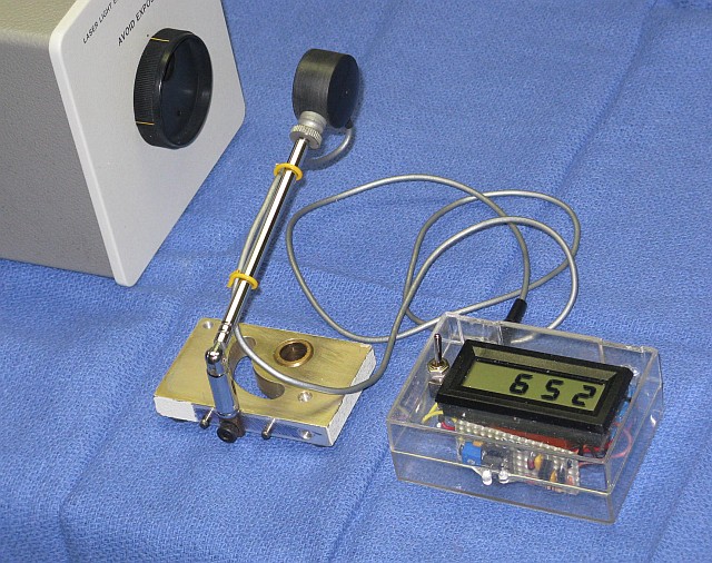
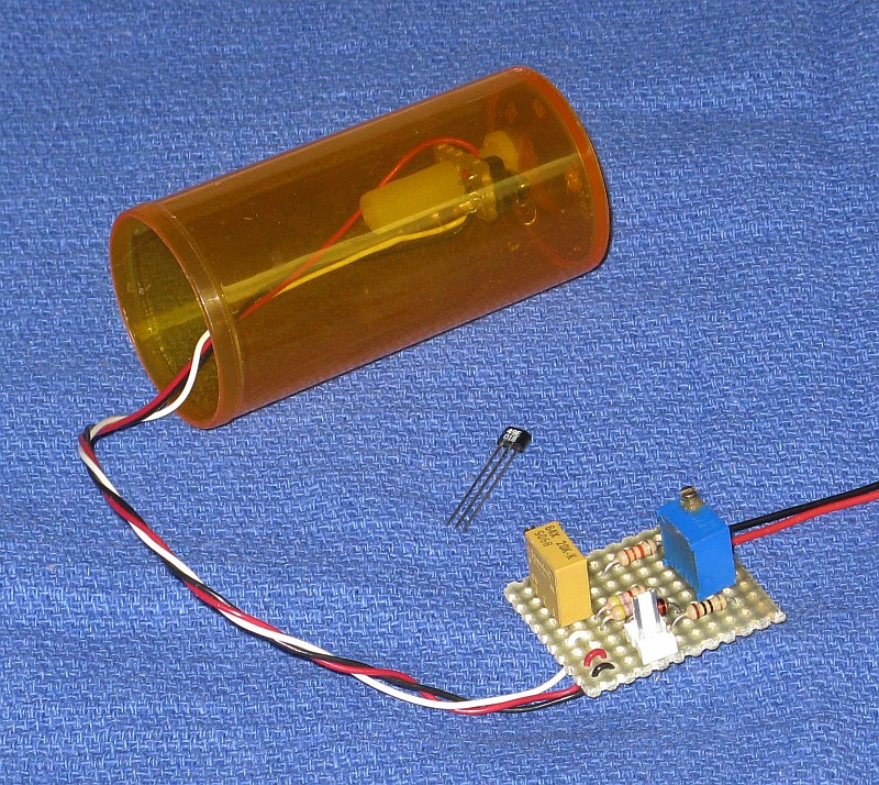
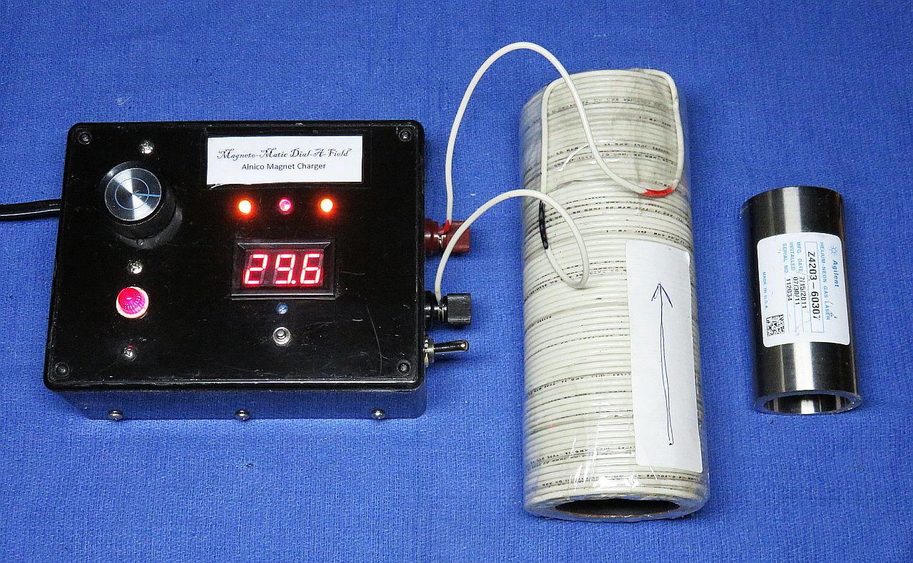
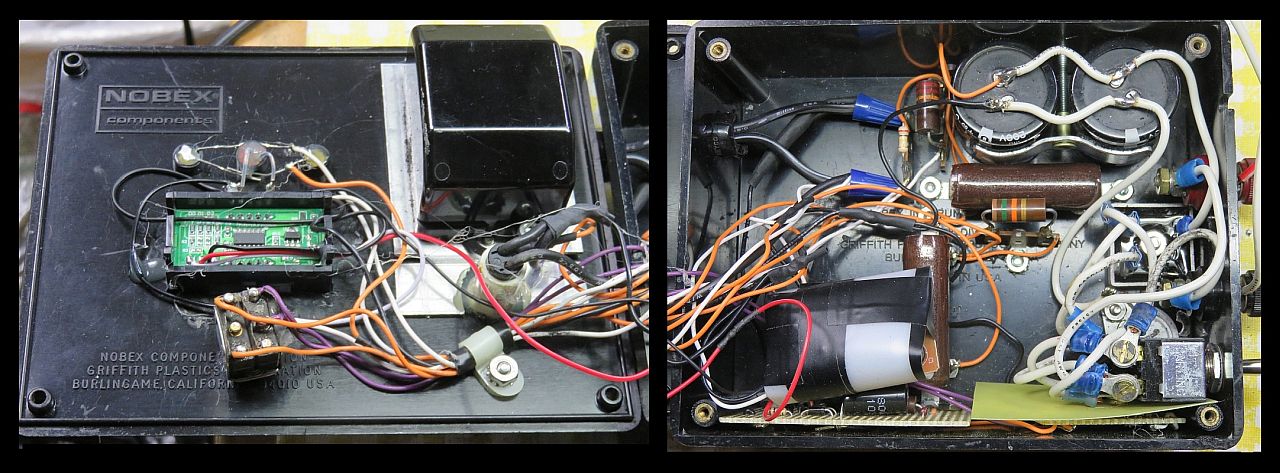
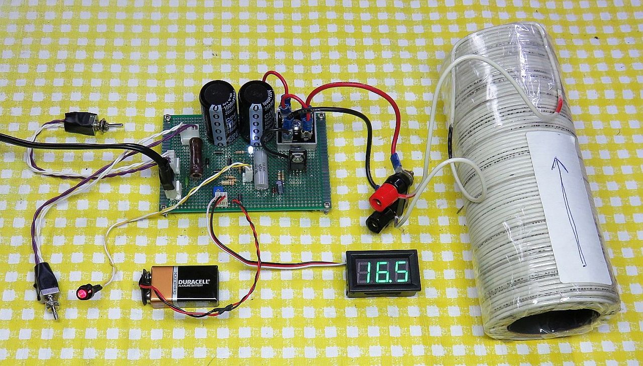
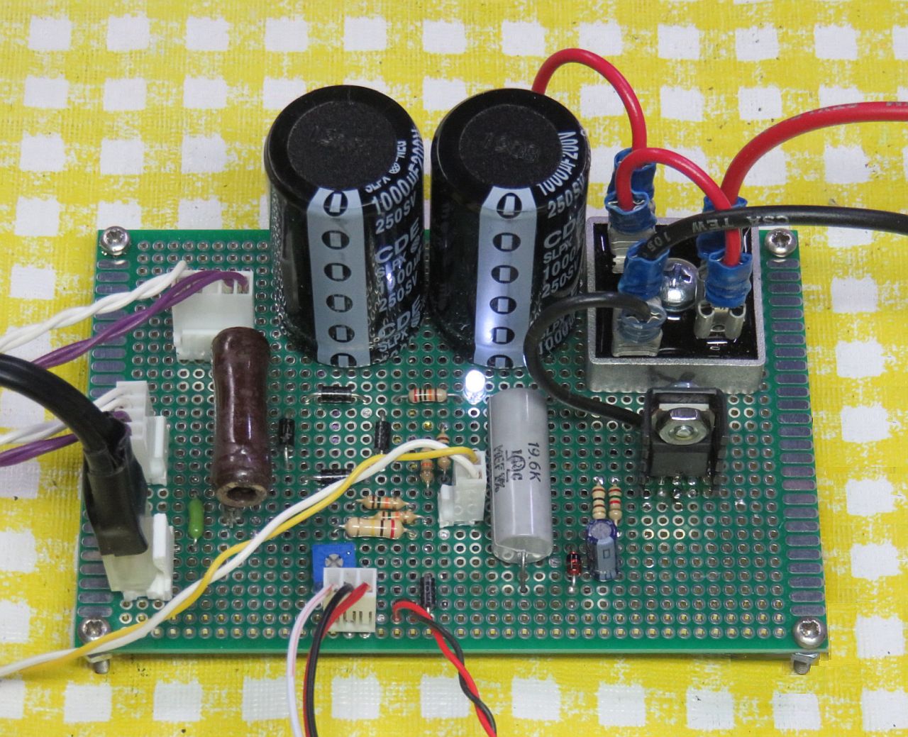
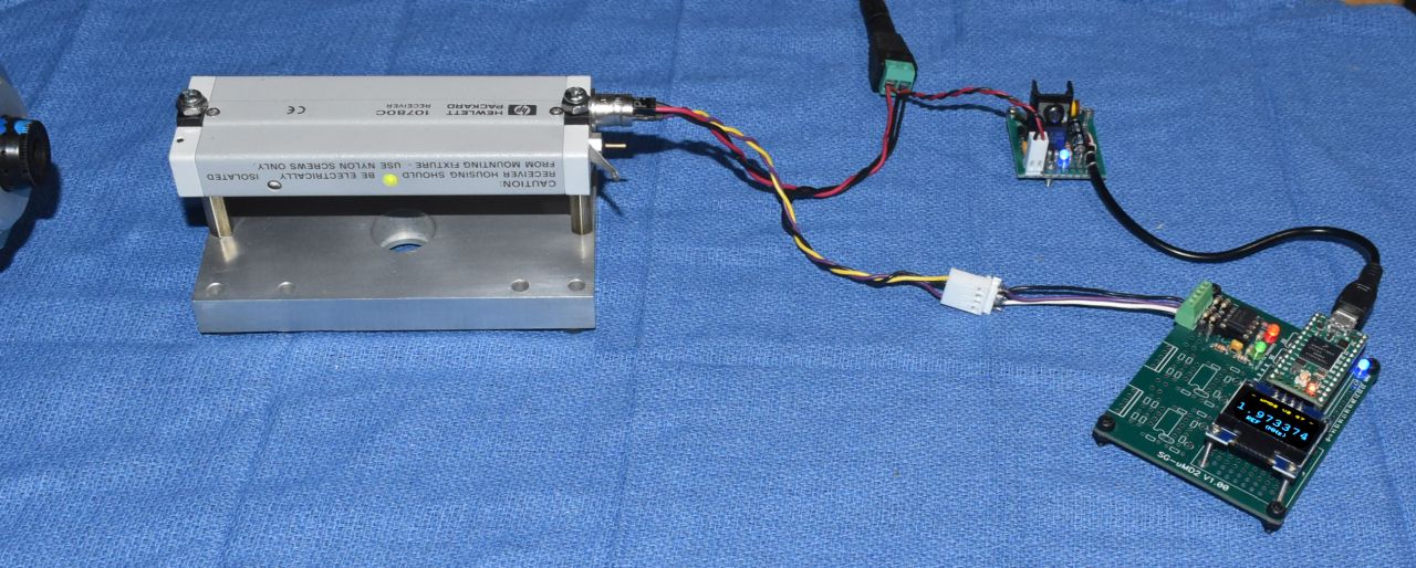
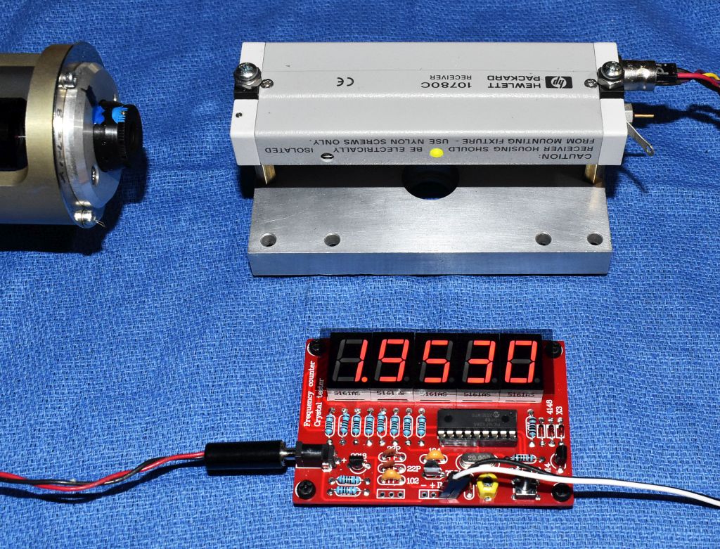
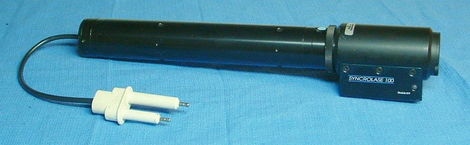
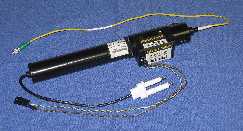
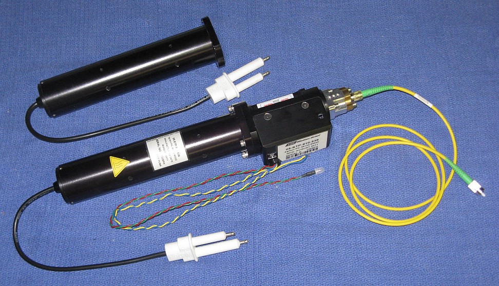
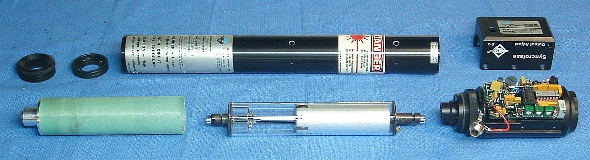
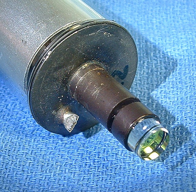
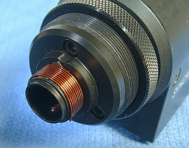
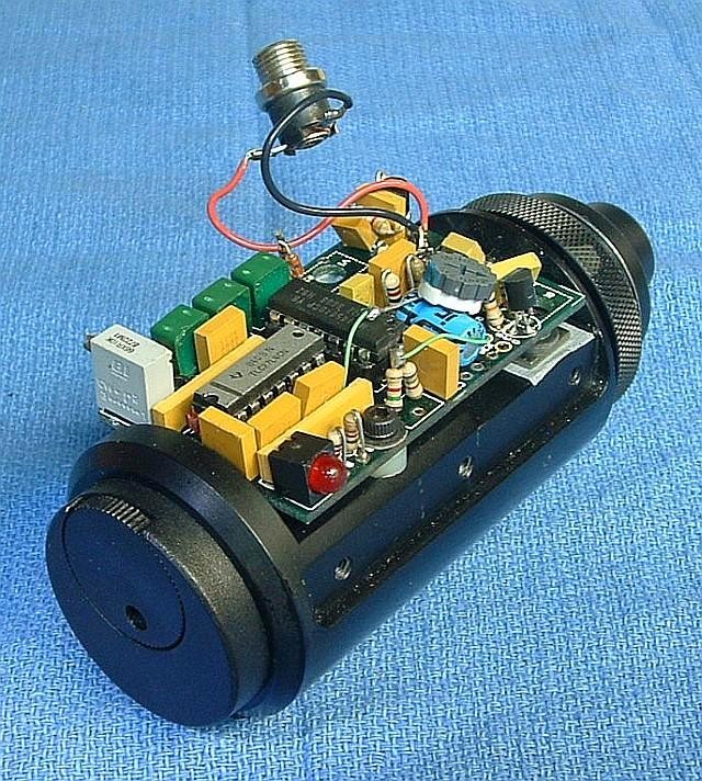
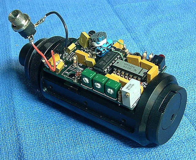
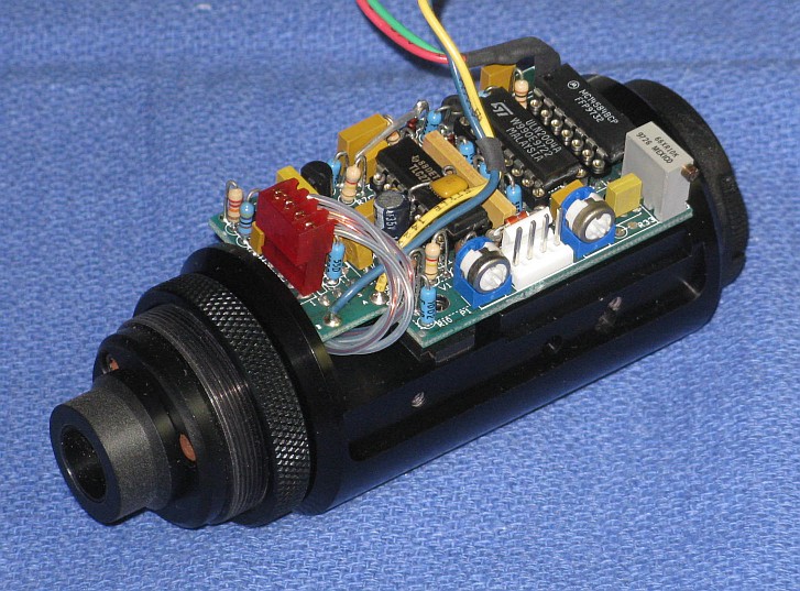
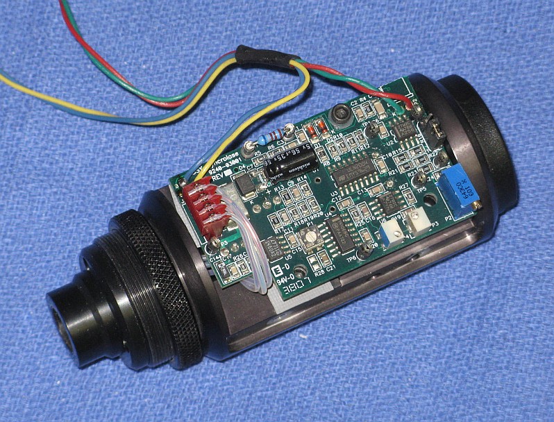
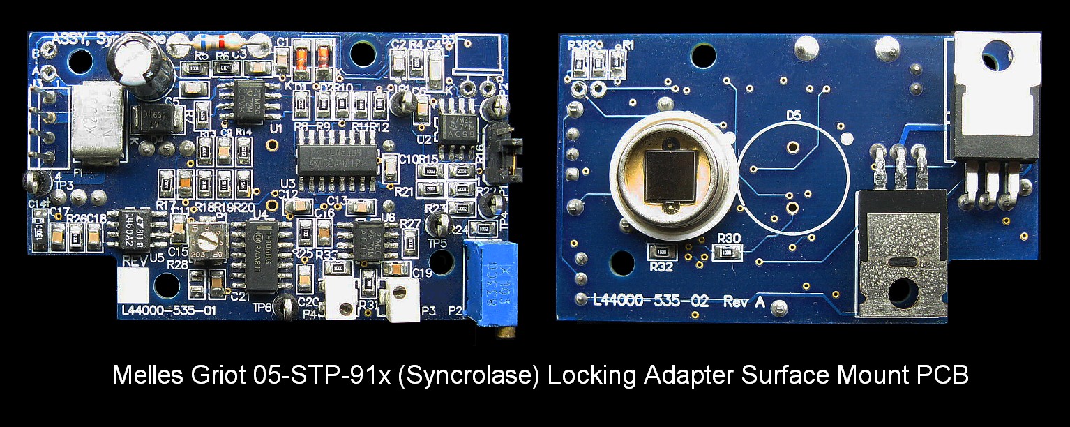
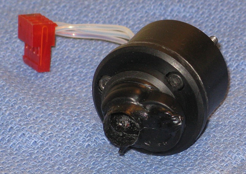
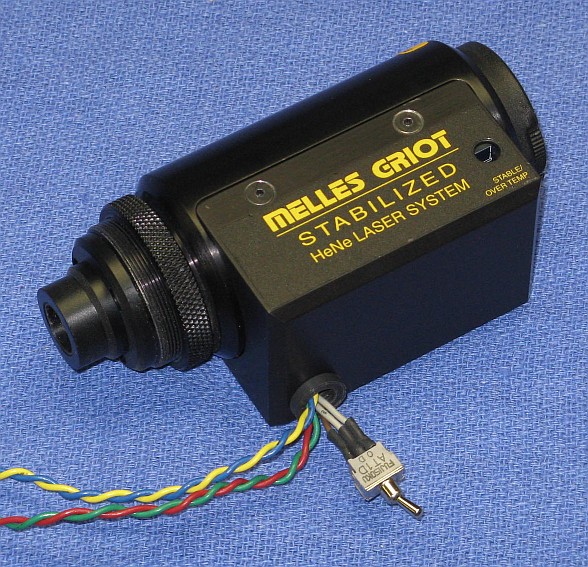
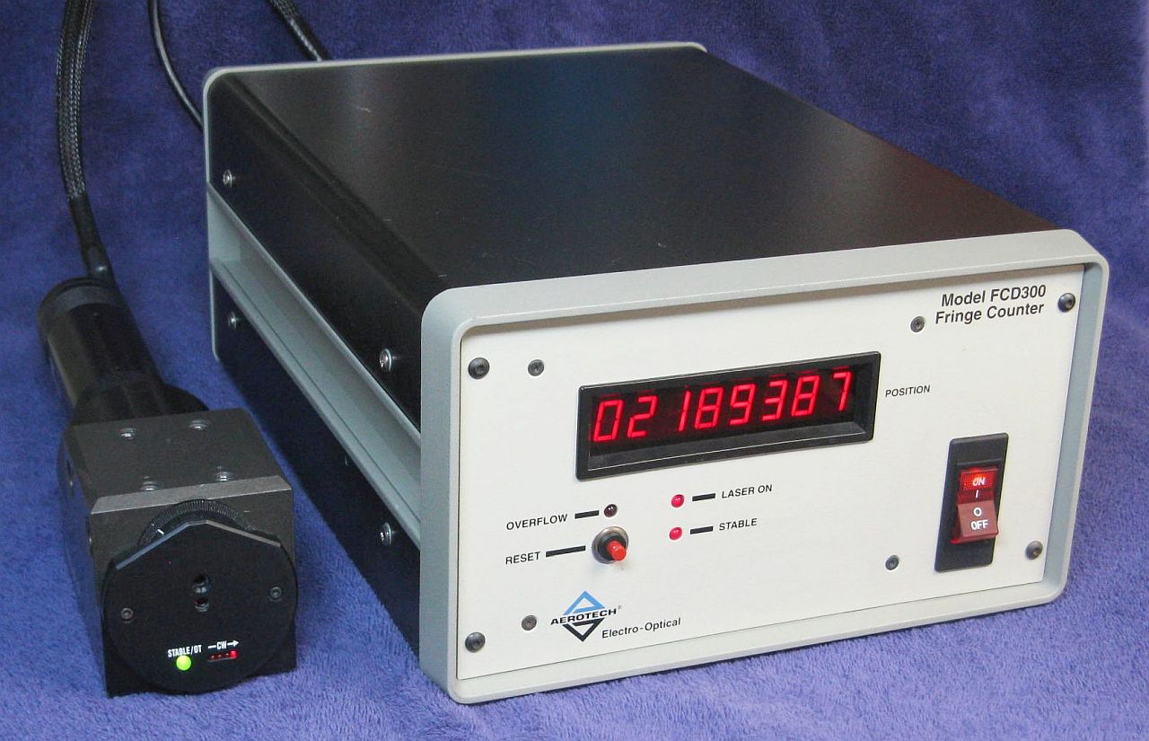
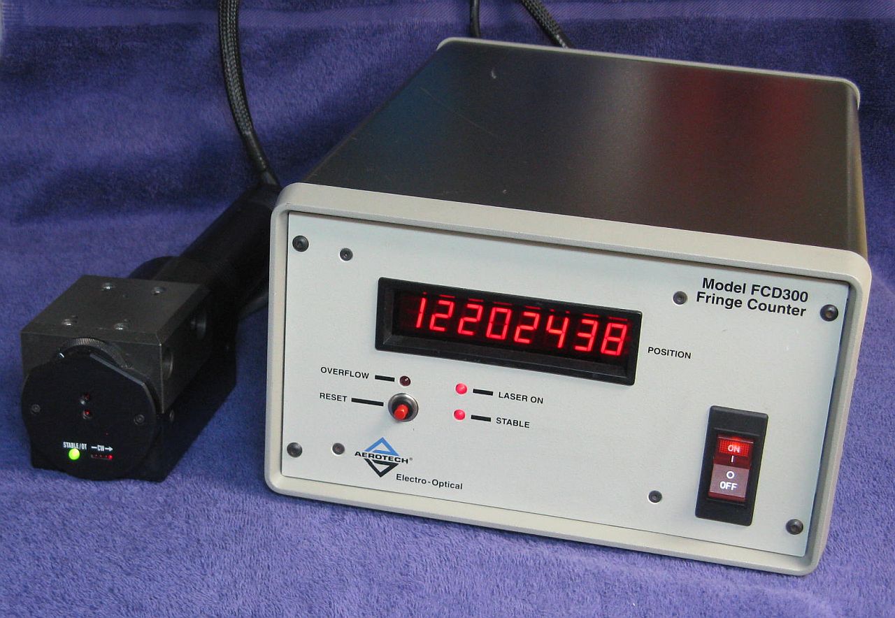
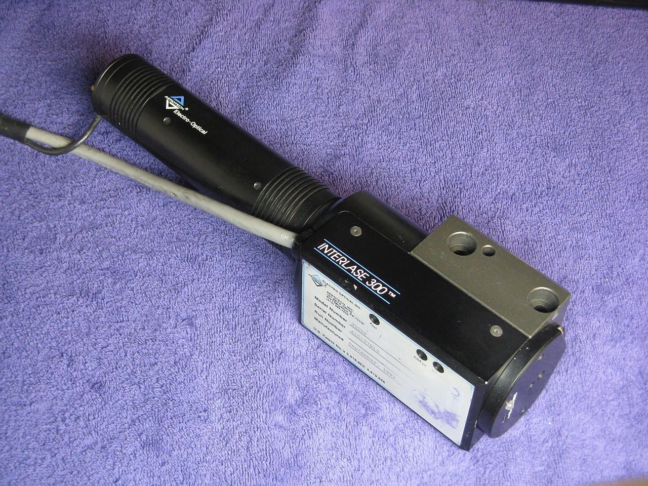
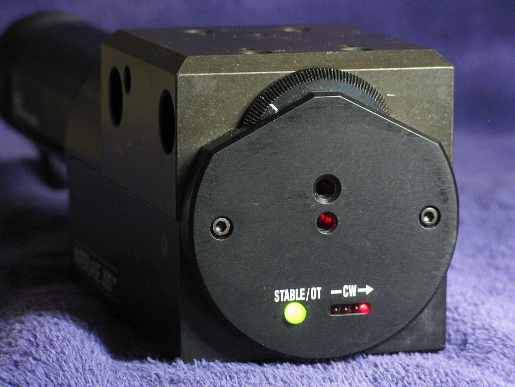
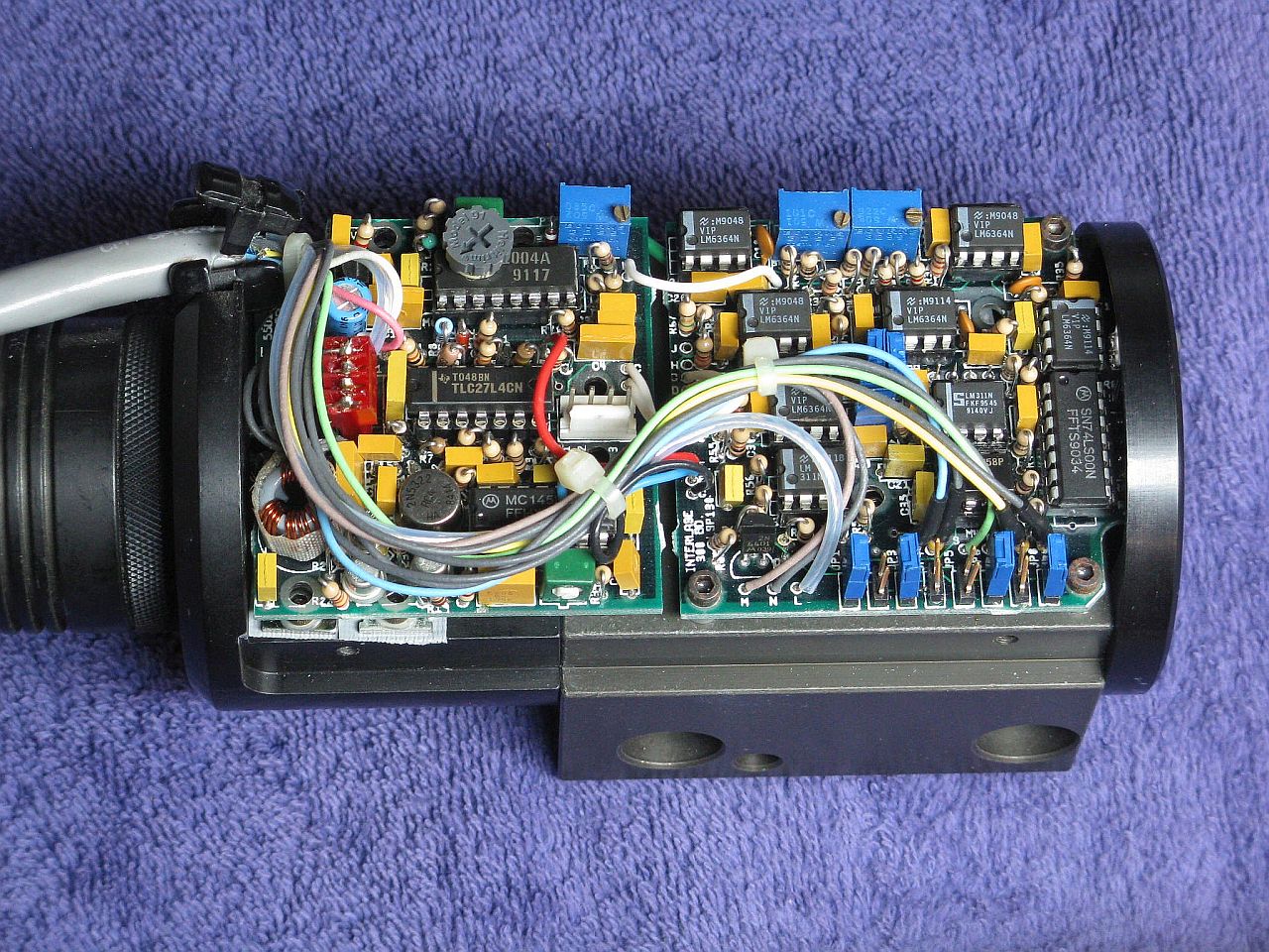
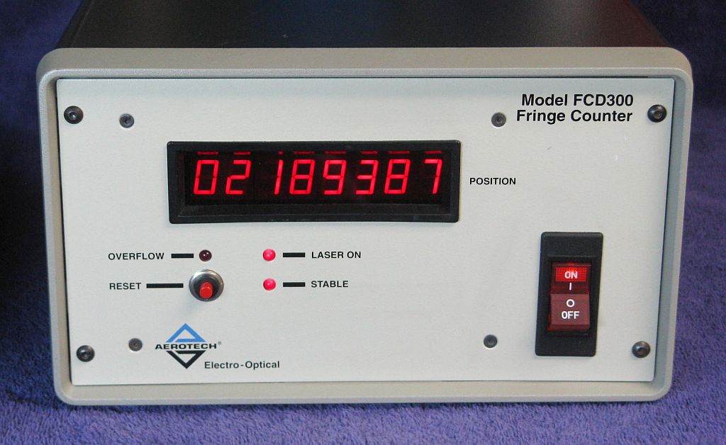
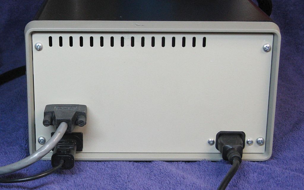
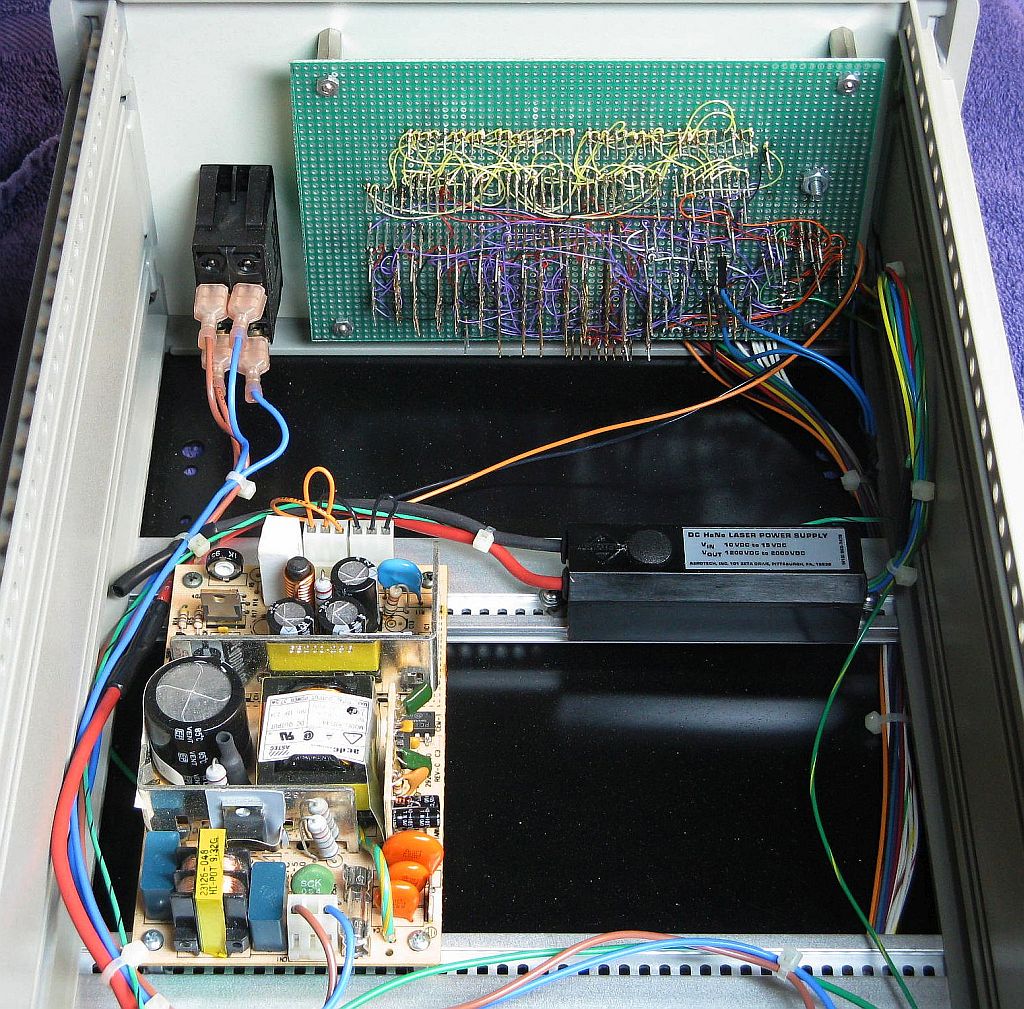
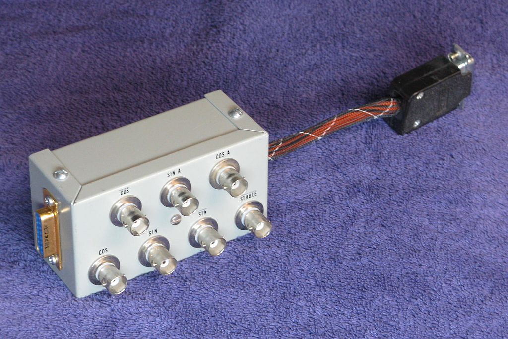
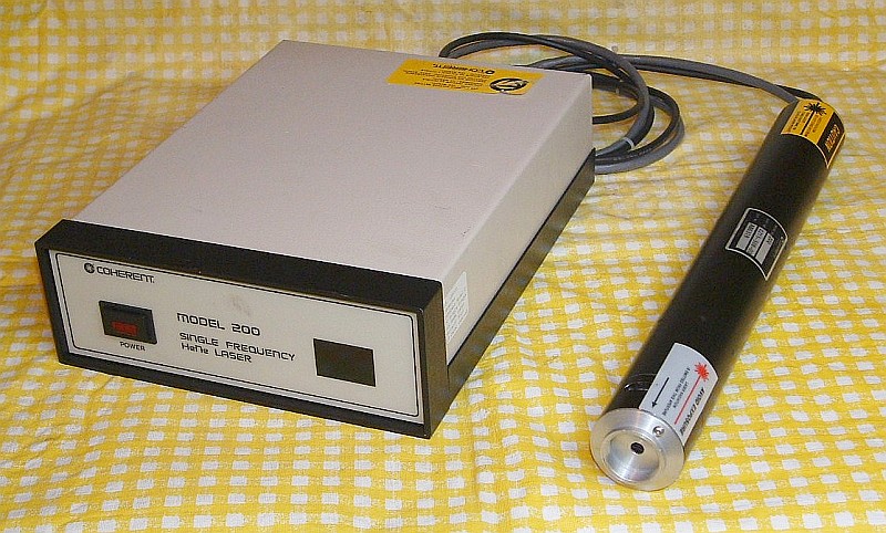
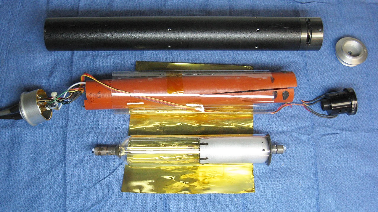
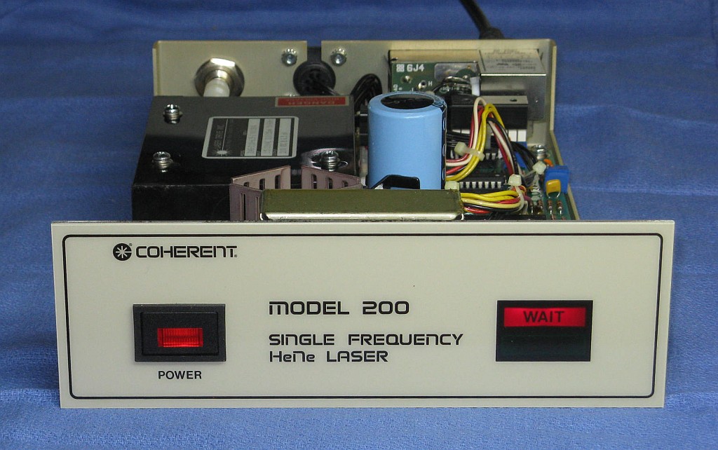
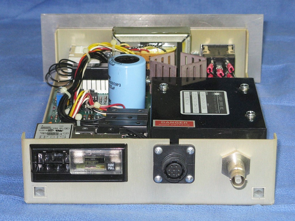
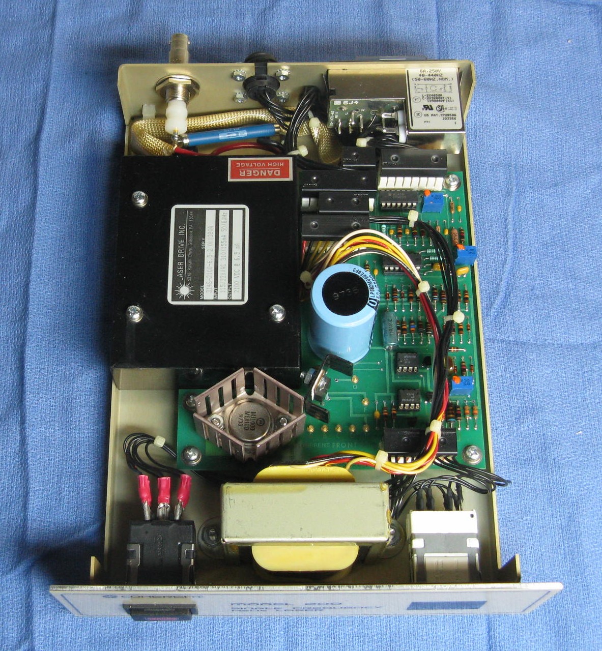
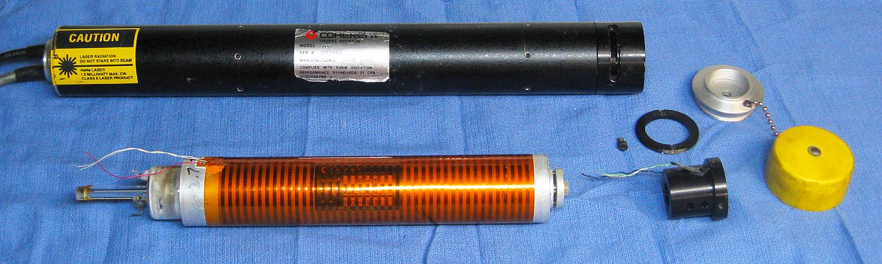
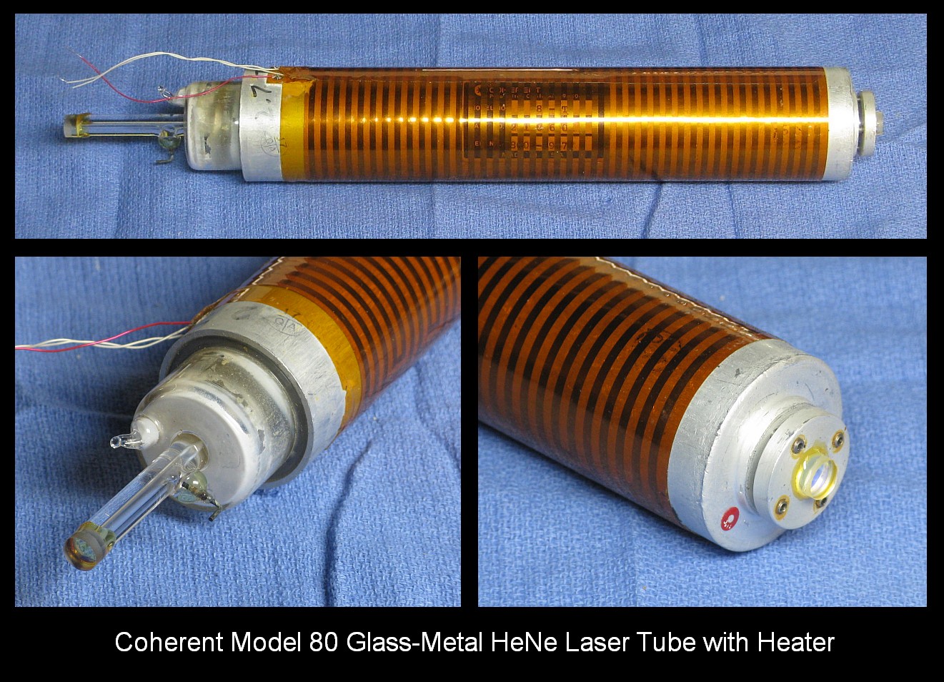
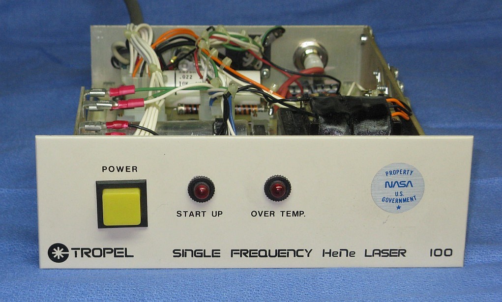
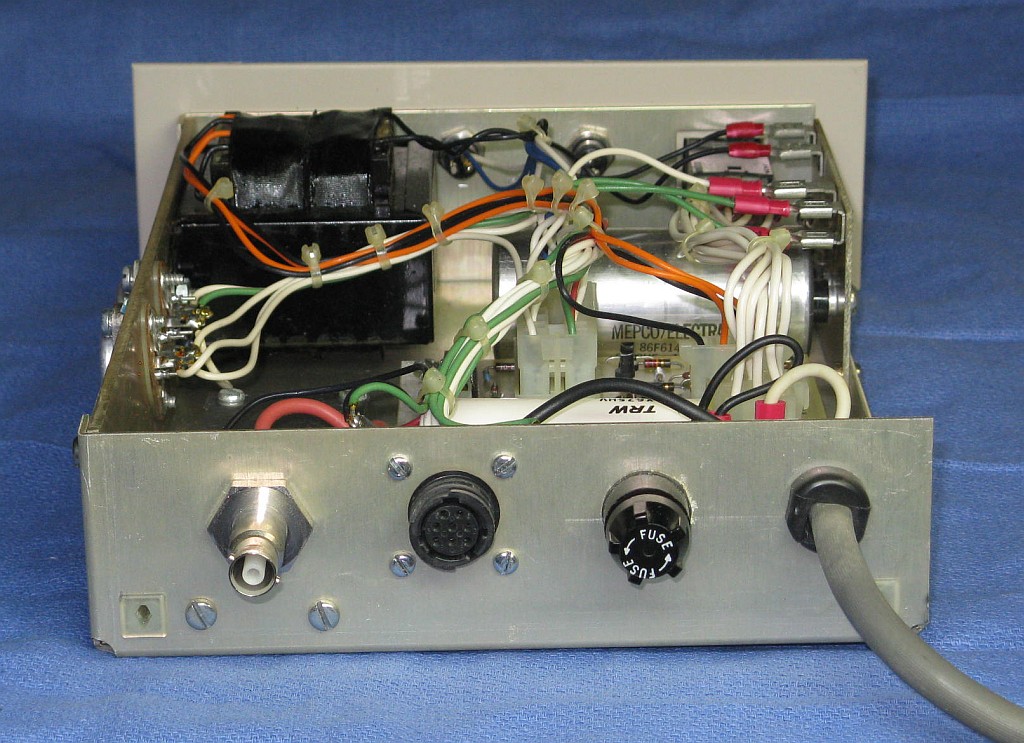
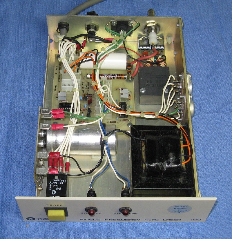
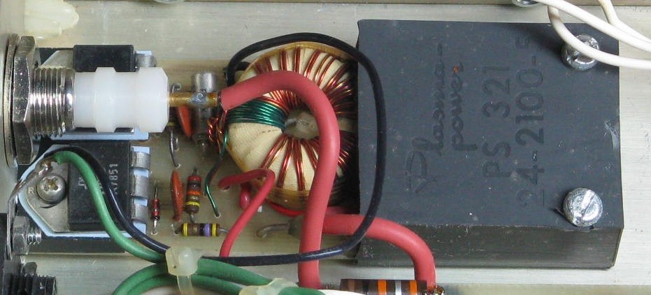
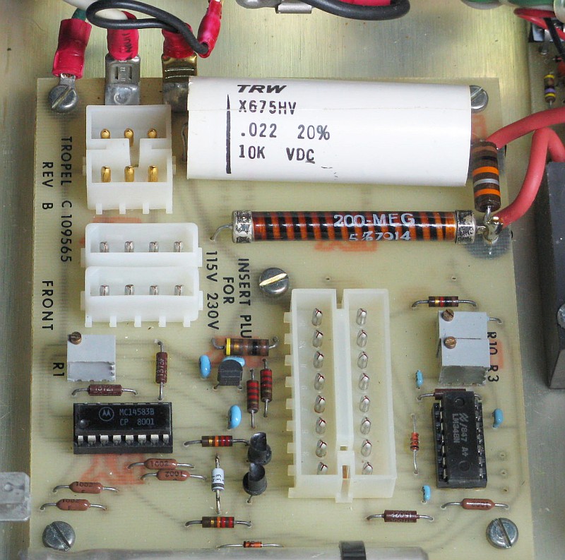
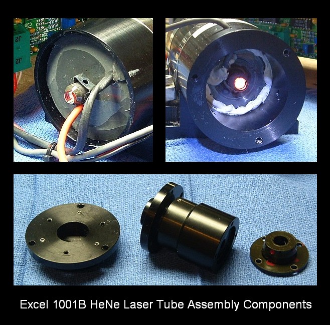
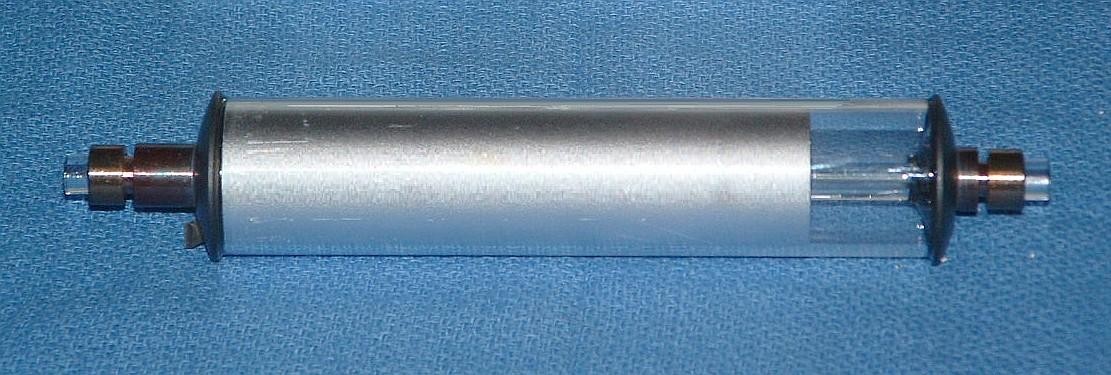
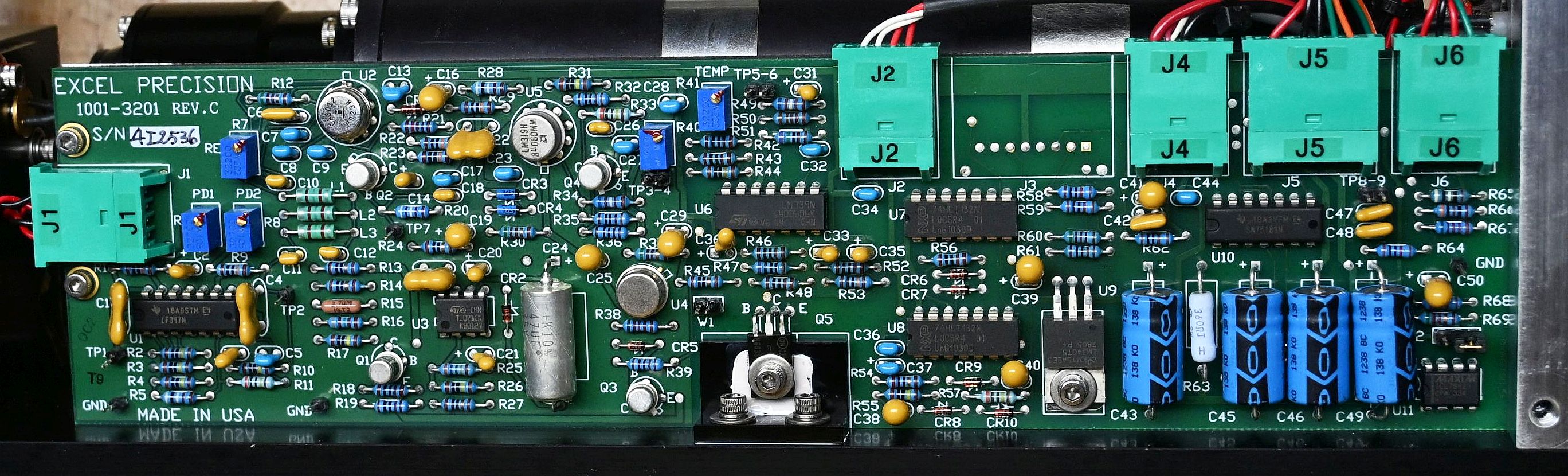
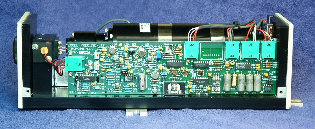
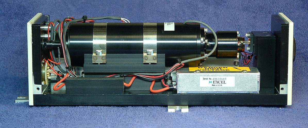
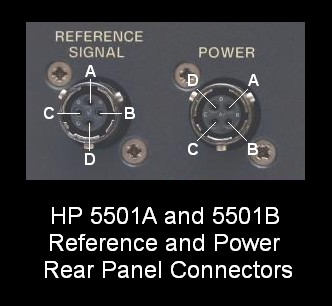
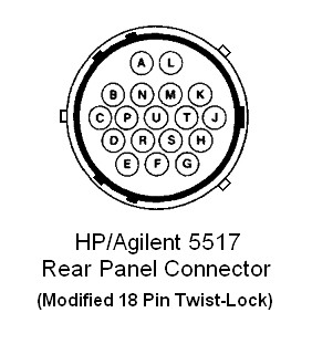
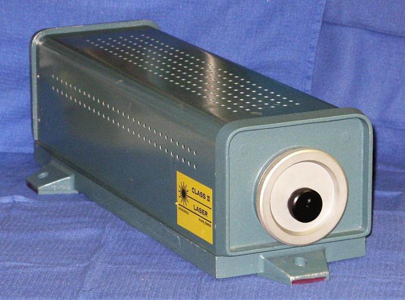
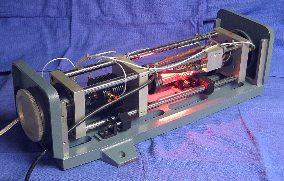
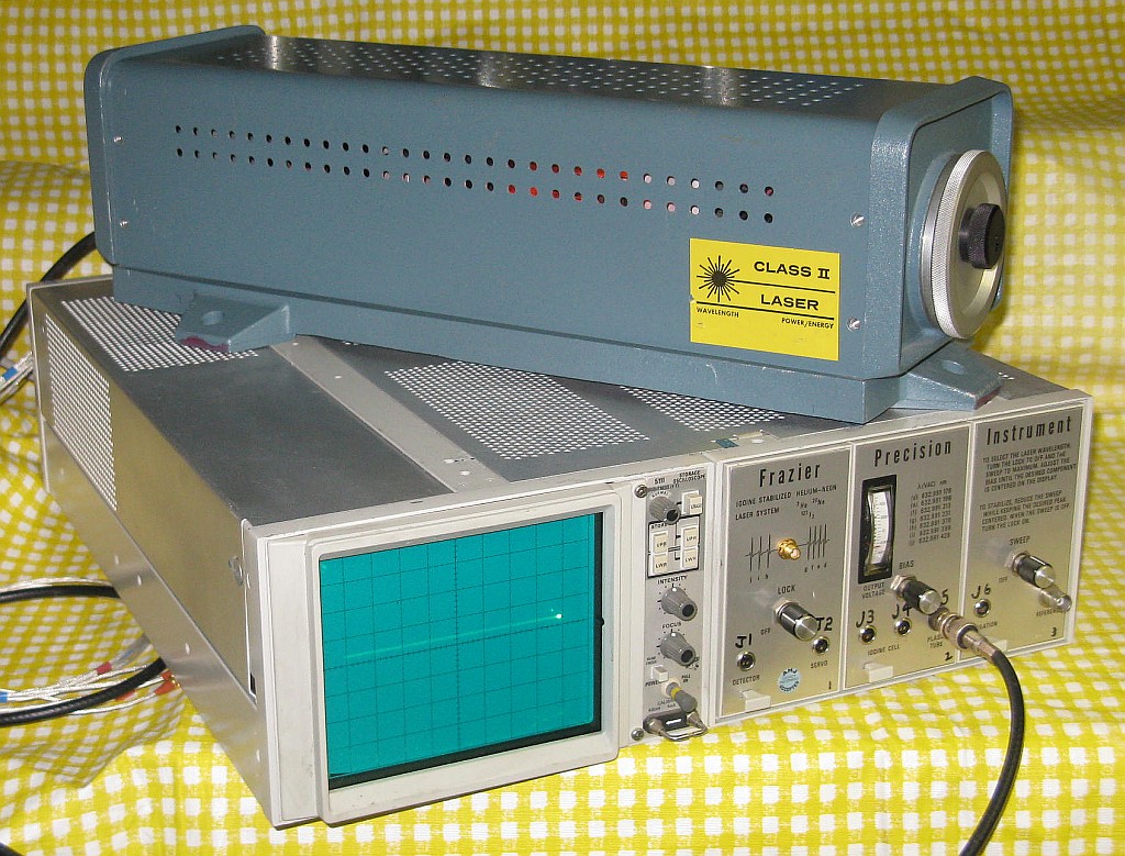
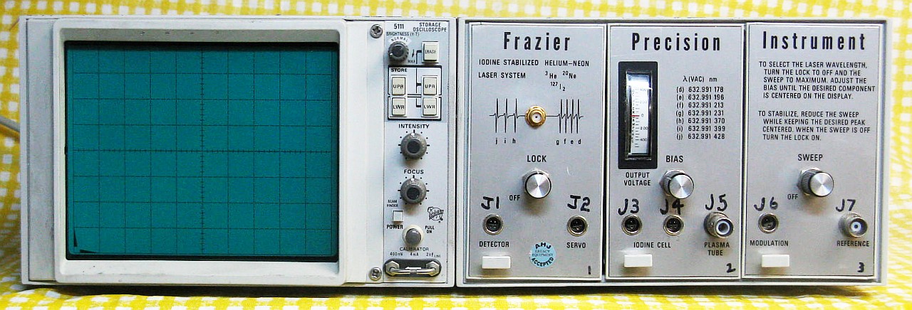
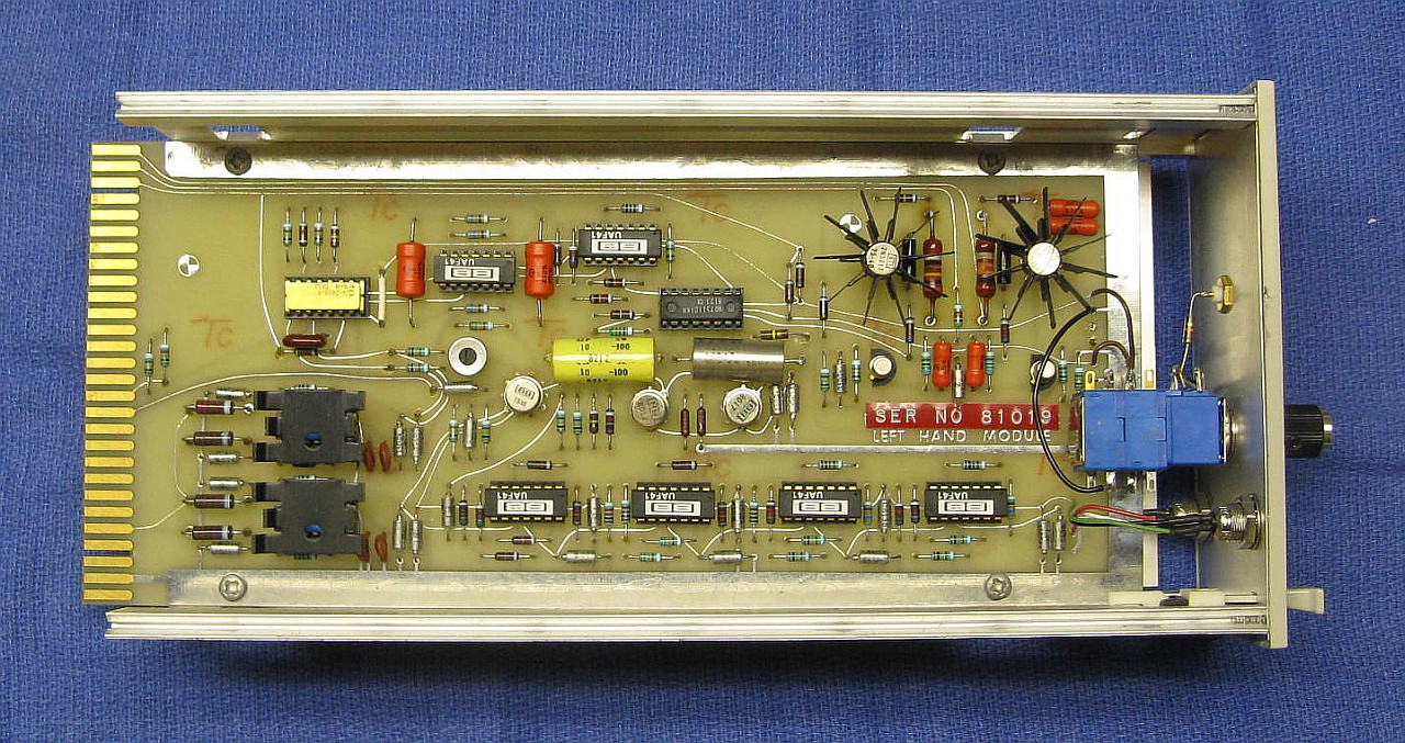
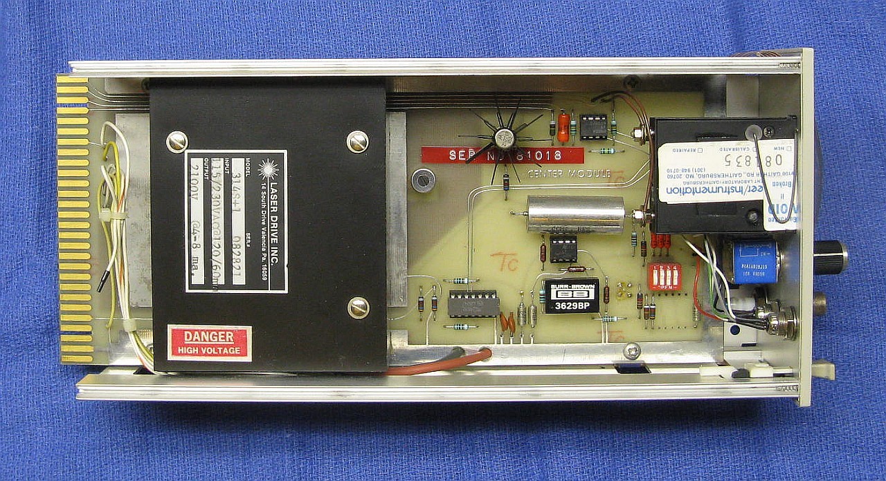
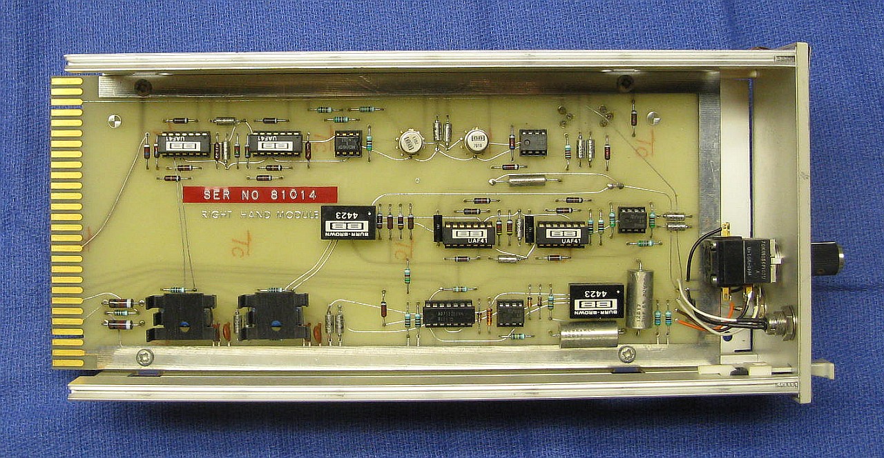
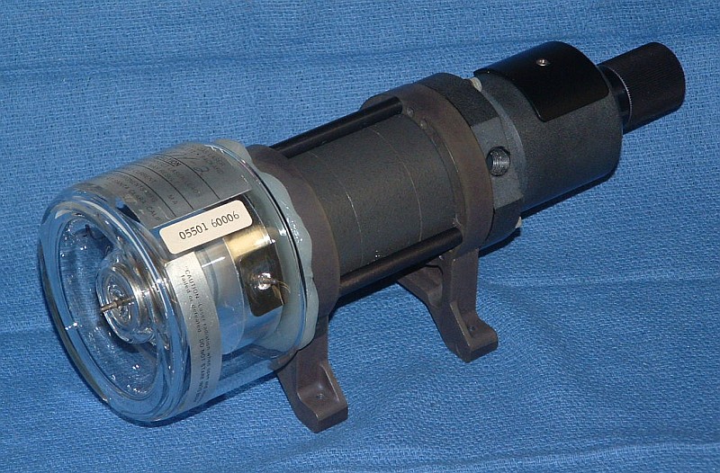
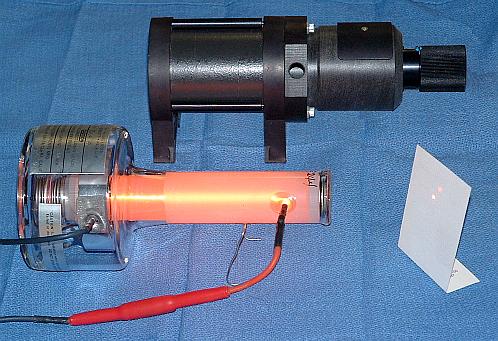
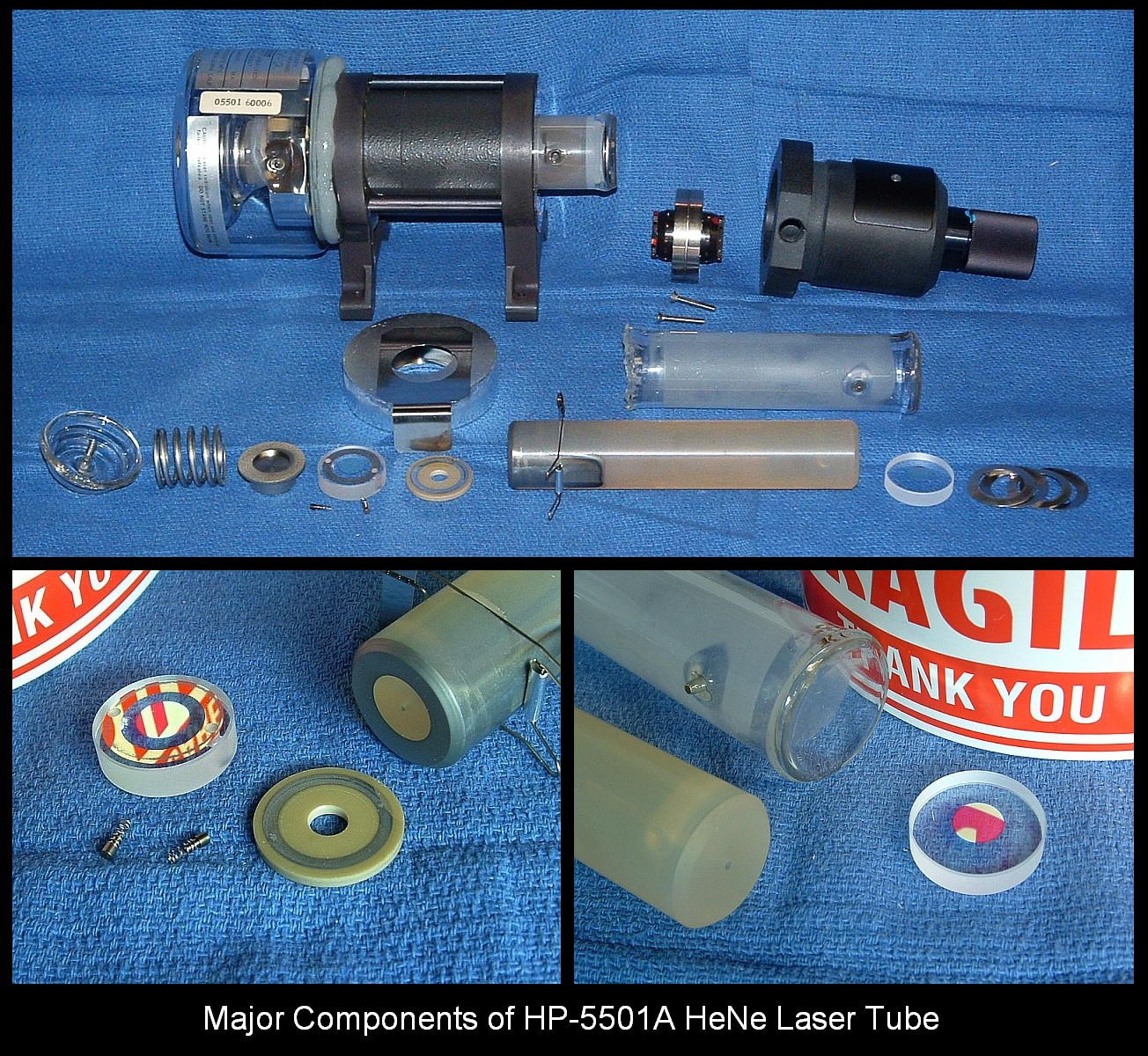
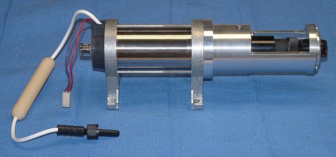
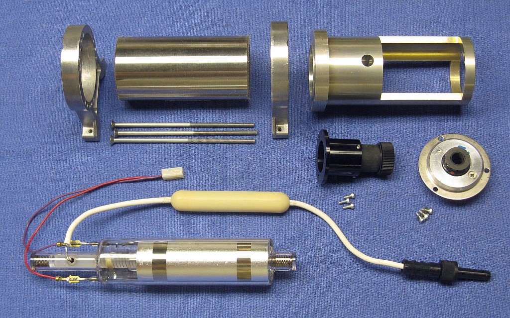
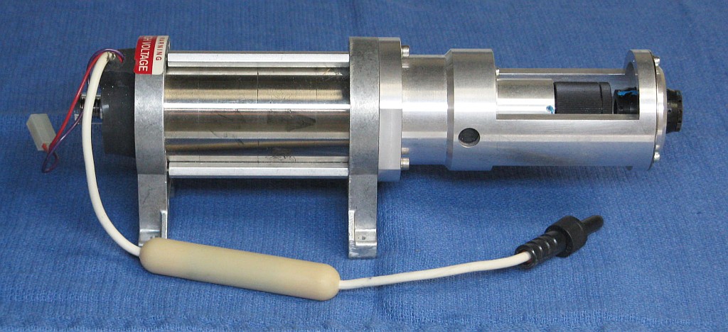
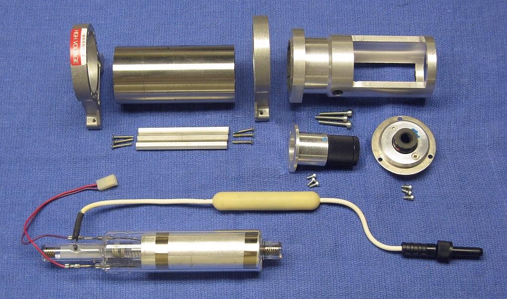
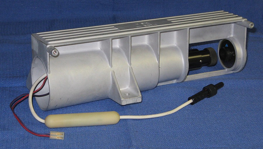
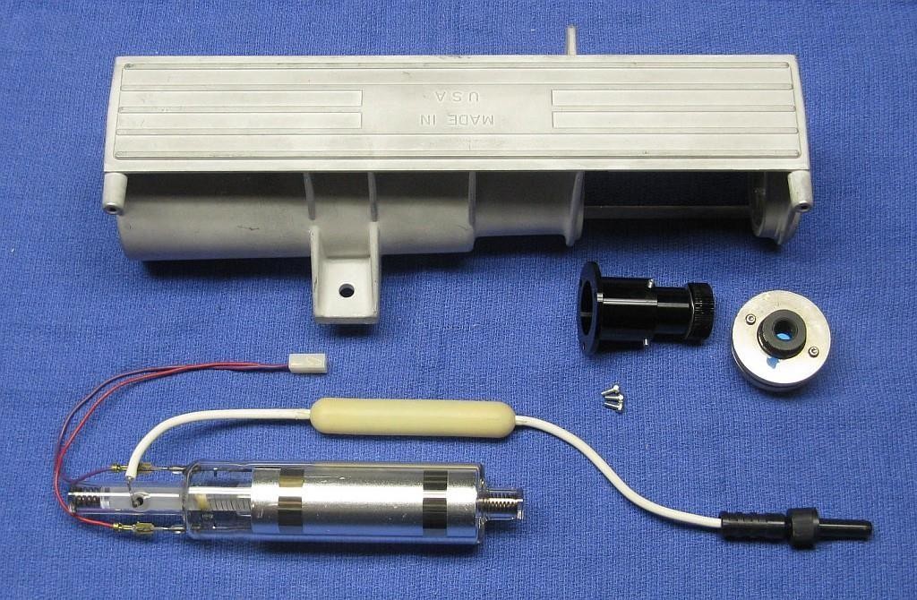
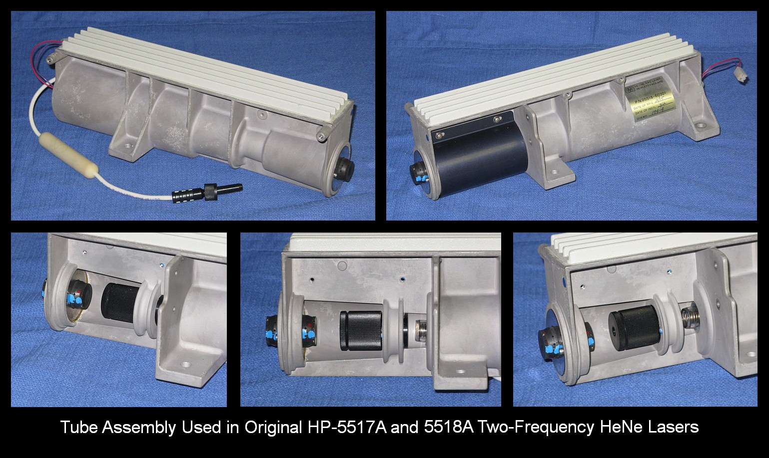
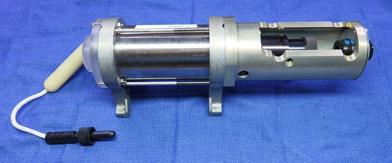
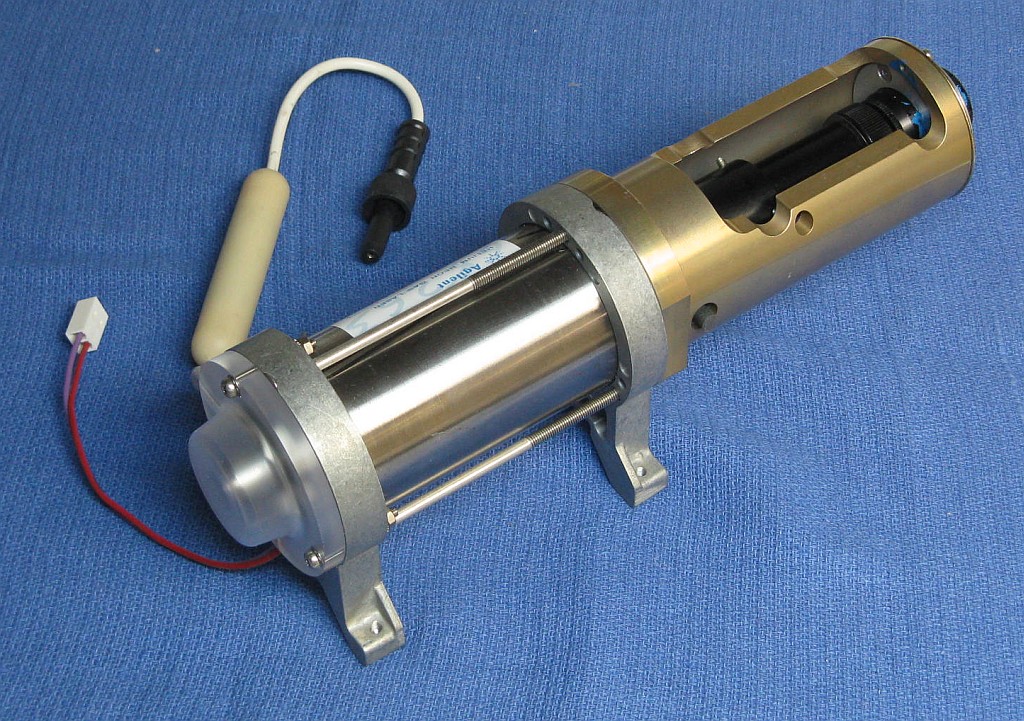
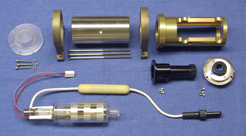
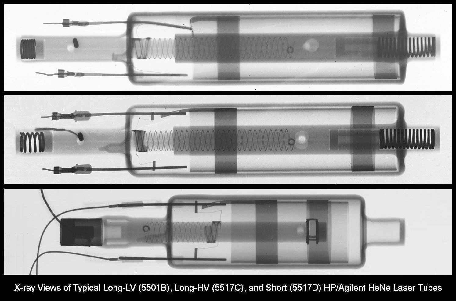
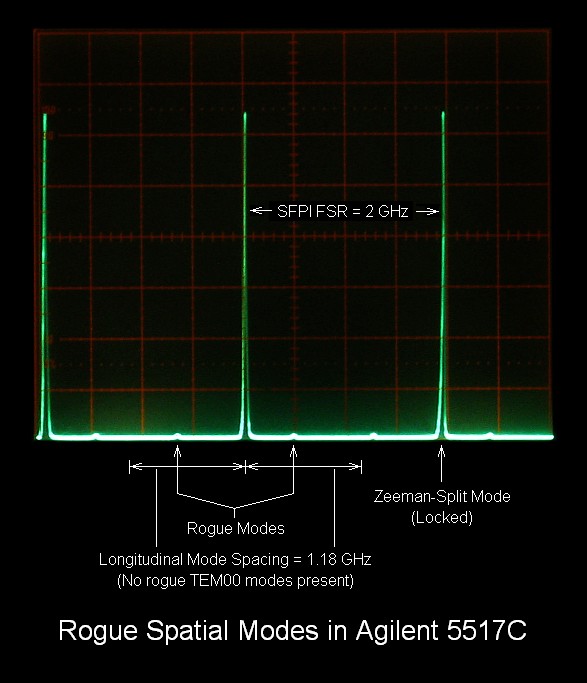
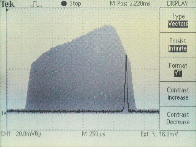
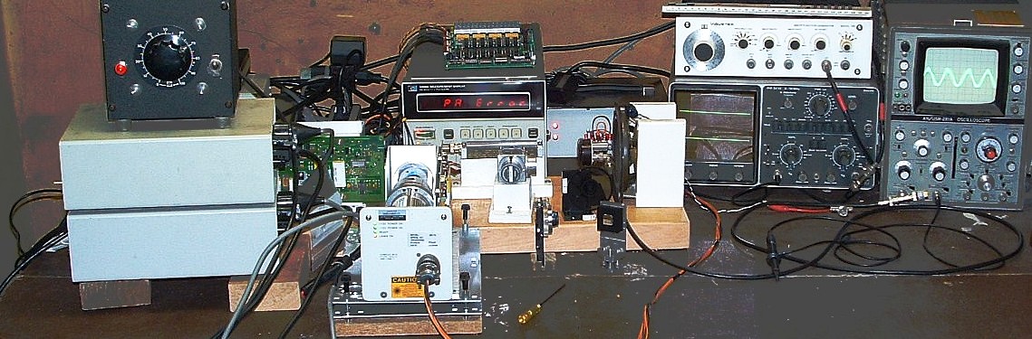
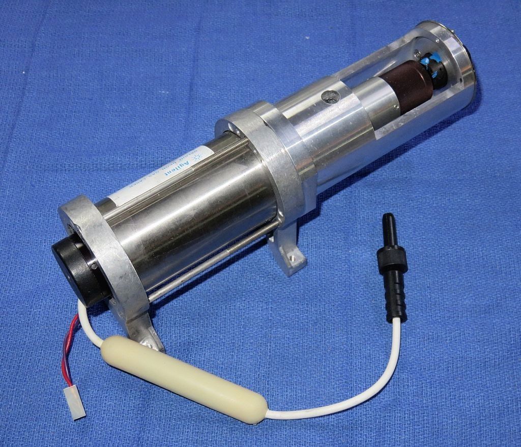
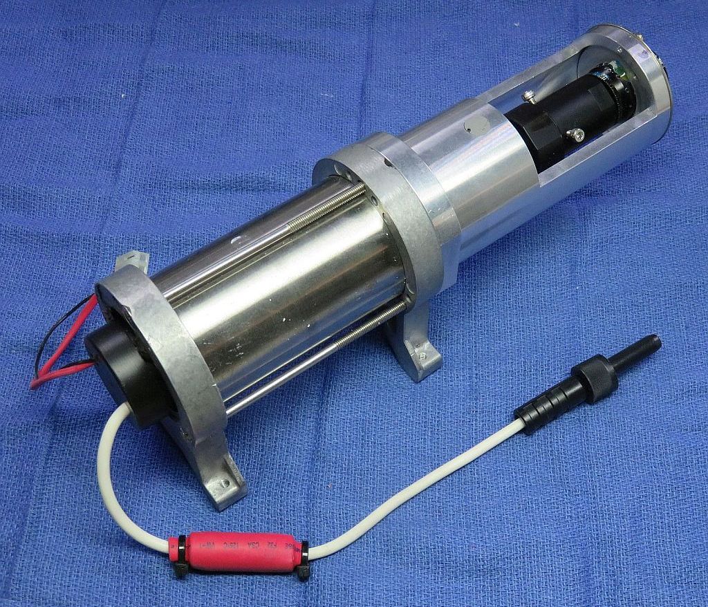
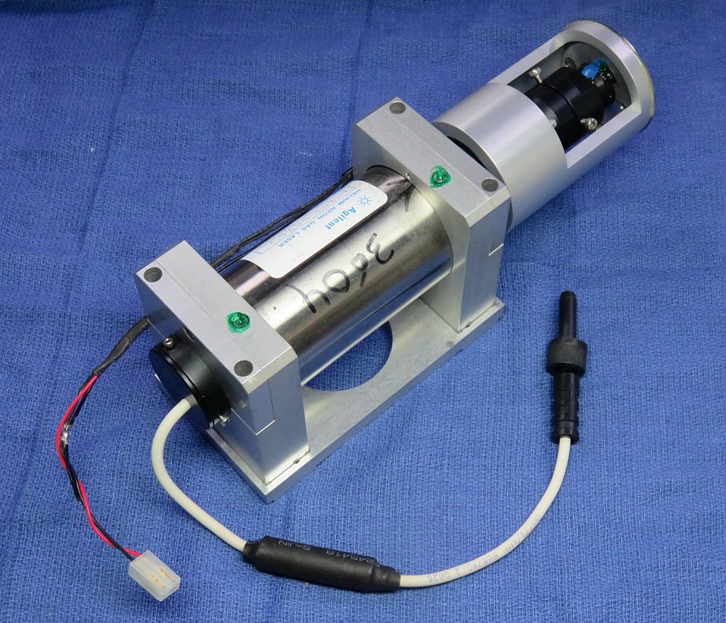
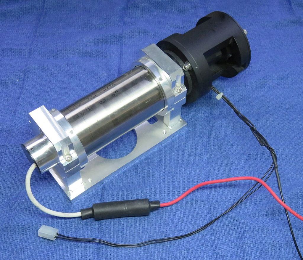
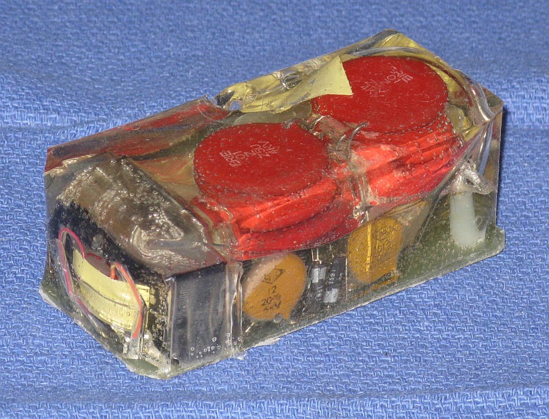
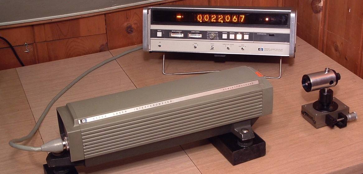
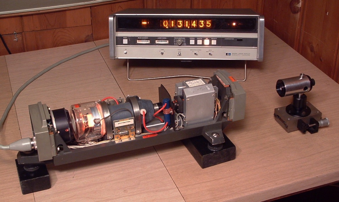
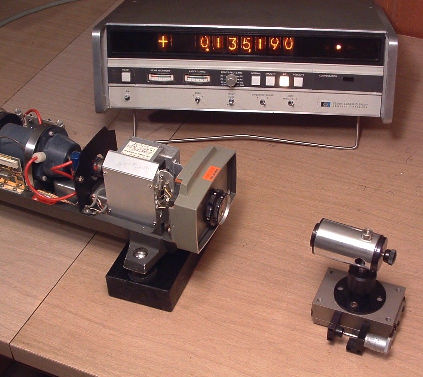
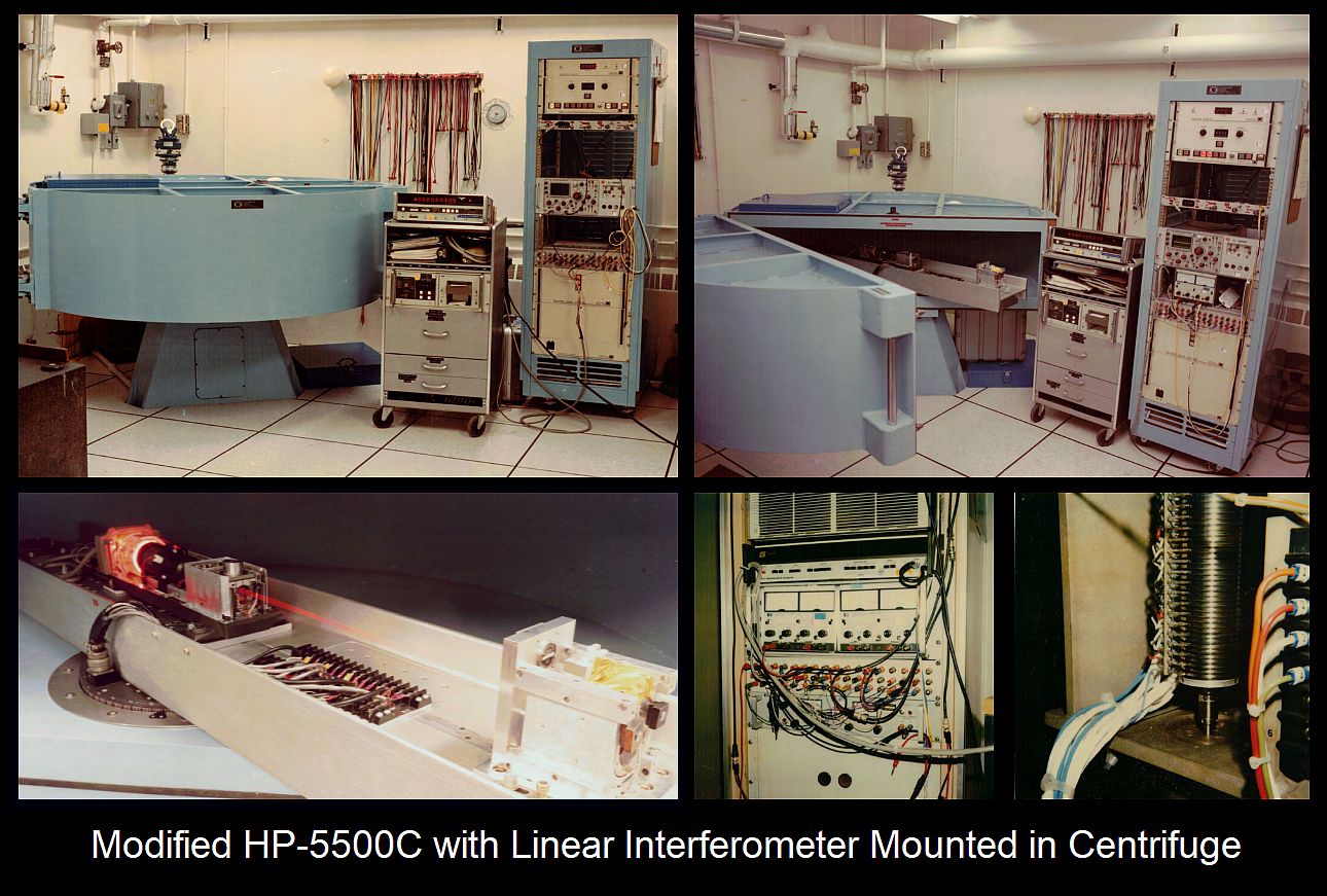
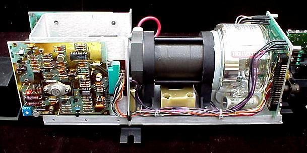
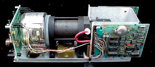
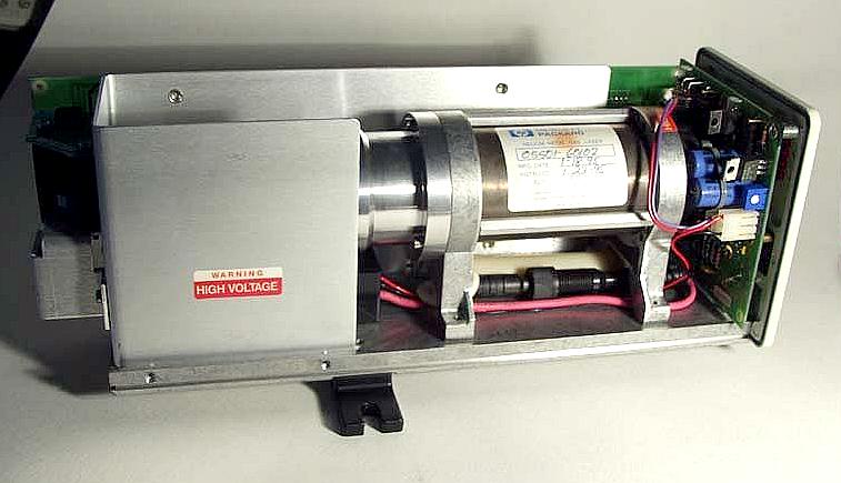
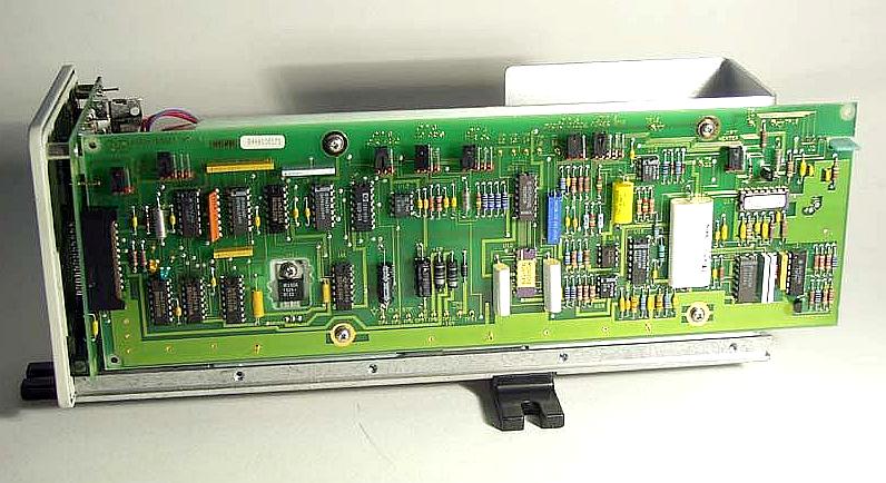
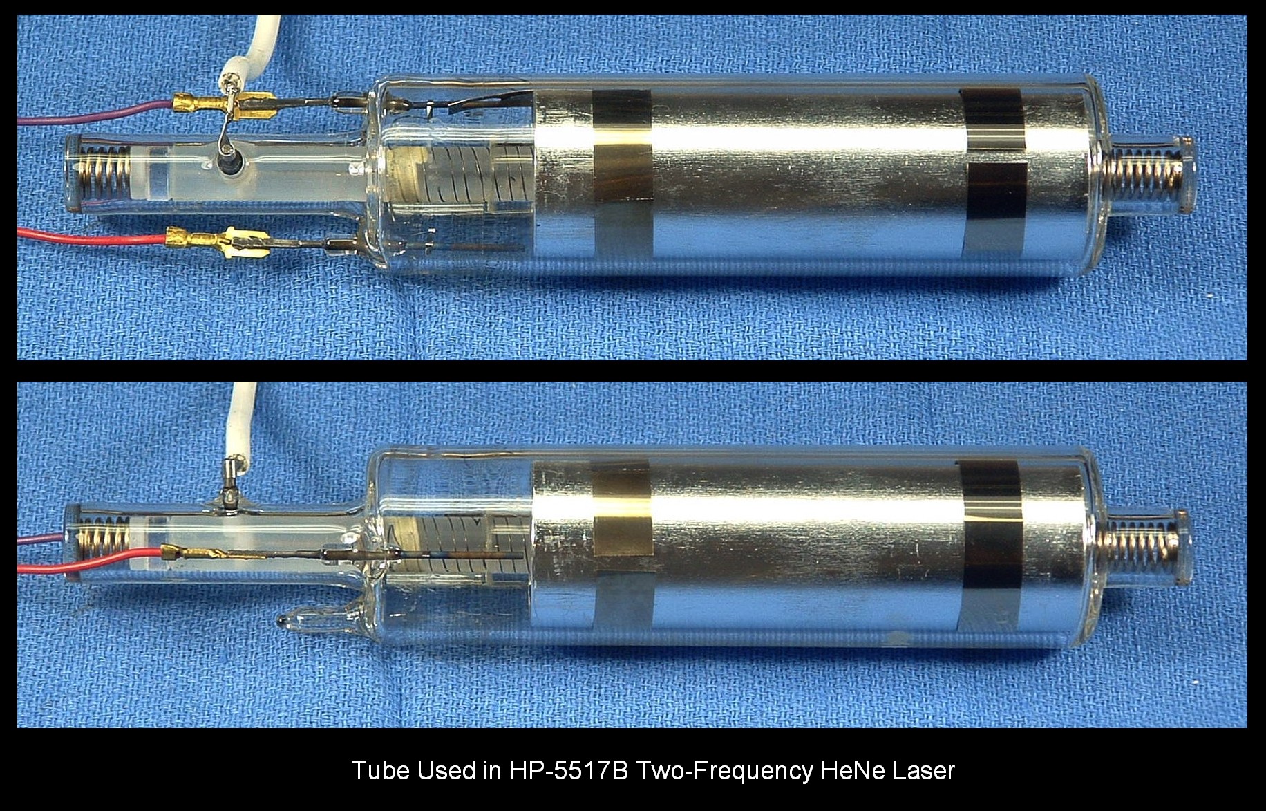
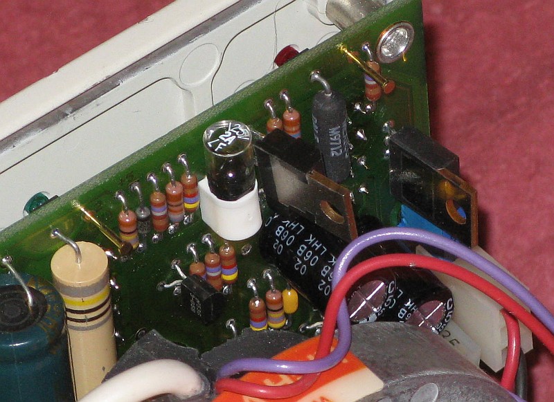
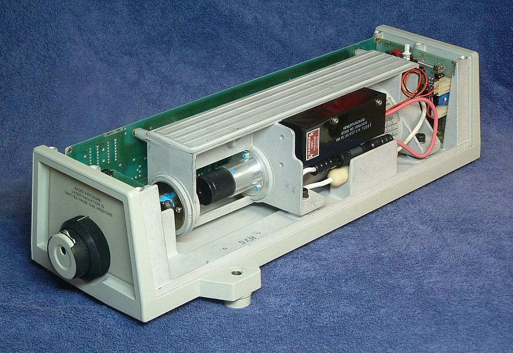
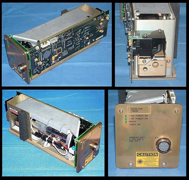
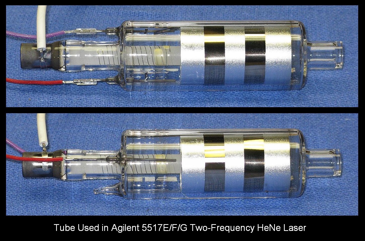
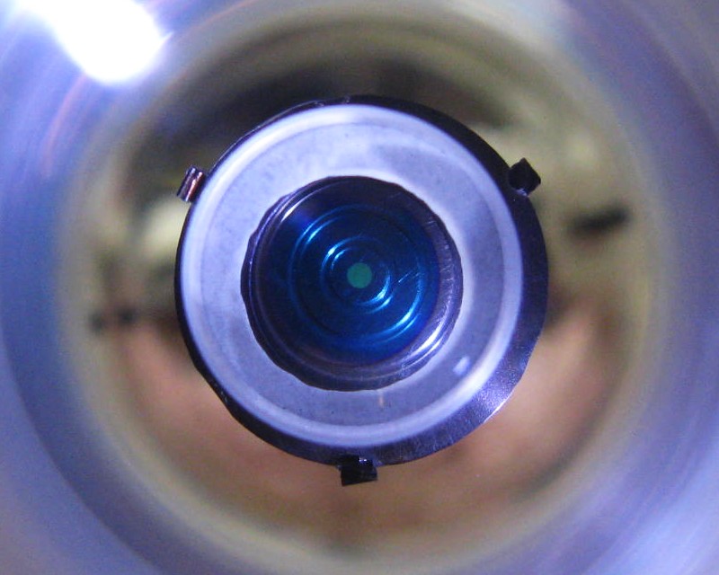
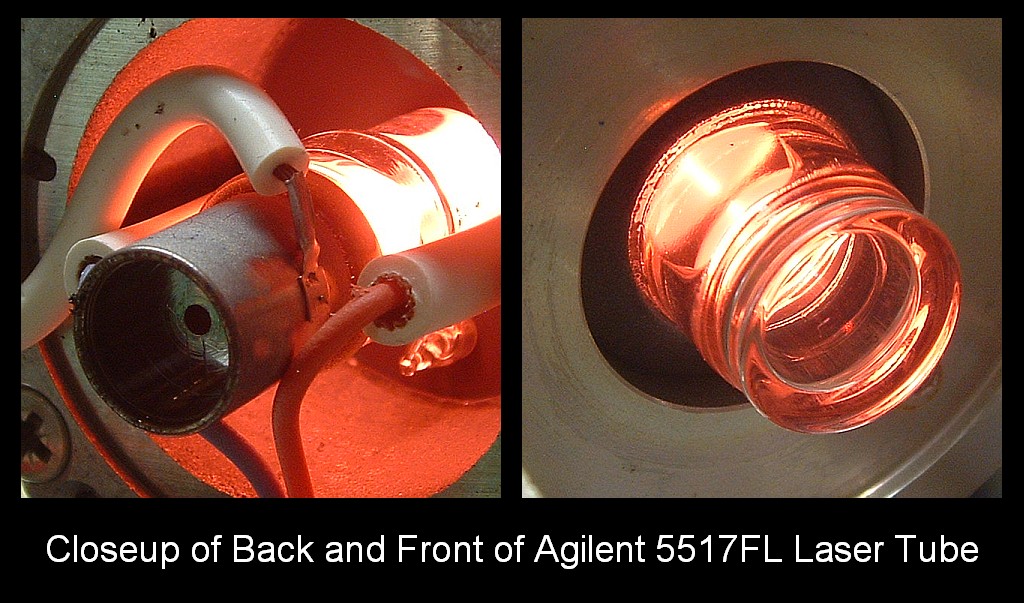
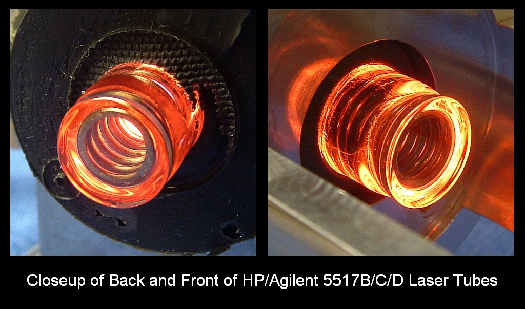
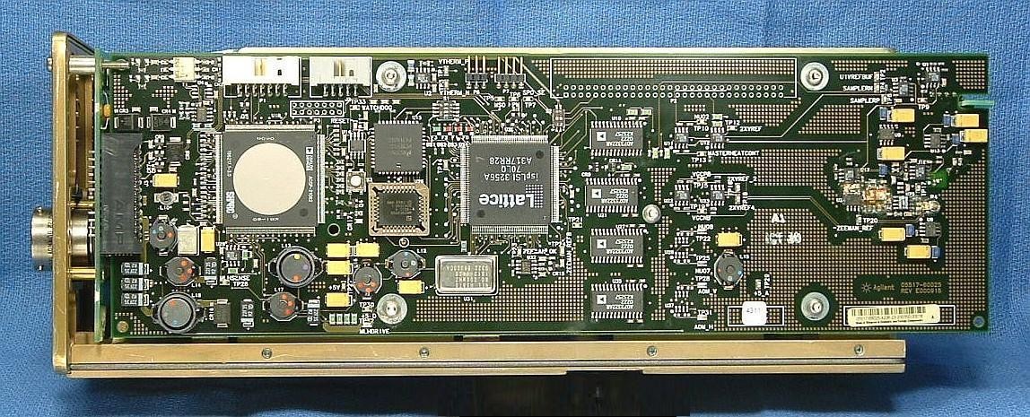
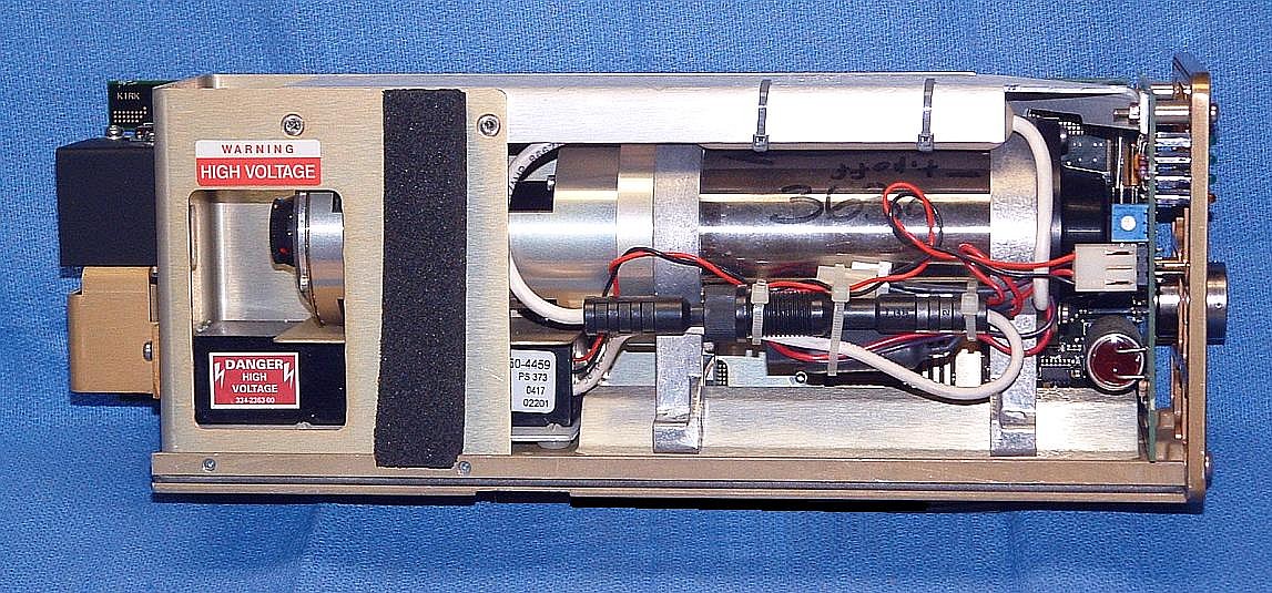
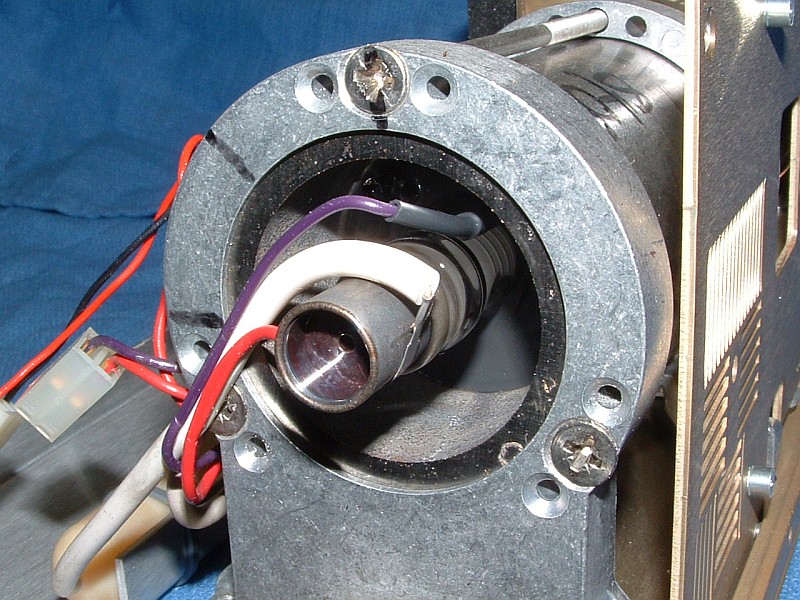
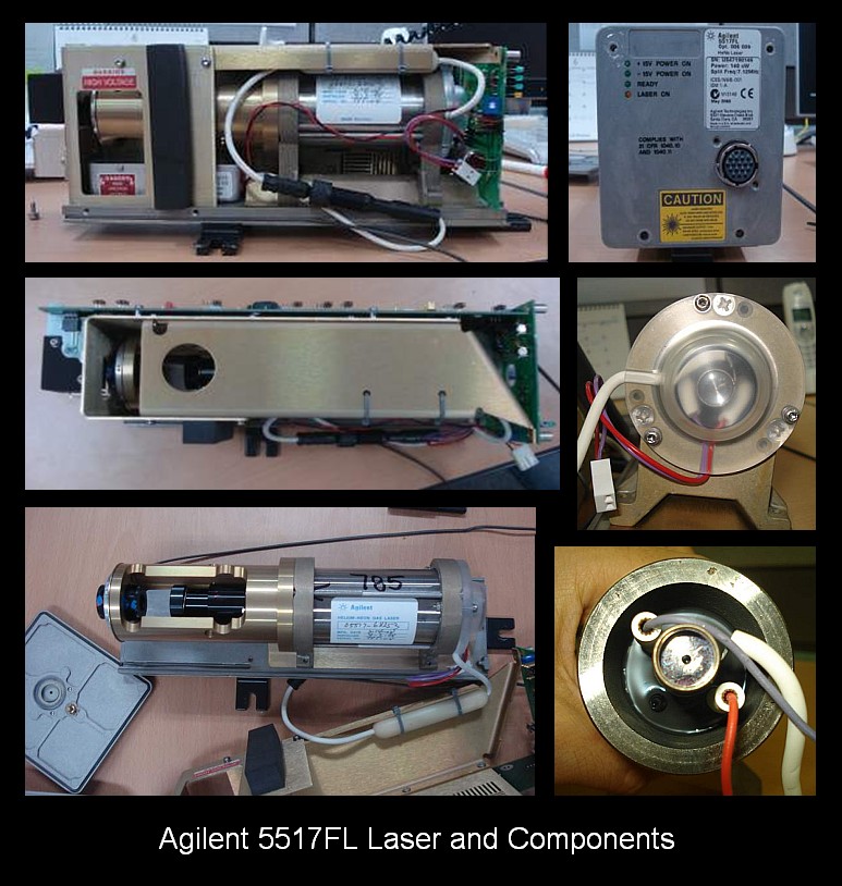
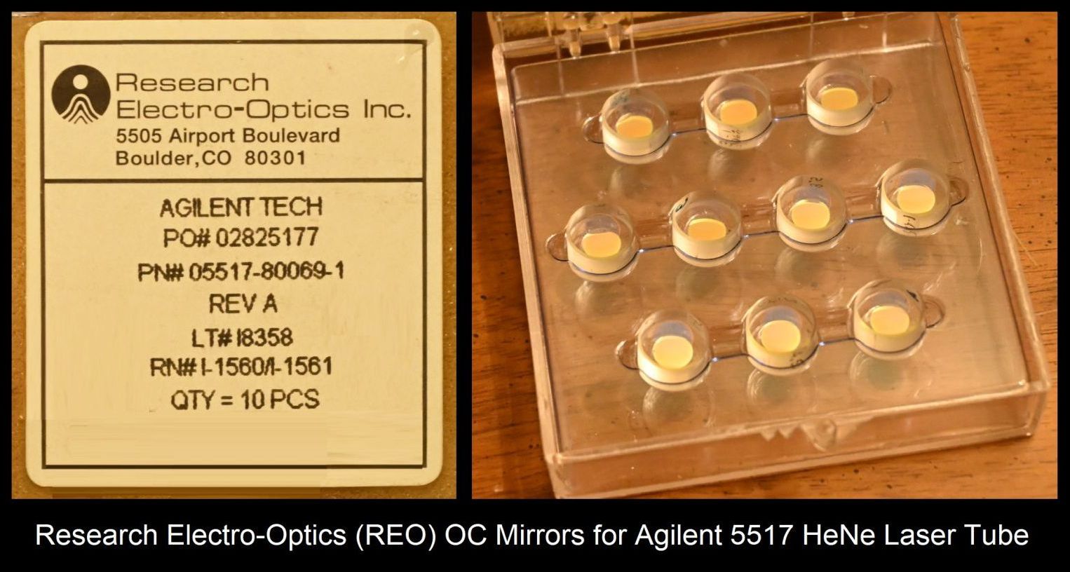
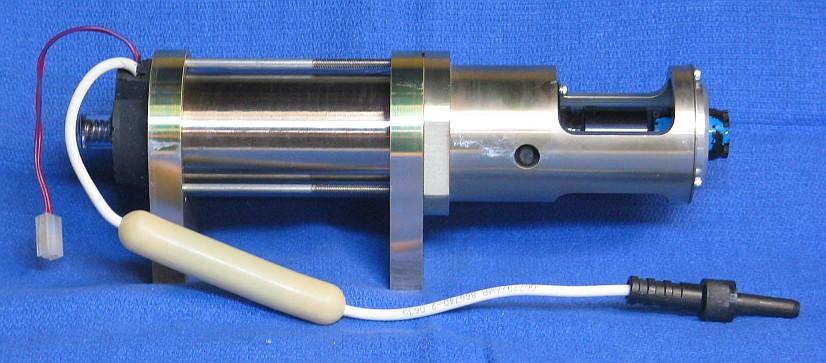
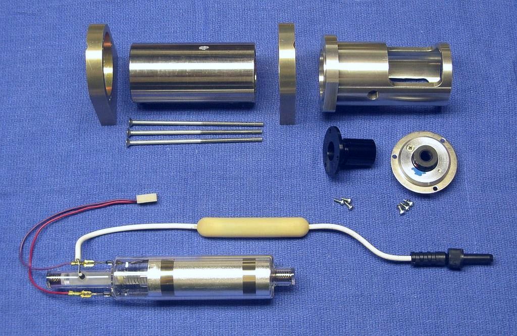
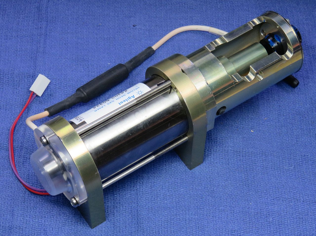
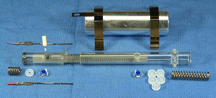
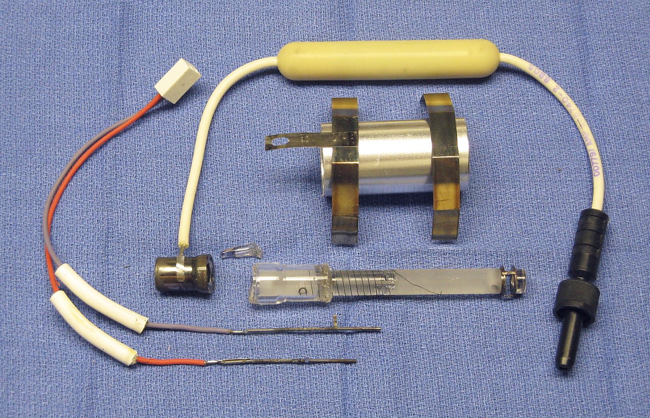
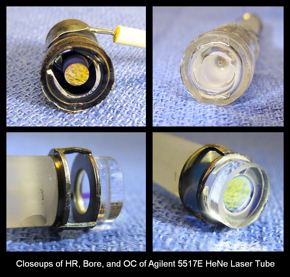
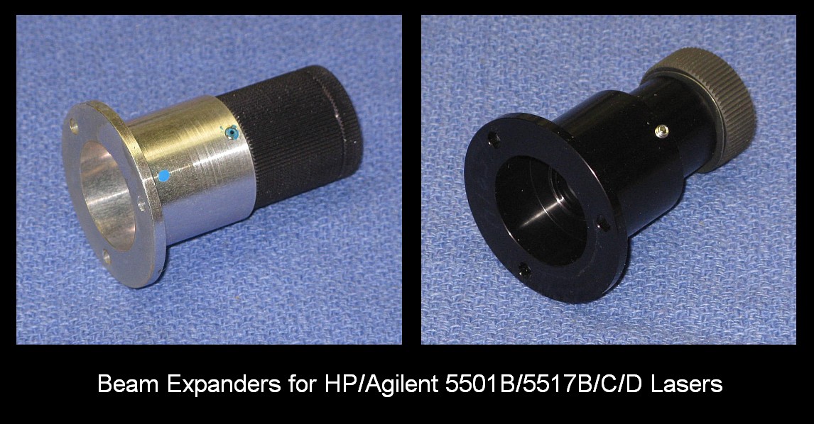
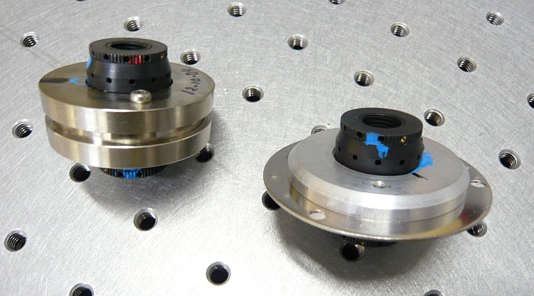
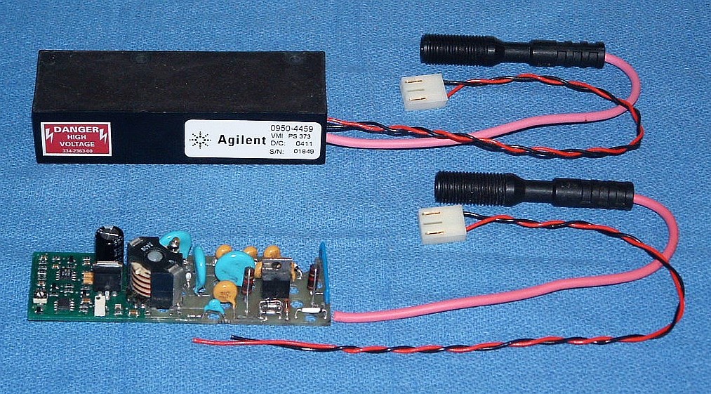
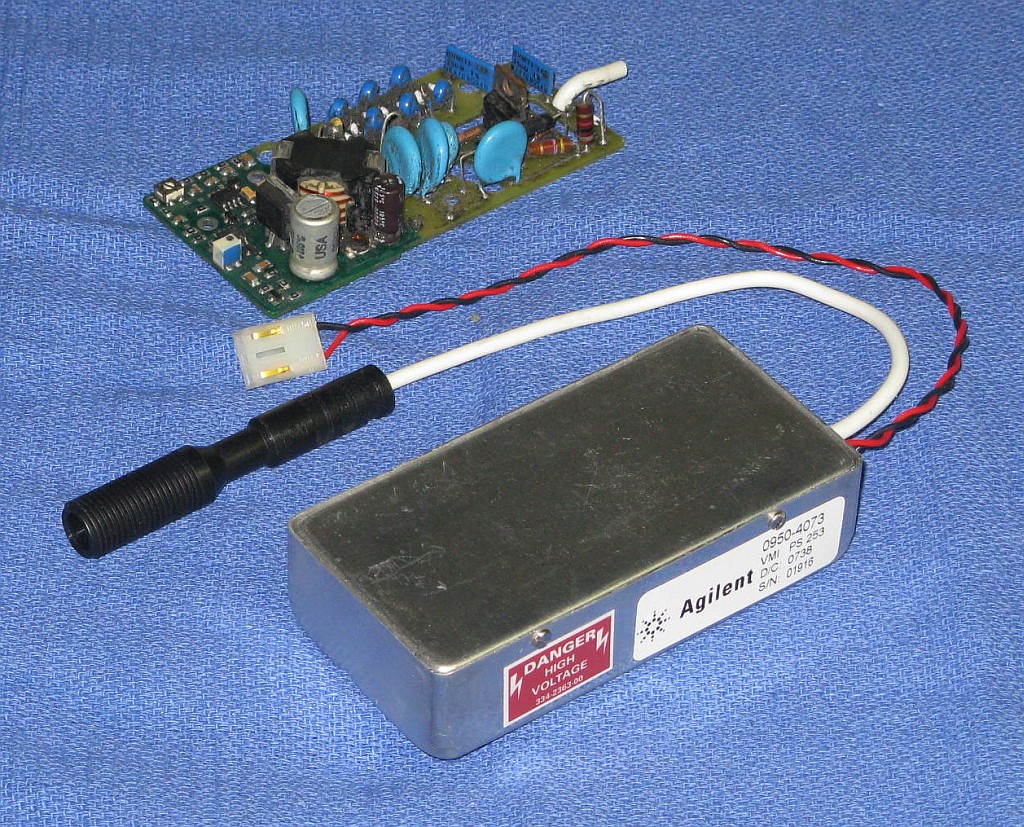
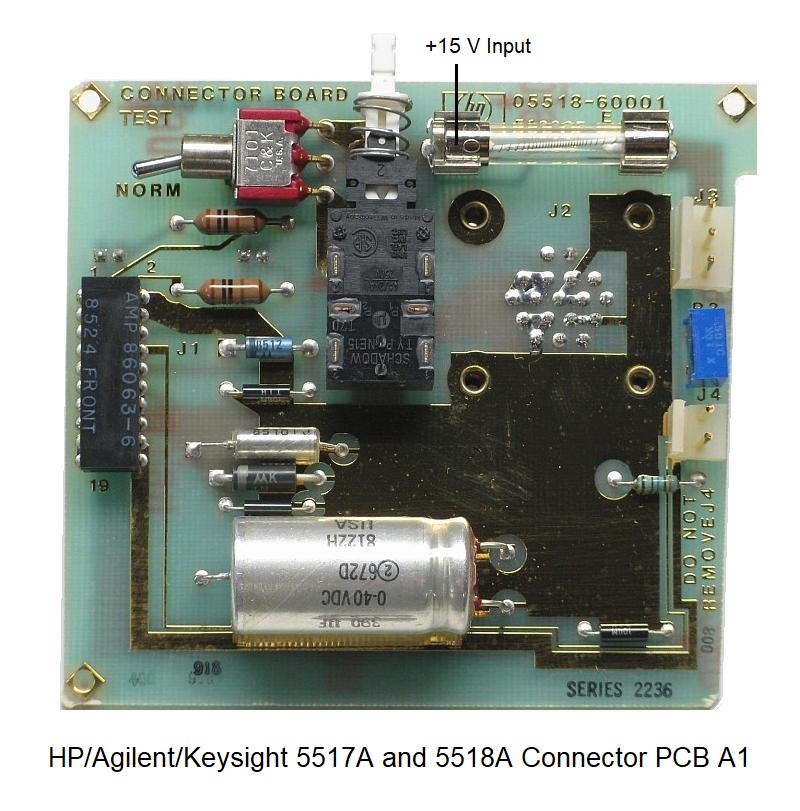
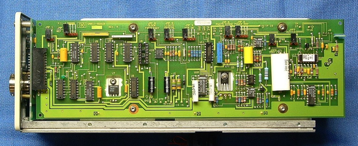
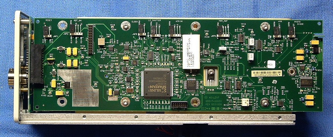
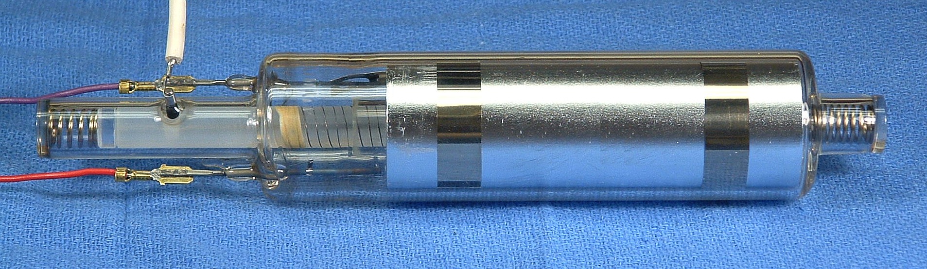
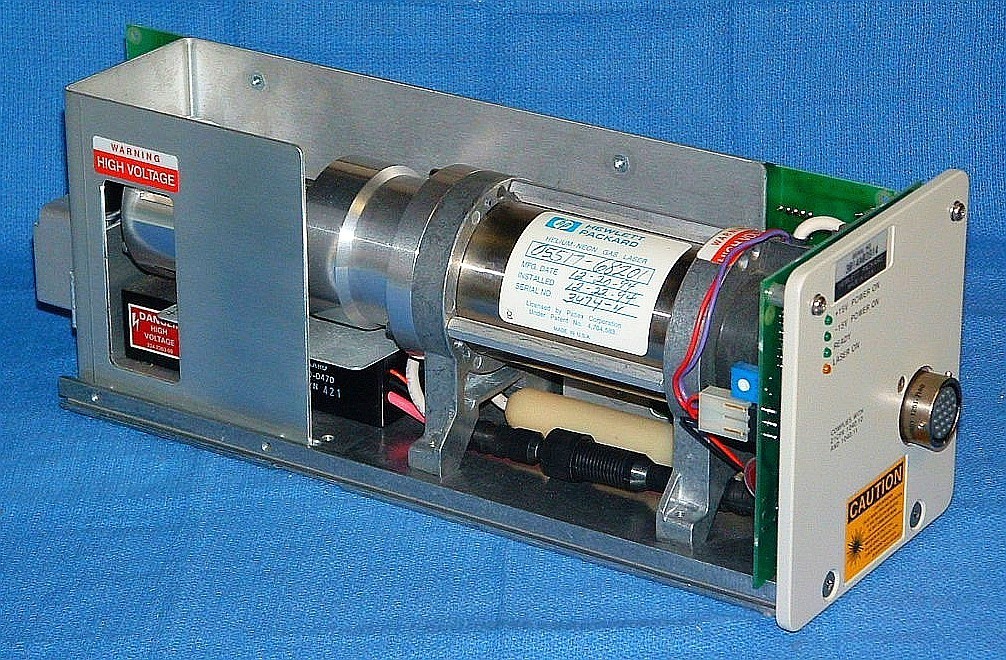
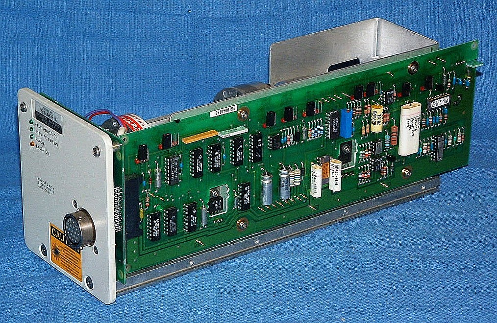
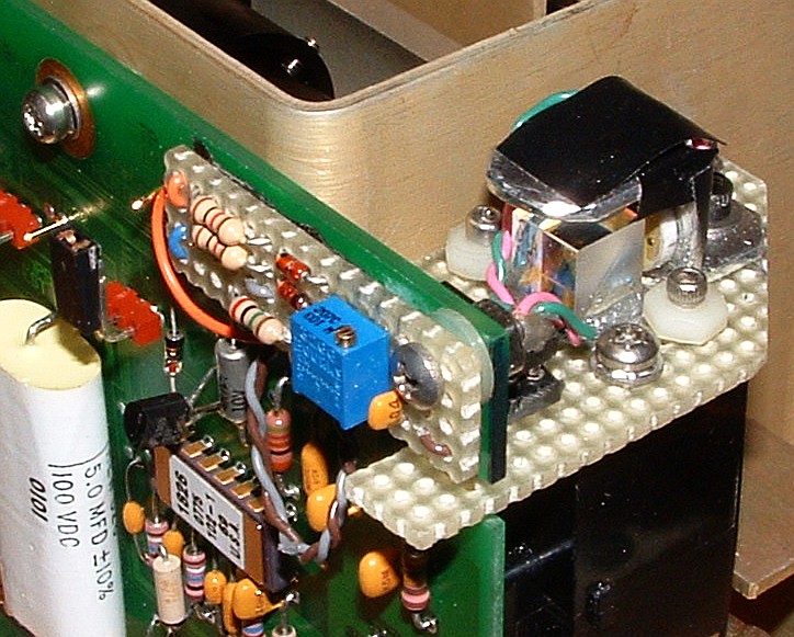
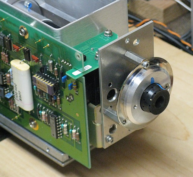
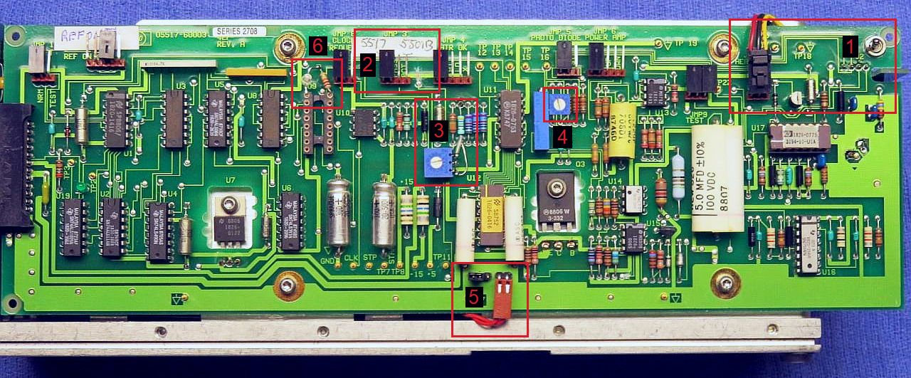
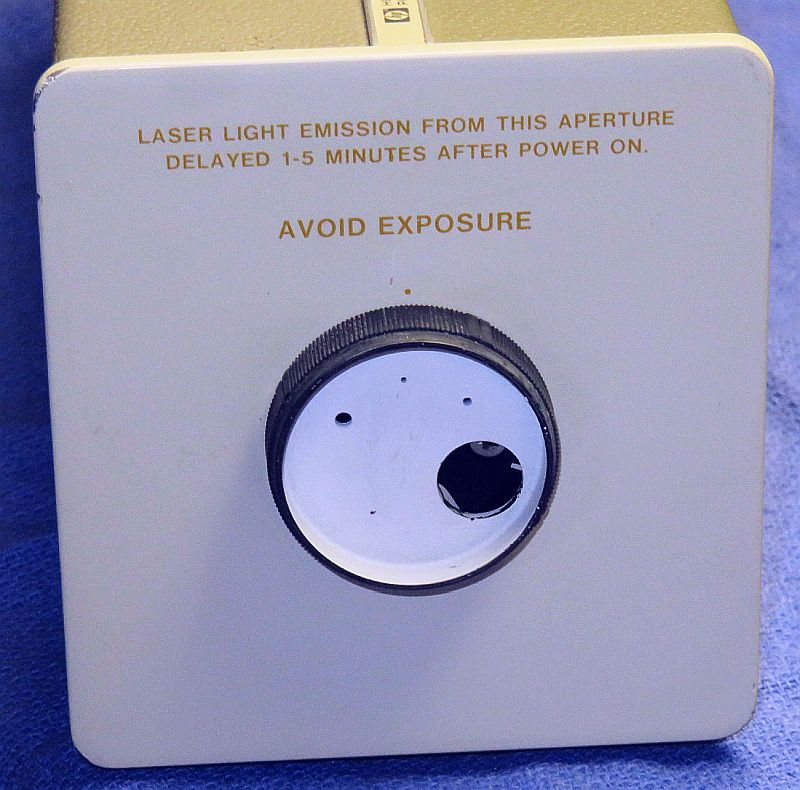
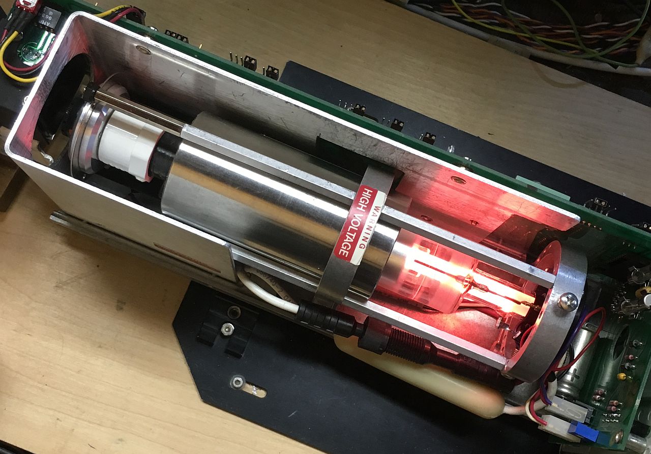
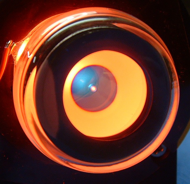
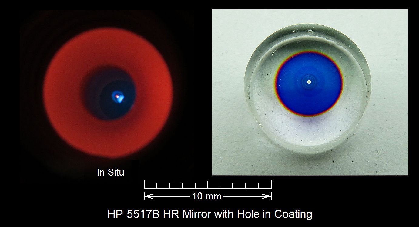
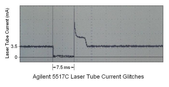
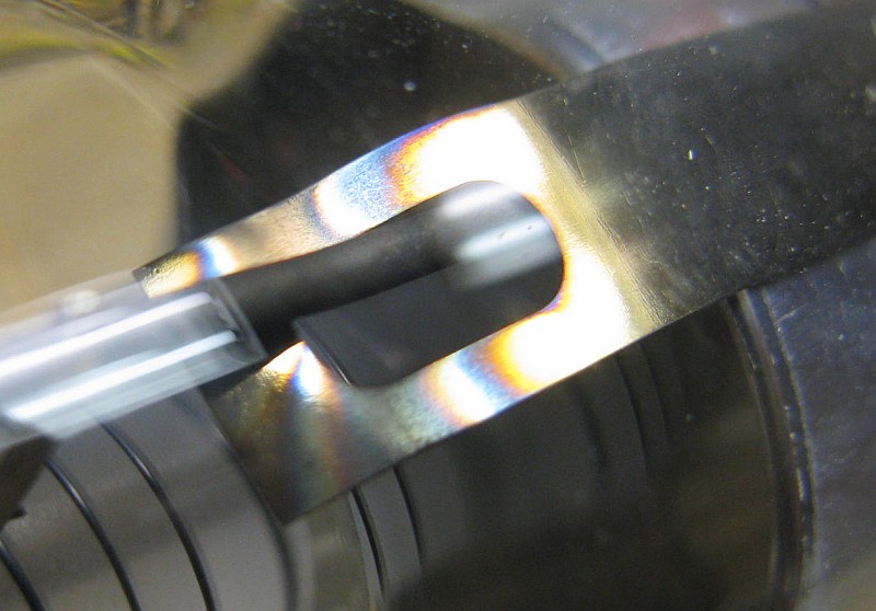
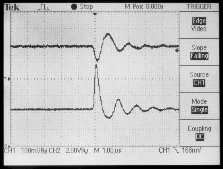
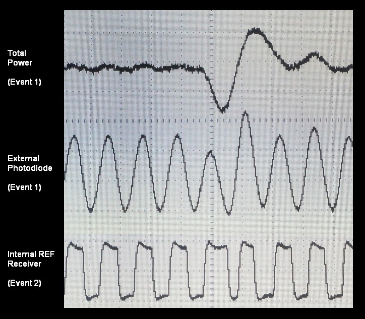
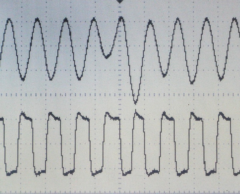
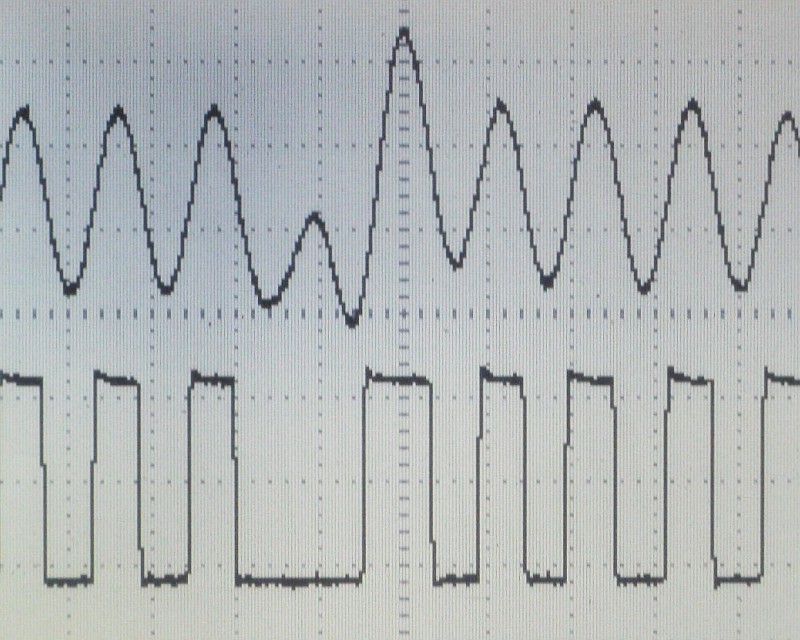
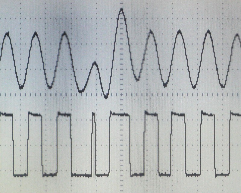
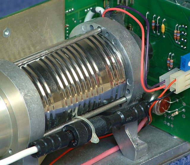
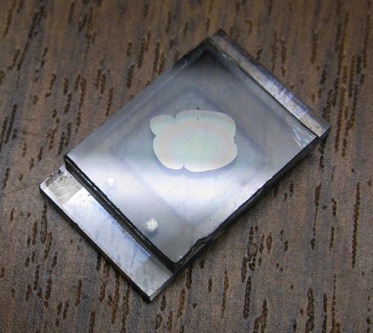
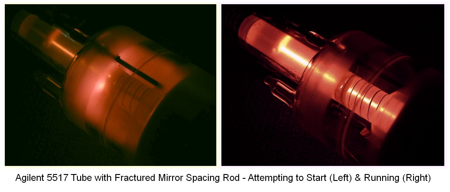
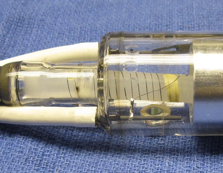
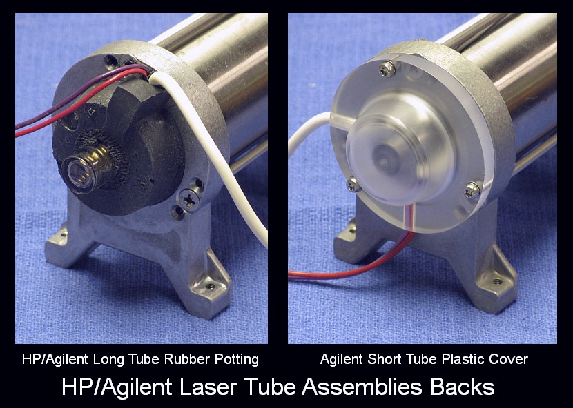
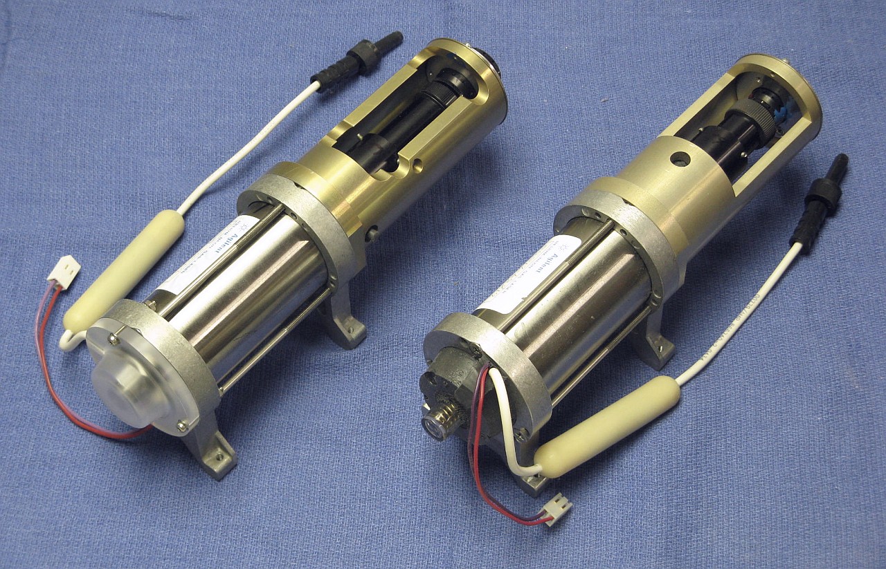
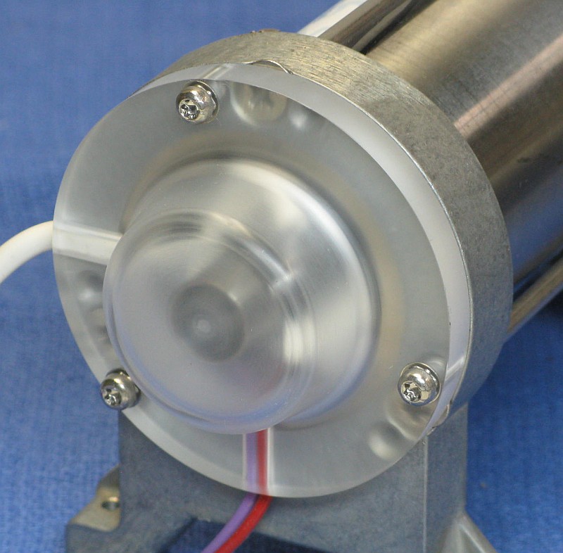
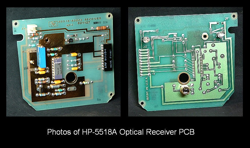
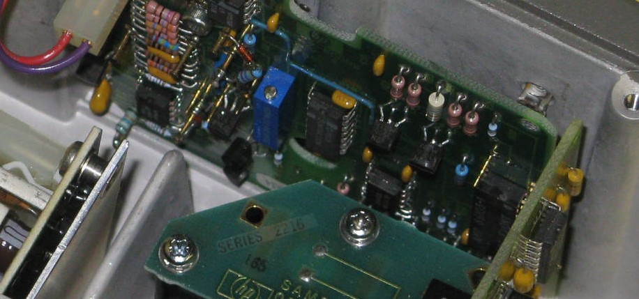
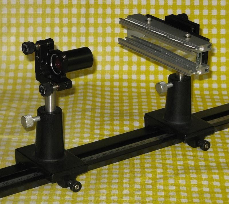
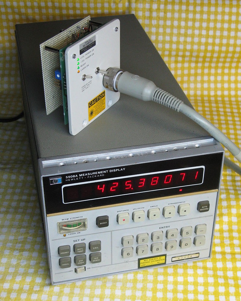
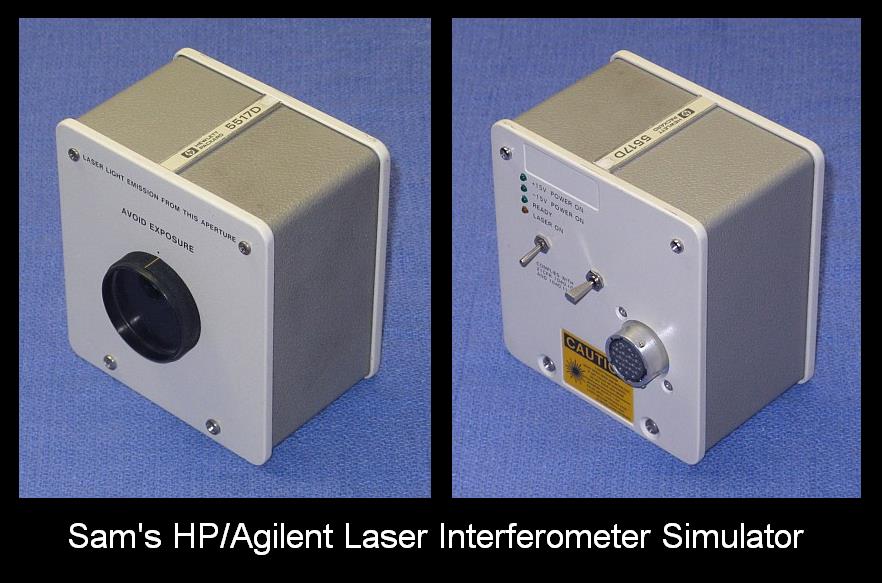
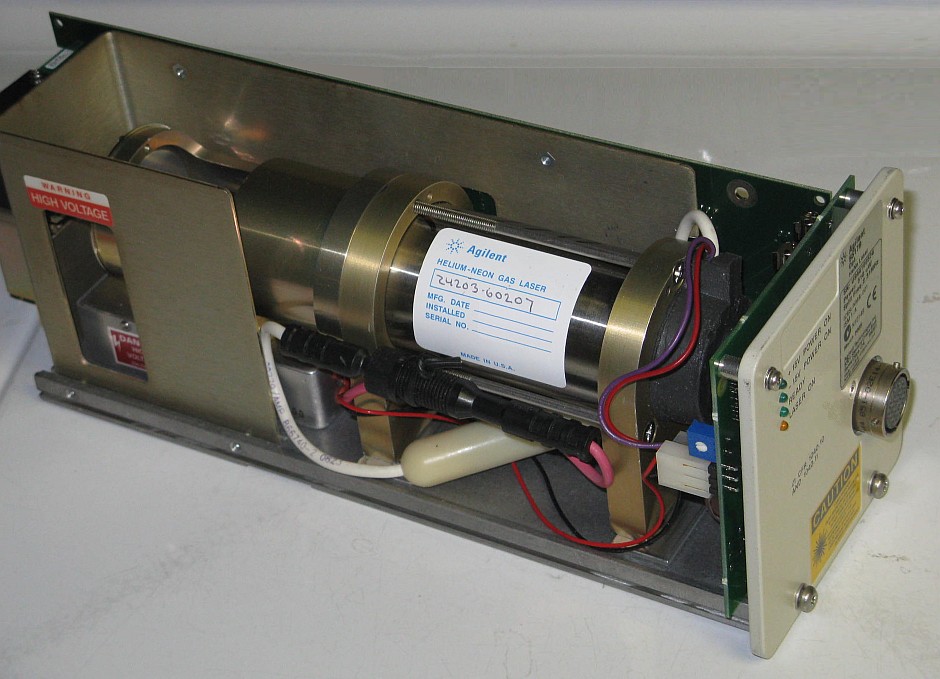
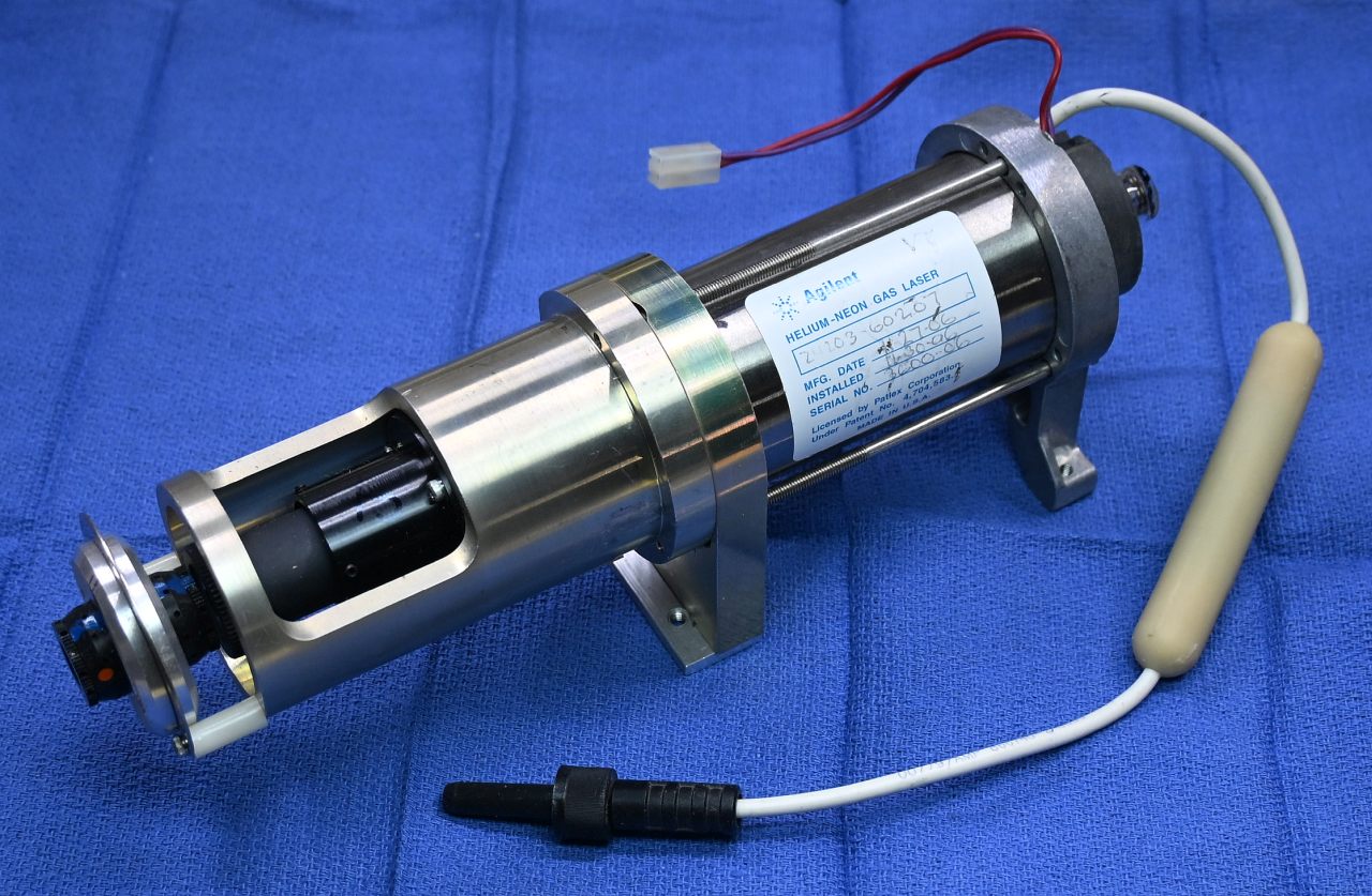
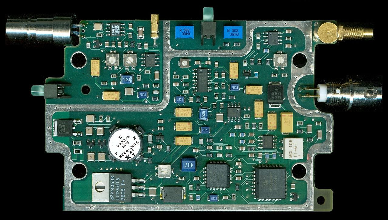
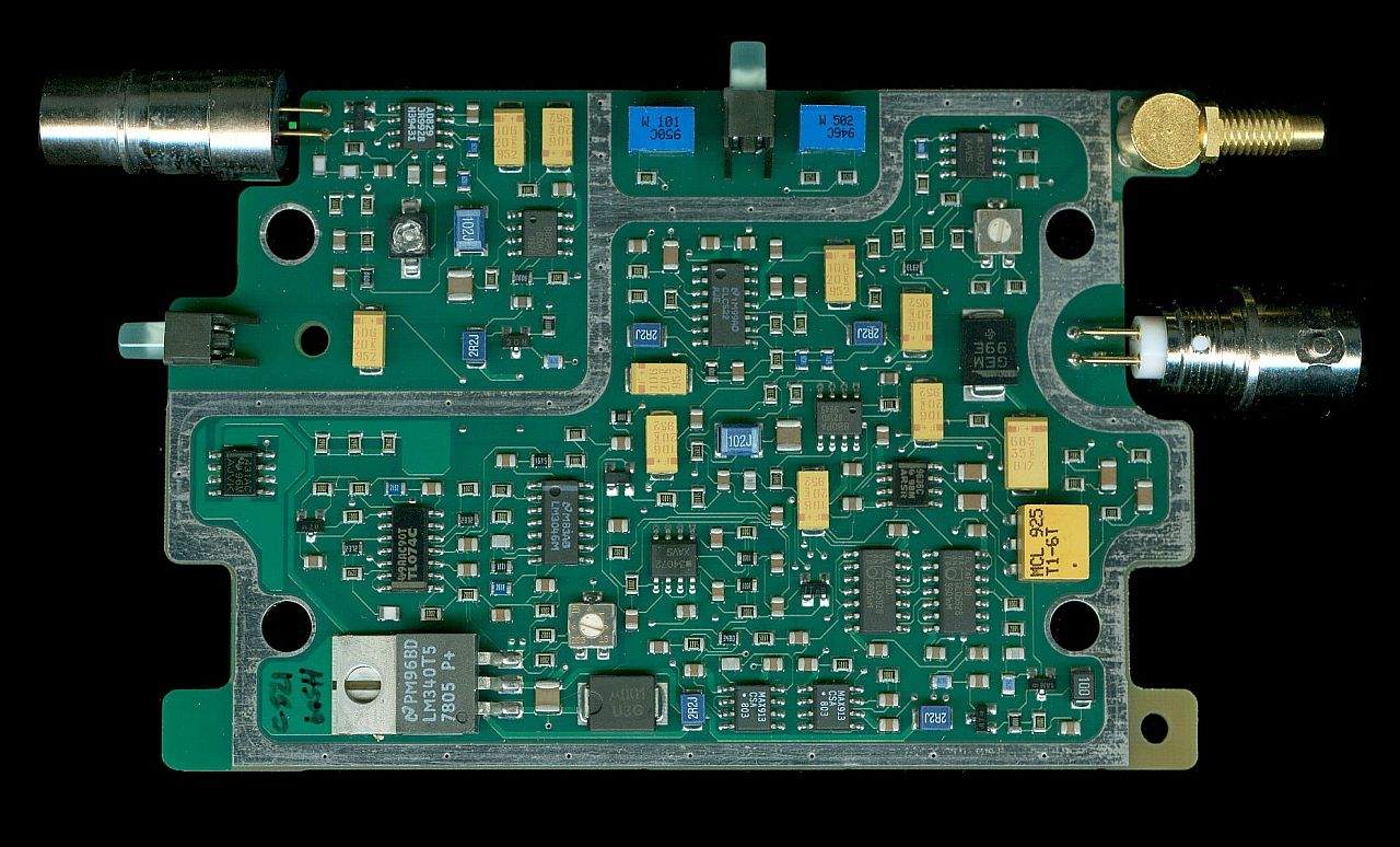
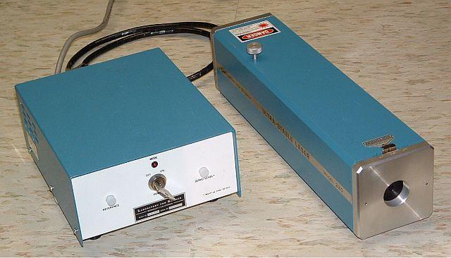
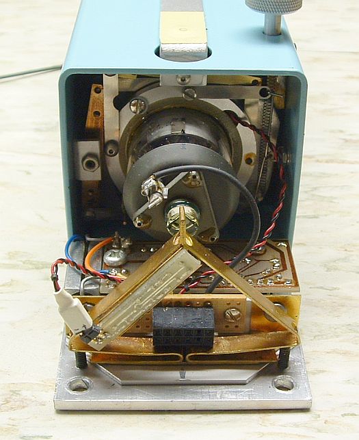
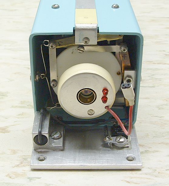
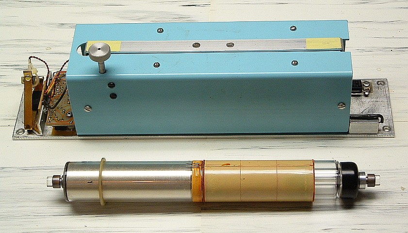
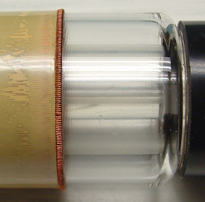
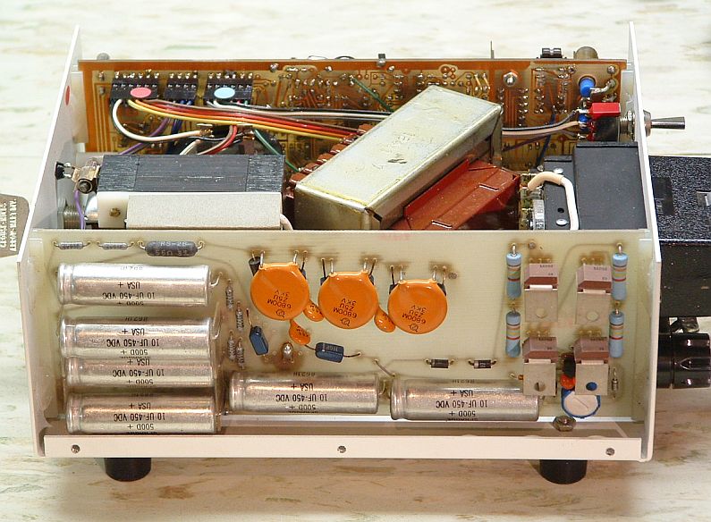
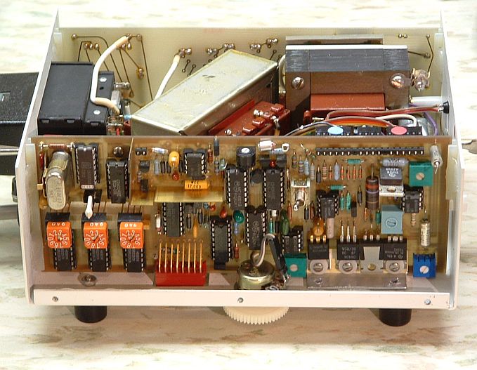
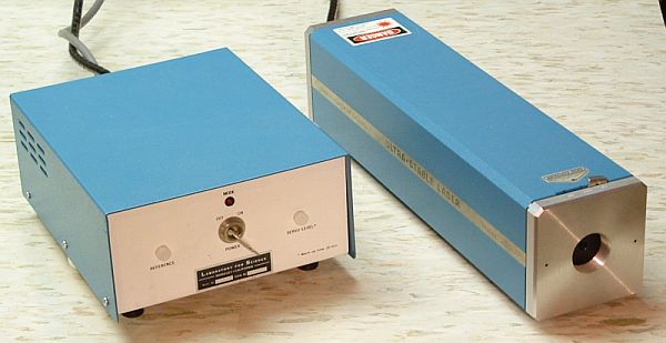
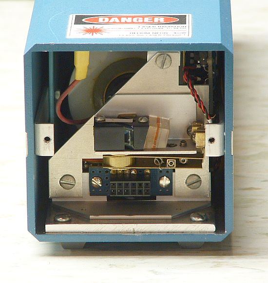
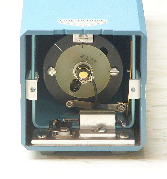
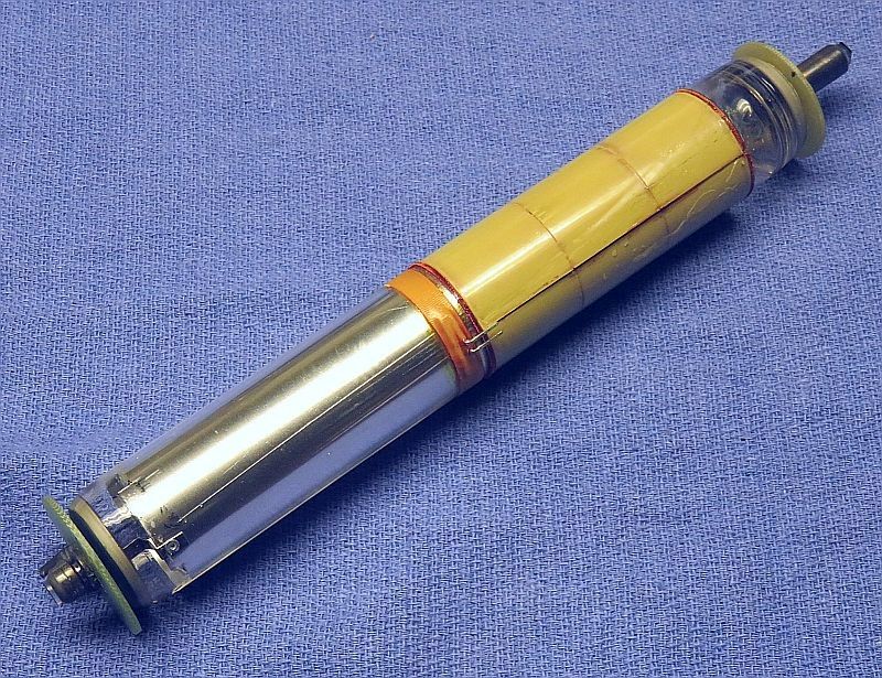
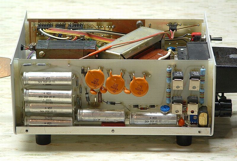
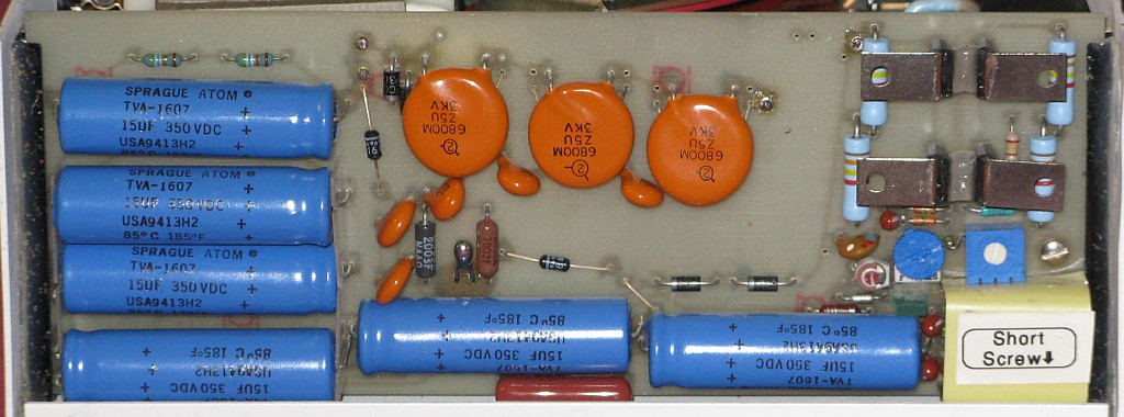
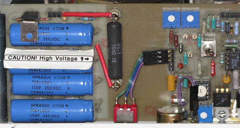
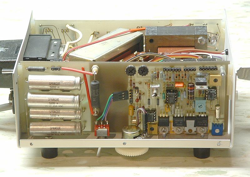
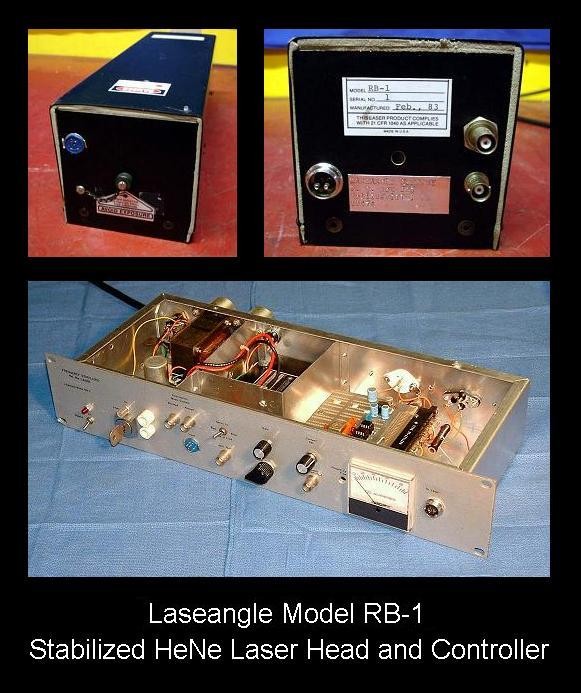
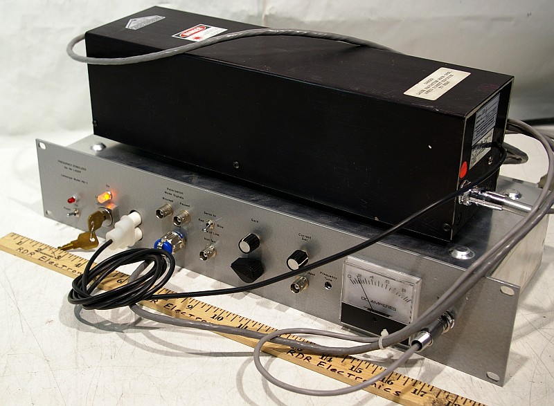
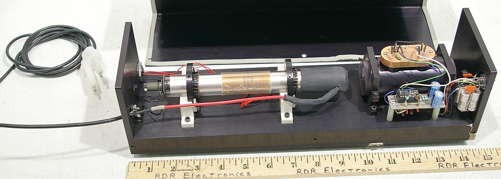
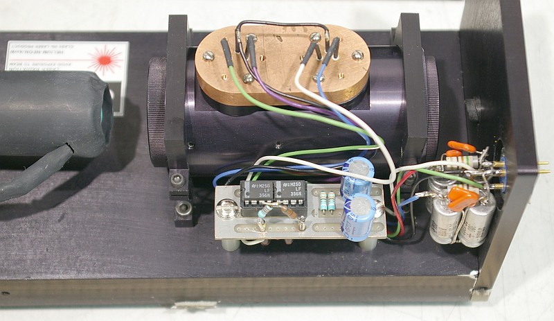
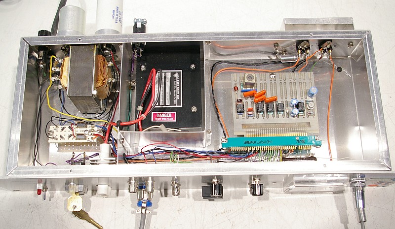
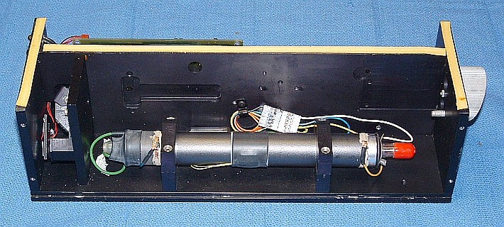
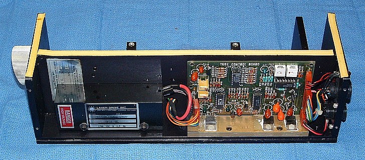
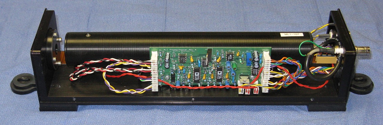
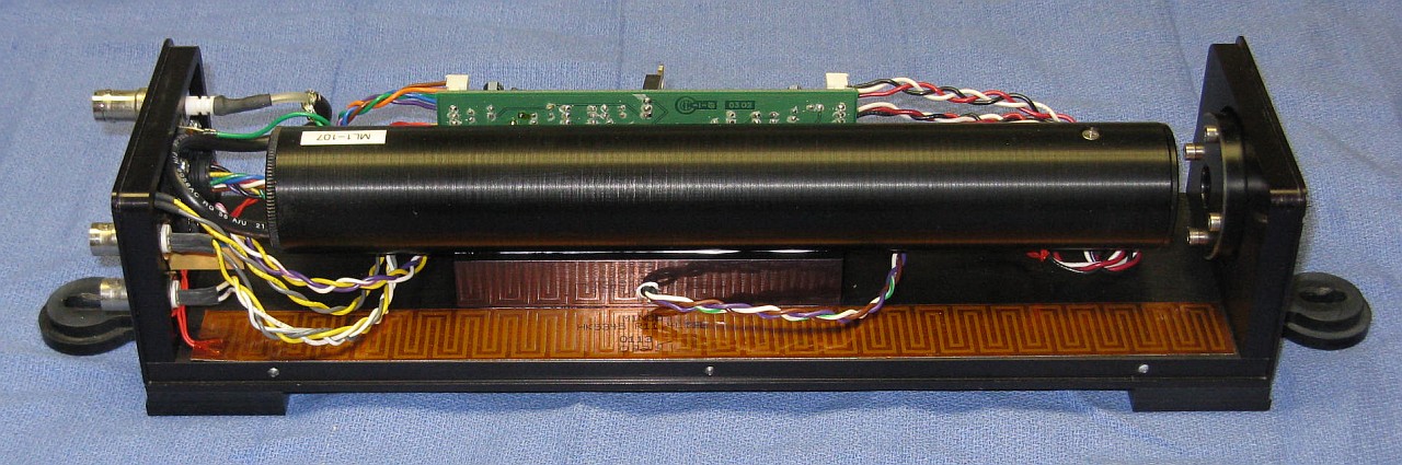
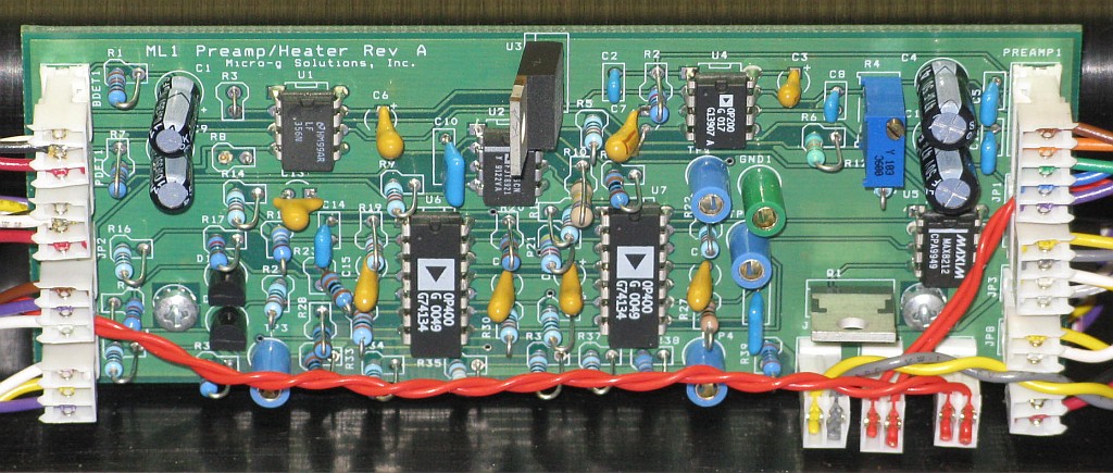
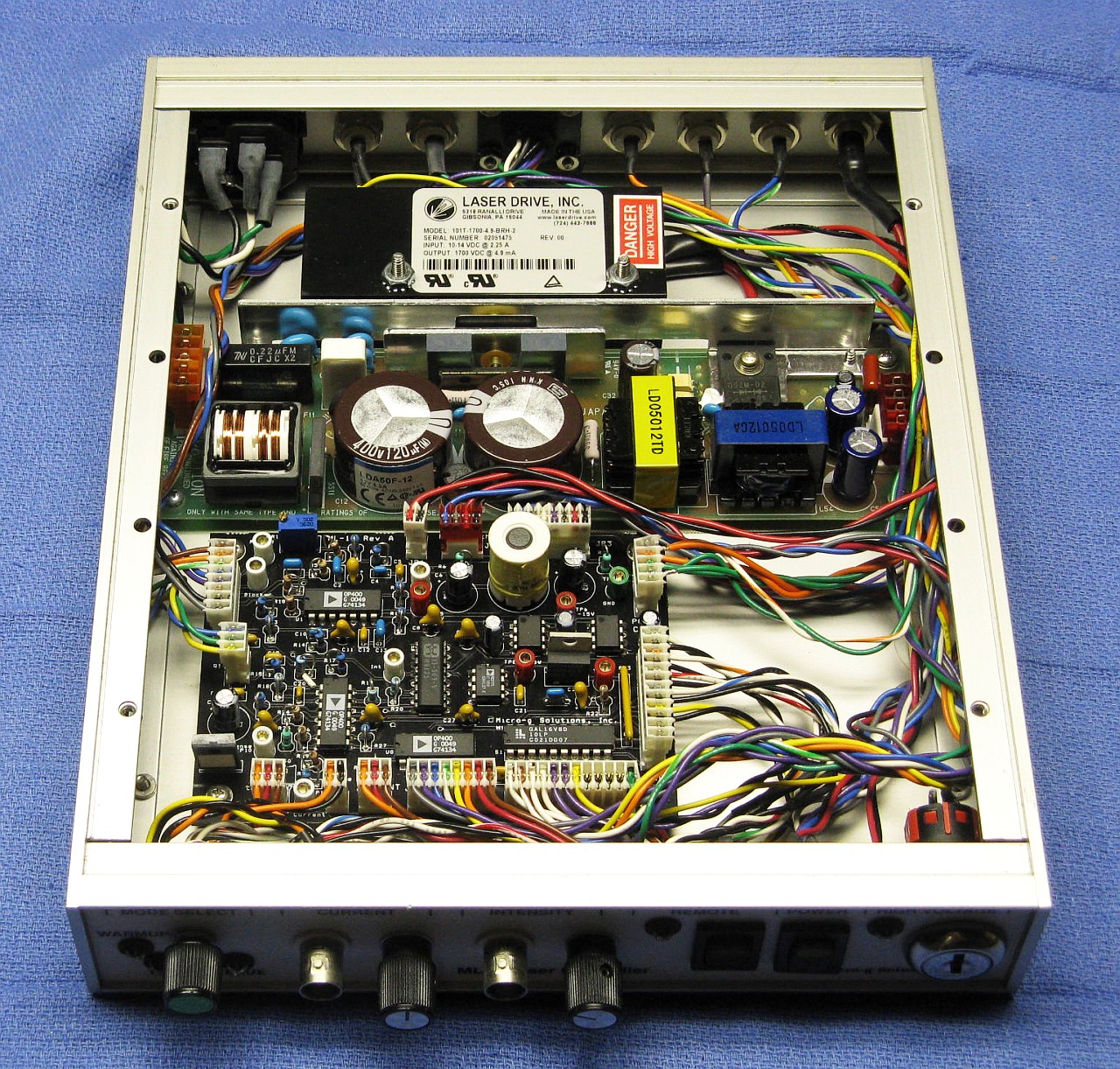
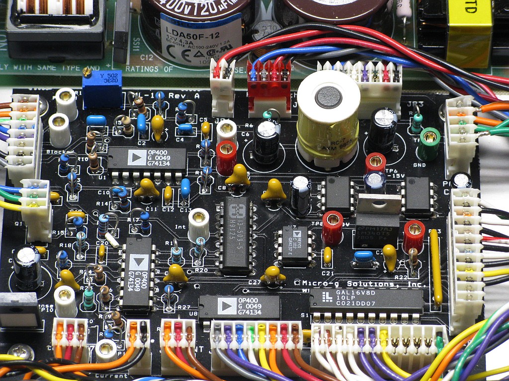
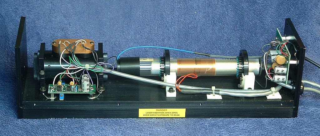
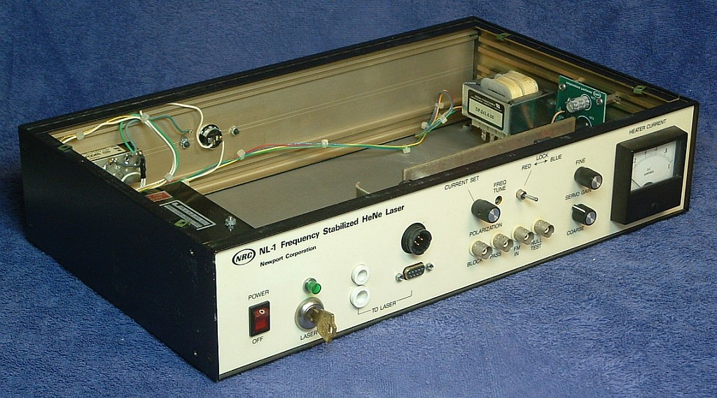
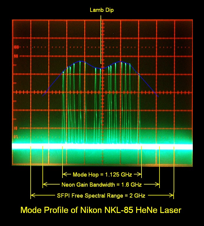
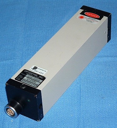
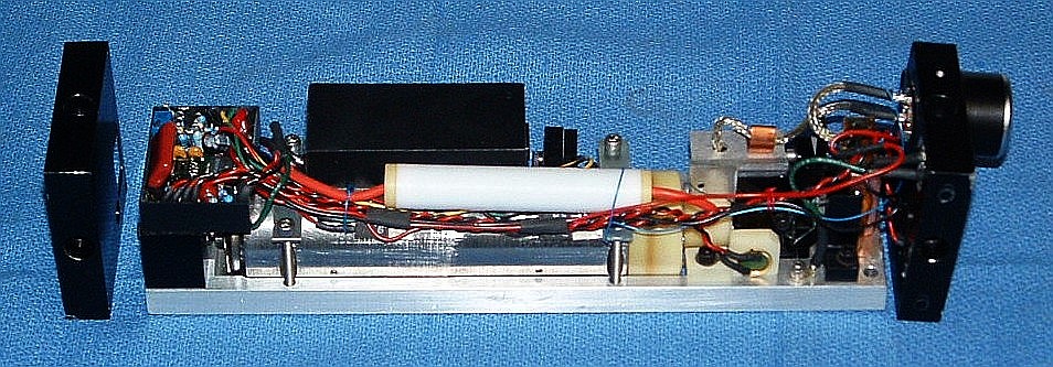
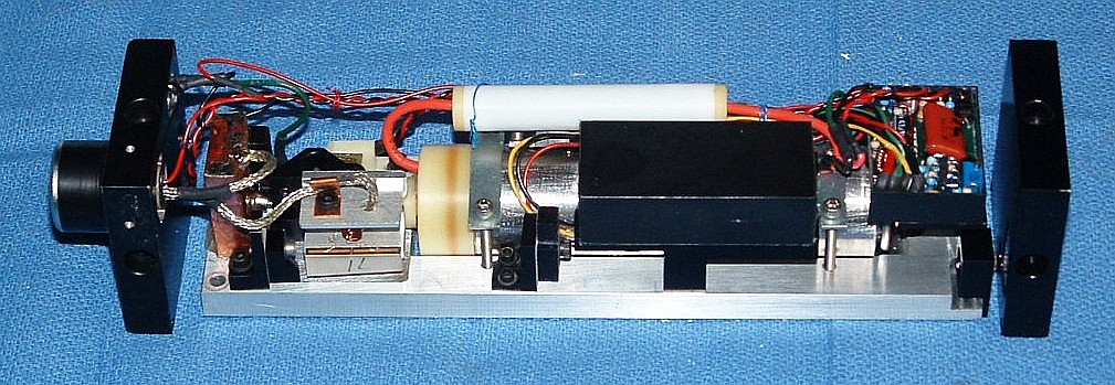
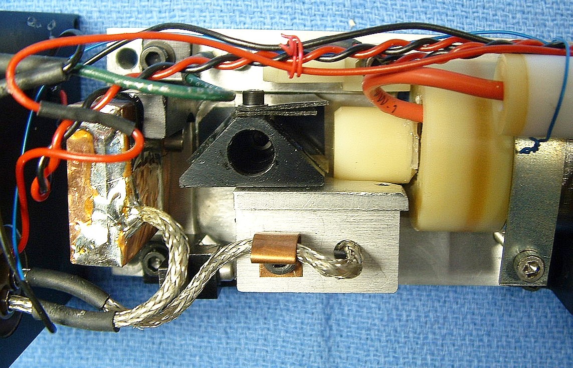
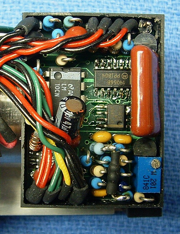
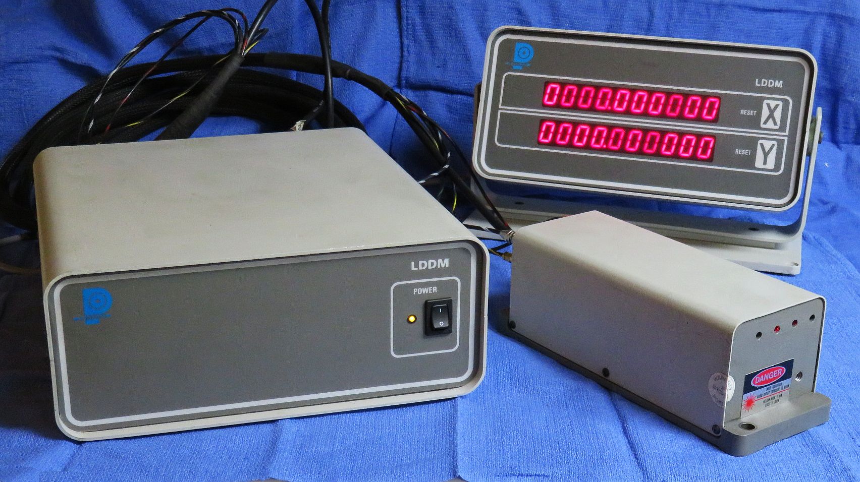
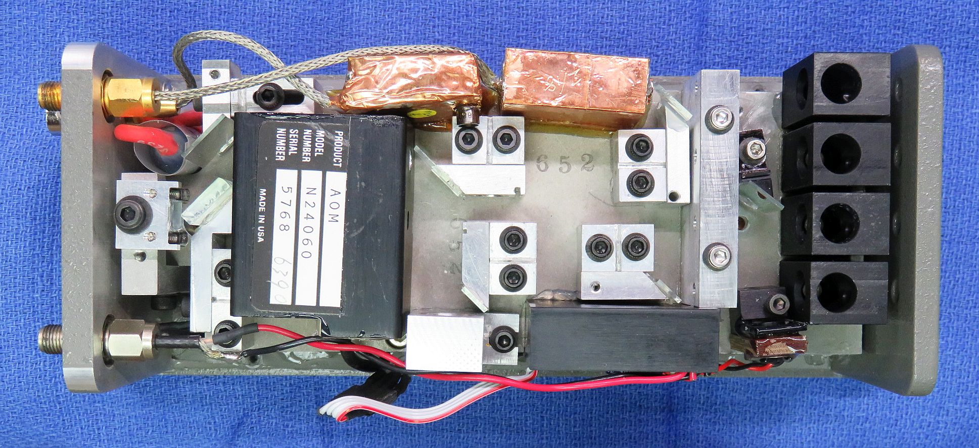
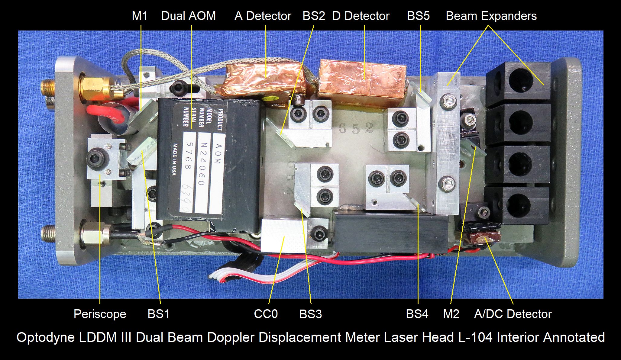
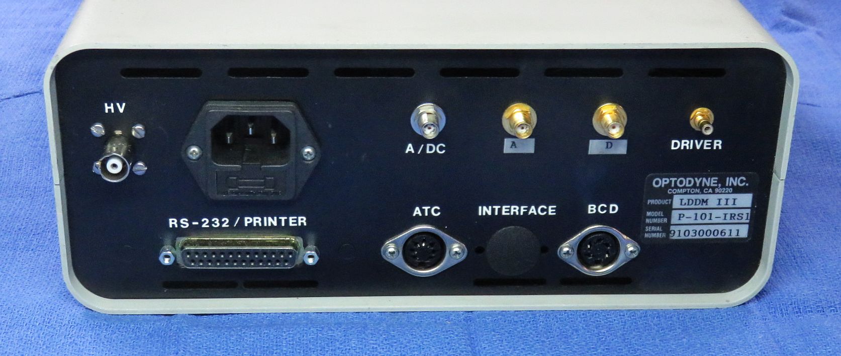
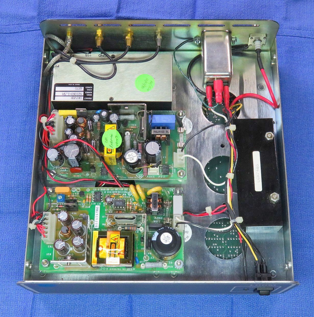
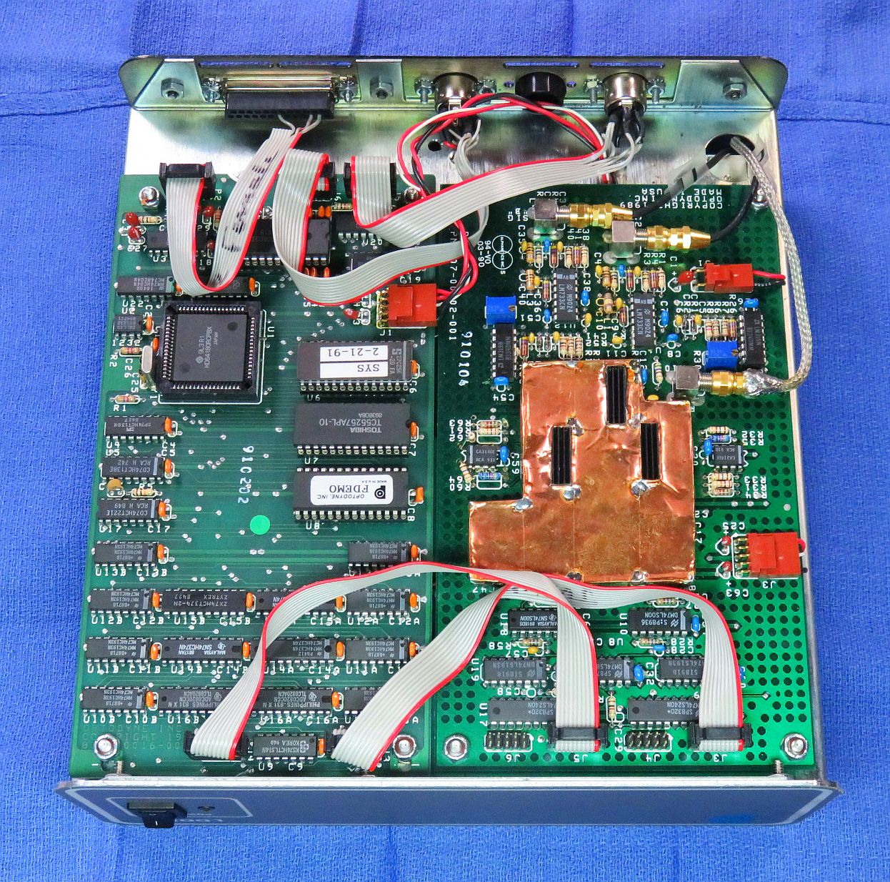
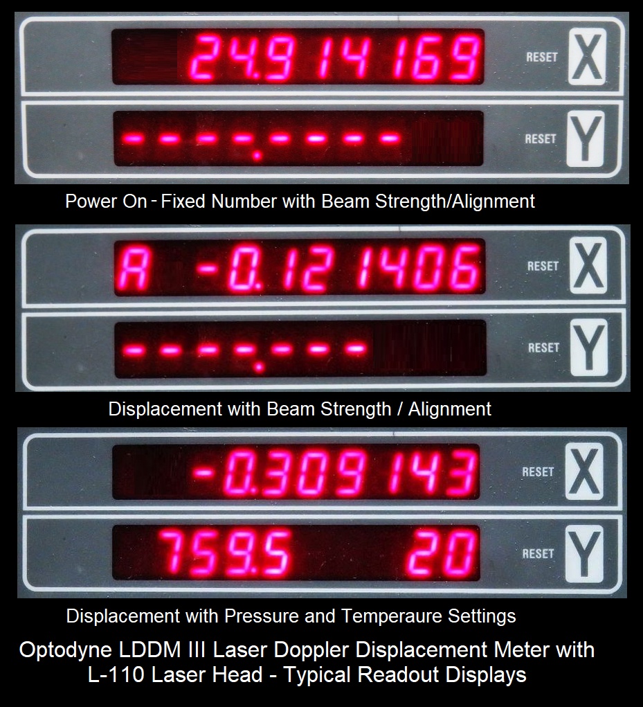
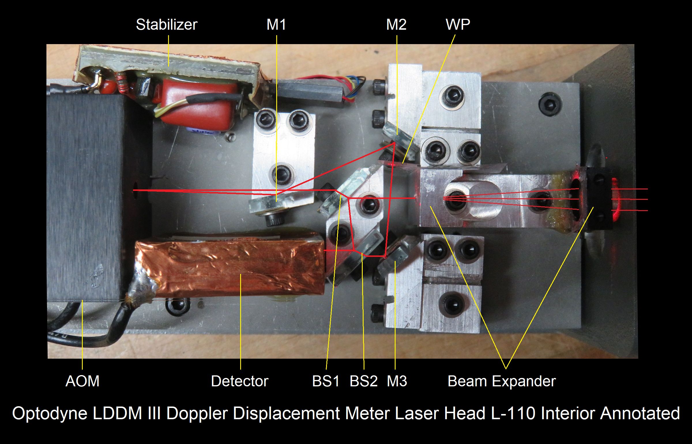
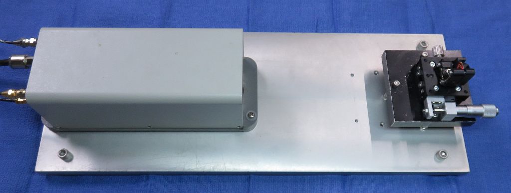
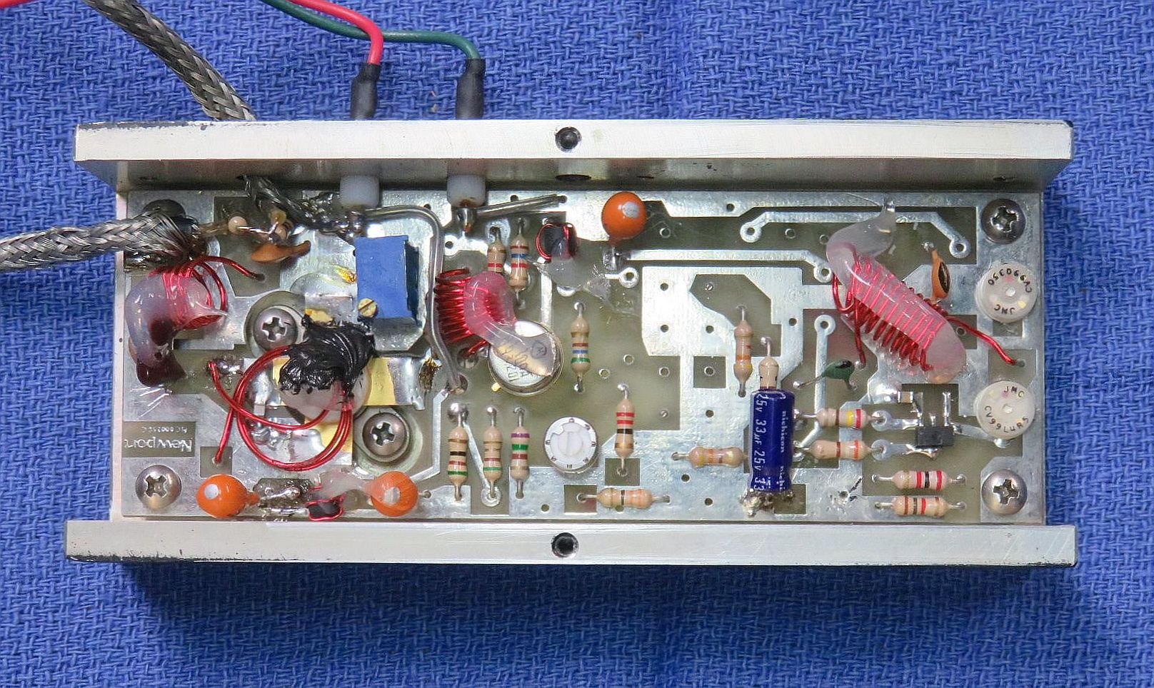
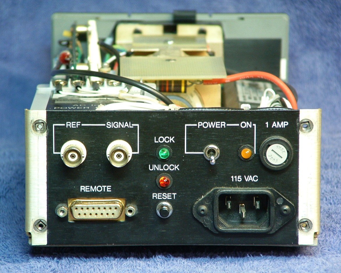
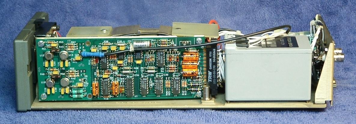
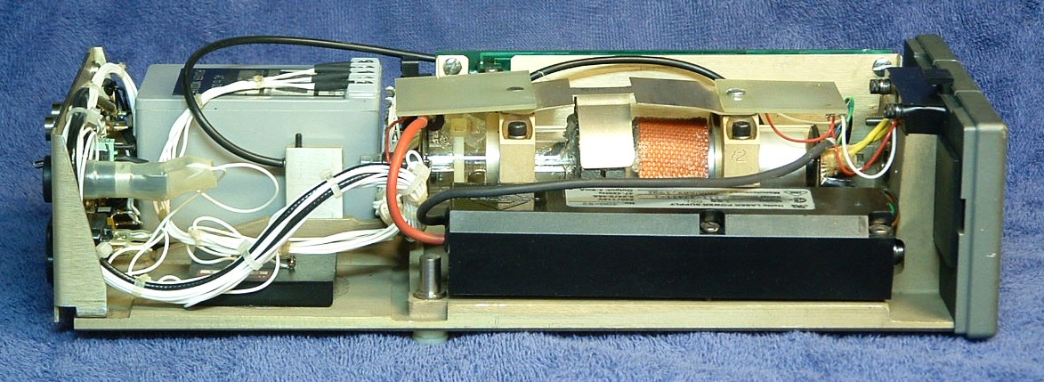
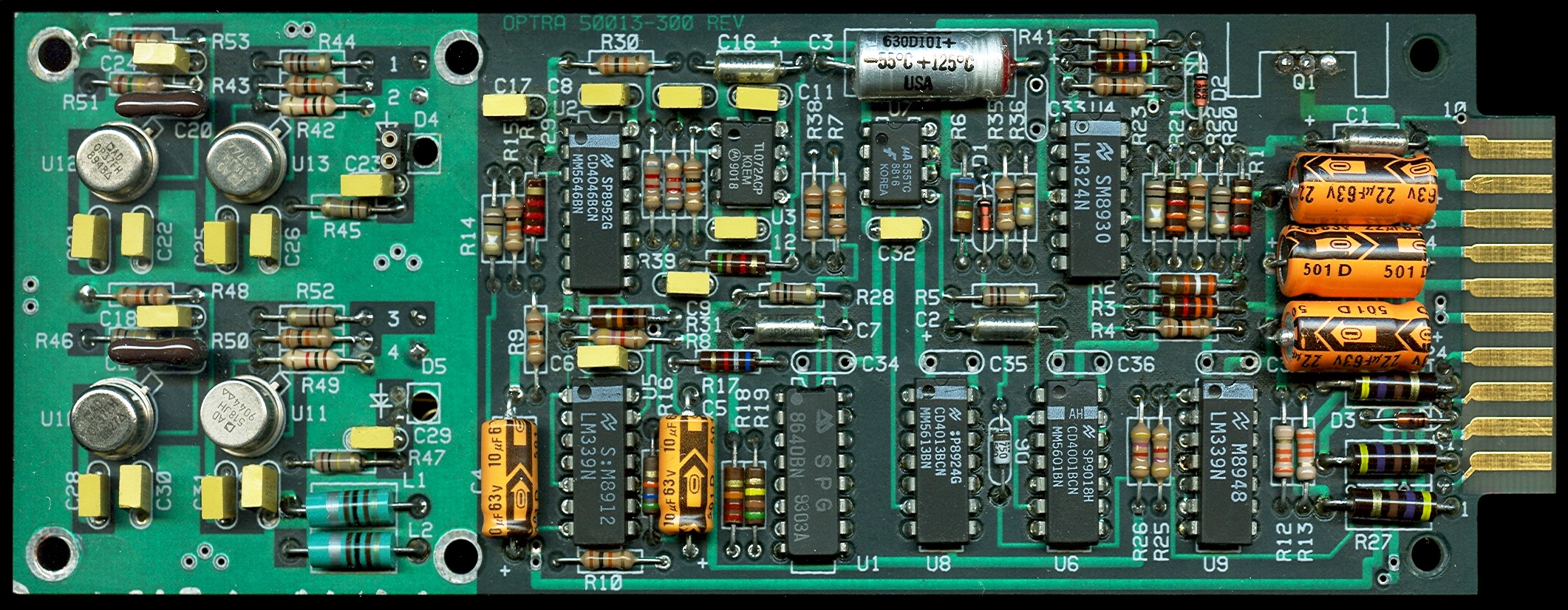
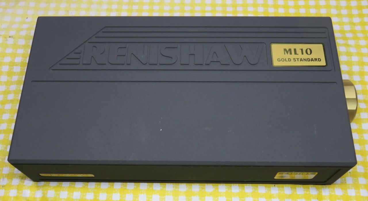
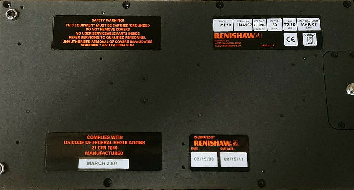
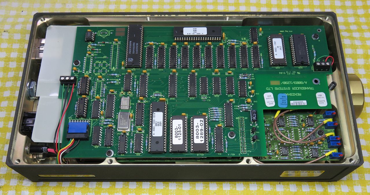
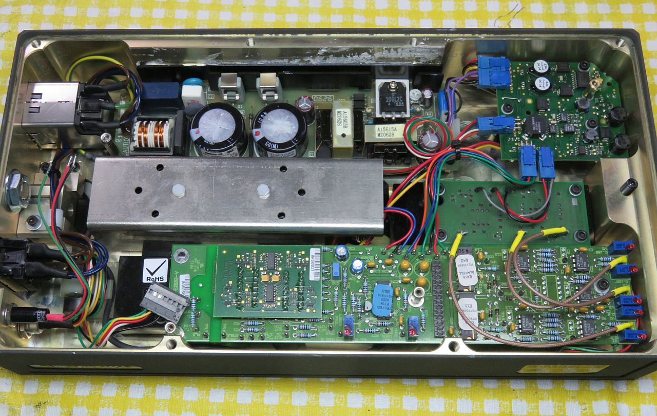
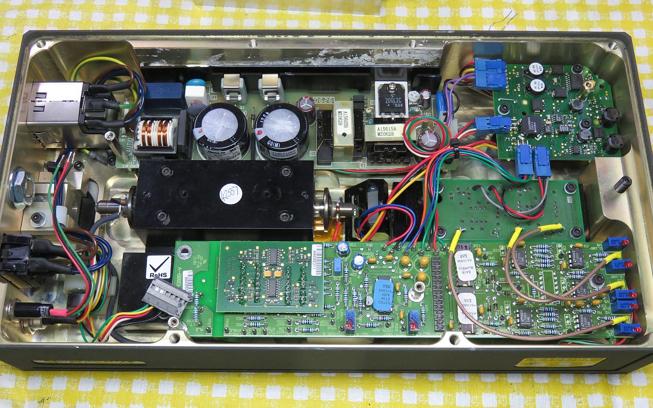
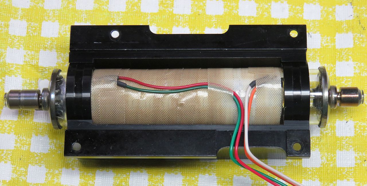
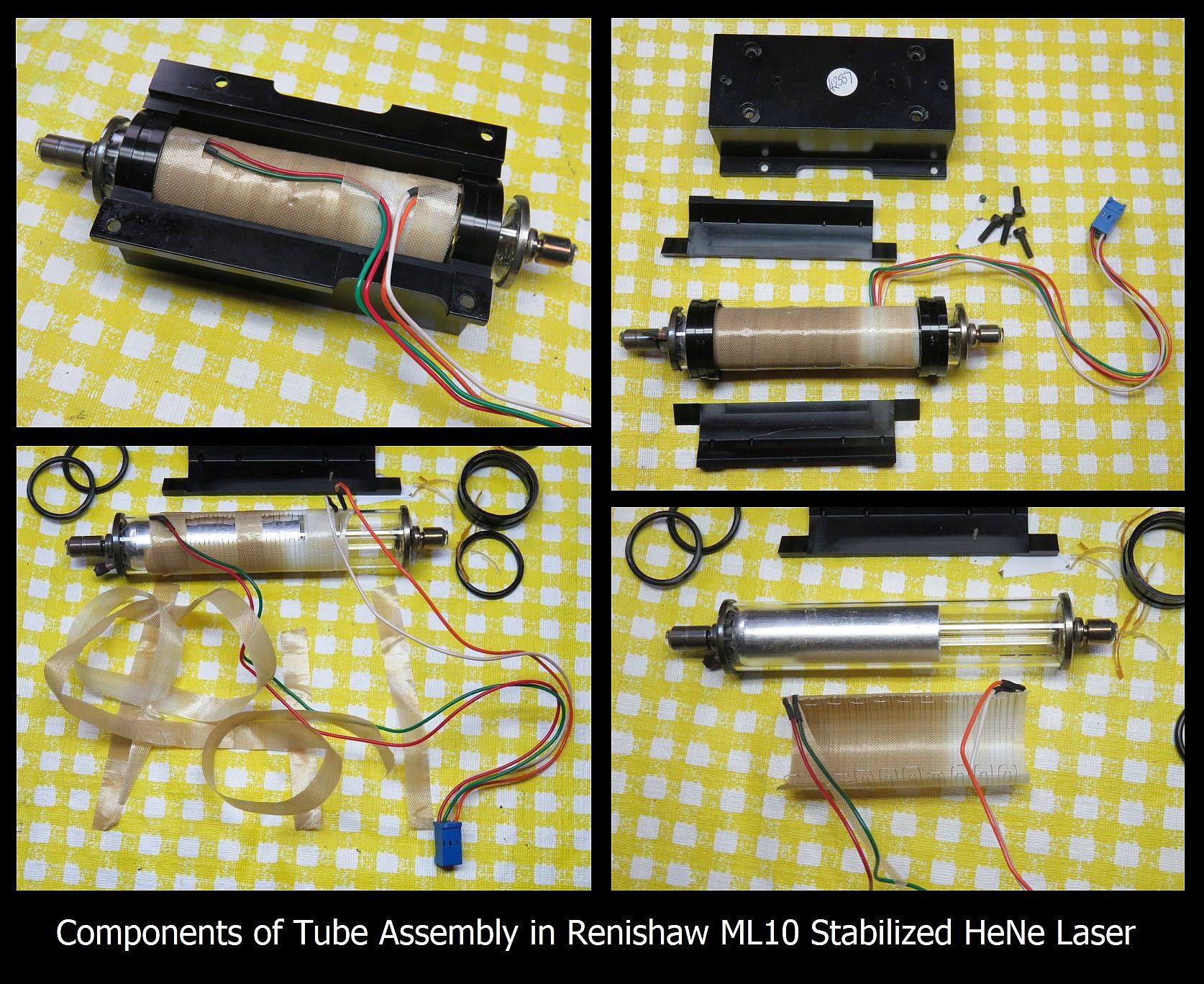
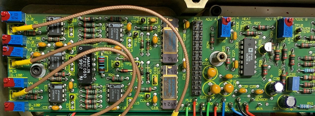
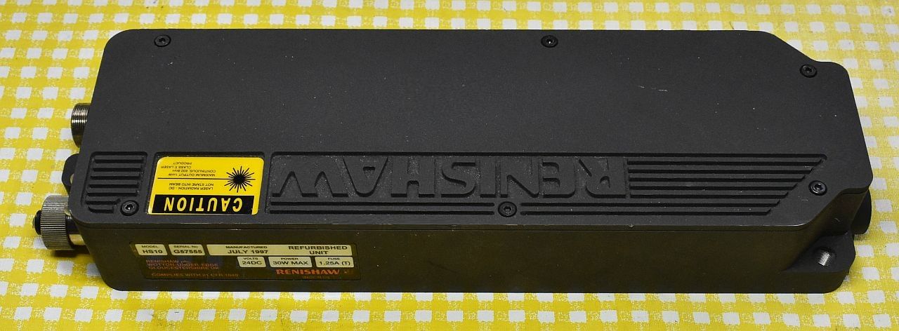
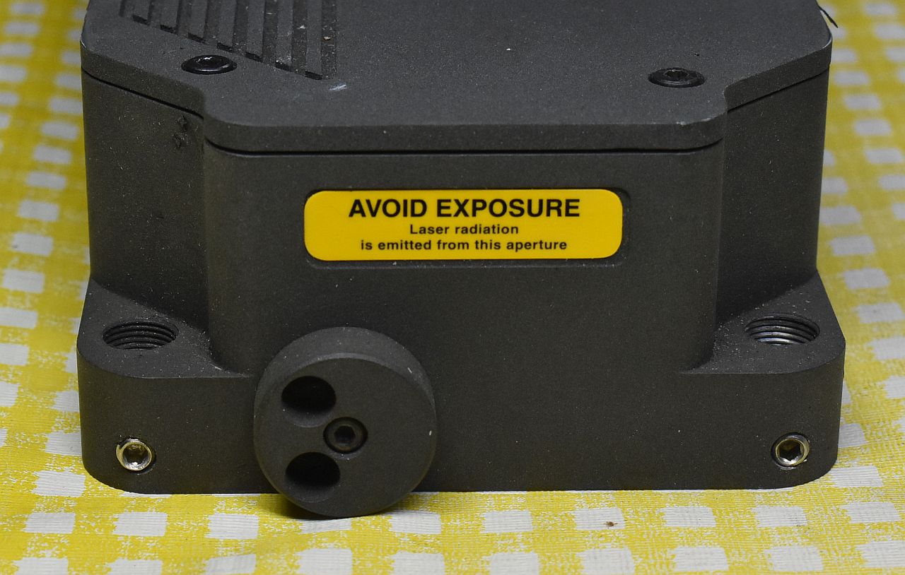
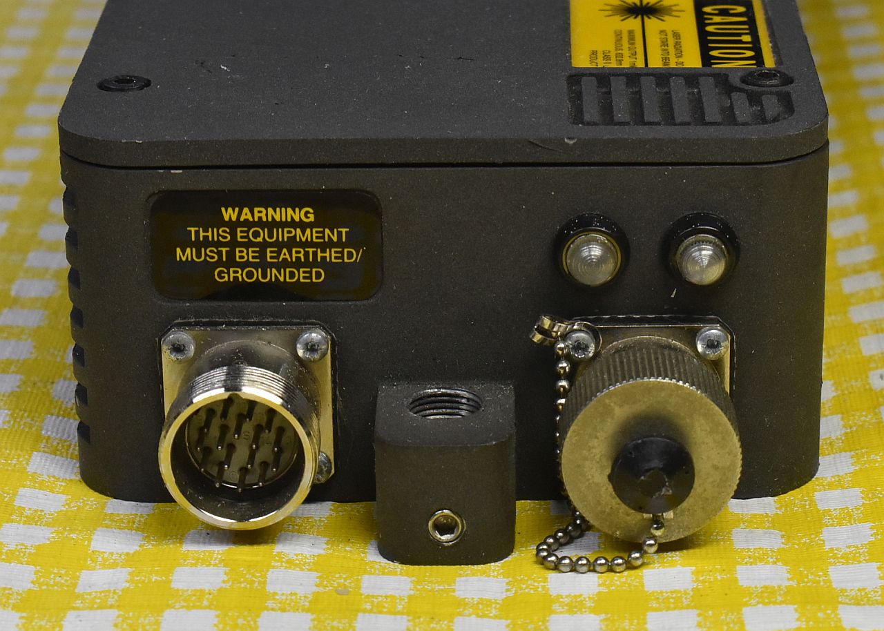
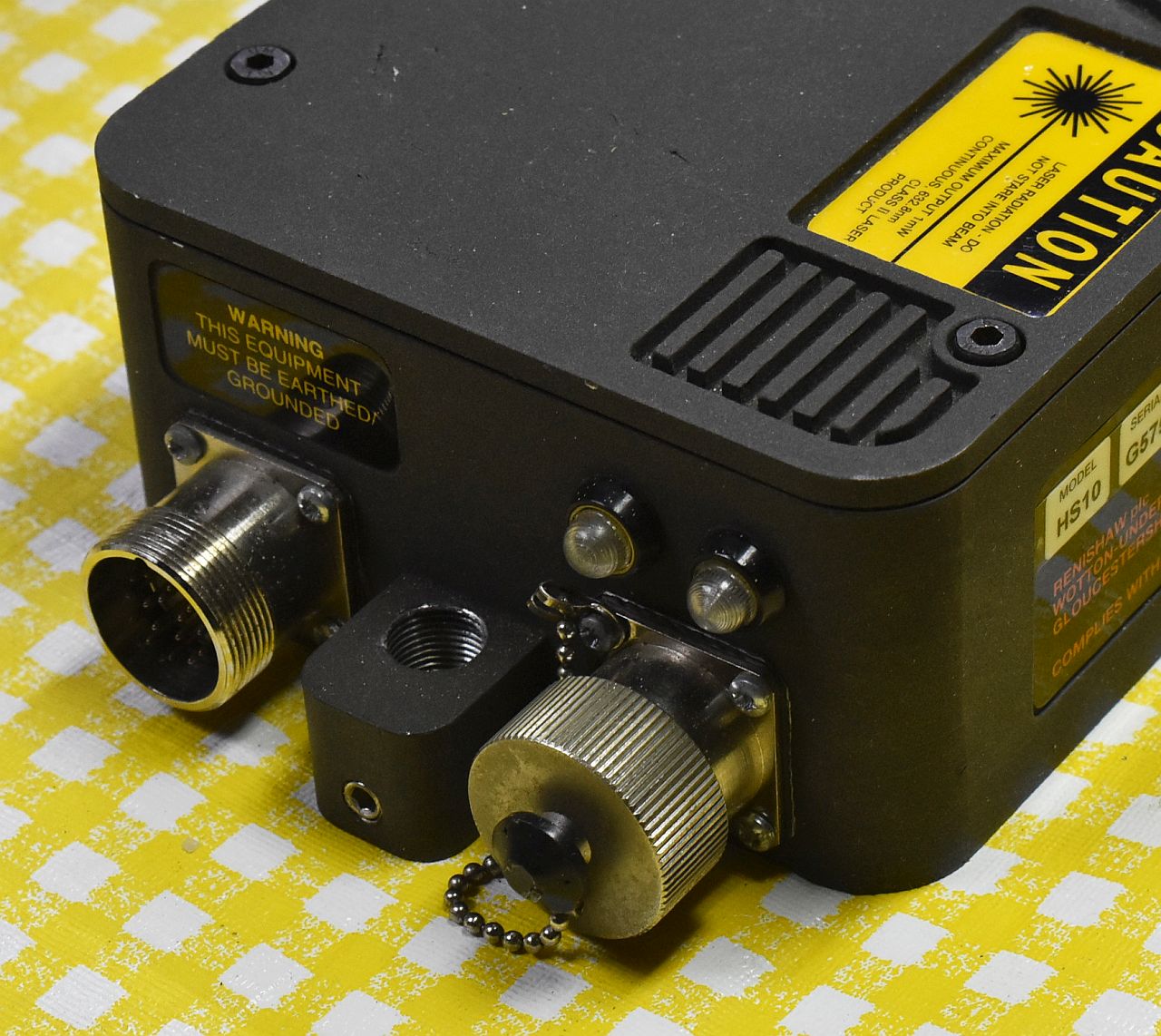
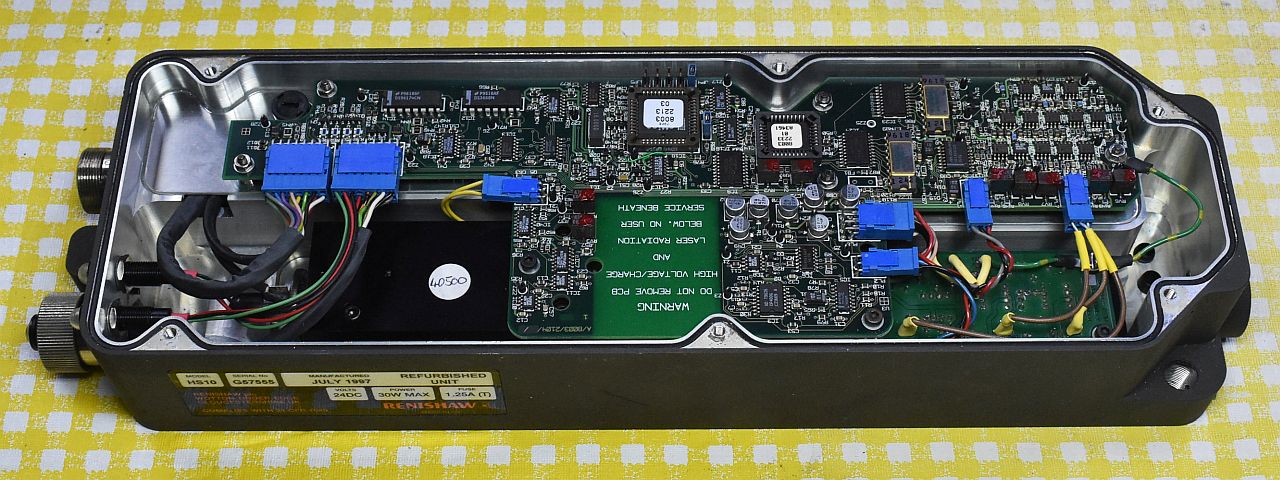
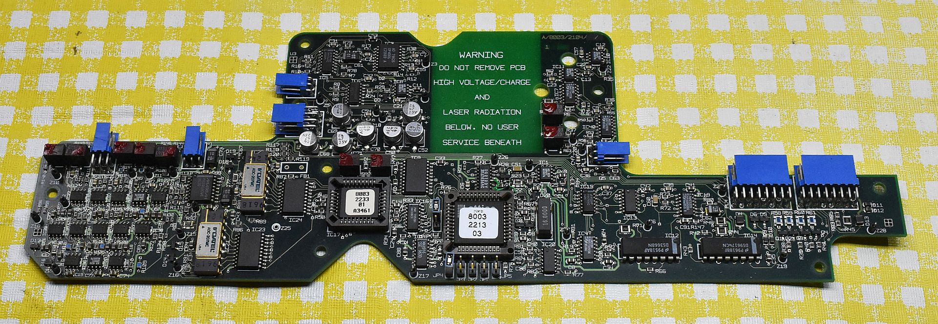
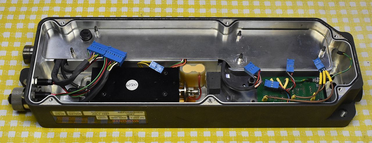
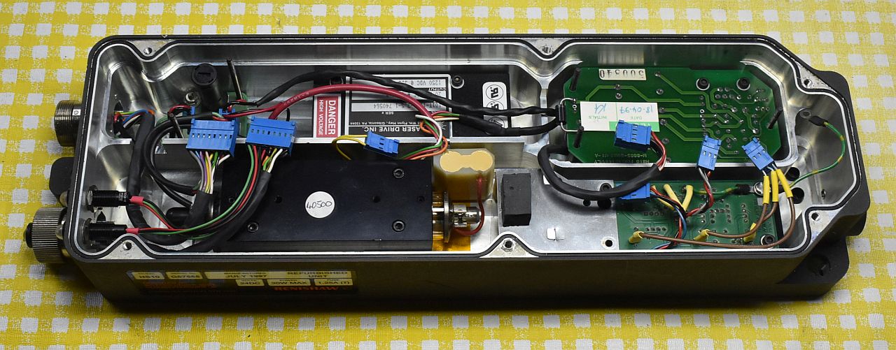
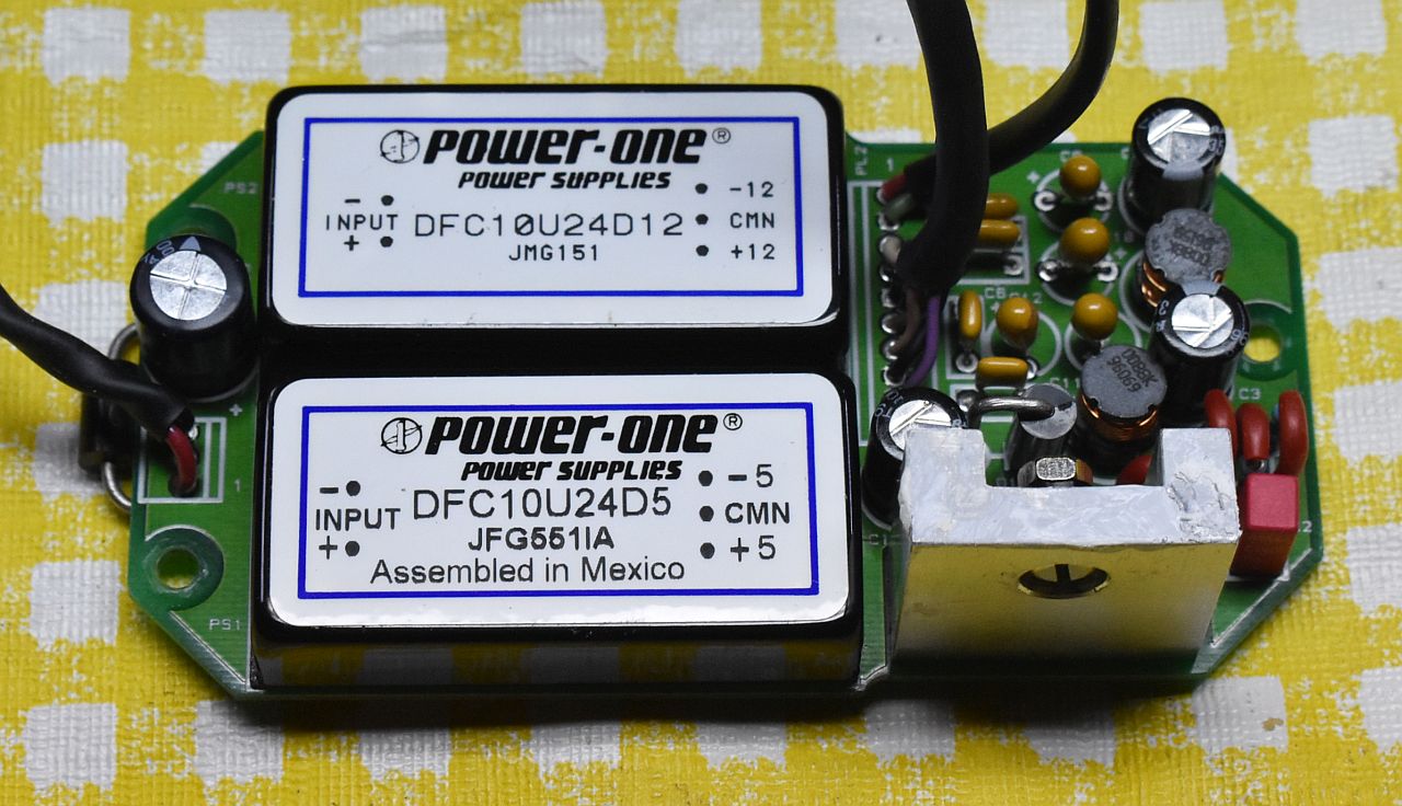
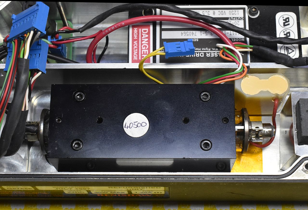
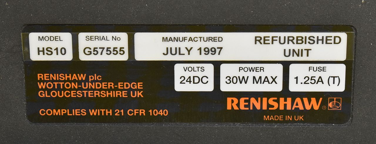
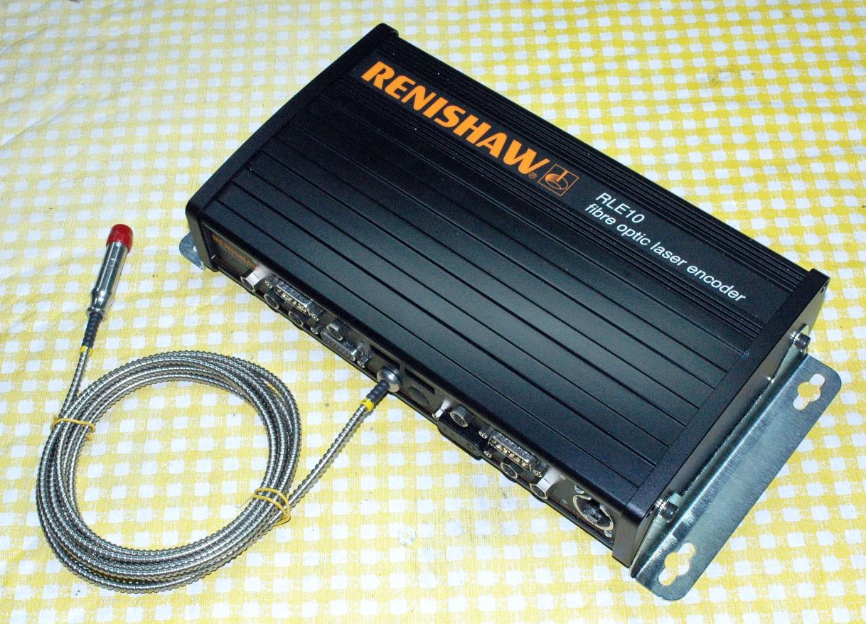
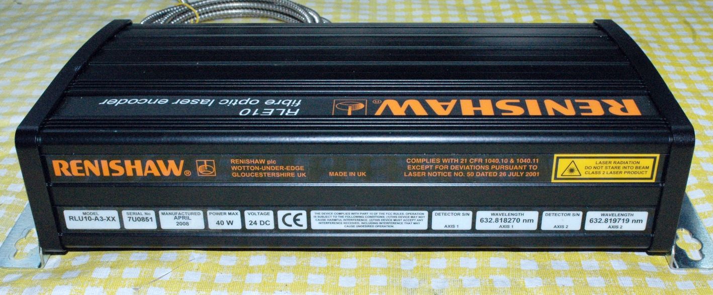
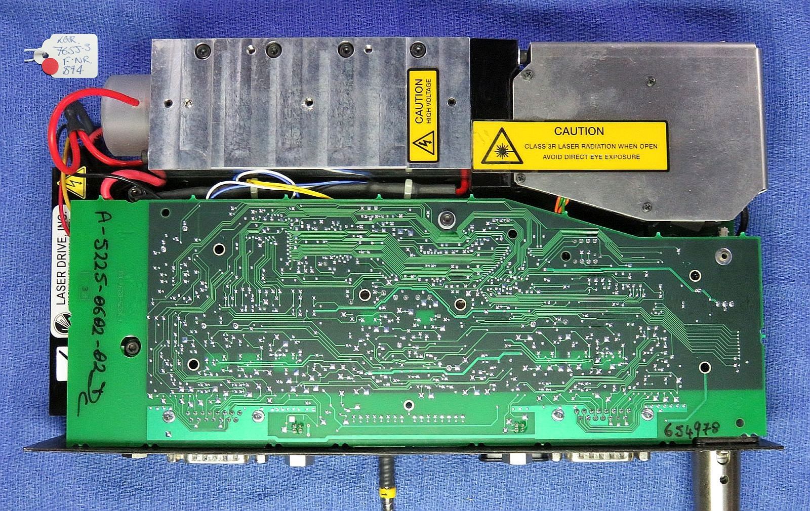
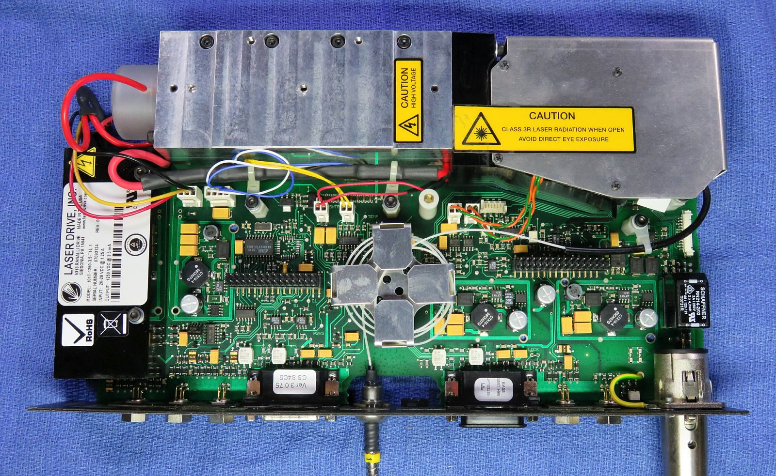
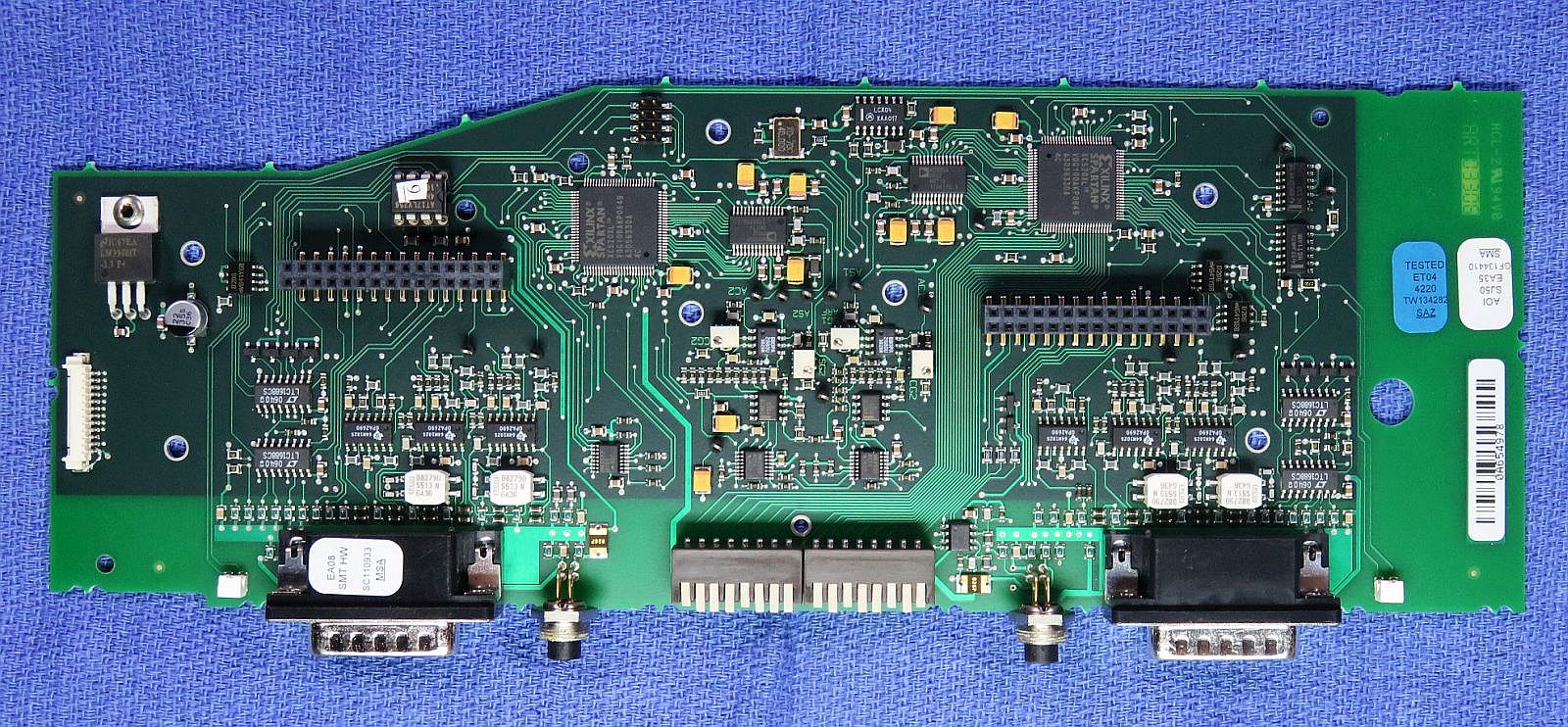
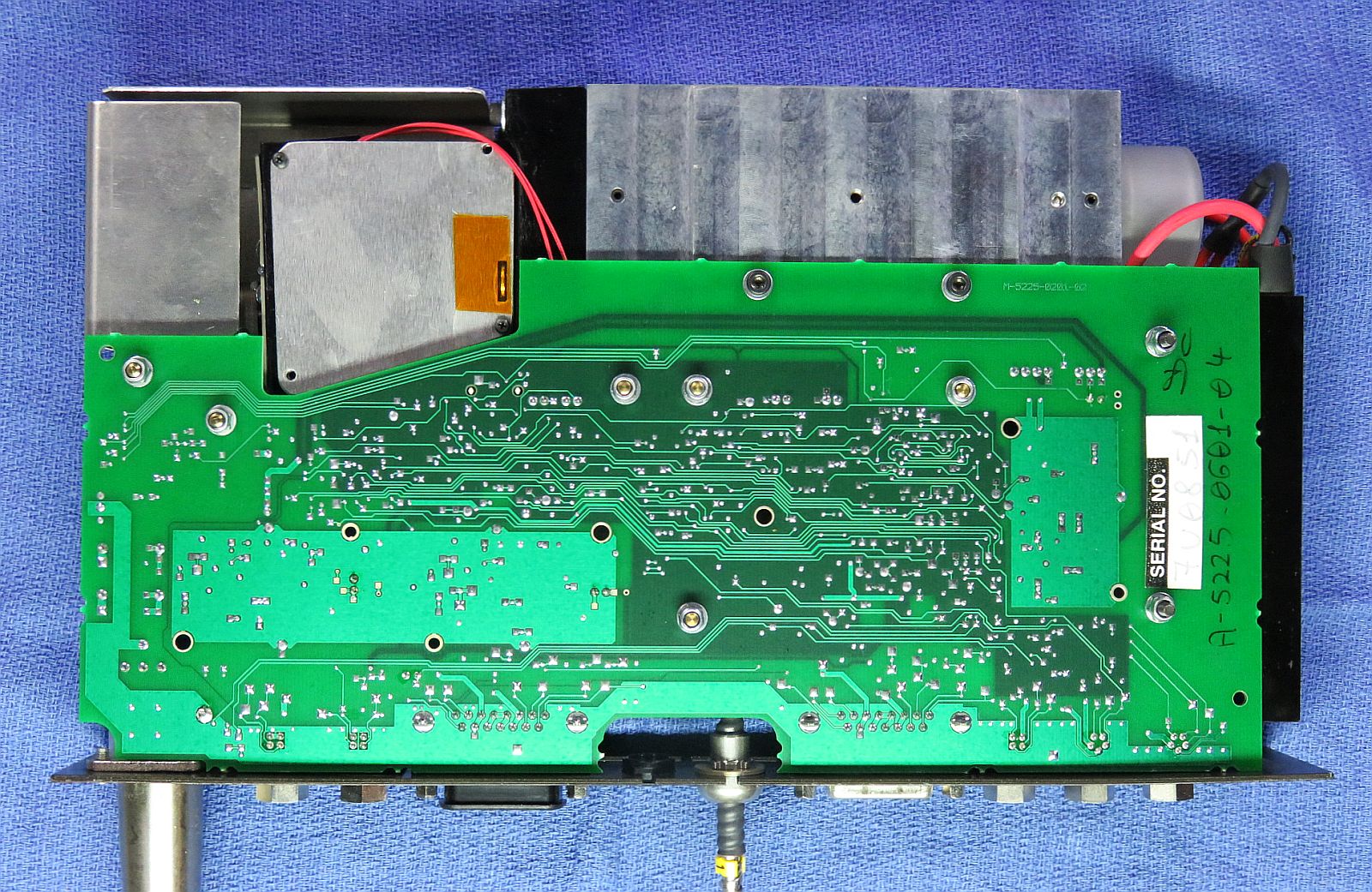
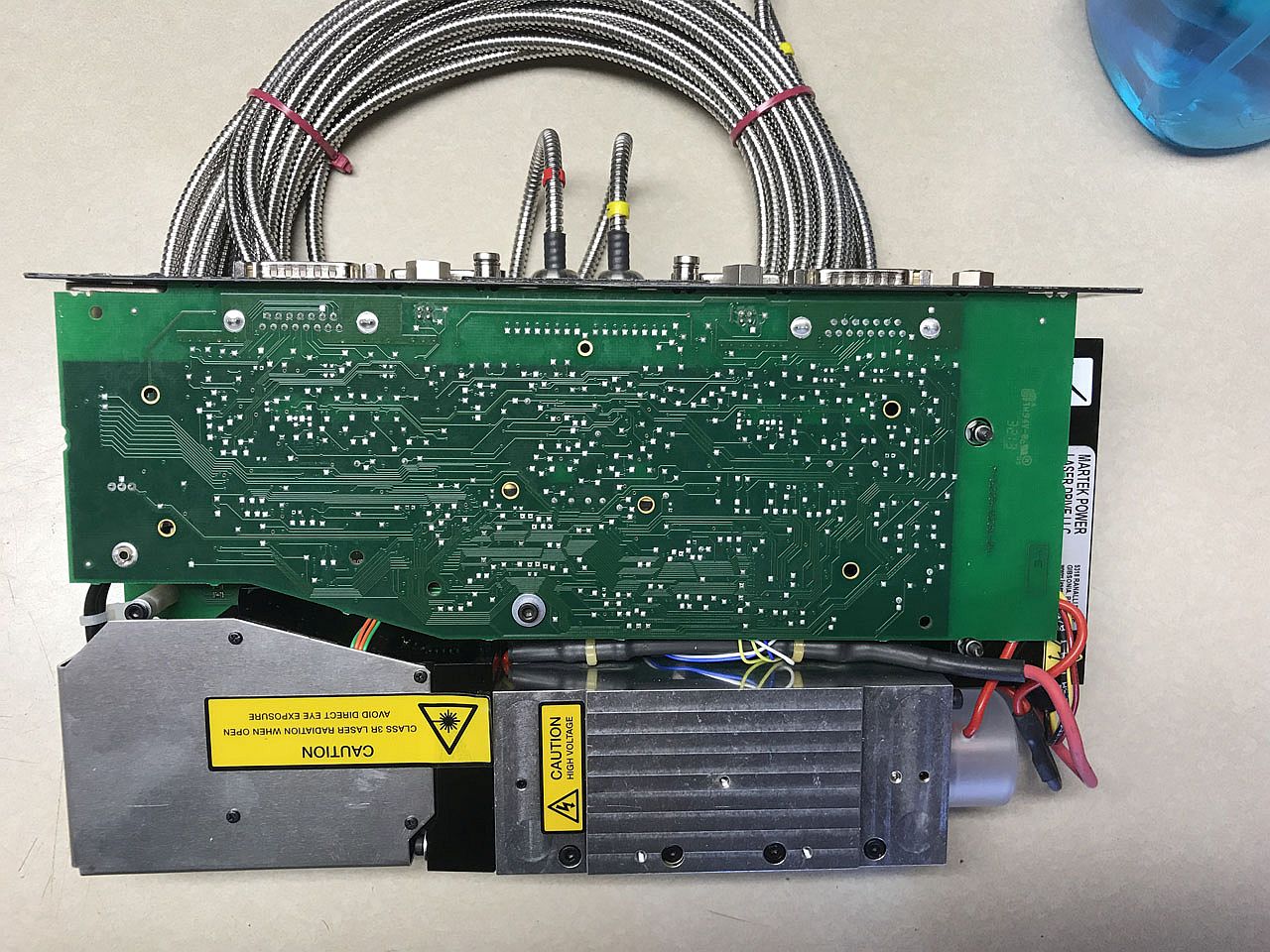
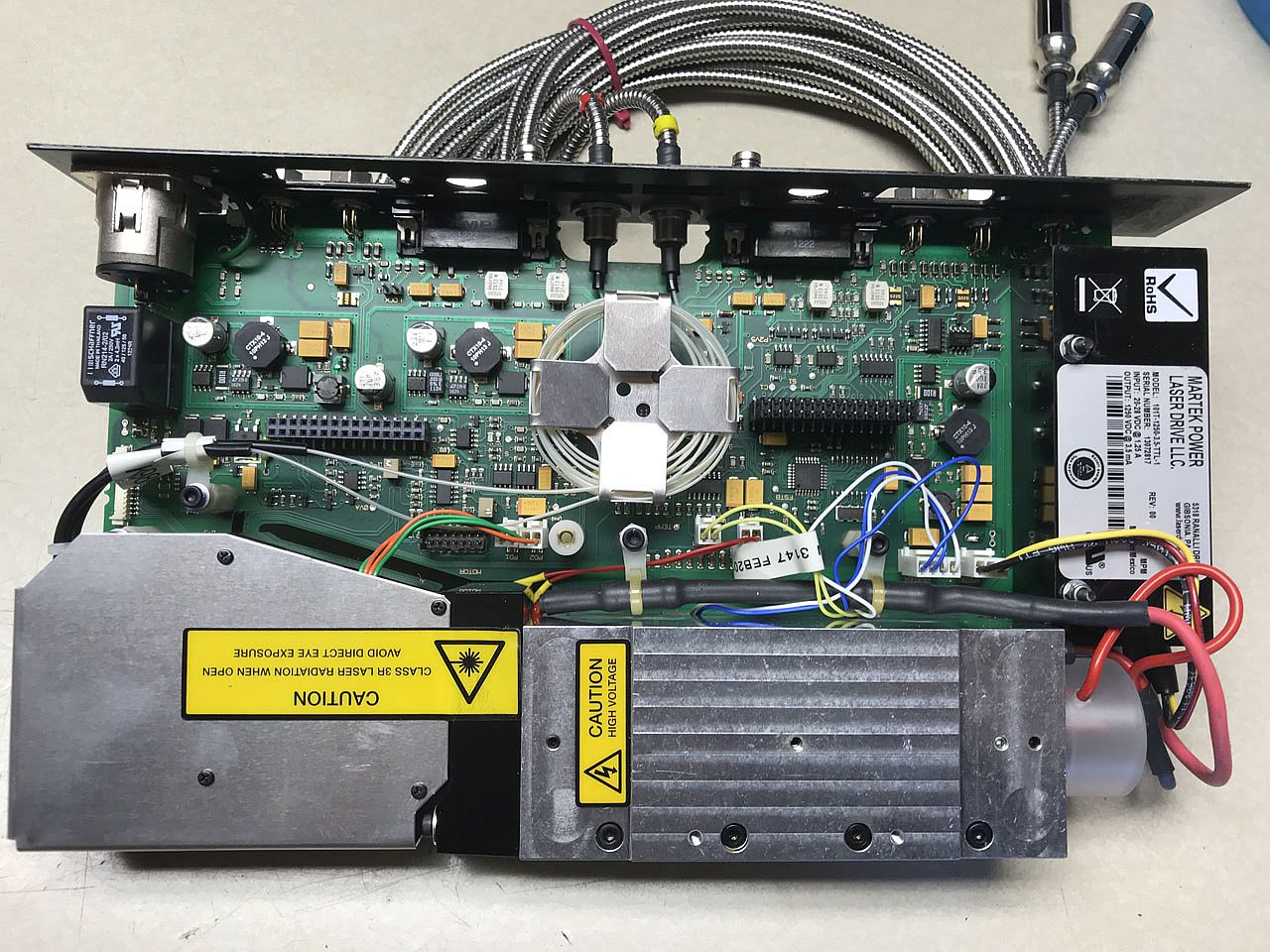
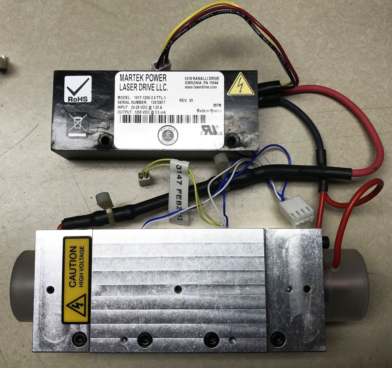
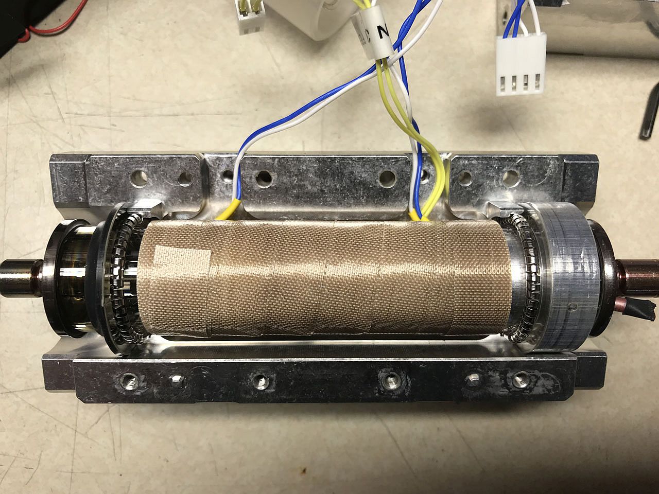
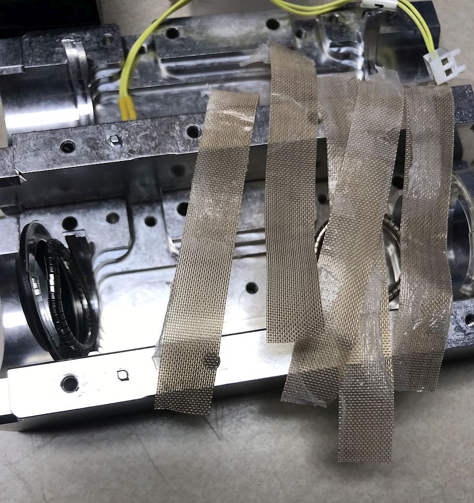
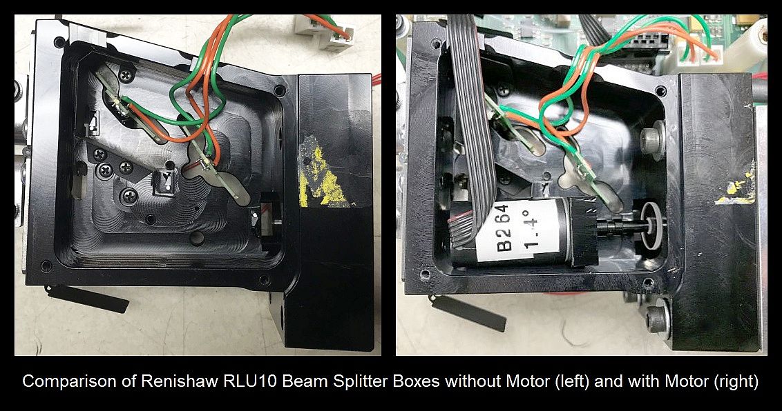
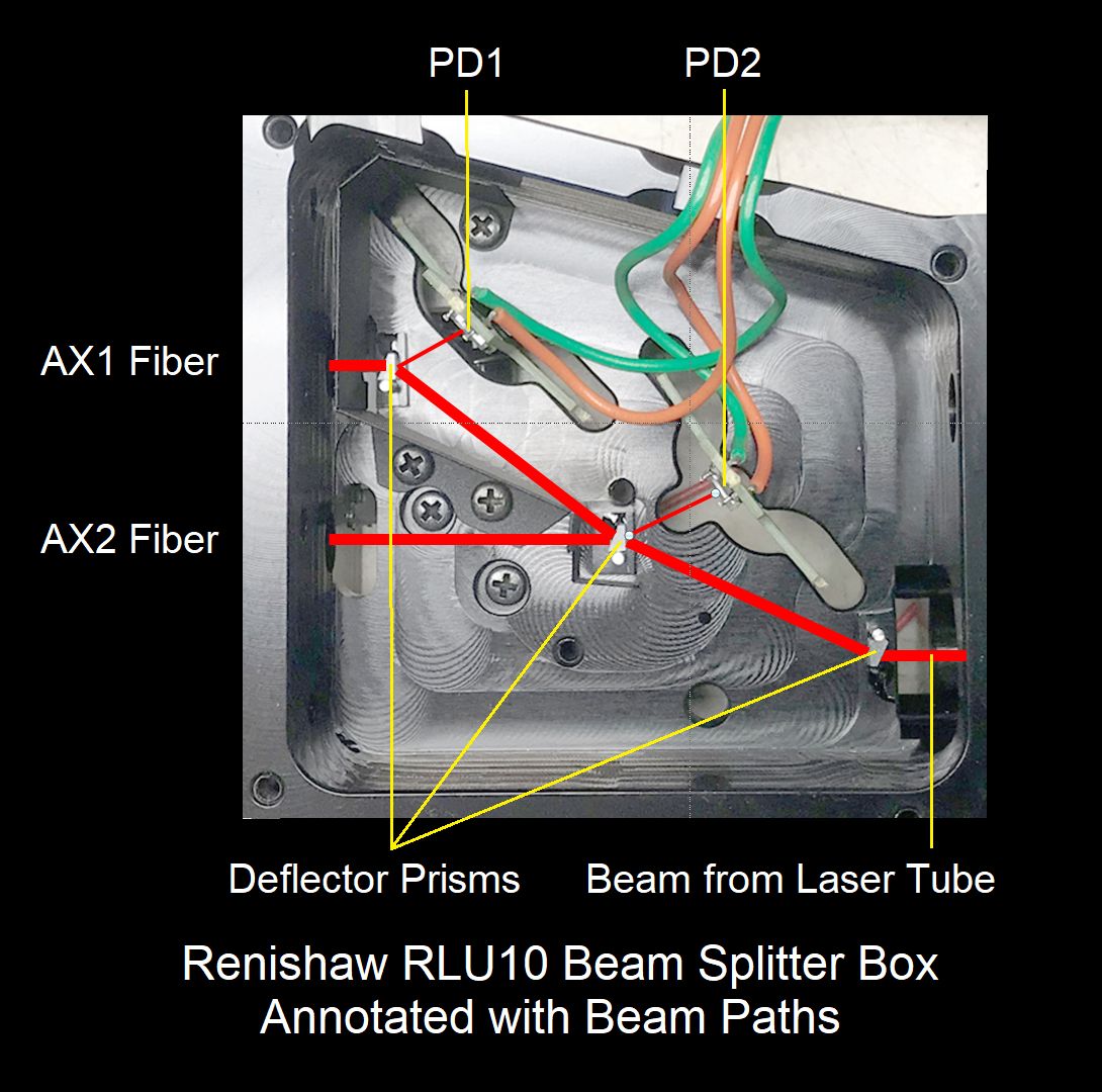
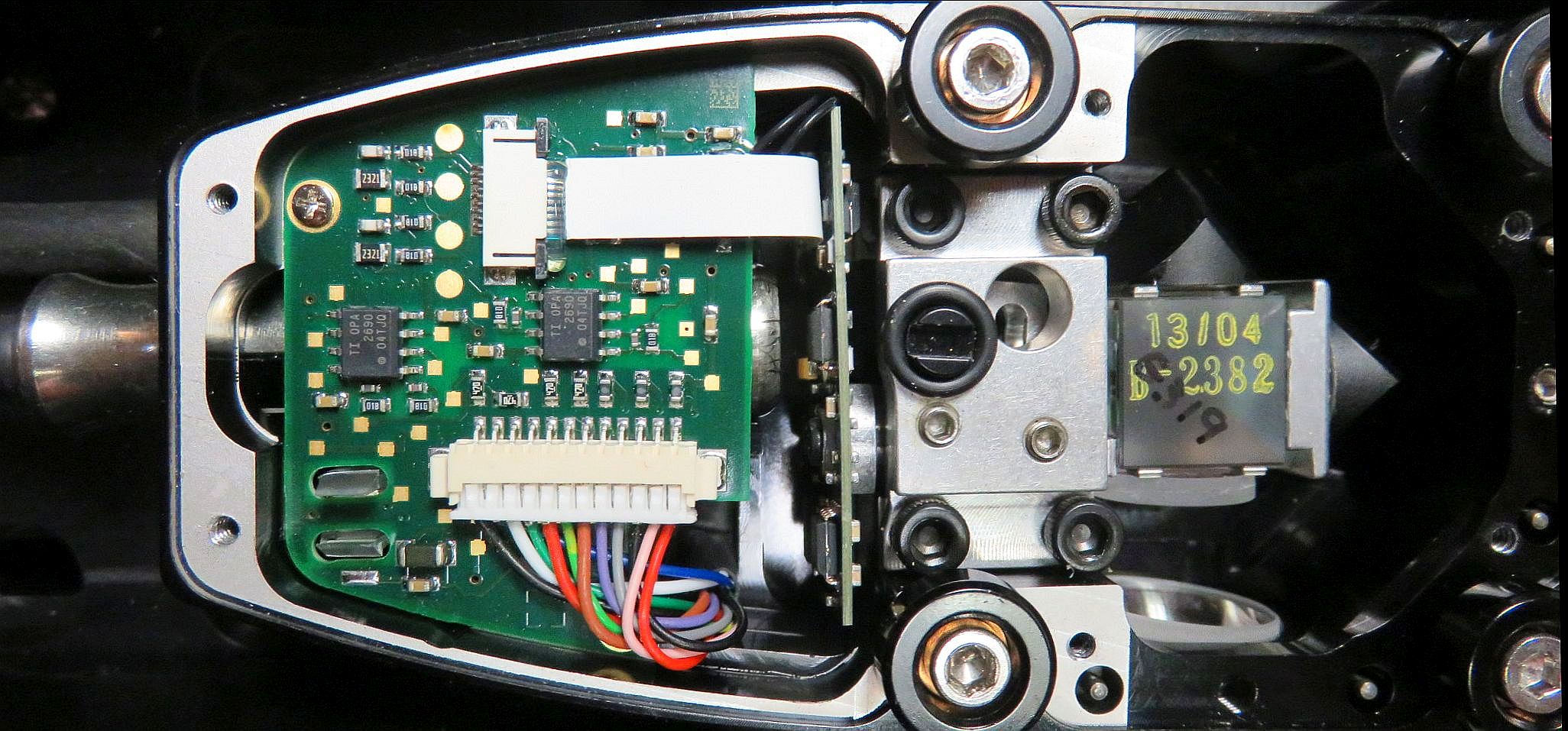
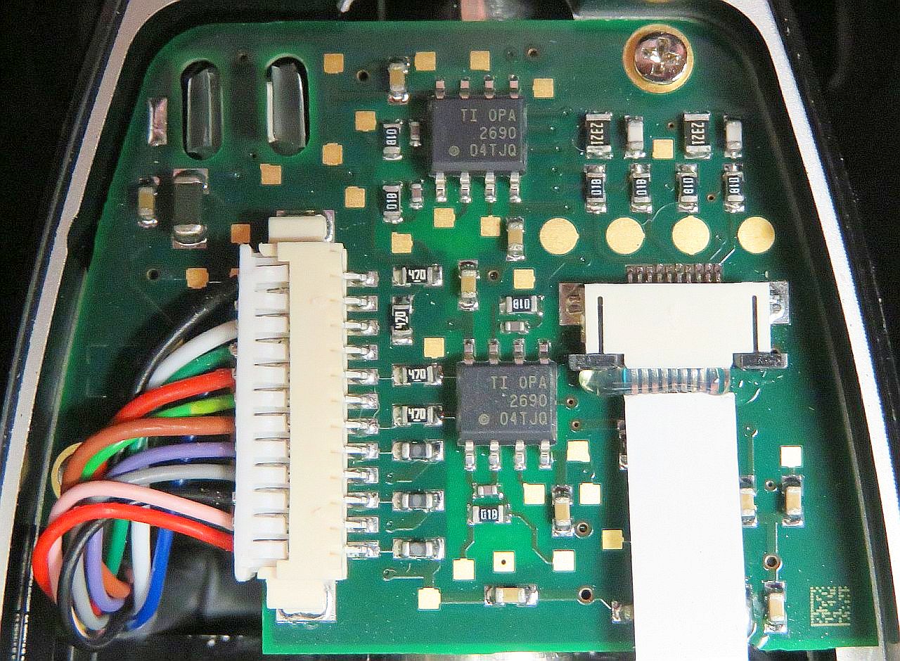
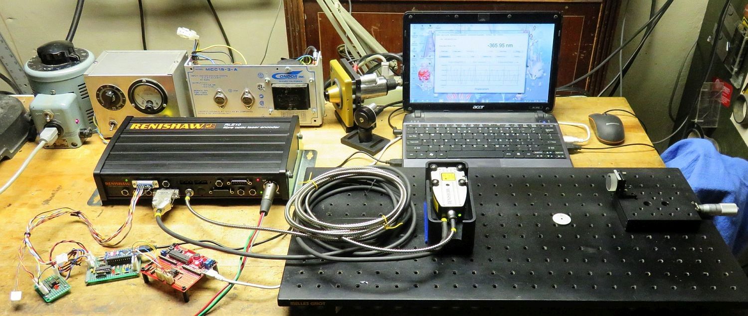
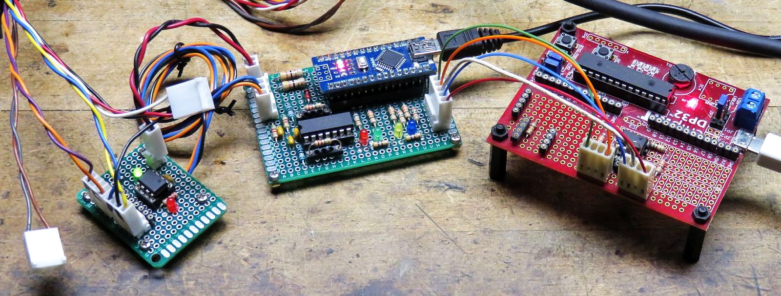
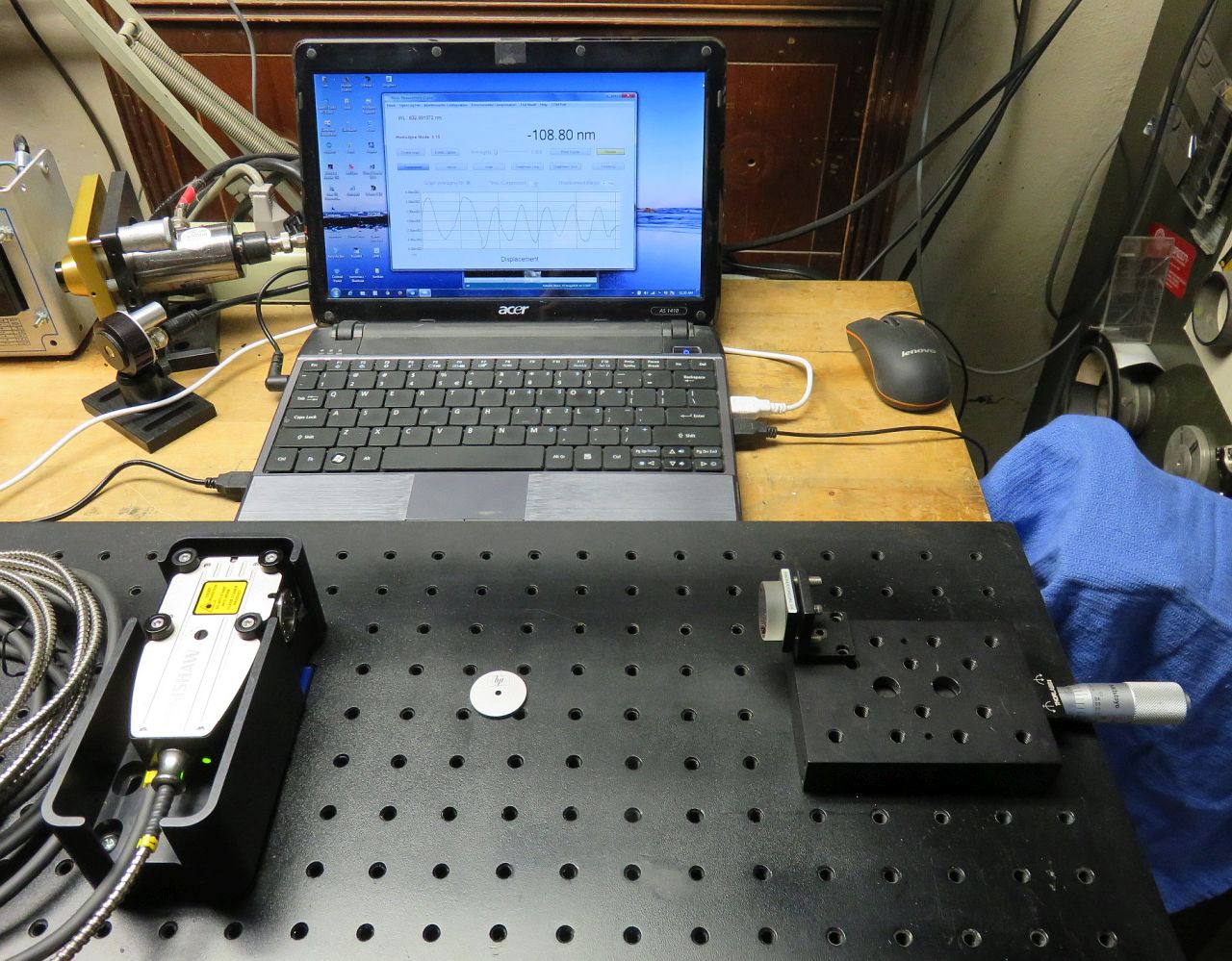
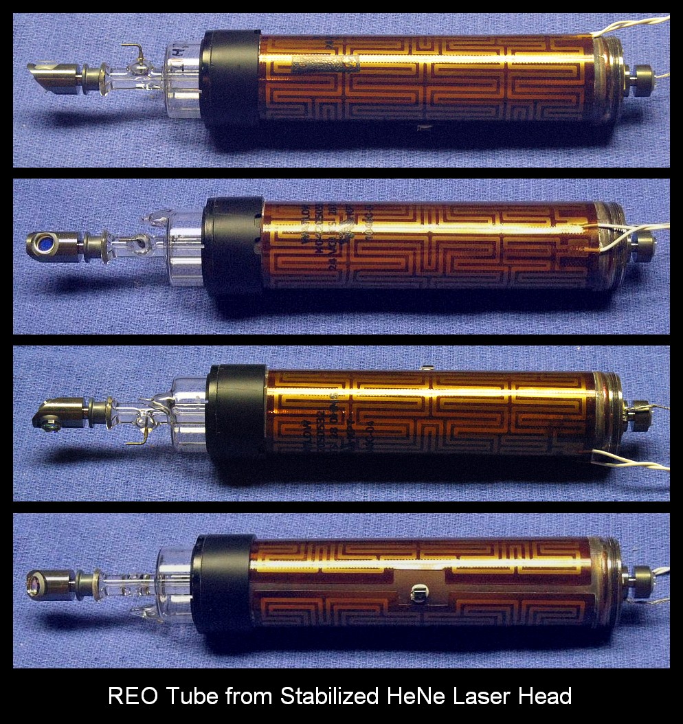
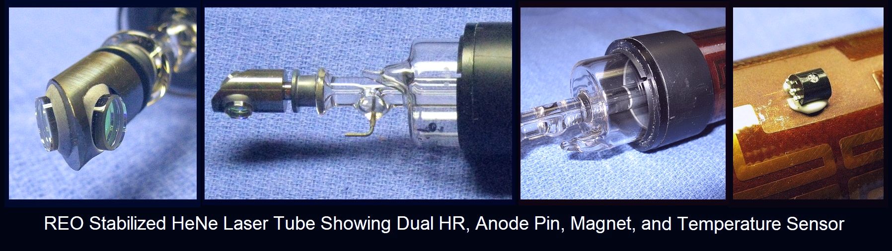
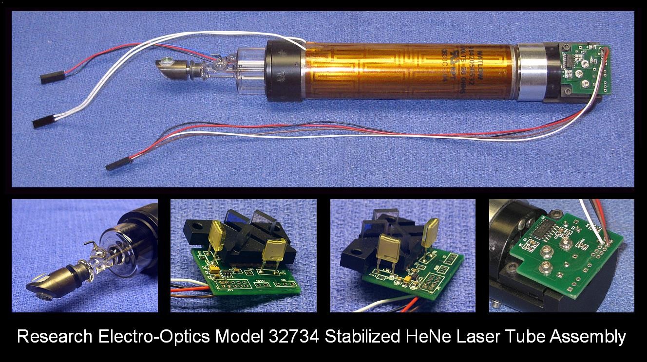
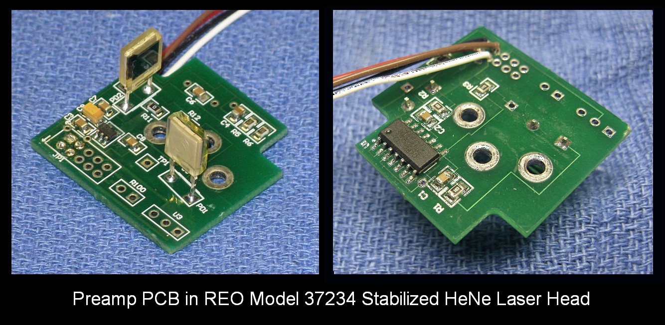
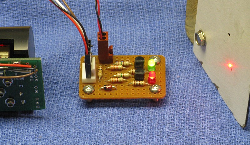
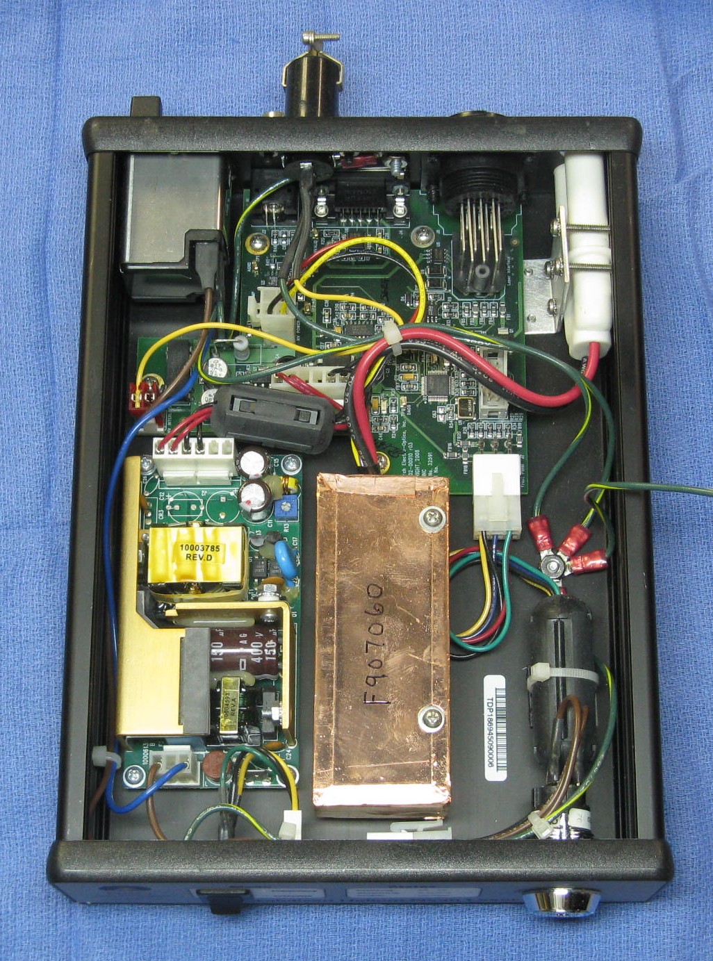
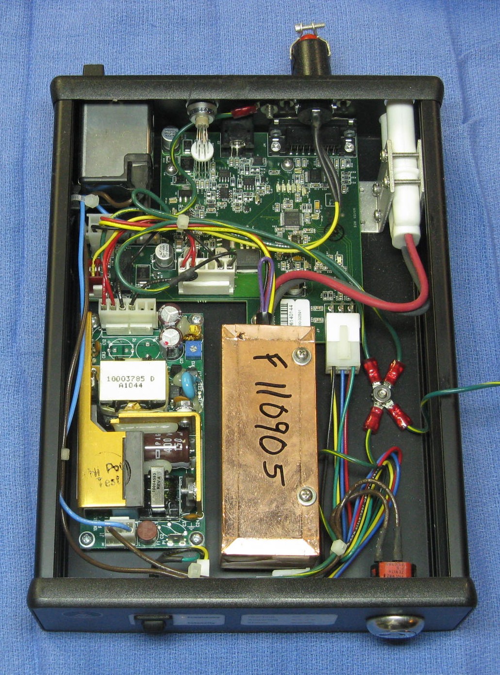
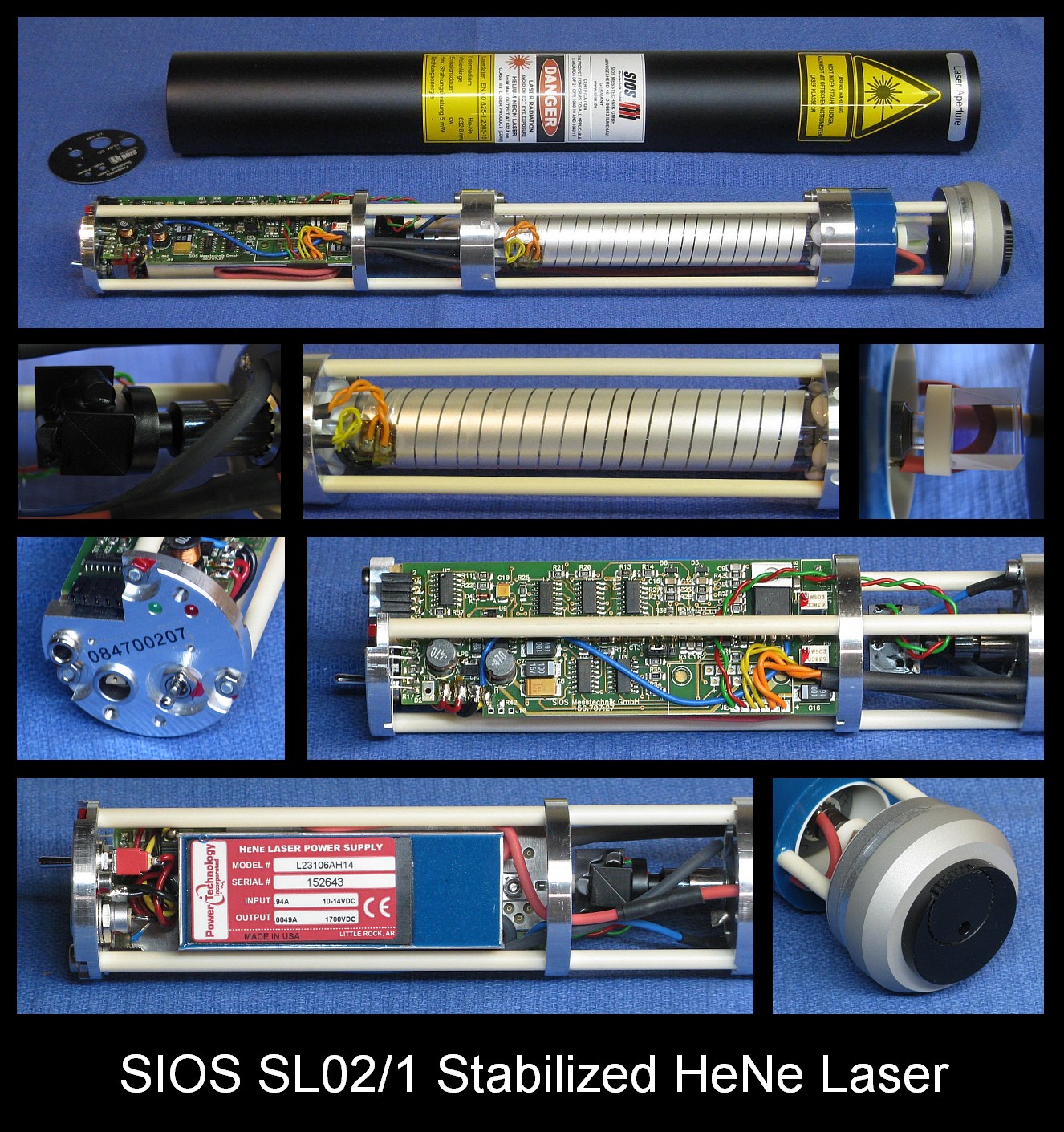
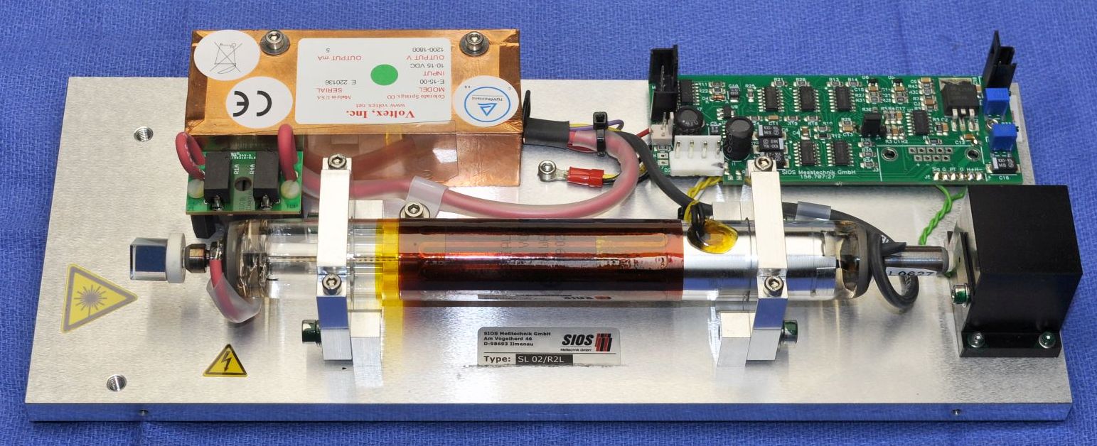
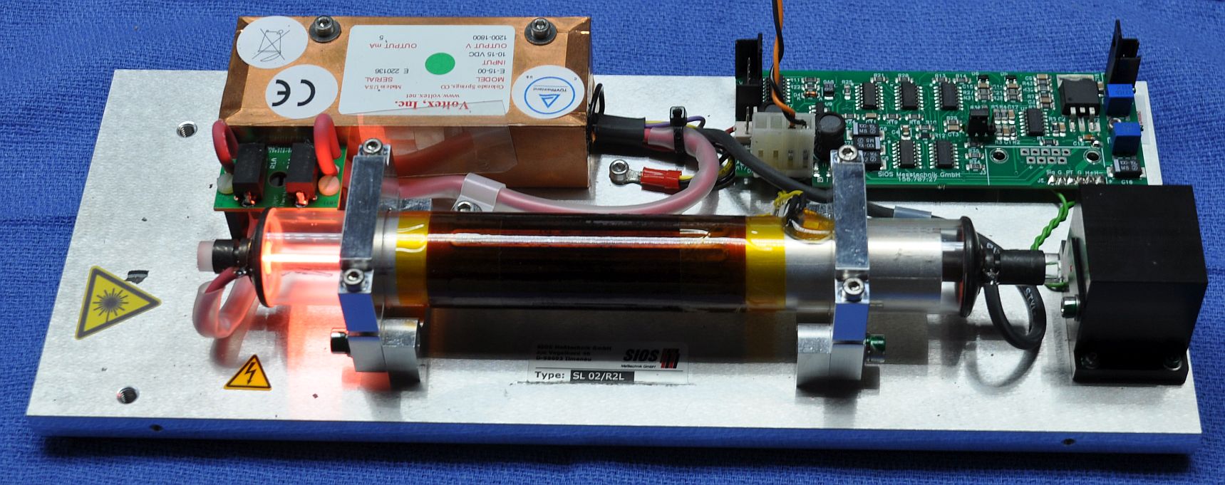
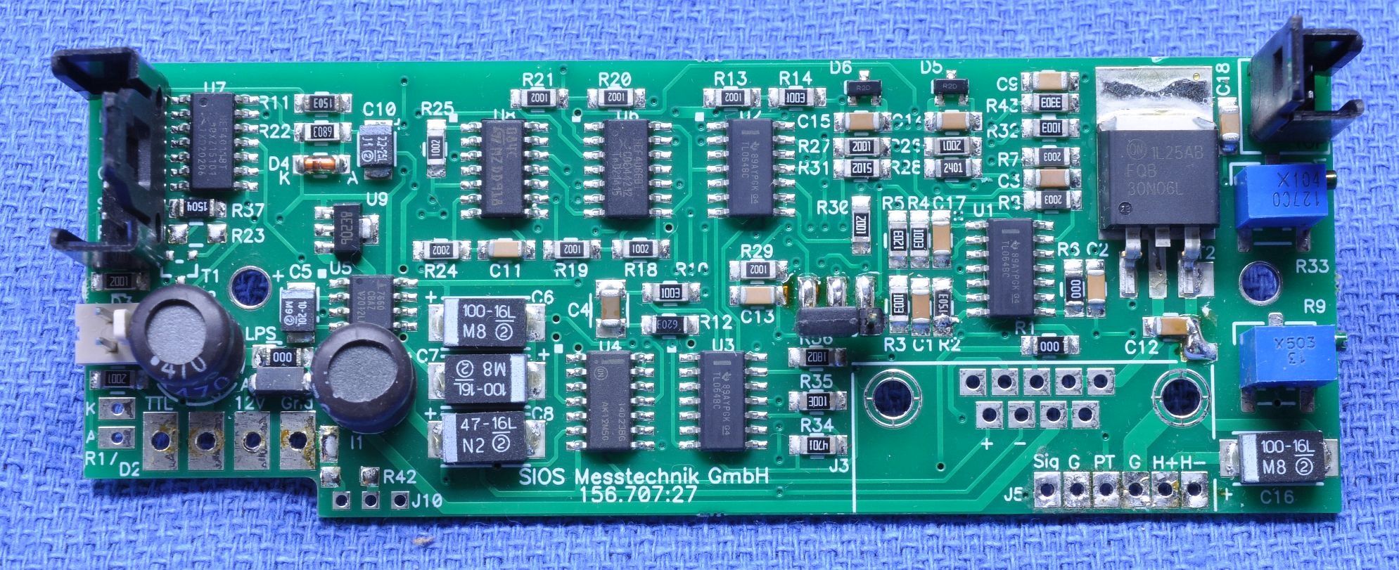
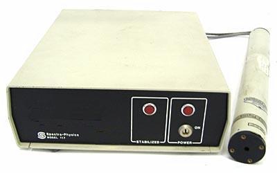
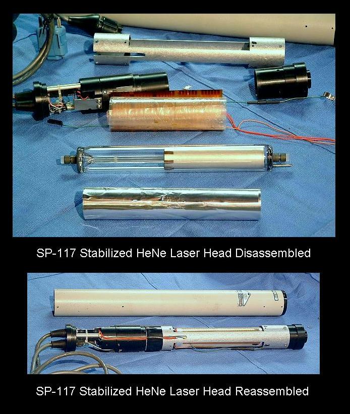
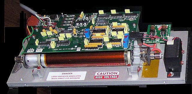
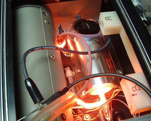
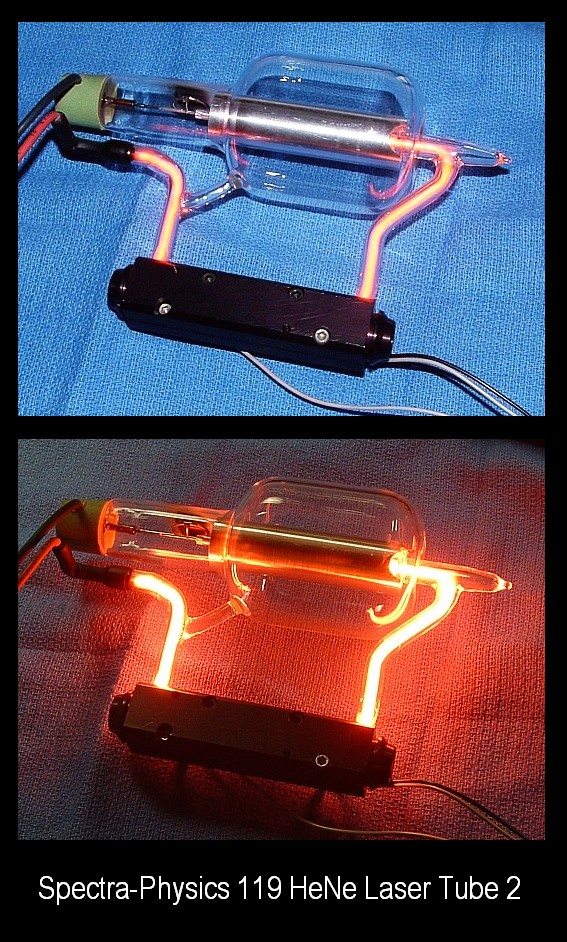
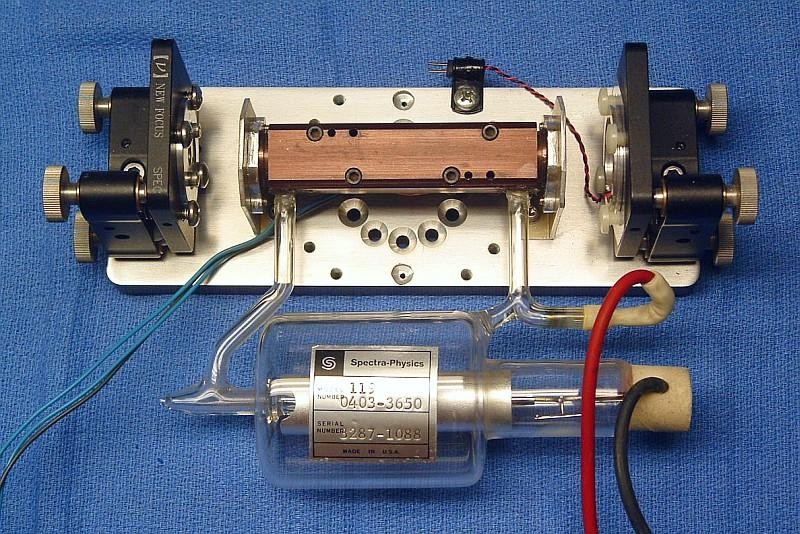
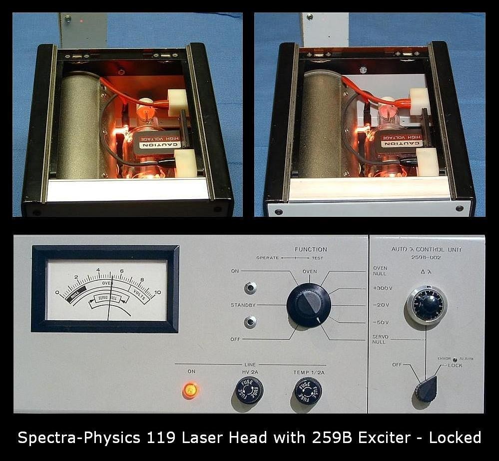
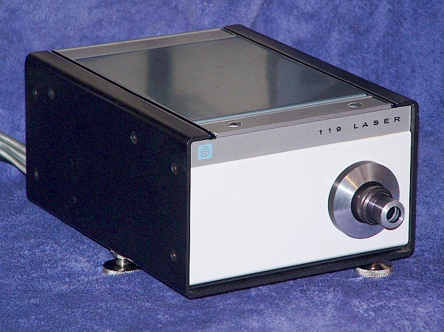
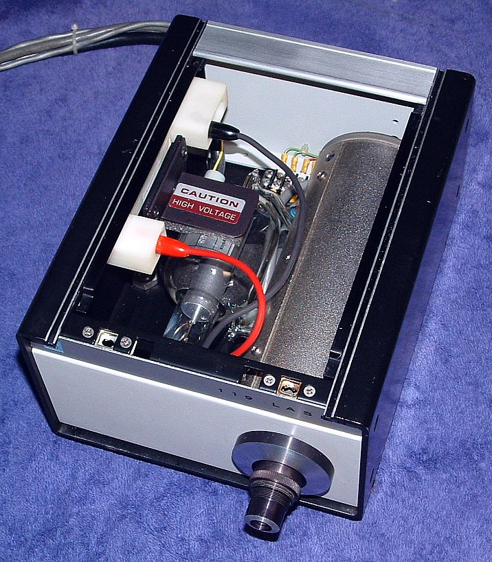
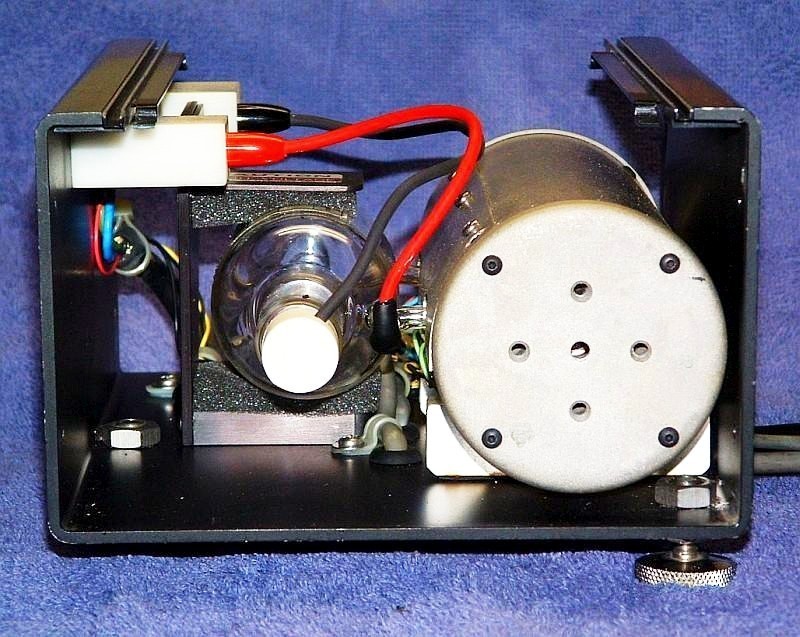
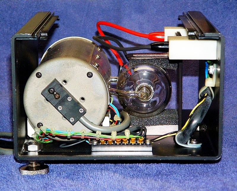
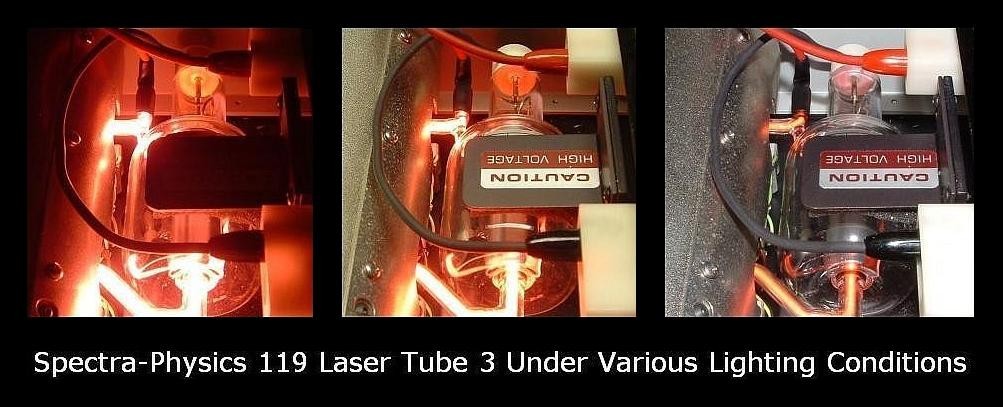
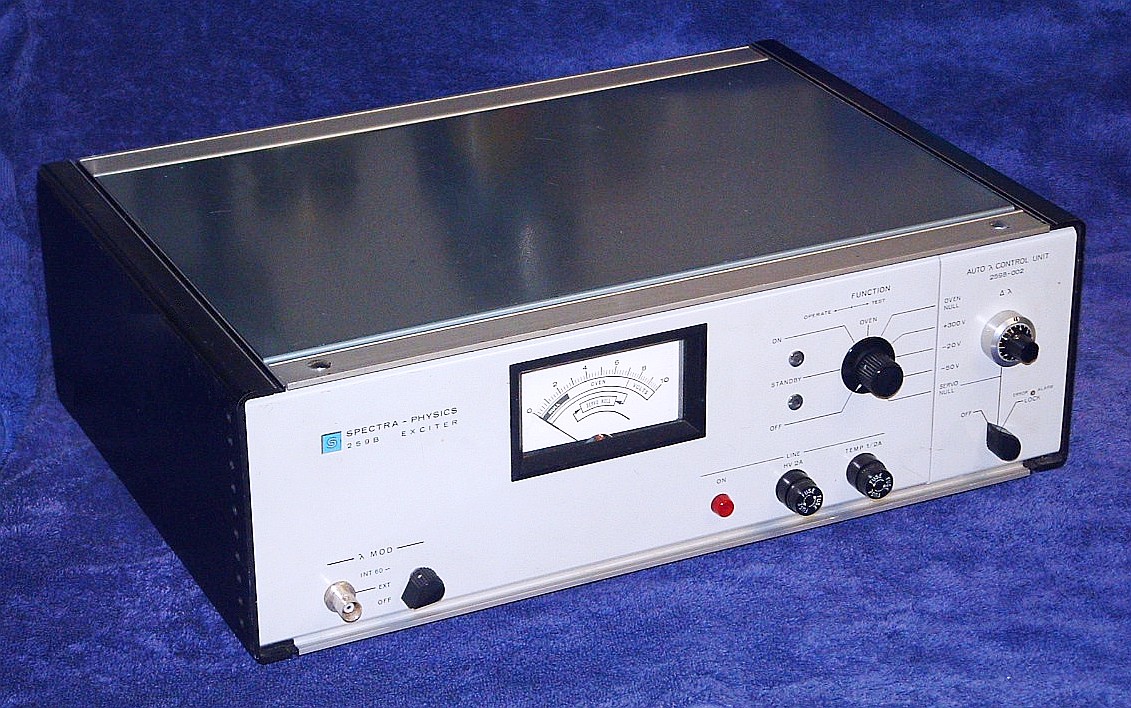
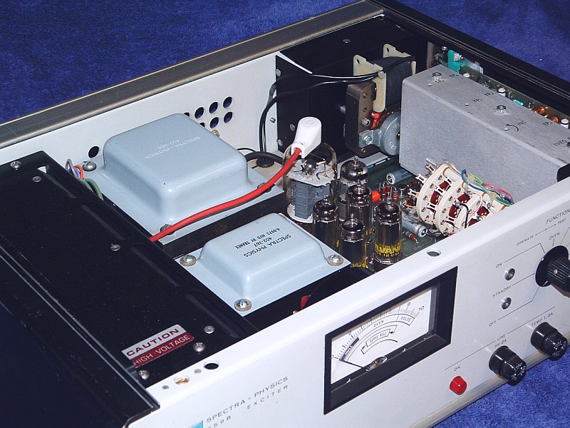
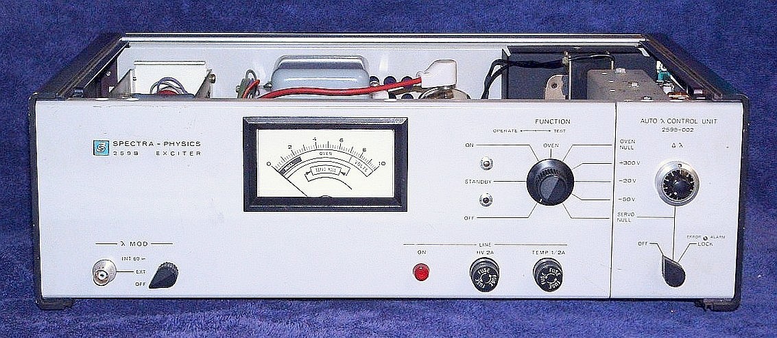
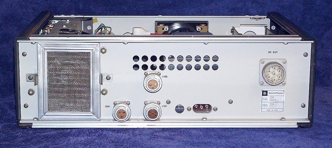
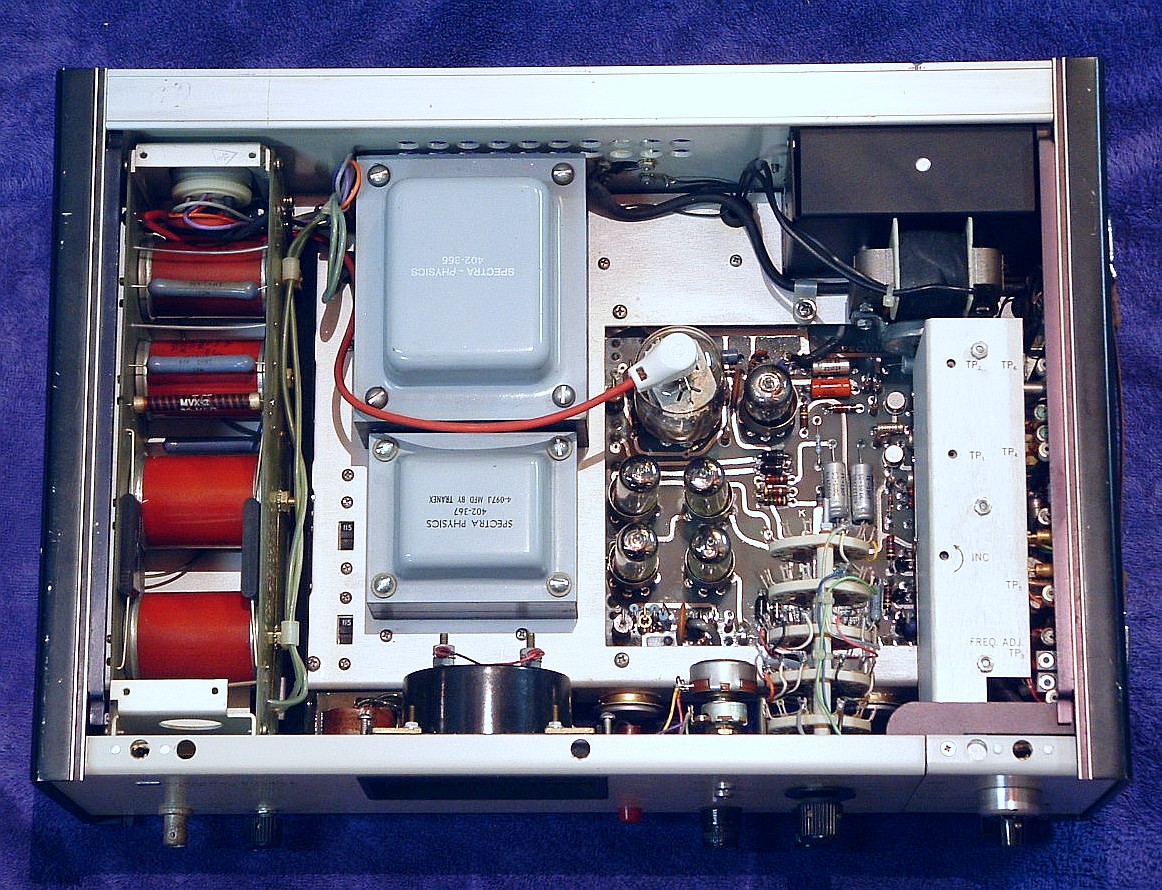
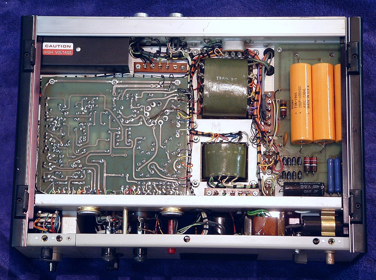
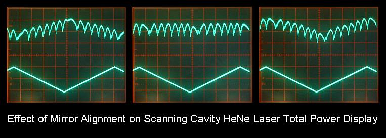
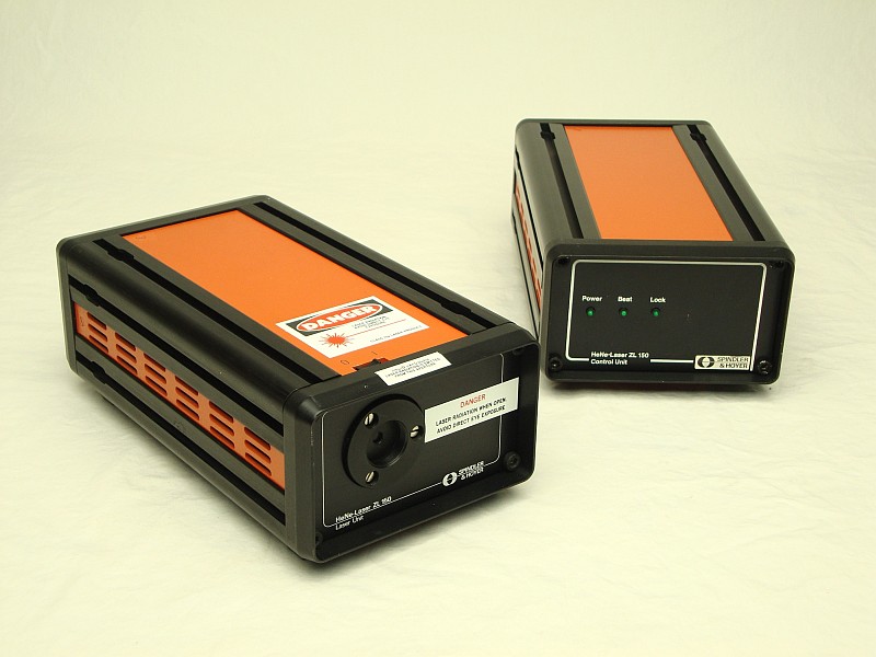
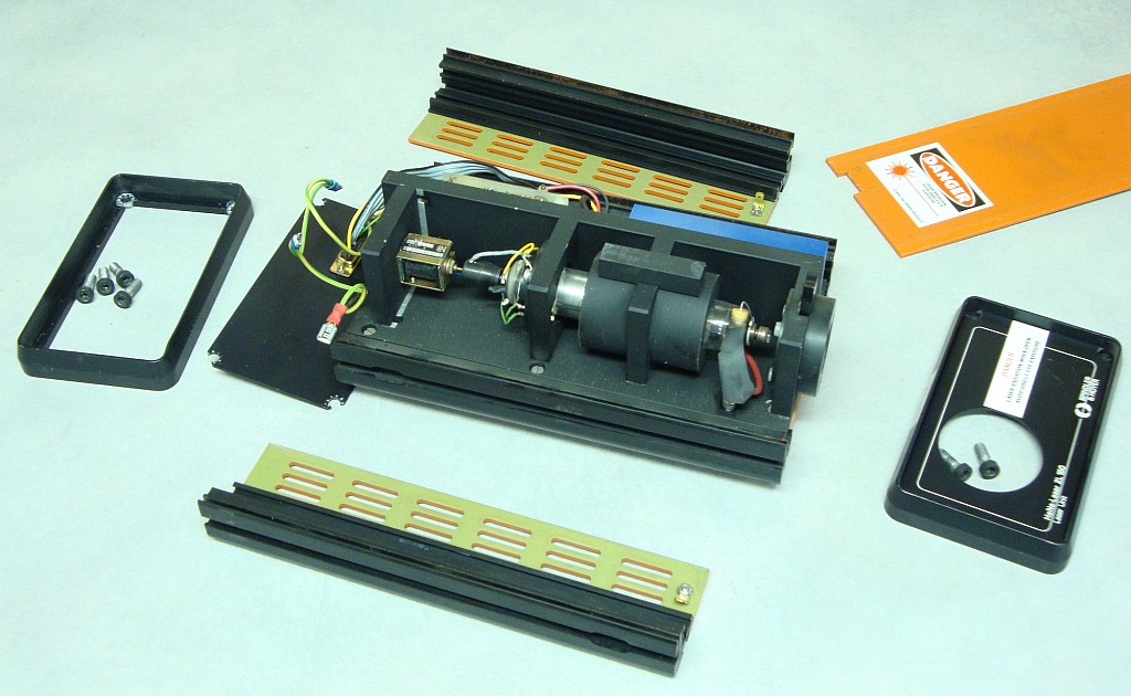
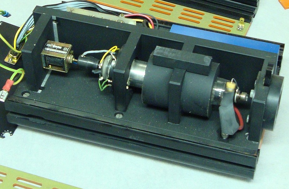
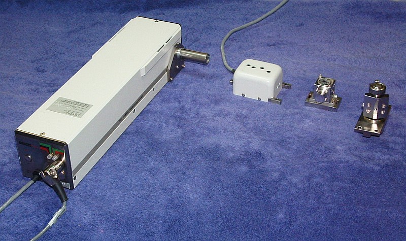
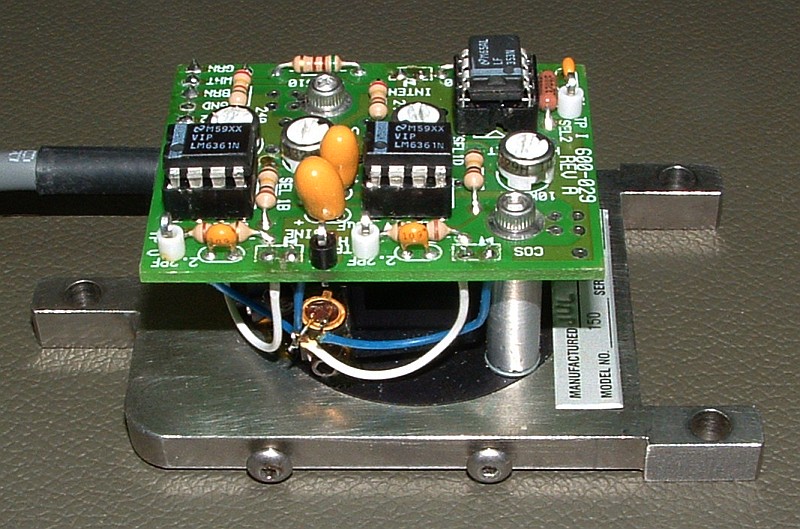
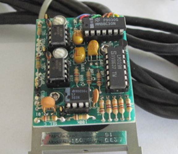
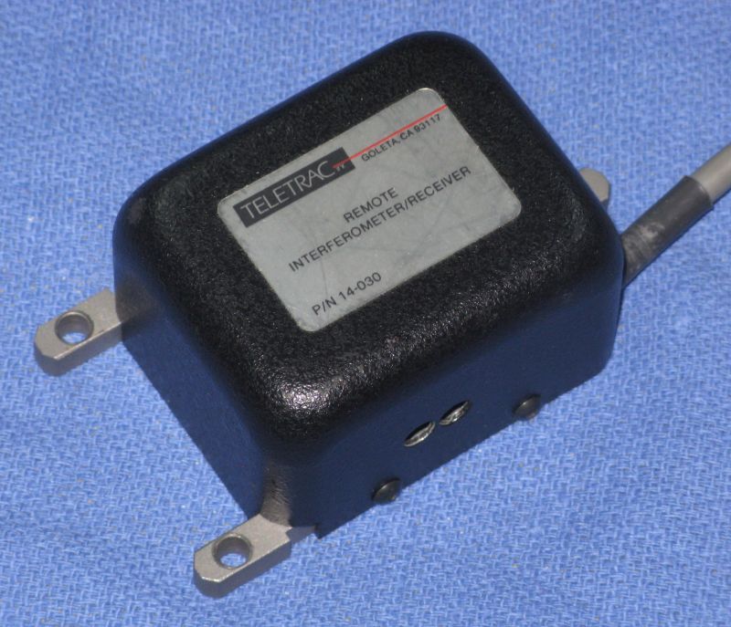
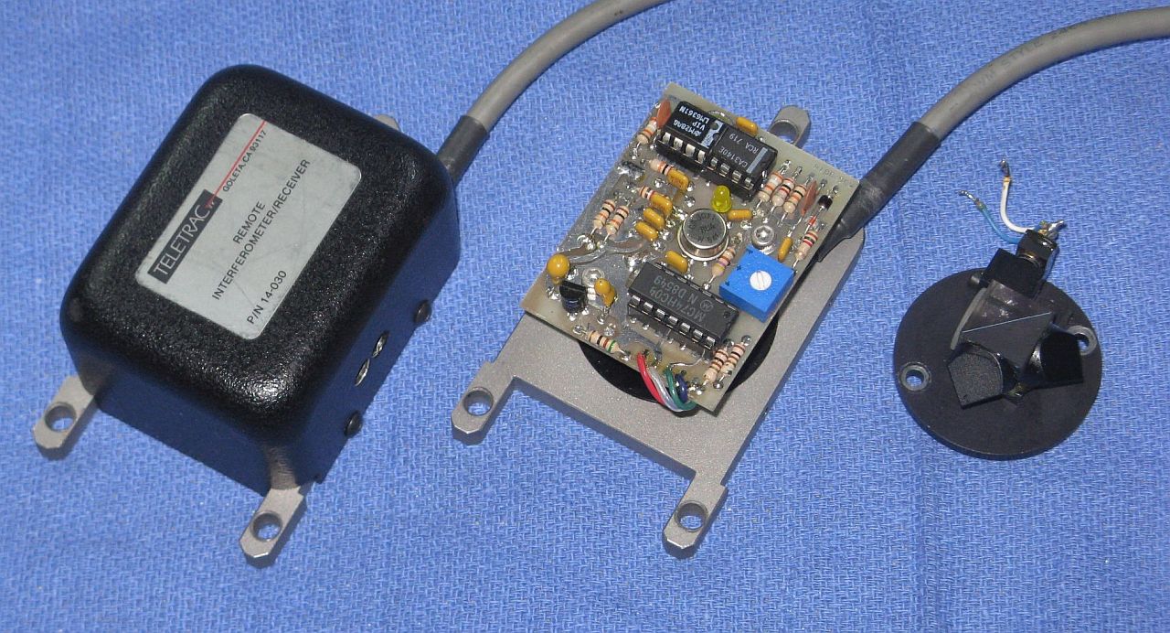
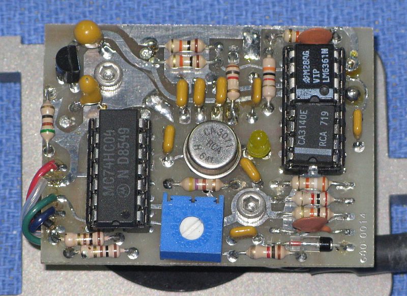
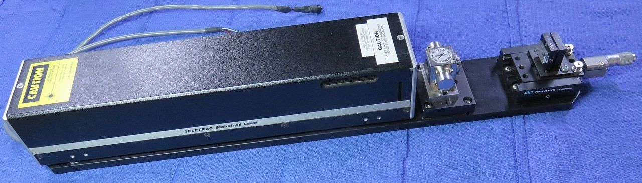
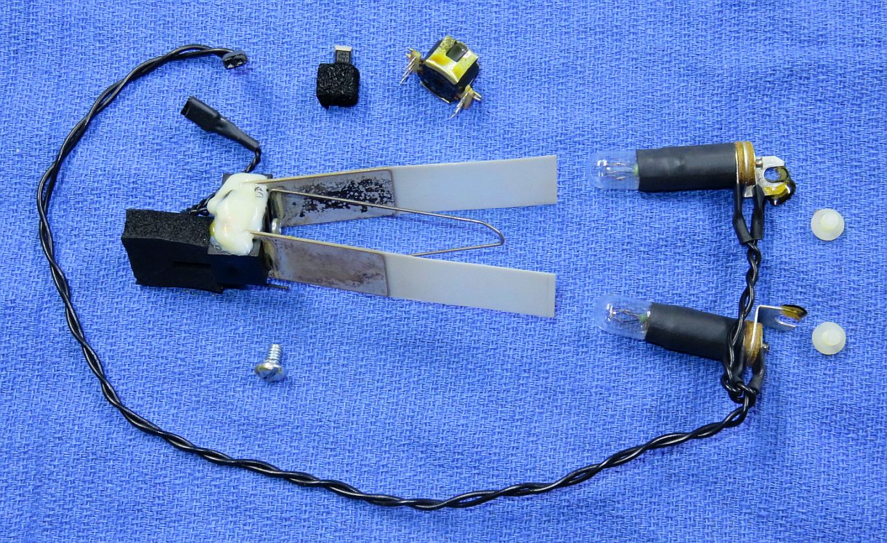
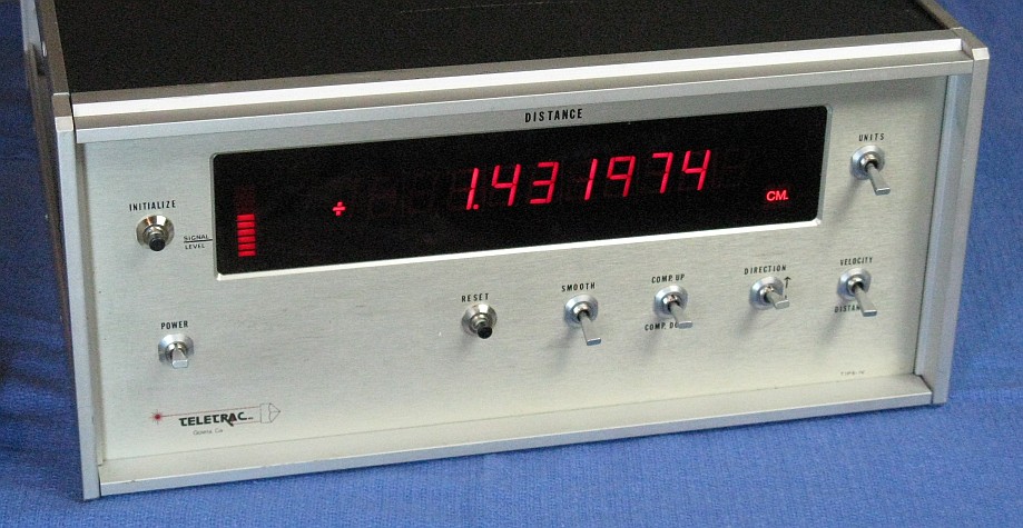
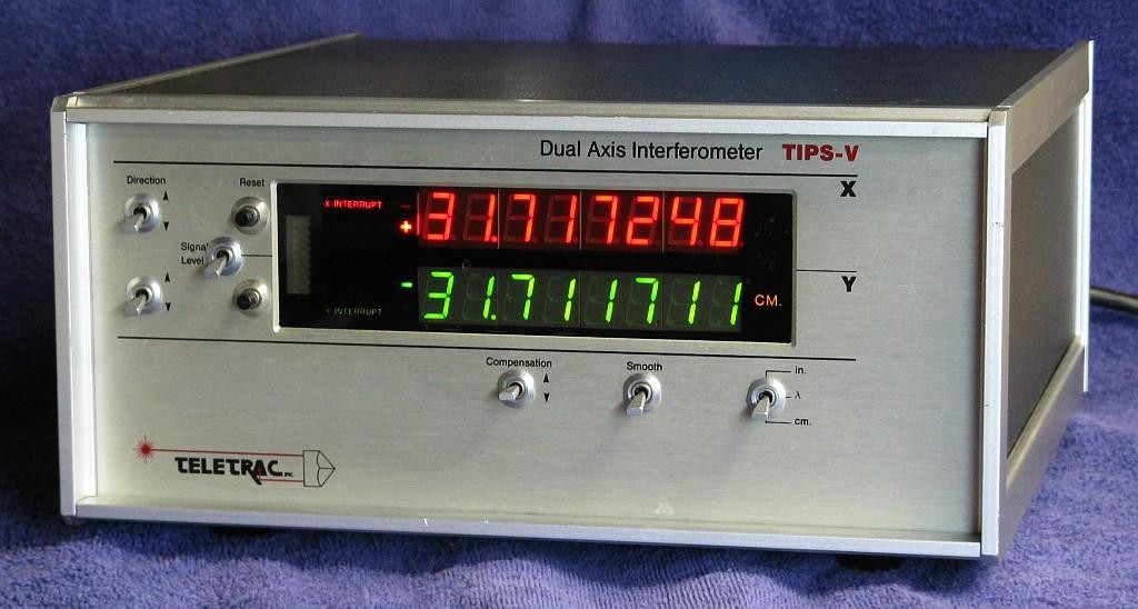
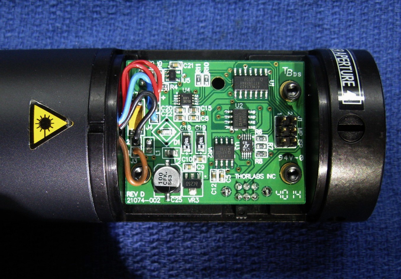
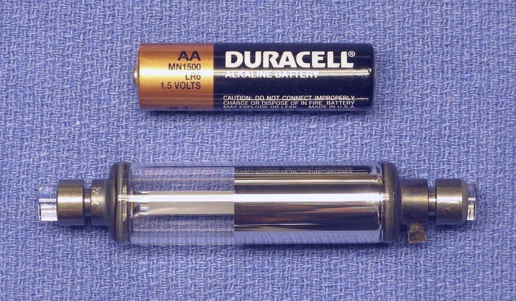
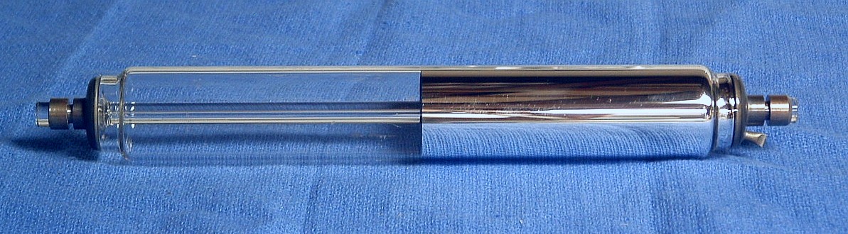
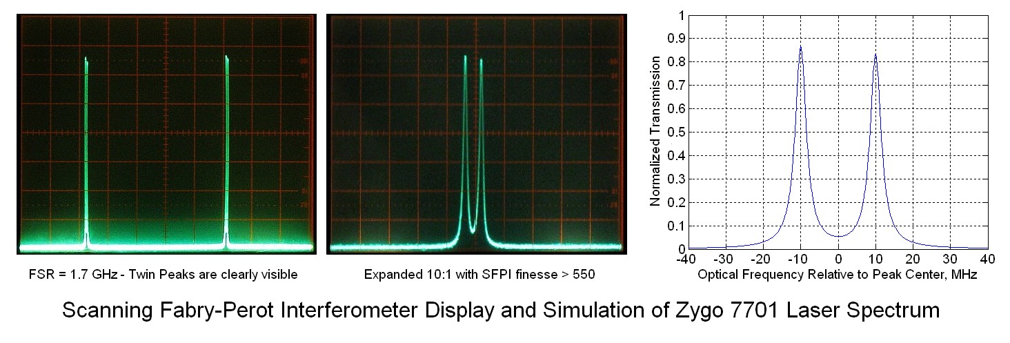
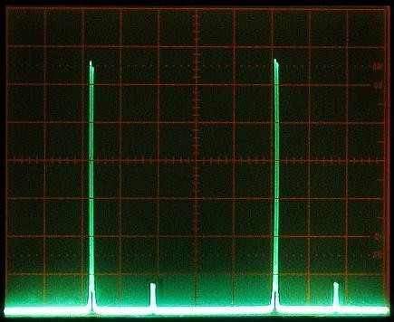
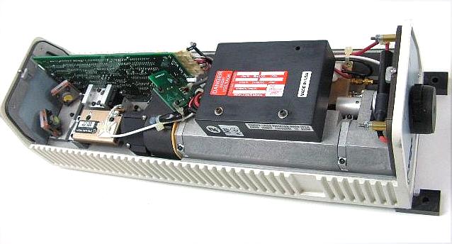
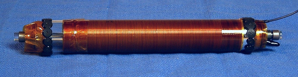
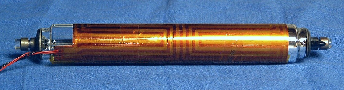
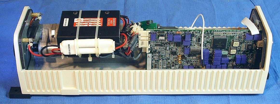
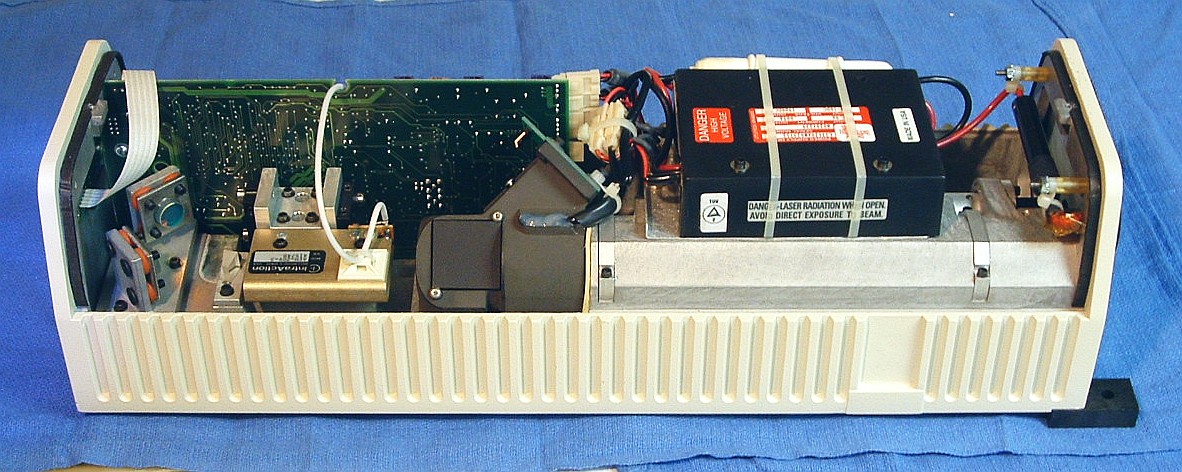
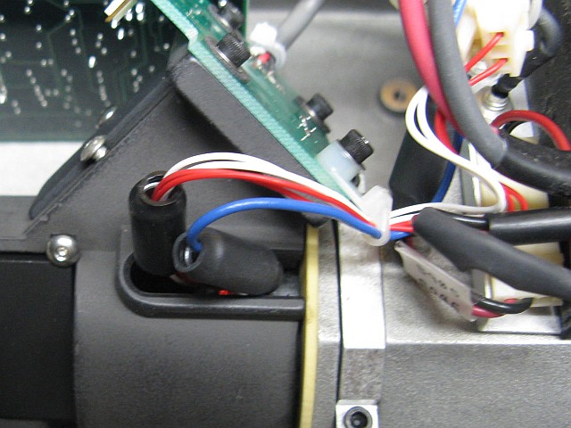
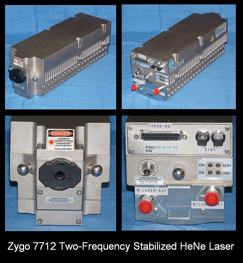
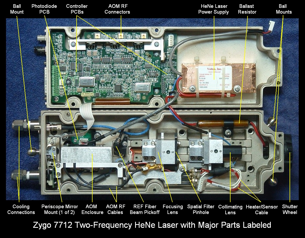
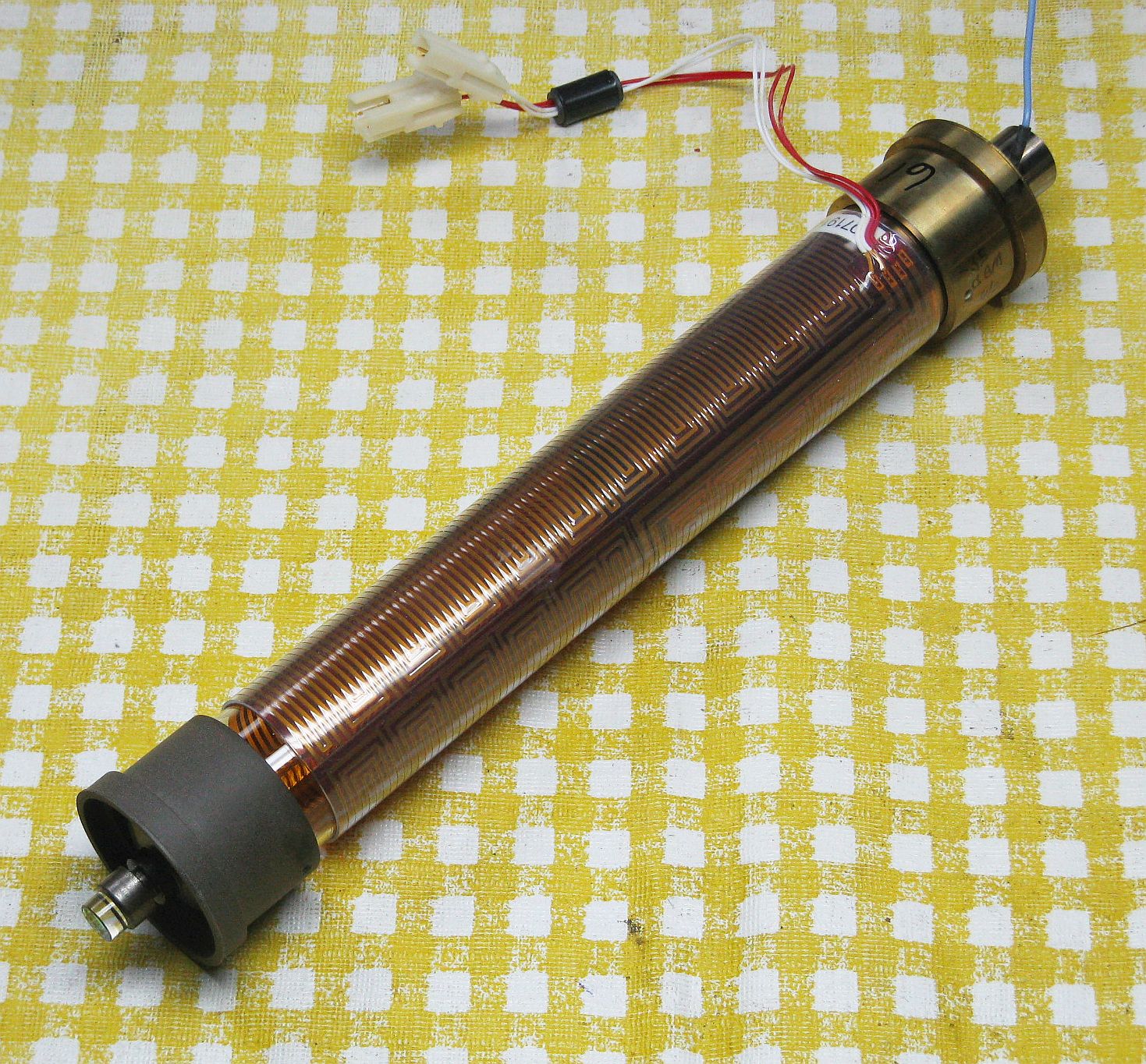
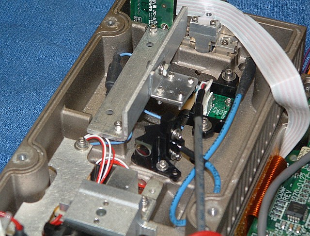
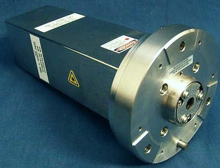
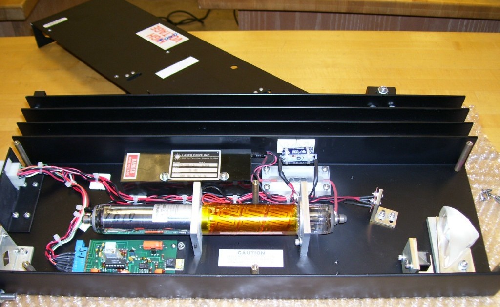