A few HeNe lasers - usually larger or research types - have used a radio frequency (RF) generator - essentially a radio transmitter to excite the discharge. This was the case with the original HeNe laser but is quite rare today given the design of internal mirror HeNe tubes and the relative simplicity of the required DC power supply as described later in this chapter.
Unlike laser diodes, the HeNe drive is not nearly as critical to performance and tube life. :-) Therefore, even if you do not have a datasheet for your tube, you can probably guess fairly closely as to its requirements and then optimize performance based on optical output alone.
Then again, see Oops! HeNe Laser Tube Meltdown. This is what happens if your tube and power supply aren't matched. Just kidding. I actually suspect that someone got just a bit carried away with a glass working torch to create this sculpture but it got your attention, huh? :) (This mantlepiece sculpture was created by Wayne Crowther (esoteric@pacifier.com).)
With these, at most you will have to add a ballast resistor and power line or battery connections. Models are available that run off either low voltage DC (regulated is desirable) or 115 or 230 VAC.
See the section: Examples of the Use of Commercial Power Supply Bricks.
See the section: Laser Safety with respect to the optical hazards associated with lasers. While not in the metal cutting class, careless use of higher power HeNe lasers, especially, can result in permanent damage to vision. Many are only Class II or Class IIIa but some are well into the Class IIIb range.
HeNe laser power supplies utilize high voltage at low current. The few mA needed to operate the HeNe tube or even a 10 kV starting pulse tube can certainly give you an unpleasant shock but will not likely be enough to do lasting damage. However, there may be much more current actually available and there is always the possibility of collateral damage:
Always discharge between the power supply output and/or HeNe tube terminals, and between each of these and the earth Ground or common of the power supply and case of the laser head (if not tied to the cathode) before touching anything inside or even the esposed ends of the head's male Alden connector if you just umplugged it. Use a set of well insulated leads and a total of about 100K of resistance rated for high voltage (e.g., 5, 20K, 1 W resistors in series). CAUTION: Omitting the resistors may result in annoying snaps and sparks as well as possible damage to the equipment. To be absolutely sure, do all the combinations more than once and then confirm that everything is completely discharged with a voltmeter. Leaving a shorting lead in place across the terminals while working inside is a good idea as well. For laser heads with Alden connectors, I usually pull the connector and poke its pins into some antistatic foam to discharge the laser head. However, this doesn't discharge the pwoer supply. Note that even after doing any or all of this, capacitors have been caught regaining a part of their charge when no one was looking! :) Also see the section: Adding a Bleeder Resistor to a HeHe Laser Power Supply.
Read, understand, AND FOLLOW, the guidelines provided in the document: Safety Guidelines for High Voltage and/or Line Powered Equipment.
Here are six options for providing the operating voltage. These examples assume an output of at least 1,800 VDC:
You will probably need to modify these mostly by increasing the number of turns on the output windings of the inverter transformer - which in itself may be a challenge to maintain low capacitance and high voltage insulation.
See the section: Simple Inverter Type Power Supply for HeNe Laser for one modified for driving a HeNe laser tube.
I would recommend (1) or (2) if portability is not a big issue and you can locate a suitable transformer. These are virtually foolproof (well, at least as long as you don't fry yourself from the high voltage). For small tubes, the design described in the section: Edmund Scientific HeNe Laser Power Supply is about as simple as possible.
See the sections starting with: AC Line Operated Versus Inverter Based Power Supplies for more discussion of features, basic operation, and design issues.
            +----------+     +------------------+ HV+   Ballast Resistance
     o------|          |-----| Starting Circuit |--------------/\/\----+
   Input,   |  Main    |     +------------------+               Rb     |
   AC line  |  Power   |                                               |
   or DC    |  Supply  |     +-----------+   Tube- +-----------+ Tube+ |
     o------|          |-----| Regulator |----+----|-[        -|-------+
            +----------+ HV- +-----------+   _|_   +-----------+
                                              -      HeNe tube
See the Typical HeNe Laser Tube Structure and
Connections for the basic hookup diagram.
The ballast resistor (Rb) may sound really boring but it is essential to provide stability and limit the current to the value specified for your particular tube. The most common value is 75K but slightly smaller and much larger values may be used to match a particular HeNe tube to a power supply.
A higher voltage supply and larger ballast resistance will be more stable if there is no built-in regulation. This results from the fact that the voltage drop across the tube is relatively independent of tube current so it subtracts out from the supply voltage. What is left is across the ballast resistor and changes by a proportionally greater amount when the line voltage varies. The smaller the ballast resistor, the more this will affect tube current.
You really do want the current to be close to that recommended for your tube both to maximize the life of the tube and because maximum optical power output is produced at the optimal current. Note that the HeNe tube specs will include the recommended current. In some cases, this may not coincide with maximum output power due to manufacturing tolerances, age/use, or other factors. It may be acceptable to run such a tube on the current (probably higher than spec'd) which maximizes output power but this would have to be determined on a case-by-case basis and except for some very wide bore (multimode) tubes, should never be higher than about 6.5 mA.
Setting the tube current can be accomplished by adjusting either the input voltage to the power supply (if there is no current regulator) or the regulator (if there is) and/or by selecting the value of the ballast resistance. Excessive current is bad for the tube and will actually result in decreased optical output (and more optical noise though you'd probably never notice that by eye). If the current is too high by a factor of 2 or 3, there will be no output at all. It is not possible to pulse a HeNe laser for higher power (though pulse drive is possible for modulation - see the section: Pulse Type Drive and Modulation of HeNe Tubes). Without any regulation, the value of the ballast resistor is more critical and power line fluctuations will significantly affect tube current though such variations may not matter for many applications.
Note that since the tube itself provides a relatively constant voltage drop around its nominal current, a small change in line voltage will affect the tube current to a much greater degree than would be expected by the percent of the actual voltage change. The incremental change in tube current will be closer to: delta(I) = delta(V)/Rb where Rb is the ballast resistor. This will be on the order of 10 to 20 times more sensitive to input voltage changes than with a straight resistive load. Thus, a regulator is often desirable.
The large (can) electrode of the HeNe tube is the cathode (-) end. It may run if connected backwards but the small anode (supposed to be positive but now incorrectly connected as negative) will get very hot since much of the power dissipation is at the negative electrode due to positive ion bombardment. The resulting sputtering may damage the mirror at that end and tube life will likely be shortened.
I've autopsied an HeNe laser tube which had been ruined in a few minutes by being driven from a Tesla coil based on an automotive ignition coil and relay interrupter without rectification. The result was sputtering of the HR mirror which was clearly visible once the mirror was removed. Except under very special conditions, any HeNe laser power supply must produce a DC output that is relatively well filtered at an operating current reasonably close to the spec'd value for the tube. Anything else will result in reduced tube life and less than optimal output power. Two exceptions are high speed pulsed drive where the plasma never really gets extinguished between pulses (for laser beam modulation) and RF excitation. For the purposes of making the laser lase, DC is what is needed. :)
CAUTION: While most modern HeNe tubes use the mirror mounts for the high voltage connections, there are exceptions and older tubes may have unusual arrangements where the anode is just a wire fused into the glass and/or the cathode has a terminal separate from the mirror mount at that end of the tube. Miswiring can result in tube damage. See the section: Identifying Connections to Unmarked HeNe Tube or Laser Head if in doubt.
Design considerations and a variety of sample circuits are provided in the chapters: HeNe Laser Power Supply Design and Complete HeNe Laser Power Supply Schematics.
For detailed plans, see the books listed in the section: References on Laser Principles, Technology, Construction, and Applications.
However, if you have trouble changing a light bulb, never fear - packaged solutions are readily available at attractive prices. You don't need to build your own HeNe laser power supply unless you have some special requirements, a really strange HeNe tube, or just for the shear joy of creation!
The main problem is that you have to get the discharge intensity high enough inside the bore - that 1 mm or so diameter capillary tube where the action takes place. In a typical internal mirror HeNe tube, 98 percent or more of the cross sectional area is outside the bore. Since this is also gas filled, it will happily glow at equal or greater intensity than the bore, sucking up power and getting very hot in the process - while contributing nothing to the output. So, the light show may be spectacular (until the thing explodes), but a laser beam is unlikely. However, this is a way of testing to see if a tube has lost its gas fill, but stopping short of the 'explode' part. :) See the section: How Can I Tell if My Tube is Good?.
This is also not a viable means of exciting a HeNe tube that no longer lases due to gas fill or most other problems. A conventional DC power supply will tell you that the tube is dead with a lot less hassle!
For an external mirror tube where the bore is accessible and separate from the gas reservoir, direct coupling is possible by using a suitable matching network from an RF generator. This can be made to work since the energy can be forced to couple only to the gas inside the capillary. One reason to try a scheme of this sort would be to power such a laser where one of the ballast resistors has failed open and they are located inside the sealed tube (as with some Spectra-Physics models).
The earliest HeNe lasers were RF excited in this manner but they had wide bores and mediocre output power. If you are interested in trying your hand at duplicating one of these, then sure, go for it! However, those lasers also had problems with rapid helium diffusion apparently accelerated by the RF fields applied to the glass so a sealed tube may be out of the question.
For a description of a commercial RF HeNe laser power supply (probably), see the secton: Spectra-Physics Model 200 Exciter (SP-200).
WARNING: The use of high power RF or microwave excitation creates an number of additional safety hazards beyond just simple electrocution. Attempting to drive a HeNe (or other laser) in this manner isn't something you should think about experimenting with unless you have experience with this type of equipment and are thoroughly aware of the associated risks and precautions involved.
Small discharge tubes are found in high-tech phones and other electronic sculpture. A typical unit would be perhaps 2 feet long and 1/4" to 1/2" in diameter. Modern power supplies for these tubes use an inverter to produce high frequency high voltage AC (not DC as required by a HeNe laser tube). Older ones will just use a mini version of a high voltage neon sign transformer. Since large inside diameter (compared to HeNe lasers) neon tubes don't require a special starting voltage, this will be lacking in any such power supply.
While it may be possible to adapt portions of one of these to powering a HeNe laser, this probably isn't worth the effort. A rectifier, filter, starting voltage source, and ballast resistors would need to be added. With luck, the ballast resistance alone could be adjusted to set the tube current. Otherwise, additional circuitry possibly including regulation would be needed. However, the high frequency inverter (or high voltage transformer) might be salvageable. :)
Similar comments apply to power supplies for fluorescent (e.g., that defunct camping lantern or obsolete laptop computer) and other high voltage discharge lamps.
Note that the power supplies for regular neon signs consisting of 10s of feet of glass tubing are, in addition to the reasons cited above, even more inappropriate for almost any size HeNe laser - they are gross overkill in both the voltage and current departments unless run at reduced input voltage on a Variac. These are discussed in more detail below.
Melles Griot HeNe Laser Head and Laser Drive Power Supply Brick shows a small Melles Griot laser head with a compatible Laser Drive power supply. This brick is likely similar to the Melles Griot model 05-LPM-379 with an output voltage compliance range of 1,150 VDC to 1,700 VDC. It has a trim pot to set the current between about 4 and 6.5 mA providing compatibility with almost any 1 to 2 mW HeNe laser head or (with an external 75 K ohm ballast resistor) HeNe tube.
Power supply bricks are compact, highly efficient (well, in a relative sort of way as these things go!), and are generally very robust and reliable when used as intended. The specifications usually claim to include protection for *momentary* open and short circuit faults, (as well as repeated arcs to ground, and low input voltage). Thus, they shouldn't self destruct as a result of most reasonable screwups in wiring. (Of course, if you accidentally attempt to power a 12 VDC unit from 230 VAC, the smoke *will* come out!). However, bricks may fail if a laser head is not attached (or a hard-to-start tube fails to start) after a few minutes or hours. Continuously attempting to start without success is stressful for any HeNe laser power supply so don't push your luck! And despite the supposed fault protection, many seem to be not particularly immune even to high resistance shorts as myself and others have found out the hard (expensive) way. DC input types may not survive reverse polarity either. And, of course, being fully potted, only in very rare cases are they useful for something other than construction bricks or sailboat ballast following any internal failure.
The simplest approach to powering HeNe tubes is often to purchase this type of power supply, either new or (more likely) surplus. With a little bit of searching, they are readily available at attractive prices. Manufacturers include Laser Drive (now part of Martek Power), Power Technology, and Melles Griot. Aerotech used to make these as well but has since gotten out of the HeNe laser business (but you may still find their HeNe tubes and power supplies from surplus sources).
Cost may be anywhere from $10 to $200 or more depending on power capability, whether it is new or surplus, and other factors. Typical surplus prices are $10 to $35 for a unit capable of powering a .5 to 2 mW HeNe tube and $25 to $100 for one suitable for a HeNe tube up to about 5 mW. Such power supplies (and HeNe tubes to go with them) may even be offered by private individuals on eBay and elsewhere, possibly at even lower prices. Of course, the usage history, quality, and reliability (of both the equipment as well as the seller) from such sources may be unknown.
The basic power supply specs will include the HeNe tube current and voltage compliance range. The total voltage across your tube and ballast resistor at the operating tube current must fall within this range. Since many of these bricks are set for a fixed current and may not have any user accessible adjustments (that is, without using a jack-hammer), the power supply and HeNe tube current specs must be fairly closely matched. Look for types with an adjustable current setting if possible. (Even if the specs or sticker on the unit show a fixed current, there may actually be an adjustment that is either obvious or protected by a removable plug since it is quite likely that the manufacturer fabricates and pots one type module that can be tweaked for a range of currents to reduce the need for separate inventory. However, without confirmation from the manufacturer, there is no way to know for sure whether adjusting it far from the specified current is acceptable and doesn't result in excessive stress on the supply's circuitry.) Some may be jumpered for 2 or more fixed current settings.
In addition to power input and high voltage output connections, these supplies may also have one or more of the following: logic level enable (may need to be grounded or tied to a DC voltage), logic level output for indicator or something else, auxiliary DC power output(s), CDRH turn-on delay loop (cut to disable delay), HeNe tube cathode to ground return loop (cut to add current meter or beam-on indicator LED). In many cases, there will be a wiring diagram on the brick. If none is present, although there is no total standardization, some color coding conventions are usually followed. See the section: Common Color Coding of Power Supply Bricks.
Power supplies may also be packaged along with a small HeNe tube, ballast resistor(s), and wiring as a complete laser optics assembly. These have become available at very attractive prices as products like UPC scanners and laser disc players have switched to over to the use of laser diodes. Since nearly everything but a wall plug is likely included in such a package, and hopefully the HeNe tube is matched to the power supply (with respect to current and voltage compliance), this approach should result in a working laser with minimal effort.
There are also many HeNe laser power supplies available that are not potted but simply conformal (dip) coated or are just unprotected components on a printed wiring board. (The potting or coating is desired to prevent high voltage arcing or corona discharges.) These often spent their former life in hand-held barcode or supermarket checkout scanners. I like the naked ones because it is possible to reverse engineer them (I will pay shipping for any of these (dead or alive) you might have so I can add their schematics to the Laser FAQ!). However, their quality and reliability is often a total unknown.
At the other end of the scale, lab quality HeNe laser power supplies in fancy enclosures with or without front panel adjustable current controls are nice to own because they can be adapted to a variety of HeNe tubes. However, this definitely comes at a significant cost premium (unless you find a really good deal) and are thus not usually a realistic option. They are unnecessary in any case unless you expect to be playing with a variety of HeNe lasers and need this compatibility. In fact, less expensive name-brand bricks may be more robust!
However, most of the common 'lab' style HeNe laser power supplies are actually just a standard power supply brick in a box with AC power cord, fuse, line filter, on/off/key switch, power-on light, Alden connector to attach the HeNe laser head, and an interlock connector and/or line voltage select switch on some models. These units are, of course, somewhat more expensive than the bare bricks and are also much less likely to show up on the surplus market.
See the chapter: Laser and Parts Sources for possible commercial and non-commercial suppliers of HeNe laser tubes, heads, and power supplies as well as things to watch out for when purchasing items like this from private individuals or commercial suppliers other than major laser companies. Manufacturers of new HeNe laser power supply bricks include Laser Drive and Melles Griot; surplus sources include Meredith Instruments, Midwest Laser Products, and MWK Laser Products. There are many others.
RFI can also originate from laser tube incompatibility, a tube that is high mileage and/or near end-of-life, or incorrect ballast resistor(s) resulting in plasma oscillations or other instabilities.
For example, one particular sample listed 3.2 to 3.8 mA (adjustable with a trimpot), 900 to 1,600 V, 7 W max. While one might think that the 1,600 V is a maximum safe (for the supply) voltage to use, if the operating voltage is computed from the maximum power (7 W) and operating current (say 3.5 mA), then it is actually a much higher 2,000 V and this is acceptable, subject to the comment about regulation, above.
However, unless the listing on the label explicitly says something like "XX W max", it may simply be the power at the listed current and voltage. Or, it may even be the input power! In short, your mileage may vary in interpreting these specifications.
And, the power supply companies will generally protect themselves with a statement something like: "The power supply should not be run under conditions outside of any listed on the label as this may impact regulation, stability, and life."
Selecting a lower rated power supply as long as it meets the requirements, above, will also likely be cheaper and a larger power supply won't get you even one additional photon of laser output!
Of course other things like control inputs, CDRH delay, output connector type, and size and weight, must also be compatible.
For high power (e.g., 25 mW and up) external cavity lab style HeNe lasers, options are somewhat limited. Very few companies still manufacture such lasers and they may actually use (possibly custom) models from the laser power supply companies (see the next section) so it's worth checking those when searching for a replacement.
Having said all that, based on analysis of a variety of HeNe laser power supply bricks, it is becoming more and more obvious that while there may be dozens of different models, there may only be a very small number of truly different designs or even designs with different part values. So, while a supply may have a maximum voltage listed on the label of, say, 1,600 V, it may indeed be perfectly happy operating at 2,500 V as long as the power dissipation specification isn't exceeded, if that. So, in the end, your mileage may vary, but if a supply runs stably with your laser head, it may be fine regardless of what the label says! ;-)
The voltage range for some of these entries may be smaller than actually provided by some of these power supplies, possibly to account for variation in supplier specifications. For example, the voltage range of the 05-LPM-379 which is listed here as 1,400 to 1,600 V, may be shown on the actual brick as 1,150 to 1,700 V. Since most Melles Griot power supplies have complete specifications printed on a label, the information below would really only need to be used as a selection guide, or where a model number (without specs) is all that's available (as in an eBay auction).
Should only a single voltage be listed on the unit, the compatible range *probably* extends somewhat above and below this value but there is no way to be sure and it is probably not a good idea to push your luck too much on the high side at least. Laser Drive generally spec's it to be +/-10 percent.
Many of the bricks have a trimpot for adjusting the current over a relatively wide range even if only a single value for current (e.g., 6.5 mA) is printed on the label. For example, an 05-LPM-379 (or 05-LPL-379) which may be used with the 05-LHR-901 laser head (nominal current of 4.5 mA), typically has an adjustment range of around 3 to 6 mA or more. However, some bricks have no trimpot even in lab-style supplies. Unless an adjustment range is shown on the label, the only way to know for sure is to locate the trimpot (or a calibration seal covering it), usually near the input wires. A very few (well I only know of exactly one - the 05-LPM-949!) have two trimposts with the second one being to set the startup (CDRH) delay. (This may have been a special OEM model used as a lamp igniter in a video projector. What a waste!!)
AC line powered models:
All models start with 05-LPM for the brick or 05-LPL for those where a "lab-style" unit is currently available (as of 2007, indicated with a "*"). These have a brick mounted in a plastic box with power switch, light, and fuse. Where part of a complete system, the 05 may be replaced with 25. Higher voltage models are almost all 115/230 VAC compatible. But some of the lower voltage units run on 115 AC only. (They saved the cost of a wire.) The voltage tolerance is usually +/-10%. There are some models that are spec'd for 100/200 VAC +/-10%. Whether these would work reliably (without burning up) at higher line voltage (which may be as much as 125/250 VAC, well outside the 10% tolerance) is questionable.
Low voltage DC powered models:
These are Melles Griot power supplies with DC input. Most are 12 VDC input but a few are designed for 6, 8, 15, 24 VDC.
DC Input (10 to 32 VDC depending on specific model):
AC Input (90 to 260 VAC depending on specific model):
Notes:
  Model (ACV)       Output
 115/230  100    Iop      Vop           Laser head compatibility
------------------------------------------------------------------------------
  4000    4050  4.5 mA  1,650 V         3203H and other LC series laser heads
  4010    4060  7.0 mA  1,650 V         HP 3176H, 3194H, 3223H
  4020    4070  6.5 mA  1,730-2,450 V   LF 3221H, 3222H, 3224H, 3225H
  4030    4080  9.3 mA  3,300 V         LF 3235H
  4040    4090  7.0 mA  2,700 V         3227H
And the newer ones in the small black cases (similar to modern Melles Griot HeNe laser power supplies):
  Model (ACV)      Output
   115/230     Iop        Vop         Laser head compatibility
-------------------------------------------------------------------------------
  5000/5000F  4.5 mA  1,550-1,750 V   3209H, 3202H, 3203H
  5010/5010F  7.0 mA  1,550-1,750 V   ?????
  5020/5020F  6.5 mA  1,650-2,450 V   3220H, 3221H, 3222N, 3223H, 3224H, 3225H
  5040/5040F  7.0 mA  2,600-2,800 V   3227H, 3230H
All of these will also run the corresponding polarized "-PC" laser heads.
Really old Hughes lab power supplies are in a more-or-less cubical metal box and use a high voltage transformer with a potted high voltage module housing the rectifier/doubler/filter and linear regulator.
  Model (ACV)     Output
   115/230     Iop   Regulator   Vop     Laser head compatibility
----------------------------------------------------------------------------
    3598H     6.5 mA (Fixed)   ????? V   3178H 8.5", 2-B tube, 1 to 2 mW
    3599H     6.5 mA (Fixed?)  ????? V   ????? 13", 4 to 5 mW
    3509H     6.5 mA (Adjust.) ????? V   3176H 12.25", 2-B tube, 3 to 5 mW
Some have a current adjustment pot well hidden inside. It is at the bottom of a recessed hole on the side of the potted HV section against the sheet metal divider. So, 4 screws need to be removed to gain access. These will drive somewhat higher power heads that what's listed but your mileage may vary, and even those with identical model numbers may differ slightly in voltage compliance. Some (like the 3509H) have a glass tube in a socket. This is a thermal relay for the CDRH delay. It can come loose in shipping and then the power supply will appear to be dead.
The only failures I've seen with these power supplies is that if severely overstressed, the regulator inside the potted module may fail shorted and the current will then be way too high. But the power supply can still be used on a Variac to control current (but with some ripple in the output current). Even if the regulator is functional, they can still be used at lower current on a Variac.
The DC-input supplies were not as common as those with line voltage input. The 3595H is one example with a nominal 12 VDC input for the intended laser tube, probably for a barcode scanner. But since there is no regulation, it will happily work over a wide range of input voltages to drive tubes up to at least 5 mW (rated).
Based on appearance, the 3595H is believed to be similar to the Plasma Power 324. See the section: Plasma Power Model 324 HeNe Laser Power Supply (PP-324). The 3595 has an internal ballast which is assumed to be similar to the one in the PP-324 - 136K ohms.
Here are some data on quick tests done using a variety of tubes from 0.5 mW to 5 mW. The first list is with an external 81K ohm ballast:
  Input Voltage      Tube Type        Tube Current
 --------------------------------------------------
      9 VDC     05-LHR-007 (0.5 mW)      3.0 mA
     10 VDC       SP-088-0 (1 mW)        3.5 mA
     13 VDC       SP-088-2 (2 mW)        5.0 mA
     15 VDC      05-LHR-120 (2 mW)       5.0 mA
     16 VDC         "        "           6.5 mA
     17 VDC      05-LHR-150 (5 mW)       5.0 mA
     19 VDC         "        "           6.5 mA
The duration wasn't very long so it's not known how these would hold up in continuous service for the higher power tubes. There is an aluminum block to which the chopper transistors attached that could be attached to a heat-sink. Even without one, it didn't really get hot even with the 05-LHR-120 tube at 6.5 mA. An aluminum plate (no fins) bolted to the plate did get noticeably warm after a minute or so with the 05-LHR-150 run at 6.5 mA but not dramaticly so. For some reason, this supply would not run an Aerotech OEM5R, which is similar to the 05-LHR-150. The tube glowed throughout its gas volume but the discharge never struck down the bore. All these tests used an 81K ohm ballast.
The next list is with a 12K ohm external ballast:
  Input Voltage      Tube Type        Tube Current
 --------------------------------------------------
      9 VDC       SP-088-0 (1 mW)        4.0 mA
     10 VDC     05-LHR-006 (0.8 mW)      4.0 mA
     13 VDC       SP-088-2 (2 mW)        5.0 mA
     13 VDC      05-LHR-120 (2 mW)       6.5 mA
     16 VDC      05-LHR-150 (5 mW)       6.5 mA
The supply seemed much happier driving the 05-LHR-150 with relatively little heating of the aluminum plate. It would probably run continuously with no problem. However, all these currents are close to the minimum at which the tubes would stay lit with the 12K ohm external ballast. For example, with 81K ohms, the 05-LHR-150 would be stable down to below 4 mA. So, a compromise might be required with perhaps a 35K ohm external ballast to force a lower dropout current.
Finally, here is a really old Hughes supply - the 3582H. This is a large linear power supply which includes adjustable current and internal adjustable 10 kHz modulation. Here are some photos:
The actual ratings of the 3582H are not known. Assuming that the sample I have is operating correctly, it would appear to have a very limited capability in terms of the size/power of the laser. However, it may have assumed a much lower ballast in the head than the ones I am using. The very old two-Brewster Hughes laser heads like the 3184H had a very low internal ballast of around 30K ohms. (See the section: The Ancient Hughes HeNe Laser Head) Even very low power heads with the typical 75K ohm internal ballast would only pulse unless several of the 15K ohm ballast resistors in the supply were bypassed. Even for a 1 mW laser, all 4 resistors had to be bypassed for the laser to start reliably and run with a acceptable current of 4 mA. A 0.5 mW laser would then run at up to 5 mA, but could be set lower.
The modulation is interesting. Originally, it was thought that there would be a signal input for modulation but that does not exist. The modulation is fixed at about 10 kHz with an amplitude/depth range adjustable from 0 to enough to cause the tube to drop out. There are a pair of unlabeled trim-pots that may perhaps set these limits.
So the current speculation is that the 3582H was intended for one of the lower power 2-B heads, perhaps the 0.5 to 1 mW 3178H but probably not the higher power 3184H.
More to come, perhaps. :)
Dual AC input power supply modules in 1x2.5x3.5" (25x64x89mm) Package
     Input       Model    Output Volts  Output mA  Notes
 ----------------------------------------------------------------
  115/230 VAC  DG-15-00   1,300-1,900      3-6
  115/230 VAC  DG-22-00   1,900-2,600      4-7
  115/230 VAC  DG-28-00   2,400-3,200      5-7
  115/230 VAC  DG-36-00   3,200-4,000      5-7
  115/230 VAC  DJT-15-0G  1,300-1,900      3-6     CE Compliant
  115/230 VAC  DJT-22-0G  1,900-2,600      4-7     CE Compliant
  115/230 VAC  DJT-28-0G  2,400-3,200      5-7     CE Compliant
Dual AC input power supply modules in 1x1.5x6" (25x38x152mm) Package
     Input       Model    Output Volts  Output mA  Notes
 ---------------------------------------------------------------------------
  115/230 VAC  DJ-15-00   1,300-1,900      3-6
  115/230 VAC  DJ-22-00   1,900-2,600      4-7
  115/230 VAC  DJ-28-00   2,400-3,200      5-7
  115/230 VAC  DJT-15-0J  1,300-1,900      3-6     Compliant version*
  115/230 VAC  DJT-15-LJ  1,300-1,900      3-6     Ultra-low noise version
  115/230 VAC  DJT-22-0J  1,900-2,600      4-7     Compliant version*
  115/230 VAC  DJT-28-0J  2,400-3,200      5-7     Compliant version*
*Complies with with IEC 950, EN 60950, and VDE 0805 standards.
Single AC input power supply modules
     Input       Model    Output Volts  Output mA  Notes
 ---------------------------------------------------------------------------
      115       G-15-00   1,300-1,900      3-6     1x2.5x3.5" (25x64x89mm)
      115       G-22-00   1,900-2,600      4-7     1x2.5x3.5" (25x64x89mm)
      115       G-28-00   2,400-3,200      5-7     1x2.5x3.5" (25x64x89mm)
      115       J-15-00   1,300-1,900      3-6     1x1.5x6" (25x38x152mm)
      115       J-22-00   1,900-2,600      4-7     1x1.5x6" (25x38x152mm)
      115       J-28-00   2,400-3,200      5-7     1x1.5x6" (25x38x152mm)
High output power supply modules
     Input       Model   Output Volts  Output mA  Notes
 ------------------------------------------------------------------------------
  115/230 VAC  TH-28-00  2,400-3,200     8-10     1.2x3.25x4.25" (30x83x108mm)
  115/230 VAC   T-36-00  3,200-4,000     5-7      1.2x3.25x4.25" (30x83x108mm)
  115/230 VAC  TH-36-00  3,200-4,000     8-10     1.2x3.25x4.25" (30x83x108mm)
DC input power supply modules
     Input      Model    Output Volts  Output mA  Notes
 ------------------------------------------------------------------------------
   10-14 VDC   A-14-00   1,000-1,500     2.5-4    7/8"D.x2-1/8"L (21.5Dx54Lmm)
                                                   (Fixed current.)
   10-14 VDC   A-14-LN   1,000-1,500     2.5-4    7/8"D.x3-1/3"L (21.5Dx84Lmm)
                                                   (Fixed current, low noise)
   20-28 VDC   C-14-LN   1,000-1,500     2.5-4    7/8"D.x3-1/3"L (21.5Dx84Lmm)
                                                   (Fixed current, low noise)
   10-14 VDC   E-15-00   1,200-1,800     3-6.5    1x1.5x3.75" (25x38x95mm)
   10-14 VDC   E-21-00   1,800-2,500     4-7      1x1.5x3.75" (25x38x95mm)
   22-30 VDC   F-15-00   1,300-1,900     3-6      1x1.5x3.75" (25x38x95mm)
   22-30 VDC   F-22-00   1,900-2,600     4-7      1x1.5x3.75" (25x38x95mm)
   22-30 VDC   F-22-HT   1,900-2,600     4-7      1x1.5x3.75" (25x38x95mm)
                                                   (High-temperature)
   22-30 VDC   F-27-HT   2,300-3,200     5-6      1x1.5x3.75" (25x38x95mm)
                                                   (High-temperature)
Self-contained, dual AC input, laboratory style package
All are 115-240 VAC autoselecting universal input voltage:
     Input       Model    Output Volts  Output mA  Notes
 -----------------------------------------------------------------------
  115-240 VAC   S-15-00   1,300-1,900      3-6     CE Compliant
  115-240 VAC   S-22-00   1,900-2,600      4-7     CE Compliant
  115-240 VAC   S-28-00   2,400-3,200      5-7     CE Compliant
  115-240 VAC   S-36-00   3,200-4,000      5-7
AC input universal metered laboratory power supply
  115/240 VAC    U-40       500-4,000      2-10
  115-240 VAC    U-50       500-5,000      1-12    Autoswitching AC input
If you're into testing a variety of HeNe lasers, the U-40 or U-50 are the power supplies to have and are what laser companies like Melles Griot / Pacific Lasertec use! I have had one for several years after retiring my home built supply. ;-). They provide very stable output and don't complain if the laser won't start, sputters, or drops out periodically. The U-50 can go from powering a 0.5 mW barcode scanner tube to a JDSU 1145P or Spectral 42 RMM-355L a minute later. The U-50 should be able to power lasers like the Melles Griot / Pacific Lasertec 35 mW 05-LHP-928, 35 mW Siemens LGK-7676, and 35 mW Spectra-Physics 127 since its specs cover 1 to 12 mA and 500 V to 5.5 kV. But but my sample will NOT work with these. For wide bore tubes with low dropout current like the Spectral 60 mW RMM-505L, it will probably power on and light them at up to 4 kV. At a current requiring more than 4 kV, it will click off as above. But if set such that the tube is stable, it is possible to back off on the current and increase it to 11 or 12 mA with the tube voltage up to 5.5 kV. This was tested with the Spectral RMM-355L and an additional 220K ohms of ballast to increase the tube voltage to sort of simulate a higher power laser. That 4 kV boundary almost seems digitally precise, though I doubt there is anything like a microcontroller inside the GIANT brick. However, the those 35 mW TEM00 narrow-bore lasers are not stable at any current with an operating voltage under 4 kV. They just sputter a couple times and then the supply clicks off and must be power cycled. I did contact Voltex and their conclusion is that the unit is defective, though they did not volunteer exactly how (not that it would make much difference as any fault is likely to be inside the potted module). My hypothesis is that when starting lasers with a run voltage below 4 kV, the U-50 uses U-40 circuitry and that part is working fine. But when starting above 4 kV, it uses a different set of circuits and something there has failed in this unit.
Check out the Voltex Web Site. I do have three suggestions for improvement though (aside from the problems, above):
And guess what? The 2 pin interlock on the back of the supply is a 12 VDC enable input to the HV module. I've replaced the shorting jumper with a toggle switch for that purpose.
However, a 3-position key-lock switch could replace the toggle for power. OFF/ON/HV. ;-)
I have added some of these features to my U-40 and U-50.
Note that where the laser tube or head shares a common ground with something else, the built-in current meter may read incorrectly due to current leaking out the back door. For example, if powering an HP/Agilent/Keysight 5517 or similar tube assembly or just the glass laser tube, the power supply for the internal heater must be isolated since the heater connects to the cathode inside the tube. In one test, the U50 current meter read around 7 percent high compared to a stand-alone meter. At first I thought that was a fault in the U50, but then confirmed it behaved correctly with a normal laser head. The heater was being driven from a separate power supply that shared a common ground with the U50.
Most of the HeNe laser power supply bricks you are likely to encounter will have been manufactured by one of the following companies (in alphabetical order):
Others may simply be relabeled products of these major manufacturers but there are also occasional units from lesser known companies, or those who would not be expected to make any sort of power supply!
The laser head wiring will usually be done in one of the following ways:
               O  Positive (Anode)
               1
      GND  O 3   2 O  Negative (Cathode)

               o  Interlock Prong
The GND may not actually be present on some power supplies. In most cases, it is already connected to the negative elsewhere. The interlock prong activates a microswitch in the power supply to complete the primary-side circuit only if the power supply and laser head are securely attached. This provides protection for the power supply but isn't present on all models.
IMPORTANT: The design of these connectors is somewhat marginal for the peak starting voltage that may be present, especiall with hard-to-start tubes. Make sure the connector is fully seated with the locking ring tight. Otherwise, it's possible for arcing to occur which will damage the power supply connector and possibly the cable connector as well by carbonizing the plastic between the pins.
More details on these can be found in the section: Identifying Connections to Unmarked HeNe Tube or Laser Head Where no output connector is present, the following procedures can be used to identify the positive and negative wires:
The CDRH (Center For Devices And Radiologic Health) of the Food and Drug Administration delay mentioned with respect to some of these power supplies prevents the beam from coming on for 3 to 5 seconds after power is applied (i.e., should the ON switch be hit accidentally) and may be needed to meet certain regulatory requirements.
Whether or not each of the various control inputs or status outputs are present on a particular unit is model dependent.
The following two sections have a summary of some of the wiring color codes I have come across for HeNe laser power supply bricks.
Note: color1/color2 means color1 with a color2 stripe.
If you're curious as to how the dual voltage capability is done, here is the simplified circuit for the AC line front-end of one of these power supplies:
                  D1
    L1 o-----+----|>|-------+---------+-----o DC (+)
            ~|    D2        |+        |
             +----|<|----+  |       +_|_
                  D3     |  |     C1 ---
             +----|>|----|--+       - |
             |    D4     |    +-------+     +320 VDC to chopper
    L2 o-----+----|<|----+ -  |       |
            ~            |    |     +_|_
    L3 o-----------------|----+   C2 ---
                         |          - |
                         +------------+-----o DC (-)
In either case, the polarity of the AC wiring (e.g., for 115 VAC whether Hot goes to L1/L2 and Neutral goes to L3 or vice-versa) shouldn't matter in terms of safety or performance. But follow the manufacturer's recommendations if they show a particular wiring arrangement.
It should be possible to confirm the correct wiring for your line voltage if the power supply isn't labeled or listed below ASSUMING YOU ARE SURE THAT THE WIRES YOU ARE DEALING WITH ARE FOR THE AC INPUT (you really don't want to be pumping line voltage into a logic level enable!). Identify the safety (Earth ground) wire: It should be green or green with a yellow stripe, but age and use might fade it to yellow. Check resistance to the fat black HV output wire - only the ground wire should show low ohms. Usually they are tied together internally since grounding the laser head is really its only purpose on a potted brick. Then use a Variac limited to a maximum voltage of around 120 VAC to feed the supply with its output connected to a known good compatible laser head or HeNe laser tube with 75K ohm ballast resistor. Try each of the 3 possible pairs in turn. For 2 of these, the laser should start at about 60 to 85 VAC. The 3rd will be the 230 VAC configuration and may not start at all on your maximum of 120 VAC. However, locating this pair is a good way to confirm which wires should be tied together for 115 VAC operation. Note that assuming you have the correct three (3) wires, there is no combination (even tying together L1 and L3 or L2 and L3) that will produce smoke from a 115 VAC input and every one but using only the 230 VAC pair alone will result in correct operation. (I just consider it cleaner to tie L1 to L2 as opposed to leaving one of these open or tying it to L3.) CAUTION: There are just guidelines - your mileage may vary!
CAUTION: All unused/unconnected wires should be insulated.
WARNING: The "CDRH loop" or "CDRH delay" on many if not most or all AC-input bricks is NOT isolated from the AC line. So, attempting to repurpose it as a logic enable could result in fireworks or worse unless some sort of opto-coupler is used. This additional danger is not mentioned in any HeNe laser power supply instruction manual I've ever seen. :( :)
Here are the color codes for some common AC line powered models:
Or, different colors:
Or, still others:
Some 115 VAC Laser Drive power supplies may only have two whites (or other same color) for input. In this case, 115 VAC goes between them. There are no other options. :)
The following is for their model 05-LPM-379:
This is for models like the 05-LPM-379, 05-LPM-340, 05-LPM-903, 05-LPM-915, and 05-LPM-939:
A general idea of the proper voltage for such a supply if not labeled or listed below can be found by driving it from a variable DC source with a known good compatible laser head or HeNe laser tube and 75K ohm ballast resistor connected to its output. Increase the input voltage until the laser starts but don't go above 12 V even if nothing happens until you have checked for the possibility of a logic signal being needed to enable operation. Figure the voltage at which the laser starts to be around 60 to 75 percent of nominal. If the thing is still, well, dead as a brick at 12 V, it might require a higher voltage but even a 24 V unit should probably show some signs of life (audible whine or ticking) on an input as low as 12 V if it is enabled and functioning correctly. Another indication that the supply is doing something is substantial input current - at least 100 mA even if the laser hasn't started. However, if it looks like a near short circuit, you might have the polarity reversed (some models have a diode across the input to guard against this possibility)! Others may be damaged or killed by reverse polarity. CAUTION: These are just guidelines - your mileage may vary!
Here are the color codes for some common low voltage DC powered models:
Aerotech power supplies designed to fit in the end of a cylindrical laser head have a built-in ballast resistor, so as long as the connection to the anode is no more than a couple of inches, nothing extra is needed.
Pins listed when viewing power supply case with output terminals facing down:
And another:
And one similar to above but 6 VDC:
The AUX voltages are unregulated and intended to power other circuitry, probably an RS232 driver used by the scanner.
There are several ways to control the power supply:
CAUTION: The resistor between pin 2 and +6 VDC is required to prevent smoke. Do not omit!
I haven't confirmed it but believe pins 2 and 3 are compatible with TTL levels. The 1K ohm resistor will still be required for the signal driving pin 2. Pullups may also be needed to achieve high enough HIGHs.
Electrolytic capacitors are probably the components most susceptible to this cranky behavior. Where out in the open, a blown capacitor (due to a shorted line rectifier, for example) will just result in a POP, smelly gas, white smoke, and a whole bunch of capacitor guts (foil, etc.) all over everything (though such capacitors have also been known to just vanish into thin air). However, when totally encased in solid Epoxy, there is no place for the gas to go. So, pressure builds up, probably to several hundred PSI, before something lets loose. This is a rare occurrance but one you don't really want to experience!
I've recently come across a defective Melles Griot (made by Laser Drive) 05-LPM-370 power supply brick that was on its way to exploding with a noticeable bulge in the top surface. This was scary as that implied some significant pressure inside. It was being powered by a Variac (5 A fuse) into a stack of resistors (about 500K) and a 5 mW tube in an attempt to make it maintain a stable discharge (the tube was flashing). I don't know if a proper fuse would have blown though. :(
An old Aerotech brick (unmarked, but one of the large long ones that typically run 10+ mW lasers) also may have developed a bulge while running a laser head that should have been compatible. While the bulge wasn't that severe, was only modestly warm to the touch, and *might* have been there all along, that's not normal and I didn't wait to find out if the thing would explode. :)
Here are specific instructions for some common Laser Drive bricks: 314S - 1 A, 314T 115 VAC 60 Hz - 0.4 A, 314T 220 VAC 60 Hz - 0.2 A, 230 VAC, 50 Hz - 0.25 A (all slow blow type). For other types where the recommended fuse rating isn't available, use 1/2 A for small power supplies (e.g., up to 5 mW lasers), 1 A for larger ones. Slow blow fuses really should be fine as the sorts of failures being protected against are going to put many times the rated current through the fuse. However, I've usually had no problems with standard fuses. Since these fuses should not blow under normal operation and even reasonable abuse, just solder them to the Hot power leads of the power supply and line cord (but take care that the heat of the soldering iron doesn't melt the fuse element!).
I had a very nice Laser Drive 380T that failed in this manner when it was turned on with the output accidentally shorted. A 1 inch chunk of potting material flew off as a result of two unidentified parts vaporizing inside. They may have been fusable or other resistors in series with the output of the voltage doubler at the front-end. I doubt that a fuse would have saved the power supply, but it might have prevented the blast.
While a fuse won't guarantee that there will be no fireworks, it should reduce the chances.
The following is what Laser Drive recommends for their 380T HeNe laser power supply bricks, rated at 3800 V, 6.5 mA. (This was actually found on a JDS Uniphase-labeled brick):
              Fuse     Transient
    Line     Rating     Voltage    OR
   Voltage  (Slo Blo)  Suppressor      Varistor
 ------------------------------------------------
   110/120    1.5 A    1.5KE220CP      S20K140
   220/240   0.75 A    1.5KE440CP      S20K275
The Transient Voltage Suppressor or Varistor goes after the fuse and limits the peak voltage in the event of a power surge. Even so, the state that these modules should only be used inside another case. :)
Even though DC-input bricks run at lower voltages and typically won't have the same amount of explosive energy available, a properly sized fuse is also important, if for no other reason than to protect the DC power supply feeding it! If there is no internal fuse, the typical failure will put a nearly dead short across the input if the chopper transistor fails. The label will often list the maximum current, so a fuse rated at somewhat above that will be suitable. If the supply is being used with a laser tube of much lower power than what is possible with the power supply, a smaller fuse may suffice.
(From: Someone who would rather remain anonymous.)
Besides the obvious dangers of these little power supplies, such as the high voltage at low current, there is another danger anyone powering up a HeNe brick power supply should be aware of. This could save you a trip to the hospital or worse - HeNe laser power supply - Proves the "Big Bang theory":
ALWAYS use a properly sized fuse in line with your power supply! Everyone knows this, right? But did you know that there are some commercial HeNe laser power supplies that can actually EXPLODE if there just happens to be an internal problem in the supply or the laser head when powered up if a fuse is not used in-line with the input, or if there is a fuse but it is grossly oversized in it's amperage rating, or maybe even if it is of the correct amperage but a "slow blow" type instead of a "fast blow"?
I have heard of these certain power supplies actually exploding within 1 to 2 seconds after being powered up, well today, it happened to ME while testing a lot of power supplies for 2 to 3 mW HeNe laser heads! No names will be mentioned, but the manufacturer's initials are L.D.
The power supply that did explode on me was fused, but someone, (no not me) put in a 20 amp fuse instead of a 1.5 - 2 amp. Well this was a used surplus unit pulled from medical equipment, of which I was testing out several. The first 5 worked just fine, but the 6th one had other ideas. Little did I know when I first applied the required 115 VAC that this was a bad power supply, but that's why I was testing them.
Well, within 1.5 seconds of applying power to it, surprise, surprise - the entire side of the plastic case and a lot of the hard Epoxy potting suddenly became dangerous flying shrapnel. Plus, the resulting extremely loud BANG was deafening and the resulting shock wave felt like being hit in your inner ear by a speeding golf ball at the world tournament. I was only 4 feet away from it at the time, but even now, 6.5 hours later, my ear is still quite painful. I would liken the sound of the blast to a 12 gauge shotgun being fired within two feet of your ears. The flying shrapnel could have caused very serious injuries. But thankfully, it didn't hit any of us. (But, what about the laser tube? :) --- sam.)
The catastrophic failure occurred because to large a fuse was used but I guarantee that the results would have been NO different with this particular power supply if no fuse was used.
What actually happened was that because of a malfunction in the power supply (probably a shorted rectifier in the AC line input), a 3/4" x 1/2" electrolytic capacitor exploded inside the case thus turning this power supply into a hard Epoxy and plastic BOMB.
I do not believe that all commercially produced HeNe laser power supplies can react this way if powered up with an internal problem. But trust me on this one: Be sure to use a fuse and of the correct rating and type because you don't want to find out the hard way.
An executive of the above unnamed manufacturer said that if a fuse would eliminate this exploding problem when the power supply goes south. I also noticed that this, now totally dead power supply drew much more current than is normal from the 115 VAC input when first powered. This would have blown a fuse of the correct size. However, I guess we will never know if this actually would have prevented the power supply from exploding! :(
Here are several simple regulated power supplies which may be constructed easily using parts available from Radio Shack, or possibly from your junk box. (1) and (2) are basically the same but cover the 9 to 12 V and 20 to 28 V ranges, respectively. (3) is for the higher voltage input but may be built using a 12 V transformer. However, if you have a suitable transformer, (2) is preferred to (3). These can easily be modified for your specific requirements (like 18 VDC). T1 can be an AC wall adapter with an adequate current rating but realize that their output voltage can vary by a ratio of 2:1 depending on load (they use mediocre transformers!). A low voltage power transformer will generally have a much stiffer output characteristic - less change in output voltage versus load current.
It is always s good idea to have a fuse on the output, especially where the supply is capable of much higher current than required for the brick. Where T1 is an normal power transformer, a fuse should also be included in its primary. If T1 is part of a wall adapter, this isn't required as it is already protected internally.
The following assume a power requirement of 10 W max. Depending on the actual ratings of your brick, component values may need to be changed.
        12V,1A
   H o--+ T1
         )||            D1         In +--------+ Out        F1 _
         )|| +---+------|>|--+---+----| LT1084 |----+-----+---_ ---o +Output
         )||(    |           |   |    +--------+    |     | 1A
         )||(    |      D2   |   |     Com |   R1   |     |
         )||(    |   +--|>|--+   |         +--/\/\--+     |
 115 VAC )||(    |   |           |         |  180         |   C2
 (fused) )||(    |   |      C1 +_|_     R2 /             _|_+ 10uF
         )||(    |   | 5,000uF  ---   1.2K \    +---+    ---  25V
         )||(    |   |     25V - |         /    |   |     | - Tant-
         )||(    |   |  D3       |         |    v   |     |    alum
         )|| +---|---+--|<|--+   |         +--/\/\--+     |
         )||     |           |   |           R3 500 |     |
   N o--+        |      D4   |   |        +9 to 12V |     |
                 +------|<|--+---+------------------+-----+--------o Common
       24V,.5A
   H o--+ T1
         )||            D1         In +--------+ Out        F1 _
         )|| +---+------|>|--+---+----| LT1084 |----+-----+---_ ---o +Output
         )||(    |           |   |    +--------+    |     | 1A
         )||(    |      D2   |   |     Com |   R1   |     |
         )||(    |   +--|>|--+   |         +--/\/\--+     |
 115 VAC )||(    |   |           |         |  180         |   C2
 (fused) )||(    |   |      C1 +_|_     R2 /             _|_+ 10uF
         )||(    |   | 5,000uF  ---   2.7K \    +---+    ---  50V
         )||(    |   |     50V - |         /    |   |     | - Tant-
         )||(    |   |  D3       |         |    v   |     |    alum
         )|| +---|---+--|<|--+   |         +--/\/\--+     |
         )||     |           |   |          R3 1.5K |     |
   N o--+        |      D4   |   |       +20 to 28V |     |
                 +------|<|--+---+------------------+-----+--------o Common
        12V,1A
   H o--+ T1
         )||          D1           In +--------+ Out        F1 _
         )|| +---+----|>|--------+----| LT1084 |----+-----+---_ ---o +Output
         )||(    |               |    +--------+    |     | 1A
 115 VAC )||(    |          C1 +_|_    Com |   R1   |     |
 (fused) )||(    |    10,000uF  ---        +--/\/\--+     |
         )||(    |         25V - |         |  180         |   C3
         )||(    |               |      R2 /             _|_+ 10uF
         )|| +---|---------------+    2.7K \    +---+    ---  50V
         )||     |               |         /    |   |     | - Tant-
   N o--+        |          C2 +_|_        |    v   |     |    alum
                 |    10,000uF  ---        +--/\/\--+     |
                 |         25V - |         R3 1.5K  |     |
                 |    D2         |       +20 to 28V |     |
                 +----|<|--------+------------------+-----+--------o Common
The LT1084 is a modern low dropout IC regulator but an LM317 can also be used. (However, the voltage rating of T1 may need to be increased by 1 or 2 V to compensate for the added voltage drop of the older technology regulator.) Or, use a fixed positive regulator (e.g., 7812 or 7824) which would eliminate the resistors. A 150 uF aluminum electrolytic capacitor can be used in place of the tantalum (required for stability with the LT1084, only a few uF is required for the LM317 or 78xx regulators). Fixed or adjustable negative voltage regulators can also be substituted though there is no benefit unless that's all you have in your junk box. Just reverse all the diodes and capacitor polarities. A good heatsink should be put on the regulator especially if the output voltage is much lower than the voltage on the main filter cap(s).
CAUTION: Double check the pinout for your IC regulator - they are not all the same. Here are some examples (all views from the front):
  78xx (Fixed Pos)    79xx (Fixed Neg)    LM317 (Adj Pos)     LM337 (Adj Neg)
   ___                 ___                 ___                 ___
  |_O_|               |_O_|               |_O_|               |_O_|
  |   | 1 = Input     |   | 1 = Common    |   | 1 = Adjust    |   | 1 = Adjust
  |___| 2 = Common    |___| 2 = Input     |___| 2 = Output    |___| 2 = Input
   |||  3 = Output     |||  3 = Output     |||  3 = Input      |||  3 = Output
   123                 123                 123                 123
The LT1084 has the same pinout as the LM317.
This uses a short (140 mm) HeNe tube (Siemens LGR7655 or equivalent) and no-name power supply running off of 9 VDC. I mounted these in a case which was from a 1/8" cartridge tape backup system in its former life. In order to obtain regulated 9 VDC, an LM317 IC regulator on a heat sink was added along with a power switch, power-on LED, and the required ballast resistor of 150K. The ballast resistor was determined by monitoring the HeNe tube current and selecting values until the current was correct (apparently, this particular brick has no internal current regulation). The HeNe tube was mounted on standoffs using a pair of nylon cable clamps and aimed through a hole drilled in the plastic case which.
        F1 _   S1      +-------+                   In+ +--------+ HV+
  V+ o----_ ---/ ---+--| LM317 |--+------+-----+-------|        |-------+
        1A    Power |  +-------+  |      |     |       |        |       |
                    |      | A    /      |     / R3    |        |       / Rb
                    |      |      \ R1   |     \ 500   | 9 VDC  |       \ 150K
                    |      |      / 240  |     /       | HeNe   |       /
                   _|_ C1  |      |    +_|_ C2 |       | Laser  |       | Tube+
                   --- .1  +------+     --- 10 |       | Power  |     .-|-.
                    |  uF  |           - |  uF | Power | Supply |     |   |
                    |      \ R2          |   __|__ IL1 | Brick  |     |   | LT1
                    |      / 1.5K        |   _\_/_ LED |        |     |   |
                    |      \             |     |       |        |     ||_||
                    |      |             |     |   Gnd |        | HV- '-|-'
  V- o--------------+------+-------------+-----+-------|        |-------+ Tube-
                                                       +--------+
It may be easier to locate a 12 VAC, 1 A wall transformer since these were
commonly used to power older obsolete modems. In this case, add a bridge
rectifier and a 5,000 to 10,000 uF, 25 V filter capacitor to the input.
Using a 7809 or similar fixed 9 VDC positive voltage regulator in place of the LM317 would save a few components. And the switch and LED aren't exactly essential. However, unless the input power source has an appropriately sized secondary fuse (e.g., 1 or 2 A, not 20 A), the fuse should be included.
WARNING: Double check polarity before powering a laser. The unit I first received had the HV polarity reversed from the hand printed labels. I sent if back and they simply stuck new labels over the old ones and returned it. :)
This particular brick can be wired for either 115 VAC or 230 VAC operation and includes an 'enable' input which must be pulled up to turn on the tube (thus the 9 V battery visible in the photo). Likewise, rather than using a separate power supply just for this, I provided a battery holder with 4 AA cells. Even old tired decrepit ones work fine in this application! The only other parts I added were the line cord, power switch, fuse, light, and enable switch. Everything is mounted on a nice wooden frame painted flat black. :)
The ballast resistor was already built into the tube mounting so that this was truly a 'plug-and-play' assembly.
       F1 _   S1                       white +----------+ HV+
  H o----_ ---/ ---+-----------------+-------|          |--------<<---+
      .5A    Power |                 | white |          | RED         |
                   /                 +-------|          |             / Rb
                R1 \                         | 115/230  |             \ 75K
               47K /      S2 Enable  yel/wht | VAC HeNe |             /
                   |    +-----/ -------------|  Laser   |             | Tube+
                  +|+   |                    |  Power   |           .-|-.
              IL1 |o|   |   | | | |  yel/blk |  Supply  |           |   |
             NE2H |o|   +---||||||||---------|  Brick   |           |   | LT1
            Power +|+      +| | | | -        |          |           |   |
                   |       B1 5-6 V          |          |           ||_||
                   |                  yellow |          | BLACK     '-|-'
 N o---------------+-------------------------|          |--------<<---+ Tube-
                                             +----------+ HV-
                                             green |
 G o-----------------------------------------------+
Notes:
A closeup of the components of another similar unit is shown in Siemens LGR7631A HeNe Laser Tube and Laser Drive Power Supply Brick (Components) (photo courtesy of: Effie Wiegand (bestofme@home.com). Note the black 'button' on the right-end of the tube (attached to the plastic anode insulator). This contains a slightly angled glass plate presumably to protect the tube's output mirror. I found it to be quite dirty on one sample I acquired - the beam quality was terrible until it was removed (just pulls off). In fact, I believe the previous owner sold the laser for next to nothing due to the messed up beam! These also came with a diverging lens on an adjustable mount of sorts (visible in the lower right of the photo). I assume this to be the first lens in a beam expander and collimator (but the other components stay with whatever sort of barcode scanner, printer, or other equipment from which this laser originated).
This arrangement is basically what is inside most modern commercial 'lab' style HeNe laser power supplies - a standard brick model mounted in a box with AC power cord, fuse, line filter, on/off/key switch, power-on light, Alden connector to attach the HeNe laser head, and an interlock connector and/or line voltage select switch on some models - along with an inflated price! :)
          +--------+  F1 _    S1            brown +------------+
    H o---|        |----_ ----/ ---+------+-------|            |------< HV+
          |        |  1A    Power  |      |  blue |            | RED
          |        |        (Key)  / R1   +-------|  Aerotech  |
          |        |               \ 47K          |  115/230   |
          | Corcom |               /          red |    VAC     |
          |  Line  |               |        +-----| LSS 5(6.5) |    Alden
          | Filter |              +|+       |     | HeNe Laser |  Connector
          |        |          IL1 |o|       | red |   Power    |
          |        |         NE2H |o|       +-----|   Supply   |
          |        |        Power +|+             |   Brick    |
          |        |               |        black |            | BLACK
    N o---|        |---------------+--------------|            |------< HV-
          +--------+                              +------------+
              |                                   green |
    G o-------+-----------------------------------------+
Notes:
If the power supply is a name brand unit or was pulled from a device like a bar code scanner, it is safe to assume that the connections (the output in particular) are correctly labeled. However, some power supplies sold to hobbyists (e.g., from places like Herbach and Rademan Co. or HSC Electronic Supply) have been known to have incorrectly marked high voltage connections. (The models I have seen this on are a low voltage inverter type with red and black wire leads for the 9 or 12 V input and spade terminals for the high voltage marked with hand printed or typed stickers for VA and VC - apparently at random.) If your power supply looks like it was put together in someone's basement, this should confirmed to prevent damage to the HeNe tube from reverse polarity.
At the same time, the HeNe tube current can be checked.
Put a 1K, 1/4 W resistor in series with the cathode return and measure across it with a voltmeter for the correct polarity and current. The end of the resistor attached to the HeNe tube cathode should be positive and the current will be 1 mA/V of your reading. Also see the section: Making Measurements on HeNe Laser Power Supplies.
Larger HeNe tubes require much more operating and starting voltage, and possibly more current as well. The current difference is of less consequence than the voltage difference.
For example, a 5 mW tube may have a nominal current rating of 6.5 mA but will probably run just fine on 4 or 5 mA (though a higher value ballast resistor may be needed to maintain stability). However, the 5 mW tube will require about twice the operating and starting voltage of a 1 mW tube (thus requiring a series connection if such a kludge is possible at all).
Whether the power supplies can be hooked in series or parallel depends on their design. The inverter types in particular (which includes all bricks), could become mighty unhappy. I wouldn't recommend connecting HeNe power supplies in series without knowing exactly what's inside. You could end up with two dead power supplies and there could also be safety issues with respect to insulation breakdown, explosive disassembly of internal components, and other undesirable and unfortunate consequences.
However, it may be possible to connect them in parallel to increase the current capability. Where both power supplies regulate using high-side current sensing (as is common with bricks since the negative returns usually go directly to ground), then this may be possible if both power supplies are able to operate within their current compliance range. Additional details are left as an exercise for the student. :)
And, there is one special case which does have a good chance of success as described in the next section.
It should be possible to add that extra 0.5 mA from a second (non-HeNe laser) power supply in parallel with a HeNe laser power supply with a fixed output current. This would usually be used with a potted power supply brick lacking a current adjust pot since otherwise, it's usually a simple matter to just modify it directly!
All that is needed is a power supply capable of providing the additional current at a voltage greater than the operating voltage of the HeNe laser (tube + ballast resistance). The source can be a potted high voltage (voltage regulated) module, voltage multiplier from an isolated transformer, or some other similar low current power supply. Feed the auxiliary power supply into the top of the ballast resistance via a HV isolation diode (e.g., microwave oven or CRT HV rectifier) to prevent the starting voltage from appearing on the auxiliary supply. To protect the HeNe laser power supply brick, it won't hurt to install a similar HV isolation diode in series with it's output as well (though this is probably not essential). The amount of added current can be adjusted with resistors in series with the auxiliary source. The negative outputs of both power supplies should be tied together.
                        6kV          R1     >10kV
  HeNe Laser PS + o-----|>|----+----/\/\-----|<|-----o + Auxiliary Supply
                               |
                               o
                  To top of ballast resistance
Since the current regulator of the HeNe laser power supply doesn't see the extra current, it won't fight the auxiliary power supply. However, it is the responsibility of the auxiliary power supply to do the regulation of the added current. Since it's only a very small current, series resistors are probably good enough - no active regulation is needed. A current regulated supply could also be used as long as the current sensing of both the power supplies takes place separately. This usually means the auxiliary power supply senses current in the HV feed, not the return (which is usually grounded), since this is what most HeNe laser power supply bricks do.
I've tested this approach with an Aerotech LSS 5(L) AC line powered brick fixed at 6.0 mA and a variable HV DC power supply. The HV rectifier from a 12 inch CRT monitor was used for isolation with a 100K resistor for current limiting. The current could be varied from 6.0 mA (provided by the brick) and 7.0 mA or more by adjusting the auxiliary supply.
It would be a simple matter to construct an auxiliary power supply with a low voltage DC input using a 555 and MOSFET to drive a small flyback. A duty cycle/frequency adjust pot would permit output current to be easily varied. This could turn an otherwise not terribly useful fixed current brick into a very flexible lab HeNe power supply.
In principle, this could be done by adding a current bypass in parallel with the HeNe laser tube. If it weren't for the issue of the very high starting voltage, a simple resistor (rated for high voltage) would be adequate. For a known voltage across the laser head (tube + ballast resistance), Ohm's Law could be used to determine the resistance value to use. For a small reduction in current (e.g., 0.5 or 1 mA), no regulation would be needed. However, the problem is how to deal with the starting voltage. Any resistance connected permanently across the laser head would probably prevent the starting voltage from being high enough due to the very limited current availability of most starting circuits. One way around this would be to add a high voltage relay that only closed the current bypass after the tube has started. However, it probably would need to be a mechanical relay and one rated for 10 kV or greater. A manual HV switch could also be used.
Put a load on the output so that it runs in the normal operating (not starting) range of voltages. Near the upper end is fine (e.g., higher load resistance) as long as the voltage remains within specs but you don't want to have the supply continually attempting to start a non-existent HeNe tube - that is hard on any supply.
Note that most HeNe laser power supplies including 'bricks' are NOT totally isolated between input and output - the negative of the high voltage is probably either directly or via some high resistance connected to the earth ground (AC line types) or the negative of the input (DC input types). Check the continuity between the black HV lead and the negative of the input. Many are tied together internally. Even if it isn't 0 ohms, there may be current sensing feedback that is via high value resistors.
Selecting a ballast resistor that works with a given tube is usually a trivial exercise. So, don't let the length of the following discussions intimidate you! It is quite possible that for the entire future of the universe (until the big crunch and even beyond), you will have no need to use any other value than the usual 75K ohms. However, there are situations where this will not work well or at all when mating a power supply to a HeNe tube or laser head other than the model or size for which it was originally designed.
If you are connecting a power supply to a laser head (not just a bare tube), there is almost certainly a ballast resistor inside the head itself. So, an additional full ballast resistor will not be needed unless you find that the original value is insufficient. Also, the power supply may already have some amount of ballast resistance (partial or up to 75K) and the combination may be too large! When the designation Rb is used, it means the *total* ballast resistance but this may actually be made of up 2 and sometimes even 3 parts. See the section: Locations of the Ballast Resistance.
Also see Power Technology's What is a Ballast Resistor and Why Should I Use One? technical note for some general considerations.
Note: Although a single resistance value may be specified below for Rb, it is better to construct the actual ballast resistor from several lower value resistors in series to achieve the required voltage and power ratings. See the section: Power Supply Construction Considerations for more info.
Some of the procedures below may require measurement of voltage or current in the HeNe tube circuit. Before proceeding, for your own safety and the continued good health of your test equipment, see the section: Making Measurements on HeNe Laser Power Supplies.
As noted, simple neon signs and virtually all low current gas discharge devices also have a negative resistance and require a ballast to operate in a stable manner. For neon signs where there is no ballast resistance, this function is implemented inside the magnetic or electronic neon sign transformer - which is often called a ballast. These will have a high effective impedance by their design.
Implementing the ballast inside the transformer is also a lot easier for neon signs since they run on AC current and inductance can be easily used in place of resistance. For HeNe lasers, the high impedance would have to be implemented with active electronics. Current regulated HeNe laser power supplies do have a high impedance but it's never depended on for stability. With unspecified wiring and tube capacitance, it's just a lot easier and cheaper to depend on a simple ballast resistor and accept the modest waste of electrical power. The benefit is that any HeNe laser tube can be mated with any power supply with compatible voltage and current specifications without worrying about details. For fluorescent, high intensity discharge, and arc lamps that require much higher current, a resistive ballast would waste a lot of power. But the 3 to 8 mA of a typical HeNe laser means 10 to 25 percent of the total power is wasted in the ballast, not really very significant when the overall efficiency (wall plug power to optical output power) of a HeNe laser is already so abysmal - 0.01 to 0.1 percent! If efficiency is important, use a diode laser. :)
     <-- Power Supply -->|<-------------- Laser Head ------------------>|
                         |
                                                  LT1
                Rbp              Rba     Tube+ +-------+ Tube-   Rbc
     HV+ o------/\/\-----<<------/\/\----------|-    ]-|---------/\/\---+
              0 to 50K        50K to 75K       +-------+       0 to 15K |
     HV- o---------------<<---------------------------------------------+
(Optional current sense resistor and other additional components not shown.)
If it weren't for stray capacitance, only the total ballast resistance, Rb, would matter with respect to discharge stability and current regulation. If the power supply and tube are within a couple of inches of one-another, this IS all that really matters. However, in the real world, where remote laser heads are often desirable, it isn't always that simple! But, dealing with Rb as though it were a single resistor as a starting point won't hurt. Thus, unless otherwise noted, the discussions below refer to the total of all resistance in series with the HeNe tube even if Rb is not physically at a single location.
Do you know where all your ballast resistance is hiding? :-)
While the theory is complex, the result is simple: It turns out that the value of the *negative* resistance of a typical HeNe tube around its optimal operating point is usually approximately -50K. The reason is that larger HeNe tubes tend to have longer but wider bores and the effects of these tend to cancel out. For a stable discharge, the value of the total effective resistance must be positive - else you get a relaxation oscillator. Using a 75K ballast resistor generally provides adequate margin without dissipating more power than needed.
Rb = (Vout - Vo) / Io;
to estimate the ballast resistor value. If you do not know Vo and Vout,
start with a value of 75K.
If there is no input voltage at which the tube starts and the discharge is stable, 75K may already be too large and it is likely that the power supply is inadequate for your HeNe tube.
The exceptions to the optimum power rule are for (1) "other color" HeNe lasers filled at reduced pressure and/or with higher He:Ne fill ratio and (2) for some wide bore multiple (transverse) mode tubes where the output power may continue to increase up to a much higher current, possibly beyond what is safe to use with the tube. In addition, (3) as a HeNe laser tube is used, its characteristics will change and near end-of-life tubes or soft-seal tubes which have leaked may peak at a higher and possibly excessive current as with (1) above.
Don't get carried away - running the tube with slightly excessive current won't damage or destroy it immediately (unlike a laser diode). However, the ballast resistor may not survive overcurrent for long since its power dissipation goes up as the square of the current. (The HeNe tube power dissipation only goes up slighly less than proportional to current due to its negative resistance characteristic.) Also, using a regulated power supply near or beyond one end or the other of its rated voltage compliance range could result in overheating or overstress of components and it may be damaged or fail completely. Thus, a regulated power supply designed for a .5 mW tube should generally not be used with a 5 mW tube (or vice-versa) for any length of time even if it appears to operate properly!
Here are a couple of approaches to selecting the ballast resistor for a small HeNe tube and simple unregulated power supply like the one described in the section: Edmund Scientific HeNe Laser Power Supply.
(From: Steve Nosko (q10706@email.mot.com).)
The ballast resistor, the actual voltage at the doubler output and the tube running voltage determine the tube current. Look at the tube ratings for the running voltage and tube current - 1,150 V at 4 mA for the tube I was using.
One can approach the design from two directions:
Where the voltage drop across your HeNe tube is known (from its specifications or having been measured), it can in principle be replaced by a fixed resistor equal to Vop/Iop for the purpose of basic power supply testing. (However, dynamic behavior will be affected by the HeNe tube's negative resistance characteristic. This is probably not a problem as long as the resulting ballast resistance ends up greater than that magic 75K ohms.) For example, a HeNe tube rated at 4.5 mA at 1,200 V can be replaced by a 267K resistor at its operating point. Then, enough ballast resistance is added beyond 75K so that the proper current (4.5 mA in this case) is obtained.
Using a dummy load will also permit a ballast resistor value to be selected such that the regulator operates near the middle of its compliance range. This will provide the maximum tolerance of low and high input (AC or DC) voltage (input compliance) and slight differences among HeNe tubes and/or conditions as the tube heats up and/or component values drift with age and use.
CAUTION: Determining the limits of some power supplies is like testing a new jet fighter; pushing the envelope entails some risk as the power supply can be damaged or destroyed if run outside its design specifications. This is especially true with power supplies that are current regulated. Damage could result if the design is not adequately protected. Many commercial designs are quite robust but don't push your luck! If your power supply is current regulated, see the section: Determining the Compliance Range of a Power supply.
The discussion below assumes a power supply which does NOT include a current regulator. If yours does, see the section: Determining the Compliance Range of a Power Supply if you want to determine more about your power supply's characteristics.
Use a voltage divider constructed from a 500K potentiometer (actually four 100K (5 W) resistors and five 20K, (1 W) resistors to get high enough wattage - not an actual pot since such things probably do not exist), 75K (5 W) resistor and 1K (sense) resistor.
This load will short out (and thus disable) voltage multiplier type starting circuits or fool any auto start circuit into thinking the tube is running.
These resistor values should work for most tubes rated between 1100 V and 2,400, and currents between 4 mA and 8 mA with typical power supplies but yours may be the exception. Therefore, the resistor values may need to be adjusted if you cannot obtain meaningful results.
Connect the components as follows:
                   +----+               +--o Measure o--+
                   |    |               |               |
                R1 v    |      R2       v       Rs      v  I ->
      PS+ o-------/\/\--+-----/\/\------+------/\/\-----+------o PS-
                500K 25 W    75K 5 W            1K
Measure the voltage across Rs to determine current. The sensitivity will be
1 V/mA. Alternatively, simply put a 10 or 20 mA current meter across or in
place of Rs. (Then, Rs is effectively 0 for the calculations, below.)
Rb = R1 + 75,000 + Rs - (Vo/Io);
where Vo is the operating voltage from the tube specifications.
By varying the load using the test circuit (above), and taking measurements of both voltage and current, the limits of such a regulated power supply can be explored. Over the useful compliance range of a power supply, output voltage will automatically vary to maintain the output current nearly constant independent of input and load variations and ripple from the power supply itself.
However, since the HeNe tube introduces some negative resistance into the equation, actual performance may not be quite the same as with the dummy load. Thus, although the power supply may be able to maintain a specified current over a certain range of dummy load resistance values, some portions of this range (usually at either end) may not result in stable behavior with actual HeNe tubes.
CAUTION: There is always some risk of damage if the specifications are unknown and the designers didn't provide adequate protection. Keep this in mind if you decide to test your power supply in this manner.
If the load resistance is too high, these types of supplies simply do not regulate properly and the output current will be reduced. Where the voltage drop across a (large) HeNe tube is too great, it will not operate properly. However, damage to the power supply itself is unlikely unless left in this condition for a long time.
For power supplies with linear regulators, the safe limits are between 0 and Vsafe volts across the regulator components where Vsafe is less than the specified breakdown voltage of the pass transistor(s). With better designs, Vsafe will be restricted in other ways for protection but the output current may increase once Vsafe is exceeded. The actual output of the power supply will have a compliance range between (Vmax-0) volts and (Vmax-Vsafe) volts where Vmax is the output voltage under the specified load but with the regulator short circuited.
Without knowing the design in detail, there is really no risk-free way of determining this on the high end though better designs will limit the drive to a safe value before parts blow up. As the load resistance is increased, a point will be reached where regulation is no longer possible.
Problems are most likely when driving HeNe tubes that are too large. The supply will be operating at or beyond its maximum specified output voltage which may result in a dead supply if left that way for too long. There may be no warning, or the HeNe tube may blink or flash, behave erratically, or not start at all - these conditions are stressful for both the power supply and tube.
What happens with too small a load resistance (or too small a HeNe tube) is more difficult to predict but could there could also be problems. At the low end, the current will start to rise if the drive pulse width cannot be reduced sufficiently. This is analogous in some ways to the minimum load requirements of a typical switchmode power supply (which is essentially what these are).
Using the same setup as described in the section: Selecting the Ballast Resistor Using a Dummy Load the compliance range of a power supply can be determined without a HeNe tube:
CAUTION: For regulated power supplies (inverters in particular), only leave power applied long enough to take your readings if the current is not being maintained at the specified value as this may be stressful to some designs. Where the specifications include a voltage rating (e.g., 2,500 V), this is generally the maximum that should be output continuously. In this case, the upper limit is already known - going beyond this is asking for trouble.
CAUTION: For power supplies with linear regulators, it is best to use a variable input source and bring up the supply slowly while also monitoring the voltage across the pass transistor(s) to assure it doesn't begin to approach their breakdown voltage. If this happens, R1 is too small (beyond the lower limit of compliance).
Current can be measured as described above. Vout can be measured if you have a voltmeter with a high enough range or calculated as:
Vout = (R1 + 75,000 + Rs) * I;
Kill power and confirm that any capacitors have discharged before touching anything. Modify R1 as appropriate and goto step 2. You are finished if the entire range over which current is nearly constant has been explored.
(R1(u) * Io) > Vo > (R1(l) * Io);
where R1(u) is the value of R1 at the upper end and R1(l) is the value of
R1 at the lower end of the range where the current (I) is constant.
For a given HeNe tube with specified Vo and Io, the Rb which has the power supply in the center of its compliance range is given by:
Rb = (((R1(u) + R1(l).)/ 2) + 75,000 + Rs - (Vo / Io);
As noted above, for regulated supplies, the current will be maintained at nearly a constant value over some range of output voltage. Therefore, if possible, select the ballast resistor (Rb) for your particular HeNe tube such that the supply is operating near the center of its voltage compliance range. Of course, where a large tube is used on a smaller supply or vice-versa, the usable compliance range will be reduced. In fact, there isn't even any sort of guarantee that the 'optimal' Rb value calculated above will even work with your HeNe tube! Life it not simple. :-)
An alternative is to perform the compliance tests with a HeNe tube installed. The problem with this is that starting may make measurements more difficult and result only applies directly to the HeNe tube that is used. However, this IS a more accurate procedure. The series resistance is varied in the same manner as described above except that it will much smaller since much of the voltage drop is taken up by the HeNe tube. The modified setup is shown below:
            +----+                                +--o Measure o--+
            |    |                   LT1          |               |
         R1 v    |     R2   Tube+ +-------+ Tube- v       Rs      v  I ->
  PS+ o----/\/\--+----/\/\--------|-    ]-|-------+------/\/\-----+------o PS-
         200K 15 W   50K 5 W      +-------+               1K
The procedure is otherwise similar but take care when making measurements
since the starting circuit is no longer disabled and use an initial R1 of 25K
instead of 250K. As noted above, if you had previously determined the limits
of your power supply using the dummy load, with the HeNe tube installed, the
discharge may become unstable before these limits are reached. Details are
left as an exercise for the student. :-)
CAUTION: These power supplies may attempt to maintain the set HeNe tube current even when the operating voltage is beyond their specifications as might be the case with a high power HeNe tube on a small power supply or a ballast resistor that is too large. The power supply may overheat or be overstressed under these conditions and fail without warning. See the section: Typical HeNe Tube Specifications to determine if your HeNe tube is likely to be within the capabilities of your power supply brick.
Where the current rating of your HeNe tube does not match the power supply (and it cannot be adjusted), your options are limited. There is no easy way to increase or decrease current with external circuitry. However, if it is within +/- 10 percent of the optimum current, don't worry about it. If the current is within +/- 20 percent of optimum, it still isn't the end of the world (though a different power supply would be the best solution):
Where the power supply components are accessible (it is not a potted brick), modifications may be possible but how easy this is depends on the design. See the sections starting with: Current Regulators and the chapter: Complete HeNe Laser Power Supply Schematics for examples.
Note: I DO NOT recommend the use of typical DMMs (Digital MultiMeters) for measurements in high voltage power supplies of this type. Many of these are more susceptible to damage from voltage or current spikes than analog VOMs (Volt Ohm Meters) or simple dedicated moving coil (D'Arsenval) panel meters. However, even with these, there can be internal arcing which may result in damage that doesn't show up until long after you have forgotten all about HeNe laser power supplies! :(
It is difficult to measure the output voltage of a HeNe laser power supply with a multimeter even if it is supposedly within your meter's range. Connecting the meter across the tube while it is on will likely extinguish the arc due to the capacitance of the probe inducing a momentary dip in the voltage. Even if the tube remains lit or restarts, there may actually be oscillation resulting in an erroneous reading. Where possible, measurements should be made upstream of the ballast resistor(s) and corrected for their voltage drop.
Leaving a multimeter connected during starting may prevent the tube from firing due to its additional capacitance and reduced resistance. And, the meter may be damaged due to arcing from any high voltage starting pulses.
Here are some recommendations:
Commercial supplies may not provide access to any convenient voltage test point. It may be possible to measure between the power supply side of the ballast resistor and the HV return ONCE THE TUBE IS RUNNING. However, this is risky - if the tube goes out, the starting voltage will appear at this point and may fry your meter or find a convenient path to ground through YOU.
A VOM or DMM with a suitable high voltage probe can be left connected to a wide compliance type power supply and possibly on one using a voltage multiplier (though it may load it excessively) but should probably not be used with a pulse (trigger) type starting circuit.
Another approach is to leave a high value resistor - say 10M ohms - attached to the power supply but disconnected from your meter while starting. Once the tube is lit, carefully measure between the resistor and the tube cathode. The high value resistor should minimize any transient when probing and prevent the tube from going out. Then, correct for the additional resistance in series with your meter. For example, with a 20K ohm/V VOM on the 2,000 V scale, the meter resistance is 20M ohm so the reading would need to be multiplied by 1.5. If the measurement is made in front of the ballast resistor(s), use Ohm's law to determine the actual tube voltage (if you care) based on the tube current (see below) and ballast resistance (assume 75K if inaccessible).
Voltage measurements can also be made indirectly by monitoring current into a known resistive load. See the section: Selecting the Ballast Resistor Using a Dummy Load.
Measuring the starting voltage can be difficult depending on the type of circuit used in your power supply. See the section: Testing a HeNe Laser Power Supply for more information.
Where you are interested in AC voltage (i.e., ripple or noise), couple the test point through a HV coupling capacitor to block DC. Its voltage rating must be adequate to hold off the maximum possible output of the power supply and its uF value must be large enough to minimally affect the measurement accuracy. At 60 Hz, for example, a .01 uF capacitor is large enough to to produce less than a 5 percent error on a 10 M ohm input impedance DMM. CAUTION: Provide some sort of excess voltage or surge protection (e.g., an NE2 neon bulb) across the inputs to the multimeter or scope so that multi-kV transients don't find their way into your test equipment!
I use a series combination of a 20K ohm HV resistor, 1 nF, 15kV capacitor, and an NE2 for protection to limit the voltage on the scope input to about 90 V. The impedance of 1 nF at 60 Hz is about 3M, so the result is a slight attenuation (around 25 percent).
Obtain a 10 mA panel meter (I use a surplus Weston - it probably dates from the 1950s). Mount it in a well insulated or grounded case, and add a set of well insulated color coded (red and black for + and - respectively) high voltage leads with banana plugs on the ends. Then, any power supply should include a 1K resistor in series with the cathode return connected to jacks on the case. This 'current sense' resistor (Rs) will have no affect on power supply performance but will prevent any significant voltage from appearing at the test jacks if the meter is not present. The 10 mA meter will effectively short out Rs so essentially all the currennt flows through it. A voltmeter can be used instead of a current meter across Rs. The sensitivity will then be 1 V/mA. Either type of meter can be left in place permanently if desired. If you expect to be testing many HeNe lasers, get male and female Alden connectors and wire up the meter permanently between the negative/cathode (black) wires. Solder the red wires together insulate them most extremely well. :) Aldens may be salvaged from dead laser heads and power supplies, or may be purchased from various surplus places.
Some commercial laser power supplies already have a built-in sense resistor in an easily accessible relatively safe location for current monitoring or you can easily add one.
Another useful insurance item is a reverse polarity detection circuit. Add a red and green LED in parallel with opposite polarity (or a bicolor LED) directly in series with the cathode.
Where you are building your own power supply, make sure it has its negative output earth grounded (3 prong line cord or separate wire screwed to a suitable ground) if at all possible. This will assure that the cathode end of the HeNe tube, metal parts of the laser head, and current measurement test points are all at or very near ground potential - and thus less of a hazard should you touch any of them (though I am not recommending this!).
For commercial units, test to see if this is already the case or is possible (it almost always is but there are no doubt exceptions). Such precautions will greatly reduce the chances of shocking experiences since the only part of the laser head at a high potential will be the ballast resistor and tube anode.
See the chapter: Complete HeNe Laser Power Supply Schematics for more information and sample circuits.
WARNING: Make sure whatever you have is well insulated and/or grounded where appropriate. Those high voltages can bite! Use proper high voltage cable (rated 20 kV or more - non-resistive type automotive ignition cable and TV or monitor CRT high voltage cable works well) and insulated coverings on the terminals (several layers of plastic electrical tape or Plexiglas barriers). You may be working in the dark (light-wise, at least) or with somewhat subdued lighting, so it makes sense to prevent accidental contact as much as possible. This is especially important with power supplies that may be overkill (no pun intended...really!) as is often the case with home-built equipment.
CAUTION: Assure that all connections are secure and that the high voltage connections are well insulated. Intermittent contact, arcs, shorts, and other faults may be fatal to power supplies regardless of what their Marketing blurb says about being *fully* protected!
The first part is the tapped ballast resistor and current monitor:
      Female    +------------------------------------+
      Alden     |                                    |
      Anode     |                                    V
        o       | o      o      o      o      o      o      o      o
        |   R1  | |  R2  |  R3  |  R4  |  R5  |  R6  |  R7  |  R8  |    Tube
 HV+ <--+--/\/\-+-+-/\/\-+-/\/\-+-/\/\-+-/\/\-+-/\/\-+-/\/\-+-/\/\-+--o Anode
       Setting->217K   190K   163K   135K   108K    81K    54K    27K
                                                                     HV Leads
  Male Alden                                     R1-R8: 27.1K, 2W    to HeNe
  Connector                        M1                                 Tube
                               +---------+
 HV- <-------------------------| 0-10 mA |----------------------------o Cathode
                               +---------+              (Tube or Female Alden)
If you're wondering about the peculiar resistor value of 27.1K, the answer is the same one as to the question: "Why do people climb mountains?". :)
The HV leads plug in via banana jacks and can be either a short clip lead for the tube anode and longer one for the tube cathode, or a female Alden connector (as shown in the photo). The Alden positive lead can also be plugged in to any of the non-zero ballast resistance jacks to add ballast resistance if desired.
Note that (except for the 27K setting), the Tube Anode lead always goes directly to the end of exactly one resistor to minimize capacitance at the tube and to protect the power supply in the event of a, well, unfortunate accident (like a short circuit). (For the 27K setting, the assumption is that there is an additional ballast resistance near the tube anode so capacitance doesn't matter as much.) This lead is also relatively short - about 4 inches for this same reason. Each tap is a banana jack and the tap selector is just a VERY WELL INSULATED jumper with a banana plug on its end (though I still don't recommend trying to change settings while powered!).
The following is connected directly across the output for measuring tube voltage:
                   Rm1
   Anode o----+----/\/\-----+
              |    50M      |
              |    15kV  S1  / See text
              |             |
              |       +-----+--+----+
              |  Rcal |        |    |
              |    5M /        |    |
              o    +->\        |    o
              +    |  /        |    -
              V    |  \        |   DMM (10M input, set Rcal
              -    |  |    C1 _|_   -    using a low voltage
              o    +--+ .01uF ---   o    so DMM reads V/10.)
              |       |   2kV  |    |
              |       /        |    |
              |   Rm2 \        |    |
              |   10M /        |    |
              |   2kV \        |    |
              |       |        |    |
 Cathode o----+-------+--------+----+
Rm1 and Rm2 are high voltage resistors. S1 is actually just another jumper and banana jack (the short red one in the photo, shown in the closed position) since a common switch would need to be capable of withstanding over 10 kV during starting. The purpose of S1 is to unload the HeNe laser power supply during starting. However, if your power supply has enough current capacity while starting (usually high compliance inverter designs as found in most bricks, not parasitic multipliers), it may be possible to keep the meter in the circuit all the time. Just make sure your components are adequately rated for the maximum starting voltage which may be present if a HeNe laser tube is not connected or simply refuses to start. The DMM will read 1/10th of the actual tube voltage. Even if the tube cuts out and tries to restart, the DMM should survive but I can offer no guarantees for your specific implementation! However, putting a series string of NE2 neon lamps across the meter would be good insurance - figure 90 V for each NE2 so add enough so that they will start conducting when the meter exceeds its full scale voltage.
I normally use this rig with an Aerotech PS2B HeNe laser power supply which has had its regulator bypassed. (See the section: Aerotech Model PS2B HeNe Laser Power Supply (AT-PS2B).) No matter what protection there is, semiconductors tend to blow themselves up to protect the fuse. :) And for testing there is really no need for great regulation. It has been installed in the case from an Aerotech LS4P laser (which is 3 to 4 inches longer than the PS2 case) so a small Variac fits snugly in one end to adjust tube current. It may be set low for 0.5 mW barcode scanner HeNe tubes or cranked up to an AC input of 140 VAC for dealing with hard-to-start tubes, or to drive any HeNe laser tube or head of up to at least 12 mW on the bench while monitoring current and voltage. (The modified PS2B is quite happy running at 140 VAC input all day but this may not be true of some other power supplies.) The combination of the PS2B, tapped ballast resistor, and metering system is my workhorse for testing HeNe lasers.
If you're characterizing a few thousand HeNe lasers of various sizes, there is at least one tester on the market designed to make your life easier (and pocketbook lighter!). The Voltex, Inc. U-40 (about $600) can power virtually all HeNe lasers and includes current adjust, and voltage and current monitoring.
If there is a continuous glow from the inside of the HeNe tube, the power supply is probably working properly though the current could be incorrect. However, this would result in reduced output power or excessive heating - but not a totally dead laser unless the current was more than 2 or 3 times too high. (In this extreme case, if the tube is good, there would likely be at least a flash of laser light from its output at power-on and/or power-off as the tube current passes through the normal operating range).
Where there is no sign of a discharge - even momentarily - the problem could be with the tube, wiring, or power supply.
If the laser is flashing or sputtering, or the current is way too high (based on measurements), the tube is either broken or its voltage requirements are outside the compliance range of the power supply at its present current setting. If the current is too high, the tube voltage is probably too low. If it flashes or sputters, the tube voltage may be too high. Either condition is very hard on power supplies and failure may not be far behind. So do not push your luck and find out what's wrong.
In either case, it would probably be a good idea to see the section: How Can I Tell if My Tube is Good before getting into heavy troubleshooting of the power supply.
To determine if the power supply is working requires testing it for both the starting and operating voltage (and proper current if it includes an internal regulator). Of course, the easiest approach is to substitute a known working HeNe tube, but this is not always a viable option. If all that is desired is to determine if the power supply is not dead and no test equipment is available, see the procedure at the end of this section.
Before proceeding, for your own safety and the continued health of your test equipment, see the section: Making Measurements on HeNe Laser Power Supplies.
This load will short out (and thus disable) a voltage multiplier or fool any other type of starting circuit into thinking the tube is running.
Add a 1K ohm resistor in series with this load to use for measuring the current (and from this, the total voltage from the power supply).
                               +--o Measure o--+
                               |               |
                       Rl      v      Rs       v
          PS+ o-------/\/\-----+-----/\/\------+------o PS-
                                      1K
As an example, for a typical 1 mW HeNe tube requiring 3.5 mA at 1.4 kV, the load resistor (Rl) should be 400K ohms. The power dissipation at this operating point would be about 5 W. Use several lower wattage resistors in series (to handle the expected maximum voltage) to make up the required resistance for R1 with a total power dissipation of around 10 W.
Measure the voltage across Rs to determine current. The sensitivity will be 1 V/mA. Alternatively, simply put a 10 or 20 mA current meter across or in place of Rs. Power supply output voltage is then Vo = (Rl / Rs) * V(R2).
If the power supply has a current adjustment, see if this behaves as expected. A control that does nothing could indicate that the load resistor is sized incorrectly and the compliance range of the power supply is being exceeded (low or high).
In all cases, a defective regulator or control circuit could result in these faults as well.
The NE2s can also be used in place of the large resistor described above:
                                   +--o Measure o--+--o Measure o--+
                   IL1   IL2       |      IL20     |               |
           Rb      +--+  +--+      v      +--+     v       Rs      v
  PS+ o---/\/\----+|oo|--|oo|--//--+------|oo|-----+------/\/\-----+---o PS-
        75K, 5 W   +--+  +--+  . . . . .  +--+             1K
                   NE2   NE2              NE2
Note: This example uses 20 NE2s - adjust this number for your particular expected power supply output.
Measure the voltage across Rs to determine current. The sensitivity will be 1 V/mA. Also measure the voltage across the right-most NE2 (IL20 in this circuit). Operating voltage is then: (75 * V(Rs).)+ (20 * V(IL20).)
This approach can also be used instead of the that using a variable resistor in the section: Selecting the Ballast Resistor Using a Dummy Load. Simply insert or remove individual NE2s as a means of evaluating the power supply's characteristics. However, see the caution in that section with respect to possible damage to the power supply.
Alternatively, knowing the input impedance of the voltmeter, a high value resistor can be added to extend its range. See the document: Simple High Voltage Probe Design.
Note: Some inverter type power supplies (especially power supply bricks) use a combination of a voltage multiplier AND medium compliance design so testing with an instrument that does not have a high impedance input (i.e., greater than 250 M ohms) may be misleading (the portion of the starting voltage produced by the multiplier will be effectively shorted out leading you to condemn a power supply that is actually good).
CAUTION: Don't omit the load resistor to limit current - otherwise, the internal filter capacitor(s) of the supply will discharge rapidly if a spark jumps the gap and this may be bad for the supply - the high voltage rectifiers in the starting multiplier and other components may get fried. Don't ask me how I know. :(
WARNING: Use a well insulated tool (like a plastic stick) to adjust the spark gap if necessary. There may be 10 kV or more present if your power supply is working properly and that can bite (especially since if it jumps to YOU, the charge on the main internal filter capacitor of the supply won't be far behind!
For dry air, breakdown voltage is about 25 kV per inch. However, many factors affect this including the shape of the contacts (pointed or smooth), temperature, humidity, etc. so this will not be a precise measurement. Setting the gap at about 1/4" will result in a breakdown voltage of about 5 to 7 kV. There should be sparks periodically (one every few seconds to several per second depending on the power supply - if the starting voltage can jump the gap. If there is no evidence of sparks even when the gap is very small, there is a problem with the starting circuitry.
However, this must be done safely for both you and the power supply:
CAUTION: Do not allow the power supply to run for longer than a few seconds. Even with the current limiting resistors, it still is probably not going to be entirely happy driving a load that is not a laser.
If there are no signs of any sparks or arc, try using an insulated tool (e.g., dry wooden stick) to push them slightly closer together. If still nothing, check that your input voltage is correct and live, and that there are no enable signals that need to be applied.
Also see the sections: Selecting the Ballast Resistor and Starting Problems and Hard-to-Start Tubes.
WARNING: Just because these are often compact units doesn't mean they cannot be lethal. See the document: Safety Guidelines for High Voltage and/or Line Powered Equipment before working on any type of equipment which uses line voltage or produces high voltage. See the section: SAFETY when Dealing with HeNe Laser Power Supplies for specific precautions.
CAUTION: Make sure you discharge both the output of the power supply AND the HeNe tube itself with a high value power resistor (e.g., 100K consisting of a series string of 5, 20K, 2 W resistors to handle the voltage) before touching anything. Else, you may be in for a nasty surprise!
There really isn't any way I know of to totally depot these non-destructively for analysis or repair. However, it is possible to get to the bottom of the PCB on most units using something like a heat gun along with dental picks and various other small tools to remove the bubbling Epoxy. See the section: LITEON Model HA-1170-1 HeNe Laser Power Supply (LO-1170) and the next section for more discussion of tools and techniques.
Short of those extreme measures, make sure your wiring is correct and that you are attempting to operate the supply on the proper input voltage (e.g., 12 VDC, 115/230 VAC - though it may be too late if you guessed wrong and connected 230 VAC to a 12 VDC unit) and that your HeNe tube and ballast resistor are appropriate for the power supply's ratings - start with a small HeNe tube or even just a load resistor and multimeter. See the sections starting with: Selecting the Ballast Resistor.
I have a couple of supplies with these types of faults.
These types may also develop excessive leakage and reduced capacity (called 'deforming') from long periods of non-use. This is the same thing that happens to the large energy storage capacitors of photoflash or laser flashlamp power supplies when neglected for years. A simple test is to measure the time constant of the capacitor(s) with a high value resistor. Usually, you can do this without removing them from the power supply and just using the normal bleeder resistors that should already be present. If the discharge time is much shorter than expected, excessive leakage is the likely cause. It may be possible to revive these by running the power supply from a Variac, first starting at low input voltage and slowly increasing it as the capacitors 'reform'.
Older Coherent and Hughes supplies are among the few linear types that have potted regulators. If transistors fail in these, an external regulator can be installed.
For much more information on the servicing of these types of devices, see the following (as appropriate for your power supply):
DC-input HeNe laser power supply bricks:
Many DC-input bricks have an electrolytic filter capacitor directly across the input. These can go bad over time, especially if exposed to continuous high temperature, which is particularly true of systems like metrology lasers run 24/7 for years. A variety of symptoms are possible including: No output, weak start, low current, high current, erratic behavior, and excessive ripple in the output to the laser tube.
Since complete schematics for HeNe laser power supply bricks are exceedingly rare - basically non-existent except for what is here in the chapter: Complete HeNe Laser Power Supply Schematics - there is no way to know positively whether there is a filter capacitor at the input to a specific model brick. But most will have one or more close to the input. The most definitive test is to use an ESR (Effective Series Resistance) meter across the DC input leads. If there is a filter capacitor across the input and it is healthy, the reading will be under 1 ohm. But a high reading could simply mean that there is an EMI filter with a series inductor there before the filter.
So, the quickest test is to simply add an external filter capacitor with a value of 100 µF or more across the input and see if the symptoms change or go away. If the behavior improves but there are still issues, a larger capacitor may be required - or there are bad capacitors elsewhere or other bad parts.
For the specific case of the VMI (Voltage Multipliers Incorporated) HeNe laser power supply bricks used in HP/Agilent/Keysight 5517 and other metrology lasers, there is a 50 µF or larger filter capacitor directly across the DC input. The typical ESR for a working brick is between 0.1 and 0.6 ohms depending on the specific model and sample. Where a brick is misbehaving and the ESR is above 1 ohm, adding a filter capacitor externally may result in a cure. This is true in some cases even for a totally dead brick. In tests of more than a two dozen faulty VMI PS 373 bricks, nearly all had out of range ESR. A few responded to the external filter capacitor but most did not. However, it is not known if the high ESR was the original cause of the failure. It's also of note that bricks like this may work properly in a system because there are likely external filter capacitors present and close by, but may misbehave if powered from a something like a DC wall adapter with a long DC cable. For more info on (mostly) VMI bricks, see the chapter: Commercial Stabilized HeNe Lasers in the sections starting with: HP/Agilent 5517 Laser Construction and Common Problems with HP/Agilent 5517 Lasers. Or just search in that chapter for "VMI PS".
Other HeNe laser power supply bricks:
These include bricks that don't respond to the external filter capacitor, above, and all AC-input bricks since their filter capacitor is after the rectifier diodes and cannot be shunted externally. An ESR test probably will always show open due to the diodes of the bridge rectifier. So serious surgery is required:
(From: James Sweet.)
While generally considered to be completely un-repairable, I've found that it is possible to repair and even completely reverse engineer epoxy potted bricks using common tools and no nasty chemicals. To get started I would suggest having the following items on hand: Heat gun (the sort thing used to shrink heatshrink tubing, strip paint, thaw pipes, etc.), utility knife or box cutter, various flat blade screwdrivers, multimeter, soldering equipment, and the patience and curiosity of a cat. Other tools that are nice but not absolutely required include a set of dental picks, a putty knife, hot air pencil as used for surface mount rework, fine point permanent marker, magnifying lamp, bench vise, etc.
Getting to the bottom of the PCB:
The first step is to identify where the PCB is located. Usually the label is on the top but this is not always the case Look at the end of the brick where the wires exit. Normally the PCB will be on the long edge opposite of the wires. If the wires exit near the center look for a current adjust pot which will usually be mounted directly on the PCB. Failing that you will just have to start excavating carefully and see what you find, the PCB will be only a few mm from the surface of the epoxy as shown in Edge of HeNe Laser Power Supply Brick Showing Location of PCB and Components.
There are three basic types of casings that I've encountered so far. The first is a molded plastic box where the PCB has been stuffed down in it and Epoxy resin poured in, filling the box up to the top. With these you will have to cut around the perimeter of the area you wish to expose. Once you have cut all the way around it, apply heat to soften the bond peel away the plastic layer. The result is shown in Bottom panel of HeNe Laser Power Supply Brick Removed. Take care not to use too much heat as many plastics will release stinky and probably toxic chemicals.
Others have a molded top shell with a panel glued over the bottom after resin has been poured over the PCB. You may have to cut around the perimeter of this to separate the glue, then the panel can be removed to expose the Epoxy. Some will peel off fairly easily, others are very well attached and may require heat. I've found that a stiff putty knife with a sharp edge works well to separate these, starting from the edge where the wires exit.
Lastly, my favorite type uses a separate panel made of thin glass Epoxy laminate similar to that used to make PCBs which are formed into a box around the PCB and filled with resin. These are nice because with some care the panels can be peeled away and glued back on after completing the repair, leaving a cosmetically nice result with little or no sign that it has been repaired. Apply heat and start to separate with a utility knife. Once it starts to come off, a putty knife can be used to finish the job. Don't get too carried away or you will break the panel and don't use *too* much heat or it will deform.
Once the Epoxy is exposed comes the fun part. Apply heat to a small section, holding the heat gun an inch or so away for several seconds. Don't be afraid to use plenty of heat, but if it starts to smoke, stop! Quickly before the Epoxy cools, dig in gently with a screwdriver taking care not to gouge the PCB and damage traces. Once it starts to separate it's usually pretty easy to work the screwdriver under it and peel it up in sections. See Start of Removal of Potting Compound from Under PCB in HeNe Laser Power Supply Brick. If it starts to harden, apply heat for a few seconds and it will soften up again. You may wish to expose the entire PCB, but if you have a good idea of where the problem is located this may not be necessary. A complete Epoxy-ectomy is shown in Complete Removal of Potting Compound from Under PCB in HeNe Laser Power Supply Brick.
Replacing defective parts:
There are two options here in many cases. Depending on the layout and the nature of the failure, it may be possible to simply tack on a replacement component on the bottom of the PCB. If the defective part is shorted it will have to be isolated. This is easy on a single sided PCB but may be much more difficult if double sided.
Personally I like to remove the defective part and replace it properly. If you are lucky and it's located near the edge of the PCB, you can excavate into the side and remove it. A hot air pencil is handy here, but a heat gun will work with some care. Scraps of cardboard, wood, or other material can be used to mask areas that you don't wish to melt. Heat the Epoxy to soften and start digging it out with small screwdrivers or picks. Go slowly and take care not to damage nearby components. If you can identify the nearby parts, it's worth measuring the value, otherwise you'll be looking at the mangled remains wishing you knew what it was. Once the repair is complete there are a number of options. It can be simply left exposed, but if it is in the high voltage section this may cause problems, these circuits were laid out assuming they would be potted in epoxy so spacing between adjacent components may not be adequate. Silicone caulk or Epoxy work well too, but make sure whatever you use is appropriate for high voltage. If in doubt, test it.
CAUTION: The HV capacitors in the output section can hold a charge for a shockingly :( :) long time. Discharge them before touching!
Put a current meter set for 10 mA or more full scale in series with the HeNe tube cathode. Build up your stack from 10K to 25K, 1 to 2 W resistors. Start with about 50K ohms for each transistor that used to be in series as part of the regulator. Where the number of transistors is unknown, just start with 50K to 100K. Add or remove resistors to adjust the tube current to its rated value at normal line voltage. Within about 5 percent (e.g., 0.3 mA at 6.5 mA) should be chose enough. Err on the low side if the laser seems stable at this value. If a Variac is available, check for stability with respect to line voltage variations - the laser shouldn't drop out until the line voltage drops to below about 105 VAC (in the USA).
WARNING: Make sure your power supply capacitors are fully discharged before touching anything!
The efficiency of this setup if it originally had a linear regulator will be exactly equal to that of a proper regulator. There will just be no regulation with respect to AC line fluctuations. But with the added resistance of your stack, this won't be as bad as it would be with just a ballast resistor. Since you presumably won't be swapping HeNe tubes, regulation with respect to tube characteristics isn't that important.
An alternative is to drive the power supply with a variable input voltage and with the standard ballast, simply adjust it to provide the required current. This actually allows an otherwise useless power supply to drive a range of HeNe laser tubes or heads. As an example, a 12 VDC input supply originally designed for a 5 mW red HeNe (6.5 mA at 2 to 2.5 kV), could be set up to power laser tubes or heads from less than 1 mW (around 5 V in) to over 5 mW (around 10 V in) simply by driving it with a variable voltage from a DC-DC step-down converter (less the $1 on eBay). Add a Digital Panel Meter (also around $1 on eBay) with 1K ohm sense resistor to monitor current. This is much more flexible than the original. :-) "It's a feature, not a bug."
Thus a power should always be tested for regulation if there is any chance it has been abused.
However, power supplies that have failed with shorted regulators can still be used by manually controlling the input voltage to achieve the desired current, or by adding an external feedback loop to do this. Using a fixed DC power supply, a $1 adjustable step-down converter along with a $1 Digital Panel Meter (DPM) can result in a nice instrumented variable HeNe laser power supply rig. See the section: External Regulator for Inverter Power Supply.
Here is some data for a couple tubes using a Laser Drive 103-23 that had been connected backwards (don't ask):
           LGR-7643   SP-088-2
  Input     (1 mW)     (2 mW)
 ------------------------------
  11 V      3.5 mA
  13 V      4.0 mA     3.2 mA
  14 V                 3.5 mA
  14.5 V               4.0 mA
  15 V      4.5 mA
  16 V      5.0 mA     5.0 mA
  17 V      5.5 mA
Over part of the useful range, it may be necessary to momentarily increase the input to get the tube to start initially, and then drop it back to the correct value. A start button can be added for that purpose. ;-)
How high the input and thus output can be driven is probably not knowable. It will be limited both by the total power spec for the specific model and the voltage and current ratings of the components. For the Laser Drive 103-23, the maximum power is 7 watts - equivalent to 3 mA at 2.333 kV, 4 mA at 1.75 kV or 5 mA at 1.4 kV. However, the voltage spec is 1.5 kV max; 1.75 kV is probably OK but running at over 2 kV may be risky. So erring on the low side is recommended unless you have a box of fried expendible power supplies available. :)
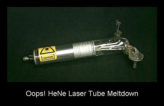
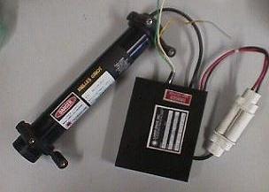
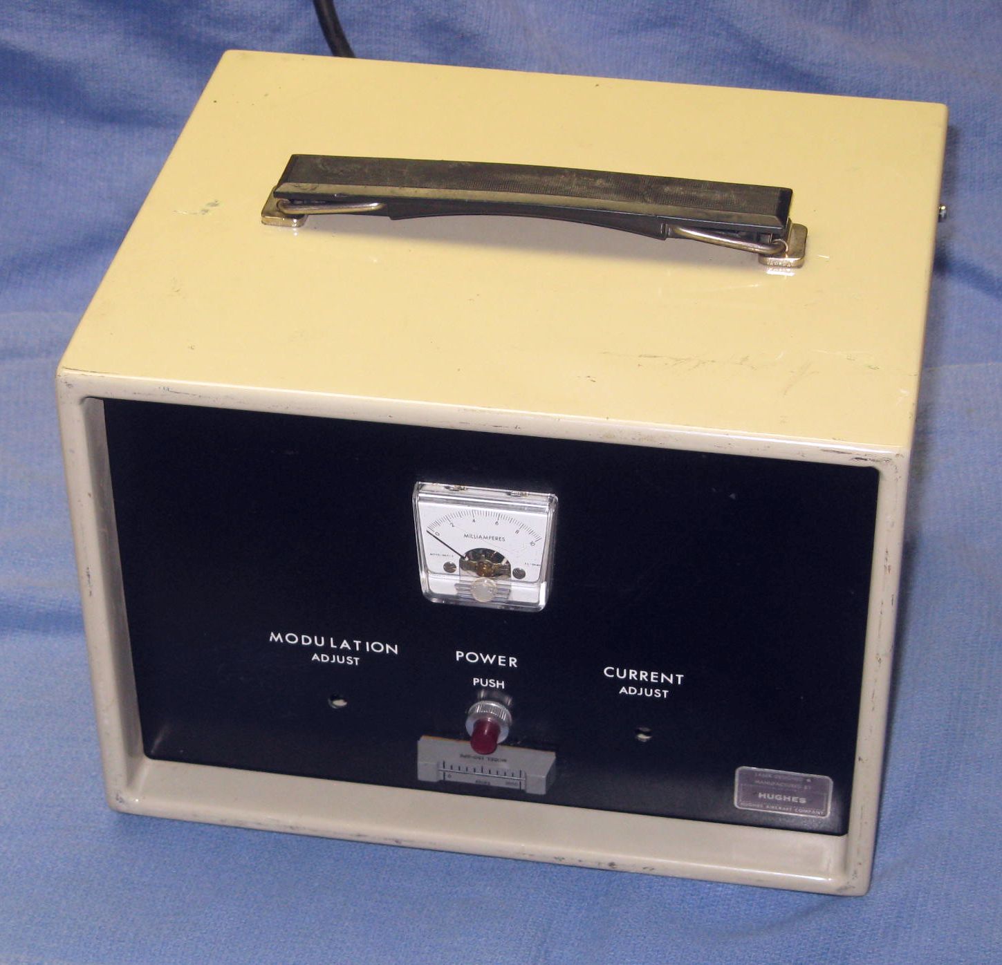
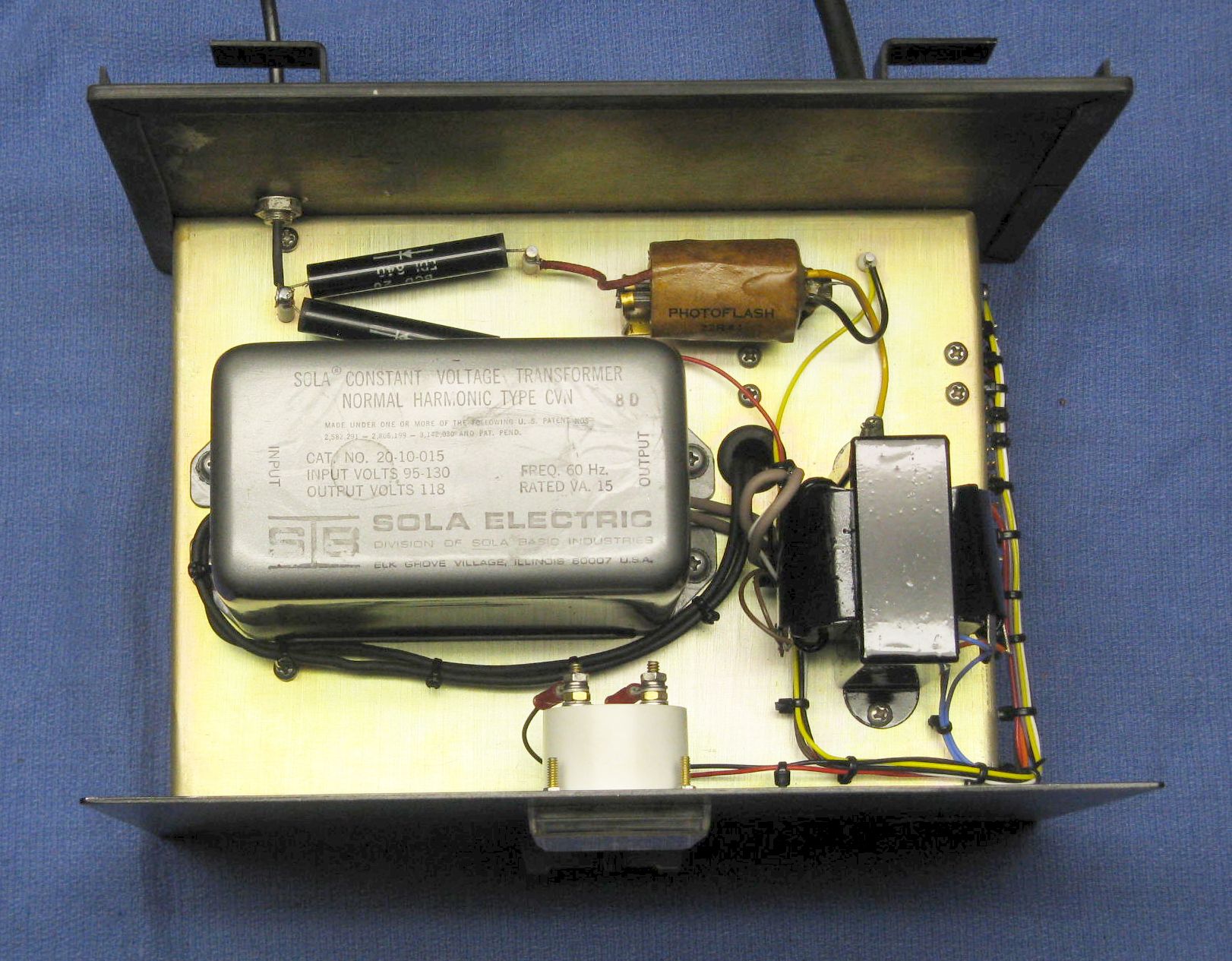
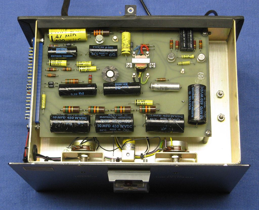
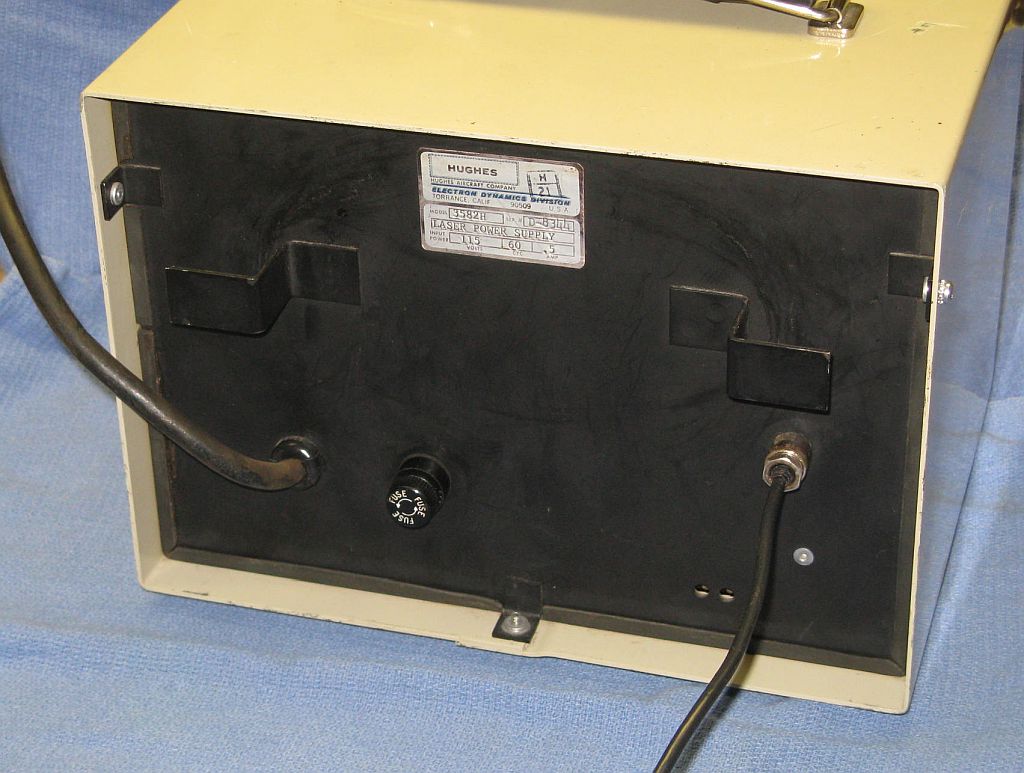
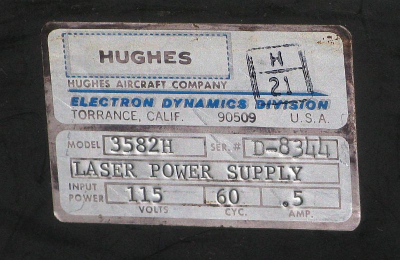
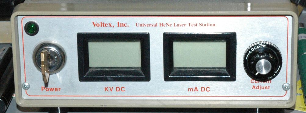
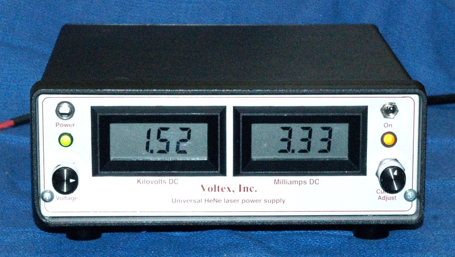
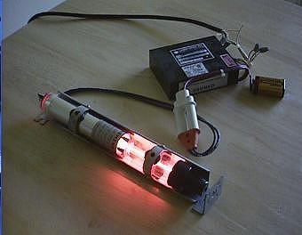
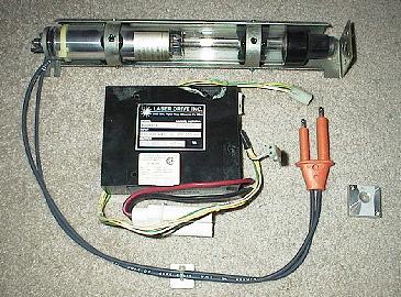
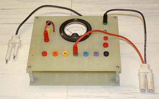
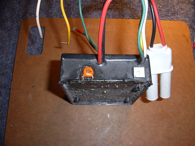
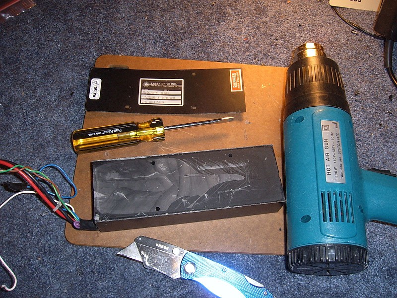
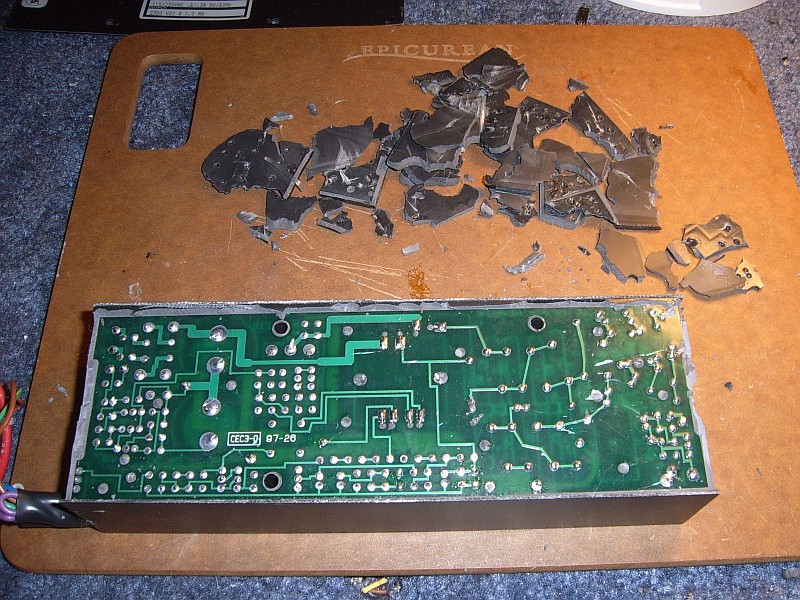