If all you have is a HeNe tube but no power supply, see the section: Testing a HeNe Laser Tube Without a Compatible Power Supply for ways to determine if the tube is good. The following applies to both bare HeNe tubes and laser heads though some of the inspection and/or tests will require removing the tube from any enclosure.
Several types of problems can prevent a HeNe tube from lasing properly or make it hard to start:
However, such damage could be an indication of a trauma that misaligned the mirrors - though this is quite unlikely - see the next paragraph.
Thus, if your HeNe tube appears to be glowing like a neon sign or fluorescent lamp (outside the bore) and starts at a very low voltage - perhaps half of the normal *operating* voltage specified for the tube - this may be the cause. A way of detecting it without powering the tube if the problem isn't obvious by inspection (it is hidden inside a laser head) or from the way the tube rattles, sight down the bore of the unpowered tube. In all likelihood, the capillary will now be misaligned enough such that one or both ends will be way off-center or not even visible. And, if it is still held in place by any metal spacer(s) that may be present, there will be no clear path through from one end to the other. Unfortunately, there is no way of repairing such damage. Where only a small part of the bore has broken off, the tube may still lase weakly if the broken part isn't blocking the internal beam path (or it can be jiggled such that this is the case). However, power will be way down.
However, in the latter case, the cathode can itself may not be secured to anything and may rattle slightly if the tube is shaken. As long as it is electrically connected to the end-cap or negative pin, this is of no consequence.
Note: if you have a high power (long) tube, mirror alignment may not be correct until the tube warms up and/or external permanent adjusters may be required to stabilize the mirrors. Without these, there may be no, low, or fluctuating power. Very slightly pressing on the mirror mounts - or even on various parts of the tube itself - (with a well insulated tool!) will result in a significant variation in power. There may also be a "This Side Up" label on the tube or head indicating the proper orientation for optimal performance. Parts in the tube droop due to gravity (not the electrons, ions, or photons!). This probably applies mostly to HeNe tubes that are greater than 15 to 20 mW, are "other-color" (e.g., green) tubes, and possibly only some types and condition. However, there could be some less dramatic effects with shorter tubes. In addition, just touching one side of the tube with your hand will cool it which may result in a noticeable power change due to the slight contraction which results in a minute but significant bending of the tube and chance in mirror parallelism!
See the section: Checking and Correcting Mirror Alignment of Internal Mirror Laser Tubes for more information.
Aside from manufacturing defects, one way for such a failure to occur is for a power supply fault to drive grossly increased current through the HeNe tube. It is possible for this to result in an abrupt termination of the discharge inside the bore and an inductive kick and huge voltage spike due to the wiring. With the bore momentarily unavailable, the only other path is for an arc through the glass barrier. Like the failure of a MOSFET gate oxide due to electrostatic discharge, once any breech develops, it does not heal! The addition of a spark gap surge protector sized to break down at just over the specified starting voltage may represent a prudent precaution when driving large expensive higher power HeNe tubes. Figure about 25 kV per inch - though this can vary considerably depending on the shape of the electrodes and environmental conditions.
This is one reason not to use a power supply much larger than needed for your particular HeNe tube. I found out the hard way when while violating my recommendation not to use a microwave oven transformer, this happened with a large (35 mW) HeNe tube due to a wrong connection which bypassed the ballast resistor. It was not pretty :-(. The HeNe tube is now good as a sort of high tech neon sculpture but not much else. I even found a defective power supply brick - inadequate start voltage - that powers the sculpture just fine. Now to put it all on a nice polished wood base. :)
See Color of HeNe Laser Tube Discharge and Gas Fill for some not too terrible renderings of a normal tube's bore and some typical problems. (Of course, your computer monitor has to be reasonably well adjusted for these to be at all accurate and even then they will not be quite the same as the real thing.) Discharge viewing must be through a glass part of the tube, not the mirrors since their transmission wavelengths will dominate. For an enclosed laser head, it may be necessary to remove one of the plugs on the side or the anode end end-cap (taking care around the high voltage!). The comments on the diagram about output apply to red HeNe tubes; orange, yellow, green, and near-IR HeNe tubes will likely produce no output at all unless the gas fill is nearly perfect. However, to maximize gain, "other color" HeNe laser tubes will likely have a slightly different discharge color due to modifications to the ratio of He:Ne, the isotopic purity of the gases, the pressure, and other unknown factors. So, before you blame bad gas, make sure your tube is indeed the normal red variety. As examples of other color tubes:
Various shades of red, blue, and white are symptoms of gas fill problems. Since the total amount of helium and neon in a typical 1 mW HeNe tube is much less than a cubic cm - if returned to atmospheric pressure, almost any leakage or contamination from gases leaking in or outgasing of the tube or seals, as well as helium leaking out, is significant and will likely prevent lasing. Where the tube is truly 'up to air', no discharge will take place, but the weak pink/purple discharge shown will result when the pressure is high enough for O2 and N2 ionization to dominate, and no amount of running will likely be able to clean it up. And the color may not be uniform in the bore, being bluish near the anode and pink/red further down. At high enough pressure, the discharge to the cathode may also be more like an arc than a glow resulting in erratic varying current even with the appropriate ballast. A state of affairs anywhere in between is possible and especially common for old soft-seal tubes.
Here are some descriptions of the discharge and effects on lasing. Unfortunately, it's very difficult to convey the actual appearance in isolated graphics. And digital photos have proven useless as the camera sensor response to the discharge glow with its discrete spectral lines is generally absolutely terrible.
A helium soak at 1 atm for one day for every year of tube age will often remedy this problem, sometimes fully restoring original output power or in some cases, even higher power if the tube was originally underfilled. But take care not to oversoak as that's not reversible without waiting for a long long time - that same 1 year for every day of He at 1 atm! However, it's often the case that tubes suffering from He depletion also have contamination from gases leaking in or from the seals.
Running the tube at normal current for anywhere from a few hours to several weeks may restore nearly full power due to the normal weak gettering action of the cathode. Some tubes like those from PMS/REO are more likely to respond to such treatment. But recovery to anything approaching full power - or at all - is contingent on there being virtually no hydrogen (H2) present as H2 is not gettered well if at all.
Extended running may help but the blue portion needs to disappear before anything else useful will take place. So far, my experience has been that the blue eventually takes over, the tube voltage increases dramatically, and the tube then goes to the next stage, below. :(
There is no hope of any recovery without refilling. And it's possible that sputtering at the cathode may have already caused irreversible overcoat of the mirror at that end of the tube.
There is no hope of any recovery without refilling.
However, without a monochromator or optical spectrum analyzer, you won't be able to see slight changes in discharge color and these may be enough to kill lasing (though normally, they will be obvious). And there can be both gas conatamination and loss of helium. In addition, tubes that are near end-of-life due to having been run for 10s of thousands of hours, may show a weaker and pinker discharge color due to lower pressure, or in extreme cases, a white-ish discharge from prolonged sputtering. (In the latter case, metallic deposits on the glass will usually be visible in the vicinity of the cathode - even on the bore or on the tube wall outside holes in the cathode cylinder. There's no need to spend more time with these tubes as they are not salvageable.) The only way to really determine if the color is correct where it looks reasonable and you happen not to have fancy instrumentation is to do a side-by-side comparison with an identical working HeNe tube. I say 'identical' because there can be subtle variations in the normal gas fill from different manufacturers (and from different color HeNe tubes). It may also be possible to take photos (digital or otherwise) of the two tubes (if you don't have two power supplies to run them simultaneously) and then compare those, but getting good color rendition may be a challenge.
Note also that the brightness of the discharge at the same current will almost always be lower with gas fill problems. This may not be immediately obvious unless a good and bad tube are run side-by-side but then it can be quite striking.
If the tube has a getter electrode (see the section: HeNe Laser Tubes and Laser Heads), check the color of the getter spot on the glass in its vicinity. The function of the getter spot is to combine with any unwanted non-noble gases (mostly oxygen and nitrogen) and should generally be black or metallic in appearance if still functional. A milky white, red, or brown color generally indicates that significant air leakage has occurred and the tube is probably no longer functional. Sure, it might be on the hairy edge but this isn't likely! (Note that sometimes a tube will be manufactured with a getter electrode but for whatever reason, it was never activated, the active material remained within its structure, or the active material is transparent. Thus, there is no getter spot, good or bad, and therefore no way to know - from this at least - whether there has been leakage. (For example, all normal (non-barcode scanner) Melles Griot HeNe laser tubes have a getter electrode but no getter spot regardless of gas-fill condition. So there's really no way to know their state of health for the getter.) It may be possible to reactivate the getter electrode by heating it by RF induction or some other means to drive off more getter material that may be present but (1) this is definitely for the advanced course and (2) the likelihood of helping the HeNe tube at this point is small unless the amount of leakage was very very infinitesimal.
(From: Don Klipstein (Don@misty.com).)
I have rejuvenated a couple soft-seal HeNe tubes by heating the getters, either with a glow discharge or a Solar furnace made with an overhead projector Fresnel lens.
(From: Sam.)
I have also revived both a red and a green Melles Griot HeNe laser tube using a jerry-rigged Solar furnace made from a $1, 7" x 10" plastic Fresnel lens intended as a reading magnifier. See the sections: HeNe Tube Lases but Color of Discharge Changes Along Length of Bore and Melles Griot GreNe with No Output for details.
Any source of RF power can be used to determine if a bare tube still has a reasonably low internal pressure (but not if it will lase). However, RF excitation cannot be used to test enclosed laser heads because it is generally not possible to view the inside of the actual HeNe tube and the (metal) case would prevent RF penetration or create other problems.
This approach can sometimes be an effective way for starting some HeNe tubes (even one that is normally hard-to-start) if the ionization reaches enough of the bore. It should certainly be able to substitute for the normal high voltage starting circuits for exposed capillary type HeNe tubes like those in laboratory lasers like the Spectra-Physics 124 and its cousins.
And other gas discharge devices like compact fluorescent lamps can be tested in a similar way, though the effect may not be as dramatic.
Conversely a known good tube can be used to confirm that a brick is trying to do something, though there could still be problems preventing it from working correctly.
Note: For metal enclosed laser heads, it will likely be necessary to remove one of the end-caps and the wire connection to the tube before being able to apply RF to it from a low current source like an Oudin coil even if the cable is known to be good. Otherwise, the capacitance of the cable will greatly reduce what reaches the tube and there may be no glow even if it is perfectly healthy.
CAUTION: Too much voltage will puncture the glass and ruin the tube. If using an HV or RF source that has an output terminal like an Oudin coil, it is best to attach a couple inches of wire to a metal part of the HeNe laser tube (like a mirror mount) and then touch that rather than the glass. And, use the lowest setting. If it doesn't glow with that, it's not going to do any better at 1,000,000 V. :) DO NOT apply it to the glass unless you are sure the voltage is less than about 10 kV. The dielectric breakdown voltage for the glass of HeNe laser tubes may not be that high! Use the metal parts and wire extension to be safe.
CAUTION: Damage may occur to the HeNe tube if the glow continues for more than a couple of seconds. Don't ask me how I found out (portions of the glass became hot enough to crack). Damage may also occur to you if your parents find out you were using the family microwave for this purpose. :-(
If the color is more toward the pink, lavender, or white, the gas fill may be incorrect or some air may have leaked in. Or, the tube may be end-of-life with significant sputtering around the cathode. See the additional paragraphs on gas-fill problems, below.
More extensive testing and even partial resuscitation of some HeNe tubes may also be possible while heating your hot chocolate. See the section: Using a Microwave Oven to Evaluate and Revive HeNe Laser Tubes for the exciting, but risky, details. :)
Note: In case your were wondering, this is not an effective way of exciting the tube to lase as the discharge intensity inside the narrow bore (capillary) where it counts is way too low. See the section: RF or Microwave Power Supply for HeNe Laser?. As a point of interest, the inventors of the HeNe laser, Ali Javan, William R. Bennett, Jr., and Donald Herriott, of Bell Labs, attempted to use a magnetron for excitation of their original laser in 1960 - and the quartz tube melted! This approach would probably have been quite effective for their wide-bore design if it were not for this minor amount of collateral damage.
However, since you will no doubt insist on experimenting, (1) do so with something other than the family microwave and (2) consider using a Variac to drive the primary of ONLY the high voltage transformer of the microwave generator (fed from the microwave oven's controller). For safety, DON'T attach it externally, DON'T bypass or disable any door interlocks, and make sure the cooling fan is always powered from the full line voltage. This modification will allow some control of power (relatively safely) so that your experiments will be at least less likely to destroy things too quickly. (However, note that the filament of the magnetron is also powered from the HV transformer, so this will limit the useful range and result in some time delay for power to stabilize.) My guess is that adjusting the knob somewhere between 60 and 80 percent, and full voltage will result in 0 to 100 percent of microwave power (the magnetron is a non-linear device which has a threshold voltage below which no output is generated). Then, after you have tried basic nuking of your sacrificial HeNe tube, see what effect a short length of wire attached to the anode (to act as an antenna) will have on excitation of the central bore, add shielding, adjust tube position, etc. Have fun but take care!
Note that if you can sustain a discharge but it is the wrong color, you may have one of those really old Epoxy sealed tubes that leak and air has leaked in or helium has leaked out. The tube is probably not worth repairing but might make an interesting wall hanging (power optional). However, sometimes, revival is possible:
If you have a spectroscope (see the section: Instant Spectroscope for Viewing Lines in HeNe Discharge), it is easy to see if this is the case as the neon lines in Bright Line Spectra of Helium and Neon will be predominant.
One quick test that can be performed visually with a simple diffraction grating to compare the brightness of the neon 585.25 nm line and the helium 587.56 nm line. These are (or should be) two bright adjacent yellow lines. If the mix is correct, these two lines should appear equal in brightness. OK, maybe it isn't so simple since finding those lines by eye could be a rather large challenge. :) However, they can be seen in Bright Line Spectra of Helium and Neon although the helium line is much brighter in this rendering.
It doesn't take too many of those nasty H2, N2, or O2 molecules to affect lasing adversely since they have many energy level transitions much lower than the helium transition to get excited. With just a small amount of unwanted gases, there may still be an output beam, though it will probably be much weaker than expected. One unusual characteristic of such a tube may be that the discharge color is correct at the anode-end of the bore but wrong toward the cathode or may vary in some other way. See the section: HeNe Tube Lases but Color of Discharge Changes Along Length of Bore.
With incorrect pressure and unwanted gases, the tube voltage could be quite different than normal (low or high). The tube cited above had a slightly lower (perhaps 100 to 200 V) operating voltage before having its getter activated. Where the discharge voltage has increased, the tube will dissipate more power while operating, and thus also run hotter than normal HeNe tubes. Small amounts of oxygen and nitrogen may increase the starting voltage substantially as well. If you can measure tube voltage (see the section: Making Measurements on HeNe Laser Power Supplies), compare it with your tube's specs (see the section: Internal Mirror HeNe Tubes up to 35 mW - Red and Other Colors).
And, I've seen exactly one (1) HeNe tube that had the mirror coating on one (1) of its mirrors totally blown away, most likely due to damage resulting from a loose cathode-mirror mount connection and the discharge taking place inside the mirror mount tube itself.
See the section: Damage to Mirror Coatings of Internal Mirror Laser Tubes for more details.
This seems to be particularly common with Melles Griot (and similar) tubes using a "start-tape" running from the anode almost to the cathode along the cylinder wall. Any condensation will cause problems. I recommend disconnecting the start tape from the anode and removing it entirely by carefully tearing it or pushing it way back inside so the end is at least an inch away from the anode connection. I have never seen the start tape make any difference in starting time though Melles Griot claims some statistical benefit. :)
Similarly, the dropout current may have increased to the point where the power supply current setting is marginal. Increasing the operating current may allow the tube to continue to operate for awhile but it's probably nearing the end of its useful life.
For more on measurable parameters of a HeNe laser tube that can be used to assess its health, see the sections starting with: HeNe Tube Use and Life Expectancy.
It probably doesn't make sense to spend a lot of effort, time, or money to revive a 1 mW HeNe tube that can be replaced for $15. However, if you are ambitious or a new tube cannot be substituted easily (e.g., due to mounting restrictions), see the sections starting with: Repairing Leaky or Broken HeNe Tubes.
First, you need to determine the tube's power connections. See the section: Identifying Connections to Unmarked HeNe Tube or Laser Head if you aren't sure.
There are many ways to power a HeNe tube for the purposes of seeing if it produces a beam. Almost anything that can provide enough voltage to get a few mA through the tube will result in at least a momentary flash of laser light out the end if the tube is good. There won't be any way of determining output power or whether the tube meets specs, but the knowledge that it lases at all may be enough to take the next step - the purchase or construction of a proper power supply.
It is easy to use the family microwave to see if the tube is gas-intact if the tube will fit inside. See the section: Using a Microwave Oven to Evaluate and Revive HeNe Laser Tubes. While this won't tell you if the tube lases, if it fails this test, there is no need to go further.
To test for lasing, current must be passed through the bore of the tube. A couple of options for a quick test power supply are:
Even a high voltage AC supply with appropriate current limiting can be used safely for a few seconds only. (I've been sent HeNe laser tubes which have been operated on AC because the owner copied some power supply design off the Web and didn't know any better. The output power (what of it there was) gradually declined over a few minutes and then there was none.) And even with the rectifier voltage, the tube will be restarting once per cycle which is hard on it so don't run that for too long either. None of these are suitable to operate a HeNe tube continuously unless proper filtering and starting circuitry is added to turn it into a proper HeNe laser power supply.
Don't go overboard though: Too high a voltage applied in the wrong place can arc straight though the glass at which point you have a rather boring high-tech sculpture. :( A very high current can also damage the tube very quickly, thus the need for the current limiting ballast resistance.
With these power supplies driving the tube, if there is any output beam, even if it is weak or in the form of short flashes, the tube is probably good. However, there is no way to tell if it meets specs since HeNe laser output power is only maximum over a narrow range of tube current and these quick test power supplies are at most controlling only average current, not instantaneous current as would be the case with a real HeNe power supply. But, at least you know the tube isn't dead.
Wire the output of the transformer in series with the rectifier(s) and ballast resistors. The positive output goes to the anode of the HeNe head or tube; the negative to the cathode. It doesn't matter whether the laser has an internal ballast resistor. Insulate everything VERY well. :)
Powering the laser should result in flashes of coherent light, probably at the power line frequency (60 or 50 Hz). The amount of light will not be that impressive even with a perfectly good high power laser since the current is nowhere near optimal for any length of time, if ever. However, the presence of laser output would confirm that there is life.
WARNING: Since the centertap of the transformer secondary should be grounded, both outputs of the power supply will be floating with respect to ground. Take care.
Just connect the output in series with a 1M ohm resistor rated for 15 kV (like the one above) directly to the tube or the Alden connector of a laser head. On the devices I tested, the polarity of the output is not labeled, but the positive output is the one closer to the side with the input leads. Red is the positive input.
It's likely that these can also be used for powering small N2 lasers and as simmer supplies for lamp-pumped solid state lasers. And for testing arc lamps and flashlmaps, and all sorts of other high voltage low current devices.
In this condition, the tube still lased at a power level which relative to its rated output, is approximately proportional to how much of the bore has the correct color. In this sample, about 2 mW for a tube specified at 4 to 5 mW. I don't believe the starting or operating voltage has been affected very much.
The explanation that makes the most sense is that due to the discharge current in the bore, the few N2 and O2 atoms (and any other party poopers that may have entered without an invitation) are being ionized and pushed toward the cathode of the tube leaving the desired helium and neon atoms to play at the anode-end. The contamination, whether due to a manufacturing problem or an air leak, is so marginal that nearly all of the unwanted atoms are swept from about half the length of the bore. However, the other HeNe tube I have like this had the color change in the exact opposite direct - correct at the cathode but blue-ish-pink at the anode, also reduced power. I now suspect that it may have been internal contamination. More research is needed. :)
Another unusual characteristic of the Northern Lights tube was that the output power (what of it there is) peaked at a current somewhat higher than expected (8 mA as opposed to the 6 or 6.5 mA typical of this size tube). I don't know whether this is simply due to the overall contamination or that more of the nasty unwanted ions being swept from the bore when running at a higher current.
This tube had an unfired getter which provided a means of cleaning up the contamination without a refill. A few weeks later, I got around to making the attempt. And the results are.... See the section: Repairing the Northern Lights Tube.
However, it could also be that your power supply operating voltage, ballast resistor, and other factors may need modification. Of course, if the system used to work reliably and suddenly died, an actual power supply or wiring problem is most likely though a dead HeNe tube is also possible especially if the system has been unused for several years. But don't overlook the unlikely, but not impossible situation where your line voltage is low for some reason! Check it first. The discussion below is somewhat oriented to the situation where a HeNe tube or laser head is being assembled with a power supply (or parts have been replaced) and the combination just doesn't want to work properly. However, some of it also applies to actual failures as well. Where the power supply itself is suspect, see the section: Power Supply Measurements, Testing, Repair.
There are several types of possible behavior depending on how well the power supply, ballast resistance, and HeNe tube are matched up, and if any of these as well as the wiring, are faulty. You first need to determine if the discharge is being initiated at all. If the starting voltage is adequate, there will be momentary flashes that may be extremely short and weak and only visible in a darkened room but operating current may not actually follow. Under marginal conditions, operating current will flow in response to the starting voltage but won't be maintained. These flashes will be brighter and longer in duration. The result may be a nice flashing laser. In fact, this progression is exactly what will be seen when operating a HeNe laser tube from a power supply on a Variac as the voltage is increased: Short flashes followed by longer flashes and at some point, a steady beam.
WARNING: If your HeNe tube doesn't start after a reasonable length of time (like a minute), don't leave the power supply on overnight in a futile attempt to get it going. Starting is a stressful time for power supply components, especially some wide compliance designs, and an extended period with the very high starting voltage on parts of the circuitry may result in total failure. It could also result in electrical breakdown (arcing) inside the laser head or cable. If the laser is flashing, this may be ultimately bad for the tube as well. Turn it off, step back, and try to determine what is wrong.
Where the power supply components and/or wiring is exposed and subject to dirt and grime, first, carefully clean everything to eliminate possible sources of electrical leakage, which can affect operation, particularly the very low current starting circuit. As an experiment, try warming up the unit (which drives off conductive moisture) with a hair dryer or heat gun on the 'low heat' setting. This may enable it to start more easily confirming the need for some housekeeping. :)
First, vacuum and/or dust it off with a soft brush, then use mild detergent and water followed by isopropyl alcohol (rubbing or medicinal is fine as long as there are no additives). Give it ample time to dry completely. The hair dryer or heat gun can be used to help it along. You may now find that your starting problems have disappeared!
If your tube or head has an external starting loop or tape (see the section: Power Requirements for HeNe Lasers), it must be cleaned thoroughly as well (or maybe it has become disconnected, is broken, or has shorted to the case!).
There is also a possibility that something else is shorting out the power supply, possibly only when enough voltage is applied so it won't show up with an ohmmeter test. Sometimes, the ballast resistor inside cylindrical laser heads will arc to the case. This can be checked with an HV insulation tester or more easily for most people, by removing the end-cap(s) and visually inspecting (as well as smelling!) for evidence of arcing, or by disconnecting the anode wire and driving the tube directly from the power supply with an external ballast resistor.
Assuming none of this helps, there are three types of behavior: (1) No action of any kind, (2) an occasional flash possibly at random intervals, and (3) a periodic flashing laser which never settles down to normal steady operation. However, the behaviors and their causes are not really always independent so read through all of the possibilities before replacing components or ripping your system apart!
This generally means that the starting voltage is inadequate for the tube or isn't reaching it, there are other circuit problems, or the tube is bad. Tubes with longer and narrower bores (capillaries) will generally require greater starting voltage and your power supply may just not be up to the task. While tube manufacturers generally specify a starting voltage of 7 to 10 kV (or higher), typical tubes will fire with 3 to 5 times their operating voltage. Thus, a tube that runs on 1,700 VDC will probably start on 5,400 to 8,500 VDC.
In some cases, shining a light into the tube will allow it to start, and a few HeNe lasers have either had an incandescent lamp (really old LaserDisc players) or a high brightness LED shining on the tube, usually near the anode-end. HP/Agilent metrology laser tubes often respond to an LED, but that's only an after-market option. ;-) For common laser head cylinders, clear out one of the tube mounting holes toward the anode-end and poke the LED in there. It can be secured with clear RTV and then covered with Kapton tape. Note that the anode-end is not necessarily where the cable attaches. It may be necessary to check both ends so see which one is not blocked by the cathode can. A white LED with 2K ohm resistors on each side should provide adequate brightness for use with a 12-24 VDC power supply. A suitable DC voltage in that range should be available inside any instrument where rapid starting matters.
In the case of an enclosed laser head with a HV (e.g, Alden) connector, HV cable, and internal (potted) ballast resistor, there may be a breakdown in one of these components and it may only show up when starting voltage is applied (not with an ohmmeter).
Allow the laser to attempt to start for 15 or 20 seconds and turn off the power supply. Immediately pull the Alden connector out of the power supply and discharge it on a metal surface. A nice long (e.g., 1/4") spark indicates that the starting voltage is probably adequate from the power supply and breakdown in the wiring is not likely. If there is little or no spark, either the starting voltage is low or zero, or there is a broken connection between the connector and the tube resulting in not much capacitance to store a charge.
Here are two more tests for this situation:
If the tube now starts, one of the original components was faulty (most likely the potted ballast resistor assembly if the negative connection runs through it) and this will need to be replaced.
Assuming the power supply and wiring check out and the tube is good, the only solution is to boost the starting voltage or use a different type of starting circuit (inverter instead of voltage multiplier, for example).
Note that newly manufactured tubes requiring more than a second or so to start using a compatible power supply are usually rejected as defective and may end up in the hands of surplus dealers who may sell them as 'new' even though they don't meet specs. Thus, you may be more likely to end up with one of these hard starting tubes!
And, it may not only be high mileage tubes. I recently discombobulated (translation: disassembled to harvest its organs) a vintage HeNe laser-based LaserDisc player and found a little incandescent lamp buried near the bore of the laser tube. It is even documented in the service manual (which includes the assembly procedure for the optical pickup or "slider" as Pioneer calls it), but there is no discussion as to its purpose. However, the way it's wired in suggests that the lamp is not in the original design. The only possible explanation is that it was there to help a possibly hard starting HeNe laser to start. It must have been included to be able to use tubes that otherwise would fail to start quickly enough. Nonetheless, for a manufacturer include a light bulb to aid starting in production units is so strange. I did have a professor whose motto was "If it works, use it". :) That's also my motto when dealing with slow starting HP/Agilent metrology lasers like the 5501B, 5517B, and others, which have a similar quirk: With the cover off, they would start normally, or at least fairly quickly. But with the cover on, they could take a minute or more to start. I now routinely add a high brightness LED shining on the back-end of the laser tube if the starting time is so excessive that it might be flagged as an error.
A high brightness UV LED has been found in rear plate of a REO model 38539 stabilized HeNe laser head whose function could only be to aid in starting. It's like the LED was not original equipment though due to the hacked way it was installed.
Based on tubes I have tested, the starting voltage is much lower with the anode and cathode connections interchanged. However, the voltage drop across the tube when running with reverse polarity may be higher than with correct polarity. For tubes where the normal anode is the mirror mount, it may be only modestly higher. But for tubes with a pin for the (normal) anode connection, it could be 2 or 3 times the normal operating voltage. And for those, while it will lase initially, output may decline to zero in a few seconds, presumably due to heating of the pin affecting the alignment due to heating of the pin or anode mirror stem, and the power will recover fully once it cools. Thus, the tube may not run within the normal operating voltage range of your power supply even if the discharge is initiated - more likely it will just pulse.
Nonetheless, even if it just pulses, at least you know the tube is not totally dead. If the tube is otherwise undamaged, there should also be an indication of (at least weak) laser output from the business end of the tube. Perhaps, all you need is a power supply with higher starting and/or operating voltage. An inverter type starter using a flyback transformer appears to be particularly good for hard-to-start tubes. Unfortunately, I do not know of any reliable way of determining the likelihood of success without actually trying it.
I have one 5 mW HeNe tube that requires (depending on its mood) as much as 15 to 20 kV to start (it should be less than about 10 kV). However, once started, it runs with a normal operating voltage of about 1,800 VDC.
In addition, with some tubes, just running current through them for a few seconds will "condition" the internal parts so that if the correct polarity is applied ASAP after doing this stunt, the tube may start instantly. I have built a Male-Female Alden polarity reversing cable for just this purpose. ;-) Tickling the anode with a hand-held Tesla coil on its lowest setting may also be successful
WARNING: Do not let the HeNe tube run for any length of time with reverse polarity as damage may occur due to heating and sputtering at the anode end of the tube. Didn't I say that already? ;-)
This sort of behavior is probably more likely with a pulse type starter but can occur with other types as well. What is likely happening is that the energy is insufficient to fully ionize the gas inside the bore of the HeNe tube so the discharge doesn't 'catch'.
In addition to the other possibilities listed above and below:
What happens is that the discharge is initiated but the voltage drops too much at the tube anode and the discharge goes out. This cycle repeats resulting in a flashing HeNe laser.
To produce a stable discharge, the following must be satisfied:
These factors are not independent. Since the negative resistance and sustaining voltage of the tube are not normally specified and depend on current, some amount of trial and error may be required to achieve consistent stable operation but in most cases it really is very easy.
Cycling behavior can be due to several factors:
If the transformer or inverter drops too much under load, the tube voltage may fall below the minimum for the tube/ballast combination as soon as it starts. This cycle will repeat continuously or it occasionally may catch.
Use a higher voltage and larger ballast resistor, and/or increase the uF value of the main filter capacitor (and/or the one in the DC supply to an inverter type supply as well if it isn't regulated).
Minimum capacitor values for less than 5 percent voltage ripple (typical voltage and current requirements):
Actual ripple in the current to the tube may be several times greater than this since it depends on the change in voltage with respect to the total effective resistance of the PS+tube+ballast resistor combination). However, the resulting ripple in the optical output power will be 2 to 10 times lower than the ripple in the current depending on operating point. The lowest will occur around the tube's optimal current specification.
For an unregulated power supply, increase the operating voltage and/or decrease the ballast resistance.
For a regulated power supply, decrease the ballast resistance so that the voltage for the desired operating current falls within its compliance range.
Shorten the wiring - minimize the distance between the power supply and ballast resistor, the ballast resistor, and tube anode, and don't use long runs of high voltage coax (which may have higher capacitance). Increasing the energy of the starting circuit slightly may help as well.
Also see the sections: How Can I Tell if My Tube is Good?, About Hard Start HeNe Tubes, Testing a HeNe Laser Power Supply, Power Supply Construction Considerations, and Adding a Start Wire.
As far as I can determine, the fundamental physics behind this phenomenon may not even be well understood by the major laser companies. The only meaningful data is statistical, because even a given tube with a given power supply may have dramatically different start times from attempt to attempt, as will tubes built side-by-side through the entire production process.
Tubes that are kept in dark cold environments for long periods of time don't tend to start well. But, once one of these tubes is started successfully, restarts will likely be instantaneous, or at least reasonably quick. However, left overnight, they will revert to being uncooperative.
Also lower fill pressures and cleaner tubes make for hard starting - not to mention power supply variables.
Some manufacturers (e.g., Melles Griot) use a conductive 'start-tape' running the length of the tube attached to the anode electrode to aid in starting. It's not even really proven that this shortens starting time (and I've found that it can be a source of electrical breakdown problems). I've never noticed any difference in the speed of starting after removing the start-tape. Uniphase had a pointed "field emission" electrode inside the anode mirror sleeve to aid in starting but it isn't obvious that it made any statistical difference either. There has even been talk of placing a trace of radioactive gas (as had been used in neon indicator lamps and glow tube fluorescent starters), but this of course would probably not be a popular idea today!
A given production line may still have hard-start related yield problems from time-to-time (which kind of suggests the Ph.D physicists don't understand it). Funny thing is, no one can tell anything that's different on a hard-starter versus a regular one.
For some hard start tubes that otherwise run well without current drop out problems, adding a start wire directly from the anode with a few turns wrapped around the tube near the cathode may help starting dramatically. For example, on Spectra-Physics side-arm laser tubes, there is a section next to where the cathode attaches to the main bore where adding a start wire may work quite well. This allowed an SP-155 which would almost never start at normal line voltage to start instantly first time every time.
Use a well insulated wire connected before the ballast resistors. Wrap the end a few times around the narrowest section of the tube near the cathode or use a metal clip. Some experimentation may be required. Just try not to zap yourself excessively during testing. :)
However, if used with a some linear power supplies having a voltage multiplier starter (probably without a final diode/filter stage), the tube must run stably substantially above its lower current dropout point or else the start wire will tend to turn the tube off as well as turn it on and the result will be a flashing laser, which is usually not a good thing. Adding a HV diode in series with the start wire might help, but I haven't tried it.
As added protection for you and the power supply, instead of connecting the start wire directly to the raw high voltage output, install a series capacitor with bleeder. I would suggest 1 nF with a 100M ohm resistor across it. Both should be rated for the peak starting voltage available from the power supply, typically 8 to 15 kV.
And, for other-color HeNe tubes which have much lower gain for a given length than red HeNes, all of the above may apply. The following comments were prompted by questions about a non-lasing short green HeNe tube (similar to a Melles Griot 05-LGR-024, 215 mm in length:
(From: Lynn Strickland (stricks760@earthlink.net).)
Those things are touchy, touchy, little SOBs. They usually have an almost flat HR and OC combination. If it does lase, it will probably be a few tenths of a mW at best. Probably have to walk the beam AND tweak both ends for any hope. Try some magnets too, for 3.39 micron suppression. In general, low power greens are a bitch to tweak.
Note that the green discharge is more 'pink' (red tubes more 'orange'). Fill mixture is a little different, but the different color mostly due to lower fill pressure - which is why greens have shorter lifetimes than red.
For example, I found that some recent samples of the popular Melles Griot 05-LHR-911 HeNe laser head, rated at 1 mW minimum power output, were all made with neutral density filters to assure that the maximum power output was less than 1.5 mW. With the filters removed, it jumped to between 1.8 and 2.1 mW! Apparently, the filters were individually selected to get the lasers as close as possible to 1.5 mW without exceeding it since their attenuations were not all the same and the weakest laser in the batch (with the filter) actually ended up having the hottest tube.
More likely, the manufacturer accidentally used too large a bore for the length of the resonator and the mirror curvature. For example, if this is a green (543.5 nm) HeNe laser, they may have used a bore sized for a red (632.8 nm) HeNe laser by mistake resulting in a mode diameter that is too large. Or, it might have been designed on the hairy edge, size-wise, in an attempt to get as much power as possible out of the tube and the engineers weren't lucky that day. With a correctly sized bore, slightly incorrect mirror alignment would result in lower power but maintain a TEM00 beam profile.
If you had been the original owner, the laser might have been replaced under warranty. As it is, you now have what I generally call an "interesting" laser. :) Or, since the specifications are often only with respect to "95% mode purity", if the hole represents less than 5 percent of the power, maybe it's considered acceptable, though I can't imagine anyone being entirely happy with a laser that's supposed to be TEM00 having a hole in the middle of the beam unless all they care about is the number of photons per second!
However, even with too wide a bore, it may be possible to adjust the mirror alignment to obtain a TEM00 beam. Gain access to the cathode-end mirror mount (to avoid a shocking experience) and allow the laser to warm up completely in the orientation that will be used. Aim the laser at a screen of some sort like a white business card, and gently press sideways on the mirror mount from orientations every 45 degrees or so (top, bottom, left, right, and the diagonals). Closely examine the spot shape to see if it pops into TEM00 at any time while still maintaining near-maximum power. If it does, it should be possible to adjust the alignment as described in the sections starting with: Problems with Mirror Alignment. A power meter will be useful to assure that the output power is still near maximum. It may in fact end up being maximum with the TEM00 beam, though some other beam profile when cold. Very likely, the alignment will be very critical. Several attempts with multiple warmup cycles (to allow the metal mirror mount stems to settle in) may be needed to achieve consistent behavior. I adjusted a green HeNe laser head that formerly had a doughnut beam. It now starts out TEM01 but becomes a beautiful TEM00 once it warms up, and significantly exceeds spec'd power. But I haven't decided whether a consistently interesting doughnut beam or a boring high quality TEM00 beam only when warmed up is preferable. :) CAUTION: You could make the laser worse or dead by attempting mirror alignment. So unless you've done this successfully before, it may be best to leave well enough alone and enjoy the unusual behavior. There's nothing else you can do about it!
See the section: Basic HeNe Laser Power Supply Considerations.
However, a faint clicking or snapping sound may actually be normal during starting if the power supply uses a pulse starting technique or is cycling a PWM controller attempting to start.
Also see the sections: How Can I Tell if My Tube is Good? and Starting Problems and Hard-to-Start Tubes.
A different power supply or slight adjustments or modifications may make your HeNe tube happy, at least temporarily. However, where the HeNe tube is an inexpensive vanilla flavored variety, replacement may be the easiest solution if it turns out to be marginal. :-)
The symptoms are that the tube may start normally but then go off and restart, possibly quickly and unpredictably. One possible cause is a bad internal connection between the cathode can and its attachment to the mirror mount where the negative lead of the power supply is hooked up. The type of construction susceptible to this malady is where a 'nipple' on the end of the aluminum cathode can is swaged (pressed/squished) into the mirror mount rather than actually being attached by spot welding or via a spring contact. After many thermal cycles, the swage can loosen resulting in intermittent contact especially as the tube heats and parts expand. (This is sort of the same problem that aluminum house wiring can have if improper termination techniques or devices are used, but in that case, the consequences can be much more disastrous!) Any sort of high resistance increases the required tube voltage since the mirror mount has a higher 'cathode fall' voltage drop. The discharge will likely go out and the power supply will then attempt to restart. In some cases, the discharge may strike to the mirror mount itself (look for a glow near the mirror) and if this persists, will eventually destroy the mirror. (See the section: Damage to Mirror Coatings of Internal Mirror Laser Tubes) After the tube warms up sufficiently, since aluminum expands faster than steel or Kovar, the problem may disappear once the connection tightens. However, until then, the intermittent contact and many restarts is hard on the power supply and nearby mirror.
Assuming the power supply and tube are properly matched and the power supply isn't defective, this is a defective HeNe tube. No cure is possible. This is a relatively unusual problem (I've only seen it in two (2) HeNe laser tubes so far) so first check external connections and make sure your HeNe tube and power supply are properly matched. If its maximum voltage is marginal, as the tube heats up, the voltage drop may increase just enough to result in erratic behavior. However, one possible difference between this and a bad cathode connection is that with the latter, the condition may clear up once the tube heats up since the expansion of the aluminum cathode will improve contact. The marginal voltage situation will just get worse. The power supply itself could also be defective. The easiest way to determine which is at fault is to swap the PSU and/or tube with known good units.
I've seen this malady on a few older Melles Griot HeNe lasers. On newer ones, a thin metal conductor has been added - presumably in response to this type of failure - connecting the spider/bore support (which is in good contact with the cathode can) directly to the end-cap. It is spot welded at both ends.
Also see the section: Unstable or Flickering HeNe Tube.
The male pins can be cleaned with a file or fine sandpaper. The female contacts can be tightened by wedging a small flat-blade screwdriver inside the connector between the side and the plastic contact support. Entire replacement Alden connectors are readily available or can be salvaged from dead laser heads or power supplies. To avoid the possibility of arcing or a shocking experience, use at least 2 layers of heat-shrink tubing for insulation with a minimum of 3/4" beyond the bare wire sections, and stagger the splices. Add another layer of heat-shrink over the completed splices.
And replacements are available (other than from salvaged lasers!). See Alden Connectors Catalog.
Note that if the discharge is actually going on and off, the cause is entirely different - an incompatibility with the power supply, incorrect ballast resistor, low line voltage, etc. See the section: Unstable or Flickering HeNe Tube.
However, sometimes you will find a laser that exhibits significant periodic variations in output intensity even where the discharge is perfectly stable. There are two types of phenomena depending on the period of the power cycles:
These result in fewer longitudinal modes having sufficient gain to sustain the lasing process. As the resonator length changes, these lines move with respect to the gain curve of the lasing medium. Where there is cyclic variation in output power, only a very few lines are of sufficient gain to sustain lasing and then only when they are near the peak of the gain curve. The tube stops lasing entirely when there are no lines with sufficient gain to sustain oscillation. See the section: Longitudinal Modes of Operation.
High mileage tubes with low gas pressure and tubes that are leaky (usually soft-seal but not always) with a contaminated gas fill may produce a very weak beam that comes and goes in a similar manner. (Such a tube may also be hard starting or erratic on its normal power supply independent of the slow fluctuation in in output power.) Very short and very long tubes are more susceptible to these effects. Short tubes have fewer possible longitudinal modes available so as the gain falls off with use, the variations become more pronounced. Similar behavior may be present with some yellow and green tubes since their gain is so low to start with and everything is critical.
For longer HeNe lasers, in addition to the mode sweeping at the output wavelength, there may be a longer period power variation due to power stealing by the unwanted 3.39 um line if it isn't adequately suppressed by bore/mirror design or magnets. This would occur at a rate of 0.632.8/3.391 as fast as the 632.8 nm mode cycling (for a 632.8 nm laser). If the laser output power is recorded over time, one would see the effect of the 3.391 um superimposed on the shorter one but it won't show up as a smooth variation - more like mountain peaks appearing within rolling hills. :) But the hills may be rather lumpy because the gain bandwidth of neon at 3.39 um is much narrower, there will be fewer lasing modes there.
To confirm, try adding some medium strength magnets along the tube or head. Experiment with the number and orientation of the magnets but a half dozen with alternating polarities along one side of the tube are typically adequate. If the magnets reduce the amplitude of the 3.391 um fluctuations (and probably increase the average output power by up to 25 percent or more), poor design is the likely cause. Among other things, the mirrors are too reflective at 3.391 um. Aside from installing the magnets permanently, there isn't much that can be done.
A similar sort of varying intensity behavior will result if a polarizing filter is placed in the output beam of a randomly polarized HeNe tube or a HeNe tube that is supposed to be linearly polarized but isn't working properly because its internal Brewster plate has fallen off or its polarizing magnets have weakened or are mispositioned. However, in this case, what happens is that as the laser switches between longitudinal modes and/or the mirror alignment shifts ever so slightly, the polarization angle and thus the output intensity of the beam may change significantly. This is perfectly normal for a randomly polarized tube but indicates a problem with one that is supposed to be linearly polarized. See the section: Unrandomizing the Polarization of a Randomly Polarized HeNe Tube.
(From: Daniel Lang (dbl@anemos.caltech.edu).)
"The typical HeNe laser's gain curve is wide enough for 2 or 3 longitudinal modes to oscillate simultaneously. As the laser warms up, the cavity expands, causing the modes to decrease in frequency. When a mode gets too low with respect to the HeNe linewidth, it goes out and after a bit, a new one appears on the high side of the linewidth. This typically has a period of 3 to 10 seconds. I suspect that an old laser that is doing this is down to 1 or 2 modes due to reduced gain and may be approaching 0 or 1 mode, causing a visible intensity modulation.I noted a similar problem when using a HeNe for Laser Doppler Velocimetry. In this case we were seeing a low level intensity modulation that would start at approximately 60 Khz, sweep through zero and back to 60 Khz and then disappear for several seconds before starting again. The entire cycle repeated in approximately 5 to 10 seconds. The longitudinal mode spacing for our laser was 385 MHz. The sweep between 0 and 60 kHz only appeared when the laser was operating in 3 modes. The frequency difference between modes 1 and 2 was not quite the same as the difference between modes 2 & 3 except when exactly symmetrical (amplitude of mode 1 = amplitude of mode 3). We were seeing the difference of the differences! The longer interval free of intensity modulation occurred when only 2 modes were oscillating."
For more information on this phenomenon, see the section: Longitudinal Mode Pulling.
A simple test to confirm thermal gradients as the likely cause is to gently press on each mirror mount (careful: high voltage!), or perhaps even in the center of the tube if it is supported at each end. If power can be restored to near normal no matter what its value by doing this (the direction and force required will not be constant), it is likely a thermal problem.
Therefore, it is important to mount long higher power HeNe tubes both at the recommended locations (usually by gently clamping the glass near the ends of the tube) and in a case to promote temperature uniformity and isolate it from convection currents. The alternative is messy: Active feedback to monitor output power and tweak the mirror mounts with a servo system. :) Long yellow and green HeNe laser tubes are particularly susceptible to very erratic behavior as a result of thermal effects. If not mounted in a suitable enclosure, it may not be possible to achieve mirror alignment that results in stable output power and fluctuations of 100 percent could result. In other words, the beam may vary in output power even to the point of disappearing entirely over a period of a few minutes. In fact, Melles Griot will not even sell yellow, green, or other low gain HeNe laser tubes by themselves (not mounted in an enclosure) as standard products, at least in part for this reason.
If you are experiencing excessively short life (e.g., a month instead of years), the first things to check are operating current and polarity. See the section: Making Measurements on HeNe Laser Power Supplies. Of course, if you omitted the ballast resistor, life will likely be very short. :-(
If the HeNe tube and power supply are mismatched, one can damage the other. For example, running a 1 mW HeNe tube on a power supply designed for a 35 mW HeNe tube may not only result in too high a current by design (e.g., 8 mA instead of 3 mA) but may also result in much higher current if the compliance range of the power supply is exceeded (i.e., the voltage across the HeNe tube is much lower than the power supply can handle). Conversely, attempting to power a 5 mW HeNe tube using the power supply from a barcode scanner (designed for a .5 to 1 mW HeNe tube) will likely result in a blown power supply. Just because the high voltage connectors mate and/or the tube lights up doesn't imply anything about compatibility! Also note that maximum optical output occurs at the optimum operating current - too high or too low and it goes down. (Operating current for yellow, orange, and green HeNe tubes is even more critical than for the common red variety so setting these up with an adjustable power supply or adjusting the ballast resistance for maximum output is recommended.)
New and even used HeNe tubes and power supplies from reputable surplus dealers will generally last a long time if not abused. But, much of what you get at swap meets and hamfests has been pulled from equipment for one reason or another. So, the problems you are experiencing may have nothing to do with your setup!
(From: Lynn Strickland (stricks760@earthlink.net).)
Speaking as a non-physicist....
There are so many variables in a gas discharge, it's a game of averages. That's why the power supply business can be so tricky - and why, for the power supplies you can look inside of, you see so many modifications. That, and the rate at which electronic components go obsolete keeps it in a continuous state of flux (no pun intended).
Reasons for the variability in lifetime and failure mechanisms from design to design revolve around design fill pressure and gas mix, operating current, distance from capillary bore-end to cathode, optical design (some designs are more sensitive to misalignment than others). Also power supply variability, ballast resistor value differences, operating current tolerances (often set at, say, +/-0.2 mA).
Gas lasers can be a pain, but for a lot of applications, they're still the most cost effective solution -- in some cases the only solution.
Where power stability is important, tubes may be constructed using HR mirrors that are AR-coated but without wedge. The AR coating alone should be sufficient to reduce the variation in power out both ends to a sufficiently low level that for all practical purposes it ceases to be a problem. Having both wedge and an AR coating would be best but may be overkill.
If the HR mirror substrate was ground without any wedge, the coated mirror surface and the outer surface of the HR mirror glass will form a Fabry-Perot etalon or second resonant cavity whose transmission will depend both on the exact lasing wavelength (which is changing due to mode sweep) and its thickness (which is changing due to thermal expansion. When the distance between the two surfaces of the HR mirror is a multiple of 1/2 wavelength (possibly plus 1/4 wavelength since the outer surface is to a lower index of refraction) of a lasing mode, the reflection will be a maximum. This will modulate the effective mirror reflectivity by a surprisingly large amount resulting in a corresponding variation in the waste beam power, as well as an inverse variation in main beam power. For a normal red HeNe laser where the waste beam is perhaps 30 µW and the main beam is 1 mW, if the waste beam power changes by 100 percent (30 µW to 60 µW), the main beam power will change by approximately 3 percent. So, this might go unnoticed under normal conditions. However, some applications use the waste beam to monitor the lasing modes, and for those, a tube with this malady is next to useless.
So, now for the analysis. (Don't worry, this isn't too bad.) As the laser tube heats up and expands, there will be the normal mode sweep for the resonator formed by the two mirrors as the longitudinal modes drift under the gain curve. This results in a change of frequency within the Doppler-broadened neon gain curve over a range of about 1.5 GHz corresponding to a change in wavelength of roughly 2 picometers. The total power of the main (output) beam then varies slightly due to differences in gain for the modes depending on their position on the gain curve.
But, there will also be a smaller increase in the thickness of the HR mirror glass so there will be its own slower change in behavior. For most HeNe lasers, the HR mirror has a reflectivity very close to 1; 99.9% is typical. The uncoated outer surface will have a reflectivity of around 4%. If there is wedge, then the 4% reflection from the outer surface does little more than create the ghost beam. But if these two surfaces are parallel, they form a Fabry-Perot etalon which can have an effective variation in transmission of up to 2.25:1 (if everything is perfect, more below), and this will cause a similar power variation in the waste beam and inverse power variation in the main beam.
The relevant calculations are (1) to determine how the transmission function of the weak etalon of the HR mirror varies with temperature and (2) to determine the approximate number of variation cycles based on temperature rise.
                (1-R1)(1-R2)
  T = ---------------------------------
       [1-(R1R2)1/2]2+4(R1R2)1/2sin2(φ)
Where:
This equation reduces to the more common one found via a Web search if R=R1=R2. And indeed, since Tmax/Tmin for an etalon with R1 very close to 1 and an arbitrary R2 is the same as for an etalon with the reflectivity of both mirrors equal to R=sqrt(R2), solving one of those equations for R=sqrt(R2) will return a nearly identical result (though, of course, the actual transmission will differ dramatically!).
So, for R1 being the HR mirror with 99.9%R and R2 being the outer surface with around 4%R, the equation reduces to:
                       0.001 * 0.96                         0.00096
   T = --------------------------------------------- = ------------------
        [1-(0.999*0.04)1/2]2+4(0.999*0.04)1/2sin2(φ)      0.64+0.8*sin2(φ)
So, T varies by a factor of about 2.25 (Tmax/Tmin) due to the sin function going from 0 to 1 as phi changes due to thermal expansion of the mirror glass. Note that the exact reflectivity of the HR doesn't alter this result by a significant amount as long as R1 is close to 1. Thus, that ratio of 2.25 for the maximum variation in HR transmission (1-R) will be essentially the same for any HeNe laser with a non-wedged but ground and polished HR mirror with no AR coating.
    Condition          Relative T
  ----------------------------------
    Min (φ=90°)           0.67
    No Etalon             1.00
    Max (φ=0°)            1.50
Such a large ratio is rather dramatic and counter-intuitive given the low outer surface reflectivity, but is easily confirmed by experiment.
But depending on the actual parallellism of the HR surfaces, and the condition of its outer surface, the ratio of 2.25:1 may not be achieved.
Note that where the reflectivity of the HR is much closer to 1 than the reflectivity of the OC as with most red (632.8 nm) HeNe lasers, the power of the small waste beam will vary by a ratio of up to 2.25:1 but the power of the much larger main beam will only show very small inverse ripples. And the total power from both ends will be essentially constant. However, if the reflectivities of the HR and OC are similar - the power from both ends will vary significantly, though by much less than that ratio of 2.25:1. For a very low gain laser, the total power will also get somewhat smaller as the HR transmission gets higher since it is running very near the lasing threshold even under the best of conditions.
      Lm * n * (Cex + Cn) * (Tf - Ti)
 N = ---------------------------------
                  2 * λ
Where:
Assuming the temperature of the mirror climbs from 20 °C to 70 °C during warmup, for a 4 mm thick mirror substrate, the optical length will increase by about 2.76 um or 8.7 half-wavelengths at 633 nm.
Using a similar approach, the number of mode cycles for the main tube will be:
                                     Lc * Cex * (Tf - Ti)
            Number of Mode Cycles = ----------------------
                                            2 * λ
Where:
For the same temperature rise, a laser head like a 05-LHR-171 with Lc of 400 mm, the distance between the mirrors will increase by about 65 um, corresponding to 205 cycles at 633 nm.
For a bare tube, the temperature rise will be less, so both the number of mode sweep cycles and power variation cycles will be smaller.
It's easy to measure the power variation with any sort of optical power meter or even simply a silicon photodiode and a multimeter on the uA range. There is no need to wait for the tube to warm up on its own to do this. A small blow-dryer can be used alternately on the heat and no-heat settings to vary the temperature of the HR mirror mount up and down. Or, if the waste beam is from the cathode-end of the tube, even finger warmth will work. But trying this on the anode-end will result in a shocking experience!
I built a little widget with a ThermoElectric Cooler (TEC, Peltier device) to do this more precisely for barcode scanner tubes, which tend to suffer from lack of HR wedge much more so than higher quality and larger HeNe laser tubes. The TEC is clamped between a small plate which is soldered to a mirror mount clip, and a transistor heatsink with small fan attached. A 10K ohm thermistor is glued against the clip to monitor the temperature and the outside of the clip is covered with hot-melt glue to add some thermal insulation. Everything weighs in at only 20 or 30 grams and clips on the mirror mount without detectably changing alignment. Currently, this rig can only be used on the cathode end mirror because it isn't electrically insulated for the high voltage present at the anode. But this is sufficient for dealing with the HR mirrors of barcode scanner tubes, which are all anode-end output. (At least the ones I have are.)
Applying negative or positive current via a pair of switches (one for on/off and the other for polarity) to the TEC allows the mirror's temperature to be ramped up and down. It should be possible to use a TEC controller to maintain a constant temperature, though I haven't tried this.
Here are some specific examples of tubes with major waste beam power variation.
Siemens LGR-7641 red HeNe laser tubes are apparently made without wedge in the HR mirror (at least some of them). For a red tube with its much higher gain and lower OC mirror reflectance, there will be virtually no detectable variation in output power due to interference in the HR mirror, but waste beam power could still change significantly.
Plot of Siemens LGR-7641 HeNe Laser Tube With Waste Beam Power Variation During Warmup (Uncorrected) shows the behavior of a healthy fully to spec tube. The tube was enclosed in a thermal blanket (a bunch of thin packing foam) so that its temperature increase would be higher and similar to that of a cylindrical laser head. Several complete cycles of dramatic power variation is clearly evident.
The cause being due to the etalon was confirmed by putting a dab of 5 minute Epoxy on the outer surface of the mirror. The Epoxy is smooth and clear enough to pass sufficient power for the photodiodes (though the power is lower). But the Epoxy is lumpy enough to greatly reduce the power variation. The glass and Epoxy are fairly closely index matched so that the dominant reflection is no longer from the planar glass surface but from the lumpy surface of the Epoxy. So there is minimal reflection directly back along the optical axis and thus minimal etalon effect. There is still a small amount of variation that doesn't track the output power in the main beam but it is greatly reduced. The residual long term fluctuations are at least in part due to the imperfect index matching of the glass to the Epoxy.
I expected that an optical wedge would virtually elminate it. But, adding a Brewster plate from a Melles Griot polarized HeNe laser tube glued to the HR at an angle using Norland 63 UV cure optical cement to attach it and fill the gap resulted in almost no change. The wedge assembly looks a lot better than a glob of Epoxy, but doesn't work any better and may in fact be very slightly worse. Admittedly, the index of refraction of Norland 63 (n = 1.56) isn't quite the same as that of optical glass (n = 1.50 to 1.53) so some improvement should still be possible.
Running the numbers for a few residual reflectance values using an Excel spreadsheet, it can be seen that even a 0.04 percent reflectivity for the outer surface of the HR would result in around 8 percent variation in waste beam power, similar to what is shown in the two plots of the tube with correction:
   Residual R   Pmax/Pmin
  ------------------------
     10.00%      3.7028
      4.00%      2.2491
      1.00%      1.4935
      0.40%      1.2881
      0.10%      1.1348
      0.04%      1.0833
      0.01%      1.0408
      0.004%     1.0256
      0.001%     1.0127
The Fresnel equation for normal incidence reflection for materials with index of refraction n1 and n2 is:
           n1-n2
     R = (-------)2
           n1+n2
Plugging in n1=1.50 and n2=1.56, the result is just about 0.04 percent. How about that. :) So, going to Norland 65 with n=1.52 could reduce the reflection by about a factor of 8 and the ripples by a factor of 4. Stay tuned.
Finally, the results of re-glueing the angled plate with Norland 65 (n = 1.524) are shown in Plot of Siemens LGR-7641 HeNe Laser Tube With Waste Beam Power Variation During Warmup (Corrected). For this plot, the tube was enclosed in an insulating blanket so the final temperature went much higher and there are more ripples. They may be a reduced in amplitude but there is no dramatic decrease. However, observe the phase relationship of the waste beam ripples to the main beam ripples: They are in phase. This suggests that the cause of the residual power variation at this point may actually be an etalon effect from the OC AR coating rather than lack of wedge in the HR. More on this below. Also, the number of cycles has increased which would be consistent with an OC mirror problem if its temperature rise was greater. They would have been present in the previous run, but drowned out by the HR-induced ripples. Both runs were made under identical conditions and the number of mode cycles is about the same, so the overall temperature increase of the tube is about the same. But the temperature increases of the HR and OC mirrors can differ significantly.
Another tube with a similar malady (at least from our point of view) is shown in Plot of Uniphase 098 HeNe Laser Tube With Waste Beam Power Variation During Warmup (Bare, Uncorrected).
To further confirm this explanation, I installed the 098 tube in a cylinder to thermally insulate it. With the bare tube and the low operating current (3.5 mA), the HR mirror really doesn't get that warm and the tube is very near thermal equilibrium at the end of the plot, above. Installing the tube in a semi-insulated enclosure permits the HR mirror (and the entire tube) to increase in temperature by a much greater amount. Now, Plot of Uniphase 098 HeNe Laser Tube With Waste Beam Power Variation During Warmup (Insulated, Uncorrected) shows nearly four complete cycles of waste beam amplitude variation over the course of more than 1.5 hours. A close examination of the Total Power (Output) shows small dips representing the power being stolen by the waste beam from main beam! The measured output power is about 1 mW. The amplitude of the waste beam power variation for this tube is from about 5 µW to 10 µW.
Indeed, many 6 inch barcode scanner tubes have variable waste beam power. Two classic cases are shown in Plot of Melles Griot 05-LHR-006 HeNe Laser Tube #1 With Waste Beam Power Variation During Warmup (Insulated, Uncorrected) and Plot of Melles Griot 05-LHR-006 HeNe Laser Tube #2 With Waste Beam Power Variation During Warmup (Insulated, Uncorrected). #1 has nearly the theoretical maximum waste beam power variation ratio of 2.25:1. The cause of the differences is not known as they all had their HR mirror carefully cleaned and were run under identical conditions. Perhaps the HR mirrors of #1 and #2 had a very very slight amount of wedge after all, accidentally introduced during manufacture. They are the identical model number. And note the scale change for the waste beam power on the left of the plots between #1 and #2. The output power differs slightly as well, but in the opposite direction! When snugly enclosed in a head cylinder, they go through 5 to 6 full power variation cycles in a shorter time than for the 098. This is partially due to there being a similar power dissipation but in a smaller volume, so the equilibrium temperature can go higher. For the worst case, #1, the peak waste beam power is almost 60 µW and it varies by 30 µW. But for all three, the "stolen" power is clearly visible as ripples in the output.
Some other very similar Melles Griot 6 inch tubes have wedged HRs and are relatively well behaved as shown in Plot of Melles Griot 05-LHR-006 HeNe Laser Tube With Minimal Waste Beam Power Variation During Warmup (Insulated, Uncorrected). It's apparently a coin toss even for tubes with identical part numbers. For example, the two Melles Griot 05-LHR-006 tubes with no wedge had actual part numbers of 50-03400-014B and I have at least 2 others like that. The one with wedge above was 05-LHR-006-360. But I have since found several 50-03400-014Bs as well as several 50-03400-014 with varying amounts of wedge. A genuine 05-LHR-006 (no suffix) also has a bit of wedge.
Uniphase model 1007 tubes come in both flavors as well. One sample behaved even better than the 05-LHR-006 as shown in Plot of Uniphase 1007 HeNe Laser Tube With Minimal Waste Beam Power Variation During Warmup (Insulated, Uncorrected). But another identical model tube from the same model barcode scanner had among the worst case of this problem as shown in Plot of Uniphase 1007 HeNe Laser Tube With Large Waste Beam Power Variation During Warmup (Insulated, Uncorrected). The amplitude of its waste beam power variation is close to that theoretical maximum of 2.25:1. Both these tubes has part numbers of 1007-726.
Some Siemens 6 inch tubes like the LGR-7659 may have no wedge.
And tube used interchangeably with the LGR-7641 and 098 may be almost totally free of any waste beam variabiilty as shown in Plot of Spectra-Physics 088 HeNe Laser Tube During Warmup. (For this plot, only total power from the main beam is shown.)
However, the residual waste beam power variation for tubes with even a small amount of wedge is likely due to some other cause, specifically, similar reflection problems with the OC mirror. More on this below. It should take very little wedge to totally eliminate the power variations.
Awhile later, I acquired several Zygo HeNe laser tubes used in one of their stabilized HeNe lasers, possibly the 7702. Two of the three tubes had a thin coating of clear silicone on the surface of the HR mirror in front of the polarization beam sampler assembly. When the silicone was removed, it was found that the HR had no wedge. The third tube lacked the silicone and had wedge. So, this stunt has been used to correct at least one commercial "oops". :)
Assuming planar surfaces (since that's all I can deal with!), the variation in effective reflectivity will vary from perhaps 10 to 30 percent (compared to up to 125 percent for the HR). However, the effects of this variation will be more subtle. Why? Ignoring losses, a modest change in OC reflectivity will change the intracavity power almost in proportion to the change in reflectivity, so that the output power will change only slightly. But the waste beam power will vary in direct proportion to the effective reflectivity change. The calculations for the transmission function and number of cycles with temperature are similar to that for the HR mirror except that the reflection from the OC mirror's outer surface is much smaller and thus the variation in waste beam power is smaller. The variation in main beam power will be very small.
I initially somewhat confirmed this effect on the 05-LHR-006 tube with HR wedge (and therefore supposedly without HR etalon problems) by alternately heating and cooling only the OC mirror with a blow dryer and damp cotton swab. The waste beam power could be made to change noticeably while the output power remained nearly constant. If what was actually changing was mirror alignment, the output power should also have gone up and down, but it did not. And when I added a blob of 5 minute Epoxy to the HR mirror of the same 05-LHR-006 tube, there was essentially no change in the amplitude of the ripples. Had it been reflections from the wedged surface, they should have gotten smaller. So the culprit is almost certainly a similar lack of wedge for the OC mirror. Adding a blob of Epoxy to the OC mirror actually made the ripples larger. Then to be sure I added an angled plate to the OC using Norland 65 UV cure adhesive which should have matched the index of the glass quite closely. But with the AR coating stuck in between, there is a discontinuity and the result is shown in Plot of Melles Griot 05-LHR-006 HeNe Laser Tube With Moderate Waste Beam Power Variation During Warmup Due to Messed Up OC AR Coating (Insulated, Uncorrected). This is essentially identical to the result with Epoxy. That the variation would get worse is expected since it's not possible to index match to an AR-coated surface without removing the AR coating. So, the reflection there would increase. But note the relationship of the waste beam ripples to main beam ripples: They are now in phase, just the opposite of what happens with HR wedge problems! This suggests that the reflectivity of the OC mirror on this 05-LHR-006 is below that for optimum performance since when the effective reflectivity of the OC is maximum (at the peaks of the waste beam plot), the output power is also a maximum. Interesting. :) To confirm that the increased ripple amplitude was solely due to the increased reflection, I did another run after removing the angled plate and cleaning the OC mirror. The result was identical to that with the unmodified tube.
So, here are some tests to determine the source of the ripples:
Of course, looking for ghost beams or the "dab of Epoxy" (or index matching fluid) test will be conclusive. And, it's always possible that there are problems at both ends of the laser!
The only conclusion here can be that while it's easy to reduce the power variation due to a non-wedged HR significantly (even a smudge or fingerprint on the glass will do a fair job!), built-in wedge with absolutely no parallel surfaces to reflect directly back into the tube is really essential for both the HR and OC mirrors to achieve perfection. Index matching cement will still leave some reflection at the boundary and even 0.01 percent - which would be very good - will still result in a 4 percent variation in output power! That such a low reflectivity can produce this much of an effect is quite counter-intuitive. :) There is no easy solution for the OC mirror at all.
One possibility that will work for both mirrors is regulated temperature control of the mirror itself. This is used in some Laboratory for Science stabilized HeNe lasers which include active circuitry in a little widget clamped to the OC mirror to maintain its temperature such that the etalon transmission is maximum. But simply temperature controlling the tube isn't adequate since even if locked to a particular mode, there is no guarantee that the mirrors themselves will be maintained at a constant temperature.
The variation in output power for either HR or OC etalon effects is small and might go unnoticed for most applications. The variation in waste beam power, though typically a much greater percentage of the average waste beam power, is even more likely to go unnoticed since it's, well, usually wasted. Whatever waste beam peculiarities may be present with one sample of any model tube doesn't necessarily mean they all will behave similarly since what happens at the back of the tube or even the slight output beam ripples would not impact the laser's important specifications.
But where the waste beam is used for something like implementing a stabilized HeNe laser, a laser tube without this malady should be selected if possible. Adding an external wedged optic to the HR is also a possibility but unless the index matching of the glue is essentially perfect, there will always be some residual reflection and even 0.001 percent will still result in more than a 1 percent in waste beam power variation.
For a particularly interesting case study where this did matter, see the section Melles Griot Yellow Laser Head With Variable Output.
For a tube such as this, typically less than 10 inches in overall length with at most 3 longitudinal modes oscillating at any given time, the simplest test is to pass its output through a linear polarizer to a plotting laser power meter or photodiode and data acquisition system, though bare eyeballs are generally sufficient to detect most problems. Orient the tube so the change in power reading is maximized during mode sweep. Then there are at three cases:
Classic flipper 2: Sometimes the flipperitis will abruptly disappear at some point during warmup (but then return if the tube is shut off and allowed to cool). These tubes can usually still be used for stabilized HeNes (except for purists who monitor mode sweep during warmup!) since they usually are stabilized above the transition temperature. Some Melles Griot 05-STP-91X or Aerotech Syncrolase stabilized HeNes exhibit this behavior during warmup even if the bare tube is well behaved, possibly due to back-reflections inside the locking adapter.
This behavior is totally determined by the tube mirrors and structure and is generally fixed for the life of the laser.
For more info, especially on mode sweep and how to view it, see the chapter: Helium-Neon Lasers.
The only data currently available is for an axial magnetic field because that was convenient to use for testing:
                          Threshold
   Tube Model               Field    Comments
 ------------------------------------------------------------------------
   Melles Griot 05-LHR-006  2.6 G    Abrupt flipping during mode sweep
   JDS Uniphase 1007        0.6 G        "           "           "
   Melles Griot 05-LHR-911  1.8 G        "           "           "
   Melles Griot 05-LHR-219  >40 G    Amplitude of polarized mode sweep
                                      increases with field but no flips.
Testing was done using a 520 turn 8.5" long solenoid into which the laser tube or head was placed. An adjustable DC power supply drove the selenoid with a calibration factor of approximately 30 G/A.
All of these tubes were selected based on there normally be no mode flips so they could be used in a stabilized laser. The JDS Uniphase tube flips at a value close enough to that of the Earth's magnetic field that its orientation with respect to Magnetic North could indeed make a difference.
Where some part of the tube enclosure is made of a ferrous metal and can inadvertently become magnetized, degaussing may be needed from time-to-time.
The only simple explanation that makes sense for this need to run soft-seal tubes periodically is the cleanup mechanism: Running a HeNe tube with slight contamination (through the soft-seals) for an extended period of time (several hours or several days) may clean it up as the cathode acts as a very slow getter and removes the unwanted gas molecules. It has been suggested that allowing the tube run from a cold start only until the output power peaks and then starts to decline (assuming it bahaves this way) may be better than operating continuously, and power cycling in general seems to speed up the revival process (minutes or hours, not seconds). However, once the tube is too far gone (having been left in storage unpowered, for example) it won't even start. Thus, this sort of cleanup cannot take place. Or if it does start, the weak getter effect will be insufficient to provide any benefit. Then, the only hope is activating the actual getter electrode (if present) by some other means.
I had several dozen ancient soft-seal HeNe barcode scanner tubes, the majority of which have survived just fine lying dormant for an unknown, but substantial number of years - probably 20 or more. Most of the remainder were too far gone to be useful for anything but salvaging the mirrors. (See the section: An Older HeNe Laser Tube.)
I do know that my SP-130B, probably dating from the mid-1960s, continues to lase at about the same power level as when I got it a few years ago. I try to run it for a few seconds daily. Unfortunately, I don't have a similar laser that isn't being run daily so this isn't really conclusive.
However, low gain "other color" (e.g., yellow or green) HeNe tubes - even if hard-sealed - may show some loss of power from years of non-use. Since gas purity is so critical with these, even very slight internal contamination or diffusion of unwanted gas molecules through the glass may dramatically impact performance. As with soft-seal tubes, running them for a few hours or days may help restore power.
For both types of HeNe tubes (as well as other lasers), power and beam quality will peak only after some warmup period. So it makes sense to keep the laser energized continuously over the course of an application where these are critical but this has no bearing on any need to turn the laser on just to keep it healthy.
Here is a chart of very rough guidelines for evaluating HeNe lasers. This is based solely on my observations with only minimal input from those who should know about this sort of stuff like major laser companies:
 Characteristic            New      Middle Age    High Mileage    End-of-Life
--------------------------------------------------------------------=----------
 Starting (1)              Easy        Easy       Easy to hard     Very hard
 Operating voltage (2)     Spec        +5%            +10%        +25% or More
 Dropout current (3)       Low         Low           Medium           High
 Output power (4)         1.5-3X     1.25-2X         1-1.5X          0-0.5X
 Discharge color (5)      Normal      Normal        More Pink      Pink-White
 Brown crud in bore (6)    None        Some           Much            Much
     Ballast     Dropout
    Resistance   Current
  ------------------------
       68K       4.75 mA
       80K       4.5  mA
       90K       4.25 mA
      107K       3.75 mA
      134K       3.25 mA
      161K       3.0  mA
      188K       2.75 mA
For this tube, adding about 36K ohms very close to the anode enabled the laser to be stable at the fixed power supply current of 4.5 mA allowing it to be retrofitted into a Spectra-Physics laser head. With the original 75K ohm ballast, this was marginal and the discharge became unstable after warmup. Of course, the operating voltage increased by about 160 V, so the power supply needed to be capable of dealing with that.
See the section: Case Study of 145 Melles Griot 05-LHR-640 HeNe Laser Tubes for an example of the behavior of one specific model. I do not know to what extent these data apply to other HeNe lasers.
In addition to the discharge color becoming less intense and pinker, the increase in operating voltage, and eventually, the decline in output power, at least three other measurable values can be indicators of low pressure:
However, there are some strange situations where mirror alignment can appear to affect the nominal operating current. And, wide bore multimode HeNe lasers may have a recommended operating current which is below the current for maximum power to extend tube life.
For more on evaluation of HeNe lasers using these techniques, see Nondestructive Analysis for HeNe Lasers (IBM Research Report). This 1979 paper includes several graphs showing the relationship of these quantities to gas pressure.
Note that since green, yellow, and some "other color" HeNe laser tubes are filled at reduced pressure to achieve maximum gain, their life expectancy is generally lower than for red ones, and the measurable quantities will be correspondingly modified. It will be interesting to look at their spectral lines as well.
                                 He (1)      Ne      He (2)               H2
 ID#  Manufacturer     Model    501.6 nm  585.3 nm  587.6 nm  He(1)/Ne  656 nm
-------------------------------------------------------------------------------
  1   Melles Griot  05-LHR-006    0.33      0.55      1.00      0.60      --
  2   PMS           LSTP-1010     0.31      0.53      1.00      0.58      --
  3   American Opt. 3100          1.64      0.73      1.00      2.25      --
  4   Aerotech      LS4P          0.69      1.12      1.00      0.62      --
  5   Aerotech      LFT250        0.42      0.67      1.00      0.53     3.08
  6   PMS           Ohmeda 507    0.35      0.65      1.00      0.54      --
  7   PMS           LSTP-1010     0.40      0.67      1.00      0.60     2.75
  8   SP            130           1.19      2.63      1.00      0.45      --
         NIST Database       Measured
     Wavelength  Intensity   Intensity
   -------------------------------------
      410.2 nm (H2)  30          20
      434.0 nm (H2)  60          60
      486.1 nm (H2) 160         250
      656.3 nm (H2) 300        1000

      447.1 nm (He) 200         ---
      501.6 nm (He) 100         137
      587.6 nm (He) 500         325
      667.8 nm (He) 100         ---

      585.3 nm (Ne)  -          217
The intensity numbers are just relative to each other and I'm not sure they really have much significance since many factors influence the wavelength balance. But, the dominant line in the spectrum by far is that of H2 at 656.3 nm and the other H2 lines shouldn't be there either!
H2 probably comes originally from water vapor (H2O) contamination. The H2O is dissociated by the discharge resulting in free hydrogen and oxygen (O2). There is no evidence of the presense of any residual O2, though there may have been some originally (before running the tube for several days). No nitrogen, argon, or krypton have been detected either. Apparently, the gettering process is very poor at removing hydrogen.
To be sure, as noted above, I also determined that He and Ne don't have lines very close to any of these H2 wavelengths to confuse the measurements. As further proof, I looked for spectral lines at these hydrogen wavelengths in the healthy barcode scanner tube (ID# 1) and found none.
Also of interest is that despite the large H2 contamination, the relative intensities of the He and Ne lines are similar to that of the healthy Melles Griot tube.
Another related effect is that for bores where the original state is an interior with a polished appearance, that will change as the tube is run with or without brown crud accumulating. A tube with only at most a few hours of run time have a bore that is shiny and pristine. As it is run more, the appearance will become cloudy or mildly frosted. However, some tubes are manufactured with a frosted bore to increase surface area, so that appearance by itself isn't conclusive. The original appearance must be known, for example from a pristine sample of exactly the same model made at the same time. Recipes change. ;) I've yet to see an explanation for this phenomenon in any laser reference. One suggestion from someone from a major HeNe laser manufacturer was that it was material sputtered off the anode but the one below makes more sense.
(From: Chris Leubner (cdleubner@ameritech.net).)
The usual cause is silicon being freed from the oxygen in the glass due to the intensely hot plasma on it. The ionized oxygen ends up reacting with the getter or cathode leaving elemental silicon film behind causing that brown look. In some tubes it will make a zebra or tiger stripe pattern on the bore that is a dead giveaway of both long use and plasma oscillation. On larger tubes that use magnets for IR suppression (Zeeman splitting), the magnetic fields smash the plasma into the tube wall and increases the rate of dissociation of the glass. The oxygen, which is a gas, will disperse throughout the tube and combine with the more reactive materials in it, namely the getter or cathode. The silicon will remain behind wherever it was separated because it is not volatile and relatively difficult to ionize. I do not know why it appears first on the anode end. My guess is probably due to the larger number of negative ions there reacting with the silica in the glass via this reaction: SiO2+2Ne-1=SiO+O-2+2Ne. Then SiO+2Ne-1=Si+O-2+2Ne.
All modern internal mirror HeNe laser tubes use hard-seal construction where everything but the mirrors (where the required high temperatures would destroy the coatings) use glass-to-metal seals. Mirrors are either sealed with frit (low temperature glass powder which acts as a sort of solder for glass), optical contacting, or are fully enclosed inside the glass envelope. None of these seals leak on any time scale that matters unless the processing was defective. Melles Griot quotes a 12 year shelf life but in reality, it's virtually unlimited.
Note that frit is quite soft compared to even optical glass so don't unnecessarily abuse the mirror seals. Those with large amounts of frit like Melles Griot and Siemens are fairly robust. But the mirrors on those with only a thin frit line like Aerotech and Uniphase may pop off if whacked the wrong way. Unless your intent was to salvage the mirrors, this would be bad news. However, even those robust Melles Griot globs of frit can be cracked (which is just as bad) by a metal tool like a pipe used in an attempt to adjust mirror alignment.
However, there are still many external mirror HeNe lasers that use soft-seals for the Brewster window(s) and these show up surplus with varying degrees of leakage. Tubes of the same age may differ greatly in their condition, apparently due to large variations in the rate of leakage. Where the discharge color is still a pastel but quite bright - somewhat more pink than normal, even with a bluish tinge - just running the tube for a few hours or days may clean it up irrespective of the condition of the getter because the cathode itself acts as a getter - a very slow one but good enough to scavenge a small amount of contamination. The typical discharge color that is still salvageable would be the "Minor" examples in Color of HeNe Laser Tube Discharge and Gas Fill, perhaps slightly worse. Even a HeNe tube that doesn't lase at all may benefit from this simple treatment. In fact, on rare occasions, a tube can be brought back from the dead to like-new condition simply by running it long enough. "Long enough" may be a month or more of continuous operation. Sometimes on and off cycling with a period of a few minutes can speed the process. See the sections starting with REO One-Brewster Tube - No Lasing 1.
Periodically running soft-sealed HeNe laser tubes without getters or with exhausted getters is recommended. A few hours every month is probably adequate and this will extend their life considerably, possibly indefinitely. This is much preferred compared to restoring power once it's gone. Note that any detectable (by eye) change in discharge color will be accompanied by a significant drop in output power. As the tube is operated, the discharge color will gradually approach the correct one. The last place where a normal color appears will be the expanded regions of tubing (e.g., in the glass tube that joins the side-mounted cathode to the bore in a Spectra-Physics laser). Here, the normal color is a nice orange but will tend toward pink or pinkish-blue with contamination.
Remarkably, for a soft-seal tube, the bottom of the "Minor" samples may actually be easier to salvage by running for a few hours. I've revived both a very old SP-130B as well as a not quite so old SP-120 using this simple treatment. Both these lasers were discarded because based on the color of the discharge, the original owners thought they were too far gone for there to be any hope. The SP-130B only recovered to about one third its rated power (but it is over 30 years old!). Running it every few days for a couple minutes appears as though it will maintain that power indefinitely. (I actually run it for less than a minute daily.) The SP-120 was restored to essentially new specifications, as were several PMS tubes from Raman gas analyzers and particle counters. (See the various case studies in the section: Reports from Sam's HeNe Laser Hospital.) For some reason, PMS/REO tubes respond particularly well to this type of treatment.
However, if the discharge color is highly saturated red or blue (the bottom two examples in the above diagram) and/or there are visible striations of the discharge in the expanded regions of tubing, all hope is probably lost as no amount of operation or getter reactivation will make enough difference to matter. But there is nothing to lose by running the tube for awhile to see if a miracle occurs. :)
When powering a HeNe tube with an off-color discharge, keep in mind that the operating voltage may be quite different than normal especially initially and may overstress the power supply if it doesn't have enough compliance. A brute force unregulated power supply on a Variac can also be used, adjusting the Variac to maintain a more or less constant current at the rated value for the tube. It's also nice to monitor the laser's output (assuming there is any eventually!) with a laser power meter to keep track of how the patient is responding to treatment. What may happen is that the power will initially increase, then decrease as the tube heats up and internal parts outgas, then gradually decrease again as the cathode acting as a getter scavenges the contaminants, and then level off. This process may take several hours or days. Powering the laser on successive occasions may result in increasing power levels if the process wasn't complete and this seems to work better in general than simply running the laser continuously. One theory is that the power declines because parts of the tube become hot enough for previously trapped gases to go back into circulation. In some cases, this results in a permanent *decrease* is power which is not recoverable. In other words, your mileage may vary.
Hard-seal red (632.8 nm) HeNe tubes generally will not respond to these sorts treatments since there should be essentially no leakage over any time scale that matters. The gain - as modest as it may be - is suffient that any improvement may be detectable only by careful power measurements before and after. But there can be exceptions. I did have a modern Melles Griot internal mirror HeNe tube that had an off-color discharge and low power. Running it for several hours didn't help at all but activating the getter with my Solar furnace rig completely cured it permanently (it's been over two years now with no degradation in discharge color or output power so this tube isn't a "leaker" but must have not have been properly processed at the factory). See the section: Repairing the Northern Lights Tube.
However, for "other color" HeNe lasers, particularly yellow and green ones which have very low gain (about 1/20th of red), running even a hard-seal tube for a few hours *before* thinking about touching mirror alignment can make the difference between nothing and something, even if that something is small.
I've found some hard-seal HeNe laser tubes where the gas fill was obviously contaminated on the shelf. One example was the HeNe laser tube from a Hewlett Packard 5501A two-frequency (Zeeman split) laser head that hadn't been used in about 15 years. It wouldn't lase at all when first powered up. After running for a total of about 12 hours, it has recovered probably to essentially normal output. This type tube is of very high quality construction and no doubt was very expensive with glass-to-metal seals for electrical connections and mirrors fully enclosed inside the glass envelope. Leakage is unlikely so it must have been internal outgassing over time. Thus, even hard-seal tubes can suffer from soft-seal maladies! :) After being idle for about 2 years, the power had again declined, but only to about 25 percent of the recovered level. Running for awhile again restored it, with a rapid recovery to about the 50 percent level in a minute or so and back to 100 percent in a few hours.
Note that end-of-life tubes will often show an off-color discharge which may be mistaken for leakage. Output power will be low or zero and there will often be evidence of shiny metallic sputtering deposits on the glass near the cathode can - a dead giveaway that the tube is end-of-life. They will also likely be hard to start with a very high operating voltage. On Melles Griot tubes, there will be shiny metallic deposits on the glass opposite the three or four holes at the rear end of the cathode can. On Hughes-style tubes, it will be on the glass at the cathode end of the tube. These tubes will not respond to any known treament.
The metal exhaust pipe that was used to evacuate and back-fill the tube on most HeNe and small ion lasers, colloquially called the "tip-off" or "pinch-off", is sealed by a special very expensive tool that squeezes the pipe shut with incredible force and then severs it entirely. The objective is to cause the metal to cold-weld and thus be vacuum-tight. This is not like a metal compression fitting in plumbing where the connection doesn't leak simply due to cold flow of the metal and a tight fit; the two sides of the exhaust pipe metal actually become one. Or at least that's the story.
Usually, it takes a deliberate effort to actually get the tip-off to leak, requiring filing or cutting with a hacksaw or bending over with a BIG wrench. Doing the latter is more likely to crack the glass-to-metal seal rather than affecting the integrity of the tip-off. Squeezing the exhaust tube with a pair of pliers to open it up probably won't work either. In rare cases, where some speck of something got in between the two halves of the tube while being sealed, there might be a slow leak or a weak spot subject to failure with minimal abuse, but this is somewhat unusual.
On most Melles Griot HeNe laser tubes, there is a glob of Epoxy or something similar covering the end of the tip-off. It's there to prevent the sharp edge from attacking unsuspecting humans, not so much to protect the tip-off from damage. Other manufacturers who care about your flesh might put a piece of heat shrink tubing or a rubber protector over it. Still others haven't had enough law suits and don't bother covering it at all. :)
However, don't be tempted to file the edges of the tip-off to smooth them. On some tubes, even a small amount of filing will result in a leak. Put your own glob of Epoxy over the end if desired.
Also, although bending (a longer) tip-off shouldn't affect its integrity, if this is required (for example, to provide clearance to fit the mirror mount stem into a tight space) hold both sides so that no stress is applied to the end-cap since this may crack the glass-to-metal seal.
Like their internal mirror counterparts, the general appearance of the output when non-lasing will be a diffuse blue, blue-green, or purple spot but no red light. If there is any evidence of a red beam, something may be marginal but it is lasing.
If it won't start, then the tube could be up to air or there could be a power supply problem. Try another power supply if available. Or, see the section: How Can I Tell if My Tube is Good? for info on using a low level RF or microwave source to check for ionization.
Assuming the tube lights up, follow the steps below to narrow down the cause:
Firing the getter (if any) or just running the tube for an extended period of time may clean up any slight contamination (but won't help low gas pressure). However, if it is very pink, blue, purple, or white, a significant amount of air has leaked in over time, probably via the soft-sealed Brewster windows, and the only cure is likely to be a tube transplant. This is probably the most common problem with older external mirror HeNe lasers. Unfortunately, it isn't cost effective to refill them and replacement tubes are likely to be very expensive - if they are available at all.
See the section: Cleaning of Laser Optics for the recommended procedure.
Of course, this assumes that the optics are correct for the laser or that someone didn't remove a mirror for use in their science fair project! Note that alignment is super critical, especially for a long HeNe laser. Thus, if misalignment is found to be the problem, it may require a lot of patience, determination, and the proper jigs, to remedy it. You won't succeed by luck alone (though luck may play a part)!
Once the laser can be powered up, check the discharge color in the bore. It should be similar to the bright white-ish red-orange or 'salmon' color at the top of Color of HeNe Laser Tube Discharge and Gas Fill, or of any other fully functional HeNe laser tube. If it does not, either the tube is soft-seal and has leaked, or it has been very totally abused. See the sections starting with: HeNe Tube Use and Life Expectancy. If the discharge color looks good, then very likely mirror alignment is all that is needed to achieve at least a substantial fraction of full power.
The quick answer is that this might be possible in theory.
The practical answer is: forget it.
The long answer is too involved to go into here but if the extra mirror were properly aligned AND an exact multiple of 1/2 wavelength of 632.8 nm from the other mirror AND if there were no losses from the non-AR coated HR surfaces, part of the wasted power might appear at the output.
But, in the end, all you would gain at most would be the couple microwatts that escapes out the HR. :) The lost power isn't much on most tubes. For those occasional tubes where the output is significant from the HR (either because of a mistake in manufacture or by design), there might be more benefit but as a practical matter, there is no way to satisfy all the conditions in a stable manner without a fancy feedback loop, if at all.
(From: Steve Roberts.)
Assuming it's a standard TEM00 mode HeNe and not a multimode laser, you'd see little tiny increases and decreases in the power on a very sensitive power meter as the mirror was translated toward and away from the existing rear mirror. But you would not really recover any of the rear beam, in fact you'd confuse the lasing going on inside the main cavity somewhat, and at certain possible "magic" combinations of external reflector and distance, cause lasing to actually cease. In practice, HeNe lasers tend to run by default at their maximum possible gain for a given combination of tube optics.
If you want to see one wink out or flicker, precisely anchor it to a stable bench and then use a third flat mirror some distance away on a precision mount to reflect the output back down the bore. When the reflected beam is 180 degrees or so out of phase with the wave in the cavity, it will wink and flicker.
(From: Sam.)
I wonder about this...
To actually interfere with lasing in a typical HeNe laser may be more difficult than Steve claims. While flickering and apparent instability will be seen if this experiment is done with a common HeNe tube, it may only be a result of the output beam interfering with itself outside the cavity when reflected back to the OC. This could appear to be confusing lasing but may actually not cause any substantial effect inside the cavity. Monitoring the waste beam (as noted below) can be used to determine whether the behavior is due to external or internal interference. If it's only external, the waste power will be almost unaffected (just the portion of the reflected output beam that gets back through both the OC and HR). This is likely to be less than 0.1 percent of the output power or a couple percent of the waste beam power at most. However, if actual lasing is being affected, the waste beam power will fluctuate significantly - up to (as Steve suggests), total wink-outs. :)
(From: Bob.)
On a somewhat related side note, there is at least one commercial instrument I know of that focuses the output of a HeNe laser onto a surface, and has a highly sensitive photodetector behind the HR of the laser (the arrangement Steve mentioned, but in reverse). As the surface the light is focused on moves back and forth in relation to the laser, the photodiode detects changes in output power out the back end. Basically, this is a form of a Fabry-Perot interferometer which can be used to very precisely measure small distances.
If the laser is being driven with a compatible power supply with respect to current and voltage compliance and is producing near spec power or above, the tube is dissipating the correct amount of power. The only thing else inside is the ballast resistance. There is always a fairly large ballast at the anode-end (typically 50K to 150K ohms) and sometimes at the cathode-end as well (typically 5K to 20K ohms if not 0 ohms). Resistors can fail and increase in resistance, increasing power dissipation since the current is constant. But that's rare. Tubes that are nearing the end of their life may have a voltage drop much higher than normal, so they can dissipate more power. But by that time, the output power would be way down.
Power supplies can fail and pump more current through the laser than normal. This is not common but it can happen due to abuse like letting a laser run that is flickering or sputtering, there is a short circuit in the head, or arcing. Power supplies are supposed to be able to survive these types of faults but don't count on it. Or if the tube or head voltage is below the voltage compliance range of the power supply. And for some manufacturers' DC-input power supplies, accidentally connecting them with reverse polarity to the DC supply can cause internal damage killing the current regulator without other symptoms. It's a challenge to measure the tube or head voltage to check if it's within the power supply's voltage compliance range, but measuring current is simple: Put a 1K ohm resistor in series with the cathode return (usually the black wire and/or long prong of the Alden connector) and measure the voltage across it.
But as a rule of thumb, if you can hold a finger on a tube or head without yelling in agony, it's probably OK. ;-) But do make sure the correct power supply is being used and that it is working properly.
CAUTION: While most modern HeNe tubes use the mirror mounts for the high voltage connections, there are exceptions and older tubes may have unusual arrangements where the anode is just a wire fused into the glass and/or the cathode has a terminal separate from the mirror mount at that end of the tube. Take note of the cathode arrangement in particular because the tube will still lase perfectly if you attach to the mirror mount but instead of the actual cathode but that will result in sputtering near the mirror which is about the worst place for this - similar to running the tube on reverse polarity. (Miswiring the anode might result in no or weak lasing but probably no permanent damage.)
Alden high voltage connector
The two pin Alden is by far the most common connector used for attaching HeNe laser heads to HeNe laser power supplies. They are used by almost all manufacturers and for lasers almost all sizes. The shorter (narrower) side goes to the anode (positive) and the longer (fatter) side goes to the cathode (negative). When such a connector is present, there will also be a ballast resistor (typically about 75K ohms) built into the HeNe tube assembly or laser head between the Alden's positive terminal and the anode.
                              ________-__
                 Anode (+) ==|________|  |---_______
                         _____________|  |  |_______ HV Cable
          Cathode (-) ==|_____________|__|---
                                      -
Or see High Voltage Cable with Male Alden Connector. This one is built with separate wires and appears to have a ballast resistor built into the anode (red) lead (or maybe it's just a wart!). Many use coax similar in thickness to RG58U for the HV cable instead.
Note: Genuine Alden brand connectors will have the name stamped on the plastic. Some power supplies may come with Alden compatibles without identification. This probably doesn't matter in any way, shape, or form, except as an indication that the power supply manufacturer installed the connector onto existing wiring or saved a few cents. :) For complete info, go to Amphenol Alden Products Company. Go to "Products", "High Voltage Connectors and Cable Assemblies".
Three pin in-line high voltage connector
Some larger HeNe lasers (mostly from Siemens and Spectra-Physics) use a connector somewhat similar to the standard Alden but it is more rectangular with 3 pins instead of 2. And, the pins on both of the connectors (male and female) are recessed to avoid the shocking experience of touching the pins on a recently detached laser head and getting zapped!
CAUTION: The pinouts for Siemens/LASOS and Spectra-Physics lasers have the HV pins swapped! Using the wrong one may result in very rapid destruction of laser head and/or power supply, not to mention a possible shocking experience!
  Pin Location   Siemens/LASOS   Spectra-Physics
 ------------------------------------------------
  Square end      Earth Ground    Earth-Ground
  Middle          Cathode (-)       Anode (+)
  Round end        Anode (+)       Cathode (-)
NEC may also use the Siemens/LASOS arrangement, though I've only seen one sample and the brick may have been replaced.
For these large laser heads, there may also be a small ballast resistor in series with the cathode lead. Bypassing it will reduce operating voltage requirements and the laser will probably still work fine though the claim is that stability will be better with it when used with the recommended power supply.
Two pin 20 kV (possibly Alden) connector:
This one is larger than the standard Alden and has a square pin and round pin. The square pin is the cathode and the round pin is the anode, at least for Melles Griot lasers.
Three pin round High voltage connector
Some Spectra-Physics lasers use a special 3 pin round connector (view is looking toward power supply):
               O  Positive (Anode)
               1
      GND  O 3   2 O  Negative (Cathode)

               o  Interlock Prong
The GND may not actually be present on some power supplies. In most cases, it is already connected to the negative elsewhere. The interlock prong activates a microswitch in the power supply to complete the primary-side circuit only if the power supply and laser head are securely attached. This provides protection for the power supply but isn't present on all models. (If your laser refuses to lase and there is no interlock prong, it's possible that the power supply requires it. It's either fallen or broken off, or the power supply isn't the one intended for your laser head.)
No standard high voltage connector
However, suppose the whole thing is sealed and all we have are some dangling wires or an unusual unmarked connector? Here are some guidelines. Try to obtain agreement on several of the following tests as no single one is necessarily a guarantee of correct identification:
CAUTION: Do not run the HeNe tube with reversed polarity for more than a few seconds! While red tubes may survive for a few minutes with reverse polarity before the power decreases significantly, "other color", particularly yellow and green ones may be totally ruined due to their low gain.
But just getting the end-caps off of many cylindrical laser heads can be a fun experience. They may be secured with screws or set screws (for which Murphy's law states you won't have the correct hex wrench), rivets (some drilling required), press-fit, or just glue (which will likely be hard and brittle by the time you need to do this - probably an advantage). The following probably cover the majority of these:
(From: Dave (ws407c@aol.com).)
I have yet to have a problem removing end-caps from the Melles Griot HeNe laser heads I have had after my tried and true tested method. :-)
Fill a coffee cup about 3" high with BOILING hot water and let the head sit in it for about 10 min's. Repeat 3 times and the cap pops off by hand no problem. After it is removed, run your thumb around the inside to remove the remaining glue. Use a hair dryer to clear up the condensation inside the head from the process.
Repeat for the other end. This has worked for most of the PMS and Uniphase heads as well.
Most others will fit into one of these categories, a something close.
With rectangular laser heads, the actual HeNe tube will probably be mounted in a sane fashion - with screws and clamps for example. So, no problem if you have the correct screwdrivers to remove the cover. But in rare cases (particularly for modern large ones like the Melles Griot 05-LHP-928), there may be a cylindrical laser head mounted inside the rectangular case or even a smaller cylindrical head mounted inside the larger cylindrical case! And a few (like some models from Spectral) seem to be put together with adhesive which doesn't yield to anything short of TNT.
Within the cylinder, there will usually be a combination of set-screws (usually made of soemthing like Nylon) and an adhesive like hot-melt glue or RTV Silicone.
With luck, it's only set-screws at 3 or 4 points around the outside in two locations - front and back. Loosening the set screws should allow the tube to be slid out of the housing. If it still doesn't move, check for additional anchors or wiring connections at either end. If it still doesn't move, there may be some RTV, hot melt glue, or other adhesive in a hidden locations still securing it.
However, in some cases (usually Aerotech), the tube itself has been set in place with RTV Silicone forced through holes on the side to keep it there. Unfortunately, removing these tubes intact appears to be right up there with dropping bare eggs from 10th story windows and having them survive unbroken in the level of difficulty department. :) However, it can be done without dynamite. (But, before going through any of the following RTV removal gymnastics, determine if the adhesive is actually something less stable than RTV, see below.)
As we all know, Silicone RTV, a.k.a. GE Bathtub Caulk, be it white, black, or clear, is impervious to virtually everything but a good sharp blade. If there is enough clearance around the tube, it may be possible to slip a thin strip of metal in there and carefully slice the RTV from each end. I've done this to extract many HeNe tubes intact. None so far have been damaged. The first one was dead (up to air) so I wasn't too worried about breaking it. I used thin aluminum strips (e.g., roof flashing) from either end and through the fill holes to grind away at the RTV until the tube could be removed - surviving with just a few scratches as aluminum is softer than glass! This literally took HOURS! However, there is often not even enough clearance for to squeeze anything in alongside it. For my laser head, this was the case on *opposite* sides at each end even for the 0.015" aluminum. Only when enough RTV had been removed on the side with more clearance could it be worked loose. (In addition to the tube being dead, it had been mounted skewed in its cylindrical prison - someone must have had a really bad day when this thing was put together!) The second tube was weak (putting out only about 1/3 mW when it should have been 2 mW). It came out quite easily (still putting out only 1/3 mW) as the adhesive was localized and could be sliced with a single pass of my 'tool' for each small glob of RTV.
Some heads from PMS/REO use only a soft adhesive which may be some form of RTV silicone but can easily be cut with a short strip of steel from both ends. And their metal/glass tube can usually simply be pushed out from the cathode-end in a drill-press even without slicing anything by using a piece of PVC pipe against the end to protect the mirror. Sometimes this can even be done with tubes set in normal stiffer RTV like the Melles Griot 05-STP-910 or -912 after at most slicing those blobs that are easy to get at, usually at the cathode-end.
For some, a hard non-RTV type adhesive is used in a similar manner to the RTV. For this, a narrow coping saw or model maker's saw blade between the tube and housing should work quite well.
If you don't care about saving the housing, very carefully use a hacksaw to remove it as close as possible to the adhesive clumps (near the ends of the HeNe tube). This will make it easier to get at the glue with a thin knife, saw, razor blade, or that roof flashing. A copper tubing cutter may even work for this but go real slow or the distortion of the housing may crunch the tube. :(
One might think a chemical exists capable of dissolving RTV that isn't totally toxic and disgusting. (Or even one that is.) Such a substance would make this task a whole lot easier. Is there?
Regardless of what approach is used, it would be best to try it on a HeNe you don't care that much about.
Long Uniphase HeNe laser heads (e.g., 1145/P) have 4 sets of RTV holes. But even after gouging out all the RTV, the tube may still be held securely with some sort of rubber padding leaving the tube still locked in place. Trying to push it out is made more difficult by the rock-hard poured-in-place ballast resistor assembly at the anode-end which only leaves the mirror mount exposed. Trying to push on the mirror mount at that end is asking for trouble because that's about the weakest part of the tube where the glass structure is only about 1 inch in diameter and relatively thin. The hacksaw approah may be the only option if you want the tube intact.
(From: Mark Schweter (schweter@mail.bright.net)).
Short of ashing the assembly (which will strip your wires for you too!), not really. (Considering the NON_toxic, NON_disgusting requirements - assuming you mean Silicone RTV, fuming HF or HNO3 comes to mind!)
Fully cured RTV is fairly stable, unfortunately.
You might try a NaOH solution to digest the RTV, if nothing else, it'll take the aluminum 'can' off! (NO smoking in the area PLEASE - HYDROGEN is released!)
A thought occurs to me.... Get a 'slitting saw' or 'burr' and slice the aluminum can lengthwise, several times. Use a hot-knife to peel away the RTVed sections. Then use the hot-knife to pare RTV off glassware. My Weller soldering gun used to have one.
(From: Mark Shipley (mark@startrek.com).)
I have successfully removed an old Hughes HeNe tube from such a head by using an old piano wire (violin, cello, etc., as long as the wire was wound, it would work). (You hated the practicing, anyhow! :) --- Sam.)
Pass the wire down the side of tube, anchor the end, say in a vice and slowly work the tube back and forth pressing the caulking against the wire. The wound wire cuts away at the caulking and after not too much time you should free the tube.
(From: Dave (ws407c@aol.com).)
Removing a tube from ANY head is a cinch (if you're willing to sacrifice the aluminum cylinder) by using a hacksaw. There is no need to remove the end-caps in this case. First remove any set-screws. In Melles Griot heads there are usually two sets of 3 (alternating with glue-only holes). Use a sharp blade or Dremel(tm) tool to cut a slot in the plastic and then just unscrew them (COUNTER-CLOCKWISE!). Next roll the head across a table while making a mark around the middle of the head to follow with the hacksaw. Saw slow and carefully as not to nick the tube. The metal is soft and won't take too long to cut. When the cut is finished, squeeze some liquid dish-washing detergent (Ivory, etc...) into the head followed by some water. Give it a shake and then twist one way with the left hand and twist the other way with the right and the glue will give way most easily. :-) Make sure there are no set-screws hidden in the RTV or whatever it is. Once one end of the case frees up, cut the wires and pull it off. From here do the same for tube in one hand and half of head in the other. Once the tube is free and still soapy, pick off the rest of the glue and "starter tape". Then wash off the tube with fresh water and use a hair dryer to dry it off to prevent any trace of rust.
I have done this over and over again without any problems or stress to the laser tube.
(From: Sam.)
Sure, and I've acquired more than one laser tube where there were deep scribe lines around it's periphery where the hack saw (or band saw) dug into the glass. :( :) All of them still worked though.
I have simplified the tube removal technique a bit for most heads using set-screws and hot-melt if the end-caps have been taken off. There is no need to cut the cylinder at all. Remove the six (6) nylon set-screws by first scribing with a sharp knife or Dremel cutoff wheel and turn COUNTERCLOCKWISE. Then carefully use a paper clip or knife blade to dig out the hot-melt glue in the other six (6) holes. (This helps to free up the attachment to the inner wall.) Put the head into hot water for a couple of minutes. Hot water from the tap is probably adequate and a bit of dish washing liquid won't hurt to make it slide easier. The heat also expands the aluminum faster than the glass. Then, finger pressure alone on the metal cathode end-bell should be sufficient to break any remaining attachment of the hot-melt glue and slide the tube a fraction of an inch inside the cylinder. Then, just push it back out from the other end. It may take several applications of hot sudsy water to loosen the tube but if the set-screws have been removed and the hot-melt glue holes cleared, it should work eventually. I've done this with several heads without damage to the tube inside. There is a detailed procedure for most Melles Griot and similar lasers below.
CAUTION: If all you have removed are the end-caps and then attempted the hot water trick without success, DON'T attempt to run the tube to confirm it still works until all moisture is gone from inside the head. Otherwise, there may be corona/arcing at various places which at the very least, will make it hard to start and may cause damage to the head and/or power supply.
CAUTION: Since this is basically a fragile glass bottle you're trying to get out with some force (though hopefully not much), accidents can happen. Therefore, provide some protection between the tube and your fingers when pushing.
I know this works with hot-melt glue-mounted tubes. This includes most or all newer Melles Griot and Coherent lasers but some older Aerotech tubes use generous amounts of very resilient RTV which may not loosen up at all. If you're real lucky, your tube is just held in place with set-screws, like NEC. And some Aerotech heads have minimal blobs of RTV with set-screws doing most of the work.
This also applies to modern Coherent lasers, which were made my Melles Griot.
Remove the anode end-cap:
Remove the cathode end-cap:
There are 3 Nylon screws and 3 blobs of hot-melt glue securing the tube in the housing at two locations along the cylinder. They can be distinguished because the Nylon is hard and the hot-melt is relatively soft.
Either of these should reduce the effective area of the hot-melt blobs securing the tube. Then it should be possible to push the tube out. Hot soapy water should help loosen it. Pushing from the cathode-end may be better since for most Melles Griot tubes, that has the full end-cap and is sturdier. A piece of PVC pipe makes a good pusher. But if any of the hot-melt blobs is still stuck to the cylinder, that will get hung up on the lip. Pushing from the anode-end eliminates this issue but then the cathode end-cap will get hung up on the grounding stud if it wasn't fully removed. CAUTION: Either way, make sure to protect the mirrors while doing this, and importantly, put something over the end of the tube to protect your flesh should the glass break. This is unlikely but possible.
Clean up the tube:
Reattach the wiring. The anode is the glass-end of the tube; the cathode is the aluminum can-end of the tube. DO NOT swap as bad things will happen:
That's it! As you can see it is rather involved and comes with risks. If this is just for making a nice mantle-piece display, my advice is to either get yourself a bare tube and avoid all the hassle and risk, or at least practice on dead or less valuable heads, especially if this candidate is a yellow or green. ;-) There are plenty on eBay.
Note that some of the recommeded procedures will stink up the house so you may want to do this somewhere else like someone else's house. :)
(From: Lynn Strickland (stricks760@earthlink.net).)
The HeNe tube is usually mounted and aligned using nylon screws, then potted with RTV Silicone or hot-melt glue, and then the screws are cut off.
(From: Daniel Matthews (daniel@wpmedia.com).)
To disassemble, I first remove the screw in plugs by slicing into them with a hobby knife and then unscrew them. After that, I put on a pair of thick gloves and heat them in front of a ready heater until they're hot enough to push the tube out of the aluminum housing. Then, I clean the melted rubber off of the glass.
I also have heads here that I reassembled. I put the centering plugs back in, screwed them all down flush leaving the tube snug and centered. Then, I inject black RTV Silicone into the other holes. After the RTV it cures then I trim the plug with a razor blade to leave a smooth fill level with the aluminum. Just looking at it, you can't tell they were ever disassembled.
(From: Sam.)
So with RTV, the next guy to attempt to disassemble the head will be using all the 4 letter words. :)
The rest is experimentation. You will need an HeNe laser power supply capable of handling a tube with the worst case voltage and current based on its size. Make sure you include a 75 K ohm ballast resistor of adequate wattage (10 W will be sufficient for anything up to 10 mA). A laser head will usually have an internal ballast resistor. Make sure the polarity is correct - see the section: Identifying Connections to Unmarked HeNe Tube or Laser Head.
Once you get the tube to light, adjust the current for maximum beam intensity. Running at slightly higher than optimal current won't do any immediate damage but shouldn't be allowed to continue for too long. It's best to do this with a laser power meter but your standard complement of eyeballs will be close enough for most purposes. If using a meter (you probably won't notice the following effects visually), give the tube a few seconds to stabilize after a change in current - sometimes the power output may initially increase but then settle back to a lower level and you might as well operate the tube at the lowest current that results in maximum output. Then, label the HeNe tube or laser head with your findings so you will know how to deal with it the next time you pull it out of the cabinet. :-)
For currents within and well beyond the normal operating range, a HeNe tube acts as a negative resistance - reducing the current results in an increase of tube voltage and vice-versa. Reducing current also results in an increase in the magnitude of the incremental negative resistance. Below 2 mA or so for a typical small HeNe tube, this magnitude rises so quickly that it is impossible to maintain a discharge even with very large values of ballast resistance. Going the other way, at some very large current (probably measured in amps), the incremental resistance turns positive (just before the tube melts or explodes!). For any given HeNe tube, power supply, and ballast resistor combination, there will be a range of current over which the discharge will remain stable. This is roughly the range over which the negative resistance of the tube plus the effective resistance of the ballast resistor, power supply, and regulator (if used) remains positive.
Measuring resistance, negative or otherwise, is just a matter of determining the relationship of voltage to current for the device. It is trivial for common electronic components but more complicated for HeNe tubes due to the high voltage (particularly the starting voltage) produced by the power supply. (See the section: Making Measurements on HeNe Laser Power Supplies.) However, if you have a high impedance high voltage probe for you DMM or VOM, or a high voltage meter, it can be left attached even during starting without fear of a melt-down (though even its high resistance and small capacitance may alter tube behavior and/or prevent starting).
One straightforward approach will require the following:
                   Rb                     Rm
     HV+ o--------/\/\------+-------+----/\/\----+
                  75K       |Tube+  |    20M     |
                          .-|-.     |             / Close ONLY after
                          |   |     o         S1 |   tube has started!
                          |   |     +            o
                      LT1 |   |     V            +
                          |   |     -           VOM (20M input, reads V/2)
                          ||_||     o            -
                          '-|-'     |            o
                  Rs        |Tube-  |            |
     HV- o---+---/\/\---+---+-------+------------+
             |    1K    |
             o -      + o
             Current (I)
           1V/mA or direct
Note: Where the VOM or DMM is connected after the starter (to the tube or head), a power supply with a high impedance parasitic voltage multiplier starting circuit is recommended to minimize the risk of damage to your meter should the tube drop out during the tests. The load of the meter will prevent such a circuit from developing significant damaging voltage. See the chapter: Complete HeNe Laser Power Supply Schematics for some suitable designs.
To provide additional protection for your meter, consider putting a series stack of neon bulbs (NE2s, about 90 V each) across its input to bypass any voltage greater than the expected value while the tube is lit. For example, if the maximum range of your meter is 1 kV, use 11 or 12 NE2s.
For the following, I assume the circuit above.
                             V(n+1) - V(n-1)
                     R(n) = -----------------
                             I(n+1) - I(n-1)
I ran some tests on several small HeNe tubes using the following slightly modified circuit:
               Rb                    Rm
 HV+ o--------/\/\------+-------+---/\/\---+
              75K       |Tube+  |   15M    |
                      .-|-.     |           / Close ONLY after
                      |   |     |       S1 |   tube has started!
(From AT-PS1,         |   |     o          +----+-----+
 AT-PS2B, or          |   |     +          |    |     |
 05-LPM-379       LT1 |   |     V       Rc | Cb |     o
 depending            |   |     -       2M /   _|_    +
 on the tube.)        |   |     o       +->\   ---   DMM (10M input - Adjust Rc
                      ||_||     |       |  /    |     -    so that DMM reads
                      '-|-'     |       |  \    |     o    exactly V/10.)
              Rs        |Tube-  |       |  |    |     |
 HV- o---+---/\/\----+--+-------+-------+--+----+-----+
         |    1K     |                     .01uF,1000V
         | +-------+ |
         +-| 10 mA |-+ M1 (Panel meter plugged into current sense test
         - +-------+ +     points on AT-PS1 or AT-PS2B front panel,
                           or in-line meter adapter for 05-LPM-379.)
Depending on the voltage requirements of the tube, I used either Aerotech Model PS1 HeNe Laser Power Supply (AT-PS1) (most tubes up to 1 mW), Aerotech Model PS2B HeNe Laser Power Supply (AT-PS2B) (tubes above 1 mW), or a Melles Griot 05-LPM-379 (for the 05-LHR-640 tube). Current control was via the adjustable internal regulator when using AT-PS1 or 05-LPM-379 but with a Variac for AT-PS2B (its regulator is currently disabled). Both of the Aerotech units have parasitic voltage multiplier starters and with the circuit wired as shown above, even if the tube cuts out, the maximum voltage doesn't go above about 2.5 or 4 kV for the AT-PS1 and AT-PS2B, respectively (maximum of 400 V at the DMM itself). The output of the 05-LPM-379 may go somewhat above 400 V under these conditions but the Radio Shack DMM I'm using doesn't seem to mind.
And, yes, S1 is just a clip lead. :)
The following charts summarizes the results (I was too lazy to graph these data or take measurements every .1 mA!):
          | Melles G.  Metrologic Spectra-P. Uniphase   Aerotech   Melles G.
          |  LHR-002     ?????       88         098       LT2R      LHR-080
  Current |  .5-1 mW     .8 mW     1.25 mW     1 mW       2 mW       2 mW
   I(n)   | V(n) R(n)  V(n) R(n)  V(n) R(n)  V(n) R(n)  V(n) R(n)  V(n) R(n)
 ---------+-------------------------------------------------------------------
  2.5 mA                          1135       1103
  3.0 mA    1141                  1095 -73K  1064 -70K
  3.5 mA    1110 -61K*  923       1062 -59K  1033 -57K  1667
  4.0 mA    1080 -58K   896 -46K* 1036 -46K  1007 -42K* 1631 -64K  1519
  4.5 mA    1052 -49K   877 -31K  1016 -31K*  991 -30K  1603 -51K  1480 -69K
  5.0 mA    1031 -37K   865 -23K  1005 -24K   977 -26K  1580 -47K  1450 -58K
  5.5 mA    1015        854 -21K   992 -23K   965 -22K  1556 -44K* 1422 -50K
  6.0 mA                844        982        955       1536 -40K  1400 -38K
  6.5 mA                                                1516 -36K  1383 -29K*
  7.0 mA                                                1500       1371
  8.0 mA
  8.5 mA

          | Melles G.   Melles G.   Melles G.
          |  LHB-570     LHR-050     LHR-640
  Current |   4 mW        5 mW      0.5-1 mW
   I(n)   | V(n) R(n)   V(n) R(n)   V(n) R(n)
 ---------+-------------------------------------------------------------------
  2.5 mA
  3.0 mA    1130                    955
  3.5 mA    1100 -50K               922  -55K
  4.0 mA    1080 -40K               900  -47K
  4.5 mA    1060 -35K   2013        875  -39K*
  5.0 mA    1045 -28K   1970 -73K   861  -29K
  5.5 mA    1032 -27K   1940 -50K   846  -29K
  6.0 mA    1018 -24K   1920 -35K   832  -24K
  6.5 mA    1008 -23K*  1905 -29K*  822
  7.0 mA     995 -22K   1891 -24K
  8.0 mA     986        1881
  8.5 mA     980
The '*' denotes the approximate recommended operating current for the tube (more or less guessed if the data wasn't available!). Below the lowest current listed for each tube, the magnitude of the (negative) resistance increased beyond the point where stability could be maintained with the 75K ballast resistor and the tube would not remain lit. It is interesting that the two lowest power tubes (both 12.5 cm long, bore approximately 0.5 mm) have their operating points close to the dropout current. Rb for these tubes is typically increased to 100K or more to assure stability.
The LHB-570 is a wide bore multimode one-Brewster HeNe tube so the 4 mW is actually only valid for a particular OC mirror. Note the low operating voltage and magnitude of of the negative resistance for this tube.
I'll add other tubes as the opportunity presents itself.
Due to the effects on the V-I characteristics with temperature, there was some drift in the readings. For example, going to the highest current listed above for a particular tube and then back to the lowest current resulted in perhaps a 1 to 2 percent change in voltage until the tube cooled down.
More sophisticated analysis is left as an exercise for the student. :)
Note: There will often be a CDRH safety sticker (usually yellow or white) on the HeNe tube or laser head. The wattage listed on this sticker is NOT a reliable indication of output power. It is an upper bound and may be much higher than either the rated or actual output power. For example, a .5 mW laser will likely have a safety sticker value of 1 mW; a 1 or 2 mW laser will show 5 mW; and a 12 mW laser may show 15 or 25 mW. Some unscrupulous or careless HeNe laser or tube resellers will list this as the power output of the device - buyer beware! Few people can or will check this. If it sounds to good to be true, it probably is. :-(
                                      q * L
                   Po = T * A * I * (------- - 1)
                                      T + B
Where:
For the typical internal mirror HeNe laser tube, q =.15/m and B will be close to 0 assuming there is no internal Brewster plate or etalon. A and L can be measured for your HeNe tube. Unfortunately, T and I are likely to be unknown but they can perhaps be estimated by comparison with another HeNe tube having a known power output. This would make an excellent exercise for the student! :-)
However, what this equation does show is that all other factors being equal, when comfortably above the lasing threshold of (q * L)/(T + B) > 1, output power is proportional to bore length times its cross sectional area. But we already knew that!
Of course, as noted above, the actual output power for any given sample tube of identical construction and dimensions can easily vary by a factor of two. The calculated value is at best the theoretical maximum - when the tube is new (or at its peak if initially overfilled with helium to compensate for loss over time), under ideal conditions, and possibly only on alternate Thursdays! :)
Maximum output power isn't achieved instantly for an HeNe laser when power is applied. Typically, it starts at 75 to 85 percent of its final value and reaches that only after a 10 to 20 minute warmup period. For long tubes or large frame lasers, an hour may be needed for the output power to stabilize. I've also noticed that power seems to peak and then decline slightly for many tubes during this warmup period. I don't know if this is an inherent properly due to the increasing temperature of the bore or just a matter of mirror adjustments not being optimal. Power also may take a few seconds or longer to stabilize after even a small change in operating current. Depending on where you are on the current versus output curve, it may go up and stay up, go down and stay down, or do one of these and then return to nearly its former value.
In addition, for high power really long HeNe tubes (e.g., 15 mW or more) and/or unconventional HeNe tubes used in high quality lasers, there may be other physical factors affecting power output including mirror micro-adjustments, need for IR line suppressing or discharge stabilization magnets, rigid temperature and external force stabilized mounting, and even tube orientation (like: This Side Up!). In fact, where you have a weak beam or even no beam at all, gently pressing in the center of these long tubes (which bends them ever so slightly) can be a useful technique to determine which way the mirror alignment is off without actually touching the mirror mounts (though you will have to do this eventually to make the adjustments). In fact, just touching one side of the tube with your hand will cool it slightly and may result in a significant change in output power due to the change in mirror alignment due to thermal contraction and bending of the tube!
For lasers with very long bores that are exposed (e.g., the SP-127), there may be one or more adjustments along the length of the bore to fine adjust its straightness. While slight misadjustment of these won't result in no beam, it could certainly greatly reduce power output.
See the section: How Can I Tell if My Tube is Good?. However, none of these should be a major factor for small common inexpensive HeNe tubes (though there still may be some effects).
Estimating relative power works better on your finger or palm (don't worry, you won't even be able to detect a 5 mW HeNe beam on your flesh from the any heating effect but don't do this with a 20 W argon laser!) in the raw beam than on a white card unless the beam is first spread out using a lens or equivalently and more easily accomplished, you view the spots through a lens to make them appear fuzzy. In either case, the amount of perceived beam spread depends on output power and the difference is much more apparent than just looking at a tiny bright dot.
Both the perceived brightness AND the size of the spot will vary with HeNe beam power. After a little practice, estimating the output power will become second nature - sort of like recipe measurements: "just use a pinch of salt in the stew!". However, if you have a collection of neutral density filters, you can use these to match brightnesses which may be just a bit more precise! The laser power meter would be even better. :-)
For relative power measurements, either of the simple laser diode based laser power meters described starting in the sections: Sam's Super Cheap and Dirty Laser Power Meter will actually work quite well. If you can calibrate one of these with a HeNe laser of known power output, better than 5 percent accuracy is easily achieved.
Just give the laser enough warmup time to stabilize (10 minutes for a small HeNe tube, up to an hour for an 8 foot long SP-125!). See the section: Measuring HeNe Laser Output Power for additional tips.
A silicon photodiode or solar cell based power meter is quite linear with respect to laser beam power. For maximum accuracy, subtract or zero out the dark current (with the sensor covered) and locate the sensor far enough from the laser output aperture to minimize pickup of the glow of the discharge (though neither of these is a serious source of error unless you are measuring in the microwatt range).
For visible non-red HeNe lasers:
HeNe lasers producing IR (1,152.3 nm, 1,523.1 nm, or 3,391.3 nm) shouldn't be nearly as critical, at least with respect to losing the beam entirely, as these have much higher gain than red tubes. However, power output and beam quality could still suffer where the conditions are not optimal.
For more information, see the sections starting with: Problems with Mirror Alignment and the chapter: HeNe Laser Power Supplies.
Some physical characteristics of HeNe tubes from various manufacturers are summarized below. Except for Melles Griot, this is from a rather limited sample so just use it as starting point. Unless otherwise noted, mirror mounts are the common 'you bend it' type. Some specific models - usually old, long, or other (than red) color tubes may have actual three-screw adjusters (not locking collars but permanently attached versions of the type shown in Typical HeNe Tube with Three-Screw Adjusters Added). Really old tubes will have mirrors Epoxied to fixed glass or metal mounts with no possibility of adjustment (though for those with exposed bores such as many Spectra-Physics models, very slight distortion of the glass will affect alignment though it's hard to devise a way of stabilizing any improvement.
In the summaries below, where the HeNe product line of a company has been acquired by some other manufacturer, the original company's name is listed first since that's the one you're likely to see with respect to surplus lasers.
The tubes from the following manufacturers are really very similar in terms of overall design (though I would assume that company proprietary details vary significantly). Most of the descriptive details are simply here for curiosity purposes and to help identify a totally unmarked laser. See Typical HeNe Laser Head for an example of this tube construction and its mounting in a cylindrical laser head. Tubes using the mirror mounts for both power supply connections are by far the most common for modern internal mirror HeNe lasers:
Melles Griot Laser heads generally have a start tape that runs from the anode along the side of the tube almost to the cathode end-cap, insulated with Mylar. (It's actually a coating on the inner side of the Mylar.) There is supposed to be a benefit in shortening the starting time. Statisticians can apparently detect this but I've never seen any obvious improvement and sometimes these end up shorting out or at least having enough electrical leakage due to moisture to prevent starting!
The following applies to the modern tubes:
Linearly polarized versions of some internal mirror laser tube models are available which add a plate at the Brewster angle inside the laser tube, usually near the HR mirror. A few are also available with one or two Brewster windows or 0 degree (perpendicular) AR coated windows instead of mirrors.
The smallest Melles Griot, Siemens, Uniphase, and Spectra-Physics HeNe laser tubes are all similar. Typical examples are shown in Small Melles Griot HeNe Tube and Uniphase HeNe Laser Tube with External Lens, the latter being a normal tube with a negative lens glued to its OC (removed by soaking the end of the tube in acetone overnight) to increase its divergence for the barcode scanner application (a second positive lens about 4 inches away was used to recollimate the beam.
And now for the trivia question of the month: Why do most HeNe laser tubes of conventional construction with metal mirror mounts have their output at the cathode end of the tube? Likely answer: Because then the high voltage doesn't need to run the length of the laser head cylinder with the hot but well insulated ballast resistance squashed in there somehow and the high voltage attracting dust and inviting shocking experiences when cleaning. So far so good. But then why do many, if not the majority, of barcode scanner HeNe laser tubes have anode-end output? Other than to be shocking and annoying, there really can't be any imaginable practical reason for this, right? (There is a very minor advantage in having the output be at the anode end of the tube under some conditions to maximize the overlap of the intracavity beam and the lasing mode volume of the hemispherical resonator that may be used, but this would only be of any minimal consequence with low gain "other color" HeNe lasers, and not for low power red ones.) Apparently, there are many answers to this question, probably more depending on the audience than any scientific justification. :)
Laser heads generally have an additional start wire from the positive HV supply bypassing the ballast resistance that wraps around the glass enclosing the bore at the terminal-end of the tube. Like the Melles Griot lasers, this supposedly reduces starting time. Although I have not seen an obvious benefit, I would tend to believe it more with the Hughes design since the HV comes up faster on before the ballast resistance and where the wire wraps around is more optimal, being near the bore.
A common mistake with Hughes-style tubes is to attach the PSU negative voltage to the mirror mount at the opposite end from the terminals instead of its terminal pin. The tube will lase but damage will result if left running this way due to heating and sputtering at the mirror mount attached to the negative lead of the PSU now being used as the cathode. If the anode connection is attached to the cathode-end mirror mount, the discharge will bypass the bore, there will be no lasing, and the power supply or ballast resistor may be damaged.
There are only two advantages to the Hughes style design that I can see: (1) The 'all connections at one end' construction may be required in certain retrofit or replacement situations anda (2) since the actual length of the capillary can be somewhat longer for a given tube size, slightly higher power may be possible. However, Hughes style tubes would seem to be more complex and expensive to manufacture as well as being more fragile, which is probably why you won't see many new instances of this construction. Melles Griot only provides new Hughes-style tubes when absolutely required for backward compatibility but will try to have customers convert to their heads and tubes where possible.
One and two Brewster tubes were also available. A few linearly polarized Hughes HeNe tubes may actually be one-Brewster tubes with an external OC mirror fastened to the end of the tube. I've only seen 2 or 3 examples of this so they may never have been common. Even a Hughes laser head from 1979 used the modern internal Brewster plate construction.
I've also seen one sample of a Hughes tube (or at least it was in a Hughes laser head) that was more like a an Aerotech or Melles Griot tube with electrical connections made to the metal mirror mounts. The thick bore (with nothing surrounding it) extended an inch or so beyond the gas reservoir and cathode bulb, then fused with the anode-end mirror mount, and the metal mirror mounts had narrower sections for adjustment adjacent to the cathode end-cap and bore at the anode-end. However, an identical model laser head housed the traditional Hughes tube. So, although this was definitely original, I suspect it may have been a prototype or substitute laser tube.
There is no visible getter nor any means of activating a hidden getter (unless the metal cylinder must be heated with a blow torch or induction furnace!) and many or most of the PMS/REO Brewster tubes are soft-seal. However, though the gas may become contaminated with a sickly pinkish discharge after sitting idle for months or even years, they do tend to clean up well by extended run time if originally healthy (not near end-of-life). Internal mirror PMS/REO tubes are frit-sealed so this is not an issue.
One peculiarity that seems to be unique to PMS/REO tubes is that when the gas is contaminated, the discharge may exhibit swirling white streamers visible (by looking down the end of the tube) between the bore and inside of the cylinder, somewhat similar to a plasma globe effect. These will go away once the gas cleans up.
Another effect that I've only observed with one REO tube was that changing the arrangement of IR suppression magnets near the cathode resulted in a power decline over several hours until the magnets were removed completely, at which time the power gradually came back, eventually to a near-new level. My hypothesis is that the change in magnetic field moved the diffuse discharge between the bore and cathode to a different location on the cathode altering where the gettering and heating was taking place. So, old trapped gas was released and then re-gettered. Or something. :)
A number of PMS tubes are of more conventional glass construction, which is generally Hughes or Nec-style with a glass feed-through at the cathode-end for the cathode connection, and the mirror mount at the opposite end, or a wire electrode near it for the anode connection. The shapes of the mirror mounts themselves is identical for both types. It's easy to identify laser heads that use the glass tubes without X-ray vision as they weigh much less!
Really old HeNe soft-seal tubes may be of all-glass constructions as the bendable mirror mount techique hadn't been invented yet:
There was also at least one older design with a combination of glass and metal construction, somewhat along the lines of the PMS/REO tubes, above, but much cruder. Some versions of the Coherent model 80 consisted of a large diameter aluminum cylinder which also held the adjustable OC mirror, glued to a glass end assembly with the anode connection and HR mirror glued to a glass stem. See Coherent Model 80 Glass-Metal HeNe Laser Tube. It is not known if this style tube was used general purpose applications like barcode scanners. However, a sample was found in a Tropel (Coherent) stabilized HeNe laser with a thin film Kapton heater for cavity length control. Perhaps it was felt that the higher coefficient of thermal expansion for aluminum compared to glass would be beneficial. In practice, it doesn't really matter and most other stabilized HeNe lasers use all glass tubes when controlled in a similar manner.
Older large Aerotech tubes had a side-arm for the cathode only, with the remainder of the tube being of conventional design with a large gas reservoir. Really old tubes might have side-arms for both cathode and anode. Older tubes of from various manufacturers were also more likely to have an adjustable mirror mount at one end at least.
An Assortment of Old HeNe Laser Tubes 1 and and An Assortment of Old HeNe Laser Tubes 2 show a few other styles where the manufacturers have not been positively identified. (They have been arranged with the output facing to the right.) Some additional information, photos, and diagrams may be found in Vintage Lasers and Accessories Brochures with actual examples of many of these in the Laser Equipment Gallery under "Photos of Assorted Helium-Neon Lasers".
And one truly ancient design some people call the "J-Tube" due to its shape is shown in Vintage J-Tube-Style HeNe Laser Tubes. The neon sign electrode cathode is a tip-off that these are really old tubes, probably from the late 1960s or early 1970s. I doubt any still work today but they do make decent conversation pieces. ;-)
I'm sure there are all sorts of exceptions and a HeNe tube may appear in style to be a particular manufacturer but could have some other origin (like a foreign clone). In other words, your mileage may vary. :)
Also see the section: A Far East HeNe Laser Tube.
Those who maintain lasers professionally will insist on the use of laboratory (gas chromatograph or spectroscopic) grade methanol and acetone. For small internal mirror HeNe laser tubes and their optics, this really isn't necessary. The type of isopropyl alcohol sold in drug stores designated medicinal (91%) is quite acceptable but you will have to gently dry off the cleaned surface - the impurities will result in a cloudy film if just allowed to dry. Even rubbing alcohol (70 percent) will work in a pinch. However, if you are cleaning the mirrors of an external mirror laser, see the section: Cleaning of Laser Optics.
The surfaces of Brewster windows are somewhat sturdier than mirror coatings but without knowing the precise material, assume they are still relatively soft. When cleaning a Brewster window with the tube powered and aligned (e.g., there is an intra-cavity beam), my criteria for 'clean' is when the scatter off the outside surface is less than or equal to the scatter off the inside (inaccessible) surface. (Scatter here means the fuzzy spot of light appearing on the surface, not the actual reflection.) Unless the tube is damaged or defective, the inside surface should be about as clean as possible!
Lens tissue is best, Q-tips (cotton swabs) will work. They should be wet but not dripping. Be gentle - the glass and particularly the AR coating on the output mirror surface (and other optics) is soft. Wipe (don't press!) in one direction only - don't rub. Also, do not dip the tissue or swab back into the bottle of alcohol after cleaning the optics as this may contaminate it. The alcohol should be all you need in most cases but some materials will respond better to acetone or just plain water. Just blowing on the surface so it fogs and wiping very gently may help to rid it of the last traces of residue from the alcohol. (Unless you have spectroscopic grade solvents, this latter method is probably best for clearing the dust that invariably settles on the surfaces of glass optics and Brewster windows after a short time, even when exposed to a clean environment.)
For really stubborn contamination on quartz Brewster windows, I've heard that
Ammonium hydrogen difluoride (NH4<\sub>HF2<\sub>) is supposed to
do a good job. But this should NOT be used in any coated optics as they
will be damaged. NH4<\sub>HF2<\sub> can probably be used on
the more common fused silica windows but this is not known for sure.
See Cleaning Brewster Windows
with Ammonium Bifluoride.
Note 1: The purity of medicinal and rubbing alcohol would appear to vary quite
a bit. Some cheap brands are apparently only water and isopropyl alcohol
while high priced ones may contain ingredients that will cloud your optics.
You may have to try a few before finding one that is fairly pure - or just
go for the real stuff. :)
Note 2: The adhesive used to attach the cotton to the Q-tip stick is probably
soluble in acetone and perhaps alcohol. Some of it will then go into solution
to collect on your optics. Thus, a Q-tip wet with solvent should be used
quickly and only once before being discarded.
For red (632.8 nm) HeNe lasers, the exterior AR coated OC mirror surface
should generally be a uniform blue or purple color when clean. However, I
have seen at least one that was greenish. The AR coating on lasers of other
wavelengths will likely differ in color, but it may not be obvious, especially
for IR (or UV) lasers. About the only thing that can be said for sure is that
the color of the faint reflection from the AR coated surface shouldn't include
much of the lasing color. And, high quality broad-band AR coatings may come
very close to being invisible!
CAUTION: Don't overdo it - optical components may be bonded or mounted using
adhesives that are soluble in alcohol or acetone (but probably not water).
Too much and the whole thing could become unglued. I still haven't found the
itty-bitty collimating lens I lost in this manner. :-( In addition, any
plastic optics may be totally ruined by even momentary contact with strong
solvents.
And, about keeping the inner surfaces of those mirrors clean. You say:
"I can't even get to them, being sealed inside the tube. What are you talking
about?". Well, while the environment inside the HeNe tube should free of
contamination, there can always be little particles of unidentified 'stuff'
left over from the manufacturing process. So, while there are generally no
restrictions on the orientation of these tubes, it is probably not a bad idea
for them to be stored and installed horizontally if possible so none of that
'stuff' can fall on the mirrors. This might be excessive caution but it is
usually quite easy and painless.
If you accidentally touch either mirror, carefully clean it, preferably with
lens tissue and alcohol. See the section:
Cleaning HeNe Laser Optics
Interestingly (and I definitely DON'T recommend this), touching the anode of
one of those little bar code scanner power supplies like the one described in
the section: HeNe Inverter Power Supply Using
PWM Controller IC (IC-HI1) (well actually, precisely that one), resulted
in only a mild tingle - and the smell of burning flesh. :-( Its maximum
current is only 3 or 4 mA which is unpleasant but not really likely to be
particularly dangerous. Then again, your body may react in unpredictable ways
like throwing the entire affair across the room!
Apparently, the careful use of reverse polarity may actually be used by some
manufacturers to 'tune' the power output of a HeNe tube. This might be
needed to reduce the gain of a 'hot' tube that is lasing on an adjacent
spectral line in addition to the desired one. However, I can't imagine any
hobbyist wanting to ruin a perfectly peculiar tube of this type or to want to
reduce output power on any laser! :)
There are two ways for reverse polarity to occur depending on the
style of the HeNe tube. However, they are both due to carelessness or lack
of knowledge:
As noted elsewhere, the HeNe tube may appear to operate normally - perhaps
it will be even easier to start - but degradation will happen in short order
and at that point, your options are quite limited - as in there are none.
Of course, running a tube on AC will do the same thing and an autopsy of
one that had died in this manner showed a clear indication of a dark overcoat
on the HR mirror, though it wasn't obvious from external examination.
A drop in power even with correct polarity and current over the course of
several hours may also be a result of sputtering but of the actual cathode
electrode once it has lost its "pickling". See the section:
HeNe Tube Seals and Lifetime. There is
nothing that can be done for this either. However, check for other causes
like mirror alignment and improper power supply current before giving up.
A metallic coating on the inside of the glass anywhere in the tube except
near the getter may be an indication that sputtering has occurred. For
example, Melles Griot HeNe tube cathodes typically have several holes around
their perimeter near the end cap/mirror mount. Metallic spots on the glass
at these holes are a definitive confirmation of sputtering and likely means
end-of-life.
Running the tube with grossly excessive current (perhaps 2X optimal or more)
may also result in sputtering damage though other things will likely die
first like the ballast resistor(s) or power supply.
In rare cases, a bit of debris may find its way to a most inappropriate
spot in the center of one of the mirrors. The unfortunate location is
probably not a coincidence as a large electric field gradient is present
there due to the high intra-cavity flux. Despite clean-room assembly,
foreign objects can find their way inside HeNe tubes! This is why I
recommend storing and using laser tubes on their side, not vertically!).
A speck of dust in exactly the wrong place can result in an interesting,
though perhaps useless, multimode beam. :) Sometimes, careful tapping will
remedy the situation. I don't know if other more drastic measures (like
blasting with a YAG laser) have a reasonable chance of success. I've heard
of a Q-switched YAG laser (SSY!) to work in one instance with a HeCd laser
B-window, but great care needs to be taken to only blast the debris, not
the window. I was unsuccessful when trying this stunt on a 2-B HeNe laser
tube and ended up blasting the window. I've also heard of using a
Tesla/Oudin coil on all-glass tubes to give the particle and glass
the same charge so they repel, but don't know if that's just a laser
legend.
I was sent a HeNe tube with a hole in the Output Coupler (OC) mirror. OK,
it isn't quite a hole in the glass, but the dielectric coating on its inside
surface is completely obliterated - as though someone had gone in there with
abrasive and removed it - wiped it clean (a beautiful job, I might add!) -
but only in the central area (slightly larger than the diameter of the
actual bore, about equal to the diameter of the inside of the restricted
area of the mirror mount - a coincidence?). And, the Anti-Reflection (AR)
coating which is apparently placed under the mirror coating is totally
intact (at least that's what it appears to be - there is about the same
reflection from the inner surface and the AR coated outer surface).
I have to say that this is the weirdest thing I've ever seen in some time.
(Note that damage to external mirrors, even flaking, isn't particularly
unusual depending on the storage conditions or prior cleaning attempts but
such damage to internal mirrors is unusual. The second weirdest thing would
be that HeNe tube where the discharge changes color from anode to cathode.
See the section: HeNe Tube Lases but Color of
Discharge Changes Along Length of Bore.) I can't imagine that this effect
was a result of natural causes and consider any internal cause to be highly
unlikely in any case. The discharge looks normal and the operating voltage
is normal similar to that of other identical model tubes. The only
conceivable explanation from within is that it was run with excessive current
for an extended period of time somehow resulting in ion bombardment (inverse
sputtering? - see below for some additional info) of the OC mirror which is at
the cathode-end of the tube. I don't even know if this is theoretically
possible. Since the HR mirror at the anode-end of the tube is in perfect
condition, it isn't likely to be an internal optical effect either (too great
a light flux in the resonator) since I would think that would do the same
thing at both ends. The fact that the diameter of the clear area is
significantly larger than the bore also precludes this possibility.
Total reflection from the inner and outer surfaces of the OC in the area of
the hole is about 2 percent which is too bad. I'd love to try to use this
tube with an external OC mirror. However, the total single pass gain of a
tube of this length is also only around 2 percent so there would probably be
insufficient gain to sustain oscillations. At best, it would be marginal.
I initially made a half-hearted attempt to get it to lase anyhow but nothing
happened. Later, I did a more careful test with some success - see below.
I've never ever seen a HeNe tube with any internal damage to either
mirror before that could not be explained by it having been terribly
abused. Thus, I'm inclined to suspect an external cause. Maybe
someone was using it to align a high power Nd:YAG resonator and forgot to
remove the tube before firing up the big laser. POW! No more mirror. :)
This, however, was denied by the former owner. Other possibilities are that
the coating was of poor quality and flaked off on its own (though I could
find no evidence of any debris) or that this tube was used as part of
another high power and/or invisible laser for aiming purposes and the main
beam accidentally made its way back to the mirror by reflection from the
work-piece.
I am attempting to find out more about the history of this tube. So far,
what I do know is that it was originally part of a Postal scanner of some
sort and was operational when removed from service. At some point between
then and now, someone or something went in and did a thorough cleaning
job. :)
FLASH - Some new info: I just discovered that for at least the first 5
minutes of operation from a cold start, the negative discharge may decide to
originate inside the mirror mount rather than where it belongs at the
cathode. And, it may abruptly switch back and forth at random times.
Whether this is due to a broken connection between the cathode and mirror
mount (unlikely), depletion of the cathode 'pickling', or that the warranty
has expired, I do not know. So, the inverse sputtering theory is back in the
running even though it would seem more likely that this would more likely
result in a metal overcoat than removal of the mirror coating!
I have now taken some photos of this tube. See
Melles Griot 05-LHP-120 HeNe Laser Tube with
Missing OC Mirror Coating. The photo on the far left shows a normal
05-LHP-120 with the weird one sitting next to it. The middle shot is of
the that one under power with the discharge to the cathode the way it is
supposed to be. The photo on the far right shows the discharge taking place
to the OC mirror mount instead - probably due to a bad connection between it
and the aluminum cathode can.
An intermittent cathode connection is not very common, but must have happened
frequently enough to be annoying. So, rather than depending on a press-fit
between metals with significantly different coefficients of thermal expansion,
Melles Griot now runs a metal strap spot-welded at both ends from the
cathode-end mirror mount to the cathode can on many, if not all HeNe
laser tubes.
As promised, I did some more experiments in getting the tube to lase with
an external mirror. It now produces up to about 0.3 mW acting as a two part
resonator containing a low reflectance intermediate mirror. With the
wiped-clean mirror properly aligned, the weak modes due to the slight
reflection from it (in the original tube) and the extended resonator formed
with the external mirror compete with one-another. As the tube heats and
expands, the output comes and goes periodically. Pressing gently on the
external mirror mount to adjust the length of the total cavity ever so
slightly results in very distinct power cycles - the classic behavior of an
interferometer. A very cool toy if nothing else. :) For more details on these
interesting experiments see the section: External
Mirror Laser Using HeNe Tube with Missing Mirror Coating.
I have found a second tube with a similar electrical problem. The
resulting sputtering has indeed overcoated the cathode-end mirror to the point
that there is no longer any laser output but the coating hasn't fallen off
yet. :) Unfortunately, the discharge doesn't remain inside the mirror mount
long enough to try the obvious experiment to see if its coating will eventually
flake off.
And I just came across a tube from an HP-5501A laser where there is a
(approximately) 1/2 mm hole in the coating at the exact center of the
mirror. The HeNe laser power supply went bad and was pulsing the
tube continuously, possibly for hours before anyone noticed. Like the
other tube with a similar problem, the only evidence is the missing spot
on the mirror coating. The tube looks and behaves exactly as a normal
tube should, except that there is now no beam.
Hewlett Packard 5501A HeNe Laser Tube with Missing
Coating in Center of Output Mirror shows the unsightly blemish.
It's actually fairly sharp edged but the digital camera didn't know how
to focus on it. Another 5501A tube had a hole over 2 mm in diameter -
the size of the bore in the spacing rod directly against the mirror!
In Hewlett Packard 5501A HeNe Laser Tube Showing
Bore Discharge it can be seen that the glow terminates well away from
the mirror when running normally. I have no idea what happens during
repeated starting. But by eye, there was no visible discharge near
the mirror.
My torture machine is a 12 VDC input HeNe laser power supply brick that
has lost its regulation ability, so it basically is controlled by the
input voltage, and is generally of little practical use except for these
"special applications". If it is killed during these experiments, no one
will shed any big tears.
My experimental subject, err, victim #1, is a well used Hewlett Packard
05501-60006, the HeNe laser tube found in the 5501A two-frequency Zeeman
metrology laser. This one probably has seen 50,000 hours, if not double
or more, of run time, and is now producing very close to 0.00 mW. But it
still starts and runs normally. The tube from the 5501A was selected
because (1) I already know that the missing mirror coating malady (MMCM)
is, if not common, at least not that unusual as can be seen in
Hewlett Packard 5501A HeNe Laser Tube with
Missing Coating in Center of Output Mirror,
as I've seen at least two of these terminally sick
laser tubes. And (2) I have a pile of dead ones and this
must be a noble use for one or two, before the organs are
harvested! The 5501A lasers are typically run 24/7,
often unattended and simply idling away their photons not being used.
So, it's possible that rapid restarting or sputtering could be going on
for days or even weeks without anyone knowing. The tube in the photo
above was in such a laser, though I don't know for how long it was
actually being pummeled.
The 136K ohm ballast resistance normally used with the 5501A tube is
replaced with a 20K ohm resistor, preceeded by a 3 nF, 15 kV capacitor.
The result is a reliable relaxation oscillator at low drive, though the tube
does seem to stay on continuously at higher power. This produces pulses
which should have a peak current of 100 to 200 mA. If the damage is done by
the peak current, then there should be sufficient abuse to produce
mirror damage, though it could still take a long time. However, if
something like undershoot/reverse polarity or ringing
is required, that will necessitate a more complex device.
I started running this rig at an input voltage sufficient to produce
10 to 20 pulses per second into the laser tube. Thats 10 to 20 starts
per second, which we are taught is supposed to be bad for tubes
and power supplies. I intend to continue running like this for at least
24 hours, or until the mirror coating shows signs of disappearing.
So far, after a few hours, about the only thing that's changed
is that the output power at optimal current (run normally) has
increased from near 0 µW to about 60 µW. However, I assume this
is simply a result of running the tube, not that I've discovered
some elixir of life for old lasers! Even though these are supposedly
hard-seal tubes, some will respond to extended run time, possibly
dramatically.
My plan was that if after 24 hours, nothing bad happens, more extreme
measures would be implemented, like a larger capacitance or lower ballast
resistor or both. However, it may take higher peak voltage to make
anything happen. If this turns out to be the case, a hard-start tube
will be the next test subject. And, should the tube start outputting
rated power, I'll quit while I'm ahead. ;-)
And, not unexpectedly, it's been run at least 24 hours now and the only
change is that the output is over 120 µW when run at 3 mA. It's somewhat
hard to tell what the exact power output is consistently because even
with the Zerodur bore determining the mirror spacing, there is still
some change with temperature, and output power is strongly dependent on
where on the gain curve it's lasing. But since this tube works well
enough to try in a 5501A, torture operations on it have been canceled.
My next subject, Tube #2 also was brought in outputting exactly 0 mW,
but the complexion of its bore discharge seems a bit different, perhaps
more white-ish, which could a more terminal condition. Pulsing it for
10 hours with a 100K ohm ballast resistance had no effect on either
output power or the mirror coating. When I went to try use a lower
ballast of 20K ohms, it promptly blew up one of the 1 nF, 15 kV capacitors
making up the 3 nF energy storage capacitor bank. Whether this is
due to an extremely high peak voltage due to a sometimes hard-to-start
tube, or the rapid dV/dt (seems unlikely), I don't know. So, I built a
capacitor from two sheets of 0.02" thick FR4 unplated PCB material and
aluminum foil. This worked out to about 9 nF and should be able to handle
any voltage the poor abused HeNe laser power supply brick is willing to
produce. The bare wood table, chains and shackles setup can be seen in
HeNe Laser Torture Machine 1. Without the
restraints, the tube would rip out the connections and attempt to excape. ;-)
It makes a satisfying snapping sound when it discharges through the tube.
This is probably the aluminum foil vibrating - some of which
is even visible where the foil isn't in firm contact with the FR4. I also
tried eliminating the ballast resistor entirely resulting in discharge
flashes that were nearly white, but the constant screaming of the tube
from the pain was unbearable. :) The 20K ohm 1 W resistor did eventually
get destroyed by the peak current, so I'm now using
a 5K ohm 10 W wirewound resistor that should survive, the discharge
is still somewhat orange, and there is only occadional moaning
from the tube. I will be exercising the modified torture device
shortly. However, it will likely not have any more of an effect
than the 3 nF setup unless an unfortunate bug wonders by. I need
to figure out how to create a reliable undershoot. A nice
high value inductor perhaps.....
Some (mostly older) HeNe and other internal mirrors tubes will actually have
adjustment screws as part of the tube assembly. I'm not talking about the
locking collars found on many Melles Griot and some other tubes to stabilize
the mirrors. See Three-Screw Locking Collars on Melles
Griot HeNe Laser Tubes. These may be used for adjustment but are not
ideal for that purpose. Rather, some tubes have actual
three-screw adjusters where the screws run parallel to the tube's axis and
press against an adjoining disk. Selected models from Aerotech, Hughes, Melles
Griot, Spectra-Physics, and others have been found to have these. Some like
those on certain surplus (Xerox) Spectra-Physics laser heads are quite large
with fine control of alignment. If your tube is one of these - and its gas
fill is still good - the procedures below for mirror adjustment can be
considerably simplified. No special tools will be needed and fine control
of mirror angle should be easy to achieve with just a tiny (WELL INSULATED!!)
hex wrench. This sort of adjuster can often be added to a modern tube as well.
See Typical HeNe Tube with Three-Screw Adjusters Added
for an example of one approach.
Precise mirror alignment is critical to proper functioning of HeNe tubes and
lasers in general. For a HeNe tube, the mirrors must be aligned (parallel to
each other and perpendicular to the tube bore) to a pointing accuracy better
than one part in 1/10th of the ratio of bore diameter to resonator length to
achieve optimal performance.
For a typical HeNe tube, this is one part in 2,500. If the alignment is off
by one part in 1,000 (1 miiliradian or 1 mR), there will likely be no output
at all. You won't fix this by trial and error! Spherical mirrors may have a
somewhat wider range where a beam will be produced but still require precise
alignment to achieve optimal performance. Alignment (and nearly everything
else) is even more critical for HeNe tubes producing non-red (particularly
yellow and green) beams as these have much lower gain. And for these, there
may be no way to obtain an optimal alignment if the tube is not inside a
thermally stabilized enclosure, or possibly at all.
I now routinely check mirror alignment on any HeNe laser heads or tubes I
acquire by gently pressing sideways on the mirror mount at the cathode
(grounded) end of the tube. I may also do the basic "walking the mirror"
tests as described in the section: Walking the
Mirrors in Internal Mirror Laser Tubes which will identify tubes where
the alignment of both mirrors was never quite right (most likely when new from
the factory). If I can increase power output by more than about 5 percent in
either case after a 20 minute warmup, I will adjust alignment as
described in subsequent sections, below.
Where a HeNe tube produces a weak or low quality beam or doesn't lase at all
and no other faults have been identified (such as improper operating current,
or problems with the gas fill), mirror misalignment is quite possible.
However, it does take effort to mess these up as the mirror mount tube(s) must
actually be bent. Casual handling won't do it. It would have had to be
dropped or used as a hammer! :)
Other possible causes of less than perfect mirror alignment include the
following:
I've seen one case where the bore was supported at the OC-end by a cup
affair which had a set of fingers that looked sort of like the pedals of a
tulip and these were actually loose around the bore (either the tube
had been used to hammer nails, or the mirror mount next to the cathode can had
been accidentally used as the cathode connection for this Hughes style HeNe
tube where the cathode has its own separate terminal - thus overheating the
cup), or it had overheated due to excessive current or some other cuase.
Thus the bore was free to move laterally resulting in erratic behavior.
Orientation and/or tapping on the tube would make the beam come and go.
There is no way to tighten up such an assembly but if you can find an
orientation where the end of the bore is actually resting on something solid
(and not just floating), it should be possible to realign the mirrors for
that bore position. (However, this particular tube must also have that
dreaded warped bore as its behavior is, well, strange - adjustment of the
mirrors alone isn't sufficient to achieve reasonable power output.)
See the section: The Yellow HeNe Laser Tube
with a Warped Bore.
Some really long lasers with exposed bores (usually with external mirrors but
not necessarily) have one or more lateral adjustments along the length of the
bore to correct for unavoidable droop or warp in the glass work. Where these
are misadjusted, the output power will be reduced and beam shape may suffer.
One example of such a laser is the Spectra-Physics model 127 (and the similar
107 and 907) with the 0-82 (or now called the 907) plasma tube. It is
unlikely that anything accidental that didn't smash the tube would result
in enough misalignment of these to result in no beam at all, but the power
and beam shape could definitely get messed up. Then again, I recently
received a 907 that had supposedly been peaked at 38 mW before shipment
and wasn't anywhere close to lasing when I received, despite superb packing.
This remains a mystery. Generally, they lase weak or at worst, just require
gentle force on the mirror mounts to get something.
Note: For really long high power HeNe tubes (e.g., above 15 mW or so), see the
comments in the section: How Can I Tell if My
Tube is Good?. Your tube may need to warm up for 1/2 hour or more, or it
may require external adjusters permanently installed or you may have it
mounted incorrectly. DO NOT attempt to remedy the mirror alignment problems
by physically bending the mounts if gently rocking the mirrors (see below)
doesn't result in any beam. Your likelihood of success is about the same as
winning the State Lottery Super Seven. And if there are flashes from rocking
the mirrors, adjustments may not be needed in any case as there may be nothing
wrong with the tube!
There are two types of situations:
The procedures described below are simplified versions of those that can be
used for testing and adjusting of mirror alignment on many types of lasers
(including HeNe and Ar/Kr ion lasers where one or both mirrors are external
to the tube. See the sections: External Mirror
Laser Cleaning and Alignment Techniques,
Sam's Approach for Aligning an External Mirror
Laser with the Mirrors in Place and
Daniel's Method for Aligning External Mirror
Lasers. The CORD "Laser/Electro-Optics Technology Series"
also has a basic alignmnet procedure outlined in the chapter:
"1-7 Optical Cavities and Modes of Oscillation".)
These techniques are also ideal for use with internal mirror argon ion
(blue/green) tubes because a readily available red HeNe laser can be used for
testing and adjustment (having a different color laser for the alignment
procedure simplies it considerably). Here, they have been adapted
specifically for use with small internal mirror HeNe tubes.
Note: It is assumed that your problem HeNe tube has each of its mirror mounts
separated from the end-cap/electrode assembly by a restricted area that is not
obstructed. If this is NOT the case (at one or both ends), there may already
be a mirror adjusting device permanently attached to the tube and it will have
to be used (unless it is removed) rather than the tools described below. In
its favor, fine adjustment with such a device is more precise (though it will
be less convenient for 'rocking the mirror') and alignment problems are less
likely in the first place (unless someone was mucking with the screws!).
Note that some older HeNe tubes have absolutely no means of adjusting the
mirrors - they are bonded directly to the end-cap(s) or glass tube. In that
case, best to move on with your life. :)
Rule #1 of mirror alignment: If it's lasing at all, NEVER EVER allow it to
lose that beam entirely without remembering exactly how to get it back! If
alignment is lost at both ends of the laser, your job is orders of magnitude
more complex than fixing alignment at only one end!
If there is no beam at all at the nominal tube current but no evidence
of bent mirror mounts or other visible damage, this technique may also be used
with care to see if one of the mirrors is SLIGHTLY misaligned. However, if
gentle rocking of the mirror mount does not result in a beam (see below), DO
NOT attempt to actually bend the mount since there is no way of knowing in
which direction the correction (if any) is needed. See the section:
Major Problems with Mirror Alignment.
Despite all the "CAUTIONS" in the following sections about the sky falling
if you mess up, don't be too timid about checking and adjusting the mirrors
on lasing but weak HeNe laser tubes. If they are not doing the rated power
after warmup, the most likely cause is mirror alignment, not age or use.
On average, I'd say about 2/3rds of the red HeNe lasers I've gotten surplus
(including eBay) could be tweaked up to rated power or above with just
alignment of the output-end mirror. As long as you don't lose the beam
entirely, it's a fairly low risk effort with potentially high reward.
However, before attempting this on a valuable high power tube, practice
with junk tubes first. Just keep in mind that the required change in
mirror orientation is essentially undetectable to the human eye so always
err on the low side. And, some type of laser power monitor is extremely
desirable to be able to see small changes in output. A solar cell or
photodiode and DMM is perfectly adequate.
If the preceding tests show that alignment is needed, read the following
sections for instructions on exactly what to do next.
What you should see is the beam power (brightness) pass through a maximum
and then diminish on either side of this point. Testing is best done with
a laser power meter but one of your eyeballs (or both of them) will work
well enough for most purposes.
CAUTION: The mirror mount is ultimately attached to the glass envelope of
the tube. The glass-metal seal may not be that strong. Don't get to
carried away! With care this adjustment should be possible - barely. :-)
Note: Where the maximum intensity results with the mirror very slightly
deflected, it is possible that the mirror alignment at the
opposite end of the tube is actually to blame and you are simply
compensating for its pointing error. Thus, it is better to check the
mirrors at both ends of the tube before attempting to adjust either of
them. However, the only way to be sure is to measure the maximum beam
power AND and also examine the shape of the beam. It should have a
circular cross-section, a Gaussian profile, and not have any off-axis
arcs or other artifacts) when both mirrors are precisely parallel to each
other and perpendicular to the bore of the tube. (Note: Don't confuse
a weak spot or spots off to one side due to 'wedge' of the OC mirror with
an alignment artifact.)
Alignment should now be the best that is possible by adjusting the mounts at
each end independently. Confirm by rechecking it at both ends and making any
very *slight* adjustments that may be needed. This is where the addition of
permanently installed adjusters may be desirable. See the section:
Home-Built Three-Screw Mirror Adjusters for
Internal Mirror Tubes come in handy for tweaking but these may be overkill
for inexpensive HeNe tubes.
However, although the mirrors will be parallel to each other (ignoring the
mirror curvature), their central axes may not be aligned with the bore. Thus,
power output could still be low - possibly quite low. If only one mirror
mount was messed up originally and that is the one you touched, the chance of
there still being major problems is small but I've seen many supposedly
healthy HeNe tubes where mirror alignment was far from optimal even from the
factory!
If you really want to fully optimize power, you will need to go through the
procedure discussed in the section: Walking the
Mirrors in Internal Mirror Laser Tubes. The use of the three-screw
adjusters is definitely recommended if going beyond this point!
PERFORM ANY ADJUSTMENTS ONLY AT YOUR OWN RISK! Checking the alignment by
gently rocking the mirror(s) is safe and effective. However, actually bending
the metal is much more difficult and likely to result in death to your HeNe
tube. The required pointing accuracy of much less than 1 mR is not much to
fool with! If the brightness change that is bothering you is just barely
perceptible or you just *think* that it may not be perfectly centered, LEAVE
THE MIRROR ALIGNMENT ALONE! Plexiglas or wood plates (even with any inserts)
and plastic tubes are really too soft for precise control beyond the elastic
limit (i.e., when actually bending the metal permanently). Your control will
be poor and you will be much more likely to bend the mirror mount far off to
one side never to work again or break it off completely. The lever type
adjusters can be more precise but may result in excessive stress to the mounts
if used to make more than very small adjustments since it applies an
unbalanced force spreading the mirror mount and end-cap apart.
Note that with some tubes - generally longer ones that were obtained surplus -
there may be no way to achieve truly optimal mirror alignment. See the section:
Inconsistent Behavior of HeNe Laser
Alignment.
You cannot just grab the mirror mount in your hand and deform them as though
your are Superman (unless you are) since additional leverage and finer control
is needed (not to mention the several kV that may be present at one end of the
HeNe tube end at least!).
Here are some suggestions for easily fabricated tools or adapters which will
permit fairly precise movement of the mirror mounts. The "plate" and "tube"
types are best for 'rocking the mirror' to check alignment without changing
it. The "lever" type may be more precise for making initial adjustments since
it applies force at the exact place that it is needed. The "three-screw" type
is unsurpassed for making fine adjustments in alignment without any risk of
permanently ruining the mirror mounts by bending them too much. The "collar"
type (Three-Screw Locking Collars on Melles Griot HeNe
Laser Tubes) is useful for stabilizing alignment but can be used for
final tweaking as well.
You may find that for rocking the mirror mounts, a strip of plastic perhaps
1" x 6" x 1/4" with a suitable hole drilled near one end may be more
convenient than a large plate since it won't get in the way of other things
as much. However, this may not be sturdy enough for actually adjustments.
A more robust enhancement for either one is to obtain or machine a metal
sleeve that just fits over the mirror mount and glue this into a press-fit
hole in the insulating board (rather than just using a bare hole).
It probably won't even be necessary to remove the HeNe tube from its case to
use this tube type tool and it may be your only option if the HeNe tube is
permanently glued inside a laser head barrel. But then, how could its
mirror alignment have gotten messed up in the first place? Only the tube
knows for sure and it's probably not telling. :)
Note: If testing or adjusting at the output end of the HeNe tube, the
visibility of the beam may be impaired by this type tool. In this case, you
should either use the plate-type tool or watch the weak beam usually visible
from the opposite end of the HeNe tube (remove any opaque coating that may
be present).
I have actually used a tool of this type (actually, a female Alden high
voltage connector!) and succeeded in correcting the alignment of a small
HeNe tube which had no output beam at all.
CAUTION: Make sure anything of this sort only applies force to the metal
mirror mount stem - not the mirror itself or even the frit seal. I've
heard of HeNe tubes being ruined due to hairline cracks in the frit, probably
caused using a similar tool for mirror alignment. Also, I would avoid
the use of a metal pipe. Aside from the issues of electric shock, it
might apply force at too localized an area and deform the portion of the
mirror mount stem to which the mirror is attached, cracking the frit or
the mirror, either of which is fatal to the laser.
See the section: Home-Built Three-Screw
Mirror Adjusters for Internal Mirror Tubes for details.
This approach is really best for stabilizing alignment once it has been
optimizing, not for twiddling. The control may be too coarse and the
effects of adjusting any given screw may at times be counter-intuitive
since it applies a rotating/side-ways torque to the mount. Adding a tiny
drop of penetrating oil to each of the screws will minimize the tendency to
of the screw to 'stick' thus easing adjustments. However, apparently, some
major HeNe tube manufacturers (you can guess at least one of them) use this
approach for all tweaking once the tube comes off the production line. I
guess no coarse alignment is needed on a brand new tube. :)
I have built my own from that piece inside Sears garbage disposals that
locks the rotor to the cutting disk thing. :) (If you have ever disassembled
an InSinkerator or Sears/Craftsman garbage disposal you will know what I'm
talking about. If not, well....) Any thick steel or aluminum cylinder that
fits over the mirror mount with a some clearance (at least .5 mm/.020
inches) can be converted into a locking collar with a bit of work. A drill
press will be needed to make three holes around its circumference. Drill
the holes as equally spaced and centered as possible. (A clearance hole or
slot will be needed if the exhaust tube gets in the way.) Then tap the holes
for a screw size slightly thicker than the space between the two sections of
the mirror mount. File or grind down three suitable cap screws or set
screws(Allen wrench type) to give them smooth tapered ends.
CAUTION: Use a well insulated tool (hex wrench) for adjustment unless
you are are sure the mount is directly grounded! Don't over
tighten! The entire useful range is only a small fraction of a turn of each
screw. Go overboard and you risk ripping the mirror mount off of the tube -
which is not generally desirable. :( If your mirror mount is sitting at a 20
degree angle, see the information below on initial alignment - you will have
to bend metal to get it close enough for the collar adjustments to be of any
value. Also, the collars on some will have their screws quite tight. It is
generally possible to apply a considerable amount of torque to the screws to
loosed them if the mirror mount is attached to a large metal end-cap as it
is on the cathode-end of Melles Griot (and many other) tubes. However,
where the mirror mount is fused directly into the glass of the tube, it is
quite possible to break the glass-to-metal seal with excessive force. One
way around this is to carefully hold the collar itself and apply the torque
so that the tube itself is free to move as it see fit.
Note: It is virtually impossible to adjust these collars where the tube is
still mounted inside a cylindrical laser head without providing access
holes, especially at the anode-end where it is recessed more to provide
space for the ballast resistor or where the tube is just much shorter than
the head. Melles Griot has special tools for this. I filed down the short
end of a 3/32" hex wrench and mounted it in a plastic handle but this just
barely deals with the cathode-end - for the anode-end, the tube most likely
must be removed from the laser head. Or, several such modified wrenches with
different angles on the hex end are needed to accommodate arbitrary
orientations of the set-screws (not to mention the issue of high voltage
insulation). See the section: Getting the
HeNe Tube Out of a Laser Head Intact.
However, if you're willing to modify the laser head very slightly, a simple
alternative is to drill access holes for a hex wrench in the side of the
cylinder opposite each of the adjustment screws. With care, this can be
done on a drill press with little risk to the laser head. For the
cathode-end, the holes just need to be large enough for the wrench (unless
there is a ballast resistor for the cathode in which case they will need to
be slightly larger so the wrench can be insulated). However, for the
anode-end, the holes will definitely need to be made oversize to allow
for the hex wrench to be wrapped in a most excellent insulator to deal with
both the operating voltage, and starting voltage as the discharge is likely
to drop out momentarily and restart due to the capacitance of the wrench
when it contacts the anode. And, the wrench must also be provided with a
most excellently insulated handle. I'm really surprised Melles Griot doesn't
provide access holes as a standard feature. Nearly every laser head I've
checked could have benefited from some tweaking. :) But note that peaking
the output power may not result in the best overall stability in output
power with laser head orientation (especially for long high power lasers).
In any case, I would only recommend adjusting one of the mirrors,
usually the output mirror - which is the cathode-end for most
red (632.8 nm) lasers - but may not be for "other color" lasers. Messing
too much with both mirrors (aside from the higher risk of losing lasing
entirely!) may result in a change in beam pointing alignment with respect
to the laser head.
It's probably not necessary to put Loctite(tm) on the collar screws once
you are happy with alignment (assuming you ever are!). At least, don't
do it immediately as there may be some creepage as the screws seat in the
slots (especially for newly added locking collars). Later, if you are
sure that further adjustment will only result in losing your hair over the
frustration of less than perfect alignment, putting a dab on each screw
won't hurt. But as a practical matter, they aren't going to move on
their own with hobbyist use.
Of course, a nearly infinite number of variations on all of these schemes are
possible. However, Vice-Grips(tm) (despite being suggested by a person who
should have known better), wrecking bars, and 12 pound hammers are NOT
appropriate tools for adjusting the mirrors on HeNe laser tubes (or any other
lasers, for that matter)!
CAUTION: For all of the tools, make sure that, pressure is ONLY applied to
the tube of the mirror mount beyond the narrow section - not the part attached
to the body of the HeNe tube, or the glass or frit seal of the mirror
itself. And, don't go overboard - the amount of force needed isn't that great
if applied at the appropriate place in the proper direction. Someone I know
("Dr. Destroyer of Lasers") ruined a possibly salvageable large green HeNe
tube from overzealous attempts at alignment by cracking the cathode-end
glass-to-metal seal. It is especially important to avoid applying any
pressure to the mirror glass (which is quite soft) or the glass frit (glue,
glass 'solder') holding the mirror in place which is even softer. On some
HeNe tubes, there is just a thin ring of this material and it can be easily
fractured. I've done it, hisssss. :-(
CAUTION: DO NOT use a metal (conductive) material for the tool as the mirror
mounts probably connect directly to the high voltage power supply!
Providing two such tools - for both the cathode and anode ends of the HeNe
tube, may simplify some of the alignment procedures. This will also be
required if the diameters of the mirror mounts at each end of the tube are not
the same.
Alignment jigs may be used in the factory during tube manufacture but these are
made from strong rigid components so that even the smallest adjustment of the
thumbscrews actually gets transmitted precisely to the mirror mount. Anything
as complex as this is overkill for checking mirror alignment but might be
desirable to permit fine tuning while the laser is operating.
If only one mirror is actually misaligned, you can use the procedures from the
section: Minor Problems with Mirror
Alignment to identify the error (by rocking the mirror and looking for a
beam with power on) and then carefully tweaking its alignment. In any case,
this should be attempted first (unless you are sure both ends or misaligned).
Where the mirrors at both ends of the tube are messed up, the chances of ever
getting a beam with any testing of this type is quite slim - especially for
those high power expensive HeNe tubes. Getting close won't be good enough
since rocking either mirror by itself will never result in any beam.
Unless your baby is a high power and/or expensive HeNe tube, it may not be
worth the effort to attempt the procedures described below. While testing
and/or correcting major mirror alignment may represent an irresistible
challenge, the cost in terms of time, materials, and frustration could prove
to be substantial. And, as noted, those longer tubes are exponentially more
difficult to align! For anything longer than 8 or 10 inches, your odds of
success are probably better in your State's Lottery - and then, when you win,
you could just buy a new tube! :)
As if this isn't enough, if one (or both) of the mirrors on your HeNe tube are
not planar (often concave at the high reflector end), or there is an internal
Brewster plate or etalon, even more care will be required in equipment setup
and subsequent steps may be complicated at that end at least.
In addition, the output-end (output coupler or OC) mirrors on some lasers have
faces which are ground with some wedge and thus their surfaces are NOT quite
parallel. This eliminates all ghost beams that are parallel with the main beam
(though there will be one or more weak ghost beams off to one side) and also
minimizes reflections back into the resonator. Alignment is complicated for a
mirror where wedge is present due to non-parallel reflections and slight
refraction through the mirror. I don't know how likely wedge is with small
internal mirror HeNe tubes but check for it in any case before considering
attempting alignment of a non-lasing tube (see the section:
Ghost Beams From HeNe Laser Tubes). Wedge
is common in large frame HeNe lasers with external mirrors.
The longer the HeNe tube, the worse it gets!
I would suggest that if the tube is valuable enough to warrant the expense,
see if one of the HeNe laser manufacturers or laser system refurbishers will
perform the alignment for you. The ratio of their probability of success
compared to your probability of success will approach infinity. OK, perhaps
not quite infinity. It probably won't be significantly greater than the ratio
of the mass of the Sun to that of a typical electron. :-) I have no idea if
this is a viable option or what it might cost.
Having said that, if you are still determined to proceed, alignment is best
done with a working narrow beam laser (i.e., HeNe, argon ion, etc.).
If you do not have a working laser to use for this purpose, various plans
for construction of laser mirror aligners using simple optics and readily
available materials are provided in: "Light and Its Uses" [5]). However,
some of these are for wide bore tubes and may not work well with the 0.5 to
1.5 mm bores of typical modern HeNe tubes.
If you have another functioning HeNe laser or tube (you can use the power
supply for the one you will be adjusting since it will not be needed until the
mirrors are roughly aligned), or possibly even a collimated diode laser or
laser pointer) it may be possible to use it as an alignment laser to adjust
the mirrors. A low power (i.e., .5 to 1 mW) laser is adequate and preferred
since it will be safer as well.
The general idea is shown in Principle of Mirror
Alignment Using Reflected Beam. With the beam of a low power Alignment
Laser (A-Laser) and the bore of the Tube Under Test (TUT) are lined up, mirror
alignment will be perfect when the beam reflected from the inner (active)
surface of the TUT mirror facing the A-Laser is centered in the aperture of
the A-Laser (AL-Aperture) and/or the hole in the Bore Sight Card (BSC) next
to the TUT. The diagram shows a TUT mirror mount that is bent at an angle
much much greater than anything you should EVER encounter!
Plan on spending a lot of time on this. Therefore, select a location to work
where you can spread out and won't be disturbed for hours. The kitchen table
is probably not appropriate!
The adjustable (dual X-Y) mount for the A-Laser and V-blocks for the TUT
should be securely clamped or screwed to a rigid surface so that their
relationship cannot accidentally shift by more than the diameter of a fat
hydrogen atom. :-)
Note: If a mirror mount on the TUT is very visibly bent (and this is not
just compensating for a mirror that was accidentally fritted in place at an
angle), it should be straightened as best as possible (by eye) before the
procedure below is attempted. Otherwise, initial alignment between the
A-Laser and the TUT will have too much error or be impossible to achieve at
all. To check for this damage, rotate the TUT on the V-blocks and watch
the surface of each mirror. If *significant* wobble in its angle is
evident, it should be corrected now by CAREFULLY bending the mount. At
least, if you screw up and break the seal, at least you won't have wasted
any additional time and effort :-(.
The following three steps, (3) through (5), may need to be repeated for the
High Reflector (HR - fully reflecting mirror) and Output Coupler (OC - beam
output) ends of the TUT. If you find a problem at one end and think you fixed
it, you can try powering up the tube to see if a miracle occurred before
repeating the procedure for the other mirror. :) You can start with either
end of the tube if you have no idea of which mirror might be messed up.
If you are using a non-red laser (e.g., green argon ion) it may be possible to
get a clean reflection all the way back in from the far mirror (the HR if the
OC is facing the A-Laser). If so, everything should be done without changing
TUT position. This is the preferred way of aligning any laser since correct
allignment can pretty much be assured by getting the A-Laser beam to bounce up
and back inside the tube just as the photons will do when the laser is
operating normally. However, with the closer mirror in place, this can be
very difficult, confusing, and time consuming unless everything is bolted
down rigidly. And, even then, may be virtually impossible due to the many
confusing reflections. It is trivial (well, almost trivial!) for lasers with
removable mirrors but you don't have that luxury. :)
So, even if you are using different colored lasers, since you really
can't remove - and shouldn't really even move the mirror facing the A-Laser,
the reflected strong spots from its surfaces will likely totally obscure the
much weaker return from the far end - even if it was aligned perfectly. It
might be possible to just deflect it slightly - just enough to move the
obscuring spots out of the way. This is easy and safe to to do with those
tubes having built-in three-screw adjusters or three-screw locking collars
but should probably be avoided where it is necessary to bend the mount unless
you can provide a jig (like an adjuster or collar) to just deflect it
slightly and temporarily.
See the section: External Mirror Laser Cleaning
and Alignment Techniques for more information - at least to get the
general idea. Some changes and simplifications will be required. Also see
the section: Daniel's Method for Aligning
External Mirror Lasers since this was written specifically for HeNe
lasers.
If what you have is a tube with an internal HR mirror but external adjustable
OC, that procedure (also with slight modifications) will be more appropriate.
However, when using a red laser to align a red HeNe laser (or any time the
A-Laser and TUT are similar color lasers) not enough light can pass through
the mirrors to get a return spot - it is too small by a factor of 10,000 or
so! (In addition, even if you are using different colored lasers, since you
really can't remove - and shouldn't really even move the mirror facing the
A-Laser, the reflected strong spots from its surfaces will likely totally
obscure the much weaker return from the far end - even if it was aligned
perfectly.) Assuming this is what you are doing, the procedure will have to
be repeated after reversing the TUT end-for-end. This is what is addressed in
the remainder of this procedure.
The reason for this behavior is that the dielectric mirrors used in these
HeNe tubes have a reflectivity which peaks at the laser wavelength. As
the wavelength moves away from this, they transmit more and more light.
For example, if you sight down an unpowered red HeNe tube, it will appear
blue-green and quite transparent indicating that blue-green light is
passed with little attenuation but red light is being reflected or
blocked. (Actually, orange and possibly yellow light is also reflected
well by these mirrors as shown by their typical goldish appearance.)
However, this approach cannot be used if the wavelengths of the two
lasers are the same or even fairly close since the reflectivity of the
two mirrors will be a maximum and very little light will be transmitted.
This will be the case when attempting to check one red (632.8 nm) HeNe
laser with another (which is probably what you are doing, right?) or even
with a 670 nm diode laser pointer.
Proceed as follows:
Note: Except for a very short TUT, it is likely that the A-Laser's beam
would be wider than the bore of the TUT at the far end at least. Make
sure you are optimizing the central peak of the beam of the A-Laser by
checking on all sides to make sure. Just getting a beam out the other
end is not enough.
For long tubes with exposed bores (or long external mirror lasers with
exposed bores), any warp of the capillary may prevent the passage of a
clean beam (as well as mess up the output beam when lasing). Sometimes
there are adjustments to maintain bore straightness. For internal mirror
lasers, there may be a "This Side Up" label indicating an orientation
that minimized bore warp.
Note: For HeNe tubes with an internal angled Brewster plate or etalon,
there will be a slight shift in the apparent position of the bore at
that end due to refraction. However, the hole must be lined up with
the physical location of the bore, not its (shifted) image.
Alternatives to the pair of BSCs include a certifiably dead HeNe tube of
the same diameter as the TUT with its mirrors removed (so red light can
pass easily) or some other substitute that would sit on the V-blocks with
tiny holes at each end to align the A-Laser's beam. If you do opt for the
dead tube approach, first make sure you have a valid death certificate for
it - see the section: How Can I Tell if My
Tube is Good? and then make sure to offer the appropriate ritual
prayers and sacrifices to the "god of dead lasers" before dismembering the
tube! :-) In either case, make sure your substitute actually provides
equivalent alignment to the TUT - as noted above, manufacturing tolerances
may result in the bore being noticeably off center even in a healthy tube.
There will actually be two sets of reflections from the two surfaces
of the mirror glass of the TUT. The one from the inner surface - which is
probably much stronger, especially for the OC which is Anti-Reflection (AR)
coated) - is the relevant one but both should coincide when alignment is
correct (assuming no wedge). This is shown in HeNe
Laser with Reflected Dot.
In the case of a curved mirror, one of the spots will be somewhat spread
out and if the centering of your A-Laser isn't absolutely perfect, it will
be offset to one side even if the mirror alignment is perfect (but I
already warned you about dealing with tubes having curved mirrors). Go
bad and double check the setup - if it is possible to center this
reflection with the A-Laser beam still passing cleanly through the bore,
alignment of this mirror is probably fine. The reflection from the curved
inner surface can be identified by moving the A-Laser from side-to-side: It
will move by a greater distance than the reflection from the flat outer
surface.
If the reflections are off to one side, FIRST CHECK THAT YOUR SETUP HAS
NOT SHIFTED POSITION. GO BACK AND DOUBLE CHECK YOUR A-LASER and TUT
ALIGNMENT! For slight errors, problems with the setup are more likely
than problems with the TUT's mirror alignment.
Again, double check that the critical alignment of the two lasers hasn't
shifted before messing with the mirrors!
CAUTION: The mirror mount is ultimately attached to the glass envelope of
the tube. The glass-metal seal may not be that strong. Don't get to
carried away! With care this adjustment should be possible - barely. :-)
If mirror alignment was your problem (and for larger tubes, if you believe
in minor miracles!), the TUT should hopefully now produce at least some
output beam when powered up.
In either case, see the section: Checking and
Correcting Mirror Alignment of Internal Mirror Laser Tubes.
Indications for the need of further alignment include:
See Effects of Walking the Mirrors for an
exaggerated (hopefully!) illustration of why this happens. As can be seen,
although the mirrors may be perfectly parallel to each other and there is
still some output, by not being aligned with the bore/capillary, portions of
the beam are cut off, less than the full amount of gain medium participates in
the lasing process, and there can be reflections from the walls and other
structures in the tube to create artifacts.
For external mirror lasers with fine adjustment screws on the mirror mounts,
the "Walking the Mirrors" procedure isn't really at all difficult: Both
mirrors are moved in the same small increments using the micrometer screws (so
they remain parallel), first in X until power is maximized, then in Y, and
then back and forth optimizing each direction until no further improvement is
detected. This aligns the mirrors so they are precisely perpendicular to the
bore. Your typical obsessive-compulsive laser physicist type spends his/her
life playing with these knobs. :) See the section:
Walking the Mirrors in External Mirror
Lasers for more info.
For an internal mirror laser tube without screw adjusters, a modified approach
must be used. I will tell you up front that this is a royal pain and is most
easily done if you have three hands (or at least a rigid means of mounting
the laser tube and the proper tools). But it can be done and for some cases -
most commonly where a tube is marginal to begin with due to age or use, or
where someone else, (of course)! has played with the alignment - the
improvement in performance (power output and beam quality) over adjusting the
mirrors independently may be quite dramatic.
For all measurements of output power, a laser power meter is highly desirable.
It doesn't need to be fancy since maximizing power is what's important, not an
accurate value. And, an analog meter (one with a needle!) is usually
far superior to a fancy digital readout for this purpose since it responds
faster and is easier to interpret using the mediocre processing power of
the human brain. Anything that will convert photons
to a meter reading will be fine including the absolutely trivial ones
described in the sections starting
with: Sam's Super Cheap and Dirty Laser Power
Meter.
It's just that your basic allotment of eyeballs isn't very good at
detecting small changes in intensity! :) Note that mode cycling of your HeNe
tube will result in small variations in output power - these can be annoying
but need to be mentally discounted in determining the maximum power output
readings.
Now you are all set. The following assumes you can only deflect the left-hand
mount one way (specifically, downwards, as would be the case if you were
using a big screwdriver as a lever type adjuster). If you can go both ways
and/or don't need to rotate the tube to check different directions, the
following procedure to determine misalignment direction and magnitude will go
a lot quicker.
In English, what we are attempting to do is find the direction and amount to
adjust the mirror mounts to line up the mirrors with the bore. The proper
direction will result in the most dramatic power increase with both mounts
deflected. The opposite direction will result in absolutely no power
increase - power will always decrease no matter how much either mount is
deflected. In fact, this is a good test to determine if your adjustment
direction is correct: Rotate the tube 180 degrees and confirm that power
always descreases, even for very slight deflections of the left-hand mount.
Once the direction and magnitude of the error has been determined, it is time
to actually adjust the mounts.
Mirror alignment should now be absolutely positively optimal and perfect. :)
As mentioned numerous times, DON'T attempt this unless you are determined to
do something to help your tube. One slip of the adjuster and you will be
worse off than before and may need to go back to square one: acquiring a new
tube or at least restoring basic alignment. If the tube's deficiency is
small, leave it alone! Or, install the three-screw adjusters which are a lot
less likely to kill a tube than a big screwdriver!
Tubes that are marginal due to age or use and output a very weak beam seem to
benefit the most - a 200 percent or more boost in power is quite possible
(though it will still likely be less than their ratings when new). This is
probably because the gain is lower and therefore mirror alignment becomes even
more critical. The same alignment errors might only result in a 10 or 20
percent reduction in power for a tube in good condition. And the misalignment
might have always been present - factory quality control isn't perfect and
tubes would be considered good enough as long as their catalog ratings are met
or exceeded when new.
I have improved the performance of several internal mirror HeNe tubes using
these techniques. One of these is discussed in the section:
Strengthening a Weak Siemens HeNe Tube.
Another was a cute little Melles Griot 5" HeNe tube which was only putting out
.1 mW. It's output was boosted to about .3 mW by walking the mirrors (still
less than the .5 to 1 mW for other similar size tubes). Some additional
improvement might be possible with more work.
Also see the section: Sam's Eazalign(tm)
Internal Mirror Laser Tube Alignment Platform since your internal mirror
laser tubes may deserve only the finest in alignment equipment! :)
You will need:
The following is best done using a drill press but it is not essential:
While this isn't quite as precise as one milled out of a solid block of high
strength (aircraft quality) aluminum alloy using anti-backlash spring-loaded
micrometer adjustment screws, it will suffice for many purposes and costs next
to nothing!
OK folks, this is what you have all been waiting for. :) The ULTIMATE
in precision and convenience. Well, sort of, at least if you construct and
use it with reasonable care. Depending on the length of the platform, almost
any size tube can be checked for alignment or realigned quickly and easily.
Does this sound like a sales pitch yet?? :) The Eazalign platform combines the
Primary Alignment Laser (PA-Laser), adjustable Tube Under Test (TUT) mount
(ATM), optional Bore Sight Mounts (BSMs), and Far Reflector (FR) mirror or
Secondary Alignment Laser (SA-Laser) into one handy (but not so compact)
package. ;-)
This approach should also do a decent job with those annoying curved mirrors
since the same reference is used at both ends of the TUT without the need to
remove and replace it.
In addition to supporting the various alignment techniques discussed
previously, the Eazalign platform adds a way of providing a return beam so
that both mirrors can be checked and aligned in place (without turning the
tube end-for-end). For small to medium size HeNe tubes (up to 10 inches or
so) using a different color A-Laser (e.g., green HeNe to align a red HeNe,
this can be accomplished without the need for a second A-Laser by using a
flat first surface mirror (the Far Reflector or FR) on an adjustable mount
set up to return the A-Laser beam precisely back to its output aperture
However, for longer tubes or where the PA-Laser is the same color as the TUT
and it isn't possible (at least in finite time) to get a clean beam down the
bore, the use of SA-Laser will be needed. Where the Bore Sight Method is used
to align the TUT to the A-Lasers, the A-Laser colors won't matter.
The basic setup is depicted in Eazalign Internal
Mirror HeNe Laser Tube Mirror Alignment Platform and consists of the
following components:
The length will be determined by the maximum size of the TUT that needs to be
accommodated and the size and number of A-Lasers. Figure 3 to 4 TUT lengths
plus space for the A-Laser(s) or FR mirror.
The PA-Laser must be rigidly fastened in position and centered radially
aimed precisely down the axis of the Mounting Rail. Its height will depend
on the design of the Adjustable TUT Mount (below) to enable TUTs of various
diameters to be accommodated. An easy way to mount the PA-Laser is to
attach it to a metal plate or piece of wood and then fasten this to the
main platform using three screws with a combination of a flat washer, one or
more split, Bellview (cupped), or rubber washers, and another flat washer.
The compressible washers will provide enough range of adjustment to line up
the PA-Laser's beam. Stiff springs could also be used.
The ATM should be located along the MMR such that the distance between the
front mirror of the longest TUT to be accommodated is at least one of these
TUT lengths from the PA-Laser's output aperture.
The adjustments closest to the PA-Laser should be located approximately
at the same axial position as the front mirror of the TUT. This will
make its settings mostly independent of the other set of adjustments.
Obviously, those would ideally be located near the rear mirror of the TUT
but this would only be possible for a single size TUT!
It is critical that these adjustments be quite precise and have a provision
to be locked in place once they are set. Thus, fabricating the ATM out of
aluminum or steel with micrometer screws would be best but wood will work
here as well unless you are going into production alignment. :)
The mount doesn't have to be anything special - I used one from a barcode
scanner. It is basically stamped sheet metal with two adjustment screws but
has adequate precision and works quite well. After it is adjusted, fasten
a white card with a hole the size of the PA-Laser's beam at the FR to it to
act as an output aperture for the virtual SA-Laser.
Like the PA-Laser this can be any 1 to 5 mW HeNe laser with a narrow well
collimated beam. Its color doesn't matter since there is no need to pass it
through the TUT's bore. Mounting should be similar to the PA-Laser with its
output aperture about 1 TUT length beyond the TUT's far mirror (assuming the
longest TUT to be aligned).
The PA-Laser and SA-Laser are set up to their beams are precisely aligned
with each-other. In other words, the beam from the PA-Laser is centered on
the SA-Laser's output aperture and vice versa. If adjustable mounts are not
used for both lasers, this can be done with shims. Where the FR mirror is
used in place of the SA-Laser, it is adjusted so that the return beam is
precisely centered on the PA-Laser's output aperture.
To use this system:
Realize that the 3 adjustments are not really independent since each uses the
other two as the pivot. However, the net effect is fairly predictable.
CAUTION: Don't get carried away while turning these screws - it is possible to
rip the mirror mount off the tube! The entire adjustment range is less than
1 turn of each screw once they are snug.
Any of the procedures and setups described above can be used to determine when
the mirror is properly aligned. For longer tubes, I recommend the Instalign
technique be attempted first. With care (and a bit of luck), this will get
you to a lasing state without the requirement for fancy alignment platforms
and jigs.
The following assumes that only one end of the tube is misaligned. Where both
ends of the tube are messed up or in an unknown state, your task is just that
much more challenging! :)
For a small misalignment, this would avoid the risks of actually trying to
bend the mounts since the range of motion would still be within the elastic
limits of the metal. This type of adjuster is really best for fine tweaking
where a beam of some sort is already being produced, not for initial
alignment where the mount is bent at a visible angle! And, as noted in the
section: Checking and Correcting Mirror
Alignment of Internal Mirror Laser Tubes, some (mostly older) HeNe tubes
have these built-in for both mirrors or possibly just the OC.
See Typical HeNe Tube with Three-Screw Adjusters
Added for an example of one approach. With even very basic machining
skills and a little scrap metal, a set of these should be very easy to
fabricate.
I would recommend 1/8" to 3/16" brass or mild steel for the plates. (In some
cases, the inner plate can just be replaced with a protective metal or plastic
washer bearing against the metal end cap of the tube.) Aluminum would
probably be acceptable as well but might deform or wear too easily if the
adjustments get much of a workout. :) (Even acrylic plastic (Plexiglas) or
other non-metal material might be adequate for minor corrections and in
addition to easier machining, have the benefit of being an insulator!) Drill
the holes in the center of the plates (preferably reamed to the correct size)
to just fit over the two sections of the mirror mount(s) and use Epoxy or
another adhesive to secure them in place. A clamp arrangement would also work
(and permit easy removal of the adjusters in the future) as long as it is
designed so that there is no tendency to deform the tubes of the mount and not
tightened excessively - which could ruin your whole day by cracking the
glass-to-metal seal(s). Use fine-thread set-screws with rounded tips.
The adjusters should be firmly attached (glued with Epoxy or carefully
clamped as noted above) to the HeNe tube end-caps or bolted to a rigid
baseplate. (However, in the latter case, expansion of the HeNe tube as it
warms up will complicate matters.) They could be left permanently in place
applying the proper force to the mirror mounts to maintain mirror alignment
and always providing the option of making fine adjustments at any time if
needed. with these built-in for one or both mirrors.
When actually adjusting the mount, no single screw should be so excessively
tight that there is a chance of liberating the mirror mount from the rest of
the tube! The entire useful range is only a fraction of a turn of each
screw. If you are headed that way (or the mirror mount is sitting at a 20
degree angle), it will need to be moved into a initial position (using one
of the other tools described above) before the three-screw adjuster can be
safely used. Adding a tiny drop of penetrating oil to each of the screws
and its contact point will minimize the tendency to of the screw to 'stick'
thus easing adjustments. Once you have found the best setting, incrementally
snug up each of the screws so they are all applying at least a little
pressure to the mirror plate. This will maximize long term stability.
CAUTION: Use a well insulated tool (hex wrench) to avoid a shocking
experience!!
However, the use of such drastic measures may be gross overkill for use
with these small inexpensive HeNe tubes unless you have a machinist sitting
around with nothing to do. :)
The idea is to roughly center the beam of an Alignment Laser (A-Laser) in
the bore and then rotate the Tube Under Test (TUT) to check for wobble in
the reflection back to the A-Laser's aperture. Where the bore is centered,
any shift in the position of the reflection will be due to the misalignment
of the mirror.
With a bit of luck this will be sufficient to now allow gentle rocking of the
mirror to result in a beam. With more luck, you will have a beam the instant
power is applied! :)
Where money is no object, the following may be close to optimal for
realigning short to medium length bare HeNe laser tubes or laser heads
inside laser head cylinders. If you've scrounged enough on eBay, it may
be possible to put this together on a hobbyist's budget.
The AL and TMP should be placed on a flat rigid surface like an optical
table :) or at least a thick workbench. The distance between the output of
the AL and front of the TUT should be at least two tube lengths for short
tubes (e.g., 5 to 8 inch) but no less than 1 tube length for longer ones.
It is usually necessary to use green (544 nm) to pass significant
power through both mirrors in red (633 nm lasers) and to then detect a
reflection back from the far mirror through the front one. For aligning
the front mirror, any wavelength can be used but red (633 nm for 633 nm
lasers) should be used to confirm that the reflection being aligned to
is the correct one.
With a setup like this, alignment of almost any small to medium length
laser tube is, if not trivial, at least straightforward and achievable
in a few minutes at most. Sometimes, it will be necessary to swap the
tube end-for-end to check alignment at the other end if a reflection
back through the bore cannot be achieved. But eventually, there will
be a flash and continuous lasing is then just seconds away! ;-)
The key is to be able to lock down everything so that the adjustment
screws of the rings alone are the only way the TUT alignment with
respect to the AL can change. Then response to these adjustments is
precise and repeatable and if not quite pleasurable, at least not
frustrating. However, that initial lasing flash is always quite
satisfying!
As with most of the other techniques, this one requires an Alignment Laser,
preferably a well collimated HeNe laser of a different wavelength than the
laser being aligned but a same color laser can be used though the transmitted
beam will be much weaker.
(From: Steve Roberts.)
Get an analog power meter in front of the laser before doing this. You must
be able to see the changing trends in the power output. This assumes clean
optics and a good tube at proper current levels.
WARNING: This procedure is not for the timid, easily distracted, or faint of
heart!
When tuning a laser, you work with either the verticals or the horizontals,
but never both at the same time. Failure to do this makes it easy for you
to misalign yourself into non lasing in a fraction of turns on the adjustments.
Start with the verticals, pick a direction for the front screw to turn,
either left or right, detune the laser power by about 30% , then go to the
rear VERTICAL screw and peak the power, Leaving the HORIZONTAL screw
UNTOUCHED. If the power is greater after peaking then before, keep going
in the same direction till it falls off then go back to the peak, and then
keep going the other direction, doing the same simple process of slightly
detuning, peaking and measuring. If you write down your power meter
readings, you will get the idea and will be able to find the vertical sweet
spot. You are scanning the cavity lasing path across the bore.
Then do the horizontals, same procedure, pick a direction, slightly detune,
peak with the other mirror, etc.
Note: this is the short version of this. On most larger lasers, you would move
the front and rear mirrors the same direction by about the same amount.
However since this is a large frame HeNe, different rules apply, It usually
takes a large frame HeNe about 2 to 3 minutes to settle down after a
adjustment is changed, keep this in mind and go slow.
This is a iterative process, you have to repeat the steps many times on
both the horizontal and vertical axis till you have the exact peak, if you
have one of the many lasers (e.g., argon lasers like the Lexel, Ionics, 60X)
that stresses the Brewster stems when adjusting the mirrors, make sure the
Brewster covers are off or relaxed.
Digital power meters take too long to update when tuning a laser, making
it easy to scan past the exact peak. and you can't see which way you are
going, it is very important to use a wide scale analog meter.
The following will be required:
An alternative is to use a green (544 nm) HeNe since its beam will pass
through the internal HR mirror of the TUT. And best would be to have
both red and green lasers to provide a means of confirming which reflection
is from the desired coated mirror, and not the outer surface. If both red
and green lasers are used, they should be combined to be coaxial with a
dichroic mirror or prism so that the wavelength can be changed without
affecting alignment. I use a PMS/REO 5 color tunable HeNe but that is
a bit overkill for one task! ;-)
Drill a hole in a white card that is the diameter of the AL beam (usually
around 0.75 mm). Attach this to the front of the AL so its beam passes
cleanly through the hole.
The end of the AL should be positioned 12 to 18 inches from the end of the
end of the TUT (mirror or window depending on which way it is oriented).
The general procedure assuming the use of a red AL is as follows. (Refer
to Setup for Aligning One-Brewster Window HeNe Laser
Tubes):
Phase I: Coarse alignment
If you go too far, even more carefully go the other way. Mirror mounts
are tough, the thing won't fall apart easily.
Phase II: Fine alignment
The following notes are what I observed and used successfully for aligning a
5 to 7 mW red HeNe laser with another red HeNe laser. (In addition to the
procedure that follows, there is a simpler one using three HeNe tubes - (1)
a laser to produce a beam for alignment, (2) the tube needing alignment, and
(3) an identical tube which is used for setting things up. See:
Now for the Quick and Easier Shortcut.
For the procedure below, I used a 2 mW HeNe for the reference laser (R-Laser).
Thanks to the sections starting with: Checking
and Correcting Mirror Alignment of Internal Mirror Laser Tubes I found and
read up on how to realign a red HeNe with no lasing occurring, with another red
HeNe. Well I didn't have the time to construct a bore sight and mounting
block to (hopefully) get the R-Laser's beam positioned so that when
the TNA (Tube Needing Alignment) was installed into the bore sight's mounting
blocks, the reference beam would shine directly on center and parallel to the
axis of the TNA's bore.
So I decided to improvise, using a HeNe tube I had laying around which has
Brewster windows for use with external mirrors to substitute for the TNA and
mounted it on my previously made alignment platform. This tube is virtually
the same diameter as the TNA and could thus be swapped for it with its bore
in the same location. With no mirrors, the red beam easily pass through it
permit accurate alignment.
Note: (If you have a dead HeNe tube of the same diameter. you could pull the
mirrors off and use it for a bore sight, (but first, read the section:
How Can I Tell if My Tube is Good?). And,
be advised that the "god of dead lasers" could become very upset with you,
plus Sam and myself both agree that this would be sacrilegious) so you will
have to make some type of atonement with the laser gods. Maybe, resurrect
two other helpless laser tubes for each one used for this purpose. :-)
The TNA and this special HeNe that I used, are the same diameter (+ or -
a few .001"s). This allowed me to align the mirrorless tube (MT) with the
reference beam right down the center of its bore (with the two Brewster
windows facing upwards), with a very clean red spot exiting the rear Brewster
window.
Next, I carefully removed the MT and without moving the alignment platform,
installed the TNA. Of course, the centering of the reference beam was off
axis slightly (on the vertical plane) due to the MT's Brewster window's index
of refraction. But this didn't matter in this case, even with the the
curvature of the internal reflecting surfaces of both lasers' OCs, because the
outer reflecting surfaces of both OCs were flat and parallel. So I used the
small reflected spot for reflection alignment, not the larger one caused by
the curved internal reflecting surfaces of the OCs.
I chose to use the OC mirror-end on the TNA for reflection alignment back to
the R-Laser's OC for two reasons:
But even if you only have one power supply, I found it a good idea to use the
TNA's OC for reflection alignment instead of the HR mirror because if during
the fine tuning of the TNA, it happens to get so far off alignment to where
there is no longer a beam and you haven't yet moved either the reference beam
or the alignment platform, than you can save a lot of time by not having to
set everything up all over again!
Although it shouldn't make any difference as to the amount of light from the
R-Laser actually getting through the HR and OC mirrors on the TNA tube
reguardless of which end of the tube the beam enters, what I discovered is
that by shining the R-Laser beam into the OC-end of the TNA, you will see a
faint "halo" around the faint dot of the R-Laser's beam. This was very helpful
in centering the two axis of the cavities bores. (This probably has to do
with the curvature or the OC spreading the beam slightly inside the bore.
--- Sam.)
When shining the R-Laser beam into the HR of the TNA, there was no detectable
halo even at only 1" behind the OC mirror. Plus, as Steve Roberts mentioned,
by using a bright orange (or red) fluorescent sticker to view the beam (but in
this case, the one exiting the TNA), you can see the faint patterns or optical
deviations during alignment much more easily. This is very helpful in this
procedure as the amount of light from the R-Laser beam actually getting
through the TNA's optics is very small. A darkened, but safe place to work,
is advisable for this method.
Note: I used a 13" long Melles Griot tube that was already aligned and lasing
well just for testing this procedure. When I got the TNA tube aligned and
centered with the reference beam, I could actually see the tiny dot of light
that exited the TNA and dancing with its optical interference. You want to get
more than just any dot exiting the HR mirror of the TNA, what you want to do,
is keep fine tuning the alignment of the reference beam with the TNA, until
you see the brightest dot & centered in the halo.
What I did: I used the The Lasing Tube (TLT) in the alignment jig as the
substitute for the TNA. Then, I just aligned it with the R-Laser's
beam until I got the reflected and "round" spot centered and with the
reference beam. I was viewing the reflected larger spot on the TNA substitute
tube. If the larger reflected spot is oval shaped the you need to re-center
the reference beam with the center of the TNA's OC mirror. Once this is done,
you could be home free for the initial dual alingment.
Then, replace the TLT with the TNA and don't move the alignment. With the OCs
facing each other, if the reflected spots are not centered, just dial in the
reflected spot from the R-Laser to center itself with it's larger and small
reflections. There should be a lot of optical interference now - dancing or
flickering. If the spots are centered and round, then there is a good chance
that this mirror on the TNA does not need adjusting at this point, so turn the
TNA around and repeat the above procedure, then power it up. If all went well,
it will be lasing somewhat. Then, only fine tuning will be required. See the
section: Minor Problems with Mirror
Alignment. Now you can fine tune the alignment of whichever mirror needed
original adjustments.
Just getting a laser to produce a beam, after realigning the optics as you
know, is really only step one, but getting the optics (fine tuned) is another
step. Sure you could just try to adjust by the brightness, but who wants to
stare at a bright laser spot continuously. And, if one doesn't have a power
meter, here is what I did.
I used a clean lens {concave/concave, at a distance greater than the lens's
reflected focal length, to eliminate reflected interference patterns on the
OC and back through the lens}, in front of the OC with the beam centered in
the lens and with a white piece of paper at a close enough distance from the
laser for visual clarity, (my setup was 4 feet).
By using a lens with an appropriate focal length, the beam's spot was spread to
about 3" in diameter which made it much easier to see variations in the beam
and it's patterns as the optics were adjusted, or even just with a slight
amount of pressure on them. Of course, a laser power meter would be a good
substitute and helpful, but not everyone has one. The lens's focal length and
the distance between the laser's OC & the viewing paper are variable.
I have fixed (realigned) many HeNe tubes that were not lasing at all to start
with. But now, I definitely find it much easier to fine tune them using the
lens to widen the spot. Then I watch the outside edges for rings and off
center irregularities. Argon ion laser tubes are also very difficult if they
are not lasing at all, but at least on many of them, their mirror mounting
plates are easier to apply pressure to at the X-X, Y-Y, and Z-Z axis and all
combinations, to see if you're not to far off and which way. This would
apply, for example, to NEC tubes though Cyonics/Uniphase types use HeNe style
mirror mounts.
The following assumed that you have a setup consisting of a Reference Laser
(R-Laser (a HeNe laser is assumed since for aligning a HeNe laser, that is
the toughest as the wavelengths are the same. The laser being aligned
consists of the Tube Under Test (TUT) and the resonator with the external
adjustable mirrors (front and rear). The pinholes are aids to alignment.
Note: One assumption made here for the procedure below to work properly is
that the Brewster windows on the TUT are of high quality plane parallel
optical glass or quartz and are set at equal and opposite angles (/=====\ NOT
\=====\). This should be the case with most commercial tubes. However, if
these conditions aren't met, there can be a slight shift in position and/or
angle of the beam passing through the tube's bore which would mean that
aligning the resonator mirrors with the tube removed would NOT result in
exactly the same adjustment settings once the tube is replaced.
(From: Daniel Ames (dlames3@msn.com).)
Note: since not all HeNe laser tubes follow the same design, ideally the way
you want to orient the resonator's optics is to have the curved mirror for
the TUT furthest away from the R-Laser. If this turns out to be the TUT's OC
mirror that's all the better, since we will be looking for the reference
beam's reflection from this rear mirror to align it back through the pin
holes within the cavity. Either mirror as the rear mirror will work for
this method, but I prefer to use the curved mirror since it will counteract
the (+) divergence of the reference beam.
First determine which mirror is the [curved] one, simply by observing the
reflection of the R-Laser's beam from the two surfaces of each individual
mirror. On the curved mirror end of the TUT's resonator, place a white or
fluorescent orange card between the Brewster window and it's related
optic, then take your strongest Hene and shine it through (from the outside)
of this mirror, then dim the lights and see if you can see the beam on the
target paper. Chances are, you will, faintly. If so, then you can use a HeNe
to align a HeNe. Sounds impossible, but it is NOT as I have actually done
it and succeeded with this using only a 5 mW HeNe laser - HeNe to HeNe.
Note: Some pinholes are helpful. Three (3) pinholes, just barely larger in
diameter than the R-Laser's beam would be ideal, unless one has a very
symmetrical eye. But at least one pinhole is a must for within the
resonator's cavity.
Remove the TUT from the resonator and align the R-Laser's beam right down the
optical center of the mirrors starting at the curved mirror, (hopefully it's
the HR).
Now, we are ready for the actual alignment. This part is even easier if the
mirrors are easily removable.
Also look at the pinhole just inside the TUT's first optic, the reflected
beam from the R-Laser's OC should be fine tuned to be concentric with the
first pinhole inside the TUT resonator.
Below is a simple diagram that shows the end configuration of a typical
internal mirror laser tube:
The end of the mount is divided in two with a gap between the first and second
sections. At the time of manufacture, HeNe laser tubes are aligned for
optimum power output.
On some HeNe tubes (as well as internal mirror argon ion laser tubes), this
gap may me covered by a ring with three (3) adjustment 'grub' screws as
shown below:
Or see A HREF="3slcmg1.jpg">Three-Screw Locking Collars on Melles Griot HeNe
Laser Tubes for photos.
If the tube has the metal ring with the grub screws, some people have been
tempted to re-adjust this - very BIG mistake.. and the reason is this:
With the ring in place and the screws tight and sealed from the factory, the
whole assembly is very solid. Now, if you try to re-adjust the grub
screws, trying to extract more power, more than likely you will throw
out the entire tube out of alignment. The screws are so tight, that very
slight, and gentle and precise alignment is very difficult to achieve.
For tubes that DO NOT have this assembly, once the mirrors are out of
alignment, it is extremely difficult to re-align the tube. Been there,
done that. :(
Now, the reason that there are troubles with realigning a tube so it is stable
are two-fold:
WARNING: All the adjustments that you do on the tube, unfortunately have to be
done while the tube is powered up - so you have at least one end of the tube
(usually the anode) floating at 2 kV or more once the tube is running (and even
after power down due to tube and power supply capacitance). If during your
adjustments, the tube decides to drop out, and re-start, you will have the
8 to 15 kV starting voltage - so please be very careful!
As the tube is powered, try and push the mirror mount, and watch the
beam, once you get a nice bright output, try and hold that position, and
see if it will hold the output as you support that position - Note in
which direction / movement you used to achieve this.
If you have the ring/grub screw assembly, moving one of the screws will not
necessarily adjust the mirror in the direction that you want, so you may have
to use different adjustment/pressures on all three screws.
(From: Sam.)
If the alignment is nearly correct - gentle force or just touching the mirror
mount results in full power - I would suggest as an alternative: Instead of
actually attempting to bend the mount, add an external 3 screw adjuster to
the problem mirror mount. This will operate within the elastic limit of the
mounts so the risk of breaking them off from repeated unsuccessful attempts
at bending them back and forth is eliminated. Let the tube warm up for at
least 30 minutes, then gently adjust the screws to optimize power output.
(From: Richard Alexander (pooua@aol.com).)
(From: Richard Alexander (pooua@aol.com).)
This is my new method of laser alignment. This works well for most
narrow bore HeNe and ion lasers. As of today, it is the best yet. :-)
Ever hold a HeNe or other laser tube in your hand and just hold it up to
your eye and sight through the bore and look at something across the room and
target it? Quite easy to repeat. I always wished I could shine a laser beam
down the same tube with the same accuracy and speed. Especially when trying
to align a laser!! I have aligned quite a few lasers over the years via this
same tedious method and to be frank, I am sick of it. :-) In the beginning of
the hobby I really enjoyed doing this and worked it down to a science but it
is still a pain , all that laser light splashing all over the place , fiber
optic effect of the light zig-zaging back and forth the bore etc. Well this
method works for me and I'm sticking with it :-)
You will need:
Here is the procedure:
I like this method because all critical alignment is accurately sighted
directly and quickly by eye. This satisfies my natural wanting to look
directly down the bore and immediately align the mirror directly by eye. :-)
I can't believe I haven't tried this before.
I read the HeNe laser in SciAm and it is pretty much the same setup, but
they do not mention to shroud the Brewsters which helps greatly to maximize
the contrast. Shrouding the SP-907's Brewsters made it a snap. :-) Yup,
tried it a couple of times on the SP-907 and it works awesome. I use 1
steering mirror with the 907 for the tube is too long and this way I sit
at the HR-end and tweak while looking down to the mirror.
(From: Dave (Ws407c@aol.com).)
As far as the terrible 3 point mirror mounts on the SP-120, I have developed a
way to get the mirrors aligned without any cards or another laser. Just my
two hands and a hex wrench. Within 5 minutes I get it every time. :-)
I have also been applying this technique to the longer lasers with some good
results.
As you know, if one mirror is aligned correctly, the other is a cinch. I
tighten down the OC and then back off each screw 3/4th of a turn. Then I
loosen up the HR so it has a lot of play. I put my finger over the HR and
wiggle in a repeating all over the place while hunting for a flash out of
the OC. When I get a repeatable flash on the OC that's it, no problem to
tweak in the HR. Works every time on the SP-120. :-)
This procedure is nice and easy to perform but even better, REAL EASY to SEE
what's going on - no squinting down the bore to look for a light bulb you
can't reach. :-)
While many large bore lasers like the M60 Tank ruby rangefinder laser have
used optical roof prisms or even corner cube reflectors for the HR, this isn't
practical for narrow bore HeNe and ion lasers. Wny? Well, for one thing,
no roof prism or corner cube has perfect edges so there will be some scatter
in the region where they are - but for a laser with a 1 mm diameter
beam, that's a relatively large percentage of the mode cross-section
and effectively kills lasing.
However, there is a combination of a curved mirror and convex lens called
"cat's eye" due to its similarity to the arrangement in, well, a cat's eye.
This behaves much like a corner cube reflector but without its
problems (at least over a small angle). Rays entering the lens will be
reflected directly back in the direction they came, at least close to
the optic axis for small angles. The optimal arrangement has
an AR coated convex lens placed at one focal length (f) from a mirror with
an RoC of f, coated as an HR or OC for the laser wavelength. In principle,
any narrow beam laser could benefit from this. The cat's eye reflector
has been tested with HeNe lasers but would certainly work as well for
other narrow bore lasers - which are those creating the most problems
with mirror alignment. Of course, the manufacturing cost would be higher
but how much is your time and sanity worth? :)
Apparently, using such a setup allows the mirror assembly to be held by
hand or with a pair of tweezers and get stable lasing. Now, I can do
this with my 1-B HeNe laser tubes and a normal HR or OC, the cat's eye
makes it even easier. ;-) Of perhaps more importance, since angular
sensitivity of the mirror is greatly reduced, it would be possible to say
goodbye to the annoying power drift due to alignment changing that often
occurs as the laser warms up.
This was presented in the paper:
"Adjustment-free cat's eye cavity He-Ne laser and its outstanding stability",
Zhiguang Xu, Shulian Zhang, Yan Li, and Wenhua Du, 2005 Optical Society of
America, Optics Express, vol. 13, no. 14, pp. 5565-5573, 11-July-2021.
Here is the abstract (spelling and grammer NOT corrected):
Now, while it's quite likely that the benefits of the cat's eye configuration
were recognized long ago, the added complexity and cost - and especially
the losses through the AR coated lens - would likely have prevented it from
even becoming widely used. Only with a very long HeNe laser like a Melles
Griot 05-LHR-927 or Spectra-Physics 127 would those losses be relatively
small compared to the gain. But even so, would still result in a significant
reduction in power, not to mention the issues of making sure 2 additional
optical surfaces are perfectly clean. One way around the loss problem might
be to use an aspherical HR mirror reflecting off-axis to the spherical
cavity mirror instead of a convex lens, but then the cost of manufacturing
that very special mirror would probably be totally ridiculous.
My question - which I'm not sure is answered in the paper - is: What happens
if cat's eye reflectors are used at both ends of the laser? Is the thing
then totally self-aligning? :)
All that is needed is an optical power meter (laser, photographic,
etc.) with enough sensitivity to respond well to the bore light.
One with a "suppression range" feature is best but this is not
essential. (The suppression range enables the constant light to
be cancelled out so that the sensitivity to changes can be increased.)
To align one mirror, place the sensor of the optical power meter at the
other end of the laser, located to pick up the bore light. Set up the meter
on a range that allows the maximum deflection of the meter while keeping it
on scale, and/or set the suppression range to cancel out most of the
constant bore light.
Now all that's required is to twiddle (technical term!) the far mirror to
maximize the power reading. With kinematic or gimbal mounts, this will
actually be quite easy. The peak is broad so each axis will have an effect
even if the other axis is way off. As the alignment approaches optimal,
the reading will increase and with a bit of luck, will then spike as lasing
occurs (assuming the other mirror was already aligned).
For a laser with two adjustable mirrors, just repeat the procedure for the
other mirror.
It takes literally only a couple of minutes to do this for a PMS tunable
laser (which uses a 1-B tube with permanently adjusted internal OC), which
with its narrow bore is very difficult to align with any of the other
techniques.
You may come across a laser tube or head where nothing works as
expected. After peaking power, the output may drop after a few minutes
such that adjustment is again needed. After that, the same thing may
happen again. And again. The output power may be extremely sensitive
to mirror alignment even to the point were gently clamping the tube
in a head cylinder using the nylon screw may cut output power in half
or worse. Or, supporting the tube at various points will significantly
affect it. And just the weight of a popsicle stick on one of the mirror mounts
will change power significantly. What's going on?
If the laser is from a surplus supplier or eBay, it's quite possible -
actually quite likely - that it was a reject, possibly due to a bad
design (yes laser designers make mistakes!) or improper
manufacturing. In particular, if the mirror specifications were not
correct and matched to the bore, the stability of the resonator with
respect to the various modes could be so low that each one sees a
significantly different gain. So, after optimizing one set of modes,
as they drift with respect to the gain curve, there could be very
significant power fluctuations. Guess where such tubes end up? :)
Another possibility is contamination like a hair, fiber, or metal sliver,
inside the tube. If it extends into the lasing mode volume (the intracavity
beam), then peculiar behavior could result, and could change with time,
orientation, vibration, etc.
The effects of IR (3.39 um) mode competition can appear similar but are
not likely to show up with most reasonably modern red (632.8 nm) HeNe
lasers, though they can be significant for "other-color" tubes.
I have several tubes that exhibit this sort of behavior. One is a Melles
Griot 05-LHR-990, a 10 mW (rated) tube about 18 inches long. It was
obtained in a batch of tubes I bought from one of the well
known laser surplus outfits mainly to salvage mirrors. So this tube was
even considered a reject by them! (It only cost me $2.)
The output power is extremely sensitive to any pressure on the mirror
mounts (even with the locking collars tight), pressure applied to the sides
of the tube with the nylon screws in the head cylinder, and temperature
gradients. By adjusting the locking collars, it's possible to achieve
over 14 mW by careful tweaking. However, after a few minutes, the power
declines to 12 or 13 mW and realignment of the mirrors at one or both ends
is required to get back to the high level. The power is still well above
the spec'd value but the variation is annoying. It's a nice tube otherwise. :)
Another Melles Griot tube I have with a similar but more severe symptoms is
also of similar size, though I don't know the exact model number. It's
output can vary from 4 to 9 mW with almost no change in mirror alignment,
and may switch to a multi-transverse mode (TEM01/10 or something stranger)
at the lower powers. I rather suspect that there may be something
somewhere in along the length of the bore or inside one of the mirror
mounts though I can't find it. There is what looks like hair
stuck inside one of the mirror mounts but it doesn't extend anywhere
near the beam. But, perhaps, it's buddy is hanging out somewhere else.
Unfortunately, one of the deficiencies of this laser is that the probability
of it remaining aligned during shipping, even if packed with 10 inches of
foam all around - is small. Usually, it's just a slight power loss but I've
seen cases where there was no lasing at all and a full realignment was needed.
Being external mirror lasers with Brewster windows, the optics can get
dirty, especially if the rubber sealing boots at each end are cracked, as
some tend to be, possibly from overzealous removal by a previous user.
Recommended cleaning
None. :) Actually, if the rubber boots are in good condition and sealing
well and there is no reason to suspect that someone before you has messed
with them, it's probably best to leave them in place and not to attempt
to clean the Brewster windows or mirrors, at least not until you're
determined to eak out the last few photons/second of performance. But
here are some procedures that work:
Take a new cotton swab and put 1 drop of alcohol on it. Swipe once
across the B-window from the tip back. If done properly (or with some
skill and luck), the alcohol will dry within a second and the scatter
off of the outer surface of the B-window will have decreased to the
point where it is similar to that from the inner surface (which is about
as good as it gets). If not, take a new cotton swab and repeat.
Reusing a cotton swab almost always makes things worse.
If doing this with the laser unpowered or not lasing, a red or green laser
pointer is an effective inspection tool as any contamination or debris will
stand out like a beacon. Also, if the pointer is held approximately at the
Brewster angle with respect to the B-window and rotated until its
polarization axis is aligned with it, there should be essentially no
detectable reflection or scatter from a properly cleaned window.
If the Brewster window is really dirty, some scrubbing with cotton swabs
and alcohol may be needed before attempting the above procedures.
When operating at high power, there will be a slight glow inside the
boot from residual scatter and the sub-mW reflections off the B-window.
But if it looks like a bright red light bulb, debris has made its way
back to the B-window and it will need to be cleaned again.
As noted, put the boots back on as soon as possible as a gradual decline in
power is inevitable from from dust collecting on the B-windows and mirrors.
For a laser like this, even slight contamination not obvious by eye can result
in a power reduction of a few mW.
Total alignment procedure
Since the beam diameter at the HR is much smaller than the diameter of
the bore there due to the nearly hemispherical resonator configuration,
this adjustment is not very critical at all as the mirror alignment alone
will determine the beam location at the mirror. Think of a cone with its
apex just beyond the HR mirror.
This alignment is more important since the beam location on the mirror
is determined mostly by the bore position and the clearance between the
tails of the beam profile and aperture hole in the mirror retaining
O-ring is not that large.
Note: Apparently some versions of these lasers do not have any fine
adjustments for the mirrors. If this is the case, all adjustments
will need to be done with the coarse mirror adjustment nuts.
CAUTION: The two screws for the two bore centering adjustments that need to
be turned are readily visible in the open part of the resonator assembly.
There are also similar screws accessible via holes in the L-shaped frame.
These press against springs and provide the restoring force for the bore.
It may be possible to tighten them far enough to hit the bore and possibly
break it. DO NOT touch these unless they are very loose
compared to the adjustment screws. And if you have to turn them clockwise,
carefully watch where they would hit the bore to make sure they do not
come near it! Checking this for the adjustment screws won't hurt even
though normally such disasters should not be possible with them. But, it's
always possible someone before you installed screws that were too long!
Touch up the mirror alignment after the bore centering.
Keep in mind that all of these adjustments interact to some extent. So,
it's possible to be at a local maxima and lose sight of the global
optimization. For example, changing the position of one of the bore
centering adjustments may reduce the power initially, but adjusting the
other one and realigning the mirrors may get it back and more. These
are third order effects though, so doing the procedure above should
get you most of the may to a happy laser. :)
For any application requiring additional optics (like a beam expander with
spatial filter), this doesn't matter as they can easily provide the
corrections and will be essentially the same in either case. In fact,
where just a wider parallel beam is desired (without a spatial filter), the
external optics can now even be made simpler - just a single positive lens at
the appropriate distance from the beam exit.
To test for a diverging OC, observe your reflection from the output mirror and
see if it is smaller than from a plane surface. Alternatively, reflect the
beam from a well collimated HeNe laser off of the OC to a card or screen. If
it spreads more quickly after reflection, your OC acting as a diverging lens.
The outer surface will reflect weakly since it is AR coated - don't confuse
this with the reflection from the actual OC. If the weak reflection does not
spread as quickly, you have a negative lens as described above.
Although the divergence of a HeNe laser is already pretty good without any
additional optics, the rather narrow beam as it exits from the tube does
result in a typical divergence between 1 to 2.5 mR (half of total angle of
beam). 1 mR is equivalent to an increase in beam diameter of 2 mm per meter.
As noted in the section: HeNe Laser Tubes and
Laser Heads, beam divergence is inversely proportional to the beam
diameter. Thus, it can be reduced even further by passing the beam through
beam expander consisting of a pair of positive lenses - one to focus the beam
to a point and the second to collimate the resulting diverging beam. Though
the beam will start out wider, it will diverge at a proportionally reduced
rate.
A small telescope can be used in reverse to implement a beam expander to
collimate a laser beam and will be much easier to deal with than individual
lenses. (This is how laser beams are bounced off the moon but the telescopes
aren't so small.) Using a telescope is by far the easiest approach in terms
of mounting - you only need to worry about position and alignment of two
components - the laser tube and telescope. The ratio of original to expanded
beam will be equal to the magnifying power of the telescope. Even a cheap 6X
spotting scope will reduce divergence six-fold.
If you want to use discrete optics:
This will focus the laser beam to a (diffraction limited) point F1 in front
of the lens from which it will then diverge.
The beam will be wider initially but will retain its diameter over much longer
distances. For the example, above, the exit beam diameter will be about 10 mm
resulting in nearly a 10 fold reduction in divergence.
Adjust the lens spacing to obtain best collimation. A resulting divergence of
less than 1 mm per 10 meters or more should be possible with decent quality
lenses - not old Coke bottle bottoms or plastic eyeglasses that have been used
for skate boards. :-)
Note that some HeNe tubes have wide divergence by design using an external
negative lens glued to the OC. For these, removing this lens with a suitable
solvent may be all that is needed to produce the divergence you want. See the
section: HeNe Laser Beam Characteristics.
Common inexpensive internal mirror HeNe tubes produce a beam that is either
randomly polarized or slowly changing in polarization (as the tube heats) -
possibly with a combinations of polarization states present simultaneously.
Placing a polarizing filter in the beam of one of these lasers results in a
variation in brightness, usually taking place over a few seconds possibly with
sudden shifts as various modes compete for attention inside the resonator.
The presence of any of these characteristics makes such a laser unsuitable for
many experiments and applications. These tubes are normally designated as
'random polarized' (with an 'R' somewhere in the model number) which translates
as: "The manufacturer has no idea of what the polarization characteristics will
be at any given time". :)
If the polarization were truly random, meaning all polarization states are
present simultaneously (or on a short enough time scale that it doesn't
matter), a simple polarizing filter in the beam path will produce a linearly
polarized beam at the expense of at least one half the output power (that
which is blocked because its polarization orientation is wrong and because of
losses in the filter). However, where the polarization orientation of the
laser is slowly changing, this approach will result in unacceptable varying
output intensity from the polarizing filter. Additional optics including
polarizing beamsplitters, mirrors, and combiners can in principle, at least,
produce a stable polarized beam but these are complex and expensive.
Even a polarized tube may show a small amount of variability of the low
intensity beam passed by a polarizing filter or reflected from a Brewster
angle plate - this is normal and one reason why the specifications only say
500:1 or 1000:1 and not infinity:1. The reason is that the tube's linear
polarization results from the cavity gain being maximized by the internal
Brewster plate at the polarization angle. However, gain function with
respect to angle is not a singularity - there is still enough gain for a few
degrees on either side to maintain oscillation. And, some samples are better
than others.
Also see the section: Typical Polarization
Characteristics and Problems.
I have found that placing powerful magnets alongside a random polarized tube
will result in a highly linearly polarized beam. While this may be common
knowledge at the Afternoon Teas attended by laser physicists (assuming they
drink tea), it certainly isn't something found in popular books on lasers.
A type of magnet that works quite well has a strength of several thousand
gauss. The ones I used came from the voice coil positioner of a moderate
size hard disk drive. They are rare earth magnets with dimensions of about
1.25" x 2.5" x .375" with the broad faces being the N and S poles. The amount
of polarization is most pronounced by placing one of the broad faces of the
magnet against the tube near its mid-point. Some adjustment may be needed to
optimize the effect. I do not know how much magnetic field strength is needed
but even moving this magnet 1/4" away from the tube surface greatly reduced
the ratio of light intensity in the two orthogonal polarization axes.
CAUTION: These types of magnets are very powerful. In addition to erasing
your credit cards and other magnetic media, they will tend to crush, smash,
or shatter anything (including flesh or your HeNe tube) between them and/or
between them and a ferrous metal. Some portions of a HeNe tube or laser head
may contain parts made from iron or steel. These rare earth magnets also tend
to be quite brittle. In addition, the violent uncontrolled movement may place
you and a HV terminal in the same space at the same time as well! Take care.
With the magnet's N or S pole placed on the side of the tube, the result was
a vertically polarized beam. By rotating a polarizing filter in the beam
path, beam intensity could be varied from nearly totally blocked to nearly
totally transmitted and the polarization orientation followed the magnet as it
was rotated around the tube.
The control wasn't perfect - a small amount of light with a slowly varying
polarization did sneak through. However, it was significantly less than 1
percent of total beam power for these particular tube and magnet combinations
(I have tried this with 2 different tubes with similar results). The constant
portion of the residual beam may have just been a result of the imperfect
nature of the polarizing filter.
By using two similar magnets - one on either side of the tube with N and S
poles facing each other (mounted on an aluminum U-channel for support and so
they would not crush the tube), the variation in residual beam intensity was
virtually eliminated. I do not know if this effect was due to the increased
magnetic field or its more homogeneous and symmetric nature. This was also
used successfully with an enclosed HeNe laser head:
Use of Magnets to Generate Polarized HeNe Laser Beam
shows acceptable locations for one pair of magnets along side a typical 1 mW
HeNe tube. This placement was found to be effective but possibly not totally
optimal - experimentation may be required. Under some conditions, a single
magnet slighlty separated from the tube seemed more effective, possibly
because the field was spread over a longer stretch of bore.
As far as I could tell, with this dual magnet configuration, the output beam
characteristics were similar to those of a polarized HeNe tube. However,
additional and/or more powerful magnets might be necessary with other tubes.
Output power did not appear to be affected significantly. A measurement
done later on a Melles Griot 05-LHR-911 HeNe laser head showed that when
the polarization effect was most complete, the output power decreased
by about 5 percent. A polarizing filter would nearly totally block the
beam at one orientation and have minimal effect 90 degrees away from this.
I do not know about the stability or reliability of this scheme but the only
other effects seem to be to increase the required input starting/operating
voltage and/or magnitude of the negative resistance of the tube slightly
(current dropped by about 10 percent with the magnets using an unregulated
power supply) and possibly to shift to point of maximum beam power to a higher
tube current (5 mA instead of 4 mA for one tube - but this could have just
been my imagination as well). With that 05-LHR-911, the operating voltage
at 5 mA increased from 1,500 V to 1,550 v with one set of magnets and to
1,600 V with two sets. And, the laser would not stay on in a stable manner
with the magnets very near the anode (cable) end of the laser head, but I
didn't think to try and adjust the current setting to see if that would
help.
As a side note, output power *increased* by about 5 percent with a magnet
some distance from the laser head, possibly due to the Zeeman splitting
suppressing IR losses, but of course there was no effect on polarization.
Where the capillary of the plasma tube is exposed as with many older lasers,
and the magnets can be placed in close proximity to the bore, their strength
can be much lower. Some commercial lasers (like the Spectra-Physics model
132) offered a polarization option (-01) which adds an assembly consisting
of several ferrite magnets glued between steel plates that screws in place
alongside the tube with the pole pieces (the steel plates extending
beyond the magnets) above and below the tube bore. I performed some tests
using a near-mint condition SP-132 (from around 1973) and the original
magnet option, the extinction ratio and power stability are not as good
with the magnets compared to the more common approach using a Brewster plate
or Brewster window tube though. The Spectra-Physics specifications only
claim an extrinction ratio of about 30:1 compared to 500:1 or better for a
laser using a Brewster plate or window. I doubt that magnets are used for
polarization in any modern HeNe lasers.
Since it is possible to control the polarization orientation with permanent
magnets, the next step would be do this with electromagnets. This would
permit polarization to be dynamically controlled. Adding a fixed polarizer
would provide intensity modulation without any connection to the power supply
or expensive electro-optic devices. Hopefully, by using multiple sets of
coils distributed along the side of the HeNe tube, a lower field strength
would be adequate. Liquid helium cooled superconducting electromagnets would
definitely add to the cost of the project. :-) Perhaps, someday, I will try
this out.
The following two sets of magnets were used for these tests:
An aluminum frame with the 3 sets of magnets was placed over the tube in
each of the 4 possible orthogonal orientations for about 1 minute.
The strength and configuration of these magnets results in the beam
being somewhat polarized, but with significant double frequency ripples
in intensity of both modes. Surprisingly, the preferred polarization
orientation is orthogonal to the orientation of the magnetic
field! When the magnets are rotated 90 degrees, the effects essentially
swap polarizations.
Note how the total power is significantly higher than with no field
for the first two magnet orientations. There is also a the difference
in shape of the modes depending on orientation of the magnets, ranging from
pulse to sinewave.
Orientations of the moderate strength magnetic field other than horizontal
or vertical produce intermediate effects, but with low stability and even
some flipping behavior.
The super strength pair of magnets was placed over the tube, again for about
60 seconds in each orientation. In all cases, the polarization preference
was very strong and lined up with the magnetic field. The suppression of
the mode orthogonal to the direction of the magnetic field was nearly
perfect. But, the total output has declined for all but the second
orientation (Ver-N) and quite dramatically for the last one (Ver-S).
That reduction is at least 20 percent and quite obvious simply observing
the brightness of the spot on the photodiode.
It may be possible to find a preferred orientation of the high strength
magnets where the total output power is maximized with good stability.
Ver-N seemed particularly good with total power at least equal to that
without magnets.
A closeup of the first case is shown in
Plot of Spectra-Physics 088 Mode Behavior in a Strong
Transverse Magnetic Field (Hor-N).
However, note from the plot that although the S-Mode (blue) is quite close
to 0, the P-Mode (red) and total power are rather lumpy. Of course, this
is probably not the ideal magnetic field configuration to force linear
polarization being only a single pair of magnets. And, the polarization
ratio is probably only about 50:1, not the 500:1 or 1000:1 of a normal
linearly polarized HeNe laser.
Orientations of the strong magnets at other angles aligns the polarization
with them, but, but with various amount of a reduction in total output
power.
The individual polarized modes and total power were captured for the plots.
The two orthogonal polarization orientations (shown in red and blue)
were detected using the waste beam and photodiodes that were already
present in this laser. A trans-impedance op-amp buffer converted their
uA-level outputs to the +/-10 V range of the data acquisition system.
The total power (shown in dark green) used the main beam with a
photodiode and resistor load. The scale factors of the three signals
are fairly close but not perfectly matched. However, even accepting
errors in the scale factors, there are additional unexplained discrepancies
between the sum of the modes and total power, which should be equal. This
is especially evident for the high strength magnets comparing the
dominant mode to total power (since there is almost no power in the
other mode). I'm not positive of the cause but suspect some interference
effects in the detector optics for the waste beam. While not actually
destabilizing the laser, multiple reflections could explain the variation
in mode amplitude, though why it seems worse for one of the modes is a
mystery. But the ripple remains with the optics channel when swapping the
photodiode electrical connectors. And, rotating the pickup assembly so
it is at a slight angle definitely makes a difference. I have seen some
high frequency noise of the laser output power possibly due to plasma
oscillation in the tube with the high magnetic field. This may be
resulting in some differences in response through the electronics. It
looks like the total power is fairly well behaved, but the waste beam
power has the irregularities. So, perhaps the preamp needs some attention.
But I did try increasing the time constant of the op-amp buffer by a factor of
10 with no noticeable change in the response. Hmmm. With the magnets
centered between the mirrors, the discrepancy between total power and
the sum of the mode power was even worse. When pushed toward the
anode-end of the tube, it seems to quiet down, though that might have
just been a coincidence. I'm going with the optics interference explanation
for now. :)
In all cases, the polarization was unchanged and output power was at least
as stable as without any magnetic field. Thus, even the strong magnetic field
was insufficient to overcome the losses of the Brewster plate at the (wrong)
orthogonal polarization orientation but did reduce the gain at the (correct)
aligned polarization orientation enough to cut output power by 33%. (For this
short tube, lasing would probably have been killed entirely if forced to have
its polarization orthogonal to the correct orientation.) These results
are not unexpected - except perhaps for (4) - I do not know if the
increase in power was simply a result of the usual Zeeman splitting effect
suppressing the IR wavelengths or something else. A noticeable increase in
output power due to Zeeman splitting is usually associated with long high
power HeNe tubes, not the 0.5 mW tube used for these tests.
The major HeNe laser manufacturers and laser repair companies may offer
regassing services for larger more expensive HeNe tubes (high power internal
mirror tubes or those with Brewster windows designed to operate within an
external resonator). Figure on $1000 or more to regas an HeNe tube, and more
still if there is physical damage (assuming they will bother with it at all).
Whether the cost of such an operation can be justified is another matter. For
a high quality research laser it probably makes sense as the tube alone may
cost several thousand dollars or more - if a replacement can be obtained at
all. Even a basic HeNe tube with Brewster windows may cost over $1000 (being
much less common and thus much more expensive than the internal mirror
variety). And replacements are becoming even less available and more expensive
by the day! However, for small sealed internal mirror HeNe tubes, low cost
replacements are readily available at perhaps 1/10th to 1/4th the cost of a
regassing service (even cheaper if you are willing to use a surplus tube).
However, where the tube has high mileage and died from use and age, it may not
simply be a matter of regassing. The following is from the
Melles Griot FAQ Page:
So, while refilling may help some, the sputtered aluminum coating will remain
on critical surfaces, and without cathode replacement, the sputtering will
continue and the tube will quickly die - again. A careful visual inspection
of the bore and mirrors may reveal whether a suspect tube is worth saving -
a black or metallic film in the vicinity of the cathode could (that's not
a getter flash) indicates that serious sputtering has taken
place. On Melles Griot tubes, it will show up as a metallic coating on
the glass facing the small holes near the end of the cathode.
A white-ish color discharge on a tube that's hard to start and hard to
keep running is often an indication of an end-of-life cathode-depleted tube.
(However, discoloration in the bore, while also an indication of a high-mileage
tube, may have no noticeable effect on performance since this is due to an
independent phenomenon.)
The best way to determine if loss of helium or slight contamination is your
problem is to check the spectrum of the discharge. See the section:
Instant Spectroscope for Viewing Lines in HeNe
Discharge.
However, there could be other causes like misaligned mirrors or excessive
tube current (due to a defective power supply). Check for these possibilities
first and confirm loss of helium with a spectrometer capable of actually
measuring the relative intensity of the spectral lines if possible. From my
experience, just viewing the discharge with a diffraction grating will not
reveal a low helium condition unless it is extremely severe - as in almost
none remaining. (I've yet to actually see this. If anyone has a HeNe tube
with certifiably low helium, please send me mail via the
Sci.Electronics.Repair FAQ
Email Links Page. I'd be interested in testing it.)
The point to realize is that it is the partial pressure of each gas inside and
out that matters. Neon is a relatively large atom and does not diffuse through
the tube at any rate that matters. However, helium is able to excape even
when the pressure difference is small. For a typical HeNe tube at only 2 Torr
(1/380th of normal atmospheric pressure), the partial pressure of helium in
the tube is still much much greater than its partial pressure in the normal
atmosphere. So, helium leaks out even though the total pressure outside is
several hundred times greater. Conversely, soaking a HeNe tube in helium at
1 atmosphere will allow helium to diffuse into the tube at several hundred
times the rate at which it had been leaking out. Thus, only a few days of
this treatment may be needed if the problem is low helium pressure. Assuming
that the desired partial pressure of He is 2 Torr, the ratio of age:soak-time
will be about 380:1 or pretty close to 1 day of soak per year of the tube's
age.
Helium loss is most likely with soft-seal tubes - those with an Epoxy-type
adhesive holding the mirrors or Brewster windows in place. However, it is
also possible for hard-seal tubes using frit seals or optical contacting to
lose helium though probably at a slower rate and rejuvenation will also take
proportionally more time. Checking the intensity of the He lines with a
spectroscope is really the only way to know for sure if He loss is the problem
and to also monitor the soaking process.
Almost any sort of helium supply will work for atmospheric pressure diffusion
including welding supply grade and even the stuff sold for filling party
balloons. (Note, however, that these sources are mostly the common isotope of
helium, He4, not the light isotope, He3 which may be
what was originally in your tube - see the additional comments below.)
A party tank of helium may be as little as $15 or $20 or just buy a
few prefilled balloons and empty their contents into an air-tight plastic bag
containing the HeNe tube. However, make sure what you are getting is really
helium and NOT hydrogen!! In addition to the flammability issues, any
significant H2 that makes its way into your HeNe tube will
make the situation worse - probably terminal. Also note that as much as
50 percent of what is in those party tanks may actually be air, nitrogen,
and/or some other unidentified gas, so the process may take somewhat longer
(approximately by 100 divided by the percent of actual helium) though most
of these contaminants won't hurt the tube.
The required amount of effort hardly seems worthwhile for a $15 1 mW HeNe tube
but it is something to keep in mind for other more substantial and expensive
types.
Note that there are a few types of tubes that won't benefit from helium
soaking even if they have certifiably leaky seals. Those are tubes where
the seal is between the interior and another sealed chamber as with some
older Aerotech HeNe lasers. In these, the leaky seal is on a Brewster window
but the laser mirrors are attached with frit or Epoxy to an external sealed
chamber which is filled with air. The only thing helium soaking will do
is slightly increase the partial pressure of He in that external chamber
which will essentially no effect on the internal gas fill. It might
be possible to drill a hole in the metal end-plate or melt a hole in
the glass of the external chamber though, hopefully without contaminating
the Brewster window. Or, use a diamond saw to cut one end off entirely
and install the mirror on an adjustable mount.
(From: Mark W. Lund (lundm@xray.byu.edu).)
I have rejuvenated HeNe laser tubes with low helium pressure. Since the
partial pressure of 1 atmosphere helium is much higher than inside the tube
you don't really need to use high pressure, or even increased temperature. I
just put them in a garbage bag and blasted some helium into it from time to
time. The length of time necessary in my case was a few days, but depending
on the glass type, thickness, and sealing method this may vary. It would be
good to test the power every couple of days so you don't overshoot too much.
One warning: Helium has a lower dielectric strength than air, so don't try to
operate the laser in helium as it may arc over.
(From: Philip Ciddor (pec@dap.csiro.au).)
My information is very old, but may be helpful. Early 2 mW red tubes had about
2 torr of He, so soaking in 760 torr (1 atmosphere) of He for 1 day per year
of life roughly restored the initial He pressure, since diffusion rate is
proportional to pressure difference. I have no data on the gas mix in current
green or IR tubes, but if you can find it, similar scaling may be feasible.
(From: Sam.)
Gas fill probably isn't all that different for non-red HeNe tubes so the same
general recommendations should apply. However, since their gain is lower,
nearly everything about near-IR (1,523.1 nm and 1,152.3 nm), orange (611.9 nm),
yellow (594.1 nm), and particularly green (543.5 nm) HeNe tubes is more
critical including power supply current and mirror alignment. So, it is
important to eliminate other possible explanations for low or no output or
other problems before blaming loss of helium.
I cannot overemphasize the importance of carefully monitoring the amount of
helium that has diffused back into the HeNe tube (by removing it from the bag
of He and testing with a spectroscope periodically and for a laser beam) - once
helium pressure goes too high, the only (non-invasive) way of lowering it is to
wait a few years or decades. :-) If power is just low and you are trying this,
put the tube in the helium soak for a couple of days and then check power
output again. If it has increased, repeat this procedure a couple days at a
time until power levels off or starts to decrease. If power decreases after
the first soak, helium loss isn't your problem!
If it's possible to wrap the tube such that only the seals are inside the
helium and not the electrode connections (the glass envelope shouldn't leak
at any rate that matters), monitoring of power can be done without having
to remove the tube from the helium container or whatever.
CAUTION: Apparently, most modern HeNe tubes are actually filled with the light
isotope of helium, He3, rather than He4 which for all
intents and purposes, is the one found in nature (99.9998%). He3
has a higher energy state which may be better for exciting certain
transitions. Thus, helium soaking with common He4 could result in
problems including reduced maximum power, greater frequency spread, reduced
stability, or something else. As noted above, once the HeNe tube has been
helium soaked, the effects are irreversible without waiting many years. The
only practical way to determine what isotope(s) of helium your tube used is
probably to ask the manufacturer - even a high resolution spectrometer won't
help if the helium has escaped. For a common red HeNe tube, there is little
to lose by using common He4 though results may not be optimal.
However, if the tube is from a specialized research laser, it would probably
be best to have a professional laser refurb company or the original
manufacturer deal with it. You could make matters worse.
WARNING: In addition to not attempting to operate the HeNe tube itself in a
helium atmosphere due the lower breakdown voltage, there may even be problems
with He diffusing into power supply components or ballast resistors and
lingering there. So, if possible, remove the HeNe tube from its laser
head or system enclosure for the helium soak. Or else, wait awhile (your
guess is as good as mine) after dumping the helium before applying power.
Note that not all HeNe tubes have getters. For some that do, the getter may
never have been activated in the first place (if the gas fill was already
deemed pure enough after pinch-off). See the section:
Gas Fill and Getter for info on the
getter in a HeNe laser tube. And, if the getter was activated, the source of
the active material (in the getter electrode) may have been totally depleted
during manufacture so there may be no more remaining.
This only has a chance of working if the gas pressure is nearly correct - not
if it has changed by a factor of 100. The closest example I have of the
effect of the getter on tube vacuum is for a typical TV or monitor CRT:
(From an engineer at Philips)
Of course, for a HeNe or Ar/Kr ion laser, those inert gas molecules ARE the
desired result! :) Unfortunately, since the typical gas laser operates at a
pressure 1,000,000 times higher than a CRT (a few Torr), any effect of the
getter on detectable contamination is likely to be minimal. How to tell?
If the color of the discharge is more towards white or pink than it should be
and there is still at least some evidence of lasing, the getter has a good
chance of returning it to normal assuming all its active material isn't
already used up. If the color is too orange, then the helium loss may be
indicated and a helium soak may be all the tube needs. See the section:
Helium Soaking.
However, there is probably nothing to lose if the tube is unusable and you
won't be going the entire route of refilling it. Heating the getter can be
achieved in a variety of ways including (depending on design and what you
have available): DC current, glow discharge, Sunlight and Fresnel lens, RF,
and induction heating, even a microwave oven. See the sections starting with:
Methods to Activate Neon Sign Electrodes and
Getters. The Solar heater approach is low tech and known to work where
there is no visible 'white cloud of death' (heating the white stuff (which is
probably unavoidable with the Sun's rays) seems to release previously trapped
stuff making the situation much worse). See the section:
Simple Solar Heater.
I've also tried using a 1 watt fiber-coupled laser diodes with a focusing lens
to heat the getter but although an incandescent spot could be seen on the
getter, there was no significant change in performance. Perhaps I didn't
let it cook long enough. A 10 or 20 watt diode or YAG laser might work
better. :) But a CO2 laser will not work since 10.6 um can't get through
the glass.
The idea is to drive off some of the material remaining in the getter
electrode onto the walls of the tube. If nothing appears or it turns milky
immediately, the getter probably isn't capable of helping much - though even
in this case, try out the tube again - it may have helped just enough. Lack
of results could also mean that the getter electrode hasn't been made hot
enough or the material it contained had already been fully used up.
Note: If you expect to try your hand at actually refilling a leaky tube,
DON'T attempt to reactivate the getter - you may need it later!
The same approach can be used with ion laser tubes if they are made of glass
and you can locate the getter. Those that are of all ceramic construction may
still have a getter, but it may need to be heated by a precisely controlled
current flow between the cathode end-bell and filament or something equally
obscure like that - not easily guessed! Also, since these tubes are generally
much more expensive than HeNe tubes, it may pay to have it professionally
refurbed.
Once the tube has been revived (or perhaps even before you make the attempt),
adding an additional layer of Epoxy/TorrSeal at the tip of the exhaust tube,
mirror(s), and any other possible areas of leakage would be a good idea. This
is particularly relevant for modern hard-seal tubes since they shouldn't
really leak at all (at least on time-scales that humans can understand).
Thus, any contamination generally means an actual defect at the frit seals or
exhaust tube (tip-off). Soft-seal tubes leak by design :) but adding an
additional layer of sealant at the mirrors, end-caps, tip-off, and other
suspect locations can reduce this somewhat. At least it won't hurt - unless
you accidentally glop it on the OC mirror! :(
I've successfully revived a couple of Melles Griot HeNe laser tubes which had
getter electrodes but no visible getter spots (which means the material is
transparent). One was a hard-seal tube that must have been contaminated in
some way since after treatment, it has worked essentially unchanged for over
a year. The other was a green HeNe laser tube that had an Epoxy seal at one
end. However, all attempts to revive Spectra-Physics HeNe lasers have failed
miserably and generally made matters worse. Heating the "white cloud of death"
material (including what's no doubt inside the getter ring) must release
whatever it previously trapped.
First, any physical damage would have to be repaired. For example, if an
overzealous attempt at mirror alignment resulted in a mirror breaking off at
the frit seal, it would have to be reattached - in as precisely the same
position as possible using new glass frit or Epoxy (though that will leak
over time). If someone yanked on the anode wire on a large HeNe tube broke
the metal-to-glass seal, that would have to be repaired - again with Epoxy or
by actually heating the glass to fuse it together. However, the latter risks
shattering the entire tube if you aren't experienced in glass working. If
you don't know where the leak is, then you need to find it first. :)
Once the HeNe tube is known to be gas-tight, the seal is cracked at the
exhaust tube, it is put on a high vacuum system to pump it down and backfilled
with pure He:Ne gas mix several times while baking out impurities.are very
finicky about gas purity.
For more information on this sort of endeavor, see the chapter:
Amateur Laser Construction, the section:
Home-Built Helium-Neon (HeNe) Laser, and the
introductory chapter: Home-Built Laser Types,
Information, and Links for relevant information. Good luck! :-)
Well, assuming the chip isn't too deep, it is possible to grind it out and
then polish the resulting surface to optical quality. To do this properly
will require a means of holding the tube just slightly off of perpendicular
(to add some wedge - see below) to a rotating platform on which various grades
of wet grinding compound can be introduced starting with something coarse like
400 grit and going up in stages to 1,200 grit or more, following by lapping
with optical rouge for the final polish. That should get you a reasonably
decent result after considerable effort and cost. But don't expect it to be
to 1/10th λ!
One thing you won't be able to reproduce is the anti-reflective (AR) coating
present on most HeNe OCs. (Well, not unless you have access to some vacuum
coating equipment!) That is the reason I suggest grinding it on a slight
angle - the resulting wedge will divert the reflected beam away from the axis
of the cavity and minimize instability and interference.
I was given a cute little HeNe tube with such a chip in the OC mirror. Now,
this certainly wasn't worth spending much of anything to repair (it was only
a .8 mW, barcode type HeNe laser after all!). So, I decided to experiment
using the minimalist approach: emery paper. I started with 400 grit to remove
the chip and then 1,200 grit. I also deliberately attempted to grind the
surface parallel to the actual mirror rather than with wedge to see what would
happen. All this just by hand so the result is also somewhat convex rather
than perfectly flat. I need to find some rouge to attempt the final polishing
if I ever bother.
Even without fine polishing, the beam was much much cleaner than it used to be
(formerly being spread out off to one side in random directions!). Just for
grins and giggles, I went back to 600 grit to see what effect an even more
random ground surface would have on the beam. The interference patterns are
really quite interesting - sort of like a stellar globular cluster - so I may
just leave it the way it this way. :)
Another alternative where the area of the beam just touches the chip might be
to push the mirror mount side-ways beyond the restricted area. With care, it
may be possible to shift it by as much as .5 mm which could be enough.
Or, use some optical cement to glue a flat piece of glass to the mirror
filling the voids. With the proper material that closely matches the index
of refraction of the mirror glass, such an approach may result in a beam that
isn't too terrible. :)
Note that using a microwave oven is safe for just checking to see if the tube
is gas-intact and has approximately the correct discharge color. In this
case, only a second or two is needed so heating is minimal. See the section:
How Can I Tell if My Tube is Good?.
The whacko procedures below may be used to provide an idea of what is wrong
with a HeNe tube as well as to at least partially revive them in some cases.
The difference between evaluation and revival is basically in cooking time
and how many times the procedure is repeated.
Alternative sources of RF energy can be used in place of the kitchen
microwave but may not be quite as convenient or as readily available. :)
I have had some modest success in at least partially reviving some old
soft-seal HeNe laser tubes with the power output from 4 of 6 weak tubes
being improved significantly, though not to anywhere near the rated
specifications. However, one tube was destroyed due to the glass cracking
(the first one I tried, not having a feel for the safe cook time), and on
another, the power went down slightly. To what extent these results are due
to getter reactivation or other phenomena is not currently known. The effects
of the microwaves (whether it be from the discharge or just due to heating)
would also appear to be useful as a diagnostic tool for evaluating HeNe tube
condition.
Since the entire tube or whatever has to be inside the oven (don't even think
about drilling holes in the side or door!), this stunt probably only applies
to smaller helium-neon laser tubes and maybe the getters in receiving tubes if
you remember what they are. :) Here goes:
I would appear that the microwave treatment may do any or all of the
following:
Result: Temporary increase in output power (for a few minutes to a few
days depending on subsequent use) - most dramatic where gas pressure was low
originally as in a high mileage HeNe tube.
Result: Temporary increase in output power (for a few minutes).
Result: Removal of non-noble gas molecules, restoration of discharge color
to normal, and permanent (as these things go) boost in power output if
contamination wasn't too serious and there was still some active getter
material available. More limited or no effect if supply of active getter
material is inadequate or already exhausted totally.
Result: Increase in unwanted gases and reduction in output power (possibly
to 0.0 mW) or even total inability to sustain a discharge or start at all.
It may be possible to reverse this and at least get back to where you started
by selectively heating just the getter (possibly by some other means).
See the section: Attempting to Revive Some
Soft-Seal HeNe Tubes for some not terribly conclusive results from using
this technique, additional discussion of some of the peculiar effects, and
some tests with a more modest RF exciter.
The following are some of the cases I've come across over the years.
And some of them are real doozies like Oops!
HeNe Laser Tube Meltdown, may it rest in pieces. :)
I had a 30" HeNe tube sitting in my attic for about 2 years. It would start
but not lase. (To power it, I am using an SP-255 exciter set at its minimum
current of 7 mA with an 80K ballast resistance.) The lack of lasing is
almost certainly due at least in part to mirror alignment problems. In fact,
originally, one of the mirrors was obviously bent at a visible angle! I had
tried to straighten them both the best I could when I acquired the tube but
was unsuccessful at that time. I had used the basic reflection technique
for mirror alignment but wasn't able to configure the setup stably enough to
work on such a long tube.
A few days ago, I decided what the heck, no darn HeNe tube is going to get the
better of me! First, I tried using the beam from an argon ion laser (it's blue
so would pass down the bore and hopefully could be centered). No dice. The
beam diverged too quickly for the long bore and it was impossible to figure out
exactly what 'centered' meant - there was no single easily identified best
position and orientation. (I assume that when laser companies do this, they
have additional optics to produce beam of optimal size and minimal divergence
as well as a spatial filter to clean it up. I wasn't quite willing to go to
that amount of effort!)
I then contemplated building a light bulb and telescope rig as described in
conjunction with the home-built lasers in Scientific American but concluded
that such an approach wouldn't have any chance of working with a long narrow
bore tube. I also attempted the method whereby the reflection of the discharge
from the far mirror results in a slightly brighter spot exiting the near mirror
but not knowing how far off the mirror alignment actually was, this proved
impossible and even Sam's Super Cheap and Dirty
Laser Power Meter) with its sensitivity boosted by using a 5 uA panel
meter for the readout (about 2 µW full scale) could detect absolutely no
change when tweaking the mirrors. Bummer. :(
So, I decided to use the "Bore Sight" method described in the section:
Major Problems with Mirror Alignment.
Please refer to Bore Site Method of Internal Mirror
Laser Tube Alignment for what should be fairly self explanatory diagrams
of this technique if you don't want to read the feature length version. :) The
Bore Sight Cards (BSCs) were screwed to the ends of my wooden "Big HeNe Tube
Cradle" (a pair of V-blocks attached to a 1x4) and their 1/16" holes carefully
lined up with the bore of the 30" Tube Under Test (TUT). With the TUT removed,
the Alignment Laser (A-Laser, a 1.5 mW HeNe head) was placed on the platform
described in the section: Simple Adjustable
Optics Platform with its aperture about 2-1/2 feet from the nearer BSC
and aimed squarely down the center of the two bore sights.
The TUT was then placed back in the cradle in exactly the same orientation as
before, first with the OC facing the A-Laser. A lever adjuster (read: big
flat blade WELL INSULATED screwdriver) was used to tweak the mount at the OC
end to center the doubly reflected spot precisely into the bore sight aperture.
Note: Two reflections - First from the TUT mirror and second off of the OC of
A-Laser - this actually increases the sensitivity to alignment error). Then,
I turned the TUT end-for-end to do the same with its HR mirror.
A weak beam appeared after the first attempt! I practically fainted. :) Then,
I worked at boosting the power by additional mirror adjustment.
If the tube dropped on the floor or blew up, I'd be disappointed, but I
accomplished what I really believed would be impossible without a much more
sophisticated alignment technique! This was TOO easy! :-)
OK, it isn't perfect - At first I was only getting a maximum of 3 to 4 mW from
this 30 inch tube (which should probably be producing 15 to 20 mW) and the
power is constanting changing - going as low as 1 mW over a 10 minute or so
period. The beam is pretty clean, just weak and variable. Even very slight
finger pressure on the mirror mounts intensity or disappear entirely. Gentle
pressure on the center of the tube, or the tube's orientation ("This Side Up")
also affects it noticeably. And, "walking the mirrors" by applying equal
pressure in opposite directions at both ends doesn't seem to help much if at
all and these effects are inconsistent. In fact, at various times, the same
amount and direction of mirror mount deflection may increase or decrease the
output! The behavior has some similarity to normal mode cycling but where a
HeNe tube is operating with insufficient gain and/or a limited number of
available longitudinal modes. Thus, I conclude that at this point, the
alignment is close enough that any further mirror tweaking, if needed,
will be done with the tube mounted three-screw adjusters described in the
section: Means of Adjusting HeNe Tube
Mirrors.
I acquired this HeNe tube along with a couple of other long tubes of pretty
much unknown pedigree. They all appear to behave in a somewhat similar manner
(but the alignment of the others was fine). Possible causes include any or
all of the following (I welcome any additional suggestions):
My initial guess was that assuming this (and the other long tubes)
aren't simply defective, is that they need a wad of IR suppression magnets in
strategic locations to boost the output power and mirror micro-adjusters to
stabilize the output power.
This tube looks exactly like any normal coaxial style HeNe tube, just a bit
longer than most. I have a dead SP-124 laser (which is of similar length
but with a side-arm tube and external mirrors) so I know what it does for
magnets (See the section: Description of the
SP-124 Laser Head) but with that design, the magnets can be placed next to
the bore. With a coaxial tube, there is at least a 3/4" minimum separation
meaning that the magnets would have to be much more powerful to result in an
equivalent strength magnetic field inside the bore. And as far as I know,
big cylindrical laser heads aren't any different than small cylindrical
laser heads - no magnets. But perhaps this is incorrect. However, Melles
Griot lists several 25 to 35 mW cylindrical laser heads in their catalog that
are only 2 inches in diameter - leaving little room for powerful magnets!
I did do some experimenting a bit later and found that a pair of really
powerful rare-earth disk drive positioner magnets seemed to help a bit with
maximum power now about 7 mW, but did little to reduce the fluctuations in
power over time - up and down. However, a series of weaker ceramic magnets
along the side of the tube didn't do anything good or bad. I then tried a
series of 8 toroidal ceramic magnetron magnets with alternating N and S poles
sitting under the tube and this boosted maximum power to a bit over 8 mW with
just the right finger pressure on one of the mirror mounts. I expect that
another bunch of these magnets above the tube would add another mW or so but
kind of doubt this as a cure. I can't imagine that the laser heads these
things were designed for required a couple dozen or more super strong magnets
to function properly. Or, maybe there are very special locations for each
magnet (part of the secret formula) allowing for fewer and/or weaker magnets
to suffice. The use of the magnets did boost maximum power by 60 to 100
percent but getting another 200 percent boost in this manner seems unlikely!
I do believe that the addition of the three-screw mirror adjusters will be
enough to reduce the variations in power not due to mode cycling. With the
tube in supported inside the aluminum cylinder from a dead 24" HeNe laser head
(another of those 19" tubes, but this one was up to air), power starts off
low (below 1 mW) when cold but peaks above 7 mW and remains above 6 mW without
touching anything. Since slight finger pressure on either mirror mount will
achieve 7 to 8 mW at any time, this suggests that it is indeed a matter of the
pointing accuracy of the mirrors changing due to thermal effects.
And with respect to magnets, I've now acquired an intact laser head with
similar a Aerotech HeNe laser tube in it. Indeed, the thing is loaded with
magnets surrounding the tube on 3 sides over most of its length. So, it's
quite possible they are essential to achieve any sort of stability and to
reach a reasonable output power. However, after installing this tube
in that head, the performance isn't all that much better than with my
cobbled together collection of magnets. My conclusion now is that the
tube was built with a defective recipe or the recipe wasn't followed,
possibly with respect to bore size versus mirror curvature. The TEM00
mode may be too large greatly increasing diffraction losses.
Thanks to my Solar powered getter heater, the power came up to 4.6 mW (from 2
mW). I used a $1, 7" x 10" plastic Fresnel lens reading magnifier focusing
Sunlight on both the front (the actually chemical) and the back of the steel
or whatever U-channel getter loop. After a couple of these treatments, the
discharge was almost uniform and the correct color. Only knowing that there
was a problem would anyone notice the slight change along the bore. The power
at this point peaked at 3.25 mW. Unfortunately, the Sun moved away from my
HeNe tube reprocessing area (i.e., back yard) so further progress had to wait
until it returned.
Knowing that this lens would be of high enough quality and of adequate size, I
built an adjustable mount for it so that the getter can be positioned reliably
at its focus. Not that I had too many doubts - it was quite effective at
instantly vaporizing leaves and the occasional unfortunate bug. :) See the
section: Simple Solar Heater for details.
The next day, with my fabulous contraption in-hand, I gave the tube a few more
treatments of several minutes each, focused on the inside (active area) of the
getter. After the third or forth of these, the maximum power leveled off
at 4.6 mW which leads me to believe that the contamination has been eliminated.
The discharge color is now perfectly normal and uniform over the length of the
bore. It turns out that the operating voltage has increased by about 100 to
200 V (estimated) between the contaminated and present state. In addition,
the output now peaks at just about the correct 6.5 mA rather than 8 mA as it
did before.
A summary of discharge color versus power output for this tube is given below.
I assume behavior will be similar for other tubes though the power outputs
will differ in both absolute and relative terms.
Thus, even a very slight anomoly in discharge color can indicate that output
power is likely to be much less than might be possible with a little 'cleanup'.
Interestingly, there is still absolutely no evidence of a getter spot so I
assume my procedure doesn't actually result in a significant amount of
material being ejected from the getter. Other possibilities are that the
active chemical is perfectly clear in both its original and 'used up' state
or that it is designed to be retained within the getter structure.
Some final mirror adjustments at both ends (together using the 'walking the
mirrors' technique - see the section: Walking
the Mirrors in Internal Mirror Laser Tubes) and the tube is now producing
a very respectable 5.25 mW. I pronounce it cured. :)
Followup: I retested this HeNe tube after a rest of several months. It
appears to be unchanged or perhaps even improved a bit - output quickly climbed
to 5.25 mW and was still increasing when I powered down. So I wonder its
problems were not due to an air leak or residual air but to some sort of
internal contamination. Another indication of this is that the discharge
color variation was opposite of what I have seen with soft-seal HeNe tubes.
It was correct at the anode but tended toward pink/blue at the cathode.
Additional followup: After more than a year, I can detect no loss in power.
Thus, an air leak is unlikely as the original cause of the malady. I can
only conclude that it was from a manufacturing goof.
Further treatment required removing this tube from its cylindrical laser head.
This wasn't that difficult as the the end-caps came off reasonably easily due
to the brittle glue and after drilling out a pair of pop-rivets. The 12 RTV
Silicone blobs were readily accessible and succumbed to my roofing flashing
aluminum blade. Checking the alignment at the anode-end showed that it was
also optimal in relation to the current cathode-end alignment. I thought that
the discharge color might have been a bit on the pink side so I performed
several Solar heating treatments on the getter but with absolutely no reaction
of any kind.
I was running out of ideas. Normally, I would not expect the alignment at
both ends to have changed but after a comment from Daniel Ames
(dlames3@msn.com) I decided to do some more fiddling with the mirrors at both
ends of the tube. While applying pressure to the anode-end mirror mount with
a piece of wood (dry and well insulated!) I pushed on the cathode-end mirror
mount in the opposite direction (this retains parallelism and is
equivalent to 'walking the mirrors' for an external mirror laser). Guess
what? I found that there was an orientation where this would result in
significantly increased power. So I took a chance and bent the anode-end
mirror mount by carefully calculated amount. In other words, at random. :)
Well, actually by an amount that was approximately sufficient to result in the
decrease in power when pushing on the it previously. Then, I adjusted
the cathode-end mirror mount for maximum power.
I am now getting about 1 mW (compared to .35 mW when the patient arrived)
without any of the special Siemens chants (those should help, right?).
However, I don't think mirror alignment will go much beyond the 1 mW barrier.
I suspect that the gain of the tube is still somewhat low and that the slight
misalignment at both ends resulted in a much more dramatic drop in power than
it would have when the tube was new. I doubt that the alignment changed much
by itself (the tube was inside a sealed laser head so I know that it hadn't
been touched by anyone else).
I recently acquired about 2-1/2 dozen soft-seal HeNe tubes in varying stages
of decay. Specifically, these are the Spectra-Physics
Model 084-1 HeNe Laser Tube, a type commonly used in early barcode
scanners. These use soft (Epoxy) seals for the fixed (totally non-adjustable)
mirrors bonded to the tube end-plates. Most of the glass part of the tube is
wrapped in thick aluminum foil (probably for thermal stabilization - this is
common with even newer Spectra-Physics HeNe tubes such as their models 88 and
98), has an attached 100K ohm ballast resistor stack in heat shrink tubing,
and rubber end-caps to more or less protect against shock and damage. (More
details can be found in the section: An Older HeNe Laser
Tube.)
I performed an evaluation on each one just long enough to determine
functionality and initial power output, if any. The 30 some odd tubes came
through as follows:
These HeNe tubes have getter electrodes and associated getter spots. All the
weak or non-lasing tubes showed noticeable deterioration of the getter spots
with varying degrees of white or brown deposits. (In fact, 1 of the dead
tubes was missing its OC mirror totally and 2 of the others were cracked with
interiors that looked as though they had been stored in salt water or
something else that resulted in crusty deposits and actual etching of the
glass, cause unknown.) The good tubes have a spot which has mostly the normal
metallic black appearance.
I decided to try my solar heater getter reactivator first. This proved to
be a big mistake. :( Since there is no way to aim the solar beam to the getter
electrode without passing through the powdery stuff, it gets heated the most
and apparently releases all the old trapped gases that it had been
accumulating over the years (probably 20 or so). Tube #1 (below) went
from a pink discharge and no output (but probably very near threshold) to not
being able to start at all. :(
My next thought was to get back to my getter heater project and finish the
coupling coil - but that sounded like too much work! Perhaps, if I had been
more patient, those renegade gas molecules would have been reabsorbed but I
didn't want to wait. So, I decided to try reactivating the getter of tube #1
by putting it in a microwave oven. Hey, what the heck - with a half dozen
otherwise useless HeNe tubes, I could experiment! :) Unfortunately, I tried
pressing my luck too far by leaving the tube to cook for just a bit beyond
well done - and the glass cracked (what can you do with a capillary attached
to a mirror?). If I had gone a little easier on it, the outcome would likely
have been positive. It took a couple of hours to build up the courage to try
the others (with shorter bake times of a few seconds and checking for hot
spots after each one). However, the results were mixed and I'm now somewhat
confused. The patient status list follows:
While patient #4 was on the treatment table, the RF exciter was turned on
with absolutely no effect. Since there is no evidence of gas contamination,
this isn't surprising.
As noted, rated power of these tubes is probably about 2 to 3 mW. From this
data, it would appear that the tubes in the worst shape are likely to benefit
the most.
Something that can be seen from the data and appears somewhat peculiar is that
cooking certain tubes just long enough so that the microwave induced discharge
glow reaches full brightness resulted in a substantial increase in output
(when powered in the normal manner). However, after a few minutes (or maybe
a day or so), the output power would decay back to its original value (or
below as with tubes #5 and 6 - though the original values may be suspect and
the decay may have happened regardless of whether the microwave treatment was
attempted). Tube #3 peaked at about double its final value but still retained
a 3-fold improvement compared to its condition upon arrival. In any case, I
now believe that whatever is going on isn't strictly related to the getter -
maybe also a combination of the heat resulting from the microwave treatment
releasing trapped helium and/or neon from the walls of the tube (low gas
pressure originally), helium deficiency due to diffusion through the tube
walls/seals, or a phenomenon that is totally independent (more discussion
below). Since this behavior can be repeated at will for those tubes that
exhibit it - a quick shot in the microwave and you get a nice, but temporary
boost in power output, which may have it uses. :) (Patient #3 has agreed to
some additional experiments to determine if extended operation or other
more advanced treatments can actually clean up contamination.)
The result with tube #2 was impressive (in a relative sort of way, and more so
since it appeared to improve further with a day's rest) but I have no idea
why. I imagine that at least with respect to the getter, some of these tubes
probably had no available un-activated getter material remaining in the getter
electrode, nothing to activate. Tube #2 must have had a wad of the stuff
hiding somewhere. :)
(From: Consulting Laser Physician Daniel Ames (dlames3@msn.com).)
About Sam's microwave HeNe/getter soup recipe:
From what you have described above with the 6 patients (data for patient #7
wasn't available at the time of the consultation. --- Sam), I can only surmise
about the results showing power peaking and decaying. If the tube was tested
within only a few minutes after being removed from the microwave oven, then I
would suspect one or more of the following to have ocurred:
What about measuring and comparing the operating voltage and current on tubes
#5 & 6 above with the reading from tube #2, since #5 & 6 actually dropped in
output power below that of their respective (originally) observed power.
This could give us a clue as to whether tubes #5 & 6 are actually higher in
pressure or lower than tube #2.
It would probably be easier on the glass tube and it's geometry if it was
powered up and thus heated up to normal operating temps (just) before
subjecting it to the intense heating of the metal parts of the tube by he
microwave. The aluminum cathode will expand in diameter in the microwave, the
metal anode too, so by allowing the normal power supply to heat up the glass
and metal parts first at a normal rate of expansion, then it should have a
better chance of survival in the microwave.
HeHeHe..... and I thought this would be a 1 paragraph reply..... hehe :)
I'll submit my usual bill for services. :)
(From: Sam.)
I could believe partial pressures increasing or He being released (I've been
more convinced that He depletion may play a part though it isn't obvious from
the discharge color). However, the metal parts of the HeNe tube actually
remain quite cool. This could mean that any effect on the getter may actually
due to the glow discharge and not the actual microwave heating though on tube
#1, the getter glowed orange hot after a couple seconds once the tube had
cracked - I suspect it doesn't get heated nearly as well with the surrounding
gas competing for microwave attention. The glass between the cathode and
anode of the tube gets hottest (which is what cracked with patient #1) but
the cathode itself doesn't appear to get very warm at all.
I really doubt any molecular vibration effects apply here - those sorts of
phenomena have time constants measured in small fractions of a second. The
behavior seen with patient #3 was on the order of 20 minutes.
My current feeling is that the odd behavior is due to a combination of heating
and release of gases from the tube walls and that the fundamental problem is
one of low gas pressure but not a particular lack of He or Ne. I do expect to
measure tube operating voltage and current producing maximum output (what of
it there is). I may also attempt a helium soak starting with the tubes having
the lowest output power (though none of the tube's spectra appeared to be
obviously abnormal).
A few weeks after the original microwave revival experiments, patient #3
returned for some more extensive tests.
Operating a HeNe tube is supposed to result in the scavenging of residual
gas molecules due to the cathode acting as a sort of getter. So, I decided
to perform a very scientific experiment on the most bedraggled of my
assortment of Spectra-Physics 084-1 HeNe tubes - the one with the lowest
output power and most off-color discharge - patient #3.
I started by operating patient #3 for hours on end at 5 mA. Early in
these tests, the output power would fluctuate quite substantially - dipping
to as low as 0.1 mW at times. After perhaps a total of 24 hours of actual
running time over the course of several days, the power has tended to
stabilize somewhat, remaining over 0.25 mW at all times and peaking at 0.4 mW
with an average of about 0.35 mW.
However, additional operation hasn't resulted in any substantial improvement
beyond this point. A few of observations:
Thus, I concluded that since gas-metal reactions at the anode electrode are
minimal, further improvement wouldn't be likely in any case since none of the
rogue gas molecules were bumping around at the cathode where they might be
taken out of circulation. Reversing polarity would sweep them to the other
end of the tube but (1) running a HeNe tube with reverse polarity will
quickly damage the anode mirror from sputtering and (2) the molecules will
again congregate at the wrong end of the tube and stay there!
Based on these observations, some other treatment would be required -
something that would facilitate reactions at the getter and/or cathode but
which wouldn't damage the mirrors.
Using the microwave oven approach, that tube could be temporarily boosted
to 6 times its original output power with it remaining more or less at a 3X
improvement. So, I decided to do some additional experiments similar
to these but under more controlled conditions.
I repeated the glow discharge treatments on patient #3 but using a flyback
based high frequency RF exciter instead of the microwave oven. With this
approach, both the location of the discharge and the power level could be
selected at will. In particular, the power could be set low enough that the
discharge could be maintained indefinitely without fear of physical damage to
the tube due to overheating.
For the RF exciter, I adapted the circuit described in the document:
Simple High Voltage
Generator. The new schematic, with the high voltage rectifier removed is
shown in Flyback Based RF Source and the major
parts in ASCII, below (shown attached to a modern HeNe tube):
With no high voltage rectifier, the output is radio frequency AC at between
10 and 20 kHz. This was applied between the cathode mirror mount and a 2"
strip of aluminum foil wrapped around the tube to provide capacitive coupling
for the return path without involving the anode-end mirror mounts (and thus
avoiding the possibility of sputtering). There is absolutely no glow inside
any part of the bore or near either mirror mount. In addition to allowing
capacitive coupling through the glass of the tube, the AC would also assure
that the gas molecules wouldn't get stuck in one spot. This circuit produces
a nice glow when powered from only about 5 VDC at 1 A or so it runs cool.
The visual effect is similar to that of a plasma globe operated at low
pressure and as with those gadgets, the glow could be influenced by touching
the glass of the tube.
The physical connections to one of our patients is shown in
RF Treatment of SP084-1 HeNe Laser Tube. Note that
this way of exciting the gas in the HeNe tube will not cause the tube
to lase as there is no high intensity discharge in the bore.
CAUTION: If you try this, take care not to use too much voltage or the glass
may be punctured! Spectra-Physics HeNe tubes have nice thick glass walls so
the risk is quite low but don't press your luck - it isn't voltage but power
transferred to the plasma that should matter so really high voltage isn't
required. In fact, I'll be trying a coupling coil instead of capacitance
through the glass next.
The most effective position for the aluminum foil wrap to have any effect on
tube performance was about midway between the end of the cathode-can and the
anode mirror mount. This resulted in the glow discharge bathing the getter
and end of the cathode. A test with the foil wrapped around the cathode
area of the tube resulted in minimal effect despite the close coupling and
nice glow.
As with the microwave oven treatment, the RF also resulted in a dramatic
increase in output power for patient #3. In fact, although my records are
non-existent, I believe that this resulted in even more of a boost to over
0.8 mW. Of course, I could run the RF discharge for a long time (several
minutes in this case so far) compared to a few seconds for the microwave
treatment (before there was risk of overheating and killing the tube).
But, as before, the output power still decayed back to its original value
over the course of a half hour or so.
Accompanying the power increase was a distinct improvement in discharge color.
Recall that originally, the discharge was somewhat pink and charged to a
somewhat blue color at the anode with almost a neutral white in the funnel
next to the anode. The new color was much more normal though possibly a
bit on the orange side indicating an excess of neon or lack of helium (as
before with the microwave oven treatment). In fact, the funnel discharge
color was distinctly orange - more so than is typical of healthy HeNe tubes.
Another change was that the tube's operating voltage declined by up to
about 100 V when compared to its value with the off-color discharge. (This
is the opposite effect observed with the "Northern Lights" tube - see the
section: Repairing the Northern Lights
Tube. One thing that has been confirmed is that heating plays little or
no role in the power boost - the RF approach results in very little heating
of any part of the tube.
Next, I set up the RF exciter to run at the same time as the normal HeNe
power supply so I could monitor the beam power while tickling the gas outside
the bore. With this configuration, output power could be maintained at a much
higher level, though not at the absolute maximum that could be achieved by
'off-line' RF treatments.
So, it appears as though maintaining a modest glow discharge outside of the
bore can be used as a means of life support for these marginal soft-seal HeNe
tubes. Too bad about the additional high voltage (the foil) that needs to be
well insulated. :) If only HeNe tubes had gas return channels from the anode
to the gas reservoir! (A helical capillary longer and narrower than the bore
would prevent the normal discharge from taking that shortcut.) Then, there
would be a steady flow of gas and even without the RF, there would be no
concentration of contaminants in the bore or near the anode. With the RF
active, there would be continuous cleaning and instant purifying action!
More to follow. :)
This is the upper tube in Three HeNe Tubes of
a Different Color Side-by-Side. The OC (and anode connection) is at the
left with the cathode terminal and getter visible below it. No attachment is
made to the OC mirror mount on the right. This may be made by PMS/REO based
on its style though I don't know for sure.
The fact that gentle tapping affected the behavior suggested that something
was loose inside. And, even pointing the tube up in the air at various angles
would occasionally result in at least a weak output beam - perhaps the tube
would be useful as an inclinometer. :)
At first, there was no visible indication of loose parts - its general
condition is quite good. However, upon close examination, the bore is
supported at the OC-end of the tube by a cup affair which had a set of fingers
that look sort of like the pedals of a tulip and these were actually loose
around the bore. Either the tube had been used to hammer nails, or the mirror
mount next to the cathode can had been accidentally used as the cathode
connection causing local heating. Since most modern HeNe tubes use the
mirror mounts for both power supply connections, a natural mistake is to
attach the negative of the power supply to the cathode-end mirror mount.
While this would result in the tube appearing to operate normally, there
will be serious overheating of the mount and possible sputtering of the
OC mirror. The overheating could cause the petals to relax and loose
their grip but any sputtering overcoat on a low gain yellow OC mirror
would almost certainly result in *no* output. Since there are signs of
life, this scenario is therefore unlikely.
In fact, pressing laterally on the HR-end mirror mount - not to deflect the
mirror but to actually move the entire bore slightly by flexing the glass of
the tube - would result in a strong good quality beam. Interestingly, even
careful adjustment of the mirror alignment at both ends - but without this
external force - would only produce a weak beam with much less power than
possible with the added deflection. The OC mirror mount could be easily
rocked without affecting anything else. However, for the HR mirror mount,
I had to construct a Melles Griot style three-screw locking collar for this
test to be able to make slight adjustments in the alignment without
permanently bending the mount. Otherwise, any effect would be a
combination of the bore being moved and the mirror alignment with
respect to the bore changing.
It appears as though the HR mirror was correctly aligned as just changing this
relationship would only result in lower maximum output though it was possible
to reach a compromise where the tube produced a steady beam by also tweaking
the OC mirror alignment. However, this was less than 1/2 the possible power
available by just the bore movement technique.
My theory is that the bore is actually slightly warped - though I can't tell
by looking at it. If it were just improperly positioned, realignment of both
mirrors should have resulted in a strong beam equal or nearly equal to its
original performance. Given that this didn't happen, I am forced to the
conclusion that the lateral deflection not only moves the bore but also
unwarps it to some extent. Another indication of a bore problem is that just
adjusting the mirrors tends to result in a TEM10 rather than the expected
TEM00 beam. However, as the lateral force is applied, the beam starts out
TEM10 and then the two sub-beams merge to form what looks like a TEM00 beam
though I haven't confirmed that this is actually so. With the cathode can
obscuring most of the interior, it is impossible to see if there are other
internal problems. It needs to have an X-ray or CT scan. Is there medical
insurance for sick lasers? :)
To deal with the chronic condition - there is after all no practical way to
actually go in there and really fix the problem - I intend to construct a
mount for the tube that will also have a lateral force adjustment. Some
experimentation (actually quite a bit of it) has revealed that the optimal
force seems to be low enough that there is minimal risk of breaking the tube,
though I'd be happier with some other solution.
So, I mounted the tube in the head cylinder from a Melles Griot 05-LHR-151.
The HR mirror mount was covered with a rubber boot, around which I placed
a plastic ring with a 4-40 tapped hole on one side. A strategically placed
hole through the head cylinder allows a screw to thread into the ring and by
very careful adjustment, pull the HR mirror mount to one side ever so slightly.
With a bit of experimentation, the optimal orientation was determined and
marked. After a slight detour where the HV arced to my adjustment screw,
it is now stable after warmup at about 1.4 mW at 594.1 nm, which isn't bad for
a tube of this size. I will have to add a prominent CAUTION sticker to
alert anyone that they should not attempt to tighten that magic screw as bad
things might happen.
Did I mention that the yellow 594.1 nm wavelength is my favorite. :)
Awhile later, a complete yellow PMS LHYP-0021 (yellow 594.1 nm, 0.2 mW spec)
laser head came in with a similar condition - it would only lase
at a particular orientation, but at least this was reliable and the output
power is decent (0.5 mW) considering its ratings. However, being a
polarized laser, it would be desirable to be able to set it up without
regard to such quirks! I don't think the bore was actually warped for
this laser, but rather that it had been whacked in shipping and that
petal assembly had been bent so that it wasn't clamping the bore firmly
in the correct position.
The SP-130 may have been the most solidly constructed of any small gas laser in
history! See: A
Typical SP-130 (Note original manual). The case, which is also the support
chassis for the tube, external mirror mounts, and power supply is built
of precisely milled aluminum panels. Everything fits together like a fine
watch (if you remember those!). Versions of this laser were produced as early
as 1965 (that is the date on one of the diagrams in my original
"Spectra-Physics Model 130 Gas Laser Operation and Maintenance Manual",
the one in the photo, above.) More information can be found in the section:
Description of the SP-130 Laser.
This is the third sample of the Spectra-Physics 130B laser that I have
acquired. I don't know if there ever was an SP-130A but the SP-130 may
have been an earlier version using a tube with a heated filament instead
of the more modern cold cathode design.
SP-130B #1 initially started and had a discharge that was weak though
approximately the correct color, but died on the operating table - cause
unknown. The discharge winked out, never to return. All indications are
that the tube is up to air except that the getter hasn't changed to the
"white cloud of death" appearance.
Apparently, it didn't really die but would not stay lit and was so hard
to start that it I never succeeded in restarting it again. Even testing
with an Oudin coil appeared to confirm it was up to air, but there was
probably a very faint glow, not visible under normal room lights.
I gave this laser to a friend of mine who thought he could talk a
friend of his into regasing the tube. He managed to get it started
exactly once, like me. More on this in the next section.
SP-130B #2 (the actual laser in the photo, above) was DOA with an up-to-air
tube and some prior dissection attempts including cut wires. The mirrors were
also totally ruined, possibly from poor storage conditions or careless
handling or both.
Which brings us to SP-130B #3. This one started and ran fine but the
discharge color was initially red/blue, along the lines of the example
labeled "Moderate - no output" in Color of
HeNe Laser Tube Discharge and Gas Fill. These are normally hopeless and
terminal but I figured it wouldn't hurt to run the laser for awhile just in
case a miracle occurred. In fact, over a period of several hours, the color
did gradually change eventually approaching something reasonable, at least in
the bore. (Normal is defined as "salmon" or white-ish red-orange and more of
an orange color in the expanded areas.) The color in the expanded areas
was not as orange as would be normal but was fairly close. But there was
still no output.
Next step: Check mirror alignment and clean optics. First, I removed the HR
mirror and used a working HeNe laser on an adjustable platform to check OC
alignment by passing its beam down the bore and looking at the reflection
back to its output aperture. This appeared to be slightly off center, so
a bit of tweaking was in order. Then, I replaced the HR and adjusted it
to also place the reflection squarely back into the alignment laser's output
aperture. Still no output.
During this time, I also attempted to clean the optics as best I could knowing
that the mirrors might be soft-coated and in that case can't be cleaned with
anything stronger than breath-fog. :) The mirrors and Brewster windows were
cleaned without incident but the Anti-Reflection (AR) coating on the OC mirror
didn't survive so there would be slight ghost beams if the laser was to work
at all. The sticky tape method of mirror glass retrieval recommended in the
SP-130B manual also removed the coating. :(
Next, I decided to actually consult the manual with respect to alignment -
what a concept! :) Their procedure is even simpler than mine: Using the
curved mirror set, just tighten both mirror mounts down so they are flush with
the case. The machining is precise enough that this should produce a beam.
I only have a curved OC, the HR is planar. So, I tightened down the OC
mirror mount and checked it with my HeNe alignment laser - at least as good
as doing it my other way.
Doing the same with the HR mirror mount didn't produce a beam, but when I
loosened it slightly, I could jiggle the mirror just enough... And, for the
first time in perhaps 20 years, I detected a few coherent photons in a flash
from the OC. After somewhat more tinkering and letting the system bake,
it was doing between 10 and 40 microwatts depending on the setting of the
current adjust pot. Maximum output is at the full clockwise position which
suggests that there is still gas contamination or possibly just low helium -
it doesn't peak as expected at some intermediate value. After cleaning the
Brewster windows (at least they probably won't disintegrate like
the AR coating if looked at the wrong way!), output power has exceeded 0.25
mW, not up to spec (0.75 mW) but still a lot better than 0.0 mW and a bit
amazing considering the age of this laser.
So, this patient will be held in intensive care for some time to determine
if any more cleanup takes place. I also suspect that a shot of helium would
be beneficial. Given that air (probably) has leaked in, helium has likely
leaked out. Also, the blue-green portion of the spectra of the discharge
appears a bit weak - that is mainly from the helium. What I don't know is
the age of the tube (it was probably a replacement) but it is probably at
least 10, possibly 20 years old. When I do get around to a helium soak,
I'll probably start with 10 days (1 day/year of life) to be on the safe side
and see if that helps. It's bad form to overdo it by much - you can't reverse
the process except by waiting 1 year for each day of extra helium!
However, it's been over 6 years now and there has been no noticeable
change in performance. The laser was obtained in November 2000
and it is now January 2007. I run it for a few seconds almost daily and that
seems to be enough. If not powered for a of couple days, there will be no
output initially, but it will come back in less than a minute. So, I
rather doubt the tube is leaking in significantly but simply has some internal
contamination. There could be some helium diffusion through the glass.
I haven't even cleaned the Brewster windows in several years.
A friend of mine, Phil, managed to sweet-talk a major
laser service company to regas the almost impossible-to-start plasma tube
in this laser. OK, he actually bribed them with a dead but intact
large frame argon ion laser and some other goodies. I never expected them
to come through, but they did - after 6 months or so. It wasn't a full
refurb but just a "chop and fill" and the expected life may be rather
short - perhaps 100 hours. But that's plenty given the only use is likely
to be for Phil to turn it on to show people that a (second) working SP-130B
really exists!
They actually sent me two lasers - the regased SP-130B and an SP-130
"parts" unit with an up-to-air tube that had been cluttering their back room.
The latter is actually in rather good condition other than the tube and
missing trim strips. In particular, the mirrors were good, which came in
handy.
The laser service company was unable to get a beam after installing the
regased tube. This wasn't entirely surprising as I knew the OC mirror
had been damaged when I removed the plasma tube to inspect it and dinged
the mirror surface with the Brewster tip. I thought the central portion of
the mirror was in good condition, but perhaps not enough of it.
However, I doubt they tried too hard in any case. Even a chop and
fill operation entails a fair amount of work. So, by the time they
installed the tube, there was probably little enthusiasm for a complete
alignment.
My initial attempts to get this patient to lase were also unsuccessful.
I did install the OC mirror from the "parts" SP-130, which after cleaning,
appeared pristine. Alcohol had no effect on the surface finish so I assume it
to be hard-coated. I also checked the Radius of Curvature (RoC) of both HRs
and OCs to confirm they agreed with the SP specs (planar and 30 cm,
respectively).
So, having failed to detect a single coherent red photon,
I decided to order up a single pass gain test to confirm that the gas-fill
was done properly. No sense wasting a lot of time trying to obtain lasing
if the gain is too small!
For this, I used an SP-117C stabilized HeNe laser since
its output power would be quite constant after it had warmed up and locked.
The SP-117C was placed on an adjustable platform and aimed down the bore of
the SP-130B with both mirrors removed. By turning the SP-130B discharge on
and off, the change in transmitted power could be measured easily. The
contribution from the discharge light was also checked with the SP-117C
beam blocked. The result was about 1 percent - certainly enough
to lase with the normal OC mirror with a reflection coefficient of around 99
percent, since the round trip or two pass gain would be 2 percent. (This
doesn't account for losses from the Brewster windows, but if reasonably
clean, this should be well under 0.5 percent total.)
Without the front mirror in place, the condition of each of the Brewster
windows was also checked for scatter inside and out using the alignment beam.
They were cleaned to minimize scatter from the outer surface. There appeared
to some excessive scatter from the *inside* of the rear (HR-end) Brewster
window, but probably not enough to prevent lasing.
Next, the HR mirror was replaced and aligned to direct the reflection
of the SP-117C beam directly back to its output aperture. (This
retroreflected beam might destabilize the SP-117C and cause it to
lose lock, but would not really matter since it was only being
used for alignment at this point.)
And then, the OC mirror was installed and aligned so the reflection from
its surface also went directly back to the SP-117C output aperture. Still
no lasing even after loosening the locking screws of the mirror mounts, first
at one end and then the other, and jiggling. :)
The OC (front) mirror is curved - 30 cm RoC - and alignment should be less
critical than the planar HR (rear) mirror. So, it was fine tuned and then
the locking collar on the real mirror tube (not the mount, but the slide).
In addition to allowing the mirror distance to be changed, there is some
unavoidable "slop" in the alignment. Finally, a flash! I had been close
to giving up suspecting that Brewster scatter was too much, but once the
flash was detected, it was quite easy to fine
tune the rear mirror to get a sustained beam, then dust off the Brewsters
windows to increase the power, and walk both mirrors to peak it. At least
as an initial attempt.
As noted, the discharge color was more orange than normal and very bright.
It occured to me that perhaps the "very bright" part was not only a result of
overfill, but also excessive current due to a lower operating voltage than
is present at the design pressure. Sure enough, running on a Variac, the
peal output power occured around 90 VAC instead of 115 VAC. The knob on
the front of the SP-130B was always set at the minimum current. Aside from
eliminating an odor of overheated electronics, running at the optimal current
increased output power by about 30 percent. In fact, turning the knob up
killed lasing entirely at normal line voltage.
So, as it stands now, the output is about 0.57 mW after warmup at optimal
current. I expect this can be improved with additional cleaning of the
Brewster windows and mirrors, but I'll leave that to Phil. The rubber boots
also don't seal very well but are better than nothing for now. A new set
would be a good idea.
I built an input voltage reducer from an HVAC control transformer so
the input to the SP-130B is now about 75 to 80 VAC and the knob actually
peaks the output power about 3/4 of the way up. The transformer is wired
with its dual primary windings in series to produce about 59 VAC from the
centertap, and 17 V is added to this from its secondary (now running at
1/2 the normal voltage). I wanted to put this inside the SP-130B
case but there simply is no room. A purely resistive voltage reducer
would dissipate significant power and even for that, there is no room.
Conclusions: This laser is now operational. At present, the output power
is somewhat low but this is almost certainly in part due to the need for
additional optics cleaning, and also due to being overfilled. While not
quite as totally authentic vintage as SP-130B #3, it is close. The glasswork
is very unobtrusive so the only tell-tail indication of rework is the
dead getter since there was no way to open it up without admitting air,
and no way to install a new one without more time and effort than could
be justified.
Thus, I know now of 2 working SP-130/B lasers in the Universe! :)
These were probably nice high power laser heads at some point in the past but
now were clearly in deep trouble. (Thankfully, someone else had already
removed the HeNe tubes from the aluminum cylinders so the diagnosis could be
made a lot more easily.) At first I thought the gas fill was contaminated
somehow (because of the funny white-ish color) and even went so far as to try
activating the getter with my Solar furnace with no change at all.
The key symptom which didn't register at first but is obvious in retrospect
were several silvery metallic spots around the tube next to the cathode
end-cap/mirror mount. On many Melles Griot tubes, the cathode has a set of
4 holes punched through it equally spaced around its periphery. Normally,
it is possible to vide the interior of the cathode and end of the bore through
these holes. Not now. What the metallic spots must be are deposits of
aluminum on the glass due to very serious sputtering taking place inside
the cathode. Inspecting the bore as best I could (until an autopsy can be
performed), it would also appear as expected that there are similar deposits
on it near the end inside the cathode can. Whether the sputtering was simply
from normal end-of-life when the cathode can pickling (oxide) gets used up,
from some manufacturing defect, or from abuse, I do not know. The laser
heads had closely spaced serial numbers so it's possible they were from a
bad batch, or just from a set of lasers shipped to the same customer and
used under similar circumstances.
Unfortunately, prognosis is poor and salvaging the organs for transplant (e.g.,
the mirrors) may be in their future. :)
The usual cause of such trauma is either all four having been dropped onto
a concrete floor without adequate padding or passing too deep into
the gravity well of a neutron star or black hole. :)
All four of these laser heads must have suffered some terrible trauma though
there was no external evidence of bruises, scratches, scrapes, or dents.
Perhaps an entire rack of HeNe heads had dropped to the floor. :( The
location of the breaks were also interesting. On these tubes, the bore is
supported at three places: the fused glass at the anode-end; the main spider
about mid-way, and another spider which is part of the cathode. The breaks
were between the two spiders, right at the main spider on the one sample that
was naked, probably the same place on the others though I haven't extracted
them yet. It's also possible that the double spiders in close proximity
resulted in too much stress or a peculiar resonance under the wrong
conditions. The bore is made of very thick glass and its extension into
the cathode isn't that long. However, these are the frosted variety (inside
and out) which I imagine to be weaker than those of similar size which is made
of polished glass.
By tweaking the mirror mounts while the tubes were oriented optimally, I was
actually able to get one sample up to 2.75 mW which was stable as long as the
tube wasn't moved or rotated. The others peaked at 1.0, 0.6, and 0.25 mW
respectively.
Except for the 2.75 mW tube, the others are destined for my organ, err, mirror
bank. I'll probably pull the 2.75 mW tube from its cylinder and keep it as
a sort of curiosity and warning to any other HeNe heads that might be tempted
toward recklessness. :)
With a diagnosis of terminal gas leakage disease, the only course of action
is a tube transplant. Fortunately, I had another good tube (in a resonator)
for this purpose. Either the bare tube or the entire resonator could be
replaced. I chose to remove the entire resonator and install my spare intact
rather than swap tubes since it is slightly lower risk but a replacement tube
can be installed in about 5 minutes without requiring anything more than a
touch-up of mirror alignment.
The transplant went smoothly with the patient making a spectacular recovery. :)
CAUTION: Don't be tempted to touch any of the coarse mirror alignment screws
(the ones at 120 degrees around the mirror mount flanges - their setting is
very critical and if you lose the beam, alignment from scratch will probably
be needed. Use the pan and tilt screws (in the end-plates, on horizontally
either side of the mirror mount flange) for all alignment. These shift the
center of the bore with respect to the curved mirrors. If you can't get a
a beam, the tube is bad, the Brewster windows or mirrors are dirty, or someone
else messed with the coarse adjustment screws!
This SP-120 has a getter electrode but no obvious getter spot. Since every
other SP-120 tube I've ever seen had a very noticeable metallic getter spot
if still good, or the "white cloud of death" spot if beyond hope, I can only
assume that for some reason or just lack of quality control, the getter in
this tube was never fired - that may be an option if needed.
The laser came in with no signs of lasing at any reasonable current setting
but after 10 minutes of a steady 6.5 mA drip, coherent red photons started
appearing in small quantities. Patient's chart of accumulated treatment time:
The output power of 4.6 mW is less than 65 to 75 percent of what a new SP-120
will produce at a current of 6.5 mA. Presently, the tube will output
5 mW at 7.50 mA and 6 mW at 9 mA. But I don't know the recommended maximum
current for the SP-120 and 9 mA was still not the peak, rather the limit
of my power supply. In any case, 6.5 mA is always a safe value for this
size HeNe laser. Although the other SP-120 tubes I've tested also peaked
at a current higher than 6.5 mA (I don't recall what it was), as noted,
their output was still much greater at 6.5 mA than the patient. Though
5 mW output at 7.5 mA might actually meet spec, treatment will continue
for a few more days. :)
For more on reviving soft-seal HeNe lasers, see the section:
Care of HeNe Laser Tubes.
The SP-907 is the OEM version of the SP-127/107 laser tube and resonator
with an overall length of more than 38 inches and a nominal output power of
35 mW. This patient came in with a cut power cable, broken cathode-end
ballast resistor tube (only really affects appearance), and no power supply.
The SP-207 (both linear and switchmode versions) is the recommended exciter
but I don't have one. So, I had to adapt my SP-255 to the task.
First, I just connected it as best I could with alligator clip leads to see
if the laser would do anything. It didn't even flash with the input voltage
cranked up to 140 VAC on a Variac. (The SP-255 is a linear power supply
so boosting the input would boost the starting and running voltages as well.)
I wasn't particularly surprised as the SP-907 tube is about 50 percent longer
than the SP-124 for which the SP-255 is designed.
On a hunch, I grounded the frame as it was not grounded originally. Then,
exactly once, it started and continued to run until I backed the Variac down
below 110 VAC or so. However, while lit, there was no sign of red output.
The discharge color looked reasonable - perfect in fact - so this confirmed
that the tube was gas intact and had no serious leakage. (A small getter
spot was also present and looked reasonable as well. I don't know if the
rest of the getter spot turned clear when used up of if this small spot was
all there was.)
But I couldn't get the tube started this way again no matter how long I held
my breath. :)
As a test I wired the tube backwards since with reverse polarity, the starting
voltage is often somewhat lower though the operating voltage is higher. With
this arrangement, it would occasionally flash but that's about it.
Next, I returned the wiring to the correct polarity and applied some RF from
my flyback HV widget via a strip of aluminum foil to the bore trying a few
different places. When in contact with it relatively near the anode-end
of the tube, the laser would flash on momentarily with the Variac to the
SP-255 cranked all the way up but would never "catch".
By accident, I did find out one interesting thing: If left alone for an hour
or more, applying the full 140 VAC to the exciter suddenly without slowly
turning the knob up on the Variac would result in it starting. But, only
if allowed to sit for that hour (or longer). Hmmmm... Maybe it likes the
output to climb quickly from near 0 V to its starting voltage, this somehow
coupling via the tube capacitance and initiating the discharge. To verify
this, I took a 400K ohm resistor and carefully discharged both the power
supply and laser tube capacitance. And, presto! The tube started even
without the hour's wait. In fact, it would now start at 125 VAC or sometimes
even 115 VAC after only the time it took to apply the resistor.
Great! So, I added a 200M ohm bleeder resistor across the power supply
output and attached a nice Alden cable to the laser head. This enabled it
to start and run reliably but it might require 125 VAC for starting after
which it could be backed off to 115 VAC while running to reduce stress on
the SP-255 pass-bank. Later, I added an external pod with a stage of boost
circuitry to increase the SP-255 starting voltage. (See the
section: Enhancements to SP-255.)
This eliminated all starting problems and the need for the Variac. I
set the operating current at 10 mA which should be enough (11.5 mA is
nominal but I'd rather run it a bit low until later).
I did dust off the Brewster windows - at least they are accessible after
pulling back a rubber boot (unlike the SP-120 where it's impossible to
clean them in place). No change.
At this point, it is almost certain that the major problem is mirror alignment.
I emailed the person I got it from and asked: "Before I attempt to align this
beast, do you know if the mirrors have been touched?". Reply: "Well, maybe
someone attempted to peak the power and totally lost alignment." "Duh,
thanks for telling me." :)
My first approach was to use the "bore sight" method of mirror alignment
because I felt there was no way to get a HeNe alignment beam cleanly down
the bore. The "bore sight" method allows all alignment to be done by
reflecting from the mirrors externally, using a pair of cards with small
holes positioned at the tube's axis to align the alignment laser to the
tube. (See the section: Major Problems
with Mirror Alignment, earlier in this chapter.)
I used my trusty little 05-LHR-911 HeNe laser head on an adjustable platform
to align its beam through the cards, which had previously each had a hole
drilled precisely at the location of the center of the SP-907's mirrors.
This worked reasonably well for the OC-end and confirmed that the OC mirror
was way out of alignment - by 1 or 2 whole turns of the 1/4-28 adjustment
nuts! (There would be no lasing on this long a resonator if the nut was
off by even 1/10th of a turn!) So, someone really messed things up. :(
However, I didn't count on what I found next: The outer surface of the
HR mirror is coarse-ground (frosted), not polished, so there is no way
to reflect a beam from it which this method of alignment requires. Why
did SP do that? :(
So plan A didn't work.
Plan B is to do everything from the OC-end starting with removing
both the HR and OC mirror mounts (just 3 nuts each so at least that's
easy) and start by getting as much of my HeNe alignment laser beam
through the bore, then installing the HR and aligning for a reflection
back from there, and put the OC in and do the same.
I fabricated some precise micrometer (80 tpi, the mirror adjusters from a
large ion laser) adjustment plates and attached these (2 screws at one end,
1 screw at the other) to the laser head. This will provide the degree of
control I need to align the tube's bore with the alignment beam. Providing
fine pitch screws centered at each mirror of the laser being aligned rather
than on the alignment laser results in a much more intuitive setup since
there is almost no interaction between adjustments.
Finally we have lasing!
What a pain. In addition to the mirrors being all out of alignment, there
are adjustments on bore straightness which were also messed up and it was
was impossible to get any resemblance of a clean beam down the bore from
my HeNe alignment laser. But, with a bit of careful tweaking, a spot was
detected on the wall acting as a screen that was clearly from the alignment
beam. Then, I replaced the OC mirror mount and aligned its back-reflection to
coincide with the HeNe alignment laser's aperture, with dancing interference
patterns. Finally, replacing the HR mirror mount and after a few minutes
of gentle rocking, flashes where detected. :) Once a stable position was
found for the HR (just sitting on the rods), the OC mirror was carefully
adjusted to maximize power - still probably less than 1 mW. Then, the HR
mirror mount nuts and washers were installed and carefully adjusted to
tighten up the mount, never losing sight of the beam! Finally, I walked the
mirrors to peak power. I will say one thing, these mirror adjustments are
very smooth and repeatable with little backlash even though the entire range
of lasing is probably less than 1/10th turn on the nuts.
Note that I didn't follow the original Plan B procedure exactly taking the
short cut of using the OC back-reflection to align it first rather than
attempting to get a clean return beam back down the bore from the HR.
Fortunately, it was successful.
This SP-907 currently peaks at 18+ mW but will probably do 25 mW, maybe
more, when run at the optimum current (it's still at 10 mA) with a proper
cleaning of the Brewster windows - which is still a pain since they attract
all sorts of stuff as soon as they are cleaned, and my operating suite isn't
exactly a Class-100 clean room. Power typically drops way down just pushing
the rubber boots back in place because that dislodges dust and guess where
it goes! :) The mirrors could probably also use some cleaning but I'm not
inclined to tackle those just yet.
I have since done this same thing on a totally non-lasing SP-907. Even with
only a foot or so between the alingment laser and the OC, it was enough to
get flashes when jiggling the HR.
This green HeNe laser tube came from a self-contained rectangular
Melles Griot laser, "GreNe" model 05-SGR-871, about 24 inches long with
an internal brick power supply (which appears to work fine). The
tube is interesting in that it has a frit (hard) seal at the
cathode-end but an Epoxy (soft) seal at the anode-end. This was
probably done to reduce thermal stress (in the frit oven) on the
very delicate OC mirror. In fact, I am in contact with the person
who may actually have worked on the design or manufacturing of this
laser at Melles Griot. :)
Normally with a green (or other "other-color") HeNe laser tube
having a discharge color/gas fill problem, there is little hope
of recovery. The gain is so low that even trace contamination
results in no output at all. However, for some reason, I got
the feeling that this one was close enough to warrant some effort.
Regardless of treatment options, the tube had to be removed from
the chassis. This required unscrewing two aluminum mounting blocks,
unscrewed some nylon set-screws, and pealing away at the black RTV
Silicone holding the tube in place. This accomplished, Mr. GreNe
was moved to my diagnostic facility (e.g., my adjustable HeNe laser
power supply, tapped ballast resistor, and current meter).
Initially, the tube operating voltage was about 20 percent low and
variable - getting even lower as the tube warmed up. The color
was obviously wrong but I suspected that there was still some hope.
It was very pink but not deep red or blue.
So, the first treatment procedure was to run the tube for awhile to
see if that alone would result in at least some recovery. And, each
time the tube was powered-on, the discharge color showed some definite
improvement, though after running for a few minutes, it would tend to
return to its former condition.
However, after a total of about 8 hours of a 6.5 mA IV drip over several
days, a few green photons started appearing for about 30 seconds shortly
after powering up. During that time, I gently pressed on the cathode-end
mirror to determine if alignment could be improved. It seemed fairly
decent though I would tweak it later. Successive power cycles (with
a cool-down period) appeared to result in somewhat more green output and
for a longer time.
I then applied several radiation treatments to the getter from my solar
heater. I just set up the tube so a part of the getter ring was at the
focus of the solar heater (about 1/4" focal spot from a 7"x10" or so
Fresnel lens) and let it bake for a few minutes. Probably a total of
1/2 hour in a half dozen sessions of that around noon on a cloudless day,
powering up in between to check condition. :) After a few of those, there
is no further improvement. That is the basically the same thing
I did to a contaminated red HeNe tube over a year ago (see the section:
Repairing the Northern Lights Tube)
but that was hard-sealed (it is still doing fine).
I tweaked the alignment of the HR (cathode-end) mirror using the three-screw
adjuster that was already there. That increased the output by about 10
percent. The adjustments were not super critical (as would be the case
with a tube having marginal gain) and were repeatable. The beam is TEM00
and nice and circular.
Following the solar treatments, there was a sustained green output between
0.4 mW (when first powered) dropping to about 0.32 mW steady state with
very little power variation due to mode sweeping. The operating voltage
has stabilized, probably close to its spec'd value, changing only very
slightly during warmup. The discharge color now looks normal for a red
HeNe tube, maybe a bit more saturated red than usual but it is stable and
hasn't changed with additional getter treatments. (The color may be normal.
If I recall correctly, the discharge color of my green 1-B HeNe laser tube
looks similar.) The color in the expanded section of the bore near the anode
is close to a normal orange. I suppose with the Epoxy seal, helium has likely
leaked out in addition to air leaking in. Low helium pressure might explain
both the discharge color (if it's really incorrect) and somewhat low output
(a modern 05-LGR-170 tube is rated at 0.8 mW but see below). After running
for a few more hours, the power has stabilized around 0.4 mW with little
change during warmup. This probably means that additional benefits from
doing anything with the getter will be negligible.
However, I'm going to run the tube for a few more days. The power
still appears to be climbing - very slowly but steadily. Though at
this rate, it may be a few years before the tube achieves rated power.
If that doesn't help after a few days, I will perform a helium soak.
It should be a simple matter to enclose the anode-end only in a plastic
bag filled with helium and even be able to power the tube to check progress.
There is little risk of overfilling doing this for a couple weeks (the
manufacturing date of the laser is 1988 and this is almost certainly the
original tube) - 1 day for every year of age. For now, I have reinstalled
the tube in the laser case using the set-screws but no RTV Silicone so it
can be removed if needed. According to my contact at Melles Griot, it's
possible that this laser had a minimum power spec of only 0.2 mW. Mr.
GreNe is already doing twice that. :)
Followup: After a year or so of occasionally turning the laser on for a few
minutes to check that it still worked, I must have missed a couple months
with the result that there was no green output at all. However, letting it
run for a several hours restored it to nearly the same health, without needing
any getter treatments. So, indeed the recommendation to run a soft-seal HeNe
laser tube periodically is confirmed!
These are rather long green (543.5 nm) HeNe laser tubes, possibly Melles
Griot 05-LGR-191 or -193 (or their predecessor). At first I thought they
were possibly designed to be multimode since the bores appear quite wide
compared to even other TEM00 red tubes of similar length and the operating
voltage is also rather low. I'd expect the rated output power to
be several mW, possibly as high as 5 mW if this is the case. Should they
turn out to be 05-LGR-193 tubes, the rated power would be 2 mW minimum.
This is about the highest power of any currently manufactured green HeNe
laser. However, I've been told that older tubes that look similar to these
might only have a rated output power of a few tenths of a mW. And, these
are probably rather old.
The next test was to check mirror alignment. Using the "Instalign" procedure
described in the section: Sam's Instalign(tm)
Procedure for Internal Mirror Tube Mirror Alignment revealed that
someone must have attempted to break the legs of these tubes. The cathode-end
mirrors were so far out of alignment that the pointing error could be seen
with the naked eye and the reflected spot of the alignment laser wobbled by
several degrees as the tube was rotated. This is far beyond what the locking
collars could correct, so they were removed and a steel plate that fit in
the restricted region of the the mirror mount was used to gradually restore
the mounts to something approaching correct alignment - where there was no
detectable wobble in the reflected beam. This is somewhat hard to determine
due to the multiple reflections but the smallest spot is from the outer
planar surface and this was used as an initial guide. Note that since there
might be some wedge in the mirror, this technique alone may not be sufficient
to achieve close enough alignment. The same was done with the anode-end
mirror, but it appeared to be much closer to proper alignment, possibly
because the butcher, err, surgeon who had these tubes previously didn't
want to mess with the high voltage!
The patients were retested but still found to be lacking in any green output.
The next step was to use the alignment laser to shoot a beam down the length
of the bore. Fortunately, these particular tubes have a very wide bore for
their size and doing this was not difficult. To actually optimize alignment,
the reflection all the way back from the far mirror was used - just visible
as a tiny dot of light when centered. There are actually multiple reflections
but gently rocking the far mirror while observing the reflected pattern
revealed when the far mirror was fairly well aligned. The tube was then
turned 180 degrees and the same thing repeated.
The patients were again retested but still found to be lacking in any green
output. Rocking either mirror didn't have any effect. So, one of the
patients (designated Patient #1) was selected for extended 6.5 mA therapy
and put on the power supply for several hours.
Finally, pressing on one of the mirror mounts resulted in a flash of green
light! Some quick work with the steel plate, and then with the locking collars
and it could be somewhat sustained, though still very weak. And, almost
*everything* affected the output power. Usually, the beam was TEM00, but
both TEM01 and TEM11 modes were observed at times. Mirror walking succeeded
in improving the situation somewhat, but not dramatically. Adding magnets
also increased the output power, though probably not by enough to justify
the effort required to install them permanently. The output power
appears to peak with a current between 6.0 and 6.5 mA. Patient #1 was
allowed to run for several more hours. While no dramatic improvement has
taken place, the output is much more consistent and 50 to 100 microwatts
of green photons can be maintained indefinitely.
The other tube, Patient #2, was retweaked for alignment several times before
it finally started lasing, but with somewhat better results. After mirror
walking, up to 0.4 mW of output power could be maintained consistently.
While the output of even the healthier of these tubes is likely
below its spec'd value, getting *any* green tube to lase can be quite a
challenge. Not being mounted in any sort of thermally controlled enclosure
(like a cylindrical laser head) doesn't help the situation as any low gain
HeNe laser tube will be subject to significant power fluctuations if left
in the open. Although I've seen multimode output from these tubes when
the mirror alignment wasn't optimal, they are probably in fact designed
to be TEM00. The beam diameter is approximately 1 mm but it's difficult to
measure precisely to the 1/e points and it could be slightly smaller
and consistent with the 05-LGR-191 or -193. These tubes are now probably
fairly stable, if tired, but still good enough for a cool demo.
This laser head actually has a Coherent label, but is obviously made my
Melles Griot since it is physically identical in every way, shape, and form,
to an 05-LYR-173. It was purchased on eBay by a friend of mine. The
eBay listing said it was working, even having a stated output power of
4.2 mW. But the laser head was received in its present dead state. A
replacement was sent to him which worked fine and the seller didn't want
this one back. So, I was asked if I wanted it or should he throw it away!
Throw it away! Geez! :) What a question. It arrived packed in the
original foam cushioned Coherent box. You could drop that out of an airplane
and the laser head wouldn't even feel it. But the power supply brick was
also in there when shipped from seller to buyer, so maybe that was bouncing
against the head during the entire trip!
Since the operating voltage and current behavior are normal, that only leaves
a few possible causes. It could be a high mileage head which is now simply
not lasing. Or, the mirror alignment could somehow have been knocked out
in shipping, despite the padding. Possibly the bore shifted position slightly
which would result in symptoms similar to misaligned mirrors.
So, after removing the front end-cap, modest finger pressure was applied
to the mirror mount. And, presto - a flash of yellow! Some quick work with
my custom HeNe laser mirror adjusting tool and what's this? 5 mW? Is that
accurate? How can that be? A bit more effort and allowing for complete
warmup and, can you believe: 5.7 mW at 6.5 mA and more than 5.9 mW at 7 mA.
This has got to be the liveliest yellow HeNe laser head for its size I've
ever seen. The beam is identical in every respect to that of the yellow
laser described in the next section - single transverse mode TEM00, and single
line (594.1 nm only, confirmed with diffraction grating as well as
somewhat calibrated monochronometer). What's more, its
stability in terms of power fluctuations with warmup is better than many
similar size red HeNe lasers climbing smoothly after starting out at about
4 mW when cold showing less than 2 percent p-p mode sweep variation in
between.
The sensitivity of output power to finger pressure on the mirror is higher
than that other physically identical (but not as lively) yellow laser head.
But once adjusted, it appears to stay put and has remained unchanged for
several months. Perhaps the curvature of the mirrors is different and/or
they are of higher quality.
Even someone who had worked for many years in the HeNe laser division of
Melles Griot and built "other color" HeNe lasers couldn't believe it,
insisting the laser must be multimode or multiline or something else, arguing
that the gain at 594.1 nm isn't that much different than at 543.5 nm (green)
and green laser heads of similar size don't generally exceed 2 mW.
So output power nearly triple that is at least somewhat unusual. I've heard
of 7 or 10 mW yellow lasers, but they were typically much longer. However,
since the CDRH sticker rating is 10 mW, I guess that sort of power was
expected. Otherwise, it would have been listed as only 5 mW. I asked
if Melles Griot was holding out the good stuff for Coherent since the
highest power yellow HeNe laser they sell - the 05-LYR-173 - is only
rated at 2 mW. :)
However, it turns out that exact laser used to be listed on the
Coherent Web site. And from the listed specifications, it was clear
that the laser head is identical to the
Melles Griot 05-LYR-173 and therefore must be manufactured by Melles Griot.
(Coherent no longer sells any HeNe lasers.)
Awhile later I did check the operating voltage of this laser head and it
is definitely lower then the spec'd value of the 05-LYR-173. In fact, it's
even lower than the operating voltage of the 05-LYR-171 which is rated at
only 1 mW. For the genuine 05-LYR-173, the operating voltage is listed as
2,590 V. However, for this Coherent yellow head, I measured about 2,500 V.
That 90 V may not sound like much of a difference but it's unusual to measure
a lower operating voltage than the spec'd value at rated current.
(A similar measurement of a low mileage 05-LYR-171 matched its specs
exactly at 2,520 V. It's also possible the 2,590 number is wrong as
the tube in the 05-LYR-171 and 05-LYR-173 appear to be physically identical
but possibly the latter has a 78K ballast instead of 68K ballast since that
is what's recommended for the bare tube.) In any case, even if the difference
in voltage is only 20 V, perhaps the Coherent tube uses a slightly modified
recipe that pushes the envelope on TEM00 performance, possibly at the expense
of mirror adjustment stability. My testing wasn't in depth enough to
determine if the beam diameter and divergence are eaactly the same for
both lasers. However, from the fact that the model is only listed as
2 mW, I rather doubt there is any difference. Possibly it was simply from
a batch of really lively laser tubes!
The cause for the initially dead state is also a unknown. The mounting
orientation of the laser head has little effect on output power and some
gentle tapping evokes no response. This is a relatively new laser
(manufacturing date of 2000) so it should have the molded-in-glass
bore supports which can't deform like the older thin
metal spiders. Thus, it's not clear how the bore could move from any physical
shock. The mirrors are the normal metal tube extensions with a narrowed
section for adjustment, with no locking collars. There is no way a mirror
could just decide to move on its own from any amount of physical abuse that
wouldn't totally destroy the tube. I was told that the power supply brick
was included in the same box without padding and might have whacked the
head during shipping, but that sounds unlikely as a cause.
So, this too will remain a pleasant mystery for now.
The output power varies smoothly in what appears to be close to a sinusoidal
manner with a period many times longer than the normal (much lower amplitude)
mode sweep variation. It is very obviously related to thermal expansion since
the period gets longer and longer during warmup.
There is no obvious cause. With the front end-cap removed, pressing gently on
mirror shows that it is well aligned whether the power is min or max or
anywhere in between. Applying magnet therapy to check for the presence of
the competing 3.39 um IR line has absolutely no effect.
This laser head was surplus and came from a source that made it available as a
laser known to not meet listed specifications but considered suitable for some
purposes and therefore not "recycled". Thus the "Q" in the model number.
The output power at all times is still
well above the rated minimum for the 05-LYR-171 of 1.0 mW but the variation in
output power is four times the acceptable mode sweep specification of 10
percent.
It appears to be brand new, a factory reject due to the power variation
problem. The magnet test pretty much rules out 3.39 um competition, though
the longer period of the variation is more consistent with this cause than
anything else considered up to this point. The mirrors appear to be
well aligned and stable. Low gain would result in a variation
at the mode sweep rate which is much higher than what was observed. The
mode sweep variation of a few percent is superimposed on the much larger
long period variation and appears normal.
Tests that were performed include the following:
However, a bad coating alone still wouldn't explain the behavior. The
increased loss from a low reflectivity HR mirror should simply increase
power out from the HR and decrease power out from the OC. But when the
wavelengths are the same, as in this case, any power variation with mode
cycling and warmup should more or less track front and rear, not be
closer to the inverse.
Polarization and beam profile were also checked for the output from the
rear mirror and found to be similar to those from the front mirror.
But the clincher is that no ghost beam was observed from the HR
mirror even though its outer surface is not anti-reflection (AR) coated!
So, the mirror substrate was ground without any wedge. Thus, the reflection
from its non-AR coated planar outer surface returns directly back into
the laser cavity. Most HeNe laser mirrors are ground with a slight wedge
to prevent this situation. Without wedge, the parallel surfaces
of the HR mirror form an external Fabry-Perot etalon or second resonant
cavity. When the distance between the two surfaces of the HR mirror
is a multiple of 1/2 wavelength (possibly plus 1/4 wavelength since the outer
surface is to a lower index of refraction) of a lasing mode, the effective
reflectivity of the HR mirror will be a maximum. Whey they are 1/4 wavelength
thinner or thicker, the effective reflectivity of the HR mirror will be a
maximum. This will modulate the waste beam power by up to a theoretical
maximum of 2.25:1 (assuming an HR with R very close to 1 and 4% from its
outer surface). Although at first it might appear as though there
is some fixed relation between the period of the slow variation in power and
the faster mode cycling (as there would be if the cause were mode competition
from 3.39 um IR), this will only be true if the mirror and tube are
expanding (in optical length terms) at the same rate. Why?
Since the lasing modes get recycled - when one falls off the low
end of the gain curve, another appears at the high end - the actual
wavelength spread of the lasing modes doesn't really change and the slow power
variation would still occur even if the tube itself were held at a constant
temperature and only the temperature of the HR mirror were allowed to
increase. Or, to put it another way, the optical frequency of all lasing
modes remains within a very small range - the 1.5 GHz envelope of the neon
gain bandwidth curve - but the modes of the external etalon shift with
temperature.
So, the relevant calculations are to determine (1) how the transmission
function of the weak etalon of the HR mirror varies with temperature and
to determine (2) the approximate number of waste beam variation cycles
and mode sweep cycles.
Where:
This equation reduces to the more common one found via a Web search if
R=R1=R2. And indeed, since Tmax/Tmin for an etalon
with R1 very close to 1 and an arbitrary R2 is the
same as for an etalon with the reflectivity of both mirrors equal to
R=sqrt(R2), solving one of those equations for
R=sqrt(R2) will return a nearly identical result
(though, of course, the actual transmission will differ dramatically!).
So, for R1 being the HR mirror with 99.9%R and
R2 being the outer surface with around 4%R, the equation
reduces to:
So, T varies by a factor of about 2.25 (Tmax/Tmin) due to the sin function
going from 0 to 1 as phi changes due to thermal expansion of the mirror
glass. This is consistent with the experimental data which will be presented
in the next section. Note that the exact reflectivity of the HR doesn't
alter this result by a significant amount as long as R1 is close
to 1. Thus, that ratio of 2.25 for the variation in HR transmission (1-R)
will be essentially the same for any HeNe laser with a non-wedged but
ground and polished HR mirror.
But depending on the actual parallellism of the HR surfaces, and the
condition of its outer surface, the ratio of 2.25:1 may not be achieved.
Note that where the reflectivity of the HR is much closer to 1 than the
reflectivity of the OC as with most red (632.8 nm) HeNe lasers, the power
of the small waste beam will vary by a ratio of up to 2.25:1 but the power
of the much larger main beam will only show very small inverse ripples.
And the total power from both ends will be essentially constant.
However, if the reflectivities of the HR and OC are similar - the power
from both ends will vary significantly, though by much less than that
ratio of 2.25:1. For a very low gain laser, the total power will
also get somewhat smaller as the HR transmission gets higher
since it is running very near the lasing threshold even under
the best of conditions. And in fact, this will be shown to be
the case based on the test results in the next section.
Where:
Assuming the temperature of the mirror climbs from 20 °C to 70 °C
during warmup, for the 4 mm thick mirror substrate, the optical length will
increase by about 2.76 um or 9.3 half-wavelengths of 594.1 nm. That's not
so far away from the 10 or so full cycles seen during actual experiments.
Of course, I'm assuming the mirror substrate is made of BK7, didn't
measure its exact thickness, and guessing about the size of the temperature
change. But aside from all that minor hand waving, everything is known
precisely. :) However, since the mirror thickness, in particular, may
differ by 50 percent from one model tube to another, that alone can
account for a large difference in the number of cycles.
Using a similar approach, the number of mode cycles for the main tube
will be:
Where:
For the same temperature rise, the distance between the mirrors will
increase by about 65 um, corresponding to 219 cycles at 594.1 nm.
A Scanning Fabry-Perot Interferometer (SFPI) trace of this laser's mode
structure would probably show significant variations in mode amplitude, even
though the overall power doesn't vary that much due to the mode cycling.
That's something that may be performed in the future but my inventory of
SFPIs doesn't currently include one with mirrors optimized for 594.1 nm.
Based on all these expensive tests (only partially covered by HeNe laser
health insurance), the diagnosis is that the improperly made HR mirror
is resulting in the power balance shifting between the front and rear.
Until this set of tests were performed, IR (3.39 um) mode
competition was at the top of the list, but it has virtually been
ruled out by the mode cycling and power variation period ratios, and
the fact that magnets have little effect on output power.
One final test was performed to confirm the diagnosis: I touched a cotton
swab soaked with alcohol to the HR mirror about the time when the power of
the main beam was near its maximum value. The power of the main beam
instantly dropped by between 10 and 20 percent (from about 2.6 mW to 2.2 mW).
The power recovered to near its previous level very quickly as the alcohol
evaporated. Since the room temperature alcohol also reduced the temperature
of the mirror substrate, that also played a part, but I didn't realize at the
time to check more carefully. At the time, I also didn't fully realize that
this result was totally consistent with the etalon explanation. More careful
experiments could have been performed but I wasn't excited about the mess
that might be created by using index matching fluid. :)
The results of these tests would suggest a cure of sorts:
A wedged optic could be attached to the outer surface of the HR mirror
using index matching optical cement. The output power variations would then be
if not eliminated, greatly reduced, with the output power of the main beam
beaing about 2.4 mW and the output power of the waste beam being about
1.46 mW. The output power would be stable, but no where near the top
end of the range. Even though this would greatly exceed the laser's
specifications, I'm not sure whether this would be a preferred result,
expecially since the laser head would no longer
be very interesting. Another similar boring cure would be to
add an additional HR behind the whimpy one, perfectly aligned so that
all power gets reflected back into the cavity. I don't know whether
this could be made stable but have tried some experiments. While the
results with some specific mirrors were encouraging, these will probably
remain as interesting experiments. As I found out, due to the low gain
of yellow compared to red, the mirror to be used must be very selective
in order to prevent any red lasing (mostly at 632.8 nm). For details,
see the next section. With the most effective mirror, the output from
the front varied from above 3.5 to 4.3 mW of pure yellow (594.1) with a much
reduced waste beam of under 0.3 mW. A suitable flat
mirror glued to the existing HR might work as a permanent stable solution
since that surface is already (too well) aligned. But again, the result
would be a boring (but rather lively) laser. :)
Unless the patient decides on one of these options, no further treatment is
recommended. The chronic problem is not likely to get any worse or any better
but will continue to be monitored. I have modified the rear end-cap to allow
the second beam to exit without requiring repeat surgery each time tests are
to be performed. As I found out, a vital organ (ballast resistor) was in the
way when simply drilling a hole through the end-cap's center. A transplant
was successful with the new ballast resistor clipped directly to the HR
mirror mount.
Awhile later, I pulled the rear end-cap off of a healthy 05-LYR-173, a laser
head virtually or totally identical to the 05-LYR-171, except for a power
rating of 2.0 mW instead of 1.0 mW. They are probably the same laser head,
but selected based on power before printing the label. :) Sure enough, the
waste beam from the 05-LYR-173 was only about 35 microwatts (µW) and changed
little during warmup even though the output power from this particular laser
head was about the same (4.1 mW) as the total power (front and rear) from the
sick 05-LYR-171. In fact, the waste beam power may have even decreased
slightly as a percentage of total power as the laser warmed up. And, the
kicker is that there were multiple very obvious ghost beams due to
wedge clearly visible even with only 35 µW in the waste beam!!! Case
closed. :-) :-)
The next section includes plots of the sick yellow laser head as well as a
normal one. More on all this including additional discussion and plots of
normal red laser heads can be found in the section:
Power Variations Due to Lack of Mirror Substrate Wedge.
So in conclusion, if only the coating on the HR mirror had been incorrect
with low reflectivity at 594.1 nm, the output power of the main beam would
be reduced and the output power of the waste beam would be increased,
but they would both be stable, and the laser head would still exceed
listed specifications (1 mW minimum output power). If the HR optic had no
wedge but its reflectivity was correct, there would probably only be minimal
output power variation because the reflected waste beam would be much lower in
power. The laser head would also likely exceed listed specifications.
However, this "perfect storm" of manufacturing defects resulted in the
variable output power behavior and a fascinating study showing that even
small back-reflections can have a dramatic effect on HeNe laser power
stability.
It's gratifying to have been able to deduce what was going on with this laser
based on simple measurements. Although, there might be a record of this
problem in a file somewhere at Melles Griot, it's also possible that the
head was simply put in a bin labeled "reject, variable power" and left
at that. It must not be all that common as my contact at Melles Griot who
had worked as an engineer in the HeNe laser division for many years wasn't
able to nail it.
Since the input impedance of the A/D is not
infinite but about 200K ohms, and the negative power supply is -15 VDC,
the voltage for zero optical power isn't necessarily -10 V but may be
somewhat lower or higher with the calibration for this laser. (It was
quite close though in most cases.) This doesn't
matter for the purpose of the plots since the DATAQ display software
allows for offset and gain adjustments but would have to be factored in if
precise power measurements were important. A simple op-amp buffer stage
could easily be added to provide proper gain and offset adjustment.
The calibration factors for all plots except the two polarized ones has been
adjusted so they would look about the same relative to actual output
power, about 4.5 mW full scale.
The capacitor across the input is intended to minimize noise pickup. The
resulting filter rolls off at around 0.6 Hz. For reasonably well behaved
HeNe lasers, even during the initial warmup period, this bandwidth is more
than adequate. The sampling rate for all the plots is at least 10 Hz to allow
for averaging since the A/D seems to have an uncertainty of about 2 LSBs.
Even with lasers where external mirrors have been added (described below)
that are mounted with inadequate vibration dampening, nothing fundamental
will be missed though some of the more rapid fluctuations may be reduced
a bit in amplitude. This would be most noticeable near the start of the
warmup period. Where greatest accuracy was considered critical and more
rapid fluctuations were expected (as with the external mirror therapy), the
tests were done without any filtering.
Sick Melles Griot 05-LYR-171 yellow HeNe laser head:
Plot of Variable Melles Griot 05-LYR-171
HeNe Laser Head During Warmup shows the power variation over
the course of 1/2 hour or so from a cold start. The total (random polarized)
output power of each beam is being monitored. Plot
of Variable Melles Griot 05-LYR-171 HeNe Laser Head Near End of
Warmup shows only the last cycle of the warmup period
expanded with the detailed small power fluctuations due to normal mode
cycling more visible. The outputs from both ends of the laser head are
superimposed with equal calibration. Note how the slow power variation
from the front and rear are out of phase but the much more rapid (normal)
variations due to mode cycling are in phase. The peak output power for the
main beam (blue) and waste beam (red) are around 2.8 mW and 1.8 mW
respectively, near the end of the run. I didn't bother waiting,
but from the increasing period of the variable power cycles, it's
possible that only 1 or 2 additional complete cycles would take place
before the outputs stabilized based on the balance of heat generation and
heat loss. There is a reason that these plots have not been expanded
to fill the available height. This will be obvious later. :)
As can be seen, for this laser, the power output from the main beam when it is
minimum and the power output from the waste beam when it is maximum are
almost the same, so this also means the that the transmission factors (1-R)
are then similar. Based roughly on the data, we have:
The case of no etalon (wedged or perfectly AR-coated HR) was
estimated based on the equation and the data. Note that for this low
gain laser, the total power (main and waste) is not constant, so I used
the average.
The slight shift in power balance as the laser warms up between the main and
waste beams when the main beam output power is a minimum
may be attributed to the increasing temperature of the HR mirror.
(I have virtually eliminated the obvious possible cause - differing gain and
offset for the two A/D input networks.) The temperature rise
results in expansion of the dielectric stack causing a slight
wavelength shift in its reflectivity peak, and thus a change in the
reflectivity at 594.1 nm. Since the HR mirror is near the
anode ballast resistor, it may see a temperature rise of 50 to 75 °C.
To shift the power balance by the observed 5 to 10 percent
would not take much of a change in the HR's reflectivity. With the peak
reflectivity already off to one side, it's on the slope of the reflectivity
function so another 0.1 nm or even less of a shift might be enough.
Assuming the temperature coefficient of a typical dielectric stack at 594.1 nm
to be one half that of the mirror substrate, for the temperature rise of
70 °C used in the calculation above, the wavelength shift would actually
be about 0.2 nm. But I picked the "one half" arbitrarily. One Web site
showed a coefficient over 5 times greater but that was for a dielectric
filter, not a mirror, and I don't know if the same materials would be
involved and am trying to find some hard numbers on this. But even 0.2 nm
could indeed be enough.
The next plots show what happens if a polarizing filter is placed in each of
the beams so that only one set of the (usually) orthogonal polarized modes
contribute to the output power. Plot of Variable
Melles Griot 05-LYR-171 HeNe Laser Head During Warmup (Polarized)
shows the entire warmup period and Plot of Variable
Melles Griot 05-LYR-171 HeNe Laser Head Near End of Warmup (Polarized)
is a closeup of only the last full cycle. (The scale factor for these two
plots is arbitrary - the two orthogoanl polarized components must add up to the
total power in the first set of plots.) As above, the front and rear beams
have opposite phase for the slow varying power fluctuation and the same phase
for the much more rapid mode cycling. But note the wild fluctuations that are
often not at all similar from cycle to cycle in output power on a
short time scale, not even close to normal for a well behaved HeNe laser.
It's not clear exactly what this means but the gyrations probably include
polarization flips in addition to simply modes falling off one end of the
neon gain curve and appearing at the other end. The back reflections from
the HR mirror's outer surface
are probably the primary cause of this instability.
Healthy Melles Griot 05-LYR-173 yellow HeNe laser head:
As a comparison with a similar model laser that behaves in a normal manner,
see Plot of Melles Griot 05-LYR-173 HeNe Laser Head
During Warmup, Plot of Melles Griot 05-LYR-173
HeNe Laser Head Nar End of Warmup, Plot
of Melles Griot 05-LYR-173 HeNe Laser Head During Warmup (Polarized), and
Plot of Melles Griot 05-LYR-173
HeNe Laser Head Near End of Warmup (Polarized). The 05-LYR-171 and
05-LYR-173 are virtually, if not totally physically identical, but have
output power ratings of 1.5 and 2 mW, respectively. The model number is
probably assigned after manufacturing based on performance. These plots
were made using the same setup. The output power of this
laser is slightly over 4 mW after warmup. Note the complete absence of
any slow periodic variation in output power - the trend is almost perfectly
monotonic indicating good mirror alignment and little or no wavelength shift
for the mirror coatings. And, the polarized plot is relatively well behaved
as well with none of the rapid sudden wild random gyrations
present in the variable output power laser. The closeup
shows that while the mode cycling power variation exhibits a complex
waveform, it repeats almost exactly from cycle-to-cycle.
For more on how normal lasers behave, see the section:
HeNe Laser Output Power Fluctuation During
Warmup.
Of course, as can be seen, there is an obvious penalty with this
approach: The larger short term power fluctuations (up to 25 percent at
3 Hz near the start of the warmup period). To assure that the low pass
filtering on the A/D input wasn't removing too much of the fine structure,
this configuration was tested twice, the second time being with the data
acquisition bandwidth increased by a factor of 50 (capacitor reduced from
5 uF to 0.1 uF). The raw data was also inspected to make sure there were
no very rapid fluctuations averaged out in the display. There were none.
The plots above are from that high bandwidth run.
Compare these results to the original situation shown in
Plot of Variable Melles Griot 05-LYR-171
HeNe Laser Head During Warmup and
Plot of Variable Melles Griot 05-LYR-171
HeNe Laser Head Near End of Warmup. Note that the scale
factors on these two sets of plots have been adjusted to be the same so
that the improvement in output power and stability will be obvious.
The circulating optical power between the internal HR and external mirror
was quite impressive with most of the mirrors, possibly as much as 0.2 WATT or
more for the Ultimate Broadband. But it was mostly red! If the external
surface of the 05-LYR-171's HR mirror were cleaned more carefully, the
power might go even higher but the laser would likely be even more unstable.
Nope, not going to do that.
Since I have filter capacitors resulting in a time constant of about 0.2
seconds on the two inputs to the A/Ds, a low pass filter is formed with
a 3 dB cutoff of about 5 Hz. Higher frequency events will be reduced
in amplitude and might not show up on the plots. However, I've examined
the raw data (the full 60 samples per second) and it appears that 5 Hz
is an adequate bandwidth to capture whatever is going on because there
is little activity anywhere near this frequency. However, I will probably
do a test run with the capacitors removed to be sure.
Note that since the external mirror mount and laser head are not rigidly
attached to each-other, some creep between them may contribute to the
complex behavior. No, I don't intend to perform any in-depth analyses
of any of this either! However, this does offer a method of pushing
the power variations to higher frequencies. Vibrating the mirror with
a loudspeaker in close proximity or a piezo transducer (e.g., a piezo
beeper from a dead digital watch!) would result in an output
power that was the average of the long term trend. The reason is that
the short term fluctuations are caused by um-sized changes in the distance
between the external mirror and the HR mirror of the laser tube.
I did exactly this experiment by sitting a loudspeaker next to the
external mirror driven from a function generator at around 700 Hz,
which must have been close to some resonance because much less audio
power was needed to produce the desired effect. For that same 30 cm
RoC red HR, when the output power was averaged over a time span even
as short as one sample period at 60 samples/second, most of the rapid
fluctuations disappeared. Of course, they are still there but at a much
higher frequency. But for some applications, that would be acceptable.
It's still possible that by using a suitably selective yellow HR mirror
or one which kills the red wavelengths more effectively, that the laser
could be even better tamed. In the meantime, the patient has opted to learn
to live with this peculiar malady (without permanent external mirror therapy).
While the benefits of using the green OC are quite impressive, the cost is
not yet covered by HeNe laser health insurance plans. However, that option
still exists and will be tested if a promising mirror comes along.
For 10 or 15 years, barcode scanners used mass-produced red HeNe laser tubes
often designed for least cost. Wedged optics are likely more expensive to
manufacture, not because of the grinding and polishing, but because
the change in thickness limits the size of the raw glass blanks that can be
used. So, apparently, many if not most of the HeNe laser tubes destined
for barcode scanners lack wedge in their HR mirrors.
As a followup to the yellow tube studies, above, it was decided to check out
some common red tubes which exhibit similar waste beam behavior.
With proper high reflectance coatings on the HR mirror, there will be no
dramatic power variations in the main beam, but the lack of wedge will
affect the waste beam power with some small corresponding inverse variation
in main beam power..
Although these tubes are in generally excellent health, in the interests of
science, a battery of tests were performed on each to characterize their
rear-end waste beam variability. The results are summarized below:
Both show varying degrees of waste beam variability. The cause of
differences in amplitude is not known but may be due to very slight
amounts of less than perfect flatness or wedge of the outer surface of
the HR mirror that are present, though not added intentionally.
And a couple of control subjects with wedged HRs:
A subsequent study of several 05-LHR-006, all with the 50-03400-014B part
numbers (including tho two subjects above) show quite a range of variation:
These measurements were made using the quick low cost approach using a
blow dryer to heat the HR mirror. There was no noticeable ghost beam
for the first 4 subjects when the waste beam was projected on a white
card at any distance from the HR. The next subject had just
detectable fuzz off to ne side a few feet from the HR, with visible
ghost beams at increasing angles for the final 3 subjects. With any
sort of decent wedge, the variation of waste beam power due to HR
subtrate etalon effects - if it exists at all - is swamped by the
normal mode sweep and thus cannot be determined reliably. So, only
the average waste beam power is given for them. The more extensive
time consuming and expensive total warmup test will be required to
obtain min, max, and ratio values.
However, the residual waste beam power variation for tubes with HR wedge
(including the last Siemens LGR-7641 run) are
likely due to etalon effects in the OC mirror! A blob of 5 minute Epoxy
on the 05-LHR-006 tube's HR made essentially no change in the amplitude of
the ripples. Had it been reflections from the wedged surface, they should
have gotten smaller. See the section:
Power Variations Due to Lack of Mirror
Substrate Wedge.
Conclusions: The only obvious manifestation of the rather dramatic rear-end
variability are some slight ripples in the main beam corresponding to the
power stolen by the waste beam. For these red tubes, it's a very small
percentage and well within their acceptable specifications. No treatment
is required unless any of these tubes are to be used in an application
where power stability of the waste beam is critical. But such adventures would
be strongly discouraged since a perfect remedy is likely impossible, or at
least very expensive and time consuming, and definitely not covered by any
laser tube health insurance plan.
These 145 Melles Griot HeNe laser tubes were all volunteers. The standard
05-LHR-640 has a rated output power of 0.5 mW and are very small - about 5
inches in length by 1 inch in diameter. They look like normal Melles Griot
tubes with the glass bell at the anode-end, not the barcode variety with the
metal end-cap (though Melles Griot still calls them barcode scanning tubes).
And the beam exits from the cathode-end like most normal tubes. This
batch are all OEM tubes, from some sort of scanner based measurement
system.
Six of the 145 tubes didn't survive travel, another one had a gas-fill
problem, and the records for two more were lost somehow and didn't make it
into my statistics. :) So, there are only 136 entries for working tubes.
Functional testing was done using a Melles Griot 05-LPM-379 power supply set
at 4.5 mA using my HeNe laser diagnostic unit. (See the section:
Ballast Resistor Selector and Meter Box.)
The ballast resistance was set at 54K. (For some reason, possibly due to
the long wire lead to the tube anode, 54K was more stable
for tubes with a higher operating voltage than the next choice of 81K.)
Both tube voltage and tube current were monitored continuously. Output
power was also measured continuously using a laser power meter with the
listed value being approximately 0.05 mW lower then the peak
(from mode cycling) after 5 to 10 minutes with the precision only maintained
to the nearest 0.05 mW. If anything, some of these output power values
may be lower than after complete warmup since the output power had not
necessarily stopped increasing in the time allotted by the ISHH for each test.
During this time, mirror alignment was checked by gentle sideways pressure
on the cathode-end mirror mount and if a noticeable increase was detected,
the mirror alignment was optimized for peak power. About half the
tubes benefited from this treatment (free of charge), many quite
significantly.
Interestingly, the output power when new for these (and other very small)
tubes may be nearly 3 times the 0.5 mW spec'd value! Even the sickest of
the tubes that survived would still meet output power specifications.
The chart below is sorted by tube operating voltage. The spec'd voltage for
the 05-LHR-640 is 880 V but none of the tested tubes came anywhere close, with
even the best of them that looked and acted brand new were almost 40 V higher.
While it's possible my measurements are off somewhat, I don't think it is
more than a few volts either way since I've double and triple checked
the calibration. I have also tested some Melles Griot laser heads that
I know have seen little use and the voltage for those was within 1 percent
of the listed values. So, possibly the voltage specs I have for the
05-LHR-640 are incorrect, or even with modest use, the voltage climbs
considerably. However, these are actually OEM laser tubes,
manufactured for a specific application. So, perhaps the
operating voltage spec for them is slightly different than the standard
tube.
Even though the voltage readings in comparison to 880 V may not
be significant, the relative voltages should be
consistent. As can be seen, the highest output power on average
is not surprisingly associated with the lowest tube voltage. As the
voltage increases - which is how these tubes change with use - the output
power on average declines somewhat, but not dramatically. Also on average,
increasing amounts of the dreaded brown crud appear in the bore for tubes
exhibiting a higher operating voltage, with zebra stripe striations indicating
plasma oscillation for many of them.
The chart is divided into groups in ascending operating voltage, which likely
translates roughly into hours of use. Group 1 has tubes I consider
to be in essentially new condition with low operating voltage and very little
or no brown crud in the bore. As can be seen, on average, they also have the
highest output power, over twice the 0.5 mW rating. Tubes in Group 2
are definitely quite healthy but have seen some use. Their operating
voltage is somewhat higher and there is usually some brown crud in the
bore. But their output power still averages nearly double the rated
value. Most of the tubes in Group 3 have substantial brown crud in
their bores but are still usable, even those marked with a "*", which
were hard to keep running and would start flashing after a couple minutes
using my test setup, which has a rather long run from the final ballast
resistor and the tube anode. However, when operated with the ballast close
to the anode, they were stable. The output power of virtually all of
these are still well above 0.5 mW. Out of 137 intact tubes, only one
didn't work at all (not listed) due to a bad gas fill. It wasn't
end-of-life as the bore was in pristine condition and the operating
voltage was quite low (851 V, dropping as the tube warmed up).
The tube was either leaky or had not been processed properly when
manufactured with the discharge color being excessively pink with
reduced brightness.
Here are the stats for all working tubes:
Finally, I used MS Excel to generate a plot of these data and trends. See
Melles Griot 05-LHR-640 HeNe laser Tube Health.
Many of these tubes are available for low cost adoption. Please see:
Sam's Classified Page.
The Hughes 3184H is a really old HeNe laser head which consists of a
two-Brewster HeNe laser tube inside a gold-colored cylinder with mirrors
in the semi=adjustable end-places as shown in
Hughes Model 3184H HeNe Laser Head
and Hughes Model 3184H HeNe Laser Head Construction.
These had apparently been stored in a damp, if not absolutely wet basement
for around 30 years. The test dates written on some of the laser heads
are from 1973! As described in the
section: The Ancient Hughes HeNe Laser Head,
these laser heads actually consist of two-Brewster HeNe laser tube inside
a massive gold-colored aluminum cylinder, with somewhat adjustable end-plates
which contain the mirrors.
I had tested two 3184H laser heads in the past that were actually
newer than this batch (1976 and 1979) but neither lased. However, when these
eighteen were originally tested by someone else, 4 were found to be in at
least somewhat working condition. I was happy to trade a bunch of mostly
non-laser electronics items for these laser heads, mainly for the 2-B tubes
inside.
I've now tested all 18 and found that 4 of them lased without doing anything
and 3 others run at an operating voltage close to that of the ones that
work - about 1,600 V across the red and green wires (at 6 mA) - but produced
no beam. All of the rest started, but have an operating voltage at least 200 V
higher and show the tell-tail reddish discharge color indicating air leakage.
All of the bad ones have serial (ID) numbers below 1000 and are not listed.
With a bit of mirror tweaking - quite a bit for most - and in some cases
B-window cleaning, all the heads with the more or less correct operating
voltage now lase, with those outputting at or above 3.00 mW being
within measurement error of their power back in 1973. I believe that with
careful cleaning and alignment, they would further improve.
All are listed below:
The low operating voltage of ID# 1015 suggests gas contamination. In support
of this, besides the low output power, is the behavior of output power with
warmup: first the output power increases to as much as 1.8 mW and then declines
over the course of a few minutes. This is repeatable but the peak and
minimum output power, as well as the operating voltage, has so far been
steadily increasing so there may be hope yet. The first entry is the initial
behavior after warmup, prior to cleaning and alignment. The second entry
shows the peak power and highest operating voltage after cleaning and
alignment, and a few power/warmup cycles. A portion of the power
difference (but none of the voltage difference) is due to the cleaning and
alignment but most is probably a result of gas cleanup. Hopefully, after
awhile it will increase to a respectable output power and be stable there.
Presently, it starts out somewhat low, peaks, then declines to about 1 mW.
The operating voltage also declines to below 1,575 V when it is hot.
The other laser head with a somewhat low operating voltage, ID# 1075, may
also benefit from similar treatment, but probably not as dramatically.
The second from lsat is one of the laser heads I acquired a year or two ago.
It's from 1976 and lights up but won't lase. The discharge color is now
pink-red thought I think it may have been more correct before (but it never
lased).
The last one is the other one I've had for awhile. It used to have a weak
discharge color and incorrect operating voltage, but now only pulses weakly
and won't start.
Followup:
All the Hughes 3184H laser heads that were not totally dead were asked
to return for followup tests to determine how their condition has
progressed after about six months. They are compared in the chart below.
(NLA: No Longer Available, moved to a different location.)
It would appear the heads that produced near spec'd power originally are
essentially unchanged after 6 months, but the ones that were marginal to
begin with have declined significantly. Power cycling therapy is being
performed free of charge on them but they probably won't come back completely.
The slight decline of ID#s 1038, 1050, and 1075 is probably not statistically
significant since the current was not optimized for maximum power and only
limited time was allocated for each test.
In particular, ID# 1015 would only produce momentary flashes when first
powered up. Suspecting alignment or contamination (since it has been
opened), the mirrors were removed and it was placed on test rail. It
required some running time and a few power cycles to get back to even
the 0.4 mW.
This enables the health of the actual tube to be assessed as
well as permitting the B-windows to be more conveniently cleaned.
Version 1.0 is shown in Photo of Hughes
Model 3184H HeNe Laser Plasma Tube Test Rail - V1.0 and
Closeup of OC-End of Hughes 3184H Test Rail.
Do you know what the two spots visible inside the cylinder are?
To minimize dust collection on the Brewster windows, the laser head should
be oriented either with the Hughes label on the side (which puts the B-windows
vertical) or on top (which puts the B-window facing down). Even so, cleaning
of the B-windows will be needed periodically to peak power. This can make
a huge difference, especially if a clump of dust decides to settle in a
bad place - and dust tends to be attracted to the high intracavity beam.
As long as there is lasing, anything on the B-windows will be obvious.
Note that the 3184H laser head is not symmetric. In fact, it appears that
the bore is significantly wider at the OC-end compared to the HR-end to
more closely match the mode volume of the hemispherical resonator (flat
HR and 30 cm RoC OC, spaced just under 30 cm apart) and it's much wider
overall than would be required for the beam diameter. As confirmation,
the spot on the HR (in the original laser) is very small, almost a single
point. Thus, interchanging the OC and HR without also changing their RoCs
will result in mediocre performance. So, something along the lines of a
hemispherical arrangement really is the one that should be used, though
it's possible that a long radius hemispherical resonator might be even
better.
After realizing that a symmetric configuration with a pair of 60 cm mirrors
was far from optimal (due to the tapered bore), I switched to using
a flat HR and a 60 cm OC (from an SP-084, 99%R at 633 nm).
These result in decent output power (see below) but produce
a beautiful doughnut (non-TEM00) beam profile. The original hemispherical
configuration would force a TEM00 beam even with the relatively
wide (but tapered) bore. Eventually, I may try to
optimize the mirror RoCs for a TEM00 beam, but that would be so boring. :)
I can't use the OC mirror from a 3184H laser head because its 30 cm RoC is
too short for the extended length cavity. A 40 cm RoC OC might be acceptable
though.
The easiest way to perform mirror alignment on this sort of
setup is to *never* lose the alignment of *both* mirrors at the same time!
Otherwise, an alignment laser will probably be needed, though I have been
successful in restoring lasing on an intact 3184H laser head by careful
trial and error, simply using the mechanical alignment of the end-plate
with respect to the head cylinder as a guide. Though, maybe it was more
a matter of luck.
So, start with a 3184H that is lasing. Secure it in the mounts and adjust
the external mirror beyond the OC so that all the reflected spots converge.
Then remove the 3184H's OC. The alignment should be close enough so that
when the end-plate is removed, if it isn't already lasing, slight rocking
of the mirror in Y while very slowly adjusting the alignment in X will
restore a lasing condition. Unfortunately, the same procedure can't be used
with the HR because of its fine-ground outer surface. For that one
(as well as the OC should its alignment be lost later on), I use a 60 cm
RoC HR or OC mirror mounted in a mirror cell such as shown in
Simple Mounting Cell for Salvaged HeNe Laser Tube
Mirrors, or any other similar mounting scheme. This can simply be held
against the end of the 3184H cylinder and easily adjusted by hand until the
tube lases (assuming the other end is aligned). Then, the adjustable mirror
can be tweaked until the spots converge as above. Once the 2-B tube has been
tested, the Hughes end-plates can be reinstalled. The OC can use its outer
surface reflection as a guide but the HR will simply have to be carefully
adjusted until flashes occur. Buts as long as alignment of both ends is
not lost, all of these procedures are really quite quick and easy.
In preliminary tests, head ID# 1075 that was only doing 2 mW with its mirrors
produces over 3.5 mW on this rig. I'm not sure how much of the improvement
is due to being able to clean the Brewster windows very well and how much is
due to the different mirror RoCs, more modern mirrors, or cleaner mirrors.
I have since replaced the original mirror mounts with some Newport mounts
(U50-A) to improve the precision and repeatability. While the Parker-Daedal
mounts are perfectly acceptable for beam steering, their behavior inside a
laser cavity left something to be desired. The U50-A has about 3 times the
resolution with their 100 tpi screws, and less interaction between X and Y.
I "machined" a pair of 1/2 inch to 8 mm adapter rings for the typical HeNe
laser mirrors that would be used most often.
For Version 2.0, I've also added some aluminum plates under the
rail to add some stiffness, as even gently touching the mounts resulted in
major fluctuations in output power. A sturdier resonator frame with a pair
of my home-built mirror mounts would probably be even more stable but this
was quick and easy. :) While probably unrelated to these changes, the output
power of head ID# 1075 is now up to 3.8 mW.
Of course, as with any external mirror laser, keeping the Brewster windows
and mirrors clean is a challenge. They are oriented vertically in this
setup and the mirrors stay fairly clean. But the Brewster windows tend to
collect all sorts of stuff (technical term!) even after a short period of
time. Only occasionally do I clean the mirrors, and then only using the
drop-and-drag method with lens tissue and pure isopropyl alcohol. I usually
just use new cotton swabs to gently dust off the Brewster windows, with the
scatter as a guide to cleanliness. When the scatter from the outer surface
is less than the scatter from the inner surface, that's the indication that
they are about as clean as possible.
Next, I installed head ID# 1040 in place of head ID# 1075 on the test
rail. It was fairly close to optimal alignment after just dropping the tube
in in place and tightening the clamps. Then, some mirror walking to peak
output power. While originally doing 3.1 mW, it now produces up to about
4.1 mW. So, a bit livelier but probably within the normal manufacturing
variation from head to head, and not due to a problem with head ID# 1075.
I'd expect the remaining working heads to behave similarly.
After this, I had to try a Coherent, Inc. mirror called an "Ultimate
Broadband". This mirror does indeed appear to be highly reflective through
the entire visible spectrum. Being 1/2 inch in diameter, it fit right into
the Newport U50-A mirror mounts. Indeed, the super mirror performed even
better than my original HeNe HR. The output power peaked at about 4.5 mW
after initial alignment, though I couldn't get more than about 4.3 mW
consistently (probably due to my lack of ability to keep the four exposed
optical surfaces clean in my optics/laser lab, err, basement!). I don't really
know how much of the power increase, if any, was due to higher reflectivity
of the super mirror, and how much might have been due to its RoC of 1
meter, compared to flat for the original HR.
I later installed a pair of Ultimate Broadband mirrors in hopes of getting
something other than boring 632.8 nm (red). But although lasing was strong
and stable inside the cavity, there was no evidence of any other wavelengths
in the output beams which were weak as expected - these are HR mirrors after
all! I also installed the mirror set from a defunct PMS/REO
LHYR-0100 yellow HeNe laser tube but also as expected, could not get anything
at all probably due to the losses through the Brewster windows, not present
in the original internal mirror tube.
The Hughes 3176H appears to be the successor to the 3184H despite its lower
model number. The case is identical in every respect except that instead of
flying leads, it has a normal coax with Alden connector, but still coming
out the side. There is also an additional plate on the output end of the
laser head with a beam shutter (but that would fit the 3184H as well).
The tube has changed slightly though. The HR-end is the same glass stem
and glued or optically contacted Brewster window. But the OC-end has
an angled metal stem with a glued Brewster window.
(There was also a 3178H which is only 8-3/8 inches long, so 1 to 2 mW but
otherwise similar to the 3176H with the Alden cable coming out the side.
The one I have seems healthy, and after aligning the front mirror,
it outputs 0.94 mW at 5 mA and 1.0 mW at 6.5 mA. A more careful alignment
of both mirrors may boost it some more.
Even though the laser head has a standard Alden connector, its ballast
resistance is too low to run on a conventional power supply.
I assume the internal construction is the same.)
Before surgery, the laser was tested for output power behavior. In addition,
the mirror mount adjustments were carefully tweaked and found to be near
optimal.
Next, the laser head was installed on the test rail described in the previous
section and the front mirror was removed and the external OC was fine tuned.
Peak power increased to 1.9 or 2.0
mW, though the original mirror appeared to be spotless. Despite some scatter
on the Brewster window, cleaning that didn't help very much. In fact, there
appears to be some scatter on both the inside and outside surfaces. Despite
repeated cleaning with alcohol, the minimum scatter on the outside can never
be reduced to the level that is generally present, and no where as low as
for my good 3184H. Removing the rear mirror, cleaning the Brewster
window, and fine tuning the external HR made little difference. The
scatter off the HR Brewster window is also excessive. Walking the
mirrors also didn't help much.
So, with optimal conditions on the test rail, maximum power is about 2.1 mW
but that isn't sustainable and it goes down to 1.8 or 1.9 mW after fully
warming up. Replacing the head's mirrors - first the HR and then the OC,
resulted in a drop of output to close to the pre-surgery levels. The HR
had little effect - the OC caused the most reduction in power. I tried an
OC from a 3184H but that was no better. The power reduction may be
attributable to the slight difference in resonator geometry between the
external mirrors and head mirrors. The external mirrors are set up to
be marginally TEM00. In fact, optimal output power occurs with a slight
doughnut beam (TEM01*). The Hughes laser would have been designed for
TEM00, which can result in a slight loss of power. So, it was probably
very near optimal in terms of cleaning and alignment even after almost
30 years. Quite amazing.
The tube is definitely tired. I can drop my good one onto the rail and
get 4.3 mW without trying too hard. Whether it's related to the scatter
on the B-windows or just abused gas I don't know.
The output power increases with increasing current beyond where it's
running, but that could be a gas problems or just suboptimal resonator
due to the scatter.
Finally, the power supply was adjusted to 6.5 mA after the well hidden
pot was found recessed inside the side of the potted HV module against
the sheet metal divider inside the power supply. I'm not sure that 6.5 mA
is correct - perhaps the 6.8 mA was set to achieve rated power at the
factory! But, 6.5 mA should be a less stressful amount of current for
an gracefully aging laser! :)
Conclusions: The patient has been asked to return monthly for followup
output power tests to keep track of its health trends. If the output power
remains about the same, then the long term prognosis is good. However, if
there is an obvious rapid decline over the course of several months, this
may be bad news with no cure. No further surgery is anticipated.
The SP-117 is a stabilized HeNe laser which produces a single
longitudinal mode output with a nominal frequency of 473.61254 THz
stabilized in frequency to a slope of the HeNe gain curve. More
information on this and the SP-117A (its successor) may be found
at: Description of the SP-117A
Stabilized Single Frequency HeNe Laser.
I acquired an SP-117 laser head, and separately, an SP-117 controller and
second laser head (shown in Spectra-Physics
Model 117 Stabilized HeNe Laser System).
This controller is in pristine condition but quite old, with IC dates codes
of 1983 or earlier. I assume the laser head that came with it is of
similar vintage. My other SP-117 laser head is dated 1985 and is also
in pristine condition, or so I thought. :)
Unfortunately, the laser tube in the laser head that came with the controller
was dead (its organs shown in
Spectra-Physics Model 117 Stabilized HeNe Laser Head
Components. The tube starts, but the discharge was that
sickly white-ish color indicating end-of-life. The tube
in my other laser head works fine. However, the controller would
not stabilize using it - the output power kept fluctuating in the normal way
it does when any vanilla-flavored HeNe laser is warming up, but the Stabilized
indicator came on almost immediately, meaning the detection circuitry for the
Stabilized indicator wasn't seeing any changes in the voltage level. Poking
around inside the SP-117 controller, I found a couple of test points that
seemed to be the two sampled signals. One was bouncing up and down but the
other one wasn't moving.
As a test, I took the sensor assembly from the head with the dead
tube and plugged it into the controller. Shining a laser pointer on each
of the photodiodes evoked a nice strong response from the associated test
point so it seemed like there was either something wrong with one photodiode
in the head that lased, or some internal adjustment wasn't set correctly.
for the sensitivity of the photodiode channel that wasn't working. Since
I have no idea of what the adjustment pots do (there are 3 of them, unmarked
with any function information), I simply swapped the photodiode assembly from
the dead head into the one that lases. It's just two screws and a connector,
with no alignment required.
This resulted in the laser now behaving much better. The voltage on the test
points oscillated from about 6 to 8 V during the warmup mode sweep, and after
about 18 minutes, the Stabilized indicator started flashing. In another
couple minutes, it came on solid for awhile. But some fine tuning of the
internal adjustments must be required, because one of the photodiode channels
could be seen slowly varying up and down by a few tenths of a volt, and
occasionally, the Stabilized Indicator would flash for a few seconds.
There was never a mode hop, but the laser's frequency was changing by
more than an acceptable amount on the slope of the gain curve. Around
20 minutes later, it finally settled down.
There is also somewhat of a mystery in that all tests of the supposedly
defective photodiode found no problems initially, more on this below.
Perhaps whatever is/was wrong with the photodiode is what caused this
laser head to be taken out of service before it was run into the ground -
these stabilized lasers typically being left on continuously for years to
avoid the annoying warmup delay. :)
I found a healthy 088-2 (greater than 2.8 mW. in my HeNe laser tube collection
and have now installed it in place of the dead tube. The axes of the
modes of the 088-2 were determined using a polarizer - one of them happened to
line up with the exhaust tip-off, so keeping track of that was easy.
There were two initial concerns:
The only damage during disassembly was to the RTV silicone blobs holding
the original tube in place which will need to be replaced somehow someday,
and the loss of 1 or 2 wraps of the aluminum
foil, but I doubt that matters as there are 8 or 10 more.
Reassembly for testing was straightforward. At first, this head had the
same photodiode problem as discussed above, but unplugging and replugging
the photodiode connector to the photodiodes cured that - at least
temporarily. Then, it appeared as though the signal
level was very low (concern number 1), but that turned out to be caused by
misalignment of the tube with the very small hole in the beamsplitter
assembly due to lack of a stable mounting arrangement. Once carefully
positioned, the signal level was nearly as strong as with the good SP-117
laser head, and indeed after the normal delay, the Stabilized indicator
came on, twitched a couple times, and then settled down. So, there seems
to be no problem stabilizing after the transplant. In fact, this laser
head has a larger voltage swing for the photodiode signals (about 2 to 6 V,
though that perhaps be fixed by an adjustment in the controller) and
might even be more stable than the other one. Some adjustment of the
controller is probably in order eventually, but the hospital staff does
not currently have the necessary skills. A cable to the photodiode
channel test points was added so they could be monitored without having
the controller open.
However, there was one final glitch. After mounting the tube somewhat more
permanently - with several layers of electrical tape and putting everything
back together, the photodiode problem reappeared. In fact, it seems that
whenever power was cycled, the connector would have to be removed and replaced
to get it out of some latch-up state. In that state, the output is actually
negative - opposite of normal. On a hunch, since the connector can
be installed in either of two positions oriented 180 degrees from each-other
and effectively swapping the two photodiodes, I reinstalled it the other way.
And, lo and behold, it now appears to always power up properly. There is no
good reason why this should have worked, so the mystery remains. Whether
it's something funny about the photodiode or some problem in the controller
is not known either. But for now, the system is operational. Since the
polarization orientation of the tube was selected arbitrarily, swapping
the photodiode in this manner has no more real effect on behavior that matters.
The entire detailed tube replacement procedure is provided in the next section.
Conclusions: Both patients appear to be doing well. The controller may need
some adjustments so periodic checkups will be performed. Overall though, the
surgery would appear to be a success.
It is best to take a photo at each step for reference. While the position
and orientation of most of the parts is obvious, there are some where a photo
might be helpful. See Spectra-Physics Model 117
Stabilized HeNe Laser Head Components, though it may differ from yours
in the details.
Disassembly:
Replacement tube preparation:
Reassembly:
The SP-117 and SP-117A laser heads are nearly identical but there are some
subtle differences which will need to be taken into account. Some photos
of the disassembly process won't hurt in getting the thing back together
properly. :)
The seller of this laser claimed it "powered up". We know that "powered up"
doesn't necessarily mean much in an auction listing but could it be that
this laser indeed did run for the seller but somehow is not comatose?
There are only two reasons for a current of this magnitude. Either the tube
is nearly up to air and can't sustain any significant current, or there is
electrical leakage. Healthy HeNe lasers will have essentially no current
until they start.
So, the next test was to pull off the anode (cable-end) end-cap and use a
hand-held Oudin (Tesla) coil to check for gas integrity. (Reliably exciting
the gas in the tube through a long cable with an Oudin coil might not be
reliable and would thus be inconclusive if there was no glow.)
Indeed, the tube lit up a healthy orange red color with even the minimum
output from the Oudin coil. So, it's probably not a gas problem, although
it could still be a hard-start tube.
Next, the head was powered via a jumper cable, bypassing the original Alden
cable and end-cap entirely. This still didn't work.
The only remaining source of electrical leakage is the start tape which runs
from the anode the entire length of the tube. It's supposed to be well
insulated, but these may cause problems if an attempt is made to run the
laser in an excessively humid environment and there is any defect in the
adhesion of the Mylar insulating tape.
So, I performed a starttapeotomy by cutting the start tape off of the anode
mirror mount and stuffing its tail down inside the head cylinder. This went
smoothly without complications. The laser then started right up on the
05-LPM-915 power supply, first time, every time. The output power after OC
mirror tweaking isn't great, but acceptable for these sorts of surplus
lasers - about 15 mW after warmup. (It's rated
17 mW.)
The original buyer of this laser head is located in a very humid climate.
So, possibly he was overly eager to test the laser right out of the box
off the cool truck, and some condensation found its way inside the head.
Conclusions: Patient is cured. In my opinion, the start tape on Melles Griot
HeNe lasers causes more trouble than can be justified by the statistical
improvement in start time that it supposedly provides.
So, something in the HV power supply was probably shorted. First, the
HV diode feeding the filter capacitor bank was lifted. This didn't help
indicating that the fault was in the HV multiplier. Disconnecting the
first 500 pF 6 kV capacitor feeding the multiplier allowed the
AC from the transformer and DC on the filter capacitors to return to normal.
After systematically lifting several HV diodes and capacitors, it was found
that the problem was the first 500 pF 6 kV cap. It must have been shorted
or shorting at very low voltage.
Replacing the cap with a 1,000 pF, 15 kV part (the closest I had available!),
seemed to fix the problem and the tube lit up. However, it soon became
obvious that it wasn't going to start reliably at normal line voltage.
Only when boosted to 125 VAC or more, did it start consistently. And, even
then, it wasn't usually instantaneous. It doesn't appear as though the
starting circuit is the problem as it produces nice juicy sparks to my
Simpson 260 probe even after some time following being powered off. So,
it's probably a hard start tube.
So, a Sam-special start wire was added, soldered to the positive output
of the power supply where it connects to the red anode wire, and wrapped
several times around the narrow glass tube stem just beyond the cathode.
This seems to start first time, every time, and instantly every time.
In fact, there appears to be a pre-ionization flash when the power switch
is flipped just before the main discharge goes on continuously.
A start wire won't be useful if the tube is hard-running since it will
tend to turn the tube off as readily as it turns it on and the result
will be a flashing laser. But this tube stays lit down to something
like 70 VAC. It's just hard starting.
Conclusions: The original problem may have been the hard starting tube,
causing stress on the HV capacitor and its failure. It's possible that
this may have blown the fuse if allowed to be in the shorted state
unattended, but the person who worked on it before me had replaced it.
Now the patient seems healthy enough, easy starting, runs without problems,
and has an output power of about 0.9 mW.
Since Patient #2 at least started, some exploratory surgery was in
order. The front end-caps on these laser heads are just press-fit
into the cylinder. So, using my custom laser head end-cap extractor
(a 3/8" thick aluminum plate with 4 holes drilled through it so that
screws can be attached to the end-cap), the end-cap on #2 was wiggled
loose and pulled off. Then, the problem became immediately obvious:
The plastic "cup" in which the anode ballast resistance was potted in
red rubber stuff had partially melted! Once this was removed, the
beautiful yellow beam in all its glory reappeared! Why had the
plastic melted? I have a theory and this will be discussed later.
After using a variety of small tools including reamers and drill bits
to clear out the melted plastic, the laser head could be reassembled.
After warmup, the output power was measured at greater than 2.6 mW for
this laser rated at 2 mW. Not too shabby and close enough to the 2.73 mW
scribbled on a sticker as to be considered as good as new.
Now on to Patient #1 which wouldn't start. Something inside seemed to
rattle which is usually not a good sign. After removing the front
end-cap as with #1, it appeared as though the ballast of this laser
head was also somewhat melted, though not nearly as badly. I tested
for continuity from the Alden connector to the anode of the tube and
that was fine, as was the negative connection to the cylinder. At
this point, I was fairly sure the tube was broken and up to air but
before pronouncing the Patient #1 dead, there was the test of last
resort: The Oudin coil. And sure enough, applying some nice high
frequency high voltage sparks to the anode mirror mount revealed a
healthy orange glow inside the tube. There's nothing wrong with the
gas in this tube! So, the only other explanation would be that the
connection between the cathode and cylinder/negative of the Alden was
open.
The rear end-cap doesn't come off nearly as easily as the front one. Working
around the perimeter with a sharp blade along with removing the cable clamp
enabled it to be pulled free. Sure enough, the wire for the cathode
mirror mount was just dangling! And, there was a cathode ballast resistor
which was clearly fried to a crisp. Curiouser and curiouser. With a
trusty alligator jumper lead between the mirror mount and the cylinder, Patient
#1 started up just fine. After installing a new resistor (guessing 10K, 1 W
would be fine since 0 ohms worked fine), it also produces about 2.6 mW after
warmup.
So what happened to cause very similar failures of both these lasers? One
possibility is that there was a power supply failure resulting in excessive
current to the tube. The optimal current is 6.5 mA. If the current increased
to, say, 8 mA, the power dissipated in the ballast resistors would go up
by 50 percent. At 9 mA, it would be almost twice as high. Higher current
wouldn't exactly be too good for the tube over time, but the additional heating
could likely be much more immediately damaging to the ballasts. The crisped
remains of the cathode ballast resistor didn't appear to be rated more than
1/2 W and would be dissipating over 0.4 W under normal operating conditions.
The anode ballast resistors are potted in red rubber stuff so there is no
way to know what their ratings are, but possibly that conformal coating
helped to spare them the same fate, simply passing the excess heat to the
plastic shell, which showed signs of melting in both patients, but more
seriously in Patient #2. Patient #2 has a relatively recent date of
manufacture (compared to now, which is August 2006): November 2005,
so it may have been a replacement for Patient #1 (which is from September
2003) after it failed completely. When Patient #2 also failed with the
blocked beam - and likely rather quickly - someone probably realized there
was a problem with the power supply.
Conclusions: Both Patients #1 and #2 seem to be fine now. The cathode
ballast resistor in Patient #2 was not replaced since there are presently
no symptoms, but it should be monitored to make sure that problems don't
develop in the future. But perhaps a higher power resistor was used
and it survived. Unfortunately, there is no way to determine the
actual history of these lasers so the runaway power supply hypothesis will
have to suffice for a cause.
This is the third sample of this complete system that I've acquired. (See the
section: The Ohmeda Raman Gas Analyzer
One-Brewster Laser.) The first two lasers were fine with healthy
tubes. The tube in this one is obviously sick. Its complexion is decidedly
too pinkish and the brightness of the discharge is also somewhat weak.
In addition, it exhibited the "swirling lightning bolt syndrome", apparently
typical of contaminated PMS/REO tubes with nearly full length cathodes.
While most of the staff thought there was no hope with no possibility of
successful treatment, something about this patient demanded that an effort
at least be made. Extended running time on normal power is a last resort
option for these cases. While the success rate is low, the cost is minimal.
It seems that for these high-Q tubes, REO still uses a soft-seal for the
B-window to minimize stress. Either that, or the optical contacting wasn't
entire successful since the tube definitely leaked.
So, the tube was separated from the rest of the assembly and simply allowed
to run on its original power supply for 8 to 12 hours a day over the course
of three weeks.
Initially, the only indication that this was having any effect at all was
a subtle improvement in the discharge color more toward the normal "salmon".
However, the brightness of the discharge was still obviously low. Periodic
checking for lasing with an SP-084 HR mirror was negative.
Since there was some, if minor, improvement in complexion, it was decided to
order some additional tests. A complete spectral scan using a Verity
monochromator-detector was performed for this patient as well as another
similar REO 1-B tunable laser tube (details to follow). However, the
results of these scans were rather inconclusive. It was expected that
there would be some sort of contamination or low pressure. But there
was no indication of significant non-He or non-Ne spectral lines and
in particular, little or no hydrogen. The ratios of He:Ne were also
similar to healthy tubes. Perhaps, if the detector gain was cranked
way up, H2 contamination at 656 nm would have become apparent - even
a very small amount of H2 - something like ten parts per million -
will kill lasing.
The next test to be performed was for double pass gain. A Melles Griot
05-LHR-911 HeNe laser was sent through the Brewster window and reflected
off the internal HR. This is the "probe" beam. A non-polarizing
beamsplitter reflected a portion of the return beam to a laser power meter.
By turning the REO tube's power on and off, the change in power of the
probe beam could be determined. (The 05-LHR-911 had to be warmed up for
at least a half hour so its mode sweep power variations wouldn't confuse
the readings. And, it was confirmed that the bore discharge glow didn't
affect the measurement significantly.) Here are very approximate results:
There was just enough improvement in the appearance of the discharge over
the first two weeks to suggest that a positive outcome was possible even
if continued testing with the SP-084 HR was unsuccessful. But once the
double pass gain reached 1.5 % I was thinking: "This has to work now!". :)
And, indeed, finally, it was possible to easily obtain flashes using
the hand-held SP-084 HR mirror. So, the patient was put back together,
first with the same HR mirror to allow for initial cleaning of the Brewster
window. Then, the Brewster prism assembly was installed, aligned, and cleaned.
The output power has continued to climb, especially for the orange (611.9 nm).
(* With the intact patient, there is no easy way to measure the gain, which
also no doubt would be seen to increase. For this length tube, 3 percent
double pass gain would be my estimate.)
And continueing with output power measurements:
* This 60 µW increase in orange power was due to window cleaning. Any
increase due to gas cleanup seemed to be minimal, if any, when the cleaning
was done. However, the output power then increased another 50+ µW
over the next several hours and the next day. + Indicates that the red
power is actually slightly greater than the value shown since it was
measured before the end of the "day".
A plot of the power output versus time for this tube is shown in
PMS/REO 1-B HeNe Laser Tube Recovery 1.
Ignoring the jump due to window cleaning, the trend over most
of the curve is fairly linear.
Note that a "day" is actually about 10 to 14 hours of run time. The laser
sleeps when I sleep. :)
The status for last full test is shown below:
The total power out both ends for red is much greater than that of the
other two samples of this laser assembly which had no problems, though the
exact split of power between the internal and external HR mirrors differs.
But that is a mirror issue. The intracavity power isn't known, but based
on measurements of one of the other lasers, it may be as high as 10 WATTs or
even more. And, the total power for the 611.9 orange line is actually
significantly higher than the other lasers. However, unlike those, there
is no evidence of the 604.6 nm orange line. This, too, is probably a mirror
issue since the requirements in the Raman analyzer are only for high
circulating power for the red line.
However, based on a guess as to the meaning of the "S" and "T" parameters
(See the section: The Ohmeda Raman Gas Analyzer
REO One-Brewster Laser.), the present performance for red may only be less
than 1/4 of what's possible if this laser was new and had perfectly clean
optics.
Conclusions: The performance of this laser for 632.8 and 611.9 nm is now
better than that of the other 2 known good samples. There is now little
change from one day to the next. It's not known whether the contamination
originated inside the tube, or from leakage through the soft-sealed B-window.
The patient has been discharged (no pun...) but will probably need to have
periodic run time to maintain good health.
Update 1: At the first followup visit, approximately 1 month later, the
611.9 nm output power (the only wavelength tested) reached 95 percent of its
post-treatement value within 1/2 hour, but didn't seem to want
to climb higher, and then declined a few percent. Cleaning the B-window had no
effect, though other surfaces could still have gotten contaminated.
But after a couple more power cycles, it was up to 98 percent, close
enough for government work. :) After a few more power cycles, it
peaked at the original power but wouldn't hold it, so it was run for
another 14 hours straight, at which point it recovered and maintained
to slightly greater than post-treatment power. (The increase may have
been due to the additional Brewster cleaning.) Continuous running is
probably what should have been done. Forget that stuff about power
cycling on basically healthy tubes! :) When the tube gets hot, it
outgases contaminants from various surfaces causing the reduction in
power. But only at that point can the weak gettering of the cathode
have any effect. As long as the power only declines slightly,
just continue running and it will recover.
So, it would appear based on the results of this followup treatment, that the
laser loses about 5 percent of its output power per month from being idle,
and that running it a couple hours per day, or one day a week may be needed to
avoid this decline. Another followup will follow in 1 month.
Update 2: At the second followup visit 1 month later, the 611.9 nm orange
power peaked at 2.01 mW, then declined to 1.98 mW after 1/2 hour. But
after running straight for about 23 hours (no sleep), it had recovered to
2.10 mW. And after another 12 hours, had reached 2.14 mW, higher than
the last visit. The patient was asked to return in 2 months.
Update 3: After two months of non-use, the orange power after an initial
warmup period of 1/2 hour was only 1.9 mW but recovered fully to 2.14 mW
after about 50 hours of continuous exercise. The patient was asked to
return in 6 months. I wish it would do this on its own though. :)
Although running soft-seal HeNe lasers is recommended for continued health,
and extended run time for a weak or zero-output tube may help sometimes,
in my experience, only PMS/REO tubes have a good chance of recovering to
like-new performance using this technique. However, there seem to be three
types of sick PMS/REO tubes with a weak or pink discharge:
Also, PMS/REO tubes seem to have one unique characteristic when they are
gassy. Namely, that if one looks down the inside of the tube from the
glass-end, there will be swirling white-ish streamers visible between
the cathode and bore. And, it has been suggested that when the swirling
clouds are present, it's a good indication that extended run time will
result in a successful cure. What is the cause?
Update 4: As expected, the patient neglected to schedule a visit and it's
been about 1 year since the last followup. Unfortunately, this meant that
recovery will be lengthy and costly, if possible at all.
The only wavelength that is being monitored is 611.9 nm since this has been
shown to track the 632.8 nm output quite reliably. Since the power seemed
to be leveling off after 6 days, it was decided to do a Brewster
window cleaning, which resulted in the output power immediately
increasing to 1.912 mW, and then somewhat unexpectantly further
increasing to 1.968 mW, within about 5 percent of the previous best value.
Knowing that this patient will not stay clean over the long run, the more
risky and expensive tuning prism cleaning was not performed. However,
assuming a similar degree of contamination on each of two surfaces,
that would almost certainly restore full power, and possibly more.
This one of several tubes that were never actually installed in the mounting
block or resonator of the anesthesia analyzer, supposedly due to an incorrect
HR mirror Radius of Curvature (RoC). So, they are basically brand new, but
about 22 years old. :( :) Unfortunately, to achieve the ultra-high Q,
the B-window on these is soft-sealed, and most of them leak. This one
was caught just in the nick of time. If it was much further gone, there
would have been no hope of even a partial cure.
HeNe One-Brewster Tube Intensive Care Unit shows
four of them during treatment. :)
After the initial evaluation, the tube was run both continuously and
on the Cycler during portions of this time. (The Cycler is a
motor-driven timer/switch with a 1/12 rpm rotation rate whose on/off duty
cycle may be set by changing the position of a cam. The two
duty cycles used were 3 minutes on/9 minutes off, and 6 minutes on/6 minutes
off.) With some soft-sealed tubes, allowing the
tube to relax periodically has been found to speed up gas cleanup but
in this case, there didn't appear to be much effect from the cycling.
After approximately 48 hours, "First Light" was
achieved at 9:57 on the 3rd Day in the form of almost imperceptible
flashes when rocking the external mirror. :) Only because the laser was
nearly perfectly aligned were these even detected. This is also one of those
tubes where power is greater when initially turned on. At First Light,
the flashes could only be achieved within a few seconds of powering up.
In the middle of the 4th day (see below), the peak power was greater
than 600 µW, declining to approximately 50 µW in the steady state
(which is what's shown). After running on the Cycler for approximately 12
hours with only slight improvement, it was run continuously after day 4.
The progress is summarized below:
A plot of these data is very interesting as shown in
PMS/REO 1-B HeNe Laser Tube Recovery 2. Note how
after a sluggish start, the trend is nearly perfectly linear except that
the slope drops by about 50 percent when the output power exceeds roughly 3.2
mW (3,200 µW) and then continues at the new slope for another day
or so before leveling off. (The jump around hour 132 is from the mirror
cleaning.) The slope change may perhaps suggest that gas cleanup has
exhausted one of two molecules (e.g., N2 or O2) and eliminating the
remaining one is proceeding at a slower pace. (Since there is no drop
in output power, it cannot be a case of the mirror or Brewster window
becoming contaminated.) The output power was still increasing very slowly
when treatment was terminated. Since these were basically old new tubes,
it's possible that's simply due to them being overfilled at the factory
so the maxumum output power will occur once the pressure has declined
slightly. Spectroscopic analysis could provide confirmation of some of this,
but I have not been curious enough to undertake that. :)
This tube has everything going for it - never used and perfect Brewster window,
just neglected. I'm a bit disappointed that it doesn't quite get to 4 mW,
but it's still quite healthy.
This is another NOS tube from the same batch as the one above. However,
in terms of discharge complexion, it was definitely worse. In
fact, based on the discharge color, it wasn't thought that recovery would
be possible at all. However, electrons are cheap, so it was run for several
days at a slightly higher current than is normal for these tubes (6 to 6.5 mA
instead of 5 to 5.5 mA).
Due to the expectation of a poor prognosis, precise records were not even
kept at first. A slight hint of bluish tint at the anode
disappeared relatively quickly but it wasn't until 4 or 5 days
later that there was a small but definitely significant improvement in
both the color and brightness. Then over the course of perhaps 12 hours
remarkable changes occurred with the complexion of the
discharge improving dramatically. Due to a shortage of suitable resonators,
there was a delay in testing for lasing as one had to be constructed.
Once installed, it was clear that a miraculous recovery was underway as the
output power with a 99%@633nm, 45 cm RoC mirror was already well above 1 mW!
It is not known why this tube - apparently identical to the one
described in the previous section in both construction and age - had
such a miraculous recovery in so short a time despite its poor original
condition. In fact, it exceeded the output power of that other tube
within one day of coming alive.
A plot of the power output versus time for this tube is shown in
PMS/REO 1-B HeNe Laser Tube Recovery 3.
Since there are relatively few data points, it's hard to infer much from
the plots, but there does appear to be a short linear portion within 24
hours after it started lasing, then a slower recovery until treatment
was terminated, behavior similar to that of the tube above, but on a
compressed time scale.
While the discharge color and brightness suggested that recovery was likely,
it's not possible to really know without the full treament. After about
5 days, the complexion had improved enough that the patient was installed
in one of my test resolators with a 45 cm RoC 98.5%
OC mirror. However, no lasing could be detected. There
was something suspicious about the rear mirror suggesting a trauma during
removal from the particle counter. So, a full rear-mirror alignment
procedure was called for. Using an external alignment HeNe, it was confirmed
that the alignment was far enough off to prevent lasing. But even with
corrective chiropractic adjustments, still no lasing. However, treatment
was continued in the hope that this situation would change.
A spectrascopic analysis test was also ordered to rule out H2 contamination.
3 of 4 H2 lines were undetectable and while there was a low level around
the 4th, that may not have been H2 but some other gas. Thus, the results
of this test were generally negative.
But sure enough, a few days later, the first signs of coherent red light
appeared, with power increasing steadily and exceeding 1 mW after a few more
days. During this time, the rear mirror alignment was fine tuned for maximum
power. So far, nothing really new, but what is remarkable is that the
improvement has continued steadily more than 2 weeks! (Data is only
available once the output power exceeded 1.7 mW.)
A plot of the power output versus time (so far) for this tube is shown in
PMS/REO 1-B HeNe Laser Tube Recovery 4.
The lumpiness or areas of increased slope in the curve may denote
transitions as specific gases are cleaned up in sequence due to their
excitation energies. Or something. :) Note the several periods with
relatively constant slopes of 100 to 130 µW/24 hours, followed by
one stretch of around 50 µW/24 hours, after which it appears to
have leveled off, and has now been discharged (figuratively and literally).
This is quite amazing for a tube that started out at exactly 0.0 mW and
required several days before it produced any coherent photons. It was
never increasing very rapidly and even after seeing "second light", I
had my doubts that output power would ever exceed 2 mW. Yet, slowly but
surely, the end result is like-new performance and among the best I've
seen for any of these PMS/REO particle counter or Raman gas analyzer tubes.
This tube actually recovered quite quickly (at least compared to the one
above). After only about 100 hours of running, its complexion had improved
enough to test for lasing. The HR mirror alignment was checked with an
alignment HeNe, and an OC mirror installed. After not too long, a few
coherent photons were detected and then output power started climbing
dramatically. See PMS/REO 1-B HeNe Laser Tube
Recovery 5. The ultimate output power for this tube appears to be
limited not by gas contamination or anything internal, but scatter on
the *outside* of the B-window. Isopropyl alcohol, acetone, and even
lacquer thinner have been ineffective at removing it. A final dusting
of the B-window resulted in a output power of just about 3.50 mW. It's
possible that a stronger solvent or careful polishing would help. Still,
3.50 mW is not too shabby. :)
Here's a case where it's a good idea to get periodic checkups. Had I not
been treating the other REO laser, this patient would probably never have been
evaluated at all. And, this classic case of low poweritis may have progress to
the point where serious intervention would be needed, if it could be treated
at all. As it is, running for a few days should be sufficient to restore
it to perfect health. In fact, better than before since it had never been
run long enough for complete gas cleanup to occur.
The following time-line starts at the point of peak output, about 5 minutes
after power-on:
Here, "hours" are real non-relativistic time; if it gets to days, they
will be my normal 12 hours or so/day. :)
If the treatment is interrupted for even a few seconds, there is a
short term increase in power. If interrupted for a few minutes, the
entire progression starting near peak power, declining to a minimum,
and then recovering to the steady state power (about 1,312 µW), repeats.
It's not clear at this point if simply running the laser for any amount
of time will be successful. But it is almost certainly a gas contamination
problem.
Alert!!! Patient went into partial photon arrest during cleaning. I attempted
to clean the B-window and then the Brewster prism. The power kept declining.
I am not aware of any obvious problem with the tube and no damage to any of
the optics surfaces or the external HR mirror. After multiple attempts at
cleaning including completely removing the mirror and cleaning (carefully),
output power on 611.9 nm is only about 1/10th of what it was before. There
is no 604.6 nm at all. Long term intensive care may be required.
After a frustrating lack of improvement from optics cleaning, exploratory
surgery was called for. So, the Brewster prism/external HR assembly was
removed and replaced with a 98 percent 632.8 nm OC mirror. On another
similar laser assembly (Laser 1 from the section:
The Ohmeda Raman Gas Analyzer REO One-Brewster
Laser), this results in 5.4 mW of output power. However, on this
laser, it maxes out at 2.8 mW. There is virtually no detectable
scatter on the Brewster window and the mirror is clean (or at least as
clean as it was when Laser 1 was tested). While the internal HRs on
this laser and Laser 1 differ in their reflectivity, it is still very
very high on both and thus the beam out of the internal HR should not be
a significant factor. I can't absolutely confirm
that the tube current is correct, but varying the input voltage to the
power supply results in negligible change in output power implying that
the power supply is regulating properly. Thus, the current has almost
certainly not changed. So, where the missing power went is a mystery, but
no doubt with 632.8 nm well below expectation, the 611.9 nm power will
be very small.
Here are some vital stats without the Brewster prism and REO external HR:
Stay tuned.
Conclusions: None at present.
This is the resonator assembly from the unit described in the section:
The REO One-Brewster Particle Counter HeNe
Laser. This is a basic one-Brewster resonator with no tuning prism or
other intracavity optical elements. But unlike the patients in
the two previous sections, the bore discharge is clearly visible from an
exposed section of the glass portion of the tube. So, the sickly
complexion was immediately obvious. Knowing that PMS/REO HeNe lasers
have a good chance of recovering with extended run time, that
treatment approach was initiated. I'm actually rather surprised it lased
at all.
Since this unit has HR mirrors at both ends of the laser, even a perfectly
healthy tube won't result in huge output power - output from both ends are
waste beams. But since the tube is similar to ones in other similar systems,
they should be higher than 5 µW and 15 µW! This laser has a manufacturing
date of 1996 - over 10 years of age. However, when it was taken out of
service is not known.
Whoever salvaged the laser decided it would be creative to cut the power
supply wires literally 1/4 inch from the Voltex HeNe laser power supply
module. Attaching new wires was a real treat, especially attempting to
insulate the one for the high voltage! Hopefully, the multiple layers of
heat shrink tubing and electrical tape will be adequate. For now, it does
work without unsightly incidents such as arcing or meltdowns! :)
The external HR mirror was inspected and appeared perfectly clean, and
the Brewster window was cleaned without any significant change.
But sure enough, improvement in both output power and discharge appearance was
evident very quickly, with the approximate measurements below:
At this point, two things were done. First, 2 of the 3 IR suppression
magnets were re-glued in what I thought were the same position as they
were originally. (The original glue job was ugly!) And, an external OC
was substituted for the internal OC to be able to determine intracavity
power and the reflectivity (or transmission) of the REO HR mirrors.
This all went smoothly and after the external HR was replaced, the
laser seemed to be happy, with similar waste beam power as before surgery.
However, a critical situation requiring emergency care developed! The waste
beam power started declining slowly but surely until after several hours, it
was down to about half of the last measurement above. There was no obvious
explanation for this turn of events. Since the power had not changed
after re-installing the external HR, contamination on its surface was
unlikely. But the Brewster window was checked and cleaned with no change.
Alignment was checked and found to be perfect. Tube current was unchanged
at 5 mA. The only possible explanation other than an unlikely coincidence
that the tube just decided to become end-of-life was that the position and/or
orientation of the magnets was not the same and somehow, this resulted in
the power falloff. I know that's a stretch but when one has eliminated all
the likely suspects....
The first thing I tried was to restore the magnets as best I could to what
I thought was precisely the original position and orientation. This was
based partially on photos of the unmodified assembly and partially on my
recollection. But this didn't seem to make much difference and the decline
continued.
So, it was time for desperate action! The tube was pulled from
the particle counter assembly and placed in my one-Brewster tube
intensive care unit (1-B ICU) with the 99 percent OC mirror and no magnets.
Its initial behavior was not promising. When powered
on from a cold start after having been off for 24 hours, the output power
would peak at over 3 mW within a few seconds and then decline over the
course of a few minutes to less than 1.5 mW and appeared to be continuing
its steady decline. Maximum output power was achieved with a tube current
of around 6 mA when the laser was first turned on. But as the output
power declined, the current for maximum power increased to beyond where
it would be safe to run the laser. Once the output power (at the normal
tube current of 5 mA) declined to 1.5 mW, power was turned off to avoid
doing something irreversible. This cycle could be repeated (after waiting
24 hours). (The peaking and rapid decline in power was evident with the
laser in the particle counter assembly, but was only a 10 or 20 percent
difference, not the more than 2:1 as it is with the OC mirror.)
So, an emergency conference of the department heads was convened. :)
It was decided that there was nothing to lose by simply allowing the
laser to run continuously as there were no other treatment options
available. (Regasing would not have been covered by laser's health
insurance plan.) And then, soemthing totally unexpected happened:
The power bottomed out at around 1.3 mW and started climbing:
Notes:
I've never heard of IR suppression magnets affecting gas cleanup behavior
but that is the only explanation that makes any sense. And the rapid
repeatable drop in power was definitely a gas contamination issue, so that
eliminates any issues with Brewster window cleaning or the external HR mirror.
My hypothesis is that the change in magnetic field disturbed the
location of the discharge. The magnets that probably were responsible
were the ones at the cathode-end of the tube. There, the discharge is
spread out where it hits the cathode, and that would be susceptible to
being moved by the magnetic field. Originally, the two magnets located
there had the same poles (N or S) facing the tube. However, when I
re-glued one of those, I had opposing poles facing the tube so they would
attract each-other and hold the magnets in place while the glue dried. This
made no difference in terms of IR suppression, but could have had a big impact
on pushing the discharge around. In the 1-B ICU, there is now no field,
so it will be interesting to to see what effect replacing the magnets
will have on behavior. If this is repeatable, there could be something
significant and potentially useful going on, perhaps with implications
for the treatment of other lasers.
Why does discharge location influence gas cleanup? The areas of ion
bombardment and heating changed and this must be affecting the "bad gas"
atoms. So they are being trapped and released from the cathode surface.
Or something. :)
I do wonder if some of the very slow improvement near the end is actually due
to the tube aging. This may have been a nearly unused laser. New tubes are
often overfilled to maximize run time life, and the discharge seems a bit
brighter and more orange than typical for common HeNe lasers.
After completion of treatment, the tube was returned to its body. The
intracavity power was found to have increased by over 92 percent to
over 10 WATTs! This was at a tube current of 5 mA. The
intracavity power reaches almost 12 W at around 7.0 mA. Power
from a cold start now increases monotonically, initially at about
80 percent of the final value (at 5.0 mA).
The patient will be monitored for awhile to
confirm stability but any dramatic change is unlikely. The only
difference between the 1-B ICU and the particle counter assembly is
the (rotational) orientation of the tube. And, I'm not prepared to
believe that gravity will have a detectable effect!!! :)
This is now the total time from when the tube was first turned and was
very weak. It is more or less continuous, running day and night for over
7 days straight except for a gap of 2 days between the first and second
sets of data, above (before entering the 1-B ICU), and while the tube
was being installed back into the particle counter assembly. At this
point, the output power has essentially leveled off, within the
measurement uncertainty.
The amount of scatter off the Brewster window is rather small considering
the intracavity power. So, I bet if the external HR was similar to the
internal HR, perhaps 50 percent more intracavity power might be possible.
The magnets do not seem to have any profound effect when momentarily installing
them to check power, so they will be left off for now at least. We can do
without relapses!
Conclusions: If as is likely, this laser has been out of service for several
years, then the treatment should result in decent performance being maintained
without requiring frequent running to clean up gas contamination. This will
require one or more followup visits to confirm. The next test will be to see
if replacing the magnets results in this entire decline and restore cycle
to be repeated. That seems likely. Since the increase in performance
with the magnets is only a few percent, it may be best to simply not
re-install the magnets at the cathode-end of the tube, or to move them a
bit further toward the anode so that the effect is inside the bore
rather than at the spread-out cathode discharge. Some futher testing
may be performed in the future to determine which approach is best.
But that won't happen for awhile. The first followup visit will be
in 1 month.
Update 1: In about 1 month, the laser was run for several hours at the
normal 5.0 mA. It started at 131 µW (from the internal HR) and climbed
to 160 µW after about 8 hours but didn't seem to be increasing any
further. Since there are many opportunities for contamination to enter
despite the various seals, a Brewster cleaning was ordered and resulted
in 175 µW. Slightly more power might be possible. It's not clear how much
of the improvement is due to the Brewster cleaning but almost certainly
much of it. The next followup will be in 2 months.
One interesting observation - not unique to this particular laser - is that
when the boot is put back into place after cleaning the Brewster window, the
output power will actually *increase* slightly over the next minute or so.
The change is only 1 or 2 percent, but it is real and is not
associated with a shift in alignment, nor probably
to residual solvent evaporating or something
like that as might be suspected. Rather, the reason is likely that dust
particles that entered the (hopefully) sealed interior of the cavity
when it was open to my non-clean room lab are settling out. Thus they
are no longer producing scatter of the intracavity beam, and its associated
power loss. Short of figuring out how to get the particle counter
photodetector and electronics working, it may be possible confirm this
by looking for optical noise in the waste beam to decline over time after the
boot is put back into place. Something for the future!
Update 2: As is typical with these patients, the next followup was not in
2 months, but more like 6 months. However, the laser must have been
eating ealthy and exercising regularly as its performance after only
1/2 hour was very close to previous values - 170 and 483 µW.
This patient came in a PMS LSTP-1010 5 color tunable HeNe laser, probably
one of the most way-cool HeNe lasers ever produced. When operating properly,
the output can be selected among 5 wavelengths:
red (632.8 nm), orange 1 (611.9 nm), orange 2 (604.6 nm), yellow (594.1 nm),
and green (543.5 nm). However, when I acquired this tube in 2002. It was
already very sick and capable of only a few hundred microwatts of red
continuously, and perhaps a flash of orange when initially turned on.
It continued to decline from there. I had pretty much given up on it
until attempting to revive the PMS tube described in the previous
section. It was convenient to perform a spectral scan on this one as
well, and the results were virtually identical. This provided hope that
it too could be revived with extended run time. It is now 2007 and at least
the appearance of its discharge hasn't changed detectably in 5 years!
So the plan is to run this tube while checking its double pass gain
periodically over several hundred hours if necessary. As before,
the double pass gain will be monitored by reflecting a red HeNe
laser beam up and back from its internal Brewster window
and extracting a portion of the return beam with a beamsplitter.
First, I used my trusty reliable Melles Griot 05-LHR-911. But that
laser takes 2 hours to warm up to the point where the power variation
due to mode sweep is slow enough to deduce a small change in reflected
power when the PMS laser is turned on and off. So, I substituted a
Spectra-Physics 117C stabilized laser which settles down in 10 to 15
minutes from a cold start. Might as well use it for something! :)
Although I haven't figured out how to switch it to intensity stabilized
mode from frequency stabilized mode (it's a jumper block and I haven't
found any docuementation!), the total power is still quite constant.
Its initial condition is that the double pass gain is around 0.75 percent.
This is somewhat higher than I had expected, but with its internal OC mirror
likely having a reflectivity of 99 percent (transmission of 1 percent) for
632.8 nm, no red lasing is even possible. And testing for other wavelengths
won't be done until it does decent power for red.
Even with the stabilized laser, the power readings still fluctuate enough
to be confusing, so I constructed a simple passive circuit to take the
difference of the difference between the incident and reflected beams, adjusted
for equal gain. It would have been better to normalize this result
automatically, but that would have required a divide somewhere which was
more work than I really wanted! Another option would be to capture the
measurements with a data acquisition system and do the calculations with
a C program or MATLAB. For now, the passive circuit will do. :)
Due to the large uncertainty in the measurement of gain, "unchanged"
doesn't really mean much, just that the change, if any, wasn't dramatic.
Interestingly, for a few seconds after being powered on after being
un-powered for awhile, a weak red beam would appear and then die
out quickly. If the "off" duration was several hours, the beam might
start out at around 1 mW and take 25 seconds to
disappear completely. With a shorter rest,
there would be a less intense beam of shorter duration.
This is similar behavior to what it was doing several years
ago, but then the output power was higher (with some orange even possible
when installed in the tunable laser case)
and the duration of the lasing was longer. At that time, extended running
had at best no effect, and possibly was making it worse. But, it has
obviously deteriorated further since then.
Conclusions: After several days with absolutely no change, it seemed obvious
that the tube was too far gone to recover. Will probably try again in
the future though. At least, it doesn't now appear to be deteriorating
while sitting on the shelf. If only, those bad gas atoms or molecules
could be dispatched to a place where they wouldn't interfere!
This is an interesting early (probably late 1970s) polarized HeNe laser tube.
It consists of a soft-sealed two-Brewster plasma tube with full diameter
glass extensions on which the mirrors are mounted. The OC mirror is Epoxied
in place but the HR mirror is on a 4-screw (yes, 4) adjustable mount.
The HR mirror itself is rectangular which almost certainly means it's planar
and cut from a larger piece. (This is the only rectangular cavity mirror
I've ever see on a HeNe laser!) But it is also about the most finicky
mirror as well. Breathing on the mount changes alignment, and power
variations due to thermally alignment changes can be 2:1 or more.
The discharge color was excessively pink and there was no beam, even after
fiddling with the (adjustable) rear mirror. This color discharge sometimes
means that recovery is possible with extended run time. So, the patient was
placed on continuous run current therapy and sure enough, after a few hours,
a beam appeared.
The original treatment was performed a year or so ago and unfortunately,
the records were lost. However, now (2007), retreatment was needed since
these soft-seal tubes deteriorate with non-use. And I must admit to neglecting
the required frequent petting to keep this one happy.
Here are the stats for the retreatment.
The tube was allowed to rest at night, so each treatment period was
approximately 12 hours. The power output reading is the peak that could be
obtained by pressing on the HR mirror mount. Running continously (no rest
at night) would probably improve it slightly, but the decay rate is
so high that it could only be maintained with nearly continuous running.
What's interesting that the tube does seem to be able to recover to having an
output power similar to what it was when I first got it.
This tube was always very particular about current and required a 10K
cathode ballast resistor to run stably at 6.5 mA, but now as the gas
cleanup has progressed, needed 7 mA to be happy. In addition, if
the discharge dropped out and attempted to restart, there would tend to
be a very weak glow inside and outside of the bore for several seconds
or longer until it actually started. This is very unusual for any tube.
Conclusions: It's possible that running for more time would get it closer
to the spec of 4 mW, though this is doubtful. However, the high current
means that a normal life will never be possible. I don't know for sure
what the optimum current was supposed to be, but it certainly was less
than 7 mA! The patient has been sent home with instructions to return
every few days for treatment. But it almost certainly won't, so we'll be
doing this full regiment again in the future. :)
This is the mostly true saga of a misbehaving orphaned laser.
I've dreamed of finding lasers on the curb. Regrettably, all one
tends to find around here is an occasional very dead rusty lawn mower.
In the interests of artistic license I've embellished
the initial discovery just a wee bit. ;-) And some other trivial
details of this story have been modified in a way that should have no effect
on its technical accuracy.
Prolog:
While on my regular afternoon walk one day, I spotted a cylindrical object
partially buried under Autumn leaves on the side of the road. What's
this? At first I thought it might be a bomb, though there don't tend
to be that many abandoned bombs around here. :) No, it was the mostly
intact remains of a HeNe laser head! And as confirmation, an Alden cable was
clearly visible; Bombs don't use Alden cables. :) This can't be! Still not
quite believing my eyes, I quickly snapped a picture as proof before
the head could run away: HeNe Laser Head
Partially Buried Under Autumn Leaves, Really!. And despite fierce
resistance, I was able to capture it with my BARE HANDS!!! And then
directly into the cobra-proof bag I always carry to be prepared for
just such occasions. Wow, what excitement! :-)
Its overall condition was excellent except that the front bezel had
been removed, likely against the head's wishes with a pipe cutter. Otherwise,
there wasn't even a major scratch or ding (or ant colony in residence).
However, there were no labels or other markings to identify it and no
return address. In addition to the normal Alden high voltage cable, there
was a second one. The presence of that second cable meant the
head was almost certainly intended for a stabilized HeNe laser - the
only common type to have additional connections inside the head.
From the appearance of the front of the laser tube almost poking out
from inside the head cylinder - the OC mirror frit-sealed to a metal mount
attached to the metal tube cylinder - it is clearly from PMS or REO. Being
fairly new, that leaves REO. At this point I assumed it would be a
bog-standard 2 to 3 mW random polarized laser tube, which isn't all
that exciting. But if in good condition and well behaved, such a tube
could be useful to build another stabilized HeNe laser or to repair one.
What ultimately really attracted my interest to this laser head (no
pun intended) aside from its existence was that a battery literally
decided to roll toward the cylinder and then stuck to it. Huh? A
magnet inside a cylindrical laser head? Now that's weird. I had
never ever seen a cylindrical laser head - stabilized or not - with an
internal magnet. Magnets may be present in Zeeman-split two-frequency
HeNe metrology lasers or larger (and mostly older) HeNes with exposed
bores, but never in modern cylindrical heads.
Instant stabilized HeNe laser tutorial:
The typical stabilized HeNe laser operates at a wavelength of 632.8 nm
(red-orange) and uses a random polarized tube with a cavity length of 20
to 25 cm such that it lases on at most two adjacent orthogonally polarized
longitudinal modes when they straddle the neon gain curve.
Perhaps surprising to the uninitiated, the tube must be "random polarized"
which simply means nothing has been done to restrict the output to linear
polarization thus allowing for the required pair of orthogonal polarized modes
to oscillate. It doesn't jump around uncontrollably. :) The Power Point
Show HeNe Laser Mode Sweep: 200 mm (~9 inch) Cavity
Length demosntrates this for a laser tube similar to
the type that would be used in a stabilized HeNe laser. A feedback
loop controls the precise cavity length down to a scale of nanometers
by regulating current to a heater wrapped around the tube. It maintains the
optical power in the two modes to be equal (frequency stabilization as shown
in Dual-Mode Single-Frequency Stabilized HeNe
Laser) or a single mode to be at a specific optical power (intensity
stabilization as shown in Single-Mode
Single-Frequency Stabilized HeNe Laser). You can simulate laser
stabilization in the PP slide show using the left and right arrow keys
to maintain one or both of the modes appropriately positioned on the gain
curve. But the electronics does a much better job than your finger. ;-)
Commercial models in the USA
are manufactured by companies including Melles Griot, REO, and Thorlabs at the
present time and by Aerotech, Coherent, Lasangle, Newport, Spectra-Physics,
Tropel, and others in the past. There are also several from foreign
manufacturers. More information can be found in the section:
Stabilized Single Frequency HeNe Lasers
and the chapter: Commercial Stabilized HeNe
Lasers.
Basic lasing test:
The head ran fine on a HeNe laser power supply intended for 2 to 3 mW lasers,
a Melles Griot 05-LPL-379 with an optimal current for maximum power of around
5 mA. The beam is boring pure red (632.8 nm, checked with a
diffraction grating), clean, and reasonably well collimated with a divergence
of around 1.7 mR. The output power is around 3 mW after warmup which is
excellent for a head of this size. The mirror alignment is near
optimal as determined by pressing on the exposed OC mirror mount after
the tube had reached thermal equilibrium.
Based on these factors, easy start and run, and low dropout current,
it's probably new or near new. And no, it didn't surprise me at all
to discover that the tube was intact and seemed to work fine. ;-)
Whoever abandoned the head intended for it to be found.
Lasing modes:
This is where its lasing behavior begins to become unusual. On the Scanning
Fabry-Perot Interferometer (SFPI), it's clear that something strange is going
on. Using my dual-polarization detector, the display is shown in
Dual Polarization SPFI Display of HeNe Laser with
Higher Order Spatial Modes. As shown, in addition to the normal expected
orthogonally polarized modes (the mostly tall peaks), there are a pair
of "rogue" modes at locations that are not a multiple of the longitudinal
mode spacing. These are almost certainly higher order spatial modes meaning
that the beam is not pure TEM00. However, since the amplitude of the rogue
modes is relatively small, any deviation from pure TEM00
is not visible by eye and might not even show up using a
fancy beam profiler. No wonder this was abandoned on the side of the road!
A stabilized HeNe laser must be pure TEM00 to produce the desired single
frequency when one polarized mode is selected at the output.
Removing the tube:
At first, I assumed the tube inside the head would be something similar to
what's shown in REO 0.8 mW HeNe Laser Tube, but
with a longer metal cylinder (because the power is higher). This is the
classic PMS/REO HeNe laser tube design with an HR mirror frit-sealed to a
metal mount on the left, a short glass section, a metal cylinder running
much of the length of the tube, and an OC mirror frit-sealed to a metal
mount on the right that is directly attached to the metal cylinder.
Well no sense in postponing the inevitable: Time to remove the tube
from the cylinder. As soon as the rear end-cap was pulled off, it
became clear that the tube would be most interesting. Now
there was no turning back since the anode connection had popped off
and apparently could only be reattached from the inside once the rear
end-cap was replaced. :) The actual removal process turned out to not
be as terrible as I had feared. Although anchored using RTV Silicone
(which doesn't yield to most solvents in finite time that don't also
liquify human internal organs), it was soft enough, in small enough
beads, and relatively near each end of the cylinder, that a thin metal
strip could be used to cut through it all around. And in under 15
minutes, the tube could be slid out and removing the unsightly RTV
residue was straightforward. But what a strange tube this is! See
REO Tube from Stabilized HeNe Laser Head.
As expected, a Kapton thin-film heater is glued to the metal cylinder
over most of its length. What must be a temperature sensor - a 3 pin
TO92 package - is stuck on near the center, with wires missing.
The magnet is now clearly visible - a ring press-fit onto the tube
next to the where the metal part begins towards HR-end. Originally
I thought it was a ferrite magnet. However, based on its strength,
it would appear to be rare earth. It gets stranger though. Rather
than the usual HR mirror, this tube has a funny dual HR configuration -
one mirror at 45 degrees with another at 90 degrees to the tube axis.
What???? Why???? Closeups of all of these "features" are shown in
REO Stabilized HeNe Laser Tube Showing Dual HR, Anode Pin, Magnet,
and Temperature Sensor.
At this point there are at least 3 mysteries:
Mode sweep:
The next step was to document the mode sweep of the orthogonal polarized
modes (assuming that's what they were) from a cold start with and without
the magnet in place. The mode sweep is a sort of fingerprint for lasers. :)
See Mode Sweep of Twitchy REO Tube Found in Stabilized
HeNe Laser. Red is the horizontal mode and blue is the vertical mode
with the 90 degree HR mirror pointing up. The time scale on all four
plots is 1.0 second per box (30 boxes total in each plot).
The only conclusions can be that the funky HR configuration is there to break
the polarization symmetry by a small amount, but not so much that the tube
becomes linearly polarized (as would be the case with an internal
Brewster plate). This might both lock the polarization axes to the mirrors
as well as prevent a Zeeman laser being created by the magnet,
which is intended to kill the flipper behavior but isn't successful
in taming the anomalous mode appearance. In fact, using the same magnet on a
common barcode scanner tube that is a flipper (1) does not eliminate
the flipping behavior and (2) results in a ~100 kHz beat being produced
using a fast photodiode - classic Zeeman behavior. No such beat could be
detected with the magnet installed on the REO tube.
But is there theory to back this up, or was this excessively complex
technique for presumably assuring a mode-flip-free tube with predetermined
polarization axes discovered by accident? And for that matter, what's wrong
with the method used by every other HeNe laser company for
building tubes for stabilized HeNe lasers that need to be well behaved -
using a conventional tube design with optics that minimize back-reflections?
After all, many if not most of the mass produced bog standard barcode scanner
tubes are mode-flip-free and can be used perfectly well in stabilized HeNe
lasers. Now true, if the dual-HR-with-magnet technique actually works
well, it would be more deterministic than having to test each tube for
their polarization axes, as is normally required. But once that's done,
they don't usually change with age or use, at least with most non-REO
tubes from companies like Melles Griot and JDSU. And the cost here must be
much higher. And given the precision with which the polarization needs
to be matched to the polarizing optics in the head, that test needs to be
done anyhow since eye-balling the orientation is not good enough.
Much of the strangeness with the mode sweep is probably due to the
rogue spatial modes, increasing in amplitude as the tube warms up as
the output power increases. If there were no rogue modes, the magnet might
indeed prevent flipping with the mode sweep remaining normal even after
warmup.
Interestingly, installing the tube in the much more powerful magnet from
an HP-5517D laser (axial field of about 350 Gauss) resulted in nearly
perfect linear polarization of the output and well behaved
longitudinal modes (along with the higher order spatial mode). The
polarization ratio was probably better than 500:1 for most of mode
sweep except for a small period where a bit more peaked through,
which may have had to do with the rogue spatial mode.
I've yet to come up with an explanation for this behavior! But in essence,
the strength of the magnetic field determines the amount of effective
birefringence. With a weak magnet as it was originally, there is just
enough birefringence to lock the two orthogonal polarized modes. With
a stronger magnet, it the polarized mode perpendicular to the planes of the
45 degree mirror is almost totally suppressed.
This was for a stabilized HeNe laser?:
So how could a laser tube with these faults have ever been intended for use
in a stabilized HeNe laser? And if it was, how did it get past basic testing
and Quality Assurance? Not only would the peculiar mode shapes make locking
difficult, especially if used for intensity stabilization. But the rogue
modes would mean that it may never be pure single frequency even when
locked. So, was this a reject? If so,
why weren't the anomalies caught before being installed in the head
cylinder? Or was it sold as a stabilized HeNe laser head with full knowledge
that it had problems and the hope that no one would notice? A stabilized
laser using this tube cannot be as good as if the mode sweep is well behaved
even if it does stay locked. But if it locks at a place where there
are no rogue modes, it may be acceptable unless nutcases like me look at the
mode sweep or academic types obsess over obscure measurements like
phase noise in the optical frequency.
Does the stabilized HeNe laser REO is now selling have these same issues?
It is not really known whether this IS the exact same laser tube used in
ALL REO stabilized HeNe lasers but based on U.S. Patent
#7,787,505: Multi-Longitudinal Mode Laser Providing Polarization Control,
it certainly appears to be. In essense REO claims the mirrors they use
are so good that their tubes do not behave normally, mode-wise.
So they had to resort to this complex kludge to get their tubes to behave
like everyone else's! And they can then claim it's a feature, not a bug.
What great marketing! :) This must be much more expensive to
manufacture compared to a tube with normal mirrors. I suppose it wouldn't
be proper for REO to simply buy mirrors from Melles Griot or Coherent. ;-)
These stabilized lasers are now sold directly by REO, as well as through
Newport, and possibly other companies, but no longer by Edmund Optics.
There are two models: the 39727 is rated 1.2 mW while the 32734 is rated
1.5 mW. They are otherwise dientical. (What intuitive model numbers, huh?,
Anyone care to donate one to the cause? :-)
And I have since tested a tube which was definitely removed from a REO model
32734. I know this with absolute certainty because the label was still
present. :) And it is indeed physically identical to the twitchy one.
However, mode sweep is much better behaved with the magnet, though similar
without it.
For more information, see the section: Research
Electro-Optics Stabilized HeNe Lasers.
I have also tested a complete stabilized HeNe laser which appears to
use the same tube design since it was found concealed behind a bush
near where the bad one was abandoned. Everything visible from the outside
is identical and the magnet is present based on the same battery being
attracted to it. :) I have been forbidden from
discombobulating this laser head for fear of invoking the wrath of the
laser gods. So I can't check if the funky HR configuration is present
without an X-ray. But peering through one of the holes in the rear
end-cap after its fastening screw has been removed does appear to reveal
the same glasswork and by its location, that the 90 degree HR is aligned
vertically. The divergence and beam profile of both lasers
appear to be the same by eye at least. But this tube
has almost no evidence of rogue modes and the mode sweep itself is
much more normal and changes character only slightly as the tube warms up.
See Mode Sweep of Stabilized HeNe Laser Using a
Well-Behaved REO Tube. In this plot, the time scale near the start
is 0.67 s/div.
while at 30 minutes it is 10 s/div. The only anomalies are tiny blips near
the bottom excursion which are non-existent near the start but
get quite pronounced after warmup. And for some unexplained reason,
are slightly larger when the tube is cooling and the cavity is
contracting as it is at 30 minutes (for reasons known only to the feedback
controller). But the blips are far from the lock point for both
frequency and intensity stabilization. Thus they should
not affect operation. Since I can't disassemble the head,
only the vertical polarized output mode can be plotted, but shape of
the horizontal one is probably close to that of its mirror image.
With the SFPI, there is just the slightest hint of a single rogue
mode at an amplitude between 0.1 to 0.2 percent of that of the
normal mode. By its relative location, it may in fact simply be leak-through
of the orthogonal mode that is supposed to be blocked, due to a very slight
misalignment of the polarizer axis. Clearly, this tube is much better
behaved and the stabilized laser it's part of would be perfectly
acceptable for most applications. So perhaps the abandoned head
was a reject intended to have been destroyed, poor thing. :-)
Conclusions: The orphaned head has a chronic condition for which there is
no known cure. It is likely to have a normal life expectancy, but should
not consider strenuous activities like being used to construct a stabilized
HeNe laser. It will be perfectly fine for common applications for which
a random polarized HeNe laser tube is appropriate.
This tube was one of 4 SP-119A siblings acquired along with some other antique
HeNe glass objects including a pair of apparently unused SP-122Ts (with
hot filaments), unfinished SP-130 and SP-131 tubes using neon sign electrodes,
and some other bits of the HeNe glass working art,
One of the SP-119As had an excellent complexion but a seriously chipped
Brewster window. Two others had used up getters and dim pink to purple
discharges. This patient appeared to be the most promising in terms of
resuscitation possibilities.
What's normally done in these cases is to run for several days at nominal
current to determine of the gases will clean up due to the gettering action
of the aluminum cathode. (Attempting to re-fire the original getter is both
difficult and risky to get at the getter electrode without also activating
the getter spot, which would release more crud than it captured.)
Extended run time did result in an improvement in the discharge color, so a
Two mirror jig was constructed to enable the tube to be properly tested
for lasing. Now here's where it gets a bit strange. The first attempt
at lasing with careful alignment didn't produce any results and the entire
project was put on the shelf - literally - with the assumption that there
was a reason that these tubes were acquired inexpensively and lasing was
not likely.
However, several years later, I sold one of my weak SP-119A heads along with
an SP-259B exciter, and as part of the deal offered to include one of the
non-lasing SP-119A tubes as a display piece. In retesting the 3 that
were not physically damaged, the best of them had a more than slightly
pink discharge but I decided it was worth running to see if it would at
least come back to where it was in the past. Two days of constant running
didn't result in anything significant, though the brightness of the discharge
did appear to be increasing. But on the third day, the change was dramatic
with a complexion that on first or second glance could pass for a healthy tube.
So that's when I decided to install it back in the two-mirror resonator and
make a serious attempt to obtain at least a few coherent photons. It had
been stored in a Zip-lock bag so the mirrors should have been fairly clean.
There are more than a few difficulties in testing these tubes, specifically
in assuring that the B-windows are clean. They are difficult to access for
cleaning, being buried inside the metal structure of the heater cover.
But I did the best I could using cotton swabs and the inspecting for scatter
with a green laser pointer beam. They are equally difficult to get at while
the laser is running to check for contamination. Aside from the contortions
required to access them with the mirrors in the way, it's difficult to check
them because the discharge is extremely close to the windows and its light
obscures any minor scatter off the windows.
Using a green HeNe for alignment, the front and back mirrors were
adjusted to superimpose the spots. After a bit of fiddling (OK, perhaps more
than a bit!), there was a red flash! And then a red dot that came and went
with any vibration. But these were real coherent photons, even if they
could be counted on the fingers of one hand. Exactly why this breakthrough
wasn't achieved on the first attempt several years ago is not clear. It's
the same tube installed in the same setup with the same mirrors. See
Antique Spectra-Physics 119A Two-Brewster HeNe Laser Tube
in Test Jig.
The mirrors that were original installed
consist of a 30 cm RoC 99.2%R OC on a PZT (for future
tests of the Lamb-Dip behavior) and a planar HR (99.8%R), both on three-screw
adjustable mounts. In fact, there is plenty of gain. Even substituting
a 45 cm RoC 98.5%R OC for the planar HR still results in lasing (power not
measured).
With some careful dusting off of the B-windows, a peak output power of
over 25 µW was achieved. And by cleaning the OC mirror using
pure isopropyl alcohol, the output increased to 75 µW. Additional
cleaning of the B-windows and mirrors resulted in a peak of around
144 µW. And with the addition of the roughly 40 µW leakage
from the HR, that's a total of 184 µW. But that's probably the best
that can be done with these mirrors. The cavity of the SP-119A is supposed to
be near-hemispherical with a 10 cm OC and spacing of 9.7 cm to force
TEM00 spatial mode. The output here is TEM01 when tuned
for maximum power. Swapping in a 45 cm RoC 1.5%T OC for the 30 cm RoC
OC resulted in much less power. I do not have any 10 cm RoC mirrors,
but using a 14 cm RoC 1%T OC mirror (from an Agilent N1211A laser tube),
the peak output power from that mirror was only around 90 µW.
The cavity length was around 12 cm but even being relatively close to
hemispherical, the output still tended to be multi-spatial mode. And,
finally (for now) with a Melles Griot 60 cm RoC superpolished ultra-high-R
ultra-high quality HR mirror that normally was mated with their ultra-high-Q
one-Brewster HeNe laser tubes like the 05-LHB-569 in particle counting and
similar high intra-cavity photon flux applications, the output from the OC
peaked at 240 µW. (There is virtually nothing out of the HR-end of the
laser.) Swapping in a new 30 cm RoC 1.5%T OC resulted in only about 200
µW, so the higher reflectance of the original OC is significant.
With some additional B-window cleaning, it's up to 313 µW. :)
For all these tests, the tube had been running at 5 mA. Since the SP-259B
exciter has a range of 4 to 10 mA, here are some rough data at various
currents:
Maximum power is produced somewhere between 8 and 10 mA. My ballast
resistors would go up in smoke if allowed to run at high current for too
long, so the measurements with "*" are not precise. But the power is
within 2 or 3 percent of maximum at 7 mA. In addition, the power
output appears to decline slightly after the laser is turned on so there
may still be some possiblity of gas cleanup. The SP-119A operation manual
suggests that the normal operating current for maximum output is between
4 and 6 mA. So, this tube is running high, possibly an indication that the gas
pressure is low, due to loss of helium. That could be remedied. :)
With a new tube, 0.5 mW should be possible, so it's more than half way there
at 5 mA and much more than I had expected. The discharge length of the SP-119A
tube is 6.5 cm, comparable to that of the typical 0.5 mW (rated) barcode
scanner tube. However, the bore is 1.5 to 2 times the diameter, so the gain
is much lower. The cavity configuration of the test jig results in a TEM01
spatial mode when aligned for maximum power. This is not suitable for a
stabilized laser, which must be single spatial mode (TEM00). With the SP-119A
cavity running TEM00, the power will be considerably lower. But even if it
were cut in half, the locked output power at the Lamb Dip could still
exceed the 100 µW minimum specification for the SP-119A system.
After only a few weeks of being idle, a few hours run time was needed
to recover similar power. Now, after about 3 years of being idle, it is
being run again at a current of 4 mA with similar improving color.
However, now the voltage across the tube is also be monitored:
These are intended to only be electrical tests. There are currently no
plans to install the tube in the resonator.
Stay tuned.
This tube was also acquired with the other antique HeNe glass objects and
had similar initial behavior, though perhaps a slightly dimmer discharge.
Allowing it to run for several days did result in a nice bright discharge
with a proper complexion, but the maximum power that could be obtained
in the identical setup as above was only around 25 µW. The reason
for this is not known as it appears identical in every other respect, but
damage to or contamination of one of the Brewster windows cannot be ruled
out as it's difficult to view what is going on at the window surfaces.
As with the one above, after about 3 years of being idle, it is
being run again at a current of 4 mA with similar improving color
and the voltage across the tube is also be monitored:
At this point, life support was suspended for consultation as it appeared
as though the situation was getting worse.
Why You Shouldn't Touch the Mirrors or Mirror
Mounts
The laser resonator for internal mirror plasma tubes is totally sealed safely
inside. However, there are still some very good reasons to avoid touching
the output coupler or pressing on the mirrors and their mounts. Some
comments:
Damage to Mirror Coatings of Internal Mirror Laser
Tubes
There are two ways the inside surface of the mirrors can be damaged on internal
mirror lasers: by having "stuff" land on top of them or by having the original
dielectric coatings come off. (Of course, the AR coating on the outer surface
of the OC mirror can be damaged by overzealous cleaning or other abuse.)
Sputtering Overcoat or Debris on Mirrors
The most likely cause of damage to inner surface of the HR or OC mirror (or
internal Brewster plate) on internal mirror HeNe lasers is due to sputtering
as a result of running the tube with reverse polarity.
Where the anode mirror mount is used as the cathode, sputtering of
the metal will actually deposit a nice metallic film on the mirror in close
proximity to it. For polarized tubes where there is an internal Brewster
plate nearby, it may get coated, and at a faster rate due to its proximity
to the discharge. In some lasers, after only a few minutes, the power will
drop and lasing will eventually cease entirely. After 30 minutes, the coating
may be so thick that the optic will appear opaque. (For an "other color"
tube, particularly yellow and green, it may take only a few seconds to
ruin the tube due to the low gain.) Note that strictly speaking, the
coatings aren't actually damaged, just covered. So, a suitable acid
wash or something might restore them to pristine condition. Unfortunately,
this is tough to do on a sealed tube but might be possible if you salvage
the mirrors for some other laser project. :)
Mirror Coating Vanishes
This is a problem I guarantee you won't see everyday, at least not on internal
mirror laser tubes. No, I'm not referring to sputtered electrode material or
other debris on the mirror but something rather strange. :)
HeNe Laser Torture 1
OK, send the kids to their rooms, put the dog and cat out in the
yard, and blindfold the tropical fish. This is going to be ugly. :)
My objective is to see if I can blast a hole in the mirror coating
of a hapless certifiably dead HeNe laser tube using abuse that
may occur due to power supply/tube incompatibility, power supply
failure, or increase of tube dropout current due to high mileage.
Problems with Mirror Alignment
Checking and Correcting Mirror Alignment of Internal
Mirror Laser Tubes
Note: While written specifically with HeNe laser tubes in mind, the techniques
described in the following sections apply equally well to HeNe, Ar/Kr ion, and
other sealed laser tubes which have internal mirrors on compliant mounts
(those attached to the end-caps via narrow sections of ductile metal tubing).
Minor Problems with Mirror Alignment
A beam which is much less intense than expected or distorted (not circular
with a reasonably smooth gaussian profile for a TEM00 laser) may be due to
bad mirror alignment. Checking mirror alignment as long as the laser
produces some sort of beam is easy and very low risk. Correcting it
may be possible as well.
Quick Check of Mirror Alignment
Here is the instant version of this procedure for quickly checking to see if
one mirror mount is slightly misadjusted: (The more complete version follows
it.)
Minor Mirror Alignment Procedure
Here is the more detailed procedure for checking and correcting minor mirror
alignment problems:
Means of Adjusting HeNe Tube Mirrors
Unlike the mirror mounts on high quality lab or industrial lasers, those on
inexpensive sealed HeNe tubes are integral to the metal end-caps and not
normally considered user adjustable. There is usually a restricted region
separating the mirror mount itself from the end-cap and actual deformation or
bending is required to alter mirror alignment. As expected, there is no easy
way to do this without the assistance of some sort of (homemade) tool - and
repeated flexing of the metal tubing beyond its elastic limit WILL result in
eventual failure of the seal.
Major Problems with Mirror Alignment
Where the mirror mounts are obviously bent or damaged, or if the techniques
described in the section: Minor Problems with
Mirror Alignment don't result in any beam, the HeNe tube starts normally,
the power supply is providing approximately the nominal current, and other
problems have been ruled out, further testing must be done 'off-line' - not
powered. This requires a second (working) laser or special optics. Without
one of these, anything you do will be hit or miss (mostly miss) as the mirrors
must be nearly perfectly aligned before there will be any output beam at all.
What is more likely to happen is that you will end up breaking the seal from
repeated bending of the mirror mount.
Walking the Mirrors in Internal Mirror Laser
Tubes
If your laser tube produces any sort of beam and the alignment of both mirrors
independently is optimal (either after testing and/or after correcting it as
described in the sections starting with:
Problems with Mirror Alignment, it's time to
either be happy with what you have, or attempt to optimize the output power
and beam quality by adjustments to both mirrors.
Simple Adjustable Optics Platform
For simple alignment checks, an adjustable platform can be constructed in
about 10 minutes from common materials. This isn't quite as precise as an
expensive lab jack or the all-metal version shown in:
Alignment Laser Three-Screw Platform. However,
for many purposes, it may be good enough. Of course, there's no law against
making the design below out of metal! The same basic approach can be used
for either the alignment laser (as shown in the photo) or the mounting for
the Tube Under Test (TUT). From my experience and that of others, the latter
arrangement is more intuitive for aligning the TUT's bore to the A-Laser's
beam. However, it may be difficult to prevent the platform's position from
shifting while checking or adjusting the mirrors compared to a mounting with
a fixed base that can be clamped to the workbench. And, easily accommodating
multiple size TUTs would be more of a challenge.
There you have it! This will permit a laser or other optical system secured
to this platform to be adjusted easily for height, pitch, and yaw. If you
need more of a height adjustment range, sit the platform on something else.
Sam's Eazalign(tm) Internal Mirror Laser Tube Alignment
Platform
Note: It is recommended that the sections starting with:
Checking and Correcting Mirror Alignment of
Internal Mirror Laser Tubes be read first so that the various terms,
alignment techniques, and risks are understood.
That's it! Since only one reference is used (the precisely centered beams of
the PA-Laser and FR mirror reflection or SA-Laser) and the TUT is never moved
once it is installed on the ATM, this should result in very precise alignment
in a short amount of time.
Initial Alignment and Tweaking of Three-Screw
Adjusters
These are the type found on some HeNe tubes which are way too small to really
provide fine control. See Three-Screw Locking Collars
on Melles Griot HeNe Laser Tubes. However, they do work well enough with
a bit of care and a lot of patience! :) Home-built adjusters can be
constructed somewhat larger so the adjustment range will be greater (see
the section below).
Home-Built Three-Screw Mirror Adjusters for Internal
Mirror Tubes
It is possible to construct mirror mount adjustment assemblies operated by
thumbscrews or set screws to correct or optimize the alignment of HeNe and
other internal mirrors laser tubes with the common mirror mounts consisting
of a pair of tubes separated by a compliant narrow section.
Sam's Instalign(tm) Procedure for Internal Mirror Tube
Mirror Alignment
The following is a quick way of checking and correcting the alignment of
internal mirror HeNe and Ar/Kr ion laser tubes if the bore is precisely
centered with respect to the envelope. Centering is usually pretty good on
newer tubes but I've seen a some older ones where it was off by a good fraction
of a millimeter.
I've used this approach successfully on HeNe tubes up to about 20" in length
(so far). It is particularly effective where only one mirror is misaligned
since the result will be close enough to use minimal force in rocking the
mirrors to find the precise setting. Add-on adjusters or locking collars will
then be sufficient to fine tune it.
Sam's Deluxe Mirror Alignamate(tm)
I've heard that at least one major laser company employs human "tweakers"
with exceptional eyesight to to post-production alignment of new laser
tubes with little more than a colored piece of glass as a sort of
autocollimator and a screwdriver and a screwdriver for adjustment.
I'd rather have something a bit more stable, thank you. :)
Sam's Approach for Aligning an External Mirror Laser
with the Mirrors in Place
Here is a quick procedure for aligning an external mirror laser where the
area between the mirrors and Brewster windows is at least a couple of inches
long and accessible.
Using this approach, I can replace and align either mirror in a low gain HeNe
laser with a 15" resonator (see HeNe Laser Tube with
Two Brewster Windows Mounted in Home-Built Resonator) in under 5 minutes
assuming the A-Laser is still in place and aligned with the LUT's bore.
Quick Course in Fine Tuning a Large Frame HeNe
Laser
This is an abbreviated version of the procedures discussed in the section:
External Mirror Laser Cleaning and Alignment
Techniques. It applies to external mirror HeNe, Ar/Kr ion, and other
similar gas lasers.
Rear Mirror Alignment of One-Brewster or One-Window
HeNe Laser Tubes
This procedure may be used to restore the alignment of the internal
mirror on HeNe laser tubes with an internal HR or OC mirror and a Brewster
or perpendicular window at the other end to a condition where they should
lase with a external OC or HR mirror. Some fine tuning may be required to
peak the power once lasing is established. The entire alignment procedure
detailed here can and should first be done with the tube unpowered. The basic
idea is to first test the alignment of the internal mirror by reflecting an
alignment beam off of it to see if it returns to the source and, if necessary,
adjusting the alignment such that it does so. Then, shooting the alignment
beam down the bore from the window-end and adjusting the internal mirror
alignment so that it returns through the bore to the source. Once that
is achieved, it will be close enough to optimal alignment to lase easily
with a suitable external mirror.
Daniel's Methods for Internal Mirror HeNe Tube Mirror
Alignment
(From: Daniel Ames (dlames3@msn.com).)
The Basic Procedure
Last night I was trying to fine tune the HR mirror on a 16 inch Melles Griot
HeNe internal mirror laser tube when suddenly, no more beam (ooops). So now I
was starting to panic, because I needed to ship this laser tube the next day,
plus at the moment, the only working lasers that I have are other red HeNes.
Now for the Quick and Easier Short Cut
As long as you have two identical tubes (diameter wise) and one is already
lasing well, and providing that the OCs do not have a "wedge mirror" (see
section: Ghost Beams From HeNe Laser Tubes,
then you actually could save a lot of time by not having to align the reference
beam exactly down the TNA's bore.
Notes on Viewing the Spot
One method that I have not seen anywhere on the Web, for fine tuning any
laser's beam without the professional and high dollar alignment equipment is
the following (I tried it and found it very helpful):
Notes on the Alignment Jig
I found that with my homemade alignment jig, similar to the one discussed in
the section: Simple Adjustable Optics
Platform but much heavier and with two horizontal adjustment screws, it
was actually easier to mount the TNA on it and leave the R-Laser stationary.
I don't really know if the leverage of the geometry works out any different,
but it appeared to be much easier to make the vertical and horizontal
adjustment. But of course this will depend on your alignment jig's design
plus, how stationary it is and your preferences.
Daniel's Method for Aligning External Mirror
Lasers
This was written for HeNe lasers using a dual Brewster window plasma tube
and external mirrors. Some slight modification will be needed for single
Brewstered tubes or other gas lasers.
   +---------+    |                     |                       |
   | R-Laser |==> :            ||       :     /===========\     :       )|
   +---------+    |                     |          TUT          |
               R-Laser       Front    Front     (Removed)     Rear     Rear
               Pinhole       Mirror  Pinhole                 Pinhole  Mirror
Where the R-Laser and TUT are of difference wavelengths, overall difficulty
will be somewhat reduced as more light will get through the front mirror.
For more on the alignment jig and related topics, see the sections starting
with: Daniel's Methods for Internal Mirror HeNe
Tube Mirror Alignment since much of the setup is similar.
Flavio's Comments on HeNe Tube Mirror Alignment
(Portions from: Flavio Spedalieri (fspedalieri@nightlase.com.au).)
       \
	 \ __   __
	--|  |_|  |-
          |  |_|  | |====> Laser Beam
	--|__| |__|-
	 / ^    ^
       /   |    |
           |    +--- Adjustable part of mirror mount
           +--- Fixed part of mirror mount
       \     ___
	 \ _|   |_
	--| |   | |-
          | |(X)| | |====> Laser Beam
	--|_|   |_|-
	 / ^|___|^   (X) denotes adjustment 'grub' screw (1 of 3 shown).
       /   |  ^  |
           |  |  +--- Adjustable part of mirror mount
           |  +--- Ring with three (3) grub screws
           +--- Fixed part of mirror mount
In some older HeNe tubes, I have seen the affects of thermal expansion,
the beam will drift in and out of alignment, and this start to occur
only after about 5 to 10 sec after power-up.
Rich's Procedure for External Mirror HeNe Laser
Alignment
As written, this would appear to be apply more to determining if a combination
of HeNe tube and mirrors will lase. Modify as appropriate where you are
doing this with an existing laser.
With practice, this method can be completed in less than an hour, though 4 or
5 hours is not unusual, either. If you have a 3rd HeNe, or better equipment
than we had in tech school, you might get done much faster.
Rich's Procedure for External Mirror HeNe Laser Alignment
As written, this would appear to be apply more to determining if a combination
of HeNe tube and mirrors will lase. Modify as appropriate where you are
doing this with an existing laser.
With practice, this method can be completed in less than an hour, though 4 or
5 hours is not unusual either. If you have a 3rd HeNe, or better equipment
than we had in tech school, you might get done much faster.
Dave's General External Mirror Alignment
Techniques
(From: Dave (Ws407c@aol.com).)
Dave's Quickie External Mirror Alignment
Technique for the SP-120
The following works for the Spectra-Physics model 120 and other lasers with
spherical OCs where the optics and machining are most excellent. Interchange
OC and HR in the procedure below if your laser only has a spherical HR. I
doubt it would work reliably depending only on close tolerances for a planar
mirror.
Dave's Preferred External Mirror Alignment
Technique for Long Lasers
For this procedure, both mirrors are left in place. The OC of the Laser Under
Alignment (LUA) is facing a Reference Laser (Ref-L). Note that like many of
the other techniques, this does require that the Ref-L's beam is sufficiently
narrow and collimated that it can get through the LUA's bore with at most
minimal wall contact. To what extent this is possible will depend both on
the beam characteristics of the Ref-L and the curvature of the LUA's HR (which
affects the size/divergence of the reflected beam).
Cat's Eye Mirror for Hassle-Free Alignment
Haven't you always dreamed of just dropping the mirrors into an external
mirror laser cavity, power up, and have the laser operating at near optimal
performance without ever touching an alignment screw? Well, there is a
relatively simple optics configuration that has the potential to make this
possible
"This paper introduces an innovative He-Ne laser which exhibits many
advantages to current He-Ne lasers. With cat's eye reflector as the
reflecting mirror, the new laser can solve the conventional problems
of laser adjustment and power stability. Comprehensive experiments are
carried out both in a half-external cavity and a full-external cavity
He-Ne laser. Then the results from the cat's eye cavity, plane-concave
mirror cavity and concave-concave mirror cavity are compared, which
show that in halfe-xternal cavity laser, cat's eye cavity can improve
the laser stability up to 10 times better than other cavities and
lower the power drift significantly. And in the full-external case the
improvements are much greater even up to 60 times and power drift is
minished greatly too. The adjustment problem is also considered and
solved. A stable and adjustment-free He-Ne laser is finally
realized. The examination of a cat's eye reflector is described."
Mirror Alignment with just an Optical Power
Meter
Here's a way of aligning mirrors very quickly on small to medium length
external mirror (one and two-Brewster) lasers. With care, it may work on
large frame lasers as well. This approach takes advantage of the fact that
the far mirror will be aligned when maximum bore light is returned to the
front of the tube. Unlike the laser wavelength, most bore light passes
through the mirror and there is ample power to monitor. It works great
on one-Brewster HeNe lasers as well as the very difficult to align PMS
LSTP-0010 and LSTP-1010 tunable HeNe lasers. I would recommend it only
for lasers with screw adjustable mounts, not for HeNe laser tubes with
three-screw locking collars or less.
Inconsistent Behavior of HeNe Laser Alignment
With a healthy HeNe laser, the adjustment of mirror alignment will result
in behavior that is smooth and repeatable. Except for the mode cycling
variations in output power, the result will be fairly stable even from
one power cycle to the next. Even the very rudimentary adjustments using
the screws on Melles Griot locking collars perform generally in this way.
Unless....
Cleaning and Alignment of the Spectra-Physics 907 HeNe Laser
This is longest HeNe laser that had been available from Spectra-Physics (now
Newport) and the model 127 which uses this tube was listed on their Web site
and in the Edmunds catalog until recently. However, many of these are
still available surplus either as the SP-127 or just the tube designated
907, 107, or the older 082. The design hasn't changed noticeably in 25
years.
Sam's Procedure and Comments
There are 4 sets of alignments in the SP-907 (listed in the order in which
they should be dealt with for a total realingment):
Michael's Procedure
A complete sequence of steps for cleaning and realigning of the SP-907 from
a non-lasing condition can be found at:
Dragon's Eye Doings: Laser Alignment Heck. This includes
descriptions and many photos. My mirror of the content of this
may be found at
Sam's
Copy of Dragon's Eye Doings: Laser Alignment Heck. This isn't the only way
to do it (see my summary in the
previous section) but is known to work and is straightforward. Bore
straightening isn't covered but can be dealt with as an add-on. :)
HeNe Laser Alignment on a Rail
If you're in an optics lab and happen to find a two-Brewster HeNe laser
tube in a closet along with other components, then this video is for you:
PHWYE Tutorial on Aligning a Two-Brewster HeNe Laser makes it look so
simple. (PHYWE is a supplier of educational lab setups. See the
section: On-line Introductions to Lasers.)
Collimation of HeNe Lasers
Reasons for Poor Collimation
The output of most HeNe lasers is a very well collimated beam - approaching
the theoretical diffraction limited optimum possible for a given bore
diameter. It isn't expected to look like that of a flashlight! However, a
number of factors can affect this performance - and some are by design:
Improving the Collimation of a HeNe Laser with a Beam
Expander
The following applies to any laser which outputs a substantially parallel
beam but is written specifically for HeNe lasers. Collimation of laser
diodes require a slightly different approach - see the section:
Beam Characteristics of Laser Diodes.
For optimal results, the ratio of collimating lens diameter to focal length
(D2/F2) should greater than or equal the ratio of HeNe beam diameter to
focusing lens focal length (D1/F1). This will ensure that all the light
is captured by the collimating lens.
Beam Polarization of HeNe Lasers
Typical Polarization Characteristics and Problems
Sealed HeNe tubes with internal mirrors which are linearly polarized usually
incorporate an internal Brewster plate to suppress the unwanted polarization
orientation - and these HeNe tubes are more expensive. Where mirrors are
external, the Brewster windows on the plasma tube accomplish this function
and the output of these is always linearly polarized.
Determining if a Laser Tube is Linearly Polarized
There are several ways to determine if a HeNe (or other internal mirror) laser
tube or head has random or linear polarization (all external mirror laser with
Brewster angle windows are linearly polarized):
Note: Random polarized lasers are generally not truly random but will tend to
(longitudinal) mode cycle and some modes will tend to favor a particular
polarization orientation. This will result in the polarization changing
gradually or suddenly (especially as the tube is heating up) so at any given
time, they may emit a polarized or partially polarized beam but its
orientation will not be predictable. Thus, to confirm that your tube is
polarized requires that the polarization remains constant - not just for an
instant (30 seconds to 1 minute should be enough time to wait to know for
sure). If the beam is reflected off of a non-metallic reflective surface
(which acts somewhat as a polarizer), you may see a large variation in
brightness due to the polarization changing especially if it is a low gain or
short tube where fewer modes are active simultaneously.
Unrandomizing the Polarization of a Randomly Polarized
HeNe Tube
The best option where a polarized beam is required is to start with a HeNe
laser that produces a polarized beam! However, for the experimenter, there
is at least one alternative - magnets to the rescue!
                        __S__
                       |_____| Rare earth magnet
      ____________________N_______________________
     |                                            |
     |             HeNe laser head                |=====> Polarized HeNe beam
     |____________________________________________|
                        __S__
                       |_____| Rare earth magnet
                          N
Magnets and Mode Plots
Several years after doing this initial experiment, I recorded the mode
behavior of a common barcode scanner HeNe tube with different magnetic
field configurations. The laser itself is the same one used to construct
the system described in the section: Sam's
Very Simple Stabilized HeNe Laser, mainly because it already had
photodetectors mounted for the two polarization orientations. It was
also known that the particular tube was nicely behaved with respect to
mode sweep, with no tendency to flipping. Two sets of magnets were used.
The plots were obtained for each magnet set over about 8 minutes as follows:
Magnet Tests with a Polarized HeNe Laser Tube
In an effort to determine how strong the effect of a magnetic field actually
is on the polarization, I later tried the same scheme as described above but
with a small polarized tube - the type with an internal Brewster plate. Not
surprisingly, the effect of the Brewster plate is much more pronounced than
that of even very powerful magnets. Here is the output power after warmup
with different magnetic fields:
Repairing Leaky or Broken HeNe Tubes
Gas Fill Problems with HeNe Tubes
HeNe tubes can fail due to slow leakage through soft (Epoxy) seals (not found
on modern tubes), or actual damage or defective manufacturing leading to a
crack or break. Helium loss through diffusion is a special case and may be
remedied easily without major effort or investment. See the section:
Rejuvenating HeNe Tubes. Other gas fill
problems will require a very non-trivial amount of work and access to
sophisticated. Minor structural damage may be repaired but then a refill will
be needed. See the section: Repairing and
Refilling a HeNe Tube at Home? However, if your tube is broken in half,
you should probably just salvage the mirrors (for possible future use) and
move on to other things!
"While regassing can provide some extension of the output performance in some
gas lasers like the CO2, argon and the higher powered side arm HeNes (which
have external optics), it is not recommended or provided for smaller internal
mirror coaxial tubes. Typical end-of-life failure for a HeNe tube is cathode
sputtering. This occurs when the protective oxide layer on the cathode is
expended through continuous bombardment by the laser discharge. There is no
cost effective way of regenerating this layer. When the oxide layer is
expended, the discharge itself vaporizes the "raw" aluminum and deposits this
material, in its vapor state, on other surfaces such as the optics and the
bore."
Rejuvenating HeNe Tubes
These techniques may be used on HeNe tubes that are marginal due to loss of
helium though diffusion or a slight amount of contamination from air leakage
due to age. Where the tube lases weakly, a helium soak or reactivation of the
getter may help. If there is no lasing at all, many other causes are
possible.
Helium Soaking
Where just the helium (remember how slippery those He atoms can be!) has
leaked out, there may be an alternative to the dumpster or a major refurb.
HeNe tubes which do not lase well or at all due to loss of helium can
sometimes be rejuvenated by soaking them in helium at normal atmospheric
pressure for a few days or weeks. You don't need a pressure chamber or any
other fancy equipment - a few helium filled party balloons and a garbage bag
will do just fine.
Reactivating the Getter
Where some air has entered due to age (not an actual leak, that you can forget
about unless you want to try refilling the tube at home - see below), it may
be possible to reactivate the getter and absorb/combine/react with the
unwanted molecules. However, don't expect miracles.
"A regular CRT-type getter can reduce gas pressure from about 10-6
Torr to its final value of 10-9 Torr IFF the gases can be gettered
at all. H2, O2, N2, CO, and CO2
can be gettered. CH4 (Methane) can not be gettered but by heating,
it can fall apart into C (a solid) and H2 that can be gettered.
Noble gases can not be gettered either, so their gas pressure will
determine the final gas pressure in a picture tube."
Repairing and Refilling a HeNe Tube at Home?
If you are really really ambitious, have lots of time on your hands, have
access to lab supplies, laser grade He:Ne gas mixture, and a high vacuum system
in good condition, you, too, can refill an HeNe tube - at least as an
experiment. Whether it could be sealed off and then expect to have a long
life is another matter.
Regrinding or Otherwise Compensating for a Chipped
Mirror
So that wonderful HeNe tube you had fallen in love with (we all have our
peculiarities!) got knocked loose from its mounting and fell face down on
the granite countertop. Exactly what were you doing with your laser? :)
Now, there is a chip in the OC mirror which extends into the area of the
beam and the beam is but a shadow (well not quite but you get the picture!)
of its former self. OK, it ouptus a unique pattern but not quite what you
had in mind! (Note that for the most part, a similar accident with the HR
mirror at the other end of the tube wouldn't affect anything but its external
appearance.) Is there any hope?
Using a Microwave Oven to Evaluate and Revive HeNe Laser
Tubes
WARNING: These are dangerous procedures, at least for your laser tube! Attempt
at your own risk. There is a good chance that the tube will be ruined totally
as a result of the glass or glass-to-metal seals cracking. There is also a
chance that the procedures will make the situation worse or that any apparent
improvement will be temporary.
However, what you may find is that the power increases immediately after
treatment but then decays back to its original value or below over the span
of a day or so, or faster if the tube is powered. But, this may be
repeatable, so if you just need a temporary boost, go for it! :)
I expect that none of these phenomena will be result in a substantial change in
behavior for a healthy tube. Thus, microwave (or other RF) excitation/heating
may represent a viable diagnostic tool for evaluating HeNe tube condition.
Reports from Sam's HeNe Laser Hospital
A HeNe laser might seem like a simple bit of technology, a glass bottle
with mirrors at each end filled with electric sign gases. But that cannot
be much further from the truth. They can suffer from all sorts of maladies
due to improper design, manufacturing, calendar age, hours of use,
abuse, and neglect. These include (in no particular order): physical
damage, contamination and other gas problems, slight or total loss of
mirror alignment, improper coatings on the mirrors, wrong mirror curvatures,
wrong size bore, lack of wedge in the mirror substrates, failure of cathode
can pickling, bad electrical connections inside the tube, running with wrong
current or reverse polarity, and many more. And too few of these are covered
by popular laser health insurance plans and warranties. The warehouses
and dumpsters of laser manufacturers have been filled with all sorts of
specimens, and many eventually find their way to laser surplus outfits
and eBay! :)
Sam Succeeds in Aligning a LONG HeNe Tube
Just to show that the alignment techniques in the sections starting with
Problems with Mirror Alignment aren't some
textbook exercises dreamed up by theorists, long HeNe tubes can be aligned
from scratch using a minimalist approach. I did it once. (Well, actually
twice but the other tube was pretty short so it doesn't really count.)
How many data points do you need to prove something? :)
Repairing the Northern Lights Tube
Strengthening a Weak Siemens HeNe Tube
Attempting to Revive Some Soft-Seal HeNe Tubes
   Patient                 ----------- Power Output (1) -----------
    Number     Original     After Treatment    2 Days    1 Month
  ------------------------------------------------------------------
         1      0.0 mW                  NA - Cracked (2)
         2      0.0 mW          1.5 mW         1.7 mW    1.4 mW
         3      0.1 mW          0.6 mW         0.3 mW    0.3 mW (4)
         4      0.5 mW          0.5 mW         0.5 mW    0.5 mW (5)
         5      1.0 mW          0.8 mW         0.7 mW    0.7 mW
         6      1.2 mW          1.1 mW         1.0 mW    0.8 mW
         7        --            1.7 mW (3)       --      1.2 mW
Notes:
Followup Experiments with a Low Power RF Source
on Patient #3
   +Vcc     Q1   +----------------+                               A||
     o           |                 )::                           .-''-.
     |       B |/ C                )::                           |\  /|
     |  +------|    2N3055         )::                          || || |
     |  |      |\ E             5T ):: +------------------------|| || |
     |  |        |                 )::(                         || || |
     |  |       -_-                )::(                          | || |
     |  |                          )::(                          |G|| |
     +--|-------------------------+ ::(                          |_||_| LT1
     |  |   Q2  _-_                )::(                          | || |
     |  |        |                 )::( Secondary (HV) winding   | || |
     |  |    B |/ E             5T )::(                          | || |
     |  |  ----|    2N3055         )::(                          |    |
     |  |  |   |\ C                )::(                          | C  |
     |  |  |     |                 )::(                          |____|
     |  |  |     +----------------+ ::(                          '-..-'
     |  |  |                        :: +--------------------------+||
     |  |  -----------------------+ ::
     |  |                       2T )::
     |  |               +---------+ ::
     |  |               |       2T ):: T1 - Flyback transformer from B/W or
     |  +-------------------------+         color TV or computer monitor.
     |                  |
     |            R1    |    R2
     +----------/\/\/\--+--/\/\/\--+
                  110        27   _|_
                  5W         5W    -
Treatement for the Yellow HeNe Laser Tube with a Warped
Bore
Reviving a Spectra-Physics Model 130B Antique
Laser
Restoration of a Spectra-Physics Model 130B Antique
Laser
Two Melles Griot HeNe Laser Heads with Terminal
Sputtering Disease
Four Melles Griot HeNe Laser Heads with Broken
Bores
Spectra-Physics Model 120 HeNe Laser Head with Terminal
Gas Leakage Disease
Spectra-Physics Model 120 HeNe Laser Head with Moderate
Gas Leakage Disease
      Arrival  0.2 hour  3 hours   13 hours  24 hours  34 hours
    -------------------------------------------------------------
      0.0 mW    0.1 mW   1.7 mW     4.0 mW    4.4 mW    4.6 mW
Spectra-Physics Model 907 With No Output
Melles Griot GreNe with No Output
Melles Griot Long GreNes with No Output
Melles Griot Yellow Laser Head With No Output
Melles Griot Yellow Laser Head With Variable Output
                 (1-R1)(1-R2)
  T = ----------------------------------
       [1-(R1R2)1/2]2+4(R1R2)1/2sin2(phi)
                       0.001 * 0.96                          0.00096
   T = ---------------------------------------------- = ------------------
        [1-(0.999*0.04)1/2]2+4(0.999*0.04)1/2sin2(phi)    0.64+0.8*sin2(phi)
    Condition          Relative T
  ----------------------------------
    Min (phi=90°)         0.67
    No Etalon             1.00
    Max (phi=0°)          1.50
      Lm * n * (Cex + Cn) * (Tf - Ti)
 N = ---------------------------------
                 2 * λ
                                     Lc * Cex * (Tf - Ti)
            Number of Mode Cycles = ----------------------
                                            2 * λ
Output Power Plots of Yellow HeNe Laser Heads
Here are some plots of the power output of this sick laser before attempted
treatment, as well as a healthy similar model laser for comparison.
The sophisticated diagnostic instrumentation system
consists of a pair of $2 photodiodes feeding two of the analog inputs of a
DATAQ Chart Recorder Starter
Kit attached to my ancient 486DX-75 Kiwi laptop running
Win95. Each photodiode is reverse biased by 30 VDC from a +/-15 VDC power
supply with a variable load resistor to set the calibration. The
output is taken between the junction of the resistor and the photodiode, and
power supply common (0 VDC). The resistor can be set so the maximum optical
power will be near +10 V to make good use of the +/-10 V range of
the A/D converters.
               R1     PD1
 +15 VDC o----/\/\----|<|----+
              100            |
                             /
                             \<----------+----+---o A/D Input (+/-10 V range)
                             / R2        |    |
                             \ 25K       |    /
                R3           |       C1 _|_   \ 200K ohms (Zin of A/D module)
 -15 VDC o-----/\/\----------+     1 uF ---   /
               68K                       |    \
                                         |    |
   0 VDC o-------------------------------+----+----o A/D Ground
                      Power in     Power in    Relative T  Relative T
        Condition     Main Beam   Waste Beam     of HR       of OC
      ------------------------------------------------------------------
        Min (phi=90°)  2.78 mW      1.28 mW       0.46        1.00
        No Etalon      2.39 mW      1.46 mW       0.61        1.00
        Max (phi=0°)   1.88 mW      1.75 mW       0.92        1.00
External Mirror Therapy for Variable 05-LYR-171 yellow Laser Head
After completing the battery of extensive diagnostic tests, the patient
volunteered for some low risk experimental therapy to reduce the power
variations. In an attempt to get around the problem of the improperly
manufactured HR mirror, an external mirror would be added behind it. The
rational being that by reflecting back the wasted 594.1 nm photons into the
laser cavity, there would be the hope of increasing the power out of the
front and and reducing the power variations. For this purpose,
an adjustable mirror mount was attached to the highly stable 1"x4" wooden
plank/V-block setup used for testing HeNe lasers, just beyond the HR-end of the
laser head. Some of the results were unexpected, though predictable
in hindsight. The following were tried in the order in which they appear:
Assorted Red Laser Heads With Variable Waste Beam Power
                   Main Power     Waste Power
    ID #     Plot   Average      Min (Avg) Max     Ratio   Comments
 ------------------------------------------------------------------------
   161079            1.5 mW    19.2 µW   41.5 µW   2.16    No Wedge
   145573            1.5 mW    15.7 µW   31.1 µW   1.98     "    "
   117048  006-1m1   1.5 mW    15.0 µW   27.0 µW   1.80     "    "
   116076  006-2m1   1.4 mW    29.0 µW   44.0 µW   1.52     "    "
   164091            1.4 mW    16.0 µW   20.3 µW   1.27    Tiny Wedge
   156144            1.4 mW         (18 µW)        ----    Small Wedge
   257644            1.5 mW         (30 µW)        ----    Normal Wedge
   374746            1.0 mW         (17 µW)        ----    Large Wedge
Case Study of 145 Melles Griot 05-LHR-640 HeNe Laser Tubes
This work was underwritten by the International Society of HeNe Health
(ISHH). :)
Group 1:

 ID#   Vop   Pout  | ID#   Vop   Pout  | ID#   Vop   Pout  | ID#   Vop   Pout
-------------------|-------------------|-------------------|------------------
   1   918   1.10  |   2   924   1.20  |   3   925   1.30  |   4   925   1.40
   5   926   1.30  |   6   928   1.10  |   7   929   1.25  |   8   929   1.25
   9   931   1.00  |  10   931   1.15  |  11   932   1.10  |  12   932   1.10
  13   935   1.20  |  14   935   1.30  |  15   935   1.35  |  16   936   1.00
  17   937   1.10  |  18   938   1.20  |  19   938   1.20  |  20   939   1.20
  21   939   1.20  |  22   940   1.00  |  23   941   1.20  |  24   942    .95
  25   942   1.20  |  26   942   1.35  |  27   943    .95  |  28   944   1.10
  29   946    .90  |  30   946   1.25  |  31   946   1.25  |  32   948    .95
  33   950   1.10  |  34   954    .95  |  35   954    .95  |  36   954   1.00
  37   956   1.00  |  38   957   1.00  |  39   958   1.05  |  40   959    .90

Group 2:

 ID#   Vop   Pout  | ID#   Vop   Pout  | ID#   Vop   Pout  | ID#   Vop   Pout
-------------------|-------------------|-------------------|------------------
  41   959    .90  |  42   960    .85  |  43   960    .90  |  44   960    .95
  45   961   1.00  |  46   962    .95  |  47   964    .95  |  48   965    .80
  49   965   1.00  |  50   967    .60  |  51   967    .90  |  52   968    .85
  53   968    .90  |  54   969    .85  |  55   969    .85  |  56   969    .85
  57   969    .90  |  58   969    .95  |  59   969   1.00  |  60   970    .70
  61   970    .80  |  62   970   1.00  |  63   971    .50  |  64   971    .70
  65   971    .85  |  66   971    .90  |  67   971    .95  |  68   971   1.00
  69   972    .90  |  70   973    .75  |  71   974    .85  |  72   975    .70
  73   975    .80  |  74   976    .70  |  75   976    .75  |  76   976    .75
  77   976    .85  |  78   977    .60  |  79   977    .90  |  80   977    .90
  81   977    .90  |  82   978    .80  |  83   978    .80  |  84   978   1.15
  85   979    .80  |  86   979    .85  |  87   981    .85  |  88   983    .75
  89   984    .75  |  90   984    .80  |  91   984    .80  |  92   985    .75
  93   985    .90  |  94   986    .65  |  95   986    .75  |  96   986    .85
  97   986    .90  |  98   987    .75  |  99   987    .90  | 100   988    .75
 101   988    .80  | 102   989    .65  | 103   989    .65  | 104   989    .70
 105   989    .90  | 106   990    .90  | 107   991    .85  |

Group 3:

 ID#   Vop   Pout  | ID#   Vop   Pout  | ID#   Vop   Pout  | ID#   Vop   Pout
-------------------|-------------------|-------------------|------------------
 108   992    .70  | 109   992    .70  | 110   992    .75  | 111   993    .60
 112   993    .65  | 113   993    .65  | 114   993    .70  | 115   993    .80
 116   993    .85  | 117   994    .55  | 118   995*   .70  | 119   996    .55
 120   997    .60  | 121   997    .65  | 122   997    .75  | 123   999    .55
 124   999    .80  | 125  1001    .75  | 126  1003    .70  | 127  1004*   .65
 128  1006    .75  | 129  1007    .50  | 130  1007    .65  | 131  1007    .70
 132  1009    .60  | 133  1009    .85  | 134  1010    .65  | 135  1011    .55
 136  1011*   .60  |
Some Hughes 3184H Semi-Antique HeNe Laser Heads
         Power    Operating
   ID#   Output    Voltage   Comments
 -----------------------------------------------------------------------------
  <900   0.0 mW   >1,800 V   None of these 10 even come close to lasing.
  1014   2.6 mW    1,614 V
  1015   0.5 mW    1,585 V   Started out very weak, more below.
   ""    1.8 mW    1,593 V   Peaks, then declines.
  1038   3.5 mW    1,610 V
  1040   3.1 mW    1,629 V   Produces 4.1 mW on test rail, see next section.
  1042   2.5 mW    1,616 V
  1043   3.0 mW    1,614 V
  1050   3.2 mW    1,682 V
  1075   2.0 mW    1,602 V   Produces 3.8 mW on test rail, see next section.
  3506   0.0 mW    1,720 V   Newer (1976) has pink/red discharge color.
  4197   0.0 mW      --      Newest (1979) is nearly up to air.
       <------ Power Output ------>
  ID#  May 2005  Nov 2005  May 2006  Comments
--------------------------------------------------------------------------
 1014   2.6 mW    1.7 mW   0.24 mW   After running for ashile.
 1015   1.8 mW    0.9 mW   0.0  mW   Pink discharge.
 1038   3.5 mW    3.3 mW     NLA     Not optimized on return visit.
 1040   4.1 mW    4.1 mW   4.5  mW   On test rail.
 1042   2.5 mW    1.8 mW   1.34 mW   After running for ashile.
 1043   3.0 mW    3.1 mW     NLA
 1050   3.2 mW    3.1 mW     NLA     Not optimized on return visit.
 1075   3.8 mW    3.4 mW   4.0  mW   On test rail, unchanged
Hughes 3184H HeNe Laser Plasma Tube Test Rail
I have now constructed a setup which has a sturdy mount for the laser head,
initially had a pair of adjustable Parker-Daedal 1 inch mounts (similar to
a Newport MM-1 but not quite as precise) for the mirrors.
Hughes 3176H HeNe Laser Head with 3509H Power Supply
with Low Output
Transplant Surgery for Two Sick Spectra-Physics Model
117 Stabilized HeNe Laser Heads
SP-117 HeNe Laser Tube Replacement Procedure
The following assumes the use of a similar SP-088-2 HeNe laser tube, but
any tube of similar length and output power with cathode-end output should
work, assuming it can be stuffed in somehow.
Melles Griot 05-LHP-925 Won't Start
Spectra-Physics Model 155 Won't Start
Two Tortured LASOS LGK7512P Yellow HeNe Laser Heads
REO One-Brewster Tube - No Lasing 1
   Time on Therapy    Double Pass Gain    Discharge Appearance
 -----------------------------------------------------------------------------
       14 days            0.25 %          Still weak, but salmon color
       18 days            0.50 %          Swirling lightning bolts disappear
       20 days            0.75 %          Brightness improving
       21 days            1.50 %          Nearly normal complexion
       22 days            3.00 % *
            <------------ Internal HR ------------>
  Time on   632.8 nm   <-------- 611.9 nm -------->
  Therapy    Output     Output   Increase   Percent   Comments
 ------------------------------------------------------------------------------
   0 days      0 µW        0 µW                       Start - no output
  22 days    365 µW      583 µW   583 µW              "First Relight", cleaned
  23 days     ----     1,405 µW   822 µW   140.99 %   Increasing rapidly
  24 days    565 µW    1,604 µW   199 µW    14.16 %   Increasing slowly
  25 days    735 µW    1,735 µW   131 µW     8.17 %      "        "
  26 days     ----     1,792 µW    57 µW     3.29 %      "        "
  27 days     ----     1,817 µW    25 µW     1.39 %      "        "
  28 days     ----     1,860 µW    43 µW     2.37 %      "        "
  29 days    807 µW    1,903 µW    43 µW     2.30 %      "        "
              ----     1,963 µW    60 µW     3.15 %   Re-cleaned B-window *
  30 days    830 µW+   2,016 µW    53 µW     2.70 %   Increased some more
  31 days     ----     2,041 µW    25 µW     1.24 %   Increasing more slowly
  32 days     ----     2,069 µW    25 µW     1.23 %
  33 days    864 µW+   2,097 µW    28 µW     1.35 %
  34 days     ----     2,115 µW    18 µW     0.86 %
  35 days     ----     2,110 µW    -5 µW    -0.03 %
  36 days     ----     2,110 µW     0 µW     0.00 %   Stable
  38 days     ----     2,110 µW     0 µW     0.00 %   Stable after 1 day rest
               Power from   Power from
   Wavelength  Internal HR  External HR
 ----------------------------------------
    632.8 nm      864 µW      147 µW
    611.9 nm    2,080 µW       29 µW
    604.6 nm        0 µW        0 µW
   Time on Therapy     611.9 nm
 --------------------------------------------------------
        Start          0.000 mW
        30 min.        0.348 mW
        1/2 day        0.886 mW
        1 day          1.240 mW
        2 days         1.361 mW
        3 days         1.450 mW
        4 days         1.650 mW
        5 days         1.744 mW
        6 days         1.797 mW
                       1.912 mW Cleaned Brewster window
        7 days         1.968 mW Testing ended
REO One-Brewster Tube - No Lasing 2
    Day   Time   Output Power   Comments
  --------------------------------------------------------
     1    9:00         0 µW     Continuous
     2    9:00         0 µW     Cycling
     3    9:57         1 µW     First light in resonator
     4    9:00        50 µW     Continuous from here on
         21:00       100 µW
     5    8:00       300 µW
         21:00       600 µW
     6    8:15       900 µW
         12:00     1,010 µW
         15:30     1,106 µW
         19:00     1,202 µW
         21:00     1,260 µW
         21:30     1,438 µW     OC Mirror Cleaned
     7    8:15     1,772 µW
         12:30     1,870 µW
         16:30     1,972 µW
         19:00     2,035 µW
         21:00     2,095 µW
     8    8:15     2,410 µW
         12:00     2,500 µW
         16:00     2,605 µW
         19:00     2,710 µW
         21:15     2,750 µW
     9    8:30     3,010 µW
         13:00     3,120 µW
         17:00     3,210 µW
         20:30     3,260 µW
    10    8:30     3,420 µW
         12:30     3,470 µW
         16:40     3,510 µW
         20:30     3,540 µW
    11    8:30     3,590 µW
         12:30     3,610 µW
         16:30     3,620 µW
         20:30     3,640 µW
    12    8:15     3,650 µW
         12:30     3,650 µW
         16:30     3,660 µW
         20:30     3,670 µW
    13    8:15     3.710 µW
         12:30     3.730 µW
         16:30     3.740 µW0
         20:30     3.750  µW
REO One-Brewster Tube - No Lasing 3
    Day   Time   Output Power   Comments
  ---------------------------------------------------------------
     1    9:00         0 µW     Weak pink-blue discharge
     6    9:00         0 µW     Guess of 0 power - not measured
         17:00     1,395 µW     First light in resonator
         20:30     1,700 µW
     7    8:30     3,690 µW
         12:30     3,800 µW
         16:40     3,900 µW
         20:30     4,010 µW
     8    8:30     4,170 µW
         12:30     4,160 µW
         16:30     4,180 µW
     9    8:30     4,240 µW
         12:30     4,250 µW
         16:30     4,260 µW
         20:30     4,300 µW
    10    8:15     4,350 µW
         12:30     4,340 µW
         16:30     4,350 µW
         20:30     4,360 µW
REO One-Brewster Tube - No Lasing 4
      Date   Time    Output
  ----------------------------
    June 26  16:00  0.000 mW
    June 30  12:00  0.001 mW
    July  8  21:00  1.700 mW
    July  9  21:00  1.800 mW
    July 10  21:00  1.932 mW
    July 11   9:00  1.975 mW
             21:00  2.010 mW
    July 12  21:00  2.080 mW
    July 13   8:00  2.120 mW
             20:00  2.160 mW
    July 15  20:00  2.350 mW
    July 16   8:00  2.400 mW
             20:00  2.450 mW
    July 17   8:00  2.500 mW
             20:00  2.550 mW
    July 18   8:00  2.590 mW
             21:00  2.640 mW
    July 19   8:00  2.670 mW
    July 20   8:00  2.770 mW
             21:00  2.840 mW
    July 21   8:00  2.930 mW
             21:00  2.990 mW
    July 22   8:00  3.050 mW
             21:00  3.120 mW
    July 23   8:00  3.170 mW
             21:00  3.230 mW
    July 24   8:00  3.280 mW
             21:00  3.340 mW
    July 25   8:00  3.410 mW
             20:00  3.480 mW
    July 26   8:00  3.550 mW
             20:00  3.610 mW
    July 27   8:00  3.670 mW
             20:00  3.730 mW
    July 28   8:00  3.800 mW
             20:00  3.850 mW
    July 29   8:00  3.920 mW
             20:00  3.980 mW
    July 30   8:00  4.040 mW
             20:00  4.100 mW
    July 31   8:00  4.160 mW
             20:00  4.220 mW
     Aug  1   8:00  4.280 mW
             20:00  4.340 mW
     Aug  2   8:00  4.390 mW
             20:00  4.440 mW
     Aug  3   8:00  4.490 mW
             20:00  4.540 mW
     Aug  4   8:00  4.610 mW
             20:00  4.650 mW
     Aug  5   8:00  4.700 mW
             20:00  4.750 mW
     Aug  6   8:00  4.800 mW
             20:00  4.850 mW
     Aug  7   8:00  4.900 mW
             20:00  4.950 mW
     Aug  8   8:00  4.980 mW
             20:00  5.000 mW
     Aug  9   8:00  5.030 mW
             20:00  5.050 mW
     Aug 10   8:00  5.080 mW
             20:00  5.120 mW
     Aug 11   8:00  5.140 mW
             20:00  5.170 mW
     Aug 12   8:00  5.190 mW
             20:00  5.200 mW
     Aug 13   8:00  5.220 mW
             20:00  5.220 mW
     Aug 14   8:00  5.220 mW
REO One-Brewster Tube - No Lasing 5
REO One-Brewster Tube - Slightly Low Output
            <------------ Internal HR ------------>
   Time on   632.8 nm   <-------- 611.9 nm -------->
   Therapy    Output     Output   Increase   Percent   Comments
 --------------------------------------------------------------------------
  0.0 hours    ----     1,451 µW                       Start - Peak output
  0.5 hours    ----     1,259 µW  -192 µW    -13.0 %   Minimum output
  2.0 hours    ----     1,314 µW    55 µW      4.3 %   Initial increase
  3.0 hours    ----     1,317 µW     3 µW      0.2 %
  6.5 hours    ----     1,312 µW    -5 µW     -0.3 %
               Power from    <------- External Mirror ------->   Intracavity
   Wavelength  Internal HR     Type     Reflectivity    Power       Power
 -----------------------------------------------------------------------------
    632.8 nm       8 µW      60 cm OC     98.0%       2,800 µW      0.14 W
     "    "       40 µW      SP-084 HR    99.966%       282 µW      0.85 W
REO One-Brewster Tube - Very Low Output
    Time on   Output from    Output from  Intracavity
    Therapy   Internal HR    External HR     Power
 -----------------------------------------------------
     Start        5 µW          14 µW       0.33 W
    2 hours      13 µW          37 µW       0.85 W
    6 hours      20 µW          57 µW       1.30 W
   10 hours      40 µW         115 µW       2.60 W
   14 hours      60 µW         172 µW       3.90 W
   17 hours      72 µW         207 µW       4.68 W
   20 hours      86 µW         247 µW       5.59 W
    Time in   Change/   <----------- Output from External OC ------------>
    1-B ICU   24 hours    5.0 mA    5.5 mA    6.0 mA    6.5 mA    7.0 mA
 --------------------------------------------------------------------------
     Start               1.33 mW
    3 hours              1.60 mW
    6 hours              1.85 mW
    9 hours              2.12 mW
   21 hours              2.90 mW
   24 hours   0.73 mW    3.06 mW
   27 hours              3.18 mW
   29 hours              3.26 mW                                 3.71 mW
   33 hours              3.40 mW                                 3.87 mW
   45 hours              3.65 mW                                 4.11 mW
   51 hours   0.61 mW    3.75 mW                                 4.21 mW
   57 hours              3.85 mW
   69 hours              4.00 mW                                 4.47 mW
   72 hours   0.34 mW    4.05 mW
   79 hours              4.12 mW
   83 hours              4.18 mW                                 4.62 mW
   95 hours   0.26 mW    4.30 mW                                 4.80 mW
   98 hours              4.34 mW   4.58 mW   4.75 mW   4.85 mW   4.90 mW
  109 hours              4.42 mW
  118 hours   0.21 mW    4.50 mW   4.69 mW   4.89 mW   4.98 mW   5.02 mW
  130 hours              4.54 mW   4.76 mW   4.92 mW   5.01 mW   5.03 mW
  142 hours   0.15 mW    4.65 mW   4.88 mW   4.98 mW   5.03 mW   5.07 mW
    End
    Time on   Output from    Output from  Intracavity  Operating
    Therapy   Internal HR    External HR     Power      Current
 ----------------------------------------------------------------
   170 hours    165 µW         474 µW       10.7 W       5.0 mA
     "   "      182 µW         523 µW       11.8 W       7.0 mA
PMS One-Brewster Tube - No Lasing
  Time      Gain      Comments
---------------------------------------------------------------
  Day 1    0.75 %     Started  5.25 mA,  slightly pink
  Day 2    0.80 %     Small improvement, still somewhat pink
  Day 4    1.00 %        "             "             "
  Day 9    1.00 %     Unchanged
Aerotech LS4P HeNe Laser Tube - No Lasing
  Time on     Output
  Therapy     Power     Comments
 -----------------------------------------------------------------
   Start      0.0 mW    Initial powerup after long rest.
   12 hours   0.6 mW
   24 hours   1.1 mW
   36 hours   1.1 mW
   48 hours   1.1 mW
   60 hours   1.2 mW
   72 hours   1.3 mW
   84 hours   1.4 mW    1.8+ mW peak with magnets during warmup.
   96 hours   1.7 mW
  108 hours   1.8+ mW   Will not stay lit below 7 mA.
The Strange Mischievous REO Tube from a Stabilized HeNe Laser Head
Spectra-Physics 119A Laser Tube 1 - No Lasing
  Hours   Tube Voltage  Complexion
 -----------------------------------
    0       0.93 kV      Dim Pink
   24       1.18 kV     Bright Pink
   36       1.09 kV       Salmon
   42       1.08 kV       Salmon
   48       1.08 kV       Salmon
At first I thought the 1.18 kV might have been an anomalous reading,
but the another tube bahaved in a similar - first increasing and
then decreasing in voltage.
Spectra-Physics 119A Laser Tube 2 - No Lasing
  Hours   Tube Voltage  Complexion
 -----------------------------------
    0       1.15 kV      Dim Pink
   12       1.24 kV        Pink
   24       1.23 kV        Pink
   36       1.22 kV     Bright Pink
   48       1.22 kV     Bright Pink
   72       1.22 kV     Bright Pink
   84       1.21 kV     Bright Pink
   96       1.21 kV     Bright Pink
  108       1.22 kV     Bright Pink
  120       1.23 kV     Bright Pink
I may be contacted via the
Sci.Electronics.Repair FAQ
Email Links Page.
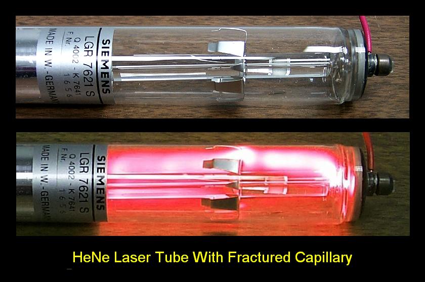
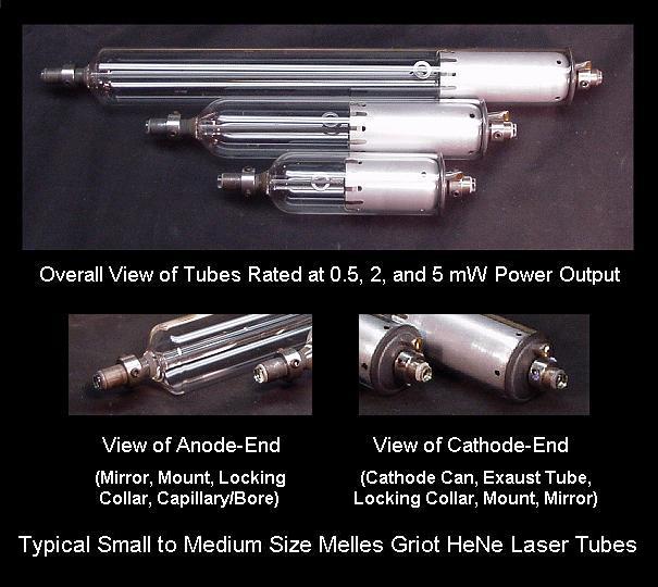
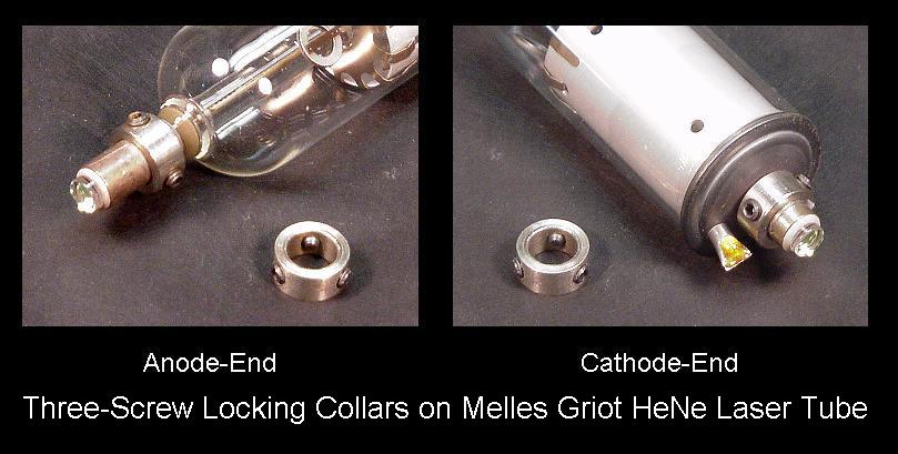
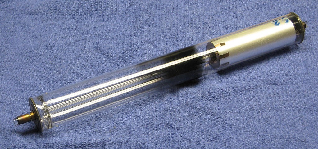
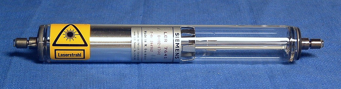
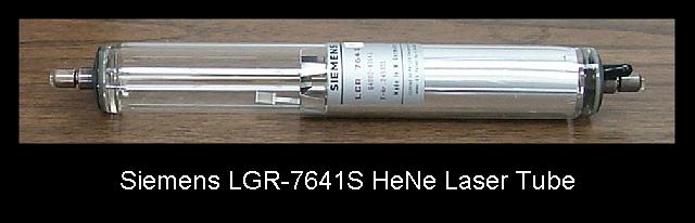
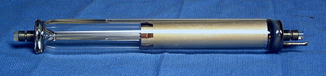
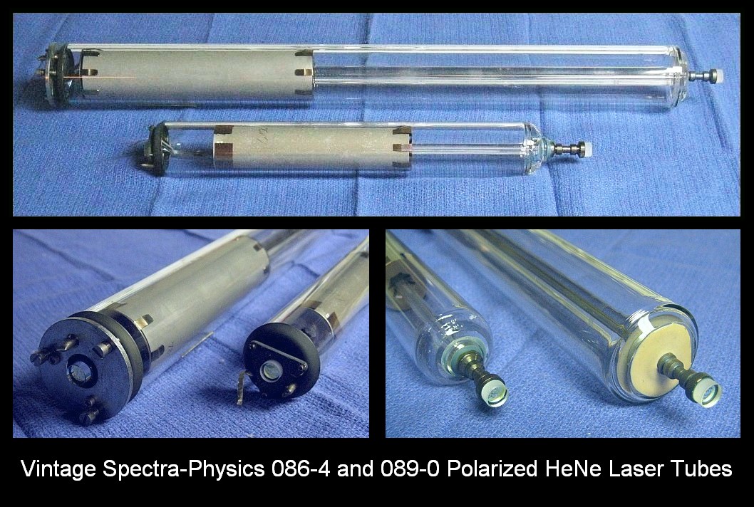
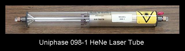
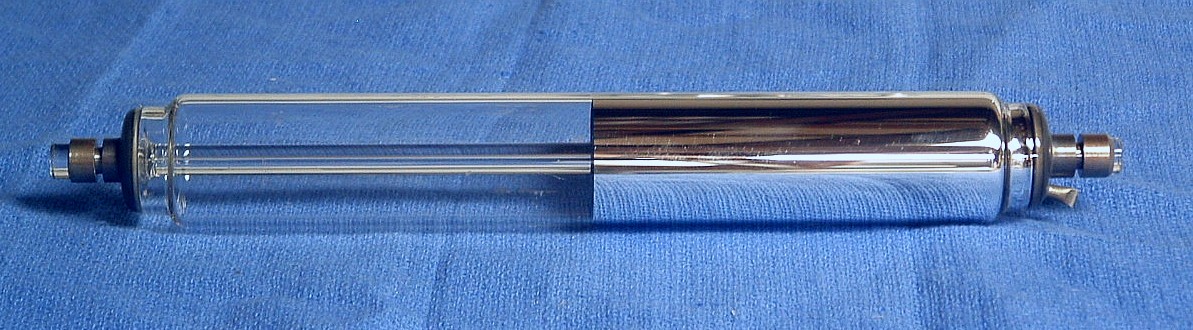
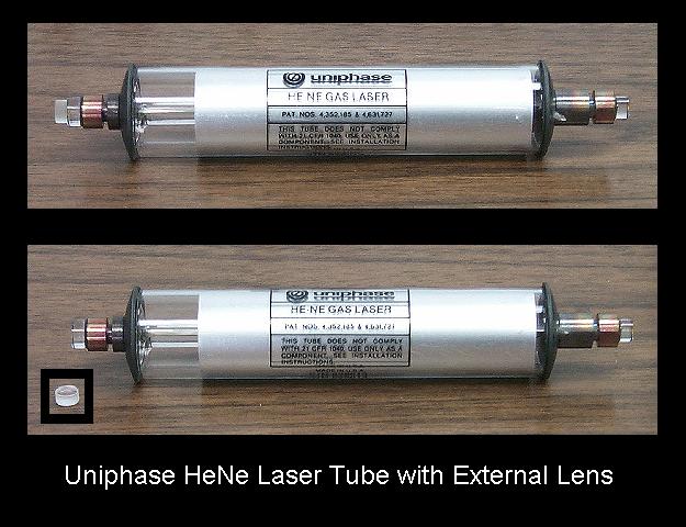
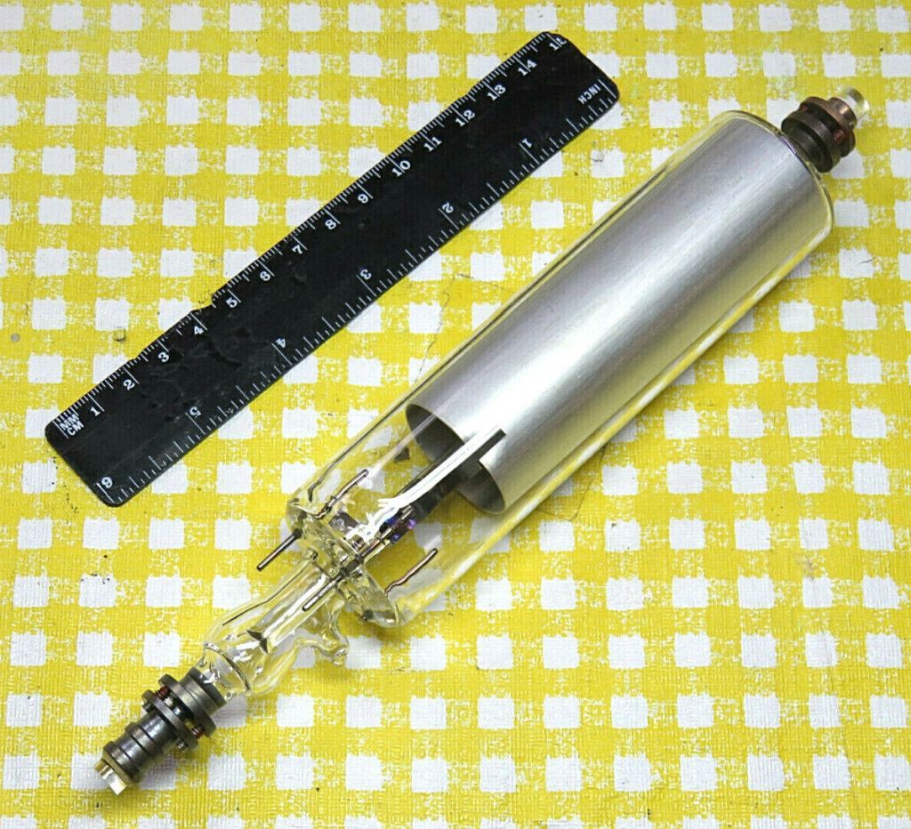
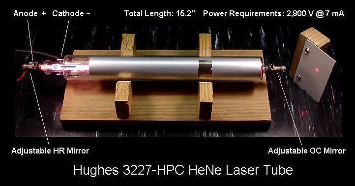
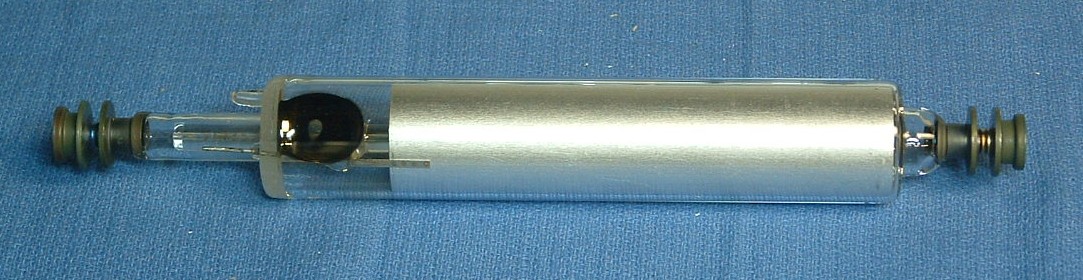
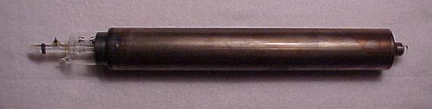
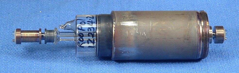
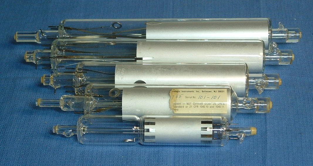
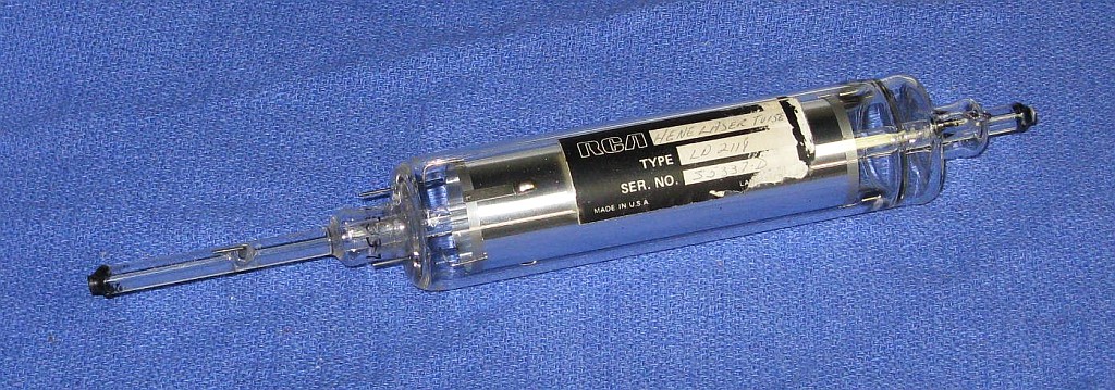
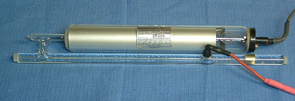
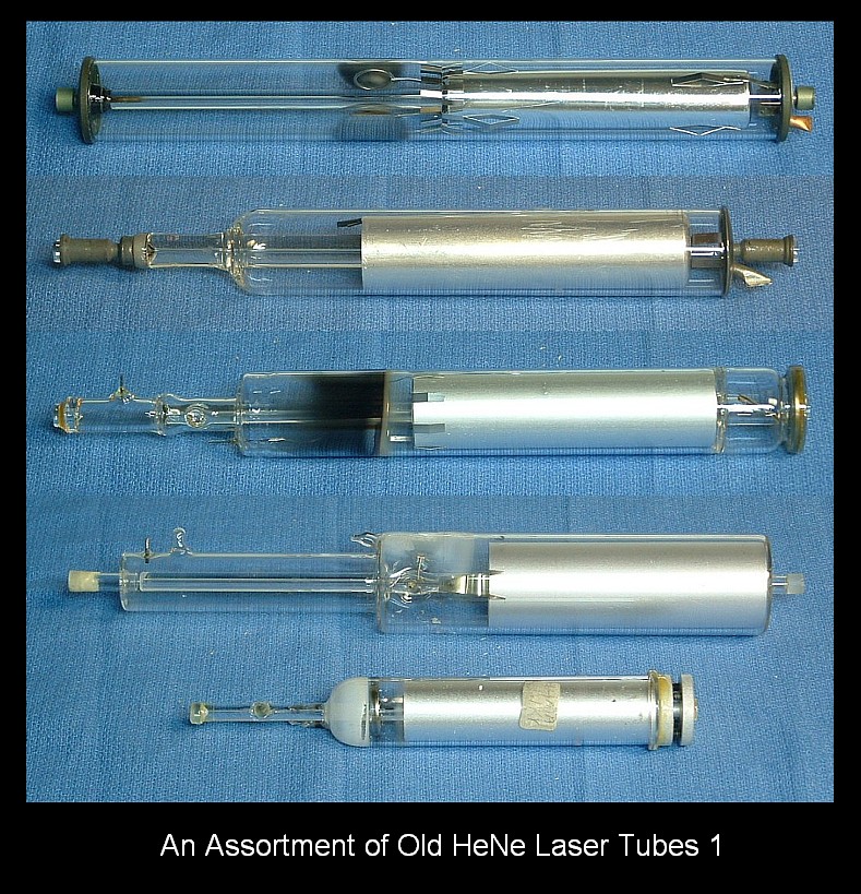
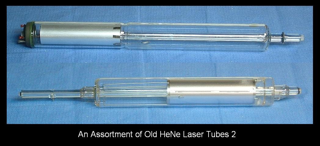
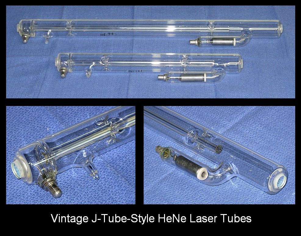
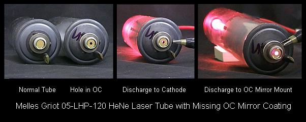
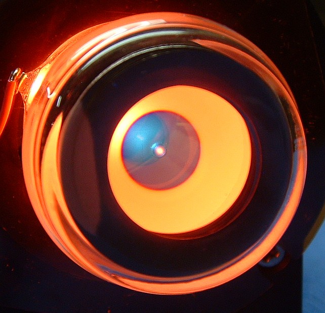
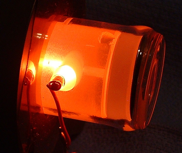
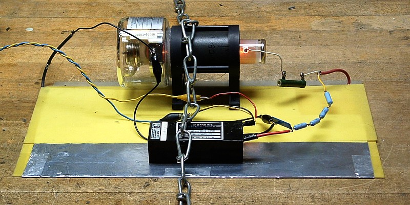
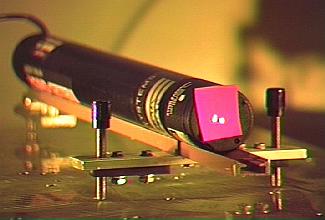
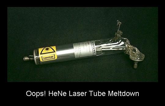
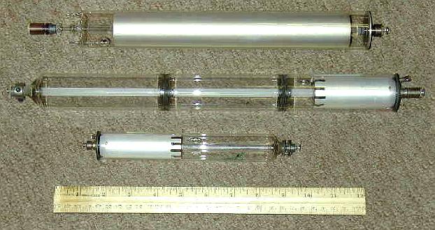
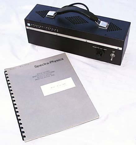
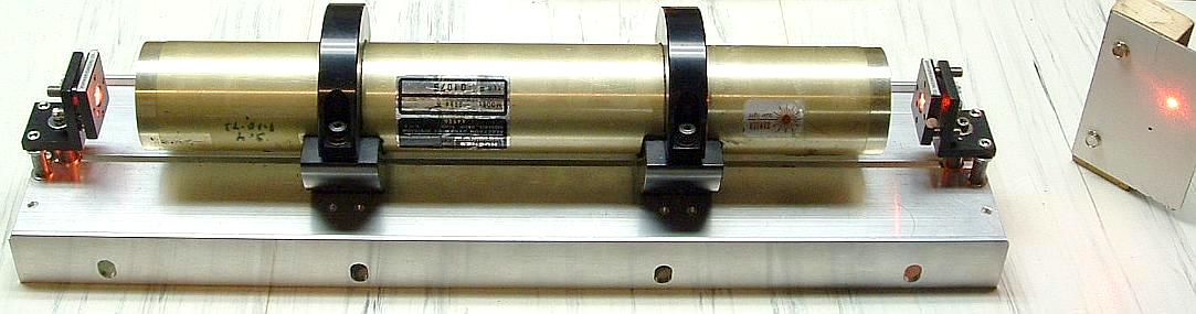
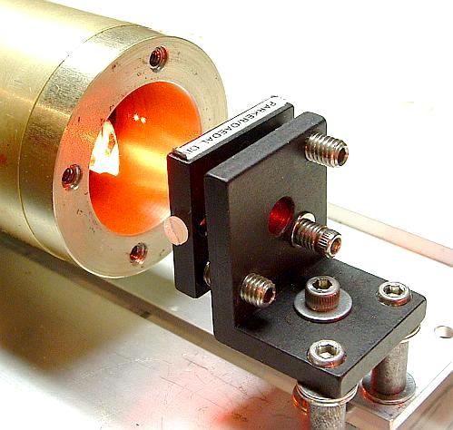
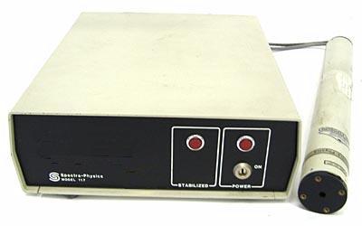
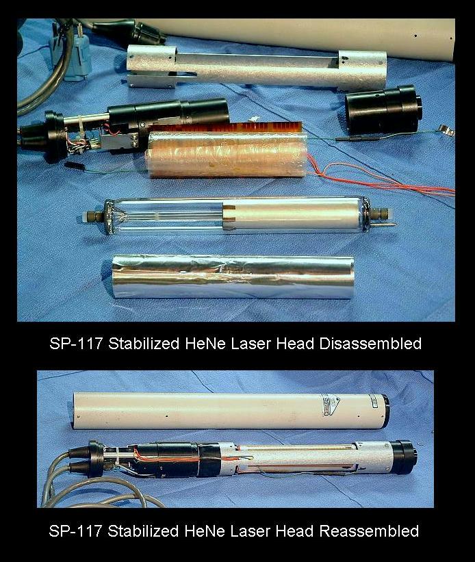
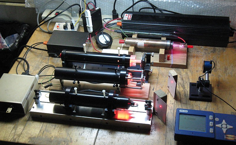
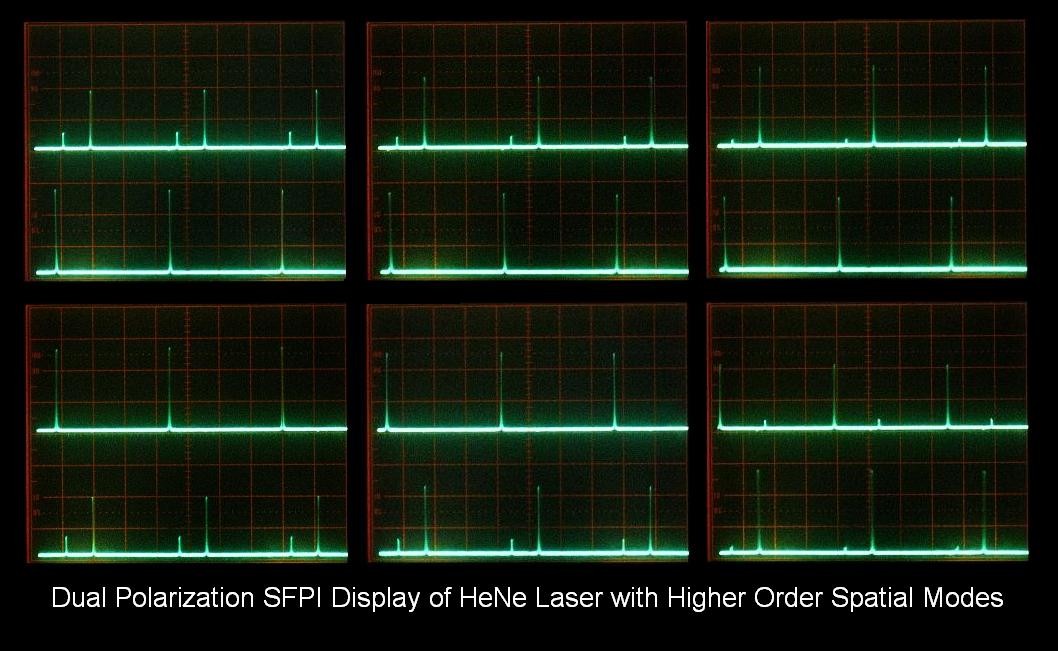
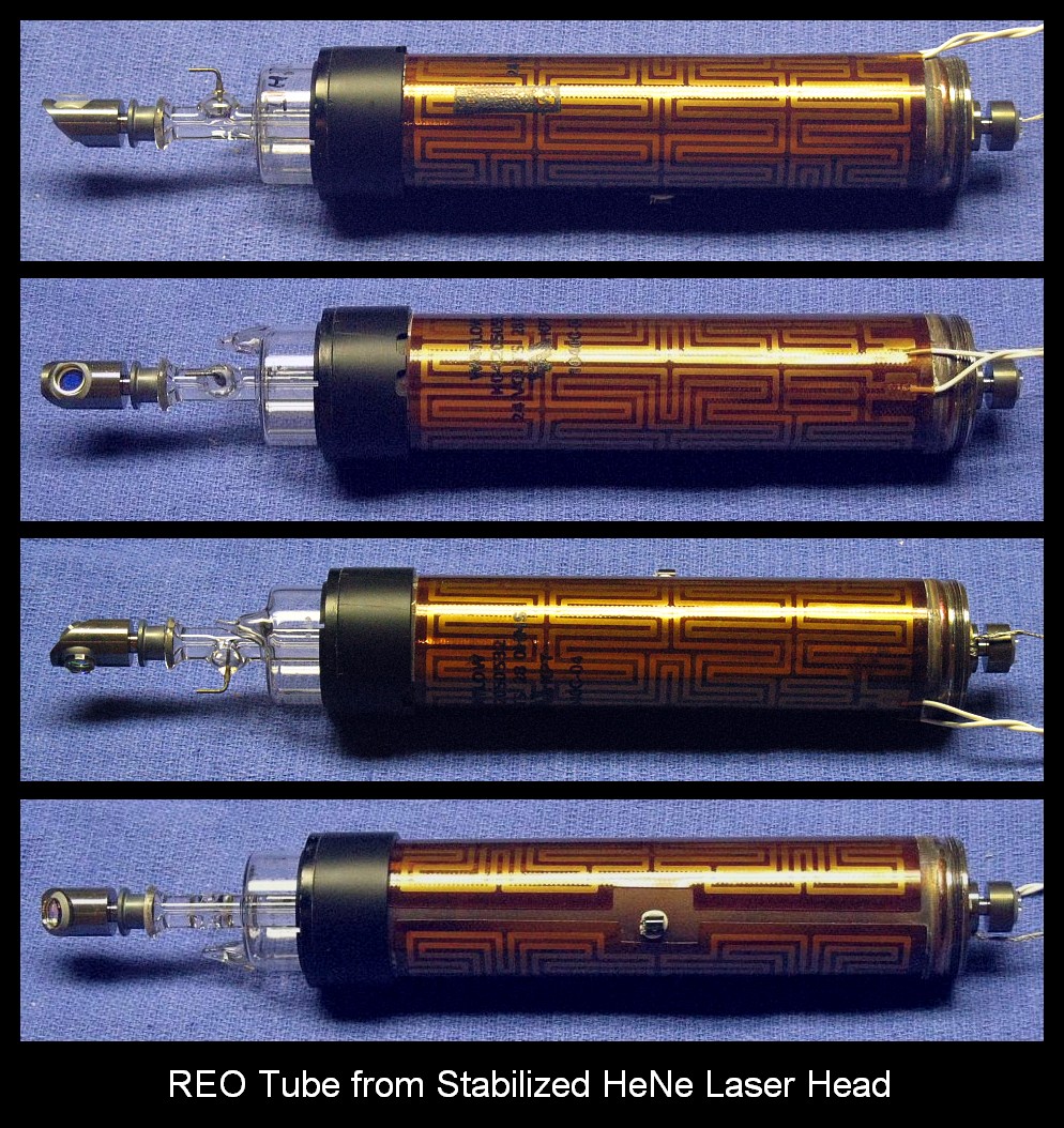
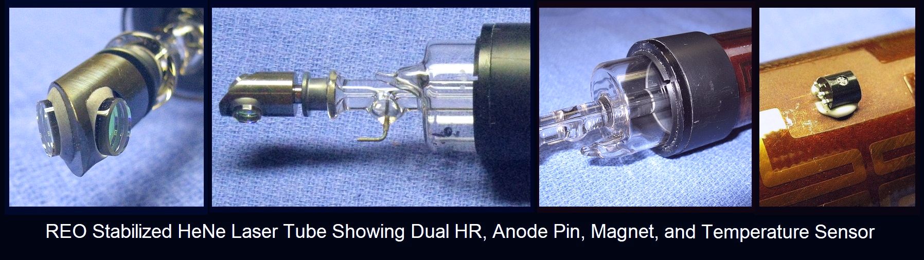
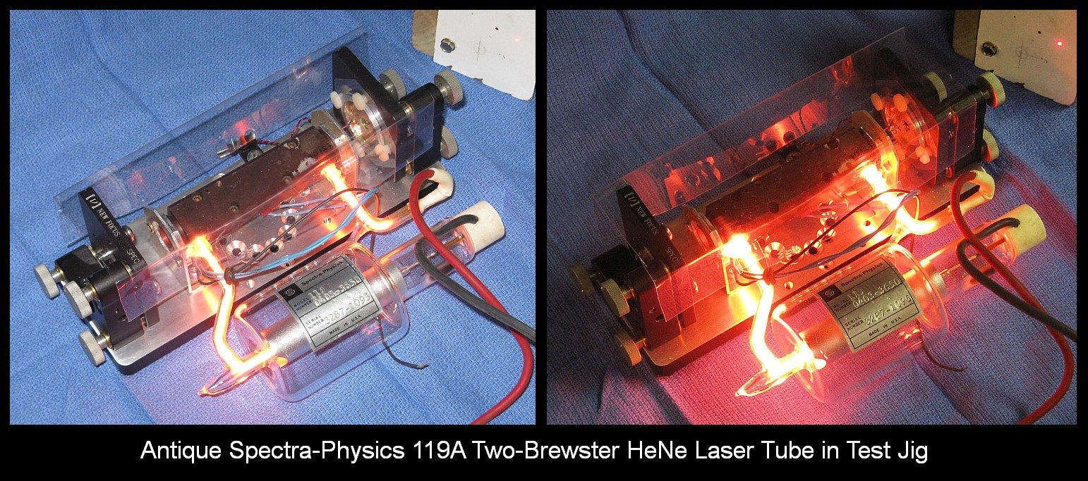