Topics not covered here may often be found in the chapters on specific lasers. For example, information on mode structure and coherence length is in the chapter: Helium-Neon Lasers, specifically the sections starting with: Longitudinal Modes of Operation.
Note that throughout this document, I use the term 'dielectric' in reference to most laser mirrors but may use the term 'dichroic' or 'dichro' for mirrors or prisms designed to separate wavelengths. Nowadays, it appears as though the term 'dielectric' is more popular.
Note that unless the laser is pure single frequency (requiring a single longitudinal mode and a single spatial mode), it will NOT be CW in the strictest sense of the term. At frequencies order of c/2L (where c is the speed of light and L is the optical cavity length) - typically 100s of MHz or higher for common lasers - the output amplitude or power won't be constant but will depend on the instantaneous sum of the individual modes. However, as a practical matter, these lasers are generally still considered to be CW.
A few on-line references with just a bit more extensive information can be found at:
And, of course, general on-line encyclopedias like Wikipedia.com.
   Name   Symbol   Factor
 ---------------------------
   yocto    y       10-24
   zepto    z       10-21
   atto     a       10-18
   femto    f       10-15
   pico     p       10-12
   nano     n       10-9
   micro    µ       10-6
   milli    m       10-3
   centi    c       10-2
   deci     d       10-1
   deka     da      101
   hecto    h       102
   kilo     k       103
   mega     M       106
   giga     G       109
   tera     T       1012
   peta     P       1015
   exa      E       1018
   zetta    Z       1021
   yotta    Y       1024
They make a big deal out of the special case of kilogram which is the only SI unit with a prefix as part of its name and thus cannot be used with an additional prefix. So, the SI police will come get you if you write something like mkg to mean a gram. :)
(Portions from: Dr. Mark W. Lund (mlund@moxtek.com).)
Put another way, Candelas are a measure of luminous intensity through an imaginary sphere with the light source at its center. For an isotropic point source 1 Candela is equal to 1 lumen per steradian. There are 4 x pi or about 12.6 steradians in a complete sphere around the source. A 12.6 lumen isotropic source would then produce 1 Candela. This doesn't really apply to your typical laser but would be a close approximation to a something like a short-arc xenon lamp. However, it is still possible to define the Candela over a portion of a diverging beam. So, if your laser put out 1 lumen over only .1 steradians, its intensity in Candelas would be 10 Candelas.
I (Mark) was at one time a true expert on photometry and radiometry and I still can't figure out how to compare one LED with another because every company specifies their parts in different ways, not all of which are appropriate. :)
Warren Smith gives an admirable discussion of photometry in his book "Modern Optical Engineering".
Or, check out the Lighting Design and Simulation Glossary for definitions of these and other related terms.
A Radiometry versus. Photometry FAQ by: James M. Palmer (jpalmer@azstarnet.com) is in the final stages of development (to the extent that FAQs are ever fully developed!). (PDF Version also available.)
(From: Ian Ashdown (byheart@direct.ca).)
A foot-candle is a unit of illuminance, which is defined in ANSI/IES RP-16-1996 (Nomenclature and Definitions for Illuminating Engineering), from Illuminating Engineering Society of North America as "The areal density of the luminous flux incident at a point on a surface."
In plain English, illuminance is the quantity of light arriving at a point on a real or imaginary surface. (The point does not have to be located on a physical surface.)
One foot-candle is equivalent to one lumen per square foot (where a lumen is a measure of the luminous flux, or quantity of light).
A wax candle flame has a luminous intensity (or equivalently, candlepower) of approximately one candela. If you hold the candle one foot away from a surface, the illuminance of the surface at this distance due to the light from the candle will be approximately one foot-candle. It will be 1/4 fc at two feet, 1/9 fc at three feet, and so on in accordance with the inverse square law for point light sources.
Brightness is a psychophysiological phenomenon that cannot be measured directly. The term "photometric brightness" used to refer to luminance, but is no longer in scientific or engineering use. (Let me rephrase that: it shouldn't be!)
There is an understandable but technically accurate description of photometric and radiometric terminology at Ian Ashdown's Publications.
(From: Don Klipstein (don@donklipstein.com).)
A lumen is defined as the "luminous flux" of 1/683 of a watt of monochromatic light that has a frequency of 540 Terahertz, or a wavelength of approx. 555.5 nm. One thing worth noting is that a lumen is defined secondarily, in terms of the candela (which is 1 lumen per steradian), and the candela is defined primarily (it's the "beam candlepower" of 1/683 watt per steradian of 540 THz monochromatic light.) Light of wavelengths other than 555.5 nm have a different amount of lumens per watt of radiation. The number of lumens in a watt of wavelength other than 555.5 nm is 683 times the photopic function of the wavelength in question, divided by the photopic function of 555.5 nm (which I believe is very close to but not exactly 1).
A "USA-usual" 100 watt, 120 volt, 750 hour "regular" (A19) light bulb usually produces 1710 lumens.
Lumens per watt is a measure of efficiency in converting electrical energy to light. Multiply this by the watts dissipated in the LED to get lumens. A typical red, orange, or yellow or yellow-green LED has a voltage drop around 2 volts and is getting around .04 watt at the typical "standard" current of 20 milliamps. A blue, white, or non-yellowish-green one typically has a voltage drop of 3.5 volts at 20 mA and gets .07 watt at 20 mA.
A candela is a lumen per steradian, or "beam candlepower". (Actually, as mentioned above, the candela is a primarily defined metric unit, while the lumen is defined in terms of the candela.) So lumens are candelas times the beam coverage in steradians. Candelas are lumens divided by the beam coverage in steradians. Ideally, that is - assuming that all light is within the beam and the "candlepower" is constant within this beam.
So you may now be wondering what a steradian is. It is 1 / (4 * pi) of a whole sphere or 1 / (2 * π) of a hemisphere or about 3283 "square degrees". To get steradians from the beam angle:
Steradians = 2 * π * (1 - cos(0.5 * (beam angle)))
(NOTE: There are a few other expressions equal to this. Proving that is homework for 12th graders taking trig / "elementary functions".)
So if you determine the steradian beam coverage and multiply that by the candela figure (or 1/1000 of the millicandela figure), you get the lumen light output - very roughly! The beam is not uniform and it does not contain all of the light. Obtaining lumens from beam angle and candela can easily be in the +100 / - 50 percent range. Actual lumens are generally higher than predicted by this formula with smaller beam angles of 8 degrees or less since the nominal beam does not include a secondary "ring-shaped" "beam" that usually surrounds the main one. Also note that some beam angle figures are optimistic and could lead one to expect a lot more lumen light output than actually occurs.
(This info is also available on my Web site at: Converting/comparing lumens, candelas, millicandelas.)
But, what about a laser? Just about any HeNe laser beam can be focused to a microscopic point which your average moron can see is more intense than the discharge inside the bore. :)
I wonder if this is getting into a philosophical question of sorts: Where is the source in a laser? For an incandescent object like the Sun, it is its surface and the radiance law applies. However, there is no similar physical surface in a laser - the beam appears to originate from the lasing medium at a point in space somewhere behind or at the beam waist but there may not actually be anything there! The wavefront curvature implies a source which for a "well behaved laser" :) like a HeNe, is very nearly a diffraction limited point, thus the ability to apparently increase the brightness compared to what is inside the tube's bore.
For "poorly behaved lasers" like those annoying high power laser diodes or laser diode bars, the fast axis is diffraction limited and effectively a point source so it can be focused to a diffraction limited point (or actually a line in this case). The effective source location is inside the laser diode chip but isn't a singularity - it is spread throughout the gain region as with a HeNe laser.
But the slow axis is multimode and options with imaging optics are extremely limited - though squeezing the 1 cm output of a laser diode bar to a couple of mm with usable divergence isn't impossible (there is an example in "Solid State Laser Engineering" by Koechner, fifth edition, and in this case, the refraction at the surface of the laser crystal helps to limit divergence somewhat as well). The benefits of it being a laser don't help since it looks more like a multitude of sources side-by-side. Each one can be focused to a diffraction limited spot but the entire collection can't be squeezed together without the divergence becoming excessive. The usual solutions to produce sub-mm size spots involve either fiber bundles or lens ducts (light pipes) which don't need to obey that law - or the law of low cost options for real people either. :)
                                          1,240 nm
                     E = 1.602*10-19 J * -----------
                                             λ
Where:
Then, photon flux = P/E where P is the beam power.
For example, a 1 mW, 620 nm source will produce about:
                    1*10-3
              ------------------- = 3*1015 photons/second.
               1.60210*10-19 * 2
For simplicity, let's assume that we are comparing a xenon HID lamp and a mixed-gas (argon/krypton) white light ion laser. Some issues:
Another way of looking at it (no pun....) would be to determine the efficiency of your source in converting electrical watts to light watts.
As an approximation, a 100 W incandescent lamp produces about 1700 lumens or perhaps 6 W of light. So, if you could manage to collect most of it and collimate it very well you would have the equivalent of a 5 W mixed gas laser in terms of intensity. However, to do this would require a combination of non-imaging optics and fiber optic bundles to collect the light, and then conventional optics to focus and direct it. With a short arc discharge lamp, you could get closer to decent collimation with simpler optics but never anything like a laser!
See the section: Radiometry Primer: What is Lumen, Lux, Nit, Candela?
(From Don Klipstein (don@donklipstein.com).)
Lumens out of a xenon lamp per watt into it? I hear enough figures of 40 for this, optimistically 50 according to various sources. But xenon lamps have electrode and thermal conduction losses, and a majority of what actually does get radiated is UV and IR including some strong near-IR lines around 820 to 1,000 nm. One watt of the visible spectrum output (400 to 700 nm) of a xenon lamp has about 250 lumens, assuming this approximates a 5600 Kelvin blackbody.
Lumens in a watt of pure broadband visible light? Equal energy per nm band from 400 to 700 nm has about 242 lumens per watt. The 400 to 700 nm region of the spectrum of a 3900 Kelvin blackbody has about 262.6 lumens per watt. If you use single wavelengths or specific bands in the mid-blue, yellowish green, and orangish red you can get about 400 lumens per watt of white light.
As for lumens per watt in a 3-line white laser beam? Lumens in 5 watts of such? Depends on what wavelengths and amount of each and whether the mixture you desire or achieve is something you call white. This could be anywhere from 120 to 360 lumens per watt using the usual argon and krypton laser lines.
For the 30 W multiline mixed gas ion laser discussed in the section: More Comments on Argon/Krypton Spectral Lines, the results of combining the contributions of all the wavelengths listed was 238 lumens per watt.
At 250 lumens per watt, a 5 watt beam would have 1,250 lumens, or slightly more light than a typical 75 watt light bulb produces. Using 150 lumens per watt, the total of 750 lumens is less than the output of a 60 W light bulb. With the optimistic figure of 360 lumens per watt, you would get 1800 lumens which is slightly more light than from a typical 100 watt light bulb.
The bottom line: If you just want lumens, a laser isn't a good choice. :-)
(From: Dane (zanekurz@sansnetcom.com).)
One way to estimate this is to use one rule of thumb for the magnitude of a star that a well dark adapted eye (scotopic vision) can see in a very dark sky. That would be a 6th magnitude star. (Some people claim better than this and some worse.)
The irradiance of a 1st magnitude star is about 8*10-11 lumens/cm2 at the top of the atmosphere. Since the lumens per watt for scotopic vision is about 1,000 at 0.5 um, this is about 8*10-14 watts/cm2. A 6th magnitude star is about 100 times dimmer than a 1st magnitude star, so its irradiance is about 8*10-16 watts/cm2 (!!!).
Amazing! This is on the order of 2,500 photons per cm2 per second or perhaps 750 photons per second into the eye and about 25 photons over a 1/30 second integration period. This checks well with the common statement in many books that only a few photons from a point source are necessary for detection.
There's at least one thing which would make these numbers not too accurate for looking at the magnitude for 1 photon (but it errs on the high side). I used the lumens per watt (about 1,000) for a monochromatic laser wavelength of 0.53 um, which is near the eye's sensitivity peak. Since the light from a star is similar to a solar spectrum, the number of lumens per watt for the extended spectrum would be significantly less and the number of photons from the star would need to be considerably higher than a laser at the visibility threshold.
(From: Anthony Cook (a.l.cook@larc.nasa.gov).)
This question was intriguing to me so I performed a quick experiment with a red HeNe laser in my spare time:
With all lights out in the lab, I sent a red HeNe laser through an 18 mm focal length aspheric lens. This produced a beam divergent with about 4 to 5 degrees full angle. Put both discreet and variable ND filters in the beam path. Went out to where the beam was 30 cm in diameter and then attenuated the beam until the source spot was just barely visible to the eye. Measured the attenuated power at the source. Here are the results:
Note: This assumes an even distribution of power. However, the beam is Gaussian, so the when viewing the center of the beam, this number will be slightly higher. Maybe someone else can calculate the exact value of the power density in the center of the beam, considering the gaussian nature of the beam).
(From: OpticsNotes.Com (bruce_nichols@my-deja.com).)
Were you dark adapted? You may be able to go lower if you wait five minutes or so. You can go even lower if you use averted vision after your eyes are allowed a longer period of dark-adaptation. Your fovea improves with dark adaption, but 10 degrees from your fovea has a significant improvement (up to 1,000 times lower threshold). Averted vision dark adaptation takes about 10 minutes, and continues to improve to 30 minutes or more. Deep sky object gazers use this trick. To see a faint object, you look just to the side of it. It's pretty cool.
(From: Anthony.)
Good point. I was definitely not dark adapted. Neither did I have my glasses on (I'm not terribly bad of sight, but my glasses help me see things at a distance a bit better).
After reading the other posts, along with some other notes and refs at Can a Human See a Single Photon?, I now see that I could have achieved greater sensitivities with my crude experiment.
(From: Leonard Migliore (lm@laserk.com).)
Central irradiance for a TEM00 beam is twice the average irradiance based on total power divided by the area of the 1/e2 diameter. So, you were picking up 8.5 pW/cm2. That ain't much beam.
(From: Hao Fong (fonghao@polymer.uakron.edu).)
To estimate the beam profile, slide a knife edge into the beam, to reduce its power on a power meter. First reduce the initial power by 13%, then to 82% of initial power. You have just found the edges of the peak part of the Gaussian distribution where most of the power is. By watching your spot in the distance when you do this, you can see what parts of it to mask off to get a reasonably uniform spot afterwards.
BTW, many HeNe lasers with multiple modes going produce more of a top-hat distribution. You may need a tube longer then say 12 cm (which only supports two modes). I haven't tried this, but it should work.
Note that measuring the output voltage of the green or yellow LED with a multimeter will be inaccurate if your laser is pulsed or quasi-CW as it will read the average voltage which may be much lower than the forward voltage drop of the red LED. The peak power output of the LED will be proportional to the peak power of the incident laser beam. Thus, a pulsed laser is more likely to work here than a CW one. Your mileage may vary.
The principle behind this stunt is that the green or yellow LED acts like a solar cell (or should we say "laser cell") for the laser and generates an output which is a function of the incident optical power and its band-gap voltage. Shorter wavelength LEDs should be able to power longer wavelength LEDs but not the other way around (unless two are wired in series with two lasers used for optical input). Thus, it should be possible to power an IR LED from a red LED and HeNe laser but that would be so boring.
Don't expect rigs like this to be used an alternative power sources any time soon. The efficiency is less than a whopping 0.001 percent (electrical power of 0.5 W into the green DPSS laser for 1 microwatt or less optical output power from the red LED). :)
(From: Leonard Migliore (lm@laserk.com).)
It depends on the laser's power and also how tightly the beam is focused. From Hecht's Optics, the radiation pressure for an irradiance S is S/c where c is the speed of light. If I got the units right, an irradiance of 106 W/cm2 has a pressure of 33 Pa.
You need to focus a kW of power into a 360 micron spot to get this irradiance; the light pressure is the last thing you need to worry about.
(From: DeVon Griffin (DeVon.Griffin@lerc.nasa.gov).)
For laser tweezers with a focused laser beam, it is on the order of a few tens of picoNewtons.
You can get a rough idea of the intensity distribution by just looking at the laser beam projected on a screen or piece of white cardboard. However, unless it is a very low power laser, its brightness will have to be cut way down to be able to make anything out. To get more quantitative information, projecting the attenuated beam onto a cheap CCD camera with its lens removed will give you an image which can be viewed safely or digitized for analysis. The only problem I've found with this approach is that since the $50 CCD cameras have a sensitivity that can't be controlled manually (automatic level control), they may get confused by the small laser spot.
(From: Leonard Migliore (lm@laserk.com).)
This is, in fact, a pretty good way of looking at laser beams. Spiracon, Inc. and Coherent, Inc. make some neat software to process these images and generate 3-D mode images on your computer. I've never looked at the raw image, but I guess you can tell if the beam is round or if it has hot spots.
The sensitivity depends on the wavelength. CCD sensitivity drops like a rock past 1 micron, but if there's one thing lasers are good for, it's putting out a lot of light. The peak sensitivity (in the visible) is (for saturation) is about 0.2 to 1.0 microwatts/cm2 at visible wavelengths. You would need about 100 times that at 1,064 nm, but that's still not much. For pulsed Nd:YAG, you will saturate a CCD with 10 nJ/cm2.
For even small lasers, you'll likely need to cut the beam intensity way down with neutral density filters or other means. For a laser with a peak irradiance of 30 mW/cm2, you'll need to cut the beam down 3,000,000 times, which is a density of 4.4. You may want to use a reflective 4.0 filter with an absorptive 0.4 behind it. If the laser operates at a near-IR wavelength, the CCD will be much less sensitive as noted above so less filtering will be needed.
(From: Thomas R. Nelson (tnelson@uic.edu).)
I've done this at 745 nm, to look at both a 400 mW (average power) beam, and an amplified beam (peak power approximately 10 GW!). I would recommend using window reflections to attenuate, rather than any transmissive attenuators. For high power beams, thermal blooming in a ND can distort the beam, and at any power level, the slightest blemish or spec of dust on one of the filters can show up. Chances are you'd need to take only one or two reflections at most to avoid saturating the CCD. Once you have the image file, you can use a variety of graphics packages to look at the profile. You don't necessarily need to buy some special package for looking at laser beams.
(From: Paul Pax (phpax@azstarnet.com).)
We've gotten a Kodak DVC323 for exactly that purpose. Popped the lens off and sent the beam right to the chip (through about ND 5, for ~20 mW at 532 nm). Works fine for qualitative measurements, and even reasonably well for quantitative ones, if you watch out to get in a linear regime. Kodak says there is significant processing in the camera itself, and that the resulting image is not linear. By the way, Kodak makes the software controls for the camera available on its web site (VisualC and VisualBasic). I've written a basic beam analysis program with it.
(From: Johnathan Leppert (service@qth.net).)
Get a USB camera, like the one which is used often and is very popular with the amateur astronomer crowd. There is a certain camera (think it's a Panasonic) which has a lens which can be screwed off, revealing the CCD. This camera is around $50 to $125.
Then download the Spiracon, Inc. demo software.
All you need to do is have the beam centered on the CCD, and you can get a complete real-time beam profile (which includes a wealth of data including your spot size (FWHM) minus the $2,000 bloat of a professional beam analyzer, which is good for most applications (CCD USB webcam resolution about 500 to 600 lines, plenty for high resolution profiles).
Beams of light do not interact in a linear medium like a vacuum, or air or glass at reasonable power densities). So, even at the intersection, only the original frequencies/wavelengths are present unless the power density is so high that the physical medium behaves non-linearly (but never in a perfect vacuum).
However, if the beams are both incident in the same location (and some polarization overlap) on a photodiode (a non-linear device having a square-law response) with sufficient bandwidth, the difference frequency between them will be seen. (The sum frequency is also produced but no know photodiode will respond that fast.) However, these frequencies do not really exist in the spectrum of the light beams until they have been detected by the photodiode.
In a non-linear medium like LiNbO3 or KTP, or optical fiber and many other materials at high enough power , there can be new frequencies generated including the sum, difference, doubling of either of the original frequencies, or other combinations.
So, no light sabers, but many other even stranger phenomena.
And photographing the beam scatter of even a high power laser from the side, even *almost* head-on is generally safe as long as the actual beam doesn't enter any of the optics (including our eyes!). Add some dust, smoke, or fog to make it stand out.
But, you've seen those photos apparently shot directly into a laser beam. My recommendation is to NOT try to reproduce them with a digital camera unless you won't mind ruining it. The CCD or CMOS sensor is the heart of your camera. Any damage to even a small number of sensor elements (pixels) will render the camera useless for most purposes.
A direct hit from a laser of less than 1 mW may damage the sensor since it can focus to a micron-size spot there. Using a fast shutter speed won't necessarily help since digital cameras don't have real shutters - the sensor is always exposed and a narrow laser beam may get through even a stopped down aperture in its entirety. Some guidelines:
Film cameras aren't as susceptible to damage from the laser beam but limiting the power to 1 mW is still a good idea.
WARNING: If your camera has an optical viewfinder, take special care that your vision isn't damaged should the beam enter it directly!
Unfortunately, low power laser beams don't look like Star Wars light sabers so some assistance is needed to make decent photographs.
(From: Joe Smiley (cadcoke3@yahoo.com).)
One technique to help catch the beam is to use two exposures, and combine them in something like Photoshop. One of the exposures, is done in complete darkness (except for the laser) and is timed to capture the beam itself, and the glow it has on the surrounding areas. Then, the next is done is subdued light (you can still have the laser on) to get the surroundings.
Another approach (which I've never tried) is to use a flash and an exposure time longer than the 1/60 second the flash requires. The flash itself will occur as soon as the shutter opens, but the longer exposure time will keep the shutter open after that and allow the light from the laser beam to accumulate.
Of course, if you want to see the beam, you must have something in the air to catch the beam, like smoke or dust.
If it is the intense light where the beam is hitting, I've not tried that. But, I figure the double exposure idea could be used there as well. However, in this case, the exposure for the laser is fast with a small aperture. Then the laser is turned off, and a second pictured done to catch the surrounding areas.
Here and elsewhere, the intracavity photon flux may also be referred to as "circulating power" or "intracavity power" and is measured in watts. However, the only way to actually tap into it would be to redirect the intracavity beam out of the laser with a super fast optical switch and then, the power would only be available for a duration of at most the time for 1 round trip between the mirrors. This is one reason why there can be a higher photon flux inside the cavity than there is input power to the laser. For example, a 100 mW diode pumped solid state laser typically uses less than 1 W of pump power to excite the lasing crystal. With 98% reflectivity OC mirror, the intracavity power will be 5 W. No, lasers are not free energy devices but they are energy storage devices. :)
The analogy comparing an electrical tuned circuit to a laser resonator is often used but isn't perfect. In a tuned circuit, the voltage and current inside can indeed be many times that of the driving source, by the ratio of the Q factor of the circuit. However, the true or real power is very low since the voltage and current are largely out of phase. As with the laser, the power can be extracted only by somehow diverting the energy into a load where it becomes true power and then only for a short time.
Also see the sections starting with: Gain, Stability, Efficiency, Life, FB versus DFB Laser.
There are several ways to design a device that will determine the power in a beam of light. Here are two:
Silicon PIN photodiodes all tend to have about the same spectral response curve unless they are specially processed or have a filter added to the detector assembly. They peak around 900 nm at about 0.4 to 0.6 A/W. At visible red expect around 0.3 to 0.4 A/W. See Typical Silicon Photodiode Spectral Response.
For all of these approaches, changes in beam diameter (with distance) or its position should not make much difference in readings as long as the entire beam falls on the sensor. However, if the surfaces are not AR coated (which is quite likely with the salvaged sensor in a home-built power meter), angle with respect to the beam will affect the reading by several percent or more due to the varying reflectivity. The sensitivity increases as the Brewster angle is approached for the portion of the light with the appropriate polarization orientation. The reflectivity of randomly polarized light also varies slightly with angle. Thus, it is important to have the sensor perpendicular to the input beam if possible. In addition, for non-AR coated sensors, the response may be much lower than expected (as much as 20 percent or more) due to reflections at several surfaces requiring increased gain or conversion factor to get accurate readings.
Here are some comments on these approaches:
(From: Jonathan E. Hardis (jhardis@tcs.wap.org).)
Here are a few effects that may not have been considered for photodiode based detectors:
Both of these methods are well documented in the technical literature.
(From: Bill Sloman (sloman@sci.kun.nl).)
The important thing to note is that a photodiode actually detects photons, not power. Up to about 850 nm, each photon actually reaching the diode junction generates one pair of charge carriers. A 425 nm photon, carrying twice the energy of an 850 nm photon generates the same pair of charge carriers, so the same current represents the absorption of twice the power.
Since the 425 nm photon has rather less chance than the 850 nm photon of actually surviving the trip down to the diode junction, so the actual ratio is closer to 2.5:1.
Above 850 nm, the photons haven't got quite enough energy to separate a pair of charge carriers, and can only separate those that are already somewhat excited. The proportion that are sufficiently excited depends on temperature. A electric field also helps, so biasing the diode increases it sensitivity to long wavelength photons. As the wavelength rises above 850nm the extra energy required to separate the charge carriers also rises, so the proportion of 'sufficiently excited' carriers declines quite rapidly.
In principle one could build a wavelength correction into the power meter, but you would need to add a wavelength sensor to the power meter to make it a useful feature.
The Centronics data book gives a typical spectral response for the 5T series diodes, which effectively gives you the inverse of the wavelength correction function, albeit with rather low precision.
The alternative approach is to use a sensor which responds to the heating effect of the laser beam. These exist, but what you win on wavelength independent calibration, you lose on sensitivity and zero stability - in effect you have built a thermometer to measure the heating effect of your laser beam on a more or less thermally insulated target. Unless someone has done something very neat in this line, it doesn't strike me as a practical proposition for your application, granting your limited budget.
(From: Mike Hancock (mhancock@utmb.edu).)
Sharp describes a power meter in their "Laser Diode Uuser's Manual". It uses a Sharp SPD102 reverse biased. They claim +/- 15% accuracy. The SPD102 has a flat response and their peak sensitivity matches the wavelength of "laser diodes", (whatever that means --- sam).
(From: A. E. Siegman (siegman@stanford.edu).)
Many simple low-cost large-area silicon PIN photodiodes (e.g., several mm to a cm in diameter) will have close to unity quantum efficiency, (meaning close to one electron out for one photon in) across much of the visible range and out to close to 1 micron. The manufacturer may also supply a curve showing how the actual quantum efficiency varies with wavelength.
This quantum efficiency doesn't vary much with the reverse bias that's applied over the normal range of operation, or with temperature, and these photodiodes are also fairly rugged devices whose properties tend to be fairly stable with time and use or abuse.
So, if you allow for the varying energy of a photon with wavelength and the manufacturer's claimed variation of quantum efficiency with wavelength, you can make a simple. rugged, large-area, auto-calibrated, and fairly accurate power meter using just one of these diodes, a small battery, and some simple electronics to measure the DC current from the photodiode.
Data on these diodes can be found on the web, and building a power meter like this should be a simple and interesting exercise for one of your electronically talented students.
Source: Handbook of Modern Electronics and Electrical Engineering, C. Belove, ed., John Wiley and Sons, second edition, 1986, pp. 433-434.
pn photodiode: Photons with an energy greater than the band-gap falling generates electrons in the p-type region and holes in the n-type region. If these are within the diffusion length of the junction, they move toward it and are swept across by the field. Light falling in the junction region generates electron-hole pairs which are separated by the field. In both cases, electron charge is contributed to the external circuit. The pn photodiode may be operated with reverse bias and then acts as a current source. They may be operated with no bias and will then generate a voltage and current (photovoltaic effect) with the p-type material being the positive terminal.
pin photodiode: The carriers generated in the junction region experience the highest field and get separated most rapidly and provide the fastest response. The pin photodiode has an intermediate thick intrinsic layer. This is where it is designed to absorb light thus minimizing the effects of the contributions of the slower p and n regions.
Avalanche photodiode: If the reverse bias on a photodiode is set close to the its breakdown voltage, carriers will be accelerated in the depletion region and will have enough energy to excite other electrons into the conduction band resulting in a multiplication effect (avalanche gain). Values of 50 are typical though the gain of some devices may exceed 2,500. Avalanche photodiodes are designed to have uniform junction regions to handle the high electric fields.
Solar cell: This is basically a large area pn silicon photodiode designed to absorb broadband solar radiation.
Phototransistor: A bipolar transistor where the collector-base junction is exposed to light and takes advantage of the gain of the device.
Photo-FET: A field effect transistor where the gain region is exposed to light thus changing the gate voltage.
Sensor manufacturers often have technical information and even sample circuits in their catalogs and on their Web sites. For example, see Hammamatsu Corporation, Thorlabs, and UDT Sensors.
Some specific technical information includes:
A resistance heater may be built into these types of sensors so they can be calibrated without using a laser. The procedure is straightforward, though not quite as simple as inputting a known power (I*V) and adjusting the appropriate pot so the meter reading matches the power since there is some difference in the sensitivity/losses/whatever between light input and electrical input which is lumped into a "calibration constant" for the sensor.
I know of two basic types of thermal sensors (but there are no doubt others): Those that use what are basically Peltier devices (Thermo Electric Coolers or TECs) and those that have an array of up to 50 or more really really tiny thermocouple junctions glued to a thin heat absorber/spreader plate. The response of the latter which are often called "thermopile" sensors should be much faster since there is almost no thermal mass involved. The TEC-based sensors have a slower response but are more robust.
CAUTION: Thermopile sensors are extremely: fragile. To minimize thermal mass, the plate is made very thin and is easily broken. And, it's suspended by the superfine wires going to the thermocouple junctions glued to its rear surface and these will break almost simply by looking at them the wrong way. Even gentle pressure from a cotton swab may ruin the sensor may fracturing the plate and/or tearing the wires. Been there, done that. :( Don't be tempted to do anything beyond using compressed air or dusting the surface off with a camel's hair brush. If it's ugly from previous laser shots, so be it. Ugly is good. :)
Except for minor details, the description below is similar to the TEC-based sensors for use with the instruments described in the section: Scientech Thermal Laser Power and Energy Meters.
(From: Steve Roberts.)
If you need to measure optical power above about 50 mW, thermal becomes a good choice. Having dissected one of mine, it consisted of a 3/4" diameter adsorber disk painted with carbon black in a binder. You can get the carbon black from some drugstores as powdered charcoal for adsorbing poisons in the stomach (at least that's what the pharmacist told me it was used for). A 100 ohm length of thin nichrome wire is wound in a grove around the exterior of the absorber disk and was used as a thermal reference to calibrate the device. The adsorber disk is clamped against a Peltier element with about 100 junctions and this is attached to the outside of the sensor, which acts as a heatsink. The sensor is mounted in a black body cavity (which both adsorbs and radiates heat with high efficiency). This is made of 3" aluminum drilled to hold the sensor. The aluminum is black anodized and then coated with a black oxide coating to make it really black. Other versions I have use a water cooled block with the same Peltier type junction, which when used in reverse generates current (Seebeck Effect). The output voltage from the peltier is very low and has an offset, so this gets ran into a opamp gain stage to clean things up and run the meter movement.
A sensor of this type is relatively easy to make if you have access to a decent set of shop tools, but your calibration would be +/- 10% at best.
Here are some more details on detectors:
I've used flat black black Krylon on some pyroelectric based adsorbers as a emergency fix. No difference in reading. The black from the factory on older thermal adsorbers was sprayed on with carbon dust in it. A few cheapies I've seen have just been black anodized plate with a thick dye layer. Now it's a vacuum deposited film on the new ones. I've had great success with the finely powdered charcoal sold by drug stores as a poison control treatment, mixed with a thin but strong nitrocellulose type binder, I've used clear model airplane dope, with just a few drops of thinned binder to a large amount of powder so it doesn't gloss and keep the applied layer thin. Results have always been a small error due to coating thickness, not enough to matter with most lasers
Some of these detectors have a disk of thin black glass as the absorber It is often something like a Schott RG series, try searching for a company called "Newport industrial glass", they do small quantities. RG has also been known to act as a Q-switch for YAG.
The pyro detector I blew was rated for a 50 joule laser, a 2 joule oscillator amplifier shot with a 2 mm or so beam blew a hole deep into the detector face on the first shot, seems the manufacturer claimed you needed to spread the beam over the whole face. I was doing a freebie consult for the local hospital on their pulsed holographic ruby laser used for breast cancer research. I ordered the detector, having asked the salesman if it could take a direct shot. "Oh sure, no problem, we have a model optimized for short pulse ruby." Bang! We tried to get a refund, but they refused, so we had the credit card company stop payment on it, I ended up stuffing a little carbon in the crack and a coating of black Krylon hand painted on. you couldn't see the hit. It ended up the detector worked great with a Tektronix digital scope and so the megadollar controller went back and the damaged detector is still in use to this day. The ruby was pretty stable from trace to trace and so the subsequent shots on the repaired detector.
(From: Lostgallifreyan.)
Activated charcoal powder. Various sources: Brewers supplies (comes in sachets with wine kits for fining). Incense burners (small disks, can be ground of with a fine file). Medical suppliers (in small packs that can be swallowed to absorb poisons).
The easiest and cheapest way might be to get the address of a brewer's supplier and ask them if they're willing to send you a sachet, the stuff is ideal.
I made a black paint out of 3 parts white spirit to 1 part yacht varnish. (I'd tried matt finish aeroplane kit glue, it was useless. I couldn't get any butyl acetate as thinner, and other solvents made it coagulate). The varnish is gloss, but the high viscosity and adhesion allow a heavy loading of carbon powder (activated charcoal, politely blagged from a brewers supplier). I can't quantify the amount of powder, as it won't suspend evenly in the liquid. I treated it as if it was very wet sand, painted on the ceramic surface of the thermopile, such that vibration could make it shiny as the particles settled after painting it as flat as I could get it. I then shook it, keeping it on a plane surface, to even out the thickness and consistency. I dried it with forced air from a 12 V 80 mm fan at very close range. The forced evaporation (and the high-frequency agitation in the fan airflow) made sure the carbon could not settle in time to allow a shiny surface to develop.
The result is a deep black, almost as good as soot deposition. It looks like very fine velvet, like that paper which photographers use for extreme light absorption. It's damage threshold is high, I had to focus 158 mW to within 0.5 mm diameter before I could get any smoke out of it, and to within 0.25 mm diameter before any blanching of the surface occurred. Response time on the thermopile is good (I didn't get numbers for this though), and the accuracy is good too, about 1% down in sensitivity off- centre to edge, symmetrical around that centre. I've made a very basic gain stage with a dual op-amp (LF412), with the first half making a new ground about 2.5 V above negative so I can get accurate through-zero offset tweak, and headroom to measure up to 30 watts on a voltmeter's 32 volt range. I don't know how much the carbon coating's varnish binder might vary with wavelength, but probably very little given that it has very low reflection now, and I think this system could be good for 1% accuracy providing the beam is centred on the detector plate and spread just wide enough to be below the damage threshold.
(From: Bill.)
Almost 50 years ago, not long after the first lasers were operated, accurate laser energy measurements were very difficult to do. Usually, energy was reported to be much higher than it actually was.
With that in mind, I built a calorimeter. I consisted of a small dewar that had windows through which a laser could be shown. The inner chamber was filed with about 5 to 10 ml of water which had a few drops of india ink added. This absorbed the radiation in depth without causing surface foiling. I used a Beckmann differential thermometer to measure temperature with about a millidegree or two. Some resistors were immersed in the water. By putting in known (measured electrically) amounts of energy, the equipment was calibrated. As a check, the thermal mass could be calculated and compared to the calibration.
Similar functions could be obtained today easily. You don't really need a vacuum dewar when you can use polystyrene foam or the like. Just a glass jar might do. Instead of a precise thermometer, you might be able to use thermistors and a digital multimeter. The point is that you can get down to basics without anything truly complicated.
(From: Bill Sloman (sloman@sci.kun.nl).)
A lot depends on whether you are interested in the power averaged over the length of the pulse, or the time-resolved power within the pulse.
If you want nanosecond time resolution, you need a photo-multiplier tube (PMT) of some sort - you need lots of gain-bandwidth and the PMT is about the only way to to get it. Unfortunately the gain of a PMT depends on the 10th power (depends on the number of dynodes or whatever) of the voltage across the tube, plus a number of other less easily measurable parameters, so you need a fancy calibration scheme to let you compare your laser with a source of known brightness, which is going to involved quite a lot of predictable attenuation - in short, a can of worms.
If you just want to open a window around the time the laser is on, then a photodiode driving into a Burr-Brown OPA-655 may be enough. The photodiode output isn't as unpredictable as a photomultiplier's, but it depends on the temperature of the photodiode at the junction (which can rise significantly while the laser pulse is being absorbed - a thin junction hasn't got much thermal mass), and the wavelength of incident light, so you still end up with a calibration problem, but at least you haven't paid $1,000 for a photomultiplier before you start buying in the attenuators and so forth.
At least the calorimeter and pyro-electric approaches measure power directly. You can always use precision attenuators to reduce the power at the detector to something manageable.
The use of a Neutral Density (ND) filter is one of the most commonly used approaches but it might be hard to find an optics store open at 3 AM on a Sunday morning to buy one that you need NOW. :)
Putting several pieces of paper or frosted glass or plastic in front of the photodetector is an often used technique to cut the sensitivity. Depending on the number of layers and color, the attenuation can be varied over a wide range. However, I bet the manufacturers call it something other than "a few pieces of paper" in their bill of materials. :)
Using a partially reflecting mirror is another possibility. An Output Coupler (OC) mirror for the same type of laser being tested might have a transmission of a few percent. Just put it at a slight angle to the beam so the reflected spot goes somewhere such that it doesn't interfere with the laser or the photodetector.
At a single wavelength laser or one having a fixed output mix of wavelengths (like a multiline argon ion laser) with a power level of up to a few mW, you can also try some bits of colored glass or plastic, even if they aren't intended to be used as filters. The fact that they aren't neutral density won't matter.
However, many dyes - even those used in some supposedly neutral density filters - are photochromic - they change their absorption (up or down) depending on the power density of the light passing through them and thus become non-linear. This may show up as a drift in the power reading after the beam intensity or position on the sensor changes. Spreading the beam may reduce this effect. I have some amber glass filters that do this when the incident power at 532 nm (green) exceeded a few 10s of mW. I was using a pair of them in series as an attenuation filter for a laser power meter so that a small silicon photodiode would work up to 200 mW. It took awhile to figure out that the slowly declining reading leading to a 2 or 3 percent error at 100 mW was caused by the filters and not some obscure circuit problem. The power reading would start out at one value and then gradually go down as time progressed, finally stabilizing at a lower value. Replacing the amber glass with a piece of an ND2 neutral density filter resulted in similar behavior but in the opposite direction - the dye was becoming slightly bleached by the high intensity light and would drift upward by 1 or 2 percent over the course of a few seconds. Since laser power meters usually aren't spec'd to have an accuracy much better than +/-5 percent, such behavior really isn't that significant, just annoying. And, since this particular power meter is part of my Coherent C315M laser test jig, calibrating it to be accurate at around 100 mW results in negligible error since that's the power at which most lasers are tested and adjusted. :)
Mount any polished filters at a slight angle so reflections from their non-AR coated surfaces won't affect the laser (from back-reflections) or the reading (from multiple reflections). Always orient the meter so reflections are slightly off to one side, but close to the laser's output aperture so that the reflection losses don't change much due to angle.
Determine the calibration factor for the power meter by measuring a low laser with and without the filter in place.
Assuming your laser power meter can be used at the wavelength of your new BIG laser, it can easily be adapted to read high power as long as the polarization of the laser is fixed (see below). Send the laser beam through a pair of 45 degree plain glass beamsplitters (e.g., microscope slides) in series with the reflected beam from beamsplitter 1 going to beamsplitter 2 and sending only the reflected beam from beamsplitter 2 to your laser power meter's sensor. Each beamsplitter will reflect about 8 percent and pass 92 percent. So, after two reflections, you get about 0.64 percent. The reading on the laser power meter will then be about 0.64 percent of the true power or roughly 64 mW for a 10 W laser. It can be calibrated more accurately by using a laser of known power to test it. The laser doesn't need to be high power as long as 0.64 percent of its power can be measured with enough resolution on your laser power meter.
There are at least two advantages to this approach over that of using neutral density filters to cut down the beam intensity. The main one is that there is no problem with the beam passing through plain glass while a neutral density filter could easily be damaged by an intense beam. The other one is that the cost is negligible!
Where the polarization of the source isn't constant (e.g., it is from a randomly polarized ion laser or from a multimode fiber), it is essential that the beamsplitter be polarization insensitive. The plain glass at 45 degrees does not satisfy this requirement since its getting close to the Brewster angle. For example, using the plain glass beamsplitter with a high power laser diode fed through a multimode fiber may result in a power reading that varies by a factor of two or more by just moving the fiber as the polarizations of the various modes move and their polarizations change. Furthermore, since the distribution of power in the various modes tend to change with power, the reading may not be linear with respect to power even if the fiber isn't touched. For a random polarized HeNe laser, the power reading may change by 10:1 due to mode sweep as the tube warms up. If the angle of incidence is arranged to be close to 90 degrees (normal incidence) rather than 45 degrees, the error will be small, but this is generally difficult and may not be possible at all.
Commercial beamsplitters are also available which are relatively polarization insensitive. But many are far from perfect and a residual error of 5 to 10 percent is often present. This will depend on design and is generally somewhat wavelength dependent. The manufacturer will generally supply a plot of the s and p polarization versus wavelength.
However, a polarization-insensitive beam sampler can be made by using two identical beam reflecting plates in series oriented so that the orthogonal polarizations are reflected at the same two angles of incidence (but in opposite order). So, for example, orient the first plate at 45 degree incidence so the vertical polarization has a high reflectance while the horizontal polarization has a low reflectance. Orient the second plate so the opposite occurs for the beam reflected by the first plate. If done with care, the result will be a beam sampler that is totally independent of polarization.
The extension to even higher power or for a laser power meter with a lower maximum power rating should be obvious. :)
WARNING: Make sure that the non-reflected beams terminate in something that can take the power and not burst into flames!!! And don't forget the laser safety goggles!!!
Although the circuits in the following sections are intended for laser power meters, they can also be used to drive a PC Data Acquisition System (DAQ) or similar recording device to plot laser power fluctuations due to mode sweep or other phenomena. However, most are not optimized for response time or bandwidth.
I tossed this together using a 4 segment photodiode chip from a dead and abandoned Mouse Systems optical mouse (the old type which uses a pair of these chips - one for each axis). The active area of each segment is about 1 mm x 1.4 mm (total about 1 mm x 5.6 mm) which isn't great but is adequate to capture the entire beam of a typical collimated laser diode or HeNe laser.
But there is no need for you to use this photodiode so don't go searching the Universe for a totally obsolete dead mouse! Much better choices are available, probably already in your junk box. :) Aside from the peculiar geometry, a larger area photodiode would make things much easier and allow for lasers other than raw HeNes. To ease this a bit, I tied all 4 segments in parallel so one dimension is no problem at all. There are microscopic gaps between the segments but I estimate it to be less than 5 percent of the area so the loss should not be a big problem. But the beam still needs to be less than 1 mm or so in diameter and real beams are not sharp edged, but have more like a Gaussian distribution.
An 'instrument' (this term is being used very generously!) of this type will not replace a $1,000 commercial laser power meter but may be sufficient for many applications where relative power measurements are acceptable and/or where the user is willing to do a little more of the computation. :-) One cannot complain about the cost: $0.00. :) If you're willing to splurge, go for a $2 photodiode from DigiKey.
The basic circuit is as follows:
                 S1      R1        1   A   2                  7       6
      Vcc o-----o/ o----/\/\-----+----|<|----+           _____|_______|_
               Power    560      | 4   C   3 |          |   |   |   |   |
                                 +----|<|----+ U1       | A | B | C | D |
                                 | 5   B   6 | AE1004   |___|___|___|___|
                                 +----|<|----+            |       |
                                 | 8   D   7 |            2       3
                     M1          +----|<|----+
                 +---------+                 |       Arrangement of Segments
               - | 0-10 mA | +               |         in Photodiode Array
      Gnd o------|  \      |-----------------+       (Pin 1,4,5,8 are Common
                 |    o    |       <- I               Cathode and Substrate)
                 +---------+
R1 provides current limiting to protect the meter movement from vaporization should the photodiode array short out. The combination of Vcc and R1 just needs to meet the requirement that the photodiode array remains adequately reverse biased at the maximum expected current (optical power).
For the value of R1 shown above, Vcc should be at least 4 VDC for a photodiode current up to about 6 or 7 mA using a 9 V battery.
Unfortunately, with the small area of the photodetector, using this with intact CD laser optics may not be that easy.
I finally got around to comparing the response of the PD in my homemade power meter with a Coherent LaserCheck. While the shape of the response curve is similar, the actual falloff in sensitivity is much steeper going toward shorter wavelengths. However, this may be more due to the slightly orange tinted plastic of the PD rather than the actual response of the semiconductor. Here are some data points which compare the sensitivity of the photodiode in my home-built power meter (PD1) with the "Standard Response" from the graph, above. The values shown are relative to the red HeNe laser wavelength of 633 nm measured at low to medium power (under 20 mW). Note that for the small area phootodiode, linearity suffers above about 5 mW but the relative responses listed below shouldn't be very far off.
   Wavelength        PD1    Si Resp
  ----------------------------------
     808 nm          1.38     1.27
     670 nm          1.08     1.03
     633 nm          1.00     1.00
     612 nm          0.93     0.94
     605 nm          0.89     0.92
     594 nm          0.84     0.89
     543 nm          0.67     0.77
     532 nm          0.61     0.73
     514 nm          0.51     0.66
     488 nm          0.38     0.52
        - | |+    R1     PC  S1
     +---||||----/\/\-------o        PD1
     |    | |    560     PV  \o------|<|-----o Out
     |    B1         +------o
     |               |
     +---------------+-----------------------o Gnd
The switch can select PhotoConductive mode (PC) which is better for higher optical power and frequency response, or PhotoVoltaic mode (PV) which doesn't require the battery. This is all mounted in a little plastic box with an internal 9 V battery and BNC connector. R1 is simply for current limiting protection. A capacitor could be put across it to improve the high frequency response. Normally, there would be a load resistor across the output between 50 ohms and a few k ohms depending on the average optical power.
The following is equivalent to the actual circuit in the Thorlabs DET110, DET210, and other similar biased photodectors, along with the optimum cabling and termination:
       R Protect       PD1         50 Ohm Coax
   +-----/\/\-----+----|<|------->>----------------+----o Scope input (direct)
   |   500 ohms   |           +-->>------------+   |
   o              |           |                |   /
  \  SW1         _|_ C Bypass |                |   \ R Load
   o             --- 0.1 uF   |                |   / 50 ohms
   |              |           |                |   \
   |     +| | -   |           |                |   |
   +------||||----+-----------+                +---+----o Gnd
       B1 | |

 <-- Shielded Enclosure -->
The only real difference is the addition of the C Bypass capacitor to improve AC response. Using 50 ohms for the load resistor will provide the best frequency response.
Bandwidth can be traded off against sensitivity by changing the value of R Load (and perhaps C Bypass as well). For example, to monitor the output of a 500 µW 633 nm Zeeman HeNe laser such as an HP/Agilent 5517B, the following circuit would be acceptable:
       R Protect        PD1      Twisted Pair
   +-----/\/\------+----|<|-----------------------+----o Scope input (direct
   |   500 ohms    |           +--------------+   |                 or probe)
   o               |           |              |   /
  \  SW1          _|_ C Bypass |              |   \ R Load
   o              --- 0.1 uF   |              |   / 2K ohms
   |               |           |              |   \
   |     +| | -    |           |              |   |
   +------||||-----+-----------+              +---+----o Gnd
       B1 | |  9V
For use solely as a laser power meter for lasers up to a few mW where
a frequency response above a few Hz is not needed, a 5K ohm trim-pot can
be used as the load with a DMM or DPM for display:
       R Protect  PD1
   +-----/\/\-----|<|---+--------o DMM or DPM
   |   500 ohms         |
   o                    /
  \  SW1                \<-+ R Cal
   o                    /  | 5K ohms
   |                    \  |
   |     +| | -         |  |
   +------||||----------+--+-----o Gnd
       9V | |
Calibration would be done best with a laser of known power. At 633 nm (red HeNe), most silicon photodiodes have a sensitivity of between 0.3 and 0.4 mA/mW. Assuming the photodiode sensitivity to be 0.35 mA/mW should be fairly close. In that case, the trim-pot would be set at 2.86K ohms. Then the meter will have a sensitivity of 1 V/mW and should be fairly linear up to at least 5 mW of optical power as long as the active area of the photodiode is sufficiently larger than the beam. This may be increased somewhat with a higher battery voltage or lower value load resistor (and appropriate change in calibration) up to a point depending on the specific photodiode. Based on experience, a photodiode with an area of 3x3 mm will be linear up to at least 10 mW but may read about 5% low at 20 mW. For lasers at other wavelengths, the trim-pot would be set accordingly based on the photodiode sensitivity. For an approximately value, refer to Typical Silicon Photodiode Spectral Response. Typical sensitivity at 532 nm is 67% compared to 633 nm; sensitivity at 900 nm is 140% compared to 633 nm.
The original intended application was for SG-PP1 to be used with an RS232 or USB data acquisition system for recording of the important parameters of various types of lasers. For example, the polarized modes of the output beam of a Zeeman-split two-frequency helium-neon laser as it goes through mode sweep during warmup. These are typically low speed signals so the bandwidth is limited 1 or 2 kHz. I had been using a hand-wired passive front end but this has serious limitations with maximum gain and offset that could not be easily adjusted. And replicating that circuit was probably more work than stuffing a few of these PCBs! See Dual Polarization Photodiode Preamp Beam Sampler Assembly. This is simply a pair of the preamps on adjustable arms with a polarizing beam-splitter cube partially hidden under the black plate. The height of the mounting plate is also adjustable slightly though simply adding the required number of useless CDs under it is a quicker way to set the height to match any laser. ;-)
SG-PP1 Specifications
These assume the component values shown in the schematic:
SG-PP1 Schematics
Please see: Sam's Photodiode Preamp 1.
SG-PP1 PCB
A PCB layout is available in Tango PCB format. I'll make this available if there is sufficient interest. (In other words, if anyone asks!)
For a more flexible dual photodiode preamp having multiple ranges with adjustable gain, offset, and crosstalk suppression, see the section: Dual Polarization Detector for Scanning Fabry-Perot Interferometer.
                 R1 10K
            +------/\/\------o X1
            |    R2 100K   X10    S1 Range Select
            +------/\/\----o <---o--+
            |    R3 1M              |
            +------/\/\---+--o X100 |
            |    100 pF   |         |
            +------||-----+         |             R5 10K  R6 50K Calibrate
            |                       |          +---/\/\---/\/\---+
        I-> |   |\                  |          |            |    |
   PD o-----+---|-\                 |  R4 10K  |   |\       +----+
                |  >----------------+---/\/\---+---|-\           |
            +---|+/                                |  >----------+--o +
           _|_  |/  U2                         +---|+/               Vout
            -                                 _|_  |/  U3        +--o -
                                               -                _|_
                                                                 -
This circuit provides 3 ranges. R6 (calibrate) allows the sensitivity to be adjusted for your particular photodiode and laser wavelength. For the photodiode described above, the ranges will be 0.001 mW, 0.01 mW, and 0.1 mW per V of Vout at 632.8 nm, with R7 set to 12.2 K. Vout can also be monitored with a scope or connected to an audio amplifier to detect an amplitude modulated laser beam.
For the Range Select switch (S1), make-before-break contacts are recommended to prevent high amplitude glitches when changing ranges.
For a small area photodiode, the dark current will probably be insignificant. Should this not be the case with your device a potentiometer tied to a negative reference can be used to null it out by injecting an equal and opposite current at the (-) input to U2. In addition, a better op-amp with lower input bias/offset specs may be desirable to assure that the reading is exactly 0 with no light.
Cc compensates for the photodiode's capacitance to ground, which may otherwise result in oscillation on the highest sensitivity range, see below.
Many variations and enhancements to this circuit are possible and nothing is critical.
About the compensation capacitor, Cc:
(From: Gerhard Heinzel (ghh@mpq.mpg.de).)
The photodiode has a capacitance to ground. Thus, the circuit's frequency response will be that of a two-pole lowpass filter with a pole frequency of:
f(pole) = sqrt(F1 * f2)
Where:
The pole Q is sqrt(f2/f1), which can be quite high, making the circuit often unstable (oscillating).
The solution is easy: Put another capacitor in parallel with the feedback resistor. Its value (for maximally flat response, which usually also eliminates the instability):
                           sqrt(2*R*C*2*π*f2)
                      C = --------------------
                                R*2*π*f2
But you can ignore all that. 100 pF will be fine unless frequency response is critical. (And Cc may not be needed at all depending on the PD, op-amp, and circuit layout.)
There are 4 power ranges calibrated for the HeNe laser 632.8 nm wavelength: 19.99 uW, 199.9 uW, 1.999 mW, and 19.99 mW full scale. A separate switch selects between HeNe laser power and straight mA readings. In addition, since I just had to use the other 2 positions of the 6 position switch for something, I included 199.9 mV and 1.999 V ranges as well. A couple of diodes across the meter inputs protects it against excessive voltage.
The precision resistors were each made up from a pair of 1% resistors to approximate the needed value to 0.1 %. A pot and resistor could also have been used.
The computer mouse PD array-based sensor attaches via a cord with an RCA plug so it can easily be replaced with a larger PD or 'real' laser power meter probe in the future.
It is best to use a single cell, not a series or parallel connected array. Places like Radio Shack and Edmund Scientific should have something suitable. A single op-amp is used as a transimpedance amplifier (current-to-voltage converter) similar to the one above but since the Photocell generates current, no bias is needed. Note that any photodiode can be used in this manner and with the virtual short circuit of the op-amp circuit, the power over which the response is nearly linear can be quite large (10s of mW).
The following design is similar to one presented in: "Homemade Holograms: The Complete Guide to Inexpensive, Do-It-Yourself Holography" by John Iovine, Tab Books, 1990, ISBN: 0-830-63460-6. Additional information can be found there.
                          R2 360
                       +----/\/\-----o 50 mW
                       |  R3 1.8K
                       +----/\/\-----o 10 mW
                       |  R4 3.6K
                       +----/\/\-----o  5 mW
                       |  R5 18K        1 mW    S1
                       +----/\/\-----o <------+ Range Select
                       |  R6 36K              | (Full Scale)
                       +----/\/\-----o .5 mW  |
                       |  R7 180K             |
                       +----/\/\-----o .1 mW  |
                       |  R8 360K             |
                       +----/\/\-----o 50 µW  |
                       |                      |
                       |   +Vcc   +-----------+
   Photocell           |     o    |
   - +--+ +            |   |\|    |         Calibrate
  +--|PC|---+----------+---|-\    |  R8 4K    R9 2K   - +-------------+ +
 _|_ +--+   |  R1 100      |  >---+---/\/\---+-/\/\-----| Panel Meter |---+
  -         +---/\/\---+---|+/               |   |      +-------------+  _|_
                      _|_  |/| U1            +---+      1 mA Full Scale   -
                       -     o
                           -Vcc
This circuit provides 7 ranges. I have optimistically extended the upper and lower limits a bit (untested). A make-before-break type switch should be used to minimize transients when changing ranges. The dual power supply can be anything in the range +/- 9 V to +/-15 V. Use a pair of 9 V Alkaline batteries for portability. The photocell itself can be mounted in a little box on the end of a shielded cable if desired.
An op-amp capable of sourcing around 20 mA would be required for the highest (50 mW) range so a common 741 or LM358 may not cut it there. However, an emitter follower in the feedback loop can boost the current of any op-amp.
The feedback resistor values shown are based on a Radio Shack photocell that is probably no longer available (276-124) and even if it is, who knows how its specifications compare with what they sold a few years ago! For that matter, compared to what they sold you 10 minutes ago! :) Since the sensitivity of your photocell will probably be different, I recommend constructing everything except the feedback network. Then, using a laser of known power output (e.g., a 1 mW HeNe), with the Calibrate pot (R9) centered, select a feedback resistor which results in the proper power reading on the meter. (The resistor values shown are probably close but R9 may not have enough range to compensate for the sensitivity of your photocell using them.) Finally, adjust R9 so that the feedback resistors can be standard 1% values, calculate their values, and wire up the rest of the circuit.
I use a home-built power meter to measure green lasers, Diodes and HeNe lasers with power up to 400 mW. The diode (0.5A/W) has a 5 x 5 mm aperture and I use a 1% neutral density filter (OD=2). The range of measuring can be switched 1 to 20 mW, 10 to 200 mW, 20 to 400 mW. I calibrated the thing with a very expensive Coherent meter and the error is approx. 5% over the full range. The nonlinearity is only a problem at the ends of the signal curve of the diode, at too low power and at too high power. In my application, a real power between 50 microwatts and 5 mW at the diode gives no linearity problem. You should take care, that your signal is part of the linear ramp of the current/brightness graph of the diode. If you want to measure power of 0.1 mW and 5 W with the same meter, you should design the thing for low power (10 mW max) and add neutral density filters. Naturally, you cannot measure microwatts if the meter is designed for Watts. Because you need a high gain at low power in this case, noise and offsets will make error. The dark current of the diode will cause an error at the low end. I have a permanent offset of 0.8 mW on my display. If I want to measure power below some milliwatts, I should construct an extra meter for this low power. The biggest problem is, that you cannot measure a multiline laser with Photodiodes. And for different wavelengths I use a switch with several positions, switching several gain values. Every gain stage must be calibrated with a professional meter. It would be nice to have exactly data about spectral sensitivity from the manufacturer but I have not found any.
(From: Lou Boyd (boyd@fairborn.dakotacom.net).)
Diode detectors are a pain to calibrate unless you have a light source of known energy at the same wavelength you're trying to measure. A method which resolves (mostly) the calibration problem is to use a small thermistor. Epoxy a 1/4 watt resistor to one side and coat the other surface with lamp black. Put thermal insulation around all of it except the smoked side. Apply about 1/4 watt of power to the resistor and let it come to equilibrium and measure the resistance of the thermistor. Then focus the beam of the laser on the smoked thermistor and reduce the power to the resistor to keep the thermistor resistance at the same value. The laser power should be equal to how much the resistor power was reduced. It's very cheap, fairly accurate, uses your DMM for the readings, and will measure CW or average power of small pulsed lasers.
Photodiodes and other sensors are not perfect. Photodiodes will start saturating and becoming non-linear at lower power as the beam size decreases. Thermal detectors may not have quite the same sensitivity from center to edge. Even with high priced commercial instruments, a few percent variation can be expected as the beam size changes due to focus or distance even if it's known that the entire beam falls on the active area in all cases.
The specifications probably list the maximum power density for accurate readings, but few people take it seriously. But if you stay below that, then the change will be minimized. And, in general, there will be less effect at lower power density. If a neutral density filter is supplied with the meter, it may be best to use it even if the power level isn't very near the upper limit listed in the manual. Yeah, like you have read the manual! :)
Changes due to angle of incidence can be caused by the increase in power reflected from a cover glass or sensor surface. Periodic variations in the reading with respect to angle may be due to interference (etalon) effects within the sensor's cover glass. The most accurate reading will normally be for near-normal incidence, where the reflected beam would just miss the laser's output aperture. (Reflecting back into the laser is bad for most lasers and also may result in a reflection coming back from an optical surface in the laser and affecting the power reading.)
Sensors that have seen a hard life may show scars in the form of areas of differing surface characteristics which will further complicate things. My Coherent LaserCheck looks like it's been in combat. :)
These are the type that are aimed either at the scene to be photographed or in the direction of the illumination. There have been many types manufactured over the years and all *are* basically measuring light intensity one way or another. However, measuring the power in a laser beam is not quite the same thing. In particular, the reading should be independent of the spot size to the greatest extent possible. And, of course, there are those trivial issues of wavelength. :)
As a test, I tried using an old General Electric exposure meter based on a selenium cell that requires no batteries. This thing is so old that there isn't even a model number. The readout is in Foot Candles. For measuring laser power, some arbitrary conversion factor would be needed for each wavelength. There is a frosted plate over the actual sensor and the response doesn't matter much where the laser is aimed. Similar exposure meters that have a fly's eye or honeycomb lens in front of the sensor are very sensitive to spot position and useless without further work.
However, the spot size definitely affects the sensitivity, possibly by more than 2:1. So, unless you can standardize on spot size, any readings would be quite questionable. For example, shining the laser on an oblique angle produces a much *higher* reading, as does reflecting the beam from a mirror 5 feet away (due to the larger spot, even though there is a loss hitting the mirror).
What might work more consistently is to add a diffuser in front of the sensor. This would spread the light over the entire sensor. But diffuser design could be tricky.
But this approach would work for comparing the output power of lasers with similar spot sizes such as, for example, selecting a green pointer.
A home-built version of this type of laser power meter could be constructed relatively easily inexpensively. A meat thermometer might not be suitable for modest power lasers but more sensitive dial thermometers are readily available. A chunk of aluminum coated in lamp black (e.g., smoke from a candle) would suffice for the mass. Knowing its weight and the specific heat of aluminum, calibration could be done "off-line" - without any laser. :)
These can also use electronic IR or contact thermometers with home-built targets. With care, these can measure down to 5 mW or even lower. See Simple Laser Power Meter Using IR Thermometer.
After pondering this for awhile and attempting to call in favors to acquire a pair of IR PDs for use in monitoring the power and mode sweep of IR lasers, I recalled something from high school: A group had cut off the tops of germanium transistors to use as photodiodes for an experiment in nuclear physics - how would the characteristics change after being bombarded by MEV protons in a cyclotron (but that's another story). Yeah, I know, all high schools have at least one particle accelerator for the students to play with instead of spending time on arts and crafts or hockey. :)
And sure enough, after filing around the perimeter of an antique 2N404 germanium PNP transistor and popping the lid off, it is indeed sensitive to light! First, it was tested with a Newport 820 laser power meter, which has ranges going down to nanoWatts. The best performance seems to be with the emitter and base tied together. At this point, the responsivity was quite poor - about 1/100th that of a proper photodiode. But with a basic trans-impedance preamp, this is more than adequate for monitoring the output of lasers producing only a small fraction of a milliwatt. The reasons for the poor sensitivity include that the interior of the can is filled with translucent silicone grease to improve thermal conductivity and that the actual area sensitive to light - the PN junction - is very small. Geez, you would think Texas Instruments would have considered alternative applications when designing these switching transistors back when? 1955? ;-) Nonetheless, 2N404 do appear to work perfectly well in an unbiased configuration with a jelly-bean LM358 op-amp. And, there are likely better choices, but 2N404s were type I pulled out of my germanium semiconductor junk bag and I knew I had more than one in there. I did then try the same stunt with a 2N1308, a germanium NPN transistor. The interior was filled with a white powder (!!) rather than goop, and it all fell out so the actual transistor chip was visible. These are NOT planar like modern devices, but a discrete piece of germanium attached vertically to the bottom of the case with wires bonded to both sides as shown in 2N1308 Germanium NPN Transistor with Lid Removed. I assume the light sensitive target is the center part of the metallic disk with the wire bonded to it. That side of the disk which would have the collector-base junction is definitely significantly more sensitive than the other side (which looks similar), thus the small cutout added to the top of the case to get a better angle for the light to enter. The beam needs to go in at a 30 to 45 degree angle, (from the left in the photo) but then the responsivity goes way up. It now seems to be about 20 percent of that of a real Ge photodiode, but I can't see the where the beam is hitting, so if focused onto the actual junction it would probably be even better. For unknown reasons, the sensitive side of the 2N404 is opposite that of the 2N1308. (They are PNP and NPN, respectively, and thus the polarity of the photocurrent is reversed, but I wouldn't think that's the reason.) Blowing out the goop from the 2N404s with a pressure washer (just kidding) does appear to result in similar sensitivity. I do not know whether not being covered in goop will impact reliability and life now that it's exposed to air.
Now, admittedly, most modern IR PDs are not made of germanium due to its speed limitations - GaP seems to be one material of choice - but that doesn't have any impact on its use in laser power meter and similar applications.
Luckily, I have a few 2N1308s. Antique transistors aren't cheap either, listing at $10 from one Web site with a $100 minimum. Of course, their prices are probably pure fantasy anyhow. :-)
The first sample I tested seemed accurate enough as it agreed with my home-built power meter to better than 1% up to about 20 mW. :) (I assume the LaserCheck is more accurate for higher power.) It's convenient for making quick measurements of a laser without having to make space for a detector head. My main gripe is that the readout should have been mounted at a 90 degree angle (or on a swivel) to the sensor so it can be more easily seen while taking a reading. Even though the peak measured value is held for 10 seconds after releasing the "capture" button, I would still like to be able to see it being taken. The angle of beam incidence is also fairly critica and should be as close to normal as possible without reflections off the sensor hitting the laser output mirror and bouncing back into the sensor. Since the LaserCheck displays the peak power, even a momentary reflection will result in an excessively high reading. Speaking of which, I do not know how well the LaserCheck deals with quasi-CW sources as there are no specifications in the "user manual" (a 1/4 page insert) that came with it. My tests were inconclusive but readings of a green laser pointer producing a ~500 Hz squarewave (not Q-switched) output appear to be slightly high.
CAUTION: Although the LaserCheck is capable of measuring power up to 1 W, take precautions to spread it out over the area of the detector. The attenuating filter is made of plastic and will melt as I found out. Please contact me via the Sci.Electronics.Repair FAQ Email Links Page if you know where to get a replacement inexpensively. It still works fine but looks ugly. Not mention the melted areas of the plastic case near the detector. :( This from testing some high power fiber-coupled laser diodes.
To obtain consistent readings from the LaserCheck:
NOTE: The LaserCheck seems to be easily confused where multiple wavelengths are present. I was testing a green DPSS laser which for some reason lacked an IR-blocking filter. Without a filter, there was enough IR leakage, mostly at 1,064 nm, to totally confuse the LaserCheck. It was reading several hundred mW at 532 nm for a beam that was obviously only a few mW of green. In fact, the total optical power including pump and laser together was much less. When set at 1,064 nm, it showed a few mW of IR which was probably close to being correct. I'm still not sure why the LaserCheck was so totally confused when set at 532 nm. Assuming it uses a silicon photodiode, the sensitivity at 532 and 1,064 nm shouldn't be that different. (The specs say it is a "silicon sensor" but not explicity photodiode.) I would have expected some error since both wavelengths are contributing to the reading (perhaps a factor of 2 or 3) but not a couple orders of magnitude! Thus, it definitely CANNOT be used to measure the power of multiline lasers unless a filter is used for each wavelength.
Here's the mystery of the week: After several years of reliable service, my LaserCheck started occasionally failing to catch and hold when pressing the readout button, and eventually became unreliable enough to no longer be useful. This was eventually tracked down to a weak battery, even though it measured well over 3 V. But here's the mystery: Looking at Coherent LaserCheck Laser Power Meter PCB, a resistor can be seen soldered directly across the battery terminals. The value is 1M ohm. Why? To assure that the battery runs down quicker???? :) The battery leads attach to the PCB with the resistor leads wrapped around them, so any suggestion that the high value resistor was simply used to make soldering easier is not valid. Now granted, the battery is rated 750 mA-hr, so at a maximum current through the resistor of 3.5 µA, that's almost 10 years to use up one third of its rated life. Still that's one third that's not available. :( :) The resistor is present in 3 of 4 samples that I've checked, and that 4th may have had its battery replaced.
Here's what Google's AI (Gemini), responded with in 2026 when asked the question: "Why is there a 1M ohm resistor across the battery in the Coherent LaserCheck?":
"The 1M ohm resistor soldered across the battery in the Coherent LaserCheck acts as a permanent, slow-drain "bleed resistor".Because the LaserCheck has a non-replaceable battery designed to power up to 180,000 measurement cycles, it has an expected lifespan of several years. According to electronics hobbyists and enthusiasts, Coherent includes this resistor as a safety/maintenance feature. Its specific functions include:
- Discharging the Battery for Storage: It acts as a continuous low-level load that gradually drains the internal battery. In battery chemistry, leaving a cell permanently unused and fully charged can cause dendrite formation and internal leakage, degrading the battery. The resistor forces a slow, controlled discharge to prevent this.
- Preserving Calibration Data: The LaserCheck's internal memory stores its factory-calibrated settings. If the battery were to experience a sudden, complete short or sudden voltage spike, this calibration could be corrupted. The bleed resistor ensures a predictable, steady discharge, preventing erratic power fluctuations.
Over the course of the device's operational life, the battery will eventually reach the end of its capacity. Because the internal memory depends on this power source to maintain factory-calibrated settings, a complete loss of power typically results in the loss of that calibration data. In such instances, the unit generally requires professional servicing or replacement by the manufacturer to ensure it continues to provide accurate laser power measurements according to original specifications. Maintaining the integrity of the original circuit design is necessary for the device to function as intended by the manufacturer.
Some of this doesn't make sense (as often the case with AI!). The first comment about the battery chemistry may be valid though how much effect a few µA current would have is questionable.
A replacement for the Ke(ep)er LTC 7PN lithium battery is readily available, typically between $10 and $30. It is not that difficult to replace with proper soldering tools and skill. Only 4 pins need to be un-soldered (2 are for support). In a pinch, the pins can be cut and soldered above the PCB, eliminating the need for de-soldering equipment. There are at least two versions of the battery (one with an "S2" in the part number and only two pins), but either should work.
One major caveat: Calibration data is stored in volatile memory in the LaserCheck. So if power is totally lost as it would be while swapping batteries, the response will be unpredictable and probably resulting in the thing not being very useful. So it is necessary to maintain some voltage on the battery pads on the PCB when replacing a weak battery. Sort of like a heart-lung machine for LaserChecks! ;-) Since attaching wires to the battery pads *while* removing the battery would be difficult, the following are convenient locations where they connect elsewhere on the PCB (orientation as in the scans):
Here is the procedure:
CAUTION: The battery must be replaced before the LaserCheck goes totally dead as the calibration data may have gotten corrupted.
It is possible to fashion metal clips out of thin spring wire and use them to secure the LCD mount. File small slots in the top of the plastic mount so the wires won't interfere with its fit in the case. Then stabilize the wires with adhesive. Take care to insulate underneath the PCB to avoid shorts if the wire runs there. Use 5 minute Epoxy where parts have broken to secure the PCB to the case bottom and then after that cures, in a few spots to attach the case top. I don't recommend solvent-type plastic cement.
Another problem I've encountered is where the reading of the same low power laser is correct with the attenuator out but off by 20 or 30 percent with it in. Normally, there may be a small discrepancy, but well under the accuracy specifications. This seems as though a calibration value has gotten corrupted in NVRAM. If that is the cause, the only cure would likely be to send the unit to Coherent for calibration/repair, which is not likely to be cost effective, even if Coherent provides such a service. But if it's a constant percentage error across all wavelengths, simply correct the readings with a calculator. :-)
It wasn't being called to do anything particularly special - just to measure the output of a 20 mW Coherent Sapphire laser. When set to 488 nm with the attenuator in place, it read 1.5 mW. Huh? I knew the laser was putting out more than 1.5 mW. Without the attenuator it did its -:- over-range thing.
So I checked the wavelength: 740 nm. Huh again? OK, maybe I messed up the setting, so changed it back to 488 nm, flipped to measure and back, 740 nm again. Well that's weird.
So, I tried to set it to 633 nm which I knew used to work fine, but it wouldn't stay on for more than a couple seconds while changing wavelength. The battery is near new, so that can't be the problem. I tried this multiple times with no better luck. Usually, it would simply forget that the wavelength had been changed at all but eventually I managed to get it down to 612 nm, at which point it simply froze and wouldn't shut off. Apparently even after several minutes. Pushing buttons and flipping the switch had no effect. I was afraid it would just sit there displaying 612 forever until the battery ran down.
But after pulling it apart, I found a spot on one chip where pressing hard enough with wet fingers would result in it shutting off. (Tried and true digital troubleshooting technique!) I don't think there is a bad connection or something like that, just scrambled the bits with a bit of moisture. Or perhaps it was just a coincidence that it decided to reboot at that moment.
Now it behaves normally, even at 488 nm, as though nothing happened. ESD? Cosmic ray? Who knows. :-)
My only complaint is that the mechanical design must have been done by a masochist. :) Removing a pair of screws inside the battery compartment allows the two halves to be separated. But this exposes the very delicate and fragile analog meter movement. So one must proceed with extreme caution in attempting any sort of repair. For example, on the one I have, a few segments of the display were somewhat flakey, most likely due to dirty "zebra stripe" connectors attaching the LCD to the mainboard. However, to clean these required removing and unsoldering the analog meter movement to gain access to the back of the LCD panel. While straightforward, there is always the chance of bending the needle, getting ferrous particles into the magnet, or worse. In addition to cleaning the connectors, I had to add a bit of electrical tape around the periphery of the LCD assembly to increase pressure on the contacts. So far, it seems realiable.
I have an LM2 bead (50 mW max, 400 to 1,100 nm) but am in search of other sensors for this unit. If you have a compatible sensor (or other FieldMaster related items like one in need of repair or a parts unit), in almost any condition gathering dust that needs a new homw, please contact me via the Sci.Electronics.Repair FAQ Email Links Page.
I have tested one so at least if you run across a system surplus, perhaps this will help. The meter has two input channels (one of them accepts temperature probes as well), an SD card slot for on-board data logging; digital, pseudo-analog bar and graphic displays; USB remote control with data acquisition to LabVIEW (included) on Windows (Win2000 and above), Mac, and Linux; and programmable gain analog outputs that track each of the input channels. The update rate is greater than 4 samples per second, except when the laser power increases by a large amount requiring a range change, in which case there is a small delay. A straightforward menu system enables measurement parameters to be easily checked or changed.
The backlit 320x240 LCD display provides both a digital readout and plotting capability right on the unit. So, for example, the mode sweep behavior of a HeNe laser can be viewed (and stored for later analysis) directly by the MPE-2500 without having to drag out a PC with a data acquisition card. I've really become quite fond of this feature, though a few more scale factors for the autoscaled vertical axis and an option for changing the horizontal timebase would be nice. The bargraph - useful for laser alignment - is not quite as good as a direct responding analog meter needle, but comes close.
I had the MPE-2500 with a pyroelectric and semiconductor probe on loan and there are a few improvements I would like to see (besides a lower price!), mostly related to the menu navigation, number of wavelength presets and ease of switching among them or changing wavelength directly, and graphing options on the LCD. All of these could be accomplished largely by a straightforward firmware upgrade. My main remaining complaint had to do with the angle sensitivity of the semiconductor probe, which I concluded was due to optical interference (etalon) effects between the two surfaces of the cover glass on the photodiode. Ironically, a lower cost Epoxy encapsulated device would have cured this, a suggestion I made to Spiricon, probably about the time they ceased to exist.
Otherwise, the MPE-2500 is an all around well engineered general purpose laser measuring system. A few more revisions of the firmware and minor changes to the sensors, and it would have been perfect. Too bad.
The probe for the 820 can be almost any old photodiode since there are separate calibration pots for 632.8 nm (red HeNe laser), and 514 and 488 nm (major green and blue lines of argon ion laser). It's old but solidly built and simple inside so there is very little to go wrong. The photodiode feeds into a virtual ground so no power is needed for the sensor head. My only gripe with it is that the ranges all go by powers of 10 rather than the more desirable 1,3,10,30... sequence. Without overlap, this is a less convenient arrangement and becomes somewhat annoying around the transitions.
However, there's a partial solution to this that is fairly painless. Since I mainly would use the 820 for 632.8 nm red HeNe lasers, I adjusted the calibration of the argon ion 514.5 nm and 488 nm ranges to be 2X and 3X of the 632.8 nm range using the pots accessible from the bottom of the 820's case. A 1-2-5 sequence would be better but that would require increasing the overall gain somehow, and then readjusting the pots since the 488 nm gain is maxed out with its pot at 0 ohms. However, a 1-2-3 (or just 1-3) sequence can be done with adjustments alone.
I found an 820 on eBay without probe for $30 including shipping and have been using a $2 photodiode as a sensor. I may upgrade that eventually. :) The only problem with the unit was a set of 3 very dead 8.4 V mercury batteries. These are probably not available anymore, would be very expensive if they were, and likely died because someone accidentally left the meter on for a few months. I thought about using three 9 V Alkaline batteries (the meter only uses about 5 mA) with a regulator but these would still have the accidental draining problem. Since I don't really care about portability, I installed a 25 V power supply fed by the wall adapter from an old modem (2,400 baud, totally obsolete, but probably much younger than this meter!). The 12 VAC output of the wall adapter feeds a doubler with an LT1084 adjustable regulator. The "Battery Test" button still functions to confirm that the power supply is working correctly - like this will change during the life of the Universe! :)
There is also apparently a version that has a 115 VAC power supply built in though the model numbers are identical. It lacks the battery holder clips but still has the battery test button.
The 820 really adds class to what passes for my laser lab. :)
I've since gotten 2 more, one for only $10, as well as a mating Newport 882 silicon photodiode low power sensor head for $10! The readouts are now showing up quite regularly on eBay.
The sensor head was missing on the unit I had and it would probably be much too sensitive anyhow so I used the photodiode from a barcode scanner to build a replacement. With a bit of experimentation, I determined that what it is measuring is a current on its input (convenient) so I built the following circuit to allow use of a silicon PN or PIN diode wit adjustable external calibration:
         9V
       +| | -   Sensor Power   Photodiode         43K      25K
   +----||||--------o/ o----------|>|---------+---/\/\---+-/\/\-----> Input
   |    | |          S1           PD1         |    R2    |   ^ R3
   |    BT1                   ~0.43mA/mW   R1 /          |   | Cal.
   |                                      220 \          +---+
   |                                          /
   |                                          |
   +------------------------------------------+---------------------> Return
The value for R1 was selected as being safe current limiting for the photodiode and it could possibly be reduced to increase the maximum input power that will register on the readout. The values for R2 and R3 were then selected so the calibration matched that of my super simple laser power meter. (There is an internal adjustment for calibration but I thought it best to leave this alone, just in case a proper sensor head ever showed up.) Later, I confirmed that my Coherent LaserCheck agreed with it. :) The negative polarity was required so the readout would be positive - I hate when these things indicate negative light levels! :) (I have no idea why a light meter would even support negative readings unless UDT just relabeled another type of meter, or more likely, used a standard LCD digital panel meter.)
A photo of the complete rig is shown in UDT 351 Based Laser Power Meter. The sensor is on the adjustable arm and can be instantly adjusted for the height of almost any laser. Believe it or not, despite owning several complete commercial laser power meters, this is my workhorse for evaluating low to medium power HeNe, ion, and DPSS lasers.
The six ranges are labeled 2, 20, 200, 2K, 20K, 200K which now read out directly in uW. So, 20K is 20,000 uW or 20 mW full scale. Given the component values, the maximum input power is limited to about 50 mW so only part of the 200K range is useful. And since the dark current of a typical photodiode is equivalent to a couple of uW, the 2 uW scale isn't terribly useful either.
Note that if it wasn't necessary to scale the current into the meter, the sensor could have just been a silicon photodiode because running in photovoltaic mode (directly connected) since I believe the input feeds into a virtual ground. However, reverse biasing the photodiode results in a higher power input before non-linearity becomes an issue (at the expense of dark current).
After calibrating the meter, to make it easy to check in the future, put a 10K resistor across the photodiode terminals and note the reading, X. Measure the voltage of BT1, Vb. The calibration constant is then just Vb/X and should not change. It can be checked at any time using the same resistor.
CAUTION: There is a rechargeable 9 V battery inside which powers the meter when the wall adapter is not used. However, it is connected directly to the charging jack - thus the original wall adapter must be used since (I assume) it limits the charging current to a safe value for the battery. If your sample didn't come with the original wall adapter, make sure what you use is current limited to prevent damage to the battery. One alternative is to discard the rechargeable battery and replace it with a 9 V Alkaline battery with a blocking diode in series with one lead so that the wall adapter can't attempt to charge it.
I have several older models. The 361 and 364 use analog (meter) readouts while the 365 has a 3-1/2 digital LED display. The 361 measures power only, in ranges from 1 mW to 10 W. The 364 does both power and energy measurements in ranges from 300 mW to 20 W. And the 365 also measures power and energy with ranges from 20 mW to 20 W and also has a "tune" mode which basically displays the derivative of the input, presumably useful laser alignment.
They all use sensors similar to the type described in the section: Thermal Laser Power and Energy Meters. The electronics are very simple: Just an op-amp to amplify the very low level voltage from the sensor along with some some frequency compensation to help improve the response speed. For power measurements, the readout is based on a combination of the rate of change of the input voltage from the sensor and the steady state value to account for the thermal time constant of the sensor. For energy measurements, the display is based on the difference between the input voltage before and after the laser pulse. (Normally, the display would be zeroed just prior to the pulse.) For the 365 tune mode, it displays the derivative of the power reading.
See the Scientech Web site for information on modern Scientech laser and power energy measuring instruments. There is also an article on thermal measurement in general under "Laser Power Meter Application Notes".
I don't really know Whether the following is actually much better than a coat of flat black paint:
(From Dr. Anon E. Moose.)
I was given a 1990s Scientech power meter head in the large Isoparibol enclosure for a laser lab that had no budget. Upon looking down the bore I noted grey patches or burns over about 60% of the absorber surface. Some one had really cooked part of the absorber surface during twenty years of use. Not wanting to scrap such a nice instrument, I first reached for the Krylon flat black engine paint, not having any Nextel Black paint. Thinking I'd just spray it and get it over with. That proved to not be needed. Nor would it be desirable, as the grey portion is just a few hundred microns of cooked adsorber material on the surface of very thick, otherwise usable absorber.
You will partially loose calibration at this next step, changing things by not more then 1 to 1.5 % however.
Two round head Allen screws hold the lid on the enclosure. Inside is typically a 360001 laser power meter head. Buried in foam. There is a handle to extract the power meter head from the tough black foam. When the back cover comes off, take care NOT to break or stretch the coiled leads that are designed to have low heat conductivity. They are color coded, so when you remove the banana jacks from the sensor head, you will have no problems.
The 360001 family are so well machined that I could not at first see the way to get to the sensor. Before you tear the sensor head apart, carefully measure the calibration heater resistance just in case you overly bend a heater lead while repairing. Anyways, grasp the top third of the sensor body in one hand and the rest in your weaker hand and unscrew the lid. The Peltier portion of the sensor will slowly unscrew, and you can see some very fine, difficult to repair, wires forming the resistor and the connections to the sensor.
Take a Q-tip and gently moisten it with Isopropyl Alcohol. Make it just barely damp. Very lightly scrub the grey areas with no pressure. They will dissolve off. Don't scratch, dig, or melt the thick absorber coating. A small amount of carbon black will come away on the Q-tip. You will note the unburned coating is flat and glass like, Your cleaned area is rough and looks like powdered carbon.
Do not despair, this is fixable. Your going to "break up" the coating uniformly to a rough, flat black surface. Moisten a Q-tip with a small amount of Lacquer Thinner. (This was a mixture of MEK, acetates, alcohols, esters, and other solvents, not the modern safe stuff based on just acetone and a trace of organic solvents.) Do not flood the sensor with Lacquer thinner, but gently scrub and dab the upper layer of the coating until you have a uniform, slightly rough surface. Be sure to only work on the upper 100 microns of the coating, DO NOT try to dissolve it. It is a partial bulk absorber and quite thick. Swirl lightly if needed, letting dry periodically. Give it a good 30 minutes to dry, then re-assemble the power meter head. I'm sure this works on the visible coating, but have no idea if the Far-IR coating is similar. YMMV.
Close the unit up and follow the factory procedure for calibrating the detector. Looking down the bore when done, you should see a fairly nice, but not perfect, detector coating.
Of course this is a last minute trick for only one company's brand of detector. Do at your own risk..
It has ranges from 10-2 to 10-8 watts, selection of a number of common laser lines (intended to be determined by the sensor, since there is no switch for this purpose), and a zero adjust. The presense of the zero control suggests that one of the intended sensors might have been a thermal type. There is also a current range so photodiode sensors were probably available as well. In either case, it should be possible to use your own sensor with at most minor modifications to the very simple dual op-amp circuit, or just some simple additions.
But just figure that what you got for your money (assuming you spent anything on this) is a nice (but old) 3-1/2 digit Digital Panel Meter (DPM, and Analog Devices AD2006), and selectable range preamp. If you want to make use of the wavelength LEDs, install a selector switch to adjust the gain based your sensor and which wavelength is selected. It might be best to simply ignor them since the wavelengths don't include all those you're likely to want. The 460-1A wavelengths are: 441.6 nm (HeCd blue line), (488 nm and 514.5 nm (argon ion strongest blue and green lines), 632.8 nm (HeNe red line), and 904 nm (who knows). There is also an LED for a current range (Amperes) with the same range multipliers.
The connector labeled "Detector/Pulse Integrator" for the sensor appears intimidating with almost all of the pins used but that's an illusion. Over half the signals are there simply to select which LED is lit by connecting to the ground pin or by the output of a logic gate (the supply for the LEDs is +5 VDC). A coax-type pin (in the connector) is the sensor input. Only 5 wires need further attention - their functions are listed below but in essense, enable the circuit to be a used as a voltage or current amplifier with the appropriate gain constant. It should be possible to adapt this unit to almost any sensor that outputs a voltage or current (what else is there?).
The 460 also has a recorder output BNC which is exactly the same signal going to the DPM with a full scale range of 2 V (plus or minus). There is another BNC labeled "Variable Time Constant" which probably takes a capacitor to modify the speed of response.
The only active components are a pair of op-amps in socketed TO5 cans labeled "545KH", probably equivalent to the AD545 (Analog Devices FET input op-amp). One is used as an inverting with gain determined by the range selector switch and external components attached to the Detector/Pulse Integrator connector. The other is simply a buffer for the DPM with an internal gain adjust pot. On the unit I have, its gain was set at about 4.5. This makes sense if used with a silicon photodiode since all that is then needed is to add a voltage divider to reduce the gain depending on which wavelength is selected.
The DPM takes its power from the AC line and provides DC power to the rest of the system. The op-amps run on +/-15 VDC while +5 VDC is provided to the LEDs and external detector circuitry.
Since the mate to the detector connector isn't something that you're likely to find in your junk drawer, and most of the pins won't be used anyhow, consider adding a separate BNC for the sensor input, and possibly replacing it with a DB9 (which should fit in the space) for any other signals that might be needed. Or, just build any additional circuitry inside the case and just have a BNC for your sensor.
Note that the center of the Variable Time Constant BNC is the same as the input but its shield goes to the amplifier output, not ground (it's insulated from the chassis). So, without rewiring, this connector cannot be used for the input signal.
Detector/Pulse Integrator connector pinout:
  Pin     Wire Color      Function
 ----------------------------------------------------------------------
   A        Violet        750 ohms to ground
   B      Black-Coax      Sensor input (center), ground (shield)
   C        Brown         514.5 nm (green argon ion laser) LED cathode
   D      White/green     +5 VDC (logic or analog power)
   E        White         Amperes LED cathode
   F      Brown/white     632.8 nm (red HeNe laser) LED cathode
   H        Blue          Input to DPM/Recorder buffer amplifier (HiZ)
   J        Green         904.0 nm (who knows laser) LED cathode
   K         --           No connection
   L      White/red       Output of selectable gain amplifier
   M        Gray          441.6 nm (HeCd laser) LED cathode
   N        Black         Ground
   P        Red           Range switch common (to feedback network)
   R       Yellow         488.0 nm (blue argon ion laser) LED cathode
Notes for specific signals:
Wiring for various uses:
Here are suggestions on various sets of connections and circuits to use with the 460:
                                LED     Input    Voltage
   Function                   Connect  Connect   Divider   Units
 --------------------------------------------------------------------
   Current                      E-N       B       1/4.5      A
   Laser Power (632.8 nm)       F-N       B        1/2       W
   Laser Power (514.5 nm)       C-N       B        1/3       W
   Voltage                      NC    B via 10K   1/4.5    V*100
Notes:
I have a bunch of UDT model PIN-6955-4 pulled from some sort of gas analyser. This device is a custom part made for the Wyatt Corporation, but appears basically similar to the UDT-455 with an active detector area of slightly over 2x2 mm. It is in a 4 pin hermetic TO5 package with a glass window and is powered from +/-15 VDC (and common). The remaining pin is the output (0 to over 12 V). Unlike the UDT-455 which comes in an 8 pin package, since there are no other connections accessible, the sensitivity cannot be adjusted - and it is very high. I measured about 60 nanowatts (at 633 nm) for full scale output! I had to use a stack of ND filters in front of a 2 mW HeNe laser in a darkened room to get the output to not be maxed out. :) Assuming the circuit is similar to that of the UDT-455 and the op-amp is not running open-loop, the internal feedback resistor would be about 500M ohms!
While designed for CW lasers, it can also be used with quasi-CW lasers and low energy repetitive Q-switched lasers.
The pyroelectric sensor has a diameter of 1 cm with a maximum power density rating of 4,000 W/cm2. That means a 2 mm diameter 100 W beam won't melt it, supposedly! :)
A pyroelectrically-active material produces a voltage as a result of changes in temperature. So, it can't normally be used to measure the output power of CW lasers. However, the SP-405 has an internal mechanical chopper - a metal disk with a single narrow slot driven by a motor. (For that 100 W beam, perhaps 1 percent or less of it will reach the sensor - the rest is mostly reflected to heat the finned enclosure.)
The pyroelectric sensor has a faster response than most thermal sensors capable of handling a similar maximum power. Since the sensor really isn't exposed to the high power, there is probably less drift and need to adjust the zero setting compared to a thermal sensor.
The SP-405 has a "Prot" mode that may be enabled to close a mechanical shutter automatically if it detects a power level that is too high (if it isn't already too late).
While the SP-405 responds to sub-mW power levels or power changes, it is quite noisy on the high sensitivity ranges. The spec'd RMS noise of 50 uW or 2 percent of full scale (whichever is greater), means the display is jumping up and down by over 100 uW p-p. This is rather substantial on the 1 and 3 mW ranges! I wish there were an SP-405-Junior with a maximum power of 1 W but 100 times less noise! :-)
The system is shown in Spectra-Physics Model 405 Pyroelectric Laser Power Meter on the 1 mW Range and Spectra-Physics Model 405 Pyroelectric Laser Power Meter on the 100 WATT Range. (For the first photo, zero was adjusted to produce the reading shown with no input.)
The 840011 has both a nice size 4 digit display as well as bar-graph (which updates faster and is better to show trends) below it, with an update rate of around 2/sec for the digital display and 20/sec for the bargraph. There are also modes for MIN and MAX which only show the minimum or maximum reading respectively as power is changing. I do wonder why Sper didn't take advantage of the full 4 digit LCD display to extend the ranges 100 mW unless the A/D converter is only 12 bits. The large selector knob has positions for the 4 ranges as well as OFF at both ends, so it's easy to turn off. :) But for the forgetful, to conserve battery life, it automatically shuts off after about 30 minutes of inactivity. Based on the spec'd power consumption of 6 mW, battery life would be around 100 hours for a pair of SR-44 silver oxide button cells.
It's clear that this power meter was designed a couple decades ago specifically for use with HeNe lasers, well before the advent of DPSS lasers. The wavelength calibration chart has entries for the main argon ion lines (488 and 515 nm) as well as the HeCd blue line (442 nm), but none for DPSS at 532 nm or even HeNe "other color" lines like 545 or 594 nm. At the very least, the chart could have been updated!
AT $240 direct (around $200 on eBay), the 840011 is among the lowest cost commercial laser power meters available today. Sper also has a basic analog laser power meter (840017) about the same price, though it's not clear why that would be preferred now.
This is a nearly perfect instrument for use with red HeNe lasers, including most stabilized HeNes (though the sensor is marginal for some metrology lasers like HP/Agilent 5517s with the 9 mm beam option). The response appears to be quite linear even at high power and the sensitivity doesn't depend critically on the location of the beam on the sensor, spot size, or the angle of incidence (within a few degrees at least). However, the sample I tested reads about 5 percent low compared to any of my other power meters, including a Coherent FieldMaster and a pair of Coherent LaserChecks. While I can't rule out calibration problems with these, I consider it highly unlikely for all of them to be so far off.
My only suggestion (in addition to updating the wavelength calibration chart!) would be to include an adjustable mount for the probe. It can be snapped into the side of the case facing up, but that's not very convenient unless your laser is hanging vertically from the ceiling. :) The use of a "third hand" to hold the probe is certainly acceptable, but a 2 cent plastic hinge to attach the probe to the case would be preferred.
IR indicator cards can have either an amber or a green phosphor (same as in old monochrome monitors). :) The ones sold by Radio Shack contain an amber phosphor which would glow (demonstrating Stokes law) under long-wave UV excitation. Phosphors normally would have persistence (phosphorescence). However the phosphor used in the cards contain a crystalline doping material added to suppress the spontaneous emission of light (the phosphorescence). Thus the excited atoms remain excited until you come along with your IR source and break them free. :) This is an example of stimulated emission, same as in a laser. Once the cards are pumped with UV light, they have a short lifespan before they spontaneously decay, again, just like a laser.
I was looking through a copy of "The Phosphor Handbook" a while back and I noted a few of the phosphor mixes that the book tells you how to cook up had IR quenching as a property. For 750 to 1100 nm or so, simple ZnS:Cu tends to quench when hit by near IR while pumped by UV. This could make a poor man's IR viewer. Granted you really want the good stuff (usually crushed KTP-like materials) on a real card, but in a pinch, the ZnS:Cu works:
Note that the configuration of the cavity and the mirrors determines the mode structure - they have to reproduce themselves in a round trip. The geometric shape of the gain medium only determines which modes see the most gain.
There are many more but these will keep you busy for a while designing a laser!
A particular resonator configuration will be selected based on many factors including diffraction loss, mode volume, ease of alignment - and cost.
In the following summary, r1 and r2 are the radius of curvature of the two mirrors and L is the distance between mirrors. Refer to: Common Laser Resonator Configurations while reading the descriptions of the 8 types below:
Highest mode volume and highest diffraction loss. Does not focus beam inside lasing medium minimizing possibility of damage in high power pulsed lasers. Most difficult configuration to align and maintain alignment over time. While this is what most people think of when discussing lasers, it is seldom used for other types of lasers.
Lowest mode volume lowest diffraction loss. Focuses beam to diffraction limited spot inside lasing medium making it unsuitable for even modest power pulsed solid state lasers due to likelihood of damage to lasing medium. However, this is an advantage for dye lasers requiring the peak intensity at the focal spot to achieve threshold. Easiest to align.
Note: The point of precise equality (r1 = r2 = L/2) is actually a singularity and unstable. Even the slightest increase in L or descrease in r1 or r2 will result in an unstable resonator and inability to lase. Very slight variations in mirror curvature or distance (e.g., due to manufacturing tolerances or thermal effects) will result in widely varying mode volume, spot sizes at the mirrors, lasing threshold, and output power. However, a cavity slightly shorter than the exact spherical configuration (1 or 2 percent) is quite stable with the desirable properties described above. Thus, this is what will actually be found in a laser spec'd as having a spherical resonator.
Improved mode volume at the expense of a more difficult alignment and slightly greater diffraction loss than that of the confocal configuration. Suitable for CW lasers but not widely used.
Compromise between the plane-parallel and spherical cavities combining the ease of alignment and low diffraction loss of the spherical cavity with the increased mode volume of the plane-parallel cavity. Confocal cavities can be used with almost any CW laser.
Note: The point of precise equality (r1 = r2 = L) is actually a singularity and unstable. Very slight variations in mirror curvature or distance (e.g., due to manufacturing tolerances or thermal effects) can produce large diffraction losses resulting in high threshold and fluctuations in output power. However, cavities slightly longer or shorter than the exact confocal configuration (1 or 2 percent) are quite stable with the desirable properties described above. Thus, one of these is what will actually be found in a laser spec'd as having a confocal resonator.
Essentially 1/2 of the spherical cavity with similar properties. The main advantage is in requiring only one curved mirror. Used with many low power HeNe lasers because of the low diffraction loss, ease of alignment, and the lower cost.
Note: The point of precise equality (r1 = L) is actually a singularity and unstable. Even the slightest increase in L or descrease in r1 will result in an unstable resonator and inability to lase. Very slight variations in mirror curvature or distance (e.g., due to manufacturing tolerances or thermal effects) will result in widely varying mode volume, spot sizes at the mirrors, lasing threshold, and output power. However, a cavity slightly shorter than the exact hemispherical configuration (1 or 2 percent) is quite stable with the desirable properties described above. Thus, this is what will actually be found in laser spec'd as having a hemispherical resonator.
This combines the cost advantage of the hemispherical cavity with the improved mode volume of the long-radius cavity. Most CW lasers (except low-power HeNe lasers) employ this type of cavity. In most cases, r1 > 2*L.
Normally used only with high power CW CO2 lasers where the diameter of r2 is smaller than that of r1 and the beam exits in that outer area as a doughnut shape. Thus, this configuration is unique in not requiring an OC mirror with less than 100 percent reflectance - a challenge for high power CO2 lasers.
However, I have also come across HeNe laser output mirrors with a very slight *negative* RoC - they are convex rather than concave with respect to inside the cavity. At first I thought these were a mistake, coating the wrong sides of the mirror glass or something like that. But these do indeed result in a stable resonator configuration and actually have a slightly lower divergence than a similar concave mirror (in the usual concave-concave or planar-concave configuration).
For non-symmetric resonators, r1 and r2 can of course be interchanged.
And here is another one that is nice for experimental lasers:
Essentially the special case of a long radius hemispherical cavity where r1=2*L. It is equivalent to 1/2 of a confocal cavity of length 2*L and has similar properties. However, in addition, this configuration requires less (or no) retuning when an optic like an etalon or Brewster window is introduced into the beam near the planar mirror. If the inserted piece (at any angle) has parallel faces no readjustment is required. The other hemispherical cavities also exhibit this desirable behavior to some extent.
A typical HeNe laser may have a LMG of only 1.01 to 1.05 depending on its length (1 to 5 percent). All optics must be as near to perfection as possible to get anything out of a short tube. For these, the following approximate equation for Laser Medium Gain (LRG) can be used:
LMG (approximate) = L * G
Where:
Where the gain is significant as in a solid state laser, the exact equation for LMG should be used:
LMG (exact) = ea*L
Where:
LRG = R(HR) * [T(B-HR) * LMG * T(B-OC)]2 * R(OC)
Where:
While the LRG determines whether a given configuration will lase or not, the available power that can be drawn from each spectral line will affect the actual output power from the laser. In other words, where all other factors are equal, a low gain line may actually produce a higher proportion of the output power than a high gain line at higher power input. For example, the 514.5 nm green line of an argon ion laser has only about 25% of the gain as the 488.0 nm blue-green line. However, at higher tube currents, the green line may predominate. (See the section: More Comments on Argon/Krypton Spectral Lines.)
Note that what we discuss above has nothing to do with anything external to the laser resonator (beyond the reflective surfaces of the mirrors), only what is part of the oscillation process itself. Also see the section: Laser System Efficiency.
The key equation determining whether a given configuration of mirrors will result in a stable resonator is:
0 < g1 * g2 < 1
With:
                          L                    L
                g1 = 1 - ----   and  g2 = 1 - ----
                          r1                   r2
Where:
The short and the long of it (no pun...) is:
In practice, lasing may not continue quite to the limits but should come close.
Values for some of the common resonator configurations are:
Note that even though the P, C, S, and H resonators have g1 * g2 being equal to 0 or 1 doesn't mean that stability is borderline in all cases. But the behavior will depend critically on the values of the RoCs and L (except for the P resonator). Therefore, practical resonators will be designed to be slightly away from these singularities.
The LR, LH, and CC resonators are just typical - the radii of one or both mirrors may differ from the examples. And in all cases, r1 and r2 may of course be interchanged without affecting internal resonator behavior though the external beam characteristics will depend on which mirror is the OC.
However, the CC configuration may be used as an unstable resonator for high power CO2 lasers with the actual curvatures selected to put g1,g2 just on the unstable side of the shaded area of the diagram. The useful beam is then a toroid (doughnut) exiting around the outside the smaller mirror. Thus both mirrors can have high reflectivity (which are probably easier and cheaper to fabricate for high power lasers).
(Portions from: Flavio Spedalieri (fspedalieri@nightlase.com.au).)
A stable resonator extracts the laser energy from around the optical axis of the laser medium, the resultant beam is a peak intensity in the center region of the beam (cross-section) and gradually decreasing in intensity as it moves out from the center axis of the beam to the edge. A laser that operates in the TEM00 mode is a good example of this - if you look at a spot produced on the wall, the beam is at its brightest at the center, as you move away from the center, the intensity decreases - a gaussian beam.
An unstable resonator on the other hand extracts the laer energy from the volume of the laser energy within the cavity. An Unstable resonator will produce a beam that has a 'doughnut' cross-section - thus it has a dark center region, and a peak brightness in a ring around the center (or vice-versa).
Such lasers can still be efficient (as such things go) and their construction is simpler in one respect: Both mirrors can be coated to be 100 percent reflective - much easier than providing a specific percentage of reflectance as would normally be required for the output coupler, particularly if more than one wavelength is involved.
The design of a resonator and the laser medium itself has nothing to do with the physical shape of the optics (well it does, for certain physical limitations obviously, but I'll explain in a second). A laser using an output mirror with a hole in the middle instead of a partially reflecting coating may be very inefficient, but it is not necessarily because of the fact the optic have a hole in it. High power copper vapor lasers often use unstable (unstable in this case refers to a resonator, that is designed such that if a photon starts traveling parallel to the tube centerline, it will eventually leave the resonator, either through a whole in the middle of the output coupler, or around the edges of the output coupler, where there is no reflective coating - i.e., it reflects in the center, but there is no mirror coating around the edges). The Spectra-Physics DCR and GCR laser product lines have output couplers that have radially varying reflectivity, a somewhat 'sexier' way of putting a hole in the center of the optic.
Also note that simply because a resonator is stable does not mean it is suitable for a specific combination of lasing medium, mirrors, and other intra-cavity optics or structures. For example, a pair of mirrors with Radius of Curvatures (RoCs) of 40 mm and 600 mm is stable over a range of cavity lengths including those between 600 and 640 mm. However, attempting to build a narrow bore red (633 nm) HeNe laser using such a configuration is doomed to failure as a result of intra-cavity beam clipping and diffraction losses: The intra-cavity beam would be around 4 mm in diameter near the 600 mm RoC mirror, much wider than the typical 1 mm bore.
By adding a Faraday rotator (RF) with a rotation angle β of 90/k (where k is an integer greater than 0) inside either a Fabry-Perot or ring cavity, the effective cavity length should be increased by a factor of k for a Fabry-Perot cavity and a factor of 2*k for a ring cavity. For example, with β of 45 degrees (a common value found in Faraday isolators), the effective cavity length would be multiplied by 2 and 4, respectively, and the FSR will be reduced by the same amount. However, net gain-losses (except for those of the FR), and geometry will not change.
Why should one want to do this? For a ring laser gyroscope, increasing the effective perimeter of the ring - the size of the cavity - will increase the sensitivity proportionally without increasing the physical size.
Whether this can work will depend on other factors. For example, even random polarized HeNe lasers normally exhibit a polarization preference with adjacent longitudinal modes being orthogonally polarized with an orientation locked to the physical laser tube. This is also true of ring lasers where the asymmetry of non-normal reflections from the mirrors introduces a polarization preference. This preference could override and/or compete with the action of the FR resulting in an unstable or chaotic polarization state.
Short cavities, by their nature aren't capable of putting out a lot of TEM00 power - you COULD just put an aperture into the cavity to get a well focused beam, but doing so would reduce the output power tremendously. By lengthening the cavity, you can recoup much of that power loss.
The 'Q' factor of a laser resonator is analogous to the Q factor of a tuned circuit. It is a measure of the energy stored in the cavity versus the losses as the light bounces back and forth between the mirrors.
Some definitions of the Q factor of a laser resonator are:
                                       E
                         Q = 2 * π * ----
                                      δE
Where:
                                             E
                       Q = 2 * π * fmnq * -------
                                           dE/dt

                                    fmnq
                       Q = 2 * π * -------
                                    δfmnq
Where:
Note that the Q factor of a laser resonator doesn't have any direct relation to M-square which is a measure of the beam profile. A laser with a mediocre Q can be perfect in the M-square department and vice-versa. See the section: What is M-Square?.
The "finesse" of a laser resonator is similar to Q but depends on the relation between the Free Spectral Range (FSR = longitudinal mode spacing = c/2*L = 1/round trip time) instead of the frequency, and line width:
                              FSR         c
               F = Finesse = ----- = ------------
                               δf     δf * 2 * L
For a Fabry-Perot resonator with mirrors of equal reflectance, R, the "reflectance finesse" is equal to:
                   π*sqrt(R)
              F = -----------
                      1-R
Or, for R close to 1:
                         π
                   F = -----
                        1-R
While other factors affect the actual finesse, this is often the dominant one in an instrument like a scanning Fabry-Perot interferometer.
So, while the Q shows how good a resonator is with respect to the operating frequency/wavelength, F is an indication of how good it is with respect to the frequency/wavelength difference between adjacent longitudinal modes.
(From: Bob.)
The 'Q' of a laser is talking about the actual cavity and basically says how good the cavity is at keeping light in it. The more loss your cavity has, the less efficiently it will operate (speaking in very general terms).
In a Q-switched laser, the Q is initially made too low to lase by blocking or misaligning one mirror. While the Q is very low, light energy builds up in the laser medium. When the Q is restored, the laser starts lasing, and the result is a large high power pulse.
Most lasers are not what you would call efficient and even those that are would not be anything to write home about when discussing electrical generation, transportation, HVAC, or other energy conversion systems. Thus, the idea of a laser based cigarette lighter or the use of a laser beam to toast a rock to provide local heating is just plain silly - the power source could provide the energy directly with much greater efficiency. Clearly, the technology of Star Trek must have found a way around this but this won't be available under the 22nd or 23rd century.
Anyhow, MTBF basically tells you how long to expect between failures when the device is run within its rated specifications (or at a particular mode and power which may not be listed) AND after the initial "infant mortality" or burn-in period has passed AND before end-of-life where parts are just failing from old age. In other words, along the bottom of the "bathtub" curve. Obviously, with anything statistical, your mileage will vary.
With an expensive laser, it may be cost effective to overhaul, rebuild, or refurb (all basically the same thing) all or part of the system and thus return it to like-new condition.
This lifetime is also likely to be dependent on how close to its maximum ratings the laser is running. This is especially relevant for lasers that have a user control on output power. With HeNe lasers, for the most part, output power) is fixed. Varying tube current only has a slight (maybe a 20 percent range) effect on beam power and this capability is only rarely used for modulation purpose. However, a small air-cooled argon ion laser (like the ALC 60X) might go 25,000 hours or more when idling at minimum power (tube current of 4 A), 1,500 hours at full rated power (10 A), and less than 500 hours when run at 14 A (which IS listed in the table for the 60X in the section: Argon/Krypton Ion Laser Tube Life. After this - on average - it may fail entirely, become hard-to-start, won't start at all, or have reduced output power. Of course, being statistical in nature, some tubes will fail at 1/10 the expected MTBF and others will go on virtually forever.
Laser life could also mean the time until the output decays gradually to some percentage (e.g., 50 percent) of the original or specified power level, or how long they will remain at or above the rated power. As above, this will also likely be a strong function of how hard it is driven. This is a common way of characterizing diode lasers and diode pumped solid state lasers. A laser diode may have a specified life of 10,000 hours to the half-power point. See the section: Laser Diode Life. Gas lasers often produce much more than rated power when new and it is common for the life to be determined by how long its output takes to drop below rated power.
Or, for warranty purposes, a combination: "Guaranteed to produce 1 watt for 2000 hours minimum (there will often be a running time meter inside) or 3 years, whichever comes first". (Like the warranty on your automobile.)
Note that many factors affect laser life and singular events (especially for laser diodes) can blow the specifications right out the window!
(From: Dr. Mark W. Lund (lundm@acousb).)
A Fabry-Perot cavity is the standard run of the mill cavity with two highly reflecting mirrors bouncing the light back and forth, forming a standing wave. This cavity is not very frequency selective, theoretically you could have 1 mm wavelength light and 0.001 micron wavelength light in the same cavity, as long as the mirrors are the right distance apart to form a standing wave (and higher order modes make this easier than you might think).
A distributed feedback laser replaces the back mirror with a grating along the cavity axis. Instead of being reflected abruptly like a metal mirror would, the grating reflects a little over each part of the grating until at the back of the grating the light has petered out. Of course, since the light is being reflected by the grating the reflected light is always in the correct phase no matter if it was reflected from the front or back of the grating. The distributed nature of the reflection sharpens the cavity resonance and distributed feedback lasers are typically of much narrower bandwidth than the same laser with mirrors. Mostly seen in laser diodes, distributed feedback can also be done with non-linear optics, volume gratings, and other more esoteric optical elements.
(From: Bret Cannon (bd_cannon@pnl.gov).)
Fabry-Perot lasers are made with a gain region and a pair of mirrors on the facets, but the only wavelength selectivity is from the wavelength dependence of the gain and the requirement for an integral number of wavelengths in a cavity round trip.
DFB (Distributed FeedBack) lasers have the a periodic, spatially-modulated gain, which gives a strong selectivity for the wavelength that matches the period of the gain modulation. DFB lasers lase in the same single longitudinal mode from threshold up to the maximum operating power while Fabry-Perot lasers hop from one longitudinal mode to another as the current and/or temperature change. Most Fabry-Perot lasers lase on several longitudinal modes simultaneously though with some of these lasers you can find currents and temperatures where they lase on only a single mode.
The are also DBR (Distributed Bragg Reflector) lasers that have a Bragg reflector as a volume grating as the reflector at one end of the cavity to provide wavelength selective feedback. These lasers lase on a single longitudinal mode but the lasing hops from longitudinal mode to longitudinal mode to stay near the peak of the reflectivity of the Bragg reflector as temperature and current are changed.
(From: A. E. Siegman (siegman@stanford.edu).)
To extend this a bit, some lasers replace one or both of the end mirrors with a distributed Bragg grating, a.k.a. a distributed Bragg reflector (DBR). This is done particularly in some semiconductor lasers, and some fiber lasers.
Since the DBRs at one or both ends act essentially like mirrors, this could be called a sort of "Fabry-Perot" laser, especially if the central gain region of the laser is long and the DBR sections short. It's more common to call it a DBR laser, however, and reserve the term "Fabry-Perot for "real" mirrors.
Since a Bragg grating with many grating periods can have a fairly narrow reflection band, as well as high midband reflectivity, this can be a convenient way to provide a narrowband high-reflectivity mirror, which can serve to control the oscillation frequency range of the laser. DBRs are also relatively easy to fabricate in mass production, at least in fibers and diode lasers.
If you bring the two DBRs closer and closer together until they essentially touch, and distribute the gain throughout the grating sections rather than only in between them, you evolve from a distributed Bragg reflector (DBR) laser to a distributed feedback (DFB) laser, which can be a particularly convenient structure for stripe-type diode lasers.
One tricky point, however, is that for reasons having to do with inherent reflection phases in gratings, you need to provide an extra quarter wave or odd multiple of quarter wave discontinuity in the DFB grating somewhere in the center of the structure. DFB lasers can be made to operate without this, but not nearly as well.
Some DFB lasers have also be made to operate using periodic variation in the laser gain itself -- a "gain grating" -- to provide the distributed grating, rather than any kind of periodic index variation.
Perhaps, you've heard of the "ring laser gyro", a replacement for the spinning gyroscope used in navigation which has no moving parts (other than photons and electrons). (See the sections starting with: Ring Laser Gyros.) This is a one particular application for the ring configuration but has little bearing on the use of this geometry for a laser which is a source of light. In fact, one of the characteristics that is used to advantage in a ring laser gyro - a pair of counter-rotating beams - is usually suppressed in a laser using a ring cavity as we shall see below.
The ring configuration:
For the purposes of discussion, it is probably best to visualize a cavity in the shape of a regular polygon with with mirrors at the vertices. However, the "ring" can really be any shape as long as the light doesn't retrace its path inside the gain medium (and thus force a standing wave). The positions of the mirrors is also unimportant - they don't impose any boundary conditions as with the FP cavity. So, it can be planar or non-planar, an arbitrary sided regular or irregular polygon, a zig-zag, etc. In fact, the entire laser can be a closed loop of optical-fiber! The light paths can even cross (as with the Coherent Verdi, below). Ring laser cavities range in size from microchips a few mm on a side to many meters on a side. The typical size for commercial DPSS ring lasers is from a few cm to a few 10s of cm total round trip length.
Operation and benefits of the ring cavity:
While the actual details can vary quite a bit - often to the point of making the optical path unrecognizable without labels - the most important difference between the FP and ring cavity are standing wave and traveling wave lasers, respectively. In the FP cavity, light bounces back and forth between mirrors. For the resonance condition to be satisfied and laser oscillation to take place, a standing wave must be set up inside the gain medium. This requires that an integer number of half wavelengths fit between the mirrors and thus determines the mode spacing: c/2*L.
The equivalent condition for a standing wave to be set up in a ring cavity configuration is that an integer number of half wavelengths fit in the total round trip distance of the cavity. Thus the Free Spectra Range (FSR) and longitudinal mode spacing are half what they are for the FP cavity. And, if both the clockwise and counterclockwise traveling waves which make up the standing wave are allowed to propagate, a ring cavity would behave much like an FP cavity except for the difference in what determines the mode spacing (2*L versus round trip distance). (This in itself has benefits as there is basically twice as much linear distance available to add intracavity optics but that's usually a minor consideration.)
However, it is possible to suppress the wave traveling in one direction around the ring using an optical isolator (sort of a diode for light) or Faraday rotation of the polarization within the cavity (the optical isolator simply packages everything inside a compact expensive part!). The Faraday effect is used to force a unidirectional ring as follows: A polarizing element like a Brewster plate or Brewster-cut end on the lasing crystal favors a linearly polarized beam at that point in the cavity. This passes through a Half WavePlate (HWP) with its axis at an angle β to the beam's polarization orientation. A HWP has the characteristic that it rotates the polarization by an angle 2*β (same sign) for the beams traveling in either direction. A magnetically active crystal or glass rod is also in the beam path located inside a powerful axial magnetic field. By the Faraday effect, this rotates the polarization by a small angle β' but in opposite sign for the two beams. When β' equals β, one of the beams sees the same polarization orientation on each trip around the ring and thus maximum amplification. The beam going in the opposite direction sees a polarization rotation of 2*β and lots less gain - and is effectively suppressed. It turns out that YAG can be used both as the lasing crystal and Faraday rotator so this reduces complexity and cost. An example of a laser using this approach is the Coherent 532-200 mentioned below.
Allowing the light inside the cavity to travel in only one direction results in a traveling wave laser. The resonance condition turns out to be the same because the wave must be in phase after each trip around the ring. (If it were out of phase, the result would be reduced light or no light at all!) However, the unidirectional ring cavity highly favors single longitudinal mode operation. The reason is fairly simple: In a standing wave (FP) laser, the gain medium is only fully depopulated in the area of the peaks of the standing wave. This is called "spatial hole burning" and results in areas in the gain medium where additional longitudinal modes can build up (away from the peaks). Normally, any given laser when just above threshold will operate in a single longitudinal mode. As the excitation is increased, gain for other modes will become great enough for them to start oscillating and the laser will eventually operate with multiple longitudinal modes.
While these can be suppressed by making the laser cavity very short (so other modes fall outside the gain bandwidth of the lasing medium), this may not be a viable option. The tendency for multimode operation can also reduced by placing the gain medium against one of the mirrors since the adjacent modes are more highly correlated and the spatial hole burning effect is reduced, but this won't get rid of them entirely.
A traveling wave laser doesn't suffer from spatial hole burning at all since the wave is circulating around the cavity so all of the gain medium can be used uniformly. This results in much more robust single longitudinal mode operation - the laser can be operated at much higher power before other modes develop. And, with full utilization of the gain medium, efficiency will be increased as well. Another advantage for lasers using SHG (and other frequency multiplication crystals) is that being unidirectional, all the converted (e.g., green) light can be extracted at one optic - there is no backward traveling beam to deal with.
For these reasons, many commercial solid state lasers use the ring cavity configuration even if not an advertised benefit. This includes the highly popular Coherent, Inc. Compass (some models) and Verdi series of IR and green DPSS lasers. (Go to "Products", "Lasers", "Diode Pumped Solid State Lasers", "CW DPSS Lasers".) See Ring Cavity Resonator of Coherent, Inc. Verdi Green DPSS Laser.
Photos of the interior of an actual Coherent Compass 532-200, a lower power green DPSS laser than the Verdi also using a ring cavity can be found in the Laser Equipment Gallery (Version 1.86 or higher) under "Coherent Diode Pumped Solid State Lasers". The 532-200 is rated 200 mW, but can produce at least 400 mW by increasing current to the pump diode (at the expense of diode life expectancy). The last photo in the sequence is a closeup of the cavity and output optics showing the actual beam path.
So why aren't ring lasers used everywhere? One reason is that the complexity and cost tend to be much higher compared to FP lasers and there are many applications where single longitudinal mode operation isn't needed.
Consider a single longitudinal mode: Inside the lasing medium (e.g., HeNe gas or Nd:YAG crystal), the peaks will fully utilize the available gain but at the centers of the valleys or null points, the gain will not be used at all. In between, only a portion of the available gain will be used. This behavior is called "spatial hole burning". In essence, periodic areas ("holes") have been depleted ("burnt") of gain, leaving other areas which can still contribute to lasing action if there were something to stimulate it in those areas. Since the standing waves for other longitudinal modes will not have their peaks and valleys in exactly the same locations, they will see some gain. The result is that while the longitudinal mode with the highest overall gain will appear first (e.g., the one nearest the center of the gain curve), others will pop up as the pump excitation is increased.
However, there is a very elegant solution that virtually totally eliminates laser oscillation on more than one longitudinal mode: The unidirectional ring laser. Unlike the Fabry-Perot laser, a unidirectional ring laser is a traveling wave laser where the intracavity beam goes in only one direction through the gain medium. See the section: Ring Lasers.
Also see the sections: Performing the Single Pass Gain Test and Determining which Spectral Lines will Lase.
(From: Daniel Ames (dlames3@msn.com).)
Obviously, you could just call the manufacturer if you know who that is and give them as much information as possible including model number, dimensions of the tube, reflected spectra of any optics that are present, etc. Or, you can test it yourself:
If the pump laser is linearly polarized, the Brewster windows would have to be on the same plane, but then again, you knew that :)
This should prove to be much easier than actually building, or modifying an actual resonator, several times over and re-aligning the optics, just to verify, possible wavelengths.
As far as testing as to what lasing or amplification lines are compatible with a laser tube such as this one (HeNe with two Brewster windows), the easiest way, might be to just use different colored "pumping" HeNe lasers as if you were doing a single pass gain test. This means accurately measuring the input and output beams and computing the gain or loss from input to output.
I would suggest using a pinhole aperture to minimize non coherent radiation, from both of these tubes, plus I would assume that there could be some margin for error in the second (combined output test) simply due to the non-coherent light produced inside the optical cavity of the amplifying (tube ws/2 Brewster windows).
If I were to perform this (single pass gain) test, I would take (3) optical power measurements:
Then, repeat steps, (1 to 3) using using different colored pump lasers. Compare all the results and this should give you a pretty good idea of which wavelengths are candidates for lasing in the tube with (two) Brewster windows.
P.S. Don't forget to eat and sleep at sometime, oh yes, and please let the dog out when it needs to you-know-what. :)
There are most likely are other ways to determine the possible lasing wavelengths that a mirrorless laser tube is capable of, but that's for another topic.
(From: Sam.)
For the case where the laser being evaluated has a built-in (broadband) HR mirror, the test needs to be modified to pass the beam from the testing laser up and back reflecting off the HR. This will probably require a beamsplitter to permit the outgoing and return beams to take the same path inside the (narrow bore) laser cavity. There will be some losses in the optics but as long as the comparisons are made without moving anything, just turning power on and off or varying the voltage and/or current, the results will be valid for the relative gain (double pass through the lasing medium in this case). However, in order to determine the absolute gain, the tube would have to be removed and replaced with an HR mirror of the same curvature - a complication to be avoided if possible. See the section: The Single Pass Gain Test for additional explanations of these terms and test procedures.
In either case, whether a given line will actually lase will depend on the excitation and cavity configuration, competition from other possibly stronger lines, and many other factors apparently including the phase of the moon. :)
If you really want to search for new lasing lines, see the CRC Handbook of Laser Wavelengths (not sure of the exact title). Or, to browse over 46000 lines in 99 elements and maybe find a new lasing line in a few centuries, try the Strasbourg astronomical Data Center (CDS): Line Spectra of the Elements.
(From: A. E. Siegman (siegman@stanford.edu).)
If you look at an interstellar gas cloud (or Martian atmosphere) and see a VERY unusual distribution of the relative intensities of different lines -- notably that some lines known to come from a certain molecule are VERY much brighter than other lines known to come from the same molecule -- and if that correlates with your understanding of which upper levels are likely to be more heavily populated and have a strong transition strength, then you can have some confidence in saying that some transitions have been "inverted" by the UV pumping and are producing laser gain and ASE ("amplified spontaneous emission") on those specific lines. If these strong lines are also somewhat narrowed -- not like a coherent laser oscillator, but in conformity with ASE laser theory -- that just helps to make the case more certain.
If you look at the laser from the side, you see the intensity of the sideways spontaneous emission from that upper level to *any* other lower level more or less also "clamp" in amplitude at the level corresponding to the threshold point. This is not to hard to see in a He-Ne or other gas laser, and also in solid-state and semiconductor lasers -- though if you look at the laser wavelength itself you have to be careful not to pick up scattered light from the much stronger laser radiation.
If you have a good polarizer, you can even look at the output from the cleaved end face of a semiconductor diode laser and observe the TE and TM polarizations separately, and see that the ASE in the non-lasing polarization clamps at the point where the lasing polarization goes above threshold.
None of these experiments may show perfect clamping at threshold, for a variety of reasons -- but clear cut clamping effects are not difficult to see in most cases.
Without getting into messy details, one way to characterize radiation density is by the "number of photons per unit cell in phase space", where "phase space" refers to both spatial and spectral dimensions and "unit cell" means more or less the same as "single spatial and temporal mode".
The idea is very simple: Pass a 'probe beam' from another laser operating at the wavelength in question through the gain medium of the laser being tested. Compare the intensity of the input and output beams, with and without the gain medium being active. (Note that the term "intensity" is synonymous with "power" used elsewhere, not the amplitude of the E-filed or something equally obscure!) This results in four measurements (not necessarily in this order):
           +---------+                            |       +--------+
           | T-Laser |-->                         :    )--|  I(i)  |
           +---------+      Laser Under Test      |       +--------+
              (On)              (Removed)      Pinhole   Light Meter
           +---------+                            |       +--------+
           | T-Laser |-->   /===============\     :    )--| I(o,0) |
           +---------+      Laser Under Test      |       +--------+
              (On)             (Unpowered)     Pinhole   Light Meter
           +---------+                            |       +--------+
           | T-Laser |-->   /===============\     :    )--| I(o,1) |
           +---------+      Laser Under Test      |       +--------+
              (On)              (Powered)      Pinhole   Light Meter
           +---------+                            |       +--------+
           | T-Laser |-->   /===============\     :    )--|  I(g)  |
           +---------+      Laser Under Test      |       +--------+
              (Off)             (Powered)      Pinhole   Light Meter
Make sure no extraneous light falls on the light meter's sensor. Also, cover the light sensor and zero the meter or subtract this 'dark current' value from the other readings.
At least three results can be computed from these measurements:
The result that really matters in the end is G(a), the absolute single pass gain. (It may also be the most difficult due to unavoidable problems in alignment of the test setup.) In conjunction with the mirror reflectances, G(a) will determine whether the complete laser has a chance of working. However, G(a) isn't definitive as other factors like the curvature of the mirrors can affect the shape of the gain medium that is active so the actual gain when everything is assembled into a laser resonator may be slightly less than G(a). And, there is always the issue of dust, dirt, and grime on external optics! :(
Finding G(r) is often much easier since it is only the ratio of the two measurements that matters - losses are the same in both cases. However, while G(r) will tell how much gain is present inside the cavity at the wavelength(s) in question, without knowing how much loss there is through the Brewster windows, there is no way to be sure of whether the complete assembly has a chance of working. If it lases, you'll know that G(a) was adequate; if it doesn't, you won't know why except by the process of elimination.
For a laser tube with an internal HR mirror, (one-Brewster or perpendicular window tube) this turns into a Double Pass Gain Test (DPGT) but the basic procedures are similar, though somewhat more complex, requiring a beamsplitter in the optical path. If a non-polarizing beamsplitter is used, the power in the measurement beam will be reduced by approximately 75 percent. This is generally of no consequence. (If for some reason, every photon is important, a polarizing beamsplitter can be used followed by a Quarter WavePlate (QWP). There will be minimal losses in the incident beam and nearly 100 percent of the return beam will be directed to the sensor.) An additional HR mirror will be needed for the G(a) measurement to substitute for the internal HR. However, they are obvious extensions of the SPGT discussed above. Details are left as an exercise for the student. :)
I don't know of any way to do an absolute SPGT for a laser with two internal mirrors and nothing else inside the cavity - or any valid or sane reason to want to! The relative SGPT will be just as good since there should be no losses inside the cavity and the mirror reflectivities can be determined from outside the cavity (care to guess how?) or after (destructive) disassembly. However, if there were, say, an etalon or polarizing Brewster plate in there, it might be possible to come up with an excuse to do such tests given enough time!
Both lasers are mounted on a solid optical bench and carefully aligned so that the T-Laser's beam passes cleanly through the TUT's bore oriented to minimize losses through the Brewster windows. Getting the beam of a HeNe laser cleanly through the very narrow bore of the typical HeNe TUT can be quite a challenge - maybe even impossible. External optics may be necessary to narrow the converge the raw beam - and even then the diffraction limit may get in the way for a long narrow bore!
The light sensor can be a photodiode with a pinhole aperture since all we care about is the intensity, not the total laser power. The pinhole will help to assure that what is being measured is only the center of the beam which is least likely to be affected by stray reflections from the tube walls.
After allowing the T-Laser to stabilize for at least 1/2 hour (to minimize intensity fluctuations), I(o,0), I(o,1), and I(g) are measured, the TUT is removed without changing anything else, and I(i) is measured. The numbers are then crunched. Hopefully, the outcome is positive. :)
I acquired a slightly strange helium-neon tube designed to be used with external mirrors and decided that before even thinking about finding suitable mirrors, a SPGT would be prudent to determine what I was up against. This tube is also funny in another way - the gas fill is not your normal 4Ne and 20Ne but rather 3He and 22Ne (probably someone's thesis project but that's another story). I expected that the spectral lines wouldn't be affected significantly by these isotope differences (see the section: Spectral Differences Based on Isotope) but confirming gain at the normal 632.8 nm wavelength would be desirable.
The tube looks like an ordinary one in all respects except that instead of normal mirror mounts and internal mirrors, it has a pair of Brewster windows. It is otherwise similar to a 2 to 3 mW Melles Griot design, about 9" long and 1-3/8" in diameter. I constructed a resonator frame along with adjustable mirror mounts especially for it. (I will describe this in detail once I find some mirrors to use and either succeed or fail at getting the thing to actually lase.)
For the SPGT, I set up a normal HeNe laser on an adjustable platform and aligned it with the bore of the Tube Under Test (TUT) so that a clean beam was exiting the other end. I used Sam's Super Cheap and Dirty Laser Power Meter to monitor beam power. At first, the Test Laser (T-Laser) was a randomly polarized Siemens LGR-7631A 2 mW HeNe tube but the mode cycling was causing a significant and unpredictable variation in beam power reading due to the polarization preference of the Brewster windows on the TUT (or so I thought). So, I substituted a linearly polarized 0.5 mW Aerotech tube instead - which helped a little but there was still too much variation to enable any reliable determination of a change using a slow responding multimeter (my trusty Radio Shack DMM) when the TUT was powered up. Of course, perhaps if I had waited the recommended 1/2 hour for the T-Laser to warm up, the situation would have improved.... Nah, that would have been too easy!
What I needed was to be able to cycle the TUT's power on and off and look at the change in reading. To do this, I connected an oscilloscope across the resistor in series with the photodiode and set it for AC coupling. To get the TUT's power to cycle conveniently, I turned down the current adjust on the power supply brick until the discharge became unstable (below about 4.5 mA for this tube designed to run at 6.5 mA). This results in the discharge flashing on and off at about a 10 Hz rate. Repeated starting isn't good for either the HeNe tube or the power supply but I was only going to be doing this for a few seconds. With the TUT flashing, a nice (more or less) squarewave showed up on the scope. By measuring its amplitude, I could determine the change in transmitted beam power and thus the percent gain of the TUT's bore. To assure that it the variation indicated on the scope was really due to the actual gain of the TUT and not just the glow of the TUT's discharge or electrical noise, I made the same measurement with the T-Laser off and the TUT power cycling, with and without the photodiode covered. There was no detectable response in either case.
The results:
Thus, based on these measurements, the increase in power output by stimulated emission is about 2 percent - which isn't bad for a HeNe tube with a bore length of only about 6.5". This also confirms that the isotope difference is probably of negligible consequence and if anything, the gain will be higher at its optimal wavelength - if that is shifted at all.
However, what I could not really measure was the absolute gain since there were too many variables affecting the actual amount of the T-Laser's beam that made it through the TUT's bore. With the TUT removed from the beam path, the photodiode current averaged about 0.37 mA but the discrepancy is very likely due to factors which won't matter or will be taken care of when the tube is part of a resonator like: misalignment of the polarization of the T-Laser and Brewster windows, dust on the Brewster windows, and scattering from the side walls. With infinite time, a beam reducer and nice stable optical bench (which I don't have), more precise measurements could be made. But for now, these will have to do.
The absolute single pass gain, of course, is really what matters. Based on the expected transmission of properly made Brewster windows, the losses should be quite small - probably a lot less than 1 percent. Thus, there should be ample margin for the 2 percent relative gain measured above - I hope! See the section: Sam's DIY External Mirror HeNe Laser - Some Assembly Required! for the continuing saga of getting this funny tube to lase.
For example, solid state lasers like Nd:YAG or Nd:YVO4 typically have relaxation oscillation frequencies from 40 or 50 kHz for large lasers to several MHz for microchip lasers with short cavities. It's easy to view this on an oscilloscope by diverting a portion of the output of a fundamental mode (i.e., not doubled) Nd:YAG or Nd:YVO4 laser to a fast photodiode. (Lasers with non-linear elements like KTP frequency doublers add another level of complexity to the laser dynamics which might obscure the more basic relaxation oscillations.)
Diode lasers also exhibit relaxation oscillations in the GHz range.
Gas lasers usually do not have this behavior (see below).
For more detail and a few equations, see: RP Photonics Encyclopedia of Laser Physics and Technology: Relaxation Oscillations.
(From: A. E. Siegman (siegman@stanford.edu).)
Some general comments:
If gain is momentarily too high (greater than loss), signal level starts to grow above the steady-state value (rapidly in some kinds of lasers); but if gain is momentarily too low (compared to loss), signal level drops.
But also, if signal is too high, it pushes gain down (rather slowly, in solid state lasers); and again v.v. if signal is to low.
Essentially the same phenomena also occur, however, in lots of other kinds of oscillators as well - e.g., in the very first HP audio oscillators. Here is some info from a copy of the HP Journal from some decades back in which Barney Oliver (of "Chirp Radar" fame) studied and analyzed the phenomena.
As I read this, the slow thermal change of the tungsten filament lamp's resistance resulting from changes in the amplitude of the audio oscillation changed the magnitude of the feedback in the oscillator, and thus the round-trip gain in the feedback loop, in a manner pretty much exactly akin to slow gain saturation in a laser oscillator.
Signal-induced changes in the feedback through the lamp thus played essentially the same role as gain saturation in a laser, and stabilized the steady-state amplitude of the audio oscillation. The time constants of this "feedback saturation" and of the oscillation build-up rate for the ac voltage signal at a given feedback level were quite different, however, leading to the result that _all_ of these audio oscillators should have "spiked" badly in response to large perturbations, and all of them should have exhibited laser-like damped relaxation oscillations back to steady state in response to small perturbations about steady state.
The experimental fact was that in general the majority of them did _not_ spike in this way, except that every once in a while a unit would come off the production line at random which _did_ spike badly and which would also exhibit damped relaxation oscillations with envelope amplitude variations which look exactly like YAG laser spiking. Changing any one of the tubes in the amplifier section at random would almost always eliminate this behavior.
The eventual explanation was that there were also weak but fast-acting signal nonlinearities in the tube amplifier section, essentially a weak compression at the peak of the ac sine waves, and this additional weak but fast nonlinearity normally acted to suppress the spiking and RO that would otherwise have occurred. Every once in a while, however, a unit would come off the line with a set of tubes whose individual nonlinearities combined in such as way as to produce a highly linear overall response, so that this weak but fast nonlinearity was suppressed or possibly even changed sign. Changing any one tube destroyed this and restored the normal n on-RO operation.
I believe this represents a very interesting audio analog to the same kind of spiking and relaxation oscillation behavior that occurs in lasers (as those terms are interpreted in the laser field).
(From: Repeating Rifle (salmonegg@sbcglobal.net).)
The way I understood the HP oscillator was that it was a Wien bridge oscillator in which the lamp acted as a variable resistor to adjust the loop gain to unity. Feedback from the amplifier output was through the frequency selective bridge. It used an class A amplifier that was about as linear as you could conveniently get in those days. It is impossible to get exact unity loop gain. As in threshold lasing, oscillation is only possible near the bridge's frequency transmission peak. There would have to be amplitude fluctuation or some distortion to keep a class A oscillator working. That is where the lamp came in. Increased oscillator output heated the lamp and increased its resistance. This reduced the amount of feedback. The result was a feedback amplifier running very close to unit loop gain with very little distortion and amplitude fluctuation.
In contrast, a typical vacuum (or transistor) LC oscillator is usually very nonlinear running Class C. Peaks of the rf on the grid would pulse the tube for a small fraction of a cycle. The plate (or collector) current pulses would drive the LC tank circuit that smoothed out the pulses into sine waves. Q's of at least 10 were typically used for that, meaning that energy circulating in the tank was about an order of magnitude greater than was delivered to the tank each cycle.
The nonlinearity for a typical oscillator circuit was controlled by a grid leak. If the grid leak was not correctly set, the oscillator could block causing a squegging relaxation oscillation.
Laser operation has many analogies to how electronic oscillators work but are different in detail.
The term *relaxation oscillation* has rather broad application and is certainly not limited to optical oscillation. Electronic circuitry is probably where the essence of relaxation oscillation has had wide application as well as loathing.
> The key, in my mind is that frequency is not set by ordinary resonant phenomena and that highly nonlinear phenomena, such as on-off switching, can be key.
Perhaps the simplest relaxation oscillator is a neon tube discharge oscillator (or a corresponding solid state version). A battery or dc supply is used to charge a capacitor connected across a neon lamp through a current limiting resistor. When the breakdown voltage of the lamp is reached, it discharges the capacitor and the cycle repeats. Blocking oscillators and multivibrators are other example.
A mechanical example is a squeaky door with successive sticking an releasing of a rubbing surface.
(From: A. E, Siegman.)
I agree with all of the above (except maybe the very last paragraph). The same term is indeed used to describe electronic relaxation oscillators that involve strong nonlinearities such as switching or breakdown or "triggering" phenomena, often leading to square or discontinuous or otherwise non-sinusoidal waveforms with large jumps in each cycle of the relaxation oscillator; and then also used in the quite different relaxation oscillation behavior of certain oscillators such as lasers, that have "soft" or slow nonlinearities that build up over many cycles of the oscillator carrier frequency, leading to slow damped sinusoidal oscillations of the envelope of the basic oscillator.
(From: Repeating Rifle.)
There are relaxation oscillations in which resonance does play a role. A good example no longer found in practice is the damped oscillations of a spark transmitter. The center frequency is set by a resonant circuit. Resonant tuning was used to provide some receiving selectivity. The repetition rate, however, had little to do with the radio frequency itself.
Regenerative detectors could be made super-regenerative with proper grid leak selection. That caused squegging akin to blocking oscillators.
In lasers, there are all kinds of funny oscillations. Multiple Q-switched pulses could be obtained. For example, a dilute Q-switching dye can produce a string of pulses (not mode-locked). Even with EO Q-switching, it is possible to get multiple pulses. After the first pulse is generated, another one with lower gain can build up.
What is the objection to calling squeaking from a door or shoe a relaxation oscillation? I have no problem calling the normal lasing from a pulsed laser a relaxation oscillation.
(From: Phil Hobbs.)
The term "relaxation oscillation" is used in somewhat different vague senses in electronics and laser engineering. The underdamped ringing following some externally-applied disturbance would be called a settling transient in electronics. Sustained laser spiking, e.g. in an N2 laser, is more what a circuits guy would understand by "relaxation oscillation". The connection is close - it's all in whether the damping goes to 0 or not - but the terminology is a little different. A spark transmitter isn't a relaxation oscillator unless the spark is being produced by a mechanical buzzer, say. A self-quenching super-regen is a better example, as you point out.
Circuits guys have their own loose terminology - Terman's "Radio Engineer's Handbook" (1943 ed.) says that a relaxation oscillator is one "in which the frequency is controlled by the charge or discharge of a condenser or inductor through a resistance." This would make an LC oscillator whose inductance was synthesized by a gyrator qualify as a relaxation oscillator, which isn't quite what one might want to say.
I don't know that I have a definition for "relaxation oscillation" that would fit on a bumper sticker. "Relaxation" is more like a unipolar exponential decay, where "resonance" would be an exponentially damped sinusoid. Something that rings is just more like a resonance than a relaxation.
Units:
With a normal pulsed laser, the pumping source raises the active atoms of the lasing medium to an upper energy state. Almost immediately (even during the pumping) some will decay, emitting a photon in the processes. This is called spontaneous emission.
If enough of the atoms are in the upper energy state (population inversion) and one of these photons happens to be emitted in the direction so that it will reflect back and forth between the mirrors of the resonator cavity, laser action will commence as it triggers other similar energy transitions and additional photons to be emitted (stimulated emission). However, the resulting laser pulse will be somewhat broad and of random shape from pulse to pulse.
The idea of a Q-switched laser is that the resonator is prevented from being effective until after the pumping pulse and most of the atoms are in the upper energy state (the population inversion in as complete as possible). Its so-called Q is spoiled by in effect disabling one of the mirrors. This can be accomplished mechanically by simply rotating the mirror or an optical element like a prism between the mirror and the lasing medium, or electro-optically using something like a Pockel's cell (a high speed electrically controlled optical shutter) in a similar location. With the cavity not able to resonate (mirror blocked or mirror at the wrong angle), there can be no buildup of stimulated radiation. There will still be the spontaneous emission but this is a small drain on the upper energy state.
At a point in time just after the pumping is complete, the Q is restored so that the resonator is once more intact - the mirror has rotated to be perpendicular to the optical axis, for example. At this instant, with a nearly total population inversion, laser action commences resulting in a short, intense, consistent laser pulse each time and the pump energy is used more efficiently. Peak optical output power can be much greater than it would be without the Q-Switch. Because of the short pulse duration - measured in nanoseconds or picoseconds (or even less), peak power of megawatts or gigawatts may be produced by even modest size lasers - with truly astounding peak power available from large lasers like those found at Lawrence Livermore National Laboratory.
With a motor driven Q-switch, a sensor is used to trigger the flash lamp (pump source) just before the mirror or other optical element rotates into position. For the Kerr cell type, a delay circuit is used to open the shutter a precise time after the flash lamp is triggered.
Q-Switched lasers are very often solid state optically pumped types (e.g., Nd:YAG, ruby, etc.) but this technique can be applied to many other (but not all) lasers as well.
WARNING: With their extremely high peak power, these may be Class IV lasers! Take extreme care if you are using or attempting the repair of one of these.
CAUTION: For some lasers which run near their power limits, if the cavity is not perfectly aligned, it may be possible to damage the optical components by attempting to run near full power in Q-Switched mode. Perform testing and alignment while free running - not Q-Switched (rotating mirror set up to be perpendicular or shutter open). Use a CCD or other profiling technique to adjust for a perfectly symmetric beam before enabling the Q-Switched mode.
(From: Leonard Migliore (lm@laserk.com).)
I had a very short description of ultrafast lasers and their potential uses in my November 1998 newsletter. That portion was:
Processing with Ultrashort-Pulse Lasers
Ultrashort pulses are generally considered to be 1 ps or less; 100 femtoseconds is typical. To provide some sense of scale, a Q-switched Nd:YAG pulse is generally around 100 nanoseconds or 0.0000001 second. Since light travels 1 foot per nanosecond (my favorite non-SI unit), these pulses are about 100 feet long. A 100 femtosecond pulse (0.0000000000001 second if I counted my zeroes right) is 30 microns long.
Lately, it has become possible to build relatively small lasers that deliver these short pulses, and several workers have been using them for material processing. Materials react quite differently at femtosecond time scales than at longer ones. In metals, the electrons do not have time to transfer heat to the lattice; processing is essentially athermal. In dielectrics, the electrons are ionized by multi-photon absorption and are ejected from their atoms. The ionized atoms are dragged along with them to maintain electrical neutrality in the plume. For both metals and dielectrics, material is removed without transferring heat to the substrate. Ultrashort-pulse lasers are consequently ideal material removal tools.
At least, they could be ideal if they ran decently. Present units are fiendishly complicated, rather touchy to align and hard to keep running. The currently favored laser material, titanium-sapphire, requires another laser to pump it. Work is being done on other laser materials that can be pumped with diodes; ultrashort-pulse lasers made with these have a chance to be much simpler and more reliable than current units.
Martyn Knowles of Oxford Lasers provided an excellent counterpoint in his paper: In metals, reducing pulse duration 1,000 times reduces the heat-affected zone by a factor of only 10. If you process metal with nanosecond pulses, you can get a 1 micron HAZ. Femtosecond pulses can give you 0.1 microns. In most real-life applications, a 1 micron HAZ is undetectably small, so it's not worth an enormous increase in complexity to make it smaller.
As I see it, ultrashort-pulse lasers will be extremely useful tools for material processing, but will not be widely adopted until they are much simpler and more reliable than the units that exist today. Until then, you can do more useful work with "long-pulse" nanosecond lasers because they run all the time.
(From: Thomas R. Nelson (tnelson@uic.edu).)
There are two main advantages to using femtosecond laser pulses. Firstly, the short pulse duration makes it easier to reach high peak powers while at relatively low energies. 100 mJ in 100 fs gives an average pulse power of 1 Terawatt (1 TW = 1012 watts). Using a 1 ns pulse would require 1,000 J of energy to reach the same average power, and would generally cost much more money to build and operate such a laser.
Second, the interaction of laser pulses with matter is much different on femtosecond time-scales than on picosecond or nanosecond time scales. The effects which can be produced and studied vary greatly, compared to what sort of science can be done using a nanosecond laser pulse.
Also, at this point in time, the technology is advanced enough that a high powered "turn-key" laser system can be purchased quite easily.
(From: Wei-Choon (wng@ux11.cso.uiuc.edu).)
Check out this paper:
Also, look out for papers in mode-locking and saturable absorbers by H. A. Haus.
(From: James Whitby (james.whitby@phim.unibe.ch).)
The main thing that matters is the irradiance of the beam (i.e. power per area). One way of making an estimate is to consider when the electric field strength in the laser beam is comparable to that experienced by an electron in a a molecule of 'air', or to reported values for the dielectric breakdown of air using DC fields. The presence of any particulate matter will have a big effect on the threshold.
For practical numbers with pulsed lasers see for example: "A numerical investigation of the dependence of the threshold irradiance on the wavelength in laser-induced breakdown in N2", Gamal YEED, Shafik MSED, Daoud JM JOURNAL OF PHYSICS D-APPLIED PHYSICS 32 (4): 423-429 Feb. 21, 1999.
For quick numbers, from another very short paper: Tambay et. al., Pramana 37(2) pp163-166, 1991. Using approximately 2 ns pulses in clean dry air at atmospheric pressure, the thresholds for breakdown were found to be about:
  Wavelength    Power Density
 ------------------------------
   1064 nm     6 x 10¹¹ W/cm^2
    532 nm     3 x 10¹¹ W/cm^2
    355 nm     2 x 10¹² W/cm^2
(Note the minimum value for the second harmonic, although this looks like an outlier in the data-set this behavior is highlighted in the text so was presumably reproducible.)
(From: Phil Hobbs.)
One thing to watch out for is that after the plasma forms, it grows very rapidly in the direction of the source. Many moons ago, I had a passively Q-switched YAG laser whose output was a 10-ns pulse, adjustable from 2 to 10 mJ. I excavated the front surface of a 40X microscope objective with about 5 shots. The plasma drilled right into it by about 1 mm--it was a great conversation piece.
(From: Sam.)
I found the following go/no-go test for correct operation in the user manual of a certain Q-switched 1064 nm YAG laser with a spot size of 25 µm and a pulse width of 6 ns: "Air breakdown should occur at an energy setting of 5 mJ or more". The math works out such that 5 mJ is slightly higher than the value given above. To emphasize: This is only a 5 mJ pulse but oh what peak power! Left as an exercise for the reader. :)
(From: Sonicguru (cgraber@fwi.com).)
Have heard an amped Korad ruby pulse the air to plasma VERY hard with 40 to 50 joules per pulse and a bit of lens.
Also had a Continium short pulse pop the air relatively hard with average powers of well under a watt!
I concur with everyone else as to the energy/area ratio however It must be stated that it can happen with many different combinations of hardware such as 3.5 to 4 kW CW CO2 laser, 50 J per pulse ruby or Nd:Glass amplifier drill, or short pulse Q-switched YAG with a gazillion watts peak power and less than 1 watt average power!
Silly as it might sound:
A big CW CO2 laser "Breaking wind" sounds like an electrical capacitive discharged arc gap from a Tesla or other HV Frankenstein equipment.
A short pulse YAG "Breaking wind" sounds like a riffle shot at medium distance.
An amped hotrod Korad when in tweak sounds like a shotgun nearby. Even cooler was putting various materials at the focal point of that monster and watching the debris fly.
I remember talking to one guy who was in on an experimental weapons project with a (I believe) 3 stage ruby laser that would explode 2x4s like they were made of foam and had 100+ joules per pulse output and yet the optics rail was supposedly small enough for an average GI Joe to carry except that the power supply was a refrigerator and a half full of chargers and BIG capacitors! This was done in the early 1980s as I recall.
(From: Harvey N. Rutt (hnr@ecs.soton.ac.uk).)
Pulsed breakdown is dead easy; a very modest pulsed CO2 or q-switched YAG laser will do it with a decent low f number positive lens.
A 5 kW CW near diffraction limited CO2 laser can *just*, and only just, maintain a continuous air breakdown; from memory the focus was more like F#6 or so. You have to initiate the plasma by waving something in the focus to provide some initial ionization; I guess a spark might do to. Sometimes happens when two bits of metal being welded run out from under the beam.
A 10 kW laser did it quite easily.
It's quite spectacular - a blue, glowing shifting 'egg' hanging in the air. At 5 kW it could be 'blown out' quite easily. We used to do it as a visitor demo (in a safety enclosure!)
(From: Manuel (cfn@cfn.ist.utl.pt).)
I was using a pulsed Nd:YAG laser to make air breakdown. The minimum that I have found was 1 joule in 10 ns with a 25 mm diameter beam and a lens 1 m focal length.
Mirrors used inside the laser resonator are almost always of the so-called dielectric variety using multiple layers of transparent insulating materials rather than metal films. (These may also be called dichroic.)
Here are some typical reflectivities of metal coated and dielectric mirrors (form various optics catalogs and other sources):
              Type/Coating       Reflectance
         -------------------------------------
           Bare aluminum            91 %
           Enhanced aluminum        96 %
           Protected silver         98 %
           Laser line               99.7 %
           Laser high reflector    >99.9 %
There are many types of dielectric mirrors but the most common are:
The basic highly reflective narrowband dielectric mirror is coated with a stack of 50 or more alternating layers of two transparent dielectric (insulating non-metallic) materials with slightly different indices of refraction. You ask: "How can a bunch of transparent layers result in a mirror with up to 99.99% or more reflectivity?". Good question! :) The way this works is that the layers are carefully laid down so that the thickness of each is exactly 1/4 of the desired wavelength of light in each material (taking into consideration its index of refraction). The small discontinuity at each layer boundary results in a small reflection at that point. But due to the 1/4 wavelength coating thickness, the reflections all occur in phase at the surface and reinforce each-other. With enough layers, the result can be a mirror much better than one made using a metal coating.
Depending on whether the desired result is a High Reflector (HR) mirror which is as close to 100 percent reflecting as possible or an Output Coupler (OC) which has a specified reflectance less than 100 percent, depends on the number, type, and quality of the layers. However, even a commercial HR mirror isn't perfect - there will be some transmitted light. Typically, the transmission coefficient (very nearly equal to 100 minus R) is 0.1 percent or less, possibly much less but not zero. (Some high quality HR mirrors may be better than 99.995 percent reflective - T less than 0.005 percent - over a specified range of wavelengths!) For all but the most demanding applications, the loss is insignificant and not worth the additional expense to reduce it further. What this does mean is that there will be a weak beam exiting the HR-end of a laser (assuming the mirror isn't covered) representing the internal light flux in the resonator times T. It may look like a lot, but don't worry, you aren't losing that many photons! :)
Note that where the wavelength of the incident light doesn't match the design wavelength of the mirror, the reflected waves from the multiple layers will no longer return in phase. For a typical narrow band mirror, move 10 or 20 nm away and the reflectance will no longer be even as good as a shaving mirror; move 50 nm away and the "mirror" will be essentially transparent.
Broadband dielectric mirrors use basically the same principles but with many more layers of varying thickness and possibly varying materials. As noted below, they are correspondingly much more expensive as well!
Most lasers use a pair of mirrors - one at each end of the resonator - so the optical axis makes an angle of very close to 90 degrees or normal incidence with respect to the mirror's surface. When the incident and reflected beams are not at normal incidence, a shift in the reflectivity spectral response of the dielectric mirror will occur due to the fact that the planes of the dielectric coatings are now at an angle to the beam and have a different effective spacing to the light waves inside the coating stack. The peak of the reflectivity shifts to correspondingly. The shift is toward shorter wavelengths as the mirror is tilted. I'll leave the analysis as an exercise for the student but the result may appear somewhat counterintuitive as one might think that since any given ray needs to traverse a *longer* distance inside the stack, the shift should have been toward longer wavelengths. :)
I informally (e.g., eyeball) tested an argon optic marked: HR for 450-520 nm @ 45 Degrees. This was one of the beam folding mirrors for a dual tube large-frame argon ion laser. When viewed at a 45 degree angle the reflection was blueish while the transmitted light appeared yellow. On-axis, these changed to greenish and red-orange respectively.
A more quantitative test of some High Reflector (HR) mirrors intended for red (632.8 nm) HeNe lasers shows:
    Angle         T% (1-R%)
  (Degrees)  Mirror 1   Mirror 2
 --------------------------------
      0        0.1        0.1
     10        0.1        0.1
     20        0.1        0.1
     30        0.3        0.1
     40        0.7        0.6
     45        2.0        2.6
     50        8.1        6.1
Angle is measured from normal incidence. Thus, when used at up to 20 or 30 degrees, these particular mirrors will behave as expected. But, beyond 45 degrees, they may make decent beamsplitters, but not HR mirrors.
Some examples of equipment where mirrors are used off-axis include triangular cavity ring laser gyros, folding or redirecting optics in dual tube or split discharge lasers, and articulated beam delivery pipes. This effect is strong enough even for slight changes in angle to have a significant impact on high performance applications - like laser resonators - where the percentage of reflection or transmission is very critical. Therefore, those salvaged optics may not quite work as expected!
See Typical Appearance of HeNe Laser Mirrors for typical colors in reflection and transmission at various wavelengths (for red and other color HeNe lasers). However, depending on the particular model/manufacturer and length of the laser (which affects the required reflectivity of the OC), there could be considerable variation in actual color since the critical reflectivity is at the lasing wavelength. Whatever happens on either side is irrelevant as long as the combined loss from both mirrors is sufficient to prevent lasing at other wavelengths. (For accurate rendition, your display should be set up for 24 bit color and your monitor should be adjusted for proper color balance.)
Dielectric mirrors are fabricated by coating the multiple layers one at a time in a vacuum chamber. Techniques include direct vapor phase deposition (essentially opening jars of various materials for specific lengths of time), and electron beam and ion beam sputtering.
Also see the sections: Ion Laser Dielectric Mirrors and Mirrors in Sealed HeNe Tubes.
(Portions from: Dan (dmassey3996@my-dejanews.com).)
The term "dichroic" has been in use as long as I can remember (since I was a Physics undergrad in the late 50's and early 60s). It always referred to a filter built up on clear glass from multiple thin films of materials of varying refractive index. I suppose that qualifies it for the term "dielectric" as well.
When light impinges on such a surface, some wavelengths are strongly reflected and the rest is transmitted. The rejection bandwidth and reflectance of the filter at different wavelengths within the rejection band can be controlled by varying the fine structure of the reflective coatings, which are basically physically stabilized Langmuir-Blodgett films.
The "dichroic/dielectric" filter is normally not absorbing. What is not selectively reflected is transmitted. Thus, the filter places a "notch" in the spectrum of the transmitted light. Of course, if such a filter were deposited on colored glass, the absorptive properties of the glass would be added to the transmitted or reflected spectrum (depending on which way you pass light through the filter--glass first or reflective film first).
Although I cannot be certain, it seems obvious to me that the term "dichroic" meaning "two-colored" stems from the fact that the reflected beam of light from such a filter is the spectral complement of the transmitted beam (assuming use of clear glass substrate). Non-dichroic filters based on absorption in the glass typically appear about the same color by reflected light as by transmitted light because some light is reflected from the rear surface back through filter material. However, it will be less saturated (e.g., more pink than red for a red filter) because there is a specular reflection of the (presumably white) light source from the front surface as well, which isn't affected by the color of the filter material. Their reflected color will also be affected by second-order scattering effects.
Printing inks may exhibit dichroic properties, but are usually designed to absorb specific wavelengths, modifying the reflectance of an otherwise bright white substrate so they are seen in the complementary color to what they absorb. Opaque paints are usually designed to absorb specific wavelengths and scatter the others.
Where this information is not available, try viewing the reflection at normal as close to incidence as you can manage of a reasonably well collimated white light source like a decent flashlight with the Instant Spectroscope for Viewing Lines in HeNe Discharge at a far enough distance from the mirror so that the reflection is a small spot (yes it works for other things than HeNe lasers). This should give you an idea of where the peak(s) of the reflectivity curve are located.
However, for anything more quantitative, it would be necessary to test them for reflectance/transmission over the band of interest, typically from the near UV to near IR.
Unfortunately, aside from some general guidelines, there is no consistency in the visual appearance even among coatings for the same laser line from the same manufacturer if they weren't made on using the same coating technology. This is especially true of invisible (e.g., IR and UV) coatings but also to some extent with visible ones. Short of proper instrumentation, the easiest test would be to measure the transmission (or reflectivity) at common laser wavelengths (e.g., HeNe 632.8 nm, argon ion 488 and 514 nm, and DPSS 532 and 1,064 nm). Any that show a reflectance percentage that is useful for a particular laser could then be tested further, including of course, the radius of curvature. This is what I do with unidentified mirrors.
Some of the general guidelines:
(From: Steve Roberts.)
Ah, welcome to ion optics, no spectrophotometer, no easy guess.
The pink is probably a 4700 to 5200 nM white-light OC, they usually are pink in transmission, unless they have the yellow lines, then they are silvery. Otherwise it is basically impossible to tell blue green optics from red optics without putting them in the laser or in a broadband argon beam, unless it's a single line optic. White-Light HRs usually have a silvery reflection.
The best way to ballpark it is to set up a flashlight for nearly zero degree incidence, then hold a 3x5 card along the side of the optic to get the nearly normal incidence reflection, you might see some more definitive colors.
If you'd like to try your hands at designing or analyzing dielectric multilayer or other thin-film mirrors, check out the free software at FreeSnell. However, from my quick check, this is not for the casual user. You really have to be determined to figure out how to use the rather extensive and not terribly user-friendly (no GUI) software.
 MG Part #   S1/S2      Type  WL (nm)  Dia. (mm)   Comments
------------------------------------------------------------
 2215-001 120/41.17cm    HR    633       7.75
  LO1001   30/10.6cm     OC    633       7.75
  LO1002   45/15.44cm    OC    633       7.75      1.35%
  LO1003   FL/FL         HR    633       7.75
  LO1010   FL/FL         OC    633       7.75
  LO1011   45cm/FL       HR    633       7.75
  LO1012   60/20.54cm    OC    633       7.75
  LO1013   60cm/FL       HR    633       7.75
  LO1052   120cm/FL      HR    633       7.75
  LO1122   200/67.2cm    OC    633       7.75
  LO1124   FL/FL?        HR    633       7.75
  LO1125   300/103cm     OC    633       7.75
  LO1130   60cm/FL        ?    633       7.75

  0.00651  2m cc/FL      HR  YBHR594?    7.75

  LO1038   Flat          HR    544       7.75
  LO1117   2m/FL         HR    544       7.75
  LO1126   500cm/FL      HR    544       7.75
  LO1138   100/34cm      OC    544       7.75
  LO1156   5m/FL         HR    594       7.75
  LO1160   1m/32cm       OC    594       7.75
  LO1150   20/69.4cm     OC    633       7.75      1%

  LO1006   ?              ?    633?      7.75
  LO1085   ?              ?    594?      7.75
  LO1118   ?             HR    633?      7.75
  LO1119   ?             OC    633?      7.75
  LO1123   ?              ?    633       7.75
  LO1207   ?              ?    544?      7.75

  LO1070   Flat          HR    633       6.00
  LO1071   1%            OC    633       6.00
  LO1076   300cm/FL      HR    633       6.00
  LO1088   45/15.5cm     OC    633       6.00
  LO1089   27/22.9cm     OC    633       6.00
  LO1098   FL/FL         HR    633       6.00      AR coated S2
  LO1132   27/22.9cm     OC    633       6.00

  LO1200   2mCC/63.39cm  CX LENS         7.75
Here are test results for several of the HR mirrors:
   P/N      RoC    R@0 deg.  R@30 deg.
 -----------------------------------------------------------------------------
  PV2215  120 cm   99.97%     99.85%
  LO1123  100 cm   99.99%     99.98%
  117A     60 cm    100&      99.8%     AR-coated for 05-STP-901/SP-117A
  LO1130   60 cm    100%       100%     Super HR, falls off after 30 degrees
  LO1013   60 cm   99.95%     99.9%
  LO1003  Planar   99.98%      100%     Common HR
  LO1124  Planar   99.94%     99.4%
All tests were done by measuring *transmission* so reflection losses are not taken into account. A Melles Griot 05-LHR-911 was used, outputting around 2 mW after a 1 hour warmup. Even with the long warmup, for some mirrors, there were variations on transmission at 30 degrees, probably due to polarization changes from mode sweep.
The LO1130 is the mirror used as the internal and external HR for the 05-LHB-568 and similar ultra-high-Q optically contacted one-Brewster tubes. So, it should have lower scatter, though the percent R isn't all that different than the others.
The 117A is the HR mirror for the tube in the 05-STP-901/SP-117A stabilized HeNe laser. The AR coating is intended to minmize back-reflections.
   Type   Part Number    RoC    Trans.  Wavelength   Comments
-------------------------------------------------------------------------------
 HeNe HR   G3801-007      ??     --       633 nm     Used in SP-119

 HeNe OC   G3813-002      ??     --       633 nm     Used in SP-119

 HeNe HR   G3866-001    Planar   --       633 nm     SP-120, 124, 125 prisms
                                                      (3391 nm suppressed)

 HeNe HR   G0005-001    Littrow Prism  633/1152 nm   SP-120, 124, 125 prisms
 HeNe HR   G0005-003    Littrow Prism     633 nm     SP-120, 124, 125 prisms

 HeNe HR   G3801-001     ??      --       633 nm     Used in SP-120
 HeNe HR   G3866-001     ??      --       633 nm     Used in SP-120
                                                      (3391 mm suppressed)

 HeNe HR   G3818-003    60 cm    --      1152 nm     Used in SP-120
 HeNe HR   G3801-003    Planar   --      3391 nm     Used in SP-120

 HeNe OC   G3816-001     ??      ??       633 nm     Used in SP-120
 HeNe OC   G3816-002    85 cm    ??      1152 nm     Used in SP-120
 HeNe OC   G3816-005    85 cm   98.2%     633 nm     Used in SP-120
 HeNe OC   G3818-002    60 cm    70%     3391 nm     Used in SP-120


 HeNe HR   G3001-005     ??      --      1152 nm     Used in SP-124
                                                      (output contains 20% 3391 nm)

 HeNe HR   G3005-001     ??      --      1152 nm     Used in SP-124
 HeNe HR   G3005-003     ??      --       633 nm     Used in SP-124
 HeNe HR   G3801-012     ??      --       633 nm     Used in SP-124
 HeNe HR   G3801-005     ??      --      1152 nm     Used in SP-124
 HeNe HR   G3801-003   Planar    --      3391 nm     Used in SP-124
 HeNe HR   G3866-001     ??      --       633 nm     Used in SP-124
                                                      (3391 nm suppressed)

 HeNe OC   G3817-005     ??      ??       633 nm     Used in SP-124
                                                      (3391 nm suppressed)

 HeNe OC   G3815-001     ??      ??       633 nm     Used in SP-124 with prism
 HeNe OC   G3817-005     ??      ??       633 nm     Used in SP-124 no prism
 HeNe OC   G3817-002     ??      ??      1152 nm     Used in SP-124
 HeNe OC   G3817-003   120 cm  30%T?     3391 nm     Used in SP-124

 HeNe OC   G3814-001     ??      ??       633 nm     Used in SP-125
 HeNe OC   G3814-002   600 cm    ??      1152 nm     Used in SP-125
 HeNe OC   G3814-003     ??      ??      3391 nm     Used in SP-125

 HeNe HR   G3866-001     ??      ??       633 nm     Used in SP-125
 HeNe HR   G3801-005     ??      ??      1152 nm     Used in SP-125
 HeNe HR   G3801-003     ??      ??      3391 nm     Used in SP-125

 HeNe OC   G3815-006     ??      ??      1152 nm     Used in SP-127
 HeNe OC   G3817-008     ??      ??      3391 nm     Used in SP-127

 HeNe HR   G3801-007     ??      ??      1152 nm     Used in SP-127
 HeNe HR   G3817-009     ??      ??      3391 nm     Used in SP-127

 HeNe HR   G3802-001   Planar    --       633 nm     15 mm, used in SP-125

 HeNe OC   G3860-001    30 cm    2%       633 nm     12.5 mm

 HeNe OC   G3854-001   4.3 cm    0.5%     633 nm     7.5 mm diam., may be goof.

 HeCd OC   G3814-014     ??      ??       325 nm     Used in SP-185
 HeCd OC   G3814-013     ??      ??       442 nm     Used in SP-185

 HeCd HR   G3802-014     ??      ??       325 nm     Used in SP-185
 HeCd HR   G3802-013     ??      ??       442 nm     Used in SP-185

  Ar OC    G0297-001     ??      ??       ???        Internal mirror tube
  Ar HR    G0326-005     ??      ??                  Part of HR prism assmbly.
  Ar HR    G3801-010   Planar    --     488-514 nm   7.75 mm, for prism assbly.
  Ar HR    G3802-009   Planar    --     Broadband    SP-171, 168
  Ar HR    G3802-016   Planar    --     333-364 nm   UV set for SP-171
  Ar OC    G3808-018
  Ar OC    G3814-016   600 cm    12%    488-514 nm   SP-171
  Ar OC    G3814-019   600 cm   3.5%    333-364 nm   UV set for SP-171
  Ar OC    G3814-029   600 cm    20%    488-514 nm   SP-171
  Ar OC    G3818-009    60 cm    1.7%   457-514 nm   (May be SL 488 nm)
  Ar OC    G3861-001   400 cm   4.3%    488-514 nm   SP-164, 165, 168

  Kr HR    G0001-002   400 cm    --     752-799 nm
  Kr HR    G0001-003   400 cm    --     488-514 nm
  Kr HR    G0001-004   400 cm    --     647-676 nm
  Kr HR    G0193-001   Planar    --     Yellow/green 15 mm
  Kr HR    G3802-022   Planar    --     646-676 nm   15 mm
  Kr HR    G3802-026   Planar    --     520-568 nm   15 mm
  Kr OC    G3808-001     ??      ??     Broadband    MM set for SP-168
  Kr HR    G3808-004     ??      ??     Broadband    MM SP-168
  Kr OC    G3808-905
  Kr HR    G3812-011   300 cm    --     647-676 nm   15 mm, SP-164, 165
  Kr HR    G3812-013   300 cm    --     752-799 nm   15 mm, SP-164, 165
  Kr HR    G3814-021   600 cm    --     647-676 nm
  Kr HR    G3814-025   600 cm    --     647-676 nm   15 mm, Red set for SP-171
  Kr OC    G3814-026   600 cm   4.7%    647-676 nm   15 mm, Red set for SP-171
  Kr HR    G3861-007   400 cm    --     752-799 nm   15 mm

 Ar/Kr HR  G3814-040     ??      ??     488-647 nm?  RGB Braodband

  YAG OC   G3809-LPD860 ?? ??    18%     1064 nm     15 mm
  YAG HR   G0101-002    60 cm    --      1064 nm

  Dye OC   G3845-002    5 cm                         488 nm pump
  Dye OC   G3845-003    5 cm                         7.5 mm, 488 nm pump
  Dye OC   G3845-004    5 cm                         Folding Mirror, R110 Dye

  Dye PM   G3845-008    5 cm            705-800 nm   725 nm peak
  Dye PM   G3845-011    5 cm            743-825 nm
  Dye PM   G3845-006    5 cm            647-676 nm

  ?? OC    G0072-001   Planar?   ??       633 nm?    15x4 mm, for ring laser?
  ?? HR    G0020-023   Planar?   --       633 nm?    25x4 mm
  ?? HR    G0068-006   22.8 cm   ??     407-427 nm   15x4 mm
(From: Dave Corridon (dacorridon@aol.com).)
Historically, users have relied upon metallic coatings to reflect ultrafast pulses as they do not really distort the pulse length. Considering the electrodynamics of a perfect conductor, all incident radiation will reflect from the conductor's surface as the electric field inside the conductor equals zero.
There are advantages to using dielectric optical coatings for reflecting ultrafast laser light. However, since the light must penetrate individual layers of the coating for interference conditions to occur, that light which penetrates the coating will eventually reflect from one of the deeper layers and exit the coating.
That light which eventually reflects from the depths of the coating will have traveled further than the light which reflected from the first surface. This path difference results in a "stretched" pulse which is wider than the original.
To compensate for the pulse broadening (known as Group Velocity Dispersion or GVD) laser physicists implement prisms which bend the various wavelengths constituent to the laser line at different rates so that the redder need to travel a shorter distance with the blue.
Recently, however, optical coating designers have introduced designs which reduce the path difference by using fewer layers (high index difference between material layers) and coatings that apparently reverse the effects of GVD.
(From: Bob.)
Many coatings use thorium. Thorium fluoride or oxyfluoride is fairly common. I am not familiar with the current technique of depositing such films. Thorium oxide, such as used in gas mantles, is one of the highest, if not the highest, temperature melting oxides.
There are two major classes of optical filters:
Cost and immunity to minor surface damage are the major advantages of bulk absorbers. For a given batch of material, the characteristics of multiple filters is very consistent. The angle of incidence of the input beam has a relatively slight impact on behavior. However, since they do absorb what they don't pass, even a modest power laser beam may cause serious damage or destruction throughout the thickness of the material. Control of selectivity is poor.
Selectivity and the ability to handle high power density are major advantages of dielectric filters. What isn't passed is almost entirely reflected with less than 0.1 percent actually being absorbed in the coating and almost none in the substrate. Therefore, these types of filters can handle high power with specifications typically being MW per square centimeter or better. By adjusting the coating "recipe", the filters can be tailored to pass or block a very specific range of wavelengths. Multiple bands can be blocked by applying multiple coatings in succession. However, the cost is much higher than for bulk absorbers, being closer to that of planar dielectric mirrors. And, minor errors in the coating process can result in an unacceptable shift in the wavelength band(s). Even where the particular substrate happened to be located in the coating chamber can impact wavelength band location and transmission. The angle of the input beam away from 90 degree incidence can significantly change the wavelength band location toward shorter wavelengths by order of 1 or 2 nm/degree.
The Brewster angle, θb, is computed as:
θb = arctan(n2/n1)
where n2 and n1 are the index of refraction of the window material and the
medium outside the window (usually air), respectively. Since n1 for
air = 1, this reduces to:
θb = arctan(n2)
θb is measured with respect to a line normal to the window's
surface.
For an n2 of 1.5, typical of optical glass, this results in a Brewster angle of approximately 56 degrees. Other optical materials like fused quartz will have different Brewster angles. Since n depends on wavelength to some extent, the wavelength of the laser will also affect the calculation. See the next section.
A derivation of the Brewster angle equation can be found at: Brewster's Angle - from Eric Weisstein's World of Physics.
You will often see the terms: S and P polarization used in conjunction with these sorts of reflections. S derives from senkrecht (perpendicular, from the German) and P from parallel. The P vibrations have the E (electric) field parallel to the plane of incidence. Upon reflection at the Brewster angle, only the S rays remain, all the P rays are coupled into the glass. (And for the purist, "S" and "P" should probably not be capitalized, but so be it!)
If you care, the reason there is no reflection at the Brewster angle is due to the radiation pattern of the electric dipoles induced by the incident field within the material. The dipole axis coincides with the reflection direction and there is no emission along the dipole axis. (This is only true for an ideal non-absorbing material - which is close to the situation for many useful materials. For absorbers, it doesn't work out quite as nicely.) As a result, the internal rays in a Brewster window are at right angles to the external reflected rays.
The key to the benefits of using Brewster angle windows inside a laser resonator is that there are essentially no losses from reflection for light polarized at the correct angle. Whereas reflection from uncoated glass is typically 4 percent or more, reflection from a high quality Brewster window for light of this angle can be much less than 0.1 percent - it is almost as though the window isn't there at all as far as transmission is concerned (there will still be a slight shift in the beam position due to refraction but this has no effect on losses and shift can be completely compensated if necessary). The losses due to reflection are high enough at angles only a few degrees away from the preferred polarization that gain will be substantially reduced. Thus, laser oscillation will take place centered around the preferred polarization, the output will be highly polarized (which is another benefit and/or requirement for many applications), and virtually all of the stimulated emission will be exploited (due to the near-zero losses). Where every fraction of a percentage point counts in the gain of the lasing medium, minimizing losses in this way is critical to efficiency or getting the laser to lase at all!
The alternative - antireflection (AR) coated windows - still have some losses, perhaps 0.25 percent. But, that is significant for a low gain laser like a HeNe. However, some laser tubes are manufactured with perpendicular AR coated windows where the polarization must be controlled externally.
An angled Brewster plate may also be found inside the resonator of sealed helium-neon or other gas lasers. This results in the optical resonator favoring one polarization orientation (just like the laser with external mirrors) and the output beam will therefore also be linearly polarized. Without the Brewster plate, these gas lasers produce a beam with random polarization (it may jump from one polarization orientation to another at random times, slowly rotate as the tube heats up, or emit at more than one orientation simultaneously - or all of these)!
Note that due to refraction, the beam path shifts slightly in going through the angled Brewster window(s). If the tube bore is centered with respect to the mirrors, the actual beam will be off-center. Usually, centering is done by looking through the mirrors (or mirror mounts) from the ends so this is not a problem. However, a tube with an internal Brewster plate at one end may be more likely to have an offset beam at that end since. It's not a bug, it's a feature. :)
The polarization purity from a laser with external mirrors and Brewster windows or an internal Brewster plate is typically specified as 500:1 to 1,000:1. The problem in achieving perfection is that the laser cavity gain isn't an impulse function with respect to Brewster orientation but falls off gradually for either of these - or for a polarizing filter for that matter. So, some oscillation is still possible slightly off axis. There are probably (expensive) ways to improve this somewhat and a single frequency stabilized linear polarized laser is pretty darn good. True perfection, however, is in the eyes of the beholder!
Note that the Brewster condition only states that there will be no reflection of the P-polarized waves. It does NOT say that all of the (orthogonal) S-polarized waves will be reflected. In fact, only a small percent will be reflected (perhaps 10%) based on the index of refraction of the uncoated window material. So a simple Brewster window or plate isn't any good as a polarizing beamsplitter (see below). But, 10%/0% is still a very big number when it comes to determining the lasing orientation. :)
You can demonstrate the principle of the Brewster window easily in a couple of ways using a window pane, microscope slide, or other piece of clear uncoated (not mirrored) glass (Brewster angle around 57 degrees):
There are also things called "Brewster stacks". While transmission of the P-polarized rays through a Brewster window is nearly perfect, as noted above, what portion of S-polarized rays are transmitted/reflected depends on the index of refraction and for typical materials, is not nearly as perfect - in fact, most of these get through (perhaps 90 percent). By placing a series of Brewster windows in series, the reflection percentage can be increased. That's the theory anyhow. In practice, internal reflections, unavoidable losses, and other beam degradation effects complicate the situation so alternatives like polarizing beamsplitters are a better solution where it is desired to separate the S and P waves cleanly and efficiently.
(From: Steve Eckhardt (skeckhardt@mmm.com).)
According to Shurcliff's "Polarized Light", the "pile of plates" polarizer was invented by Arago in 1812. The reference is: Arago, F. J., Oeuvres completes, vol. 10, p. 36 (1812). I hope you have access to a good library and a working knowledge of French!
You could also look at Fresnel's equations for transmission and reflection at a dielectric interface. When the reflected and transmitted (refracted) beams are separated by 90 degrees, and tan(θ)=nt/ni, where:
Then none of the P-polarized (parallel to the plane of incidence) is reflected. Thus the reflected beam is completely polarized. However, about 92% of the S-polarized light is transmitted, so the transmitted beam is not completely polarized and the reflected beam is relatively weak. Stacking a bunch of microscope slides progressively weakens the s transmission, and thereby increases the degree of polarization of the transmitted beam.
A little bit more on Brewster windows. Here are the formulas for reflection:
              sin2(α-β)                  tan2(α-β)
         Rs= ----------     and    Rp = ----------
              sin2(α+β)                  tan2(α+β)
Where:
I used the above formula for Rp to get transmission (T=1-R) and for a Brewster window there are two surfaces so the transmission through the plate is T2.
In a resonant cavity a photon transits the cell many times, so I figured the resultant transmission for many passes. They are shown in Window Transmission versus Angle. The left graph covers the full range of 0 to 90 degrees while the right one expands the area around the Brewster angle. The top (red) curves are for one pass through a window. Note the boundary values of 92 percent for normal incidence and 0 percent for grazing incidence. The other curves are for 300 (green) and 1,000 (blue) passes, as indicated. This gives you an idea of how much tolerance there is in setting Brewster angle. It all depends on how much loss you can afford (though, of course, within this range of angles, the losses due to 4 reflections - most relevant in relation to the round trip gain of a laser cavity with two Brewster windows - are still very small). It's also a measure of a photon's lifetime inside the cavity, though perhaps not mathematically rigorous.
On another note, we have all said from time to time that Brewster windows need to be nice and flat, but have we really tested that assertion? A confocal laser will work just about as well if you substitute a mirror with twice the radius, or anything in between. That's a lot of tolerance. It seems to me that all you need (geometrically) for a mirror is something that will steer a beam back toward the center when it strays to the edge, but not with so much correction that it falls off the other side. From this point of view, a window only needs to be very transparent with minimal scattering. Of course, as you may have noticed in just about all of my writings, I'm talking about multimode lasers.
The following are from various vintage sources including "Procedures in Experimental Physics" by John Strong, Prentice-Hall (1941), various "CRC Handbooks" including one from 1930, and "Elements of Physics" by Smith (1938). Thanks to George Werner (glwerner@sprynet.com) for digging up most of these numbers. Where there is a small range of index of refractions depending on orientation, an average value is used in this list.
When building a laser, the Brewster angle may be quite critical. Determine the precise index of refraction for its operating conditions (wavelength, temperature, etc.). Do NOT depend on an average or approximate value.
* Crystalline quartz (but not fused quartz) is birefringent and this value depends on polarization.
So, when designing a laser, what you need is the index of refraction, n, for the Brewster window material at the wavelength or range of wavelengths that your laser is designed to produce. If n varies significantly, you can try for a compromise by using the average of the Brewster angle or mount them so a bit of adjustment is possible. For a tube that is not permanently sealed, this could be glass ball-and-socket joints but for a sealed tube, you would want something else like metal bellows. Or, better yet, select a different material with a more constant n! Note that for a laser with multiple Brewster surfaces, there isn't any fundamental benefit to facing them in opposite directions or the same way. However, with the orientations alternating, the beam doesn't shift away from the optical axis with an even number of equal thickness windows or plates.
For a gas laser, the beam passes through the Brewster window or Brewster plate which needs to be oriented with its normal at the Brewster angle with respect to the optical axis of the resonator. For example, using BK7, the index of refraction is 1.517 with a Brewster angle of 56.6 degrees. The Brewster window or Brewster plate must then be oriented at 56.6 degrees with respect to the optical axis - the rather steep angle seen in any external mirror gas laser.
However, for a solid state laser rod where the beam passes down the center of the rod, it's the angle inside that is critical. Knowing the Brewster angle, use the fact that the reflected and transmitted beams are at 90 degrees to each other to determine the angle the ray makes inside the rod for grinding its ends. From simple geometry, this means the rod ends should be ground so their surface normals are at (90 - Brewster angle) with respect to the optical axis. So, a larger Brewster angle will result in a smaller angle of the rod surface (compared to a normal 90 degree cut) but a larger angle of deviation between the beam axis outside the rod and the rod axis.
This can also be confirmed using Snell's Law:
n1*sin(θ1) = n2*sin(θ2)
Where:
And of course, the beam outside the crystal is at the Brewster angle so the mirrors must be aligned normal to that. For example, for a ruby rod, the index of refraction is 1.76 and the Brewster angle is 60.4 degrees. Thus, the rod ends should be ground at an angle of 29.6 degrees and the beams outside the rod will be at the 60.4 degree Brewster angle with respect to the rod ends but 30.8 degrees from the rod axis. Got that? A simple diagram will help, left as an exercise for the student. :)
Another example: The Brewster angle for Nd:YAG is 61.3 degrees. The rod ends will then be cut at 28.7 degrees with respect to normal, but the beam will enter the rod at 32.6 degrees from the rod axis [90-2*(90-B)]=[90-28.7-28.7].
The advantage of this type of polarizer is both low cost and broad-band, covering the entire visible spectrum. But a major disadvantage is that they are usually under 50 percent efficient, absorbing a large portion of the incident light. So, they cannot be used where maintaining the optical power is critical, or where the heat from the absorbed light could cause damage.
However, since these and other common film polarizers are often designed for visible light and may stop working in the near-IR. In my basic tests, they were pretty much useless at 808 nm and 1,064 nm. However, various optics companies including Edmund Optics, Melles Griot, Newport, and Polaroid, do offer polarizers of this type that work well into the IR region (to 1,500 nm or longer), but often with rather impressive price tags. Other types of polarizers may not have these restrictions, or can be tailored to any desired wavelength.
The highest quality polarizing optics are various types of beam-splitters usually constructed with two or more pieces using either the birefringent properties of the materials themselves or special coatings where they are joined. These can have extinction ratios greater than 10,000:1! Their prices also tend to be equally high. :) Whereas the polarizing film type absorb the light for the undesired polarization (as well as a good portion of that in the desired polarization), these actually split the light so there is very little loss with an efficiency often exceeding 95 percent. The most common of these are Polarizing Beam-Splitter Cubes (PBSCs) which use a pair of optical glass (usually) right-angle prisms glued together with a dielectric coating at that interface. They may be "broad-band" maintaining good separation over several hundred nm, or "laser line" which have a much narrower range (usually centered on an important lasing wavelength like 633 nm or 532 nm) but higher extinction ratio and efficiency.
Also see the section: Polarization.
A wonderful interactive application that provides animations of polarized waves and the effects of a material (birefringent or not) in their path can be found at EMANIM Download or to just view some tutorials go to EMANIM Tutorials Index.
(From: Tim Coker (tim.coker@gecm.com).)
Sheet (or dichroic) polarisers generally use an oriented organic dye. These absorb one polarisation and not the other, the trouble is of course that the absorption is wavelength dependent, this is generally true for most if not all optical effects. You can optimise the dye for particular parts of the spectrum but it's difficult to get one that is truly flat across the whole visible.
Crystal polarisers work differently - they exploit the anisotropy of the crystal wherein the S and P polarisations behave differently as they propagate through the crystal. This acts to split the 2 polarisations (leading to double refraction, etc.). The problem is that the divergence is quite small so you need quite a lot of crystal to be able to separate the polarisations over an area. A slightly different effect is to exploit the different refractive indices of the 2 polarisations. A boundary with a material with an index between the 2 values will cause one polarisation to transmit and one to totally internally reflect. This makes for a very good polarising beamsplitter (e.g., Glan-Thompson). But they still need to be deep so you couldn't make sunglasses out of them, not practically anyway, certainly not cheaply). Because the polarising effect itself is not absorbing its very efficient and has very high extinction ratios.
The birefringent effect in crystals does have a very broad wavelength response, but it is still dispersive as an effect even if the observed effect may look wavelength independent in certain circumstances (e.g., over a restricted wavelength range and set of angles).
(From: William Buchman (billyfish@aol.com).)
I just want to point out that the difference between sheet and crystal polarizers is really not as great as the comments above may imply. The biggest difference would be the size of the crystal involved. Tourmaline is a dichroic crystal that has all the properties required of a crystal polarizer except that it also absorbs one of the two polarizations more strongly as it passes through. In principle, one could chop up pieces of tourmaline to produce microcrystals that are then oriented in a film to form a sheet polarizer.
The basis for a polarizer is anisotropy. It shows up as a difference of refractive index for two different polarizations. This difference can be used to make beamsplitting polarizers. The refractive indexes can also differ by having an imaginary component that differentially absorbs the polarization. In principle, it is possible to make a polarizer that is both double refractive and dichroic.
Among other things, CPs are used in front of LCD displays to increase their contrast under ambient illumination: With the LP side toward the viewer, ambient light will pass through it and the QWP, and be reflected by the display itself. But when CP light is reflected, the "handedness" flips and the result is linear polarization at 90 degrees to what it was originally, and thus blocked by the LP. That is part of the reason your smart phone screen looks dark when nothing is displayed on it.
However, while circular polarizers intended for use with cameras are constructed as described above, the "polarizing films" sold for smart phones and the like may or may not be true CPs. It depends on design of the specific device. Some are just linear polarizers or linear polarizers coated with a weak neutral density filter. And it's not clear how one can select the proper type since the sellers are typically clueless. The only actual CPs consistent with the above diagram I've found so far were listed as something like: "New Backlit Screen Modify Part Polarizing film For GBA GBC GBA SP N_ES". Those listed as "LCD Polarizer Film Polarization film Polarized Light Film For ip.ccHHH" may also be CPs but with (1) the adhesive and non-adhesive sides swapped and (2) the axes of the LP and QWP rotated 45 degrees. They may also have a weak ND filter. Sometimes a faint colored line can be seen which is at the orientation of the LP or 90 degrees from it. But that doesn't help with whether there is a QWP, though sometimes there are also a series of small circles, presumably to indicate CP, though they tend to be on the opposite side from the QWP. Those listed specifically for iPhones were of the simple LP type (usually with a faint line at 90 degrees to the LP axis parallel to the short side). Interestingly though, the protective film that normally gets discarded is birefringent and may even be a QWP. Which of course makes little sense. :( :) Confused yet? I sure am. :( :)
This same scheme is also used in what is sometimes called a "poor man's optical isolator", whose purpose is to minimize back-reflections from an optical setup into the laser, which may destabilize it or worse. The combination of a linear polarizer (or PBSC) and QWP acts as a "diode" for polarized light. It's called "poor man's" because it is much less expensive than a Faraday isolator, and adequate for many purposes. But for it to work well, any reflective surfaces in the optical setup must not mess with the polarization and the polarizer must not introduce back-reflections of its own, so it needs to be slightly tilted.
The polarizing film CPs come with protective film on both sides. One or both of these MUST be removed because they act like some type of waveplate and mess with the polarization. The side of the CP with the QWP is sticky since that was intended to go against the screen. To prevent it from collecting dirt and fingerprints, CP can e stuck to an optical window or other piece of glass that is known to NOT be birefringent like a microscope slide or cover slip. CAUTION: Microscope cover slips are thin and fragile - don't press too hard. Where the polarization state of the OUTPUT side of the CP is not important, the protective film on that side ONLY can be left in place.
Most of the description below assumes a crystalline material though most of the principles are similar for both types.
Depending on the type of crystal, due to the crystal structure, there will be only 1 or 2 directions (called the optical axis or axes of the crystal) where the internal beams will have the same direction and travel at the same speed. These crystals are termed "uniaxial" and "biaxial", respectively.
If the faces of the crystal are plane-parallel, a beam entering from one side at an orientation which is not the same as the/an optical axis will divide inside the crystal into orthogonally polarized beams and will exit as separate beams (which may overlap) at the other face:
no and ne are only equal in the direction of an optical axis. The principle indices of refraction of the crystal are no and the maximum value of ne.
A common example of a birefringent material is calcite which is the reason that this crystal produces double images. Others include crystalline (not fused) quartz and the non-crystalline plastic used as the base for Scotch(tm) tape. :) Important laser, non-linear, and electro-optic crystals are also birefringent to some degree so it can't be ignored and can be used to advantage as well. Some of these materials are useful specifically because of their birefringence.
Birefringent crystals have all sorts of uses in implementing various optical components including polarizers and isolators. Since birefringence is also a fact of life, it must be taken into consideration when designing a laser configuration. For example, for a microchip laser consisting of a sandwich of Nd:YVO4 (neodymium doped vanadate) and MgO:LiNbO3 (magnesium oxide doped lithium niobate), the relative orientation of the two crystals will change the effective (optical) length of the cavity because of the variation in nE in the MgO:LiNbO3 with respect to the polarization orientation of the Nd:YVO4 (which is fixed). This can be critical where the round trip time needs to be accurately controlled as with a mode-locked laser. And, the variation in index of refraction resulting from birefringence is essential in enabling the phase matching required for frequency multiplication, OPOs, OPAs, and other non-linear optical processes.
Orthogonal polarizations remain orthogonal through any transformation that can be described by a unitary Jones matrix - i.e., any lossless polarization operation. That's how Faraday rotator mirrors work.
The best way to make two orthogonal linear polarizations interfere losslessly is to use a beam-splitting polarizer like a Wollaston, oriented at 45 degrees, detect each resulting beam, and *subtract* the detected photocurrents. This gets you the full interference term, without the 6 dB (electrical) signal loss that comes from the ordinary 45 degree polarizer trick. Another advantage is that the signal has a zero background, so that additive noise doesn't usually bury you. (You can also use a laser noise canceler in many cases, to get 50 to 70 dB of additive noise suppression.)
Wollaston beamsplitters don't have etalon fringes, which is a huge help in real applications. Note also that subtracting the photocurrents is considerably tougher with imaging detectors than with single photodiodes, but it's still possible.
The change in the reflection coefficient for S-polarized light as the angle of incidence is varied from 90 degrees to 0 degrees passing through the Brewster angle is another common example. The reflection coefficient for p-polarized light is unaffected.
Some green HeNe lasers are even designed to take advantage of the slight polarization preference of light reflected from a pair of dielectric HR mirrors (one at 45 degrees) to polarize the output without Brewster windows.
Reflection from a conducting mirror (e.g., aluminum or gold) should not affect polarization. However, these are not perfect conductors but of more significance for aluminum, there will either be a clear protective layer of SiO2 or some other passivation ("protected aluminum") or simply aluminum oxide which forms on the surface. These are dielectric materials and will result in a slight polarization preference even for metal coated mirrors.
(From: Louis Boyd.)
Many commercial first surface mirrors are overcoated with SiO2 (quartz) to protect the surface. Those will have some weak polarization if the reflection isn't perpendicular to the surface. Likewise "uncoated" aluminized mirrors will form a layer of aluminum oxide just by being in air. You may be able to design your instruments so the effects are equal in both polarization axis and effectively neutral. For example, in a Cassegrain telescope the net polarization close to zero as the angles are small and symmetrical about the optical axis. That assumes the mirror surfaces are uniformly reflective.
Certainly most spectroscope designs aren't polarization neutral. That's difficult to archive in either a grating or prism spectroscope unless the light source is actively rotated and integrated.
(From: Jargen.)
A lossless mirror cannot polarize, no matter whether it is a first-surface, a metallic, total internal reflection or a dielectric mirror. Any linear optical element only can do a unitary transformation between modes: Orthogonal modes always stay orthogonal. If the mirror is not lossless, of course the losses can be polarization dependent.
Note however that for a general reflection the s- and p-polarized modes may experience a different phase shift. So only linearly polarized light in these planes stays unaffected whereas in other directions the polarization angle can turn and even elliptic polarization may result.
(From: Phil Hobbs.)
Spectrometers are all polarization sensitive at some level. This is hardly avoidable since the p-to-s diffraction efficiency ratio of reflection gratings is massively wavelength-dependent.
Cheap first surface mirrors are usually 'protected aluminum', which is Al covered with a half-wavelength worth of SiO, which is a non stoichiometric, silicon-rich oxide whose index can range anywhere from that of SiO2 (1.46) to about 1.9, depending on the deposition conditions (which change the oxygen content of the film).
Aluminum-air surfaces are much better reflectors than aluminum-glass, so protected aluminum mirrors have quite low efficiencies except where thin film interference in the SiO helps. The thin film interference is polarization sensitive off axis, of course, which makes protected Al mirrors somewhat polarizing.
Better quality aluminum mirrors are usually 'enhanced aluminum', in which the single SiO layer is replaced with a dielectric stack. With more layers, the coating designer has more degrees of freedom, so the off-axis and polarizing performance of enhanced Al is harder to know from first principles.
(From: Coater.)
To cover a wide range of wavelengths, the best all around reflecting material is aluminum. Usually, a very thin layer of MgF2 or LiF is used to help slow oxidation, but the mirrors are still extremely fragile. Silver should NEVER be used to cover those wavelengths. Reflection drops off drastically in the UV. As a matter of fact, it's a dielectric somewhere down there (forget the wavelength right now.. think it's somewhere around 270nm).
As for enhanced aluminum mirrors, they are great for fairly narrow wavelength regions. But, in trying to cover very wide wavelengths, an extremely large number of layers would be required. Once you get that many layers on the substrate, you may as well not even bother with the aluminum.
But one way of implementing zeroth-order waveplates that doesn't require elaborate and expensive grinding and polishing operations is to use mica, a naturally occurring birefringent crystal that can be cleaved to precise very thin sections. Fine tuning of the retardation can be done by a slightly adjusting tilt. The mica may be protected by being cemented between optical glass plates. They are broadband, relatively low cost (as these things go), and are often used in imaging and low power (e.g., HeNe laser) applications. HP/Agilent two-frequency HeNe metrology lasers have both a Quarter WavePlate (QWP) and Half WavePlate (HWP) on separate tilt/rotation mounts. The QWP converts the Zeeman-split circular polarization from the HeNe laser tube to orthogonal linear polarization, and the HWP aligns them with the horizontal and vertical (XY) axes.
See Polarized Light Waveforms for a description and interactive Java Applet showing the effects of the phase shift of a waveplate on polarization. Finally, a good use for Java. :)
         Input                      Output
 --------------------------------------------------
            Quarter WavePlate (QWP)
 --------------------------------------------------
   Linear, θ = +45°            Right circular
   Linear, θ = -45°            Left circular
   Right circular              Linear, θ = -45°
   Left circular               Linear, θ = +45°
   Linear, θ not +/-45°        Elliptical
   Elliptical, θ = 0 or 90°    Linear at angle
   Elliptical, θ ≠ 0 or 90°    Elliptical at angle
 --------------------------------------------------
               Half WavePlate (HWP)
 --------------------------------------------------
   Linear, θ = a°              Linear, θ = -a°
   Left circular               Right circular
   Right circular              Left circular
 --------------------------------------------------
                  Any Waveplate
 --------------------------------------------------
   Linear, θ = 0 or 90°        Unchanged
 --------------------------------------------------
"Elliptical, θ = 0 or 90°" means its major and minor axes are aligned with the waveplate optic axes. This case can be easily decomposed into the vector sum of a linear component (which is unchanged) and a circular component which gets transformed into a linear component at 45°.
Note in particular the effect of a HWP on linearly polarized light. This is often given as "a rotation of θ degrees in the input results in a rotation of 2*θ degrees in the output", correct only if the waveplate is being rotated but not if the light beam is rotated. It's easy to see why the HWP operates this way. The vector component of the polarized input beam parallel to the fast axis of the waveplate sees a retardation, r. However, the vector component of the polarized input beam parallel to the slow axis see a retardation of r+pi, which in effect is a sign change. Thus, the angle flips around the fast axis.
One implication is that a beam of light possessing multiple linearly polarized components at different frequencies which are close enough to satisfying the half wave condition, can be rotated together to an arbitrary orientation with a HWP. (Though for more than two beams, since the result is actually a mirror image of the input, a reflection may be needed to achieve the same arrangement of the beams.) One useful application would be in orienting the output of a two frequency (two mode or Zeeman-split) HeNe laser in an interferometer measuring system.
All sorts of other conversions are possible depending on the input polarization and the angle and type of the waveplate. For example, a QWP can convert elliptical to linear or circular depending on θ. And a QWP followed by a HWP can convert elliptical to linear polarization aligned with an arbitrary axis.
Applications include measurement of unknown retardances, high-resolution ellipsometry, and birefringence compensation. (Source: Thorlabs.)
Since the retardation through quartz depends on wavelength, that calibration changes as well. In addition, any AR coatings will also be specific to a range of wavelengths like VIS or NIR.
A Web search will turn up more than you ever wanted to know about SBCs and their applications. ;-)
A reasonably stable linearly polarized laser and linear polarizer in a rotation mount will be required along with some means of measuring CW laser power. For WPs spec'd at 633 nm, the laser can be a common red linearly polarized HeNe, or a random polarized HeNe with a (second) polarizer to create a linearly polarized beam. (This polarizer should be oriented with respect to the laser to minimize power fluctuations during mode sweep.) It can even be the Zeeman HeNe laser with a linear polarizer. For WPs at other wavelengths, a suitable laser will be required. Orient the laser (or laser polarizer combination) so the polarization axis is vertical. Measurement of laser power can be done with a photodiode-based laser power meter or simply a silicon photodiode and Digital MultiMeter (DMM). Mark I eyeballs are acceptable for the HWP but may not be able to see small variations in brightness required to set the QWP. But lacking anything else, they are better than nothing. :)
The individual waveplate assemblies must be mounted so that they can be rotated and have their retardation adjusted without changing alignment. For this, each can be installed by itself in the waveplate assembly, and that can be attached to a rigid support.
If it is not possible to achieve good uniformaty, the optic may not be capable of being a QWP at the test wavelength. In particular, if the WP can be adjusted so that the output goes to near zero, it may be a HWP masquerading as a QWP!
If it isn't possible to achieve decent extinction regardless of WP settings, this may not be capable of being a HWP at the test wavelength. Try testing it as a QWP!
And if an unidentified optic has no effect on the linearly polarized light after passing through the polarizer, it has no birefringence and is not a waveplate at all!
See Triple-Wavelength Quarter WavePlate from Sony KES400A Blu-Ray Pickup. The actual optic is a slightly rhombus-shaped piece of glass with a green tint approximately 1/4 inch across by 1/25th of an inch thick mounted in a plastic frame with a "handle" for fine tuning alignment. The optical axis is at approximately 45 degrees with respect to the handle.
If a circularly polarized beam from a 633 nm HeNe laser is passed through the optic, a mostly linearly polarized beam will emerge aligned with the handle. If instead, a two frequency left and right circularly polarized beam is used, there will be a pair of linearly polarized outputs at right angles to each-other aligned with the handle. In both cases, the extinction ratio is not as good as with a 633 laser line QWP from a place like Newport but could still be usable. With a JDS Uniphase 1103P linearly polarized HeNe laser and true QWP to convert it to circular polarization the orthogonality was around 10:1. It was similar with a Melles Griot 05-LHR-704 HeNe laser tube inside an HP magnet to create a Zeeman HeNe laser with two frequency output if the tube oriented so the orthogonality was optimal, and even better with a Spectra-Physics 007. However, when a genuine HP 5517 laser tube was installed in an HP 5517 laser chassis modified to output a stable beam with left and right circular polarization (rather than the normal X and Y linear polarization) along with a Half WavePlate to stand in for rotating the tube to the optimal orientation, the orthogonality was only at best around 3:1. Still usable but not great. A real QWP resulted in the expected very high orthogonality. It's strange that the genuine HP tube is not as good as the Melles Griot tube with this weird QWP.
So far so good, that's what one would expect of a QWP though this may not work quite as well as a "real" one depending on the specific tube or magnet arrangement. Now the weirdness starts. If a linearly polarized beam or orthogonally polarized two frequency beam is passed through the same optic (in either direction), the output polarization always changes regardless of WP orientation. With a normal QWP, when aligned with an optical axis, the output(s) would be unchanged.
Here are some more specific tests at 633 nm using a single polarized component:
                       WP Handle
  Input Polarization  Orientation  Output Polarization
 -----------------------------------------------------------------
       Circular        45 degrees  Linear, 45 degrees, >25:1
  Linear, 90 degrees   45 degrees  Linear, 0 degrees, >100:1
  Linear, 90 degrees   90 degrees  Elliptical, 90 degrees, ~3.5:1
Circular to linear conversion is quite good but linear to circular conversion is mediocre. Linear at 90 degrees to linear at 0 degrees conversion looks more like that of a HWP. And this thing appears to be behaving in non-reciprocal manner which should be impossible. :( ;-)
It's possible that at the design wavelengths including 650 nm these behave in a sane manner but confirming that is left as an exercise for the student.
(The term "optical isolator" as used here should not be confused with "opto-isolator" or "optically isolated" detector which simply uses an LED and photosensitive device to provide electrical isolation in an electronic circuit.) The easiest way to tell if someone is referring to a true optical isolator is if its cost is closer to that of a late model used car than a loaf of bread. :) Or for the most desireable type, if the name "Faraday" is in the description because Faraday rotation is critical to their operation.
Applications for optical isolators include the minimization of back-reflections where a laser may be destabilized by seeing its own light and forcing the flow of light to be in only one direction in a single frequency ring laser.
There are many types of optical isolators and they all have advantages and disadvantages - none are ideal. Most operate over a limited wavelength range and require the input light to be linearly polarized.
For a red (633 nm) linearly polarized HeNe laser, a $12 PBS (more or less) cube (because the Far East imports often don't have very parallel surfaces) and a mica QWP (also inexpensive on eBay) can provide better than 100:1 ratio of forward:return beam power. I built one by attaching the QWP to the PBSC with UV-cure optical cement, carefully aligning the QWP before the first application of UV for curing.
One or more extremely powerful cylindrical rare earth magnets are used in modern optical isolators. In fact, they are among the most powerful permanent magnets in common use. With the optimum length to diameter ratio, the field inside is purely axial and relatively constant. Where more length is needed to provide the required rotation, multiple magnets may be used with matching poles (e.g., N to N) adjacent. This maintains the field uniformity; magnets with opposing poles adjacent will result in a much lower field in the center. As an example, see Field Along Central Axis of Ideal Magnet used in HP/Agilent Laser and Magnetic Field Along Central Axis of Double Length HP/Agilent Laser Magnet. These are much lower strength Alnico magnets a wider inside diameter relative to the outside diameter than used in an isolator, but the geometry is similar.
While the polarization optics can be broadband, the Faraday rotation is not. The verdet constant varies with wavelength. Even 5 or 10 nm away from the design wavelength and the reverse transmission will increase dramatically. To be wavelength tunable, the Faraday rotation must be maintained at the required 45 degrees. So the magnet is set up to be movable via a fine-threaded screw or micrometer relative to the magneto-optic rod to vary their overlap and thus rotation.
CAUTION: Take extreme care if you are nutty enough to attempt to disassemble an isolator with multiple magnets as they will fly apart and then stick to anything ferrous with an almost irresistible force, including vital fleshy parts of your body if they happen to get in the way. :( :) Don't ask me how I know. And perhaps more importantly (depending on you point of view) the fragile magneto-optically active rods are likely to get obliterated as well.
Faraday isolators may be narrow band, broad-band, or even tunable. Here are some measurements made on a popular Hoya M-500 optical isolator comparing the input to the output for light from a tunable HeNe laser (543.5 nm through 632.8 nm) traveling in the wrong direction:
   Wavelength    Ratio     Log
 --------------------------------
    632.8 nm     4,000    36 dB
    611.9 nm       500    27 dB
    604.6 nm       320    25 dB
    594.1 nm       100    23 dB
    543.5 nm        16    12 dB
For light traveling in the forward direction, the insertion loss is about 1 dB.
The performance of a Hoya M500 at 830 nm was found in a dissertation from the University of Arizona:
   Wavelength    Ratio     Log
 --------------------------------
    830.0 nm     1,600    32 dB
The best way to minimize the effects of reflections is to assure that any that do occur do not find their way back into the laser through careful design and setup, including positioning optics at a slight angle installing apertures to block off-axis light. However, some types of optical systems inherently act like an autocollimator, reflecting the input laser directly back to its source. And even the best optical isolator has optical surfaces that can be source of back-reflections even if they are AR-coated so don't overlook that when aligning everything!
In extreme cases, multiple optical isolators may need to be set up in series.
A Web search will turn up much more information on optical isolators.
Like a normal Fabry-Perot cavity, the etalon imposes a set of longitudinal modes of its own on top of those of the overall resonator. The peaks of these correspond to the conditions where constructive interference occurs at both surfaces and this happens when the effective thickness of the etalon (i.e., the distance between its partially reflecting surfaces) is an integer multiple of 1/2 the wavelength of the light inside the etalon - just as in a normal laser resonator. Another way to this of this is that if the etalon has a thickness that is an integer number of 1/2 wavelengths, it will not affect the standing wave pattern inside the main resonator. (This basic description assumes that the beam inside the resonator is planar/parallel and single (transverse) mode. Where this is not the case (as with many common cavity configurations), matters will be somewhat more complex.)
The overall distance between surfaces compared to the total cavity length and their reflectances will affect the strength and selectivity of the etalon on the laser's behavior. Actual adjustment is done by slightly tilting the etalon. This changes its effective thickness (which varies as the cosine of the angle ignoring refraction). In a high quality laser, this tilt may be done using a precision micrometer screw.
Note that if you tried to construct a system with a single additional reflective surface (e.g., a plate with one of its surfaces AR coated), the result would be very unpredictable because although the 3 conditions above could still be met, essentially trivially, unless the distance between the reflective surface and one end of the cavity was small and stable, thermal expansion of the entire resonator would affect the lengths of both parts unequally and as the modes move with respect to each other, the operation would be erratic. See the section: External Mirror Laser Using HeNe Tube with Missing Mirror Coating for an amusing experiment.
Here's a laser stunt to impress your friends. We all know that laser windows (unless they are well AR coated) are set at the Brewster angle to the beam to minimize losses and low gain lasers (like the HeNe) will not work at all otherwise. That's the party line. Well, one day I set out to disprove it. I had a HeNe laser that produced a few milliwatts of power and a bunch of spare glass plates that we used for windows. They were rectangular, about 14 x 40 mm, with the corners cut off, bought from Edmund Salvage Company in the early '60s (now Edmund Scientific, I assume. --- Sam). I found out later that they were the same plates as used for a mirror in the Norden Bomb Sight. They had good flat surfaces and they would stand on edge. I positioned a larger glass baseplate (to be used as a common support) about 7 mm under the beam between the Brewster window and the output coupler. Here I placed one of these windows approximately perpendicular to the beam and found just the right orientation to get constructive interference and lasing restored. Then I set the next small plate in place. I repeated this until I had eight little windows lined up in the beam with the laser happily continuing to lase. Here's the evidence: Perpendicular Uncoated Windows Inside Cavity of HeNe Laser. The output coupler mirror can be seen at the left with the plasma tube's Brewster window visible on the right. The path of the beam can be clearly seen as a series of bright spots (along with their reflection on the baseplate). Sorry, it's only in black and white. :)
(From: Sam.)
I really like the perpendicular plate trick. I've done this in the past with a single plate without thinking much about the physics. But your achievement forced me to actually attempt to analyze what was going on. I'm still not sure I understand the behavior fully. It really is a cute bit of optics magic and a definite violation of Murphy's law. :)
If you have access to an external cavity HeNe laser, this stunt is easy to duplicate. Get yourself a very clean glass plate (an optical flat is best but a good quality microscope slide will suffice). Position the plate inside the cavity (watch out for the high voltage!) nearly perpendicular to the beam path. With a little care (you don't need a fancy adjustable mount - a steady hand will do unless you want to line up a bunch of them), you will be able to get the lasing to continue even though you would think there should be about 16 percent loss due to reflections from its uncoated surfaces (4 percent from each surface in both directions) which should kill lasing in almost any small to medium (or maybe even large) size HeNe laser due to its low gain. It works easily with a small one-Brewster HeNe laser head (approximately 8 inch long bore, 4 to 6 percent round trip gain).
This is actually just a (perhaps not so) simple case of interference - with the plate acting like an etalon in the laser cavity. When the thickness of the plate (or etalon) is a multiple of 1/2 the wavelength of the light inside the plate and the length of the resonator is also a multiple of 1/2 wavelength, it's almost as though the plate isn't there at all. See the section: What is an Etalon? for a more complete explanation.
Note that in general, the plate may not be perfectly aligned with the resonator mirrors, but slightly off-axis so the internal path length results in constructive interference at each surface at the lasing wavelength. However, as with a normal HeNe laser, the total length of the resonator is not critical as the lasing modes will shift under the gain curve to compensate. Any change in lasing wavelength that results due to mode cycling will not significantly affect the behavior of the thin plate as an etalon.
Note that a plate that is AR coated on only one surface will not exhibit this behavior but will do something else that is equally interesting inside a laser cavity. Why and what is it?
For a low gain laser, the plate must be nearly perpendicular (perhaps within a couple of degrees with 1 or 2 orientations on either side where there is lasing) because as the angle increases, the overlap of the incident and reflected beams at the front surface of the flat decreases. Their relative angle also increases. The net result are losses which quickly become enough to kill lasing. In addition, the beam path shifts slightly in the resonator (though this could be compensated by readjusting one of the mirrors). Where more gain is available (as with a large frame HeNe laser or a pair of One-Brewster HeNe laser heads as described in the section: One-Brewster HeNe Laser Heads in Tandem, the angle can be larger without killing lasing entirely, perhaps up to 10 or 15 degrees. There will be multiple peaks between null spots, every degree or so for a 1 mm thick plate.
As the plate is tilted, the very low intensity waste beams reflecting from it (due to the not quite perfect suppression of the surface reflections) will be visible on on the mirror mount and/or tube face. At small angles, one of these may even make its way through the output mirror appearing as a ghost beam.
Some of the magic (which I had a hard time explaining at first) was that for 3 of the 4 apparently identical slides I've tried as plates, the effect was present (and quite strong) only when nearly perfectly on-axis using my one-Brewster rig but occurs at multiple angles when using two one-Brewster tubes in tandem to double the gain. And for the 4th slide, there was a 'sweet' spot near one corner where I could easily get a half dozen or more peaks on either side of perpendicular at approximately 1 degree increments without even trying. It would now appear that except for the sweet spot, all these slides had significant wedge (A micrometer does show that the 4 slides differ slightly in thickness and from one side to the other.) I then selected a 5th slide based on the criteria that wedge be minimal - first using the micrometer and then the reflectance test, see below. This one behaved nicely in a fair size region lending some credibility to the minimal wedge requirement claim. :)
The axial position of the plate within the resonator also significantly changes behavior in terms of ease of alignment presumably due to how parallel the beam is at that point and this also affects the resulting transverse mode structure and power. In fact, the output of this multi (transverse) mode laser would appear to be generally forced to a TEM00 or TEM01 beam profile with the plate present. This would seem to correlate with the interference patterns resulting from thickness variations of the plate (see below with respect to wedge) and a very flat plate produces a TEM00 beam. There may also be stability problems if the plate is positioned very close to the mirror since that would limit the possible standing wave patterns that are possible between the plate and mirror.
However, if this were only a matter of standing waves, one would expect that all distances would need to be an integer number of 1/2 wavelengths - inside the plates, between them, as well as between the plates and the mirrors. This would seem to be an extremely critical relationship and I haven't yet seen any evidence to support it. My laser with a split resonator which has a single 4 percent uncoated intermediate surface is EXTREMELY critical in every respect - just barely touching the mirror mount will cause the output to come and go. But our friendly perpendicular plate setups don't behave this way. Positioning both the angle of each plate and its location with respect to its neighbor properly would be next to impossible if every distance had to be a multiple of 1/2 wavelength. It's as though the only thing that matters here is what's between the plates' surfaces.
I've now successfully placed two (2) very clean microscope slides inside the cavity of a one-Brewster HeNe laser using some really mediocre 'third hand' thingies as mounts. I only stopped with two because that's all of the mounts I had. :) (Because slides are so thin, they wouldn't stand up straight or stable enough without help.)
Although almost any reasonably clean plate may get you something, there are several things that will contribute to maximum success - especially if you want to beat the unofficial World's record of 8 plates in a row:
All these effects are striking demonstrations of how tiny a wavelength of visible light really is! If two distinct spots are always visible and rotate along with your plate, the wedge is huge - you're not even in the same ball park! :)
(From: Thomas R. Nelson (tnelson@uic.edu).)
Dust is attracted to a high power laser beam. The mechanism is the same as that which makes laser tweezers (used to manipulate microscopic objects like blood cells) possible work. The dust is polarizable, and when it's near the laser field it gets polarized. Since the laser field is typically non-uniform, the dust will follow the gradient of the field to the field's strongest point (typically the center). Those of us who work with high powered lasers regularly know that among other things, the place where your optics get the dirtiest is the place where you want the dust the least - namely where the beam hits them.
(From: David Van Baak (dvanbaak@calvin.edu).)
Laser beams *do* exert forces on polarizable materials, and the direction of force is toward the more intense part of the beam. Thus for a laser beam focussed to a Gaussian waist, a dust mote, such as a tiny piece of thread, will first be attracted from the fringes of the beam toward its center, and will then also feel a (weaker) force along the direction of the beam to the focal point. The result is a highly scattering particle of dust visibly trapped in the focus of the beam, with an active restoring force in all three dimensions to stabilize its position. The phenomenon is dramatic enough to be noticed by persons not attuned to the mechanism; I myself was startled to see it in a 1 W beam of an argon ion laser way back in 1979, and I'm sure I wasn't the first.
The basic idea is that for a dielectric mirror coated for a specific reflectance at a particular wavelength and 90 degree incidence, the actual reflectance and transmittance will change as a function of the angle with which the beam hits the mirror. The cause of the this change is a shift in the peak wavelength (toward shorter wavelengths) as the incidence angle moves away from 90 degrees. The precise behavior will depend on the details of the actual coating. For a mirror designed to peak at 632.8 nm (HeNe red) and 90 degree incidence, the reflectance will decrease and the peak wavelength will move toward the yellow and beyond. For a mirror coated for 45 degree incidence, the peak at 90 degrees will be more toward the deep red and IR.
Thus:
(From: George Werner (glwerner@sprynet.com).)
Note that another (simpler) way of implementing a similar function is to insert a variable angle Brewster plate inside the cavity. Adjusting its angle over a range which includes the Brewster angle will adjust the reflectance from near zero to a few percent at each of its surfaces. The sum of all reflections from the plate will then subtract from the reflectance of the resonator mirrors (which should both be HRs in this case). However, with this scheme there will be 4 output beams (not counting the leakage through the HR): a pair in each direction from the plate's two surfaces (unless one surface is AR coated). And, the angle of each pair will change as the angle of the plate is varied. A planar HR may be desirable to eliminate the need for realignment caused by the slight shift in internal beam position as the plate's angle is varied.
(From: Carl Grossman (cgrossman@swarthmore.edu).)
There is nothing subtle about the peak power in a 100 mJ, 5 ns doubled YAG pulse (especially if you accidentally put a finger in one); you are talking about 20 MW peak compared to 1 W. Though the heat energy is less, the huge fields in the Q-switched pulse can ionize atoms, vaporize solids and generally wreak a lot more damage than a 1 W CW beam. For example, the specs on pinholes should follow the peak power, not the average power (I've burned many a copper pinhole with my pulsed dye laser of nanojoule average power, the pump laser would blast its footprint through). Use ceramic pinholes instead (Lee Laser sells 'em). Be sure that your mirrors are designed for pulsed powers, especially the ones right outside the laser. Further down the beam-line, presumably at lower powers, standard broadband dielectrics are fine. Forget about metal mirrors unless we are in the 1 mJ range. WARNING: Wear goggles, block beams, and work carefully!
Brian Vanderkolk (skywise711@earthlink.net) has been putting together a free program that will display many of the common (and some not so common) laser lines via an interactive GUI: See: Skywise's Laser Line Software Page.
Some of the information in this table is from: Rockwell Laser International Laser Tutorials. The Chart of Laser Types and Applications also lists some typical applications for each laser type.
Brian Vanderkolk (skywise711@earthlink.net) has copies of Marvin Weber's "Handbook of Lasers" and Jeff Hecht's "The Laser Guidebook". He has gone over this list and added some of the more precise wavelengths, as well as pointing out some corrections/discrepancies as noted below. Most of his references are from Weber.
Also note the correct way to show solid state lasers with multiple dopants. It seems the first one listed is generally the lasing ion and any co-dopants are listed afterwards. The co-dopants either assist getting energy into the lasing ion or taking energy away after it relaxes to an intermediate state.
                                                     Wavelength (nm)
        Laser Type                                  Approx.     Exact    Notes
  -----------------------------------------------------------------------------
   Fluorine (F2, Excimer-UV)                         157       157.48
   Argon Fluoride (ArF, Excimer-UV)                  193       193.3
   Krypton Chloride (KrCl, Excimer-UV)               222       222
   Helium-Silver Ion (HeAg+)                         224       224.3
   Krypton Fluoride (KrF, Excimer-UV)                248       248.4
   Neon-Copper Ion (NeCu+)                           249       248.6
   Frequency Quadrupled Nd:YLF (UV)                  262
   Frequency Quadrupled Nd:YAG (UV)                  266
   Xenon Chloride (XeCl, Excimer-UV)                 308       308.17
   Helium-Cadmium (HeCd, UV)                         325       325.029
   Nitrogen (N2, UV)                                 337       337.1  Multiple
   Xenon Fluoride (XeF, Excimer-UV)                  351       351
   Frequency Tripled Nd:YAG (NUV)                    349
   Frequency Tripled Nd:YLF (NUV)                    351
   Frequency Tripled Nd:YLF (NUV)                    355
   Calcium Vapor Ion (NUV)                           374       373.690
   Gallium Nitride (GaN, NUV to violet)            400-410       -
   Gallium Nitride (GaN, violet-blue to blue)      430-445       -
   Strontium Vapor Ion (violet)                      431       430.544
   Helium-Cadmium (HeCd, violet-blue)                442       441.565
   Frequency Doubled Nd:YVO4 (blue)                  457
   Frequency Doubled Nd:YAG (blue)                   473
   Krypton Ion (Kr+, blue)                           476       476.243
   Argon Ion (Ar+, green-blue)                       488       487.986
   Xenon Ion (Xe+, green-blue)                       499
   Copper Vapor (Cu, green)                          510       510.554
   Argon Ion (Ar+, green)                            514       514.532
   Krypton Ion (Kr+, green)                          520.8
   Xenon Ion (Xe+, green)                            526       526.012
   Krypton Ion (Kr+, green)                          530.8
   Frequency Doubled Nd:YLF (green)                  523
   Frequency Doubled Nd:YLF (green)                  527
   Frequency Doubled Nd:YVO4 (green)                 532
   Frequency Doubled Nd:YAG (green)                  532
   Xenon Ion (Xe+, green)                            542       541.915
   Helium-Neon (HeNe, green)                         543       543.5161
   Frequency Doubled Nd:YAG (yellow-green)           561
   Helium-Mercury (HeHg, green)                      567       567.717
   Krypton Ion (Kr+, yellow-green)                   568       568.188
   Copper Vapor (Cu, yellow)                         578       578.213
   Sum Frequency Nd:YVO4 (1342+1064, yellow)         593
   Helium-Neon (HeNe, yellow)                        594       594.09633
   Helium-Neon (HeNe, orange)                        612       611.97087
   Helium-Mercury (HeHg, red-orange)                 615       614.947
   Gold Vapor (Au, orange-red)                       627       627.8170
   Helium-Neon (HeNe, orange-red)                    633       632.81646
   Krypton Ion (Kr+, red)                            647       647.088
   Alexandrite (red-NIR)                           655-860               (8)
   Gallium Aluminum Arsenide (GaAlAs, red to NIR)  670-830
   Titanium:Sapphire (Ti:Sapphire, red to NIR)     675-1,100     -
   Chromium:Sapphire (Ruby, Cr:AlO3, red)            694       694.3
   Chromium:LiCaF (Cr:CaF, NIR)                    720-840
   Chromium:LiSAF (Cr:LiSrAlF6, NIR)               780-920
   Chromium:LiSGaF (Cr:LiSGaF, NIR)                  820
   Gallium Arsenide (Gaas, NIR)                      840
   Neodymium:YVO4 (Nd:YV04, NIR)                     914
   Neodymium:YAG (Nd:YAG, NIR)                       946       946
   Ytterbium:KGW (Yb:KGW, NIR)                   1,026-1,024     -
   Ytterbium:YAG (Yb:YAG, NIR)                      1,031    1,029.6
   Neodymium:YLF (Nd:YLF, NIR)                      1,047
   Neodymium:YLF (Nd:YLF, NIR)                      1,053    1,053
   Neodymium,Chromium:GSGG (Nd,Cr:GSGG, NIR)        1,061    1,061
   Neodymium:Glass (Nd:Glass, silica glass, NIR)    1,062
   Neodymium:LSB (Nd:LSB, NIR)                      1,062    1,062
   Neodymium,Chromium:LSB (Nd,Cr:LSB, NIR)          1,062
   Neodymium:YAG (Nd:YAG, NIR)                      1,064    1,064
   Neodymium:YVO4 (Nd:YV04, NIR)                    1,064    1,064
   Neodymium:KGW (Nd:KGW, NIR)                      1,067    1,067.2
   Neodymium:YAG (Nd:YAG, NIR)                      1,122
   Helium-Neon (HeNe, NIR)                          1,152    1,152.5900
   Neodymium:YLF (Nd:YLF, NIR)                      1,313
   Neodymium:YAG (Nd:YAG, NIR)                      1,319    1,318.7
   Neodymium:YLF (Nd:YLF, NIR)                      1,321
   Neodymium:YVO4 (Nd:YVO4, NIR)                    1,342    1,342.5
   Erbium:Glass (NIR)                               1,540    1,540
   Thulium:YAG (Tm:YAG, MIR)                     1870-2160       -
   Thulium,Chromium:YAG (Tm,Cr:YAG, MIR)            2,013    2,013.2
   Thulium:LuAG (Tm:LuAG, MIR)                   2,020-2,030             (9)
   Holmium,Thulium:YLF (Ho,Th:YLF, MIR)          2,047-2,059            (10)
   Holmium:YLF (Ho:YLF, MIR)                        2,060    2,050.5
   Holmium,Chromium,Thulium:YAG (Ho,Cr,Th:YAG, MIR) 2,090    2,091
   Holmium:YAG (Ho:YAG, MIR)                        2,100    2,098
   Hydrogen Fluoride (HF, MIR)                      2,700    2,700
   Erbium:YAG (Er:YAG, MIR)                         2,940    2,940.3
   Helium-Neon (HeNe, MIR)                          3,391    3,391.2224
   Deuterium Fluoride (DF, MIR)                  3,600-4,200            (11)
   Carbon Dioxide (CO2, FIR) (12)                   9,600    9,600    Multiple
   Carbon Dioxide (CO2, FIR) (12)                  10,600   10,600    Multiple
Notes:
Skywise's Lasers and Optics Reference Section (also at: LaserFX Archives and Downloads) has a nice spectrum chart (visible and beyond) with annotation showing many of the common laser lines as well as an even more extensive list of laser types and wavelengths.
For an interactive chart by wavelength of most commercial laser types, go to Laserlookup.com. Positioning your cursor on each laser type/wavelength will display a list of applications as well as a link to suppliers, should you want to buy one. :)
   PEW-nm  Dye Name           PEW-nm  Dye Name           PEW-nm  Dye Name
 -----------------------------------------------------------------------------
    330   BM-Terphenyl         491   Coumarin 6H          775   NCI
    340   PTP                  500   Coumarin 307         780   Methyl-DOTCI
    350   TMQ                  501   Coumarin 50          795   Styryl 11
    357   BMQ                  504   Coumarin 314         800   Rhodamine 800
    359   DMQ                  510   Coumarin 51          840   Styryl 9
    360   Butyl-PBD            515   Coumarin 3           841   Styryl 9 (M)
    364   PBD                  521   Coumarin 334         863   IR 125
    365   TMI                  522   Coumarin 522         876   DTTCI
    369   QUI                  535   Coumarin 7           880   IR 144
    370   PPO                  536   Bril. Sulfaflavine   881   Styryl 15
    372   PPF                  537   Coumarin 6           885   DNTTCI
    374   PQP                  540   Coumarin 153         930   DDCI-4
    378   BBD                  552   Uranin               945   Styryl 14
    380   Polyphenyl 1         553   Fluorescein 27       950   IR 132
    381   Polyphenyl 2         555   Fluorol 7GA          994   Styryl 2D
    386   BiBuQ                570   Rhodamine 110       1060   IR 25
    390   Quinolon 390         575   Rhodamine 19
    393   TBS                  590   Rhodamine 6G
    395   alpha-NPO            590.1 Rhodamine 6G (Perchlorate)
    399   Furan 2              610   Rhodamine B
    400   PBBO                 610.1 Rhodamine B (Perchlorate)
    409   DPS                  620   Sulforhodamine B
    410   Stilbene 1           640   Rhodamine 101
    415   BBO                  650   DCM
    420   Stilbene 3           650.1 DCM-special
    422   Carbostyryl 7        660   Sulforhodamine 101
    423   POPOP                670   Cresyl Violet
    424   Coumarin 4           675   Phenoxazone 9
    425   Bis-MSB              690   Nile Blue
    430   BBOT                 695   Oxazine 4
    435   Carbostyryl 3        700   Rhodamine 700
    440   Coumarin 120         710   Pyridine 1
    450   Coumarin 2           721   Oxazine 170
    466   Coumarin 466         725   Oxazine 1
    470   Coumarin 47          727   Oxazine 750
    480   Coumarin 102         730   Pyridine 2
    481   Coumarin 152A        750   Styryl 6
    485   Coumarin 152         755   Styryl 8
    490   Coumarin 151         771   Pyridine 4
Consider the lasing medium - for example, such as the 7:1 mixture of helium and neon used in a HeNe laser. If the gas mixture is excited by an electrical discharge, it will produce a bright line spectrum similar to what is shown in Bright Line Spectra of Helium and Neon. Each of the colored lines represents a particular energy level transition in helium or neon (separate in this case, the combined mixture will differ slightly). One might think that the brightest and thus strongest spectral lines are the most likely to result in laser action. This is not necessarily the case. For the HeNe case, *none* of the lines in the helium spectra contribute to the production of coherent light directly - the helium is used only to excite the neon atoms because a set of their upper energy levels match and electrical excitation of the He atoms with subsequent coupling of the energy to the Ne is much more effective than exciting the Ne atoms directly. And, even in the case of neon, only a few of the spectral lines are useful for a laser. In fact, for the red HeNe laser, the one that is important resulting in an output at 632.8 nm is quite weak compared to many of the others.
In order for a laser to lase, the round-trip Laser Resonator Gain (LRG) must start out being greater than 1 (see the section: Resonator Gain and Losses). Oscillations will then build up until non-linearities and finite pumping input bring LRG down to exactly 1. Where LRG starts out being less than 1, at best a weak pulse of light will be emitted as oscillations die out.
The fundamental characteristics of the laser determine whether the LRG greater than 1 condition will be met:
Also see the chapters: Helium-Neon Lasers and Argon/Krypton Ion Lasers for specific information on wavelength selection. For more details, some possibilities are a nice heavy book on laser physics or the On-line Introduction to Lasers.
The following discusses the first two methods while the next section deals with monochronometers.
All it takes is a piece of diffraction grating projecting the spot from the collimated laser onto a screen. The position of the spot will determine the wavelength. The cheapest diffraction grating will be good enough where you can compare the position against one using a laser of a known wavelength. See the section: Diffraction Gratings for the required equations. Basically, the ratio of the angles is equal to the ratio of the wavelengths for the same order spots with the approximation that for small θ, sin(θ)=θ. See the section: Use of a CD, CDROM, CD-R, or DVD Disc as a Diffraction Grating for sources of free diffraction gratings.
As an example, consider the problem of estimating the wavelength of a diode laser module with a HeNe laser as a reference. I had to do this when I obtained a couple of laser diodes (with collimating lenses and drivers) used in cheap laser pointers (LD-1). The claim was that they were 650 nm units but I don't trust claims! I also had a diode laser module from a piece of medical equipment (LD-2) to test. So, I set up a HeNe laser and the diode lasers shooting through my Kellogg's special diffraction grating (3-D glasses from a box of cereal!), taking care that they were all parallel to each other and perpendicular to the screen:
                Laser    X     Y       X/Y        θ         λ
              ----------------------------------------------------
                HeNe    74"   9.60"  .12973  7.3917 Deg  632.8 nm
                LD-1    74"   9.98"  .13486  7.6808 Deg  657.6 nm
                LD-2    74"   9.65"  .13040  7.4298 Deg  636.1 mm
Where:
So, the wavelength of 657.6 nm is not quite what was claimed in the product blurb for LD-1! Or, maybe they just rounded down. :( I already knew that LD-2 was very close to the HeNe wavelength just by its color so 636.1 nm was no surprise.
As an additional bonus, the spacing, s, of the diffraction grating grooves was found to be 4.919 µm based on: S=λ/sin(θ) for the first order spots - not a spectacularly small spacing but what do you expect with your Cheerios!.
Now, for another insomnia cure, consider how to determine the wavelength of a laser with just a Stanley ruler (machinist's scale)! This apparently was one of A. L. Schawlow's demonstration tricks so you should at least be able to duplicate the work of a Nobel prize winner. :) Give up? Here's a link: Interference Experiment Using a Ruler.
Also see the section: Monochronometers.
It turns out that iodine is an excellent choice for use as a wavelength reference because it has literally thousands of lines between 500 and 900 nm. (A Google Image search for "iodine spectrum" will turn up a variety of examples in various wavelength ranges.) In addition, iodine has a usable vapor pressure near room temperature so that it's a simple matter to pass a beam through it and detect the absorption or fluorescence that results when an iodine spectral line is excited. Much research has been done to measure the precise locations of these lines and with the large number of lines present, there's a good chance that at least a few will fall within the gain bandwidth of a specific laser, or close enough so that an a high speed optical modulator to create a sideband offset from the lasing line that can be locked to an iodine line. Many other materials may be used in a gas cell but iodine has a unique combination of desirable properties which seems to make it one of the most common.
An iodine gas absorption cell is a sealed tube with a small quantity of iodine inside under vacuum or with a buffer gas, with optical windows at both ends (Brewster angle or AR coated). A resistance heater may be wrapped around the tube to adjust the temperature and thus vapor pressure of the iodine vapor. This affects both the sensitivity (depth of absorption) as well as the width of the individual spectral lines. A photodetector may be mounted on the side to measure any fluorescence that is produced.
An example of a device with Brewster windows intended to be used inside a laser cavity is shown in Iodine Absorption Cell Showing Fluorescence From Green HeNe Laser Beam. It was found in a resonator assembly that appears to be the remains of an iodine stabilized HeNe laser. The glow in the photo was the response from a 3 mW random polarized laser at 543.5 nm. Not being linearly polarized, there were noticeable reflections from the Brewster windows. The fluorescence being longer wavelength than the input, appears more yellow than the green input beam and its reflections. The fluorescence includes wavelengths from green to red, and possibly near IR. The connector visible at the bottom of the photo is for the side-mounted photodetector. A connector on the other side is for the heater and temperature sensor.
Iodine and other gas absorption cells are available from many suppliers including ISSI, Opthos Instruments, Newport, Sacher Lasertechnik, Triad Technologies, and others.
Constructing an iodine absorption cell is straightforward in principle, but there are issues with the handling of iodine and preventing backflow into the vacuum system.
For stabilizing a laser, the iodine cell may be installed inside the laser cavity or in the output beam. The advantages of an intracavity cell is the increase in sensitivity resulting from the high circulating optical power. But for very low gain lasers, this may not be practical. And, where an iodine line doesn't fall within the gain bandwidth of the laser, addition components like an AOM or EOM must also be present.
Iodine stabilized HeNe (632.8 nm, 543.5 nm), Argon ion (514.5 nm), DPSS (532 nm), and many other lasers are commercially available. Countless systems incorporating iodine stabilization have been built as part of basic and applied research programs.
References
The following comments were prompted by an external mirror HeNe tube (with Brewster windows) which was labeled: 3He, 22Ne, 2.8 (this I assume was the pressure in Torr but don't know for sure). The common isotopes of He and Ne are 4He and 20Ne respectively. My best guess as to the purpose of this otherwise unmarked tube was that it was manufacturered for someone's thesis project - probably with a title like: "Determination of How Lasing Spectral Characteristics are Affected by Gas Isotope". :)
However, there is a reference to using the isotope ratio to advantage in green HeNe laser tubes so perhaps that is what this was supposed to be. See the section: Steve's Comments on Other Color HeNe Lasers.
Also see the section: Comments on the Funny Two-Brewster HeNe Tube.
(From: Don Klipstein (Don@donklipstein.com).)
The spectral differences between isotopes are negligible. Even between 1H and 2H (heavy hydrogen, approximately twice the mass of normal hydrogen), the spectrums are quite similar!
How isotopes can make differences:
As for 22Ne? I don't know about that one. The wavelengths of the lines will be different by only a fraction of an angstrom. Maybe heavier Ne atoms have a slightly higher tendency to get excited instead of picking up kinetic energy when hit by excited He atoms. I wonder how much difference this makes or even if it is a gimmick.
I don't expect to see much intensity difference of lines in single-element lamps by using different isotopes. Unless you half/double the molecular weight in the case of hydrogen or maybe a little different between 3He and 4He. I think tubes of 20Ne and 22Ne should have negligible differences.
There is an effect in some fluorescent lamps that is worse with single-isotope than multi-isotope. One thing that happens is that Hg atoms absorb their own 253.7 nm UV. Typically, a 253.7 nm photon gets absorbed and re-emitted several times until it finally escapes the mercury vapor (or a mercury atom loses the energy in some way other than re-emitting that 253.7 nm photon). This phenomenon is known as "imprisonment". It gets worse of there is too much mercury vapor. Imprisonment of 253.7 nm is worse with single isotope mercury than multi isotope mercury (naturally occurring mercury). Different isotopes mostly absorb only their own radiation, so each isotope-specific line has only mercury atoms of its own isotope to imprison it instead of all the mercury atoms.
One thing I tried: Putting a magnet against a fluorescent tube. Zeeman splitting would smear the lines and any wavelength would have fewer mercury atoms in the way to absorb it. My personal results: Only sometimes seems to work. It seems to work less on compact fluorescents.
I recently was trying to explain to a friend who wanted to know why when discussing the topic of "light" we use the word wavelength versus frequency. I gave the fellow a number of answers why wavelength would be a better term... However, I decided that I didn't even like the way I phrased my own answers and am not even sure if there is an ironclad definitive reason...
Seems to be more a matter of tradition and maybe convenience than anything else.
(From: Brian Vanderkolk (skywise711@earthlink.net).)
I think it's more a matter of convenience. The frequency of light is pretty high. I think most of us find it easier to say 632.8 nanometers instead of 473755464601800 Hertz. Even if you wanted to round that out a bit and use scientific notation to use 4.7375546E14, you're introducing more error than what you have by using the actual wavelength. 632.9 nm would be 4.736006E14, a pretty significant change in frequency.
(From: H. Peter Anvin (hpa@transmeta.com).)
Actually, you can only use as many significant digits in the output as in the input. You're taking a number with four significant digits (wavelength) and putting out numbers with seven or eight -- if that was truly justified then you would have written 632.80000 nm. You could just as well say 473.8 THz (1 THz = 1012 Hz) as you would 632.8 nm; 632.9 nm would be 473.7 THz.
Not to mention that the frequency, unlike the wavelength, is independent of the propagation medium. Above I am assuming you're referring to wavelength in a vacuum (the speed of light in a vacuum is 299792458 m/s exactly.)
(Much of the following is from: Don Klipstein (don@donklipstein.com).)
Note: In the table below, the entry under 'Color' attempts to describe the actual appearance while the color listed under 'Typical Source/Application' is what you are likely to see in a laser catalog.
(Portions of the following from: Don Klipstein (don@donklipstein.com).)
  Wavelength  Response   Color           Typical Source/Application
-------------------------------------------------------------------------------
    350 nm    .00001?  UV
    380 nm    .0002    Near UV
    400 nm    .0028    Border UV      Nichia violet GaN laser diode
    405 nm    .0046     "             Blu-ray/HD-DVD violet laser diode
    410 nm    .0074     "
    420 nm    .0175    Violet
    442 nm    .0398    Violet-blue    Violet-blue line of HeCd laser
    450 nm    .0468    Blue
    457.5 nm  .0556     "             Blue frequency doubled Nd:YVO4
    457.9 nm  .0562     "             Blue line of argon ion laser
    473 nm    .104      "             Blue frequency doubled Nd:YAG
    488 nm    .191     Green-blue     Green-blue line of argon ion laser
    500 nm    .323     Blue-green
    510 nm    .503     Green          Emerald green line of copper vapor laser
    514.5 nm  .588      "             Green line of argon ion laser
    532 nm    .885      "             Green frequency doubled Nd:YAG or Nd:YVO4
    543.5 nm  .974      "             Green HeNe laser
    550 nm    .995     Yellow-green
    555 nm   1.000      "             Reference (peak) wavelength
    567 nm    .969      "             Green line of Helium-Mercury laser
    568 nm    .964      "             Y-G line of some krypton ion lasers
    578 nm    .889     Yellow         Gold line of copper vapor laser
    580 nm    .870      "
    594.1 nm  .706     Orange-yellow  Yellow HeNe laser
    600 nm    .631     Orange
    611.9 nm  .479     Red-orange     Orange HeNe laser
    615 nm    .441      "             Orange line of Helium-Mercury laser
    627 nm    .298      "             Orange line of Gold Vapor Laser
    632.8 nm  .237     Orange-red     Red HeNe laser
    635 nm    .217      "             Laser diode (DVD, newer laser pointers)
    640 nm    .175      "                 "
    645 nm    .138      "                 "
    647.1 nm  .125     Red            Red line of krypton or Ar/Kr ion laser
    650 nm    .107      "             Laser diode (DVD, newer laser pointers)
    655 nm    .082      "             Laser diode
    660 nm    .061      "                 "
    670 nm    .032      "             Laser diode (UPC scanners, old pointers)
    680 nm    .017      "
    685 nm    .0119    Deep red
    690 nm    .0082     "
    694.3 nm  .006      "             Ruby laser
    700 nm    .0041    Border IR
    750 nm    .00012   Near IR
    780 nm    .000015   "             CD player/CDROM/LaserDisc laser diode
    800 nm    3.7*10-6   "             Laser diodes for pumping Nd:YAG, Nd:YVO4
    850 nm    1.1*10-7   "
    900 nm    3.2*10-9   "
  1,064 nm    3*10-14    "             Nd lasers (including YAG)
  1,523.1 nm  0.0000    "             IR HeNe laser
  3,390 nm    0.0000   Mid-IR         IR HeNe laser
 10,600 nm    0.0000   Far-IR         CO2 laser
This is according to the 1988 C.I.E. Photopic Luminous Efficiency Function. A plot of these data may be found in Response of Human Eye Versus Wavelength. The C.I.E. (Committee Internationale d'Eclairage) may also be known by other initials indicating the English translation (ICI for "International Commission on Illumination").
A variety of information on color perception including many charts, tables, references, and links, can be found at the Color and Vision Research Laboratories of the University of California, San Diego. However, the corresponding table at this site is the older 1931 version. In 1988 C.I.E. updated the Photopic Luminous Efficiency Function because the 1931 function did not sufficiently weight the higher blue response of young people.
For all intents and purposes, wavelengths beyond 1,000 nm are absolutely and totally invisible - period! In other words, the only time you will see them is for about a microsecond before your eyeballs, your head, or you in the entirety is vaporized due to the high power required. However, the exact cutoff will depend on the specific model and revision level of your eyeballs. Consult factory for details. :) I (Sam) can see beyond 870 nm but it is very very faint and I can't detect anything at 980 nm.
Note that wavelengths from around 460 through the low 500's can be more visible in dim environments than indicated by the C.I.E. 'Y' function due to scotopic vision. Scotopic vision peaks in the 500 to 515 nm range, and the ratio of scotopic to photopic is maximized in these and somewhat lower wavelengths down through around 460.
In addition scotopic vision can be very significant even at brightnesses high enough to permit some color vision. Some preliminary data that I have indicate some significance of scotopic vision at up to 100 to 200 lux for viewing more than about 3 degrees off the axis of the eye. This is lower ranges of ordinary room lighting.
Also see the sections: Spectra of Visible and IR Laser Diodes and Visibility of Near-IR (NIR) Laser Diodes.
Faintly seeing a beam in the air in a dark room is something scotopic vision helps with. Scotopic vision is less important, usually downright insignificant in judging the brightness of bright spots on a wall.
Scotopic vision, A.K.A. "Night Vision" is more favored in dimmer environments, more favored in off-center vision and less favored in the central couple degrees of vision, and more favorable to shorter wavelengths than photopic vision is.
If a red laser and a green one made spots on a white wall that looked equally bright, the green one has a beam that is more visible from the side in a dark room than the red one makes.
Note: To assure that these spectra appear anywhere near correct on your system, make sure the monitor is adjusted properly for white highlights (bright areas). The actual number of available colors, and how close they are to what they should be, will also depend on the color depth setting of your video card (and the mapping in effect if less than 24 bit true color). For Windows 95/98, check and set by going to Display from the Control Panel or by right-clicking on the desktop, then to Properties. Under Settings, selecting True Color (24 bit) or higher for the Colors option will result in optimal appearance.
I am still looking for the 'perfect' rendering of the visible continuous spectrum. If you know of anything on-line, or have one to offer, or can get those programs to work, and believe yours is better, please send me mail via the Sci.Electronics.Repair FAQ Email Links Page.
The color as normally perceived by the Mark-I eyeball and brain appears to be reasonably accurate in this image. However, the brightness does not vary correctly with respect to wavelength. Nonetheless, this spectrum can be used to provide a general idea of how any given visible laser line should appear.
(From: Brian Vanderkolk (skywise711@earthlink.net).)
The idea of making an accurate image of the visible spectrum is something I've been trying to do for some time. Actually what I was wanting to do was come up with an algorithm for converting nm to rgb values. I've gotten a hold of CIE chromaticity lists and response curves, like the one referenced in the section: Relative Visibility of Light at Various Wavelengths FAQ for relative brightness of lasers. That taught me some stuff about color theory that just never occured to me.
I had even run across one Web site that had a small GIF format image of the spectrum that was calculated totally from chromaticity coordinates and supposedly corrected for monitor gamma. To put it simply, it was terrible. The red end tends towards pink before fading and the violet end is almost non-existent.
Of course, it's impossible to do this perfectly given the variability of phosphors - and eyeballs, but I think I came up with a pretty close rendition. The file spctrm2r.zip is a compressed BMP version of the original spectrum data used to make Visible Continuous Spectrum 2. It's 450 x 30, 24 bits, and has grey tick marks along the bottom denoting nanometers starting on the left at 350 nm and goes up to 800 nm on the right at 1 pixel/nm (in spctrm2r.bmp, 2 pixels/nm in the annotated image, spctrm2.jpg). Tick marks are on 2, 10, 50, and 100 nm points.
I had a lot of trouble with the cyan and especially violet parts. I was using a flashlight with a slitted cover and a diffraction grating to help me compare something real to what I was drawing. It was really noticable how deficient monitors are at making pure colors. Green is pretty close. The blue phosphors seem to be too broadbanded including greens and violets, and the red phosphor is really orange.
Anyway, the way I generated the image was using my favorite ray-tracing program (POVRay) because it has a really nice way of handling color maps. The program interpolates between specified points linearly but the way it's coded makes it a breeze to change values. So if you notice any colors that could use adjustment let me know how they should be changed and I can adjust the specified points or even add new ones.
I now have a spectrum chart (visible and beyond) with annotation showing many of the common laser lines at Lasers and Optics Reference Section of my Web site.
(From: Don Klipstein (don@donklipstein.com).)
The file, spctrm3r.zip, is a compressed 600 x 64 x 24 bit BMP image going from 380 to 780 nm, or 2 nm per 3 pixels horizontally. I actually created it mathematically at first using the CIE X, Y, and Z curves, then added several modifications at a few different stages (mathematically and with a photo editor) to make it look as "correct" as I could.
(From: Sam.)
About the problem with purple. You say: "What problem with purple?". If you don't see a problem with purple in this spectrum image, don't worry about it. Or, if you do think there is not enough purple (which is what I had complained to Don about), we're working on it. :)
(From: Don.)
Now a strange bit of human vision...
The C.I.E. "standard observer" supposedly sees violet (400 nm region) as of being very close to the same hue as deep blue (440 to 450 nm region) if brightness is matched. I wonder if the tests done in color matching to generate these data were a bit flawed in the really short wavelengths?
I know that two of the three C.I.E. curves are known to not be really close to the red and green responses, but are supposedly linear combinations of red, green, and blue response. But I wonder if their "x" curve runs a few percent low below 425-430 nm?
Then again, my father seems to see as a "standard observer". He sees the 404.7 nm mercury line as being the same color as the 435.8 nm one if brightness is matched. The "standard observer" supposedly sees it this way. But everyone else in my family, including myself, see a big difference between these two lines even with brightness matched. At equally high apparent brightness, 435.8 nm looks an only slightly violet-ish blue to me and 404.7 nm is much purpler than that.
Now a little minor possibly interesting point: Purple refers to hues more red than anything in the short end of the visible spectrum and violet refers to hues that can be found in the short end of the spectrum. I wonder how the C.I.E. would handle that if violet is hardly different from blue?
Another little thing.... At times I have seen the 365-366 nm mercury line cluster. This needs a dilated pupil and isolation from the more visible wavelengths. The central part of the lens of the eye blocks UV more than the edges of the lens do. This wavelength looks more blue than violet to me, with a hue about matching 425, maybe 430 nm. Maximum purplishness seems to be in the 390's to around 400 nm.
Depending on what question is really being asked, their is probably no answer.
If you want to calculate what mixture of RGB light is necessary to give exactly the same colour as some single-frequency light of a particular wavelength, it's not possible, unless the colour you are trying to reproduce is identical to one of the three RGB primaries you are using.
Even if you start with pure single-frequency red, green, and blue (e.g. from lasers), any mixture of these three colours will not be as saturated as a pure spectral colour. For example, you can mix single-frequency red and single-frequency green to get a range of hues of yellow, but you cannot get the pure saturated yellow of a sodium flame.
If you're happy matching only the *hue* of the colours, while allowing the saturation to be less, then you can "match" most pure spectral colours in this sense. Even then, nobody can give you a table of the results, since the answer depends on exactly *what* red, green, and blue primary colours you are mixing.
The actual solution ends up being a rather simple bit of linear math, but you really should look at a book talking about simple colour theory in order to understand what's going on before you try it.
Laser diodes have only been able to produce red and infrared beams so far (at least commercially). There have been some research reports of green and possibly blue laser diodes but only operating in pulse mode, at reduced temperature, and/or with very limited lifetime. This will no doubt change as enormous incentives exist to develop shorter wavelength laser diodes numerous applications.
The green lasers you see are either argon or frequency-doubled Nd:YAG (neodymium doped yittrium-aluminum-garnet). The argon laser is a very large and complex device, almost always putting out hundreds of times the power of your pointer. A Nd:YAG laser is usually even more powerful, but is often pulsed. Diode lasers are not used in laser light shows because they are never powerful enough. I am sitting here typing this while allowing my 15 mW Helium-Neon laser to stabilize and warm up. Its wavelength is shorter, and it is 3 times more powerful than the pointer. When a red beam is needed in a laser light show, these are usually used because they are usually more powerful than diodes, and the beam is more visible per milliwatt because of it's shorter wavelength. Happy Lasing, and be sure to visit alt.lasers for any laser info you need!
No, it's not because of the inverse square law as then it would just gradually diminish in intensity) or the geometry of perspective. Nor is it due to differences in the major layers of the Earth's atmosphere.
But there is something called the "Planetary Boundary Layer" which is the lowest part of the Troposphere (where we live). The thickness of the Planetary Boundary Layer varies from a few hundred to a few thousand meters, which is very thin compared to the thickness of the whole Troposphere.
For more info on this topic, see RASC Calgary Centre - The Atmosphere, Astronomy and Green Lasers.
(Portions from: Mike Goodnight.)
Laser pointers do one thing only, but they do it very well. They point! Since the availability of inexpensive green Pointers, more and more astronomers are adding the device to their accessory case. Green pointers are especially useful due to their inherent brightness at low wattage to the human eye.
While trying to find DSO's (Deep Sky Objects) at a recent star party, I frequently asked a fellow viewer to point out an object for me to find with my telescope. The easiest way was with a laser pointer. He/she would aim their pointer to an object in the sky that was between two bright stars. Easy enough, just point the finder scope at the spot where he pointed the laser and look for two bright stars. Problem being, when you look through the finder scope, there are now twenty bright stars. Which two was he aiming for? I got into the habit of asking the person to aim their pointer while I used the finder scope to follow the laser down to the target area. Worked like a charm and I bagged 8 DSO's in the period of an hour. Simple things like the Ring Nebula, Owl Nebula, M31 and so on. The other issue is the person holding the pointer has their own list of objects they want to explore. Besides, you will find yourself stargazing a lot on your own.
I have good eye-hand coordination but pointing to an object field while looking through the finder scope is a lot to ask. Why not shine the pointer down the finder scope? That works really well as long as you do not need to move the scope at the same time.
So Sam comes up with this device that holds the pointer on the finder scope's eyepiece hands free. Version 1.0 is basically just a cheap green laser pointer modified with a thumb screw switch in the rear end-cap to enable continuous operation. (The push-button switch is taped in the ON position.) It is attached to the finder's eyepiece with a suitable set of Home-Depot plastic plumbing fittings and shims. For a right-angle finder, a press fit is probably adequate. For a straight finder, a hose clamp may be desirable to provide the snug fit.
The only problem is that since as a result of the way the finder's optics work, the pointer beam ends up being focused at the very center of the optical axis at the exact location where the cross-hairs intersect, it has to be positioned just a wee bit off axis to bypass this point. So, perhaps, the cross-hairs could be modified with a tiny ring leaving the very center open.
Version 1.1 will use a separate battery pack to reduce the mass and length of the entire assembly (which is prone to being accidentally knocked out of position.
I am now at liberty to move the scope while following the laser beam that is aligned with the OTA's (Optical Tube Assembly) finder scope. The device is easily slipped on and off of the finder scope's eyepiece. Tried this on Jupiter because it is bright and easily identifiable even in my light polluted surroundings. Aimed the laser beam at Jupiter and then removed the device from the finder. Bingo, Jupiter was near dead center in the crosshairs. Perfect.
If you are lucky enough to have access to a green laser pointer (or green or blue or UV laser), try shining it on various paints, glass, plastic, fluids, etc. The effects will be interesting. One example I've found that might not be expected is a piece of red plastic (from in front of the modem or VCR display or something). This *totally* blocks the beam from a green laser pointer (not a single green photon gets through) but also results in a very pretty red fluorescence glow.
For some other experiments, I used the HR mirror from a defunct green (543.5 nm) HeNe laser tube as a filter to view the fluorescence without the bright green light masking it. This mirror blocks better than 99.99 percent of the green light at 532 nm while passing light from yellow through red with only modest attenuation.
Based on informal experiments using a green laser pointer, most common materials do fluoresce from a 532 nm beam with a yellow-orange appearance. The power of the fluorescence is around 0.1 to 1 percent of incident power. For a material designed specifically with fluorescent properties, the effect is much more dramatic. In another experiment, I used a C315M-100 DPSS laser rather than a laser pointer because it is more stable and has higher power (same 532 nm wavelength but 100 mW) shining on a piece of cardboard with what looks like a red DayGlow(tm) coating though I have no idea what it actually is. The fluorescence from this material was perceived as an orange which I'd guess to be equivalent to around 620 nm. However, it was actually a band of wavelengths from yellow-green to red (as determined using an AOL CD as a diffraction grating). I estimate the power of the fluorescence to be between 10 and 25 percent of the power of the incident beam, based on appearance and monitoring the reflected power with a light meter. The reflected green light was probably down to below 25 percent of the incident power. Interestingly, the coating material, whatever it might be, was easily damaged from the 100 mW beam, much more readily than similar colored paper that didn't fluoresce as strongly. The initial effect was for it to darken but if left in the beam, the coating disappeared entirely revealing the white paper underneath.
If you shine the beam of, say, a 20 mW argon ion laser through various bottles of spirits - and other fluids - that are more or less yellow/orange in color, the beam shows up as a very dim YELLOW beam while going through the fluid - though any emerging beam is still green. Thus, this is not changing the wavelength but is a fluorescence phenomenon. Anti-freeze and actual laser dyes should work quite well
(From: Steve Roberts:.)
You're seeing side glow from good old fluorescence, try a few drops of merthiolate or the red dye used in maraschino cherries. Many of the same UV excited fluorescent materials will glow from your 532 nm green. Just don't expect to see that much activity from blue or green glowing materials, as the pump wavelength must be shorter then the emitted wavelength. Find a fluorescent orange warning sticker - you will be very impressed with your "white" dot. I used to cheat and use a fluorescent orange sheet as a projection screen for my 20 mW argon, before I had a bigger laser. It made a nice "poor man's whitelight" display.
(From: Frank Roberts (Frank_Roberts@klru.pbs.org).)
I have seen a similar effect with my ALC-68C argon ion laser when shooting the beam through a glass prism. Evidently, the glass in this particular prism is strongly fluorescent since the beam path through the glass shows as a strong reddish-orange line. The color of the exiting beam seems to be a bit "bluer" than the blue-green beam entering the glass. I would take this as a sign that some of the 488 nm blue line from the laser is being absorbed and causing the glass to fluoresce strongly in the red. I have also seen solutions of rhodamine fluoresce so strongly that the beam path through the solution appears white, obviously a mixture of the blue and green lines of the laser and the red fluorescence of the dye.
"I have one of those $300 green laser pointers. When shined at certain materials, especially fluorescent colored paper/cloth/plastic, the spot changes color from green to yellow, orange, red, or somewhere in between. It's a very drastic color change, and the light reflected off of the surface is this color as well."
This is a fluorescence phenomenon, basically the same as in the previous section. The output of those green laser pointers is quite monochromatic at 532 nm and the IR of the pump diode and Nd:YAG or Nd:YVO4 crystal should be blocked by a filter. (See the section: Diode Pumped Solid State Lasers for info on how these lasers work though this has no direct bearing on the effects being described - any laser with a similar output wavelength would do the same.) Put their beam through a diffraction grating or prism or reflect off a mirror or other non-fluorescent surface and only the original 532 nm green wavelength will be present.
So, your fluorescent colored paper or whatever is absorbing the 532 nm photons and reemitting photons at a lower energy. However, there is no actual beam being reflected, only a diffuse incoherent glow. When viewing that glow through a filter that blocks the original laser wavelength (e.g., 532 nm), your first reaction may be to think the color of the fluorescence is actually in the incident beam but that is not the case. It's only because the fluorescence and incident beam are shining on the same spot.
Next, someone will claim that you can get DayGlow(tm) paper to lase by sticking a piece between a couple of shaving mirrors. :)
(From: William Smith (frostybeard@hotmail.com).)
You can see a lot of this effect also using a blue LED. (Bright blue LED key chains are available everywhere.) Fluorescent (so-called neon) materials fluoresce quite brilliantly in the almost monochromatic blue light. It also causes phosphorescent items (key chains and such) to glow.
"I pointed a laser pointer at a glow in a dark EXIT sign. Where the light was a dark spot formed on the sign. Why is this?? It seems like the laser light stops the glow in the dark. This was your average EXIT sign above the door at work. We also shined a flashlight on the sign while we were doing this and were still able to see the dark spot only not as bright. I have tried it with other Glow In-The Dark items and I get the same thing.
Similar effects can be demonstrated with other fluorescent materials including the phosphors in some CRTs and fluorescent lamps. However, photons of sufficient energy are required for this effect - putting the sign in a microwave oven won't do it. :)
(From: Steve Roberts.)
You're either depleting the trapped or stored electrons in the upper levels of the material that emits the light by causing it to speed up with the red stimulation or you're moving them to a point where they don't fall down and emit a visible photon but fall to another non radiating transition. Who makes the sign? I want one! :-)
(From: Stephen (stephmon@aol.com).)
The phosphorescent material absorbs light energy and releases it very slowly. The efficiency of absorption to emission varies with the wavelength (color) of the incoming light. If you shine blue light on it, you get a moderate amount back. If you shine green light on it, you get a stronger reaction. If you work your way through the spectrum and measure the reaction, you will be plotting a curve, that peaks near green. At the red end of the spectrum, you get minimal return, while accelerating the emission process.
In short, you are speeding the release of light energy from the phosphorescent material, while contributing almost nothing to the absorption of energy. This causes the area in your pointer beam to fall below the energy levels of the surrounding material and appear darker.
(From: Terry Greene (xray@cstel.net).)
Stimulated emission. At the risk of serious oversimplification: When the wave front or photon packet (however you prefer to look at it) passes an atom that is above ground state (as would be the case with a phosphorescing material) it can take the energy with it and leave the electrons in a lower (ground state) energy orbit. Same principle that makes lasers lase.
(From: Tim & Vironique (tvkas@prodigy.net).)
OK. I'll buy that. But what is it about the red light that speeds the release of energy??? I can see that the red light would not be at a frequency that contributes energy. But if the sign is already glowing and you shine the laser on it, where the laser spot was, the glowing has stopped. You could draw a picture. How does the laser (or the frequency spectrum ) take away more energy. How does it speed up the process?
(From: Stephen (stephmon@aol.com).)
Stimulated emission occurs when a photon strikes an 'excited' atom and causes it to drop back to its ground state. This happens at all of the wavelengths, but at the 'greener' wavelengths, the 'give' (excitation) outweighs the 'take' (emission).
I've done some animated GIFs about stimulated emission (as they relate to lasers) at Stephen's Web Site under How'zit Work?: Laser Light.
(From: William Buchman (billyfish@aol.com).)
Stimulated emission occurs when a photon strikes an 'excited' atom and causes it to drop back to its ground state. This happens at all of the wavelengths, but at the 'greener' wavelengths, the 'give' (excitation) outweighs the 'take' (emission).
The key to answering this question is what is known as a metastable state. These are states above the ground state that energetically would decay but the time to do so is long. The incident radiation, red light in this case, excite a higher energy level from which decay is faster. The limitation is from a selection rule on angular momentum.
Think of a metasable state as being a local depression in a hill where something can get stuck. If it could just get nudged over the lip, it could roll a long way down. The light nudges.
(From: Stephen (stephmon@aol.com).)
I like this analogy, with one caveat. Rolling down a hill is a very un-quantum-like activity for an electron to engage in. But, such are the pitfalls of trying to draw metaphors for particle physics, from a Newtonian world.
A pulsed laser is generally used since it can be quite small (a fraction of a joule) and doesn't need to be held steady while the beam melts the balloon. Depending on pulse energy, focusing may be required and then the balloons will have to be within some range of distances from the laser. There will also be a range of pulse energies over which the 'trick' will be successful since all materials will absorb some light! Too much energy and both balloons will burst. Too little and neither will be affected.
Here are some options:
The extension to more than two balloons should be obvious. :)
Note that the effect exists equally strongly whether you are focused on the surface or not. Where the laser spot is large compared to the speckle pattern, the direction and speed of movement of the pattern will be affected by whether you are focused in front (opposite direction, nearsighted) or behind (same direction, farsighted) or perfectly corrected (stationary). However, if you are far enough away to not resolve structure inside the spot, you get one big speckle which will get brighter or darker without appearing to move.
Sources with high spatial and temporal coherence properties like gas lasers should produce the most spectacular speckle effects. However, since speckle is a result of small path-length differences, it is really the short term coherence that matters which is the reason there will still be very visible speckle effects from even common diode laser based laser pointers though how dramatic these are may vary from one model to another. Even their coherence length - which for some types may be a fraction of a millimeter - is large compared to surface roughness. (However, some types of laser diodes actually have coherence lengths better than typical gas lasers.) The existence of a noticeable speckle effect is one indication that the source is a true laser and not just a light bulb or LED. :) Also see the section: Laser Speckle from Laser Pointer and Candle?.
For those applications where the laser's bright light and its ability to be sharply focused or easily collimated are important but coherence is irrelevant, speckle is an undesirable side effect to be avoided. See the section: Controlling Laser Speckle.
(From: Mike Poulton (tjpoulton@aol.com).)
Laser speckle, usually called the interference pattern, has nothing to do with your eyes and has no bearing on how well you can see as it is a real phenomenon. Laser light is completely monochromatic and is also in phase. When this light is scattered, it gets out of phase and the waves collide. When a wave at a low point and a wave at a high point collide, they cancel each other out (just like those noise-reduction machines that send out ambient sound 180 degrees out of phase, except this is with light). Where the light cancels itself out, there is a dark space, where it does not, there is a light space. This creates a three-dimensional lattice-work of light and dark spaces.
As you move around it, you see different parts of the lattice and your view appears to move. The more "saturated" the area is with light, the more impressive this effect is. I have a 15 mW Helium-Neon laser, and its effect is incredible. To say that this is in your head is like saying that it is an optical illusion when you look at different sides of a house. One cool thing to try is shining the laser into flood light (while it is turned off). The reflective coating on the inside of the bulb makes this effect very intense.
(From: Zane (zanekurz@ix.netcom.com).)
There's really nothing mysterious about speckle. Each "pixel" of your camera (or receptor of your retina) images a reflecting area with dimension larger than the wavelength. If the surface roughness (in the range dimension) is larger than a wavelength, the optical phase of each reflecting area (pixel) is the phase of the sum of a large number of point sources (within the pixel) at random distances from the sensor. This produces a random phase at the detector. Since the phase is in the argument of a sine function, the resulting measured power is random with a Rayleigh distribution. So each pixel has a random power and appears as speckle.
If the illumination stays the same and each pixel images the same rough area, the speckle pattern will not change. BTW, radar "fading" is an exact analog of this. The well-known "Swerling 2" radar statistics is just speckle at longer wavelengths, with only one spatial sample at a time. It results from illuminating an object where the reflecting points are distributed in range randomly with a depth larger than the wavelength (e.g. tail surfaces of a airplane summed with body and wing surfaces).
"I noticed an interesting animation effect when a laser pointer was pressed against the bottom of a red candle. While viewing through good reading glasses, the side surface of the candle was literally swimming with sharp grainy dots like a bad motion picture show. I've since observed these micro animations when illuminating other translucent objects, i.e., a white candle and white glass."This is most likely a form of laser speckle due to interference from the coherent light source. In the case of a translucent object like a candle, the wax as well as unavoidable motion of the pointer, candle, glasses, and observer, results in varying path lengths and refractive effects which produce constructive and destructive interference at the retina of the eye - thus the constantly changing pattern of bright and dark spots. A camera would also record the effect though the specific pattern and size of the dots would not be the same due to the different optics involved.
(From: J. B. Mitchell (ugez574@alpha.qmw.ac.uk).)
Speckle noise arises because of the highly coherent nature of the laser light and can thus be reduced or eliminated by reducing the coherence of the source. One easy way of achieving this is by introducing a rotating ground-glass screen into the beam. Placing the ground glass at the focus of the beam reduces the temporal coherence by introducing random phase variations while maintaining the spatial coherence (ability for the beam to be focused to a point). Putting the ground glass in an unfocussed beam reduces both the temporal and spatial coherence.
Alternatively, if you need to maintain the coherence for your application (interferometry, for example) the you can reduce the size of the speckles by increasing the aperture of the imaging system.
(From: Steve McGrew (stevem@comtch.iea.com).)
I know of three ways:
(From: Guy Mark Tibbert (gmt@weirdness.com).)
You can always use a pair of lenses, one to focus the beam down, then pass it through a pinhole and then another lens to bring it back to a co-linear beam. The pinhole method is crude but DOES reduce speckle quite well enough for most applications. You will need to experiment with the pinhole diameter for the best results. Obviously the material you make the pinhole from will need to depend on the power of the laser and the durability of the finished article.
(From: William Buchman (billyfish@aol.com).)
The easiest way, for me, to explain speckle is in terms of microwave antenna analogy:
As you view a wall or similar object illuminated by a laser, limited resolution of the eye prevents you from seeing detail in the illuminated area. Suppose the spot is small. Then that spot is not resolvable. Nevertheless, it may be many wavelengths across. Thus, if the surface is rough, the complex amplitude across the spot is random in phase. This is the equivalent of an antenna with random phase. The pattern it produces has sharp sidelobes but they point in various directions, just like a randomly illuminated aperture.
If your eye is at peak of a sidelobe, the spot will look bright. If it falls in a null, you do not see the spot at all. And you have all the intermediated conditions.
A big spot on the wall consists of many resolvable areas, each the equivalent of a randomly illuminated aperture. Your eye is in the peak for some and the null of others. Therefore: Speckle!
(From: Richard Migliaccio (rmigliaccio@home.com).)
I can't cover all aspects of the subject but have some points of view I'd like to share.
The speckle is in this case is due to the reflections of the laser off of rough surfaces in the area. The reflections that arrive at the camera sensor create an interference pattern in the image plane, hence the speckle. The amplitude and size of the speckles are mainly dependent on the speed and resolution of the camera system.
Speckle can be reduced in this case by:
Another, more basic approach is to re-address the requirement for a laser. Could the application use LED's or filtered broadband light?
A more complete solution which may allow the use of a laser is to first image the scene on a rotating disk with a "rough" surface, and re-imaging that on the camera sensor. The rotating disk would ideally rotate fast enough to blur the pattern out in a 30 millisecond frame rate, but can also be beneficial rotating at slower speeds, the speckle would appear as frame to frame white noise. Unfortunately, if the apparatus is being used to purposely monitor an interference pattern, i.e., an interferometer, this method would likely destroy that interference pattern too.
In general, speckle is a function of the:
Spatial coherence deals with how phase relationships of the waves that make up a laser (or LED, for that matter) beam change as a function of position and time and are determined by the physical length of the laser resonator, its longitudinal mode structure, and the laser's output bandwidth (these are all interrelated). The coherence length in wavelengths will be on the order of the center wavelength of the source divided by the width of its spectral output. Or equivalently, the frequency divided by the bandwidth.
Some examples:
(From: Daniel Marks (dmarks@uiuc.edu).)
There are really two coherences associated with any source; spatial and temporal coherence.
The temporal coherence is related to the bandwidth of the source. The more narrow the bandwidth of the source, the longer the coherence length. HeNe lasers have a very narrow bandwidth, as a result they have a coherence length on the order of 10-30 cm. LED's are incoherent sources, they only have a coherence length of 10-40 microns, and a large bandwidth of several kT (25.9 meV at 298K) or I'm guessing 10 nm of bandwidth (around about 650 nm). HeNe lasers are also much more spatially coherent than LEDs. The spatial coherence length is determined by the cavity and cavity reflectivity in a laser. LEDs also have a very short spatial coherence length, or only a couple of wavelengths.
The coherence length is the maximum distance at which two points in the field can be interfered with contrast. The temporal coherence length determines the maximum depth of the object in a reflection hologram, and the spatial coherence length determines the lateral size. Using techniques of "white light" interferometry, incoherence sources can be used, but they are tricky and have many restrictions on the kinds of holograms one can create.
(From: Don Stauffer (stauffer@htc.honeywell.com).)
First of all, I believe coherence is frequently thought of as a binary function - that is, a source is either coherent or it is NOT. Coherence can be quantified. Various lasers have varying coherence.
Spatial coherence refers to how spherical the wavefront is. Does EVERY portion of the wavefront appear to have EXACTLY the same center of curvature?
Temporal coherence involves how long a period in time does the source maintain a sinusoidal field with no phase modulation. A good example of the need for high temporal coherence is in coherent, or heterodyne, detection. In these systems, energy reflected off the target is mixed with energy from the original laser to create a fringe pattern. If the photons have not maintained a single frequency for the time needed to hit the target and return, the fringe pattern will not have sufficient quality, and the advantages of heterodyne detection go away.
Frequently such systems are used for Doppler velocity measurements of the target. The frequency shift from the target-reflected energy is a function of the target velocity. However, if the frequency of the laser is shifting its frequency during the time of flight, this creates a broadening or an error in the frequency of the returned beam that limits how accurately you can measure the Doppler velocity.
(From: Nelson Wallace (nelson.wallace@trw.com).)
In basic terms, coherence is a measure of the ability of a light source to produce high contrast interference fringes when the light is interfered with itself in an interferometer. High coherence means high fringe visibility, (i.e., good black and white fringes, or black and whatever color the light is), low coherence means washed-out fringes, zero coherence means no fringes.
In order to give the strongest interference, the two interfering beams must have the same polarization, have the same color, and be very well collimated so the two interfering wavefronts must lie on top of each other exactly.
If the colors don't match exactly, then the "temporal coherence" is less than ideal. The more "monochromatic" a light source is, the better its temporal coherence. Gas lasers have very narrow color bands, and thus very good temporal coherence; some laser diodes have wider spectral emission bands, and thus worse temporal coherence.
If an extented source (larger than a point source) is used to form the collimated beam, the beam spread will degrade the interference and the "spatial coherence" is less than ideal. Another way to look at spatial coherence degradation is to imagine several interference patterns, one from each point on an extended source; the maximum of one pattern falls on or near the minimum of another pattern, washing out the combined interference pattern.
There is, of course, a lot more to it. There's a number called the complex degree of coherence that quantifies the effect. If you really want to get into the serious details, I'd suggest you read Chapter 10, "Partially Coherent Light" in Born & Wolf's book "Principles of Optics", or, W. H. Steel's book, "Interferometry".
I hope this explanation has been coherent!
(From: Steve McGrew (stevem@iea.com).)
It's more complicated than that. Lasers don't really have a "coherence length". They emit a superposition of different discrete wavelengths, and there are temporal "beats" resulting from interference between them. As a result, if you set up a Michelson-Morley interferometer and slowly change the length of one arm, you get a gradually changing fringe contrast, with multiple highs and lows. The second high is when the length difference corresponds to the length of the laser cavity. In fact, you can keep increasing the arm length difference by multiples of the cavity length many times and still get decent fringe contrast. When you read that a HeNe laser has a coherence length of 30 cm, it means that the first minimum in fringe contrast occurs at a path length difference of 30 cm. The actual coherence function depends on:
A very good exposition can be found in "Optical Holography" by Collier, Burkhardt & Lin.
Note that the term "coherence length" can actually be misleading and is often considered the path length distance between points of maximum fringe contrast in an interferometer (see below). For a laser where the coherence is limited by it being multi-longitudinal mode rather than noise (which is usually the case), this should probably more accurately be called the "coherence period" since areas of high contrast will repeat at multiples of the coherence length, though with some degradation due to noise and the distance is increased. Thus while the coherence length of a Fabry-Perot (linear cavity) laser (like a HeNe) is often considered to be the tube length, the usable coherence length is much shorter.
There is more information on this topic in the section: Coherence Length and Holography.
Two lasers are used which have similar specifications except for their polarization. The JDSU 1107P and 1108P are linear polarized while the 1107 and 1108 are random polarized. Alternatively, a random polarized laser can be converted into a linear polarized laser with similar specifications but with a sacrifice of at least half its output power by adding a linear polarizer to it at 45 degrees to its principal polarization axes IFF it is well behaved, meaning there is no polarization switching or mode flipping. Going the other way is not possible.
Converting the 1107/8 lasers to linear polarization: Power the laser from a cold start and position a linear polarizer in the beam. Rotate the polarizer until an orientation is found where the output goes smoothly from bright to completely (or nearly completely) dark over a few seconds. That is one of the axes of polarization. Label it on the laser head. Put another mark at 90 degrees to it. And finally Put another mark half way between them at 45 degrees. Attach a linear polarizer to the front of the laser head so it is aligned with the mark at 45 degrees. If the brightness changes suddenly at any point, the laser is a flipper and cannot be used here because it will result in strange and unpredictable behavior of the interferometer.
These lasers have a cavity length of 5.417 inches / 13.76 cm; 1/4 cavity length of 1.354 inches / 3.44 cm, 1/2 cavity length of 2.709 inches (6.88 cm), and lase with 1 or 2 longitudinal modes (which changes during mode sweep). Mode sweep is a result of the heat from the bore discharge causing the entire laser tube (and thus the mirror spacing) to expand resulting in the cavity resonances going down based f=c/2L where f is the optical frequency, L is the mirror spacing, and c is the speed of light. The time scale for mode sweep ranges from a few seconds from a cold start to minutes depending on how close the laser is to thermal equilibrium warming up from a cold start. Much more on mode sweep and related topics can be found in the chapter: Helium-Neon Lasers.
The first tests here are using the linear polarized laser which is generally recommended for interferometer applications. The ones after that show how the behavior changes with when a random polarized laser is used.
This is subtly different than the cases above with the laser oriented with its polarization axes at ±45 degrees; in that case, each of the modes is split by the PBS and both parts go to both arms of the interferometer.
Notes:
So why does this happen?
Summary of behavior:
  HeNe Laser Model:                  1107P/1108P                         1107/1108                        1107/1108
  Laser Orientation:      Polarization Axis at +45° or -45°      Polarization Axes at 0/90°       Polarization Axes at ±45°
  Additional Optics:                    None                 Linear Polarizer at +45° or -45°               None
 ---------------------------------------------------------------------------------------------------------------------------
  PLD (Cavity Lengths):              0   ±1   ±2                        0   ±1   ±2                      0   ±1   ±2
  Mode Sweep Variation:             Min  Max  Min                      Min  Max  Min                    Max  Min  Max
There will be similar effects for PLDs with cavity lengths above 2 - so for ±n - though the amount of variation may decline due to noise and other factors. This could be tested with one arm of the interferometer on a long rail but I don't have such a setup nor do I know how long it would need to be.
A variety of techniques can be used to determine if a laser is operating single longitudinal mode and single spatial mode. Not surprisingly, many of the approaches are similar to those for determining coherence length, above.
For example, the Ando AQ6317B OSA claims a resolution of 0.01 nm. At 1,064 nm, this is equivalent to a mode spacing of 3 GHz, equivalent to a 2 inch (50 mm) long laser cavity. Thus, a laser shorter or equal to this should result in resolvable longitudinal modes on this OSA.
I've tested this approach with a short HeNe laser which probably has no more than 2 longitudinal modes (a Melles Griot 05-LHR-911). Where the path length difference was close to a multiple of the cavity length (L), the fringes had high contrast and didn't change their appearance significantly over time. When the path length difference was (n*L)+L/2, the fringe contrast and position changed as the tube heated up and expanded, and the modes shifted in location and intensity.
Caution: Operating a perfectly aligned Michelson interferometer - where there is a single dark blob on the screen - will result in light being sent directly back into the laser. (See the section: Where Does All the Energy Go?/) Many lasers will become unstable under these conditions which for some, may even result in damage (e.g., where a light feedback loop attempts to maintain constant output power and increases current to an excessive value). The chance of this happening will be reduced or eliminated by always aligning for multiple fringes or using a Mach-Zehnder instead of a Michelson interferometer. The Mach-Zehnder is slightly more complex but all light exits in a forward direction.
The last method is perhaps the best for the hobbyist to set up as it require no expensive test equipment. A very stable platform will be required but if the ultimate goal is holography, then it's a good excuse to start construction of one if a commercial optical table and mounts aren't available. But if you're already equipped for holography and just trying out a new laser, then the hologram test would most likely be easiest.
For the Michelson interferometer, the only optics needed will be a beam expander and collimator (e.g., a low power microscope objective or one from a CD or DVD optical pickup, followed by a 1 or 2 inch positive lens), a beamsplitter, a pair of decent quality first surface or dielectric mirrors, and a white card to act as a screen to view the fringes. The function of the rail can be improvised by moving the mirror mount along the edge of a metal plate or something similar. Slight variation of the location and alignment of the mirror in the movable arm of the interferometer will result in the fringes changing dramatically in their number and position but the clarity (contrast and crispness) should remain the same over a distance of multiple cavity lengths. If the contrast comes and goes with a period of the cavity length then the laser is operating in multiple longitudinal modes.
The coherence length of a typical single frequency laser is measured in multiple meters or even hundreds of meters so actually determining it is probably not possible in this manner. But if the fringes remain clear and crisp over a distance of the limits of your rail, the coherence length is probably long enough for most purposes.
The following is from W's Red Diode Lasers for Holography Page:
(From: Phil Gurney (p.gurney@vp.com.au).)
Yes, it can be true, but it depends on the level of feedback, the distance between the laser and the reflector, the coherence length of the laser etc.
There is an excellent book on the subject by Klaus Petermann, called "Laser Diode Modulation and Noise". (Kluwer Academic Publishers).
(From: Herman Offerhaus (h.l.offerhaus@tn.utwente.nl).)
Generally the round trip outside the cavity will not be an integer number times wavelength and will not be mode-matched. Therefore the returning radiation is not in phase with the intracavity one and will interfere. This does not necessarily lead to instabilities but it is likely.
Reflections back into the cavity can also cause damage with certain types of lasers, so you might want to be very careful there.
(From: gklent (gklent@outix.netcom.com)
Any feedback into a laser cavity can be shown mathematically to affect the output with no thermal effects involved (as some might think). This is a common problem with low power HeNe lasers (effects are more pronounced with low gain, narrow linewidth lasers). I have observed power coupled from such lasers to drop to near zero and recover *immediately* when the offending reflection is removed.
(From: Len Moskowitz).
If it's controllable, this sounds like a nice way to modulate power.
(From: Bob Mueller (r.mueller@kfa-juelich.de).)
Not sure about power modulation, but it is one way by which one can control the output wavelength. Secondary (external?) cavity lasers can use this scheme for linewidth narrowing and frequency stabilization.
For grins, take a frequency stabilized HeNe laser and use it as a source for a Michelson interferometer using plane mirrors for the reflectors. If you align the system such that the reflected beams pass right back into the laser, the laser will lose its frequency lock. This happened many many times to me back in grad school before I realized where the problem was.
"Honest, Professor, whenever I got the interferometer lined up well, the laser would lose its lock..." (The professor just grinned).
For some interesting effects, do the same thing with a laser diode as the source. Watch the output fringes from the interferometer dance due to different frequency modes fighting for dominance :).
A polarized beam will result only if there is some preference for one polarization orientation inside the laser cavity. This could be due to the lasing crystal characteristics, an optical element like a Brewster plate or window, or an external influence like a magnetic field.
For many laser applications, a polarized beam is a requirement. For others, it really doesn't matter. I don't know of any cases where a polarized beam would be undesirable except in terms of the additional cost when it isn't produced automatically (e.g., requiring the addition of a Brewster plate inside the HeNe laser cavity).
(Portions from: Brian W. Rich (science@west.net).)
Light propagates as a transverse wave. That is, the vibration is sideways to the direction of travel. If the light is polarized, it means that all the waves are vibrating in the same plane. There can be a mixture of waves with different vibration orientations:
As its name implies, a QWP retards the X polarization (say) component by 1/4 wavelength compared to that of Y. Both single line and broadband types are available.
Note that some lasers that are described as having random polarization actually have what might be described more accurately as 'slowly varying polarization'. For these (Inexpensive HeNe lasers are very commonly of this type), the polarization at any given instant may be anywhere from random to highly linear but the amount of each and the orientation of the linear component or components varies with time as the tube heats up and changes dimensions.
There are discussions of the theory of polarization and retarder plates at the Melles Griot Web Site under "Polarization Components" (also used to be in their optics catalog). Another introduction can be found on the Meadowlark Optics Principles of Retarders.
Most books on lasers and optics will cover these topics in detail. Perhaps the most comprehensive treatment is: "Polarized light - Fundamentals and Applications" by Edward Collett, Marcel Dekker, ISBN: 0-8247-8729-3. You probably should try to find this at a University library - it costs about $225 - and this is a discounted price! Comments on Polarization and Related Topics
(From: Steve McGrew (stevem@iea.com).)
Think of a photon as a packet of waves moving in some direction Z and jiggling in the perpendicular direction X. Now add a little bit of complexity: take two such waves moving together, but have the second one jiggling at right angles to the first, in the Y direction.
Polarizing Filter: Now imagine that the wave of Case A passes through a polarizing filter. The filter only allows the portion of the wave that happens to be jiggling in the right direction to pass through. So if the jiggle direction is X and the filter is tilted 45 degrees to X, you only get a fraction of the wave equal to cos(45deg;) out the other side of the filter, and the jiggle direction is at 45 degrees. Rotate the filter so it's lined up with the Y axis, and NO light gets through since cos(90deg;)=0.
Quarter WavePlate (QWP): A QWP is made of a birefringent material - light moving through it has different speeds depending on the orientation of the material and the direction of the jiggle in the light waves. Think of the plate as oriented so the minimum-speed wave is one that jiggles in the X direction and the maximum-speed wave is one that jiggles in the Y direction. For light of a given wavelength, there will be a certain thickness of the plate that results in an "X-wave" being delayed one-quarter step relative to the "Y-wave". In that case, if linearly polarized light goes in, jiggling at 45 degrees to X and Y, then it comes out circularly polarized because the X-wave was delayed relative to the Y-wave.
If you want to get a good intuitive understanding of polarized light, get a polarizing filter sheet from Edmund Scientific and some hunks of window glass and some clear Scotch tape. Scotch tape is birefringent. Stick the tape onto the glass, sandwich the glass and tape between two polarizing filters, and have a lot of fun. Try crossing the filters so they block all light, then putting a third filter between them, tilted in various directions. Then, using the explanation above, try to figure out where all the beautiful colors and surprising effects come from.
(From: Andy Resnick (andy.resnick@grc.nasa.gov).)
Both linearly polarized and circularly polarized light form basis states to the vector wave equation for electromagnetic radiation. Any polarization state can be described in terms of linear combinations of either horizontal and vertical polarization or left- and right-handed circular polarization. When solving the equation, textbooks usually present the linear polarization states because they are easy to write down: the electric field oscillates in the 'x' or 'y' axis, the magnetic field is perpendicular to that, and away you go. Then, they show that a second set of solutions exist - the circular polarization states, where left or right-handed circular polarization states are created by having the two linear polarization states be out of phase by 90 degrees. In this case, the electric field vector moved in a circle in the X-Y plane, either clockwise or counter-clockwise. (I forget which is left or right-handed) In any case, it turns out that circular polarization is actually more fundamental than linear polarization, as individual photons are circularly polarized: they carry angular momentum.
(From: William Buchman (billyfish@aol.com).)
On what basis can you say that circularly polarized are more fundamental than linear ones? Following the usual procedures (is this like the usual suspects in Casablanca) you can convert circularly polarized photons into linearly polarized photons. Then send them through a linearly polarized analyzer at such a low rate that only one photon goes through in a time. In Zeeman effects individual photons can be emitted either circularly or linearly polarized. Also see the section: Polarizing Materials and Optics.
And as a point of interest, CPs are often used in front of displays to increase their contrast under ambient illumination: With the LP side toward the viewer, ambient light will pass through it and the QWP, and be reflected by the display itself. But when CP light is reflected, the "handedness" flips and the result is linear polarization at 90 degrees to what it was originally, and thus blocked by the LP. That may be part of the reason your smart phone screen looks dark when nothing is displayed on it.
This same scheme is also used in what is sometimes called a "poor man's optical isolator", which is used to minimize back-reflections from an optical setup into the laser, which may destabilize it or worse. The combination of a linear polarizer (or PBSC) and QWP acts as a "diode" for polarized light. It's called "poor man's" because it is much less expensive than a Faraday isolator, and adequate for many purposes. But for it to work well, any reflective surfaces in the optical setup must not mess with the polarization.
As another point of interest, LP and CP filters are available from suppliers like Edmunds Optics often at 10X or more of the cost of identical or perhaps even higher quality filters for photographic applications on eBay.
"I have 2 HeNe lasers. The HeNe lasers have 0.1 to 0.2 GHz intensity noise. What kind of noise is this? Can it be eliminated?"
Assuming a stable plasma tube current, mode beating is likely to dominate in a HeNe laser. The various longitudinal modes which are active simultaneously are beating with each other in your photodetector. A typical HeNe laser will be operating with perhaps 2 to 10 lasing lines competing for attention at any given time depending on the distance between mirrors. Any change in mirror distance and alignment - even a fraction of a µm or uR - may shift the mode distribution noticeably. Thus, tube heating and even the position of the laser may affect it! A frequency spread 0.1 to 0.2 GHz would correspond to a tube length of between approximately 1.6 and 0.8 m. What are your tube lengths?
There are frequency stabilized HeNe lasers which operate in a single longitudinal mode using a combination of an etalon inside the cavity and active feedback to maintain the lasing line on a particular portion of the gain curve. These should be virtually free of this type of noise. See the section: Frequency Stabilized Single Mode HeNe Lasers.
Also see the section: Operating Regions of a HeNe Laser Tube.
This phenomenon is even mentioned in a Spectra-Physics laser instruction manual from 1969!
Note that much slower variations in brightness can be easily seen or at least detected with any sort of laser power meter. While also due to the longitudinal mode structure, this behavior is not directly related to the beat frequencies - it is simply the result of the average intensity of all the modes that are active.
Further note that both of these phenomena occur no matter how stable the power supply for the laser (but can be affected to some extent by it as the gain curve shifts or changes amplitude as a function of electrical drive current).
Also see the sections starting with: Longitudinal Modes of Operation.
(James A. Carter III (jacarter3@earthlink.net).)
How long are your HeNe tubes? I'll bet that the high frequency noise your are seeing stems from multiple longitudinal modes in the laser. These modes are separated in frequency by about f=c/2*d where: c is the speed of light and d is the cavity length.
The HeNe will support several independent modes that all have a fairly random phase but are separated by a fixed frequency. These interfere with each other in the detection process and give signal variations if the detector is fast enough to respond.
There really is no practical means to eliminate this noise. On alternative is to use a semiconductor laser. You can buy these from commercial laser and optics vendors with very good beam quality for reasonable costs (depending how good the laser that you select). The semiconductor laser has such a short cavity that the mode spacing in frequency is sufficiently large that it is beyond your detection bandwidth or even large enough that only one mode can occupy the frequency region that is amplified in the laser stripe.
Note that care must also be used with the semiconductor laser (diode) to temperature stabilize its structure. Otherwise, the gain and the cavity mode may shift from one mode to another. This effect is called mode-hopping and can also be the significant source of intensity noise. For this reason, many of the more expensive research grade laser diodes have built in temperature control. However, this always costs more.
For a coherent monochromatic light source like a laser, divergence is affected mostly by the beam (exit or waist) diameter (wider is better) and wavelength (shorter is better). (A shorter laser generally produces a more divergent beam but this is mostly a result of the typically smaller beam diameter of such lasers, not their size.) This behavior is due to the diffraction limited behavior of wave propagation and cannot be overcome with optics. A very narrow low divergence beam is just not possible. Refer to the diagram: Divergence, Beam Waist, Rayleigh Length but keep in mind that the divergence in the diagram is greatly exaggerated and that the beam waist for most common lasers is actually located inside the resonator or at one of the mirrors. The equation for a plane wave source is:
                                                4 * wavelength
     Full-Angle Divergence (in radians) = θ = ------------------
                                              π * beam diameter
Divide by 2 for the half-angle divergence (which may be listed in some laser
spec sheets). This equation (and the normal inverse square law for light
intensity) really only applies at distances from the laser which are beyond
the Rayleigh Length (well beyond the beam waist). These are under optiimal
conditions - it isn't possible have a smaller divergence in the far field with
a given beam (waist) diameter without recollimating the beam.
Note that the location of the effective point source does not generally coincide with the laser's output aperture. Likewise, the beam diameter may not actually refer to the spot size as the beam exits the resonator but rather the beam waist (inside or outside the resonator) and optics which are part of the resonator (mirror curvature and OC outside curvature) will affect this. Also see the section: Rayleigh Length.
A related consideration is how well the beam can be focused. The basic equation for diffraction limited spot size of an ideal Gaussian beam is:
                           4 * wavelength * (lens focal length)
          Spot Diameter = --------------------------------------
                                   π * (beam diameter)
Since (lens focal length)/(beam diameter) is basically how quickly the beam converges and is the "f number" of the optical system, this is equivalent to:
                                4 * wavelength * (f number)
               Spot Diameter = -----------------------------
                                            π
Or, if you want to know the requiree focal length to produce a given size spot:
                  (spot Diameter) * π * (beam diameter)
  focal length = ---------------------------------------
                              4 * wavelength
(Where M-squared is not equal to 1 (not a pure circular TEM00 Gaussian mode), the size of the resulting spot will be increased. For a beam whose diameter is hard-limited by an aperture, change 4/pi to 2.44 which will result in the diameter of the first minima.)
So, for an ideal HeNe laser (common inexpensive HeNe lasers come pretty close) with a 0.5 mm bore at 632.8 nm, the divergence angle will be about 1.6 mR. Using a lens with a focal length of 25 mm, the smallest spot would be roughly 40.28 um. If the beam were first expanded to 10 mm and collimated, using the same lens, it could be focused to just over a 4 µm spot.
And, as an aside: The same equations apply to microwaves or any other coherent wave source. It's amusing to see plans for a long range EMP cannon using the guts of a microwave oven attached to a 5 inch diameter metal cylinder. Guess what the divergence will be. Hint: The wavelength of a microwave oven magnetron is about 5 inches.
You might also come across a laser specification in mm-mRad:
(From: A. E. Siegman (siegman@stanford.edu).)
This is the product of beam size at the input plane, near field plane, or waist location (where the beam has its minimum size) in mm, times the far field angular divergence in milliradians.
But don't ask any embarrassing questions about whether these quantities are measured as full width, half width, full width at half maximum, 1/e width, 1/e2 width, width to first nulls, standard deviation, width containing 86% of the energy, or whatever. You pick whichever one of those will make your device look the best. :)
Unlike common light sources most people are familiar with, the beam from a laser does not immediately begin to diverge at its origin. In fact, there is a location where the beam from a laser (even without focusing optics) is a minimum called the 'beam waist' (for obvious reasons). (For most commonly used resonator configurations, the beam waist is inside the resonator or at one of the mirrors so you probably won't notice it.) Therefore, the divergence equations given above are actually approximations assuming that the measurement is made some distance beyond this point. Close to the laser, the well known inverse square law for the decrease in light intensity with distance doesn't apply either.
Another way to think of the shape of a laser beam is that it is the same as that of a light beam exiting from a hole (at the waist location). For the laser, it just happens that there is no physical hole and the waist is generally not even at the laser! Once you get far enough from the 'hole', it is effectively a point source and the inverse square law takes over.
(Portions provided by Steve Roberts:.)
If there is one optics book you must own, it is:
The following discussion on beam diameter is derived from the material on pages 232-233 in "Characteristics of Gaussian Beams":
The actual beam diameter is given by:
                                        Z * θ
                    D = Do * Sqrt[1 + (-------)2]
                                          Do
Where:
                                 Io * Do2
                         I = ----------------
                              Do2 + (Z * θ)2
Where:
So this results in:
                                          Do
                            Z_Rayleigh = ----
                                          θ
Plugging in the equation for divergence (from the section:
How the Beam Diameter Varies with Distance,
we get:
                                        pi * Do2
                       Z_Rayleigh = ----------------
                                     8 * Wavelength
(Note: The factor of 8 originates from the basic divergence equation and the
fact that it deals with the half-angle and this equation is for the full
beam width.)
For example, assuming a large HeNe laser (632.8 nm) with a waist diameter of 2 mm Z_Rayleigh is about 2.5 meters. In practice, you might not get that far but 1 meter may be feasible. (Reality enters due to the fact, that the equation assumes that the axial intensity distribution is perfectly gaussian.) For a small 632.8 nm HeNe laser with a beam diameter of 1 mm (e.g., from a barcode scanner), the theoretical Z_Rayleigh would only be about .62 meter! And, a wide bore 10.6 µm CO2 laser with a waist diameter of 10 mm would result in a theoretical Z_Rayleigh of 3.6 meters. Thus, while these are quite well collimated at least compared to a flashlight or laser diode, their beams are definitely not as parallel as is popularly believed. However, this can be dealt if you are willing to accept a larger diameter beam.
(From: Mike McCarty (jmccarty@sun1307.spd.dsccc.com).)
The inverse square law applies to all unconstrained EM radiation whatever its source. It's just a matter of being out of the near field. The radiation from a laser has an envelope (as does all radiation passing through a "hole") which is a hyperboloid of one sheet. In the far field this approximates a cone (very closely), and the inverse square law applies.
In a constrained transmission medium like an optical fiber (or lamp cord) indeed the inverse square law does not apply. But then we're no longer talking about unconstrained radiation.
For more than you could ever possibly want to know, see:
Lasers
Anthony E. Siegman
University Science Books, May 1986
ISBN: 0-935-70211-3
(From: Do-Kyeong Ko (dkko@nanum.kaeri.re.kr).)
M-square is derived from the uncertainty principle and is the product of a beam's minimum diameter and divergence angle. it is a measure of how well photons in the beam are localized in the transverse plane as they propagate.
As the waist size of a beam is squeezed down, the uncertainty in the locations of the beam photons in the transverse dimension is reduced, and the uncertainty in the transverse momentum of the photons mist proportionally increase. According to the uncertainty principle, there is a minimum possible product of waist diameter times divergence, corresponding to a diffraction-limited beam.
Beams with larger constants are described as being "several times the diffraction-limit," a constant equivalent to M-square. This constant is a measurable quantity describing beam propagation as well as beam quality.
M-square is expressed as follows:
                     pi * θ * Wo
               M2 = -------------
                        2 * λ
Where:
This is just a brief explanation for M-square. You can find more detailed information from following references:
Note that M-square has no direct relation to the Q factor or finesse of a laser resonator. A laser with a mediocre Q can be perfect in the M-square department and vice-versa. See the section: Q Factor and Finesse of a Laser Resonator.
(From: Bob.)
M-square is a somewhat new term. It used to be referred to as the 'B integral' back in the old days (M-square and B integral were not exactly the same things actually, but they both pertained to the 'quality' of the beam itself, and thus its focusability) basically the properties of a resonator (its optics, gain medium, thermal loads, etc.) play a role in what the laser beam coming out looks like, and affects a laser's probably most important quality, its focusability. The M-square value of a beam in a number that describes among other things, this very important beam quality.
(From: Someone who wishes to remain anonymous.)
Think of it as "times diffraction limit", i.e., the focus spot will be M-squared times larger (surface-wise) than an ideal Gaussian beam. I believe in Europe they use mostly K-number (1/M-squared). M-squared is always larger than 1 (and K-number smaller than 1, duh!)
Another way to think of it is that the Rayleigh range is M-squared times shorter than that of an ideal Gaussian beam.
Of course lens aberrations limit the performance, so weak lenses (longer focal lengths) or aspheric lenses might be desirable. Spherical aberration will be reduced by turning the curved sides of the lenses face to face.
For a typical HeNe laser barcode scanner tube with higher than diffraction limited divergence (typically 2.5 to 8 mR), this approach should work well. You can even correct it with the lens from a pair of reading (eye) glasses. If the eyeglass prescription is X diopters [diopters = 1/(focal length in meters)], then the lens will need to be about 1/X meters from the end of the laser tube. This assumes a +diopter correction (for reading or far-sightedness) and no astigmatism correction or other funny optical prescription!
See the book "Lasers" by A. E. Siegmann for the details of the propagation of laser light. (page 664 ff.)
For example, with HeNe lasers, if the tube is short and produces a wide beam at its output aperture compared to the typical tubes listed in the section: Typical HeNe tube specifications, it is quite likely to be multimode as these types produce more power for a given physical size. For those applications where light intensity but not quality is important, multimode lasers are adequate. Assuming it is supposed to be TEM00, dust on or damage to the optics inside the resonator (possible even if it is an internal mirror tube) or debris in the bore or a warped bore could result in a higher order beam.
Also note that not all lasers are designed for optimal collimation without additional optics. The combination of the curvature of the HR and OC mirrors and the curvature of the exterior surface of the OC glass combine to produce a given divergence characteristic. For example, if the OC mirror is curved (the inside surface) but the outside of the OC is planar, the beam will diverge more than would be expected from the diffraction limit based on bore diameter. However, a simple converging lens can be used to restore a parallel high quality beam.
(From: Lynn Strickland (stricks760@earthlink.net).)
A beam can be pretty far from TEM00 before you can visually detect off-axis modes - especially at power levels of a few mW. You could measure the mode purity with a beam profiler or an optical spectrum analyzer - but you probably don't have this equipment laying around. A lot of the higher power HeNe's that hit the surplus market are because of mode problems - and many of the models are multi (transverse) mode to begin with. If you have a manufacturer's model number that can be a start to see what its specifications should be.
If the problem is simply divergence, re-collimate it with an external lens. It's probably a mode problem though. Whether it has decreased the value depends completely on the application. If it is TEM00, you should be able to produce interference fringes with a path length difference approximately equal to the length of the laser (as a rule of thumb).
(From: Mark Folsom (folsomman@redshift.com).)
Three things can make your spot too big: Poor focusing, long focal length and aberration. If you know the divergence of your laser, then you can calculate the minimum spot size you should get at a given focal length. A shorter focal length will give you smaller spots, except when it is short enough to cause excessive spherical aberration. One simple trick that can reduce spherical aberration at a given focal length is to use a lens with a higher refractive index i.e., if you're using a silica lens, you could try sapphire instead. You could also try an aspheric lens or use a series of lenses to get a short equivalent focal length with reduced aberration (like a plano-convex singlet and a meniscus lens). It helps to have ray-tracing software so that you can model different setups before buying and assembling the hardware.
Because it is coherent, the beam from a laser originate from a virtual point source. For most common lasers, its actual location is somewhere inside the laser resonator - between the mirrors. However, for some configurations, it could be outside.
For the purposes of collimation, the diffraction limit is what determines how parallel the beam can be made. This is largely based on the the exit or beam waist diameter and wavelength of the laser. However, you aren't focusing an image of the bore of the gas laser or exit face of the diode.
For an incoherent light source like an LED, with a single lens, you approach pinhole geometry where the source aperture as a ratio of the source-to-lens distance (approximately the focal length) equals the image size as a ratio of the image-to-lens distance (and approximately equals the tangent of the divergence angle).
However, for a laser, this doesn't really apply and would result in a much larger divergence than is possible based on the diffraction limit. For example: The bore size of a typical 1 mW HeNe laser is .5 mm. Using geometric optics alone, a 100 mm focal length, 10 mm diameter lens would imply a full angle divergence of 5 mR, similar to what is possible with a bare LED chip. However, with the HeNe laser, such a lens results in a divergence of about .1 mR - 50 times lower.
A very useful rule of thumb that I learned at the University of Rochester's Institute of Optics from either Dr. Robert Hopkins or Dr. Philip Baumeister is for estimating the diffraction limited size of a projected spot:
For visible light the size of the spot, measured in microns, is equal to the f/number of the cone of light making the spot. (Here, the f/number is defined as the projection distance divided by the lens diameter.)
Thus we see that a camera with the lens set at f/22, if it was a perfect lens (designed and built by God), could make an image spot no smaller than 22 microns (0.022 mm), regardless of the focal length. This has nothing to do with the resolution of the film or other detection method.
In another example, suppose we want to have a spot 5 microns in diameter, forming it through a 1 inch tube 10 inches long. No way! The best you can do is f/10 and a 10 micron spot.
Now let's try it on a laser: Suppose we want to shine a laser a mile and we want the beam to be an inch in diameter at that distance. An inch is 25,400 microns so our projecting lens must be f/25,400. Since the projection distance is 5,280 feet the lens diameter must be at least 5,280/25,400 or .208 feet. That's 2.5 inches, and the entire lens must be illuminated for the numbers to hold.
This idea can be easily converted into object space as well. In the above case, simply reverse the light direction and we can conclude that a 2.5 inch telescope objective is required to resolve one inch at a mile. Once at a zoo show-and-tell, the demonstrator said that if we had an eagle's visual acuity we could read a newspaper at a mile and a quarter. Well, lets see about that: The spot size would have to be one millimeter or better - that's f/1000 - the eye pupil would have to be at least 6.6 feet in diameter!
(From: Sam.)
Note that this does not include wavelength - which ultimately be a further limiting factor. However, comparing results with the equations given in the section: How the Beam Diameter Varies with Distance, the rules-of-thumb for spot size would appear to be a bit conservative.
For example, using a red HeNe laser (632.8 nm) with a 1 mm beam diameter and 25 mm lens would yield a spot size of a bit over 20 µm using the equation but 25 µm using the rule. At 700 nm, the border of visible, it would still be well under 25 µm. OK, well maybe that isn't too bad in exchange for a much easier calculation. :)
(From: George.)
The conservatism of this rule can be justified by the fact that optical systems are made by mere mortals and you should expect less than perfection. Another factor may be that the more exact formula was for the intensity of the electric vector and you need to square it to get power. It might even be that the formula was for radius instead of diameter. It could be that the cut-off point was defined in a different manner. (There's the 1/e level, or 50%, or 10%, or first minimum, etc.)
Anyway, if you're working on the back of an envelope you don't want to bother with pi and other factors and as a colleague used to say (he's dead now), "It's better than a poke in the eye with a sharp stick!" :)
The above rule tells us what is the best we can expect. The next rule helps us know how bad things are. It's a rule I invented or discovered myself. I've never seen it elsewhere although I wouldn't be surprised if it had been proposed in Newton's time.
We all have learned at an early age how curved surfaces make a lens and how image distance, object distance and focal length all relate to one another. Then we are cautioned that these rules governing light rays are for paraxial rays, rays close to the axis. An explanation of spherical aberration then follows. But what is lacking is a statement of the extent of the aberration. Werner's Rule of Thumb fills that void.
Werner's Rule of Thumb: For collimated on-axis illumination of a plano convex lens the distance by which a marginal ray falls short of the paraxial focus as it crosses the axis is equal to the center thickness of the lens.
This is assuming negligible thickness at the edge, otherwise it's the center-minus-edge thickness. The rule assumes light is going through the lens properly (focus on the flat side). If you run it backward the effect is five times as much. Remember that it is an approximation; the actual difference may be off by 5% or more. It is very accurate if the refractive index is 1.6 or 2.2 but there's not much call for these lenses.
Here's an example. Suppose I want to collect collimated light with a lens 1 inch in diameter and 1 inch focal length. The catalog shows such a lens with center thickness 9.1mm, edge thickness 1.5mm. We can conclude that such a lens will have a 7.6mm shortfall of the marginal ray, and whether or not that is acceptable depends on what the lens is used for.
In the next case we want to use a lens of 10 inch focal length, 2 inch diameter. For this the thicknesses are 4.3 mm and 1.5 mm and the shortfall of 2.8 mm is probably acceptable.
We can also use it to evaluate such things as a double convex lens with 1X magnification. To do this we divide the lens in two and figure each half as a point-to-collimation case, but in each case the light is going the wrong way so we multiply the shortfall by five. Then figure a corrected focal length for the marginal rays and make a new marginal ray pattern from the original starting point. If it's a fat lens it will show us why in these cases it's better to use two plano convex lenses with the curved sides inward.
For a TEM00 beam (e.g., from a HeNe laser), efficient coupling is relatively easy to do for both single mode and multimode fibers. A short focal length normal or GRIN lens must be mounted precisely 1 focal length from the fiber core (assuming a parallel input beam). Preassembled fiber-couplers will have this lens permanently prealigned. Then, it takes precise alignment of the coupler with respect to the laser with control of 4 degrees of freedom - X, Y, pan, tilt. Where the beam isn't parallel, the distance between the fiber tip and lens (Z) also needs to be adjustable.
With single mode fiber (a core diameter of about 4 µm for a 632.8 nm HeNe laser), the output will be of similar quality to the input but will diverge and require a lens for collimation. But the collimation will be diffraction limited and thus very good, again similar to the original laser.
To maximize coupling efficiency, the mode shape of the beam going into the fiber must match the mode shape of the fiber. To put it simply, any given fiber has a Numerical Aperture (NA) spec. The beam going into it should match that for optimal coupling. A narrow beam will not couple as well as a wide one that fills the cone defined by the NA of the fiber. Thus, the lens of the fiber-couple also needs to be matched to the diameter of the input beam.
Alignment with a single mode fiber can be a challenge because there are often ghost or phantom reflections inside the coupler that may result in some coupled power. If one of these is detected, adjusting for a local maximum will result in much lower power - by orders of magnitude - than is possible for the main beam.
The easiest way to do initial alignment minimizing the chance of getting a reflection, is to send a HeNe beam through the coupler in reverse. (There are standard fiber-coupling assemblies that will attach to inexpensive HeNe laser heads which are suitable for this purpose.) The result will be a collimated beam out of the lens. When this precisely lines up with the beam from the laser being coupled into the fiber (at both the fiber-coupler and the laser), the alignment will be close enough that the alignment HeNe laser can be removed and replaced with a laser power meter or optical spectrum analyzer. Then, alignment can be optimized by monitoring optical output power from the fiber.
With multimode fiber, the output beam will be multimode with an NA similar to that of the fiber. The core diameter will limit the ability to collimate based on the focal length of the collimating lens. Flexing or twisting the fiber will dramatically affect the mode pattern of the output beam.
For other types of lasers, the original beam characteristics will determine how feasible either of these is.
Much more on this topic can be found in the technical libraries and application notes of optics and fiber-optics manufacturers.
Questions along the lines of: "How can I couple my light bulb into a fiber?" often come up. The simple answer is: "Except for very large diameter fibers or very concentrated light sources like lasers, you really can't, at least not with any efficiency.".
Another idea continues to pop up along the lines of "How about drawing the fiber out so that once the light is inserted at one end, it can be squeezed to a smaller diameter at the other?". Sorry, it won't work. If the maximum amount of light is coupled in, then the mode shape of the input beam matches the acceptance angle (NA) of the fiber. As the fiber diameter is reduced, the angle of internal reflection will become larger. (A simple drawing, left as an exercise for the student, will easily demonstrate this.) But, the angle of internal reflection is already at the maximum as determined by the fiber NA so what will happen is that light will leak out. If the fiber (well, not actually a normal fiber but a light pipe) had a mirrored boundary, then the light would be trapped, but with the larger angle of reflection, the beam exiting the other end would have a higher divergence and again, brightness would not increase. This principle - called a lens duct - is used for beam shaping of high power laser diodes.
Here are some comments on coupling any type of light source into a fiber or through an itty-bitty hole:
There is more info at U.S. Laser Corporation Fiber Optic Beam Delivery System Tech Note.
(From: A. E. Siegmen (siegman@stanford.edu).)
A passive spatial filter of any kind -- meaning any device in which you focus your initially incoherent light beam through a fiber, or a small hole, or any optical equivalent to that -- acts to "improve the spatial coherence of the light" simply and solely by filtering out a lot of the spatial modes (or angularly distributed plane waves, or whatever) in your light beam, allowing only a small fraction of the original light to pass through.
If you filter the light from any thermal or incandescent (or fluorescent, or whatever) light source strongly enough to make it really fully spatially coherent (as would be the case if for example you pass the light through a single-mode fiber), you will have, for practical purposes, no useful light left. The light from a source with a radiation temperature of 6,000 °K contains on the order of one photon per second per Hz of bandwidth in each separate spatial mode.
If your filter is a multimode fiber which propagates or transmits N spatial (a.k.a. transverse) propagation modes, multiply the above by N. You just can't couple any more spatial modes (equivalent to "spatial information") than that through your system.
Suppose you have a laser cavity with two circular and curved mirrors facing each other, and with each mirror having a very large diameter (what "large" means will come out in a minute).
Suppose the mirror spacing and the mirror radii of curvature (NOT the diameter) satisfy a certain set of conditions such that they form a so-called "stable cavity".
This cavity will then have a set of nearly lossless resonant modes which will have the form of very nearly perfect Hermite-gaussian or Laguerre-gaussian mathematical functions. The lowest-order mode will have an essentially ideal gaussian profile with a certain spot size which depends (only) on the spacing and radii of the mirrors and the wavelength of the light (but NOT on the mirror diameter, which is assumed to be very large or effectively infinite). This spot size, called the "gaussian spot size" and usually labelled as ws, is given by a simple formula in terms of the cavity length L, the end mirror radii r1 and r2, and the wavelength.
Suppose you now consider a *real* laser cavity with *finite* diameter mirrors, such that the mirror diameter is finite but still somewhat larger than this ideal gaussian mode spot size. (In practice, a mirror diameter that is 2 or 3 times larger than the ideal gaussian mode size is good enough.)
This real laser cavity will then have a set of *real*, slightly lossy, resonant modes, which will still be very close in shape to the ideal HG or LG modes for the infinite-diameter case. These real modes will, however, be slightly lossy, because energy leaks past the finite edges of the mirrors at each end (or at one end, at least).
The lowest-order real mode (also labelled as the "TEM00 mode") will be very close to gaussian in shape, and will have a smaller loss than any of the higher-order HG or LG modes. As a result, under good conditions, the laser will oscillate first, and continue to oscillate, only in this TEM00 mode. In a well-designed laser the higher-order TEMnm modes can be kept from oscillating.
OK, now look at the form (i.e., the transverse profile) of this real oscillating TEM00 mode. Inside the cavity, and especially on the end mirrors, it will be almost perfectly gaussian over almost all of the mode profile. Only out very close to the mirror edges (where the intensity value is way down on the tails of the gaussian profile) will the actual profile deviate from an ideal gaussian (in fact, the intensity will drop off to even smaller values outside the mirror diameter).
This is the *real* mode of the cavity. It's called a "gaussian mode"; and it is in fact almost perfectly gaussian over most of its diameter. Only way, way out in the wings does it deviate from gaussian.
Furthermore, as it propagates outward it will stay almost perfectly gaussian over nearly its full profile, at *any* distance outward. (The widht of the gaussian will get larger due to diffraction spreading, however.)
So, a real laser beam (from a good but realistic laser) is *almost* perfectly gaussian, at *every* distance, and the small deviations from gaussian occur mostly out in the *tails* of the beam profile.
(From: Andreas Voss (andreas_m_voss@hotmail.com).)
This is a simple task, at least in principle.
You have to put an aperture of the right diameter somewhere in the beam path inside the resonator. You will have to adjust the pinhole in the plane perpendicular to the beam to bring it on axis.
At least two questions remain:
You can calculate this (assuming you know all distances and radii in your resonator) using the complex ABCD formalism (see: "Lasers" by Anthony E. Siegman, University Science Books, May 1986, ISBN: 0-935-70211-3); there is a commercial software called PARAXIA, which can help you doing so. But in most cases it is easier simply to try different apertures and to find the best one iteratively.
Again, you can calculate it (this may be necessary when you have a strong thermal lens); typically the best place is a waist of the beam. If you have a flat output coupler or end mirror, you will have a waist on the flat mirror; place the pinhole near this mirror. In other cases simply try different positions (perhaps you can guess the position of a waist).
Assuming the laser beam is TEM00, there are several likely possibilities:
Fortunately, this is quite simple, at least in principle. A spatial filter is just a pair of lenses and a pinhole - a very very small pinhole. The first lens focuses the output of the laser precisely at the location of the pinhole and the second lens recollimates the beam. (Thus, beam expansion and collimation can be combined with this cleanup operation.) Since off-axis light will not be focused at exactly the same point in space as the desired beam, it will be blocked by the pinhole. Thus the name, spatial filter. :-)
The general optical setup for a spatial filter is shown below:
     +-------+                      |
     | Laser |==========()=====-----:-----=====()==========> Clean Beam
     +-------+                      |
                     Focusing    Pinhole   Collimating
                       Lens                   Lens
(Sorry about the World's worst ASCII rendering.)
The pinhole needs to be just larger than the size of the beam at its focal point. For a typical HeNe laser, the optimal pinhole diameter is between 5 and 25 ;micro;m (the diffraction limited spot size) depending on the beam diameter and lens focal length. However, a slightly larger pinhole should be nearly as good. Needless to say, even with such a 'large' pinhole, all components must be rigidly mounted, and precisely positioning the pinhole at the exact focus of the laser beam and centering it in X and Y is a non-trivial task!
A typical equation is for selecting the optimal pinhole is:
                               wavelength * (lens focal length)
       Pinhole Diameter = 2 * ----------------------------------
                                        (beam diameter)
This is a bit more conservative (on the high side) than the classic equation for diffraction limited spot diameter which has a multiplier of 4/π rather than 2.
Very expensive commercial spatial filters are available but with a little resourcefulness, it should be possible to improvise:
However, if you want to expand the beam significantly without additional optics (beyond the collimating lens), a short focal length focusing lens (like a microscope objective, or CD player or diode laser module type singlet) will be needed to keep the length of the apparatus within reason and this will require much greater precision in pinhole adjustment. Alternatively, another short focal length lens can be added to expand the beam once it passes through the pinhole.
The pinhole can then be glued to a plate with a larger center hole. Positioning can be accomplished using the parts from a microscope mechanical X-Y stage or even a simple spring loaded X-Y mount of your own design.
Since it only needs to be set up once, convenience isn't essential as long as once it is adjusted properly, everything can be locked or glued in place.
The improvement in beam quality resulting from the addition of a spatial filter to an inexpensive laser (e.g., a 1 mW HeNe tube) can be quite dramatic. If you are serious about laser based optics experiments, this is essential.
Here are some more details on my proposed homemade spatial filter design. This should do 10 µm easily without requiring fancy machine tools - or machining skills. :)
The critical dimensions are the distance from the focusing lens to the pinhole and the X-Y position of the pinhole. Assuming you have a short focal length lens already selected, start with a brass or aluminum tube (I really dislike working with steel) with a length just over the focal length of the lens and a diameter slightly larger than the lens. Ream out one end to hold the lens. Or, start with a pair of tubes with one being a press-fit inside the other (or it can be glued in place). In either case, it must be possible to mount this affair (and the needed collimating lens) on your optical bench (or whatever serves as your optical bench! Fashion some sort of cap to hold the lens in place. Of course, what you really want is a cap with fine threads to permit its longitudinal position to be precisely adjusted but since this setting the focal distance should be a one-time process, shims will also work.
At the other end of the tube, provide a recess deep enough to install a very fat washer (say 2 mm) with perhaps 1 mm on all sides to allow for X-Y movement. The face of the washer will be where the pinhole is mounted and should be at the focal point of your lens when positioned in its center of travel at the other end of the tube.
Drill and tap 4 holes around the circumference of the tube for adjustment screws. Use 2-56, 1-80, the finest thread taps you can find. You can use 4 adjustment screws or 2 screws and 2 springs or some other means of applying pressure to the pinhole washer as you move it. Put a ring of thin metal around the pinhole washer so that the adjustment screws don't bear on it directly.
To make your pinhole, use a piece of aluminum foil (Reynolds or your favorite store brand!) against a piece of plate glass, and a new straight pin. Glue the resulting pinhole to the washer. Center as best you can but this isn't that critical since you will have the X-Y adjustments. Once the glue sets, insert the mounted pinhole into the end of tube again with some sort of cap to keep it in position and to prevent movement along the axis of the tube.
The beam exiting the pinhole will be diverging. You then need a collimating lens and means of mounting it.
The rest is left as an exercise for the student. If you have some basic machining skills and a lathe, this is much easier but a serviceable spatial filter should still be doable with just a drill press, decent drill bits and taps, straight reamers, and basic hand tools.
(From: Thomas R Nelson (tnelson@uic.edu).)
If there are no rings, you aren't filtering anything. What you should see is the Airy pattern from the circular pinhole. Then place an aperture after the collimating lens which is closed down to the first minimum in the pattern. That way you only transmit the central maximum and remove the rings.
You want to make sure your pinhole is at the focus of the beam, which you can do my maximizing the transmission. As for the pinhole size, it depends on what your focal spot size is, and how bad the beam is to begin with. The smaller the pinhole compared to the beam's focal spot size, the more effective the filtering, but the less energy transmission through the filter. You might have to play around with it. Ideally, you might want a pinhole that's slightly smaller than your focal spot size, if your input beam isn't too bad to begin with. The worse your beam is to start, the less you can get through your filter, and still have a good beam at the output.
(From: William Buchman (billyfish@aol.com).)
Hard apertures produce fringes. There may be a number of ways to get a Gaussian beam starting with a good laser that produces one. Another way would be to use an apodized aperture and throw much of your light away. Use a transmission pattern that goes to zero at the edges and varies smoothly. A Gaussian and the various modes produced with Hermite and Laguerre transverse behaviors will retain their intensity profile except for scaling as they propagate. To the extent that they are truncated or deviate from a transverse Gaussian, side lobes or fringes will be introduced. It is a tradeoff.
(From: Thomas R Nelson (tnelson@uic.edu).)
These are all valid options, but there's nothing wrong with using a hard aperture. And it's usually less expensive. You just have to make sure you have enough contrast in the diffraction pattern after the pinhole so that you can effectively isolate the central max from the airy rings. A hard aperture can be closed down into the first minimum to do this, and this works fine.
(From: William Buchman (billyfish@aol.com).)
These do work well, but the original question referred to production of a Gaussian beam. That is not possible because a rigorous Gaussian requires an infinite aperture. The best that can be done is to produce an approximation to a Gaussian beam. If you want to avoid distinct sidelobes, you must avoid truncating the beam in a way that produces a discontinuous intensity profile.
(From: Thomas R Nelson (tnelson@uic.edu).)
How strict is the requirement? In my experience, the difference between a Gaussian beam and the central max of the pattern from a spatial filter is small, in practical terms. The requirements have to be pretty strict for it to really matter. And the intensity profile is not discontinuous. There's a minimum in the pattern, and at that point an aperture can be used to remove the outer rings. It's not discontinuous, and there are no hard edges to produce any type of diffraction pattern after this point.
(From: William Buchman (billyfish@aol.com).)
You need a set of specifications. How big can the sidelobes be? How much are you allowed to deviate from a Gaussian or do you need a Gaussian at all? How much power or energy are you willing to throw away? Without specifications or requirements, talk is cheap.
Antenna designers have tackled such questions for decades.
(From: Thomas R Nelson (tnelson@uic.edu).)
There's a minimum amount of energy that you have to throw away in either case, and that depends on how much of the incident beam energy is in the TEM00 mode. Strictly speaking, if you had a crappy beam such that ALL the energy was in a different mode like TEM01, then no filtering will change that into the other mode. All these methods are merely taking the inner product of the laser beam with the TEM00 mode. So as far as that goes, you have to throw away every other component.
As for the rest of it, how big can the side modes be, etc... I'm sure you'd agree that if your input beam is THAT bad that you get less than 50% transmission after aperturing the rings, then you should look at improving the beam at its source.
(From: Michael Brilla (mjbrilla at comcast.net).)
A spatial filter will eliminate the diffraction rings in an expanded laser beam caused by dust in, or on, an objective. It will also remove imperfections in the beam caused by dust on mirrors upstream of the objective. Using a spatial filter, you should be able to get a clean, smooth, uniform intensity distribution. But it's not perfect. It works really well if you have, say, up to 20 or so diffraction rings in your expanded beam, but not quite so good if the objective is dirtier than that or has scratches, etc.
The pinhole aperture needs to be positioned precisely at the microscope objective's focal point. The only light that will pass through the pinhole is light that comes to a nice, well defined focus. Light that is diffracted by dust in or on the lens won't focus at the focal point of the objective, instead it lands on the metal foil surrounding the aperture and is filtered out.
Spatial filters take a bit of practice to adjust properly, but once you get the hang of it, it's really easy. (It's best to have someone show you how to use one.)
The pinhole size must be matched to the objective size and the laser wavelength that you are using. For example, with 1mm beam from a 442 nm laser I would use a:
You could probably find used spatial filters on eBay or some other used optical equipment Web site for cheap. That's probably the easiest way. However, I have seen and used some home-built spatial filters that have worked well enough. If you have access to a machine shop, you could probably make one yourself using a couple of hunks of aluminum, some 72 thread per inch screws, some springs, and some pinhole apertures (available from Edmund Industrial Optics).
(From: John R. (scifind@indy.net).)
As another idea, obtain a commercial-grade "ruled grating" from Edmund Scientific. These are an order of magnitude better than the cheap quality plastic film gratings. They will easily separate all of the argon lines, especially the close, and weaker intermediate green and blue lines that are barely resolvable with the plastic grating.
But again, there are always pros and cons. Gratings give much higher dispersions than prisms, but also send laser energy into higher order (and weaker) beams. However, if the blaze wavelength is chosen close to laser lines, the efficiency is increased.
Prisms will produce one nice set of separate lines, but at less dispersion. Depending upon your application however, the prism may still be the cheaper (and better) method.
Where the lasers have significantly different wavelengths, there are a variety of options using dielectric (dichroic) mirrors, prisms, gratings, PCOAMs, and/or other optical elements. The result can closely approximate the output of a single multiline laser. There will be practical issues of matching the beam diameter, divergence, and profiles. Some of this can only be approximated since divergence and wavelength are not independent - the shorter the wavelength, the lower the divergence for a given beam diameter. Therefore, it is possible to make the beams equal in diameter at a given distance, but not at all distances from the laser.
However, combining more than two lasers that are the same wavelength to a single beam is at the very least difficult, if not impossible. Two polarized lasers can be combined into a single beam using a polarizing beamsplitter (as a combiner) but the polarization of the result will essentially be random based on the instantaneous phases of the two beams. In most cases, this is for all intents and purposes non-polarized - the polarization will be changing on a time scale of microseconds or less since even a small wavelength difference results in a large frequency difference. The combined beam is thus unsuitable for use with any device requiring a polarized beam (like a PCOAM). Multiple collimated beams can be directed so they are more or less parallel and side-by-side. Multiple beams can be arranged so they originate from sources that are close together. Multiple lasers can be focused into the same point in space (e.g., through a pinhole) so they they appear to originate from a point source will result in multiple collimated beams side-by-side. To produce a single beam which merges more than two polarized beams or multiple unpolarized beams of the same wavelength into a more intense beam would violate the second law of thermodynamics as applied to the brightness of a source and is thus impossible no matter what the technology.
But there is one special case where this can be done relatively easily, at least in principle. That is where the two lasers are the same wavelength and are locked together to have the same controllable phase relationship. Then, the two beams can be combined in a 50:50 beamsplitter by adjusting their relative phase so that they interfere constructively in one direction and destructively in the other. This works because the reflection from a beamsplitter will be at a 180 degrees phase difference to the transmitted beam. It's equivalent to the output section of a Mach-Zehnder interferometer or modulator using a single laser beam that has been split into two parts. But, this would be quite difficult to achieve in practice and isn't something that can be done in a basement lab. Aside from the mechanical stability required, locking two lasers is a non-trivial problem. And, in general, it's likely that buying a higher power laser will almost certainly be a more cost effective solution.
Also see the section: Inexpensive Combining of Argon Ion and HeNe Laser Beams.
(Portions from: P. G. Hannen (PGHannen@aol.com).)
The color splitter/combiner prism that some laser surplus companies sell are good only for specific wavelength ranges of red, green, and blue. These were designed for color video camera or projector applications and are called "Philips prisms", originally patented in 1956. This patent number is 3202039 which may be too early for some of the on-line patent databases but is available from the US Patent and Trademark Web site (you'll need a TIFF viewer plugin to display the scanned images). Also see patent number 2740829 for the "X-cube". Phil Baumeister has published material on this device. The goal is to keep the dielectric coating as near to normal incidence as possible. A 45 degree angle dielectric is the worst! Philips prisms get the angles down under 30 degrees, and are quite compact. This is especially important for fast F-numbers.
Philips prisms intended for video applications may be useful where the laser wavelengths are well within the passbands for the RGB coatings. So, for example, they may work for a red (632.8 nm) HeNe laser, green (532 nm) DPSS laser, and blue (488 nm) argon ion laser - though the last may be too close to green. Custom prisms could be designed but would obviously be very expensive.
(Portions from: Dean Glassburn (Dean@niteliteproducts.com).)
I am sure there are others.
(From: A. E. Siegman (siegman@stanford.edu).)
Suppose you have two beams that are "at the same wavelength" but are not totally coherent with each other (that is, are not totally phase-locked to each other more or less cycle by cycle), *and* suppose also that each of these two beams has some definite polarization (that is, each one is purely linearly polarized, or purely circularly polarized, or some definite elliptical polarization).
Then, there will be a variety of ways that you can combine these two beams into a "single beam" using some kind of polarization beam combiner. (Example: Convert each beam to linear polarization, one of them x-polarized, the other y-polarized, and use a polarization beam combining prism.)
If you do this, you will, sort of, have one beam with twice the power. However, I put the term "single beam" in quotes above, because this beam will have more or less random polarization; and one beam with two randomly related polarization components, that is, with no coherence between the two polarizations is really, in a fundamental sense, two overlapping beams.
If your two starting beams are, on the other hand, totally coherent (e.g., maybe both derived from the same laser source), then you can make a beam combiner with two ports in (for the two source beams) and two output ports for the two output beams. A simple beamsplitter or fiber 3 dB coupler would be examples of this.
As you vary the relative phase between the two input beams in this case, you will see that the output signal will switch back and forth between the two output ports. If you adjust the phase so all the power comes out either one of the output ports, that output will be a true *single-mode* beam, with twice the power, and a single definite polarization.
If the two starting beams are somewhere between these limits - a.k.a. "partially coherently related" - you can get somewhere in between these two limits.
(From: Christoph Bollig (laserpower@gmx.net).)
Here is a highly complicated method to combine a number of single-frequency beams of equal power:
Use a 50/50 beamsplitter to combine two beams and electronic feedback to make sure you get all the power in one direction by interference. You need to have very accurate phase front matching and the electronic feedback has to phase lock one laser to the other. To combine four lasers, you would then combine the two combined beams of two pairs, for eight lasers you need to combine in three steps and so on.
I don't know whether this has been done successfully, but I know that someone worked on it a couple of years ago with four lasers. I haven't followed it, but I could find out if anyone is interested.
Certainly not something for the hobby laserist.
For this to be most easily done, the two beams must be single frequency (single longitudinal mode), co-linear, and with similar divergence and diameter. When originating from the same laser (see the section: Interferometers Using Two-Frequency Lasers), this is usually straightforward, though still not trivial. When from separate sources, some amount of matching of the divergence and beam diameter will be needed to optimize the signal amplitude. In either case, alignment is extremely critical to get any signal at all.
The polarization of the two beams must also be in the same orientation for interference to occur at the detector. Where the beams are polarized, they can be combined with a Polarizing Beam Splitter (PBS) but the combined beam has the two components still with orthogonal polarization. Then, a polarizer at 45 degrees can be used to produce a resultant beam with the polarizations parallel, but with the loss of at least 50 percent of the power. To get the full power, a PBS instead of a (lossy) polarizer can be used at 45 degrees with photodiodes monitoring both the transmitter and reflected beams, which are then electrically summed.
When two beams with the same polarization interfere on a square-law device like a photodiode, sum and difference frequencies are produced. The sum frequency is too high to be detected and simply becomes an average power term; the difference then modulates this. So, the result (for two single frequency laser beams) is an output that varies sinusoidally at the difference frequency riding on top of a constant power. An example is shown in: Video of Zeeman Beat of JDSU HeNe Laser Tube in HP-5501B Magnet. This is the heterodyne beat signal from a laser producing a pair of optical frequencies 1.0 to 1.25 MHz apart due to mode sweep as the tube warms. Due to the way the Zeeman-split longitudinal mode is produced, both optical frequencies are present for only about 75 percent of the cycle.
The total power in the optical difference signal will be proportional to P1*P2 where P1 and P2 are the power in each parallel linearly polarized beam incident on the photodetector. It would be P1 or P2 - 1/2 the total power - when they are equal as would often be the case (or at least close) with a two-frequency laser. The photocurrent from the photodiode will then be this value multiplied by its optical power to current conversion factor, typically 0.25 to 0.5 A/W. Suitable passive or active electronic circuits are then used to produce a useful signal, usually a voltage via a trans-impedance amplifier or simple load resistor.
For a simple example of the use of optical heterodyning, see the section: Comparing the Optical Frequencies.
Where the lasers are NOT single frequency, heterodyning can still be used but needless to say, the resulting signals become much more complex since each of the individual longitudinal modes can beat with every other one from both beams.
For the general case where the angle of incidence is arbitrary, the basic diffraction grating equations are:
                   n * λ
       β = arcsin[------- - sin(α)]
                     s
or
          s * [sin(α) + sin(β)]
     λ = -----------------------
                    n
Where:
The special case of retroreflection where α and β are equal (but not zero order) is important for gratings that are used in place of an output coupler, e.g., in some tunable lasers.
                       n * λ               2 * s * sin(β)
           β = arcsin(-------)   or   λ = ----------------
                       2 * s                     n
For normal incidence, alpha=0 so the equations become even simpler:
                       n * λ               s * sin(β)
           β = arcsin(-------)   or   λ = -------------
                         s                      n
Or, solving for the distance between the 0th and nth order spots on the screen, Y, given the screen is at a distance, X, from the grating (again assuming normal incidence):
                       n * λ                 n * λ/s
    Y = X * tan[sin-1(-------)] = X * ----------------------
                         s             sqrt[1 - (n * λ/s)2]
This for the case of normal incidence. Hopefully, I used the proper trig
identity from my "CRC of Standard Mathematical Tables". I leave it as an
exercise for the student to deal with the case of non-normal incidence. :)
Since deflection angle is a function of wavelength, diffraction gratings are very widely used for spectroscopy. They have largely replaced prisms for this and other optical instruments.
The geometrical interpretation is very simple: As a result of the fundamental behavior of waves, a new wavefront is launched whenever a light beam encounters a discontinuity. (In the case of a point discontinuity, the resulting wavefront is spherical. In the case of a line discontinuity, it is cylindrical.) When the phases of these waves are all the same, a maximum in intensity will occur. In between, the net intensity will be virtually zero. This is the same effect which make a phased array radar possible. The equations above are simply a statement of the angles for which this condition is satisfied.
The 'order' of each beam is specified by the value of 'n' with the first order (n=1) beams usually being the ones important for spectroscopy and other similar applications. By controlling the shape of the cross-section of the grooves (called blazing), the grating may be optimized for non-zero orders over a particular range of wavelengths.
Clearly, for a given wavelength, the groove spacing (s) of the diffraction grating determines the angles and number of possible higher order beams:
                                                    p
                  p = d * tan(β)   or   β = arctan(---)
                                                    d
Where:
For example, in the case of a HeNe laser and a CD being used as a diffraction grating (λ = 632.8 nm, s = 1.6 um), only 0th, 1st, and 2nd order beams will be produced and θ will be 0, 23.3, and 52.3 degrees respectively. After calculating these angles, I set up a very rough experiment with a 1 mW HeNe laser, gold CD-R, and tape measure. The error was less than 0.5 degrees! See the section: Use of a CD, CDROM, CD-R, or DVD Disc as a Diffraction Grating for more information about these free diffraction gratings.
To find out more about practical uses of diffraction gratings, locate a copy of the Scientific American collection "Light and its Uses" which has a variety of articles on "Instruments of Dispersion" (in addition to those on amateur laser construction, holography, interferometers). Check out Light and its Uses - Complete Table of Contents for an idea of what is there. Finally, for more than you could possibly ever want to know about diffraction and spectroscopy - including the math - see The Optics of Spectroscopy.
Many companies sell diffraction gratings. Probably the best known outside the optics world is Edmund Scientific which has low quality, low cost plastic 'replica' gratings for hobbyists as well as high quality, high cost glass gratings for serious optics research. See the section: Laser and Optics Manufacturers and Suppliers. In addition to AOL special diffraction gratings, I have even come across some in cereal boxes - supposedly some sort of 3-D glasses but they work as decent diffraction gratings!
How good is it?
I tried an informal experiment with both a normal music CD and a partly recorded CD-R (using the label side of the CD-R as the green layer on the back is a great filter for 632.8 nm HeNe laser light!).
(As an aside, CD-Rs can apparently be wiped clean with a suitable dose of high intensity laser light (from a powerful dye laser, for example) but that is another story. :) Hmmmmm... I have several hundred used CD-Rs that could definitely benefit from such treatment!)
Both types worked quite well as reflection gratings with very sharply defined 1st and 2nd order beams from a collimated HeNe laser. There was a slight amount of spread in the direction parallel to the tracks of the CD and this was more pronounced with the music CD, presumably caused by the effectively random data pits. The plastic (readout side) or coating (label side) the beam must pass through (depending on which side you use) may also result in some degradation from surface imperfections as well as ghost images due to multiple internal reflections but I did not notice much of this.
If you can figure out a non-destructive way of removing the label, top lacquer layer, and aluminum coating, the result should be a decent transmission type grating. Try Liquid Wrench, lacquer thinner, and other more nasty solvents to remove the label and its undercoating. Unfortunately, many of these also dissolve polycarbonate. Take appropriate precautions - strong solvents are generally flammable and may tend to rot internal organs as well. :( See the end of this section for some suggestions.
However, while CDs, etc., make decent reflection gratings, where I was able to remove the label and aluminum coating, my observation of their use as transmission gratings was somewhat disappointing at least in terms of diffraction efficiency, probably worse than that of a cheap replica grating like those from Edmund Scientific. Peeling off the label and dye layers from a CD-R I found on the street produced a grating with similar low diffraction efficiency, but which had very low scatter and ghosting. (I did most of the peeling while taking my walk, but a stream of water did a decent job of finishing it!) And that stack of 50 or 100 blank media (e.g., CD-Rs or DVD-Rs) you just bought at Staples may have grooved but uncoated discs as top and bottom protectors which are basically similar. (Look for the tell-tail rainbow.) Use them as transmission gratings and just throw away the rest, no work required. :) The ones I tried (both types) were actually quite excellent in terms of resolution with minimal scatter and ghosting (better than most media used as reflection gratings), though as with the salvaged CDs or CD-Rs, the diffraction efficiency was relatively low.
But if the label is removed, then the performance as a reflection should also be cleaner since the aluminum layer will be exposed without scatter or relfections/interference from any lacquer or plastic.
Note that there is usually no truly blank area on most normal CDs - the area beyond the music is usually recorded with 0s which with the coding used, are neither blank nor a nice repeating pattern. The CD-R starts out pregrooved so that the CD-writer servo systems can follow the tracks while recording. There is no noticeable change to the label-side as a result of recording on a CD-R.
The track pitch on a CD is about 1.6 µm or about 625 grooves/mm, quite comparable to some of the commercial gratings from Edmund Scientific or elsewhere. (Note that this is the nominal specification but may vary somewhat and will be less on those CDs that have more than 74 minutes of music or 650 MB of data but it is probably constant for any given CD.) However, given the equations in the section: Diffraction Gratings and a laser of known wavelength, you should be able to easily determine the track pitch of any particular CD!
For a 1 mm HeNe spot, the curvature of the tracks doesn't significantly affect the low order diffraction patterns. However, for larger area beams, this will have to be taken into account - using outer tracks will be better.
The 'tracks' on a DVD are much closer together - 0.74 µm compared to 1.6 um for a CD. So, the difraction angles are much greater than with a CD. For a HeNe laser at 633 nm, only the 1st and 2nd orders will be present. The index of refraction of the polycarbonate (about 1.58) must be figured into calculating the effective wavelength *inside* the plastic as well as the angle change for each of the orders due to refraction at the surface. The typically longer wavelength of a laser pointer (up to 670 nm or more) would be even worse. Shorter wavelengths (like that of a green HeNe laser at 543.5 nm) would result in a smaller angle and cleaner spots.
However, the diffraction pattern from a DVD was noticeably cleaner than that from several CDs and CD-Rs I tried. And, it would easily resolve the 640.1 nm rogue wavelength present in a couple of my more interesting red HeNe lasers. :) This was ambiguous at best with the CD media.
Interestingly, on my DVD demo disc (at the time I don't even own a DVD player), the reflection from the label-side also shows a rainbow pattern but it has a track spacing consistent with the CD rather than DVD format. (The DVD is a sandwich of two 0.6 mm thick polycarbonate substrates with the information on their inner surfaces allowing for either a single or double-sided disc. In that case the pattern for the label-side is just there for decoration!)
Most other optical recording media can be used as diffraction gratings as well.
I have heard from one lecturer in science and technology (who was always looking for inexpensive ways to do things!). For some time, he has been using CD-R discs for this purpose. He agrees with my comments on the problem of removing CD labels. :) However, apparently, the Hewlett-Packard CR-R (HP type/order code C4437A) is a most compliant beast for this purpose since its label may, with a little care, be simply peeled from the disc, or removed with the assistance of a very strong adhesive tape - no solvents needed! If done carefully, the surface under the label may be exposed without any damage or or contamination. The label may also be used as a reflection grating in demonstrations or other non-critical applications if care is taken in its removal and subsequent mounting (e.g., most simply by attaching it to a glass microscope slide with double-sided adhesive tape).
(From: Oliver Greenaway (oliver.greenaway@ntlworld.com).)
I have done this with hydrochloric acid (HCl or muriatic acid in hardware stores). It dissolves the aluminum layer and everything else stuck to it then just floats off on washing, leaving the polycarbonate totally undamaged. On very thickly painted CDs you may need to make a light scratch in the paint with a pin to expose the aluminum to the acid.
(From: Andrew Baker.)
I've had good luck using household ammonia to remove the aluminum though probably not as fast as HCl. You'd have to put a scratch in the surface too as the top coat is actually a UV cured lacquer, and it completely encapsulates the aluminum layer to protect it from oxidizing. Another easy way is to make a large scratch on the surface, then stick packing tape or something to the top of the disk and rip it off. It'll take the top layer with it. The crappier the disk is, the better this will work. If you do this to CD-R media, you will then need to use a solvent to remove the dye layer. (alcohol won't touch it but Citrusolve, Goo-Gone, paint thinner, etc., will.) I have no clue if the dye is bad for you, but I'm guessing it is.
I was reading the sections on gratings and things and thought I would share some stuff.
For instance if you want to use CD material as a diffraction grating you can buy a 50 pack. They often include a blank CD on the top and bottom by blank I mean that there is no reflective media or dye on it. BUT it DOES have the grooves. You can see them as what looks like an orderly fog. I must admit I havent tried this but I see no reason that they would not be superior to all the other methods that have to do with touching the areas.
Also, I experimented with this, BUT have not tried it with a laser. So I guess its half tried. Take a glass slide. I like cover slides. Given that there the materials are all cheap, just do your best and try a few times. What you do is take the cover slide, lay it down and use very thin glue. Put a lot of weight on the item in a even fashion and let it sit. When done if done right, you can peel the slide off and the silvering will come right off!!! The silver is not bound too tightly to the plastic, so even tape will pull it off. the best part? You have created a surface reflective grating!!!! This may not work for all types given that on some the reflective coating is smooth. Here all you are doing is making cheap high quality surface mirrors. What is nice is that the cover slide is flexible. Cut two piezo elements to have a flat edge, glue the slide between them, and you can use them to bend the mirror (voltage to be applied slowly and linearly so as to bent the cover slide slightly NOT shatter it).
Another thing on this tact I havent tried is gluing the slide to a piezo and shining a laser at it and running audio through it, or whatever. I will guess that all kinds of cool patterns will show themselves. The whole thing is open, and I havent seen anyone do this. I also suspect that if you do a bit more modifying of the shape of piezo and use only one and fix it, you may be able to make a cheap mirror that is electronically tunable.
Piezos are relatively cheap and you can with a little practice cut them into other shapes for use. I use a carborundum wheel, and then clean the edges very well to keep burrs from shorting. Once thats done, solder the contacts where needed. Now you have a very fine positioning element, very cheap. Stack them just like the expensive piezos pistons. They are reasonably predictable.
Also there are other ways to make diffraction grids of various kinds. Using film. I will outline some of it. What you need is very slow high grain black and white film. This process is similar to the one that is used to convert a document to microfilm. In this case we replace the text of the microdot with a reversed pattern. Whats even cooler is that you can use the technique to make custom grids. It is imperative that you use very fine grain film. You will be surprised how far this technique can take you:
Design your grid on a computer and print it out. Black dots where you want the grid elements to be. Mount this on a light source as even as possible. I happen to have a photo stand and can put the paper down on it. but a sunny wall with no glass works very well as well. Aperture set to its smallest. Since you are trying for accuracy here, a tripod is imperative (a release cable is recommended as well). Here is a hint. The farther away from the surface the flatter the finished product will be. This may be obvious, but it should be noted.
Now what comes out of this can be a nice grating in itself depending on how far away you were when you took the picture. Though to have the best results the image should fill the frame. It makes for a better end result. [would you believe that you can use this to photocopy a grid you like from a catalog, scan it and fix it on PC, and print it, etc]
Here is where it gets cool. If you take that negative, shine a bright light through it (again the sun works real well as the rays are pretty much parallel by the time they get here, at least for this purpose) and photograph it from a distance. Develop the film.
Now repeat the prior process again. And develop. What you have now is a dot in a black field. Cut it out with a razor blaze and without touching it mount it on a laser, or other light source. You will have your grating, dots pattern, micro crosses, etc.
Do not be fooled. This process was used during the cold war for a person to be able to create microdot without special equipment. In this case the microdot is now your grating.
For basic experiments with gratings, these precautions and those below are probably excessive. But, in an instrument like a spectrometer, they would be essential to maintain or restore its performance.
(From: Harvey Rutt (h.rutt@ecs.soton.ac.uk).)
Frankly, cleaning a grating is something one just does not normally do. They are extremely delicate and you will almost certainly degrade it. Only clean if you *must*.
DO NOT, under any circumstances physically touch the surface with anything! That will destroy it for sure. At the very least scatter would go through the roof. At worst, it will come off completely.
Start by trying to blow it clean with dry clean nitrogen.
Solvents may also lift off the surface or attack the edges. Problem is this will be a 'replica' grating. Keep immersion brief; don't scrub at it, swish it about briefly and dry it promptly.
My choice would be spectroscopic-grade isopropyl alcohol but *anything* is risky.
(From: Sam.)
The following is an interesting cleaning technique but I'm not sure I would try it on expensive dielectric laser mirrors without some prior tests on optics with similar coatings to assure that it doesn't harm them:
(From: A. Nowatzyk (agn@acm.org).)
The use of Collodium is another approach to precision optics cleaning.
See: ATS Techniques and Tips: A Professional Method for Cleaning Optics.
I used this on a very dirty surplus grating, where I didn't mind risking my $5 investment. This worked very nicely: you don't need to peel of the hardened Collodium sheet, rather it flakes off by itself in one large piece. Hence there is no force applied to the grating: Ot doesn't stick, but it does embed the dust and dirt. Since then, I have used Collodium on numerous optical components, including dielectric laser mirrors, with very good results.
The focal length of the lens and beam diameter at the lens will then determine the divergence of the line or cross.
Also see the section: Diffractive Pattern Generating Optics for information on producing a variety of patterns from a single laser beam.
For the laser based solution using diffraction effects:
Using crossed diffraction gratings will result in a 2-D grid of dots.
Two such modules at right angles or a laser cross generator and crossed diffraction gratings will result in a 2-D grid of lines.
The spread of the individual spots or lines is inversely related to the pitch of the diffraction grating. However, the brightness of the dots or lines may not be even close to uniform since the intensity decreases with the order of the diffracted beam. In fact, depending on the pitch of the grating and distance to the screen or illuminated object, only the 0th (undeflected), 1st, and perhaps the 2nd order spots or lines will be visible. Lower density gratings (fewer lines/mm) will result in a larger number of more uniformly spaced higher order spots or lines of more nearly equal brightness, but they will be dimmer and more closely spaced (not deflected as much).
Instead of a diffraction grating, a piece of glass with parallel surfaces dielectric coated for relatively high reflectivity can also be used for this purpose. With a 100% reflectivity (or close to it) on the rear surface (HR) except for a clear entrance window and 90% reflectivity on the front surface (OC), a series of spots will be produced starting with about 10% of the intensity of the original beam and decreasing by about 10% for each successive spot. The spots will be uniformly spaced and this gradual reduction in brightness may be more desirable than what is achieved with a typical diffraction grating. For a larger number of weaker spots, a higher reflectivity like 99% could be used on the OC. However, a high quality optical flat or etalon is used, there may be unacceptable degradation of the spots due to the many internal reflections. This could also be done with a couple of mirrors (e.g., an aluminized HR and 90% dielectric OC) for each axis but there might be ghost spots from the third surface in the beam path especially if it isn't AR coated. Of course, if the reflectivities aren't selected properly, there will also be considerable waste in beams directed in the wrong direction, the series of spots will decay in brightness too quickly, or only a single spot may be produced. :)
Also see the sections Diffraction Gratings for basic equations and Diffractive Pattern Generating Optics for information on producing a variety of patterns from a single laser beam.
These parts are fabricated using a holographic process (they are also called Holographic Optical Elements or HOEs). In ordinary light, they look just like a little slightly dirty glass plate - same as a hologram. The magic happens with a laser (though I bet you would get a nifty rainbow pattern using a high intensity white light source).
Laser pointers which offer multiple patterns often use HOEs (though some really cheap ones may just use templates in the shape of the desired pattern). See the section: Laser Pointers that Produce Multiple Patterns. HOEs have many other more serious uses. See the Ralcon HOE Tutorial for applications and fabrication info.
These patterns should be quite uniform in intensity (unlike those produced using simple diffraction gratings).
For custom gratings, in addition to CVI and VLOC, you can try the gratings divisions of:
And, the answer to your next question is: No, you really can't make these in your basement - at least not unless you have a sophisticated holography setup. However, if you need to make a million or so, the setup cost of a couple of thousand dollars isn't bad since the resulting pieces only cost a penny or two. :)
DOEs are widely used - 'pattern generators' for pointers is a small fraction of their applications. Many multi-element lens systems are 'hybrid' systems using both diffractive and refractive elements.
(From: Steve McGrew (stevem@iea.com).)
I'm not sure precisely how the commercial laser pointer pattern generators are made, but there are several approaches that will work well. The ones I've examined look like artificial holograms, directly written into photoresist and then replicated into epoxy or UV curable resin.
The patterns you see will usually be radially symmetric. That means that a figure that's *not* radially symmetric needs to have a doppelganger on the opposite side of the central spot to make the overall pattern symmetric.
An exception to the symmetry rule requires the beam to strike the diffractive element at an angle: either the element is tilted and the image is projected out at an angle (e.g., perpendicular to the surface of the tilted element), or the beam is tilted with a prism or mirror so the image can be projected straight out. In that case, it's a good idea to block the nondiffracted portion of the beam so it won't go in unintended directions.
BTW, since you're going to ask, according to Webster's, a "doppelganger" is "the ghost or wraith of a living person". Random House says "it's the ghostly double or counterpart of a living person. From German roots, double + walker." I leave it to you to infer its meaning here. :)
(From: Thomas Suleski (tsuleski@bellsouth.net).)
Actually, the symmetry of the projected pattern has very little to do with any radial symmetry in the diffractive optical element. The symmetric pattern (and the 'doppelganger' that Steve refers to) is a consequence of the diffractive element having only two levels, or 'phase steps.' Diffractives with more than two levels can be used to create non-symmetric patterns using either normally incident light or off-axis illumination.
You can find more information at Web sites like those of Digital Optics Corporation or in the book "Micro-Optics" edited by H.P. Herzig, published by Taylor and Francis, 1997. There is also a 3 day workshop on diffractive optical elements taught at Georgia Tech every spring. You can contact Professor Don O'Shea (doshea@prism.gatech.edu) for more information.
(From: Steve McGrew (stevem@iea.com).)
By using multiple levels it is possible to produce an effect similar to a "blazed" hologram that produces asymmetric diffracted patterns. You can think of a blazed hologram as a Fresnel lens or Fresnel mirror with grooves following the interference fringes recorded in the hologram, so that the individual grooves refract or reflect light in direction of the +1 diffracted order. In a synthetic diffractive pattern with multiple level stair-stepped features, the slope of the stairs approximates the slope of a groove wall in a blazed hologram. In the low spatial frequency patterns typical of the laser pointer diffractive elements, this could be feasible - though I haven't yet seen any that work that way.
(From: Ville Voipio (vvoipio@kosh.hut.fi).)
Diffractive optical elements are based on very small (in the order of one wavelength) bumps and pits on the element surface. These bumps and pits change the phase of the light coming through the element. As the phase is changed, the direction of the wavefronts coming through the element changes, i.e. the light changes its direction.
Diffractive optics offers many useful features. Diffractive optical elements can be manufactured with the same methods as CD or DVD discs. The mastering process is much more difficult, but the pressing and molding remains the same. This makes it possible to manufacture very low-cost elements with rather complicated functions. DOEs may be manufactured on glass by introducing a plastic (or otherwise softer) coating and then pressing, so the process is much easier than grinding and polishing.
DOEs are not limited to simple spherical optics functions. They may perform several corrections in one step.
Unfortunately, there are some bad news, as well. The first one is that calculating the correct surface profile for an optical element is very tedious. A lot of research is carried out on how to make the calculations more accurate and quicker. This, however is only a technical problem. The real problem is that DOEs have a devastating chromatic aberration.
So, DOEs are only good for monochromatic (usually laser) light. But there is a spot of light in this problem: the chromatic aberration of a DOE is opposite to that of a glass lens. So, by combining these two it is possible to manufacture a single element with very little chromatic aberration.
This idea has been around for several years, but I think the Canon lens is the first consumer application of this idea. There are some manufacturing considerations, and even though the technology is less expensive than other possibilities (using dublets and triplets, etc.), the lens might not be very cheap at first.
What's then the difference between a Fresnel lens and a diffractive lens? Both look the same.
Diffractive lens is based on the wave nature of light. The surface features are very small, and diffraction and interference are required. In a traditional Fresnel lens diffraction and interference are very much avoided, and the surface profile features have to be in the order of millimeters.
It is also possible to make amplitude-modulating diffractive optics. There the surface of the element is patterned with non-transparent stripes. This can be done with photographic emulsion or equivalent. The problem is the poor efficiency of these elements, so most DOEs are phase-modulating.
Fresnel lenses are usually rather low-quality. They are not used in imaging optics, as there are a lot of unwanted reflections. Most Fresnel lenses seem to be used in light steering optics, such as in overhead projectors, where a non-Fresnel lens would be very thick, very heavy, and very expensive.
A slide or motion picture projector's photonic components consist of:
In principle, you should be able to build such a system around a laser pointer to provide more flexibility and better quality compared to the simple template approach - which lacks (3) - for pattern generation. (See the section: Laser Pointers that Produce Multiple Patterns).
However, as a practical matter, it probably isn't worth the trouble!
The good news is that only a couple of short focal length positive lenses (maybe only one since the laser pointer already has the other, especially if it is adjustable) and a transparency perhaps the size of the Super-8 movie frame (if you remember what they were!) or smaller are required. The bad news is that the likelihood of creating a setup that is useful in practice is pretty small since everything has to mounted securely and precisely in-line but only ONCE you determine the correct position of each element and the slide. AND, as if this isn't enough, there will likely be serious interference and speckle effects from the coherent light and reflections which can totally obscure the image you are trying to project! So, add in a spatial filter, multiple beam stops, and some time on a supercomputer for lens system design which means your nice simple pointer will be turning into something more along the lines of a complex massive precision optical bench!
A piezo-electric element driven from an RF source (MHz or GHz) is used to generate the wave in the crystal. A good AOM when properly aligned is capable of deflecting over 90 percent of the incident light into a single first order beam. So, angle depends on RF frequency, intensity of the deflected beam relative to the original beam depends on RF amplitude. The types of common AOMs that appear surplus as pulls from older HeNe laser based laser printers and so forth are only designed to switch the deflected spot on and off at high speed but some control of intermediate intensity is usually possible.
However, these devices are complex, expensive, and not nearly as efficient as simple mechanical systems like galvos, motors, or even loudspeaker cones! Therefore, where speed isn't critical, mechanical systems are almost always a better choice. See the section: Comments on Mechanical Deflection.
A good source of basic information on acousto-optic deflectors, modulators, Q-switches, and other related components can be found on the Brimrose Web site under "Acouto Optics".
(From: Tom Hubin (thubin@clark.net).)
A standing wave is created in the piezoelectric crystal transducer by the RF signal. That is then mechanically coupled into the AO crystal to produce a traveling wave in the AO crystal. That acoustic traveling wave is then used as a diffraction grating to interact with light. I like to describe AO devices as programmable diffraction gratings.
If you allow the wave to reflect back from the far end of the AO crystal with little loss then you will produce a standing acoustic wave in the AO crystal. Sometimes there is an acoustic absorber at the far end but often the far end is angled so that the reflected acoustic wave does not interact with light.
Sometimes the AO crystal is long enough that the acoustic wave attenuates enough to ignore the reflected wave. But AO crystals are often expensive so generally not made any longer than necessary.
(From: Tom Yu (tlyu@mit.edu).)
The majority of acousto-optic modulators are traveling wave designs and require an acoustic termination at the end of the crystal (or other medium) opposite the piezoelectric driver. Acousto-optic modulators can operate with either longitudinal or transverse (shear) acoustic waves. Shear wave devices seem to be used mostly in birefringent or otherwise non-isotropic materials in order to do weird tricks like polychromatic modulators (PCAOMs), which can modulate the intensities of multiple wavelengths at once while maintaining beam collinearity. These amazing devices actually seem to be relatives of the acousto-optic tuned filter (AOTF).
Anyway, the acoustic wave creates a three dimensional (volume) phase grating in the crystal by means of the local changes in the index of refraction (the photoelastic effect). This is in contrast to most diffraction gratings that you might encounter because those are typically two dimensional. You can imagine a "normal" 2D grating as lines ruled on a thin piece of glass, and a 3D "Bragg" grating like a lot of parallel plates of metal embedded in a block of glass.
The important difference is once the interaction length (the width of the acoustic beam that the optical beam intersects) exceeds a certain critical value, diffracted optical beam orders above the first are effectively canceled out by destructive interference. There is a parameter that relates the acoustic wavelength, the optical wavelength, and the interaction length, and can be used to determine whether the diffraction occurs in the Bragg regime, which has one principal diffracted beam or the Raman-Nath regime, which has multiple diffracted beams.
Naturally, most AO modulators that are used for modulating laser beams want to run in the Bragg regime. Notably, in the Bragg regime, there is a certain critical angle, the Bragg angle, which the optical beam must make relative to the acoustic beam for any diffraction to occur at all. Once this happens, changing the acoustic power level will modulate the intensity of the first-order diffracted beam relative to the zero-order (undiffracted) beam. The input acoustic waveform can also be frequency modulated in order to change the deflection of the beam.
Some references:
(From: Michael Fletcher (oh2aue@personal.eunet.fi).)
Acousto-Optic (AO) modulators can in many different styles, but basically the idea is to AM or PM the laser light beam passing through the modulator.
One simple way easy to understand these is:
Splitting the beam into two paths and mechanically modulating the other path so that when the two beams are summed again you have your modulation superimposed on the sum beam.
Mechanical modulation can done directly via a piezo-element. More elaborate methods are also used.
The beam can be fed through a medium like pure water (!) or Lithium Niobate (LiNbO3).
Now if the slab of LiNbO3 is rectangular and the beam is set to a particular angle, the beam (which needs to be formed in a homogeneous fan with a set of prisms for example) may be diverged off axis by a mechanical density modulated front - like a grating. This "grating" can be also generated by acoustical pressure waves induced by a piezo-electric element. The waves emitted from the piezo need to be matched into a load for mechanical energy. The piezo can be run at RF frequencies if the medium is capable of operating in the described manner. For water you might have a few hundred MHz and for niobate you might expect something in the GHz range. LiNbO3 is the same stuff SAW (Surface Acoustic Filter) filters are usually made of. The RF is also launched and received by piezo-elements.
One of the problems with piezo-elements is of course the inherent high impedance which we would like to match to 50 ohms in a broadband fashion. Pretty tough. The power levels usually needed in several watts of RF to excite the density modulation in the medium.
(Portions provided by Steve Roberts:.)
An AO modulator uses ultrasonic waves to set up a virtual diffraction grating in a crystal. The special case of sinusoidal waves results in only the zeroth and first order beams emerging from the grating (assuming that the beam is aligned with the crystal). This is a consequence of the Fourier Transform of a sinusoid having only DC and a pair of fundamental frequency spikes. Turning the RF drive to the transducer that creates the standing wave on and off does the same with the first order beams; amplitude modulating the drive amplitude modulates the first order beams. Changing the frequency of the RF drive causes the unit to scan, over a very small angle, or FM modulate the beam if the AO crystal is at 0 degrees to the input beam. The AO is angle sensitive and needs a fairly high precision mount.
One such system I tested was a Soro model LM4C AOM head with the HFS70 RF driver. From what I can determine with some relatively quick tests, its basic specifications are as follows
For those driven by a video signal, this may be 75 ohms. It may be possible to convince such an AOM to operate without a valid video signal by using an adjustable DC voltage (through a current limiting resistor) or the output of a signal generator. This works for some Xerox AOMs but your mileage may vary.
For testing, I built an instant coupler to permit the AOM head to attach to the end of a cylindrical laser head (05-LHR-911) which was selected because its outside diameter happened to be the same. :) This laser is random polarized but seems to be fine for testing at least. The laser spot was projected on a white card.
At first, I used a function generator directly to the AOM input. However, it has no offset control and was producing a symmetric (about 0 V) signal which was confusing the modulator (as noted above). Later, once I had determined a reasonable input voltage range, I built a buffer using a 2N3904 transistor which could be adjusted to produce a signal level between 0 and TTL (5 V). This worked much better.
As the input drive is increased, the percentage of beam in the 1st order spot increases. At first, it is just 0th and a single 1st order spot. But, once he drive becomes higher, the other 1st order spot gradually appears regardless of crystal angle, and higher order spots appear as well. Some artifacts also show up in other places, though none of this would really have a detrimental effect on the basic modulation function switching between the 0th or 1st order spots. And, all of the unwanted spots are still relatively weak.
With full 5 V drive, at least 90 percent of the output power is in the desired 1st order beam. The 0th-order beam is quite weak and has the characteristic TEM01 appearance described below. Increasing signal input beyond this (up to 15 V) didn't seem to have much effect on modulation (and thankfully, didn't fry anything either!).
(From: John R. (scifind@indy.net).)
Most of the AOMs will diffract the beam about 1 to 2 degrees. Therefore, if you can't see the higher order beams, it's not working.
The beam input angle is very critical. It needs to be very close to 90 degrees, but not exactly. You will need to rotate (the crystal) either left or right to get maximum diffraction. Depending upon the angle, you will see the 1st-order beam and some weaker second and third order beams. These will change in intensity will very small changes in the beam input angle. If the AOM is working well, the 0th-order beam is greatly reduced in intensity and the 1st-order beam is quite bright.
Also, AOM crystals have a "sweet spot" were maximum diffraction occurs. This may be exactly in the middle, it may not be. Some of my surplus AOMs actually work better when the input beam is slightly off-center of the crystal.
Another item to check is the RF power driver. It should drive the AOM crystal with about 0.5 to 1.0 watts. They tend to run quite warm, if not hot. If it is at ambient temperature, then it is unlikely the AOM is working.
These surplus AOMs can be a pain to get working.
And, don't expect perfect suppression of the 0th-order (undeflected) spot even at maximum input:
For comparison, even a good quality NEOS PCAOM will not entirely diffract the 0th-order beam into the 1st-order. There is always some remaining power in the 0th-order. At best, a brand-new PCAOM running under a single-line condition may get 80 to 90% efficiency.
Most surplus AOMs are lucky to get 50 to 65% conversion into the 1st-order. I wasn't able to get much more than that.
In any case, the 0th-order is always visible even when the AOM is properly tuned and aligned. Therefore, you should not expect the 0th-order beam to be completely switched into the 1st-order.
In some laser applications, (such as light show lumia effects), it is possible to "re-use" the 0th-order beam. However, the 0th-order beam is generally fuzzy, elliptical, and has non-linear polarization characteristics.
Also speaking of inefficiencies, it is also difficult to entirely eliminate higher (>1) order beam diffractions. This is also another loss factor.
I wish someone would (or could) invent AOM's that have essentially 100% transfer.
A lot of tinkering with beam alignments, angles, and AOM driver settings may give you some smaller increases. However, don't be tempted to increase RF driver power on these AOMS. Too much power could fry the RF output driver or fracture the TeO2 crystal.
As a clue if you are getting near the maximum conversion of 0th-order into first order, look closely at the resultant 0th-order beam:
Note that some of the surplus laser printer AOMs were made for 488 nm. These can be used at 633 nm, but at lower efficiencies. If you are really ambitious, there may be RF frequency adjustment coil(s) in the driver circuit. By tuning you may achieve better diffraction efficiency. Be sure to use a non-metallic tool to adjust these coils. Like most circuits without a spec sheet, it is very easy to entirely screw up the original settings, therefore only adjust one parameter at a time, and note its original position in case you need it later.
Here is some info on the AOMs that are turning up surplus originally part of some large Xerox printer where all those 5+ mW HeNe lasers are also found:
(From: Chris Leubner (cdleubner@ameritech.net).)
In my opinion this part is more desirable than the HeNe laser. :-) Just give it the -5.2 VDC and around 28 VDC on the other side and add a 1 V p-p modulation signal, shine in the HeNe beam, and you're good to go. It says "Video In", but really works on just voltage level.
Be absolutely certain that the -5.2 VDC is exact and that it IS NEGATIVE, as these will not forgive overvoltage or reverse polarity hook up. Also do not exceed 1 V p-p on the input either or the amp will fry. And, be sure that nothing touches the crystal part because tuning for these is pretty sensitive. Have fun with it.
(From: David Zurcher (DZurcher@cfl.rr.com).)
Actually, with this particular AOM the best way to get it to work is to apply the -5.2 VDC, -0.8 to -0.85 VDC to the "Video In" and use the 4 to 30 VDC input for the modulation. I found this to be the best method for this AOM as you will now have fading, provided your signal source will support such a thing. I built a simple amplifier circuit with a 741 op-amp and a Darlington transistor to amplify the incoming signal from my Pangolin board to the 4 to 30 VDC for the AOM.
These units complete with AOM assembly, driver module, and most cables, have been showing up on eBay from Meredith Instruments (eBay ID: mi-lasers). The driver requires +/-15 VDC and +28 VDC for the RF amps. The signal input appears to be around 0 to 1 V and may be DC coupled.
A montage is shown in: Dual Channel Xerox AOM and Driver. The upper left photo is of the driver with the AOM module sitting on top of it. The upper right photo is of the bottom of the driver showing the signal inputs and the unidentified "EOS" connector. The lower photos are of the interior of the AOM assembly. The laser input is from the front and right of the two views, respectively.
(From: Stan H.)
I picked up one of these AOMs off eBay.
I gave the driver all the voltages it wants, (+/-15 V +28 V) and apply a voltage no greater than 1 V p-p (just simple pot used as a voltage divider) to only one of the 2 channels for now.
And it actually works, but not as well as I thought it would.
When I apply a signal to one of the "video" inputs, the 0th order beam dims slightly and 1st order beam(s) appear and get brighter as the voltage is increased.
I figured the 0th order would extinguish more than it does. Perhaps it's because im using a randomly polarized HeNe laser? I'll try a polarized laser tomorrow, gotta cobble together a bench supply for it. too lazy today - too hot! :)
And why are there 2 channels?
And there is another SMA connector that says "EOS". I have no idea what that's for.
And I think I'm shining the laser in the correct side. One side is a slit and the other a hole. I am shining it in the hole. Seems to make more sense?
The Xerox part number on the RF Driver is: 101k12433.
The Xerox part number on the AOM is: 062k03810.
(From: (Doug Dulmage.)
Yikes, that's a real oddball AOM! First, I suspect that it really wants a polarized beam, and that will have a lot to do with the extinction of the 0th beam. Also, consider that most AOM drivers expect whatever input voltage to be into a 50 ohm input, so see if you actually have one volt there at the input pin, driving from a divider can be a problem sourcing that. The "EOS" has got me stumped, maybe for "electro-optic switch"? Being that they have two transducers on one crystal, and with the strange setup of optics in the box, they may have something else besides just Bragg modulation going on, by way of the two RF drivers being controlled by the EOS input. I've seen other multi-channel devices where there is one common input to maintain an overall level on the RF, but not labeled EOS. If you can't get it worked out, you might want to post a pic of the RF driver board, I used to be able to figure those things out. Used to....
(Pics to follow.)
(From: Steve Roberts.)
Looking at the picture you have 2 CA series RF amplifiers, one for each each driven part of the crystal, two Minicircuits AM modulators, (a.k.a. double balanced mixers), and one master oscillator using ECL logic. It looks like you have two modulator bias pots to just turn on the AM modulators. So this means each part of the crystal can be separately modulated.
What is the MCL number under the wire? I can tell you more about the cans if I have better numbers
BTW, DON'T run the CA series without a load or they smoke nearly instantly.
(From: Sam.)
I have the same thing. I suspect (wild guess) that EOS is "End of Scan" and may be a blanking signal input but who knows?
(From: Doug.)
That's a good possibility, but in the end, it could just mean "Eat Our Sandwiches"...
(From: Sam.)
I haven't hooked it up yet but Stan's results sound promising. But is is also possible that 1 V isn't enough for the full range.
And yes, the optics are VERY strange!
(From: Doug.)
I've looked inside literally more than 10,000 AOMs of various sorts when I was doing the QC gig years ago, and I thought I had seen just about everything, but I've never seen a setup like that for what appears to be a "throwaway" type device, i.e., produced in bulk.
(From: Sam.)
Why the two channels? Because whatever it was used in required two channels and they felt this would be easier or cheaper than two AOMs. :)
(From; Doug.)
Yeah, two transducers on one crystal, with what appears to be some polarizers, etc. in line. I would like to know what the results are when both channels are powered up, i.e., is it some kinda orthogonal type thing, or is it side by side spots, or something along the line of a, well, I've seen some oddball devices for dynamic spot focusing, slight position error correction, etc. And then it all blows up the first time you put a voltage on the EOS pin. Depending on how the drivers are built, and if they use the common double balanced mixer design, the EOS might be easy to track down. A lot of the hybrid power modules in those things had a "kill pin" of some sorts, might see if it runs over to those.
[To be continued.]
The quick answer is no, at least not anything affordable by less than a small country. :) However, such lasers are in the research lab and limited tunability does exist commercially, though usually in the IR, rather than visible range of wavelengths.
It is possible to use a multiline laser - closest to what you want would be an argon/krypton ion laser which outputs on over a half dozen different wavelengths. Then selectively modulate each of those to produce a fairly complete range of colors using a PCAOM. Of course, this isn't variable control of wavelength but control of the amplitudes of a few wavelengths that can serve as primary colors in the same way only three colors - RGB - suffice to produce reasonable full color rendition in TV and computer monitors. Note that a variable wavelength laser (control of hue) would in itself not be useful for a full color display control of intensity and saturation are also needed. See the next section.
(From: L. Michael Roberts (NewsMail@LaserFX.com).)
An AOM uses a single frequency from the driver to modulate the brightness of the laser beam passing through it. A PCAOM uses multiple frequencies from the driver, each tuned to a specific wavelength (colour) of the laser, to modulate the brightness of each. With a '4 line' PCAOM, you can control the brightness of the red, green, blue and violet wavelengths allowing you to do additive colour using a whitelight laser as the source. With an '8 line' PCAOM you can control even more lines/wavelengths/colours allowing for trillions of colours.
(Portions from: Chris C.)
The Polychromatic Acousto-Optic Modulator (PCAOM) takes a multiline laser beam input, either from an Ar/Kr ion white light laser, or the combined beams of red, green (and yellow if possible), and blue from whatever lasers, and spits out any arbitrary color or mixture of colors based on an RGB analog input signal to the control electronics.
People are even selling white light lasers with optimum color balance for projection purposes these days, to be used with PCAOMs. So full color modulation is not a problem, but frequency response of the PCAOM may be. It is sufficient for the vector graphics typical of pro laser shows, but for video, some digital processing is needed to convert fast video frame rates to a slower rate for the laser projector. This necessarily involves throwing away some information.
See: The PCAOM (Polychromatic Acousto-Optic Modulator) by Greg Makhov for a basic introduction to this technology. NEOS Technologies and HB-Laserkomponenten GmbH also have a lot of info on the workings of PCAOMs.
Quoting from the article:
"A PCAOM is a type of acousto-optic device that allows the selection of discrete laser wavelengths with variable intensity. Basically, the crystal may be considered as a tuneable electric prism. The incident laser beam is passed through the Tellurium Dioxide crystal. Specific RF frequencies are applied to the crystal resulting in specific wavelengths being diffracted into the first order. Multiple frequencies will cause multiple spectral lines to be diffracted. The output face of the crystal is cut at a prismatic angle, so that all lines are superimposed. The intensity of each line is a function of the RF power at the particular frequency."
(From: Brian (btwirthlin@my-deja.com).)
In the old days (way before PCAOMs) we used an equilateral prism to disperse the krypton laser beam into multiple beams and bounced the diverging beams off a galvanometer-mounted mirror. We used a second equilateral prism to stop the divergence of the laser beams. The result was a half inch wide ribbon of laser beams. When the galvo is in the zero position each beam was picked off in sequence to feed one of four scanners. (red, yellow, green, blue).
While this system lacks the full range of color of a PCAOM it does have some really nice features in terms of system efficiency as well as supporting stunning optical effects".
(From: Steve Roberts.)
For some interesting reading, check out U.S. Patent #04084182: Multi-Beam Modulator and Method for Light Beam Displays. Theodore H. Maiman, inventor the first ruby laser, is also the inventor of this technique! It is NOT a PCAOM but may be of use to hobbyist types. The PCAOM is a little different, in terms of having a long interaction length and multiple transducers, but if you have one of the older long AOM crystals, and a couple of frequency sythesizers, it looks like a OK method to me, just don't expect anywhere near the throughput of a AOM. Here is the abstract:
"A laser beam comprising at least two different wavelength components is directed to be incident upon an acousto-optical modulator which is excited with acoustical waves having selected acoustic frequency to optical wavelength relationships such that collinear modulated light beams are transmitted. The system is further arranged such that the modulator functions optically in a video bandpass filter mode, to diffract the collinear color components at maximum intensity and substantially free from mutual interference. Systems are also disclosed in which the thus modulated beam is scanned and display energy is directed for maximum light output efficiency."
There should be several other related patents including one that deals with the hairy math. :)
Here are some possible PCAOM patents:
Kerr cell:
A Kerr cell consists of a rectangular clear glass or plastic container filled with nitrobenzene. A pair of electrodes on one pair of sides are connected to the source of the modulation. When a (high) voltage is applied, the nitrobenzene acts as a phase retardation device or electrically controlled waveplate. When the Kerr cell is located between polarizers, this permits (or blocks depending on how the polarizers are set up and with respect to the orientation of the electrodes) the passage of light or it may be used to control its intensity. Starting with a polarized source, the Kerr cell may also be used to change the polarization from linear to circular (1/4 wave) or elliptical (0 to 1/2 wave), or vice-versa.
(From: Louis Boyd).
Yes, nitrobenzene burns but it needs an oxidizer. and isn't good for you to drink for breathe fumes or pour on your skin but a few cc's in a sealed glass container isn't a tremendous hazard. Simple film polarizers on either side of the container work. If the modulation is ONLY in the kHz range a flyback transformer from a TV should make a fine modulator. 1 cm square aluminum plates 1 cm apart should do the job. The ones I have used were blown from glass but some plastics should work. Check for nitrobenzene compatibility. As for frequency response, Kerr shutters are don't cover octaves but I wouldn't call them narrow band.
(From: H. N. Rutt (h.rutt@ecs.soton.ac.uk).)
The Kerr cell, which normally uses nitrobenzene, has been a virtually extinct species for many years, not only because the material is so nasty, but for many other reasons including the high voltage issue, fluid expansion and turbulence, sealing problems, etc., etc. In a variety of applications, it has been replaced by electro-optic, acousto-optic, LCD shutters, and various other less common methods.
Many other materials show a Kerr effect, but certainly nitrobenzene was favourite; I doubt there is anything *much* better that isn't even nastier, or it would have been used!
The Kerr cell is just a retardation device whose birefringence goes as the square of the applied field. (For a Pockels cell, where the medium is already polarized, it's directly proportional to the applied field.) The Kerr cell is no more intrinsically 'for lasers' than any of the other types of similar devices really. In all cases you need to define the spectral bandwidth you must cover, speed of operation, F number of operation (or equivalent measure) and the polarisation state of the incoming and outgoing light. 'Laser' versus 'non laser' is not an adequate description of the problem. Broadly it is true modulating laser light is easier, but the (rather horrid and disused) Kerr cell has no monopoly on modulating 'normal' light.
Pockel's cell:
(From: Francoise Delplancke (fdelplan@ulb.ac.be).)
Pockel's cells are based on the electro-optical effect (Kerr's effect if I remember well). What is this effect? In some special crystals (like KDP = potassium di-phosphate), one can observe that the crystal birefringence depends on the electrical field applied transversally to the crystal. This relation is linear on a certain range.
A Pockel's cell is composed of several long aligned (KDP) crystals. An electrical field is applied perpendicularly to their longest dimension. This is a high voltage field (about 250 V, but much less than for a Kerr cell). You get so a voltage-variable waveplate. By modulating the electrical field, you modulate the birefringence of the cell. The number and geometrical arrangement of the crystals is intended to correct for parasitic birefringence (caused by double refraction...).
The main advantages of Pockel's cells are:
Their disadvantages are:
A good paper on electro-optic modulation is: "Electro-optic modulation: systems and applications. Demands for wider-band beam modulation challenge designers" by Robert F. Enscoe and Richard J. Kocka in Lasers & Applications, June 84, pages 91-95.
Photo-elastic modulator:
A photo-elastic modulator is, evidently, based on photo-elasticity! The birefringence of some materials (like quartz or araldite-polymer) is depending on the strain-stress state which is present in the material. Here too, the birefringence is directly proportional to the internal strain.
The photo-elastic modulators I used were made of two identical pieces of quartz (parallelpiped prisms) glued together by one of their sides. Then one uses the piezo-electric properties of quartz to generate elastic shock waves in the quartz beam. It is : by applying a modulated electric field on the opposite sides of one of the blocks, one generates modulated deformations in this first block and the deformations are transmitted to the second block. The deformations induce stresses in the second block and so birefringence.
The trick of this method is to arrange the block sizes, the modulation frequency and the block holders so that an elastic stationary wave is generated in the quartz beam and that an anti-node (ventral segment) corresponds to the center of the second block, where the light beam will pass through. If so, on this antinode, the birefringence will be modulated at a precise frequency with a maximum amplitude and the system will be very stable. But there is only one frequency (and its harmonics) working with one quartz beam : its resonant frequency.
The advantages of photo-elastic modulators are :
Their disadvantages are:
I do not remember, for the moment, the titles and references of papers on photo-elastic modulators but one of the main authors was J. Badoz and it was published in known optical journals (Applied Optics, JOSA, Optics letters or the Review of Scientific Instruments, I do not remember exactly). He discusses also the parasitic effects of his device.
I ran across this quite by accident but it looks like it works very well. I ordered some Taiyo-Yuden sub mini piezo speakers for another project needing extreme miniaturization and reasonably loud audio levels. They are intended for voice quality applications in cell phones and portable phones. The loudness ratings are measured at the cm range, but they can be driven with up to 5V RMS.
When the parts came, they worked great for the intended use, but I noticed the piezo xtal surface was shining like a mirror on the exposed side (exit side for the sound).
I set up one of my 6 dollar laser pointers on a stand aimed at piezo's reflecting surface and observed the reflection on the wall. It looked like the surface is nearly a perfect reflector. I found it can be driven nicely with less than 50 millivolts (on/off keyed DC).
Since they are not 8 ohm impedance, and since it doesn't need a lot of drive voltage, a low power general purpose amp should drive them very nicely! I almost hooked one up directly to a mic just to see if it would go-but resisted the urge! Some of Maxim's 25 microamp 100X fixed gain op amps should drive these nicely::>
The models I evaluated are 2 mm thick and less than 3/4 inch in diameter with wire or pcb mount leads.
I evaluated the CD15PARC-17P (pcb) and the CD 15AARC2-17-2 (wire leads).
These are not intended to blast you out of a room and they are voice quality only-not hi-fi. They sell for 75 cents, I got mine as samples.
In addition to display, SLMs can be used as the input devices for Fourier Optics systems as well as in the transform plane to control the transfer response. They can also be used to generate holograms from computer data including 3-D images of medical CT and MRI scans.
(From: Gregory J. Whaley (gwhaley@tiny.net).)
In spite of the existence of holographic bar code scanners, I have never come across one in a retail store. Of the retail store scanners I have observed, all are either polygon mirrors (cabinet built-in) or resonant scanners (hand-held). It is an impressive feat of mechanical engineering that the vast majority (>99% by number of units) of all laser and optical scanning systems use moving mass mirrors or lenses to push (massless) photons around. Here, I include laser printers using polygon mirrors, and resonant or galvo mirrors, as well as CD and other optical recording systems which literally push objective lenses back and forth at high speeds. Actuated opto-mechanics is the technology of choice even in the lowest cost, highest volume products.
Hats off to our colleagues, the opto-mechanical engineers!
The multi-faceted polygonal mirror in a typical laser printer spins at a few thousand rpm. As an example, an 8 sided mirror spinning at 6,000 rpm results in scan frequency of 800 Hz. How can the much higher scan rates required for TV (15.7 kHz) or computer displays (31 kHz or greater) deflection be achieved? Significantly increasing the number of facets would be expensive (to maintain the optical alignment accuracy) and also reduces the deflection angle. The centrifugal force attempting to tear the mirror apart increases as the square of the rotation rate so going to much higher rpms without using different materials could be messy.
(From: Peter (plp@plp4.plp.home.org).)
I have a book on lasers that describes such a device as being a transparent disc with prisms machined (?) into the edge. Each prism has a progressive angle (like 1/2 of a lens, but the curvatures were computer designed). There were about 10 prisms on a disc or so the book said. The rotation speed was very high despite this. For obvious reasons prisms will only with a monochromatic beam, or three beams will have to be adjusted for the prism to make the output collinear.
I have no information on the diameter or weight of the disc, but it was supported on air or magnetic bearings and should make about 100,000 rpm. The number of prisms can be enlarged, i.e. 30 prisms would get you down to 33,000 rpm but all have to be aligned to unthinkable accuracy and producing such a device industrially looks pretty hard to me (to put it mildly).
The other way to produce fast deflection is a mirror galvanometer. This is much easier to make than a prism disc but a galvanometer for 15 kHz would probably have to work in a vacuum to work for some MTBF time with reasonable input power. This also requires a digital frame store and an altered pixel scanning method (alternate non-interlaced scan), and correction systems that fix the shading problem introduced by the non-constant speed of the mirror and the resolution change over the scan line etc.
(From: Steve Roberts:.)
Some scanner companies:
Hinds Instruments is probably the predominant manufacturer of a variety of PEMs and PEM-based polarization measurement instrumentation. The typical implementation consists of a PEM head and separate PEM driver box. An aperture in the head allows for a laser beam of (usually) fixed polarization to pass through the modulator plate. The polarization is most often linear but depending on the application, it could, for example, be circular or elliptical. The modulator plate may be made of any of a number of materials including calcium fluoride (UV), fused silica (VIS), pure silicon (near-IR), and zinc selenide (mid-far-IR). The interior of a typical PEM head is dirt simple: The PZTs are glued to the modulator plate (in between them), all supported by rubber cushions. The PZTs are wired in parallel to a triaxial BNC connector. The driver box can be quite basic with only a an oscillator to drive the PZTs via a triaxial cable and a monitor signal to use as a phase reference. The Hinds Web site has an extensive amount of technical and applications information including tutorials on PEM technology. However, there is virtually no electrical data - not even what the typical voltage is on the PZTs and no pinouts. An inquiry regarding a PEM head and driver I acquired resulted in the response: "That is a proprietary system with no user documentation. But you may send it to us for testing and repair ". No doubt along with a non-trivial fee. What I've been able to determine follows later in this section.
Note that PEMs cannot be used to implement a static state of retardation, it's always periodic at a fixed frequency. The typical resonant frequencies are in the 20 to 100 kHz range and determined by the model of PEM head. Thus, unlike an AOM, the entire modulator plate is changing shape (on a microscopic scale). There is no acoustic wave induced inside of it (or at least the acoustic wavelength is much longer than the length of the plate!).
Since the retardation and polarization state of the modulated beam is constantly changing, a dynamic technique must be used to analyze its effect on whatever is being tested. This requires various (normal) waveplates and or polarizers and a lock-in amplifier (also known as a synchronous demodulator or phase sensitive detector).
Hinds PEM100 Head and PEM90 Driver
Power and control of the PEM90 driver is via a DB9M:
  Pin     Function
 -------------------------------------
   1      Power and Signal Ground
   2      Driver Power (24 VDC?)
   3      Reference Output (Pin 9/n)
   4      NC
   5      Logic Power (15 VDC?)
   6      NC
   7      NC
   8      NC
   9      Driver Output (Monitor)
A triaxial BNC cable connects the driver to the PEM head.
Inside the driver box is an LC oscillator that generates a precise 50 kHz waveform trimmed by an variable capacitor to match the resonant frequency of the attached PEM100 head. A pair of TIP31A power transistors boosts this to the output for the PZTs. The amplitude of the drive signal appears to be controlled solely by the driver power supply voltage. However, it may be limited (presumably to a safe value for the PZTs) by an LM339 comparator. Much is unknown about this and Hinds has not been particularly helpful. :(
The two power voltages were sort of guessed based on component ratings and behavior. Using only 5 VDC for the LM339 resulted in screwy behevior of the outtput voltage. With 15 VDC, the driver output increases approximately from a few V to around 24 V and more slowly above. There is a trim-pot labeled "Limit" in there. :) At 24 V, the driver output is over 100 V p-p. which seems like it should be enough considering that the triax cable is not rated for high voltage.
But on this unit, the response is anemic. With no drive, sending a linearly polarized HeNe beam through the PEM at 45 degrees, with a linear polarizer after the PEM oriented at -45 degrees, there is no transmission as expected. This similar to the configuration used as a high speed (periodic) shutter. However, with 24 VDC producing over 100 V p-p of drive signal, the maximum change in optical power level is only about 2 or 3 percent, while I would have expected it to go from an isotropic plate to half wave with a change in output power of nearly 100 percent. The output drive is voltage waveform is also strange. Rather than a pure sinewave, it is amplitude modulated at around 3 kHz. Yet, this does not show up in the optical modulation at all suggesting that the PZT/modulator plate system has a resonant time constant much longer than 333 µs (1/3 kHz). Adjusting the frequency trimmer capacitor decreases signal amplitude if the value of the capacitance is increased it is maxed out at its limit. With the head attached, the drive frequency is 49.995 kHz and the trimmer can only reduce that by a few Hz. With the head disconnected, the free-running frequency is around 53 kHz and the trimmer can reduce it by at least 2 kHz. With the PZTs acting to pull the frequency very close to 50 kHz, it's unlikely that there is a problem in the bonding of the PZTs to the modulator plate, which would almost certainly result in a dramatic change in the resonant frequency. Perhaps there is a problem in the electronics resulting in the drive frequency being slightly low without sufficient adjustment range via the trimmer capacitor.
It still possible that the driver is not being fed properly. I thought perhaps that Reference Output (Pin 3) or Driver Output (Pin 9) might be used to tune it. But Driver Output didn't connect anywhere on the original equipment the PEM was from. And Reference Output is low level and doesn't seem like it could be used for control. Driving the head with a function generator had absolutely no optical effect. This was not entirely unexpected as it would not result in either sufficient signal level or a high-Q resonant condition.
More to come.
Sure, there were the HeCd, dye, Cu vapor, N2, excimer, etc. - and a few of these have satisfied a niche market or have been resurrected for specific applications, but their number compared with the others is small. In some cases like Nd:Glass and ruby solid state lasers, for example, Nd:YAG was just generally superior and for the most part has replaced them (though now, other materials are replacing Nd:YAG for some applications). But it would seem that many other types of lasers have desirable properties and in some cases, might even be easier to fabricate than those that were successful. Anything has to be easier than ion lasers with 10s of amps through the discharge and a whopping .1 percent efficiency! Yet ion lasers persist to this day in a form not all that different from the original invention some 35 years ago. :)
I guess if you look at each laser type that never saw the light of day, there may have been technical problems that made them less desirable or unsuitable for certain applications. For example, a laser that can't be operated in CW mode isn't useful for most light show applications. Or, their design resulted in short life, excessive maintenance, low reliability, complex control systems, inconsistent performance, or the need for difficult to manage, toxic, or corrosive chemicals. Where a critical need existed and one particular type of laser satisfied it, there was enough incentive to either live with its shortcomings or overcome them with enough R&D. However, for a general purpose laser, this would not have been the case and for the most part, the popular types are reliable, low maintenance, long lived, and don't require messy or toxic supplies. Of course, this is in part due to their having been perfected over many years and wasn't always the case. The modern inexpensive reliable zero maintenance internal mirror HeNe laser tube is very different from the original HeNe laser prototype from 1960 even though the same physics is involved! While, they do both use a mixture of helium and neon and there are mirrors involved, beyond that, a lot has changed. :-)
Then again, maybe it was more of a management thing: Why spend big $$ on developing a new type of laser when you can just copy something that has a proven track record and guaranteed demand?!
(From: Daniel Ames (dlames3@msn.com).)
I am sure that if many different types of lasers only gave a lot more output power for the amount of energy they demand, that they would have become much more common in so many more applications. Like you said above: "ion lasers with 10s of amps through the discharge and a whopping .1 percent efficiency!" Who knows, maybe the production of argon ion lasers and the others like it with massive power consumption, are subsidized by the World's electrical producing giants. (INCONCEIVABLE??)!!!!
Plus, it also most likely has a lot to do with the amount of money, tooling, labor cost, permits, research for the best balance between manufacturing methods and cost and all that goes into getting a company or corporation ready to start production of a specific type of laser. (Not to mention marketing, advertising, and PAPER WORK! --- Sam.) Then suddenly, some researcher finds a new lasing combination of elements, maybe like you said before, a better or more practical system, but it would cost the company so incredibly much to start all over again with different tooling, training, production research and safety issues etc., etc., etc. AND with new advertizing and catalogs, making all the of the previous design, obsolete, and what about spare parts and servicing the previous different laser. So many things to consider from by corporate management that I believe so many previously designed lasers simply remain unproduced due to it being too much trouble and expense to switch to a different type. As I am sure this effected many different types of lasers, along with any of the other possibilities, mentioned above. Sad but true.
For instance, take a stroll through the US Patent Office On-Line Database and do a search for the (Chemical Oxygen Iodine Laser) or COIL. Every link shown represents combined countless hours and probably X millions of dollars spent for research and development of prototypes, testing, redesigning, patents, etc.
In conclusion, just because something will actually lase, doesn't mean that it will satisfy the need and/or be reliable with an acceptable life span.
So what's the issue? If an intense beam shoots out the front of the device which can vaporize stuff, there no problem. Or is there? The usual characteristics of a laser are coherence, monochromicity, good optical properties (e.g., low divergence), and so forth. However, these are actually associated with most lasers that have been built and not necessarily with the fundamental concept of a laser. But, are they a requirement for a system to be called a laser? There has been discussion recently of true white light lasers producing a continuum of wavelengths (not just combinations of multiple individual wavelengths) and these aren't going to be monochromatic or have high coherence. And there are certainly numerous examples of genuine lasers having miserable beam characteristics.
Another argument for a laser is that it involves a population inversion and stimulated emission (that's in the name of course!). But laser action may be possible without a normal population inversion. See, for example: Physics News Update Number 100,2. And, is an "Amplified Stimulated Emission (ASE) or superluminescent (single pass, no mirrors) device a laser? At some point this may be more of an issue of semantics rather than physics. But, given a sealed box producing a beam of E/M radiation, how could one determine if it is actually a laser or just non-laser light generating apparatus? How could one distinguish an arbitrarily hot black body with a super narrow pass filter and tiny pinhole from a true laser emitter? Does it matter? Consider this as a thought experiment so power sources may be infinitely powerful and materials may be infinitely temperature resistant. Thus, fusion reactors and neutronium containers are permitted.
(From: A. E. Siegman.)
The number of photons per unit cell in a volume that is in thermal equilibrium at a given temperature depends only on the temperature of the volume and the frequency or wavelength of the radiation. Blackbody radiation in thermal equilibrium at room temperature has about 1/40th of a visible photon per unit cell in phase space. This rises to about one photon per unit cell at about 10,000 K.
An oscillating laser can have in the range of a million (10^6) to 10^12 photons per phase space cell (i.e., per single oscillating mode) depending on the type of laser. To achieve this same number of photons in a single mode with purely thermal (blackbody) radiation would require unimaginably large temperatures.
As a secondary point, the radiation in that one mode for an ideal laser will have the statistical or quantum characteristics of an ideal coherent oscillation signal, i.e. it will be highly amplitude-stabilized and have a slow random variation in absolute phase. Certain real lasers can come pretty close to this.
Even if you could create the same radiation density in a single mode with purely thermal radiation (i.e., by somehow achieving those unimaginably high temperatures), the resulting radiation in each mode will still have the quantum and statistical characteristics of thermal noise, i.e. a Gaussian probability distribution for the vector amplitude of the associated E field of the mode.
I think this is the most fundamental distinction between a laser and just intensely hot thermal radiation.
(From Mike Poulton (mpoulton@gmail.com).)
It seems to me that the fundamental distinction between a laser source and a non-laser source does not depend on coherence, spectral distribution, or any other characteristic of the output -- it depends on the mode of light production. If stimulated emission accounts for most of the light produced, then it is a laser. If spontaneous emission accounts for most of it, then it is not a laser. Seems like a reasonable definition to me, though perhaps this has been formalized in some way.
(From: Professor Siegman.)
I would generally agree with this -- with the following additional notes:
This can be the case especially if the amplifying cloud of atoms is not so large or so high gain as to become significantly saturated by the ASE passing through it.
Masers and then lasers as coherent oscillators or coherent signal sources only came to the fore when these two ideas were combined; and it's the feedback or the cavity resonator that is responsible for essentially all of the spatial and/or temporal coherence of a maser or laser oscillator.
So maybe only a laser *oscillator* should really be called a laser (though I wouldn't particularly argue that myself).
Tolman (and others) around 1924 clearly identified this stimulated emission as representing coherent amplification of the stimulating radiation (and Tolman taught graduate classes at Cal Tech which Townes took in the mid-1930s).
As a result, Einstein very likely would never have encountered a coherent amplifier of *any* kind as of 1915 (no stereo amplifiers, that's for sure), and might simply never had any reason to even think about the whole idea of something equivalent to coherent amplification, in any connection.
Anyone have any thoughts on this historical issue? Were any devices that could be called "coherent amplifiers" for any kind of signals (even mechanical ones) recognized at that time?
For one thing, there are a variety of adequate alternatives in the microwave region of the E/M spectrum - magnetrons, klystrons, and traveling wave tubes, to name a few that can handle significant power. After all, the simple inexpensive magnetron in your microwave oven is a coherent (relatively) monochromatic source of 2.45 GHz (12 cm) microwave 'light'. :-)
Hydrogen masers are still in use, as time standards. They are low power of course, but of high accuracy and high expense. Something along the lines of $500,000 apiece. So, next time I find one at a garage sale, I'll consider going at least to $10. :)
(From: William Buchman (billyfish@aol.com).)
The history of radio, then microwaves, and coherent optics is that power oscillators were used initially. The problem is that power oscillators usually give poor waveform quality. If a good amplifier is available, experience has been that it is easier and cheaper to make a high quality low power oscillator and then build up the power to the level needed via amplification.
This concept is sometimes called MOPA - Master Oscillator, Power Amplifier. There are good theoretical reasons why power oscillators give rather poor quality output, but I will not go into them here.
While not a new invention, excimer lasers have become popular of late due to their use in laser eye surgery for correcting mild to moderate myopia (nearsightedness) - first PRK (PhotoRefractive Keratectomy) and now the latest and virtually painless LASIK (LASer In situ Keratomileusis). The short UV wavelengths are ideal for reshaping the cornea by ablating its surface and don't penetrate far into the eye thus posing minimal risk to its interior structures (e.g., they can't cause cataracts or damage the retina).
(From: Leonard Migliore (lm@laserk.com).)
An excimer is a molecule composed of 2 identical atoms that exists only in its excited state. For example, the gas xenon is normally monatomic, but can be made to form as Xe2 in an excited electronic state. Excimer is a contraction of excited dimer. Excimer lasers don't actually use excimers, they use exiplexes, which are the same as excimers but the atoms are different, like XeCl.
Anyway, if you use a substance with no ground state as a laser medium, you have an automatic population inversion any time you form it. The trouble is forming the excited species and then keeping it from destroying the insides of the laser (these are generally very corrosive substances!).
Excimer lasers emit short UV pulses (the media have short-lived upper states and release several EV upon decomposition) and tend to have lousy beam quality because the beam doesn't get to make too many passes inside the resonator.
(From: James A. Carter III (jacarter3@earthlink.net).)
Excimer lasers are very similar to N2 lasers. They used excited dimers. Basically, take a vessel with low partial pressure and discharge an electron beam through the rarefied gas to excite it. Cavities are borderline stable or even unstable. Beam profiles are very structured and hard to shape for controlled exposures.
The special things are the dimers. Typically they consist of a noble gas (usually higher in the periodic table) such as Argon and Krypton. These are mellow enough and pose no risk (other than suffocation if you are careless). The other component of the dimer is a gas with a high electro-affinity such as fluorine or chlorine. The fluorine literally can strip on of the outer orbital electrons from a noble gas and form a dimer. The bad news is that the fluorine, chlorine and dimers are extremely toxic. These can cause a range of effects that depend on the exposure. Having survived the big "C" once, I have had no desire to work with these. Also, most cities and counties have fire codes that address these gases and environmental regulations are even more stringent. Very expensive "scrubbers" are usually required to clean the laser's effluent gases and if you don't use these, then I don't want to be you or one of your neighbors.
There have been several approaches:
(From: Allen L. Johnson (alj@alumni.caltech.edu).)
To which I add:
If you are looking for coherent X-rays, then undulators work. If you are looking for very intense X-ray sources, pinch tungsten plasmas were looked at in the USSR.
(From: pyroguy@gte.net).
Comparing an X-ray laser to something like a CO2 laser is like comparing apples to orange groves. No not even that, more like comparing apples to bits of dust in a polar orbit around Neptune. An X-ray laser is often implemented as a recombination system where a medium (i.e. selenium or gold - you can build one with either high z or low z metals) is bombarded with sufficiently large amounts of energy (normally by laser irradiation, sometimes by electromagnetic means (i.e., "theta pinch"), sometimes by the blast of a nuclear device) that electrons are stripped off an atom, and lasing occurs as an electron that has been stripped off drops through energy stated in an attempt to reach the ground state. Such lasers work with large energy transitions in hydrogen like carbon. you need serious laser energy power on the order of a TerraWatt per square centimeter in a sub-nanosecond pulse to build such a laser. There are also lasers that operate with more ionized species like neon like selenium, but this takes a laser such as Nova or NIF (Lawrence Livermore National Laboratory). I am not an expert in the field, but if I recall correctly the last paper out of LLNL I saw claimed something like an output on the order of millijoules of energy, a GigaWatt of peak power, and only operates for a fraction of a nanosecond.
(From: Sam.)
Another LLNL effort is described at: The X-Ray Laser. Unlike those based on the NOVA or NIF, this is a 'tabletop' unit which uses the compact multipulse terawatt (COMET) laser driver to produce two pulses. First, a low-energy, nanosecond pulse of only 5 joules strikes a polished palladium or titanium target to produce the plasma and ionize it. Then a 5-joule, picosecond pulse, created by chirped-pulse amplification, arrives at the target a split second later to excite the ions.
Also see the section: Home-Built X-Ray Laser? for another tabletop approach.
The charged particle beam from the accelerator is passed through a structure called an 'undulator' or 'wiggler' array - a series of powerful magnets of alternating polarity. As the particles oscillate back and forth in response to the magnetic field, photons are emitted in all directions - some along the axis of the beam. (Electromagnetic radiation can be emitted whenever a charged particle is accelerated in a magnetic field. This is called synchrotron radiation.) Mirrors before and after the magnets complete the laser resonator. (Additional magnets route the electron beam around the mirrors at each end of the resonator.) As the photons in line with the beam axis bounce back and forth, they 'encourage' new photons to be emitted in the same direction - a form of stimulated emission (though the concept of a population inversion may not be quite the same here). Voila - a free electron laser!
The wavelength of FEL laser 'light' depends on many factors including the type of charged particle (electron, proton, etc. - the same principle can be applied to particles other than electrons though I don't know if this has been done or is even practical), strength and spacing of the magnets, and energy of the beam. The coherent output of the FEL can span the electromagnetic spectrum ranging from far-IR to X-Rays.
But FELs are huge, expensive, and for the most part, only used in research settings so far at least. They may be 10s of meters long with heavy shielding due to the radiation hazard (no matter what the wavelength of the laser light), and cost many millions of dollars or more. Not exactly a laser pointer. :-)
For more information on FELs than you probably really want, check out the links returned by a Google search for free+electron+laser. Also see the UCSB FEL Link Page.
(From: James Meyer (notjimbob@worldnet.att.net).)
The synchrotron radiation can be compared to the glow of a neon light. It isn't monochromatic or coherent. But if you put a neon tube inside a tuned optical cavity, you get a coherent laser.
The same thing applies to the wiggling electrons in a FEL. A photon has both an electric and a magnetic field. Those fields interact with the electron beam and inside a tuned cavity you get stimulated radiation.
The free electrons plus the wiggler simply substitute for the motion of electrons around the nucleus of something like a neon atom. Since the neon atom's electrons are in very closely constrained energy shells, the light you get is constrained to just a few narrow bands of wavelengths. In a FEL, you can give the electrons a very wide and continuously variable range of energies.
I was lucky enough to work for a while as an I&C technician in Duke University's FEL Lab. The "father of the FEL", Dr. John Madey, moved the lab from Stanford to Duke about 10 years ago.
The wavelengths/frequencies of the three beams must satisfy:
                    1            1            1
                --------- = ----------- + ----------
                 λ(Pump)     λ(Signal)     λ(Idler)
or equivalently:
Frequency(Pump) = Frequency(Signal) + Frequency(Idler)
Energy is conserved since this also says that the sum of the energies of the
Signal and Idler photons must equal that of the Pump photon. (The energy of a
photon is proportional to its frequency.)
Unlike lasers using frequency multiplication to obtain shorter wavelengths where the frequencies of the pump and output are related by small integers (SHG=2, THG=3, FHG=4, etc. - see the section: Frequency Multiplication of DPSS Lasers), with OPOs there is NO explicit requirement that the wavelengths of either of the resulting beams be related directly to the wavelength of the pump beam as long as they satisfy the equations, above. Thus, it is possible to implement a laser capable of being continuously tuned over a wide range of wavelengths - as much as several µm - by adjustments only of the OPO (not the pump laser).
Also note that while we use the term 'pump' to describe the input source, an OPO is NOT a laser in itself - there is no stimulated emission taking place, just conversion of wavelengths through non-linear optical processes.
In current OPO devices, the wavelengths that can be generated are limited by the availability of nonlinear materials that can simultaneously satisfy the phase-matching, energy conservation and optical transmission conditions.
The output wavelengths of current OPO's are controlled with angle or temperature tuning of the refractive indicies. Tuning by angle results in restricted angular acceptance and walk-off, which restricts the interaction length and reduces the efficiency of converting small pulse energy beams. Temperature tuning is generally restricted to relatively small wavelength ranges.
Aculight and Opotek are two manufacturers of OPO-based systems.
For the HeNe laser, power isn't limited by excitation or gas density but rather by the speed with which lower energy levels can be emptied after get filled during simulated emission or something like that and is significantly affected by gas pressure and even tube (bore) diameter. And, when you increase the current in a HeNe tube much above its optimal value, optical output power actually goes down and above a critical current (assuming the tube doesn't melt first), laser output ceases all together.
(From: Steve Roberts.)
"Read up on your HeNe theory: The 3S-2P transitions are pressure sensitive and diameter sensitive. At atmospheric pressure you would not get the 632.8 nm red. Transverse excitation has been tried on a variety of gases, but not at 1 atm. Xenon and neon work in this configuration, but only in very long lasers at low peak power pulses in the green (1 line each) and the IR/UV. You're still better off with a ion laser, there is no magic bullet to get around the HeNe maximum power limitation."
However, for lasers where output power is limited by maximum allowable power dissipation and lack of enough gas atoms/molecules at the normally low operating pressure, it would seem that A TEA approach might be possible. Of course, the xgas physics types will probably come up with all sorts of basic reasons why this is unworkable but running the numbers for an argon ion laser is entertaining: If everything scaled linearly, you would then be able to get 50 W or more from an ALC-60X-class air-cooled tube!
See the chapters on each laser type for more information.
While the basic Ti:S laser structure is similar to other solid state lasers and can be relatively inexpensive as these things go, the only practical way of pumping the Ti:S lasing medium is with a high quality high power argon ion laser at 488 or 514 nm, or a frequency doubled Nd:YAG or Nd:YVO4 laser at 532 nm. Several watts to 20 W or more is typically used. So, overall cost even for the most basic CW Ti:S system can easily exceed $50,000.
(Portions from: Doug Little (doug@lookinglass.freeserve.co.uk).)
Most characteristics of Ti:Sapphire are similar to ruby and Nd:YAG, with one major difference - it's active lasing period (upper state or fluorescence lifetime) is very short. So short in fact that conventional flash pumping is probably going to be very very difficult. It's more frequently used as an amplifier or frequency conversion module for diode lasers via end-pumping.
Here is some info on Ti:Sapphire lasers for the curious (with many references at the end of the article):
Here's a quote from one of the links:
"The short fluorescence lifetime, 3.2 us, for Ti:Sapphire leads to a high pump threshold and makes flashlamp pumping difficult. However, flashlamps of short duration around 4 us have been successfully applied."
Most of the Ti:Sapphire lasers I've seen produce pulses typically measured in femtoseconds. I don't know what the efficiency is like - it may be less than that of Nd:YAG, but the highly compressed wavefront generated during the lasing period makes it quite powerful - certainly enough to punch holes in various materials without too much trouble. I might be wrong, but the short periods involved probably means Q-switching one of these things directly is not going to be very easy either.
Ti:Sapphire also has a much broader absorption/emission spectrum than Nd:YAG, although emission peaks in the near infrared. It is tunable over a range of a very wide range, 675 to 1,100 nm or more.
Basically a Raman gain medium is a particular material that has a certain electronic state with the desirable characteristic that light input into the material may be absorbed and re emitted. Normally when you talk about a Raman laser, you see light being shifted to the red (longer wavelength) - i.e., a photon strikes an atom and is re-emitted with a little less energy than it originally had. The 'Stokes shift' or the difference between this input and output energy/wavelength is a property of what ever material you happen to be using. If the material is in an excited state such that the electrons already have some energy, you can get whats called an 'anti-Stokes emission'. Thats where the light coming out is shifted towards the blue.
For example, one particular system uses a BaWO4 crystal pumped by 5 ns 2nd harmonic pulses from a Nd:YLF laser in a single and double pass scattering arrangement. Its output was at 560 nm. This is described in the paper: "Quasi-Cw Yellow BaWO4 Raman Laser" by Petr G. Zverev, Tasoltan T. Basiev, GPI, Russia; Igor V. Ermakov, Werner Gellerman, University of Utah, USA. This was presented at the ASSL 2001 Conference. Here is the abstract:
"Yellow Raman laser on new BaWO4 crystal with 1 kHz repetition rate pumped by Nd:YLF (527 nm) was investigated. The 1st Stokes (544 nm) and 2nd Stokes (583 nm) components radiation with promising characteristics was obtained at 1-10 W pump power.
With regards to this particular paper, a high power pulsed Nd:YLF laser was used to excite the crystalline host BaWO4. The amount of scattering or gain going on was so high due to the high power of the laser, a resonator was apparently not needed. From the 532 nm input light they got 560 nm output light. the difference between the input and output wavelength is the difference between the energy level of the state of the atom that was excited and that of the energy state that the atom ended at after emission (i.e., some energy was deposited in the atom in the process).
The term "alkali" comes from the lasing element which so far have included cesium and rubidium vapor. They are mixed with helium (possibly at several atmospheres) and other gases to optimize the lasing parameters.
For a description of a really LARGE chemically pumped laser, see the Mid-Infra Red Advanced Chemical Laser (MIRACL), using deuterium and fluorine as the reactants. This sort of laser is sometimes described as a rocket (or jet) engine between a pair of mirrors!
And one that is currently under development for to supposedly shoot down mid-range ballistic missiles during the lauch phase of their trajectory - the Airforce's AirBorne Laser (ABL), a Chemical Oxygen Iodine Laser (COIL) mounted in a heavily modified Boeing 747.
Another recently announced chemical laser is the AGIL - All Gas Iodine Laser - which mixes nitrogen chloride and iodine in a confined vacuum chamber. See: AGIL News Report.
(From: lesliewright8@hotmail.com.)
Chemical lasers can be built fairly small. Hughes Research Labs, built a small deuterium fluoride Laser, with a peak output of of 35 watts (60 pulses per second with a 1 millisecond pulse width) The laser tube was a mere 20 cm long! Chemical lasers are very scalable. The Gas Dynamic chemical laser (the jet engine ones) are also quite scalable, and are also available as compact pieces of lab equipment.
There are various ways of implementing a not-too-bad imitation using a bright light to illuminate a transparent rod or even a battery powered fluorescent lamp encased in something to prevent it from shattering, but the laser has no part in something realizable in any way, shape, or form based on current technology or any known scientific principles.
(From: Jason Antman (jantman@optonline.net).)
Remember those old cameras that the news photographers used in the 1950s? The ones with the big flash reflector and flashbulb on the side? Well the original light sabers were made from the metal handle of a Graflex flashgun, with the reflector cut off. Just a bit of trivia, from a photographer/hobbyist.
(From: Sam.)
Well, I guess that's better than using a banana because then they'd have to paint in the handle as well. :)
(From: Brian Vanderkolk (skywise711@earthlink.net).)
This is practically, if not theoretically impossible.
First, getting the laser beam to stop at a specific distance. The only way to do that is to have something absorb the photons. Once a photon is generated it keeps going and going and going.... (sound of drums banging and little feet pattering in the background).
Next, output power. Making a laser powerful enough to cut things is not hard but making it hand held is impossible as far as I know. However, this is not a fundamental limitation like the one above. In principle, a compact powerful laser is possible given suitable advances in power sources and lasing materials.
Then there's the power supply. Lasers are notoriously inefficient devices. Even if you had 100% conversion which IS impossible (as far as we know) you would still have to have a pretty powerful power supply. If you have a 1 megawatt laser, you'd need at least a 1 megawatt power supply. Remember, the laser output is pretty powerful, and what goes out must come in from somewhere.
Finally, photons are not solid. If you intersect two laser beams, they aren't gonna hit each other and go clang like a sword (or brzzzzap). I understand there has been some work done with photon/photon interactions but I understand that this involves some really powerful lasers, which leads right back to the previous problems.
Now, don't feel bad that it doesn't work. Once I too thought a light saber could really be built using a hand-held laser device. I even drew diagrams of how it would work. Funny, I remember having a ruby rod surrounded by a helical flash lamp powered by a small dry cell. The laser beam would self terminate at the focal point of an output lens. But that was based on my knowledge at the time when I was still in grade school.... I wonder if I still have a diagram laying around in an old drawer somewhere... Hmmm...
(From: Darius Slaski (slaski1@hotmail.com).)
I believe that for accuracy's sake (and we laser engineers are pretty accurate) a light saber is actually a plasma weapon producing light that appears to be of laser origin.
To talk with any different opinion on this subject is of course just spinning wheels but none the less it is possible and quite different than a laser. The power supply is of course as discussed the bigger of the two problems as plasma being of very low density will fizzle out with contact to any object, and I would really hate to see two sabers make contact. :)
But perhaps the definitive answer from someone who didn't identify themselves is that:
"I read a lot of Star Wars books and light sabers aren't actually lasers, just mythical gems that rise to extreme temperatures through minor electrical input, thus the light saber is actually a pole of super hot gems that unfolds itself out of a its holder (although how they fit is a mystery to me). References "Star Wars: Shadows of the Empire". Its a New York times bestseller by Bantam-Spectra books and it explains how a light saber is made. (The description takes place between episodes five and six.)
So, perhaps it's not physically impossible, just that the technology doesn't exist yet. :)
Note that some certifiably useful information may have accidentally slipped in these sections by mistake. :)
(From Steve Roberts.)
Here is what every little kid (of any age) REALLY wants:
Hello. I need a 1 megawatt laser pointer that boils water in teacups, fits inside a pair of standard nail clippers so I can get it through security, should have a 1 mm diameter .25 mRad beam that never needs focusing, should be able to dial a color, and run off 2 lithium watch batteries CW for 1 year. In addition it should have a selectable range of 1 foot, 3 feet, 1 yard and infinity, and be able to just zap somebody in a movie theater or vaporize a body without a trace, is eye-safe and runs in bursts up to 1 gigawatt off lightning on demand. For entertainment it should generate a 3D holographic real time free space light show. The force field effect should be optional and it should have a X-ray vision aiming mode better then the Sony HandyCam Niteshot. Oh, and the price needs to be $29.95 or less as I'm on a budget and need to illuminate the moon before Mommy sends me to bed.
Man sounds like we really teach great science in high schools!
BTW, I had my friend at a laser job shop aim his 3,200 W CO2 at a teacup full of H20 for laughs and giggles. This same laser can generate a CW air breakdown. He said the water just swirled a little except when the focus was just touching the water level. There it could suck some water vapor into the air breakdown and changed from a white plasma to a unstable orange one.
Using a laser with an expander/collimator producing a 0.6 meter diameter beam (the largest one Engineering could locate at reasonable cost), the divergence would be on the order of 1.0 microRadian (for 532 nm light) so at 240 thousand miles, the spot would be about 1/4 mile in diameter. Then it comes down to how much power you need in a 1/4 mile diameter circle (about 400 meters) to be noticeably brighter than the dark side of the moon. If we assume that a 10 mW laser can illuminate a 1 meter diameter region with adequate photons (this is a totally wild guess), then extrapolating to 1/4 mile, it isn't that much - only about 1,600 WATTs. (This brightness would be very roughly similar to that of a white wall illuminated with a new clear 20 W incandescent lamp at a distance of 10 feet.) Of course, a 1/4 mile diameter region on the moon is darn small (1/8,000th of its diameter). So, for a reasonable size advertisement (unless the Finance department approves free Celestron telescopes for everyone on Earth!), a nice size would be 1/8th the moon's diameter or 250 miles. At least you could save on the beam expander/collimator since your average laser will do 1 or 2 mR! But the power goes up a bit - to 1.6 GigaWatts. That's about the right size for my next green DPSS laser - though the multi-GW rated pattern head might be a bit of a problem! :)
If all you have is a 100 W CW laser (which is about the limit of technology today for a visible laser, or at least approaching it), it's much tougher. While 100 W of laser light would seem to be quite a lot and definitely very bright, it is really only a similar amount of visible light to what is put out by twenty, 100 W incandescent lamps! So, even if our spot were only 1/4 mile in diameter, think of trying to illuminate an area greater than 50 football fields with 20 desk lamp-class light bulbs! Perhaps the Celestrons will need to be fitted with night vision scopes. ;)
(From: Steve J. Quest (squest@att.net).)
I fired a collimated 63 to 67 watt visible green (532 nm) beam at the moon once, shooting for the corner cube reflectors placed there by Apollo 11 (retro-reflectors). My sewer pipe collimator produced a beam diameter of about 80 mm. I viewed the area where I expected to see the beam reflection using a 1 meter Celestron reflector telescope. I did see very faint, very tiny green scintillations, but they were NOT visible to the naked eye! Thus any dream of "moon writing" is out of the question. This was in the middle of winter, during a new moon (the air was VERY clean).
(From: Sam.)
That's cheating since there would be no way to encode an advertisement on the returning beams. But is this even credible? Did you do the obvious experiment to confirm that you were seeing a return from the moon and not from local dust?
Let's do a bit of calculation. Assuming an 80 mm outgoing beam diameter TEM00 beam, the divergence at 532 nm will be about 7.5 microRadian resulting in a spot of about 1.88 mile diameter on the moon - an area of about 98 million square feet. (Sorry about the mixed units!) Assuming 60 W makes it to the moon, a 1 foot square corner cube retro-reflector will thus intercept about 0.6 microWatt of incident power. This will be reflected with a divergence much worse than the original because at the very least, the retro-reflector prisms are smaller - say 50 mm across and each bounces back its own beamlet which will not combine in any useful way - the corner cube array is not an imaging optic nor a phased array. (This doesn't consider how the outgoing divergence contributes to the returning divergence which will make it even larger). The spot on the Earth will then be about 3 miles across or 200 million square feet or 18,000,000 square meters. So, the Celestron may have seen perhaps 0.6 uW/18,000,000 = 33 FemtoWatts (3.3x10⁻¹⁴ W).
And, what about the 1.88 mile diameter spot on the moon's surface lit by 60 watts of light? The diffuse reflection will spread the returning light over a huge area of space. That calculation is left as an exercise for the student. :)
So I may be off by two orders of magnitude one way or the other (probably the other). Could you see a few dozen FemtoWatts competing with Earth glow on the moon's dark side?
The returned power would be much less from the retro-reflector if the laser didn't produce a TEM00 diffraction limited beam. If that 60+ watts was from a LaserScope, the divergence would be 20 or 30 times worse than in the ideal case. Figure the returned power to be reduced by a factor of a few thousand. :( We're talking about much less than 1 photon/second. :)
(From: John R. (john@lasershows101.com).)
Another point to consider is the effect of turbulence from the Earth's atmosphere. It may be possible to collimate your outgoing laser beam down to about 1 mile in diameter as it hits the moon. However, the refractive turbulence of passing a laser beam through the atmosphere will randomly deflect the path of the beam.
Astronomically speaking, the Earth's atmosphere limits the best "seeing" to about 1 arc-second of resolution. Thus, at a distance of 240,000 miles there will be a displacement of any light beam to about 1.16 miles. So even if you can exactly locate a retroflector position on the Moon, you will have to contend with atmospheric turbulence displacing the path of the laser beam over a range of 1-2 miles.
Still, it can be done. However, I believe there was a technical article that described for every 2 or 3 pulses of laser light sent to the Moon, only about 1 actually hit the target.
(From: Phil Hobbs.)
Yah. Been thought about a lot, of course. But even with infinite laser power, the Moon would still be only about half a degree wide, and human visual resolution would still be about an arc minute, so at most you could get a total of pi*15*15 or about 700 pixels.
(From Steve Roberts.)
I own air-cooled ion lasers up to 150 mW, water-cooled argon to 1.1 watts, water cooled krypton at 620 mW, and can substantiate these figures. Bugs are hard to kill! It takes a while to burn stuff. None of these is the instant sparks kind of burn - they are all more or less slow melts.
(From: Chuck Adams (ccadams@ionet.net).)
I have a Q-switched ruby laser that will pop a balloon at 10 feet with no focusing. I don't know what the output power is but the input power is about 200 J. (There was a video clip but the link is dead. --- Sam).
I have not tried a bug yet, but I suspect that it would depend greatly on the bug. This would be nowhere near enough power for a large cockroach, but a white fly would be toast. Hmmm, I wonder anyone has published a table on the "heat of vaporization" for bugs - you know - like for water: calories/gram of bug juice! Does Glendale optical make little bug-sized laser goggles? If not, will you end up with a lab full of bugs with little white canes and severe sunburn?
(From: Sam.)
As for low power pulsed lasers:
"How much pulsed energy is needed to pop a balloon? Is 30 uJ in 10 ns enough (3,000 W peak power)?"
(From: Doug Little (dmlittle@btinternet.com).)
30 uJ at 10 ns is a lot of peak power, but the balloon will need to absorb the energy before it will pop. Depending on the colour, the balloon may just reflect it away.
I have fired a small ruby laser at colour printed card - about 1 megawatt of peak power (maybe 50 mJ per pulse) and it won't scratch a white or red surface. But present it with something blue and it will blow the ink straight off the card, leaving a shiny white surface below. (Yep, been there, done that. :) --- Sam.)
There is another problem - shortening the pulse will not necessarily guarantee sufficient damage to make the balloon pop. There needs to be enough energy there to break enough bonds in the plastic. I suppose 30 uJ is enough to do this with such a thin membrane, but I am really not sure. It really depends on the balloons :-) (the shorter the pulse, the shallower the hole will be).
(From: Sam.)
But, apparently, lighting a match is more difficult.
The following dates from the mid-1960s, perhaps one of the earliest and only attempts to do any damage with a HeNe laser!
(From: George Werner (glwerner@sprynet.com).)
We had built a HeNe laser that had above average power, perhaps 75 milliwatts, and I decided to see what thermal power we could demonstrate with it. By passing the beam through a microscope objective lens backwards the beam was concentrated to a very tiny spot.
In this spot I put a piece of paper. Nothing happened. Next I tried black paper. Nothing happened. Then I tried black carbon paper. This time I got a softening of the coating and a tiny hole. Maybe some smoke. I wanted to see if I could start a fire, so I used the head of a match, the old wooden, strike-anywhere kind. No response, because it wasn't black enough. So then I blackened the tip of the match with India ink. This time I got a tiny wisp of smoke but still the match would not ignite!
Now that I have written it all out, it looks as though readers will ask "And then what?", but that's the complete story, that the hot spot is so tiny that I could get smoke off of a match without ignition.
(From: Sam.)
I'm don't know why it wouldn't affect black paper but suspect that the beam from his laser was massively multimode, not TEM00. A modern 10 mW HeNe laser will smoke black paper when focused with a far less optimal lens than a microscope objective. Even 5 mW will do it on a good day. :)
"I bought a phaser at Radio Shack but it wont burn nothing. Can I hook up a bigger battery or plug it in the wall? Did I git ripped off? Is it defective? Who made Captain Kirk's phaser?
Don't you have the complete Starship Enterprise standard equipment specification and approved supplier manual? It comes on 75 DVDs or 1 DUD. (A DUD or Digital Ultra Disc utilizes the latest UV laser holographic data storage technology but hasn't been invented yet. It's one of the successors to Blu-ray.) No??? You absolutely need to obtain this document to gain access to the Federation manufacturers' database. They won't sell working phasers to the general public without a properly signed and notarized phaser user's contract. However, I understand the paperwork (paper isn't used anymore but the term is more understandable on a forum such as this) is quite involved - it runs the equivalent of about 10,000 single spaced pages...
BTW, the phaser used by Captain Kirk is no longer made. Sorry, you will either have to hunt around for a used model on eBay or get one of the SNG upgrades. I can sympathize with your unhappiness at the latter prospect. While the SNG models DO have many more bells and whistles, the original phasers had superior ergonomic design and were apparently much more effective than those used a couple of centuries later - which generate a beam that travel so slowly, getting out of its way is quite easy. And what is decidedly a step backwards, the new ones can at most only BURN things - the phasers used in Kirk's era would make large objects totally disappear requiring no messy cleanup afterwards and were thus much more environmentally friendly.
The other problem is that you went to Radio Shack for this. :-)
So, what about a high-tech fly swatter? A low cost (99 cent) unit, readily available at your local grocery or hardware store is almost certainly more effective and less subject to collateral damage (like burn marks and holes in everything except the fly). In addition, they are not subject to any safety regulations and no special precautions are needed in handling or operation. It's just not worth the effort or expense. However, if you really must use something with warning labels, just squash the buggers with a dead helium-neon laser tube or power supply brick! :)
(From: Brian Vanderkolk (skywise711@earthlink.net).)
This idea seems to come up pretty regularly and it always makes me smile when I read the question. There are three main issues involved in the design of a fully automatic device of this type:
First let's look at the laser power. There's been some individuals who have done some testing on bugs to see what it would take to fry them. There's two ways to do this. One could use a relatively low power laser and hit the bug with it for an extended period of time. This would either require the bug to be standing still or require a good tracking system (covered below). The other way is to hit the bug with one very fast but exceedingly powerful pulse. Either way you do it would involve a laser powerful enough to be a danger to anyone or anything else in the way. Think about it, if the laser is powerful enough to fry a bug, what would happen if that bug decided to land on your nose just as the laser fired......
Next, you need some way of sensing and tracking the bug. Most of my knowledge of ways of tracking something won't work for this. "Yeah, I got me a radar dish sitting on top of my TV to track flys in the living room." Uh-huh. Anyway, a system capable of seeing and tracking a bug as it flies around would be quite astonishing. In fact, if you came up with one I'm sure the military would come along and take you and your work and make it disappear. This in my opinion would be the most complex and expensive part of the device.
Finally, you would have to have a way of moving the beam around in conjunction with the tracking info so that you can actually hit the bugger. This probably wouldn't be too hard as there are already high speed scanning devices for lasers used in industrial and entertainment. It would just be a matter of getting it calibrated to the tracking mechanism so that it is "bore sighted" so to speak. Wouldn't want the beam to be off target or you might fry the cat instead.
To summarize it might be possible, but once you have all the equipment in your house to do this, there probably wouldn't be any room for the bugs to fly around. Also, it would be far cheaper to buy a can of Raid or some fly strips.
If instead of a fully automatic system, you are looking for a hand-held device that relies on your steady hand to aim, it may be quite possible. A flashlamp pumped ruby or YAG laser head could be built compact enough to be hand held. The power supply with its batteries and capacitor bank would probably have to be worn back pack style or put in a shoulder bag. One could also probably use a key chain pointer or small HeNe as a targeting laser and when you have it on target you just press the trigger to discharge the laser.
Or how about having a nice big medical YAG sitting in the garage powered by a large generator (I doubt the utility companies would wire a house for 208VAC 3-phase) and have the output fed through a nice long fiber cable. Then you could "hose down" your back porch with laser light and nail all the flies and other bugs.
Oh, and laser goggles would most likely be a must for using such a device.
(From: Sam.)
Apparently some people take this stuff rather seriously (at least for the purpose of obtaining equally serious grant money). See:
(From: alaserfool@aol.com).)
I tried this the other day and it is true:
Blast a fly in the eyes for a few seconds, and it will become so blind that you can actually touch it before it knows you are there. Think of the fun you can have with a pile of dog c**p on a hot summer day!
(From: Brian Vanderkolk (skywise711@earthlink.net).)
Just great... Now we're gonna have the SPCB after us! :)
(From: Jose M. Gallego (jmgallego@home.com).)
Yes, I just can see it: It will now become mandatory that all flies in the laser room be provided with safety goggles. 8^(
(From: Cass (cassegrainian@galaxycorp.com).)
The above is Copyright © 1999, Cass E. Grainian, All Rights Reserved.
(From: Jim Klein (kdpoptics@kdpoptics.com).)
If you possess any or all of the following characteristics, you can become an
optical designer:
If you become an optical designer be ready for some or all of the following:
(From: Mark W. Lund (mlund@moxtek.com).)
(From: Steve Roberts.)
(From: Anonymous (localnet1@yahoo.com).)
(From: William Buchman (billyfish@aol.com).)
(From: Spencer Luster (sluster@lw4u.com).)
(From: ehusman@zianet.com.)
(From: William R. Benner, Jr. (William_Benner@msn.com).)
For a laugh or two, check out:
U.S. Patent #5,443,036: Method of Exercising a Cat, which has claims
on exercising an unrestrained cat by means of shining the light from a laser
pointer on an opaque surface just beyond the cat's reach, and then redirecting
this beam to cause the cat to run and chase the dot of light.
Note that this is a method patent meaning that anyone using this method to
exercise their cat is infringing on this patent. Let's hope that Baker and
Botts, the patent attorneys that defended the Gordon Gould laser patents,
don't find out about this one or laser pointers may incur an extra "Patlex"
charge.
So You Think You Want to be an Optical (or Laser)
Engineer
OK, this really is more about optics than lasers but it was too good to pass
up!
How's This for a Useless Patent?
Better hope the laser pointer police don't catch you playing with your cat
unless you've paid the required royalties!
Strange and Weird Things to do with a Laser
For some totally ridiculous excuses for using a laser, see
Metrologic's
Fun Ideas Using a Laser. A few of these might even so something useful.
(As of Spring, 2004, it looks like this link still works but goes to their
101+Experiments Page instead. Maybe people were having too much fun and not
buying enough of their lasers.) As of Fall 2004,
Industrial Fiber Optics has
taken over Metrologic's educational laser operation so this link may move
(or may have moved) there.
(From: Author unknown, on the Stammtisch Beau Fleuve! Web Site.)
(I don't know how they managed to get ultrafast lasing from chinese tea, but ginseng had better be vigilant over its market share.) The precedent for this research was set at least as far back as the dark days just before Italian neorealist cinema; lab supplies were getting scarce: I understand that in Rome there was a study of proton scattering off of olive oil. (When you run out of protons, you can eat the target.)
Of course, it's quite possible that lasing in air or other gases was produced way before the invention of the laser. However, a discovery requires both the effect and the observation (if not the explanation). Prior to 1960 or so, the idea of lasing was unknown so no one knew what to even look for and wouldn't have realized they had it. There's little doubt that with all the electrical experiments of the era, some inadvertent lasing took place at some time and some place but it went unnoticed. :)
This was written specifically for a HeNe laser but with only minor changes (not requiring new certification by the Gods of Lasers), it can be freely used for other types of lasers.
I call upon the the ancient explosion that caused the helium.
I call upon the burning stars that gave rise to the neon.
I call upon the the Goddess, bringer of nature, bringer of technology,
mistress of quantum physics, and spirit of circuitry.
Blessed be this helium neon laser.
May it deliver a bright, coherent, TM00 beam for many years
May it not outgas nor be dropped before its time.
May it cause great joy and contentment in those who play with its beam,
May it be used only for metrology in her name, and harm none.
Blessed be also this power supply.
May its high voltage terminals never be applied to living flesh.
May it long apply the voltage and current required to start the tube.
May it run long, warm, and strong, like an antelope on the plain.
Let its coherent beam show us the path.
Let us remember to be like the beam; brilliant, directed, and colorful.
[All]
Blessed be this new laser, Blessed be, and rave on!
[Stand back and fire up the tube]
I did like the handy compact coffee warmer laser in the animated TV series "Dilbert" (not Hollywood though), that could clip the wings off low flying planes when accidentally pointed through the kitchen window. :)
And the particularly pathetic cheesy excuse for a laser in Star Trek 50 - Patterns of Force is a must watch. The sequence starts at about 5 minutes into Part 2 (of the YouTube video) and lasts 2 or 3 minutes. Their technology is so advanced that optical elements don't need to be aligned or even clean, and the laser knew exactly where the target was located without aiming! And to top it all off, a 100 watt light bulb provided enough optical power to run a multi-kiloWatt laser. It gives new meaning to the term: Lamp-pumped laser! :)
Of course, aside from the roots of the name, the Star Trek phaser had some operating modes that were (depending on which Star Trek series or motion picture they were in) obviously laser-like in their effects.
Three early films that come to mind are "Goldfinger", "Andromeda Strain", and "Fantastic Voyage" (though the last one, for which I don't have any additional info, was undoubtedly all special effects). All of these called out the laser by name:
And, the answer to how it was done:
(From: Kenneth (lasersnow1@aol.com).)
I happen to have bought the 4 volume James Bond set and it had a video "The making of Gold Finger". The special effects guys said they bought a laser (HeNe I am sure, but they didn't say) and that it was beautiful with a nice pencil thin line - until the lights were turned on. So, they cut the table, put solder back in the slot, painted it over, and then had someone underneath with a torch who cut through the solder to produce the pyrotechnic effects. After filming, they went in and did the optical touch up to create the beam."
(From: Greatest Prime (FishyBill@mediaone.net).)
Having worked at Korad, who supplied the laser for the movie, I do have first hand knowledge about it. Now, I hope my brain memory cells are still working.
I really do not know why the producers wanted a laser other than to claim realism. Even then, I suspect that the special effects guys could do just as well with their tricks as they could with a real laser. Even so, I think they doctored the film to make the laser appear more spectacular than it really was.
The laser was a continuously running repetitively Q-switched neodymium YAG laser driving a frequency doubler. It used two tungsten halide lamps as a pump. It produced a bluish green light. While it certainly was dangerous to eyeballs, I doubt that is was a serious threat to skin. It could have been focused down to a small spot and be able to cause skin and corneal burns because of the high energy density produced. Doing so however, would reduce the risk of burning retinas.
(From: Sam.)
I bet they just wanted to take some shots for the art department to use in post production, and to get the shade of green to be close. :)
MacGyver Does Lasers isn't too far-fetched. What appears to be a multi-watt argon ion laser (probably 488 nm) is being used in a security setup, presumably to both detect and vaporize intruders. :) Whether reflecting the beam back on itself would do much of anything (besides possibly producing some other wavelengths!) is somewhat questionable but this IS entertainment.
However, MacGyver and the Optical Pump stretches credibility (even more). Can you identify all the violations of the laws of Physics? Hint: Think conservation of energy and geometric optics. Though his final line is the real winner. :)
These sorts of accidents are apparently not uncommon. When I sent the scope photo to a friend of mine, they commented that a colleque had destroyed a scope many years ago in a similar manner. And someone else damaged the LCD of a portable DVD player with an SSY1 setup.
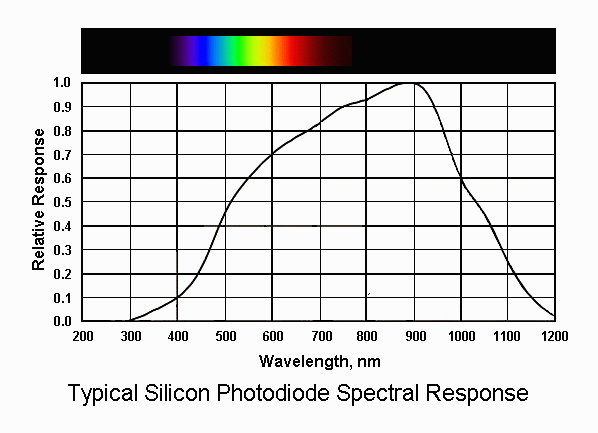
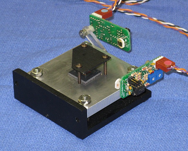
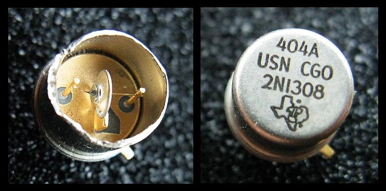
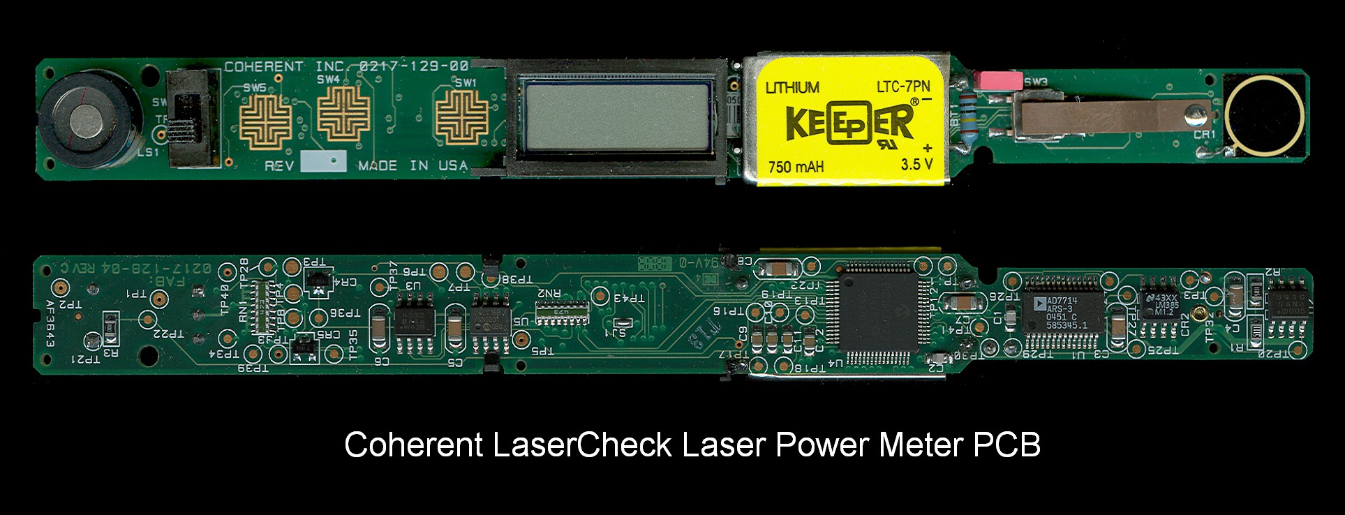
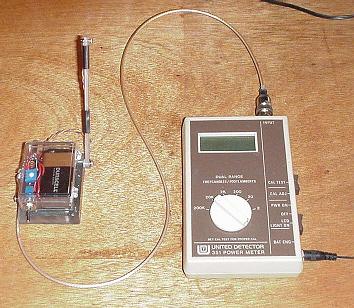
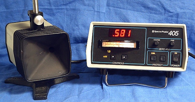
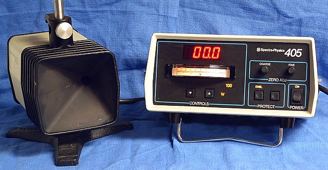
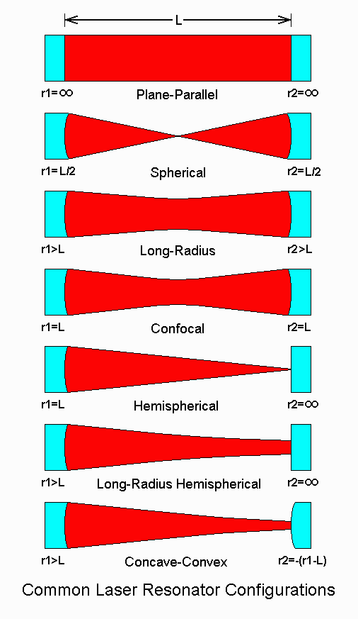
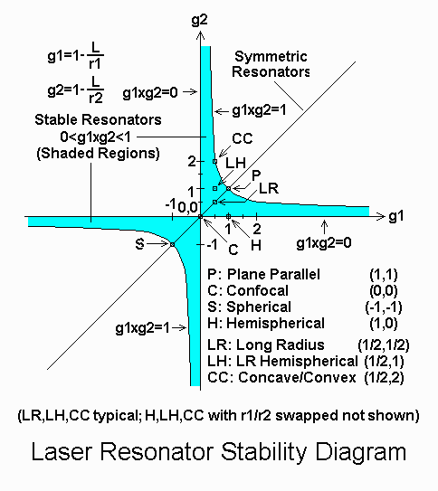
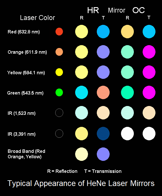
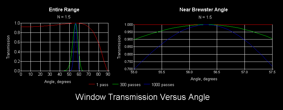
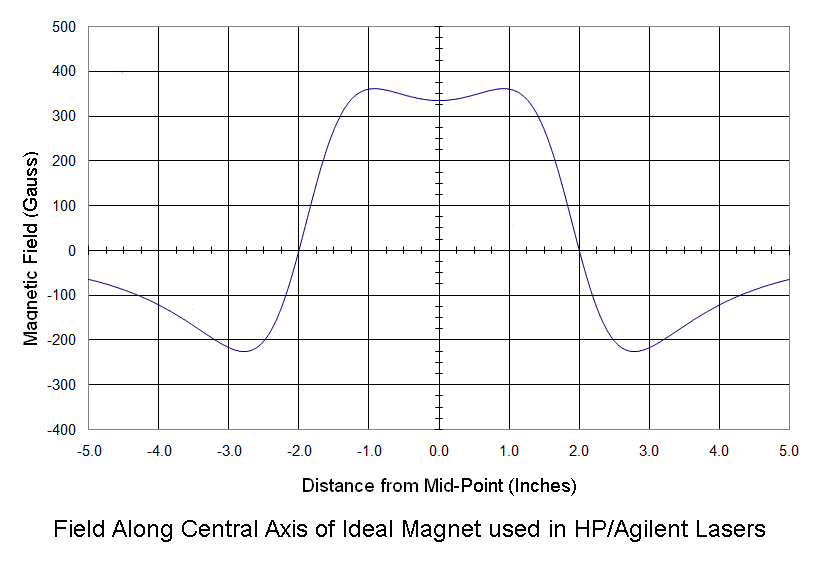
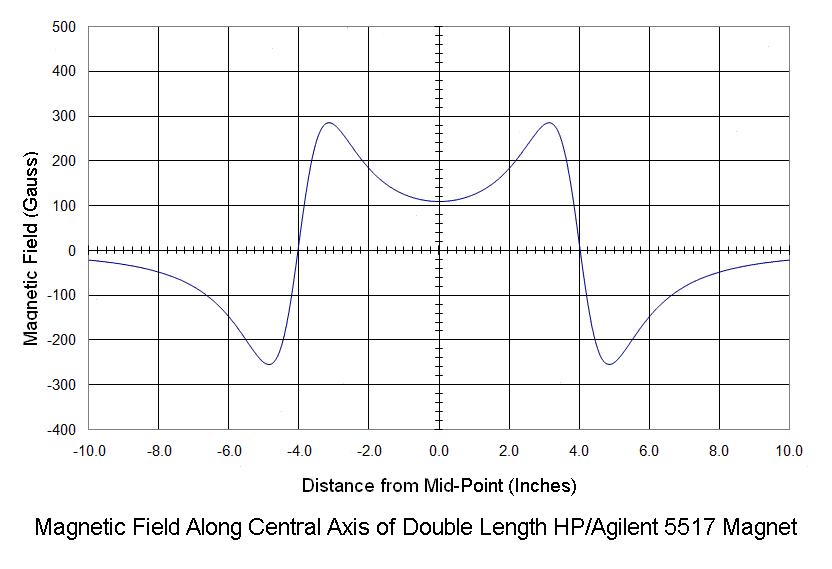
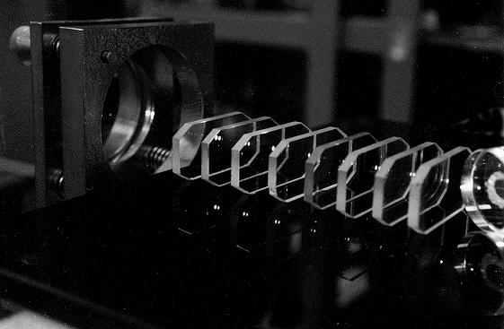
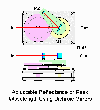
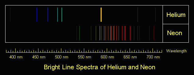
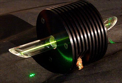
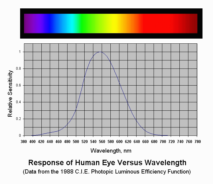
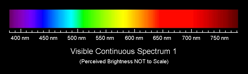
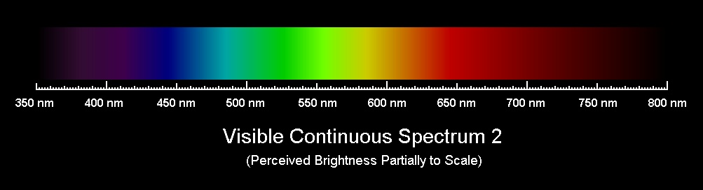
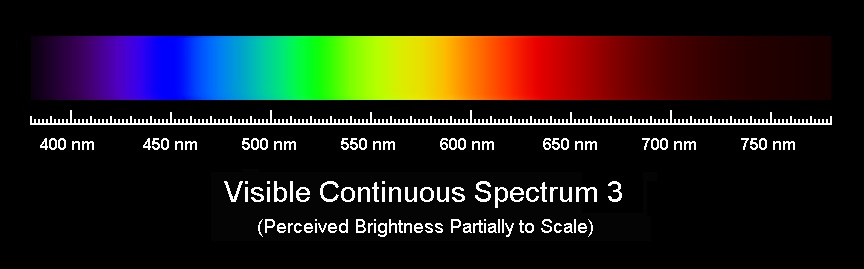
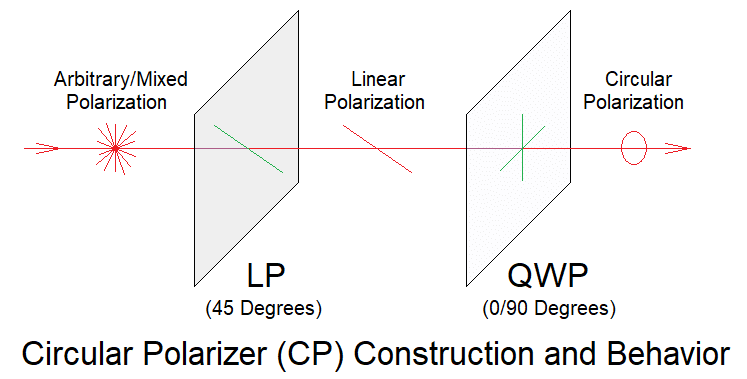
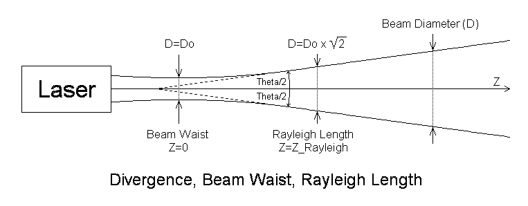
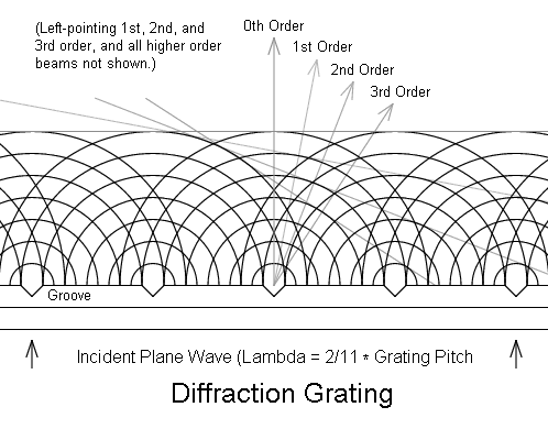
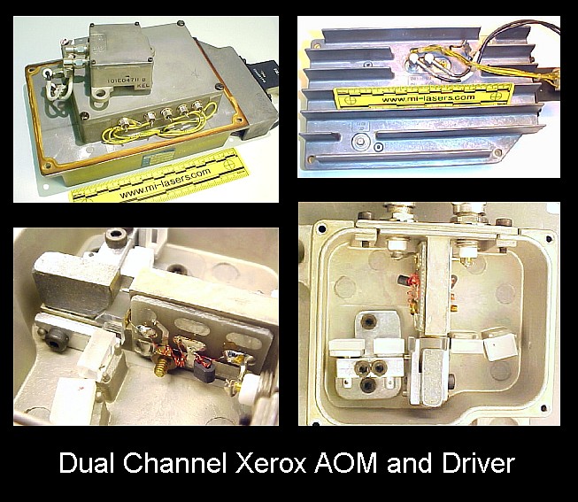