The original laser invented in 1960 was a solid state laser. It used a synthetic ruby rod (chromium doped aluminum oxide) with mirrors on both ends (one semitransparent) pumped with a helical xenon flashlamp surrounding the rod. The lamp was similar to what is used for indoor and high speed photography. The intense flash of blue-white light raised some of the chromium atoms in the matrix (the aluminum oxide is just for structure and is inert as far as the laser process is concerned) to an upper energy state from which they could participate in stimulated emissions (see the chapter: What is a Laser and How Does It Work? for a brief explanation if this isn't familiar to you. The result was an intense pulse of coherent red light at 694.3 nm - the first ever laser light in the world. Gas and semiconductor lasers followed closely behind but only the SS laser can claim to be first.
It was found early on that these lasers could burst balloons and blow holes in razor blades and someone even attempted to coin a new measure of laser energy to be measured in 'Gillettes' based on how many razor blades could be holed at once. :) And, the popular notion that hand-held death ray weapons would soon follow are based on these sorts of demos of solid state lasers, not on whimpy gas lasers (though the carbon dioxide laser is actually a much more likely candidate being the classic heat-ray of science fiction)!
SS lasers are used in all sorts of applications including materials processing (cutting, drilling, welding, marking, heat treating, etc.), semiconductor fabrication (wafer cutting, IC trimming), the graphic arts (high-end printing and copying), medical and surgical, rangefinders and other types of measurement, scientific research, entertainment, and many others where high peak power and/or high continuous power are required. A high energy pulsed YAG laser has even been used in rocket propulsion experiments (well, at least to send an ounce or so aluminum projectile a few feet into the air using just the pressure of photons!). The largest lasers (with the highest peak power) in the World are solid state lasers. Many of the laser projectors for light shows and for other laser displays use solid state rather than gas lasers like argon or krypton ion. And, that green laser pointer is a Diode Pumped Solid State (DPSS) laser.
The exact wavelength of the strongest lasing lines depends on the actual host material but usually doesn't vary that much. In addition to Nd:YAG and Nd:YVO4 at 1,064 nm, examples that lase at slightly shorter wavelengths include Nd:LSB at 1,062 nm, Nd:Glass at 1,060 nm and Nd:YLF at 1,053 nm. However, the lasing wavelengths of some like Nd:LiNbO3 (niodymium doped lithium niobate, 1,084 nm and 1,092 nm) are longer and further away.
Other materials include holmium doped YAG (Ho:YAG) or Ho:YLF. These lase at around 2,060 and 2,100 nm respectively. In the fiberoptic arena, erbium doped glass (Er:Glass) may be used in optical repeaters and amplifiers at around 1,540 nm. Er:YAG lases at 2,840 nm.
Beyond these, there are not that many examples of widely used commercial solid state lasers though many other materials are capable of the population inversion needed for laser action. The workhorse by far is still Nd:YAG with Nd:YVO4 becoming increasingly important for low to medium power (up to a few watts) 1,064 nm and frequency doubled 532 nm (green) diode pumped solid state lasers.
Energy output is measured in joules (Watt-seconds) per pulse. Multiply this by the number of pulses/second to calculate average power output. To determine the peak power in each pulse requires a knowledge of the pulse shape.
Flashlamp pumped SS lasers are used where high peak power is required as most other pumping methods can't even come close. However, the average power and efficiency may be quite low compared to approaches using high power laser diode pumping (see below).
Power output is measured the same way as for other CW lasers.
Depending on the application, the average power output or peak pulse energy or power may be the relevant measurement of performance.
Note that while this output if frequency doubled to 532 nm (green) would appear CW to the human eye, it would NOT be suitable for laser TV or light show scanning since it really isn't continuous.
(From: Anonymous (localnet1@yahoo.com).)
A (laser) diode pumped Nd:YAG may have a 40% efficiency (operating multimode with good thermal control of the diodes), and the pump diodes themselves have about a 45% efficiency, resulting in a net 18% of efficiency from electrical power to the diodes to output beam power. However, at increased pump powers, thermal issues may cause the efficiency to decrease after a certain point. This decrease is power dependent, as well as resonator and pump assembly design dependent.
Unlike HeNe and Ar/Kr ion lasers, there is little standardization of solid state laser components. Laser rods come in all shapes and sizes - some not even rod-shaped :) with or without mirrors (for use with external mirrors and Q-switch optics). They are also relatively expensive as despite their deceptively simple appearance - partly due to the fact that they are a lot fewer of them than laser diodes or HeNe tubes. A price of $300 for a 75 x 5 mm Nd:YAG rod could be a bargain.
The most common type of solid state lasers to have shown up on the surplus market are the laser head assemblies and pulse forming networks from some versions of the M-60 and M-1 tank rangefinders. Yes, if you come across a blown up M-60 or M-1 battle tank in your local junk yard, there may be a laser in there you can salvage! But don't worry, most of the time, you just have to take the laser. :)
In fact, building a solid state laser if you have a Nd:YAG rod with integral mirrors in-hand is very easy - just add a linear flashlamp of with enough energy in close proximity wrapped in degreased aluminum foil! For small rods, a single-use (disposable) pocket camera flash will even work. See the paper: Micro-Laser Range Finder Development: Using the Monolithic Approach.
My first contact with lasers was in the late 1960s when I inherited a student built ruby laser based on a design from Popular Science magazine archived on the Modern Mechanics blog Web site at Popular Science: PS Builds a Laser and so can you. This used a ruby rod with integral dielectric mirrors about 1/4" x 3" (this is all from memory) and a linear flashlamp with an energy input of up to 400 W-s. Regrettably, I don't know if it ever worked - the lamp fired fine but I was too chicken to turn the capacitor voltage up to its maximum setting for fear of blowing up the flashlamp! Oh well. :( At least, shortly after that, our high school acquired a *real* 1 mW HeNe laser so I played with that some and used it to view the hologram that was part of an issue of, I believe, Scientific American. Not the same as exploding balloons or drilling holes in razor blades, however. :(
The Laser Equipment Gallery has many detailed views of various solid state lasers from the M-60 Tank rangefinder to a high power arc lamp powered system putting out over 100 W CW.
Some people may only the first one to be a true microchip laser due to the small size of the lasing crystal but I include the other two since their designs are similar. However, in all cases, the only reason the lasing chip is so large in comparison to the active volume is due to manufacturing, handling, mounting, and thermal considerations. Thus, in principle, for the 100 mW green laser, a microrod say 1.2 mm long x 0.2 mm in diameter would be all that is actually required. But until laser chips are fabricated like computer chips and a way is found to get rid of the waste heat, much more material must be used. And, it is the thermal problems that ultimately limit performance - these tiny bits of lasing crystal are potentially capable of much more power output than can be obtained without them being damaged from heating. The smallest mass produced microchip laser crystals I know of are the CASIX DPM0101 hybrid vanadate-KTP module used in some green laser pointers: 1x1x2.5 mm. With cooling on all 4 sides, these may be capable of more than the small number of mW required for a pointer. The larger DPM0102 can generate over 50 mW intermittently at least (but the glue used to cement the two crystals may be damaged by the high intensity green light after awhile).
Melles Griot's low to medium power high quality green DPSS lasers now use composite crystals similar to CASIX's but of their own design optically contacted, not glued, so there is no problem with high intracavity flux. They use optics to shape the pump beam and active TEC cooling so these are much better than laser pointers (and of course cost a lot more as well!). I was told that the cavity is something like 1.5 mm in length (unconfirmed) so this is even shorter than the DPM0101 but it probably has a cross-section more than 1x1 mm. The models currently available produce up to 20 mW but they have gone much higher in the lab. See the section: The Melles Griot 58 GCS Series Green DPSS Laser for more info.
Unlike lamp pumped rod based side-pumped SS lasers which may use much of the volume of the laser rod, end-pumped DPSS lasers typically shape and focus the diode pump beam to a very narrow waist to boost the power density in the lasing crystal and to match the TEM00 mode volume of the cavity. This is an extremely efficient process compared to that of a lamp pumped laser. The typical conversion from diode pump light to IR laser output is over 33%. Compare this to a typical efficiency of 1% for a lamp pumped YAG laser. A DPSS laser may have a better than 10% wall plug efficiency for IR and frequency doubling efficiency (from 1,064 nm IR to 532 nm green) may exceed 50 percent.
Since microchip lasers can use so little actual lasing material and the pump diodes are also very small, they can be very compact, and potentially mass produced and inexpensive. In addition to green laser pointers and low to medium power DPSS IR and green lasers based on YAG or vanadate, all sorts of other SS lasing materials can be used. Of particular interest for communications are erbium (Er) doped materials which lase around 1,530 nm, a wavelength which is optimal for fiber-optic cable.
Microchip lasers also don't necessarily need high pump power. Depending on type, cavity design, and pump beam shape, a few mW of pump beam may be enough to exceed the lasing threshold and they have very high slope efficiency (percent increase in laser output versus increase in pump input) as well.
(From: Doug Little (dmlittle@btinternet.com).)
Like other lasing mediums, the output power from a YAG, ruby, or similar solid state rod will rise according to pump energy - but only up to the point where the active lasing medium is saturated (i.e. all the dopant ions are raised to the upper state). Beyond this point, no amount of extra pump energy will make any difference beyond generating unwanted waste heat. Also, a low-% doped crystal will reach this state more quickly, and will have a longer fluorescence period because the laser 'chain reaction' is inhibited by a reduced population of contributing ions - something like sticking carbon rods in a nuclear reactor to slow it down (well, that's how I like to think of it but feel free to flame, grill, or laser zap me if you think it's a bad analogy :-)
(From: Sam.)
Actually, I think it is an excellent analogy. Just think of all those mouse traps in the upper energy state! :)
(From: Doug.)
The saturation thing is a fairly obvious point, but it would be unfortunate to see enthusiasts building some huge 6-lamp device with a tiny pink ruby rod to find that they get the same output as they could achieve with 2 or 3 lamps! :-)
It would also be nice to have a good clear explanation of doping percent differences and what effect this typically has on laser action. It can make a big difference when you are designing a laser that will work properly even with reasonably well known pump energies.
(From: Sam.)
Yes, the last item would be nice. Are you volunteering? :) However, realistically, where the laser rod is surplus, there probably isn't any easy way to determine the doping percent or control it!
(From: Bob.)
There are all sorts of things that limit the amount of output energy or power from a given size crystal including: damage threshold of the laser medium, energy storage capacity of the laser medium, thermal considerations, and optical considerations (such as self focusing and thermal lensing). You can scale any laser, but there comes a point where you have to make the laser bigger to get more energy. Look at the NOVA laser at Lawrence Livermore National Labs: The light starts out in a small laser rod that could be placed in the palm of your hand, then it gets amplified in a chain of laser amplifiers that take up the area of a football STADIUM!
(From: Ed Xavier Gonzalez (ohlaser@flash.net).)
"Short pulse YAGs can do considerable damage, and can possibly ignite insignificant metals without warning. I have (on only one occasion) accidentally ignited some very fine stainless steel powder. I thought that was impossible until I read the MSDS on some commercially available material. Long pulse YAGs will burn very deeply and can do biological damage if not handled with respect (experience talking). Typically, long pulse YAGs mark alumina ceramic and stainless very well without removing much material. The short pulse YAGs will definitely remove material, but have a tendency to ablate rather than mark."
The document: Safety Guidelines for High Voltage and/or Line Powered Equipment should be thoroughly studied before even thinking about working on any of the power supplies for solid state lasers. ALWAYS assume the capacitors are charged - never assume they are safe to touch even if the laser has been left unplugged for weeks!
More information on the specific electrical dangers are outlined below.
There are several potential hazards in dealing with the innards of electronic flash, solid state laser power supplies, and other xenon strobe equipment.
High voltage with high energy storage is an instantly deadly combination. Treat all of these capacitors - even those in tiny pocket cameras with the same respect as a loaded gun or stick of dynamite. Always confirm that they are fully discharged before even thinking about touching anything. On larger systems especially, install a shorting jumper after discharging just to be sure - these types of capacitors commonly recover a portion of their original charge without additional power input. In the case of an SS laser capacitor bank, it doesn't take a very large portion to be fatal. Better to kill the power supply than yourself if you forget to remove the shorting bar when powering up the unit.
Some links:
Reading and following these recommendations and heeding the warnings is especially important when working with high power solid state laser power supplies or xenon strobes of any kind.
For solid state lasers provided as kits of parts (which is probably the most common for types like Nd:YAG or ruby other than the M-60 rangefinder), be aware that the only type that can likely be made to work easily are those that are flashlamp pumped unless you have access to high power laser diodes of the proper wavelength. The rod must be optically polished and coated (HR, OC, or AR as appropriate) - you won't do that in your basement. See the section: Grinding and Polishing a Ruby Rod.
Using broad band sources like halogen lamps or the Sun for pumping is extremely difficult due to the limited range of wavelengths that matches the lasing medium's absorption spectrum and the huge amount of waste heat. And, any claims about CW operation for some of these are often totally bogus as the physics simply prohibits it.
(From: Chris Chagaris (pyro@grolen.com).)
Commercial laser rods are typically finished with the following specifications: Ends flat to l/10 wavelength, ends parallel to ±4 arc seconds, perpendicularity to the rod axis to ±5 minutes, rod axis parallel to within ±5 degrees to [111] direction. These tolerances cannot readably be achieved by the home experimenter. All commercial laser rods also have anti-reflection coatings applied to their ends which must also be done professionally. If the mirrors aren't included or part of the rod itself, they will have to be purchased separately.
The CW pumping of ruby is not impossible but nearly so, with terrible efficiencies. The pumping of ruby or Ti:sapphire to threshold is literally impossible using tungsten-halogen lamps as has been suggested by some uninformed individuals. Ruby's main absorption bands are located at 404 nm and 554 nm and Ti:sapphire's peaks at about 490 nm. Tungsten-halogen lamps have an emission maximum at 840 nm which is very far from the either of these crystal's absorption bands. Radiation output at the blue and green wavelengths is very poor in these types of lamps, hence another major problem.
Finally, ruby has a very high excitation threshold, being a three-level system, despite its fairly long fluorescence lifetime of 3 ms (at 300K). In early experimental tests, a very small ruby rod (2 mm diameter x 50 mm length) was pumped by special capillary mercury arc lamps (good spectral match) and it took an input of 2.9 kW to produce a CW output of 1.3 watts. Only a small portion of the ruby was excited by the filament arc and laser action only occurred in 6 x 10⁻³ cm3. Using this data, the lamp input power per unit volume of active material to obtain threshold is about 230 kW per cubic centimeter.
While portions are quite technical with many equations, much of it can be read and understood without a fancy college degree. The book has been published in several editions betweem 1976 and 1999. The earlier ones (which may be available at reasonable prices from used technical book sellers) are probably better for pulsed lasers as some material on this topic has been dropped in the latest (5th) edition in favor of more coverage of diode pumped solid state lasers.
Some other relavent publications can be found in the chapter: Laser Information Resources.
There are a number of Web sites with laser information and tutorials.
In particular:
See the section: On-Line Introduction to Lasers for the current status and on-line links to these courses, and additional CORD LEOT modules and other courses relevant to the theory, construction, and power supplies for these and other types of lasers.
The basic structure of the SS Laser hasn't changed in any fundamental way since its invention in 1960. A transparent rod (most common shape) doped with a small amount of impurity (the actual lasing medium) is optically pumped by a light source (most commonly one or more linear xenon flashlamps or an array of high power laser diodes) whose spectrum contains significant energy at wavelengths matching one or more of the absorption lines of the lasing medium. One or both mirrors are either an integral part of the laser rod or external. A Q-switch device is often included to compress and boost the energy in the output pulse (pulsed or quasi-pulsed lasers only) with some loss in total energy or average power at the fundamental wavelength. Additional devices such as an intra-cavity frequency harmonic generation crystal (most commonly, doubling - second harmonic generation or SRG) or external Optical Parametric Oscillator (OPO) may be added. Total output energy or average power may actually increase compared to CW operation due to the non-linear behavior of these processes.
Properly selecting the cavity components and driving the pump source properly can make all the difference in terms of output pulse energy, beam quality, and stability.
Matching the PFN to the flashlamp, rod material, and cavity optics is critical in achieving efficient (as these things go) pumping of the laser. For example, just one parameter - the flashlamp pulse duration - can easily determine whether a modest input energy will result in an output beam, whether 10 times this energy will be needed, or whether it the laser will do anything at all. For a given total pulse energy, if the pulse duration is too long, lasing will be erratic or non-existent. Normally, it should be designed to be shorter than the fluorescence lifetime of the lasing medium. As the pulse becomes shorter and shorter, the peak output power and pulse consistency will approach that of a Q-switched laser. However, designing a PFN for a very short pulse is difficult and expensive, and the flashlamp must be derated and its life reduced for very short pulses. Thus, practical direct drive schemes can never compete with Q-switching. The PFN for a typical non-Q-switched Nd:YAG laser will produce a 100 to 200 us pulse which is well matched to the Nd:YAG's 230 us fluorescence lifetime but will result in a series of variable size pulses rather than a single short large one.
See the chapter: SS Laser Power Supplies for more information.
However, most of our attention will be devoted to the common rod shape for lamp pumped solid state lasers and "microchips" for diode pumped solid state lasers.
Other important solid state lasing materials include:
Some additional notes on the comparison of amorphous (glass) and crystalline lasing material:
(From: M. C. D. Roos (roosmcd@dds.nl).)
Straight out of my text-book (1975 and first edition):
"Glass laser hosts are optically isotropic and easy to fabricate, posses excellent optical quality, and are hard enough to accept and retain optical finishes. In most cases glasses may be more heavily and more homogeneously doped than crystals, and in general, glasses posses broader absorption bands and exhibit longer fluorescence decay times. The primary disadvantage of glass are its broad fluorescence line widths (leading to higher thresholds), its significantly lower thermal conductivity (a factor of 10, leading to thermally induced birefringence and distortion when operated at high pulse repetition rates or high average powers), and its susceptibility to solarization (darkening due to color centers which are formed in the glass as a result of the UV radiation from the flashlamps). These disadvantages limit the use of glass laser rod for CW and high-repetition rate lasers."
Nd:YAG has been effectively pumped by various sources including flashlamps (xenon and krypton), krypton CW arc lamps, tungsten-halogen lamps, and high power laser diodes. At current densities of lass than 4,000 A/cm2, both xenon and krypton have a good match with the absorption curve of Nd:YAG laser material. Even some more exotic methods have been used, such as sun-pumped, flashbulb-pumped, and explosively-pumped. The availability of high quality surplus Nd:YAG rods at reasonable prices on the surplus market make this material very attractive to the home-experimenter. Using one of these to make a flashlamp pumped pulsed laser is quite easy.
Nd:YAG, Nd:YVO4, and Nd:YLF are common in diode-pumped lasers. But, the most effective is the newly developed laser crystal Nd:LaSc3(BO3)4 or Nd:LSB. Nd:LSB has has absorption and radiation cross section similar to Nd:YAG but the bands are five time wider. The absorption coefficient of Nd3+ (10%at) in LSB is three times higher than Nd:YAG. LSB can be very heavily doped with Nd3+ (until 50%at), which provides record efficiency in the end-pumped configuration. This is a very high level in comparison with YAG (1.2% before luminescence quenching) or YVO4 3%, and 1.5% YLF. Furthermore, the saturation intensity of Nd:LSB is five times bigger than those of YAG or LSB.
For example, using a microchip 0.5 mm thick and 2 to 3 mm in diameter, is is possible to obtain 0.5 to 50 mW of green output at 531 nm. Q-switch mode in such a microchip is possible with a Cr4+:YAG absorber. On LSB with KTP for SHG grown in Russia, BREMLAS is producing powerful green lasers with cubic inch dimensions. A 10 W green microlaser is under development.
The wavelength for vanadate is more precisely 1,064.3 nm. There is also a weaker line at 1,342 nm.
(Portions from: Juozas Reksnys (rexnys@uj.pfi.lt).)
This most powerful lasing Nd:YAG line is composed from two lines 1,064.17 nm (strong line) and 1,064.4 (week line). At room temperature, the half-width of lasing line is 6.5 cm-1 which exceeds the distance of 2 cm-1 between two lines. Therefore, they are a joint line.
The wavelength of this line depends on temperature. In the practical range of +/-60 °C, it linearly shifts to longer wavelengths during heating by 5x10⁻³ nm/deg. At 27 °C (300 °K), the center of the lasing line is at 1,064.15 nm.
In addition to the common 1,064 nm wavelength, Nd:YAG has over a dozen other weaker lasing transitions between 1,052 nm and 1,444 nm.
(From: Sam.)
However, the vanadate and YAG wavelengths are close enough (0.15 nm) that a lamp or diode pumped YAG crystal can be used as an amplifier for the output of a vanadate laser in a (MOPA - Master Oscillator Power Amplifier) configuration since the gain bandwidth of YAG is about 0.5 nm.
KGW has a NICE broad absorption spectrum, that makes it a lot easier to work with than YAG BUT its thermal properties are poor.
I have a paper titled "Generation of visible light with diode pumped solid state lasers" by Boller/Bartschke/Knappe/Wallenstein from 1993 that was published in "Solid State Lasers: New Developments and Applications" Edited by M.Inguscio and R. Wallenstein, Plenum Press, New York, 1993. This long paper (17 pages) focuses on NYAB. The authors state: "We report the so far highest 531 nm output power of 130 mW generated with 1.55 Watt of diode pumping."
(From: Milan Karakas (mkarakas@vk.tel.hr).)
I have a Nd:KGW rod 5 mm diameter x 50 mm long. This is a neodymium doped potassium-gadolinium tungstate single crystal. This crystal has a Nd doping of 3% and operates at 1067.2 nm with 4 to 6% efficiency (Q-switched, 6.3 mm x 75 mm at 50 Hz), 3% efficiency CW, and 60% efficiency when diode pumped laser (quasi CW). The lasing threshold is extremely low - 0.2 - 1 J! I have not found reasonably priced optics for this laser (we may use optic for classic Nd:YAG, because wavelength is close) and pump source with low thermal emission (808 nm laser or LED). The rod was inexpensive - $209 USD including DHL shipping and duty.
(From: Bob.)
NYAB is a self-doubling (combined lasing and non-linear crystal) but it has a much lower doubling efficiency than traditional vanadate/KTP or YAG/KTP. The numbers I have seen are on the order of about 30 mW out for 1 W of diode pumping (efficiency is much higher with Ti:Saph pumping, but it's kind of inconvenient to have a such a laser pump a 100 mW 532 nm system, not to mention expensive. :)
The following is from a 1990 paper so better performance is likely: "Work on diode-pumped self-doubling lasers is still in the early phases of development. The most attractive nonlinear gain medium is Nd:YAB, which is a dilute form of the stoichiometric neodymium compound neodymium aluminum borate (NAB). Diode-pumped Nd:YAB lasers with output powers in the milliwatt range have been demonstrated (reference 10.67)"
There are slight variations in the peak wavelengths for different types of Nd doped glasses. These differences are only very slight and should not be of great concern. The following are some glass types and peak emission wavelengths:
Ruby rods for lasers are made synthetically. Aluminum Oxide (Al2O3) with a very small amount of chromium impurity is melted in an induction furnace. A seed crystal (perhaps a natural ruby or a chip off another synthetic crystal) is stuck into the melt on a rod then slowly withdrawn. A cylindrical rod of "ruby" crystal is formed and is slowly pulled out of the melt. This rod is then cut up and ground with diamond machining equipment to form the precisely shaped laser rod. The ends are polished to extreme levels and then treated with whatever optical coatings are desired, depending on the design of the laser (i.e., mirrors directly on the rod or external).
(From: Mark W. Lund (mlund@moxtek.com).)
There are several ways to do this. The first is the easiest, to pull from the melt. You can melt Al2O3 in molybdenum crucibles and pull a crystal directly from the melt. Even single crystal tubes and other shapes having a fixed cross section can be pulled using a technique called "edge defined growth." Unfortunately, because of the incredible temperatures that sapphire melts at any dopants that you might want to use vaporize, so you can't make red or blue material, only water-white material.
If you want colored sapphire or ruby there are two more methods used. The first, Vernuile (sp?), uses a hydrogen-oxygen flame and drops powdered Al2O3 plus dopant through the flame. The flame melts the powder, which falls on the seed crystal and crystalizes. Because only the surface of the crystal is molten the dopant gets incorporated into the bulk. The crystals are called boules, and look vaguely like a pop bottle, with a small neck, opening up into a cylindrical crystal. The stresses are so enormous in these boules that when you snap the neck off the entire crystal breaks into several pieces along the axis of the boule. Most colored sapphire and ruby sold is made this way, including the watch jewels.
The last method used commonly is flux growth. The Al2O3 is dissolved in a molten salt, usually lead oxide plus cryolite, in a platinum crucible. The crystals come out of solution as the melt is cooled just like sugar in hot water. These are the most desirable of the synthetic stones because they look more like natural stones after cutting, and the process is the most expensive.
(From: Fred Perry.)
Actually, Union Carbide in Washougal Washington makes synthetic Ruby and other colored variants of Al2O3 (sapphire) by the Czochralski method. I bought an nice big CZ 'ruby' gemstone from UC at CLEO a few years ago. You are right that it is hard to get dopants to dissolve in the pot; but this is more a limitation on max concentration and hence achieved depth of color than something that can't be done at all. UC in fact makes (sole source - patented) the 'ruby' laser rods that were discussed in another post this week. They are pink, not red.
(From: Mark.)
Hmm, whom am I going to believe, Fred, whom I have a lot of respect for, or me, whom I have to live with? CZ is usually the method of choice if you can grow a crystal, but I have never seen a paper or patent on CZ growth of colored sapphire. I can't imagine going through all the pain and cost of flux growth or Vernuile if you could pull it from the melt. The method of choice for lasers, by the way, was flux growth when I last looked. On the other hand, if anyone could do it it would be Union Carbide, and it has been a few years since I did search the literature.
I can imagine that some kind of sealed high pressure CZ puller could drive the dopants back into the melt.
Of course the dopant level of a ruby laser is much less than a gemstone. How do they grow titanium doped sapphire? Anyone know?
(From: charlesk@vloc.com.)
As Fred pointed out UC grows ruby by Czochralski as does VLOC (without patent violations, mind you) and we do it quite well as pointed out by the Rogers (Thanks for the recommend). Mark, Czochralski is the preferred method for ruby growth for lasers, has been for a while. Now Ti:Sapphire is a different story, probably due to the higher dopant levels as you surmised. Crystal Systems can probably answer that point.
There is more information on the VLOC Web Site.
"Does Nd:YAG material yield interesting gems when cut? Is it actually considered a "gem"? I think I have a piece of scrap material left over after a bunch of laser rods were cut from it. It's interesting to show to people because it appears transparent to slightly yellowish under most fluorescent illumination, but becomes magenta/pink under full-spectrum illumination."
(From: Chris Cox (ccox@slip.net).)
Yes, and gem faceters like it. Nd:YAG is considered a man-made gem material. It will go almost clear under some more recent rare-earth fluorescent lamps (which confused me when I brought some home. ;-)
There are many types of these crystals, which are referred to as "color change" materials in lapidary/gemstone circles.
(From: Uncle Al (UncleAl0@hate.spam.net).)
Ditto glassblowers' didymium glass lenses and the fabulous gem alexandrite, sunlight versus candle light or incandescent illumination (blue in sunlight, red in cool illumination).
See: "Man-Made Gemstones" by Elwell.
Laser crystals make more than passable gems if they are hard enough to retain facetting and especially if they are optically isotropic. Pale laser ruby doesn't look like much, but if you give it a megarad of Co60 gamma (piggyback on a medical sterilization) you get a superlative tawny orange. (Facet first, because warming to above 100 C gives F-center decay and an eerie deep red glow as it returns to pale pink).
(From: A. E. Siegman" (siegman@stanford.edu).)
I also have a vague memory that maybe there was a diamond solid state laser doped with Cr or Fe or a RE at some point way back, but I'm not sure about that, and you'll have to do the digging in some of the standard handbooks of laser transitions to check if this is correct.
If by a "diamond laser" you mean in general "diamond as the host material, doped with something as the laser atoms", well then diamond is just another host, competing with YAG, sapphire, etc It might have some useful attributes in competition with these others -- thermal conductivity, fracture strength, ability to polish -- but the others are already generally pretty good, and diamond isn't likely to be a miracle material in comparison.
An interesting connection between diamond and laser technology is that some diamonds have small internal flaws that are visible because they contain some uncrystallized carbon or other impurities. If you use laser drilling to drill a tiny tunnel in to the hole and vaporize out the impurity, the remaining tunnel and empty void inside the diamond become much less visible because of the high index of diamond, and the diamond's value as a gemstone can be substantially increased. I believe this practice is in routine commercial use.
I recall that in the '60s I had a visitor who was in the diamond industry and wanted to start up a venture to implement this technique. Getting involved in that kind of imaginative venture wasn't my thing at the time (or ever, I'm afraid), so I didn't jump at the chance -- maybe I should have.
Of course there was also the marine researcher who wanted to develop a CO2 laser gun to brand serial numbers on whales as they surfaced, to make marine surveys more accurate -- and the student who wanted to mount a similar laser on a pickup truck to brand cattle on the fly, which I think later actually got tried somewhere, and may in fact be a good idea. And so on.
(From: Harvey Rutt xh.ruttx@x.ecs.soton.ac.uk).)
And in our lab then the guy who wanted to slice mushrooms which apparently difficult commercially (can't keep the knives sharp enough it was claimed), and substantial money was spent on slicing up foamed toffee brittle into bars with lasers (it sticks to the slitting knives...) but the customers didn't like the caramelised taste!
However, RE: diamond.
Aside from the 'technological' issues such as thermal conductivity, toughness and hardness etc there are some more fundamental issues which don't seem to have been mentioned.
If you go for a dopant system, you need solubility of the dopant. Diamond is a strongly covalent lattice, with a very small covalent radius. This will make it hard to get the typical laser ions in in any reasonable amount in the right valence state. Also the crystal field strength and symmetry at the impurity site has to be 'right' to provide appropriate energy levels (Tanabe Sugano diagrams, if I spelled it right); they will be very different in diamond I suspect, and might need different dopants and level schemes. So you might be looking to unconventional, small atom impurities with a liking for covalent sites, like nitrogen which is well known in diamond; but are there any suitable level schemes?
You also need good (low) non radiative relaxation rates from the upper laser state; but diamond must have very high phonon energies (light atoms, strongly bound) which correlate with high non radiative rates. This will be especially bad for IR transitions (its the photon to phonon energy ratio that matters, if less than 5 or 6, trouble usually.)
If you tried to do a diode laser, I assume diamond is an indirect semiconductor like Ge and Si? (I don't know - does anyone?) and I think injection diode lasers are not possible in an indirect gap material - aside from getting adequate doping densities and profiles, but thats mere technology :-)
A colour centre laser? That might be the best bet, if some diamond colour centre has suitable levels. But it must be said the many conventional alkali halide, etc., colour centre lasers were all a bit pathetic and have been dropped.
(From: Professor Siegmen.)
Harvey's comments, as always, informed, to the point, and well put.
Just in case it might be of interest to the OP, I believe there were at one time some experiments on doped s-s lasers in another gemstone material, emerald, and they also seem to have been dropped.
Also, alexandrite (is that considered a gemstone?), which does offer some special advantages and was commercialized by a company called Light Age, spun out of Allied Chemical, though it's not been a roaring success.
A ceramic is formed by using heat and pressure to merge a nano-fine powder of the desired material at slightly below its melting point. The result is not a single crystal but an aggregate of small crystals. Nonetheless, the ratio of crystal volume to grain boundary volume is so large that the lasing behavior is almost identical to that of a single crystal (i.e., the result with Nd:YAG is a homogeneously broadened gain profile just like the crystalline host).
There are a number of benefits to using a ceramic rather than a crystalline host. Some of the most important include:
While performance is not quite as good as with single crystals, it's getting there. Expect a ceramic solid state laser in your future!
Flashlamps are the method of choice where high peak power is required. None of the alternatives can produce the short, high intensity, burst of light needed to pump a solid state laser for the generation of optical output pulses with peak power measured in Megawatts or more. While the xenon flashlamp is most common, other gas fills may be used to tailor the output spectrum to more closely match the absorption bands of the solid state lasing medium. However, none are really that great and most of the light ends up as waste heat that must be removed - one of the major limitations on maximum pulse rate.
Arc lamps were used in the past where CW operation was required. However, a major difficulty with these was the need to remove kWs or 10s of kW of waste heat from the lamp, rod, and cavity components. Circulating water or oil was needed along with a separate 'chiller' unit for cooling. Arc lamps are rapidly being replaced by arrays of high power laser diodes which are at least 10 times more efficient partially because their output is at the precise absorption wavelength of the solid state lasing medium. They can usually be convection or force air cooled and operate from a regular 115 VAC outlet.
Other types of light sources including the Sun and halogen lamps have been used where the physics permits (Nd:YAG, for example), but their efficiency is very low and the heat dissipation problems are significant. Due to the continuous spectrum produced by these sources, the percentage of light that matches the absorption bands of the solid state lasing medium is quite small. And, for the halogen lamp, at most 10 percent of the electrical input power ends up as visible light to begin with (the rest is IR or heat with a bit of UV).
(From: Leonard Migliore (lm@laserk.com).)
There are lots of CW Nd:YAG lasers. Laser markers are, most commonly, CW-pumped Q-switched Nd:YAG lasers. The rod (or slab) is generally immersed in water, with illumination by arc lamps or diodes going through the water. They get very unhappy with even a momentary loss of cooling.
The laser mode is quite sensitive to the amount of heat being pumped into the rod; they only work properly over a narrow range of lamp currents. I don't think you could get any output out of an air-cooled YAG rod before it cracked.
There are many possible configurations. Which one is used may depend on many factors including the type and shape of the lasing medium (rod, slab, etc.), cooling requirements, and cost:
The cavity reflector is often made of polished metal formed or milled to the desired ellipsoidal or other shape. However, some lasers may use a compacted white powder coating on the outside of the glass or quartz flow tube holding the rod and lamp(s) or between flow tubes. The exact composition isn't critical as long as it has a high reflectivity and is stable. One such material contains barium sulfate. See: Labsphere. Search for "white coating". Another one is magnesium oxide. Similar products are available from Edmund Scientific (actually made by Kodak). It is sprayed on from a can. In general, I wouldn't recommend attempting to remove these sorts of coatings unless they are visibly damaged.
A common model of linear flashlamp is the EG&G FXQ-1300-2 which has a total length of 115.8 mm long, 4 mm outside diameter, and 2 mm inside diameter.
For the FXQ-1300-2, above, the rating is 500 V.
For the FXQ-1300-2, the maximum explosion energy is 140 joules at a 100 us pulse duration and 500 joules at 1 ms.
See EG&G 1300 Series Linear Flashlamp Specifications and Links for detailed info on the other models.
Here are some notes on the K factor and its relationship to flashlamp voltage and current:
(From: Don Klipstein (don@donklipstein.com).)
For more, see the section: Flashlamp and Arc Lamp Manufacturers and References.
Mechanical specifications:
              Bore   Arc     Tube    Overall
  Flashlamp   Size Length  Diameter  Length
    Type      (mm) (in/mm)   (mm)    (in/mm)
-----------------------------------------------
 FXQ-1300-1    2    1/25      4     3.56/90.4
 FXQ-1300-2    2    2/51      4     4.56/115.8
 FXQ-1300-3    2    3/76      4     5.56/141.2

 FXQ-1301-1    3    1/25      5     3.56/90.4
 FXQ-1301-2    3    2/51      5     4.56/115.8
 FXQ-1301-3    3    3/76      5     5.56/141.2

 FXQ-1302-2    4    2/51      6     4.56/115.8
 FXQ-1302-3    4    3/76      6     5.56/141.2
 FXQ-1302-4    4    4/102     6     6.56/166.6
 FXQ-1302-6    4    6/152     6     8.56/217.4
 FXQ-1302-10   4   10/254     6    12.56/319.0

 FXQ-1303-2    5    2/51      7     4.56/115.8
 FXQ-1303-4    5    4/102     7     6.56/166.6
 FXQ-1303-6    5    6/152     7     8.56/217.4

 FXQ-1304-3    6    3/76      8     5.56/141.2
 FXQ-1304-4    6    4/102     8     6.56/166.6
 FXQ-1304-6    6    6/152     8     8.56/217.4

 FXQ-1305-3    7    3/76      9     6.06/153.9
 FXQ-1305-4    7    4/102     9     7.06/179.3
 FXQ-1305-6    7    6/152     9     9.06/230.1
 FXQ-1305-9    7    9/229     9    12.06/306.3
Electrical specifications:
All lamps listed are filled to a xenon pressure of 450 Torr. They are designed for convection or forced air cooling. Water cooling is not recommended. Lamps may operate with either series or parallel triggering and are supplied with a trigger wire. Minimum flashing voltage parameters assume an unloaded trigger pulse.
                                     Maximum      Minimum
               Ko       Minimum      Average      Trigger       Explosion
 Flashlamp  Impedance   Flashing    Power (W)   Voltage (kV)    Energy (J)
   Type    (ohm-A^0.5) Voltage (V) Conv Forced Series Parallel T=100us T=1ms
------------------------------------------------------------------------------
 FXQ-1300-1   16.2        400        25    50     12      15      70     250
 FXQ-1300-2   32.4        500        50   100     12      15     140     500
 FXQ-1300-3   48.3        600        75   150     12      15     210     750

 FXQ-1301-1   10.8        400        35    70     12      15      90     300
 FXQ-1301-2   21.6        500        70   140     12      15     180     600
 FXQ-1301-3   32.4        600       105   210     12      15     270     900

 FXQ-1302-2   16.2        500       100   200     12      15     240     780
 FXQ-1302-3   24.3        600       150   300     12      15     360    1170
 FXQ-1302-4   32.4        700       200   400     12      15     480    1560
 FXQ-1302-6   48.6        900       300   600     15      20     720    2340
 FXQ-1302-10  81.0       1300       500  1000     15      20    1200    3900

 FXQ-1303-2   13.0        500       120   240     15      20     340    1040
 FXQ-1303-4   25.9        700       240   480     15      20     680    2080
 FXQ-1303-6   38.9        900       360   720     15      20    1020    3120

 FXQ-1304-3   16.2        600       225   450     15      20     600    1800
 FXQ-1304-4   21.6        700       300   600     15      20     800    2400
 FXQ-1304-6   32.4        900       450   900     15      20    1200    3600

 FXQ-1305-3   13.9        600       255   510     15      20     660    2160
 FXQ-1305-4   18.5        700       340   680     15      20     880    2880
 FXQ-1305-6   27.8        900       510  1020     20      25    1320    4320
 FXQ-1305-9   41.6       1200       765  1530     20      25    1980    6480
The following are from the EG&G "High Performance Flash and Arc Lamps". EG&G is now part of EXCELITAS but they do not appear to have retained all of their products.
Explosion energy:
(Thanks to Doug Little for helping to put the following into a more consistent form.)
The explosion energy is the energy input at which a particular flashlamp is likely to fail after (or during!) a single shot at a given pulse width. As will be seen, longer pulses result in much higher explosion energy values. The calculation for explosion energy takes into account the parameters of the lamp that are fixed (material, construction, diameter, length) and those which change (pulse width, and the resulting current for a given energy). Keeping the equations separate helps clarify the difference between the fixed lamp specification and varying conditions for a given application.
For convenience (or to make this seem more obscure!), the fixed parameters are lumped into a single number called Ke, which could be printed on the flashlamp box because it is a constant for a given flashlamp.
Ke = Q * d * l
Where:
Typical values of Q vary from around 190 to 250 for a typical of xenon lamp, based loosely on the lamp's diameter. Older xenon lamps such as the FX-103C have an estimated Q of 194. The EG&G catalog gives the following typical values based on lamp bore (I believe this is ID): 8 mm - 246, 10 to 12 mm - 210, 13 mm - 200.
Special fast-risetime lamps (which are probably for dye lasers) basically double this value to 400 to 500. There is no obvious way to tell a fast risetime lamp from others, except perhaps that flash pumped dye lasers tend to be considerably longer than the longest YAG rods, so the lamps will normally be longer too (200 mm arc is getting into dye laser territory).
The second equation calculates explosion energy in joules, based on the lamp's Ke constant and the desired pulse length.
Ex = Ke * (1/3 * t)1/2
Where:
So, explosion energy goes up as the square root of the pulse width.
Here are some approximate guidelines for lamp life versus input energy/explosion energy (Eo/Ex):
 Eo/Ex     Life Expectancy (Shots)
-----------------------------------
  0.1               >106
  0.2               >105
  0.3            104 - 106
  0.4          1,000 - 30,000
  0.5            200 - 3,000
  0.6             50 - 300
  0.7             10 - 75
  0.8              4 - 20
  0.9              2 - 5
  1.0            1 or less
Ko parameter:
The design of the PFN would be trivial if the flashlamp behaved as a simple resistor. Unfortunately, it is a dynamic impedance with a value designated as Ko (units: ohms-amps1/2). The Ko parameter determines the voltage across the lamp as a function of current just like a resistor except that the effective resistance (ER) is a function of current. For example, at 1 A, the ER of the lamp is Ko; at 100 A, it is Ko/10, at 10,000 A, it is Ko/100, and so forth.
V = Ko * |i|1/2
Where:
                l      p
   Ko = 1.28 * --- * (---)1/5
                d      x
Where:
C, L, and V for optimal PFN design:
Normally, it is desired that the circuit be critically damped. This puts the most energy into the flashlamp in the shortest time without undershoot. For a given flashlamp Ko value, there are unique values for C, L, and V given the desired flash energy and pulse width.
          2 * Eo * a4 * T2
    C = (-----------------)1/3
                 Ko4

         T2
    L = ----
         C

           2 * Eo
    Vo = (--------)1/2
             C
Where:
Peak current:
It is important to know the peak current since it affects the spectral output and to assure that it is within the ratings of the lamp.
             Vo
    Ipk = ---------
           Zo + Rt
Where:
For single-shot and low repetition rate flashlamp pumped SS lasers, the flashlamp is used as both the light source and the discharge switch. In these systems, the energy storage capacitor (part of the pulse forming network) is charged to a voltage specified by the desired flash energy. A trigger pulse is then applied either to the outside of the lamp, or in series or parallel with the energy storage capacitor which ionizes the xenon gas in the flashlamp allowing the capacitor to discharge through it.
But for multiple-shot and high repetition rate flashlamp pumped SS lasers, using the flashlamp as the switch is both technically challenging and also hard on the flashlamp.
An alternative that is widely used is to trigger the flashlamp once and then run it at a controlled low current in between pulses. So, it runs more like a low current arc lamp most of the time. A separate "simmer" power supply usually provides both the high voltage trigger pulse and the simmer current. A current of between 50 and 500 mA is typical.
However, what this means is that a separate means must be used to control the main current pulse through the flashlamp. In modern lasers, this may be an Insulated Gate Bipolar Transistor (IGBT), thryristor (SCR or triac), or other similar high current fast acting solid state switch. Where an IGBT is used, very precise control of both the start and end, and thus energy, of the flashlamp can be provided. Older lasers might use thyratron or ignitron tubes.
Basic SS lasers don't need this added complexity. But where the repetition rate is greater than perhaps 1 Hz maintained, up to several hundred Hz, the added complexity of the simmer circuitry becomes worthwhile.
Additional information can be found on the Web sites of manufacturers of flashlamps and arc lamps, and support electronics.
There is also general information on xenon flashlamps including guidelines for estimating appropriate voltages and energy levels for glass and quartz flash tubes on Don Klipstein's Flash and Strobe Page. Don's General Xenon Flash and Strobe Design Guidelines Page which also includes some basic design equations.
And, of course, there is tons of xenon strobe information, handy circuits, and complete schematics in Sam's Strobe FAQ (also mirrored at Don's site, above, and other sites Worldwide).
(From: Chris Chagaris (pyro@grolen.com).)
The maximum energy that a flashlamp can withstand is referred to as the 'explosion energy' and it is the energy at which the flashlamp is most likely to fracture. This explosion energy is determined by a number of factors including the type of lamp, size, and current pulse width. If a flashlamp is indeed built for laser pumping it would be of quartz construction but could actually be a number of different models.
For example, a new, EG&G, FXQ-1302-3 (4 mm bore x 76 mm arc length) flashlamp has an explosion energy of 360 joules for a 100 us pulse. As pulse width is increased, explosion energy rises.
In other words, you cannot just buy any old flashlamp driver and expect it to operate your particular flashlamp. I would suggest building your own pulse forming network for your application. It is not overly difficult (although can be very dangerous) if you have some background in electronics. All the formulas to calculate what you'll require are in a booklet available from EG&G or in any good book that deals with solid-state lasers. Capacitors for operating such a small flashlamp are readily available at very reasonable prices.
(From: Don Klipstein (don@donklipstein.com).)
The "EG&G Linear Flashlamp Technical Brief" has a very general rule that has a fair chance of being good for most quartz flashtubes, even someone else's. As for glass? Stay below both half the quartz limit and the tube's regular ratings, and it will probably be OK. See the section: EG&G 1300 Series Linear Flashlamp Specifications and Links.
And EG&G recommends staying below 30 percent of the explosion energy if you want the tube to have a reasonable life expectancy.
For really short pulse width, the limiting factor is ablation - evaporation of the glass or quartz. The vapor decomposes in the arc and you get oxygen among whatever else. The oxygen really increases voltage requirements for flashing. If the electrodes get hot enough, they may react with the oxygen and may remove most of it, but then you may discolor the inner surface of the tube with oxide in addition to any discolorations from silicon or other decomposition products.
I have been through this, and even did some damage to a quartz tube with just a few joules per flash. Heimann DGS0610 (10 mm arc length) does not like voltage much above 300 volts combined with a few joules of energy, nor 1.5 kV at even a fraction of a joule.
When a flashlamp fails, it may do so quietly or with a bang.
Generally, only laser pump flashlamps or similar ones with a lot of flash energy for their size will likely die spectacularly. When lower power flashlamps such as those used in small to medium size photographic strobes crack, they tend to stay in one piece or sometimes break apart surprisingly quietly.
As for failure modes due to abuse:
Even if the ends appear to be identical, check the manufacturers specs to be sure that they are identical - they probably aren't!
(From: Don Klipstein (don@donklipstein.com).)
Some xenon flashtubes do have identical electrodes and can be operated in either polarity. If the flashtube is polarized, wrong-way operation usually shortens the life by sputtering or overheating the anode (being used as a cathode), or by having getter material evaporated from the normal cathode location, drift to what is being used as the cathode and, discoloring much of the tubing along the way - active metal vapors in discharge lamps tend to have some positive ions and will drift to the negative nd.
I have seen some flashtubes have difficulty flashing the wrong way. Usually an extra hundred volts can force an anode to work as a cathode.
Arc lamps may have thermionic emission materials on their cathodes (but not flashlamps). Abusing an anode as a cathode will usually overheat it, often sputter it, and the arc can have an excessive voltage drop (and then conduct less current) which often leads to the arc being less stable, and the arc tube material can overheat around the anode being abused as a cathode. If the arc voltage rises more than the arc current decreases (common), then the whole lamp can overheat - but I think overheating will mostly be around what is being misused as a cathode. Then again, if the lamp discolors from sputtered electrode material then it can absorb light and overheat.
The simplest electrical test is to apply a current limited high voltage to confirm ionization. The required peak voltage will need to be greater than the trigger voltage for the lamp. An easy way to do this is with a neon sign or oil burner ignition transformer on a Variac. Current limiting is built in. An adjustable high voltage power supply with a few hundred K ohms of high voltage ballast resistance can also be used. Since very little current is required, almost any source of HV will do. The start voltage from a helium-neon laser power supply will be sufficient for smaller lamps.
Start at 0 V and turn it up until the lamp fires. For a small (e.g., 2 inch) xenon flashlamp, this will typically be in the 4 to 8 kV range; for a medium size arc lamp, perhaps 10 to 15 kV; large ones may require 30 kV or more. The start voltage will depend on the gas type (xenon or krypton typically), fill pressure, tube inside diameter, and amount of use or abuse.
At these low currents, the operating voltage is probably no where near what it would be at normal current but with this approach, if the lamp fires at all, it is most likely good. The appearance of the discharge at the gas pressure inside the arc lamps is similar to that of a plasma globe - streamers of lightning that move around in response to (internal) thermal gradients and possibly even (external) proximity to conductive materials like fingers. So, if you don't want to use the lamp for a laser, it could be powered from a little HV module and make an interesting display piece. :)
It should be possible to do further testing of arc lamps using an ion laser power supply (but if running for more than a couple seconds, most excellent cooling will be required). This is left for the advanced course.
(From: Chris (ndyaglaser_chrisc@yahoo.com).)
The most important aspect of determining what you have is to be able to differentiate between a flashlamp and an arc lamp. This can be somewhat difficult without a history or printed specifications for the lamps. These linear lamps may look very similar in outward physical appearance but are constructed and used very differently. If one were to use an arc lamp in a flashlamp circuit, there would be disastrous and dangerous results. There is not normally a 'gas mix' in either of these types of lamps but is usually either pure xenon or pure krypton. A spectrometer can be used to determine which gas fill is present. The envelope for the 'better' flashlamps is usually constructed from a type of fused silica (quartz). While passing a continuous high voltage discharge through the lamp, the strong odor of ozone will almost assuredly indicate a fused silica envelope. A glass envelope would not allow the UV to pass and produce the copious ozone odor. Arc lamps are usually krypton filled (to a few atmospheres of pressure) and have at least one pointed electrode for arc stability. Unfortunately some flashlamps may contain one pointed electrode also, but this is not very common. Flashlamps usually have two rounded electrodes but can filled with either xenon or krypton gas at a reduced pressures. To sum things up:
Remember what they say about assumptions though! If you are positive that that you indeed have flashlamps in your possession than the only thing you need now determine is the explosion energy of the particular lamp and the proper operating parameters to prevent proving that explosion energy rating. Energy and time (pulse width) both play a very important role in the safe operation of any flashlamp.
Information is available for driving flashlamps (and other topics) on their Web site, though it may not be an easily located place! Start with "White Papers" and "Datasheets", search for "flashlamps". However, much of the product and technical info that used to be on the EG&G Web site is no longer present.
Includes specifications on arc lamps and flashlamps as well as Flashlamp System Design Calculator.
General technical information on flashlamps and arc lamps may be accessed under "Resources".
Some very complete technical notes on driving and triggering of flashlamps has been published by ILC Technology (now part of Perkin Elmer). Some of these include:
These were originally published around 1986 so there may be newer versions. As far as I know, they are not currently on-line but should be available in print by contacting ILC.
The most common arc lamps for solid state laser pumping are the xenon and krypton variety. Specifications for a variety of arc lamps used to be available on the EG&G (now EXCELITAS) Web site but for now at least, much of it is gone.
Arc lamp power supplies have a lot in common with ion laser power supplies: a relative low voltage (under 50 to several hundred VDC) at high current (many AMPs) and a high voltage trigger required for starting. (However, with their massive cathode - where much of the destructive energy is dissipated - no heated filament is used.) See the chapters starting with: Ar/Kr Ion Laser Power Supplies for general information on systems that are similar to those for arc lamps.
Modern laser diodes are quite efficient and can be designed to produce the precise wavelength needed to match an absorption band of the solid state lasing medium. For Nd:YAG, this is near-IR at 808 nm. These laser diodes are inexpensive (as these things go) at less than $10 a watt for small quantities in chip form. Arrays of diodes mounted side-by-side of 40, 100, or more total WATTs are commercially available. Multiple such laser diode bars may be arranged surrounding a Nd:YAG rod. Laser systems using several hundred watts of laser diode pump power producing 100 W of coherent 1064 nm output or perhaps 40 or 50 W of 532 nm frequency doubled green output are compact, can be plugged into a standard 115 VAC outlet, and require not special cooling.
Power supplies (usually called 'drivers') for high power laser diodes must be designed for absolute current limiting and to compensate for the change in laser diode characteristics with temperature. These types of laser diodes do not have internal monitor photodiodes like their low power cousins so other techniques must be used to regulate output power. Needless to say, preventing damage to these expensive laser diode arrays during power cycling, from power surges, and many other possible dangers, is extremely critical. See the chapters starting with Diode Lasers for more information.
And, if you are wondering... No, LEDs really can't be used since not even a truckload of those super bright Radio Shack LEDs can be focused to achieve the required power density. (Even the brightest produce at most a few mW compared to the minimum of 1/2 W or so used in the smallest DPSS green laser pointer. In addition, being incoherent, their spectral width is much greater than that of laser diodes for a given power, the electromagnetic field intensity is lower.
Lasers (predating laser diodes) have also been used where their output wavelength matched an absorption band of the target lasing medium. However, until the advent of the high power laser diode, such systems were very expensive, had terrible efficiency, and were probably only used for very specialized applications where there were no alternatives.
I have seen a General Photonics laser that put out 5 W, with a 'few' kW of pump power - 2 or 3 or 4 - don't remember exactly how many. :) This was one HELL of a power hungry beast! The reason is that the emission spectrum is not matched to the laser rod. In theory, if you looked at the emission spectrum, you could shift it up or down by controlling the power to the lamp and thus the temperature. But I have no idea where to suggest one find a spectrum for an off the shelf lamp unless you happened to have a spectrophotometer to measure it. :)
My first laser was built with a 3 mm by 60 mm YAG rod, 2 tungsten halogen lamps, an intracavity piece of lithium niobate, and focusing optic. The rod was cooled by a HUGE flow of forced air, and the laser could be run for 5 or 10 seconds at a time before it would overheat. The mirrors were set in homemade mounts using 8-32 screws - NOT what you would call fine adjustment. :) I used a HeNe laser for alignment, then hoped and prayed when it came time to do actual alignment with the thing running, as there was such little time. After about an hour of turning it on, then letting it cool for a minutes, I saw some flashes of green light. Surely no more than microwatts, but then, I was using a very crude, low power YAG in CW mode.... Still one heck of an accomplishment if I do say so myself. :)
(From: sarlock@twcny.rr.com.)
The HR mirror may be dielectric, metal coated, or a corner or half-corner reflector, to name just a few possibilities depending on the lasing wavelength, presence of additional cavity optics (like a Q-switch), and application. The OC mirror will generally be either a dielectric or resonant optic (like the one in the Hughes rangefinder. A resonant optic is basically a multiplate etalon with at least one of its peak reflectances adjusted to coincide with the lasing line). Both mirrors are likely planar so there are no focused regions inside the rod. However, this is not always the case.
Unlike low gain gas lasers, aluminized (metal coated) mirrors may have enough reflectance (greater than 95 percent) to easily reach threshold in a solid state laser. However, in addition to the less than optimal reflectance for the HR, that missing 5 percent is due to absorption, not transmission. Thus, a significant percentage of the pulse energy inside the resonator will be deposited in the mirror coating as heat. So, the damage threshold for these metal coated mirrors is much lower than for dielectric mirrors (with the highest damage threshold likely to be for resonant type optics). In other words, at some modest peak pulse power, you may end up with a nice clear spot (or worse) where your metallic mirror coating used to be. :(
Where the laser operates at an IR (invisible) wavelength, it generally isn't possible (or at least not easy) to determine the characteristics of dielectric mirrors without test instruments. In fact, it may not even be possible to differentiate between the HR and OC by visual inspection! They may both appear very similar and virtually transparent to visible wavelengths. If you have an unmarked laser head, assume that the beam could emerge from either end unless one is obviously covered! And, a resonant OC will probably appear virtually transparent regardless of the wavelength of the laser.
On two YAG lasers I've seem up close and personal, the little SSY1 and an old large quasi-CW Quantronix Model 114F-O/QS (see the descriptions later in this chapter), the OC had a slight green tint in reflection. The HR of SSY1 was pale blue in reflection and the HR of the Quantronix was pale yellow in reflection. The color of transmitted light in all cases was as expected, a very very pale complement of the reflected color (almost neutral clear). Given that the appearance of the HRs of the two lasers were almost complements of each-another for the same wavelength (1064 nm) suggests that it isn't really possible to determine anything about anything by just viewing the mirror colors of lasers producing invisible outputs. :)
Due to the typically high gain of the lasing medium, and its relatively large diameter, mirror alignment may not be nearly as critical as with narrow-bore low gain gas lasers despite the mirrors very likely being planar. Thus, on a short resonator, it is quite possible for there to be absolutely no adjustments for mirror alignment - just a machined mating surface on the rod-side of the mirror mount.
However, some lasers use a pair of "Risley" prisms between the rod and HR mirror for fine alignment rather than adjustable mirror mounts. A Risley prism is a thin very slightly wedge AR coated glass plate. With two of these that can be rotated and then locked in place, fine alignment of the cavity is possible. Relatively large changes in orientation produce only small changes in alignment which results in greater precision and stability than with adjustable mirror mounts.
Note that SS lasers are often used as amplifiers rather than oscillators - the light makes a single pass through the lasing medium and is boosted in intensity. In that case, there are no mirrors at all!
CAUTION: If the resonator Q is too high due to high reflectivity of both the HR and OC, the peak power could be great enough to damage the rod, optics, and your disposition. :)
(From: Bob.)
Has anyone seen a Nd:YAG crystal lase off of 2 un-AR coated faces before? This hapened to me last night when I was fooling around with some optics, well OK, I did have the help of a 250 W, 808 nm laser diode array. That might have had something to do with it. :)
I have seen it in flash lamp pumed systems. That's why so often you see a pulsed amplifier rod with the ends cut with a wedge, so that you don't have two parallel faces that are normal to the rod axis. But I have never seen it in a CW pumped scinerio, especially as one that is so 'photnically sloppy' All I was doing was holding the rod in front (by hand) to see if the spontanious emmision would be too bright to look at with my infra red viewer. Good thing I didn't look down the axis with my finderscope first, istead of looking at the barrel, the converter tube in a find-r-scope isn't cheap to replace.
(From: Paul Pax (phpax@azstarnet.com).)
I've seen flashlamp pumped Nd:Glass rods lase from the two AR coated faces before, the face were even at an angle to the rod axis. Got a fair amount of power out, too. I guess if you've got enough pump power, it doesn't take much feedback.
With a normal pulsed laser, the pumping source raises the active atoms of the lasing medium to an upper energy state. Almost immediately (even during the pumping) some will decay, emitting a photon in the processes. This is called spontaneous emission.
If enough of the atoms are in the upper energy state (population inversion) and one of these photons happens to be emitted in the direction so that it will reflect back and forth between the mirrors of the resonator cavity, laser action will commence as it triggers other similar energy transitions and additional photons to be emitted (stimulated emission). However, the resulting laser pulse will be somewhat broad and of random shape from pulse to pulse.
The idea of a Q-switched laser is that the resonator is prevented from being effective until after the pumping pulse and most of the atoms are in the upper energy state (the population inversion in as complete as possible). Its so-called Q is spoiled by in effect disabling one of the mirrors. This can be accomplished mechanically by simply rotating the mirror or an optical element like a prism between the mirror and the lasing medium, or electro-optically using something like a Pockel's cell (a high speed electrically controlled optical shutter) in a similar location. With the cavity not able to resonate (mirror blocked or mirror at the wrong angle), there can be no buildup of stimulated radiation. There will still be the spontaneous emission but this is a small drain on the upper energy state.
At a point in time just after the pumping is complete, the Q is restored so that the resonator is once more intact - the mirror has rotated to be perpendicular to the optical axis, for example. At this instant, with a nearly total population inversion, laser action commences resulting in a short, intense, consistent laser pulse each time and the pump energy is used more efficiently. Peak optical output power can be much greater than it would be without the Q-Switch. Because of the short pulse duration - measured in nanoseconds or picoseconds (or even less), peak power of megawatts or gigawatts may be produced by even modest size lasers - with truly astounding peak power available from large lasers like those found at Lawrence Livermore National Laboratory.
Q-switching can be applied to a single-shot pulsed laser like one pumped with a flashlamp as well as to a continuously pumped laser like one pumped by an arc lamp or laser diodes. For the latter cases which would run CW without the Q-switch, the result will be a quasi-CW output typically at rates up to several kHz. In fact, many green laser pointers (which are diode pumped frequency doubled Nd:YVO4 lasers) utilize a passive Q-switch to boost efficiency in the non-linear doubling process and the output is actually a series of pulses at several kHz. However, the highest peak power is still achieved using flashlamp pumping. As noted above, to Q-switch a laser, the lasing medium needs to be pumped with enough energy before the Q-switch is turned on to supply the laser pulse. For the very common YAG laser, this must happen in a couple hundred microseconds or less (the upper state or fluorescence lifetime of YAG, about 230 us). This would require an arc lamp or diode array to deliver enough energy into the rod in 200 us to result in the desired output energy in the Q-switched lasing pulse. For example, for a very modest 100 mJ output, about 10 J would be needed assuming 1 percent efficiency (as with an arc lamp) or about 1 J assuming 10 percent efficiency (as with laser diodes). This would require a 50,000 W arc lamp or 5,000 W diode array, with all the associated power and cooling issues. Neither of these is very practical while a 10 J flashlamp is barely larger than the electronic flash unit in a disposable camera! So, high Q-switched pulse energies may be possible in principle but whether such systems make sense in terms of cost/performance is another matter. An alternative which is marginally more practical is to use an optical (e.g., YAG) amplifier to boost the output of a lower power Q-switched laser but this would still be a complex expensive system.
With a motor driven Q-switch, a sensor is used to trigger the flash lamp (pump source) just before the mirror or other optical element rotates into position. For the Kerr cell type, a delay circuit is used to open the shutter a precise time after the flash lamp is triggered.
Q-Switched lasers are very often solid state optically pumped types (e.g., Nd:YAG, ruby, etc.) but this technique can be applied to many other (but not all) lasers as well.
A somewhat related process, called cavity dumping, is sort of the opposite of Q-switching: The intra-cavity power is allowed to build to a maximum at which point an electro-optic device is pulsed to cause what is in the cavity to go elsewhere. Thus, a pulse roughly 2*L/c (L is the length of the cavity and c is the speed of light) long is dumped from the cavity.
WARNING: With their extremely high peak power, these are nearly always Class IV lasers! Take extreme care if you are using or attempting the repair of one of these.
CAUTION: For some lasers which run near their power limits, if the cavity is not perfectly aligned, it may be possible to damage the optical components by attempting to run near full power in Q-Switched mode. Perform testing and alignment while free running - not Q-Switched (rotating mirror set up to be perpendicular or shutter open). Use a CCD or other profiling technique to adjust for a perfectly symmetric beam before enabling the Q-Switched mode.
Mechanical Q-switches aren't found that often if at all in modern equipment. In addition to the difficulties in timing, having any high speed, wear prone, low reliability moving parts in a high tech laser is just bad form. :) The only common pulsed laser I know of with a mechanical Q-switch is the popular M-60 Tank rangefinder (which isn't exactly modern).
Alternatives to motors are electromagnetically or piezo-transducer wobbled or vibrated optical elements.
The following comments relate to mechanical Q-switching of a Nd:YAG laser. Since the fluorescence lifetime of YAG is less than 1/10th that of ruby, the difficulty of implementing a mechanical Q-switch are greatly increased.
(From: Bob.)
It may not be as easy to use a rotating Q-switch with YAG, but it certainly can be done. I have seen both a flashlamp pumped system by Litton that was used by the military (presumably part of a REALLY non-eyesafe rangefinder) and a medical laser that was arc lamp pumped from a European company. For the modern laser amateur, perhaps a mirror mount with a piezo transducer under one axis would work better than a rotating prism. But that would require one to be electronic saavy to build a driver.
(From: LaserguruChris (laserguruchris@aol.com).)
Believe it or not the chopping does work somewhat for YAG Q-switching although crude and inefficient. I managed to do this with a CVI YAG max model 95 laser in an attempt to get green out of it. The green power increased from a pathetic 70 uW to about 3 mW average power (still poor since it gave about a couple watts CW at 1,064 nm but better then nothing. :-) With the doubler taken out you could focus the beam enough to make little sparks where it hit. The wheel 1 mm holes cut in the edge separated by 2 mm and was spinning at 55,000 rpm. It is probably extremely difficult to get true Q-switching this way, what you will most likely get is a Q-switch pulse with a CW level "tail".
A variety of electro-optic techniques may be used including the Kerr cell (high voltage driven) which affects the polarization and the Acousto-Optic type (RF driven) which deflects part of the beam out of the cavity thus reducing gain.
(From: Christoph Bollig (laserpower@gmx.net).)
There are three main differences from the optical side between Electro-Optic (EO) Q-switches (e.g., Pockels Cell) and Acousto-Optic (AO) Q-switches:
An additional advantage of AOMs is that they require only low voltages.
From the above, you can easily see why EO was used for low-rep-rate flashlamp-pumped systems with 10s of Hz rep rate but with a very high gain so that fast switching and good loss is important. On continuously lamp-pumped system with high-rep-rate (multi-kHz) and on diode-pumped systems, the AOM is normally the better choice.
(From: Christoph Bollig (laserpower@gmx.net).)
As a rule of thump, the maximum energy you will get from a continuously pumped laser is Tau x P_cw. Tau is the upper laser level lifetime and P_cw is the CW power you get from the same laser when operated CW, not pulsed. The best performance from a continuously pumped Nd laser will be achieved with Nd:YLF, since Tau = 530 us in Nd:YLF (compared to 230 in Nd:YAG and 100 in Nd:YVO4). Using this theory, a laser which delivers 1 W cw could achieve 530 uJ with Nd:YLF, 230 uJ with Nd:YAG and 100 uJ with Nd:YVO4. The pulse energy will not really change for repetition rates below half the inverse lifetime, i.e. ~1 khz for Nd:YLF, ~2 kHz for Nd:YAG and ~5 kHz for Nd:YVO4.
Solid state lasers may use frequency multiplication to generate the second harmonic (double or SHG), third harmonic (triple or THG), forth harmonic (quadruple or FHG), and even higher harmonics, though conversion efficiency generally goes down with increasing multiplication factor. The basic doubled solid state laser uses a three step process to obtain green 532 nm light from electrical power:
However, just pointing an CW IR laser at a KTP crystal is not an efficient way of getting this to work. The laser and doubler crystals are usually both inside the cavity (this is called intracavity doubling). The mirrors are designed to have high reflectivity in the IR and to be transparent at 532 nm. So, 1064 nm IR photons bounce back and forth until they are finally convinced to double their frequency and become 532 nm green photons. They then find it easy to escape from the prison. :-) See the sections starting with: Diode Pumped Solid State Lasers for more information on this specific technology.
High energy pulsed lasers can be frequency multiplied directly (outside the cavity) and it is possible to buy an external unit to place in the beam to do this. Aiming the SSY1 pulsed Q-switched Nd:YAG laser's output at a KTP crystal will result in relatively efficient doubling because it it's peak power is very high. However, this isn't practical for low power CW lasers.
And as to your next question, almost any laser can be doubled (or more) but it comes down to a matter of efficiency and cost. For example, with a HeNe laser, it's possible to easily get a few watts of intracavity power inside a long HeNe laser if both mirrors are high reflectors. Even a modestly long one-Brewster laser tube with super polished mirrors can result in 10s of watts. The record may be on the order of 100 W for a reasonable size HeNe laser. In principle, you can put a non-linear crystal in there with a couple of lenses or a lens with one of the mirrors having appropriate curvature to produce a small beam waist inside the crystal. Argon and krypton ion lasers can have even higher intracavity power. All of these as well as diode lasers have been doubled. Whether it's useful and economical is another matter.
Monolithic laser systems, typically small DPSS doubled Nd:YAG or Nd:YV04 systems can be made in one or two ways: They can be assembled or they can be 'grown' in a single boule and sliced up to form microcavity lasers. One must keep in mind that the cavity is very small in these lasers - on the order of a couple of millimeters. Thus, they are very insensitive to misalignment of both the optics and the SHG crystal. A small cheap DPSS (not even a monolithic DPSS, but one with discrete components) may have the optics glued to an assembly or otherwise simply held in place. Gone are the fine adjustments of the traditional laser cavity. All monolithic DPSS systems are low output power, so cooling is not a huge concern. If the system is cooled, however, obviously all the optical elements are at the same temperature. This is completely contrary to the norm found in higher power DPSS systems, where the KTP (or other SHG) is normally at an elevated temperature and the lasing crystal is simply at a stabilized room temperature.
The required type and size of a the non-linear crystal depends on your application.
If you want to do frequency doubling (SHG - Second Harmonic Generation) of a CW or quasi-CW beam them a KTP crystal with a 3 x 3 mm aperture will suffice up to about 70 or 80 W of extracted green output power. If you are looking for higher powers use a 5 x 5 mm crystal and a respectively bigger beam waist. This will give you enough room for outputs of several hundreds of watts, and is the crystal size used in the current record holding laser for most green output power.
If you are thinking of using a SHG crystal for a pulsed laser, KDP would actually be your best bet. As a general rule of thumb with a electro-optically Q-switched laser, you want the spot size on your SHG no smaller than your output beam diameter. As it is extremely expensive to get a large KTP crystal, KDP is often used, and with high power pulsed lasers, the lower nonlinear coefficient is not noticed.
The damage threshold for a normal KTP crystal is 100 to 500 megawatts per square centimeter. The efficiency increases as the power density increases, so the power output at the second harmonic increases exponentially as the power density increases. However, although it is true that the damage threshold is very high in terms of power, it is much lower in terms of energy. Damage can occur at tens of joules per square cm. That's one reason why large doubled YAGs like the Laserscope systems can't be gated with the Q-switch driver. At high repetition rates, the first pulse supression goes isn't effective in those lasers, so the energy goes up in the first pulse eating the optics, normally starting with the KTP.
LBO has a much lower nonlinear coefficient for 1064 nm SHG than KTP. However, it also have a much higher damage threshold. LBO is normally only used in systems that either (1) use very high powers (i.e., 100 W class lasers) or (2) need one of the optical properties of the crystal, such as the small angular acceptance angle. Since LBO has a lower nonlinear coefficient, it requires the use of a much longer crystal.
(From: Christoph Bollig (laserpower@gmx.net).)
In selecting between KTP and LBO for a CW laser, I would say there is one simple reason: Gray tracking.
Have a look at Raicol Crystals. Go to "Products", then "High Gray Track Resistance (HGTR) KTP for CW and high average power SHG". On the right of that page, there is an image to click on. That give a graph for flux-grown KTP, hydrothermal KTP, and for the Raicol HGTR KTP. I phoned them recently and I think they said that their HGTR KTP is the best you can get. (Does this statement surprise you? --- Sam.) And still, it can handle only up to 10 kW/cm2 of green power density, and that reliably only if you keep it warm.
For a laser like the Coherent Verdi, with an output between 5 and 10 W CW. To keep that below 10 kW/cm2, the beam area has to be at least 1/1000 cm2 or 0.1 mm2. That is roughly a beam diameter of 1/3 mm, not very small for a laser where you want to focus tighter to get good conversion. And that's operating at the limit. I would guess that Coherent would prefer to have some margin there. LBO doesn't have such a problem - you can focus as tight as you wish. The coatings are going to be a problem, if you go too tight, but not damage to the crystal (at least not anywhere near this value).
The problem with LBO is that if you use it at room temperature, you need to use "critical phase matching". (See the section: Phase Matching for Harmonic Generation.) When critically phase matched, LBO has a large walk-off and small acceptance angle, both not what you want when you need to focus tightly for CW conversion. But you can use LBO also in "non-critical phase matching". Then, you have to temperature tune it to ~150 °C and stabilise it there to better then 1 °C. The advantage of non-critical phase matching is no walk-off and a large acceptance angle, so that you can now really focus tightly.
The other disadvantage of LBO is that its non-linearity is much smaller than that of KTP. You need much larger pieces to get a comparable conversion efficiency, and it is significantly more expensive as well. In addition, there is a Chinese company holding US and other patents for it, so it cannot be purchased easily from others if you are in the USA or want to produce a commercial laser, which you intend to sell in the US market in any significant numbers.
We have just ordered two LBO crystals for non-critical phase matching, which we will use to intracavity-double our 23 W Nd:YLF laser. We will see how much we can get with them. I am still thinking to buy one of the Raicol KTPs as well, just to see how far we can get with them. I haven't decided on that yet.
(From: Skywise (skywise@cwixmail.com).)
My copy of Casix's "Crystals and Materials Laser Accessories" lists beta Barium Borate as having been used to generate second, third, fourth, and fifth harmonics of Nd lasers. But KTP is more efficient than BBO for this purpose.
My thoughts so far are as follows: Assume that the input to the non-linear crystal is a sinusoid with a frequency of several 1014 Hz (for visible light). Then assume that the transmittance of the crystal as a function of the instantaneous value of the input signal (i.e., the value of the input signal, which varies between +peak_amplitude and peak_amplitude) is not a straight line, as normal, but rather, a curve, perhaps resembling a log curve, or, curving with the opposite sign, an exponential curve. Then, the signal emerging from the crystal would be distorted, and no longer a pure sinusoid. Then, taking the Fourier transform of the output signal, it would no longer approximate a delta function at the frequency of the input signal, but would contain other components, including harmonics of the input signal.
Is this anywhere near the mark, or is it a different process entirely?
(From: Doug McDonald (mcdonald@scs.uiuc.edu).)
This is correct.
(From: Martin.)
If my guess is anything like correct, it would seem valid to predict that the doubling should not be particularly frequency-specific, so one should be able to use the crystal to double (or triple, etc.) any visible/IR/UV wavelength more or less equally. Yet, I have not heard of this being done. I have not heard of doubling the output of an 808nm pump diode directly (without YAG, etc.) to get UV. This suggests to me that there is strong wavelength-dependence. If so, why?
(From: Doug.)
Now the tricky part. You are thinking like radio frequencies. At readio frequencies, the non-linear element (e.g. diode) is small compared to a wavelength. At optical frequencies it is not. Consider a yagi antenna that has each element nonlinear. It won't work for the second harmonic at all, and will have a vastly different spatial pattern for the third harmonic.
The point is that the non-linear signals from different parts of the crystal have to add up in phase, and this is tricky to arrange because the speed of light is different for different frequencies. You CAN use most doubler crystals for different wavelengths, you just have to tilt them. KTP can't be due to a quirk, and this quirk is why it is so efficient.
(From: Martin.)
Also, why do these doubling crystals need such high input power to "get going"? Is it simply that the non-linearity becomes more noticeable as the amplitude of the input signal increases, and the transmittance curve deviates further from linearity?
(From: Doug.)
Yes.
(From: Martin.)
Is there a well-defined threshold amplitude (or input power) at which things suddenly start happening, or does the amplitude of Nth harmonic light increase gradually with increasing input power?
(From: Doug.)
Thre is no threshold - the output of a doubler crystal is quite "quadratic" up to saturation.
(From: Martin.)
Finally, are tripling/quadrupling crystals made specially as such, or are the same crystals used as for doubling, with the required harmonic selected by intra or post-resonator filtering?
(From: Doug.)
They have to be cut at different angles to get the phase right
(From: Bob.)
First of all, within reason a frequency doubler can be found for any wavelength in question. it's really only a matter of optical transparency at the wavelengths in question, as well as the nonlinear coefficient. There has been some direct doubling of diode laser light. Spectra Diode Labs doubled roughly 900 nm light to get 450 nm. But in order to do this they needed to take the output of a beam conditioned laser diode to a tapered laser amplifier to get a high quality beam that could be manages optically and focused int he SHG crystal. The only reason why you don't see this happen a lot is because the light coming from a laser diode is a PAIN to deal with, and for efficient SHG you need a very good quality beam (at least compared to most laser diodes). The nonlinear efficiency of ANY material increases with power squared - that is the reason why efficient SHG requires a lot of power. People who have been hit in the eye with a high power pulsed YAG laser have reported seeing a flash of green light (normally the last thing they have seen with that eye). This is because the vitreous humor acts as a nonlinear element at very high powers. All materials have a nonlinear coefficient, it's just like an index of refraction, but in this case it is power, as well as wavelength dependent. An ultra high power laser can cause air to act as a nonlinear medium. There is no magic power threshold that SHG processes start at. MOST harmonic crystals are cut for phase matching of a particular process, such as doubling, at a particular wavelength. It is possible to use a 'generic' crystal for any nonlinear process, but efficiency suffers dramatically. A 3rd harmonic crystal is cut for mixing of fundamental and the second harmonic from a doubling crystal. a 4th harmonic crystal is cut for phase matching the SHG process of the 2nd harmonic of a laser, and so on.
(From: Jo.)
KTP is not suitable for doubling to the blue spectrum (it can't be phase matched below about 500 nm). Normally, KNBO3 is used to double the 946 nm line of a Nd:YAG or the 914 nm line of Nd:YVO4. But the efficiency of these lines is poor (10% in comparison with the 1,064 nm emission). Some companies make blue lasers by direct doubling a 980 nm diode. But this is not easy, because you need a very good beam quality which requires a single mode diode - not available at high power. The other problem is that you have to use extra-cavity doubling (since you can't get inside normal diodes!). With cheap multimode diodes, there is no way to do the needed beam shaping. You can build a nice green laser using 980 nm diodes and Yb:KGW (1,025 to 1,045 nm; greater than 50% efficiency) and doubling with KTP. KGW has its major absorption wavelength at 980 nm - the problem is that it is not cheap (starts from $1,000/crystal). I am currently constructing a blue laser (457 nm from Nd:YVO4 or 473 nm from Nd:YAG) and I think there will be some news around the blue lasers next year. Many companies are developing new materials for powerful blue lasers.
(From: Johannes Swartling (johannes.swartling@home.se).)
Consider a loudspeaker's membrane. If you drive the speaker at low volume with a sine wave a a certain frequency you will get a sound at that frequency. If you increase the volume (power), at some point the membrane can't keep up with the harmonic oscillation. You get a distorted sound, which has many different frequencies, especially harmonic overtones that are multiples of the basic frequency.
In a classical interpretation this is what happens in the doubling crystal. The electrons in the material oscillate in the electric field of the light wave. If you increase the light intensity the electrons start to oscillate violently and at some point they no longer follow the nice harmonic trajectories anymore. That's when other frequencies start to be generated, because oscillating electrons emit light waves at the frequencies at which they oscillate.
The next problem is that if the electrons of the individual atoms generate frequencies in a random way, not related to each other, all these effects will cancel out and you don't get anything useful out. Enter phase-matching. Phase-matching is a way to make sure that all atoms in the crystal work together to generate the correct frequency. This is done by aligning the crystal in a certain angle both in respect to the input laser beam and the doubled output beam.
The most important point in frequency doubling is that you need a high laser power (or rather power density) to make the electrons oscillate in a non-harmonic way. That's why it's difficult to get non-linear effects with low power lasers such as HeNe and low-power diodes. Another problem is that the input beam and the frequency-doubled beam are usually not parallel, so you get a walk-off effect. That means a limited interaction length and that limits how much of the power you can convert. In theory you can get 100% conversion if the conditions are the right.
Generating very short wavelengths is a problem because many materials absorb at short wavelengths, so even if you can generate doubled light is doesn't come out of the crystal.
We deal mainly with second harmonic generation which is a special case of two beams interacting in a non-linear material to produce the sum of their frequencies. In this case, they are actually two components of the same beam (with a single frequency) so the result is also half their wavelength. However, the same basic explanation also applies to any non-linear optical process including optical mixing of two beams (for example, one at the fundamental and the other at the second harmonic to produce the 3rd harmonic), OPOs (Optical Parametric Oscillators) and OPAs (Optical Parametric Amplifiers) to generate a pair of new wavelengths from a single input, and so forth.
Non-linear optical processes can be either elastic (optical energy conserving) such as harmonic generation or inelastic (which deposits some energy in the material) such as Raman or Brillouin scattering. We only deal with the elastic case here.
The following is based on material from "Solid State Laser Engineering" by Walter Koechner (5th edition) and has been greatly simplified. See that book for all the gory details.
Non-linear optical processes are based on the response of the dielectric material at the atomic level to the electric fields of an intense light beam. The propagation of a wave through a material produces changes in the spatial and temporal distribution of electrical charges as the electrons and atoms respond to the electromagnetic field, mostly a displacement of the valence (outer) electrons from their normal orbits. This perturbation produces electric dipoles whose macroscopic manifestation is polarization. For small field strengths, the polarization is proportional to the electric field. In the non-linear case, reradiation comes from dipoles that do not faithfully reproduce the electric fields that generates them. The (electrical) polarization wave resulting from this non-linear behavior includes both the original frequency or frequencies as well as the sum and difference frequencies (as with an electronic mixer or other non-linear device).
Whether a given material reacts in a linear or non-linear way depends on its basic composition and structure, the intensity and orientation of the incident wave(s), and their intensity. For each material, there is a parameter (which is a function of orientation) known as the "non-linear coefficient" which determines how sensitive it is for these processes. (However, just having a high non-linear coefficient doesn't necessarily make a given material suitable for anything if its damage threshold or some other property isn't favorable.)
The non-linear effect makes the conversion efficiency proportional to the square of the input power until the material saturates. (Unlike a lasing process, there is no threshold, just very low effeciency at low power levels.) Thus, high peak power is needed to achieve the best performance. This explains why pulsed lasers can be easily frequency doubled using external non-linear crystals but intracavity frequency doubling is much more effective for CW lasers.
Second harmonic generation should be viewed as a two step process:
For efficient energy transfer, these two waves must remain in phase but for real world materials, n1 and n2 are generally not equal due to optical dispersion and the E/M wave will lag behind the polarization wave. Over very short distances, this will be slight and the waves will be substantially in phase. Output power will flow back and forth between the polarization wave and the E/M wave along the length of interaction based on this phase mismatch. One half the period is termed the "coherence length" (not to be confused with the coherence length of a laser to which it is NOT related). However, this coherence length is typically very small resulting in insignificant amounts of second harmonic power - no more than is produced after one coherence length no matter how long the crystal is.
The typical dispersion values in the visible and near-IR of most crystals limits the coherence length to about 10 um. Thus, the maximum output power will be very small. (If one could stack 10 um thick sections of such a crystal in alternating fashion, it is possible to get around this limitation but such a structure would be prohibitively expensive if it could be fabricated at all. However, this is the concept of "Periodically Poled" non-linear crystals - a topic for a future discussion).
One way around the limited coherence length is to take advantage of the natural birefringence of some materials. Birefringence results in slightly different index of refraction values depending on the direction of polarization of the wave in the crystal. If it was possible to arrange the orientation of the crystal such that the incident (fundamental) and output (harmonic) beams propagated in just the proper directions such that n1 would be exactly equal to n2, the coherence length, and thus the power output, could be greatly increased. It turns out that materials like KDP, KTP, LBO, BBO, and LiNbO3 have suitable dispersion characteristics for phase matching to be accomplished and high enough non-linear coefficient, damage thresholds, and other properties to make them useful for harmonic generation as well as other non-linear optical processes like optical mixing, OPOs, OPAs, etc.
The math is quite hairy and involved :) but from a practical perspective, unless you are manufacturing the crystals, there is no need to worry about the precise angles as the supplier takes care of cutting them so that the orientation in your optical cavity will be something reasonable - usually close to the crystal axis being parallel to the resonator axis, and at either a 90 degree or 45 degree orientation around its axis.
The "Type" of phase matching relateds to the polarization directions of the input and output beams:
Critical versus non-critical phase matching relates to the angle of the incident and harmonic beams with respect to the crystal's optical axis:
Most green (532 nm) DPSS lasers use Type-II critical phase matching for the KTP. The KTP crystal has to be oriented at a 45 degree angle to the polarization direction in which the vanadate produces stimulated radiation for optimal performance (Type-II) and the KTP crystal's optical axis is at some non-90 degree orientation to the optical axis of the laser (critical phase matching at 21 degrees for flux grown KTP or 26 degrees for hydrothermal KTP. Of course, this isn't generally apparent to the user since the manufacturer cuts the KTP so that its faces will be close to perpendicular to the optical axis of the laser at the optimal phase match orientation.) See: DPSS Laser showing Type-II Phase Matching of KTP. The polarization of the pump diode and vanadate are both vertical when the vanadate is oriented for maximum absorption. The 1,064 nm light from the vanadate is effectively a pair of orthogonal components (at +45 degrees and -45 degrees to the vertical) which interact in the Type-II phase matching process. The resulting 532 nm second harmonic is rotated 45 degrees with respect to the 1064 nm input. The walk-off angle is 4.5 mR which ultimately limits the length of interaction - thus a really long KTP crystal won't be particularly useful. The non-linear coefficients for Type-I interactions in KTP are too low to be useful but some other materials (like KDP) can be cut for either Type-I or Type-II phase matching, and/or critical or non-critical phase matching depending on the application.
Now, it should be noted that many, if not most, DPSS green laser pointers and other cheap DPSS green lasers do not produce a beam with a high degree of polarization even though they use vanadate and KTP. It's not that the KTP (or type II phase matching) is somehow producing a random polarized output. The output is polarized if the input is polarized. I assume (but don't know for sure) that the problem with mediocre polarization with pointers and such is that while the vanadate's gain is orientation sensitive, in conjunction with the orientation dependent loss in the KTP (due to the green conversion), lasing at the fundamental frequency is actually multi-longitudinal mode and the modes are at various orientations. The Coherent C315M and 532, and the Uniphase uGreen and Nanolaser are as far as I know, KTP-based. But they are all single longitudinal mode with Brewster angle optics to select the polarization of the fundamental lasing mode.
The acceptance angle refers to the range of angles over which you can get good phase matching. In the non-pump depleted regime the output power varies with sinc(delta-k * L)2, where delta-k = 2k(fundamental) - k(SHG) is the phase mismatch term. For small deviations dtheta from the proper phase matching angle one can usually approximate delta-k = const. * dtheta. This implies that the acceptance angle, i.e. the range of angles over which the argument of the sinc**2 function is less than unity, will vary with 1/L. In other words, acceptance angle * L is constant - hence the functional form you saw in your text.
To determine how tightly you should focus your beam you need to determine the intensity and interaction length you need to get the desired conversion efficiency. Then focus tightly enough so that your intensity is at the desired level, but not so much so that your Raleigh range is less than the desired interaction length. If you can't do this then you need better beam quality, or more powerful laser or a material with a higher nonlinear coefficient.
The NIF, NOVA, and all the lasers previous to them in the Inertial Confinement Fusion (ICF) programs around the world use external frequency conversion. That's the only way multiply the wavelength of the light from a Master Oscillator - Power Amplifier (MOPA) type laser (you can't multiply the wavelength and than pass the light through the amplifiers because there is no amplifying medium that works at the shorter wavelengths). But here again, the flux is orders of magnitude greater even extra cavity than one deals with for CW sources, especially compared to DPSS lasers. The ICF lasers are run so 'hard' that the optical flux is near the damage threshold, in some cases upwards of 100s of megawatts per square centimeter. As all nonlinear processes have efficiencies based closely on power squared, obviously a 100 MW beam will be doubled much more effectively than a 5 watt beam inside a DPSS laser 5 mm in diameter. That is why solid state lasers get doubled intra-cavity - it greatly increases the power flux at the crystal. In fact, a lot of intra-cavity doubling schemes rely on focusing the beam down at the crystal to make the flux even higher. This is something that would be difficult with diodes due to their poor focusability resulting from their large divergence.
The re-engineering of a medical system is something that is a daunting task typically only for those somewhat versed in NLO systems However with perseverance and much time invested YOU should succeed in the quest and more importantly increase your understanding and knowledge of the NLO systems and their unique quirks......
Any arclamp (CW pumped) YAG system is a viable option for a L-fold or Z-fold NLO system , medical systems are great base line systems for many reasons - they are plentiful, cost effective, and well engineered.
The subsystems needed to typically convert on of these units are as follows:
The wavelengths/frequencies of the three beams must satisfy:
                      1                 1                  1
                -------------- = ---------------- + ---------------
                 Lambda(Pump)     Lambda(Signal)     Lambda(Idler)
or equivalently:
Frequency(Pump) = Frequency(Signal) + Frequency(Idler)
Energy is conserved since this also says that the sum of the energies of the
Signal and Idler photons must equal that of the Pump photon. (The energy of a
photon is proportional to its frequency.)
Unlike lasers using frequency multiplication to obtain shorter wavelengths where the frequencies of the pump and output are related by small integers (SHG=2, THG=3, FHG=4, etc. - see the section: Frequency Multiplication of DPSS Lasers), with OPOs there is NO explicit requirement that the wavelengths of either of the resulting beams be related directly to the wavelength of the pump beam as long as they satisfy the equations, above. Thus, it is possible to implement a laser capable of being continuously tuned over a wide range of wavelengths - as much as several um - by adjustments only of the OPO (not the pump laser).
Also note that while we use the term 'pump' to describe the input source, an OPO is NOT a laser in itself - there is no stimulated emission taking place, just conversion of wavelengths through non-linear optical processes.
In current OPO devices, the wavelengths that can be generated are limited by the availability of nonlinear materials that can simultaneously satisfy the phase-matching, energy conservation and optical transmission conditions.
The output wavelengths of current OPO's are controlled with angle or temperature tuning of the refractive indicies. Tuning by angle results in restricted angular acceptance and walk-off, which restricts the interaction length and reduces the efficiency of converting small pulse energy beams. Temperature tuning is generally restricted to relatively small wavelength ranges.
For an example of this technology, see Optek Tunable Laser Systems.
SNLO is free and may be downloaded from the SNLO Home and Download Page. There is information on how to use SNLO and a extensive bibliography of crystal non-linear optics papers.
You can get non linear processes to happen in various liquids. I have seen water operate as a non-linear medium before. but the problem is that the efficiency of using such materials is so ridiculously low that you need e very powerful laser to see any results. You can forget about doubling any 800 or 900 nm laser diode. If on the other hand you would like to double a high power Ti:Sapphire laser, yup you can do it. Only problem is since water and other liquids do not have a rigid structure, you can't exactly phase match whatever non-linear process you want. So what ends up happening is a lot of non-linear processes at the same time with varying (low) efficiencies and you get something along the lines of continuum generation - white light.
(From: Bob.)
Many non-linear crystals other than KTP are hydroscopic. However, they are only slightly hydroscopic. To give you an idea, KDP, KTA, and the like, when stored in even a modesty dry room will crumble away into mush over a long period of time. LBO on the other hand will show no sign of wear unless there are significant scratches on the coating, as the dielectric coating protects the polished face (the raw polished face will haze over time if not stored with desicant) but the bulk of the LBO will show little or no sign of water damage. LBO has been used with a lot of success without any type of desicant. For example, I have a Laser Photonics medical YAG that used LBO. The date of manufacture was 1996 as I recall and the crystal shows no sign of damage, even though it is not in a sealed holder and the laser head contained no desicant. KDP obviously is normally stored under oil. CLBO is a bit more hydroscopic than LBO. However, I don't know what kind of stability properties BBO has but from what I understand they are similar to LBO.
While DPSS lasers generally can't achieve the same peak power as their flashlamp pumped cousins, they are capable of high CW or average power and are much more efficient (20 times or more) than flashlamp or arc lamp pumped SS lasers. Applications for DPSS lasers include most of those previously handled by lamp pumped SS lasers as well as many new ones where size and efficiency are important. These include most of those for lamp pumped SS lasers like materials processing as well as graphic arts, and entertainment (light shows, laser TV, etc.), and many more. Output power ranges from a few mW for green DPSS laser pointers to more than a kilowatt for industrial DPSS lasers - and that upper limit is climbing as you read this. :)
In more detail:
NOVA will be dwarfed by the laser at the National Ignition Facility (also part of LLNL) currently under construction. Its output energy will be over 1.8 M joules per pulse with a peak power over 500 Terawatts fed from 192 individual beamlines! The excuse for funding this laser is to be able to simulate/test/evaluate/whatever the performance of nuclear weapons since live testing is no longer permitted by treaty and to perform further research in inertial confinement fusion. However, we all know that the real reason to build such a huge machine is to provide new and bigger fun toys for the laser scientists and engineers!
Although there are other materials that can be pumped using laser diodes, with our present technology it is not yet feasible to use ruby as the main absorption bands for ruby crystal are at 404 nm (blue) and 554 nm (green). Laser diodes - high power or otherwise - that operate at these wavelengths are not yet commercially available. Well, OK, there is the Nichia violet laser diode at around 400 nm but at $2K a pop for 5 mW, this isn't really a viable option. Ruby. being a 3 level lasing medium, further complicates matters.
Single laser diodes can generate a few W; for higher power, arrays or bars consisting many laser diodes side-by-side are required. In this way, hundreds or even thousands of watts of pump power can be generated in a very compact space and directed precisely to where it is needed. DPSS systems outputting over 1 kW average power (several kW of laser diode pump power) are now available and announcements of increasingly higher power systems are being made almost daily.
I know what you are thinking: A few W or even 1 kW isn't as impressive as 100 TW but at least these lasers fit on a table-top and plug into a standard power outlet - they are not the size of an entire football STADIUM with electric power requirements to match. :-) The NIF laser does use some DPSS type preamplifiers in the early portion of each beamline and will be converting over to DPSS technology for later stages of the amplifier chain in the future.
The DPSSFD approach is used in many modern high power visible lasers producing up to 10 or more watts of output. For many applications, this solid state alternative is rapidly replacing bulky, cumbersome, high maintenance, power hungry, argon ion lasers. The same performance that used to require a 230 VAC three-phase 30 A feed can now be obtained from a laser that plugs into an ordinary 115 VAC outlet.
Single high power laser diodes (0.5 to 1 watt or so) have made the compact green laser pointer possible. Until direct injection blue and green laser diodes become commercially available at affordable prices, this is the technique used to create green laser pointers (except possibly for a rare green HeNe laser pointer - don't how many of there were ever produced). (See the section: Availability of Green, Blue, and Violet Laser Diodes?.) However, compared to red laser pointers, these things eat power so getting significant operating time from a set of batteries is quite a challenge. Typical power requirements may be: 400 mA at 3 V - tough on AAA batteries!
Check out the following for some basic info on DPSS lasers:
As a comparison, in Version 1.85 or higher, there are also photos of a pair of high quality green DPSS lasers from Coherent, Inc., under "Coherent Diode Pumped Solid State Lasers". These are the Compass 315M rated 100 mW and the Compass 532-200 rated 200 mW.
With side-pumping, laser diodes are arranged radially around the rod, just as in a flashlamp or arc lamp pumped system. Such lasers have been built as large at 1,000 WATTS of IR and 300 WATTS of green out of a single rod. The maximum for an end-pumped system is around 30 W of IR and 10 W of green. There are some high power lasers that are end pumped, but the light isn't focused too sharply. Such a system is rather lossy, but is quite compact.
Nd:YVO4 is considered better by some, but only for the lower power applications (<10W) because it has a lower threshold and a broader absorption spectrum, thus ensuring better coupling of the pump energy. It also has better birefringant properties. But on the other hand, it has less thermal conductivity than YAG and is not as physically strong a material and thus has a lower maximum pump power. Also, since it is a new crystal, individual and lot quantity quality control is a concern. And yes, it does lase at 1064 nm.
Nonlinear crystals can be made up of just about anything. All other things being equal, the nonlinear coefficient determines how good a doubler it is. At high enough energy densities, you can get air to act as a nonlinear medium (on an interesting note, for the unfortunate few that has witnessed this, the vitreous humor in the eye can act as a frequency doubler for high power YAG pulses). There are other issues behind why a particular crystal might be chosen including acceptance angle, the spectrum of efficient transmission through bulk crystal, damage threshold, etc.
Finally, there are several different ways of producing a frequency doubling crystal, noncritical, and critical phase matching. In critical, the physical properties of the crystal are specified for efficient doubling at a particular frequency (i.e., the crystal is cut in a particular orientation for efficient doubling). In non critical, either a tuning angle or temperature is used to provide efficient frequency doubling at a particular wavelength. More recently, quasi-critical phase matching has been demonstrated in periodically poled crystals, but to my knowledge, this technique has not yet made it to the main stream commercial laser product yet.
There are some commercial direct-doubled systems. These almost invariably use Periodically Poled Lithium Niobate (PPLN) or KTP (PPKTP) and are generally quite limited in output power.
In fact efficiency is usually terrible even with the special SHG crystals. Here are several reasons why:
(From: Andy Grant (andrew.grant@ffei.co.uk).)
Laser diodes have a broad linewidth, and the centre wavelength is strongly dependent on temperature. This means that you would not get good phase matching to the doubler crystal and the process would be very inefficient.
By coupling an 808 nm LD into Nd:YVO4 you obtain an output at 1,064 nm which is vastly improved in terms of the LD performance described above. The Nd:YVO4 is effectively acting as a mode converter. Phase matching is thus more efficient and a higher 532 nm power output is obtained.
(From: Bob.)
There are just too many variables in determining output efficiency of an extra-cavity doubler. These include the length of the crystal, if it is pulsed (either low rep rate or quasi-CW), if you have an external cavity, the type of kTP you use, if it's temperature controlled, and the size of the beam. I took a piece of plain old ordinary KTP a few minutes ago and put it in front of a 30 W YAG laser, with a 4 mm diameter beam, and I got about only 170 mW out. not great efficiency!!!
A very detailed sequence of photos of all the blood (green) and guts of one of these first generation units can be found in the Laser Equipment Gallery (Version 1.47 or higher) under "Dissection of Green Laser Pointer". See Internal Organs of Green DPSS Laser Pointer for an annotated photo of the major components.
Refer to Edmund Scientific L54-101 Green DPSS Laser Pointer for a detailed diagram of a pointer with the identical DPSS module as the one in the photos (also described in more detail in the section: The Edmund Scientific Model L54-101 Green Laser Pointer).
The DPSS laser module is almost certainly of Far East origin. One supplier of modules that from outside appearance look physically identical is Enlight Technologies, Inc., This particular DPSS module would be one of the "-B" versions of the PGL-VI Series. The pointer modules of Enlight are from Changchun New Industries Optoelectronics Tech. Co. Ltd., a laser company in mainland China. But the pointers are manufactured by Limate Corporation in Taiwan. Both Enlight and Deharpport are importers.
Here are the specifications as best as I can determine them) for the major components:
The power source is a CR2, 3 V, lithium battery. A regulated pulsed driver produces a squarewave output at about 4.5 kHz (at 3 V input). Using a laser diode simulator (2 silicon diodes and a 0.1 ohm resistor in series), I measured a peak current of about 0.3 A or an average current of 0.15 A. However, since the test circuit isn't quite the same as a real laser diode, these values may not be quite accurate (if anything, the current would be slightly high). There is a pot to adjust laser diode current. The squarewave frequency varies slightly with battery voltage but as far as I can tell, the duty cycle and diode current remain constant which means that the perceived output of the pointer will also have a constant average brightness, though it will of course, be pulsed. The circuit for the driver can be found in the section: Laser Diode Driver from Green Laser Pointer 2 (GLP-LD2). However, the IC it uses is still unidentified.
Green pointers using this DPSS module output either a CW or high duty cycle (typically 50 percent) pulsed beam depending on the drive to the laser diode. However, some other models operate quasi-CW using a passive Q-switch (sometimes called FRQS - Free Running Q-Switch). Both these techniques (or a combination) are used to achieve higher efficiency in the lasing and non-linear frequency doubling process. Speaking of which....
CAUTION: Pulsed operation of the laser diode assumes that it is rated to accept the peak current - don't assume you can modify a CW green laser pointer for higher efficiency by installing a pulsed driver - it may just blow the laser diode! Thus, I really don't suggest attempting any modifications to an existing pointer.
For a typical pump diode with a lasing threshold of 75 mA and a slope efficiency of 0.6 W/A, pulsing at 300 mA with a 50 percent duty cycle instead of a constant 150 mA will result in 50 percent more average pump power (three times the peak power) although the electrical input power will be very nearly identical since the voltage drop (around 2 V for a typical diode) doesn't vary much with current (150 mA * 2 V being equal to 300 mA * 2 V * 0.5). The actual output power will be about 135 mW peak (67.5 mW average) compared to the CW power of 45 mW.
For a typical laser pointer cavity, the lasing threshold may be 20 mW so if the pump power is pulsed at 135 mW instead of being run CW at 45 mW, the peak intracavity power will be 4.6 times greater and the average intracavity power will be 2.3 times greater for the same electrical power input!
It's quite possible for these techniques to improve overall efficiency by a factor of 5 or more with the disadvantages (depending on which ones are used) being a more expensive pump diode, a more complex driver, the cost of the saturable absorber for the FRQS, and the somewhat less desirable pulsed beam.
(There may also be a perceptual advantage to quasi-CW operation where at certain repetition rates - just under the flicker fusion frequency of human vision - they will appear slightly brighter for a given average power. However, I'd be surprised if any manufacturer actually deliberately took advantage of this effect - I would expect the flicker to be annoying at the very least.)
It may be possible to tell which type of pointer you have by the duty cycle of the beam. Although the frequency of pulsed drive and the FRQS could be similar (several kHz), a duty cycle that is large (e.g., 25 percent or more) is likely the result of pulsed drive since a higher cost diode is needed to handle the peak power and pushing this too far makes it very expensive. Q-switched output pulses would be very narrow compared to the pulse rate - probably only a few ns - which for all intents and purposes, would appear as singularities. :) And, if both a pulsed pump diode and FRQS are used, there may be a mixture of spot sizes. Two green pointers I've tested that used the same DPSS module but not the same drivers both pulsed with about a 50 percent duty cycle but at widely different frequencies - 300 Hz and 4.5 kHz (neither used FRQS).
Partly, this endeavor was intended to help with a research project on microchip lasers and I suspect partly because it's stability and output were not that great and the owner wanted an excuse to get a new one. The original cost was $495! Heck, it's only Government money. :) When I got it, the output would vary from less than 1 mW to as much as 2.5 to 3 mW apparently at random. (It is rated 1 to 3 mW but I would have expected the power to more consistent.) At first I thought this was just the natural behavior of an inadequately thermally controlled DPSS system but then discovered that physical pressure on the laser diode contacts on the end of the DPSS module itself affected output power. (The specs for the DPSS laser modules used in these things does state a power variation of up to 30%. See the section: A First Generation Green Laser Pointer for links to suppliers.) So, I suspect it was a combination of both causes and I would have to get inside the DPSS module itself in any case.
This pointer looks like a fat silver pen in two sections with gold trim. It's powered by a 3 V lithium battery. They claim a battery life of 2 to 3 hours when operated continuously. I'm not sure I believe that. Manufacturers often specify a battery life which assumes the duty cycle of usage is less than 50 percent as it would be in an actual pointing application as opposed to its use as an expensive cat teaser. What a concept. :)
Components of Edmund Scientific L54-101 Green DPSS Laser Pointer is a photo of the major parts. The construction details are shown in Edmund Scientific L54-101 Green DPSS Laser Pointer. (Contrast this to the simplicity of a Typical Red Laser Pointer!, also shown next to one-another in Comparison of Red and Green Laser Pointer Complexity.) The diagram and following description should help make sense of the discussion below. The driver board schematic can be found in the section: Laser Diode Driver from Green Laser Pointer 2 (GLP-LD2).
The pump laser diode is an almost invisible bare chip soldered to a copper heatsink. Its output facet is almost touching the surface of the vanadate crystal. The actual laser cavity for the 1,064 nm IR laser is between the left surface of the Nd:YVO4 (vanadate) crystal and the left surface of the OC (Output Coupler) mirror. Mirror coatings on the vanadate and OC mirror are designed to reflect a wavelength of 1,064 nm as perfectly as possible - which is pretty darn perfect typically being better than 99.9% reflectivity. The coating on the vanadate is also coated to transmit the 808 nm pump light with minimal reflection or loss and the one on the OC mirror is anti-reflection (AR) coated for 532 nm. If the KTP crystal weren't present, the output of the pointer would be totally IR at 1,064 nm due to that slight 0.01% or less leakage through the OC mirror coating as well as leakage of the 808 nm pump through both mirrors. Needless to say, this wouldn't be terribly useful. The IR filter prevents this from escaping - don't remove it! Despite the very low transmission for 1,064 nm through the OC mirror, due to the very high intensity inside the laser cavity, the leakage of IR may be similar in power to the desired green output and there is also the 808 nm pump light which goes right through both mirrors.) The KTP crystal is one of a class of non-linear electro-optic materials that when mounted at just the right orientation ("phase matched") and placed in a high intensity beam at 1,064 nm, converts a portion of the IR to visible light at exactly double the frequency (half the wavelength) - 532 nm green. Since the OC mirror passes green light, whatever gets converted to green on the forward pass through the KTP comes out the front of the pointer after being expanded and collimated. (A significant fraction also is converted on the backward pass but this is generally just discarded as getting it to line up with the main beam at the same direction, without interference, and in a stable manner is usually more trouble than it's worth.)
A bit of somewhat gentle bending and twisting separated the battery holder rear section from the front section containing the laser diode driver sticking out its end and the actual DPSS laser module. The front gold plated bezel could also be unscrewed revealing the collimating lens on a screw mount glued in place. That was the easy part. Getting into the actual DPSS module would be much tougher. I'm beginning to sense something very familiar at this point though.
Next, I wrapped a wire around the two terminals for the laser diode (to prevent damage from ESD, etc.) and unsoldered the driver board.
After some careful scraping of Epoxy from the edge and threads of an aluminum retaining ring and scraping additional Epoxy to free it from the plate it holds in place (so that wouldn't turn), I was able to get apart without destroying anything physically using my custom made pointer retaining ring removal tool - bent piece of sheet steel with two prongs to fit the slots in the ring. :)
And guess what? As I suspected from outward appearance of the collimating lens and rear of the module, the guts are identical to those shown in the "Dissection of Green Laser Pointer" found in the Laser Equipment Gallery (Version 1.74 or higher). Not just similar, but identical. See Internal Organs of Green DPSS Laser Pointer for an annotated photo of the major components. What's interesting is that this sample is a current model pointer while the dissected one was quite old (as these things go). Thus, I assume but don't know for sure that since the DPSS module is the same as those in green pointers from other sources, B&W Tek must buy the DPSS modules from the Far East and install them in a case with their own driver board and safety label. However, they won't even give you the time of day if asked about these pointers but just direct you to the original seller for info or repairs.
I was hoping at this point to repair whatever was causing the erratic power and reassemble the pointer but that wasn't to be. At some point, the diode seems to have gotten damaged so the pointer's output is almost non-existent with the original diode and driver; with a fiber-coupled 808 nm pump, it still works. How exactly the pump diode died I don't know for sure. I thought at first that the external power supply I was using might have had too much ripple and the driver couldn't cope with that. However, I later tested the driver on the same power wupply with a laser diode simulator as a load (a pair of silicon diodes in series with a 0.1 ohm resistor). While monitoring the output current on an oscilloscope, I couldn't detect anything amiss despite trying low and high input, switching the supply on and off at random, etc. So, I now tend to doubt it was an electrical problem. Another possibility is that contamination got on the diode facet when I opened it up. Whatever the cause, the pointer was happily outputting 3 mW when over the course of 10 seconds or so, the output dropped to under 1 mW and has been going down hill from there.
Then, the vanadate fell off - bad glue job so I am now reattaching that.
The OC was mounted way off-center indicating that either the diode was off center and/or the vanadate was slightly tilted - I'ms leaning toward the latter and expect that to be reduced at least with my new glue job. As the vanadate/KTP assembly is rotated, there are positions where there is a lot of green (with my fiber-coupled pump) but it doesn't come out the front indicating that the alignment is way off.
With hints from the dissection photos (thanks Dave), I have not had to use a hacksaw for anything! The front optics screw off and the entire DPSS module was a not so hard to remove press fit in the outer casing.
The only reason I can see that they still make these things with discrete optics is that there is more control over beam quality with the separate spherical OC than with a hybrid CASIX type crystal. However, since at least one company, Melles Griot, now sells high quality DPSS lasers using composite crystals of their own design, there are ways around this (probably by careful shaping of the pump beam).
But the overall mechanical quality looks quite good for some things (e.g., all the retaining rings and screwed together parts fit perfectly) and poor for others with some hand-filed parts (like a spacer ring) and sloppy tolerances for the vanadate and KTP plates inside the barrel.
For the step-by-step procedure to take this to bits without a hacksaw and put it back together, see the section: Disassembly and Reassembly/Alignment of the Edmunds L54-101 Green DPSS Laser Pointer.
The external appearance of this pointer is similar to the one shown in Components of Typical Green DPSS Laser Pointer though the interior construction and driver differ slightly. However, it's likely that they both use the same optical design. I'm not sure of the exact manufacturer or model for either one but I have been informed by the original owner that the pointer described below may be a "MOD-2", from Z-Bolt - Beam Of Light Technologies. (There are actually some rather nice photos of the insides of green laser pointers on their Web site, but not this exact model.) For this "MOD-2", it's virtually 100% certain that all they did was turn the current pot on the driver PCB. :)
A detailed diagram of the internal construction of a typical MCA-based pointer is shown in Typical Green DPSS Laser Pointer Using MCA.
Here is a rundown of the components:
Info and schematics of the laser diode driver boards for both the pointers can be found in the sections: Laser Diode Driver from Green Laser Pointer 1 (GLP-LD1) and Laser Diode Driver from Green Laser Pointer 3 (GLP-LD3).
For the step-by-step procedure to take this to bits without a hacksaw and put it back together, see the section: Disassembly and Reassembly/Alignment of an MCA-Based Green DPSS Laser Pointer.
The particular sample on which the above description is based should never have made it out of the manufacturer's quality control department. The MCA was glued in place at a significant angle resulting in a misshapened beam which could not be corrected by output optics alignment. That, and a somewhat erratic beam (which he thought was due to a bad switch) prompted the original owner to attempt to disassemble it to clean the switch at least. Upon reassembly, the driver PCB caught on the pushbutton or something yanking on the the feed-through leads of the pump diode which ripped the bonding wires from the top of the laser diode chip. I rebuilt the diode and partially restored functionality but it's not something I'd like to repeat or justify based on the time spent. :) Read all about it in the section: Partially Reviving an Inexpensive Green DPSS Laser Pointer.
On the bits of the unit I received, the pump diode was totally destroyed to the extent that not only didn't it lase, but it was electrically open. So, maybe the car battery trick was used in an attempt to boost power output. :) Alignment is very precise so it might be possible to replace the diode without reworking the output optics at all. If I can find a suitable diode, I will attempt a transplant.
I have not determined the schematic of the driver but assume it to be similar to one of those found in the nearly identical green pointers described above.
Red pointers with APC - which is most of them - use a laser diode with a built-in photodiode for the feedback. However, green pointers can't do this so there is an angled beamsplitter plate and external photodiode for this purpose as can be seen in the photos. I do not have an actual sample of one of these pointers as yet to reverse engineer but expect the circuit to be very similar to other APC drivers used in red laser pointers.
For more details and all the gory details of a step-by-step disassembly procedure performed on a green DPSSFD laser pointer, see the section: A First Generation Green Laser Pointer, above. Having the photos referenced there in front of you (preferably in a separate browser window) may also help to clarify some of the fine points in the following explanation.
I don't know whether the unit described below was a green laser pointer or a green diode laser module. However, for the same output power, the structures should be very similar.
Note: The manufacturer of this particular device shall remain anonymous for obvious reasons as you shall see below. :-) Suffice it to say that it was from a well known company and cost about $450 new - ouch!
(From: Steve Roberts.)
I was sent a diode pumped doubled laser of 3 mW power level for dissection as it was virtually dead. See the section: "Failure analysis of 3 mW DPSSFD green laser" for a discussion of what went wrong. What follows is a summary of the construction details of this device:
Looking at a diode catalog this is called a "C" block and is really just a bare laser diode on a high conduction heat sink.
Brimrose BWK-808-.5
Material: ALGaAs
Wavelength: 808 nm +/- 4 nm
Nominal power output: 300 mW
Spectral Width: less than 3 nm FHWM
Threshold current: 0.15 to 0.25 A
Operating current: 0.70 to 0.95 A
Active emitting area: 1 um x 100 um
Beam divergence: 35 x 10 degrees FHWM
Temperature coefficient: .27 nm/°C
Recommended operating temperature: -20 to 30 °C
According to the manufacturer's specs, it's a 0.7 W diode derated to .5 W.
Therefore, the KTP crystal is actually part of the laser resonator for this design.
The back face of the Nd:YVO4 crystal had the other cavity mirror coating on it, one that transmits the 808 nm pump light into the crystal, but reflects the 1064 nm laser light toward the doubler.
BK7 is a kind of high purity borosilicate optical glass, it has a coating on one side to form a reflector for the 1064 nm wavelength that the Nd:YVO4 lases on, the other end of the laser is formed by a coating on the pump side of the Nd:YVO4, a coating that reflects 1064 nm but transmits the 808 nm from the pump diode.
I am thoroughly convinced this would have to be the easiest green laser to build, orders of magnitude less then argon, however it will lack some in power. However much care is needed with thermal management and diode current, but just about anybody could make one of these out of stock copper and aluminum with not much more then a drill press and a file and chopsaw and dremel tool. It was probably the most alignment insensitive laser i have ever seen.
            _     _____
    HHH<   [_]   [_____]   )|      ()   |)    ||
   Diode Nd:YVO4   KTP   Mirror   Lens Lens Filter
So you have the pump diode at one side, effectively shining in the end of the
laser cavity, this is referred to as "End Pumping" as opposed to "Side
Pumping". The laser light bounces back and forth inside the
Nd:YVO4 and KTP between the coatings on the outside end of the
Nd:YVO4 and the BK7 mirror.
Nd:YVO4 is what lases. Neodymium is the lasing material, the YVO4 is the crystalline host material. Potassium Titanyl Phosphate is the nonlinear medium for doubling. In this case it is placed inside the cavity as tremendously high field strengths are needed for doubling to work. Your Lexel-88 argon ion laser may do two W of output, but floating inside the cavity is as much as 3 to 4 KILOwatts of laser light one of the reasons a lasers optics must be very clean, a larger HeNe laser has as much as 40 W of laser light in the cavity, a typical small barcode tube has about 10 W inside.
The laser is based on an approach called intracavity doubling. Other DPSSFD lasers may just shoot the coherent beam from a high power YAG crystal at the KTP crystal outside the cavity. The National Ignition Facility laser currently under construction (Winter 1999) at Lawrence Livermore National Laboratory uses the latter approach (for 1.8 MJ, 500 Terawatt pulses!) Of course, its final stage frequency multiplier crystals are just bit larger. They use KDP (Potassium Dihydrogen Phosphate) for doubling or KD*P (Potassium Dideuterium Phosphate) for tripling. Each slab is about 2 FEET across cut from ingots weighing over 500 pounds! And, there are 192 of them since there are 192 beams in all. :-) Not to mention the over 7,000 other large optical components in the NIF! If your are curious, see: NIF Optics for details.
(From: Sam.)
Without any optics to shape and focus the output of the pump diode onto the Nd:YVO4 crystal, I bet a lot of the pump power is wasted. Better DPSS lasers typically have a collimating lens, prisms, and focusing lens between the laser diode and crystal. For example, see the "80 mW Green DPSSFD Laser" under "Miscellaneous DPSS Lasers" in the Laser Equipment Gallery (Version 1.74 or higher).
These are my observations about a common green laser pointer from China that can be found in huge quantities on eBay these days for under $10. I used a Coherent LaserCheck pocket laser power meter where the target wavelength can dialed in, an Ocean Optics fiber optic spectrometer calibrated for relative spectral sensitivity, and a constant current DC source to power the laser.
Using the spectrometer, the following was observed:
It must be noted that when measuring power with power meter proper wavelength needs to be dialed in and filters should be used as needed. For example, at 215 mA the power meter set to 532 nm showed 25 mW power without a filter and 5 mW with the IR filter, hinting that "20mW" was coming from 808 nm and 1064 nm. However, power of IR cannot be measured with the meter set up for 532 nm. At 150 mA there was almost no 532 nm radiation (less than 1% of 808 nm peak, but still well visible by eye) and no appreciable amount of 1064 nm either. Under these conditions the meter set up for 532 nm read 16 mW of 808 nm IR power. However, when the meter was properly set up for 808 nm, the power level of 808 nm turned out to be only about 1 mW. Since the 808 nm (and 1064 nm) IR power never exceeded 2 to 3 mW, this laser does not need an IR filter that much. So the info in elsewhere about 10s of mW of invisible 808 nm IR from the pump laser for DPSS green laser should be taken with a grain of salt, at least for green laser pointers specified to be 5 mW.
(From: Steve Roberts.)
Well it's like this, the driver was fine, the pump diode was consuming the right amount of current, and judging from the lasing mode, something internal was way misaligned since a 100 uW YAG pointer is a wonderful toy but not of much use, I decided that a educational exploration was in order to further the cause of potentially inexpensive but bright green lasing in NE Ohio and Arizona. My conclusions:
DPSSFD lasers are one hell of a lot easier to build then argons, by a couple of orders of magnitude!!!
The autopsy required destruction of the shell, the heatsink fins unscrewed revealing a set of four small screws to remove the core of the module. This was a problem because they were bonded down with spotwelds and everything was coated in a thick glop of TorrSeal. Torrseal for those of you who don't know, is a ultra high vacuum compatible cement used for fixing leaks in vacuum and laser systems, you put torrseal on it, its bonded forever, I don't know of any solvents that will touch it. It does not outgas and is for all practical purposes a non conductive metal when hard. Its hard as diamond . SO I drilled out the screws.
Several ingenious traps were built in to prevent disassembly, such as left hand threads, threading the diode module barrel with 80 tpi microthreads and then screwing it past the mating female threads so it could not be blindly rethreaded and removed etc.
So what killed the laser?
The Nd:YVO4 crystal had a thermal microcrack right where the diode pumped it! Nd:YVO4 is sensitive to heat. As far as I can tell, something caused the Nd:YVO4 surface to craze, having half a watt focused at it should have been fine, I think we can write it off to poor quality crystals and design.
According to someone who manufactures these things, for every winner he produces, he gets three to five low grade units, and that's what drives the costs up. Supposedly this has improved over the past few years.
The failure was most likely due to the design. If they would have used silicone instead of TorrSeal (rigid Epoxy) to hold the crystal to the copper disk it probably wouldn't have propagated the cracks with the heat-up and cool-down cycles.
A lot depends on quality control and who's doing the buying. I bought a few "duds" or off spec greens (less than 5 mW) to keep costs down and to use for experimentation. This resulted in some eye opening lessons. The thermal management is very critical with Nd:YVO4, for example, cooling a cheap pulsed pointer at the diode-end with a can of component cooler easily results in a doubling of the output power. In general, you want to heat the KTP, cool the Nd:YVO4 and temperature tune the diode so that its wavelength, which varies greatly with temperature, matches the peak adsorption of the lasing medium. I had one reject that did 100 uW or so of green at room temperature, take it down 15 °C and it did 3 mW. The alignment did not need to be changed, it was already picked well for both temperatures. The caveat is that just because power comes up, it does not mean mode quality goes up. As you chill a cheap DPSS laser, all sorts of stray beams show up and the divergence broadens.
With a commercial module, there is more flexibility in constructing the alignment structure in the laser. Most pointers have the optics glued down on sleds and the optics are tweaked as the glue dries, as opposed to the 70 TPI screws used for KTP and OC adjustment on better grade units. A low cost YAG must be tweaked under its operating conditions and probably has its best beam quality over a 5 °C range around room temperature. Cost control is the issue here, so the pointers maker sacrifices.
I am surprised they are still making pulsed units. When they make the pulsed pointers, they are doing it to keep the diode temperature down while pushing it harder to compensate for lower quality parts and poor alignment. KTP quality control in crystals priced less then $200 is nothing to write home about, and $35 KTP crystals are even worse. The brass and aluminum used in constructing these things in the pen form is by no means thermally stable. My friend who makes systems got 3 low power KTP for every 1 he got that met specs. Manufacturers have improved on this recently, but if your going to do green, buy the matched and graded pairs of KTP-Nd:YVO4 that have already been tested together.
If you are thinking of buying one, limit your search to larger domestic manufacturers like Meshtel Intelite or B&W Tech, so you can have a warranty that is enforceable. And, get one that is on spec, not on sale. Save up the $$$ and buy a diode laser module that is more then 5 mW (laser pointers are limited by CDRH rules to 5 mW max). Quality control improves as power and cost goes up. The lasers are often built from the same design, then graded for power. So a 5 mW unit is one the alignment tech could not tweak up to 10 mW. They tend to gracefully degrade from undercooling and handling, so carefully adhere to the manufacturers spec on the input power.
A better unit will state a larger power supply input range. Beware of those that want to see exactly 3.3 V and no more. Not only is 3.3 V hard to generate but such a spec is often a warning about the drive electronics - or lack thereof. Also watch out for units that have a positive case polarity, so you can't have the case ever touch ground. This may make using the unit in a lab or in a projector more difficult.
Start by chilling the laser, but DO NOT increase the current, As you chill the diode, you shift the point at which it will run away and blow up to a lower level. If you don't get decent gains in power with chill alone, something is way wrong with the operating point of the laser. You might find you only have to chill it 10 to 25 °C below room temp, much more then that may shift the pump diode wavelength away from the adsorption wavelength of the YAG crystal and power will also drop. This assumes the structure of the laser will keep it aligned as its chilled - some cheap ones wont. A quick test can be done with a can of component cooler, if the case is sealed so that the spray wont hit the optics.
You should see dramatic gains with just cooling the existing laser in its case without ripping it open and modifying it for the TE. If this is the case, just get a decent sized TE and a big heatsink for the TE and strap it on to the existing heatsink.
Ideally you'd chill the diode, slightly chill the Nd:YAG crystal to compensate for the additional pump power, and heat the KTP doubler, but attempting to do this is not worth it on a 10 mW system to begin with.
(From: Anonymous (localnet1@yahoo.com).)
Basically cooling a DPSS laser will help prevent damage by heat. BUT it can actually reduce your output power. Many DPSS manufacturers, especially the ones who make inexpensive modules, use diodes that are a bit short in wavelength and are expected to heat up a bit, since they only have ambient cooling. Then, the output wavelength of the diode matches the absorption peak of the lasing medium (e.g., YAG). So, if you cool the module, even to room temperature, the output may be reduced. For maximum output, you should most likely increase the current, in conjunction with active cooling, but the cooling should be regulated so that the assembly does not get too cold.
If you maintain cooling efficiency (and that is sometimes hard to do in a small package) diode life of large diodes (i.e., bars, which have very efficient cooling packages) asymtotically approaches zero with higher currents. At rated current, lifetime may be 5,000 hours; at 200% rated current, lifetime (of my vendor's diodes) is around 500 hours; and at 300% rated current, lifetime is normally less than several tens of hours - or it may fail immediately or after a day). As you can see, even at 200% rated current the diode will still have a fairly decent life, although no where near what a diode run at rated current will last.
What it comes down to in the end is how you define the term 'significantly'? If you are an experimenter or hobbyist, and only turn your laser on from time-to-time for a few hours, a decrease in lifetime of a few thousand hours should be acceptable. However, if you are building a device for regular use, that may not be. Unfortunately, there is no way to tell what increasing the current will do for certain. But if the increase isn't extreme, it shouldn't cause catastrophic failure of your assembly. However, your other optics may not be able to handle the increase in power. The only way to find out if they will is to try.
Also don't forget, lasers are complex creatures. Increasing the current a little can cause your output to decrease due to thermal problems, or a small increase in current could double it. DPSS systems are nonlinear, so output power often jumps with small increases in current, up to the point where efficiency starts to 'fold-over' due mainly to thermal problems
Well, a little, and a lot, depending on how you look at it. Green lasers are doubling the 1064 nm transition of Nd:YAG or Nd:YVO4, or some other similar host medium. The 946 nm line is what is being doubled in blue lasers, and 473 nm light is the result. Often, the choice for a Non-Linear Optical (NLO) crystal is different for the two lines. KTP is the crystal of choice normally for green, and LBO for blue. Also, the 946 nm line has a much smaller cross section for emission. This means lower efficiency and the 1064 line and even the weak 1319 nm line will try to compete with it, stealing energy. On top of that, the 946 line is self absorbing making the device a lot trickier to generate (like ruby, this is a case where the laser medium is actually somewhat opaque to the frequency of light the laser is trying to operate at, where as YAG is almost perfectly transparent at 1064 nm).
So, they start out with pretty much the same structure: High power laser diodes at 808 nm pump a Nd host which lases at 948 nm, and this is inter-cavity doubled. But upon closer examination there are a lot of differences between the mechanisms operating in each laser.
For some of the reasons mentioned above, the brightest commercial source for 473 nm light that I know of is limited to 400 mW, where as you can get a 10 W CW, or higher 532 nm DPSSFD laser with a pulsed beam. (Actually at least 10 times this now. --- Sam.)
Note that to get any sort of efficiency (as these things go) at the 946 nm line requires cooling the YAG rod (but for certain other lines like 1319 nm, ambient temperature is fine). In fact, if you cool YAG enough there are many other lines that will lase, some that can be doubled to nice shades of yellow and orange. :)
(From: Jo.)
The doubling crystal is KNBO3 (KN). Temperature stabilization is a big problem for blue DPSS laser. We use modules where YAG and KN are bonded together. The modules are coated ready to use. With TE-control on both the crystal module and laser diode, a very stable beam is possible at about 5 to 15 mW. I think there will be better materials and components next year. Many companies (we too) are working at developing blue lasers.
You can try a KTP-crystal. For extra cavity doubling, output power will maybe not be very high. Better to use the KN crystal. This will cost about $220 at Goldbridge, which is a manufacturer in China or Taiwan. I'ms also developing a range of blue and green lasers. Currently, I get 160 mW CW green when pumping a Nd:YVO4+KTP using 1.5 W of pump power at 808 nm. At the moment I'ms working at temperature control for better stability.
Here is a bit of my philosophy on DPSS lasers. There are basically three levels of performance and cost:
An example of the category (1) laser would be the DPSS units made by Coherent and Spectra-Physics. For example, Coherent's Compass(tm) series DPSS lasers put out (up to) a well regulated 200 mW of power. This is achieved with a 2W pump diode run at a hair under 50% of its maximum rated power. The current 'lab' efficiency record is about 280 mw out of a 1 W pump. In order to get these efficiencies, complex optics and engineering are needed. These lasers are VERY expensive. The 200 mW unit sells for around $20K last time I checked.
There are plenty of lasers that fall into category (2) on the market. I feel The primary reason these lasers do not achieve the maximum possible performance is that they often have a small linear cavity, as this is a much easier to design unit, than the complex geometries in a more pricey unit. Micro chip laser use a very rugged design, but by it's inherent nature, is even less efficient than short linear cavities normally are (i.e., cavity lengths on the order of 5 cm and under). This simple design creates a HUGH cost saving in assembly though.
Here is an idea of how the Coherent laser is assembled. Keep in mind it is a ring laser, with two mirrors, a KTP crystal, and a piece of vanadate that diffracts the beam by about 30 degrees. The components are all held in long tweezer-like tools during alignment. The baseplate of the optics etc. is held below it. Then, the laser is pulsed (as there is no thermal contact between the optics and their heat sinks). The components are aligned by using 5 axis positioning equipment, holding each tweezer - literally in mid air. When the optimal alignment is optimal, an optical cement is used to form their mounts. This is not an automated process. From set up to gluing take about 2 days. Not volume work here!
Also, another reason why the category (3) lasers do not reach the expected output power is that they are only being pumped with inadequate power. DPSS output is NOT a linear function. If the laser has good thermal management, a laser putting out 100 mW at 1.4 W input power may put out 200 to 250 mW with 2 W of pump power. But, in order for the laser to be turned up in current in such a fashion, requires that it has been designed to operate at such power levels. Thermal lensing plays an important role in DPSS design at pump powers in this regime. If the laser wasn't designed to operate stably at the higher pump power, no amount of extra diode light will increase it's efficiency.
Finally, for category (3) lasers, the single largest reason I am so skeptical is the rated life time being much lower than industry standards. This leads me to believe the diode is being run 'hot' which leads to high levels of uncertainty of its life time, and also suggests that its assembly is not the best. If a manufacturer is going to use poor quality diodes, or run the diodes past their recommended power, there is no reason for them to use good quality optics.
(From: Kevin Criqui (usenet@kce.com).)
Good points:
Bad points:
General behavior:
On CASIX's web site they list some examples of conversion statistics when using an 808 nm laser diode to pump a Nd:YVO4 (vanadate) crystal:
(From: Matthijs Amelink (matthijs27@hotmail.com).)
In the book "Solid State Laser Engineering" (5th edition) by Walter Koechner there's an example on page 365 for a diode pumped Nd:YAG laser:
There's an entire chapter on doubling efficiency which can't be denoted in one figure.
(From: Bob.)
The record efficiency for a green DPSS laser stands at about 12% electrical power in to green output. Under optimal conditions, you will get a bit over 1/2 a watt of green for 2 W of 808 nm pump power, but if you are making a home-built system and not paying megabucks for the hardware, getting a few hundred mW would be doing a very good job.
Nd:YAG:
   Dimensions (mm)    Doping (%)
----------------------------------
  4 x 50 (rod)           1.0
  3 x 5 (cylinder)       1.0
Nd:YVO4:
  Dimensions (mm)    Doping (%)
---------------------------------
    3 x 3 x 0.5          3.0
    3 x 3 x 1            1.0
    3 x 3 x 3            1.0
    3 x 3 x 5            1.0
    4 x 4 x 4            0.7
    4 x 4 x 7            0.5
    3 x 3 x 12           0.5
From another source:
  Dimensions (mm)    Doping (%)
---------------------------------
    3 x 3 x 1.2          2.0
    4 x 4 x 4            0.5
Here's one for doping of chromium in a large ruby crystal:
   Dimensions (mm)     Doping (%)
----------------------------------
 19 x 194 (cylinder)      0.03
Using vanadate as an example, the ratio of the absorption coefficients in the two axes is about 4:1. For convenience, let's arbitrarily choose the high absorption direction to be vertical (V) corresponding to the Z axis of an a-cut crystal) and the low absorption direction to be horizontal (H). This would be the case for maximum absorption when pumped directly with a laser diode mounted with its fast axis vertical. The absorption length or distance into the crystal where a given percentage of incident light is absorbed will vary by the same 4:1 ratio. This has implications for total absorption, beam shaping and transverse mode matching, single versus multiple longitudinal mode operation, and distribution of thermal load:
The bottom line is that if you have an existing laser and don't know which way to orient the crystal, select the one that works best. :) If you're designing a laser and need to select a crystal, all these factors need to be taken into consideration.
For the purposes of Nd:YAG or Nd:YVO4 lasers, what would actually be needed is more correctly called an IRED - Infra-Red Emitting Diode. But I will simply call them LEDs as that's what we all know and love. Yes, an LED pumped green laser pointer would still be a laser pointer but would contain only one laser instead of two! :)
Unfortunately, for the most part, this isn't practical. Here are some of the problems:
One advantage LEDs would have is in robustness. They aren't as easily damaged by current spikes or ESD!
For datasheets of some typical super high power LEDs, see: Roithner's Diverse LED Page.
There are two major issues preventing a DPSS ruby laser from ever likely being anything more than a curiosity.
The more fundamental one is that ruby is a three-level lasing medium and is virtually impossible to run Continuous Wave (CW), whether it's pumped with arc lamps, high power laser diodes, or the Sun. There never were and will likely never will be any CW ruby lasers operating outside a research lab. See the section: CW Ruby Laser?.
As a practical matter, the absorption bands of ruby (404 to 554 nm) do not match any currently available high power laser diodes, which are in the infra-red range - mostly around 808 nm and 980 nm. There are some relatively high power visible laser diodes but they are much more expensive and at 635 nm and longer wavelengths. Nichia violet and blue laser diodes cover 400 nm to beyond 440 nm but were low power and very expensive. However, this is improving and multi-watt pumping that around 404 nm is now possible.
Also see the section: CW Ruby Laser?.
I am currently launching a diode pumped Ruby laser operating CW as a new experiment/demonstration at LUHS - Dedicated to Education in Photonics. The pump power is 1 W at a wavelength of 405 nm. The threshold is about 0.3 W. All fairy tales concerning the impossibilities of CW pumping of ruby need to be corrected. (Or at least amended. --- Sam.) See Demonstration CW Ruby Laser. From left to right you see first the 1 watt pump laser diode. Next is a 4.5 mm collimator followed by the focusing lens. The cavity is a hemispheric one with the flat mirror on the left, followed closely by the Ruby rod with a diameter of 3 mm and a length of 5 mm. Next is the second cavity mirror with a radius of 50 mm, followed by a filter to suppress the not absorbed pump power. On the white screen you see the spot of 12 mW of 694 nm. It's not very bright due to the wavelength being very deep red. The system is intended as educational laser system and is dedicated to T. Maiman, who is one of my icons. :)
The entire paper may be found at: Diode Pumped CW Ruby laser.
What prompted this effort was that all previous work with respect to CW operation of ruby had been done using the argon ion laser at 514 nm, which does not match the green absorption band well. Using 405 nm provides a factor 4 to 5 improvement from this alone. Another problem was that the Ruby crystal I had been using was coated with silver which has poor reflectivity compared to modern dielectric coatings. Solid state laser cavities have also tended to be flat-flat (coated on the ruby's end-faces). Taking all these together it appeared like it should work. I did it (like Maiman did). Ruby is not cooled and operates at room temperature.
The answer is that it may be bad for a number of reasons and is certainly not the preferred way of implementing high speed modulation of the laser output. The preferred way would be to use an Acousto Optic Modulator (AOM) and have the laser itself run CW. For example, the LWE-221 includes an AOM within the laser head while the C315M, C532, and uGreen lasers are used with external AOMs in their graphic arts applications such as high speed printing.
I've yet to see a modest power (e.g., 10 mW to 200 mW) green DPSS laser that will modulate without changes in behavior including mode hopping and significant significant power/efficiency variation. If it's not in constant power mode, there will won't be any sort of power consistency. If it's in constant power mode, then some of the time it's going to require much higher pump power for the same output power as the cavity requirements differ for low and high power operation due to thermal effects in the crystals and resonator structure. The C315M, C532, and uGreen all require retuning of the cavity parameters when making major changes in power. And all three of these are considered very high quality lasers but none of these provide modulation capability. I shudder at the thought of doing this to some of the imported junk that's out there.
An additional consideration is that the rapid thermal cycling of the pump diode itself may have long term detrimental effects. At modulation rates up to a few hundred Hz, maybe a few kHz, the diode junction temperature will be changing widely. This can't be good for it in the long run. However, at least one company doesn't see any problems:
And high speed modulation (above a few kHz) is simply not possible using pump current. The reason has to do with the upper state lifetime of the lasing crystal (typically YAG or Vanadate for lasers that we know and love) and the dynamics of the laser cavity. In simplistic terms, think of the 200 us or so upper state lifetime as a low pass filter with a 5 kHz bandwidth. Attempting to modulate the laser faster than this will be futile.
(From: Christoph Bollig (laserpower@gmx.net).)
There was a discussion some time ago whether diode lasers and especially high-power diode bars could be modulated without a bad effect on their lifetime. I asked that question to someone at Jenoptik. We bought two 30 W fibre-coupled modules and one 140 W module from them. We haven't used the large one yet, but so far we are very happy with the two 30 W modules.
In essence, they say that their diode bars can be modulated, as long at the peak power does not exceed the rated cw power. My discussions with them was in but here is a brief and rough translation:
They do suggest not to go back to 0 A when off, go to just under the threshold current.
Roland Gerhardt at Jenoptik was very helpful. He may be contacted via the Jenoptik Web site.
Any significant wavelength change of the output is caused by the longitudinal mode shifting due to the cavity length changing as a result of thermal expansion. As a practical matter, this really only applies to single frequency (single longitudinal mode) lasers. With multiple longitudinal mode lasers, the modes will still shift but as they move in one direction, others will appear to fill in the gap at the opposite end of the gain curve.
As an example, a 1 to 5 mW green laser like that in a green laser pointer with a discrete cavity will have an effective cavity length of around 10 millimeters. For the 10 mm cavity, the free spectra range (FSR) - same as longitudinal mode spacing - is about 15 GHz. This is also the maximum shift in frequency of the fundamental that can occur due to temperature changing cavity length before the mode must hop to remain stable. 15 GHz at 1,064 nm is about 1 part in 20,000 or 0.05 nm. But once doubled to 532 nm, the shift becomes only 0.025 nm.
However, for a lasers based on Multiple Chip Assemblies (MCAs) like the Uniphase uGreen 4301, the cavity length could be much shorter, as little as only 2 or 2.5 mm. Then, the wavelength shift could exceed 0.1 nm.
On the other hand, higher power lasers with longer cavities will have proportionally lower maximum wavelength shifts. And when temperature controlled, the wavelength will be very stable and predictable.
There are several sources of noise in lasers. For the following, which is just the tip of the iceberg, a green DPSS laser is assumed.
One of the unavoidable characteristics of the laser process is relaxation oscillations. These generally appear semi-chaotic with a center frequency determined by the laser's design, including the gain medium, cavity length, and losses. For a short cavity microchip laser, a typical center frequency is in the 100s of kHz to MHz range. Relaxation oscillations result in amplitude noise in the fundamental wavelength (e.g., 1,064 nm for a 532 nm green laser). They can be greatly reduced with a relatively simple feedback loop using the output at the fundamental wavelength to control the pump diode current. However, this is rarely done in commercial lasers, probably because the other major source of noise is far more significant.
For a green or blue laser to be low noise requires first that it operate single longitudinal and single transverse mode. Otherwise, there will be significant beating due to mode competition in the doubling (e.g., KTP) crystal. Since Second Harmonic Generation (SHG) is a non-linear process, effects aren't easily predicted simply based on the difference frequencies of the various modes.
The resulting possibly large amplitude fluctuations in the output has been called the "green noise problem".
If nothing is done to make the laser single mode, it probably isn't and will be subject to such effects.
Unidirectional ring lasers are substantially immune to the green noise because they are inherently single longitudinal mode up to very high power. However, Fabry-Perot (linear cavity) lasers may run multimode, especially if they aren't very short. Sometimes, the introduction of an SHG crystal will force the laser to run single mode for reasons that are too complex to go into here. But this is far from guaranteed. I've even seen wild fluctuations in composite green laser pointer crystals that were supposed to be CW.
High quality single frequency green lasers will typically spec the noise to be less than 0.5 percent or better. Lasers where nothing special has been done could have amplitude swings of literally 100 percent (going to quasi-CW) at some power levels.
Even Edmund Industrial Optics lists (or used to, haven't checked recently) lasers like 405 nm, 532 nm, 670 nm, 808 nm, and 1064 nm, under the same heading, though they may have mentioned the differences in technology in the text.
One tip-off is the tolerance spec on wavelength. If it has something like "+/- 5 nm", that's a diode laser, not DPSS. Diode laser wavelengths are rarely spec'd to better than 1 or 2 nm, even if carefully selected. DPSS wavelengths on the other hand are accurate and stable to better than 0.1 nm so they may not have a tolerance at all.
However, there are some solid state lasing mediums like Erbium:Glass which have a very wide gain bandwidth - 10s of nm - and thus the actual lasing wavelength ends up being determined by the resonator and mirrors. Fiber lasers would be a common example of this showing up commercially, but mostly in telecom or industrial applications.
There may be a few directly (externally doubled diode lasers but these are relatively unusual not likely in the low cost market since to get any sort of efficiency requires a periodically poled doubler crystal like PPLN or PPKTP, which are much higher priced. However, if
And, there are several varieties of intracavity doubled diode lasers. These include the Coherent's OPSL (Optically Pumped Semiconductor Laser) and Novalux's VECSEL (Vertical External Cavity Surface Emitting Laser). These can have any wavelength that's either a fundamental or doubled diode wavelength. See the chapter: Diode Lasers. These, too, are not likely to be available as imports.
 Crystal Type    Chemical Formula        Typical Applications
-----------------------------------------------------------------------------
 Nonlinear       BBO                     SHG, THG, OPO
                 LBO                     SHG, THG, OPO
                 KTP                     SHG
                 LiNbO3                  SHG, OPO
                 KNbO3                   SHG, THG
                 ADP                     SHG, THG
                 KDP                     SHG, THG, FHG
                 KB5                     SHG (UV)

       (SHG = Second Harmonic Generation, frequency doubler,
        THG = Third Harmonic Generation, frequency tripler,
        FHG = Forth Harmonic Generation, frequency quadrupler,
        OPO = Optical Parametric Oscilator.)

 Laser Medium    Nd:YAG                  1064 nm Lasing
                 Nd:YLF                  1053 nm Lasing
                 Nd:YAP                  1079-1340 nm CW Lasing
                 Nd:YVO4                 1064 nm High Efficiency Lasing
                 doped GGG               High Efficiency Lasing

 Photo Reactive  BaTiO3                  Self-Pumped 2 Beam Conjugator
                 KNbO3                   Photo Reactive Effect
                 SBN                     Photo Reactive Effect

 Acusto-Optic    TeO2                    Modulator and Switch
                 PbMoO4                  Modulator and Switch
                 LiTaO3                  SAW Device

 Electro-optic   BSO                     Modulator
                 BGO                     Modulator

 Infrared        NaCl                    Window and Lens
                 MgF2                    Window and Lens
                 BaF2                    Window and Lens
                 LiF                     Window and Lens

 Semiconductor   GaSb                    Light Source, Detector, Solar Cell
                 InP                     Detectors, Photoelectric IC
                 GaAs                    Microwave, Laser, Photoelec. Devices
                 GaP                     Color LED
                 Si                      Integrated Circuits
                 Ge                      Integrated Circuits, IR Windows

 Oxides          LaAlO3                  High-Tc, Magnetic, Ferromag. Films
                 SrTiO3                          "                 "
                 Al2O3                           "                 "
                 ZrO2                            "                 "
                 CaNdAlO4                        "                 "
                 MgO                             "                 "
                 MgAl2O4                         "                 "

 Piezo-electric  Quartz                  Piezoelectric Oscillator and UV Window

 Calcite         CaCO3                   High Excitation Polarizer

 Magneto-optic   Tb:Glass                Visible and Near IR Isolator
Some of these require special handling and storage, and protection once installed in the equipment. For example, ADP or KDP are hydroscopic (water absorbing) so protection is critical. However, KTP and LBO crystals are not hydroscopic and thus less susceptible to damage from environmental conditions.
Additional information can be found at:
There are many others. Here is one that may be useful - CDA:
(From: David Van Baak (dvanbaak@calvin.edu).)
CDA is Cesium Dihydrogen Arsenate, CsH2AsO4, and is an isomorph of the well-known nonlinear crystal KDP, potassium dihydrogen phosphate, KH2PO3. My only reference to CDA is a paper in JOSA B vol. 4, July 1987, pp. 1072 ff. which gives refractive indices but not damage thresholds.
(From: William Buchman (billyfish@aol.com).)
You cannot just take any host crystal and dope it with any dopant. The crystal lattice spacing has to be able to accept the dopant. YAG accepts neodymium well enough, but corundum does not. In fact, it does not like to hold a lot of chromium either. Yttrium is like a rare earth in the sense that adding any additional protons to the nucleus produces a rare earth element. That is why Nd can fit albeit not all that well.
(From: Christoph Bollig (laserpower@gmx.net).)
I think the most important is that a lot of the laser crystals are uniaxial, so that (at least from an optics point of view) they have only one special axis (the "optical axis") around which they are symmetric. Vanadate and YLF are examples. For these crystals, the optical axis is called "c" and the other two are "a". Normally, they are cut in such a way that the c-axis is perpendicular to the laser beam propagation.
The normal one is a-cut and the unusual one is c-cut, which would mean the axis parallel to the laser beam counts for the name.
The data is interpreted as follows: The threshold values for a particular material are the energy input needed at a particular temperature (noted in degrees Kelven) at the listed region of pump wavelengths in order to lase rod 2" to 3" long and 0.3" to 0.5" in diameter of the specified material. I used a resonant cavity from an old ruby laser that was modified to allow n incoming pump beam. I remember it was a real pain to get even illumination without much loss/feedback.
For example, in order to lase CaWO4:Nd3,+ you need a pump laser with output wavelength at 570 to 600 nm with at least 3 J of output power at room temperature (295K).
Tests were done at three temperatures: Room temperature of 295K (~72F), 77K using liquid nitrogen to cool the materials, and 20K for some.
  Material   Temp. (K)  Pump Region (nm)  Wavelength (nm)   Threshold (J)
--------------------------------------------------------------------------
 BaF2:Nd3+
                77         570 - 600          1060.0          1600.00

 CaF2:Ho3+
                77         400 - 660          2092.0           260.00

 CaF2:Nd3+
                77         560 - 580          1045.7            60.00
                77         700 - 800          1045.7            60.00

 CaF2:Tm2+
                20         280 - 340          1115.3           450.00
                20         390 - 460          1115.3           450.00
                20         530 - 630          1115.3           450.00
                77         530 - 630          1115.3           800.00

 CaMoO4:Nd3+
                77         570 - 590          1067.0           100.00
               295         570 - 590          1067.3           360.00

 CaWO4:Ho3+
                77         440 - 460          2046.0            80.00
                77         440 - 460          2059.0           250.00

 CaWO4:Nd3+
                77         570 - 600          1057.6            80.00
                77         570 - 600          1063.3            14.00
                77         570 - 600          1064.1             7.00
                77         570 - 600          1065.0             1.50
                77         570 - 600          1066.0             6.00
               295         570 - 600          1058.2             2.00
               295         570 - 600          1065.2             3.00

 CaWO4:Tm3+
                77         460 - 480          1911.0            60.00
                77        1700 - 1800         1916.0            73.00

 LaF3:Nd3+
                77         500 - 600          1039.9            75.00
                77         500 - 600          1063.1            93.00
               295         500 - 600          1063.3           150.00

 PbMoO4:Nd3+
               295         570 - 590          1058.6            60.00

 SrF2:Nd3+
                77         720 - 750          1043.7           150.00
               295         780 - 810          1037.0           480.00

 SrF2:Tm3+
                77        1700 - 1800         1972.0          1600.00

 SrMoO4:Nd3+
                77         570 - 600          1059.0           150.00
                77         570 - 600          1061.1           500.00
                77         570 - 600          1062.7           170.00
                77         570 - 600          1064.0            17.00
                77         570 - 600          1065.2            70.00
               295         570 - 600          1057.6            45.00
               295         570 - 600          1064.3           125.00

 SrWO4:Nd3+
                77         570 - 600          1057.4             4.70
                77         570 - 600          1060.7             7.60
                77         570 - 600          1062.7             5.10
               295         570 - 600          1063.0           180.00
Due to the narrow absorption bands of these materials, their actual color will be heavily dependent on the light source used and will appear very different under incandescent and fluorescent illumination.
I built a little ruby laser with a pair of straight xenon pump lamps. I found that I needed a very large amount of pump energy to get to threshold. We could get big pulses out of Nd:YAG or Nd:Glass with a pair of capacitors smaller than my thumb, but the ruby required caps the size of beer cans. Low Chromium ion concentrations make for lower thresholds. I would also caution you that the lamp should be close to the rod or else the cavity should have highly reflective ends. Elliptical reflectors have very different magnification near side versus far side, so focusing extended objects gives very different results than you would suspect by ray tracing a line source. Using a small eccentricity in your ellipse can help minimize this effect. We always got better results with close-coupling in a cylindrical-segment cavity than in an elliptical cavity.
"I have 2 ruby rods - one is 3" long, 1/4" diameter, other is 3.5" long, 1/8" diameter. The 3" one is high quality (got from a university), and the 3.5" one is "dodgy", but i would like to try and get it lo lase. The 3" one is almost clear, and a HeNe laser beam going through it is barely affected (looks the same brightness after going through). The 3.5" rod is almost opaque, and decreases the brightness of a HeNe beam quite a lot. The 3" one will allow the beam created to go through it more easily, but the 3.5" rod will give off more light when excited.How does this opacity affect the use of the rod in a laser? Will the 3.5" one need more input/give higher output?"
(From: Chris Chagaris (pyro@grolen.com).)
I think that I am familiar with the ruby rods that you have. The 3" polished rod should "lase" without any problem in a suitable cavity. The fact that the sides of the rod are polished will affect the pump light distribution in the rod and would tend to cause some central focusing, especially in an elliptical pumping cavity. This is a quite complicated phenomenon which depends on many factors besides the cylindrical surface finish of the rod, including optical thickness and pumping geometry.
Your other "dodgy" rod with the matt finished cylindrical surface will give a more uniform pump light distribution under certain circumstances. The most important parts of the laser rod is of course the quality of the ends. The ends must be precisely polished to a high degree and anti-reflection coated for best performance in a laser cavity. You are likely assuming that the unpolished rod is "giving off" more light, but this is mainly the effects of diffusion from the unpolished ends. This rod will not work in any type of laser cavity unless the ends have been suitably polished and over-coated. This would be very difficult to achieve oneself without the proper facilities and equipment.
"I have an old ruby laser, with everything except the power supply. The flashlamp has a 3" arc length, and about 3 or 4 mm diameter. I have been told that for optimum performance, i will need a capacitor (or bank) rated 1,200V at 300-400uF (BIG!!!) does anyone know what the minimum capacitor might be to still cause lasing action? (3" ruby rod, 1/4" diameter)."
(From: Chris Chagaris (pyro@grolen.com).)
I have a ruby laser of the same dimensions, but I have no way of knowing if our flashlamps are equivalent. Anyway, my capacitor has to be charged to about 90 joules in order to achieve laser action (with a pulse width of 250 us). With a 1,200 volt charge on the capacitor this would mean a capacitance of least 125 uF. Don't forget the proper pulse forming network.
We had a medical Er:YAG given to us awhile ago which was still mostly functional. Wasn't diode pumped, but the research I did on it to refurb it to maximum op, I remember a few things. The upper state pumping is at 970 nm. Suitable diode pumping can be had with InGaAs diodes with around 30% to 40% diode to Er:YAG efficiency. In this mode it usually runs at 2,937 - 2,940 nm.
The above is considering pulsed. If you want CW, you should pump at 790 nm with something like AlGaAs diodes (I think...???). This gives you something closer to 3 um, but isn't quite as efficient.
I'ms not sure about this crystal's thermal properties, but I do know the laser we had was very sensitive toward room temperature. In the morning, when the air system was becoming stable after standby at night, sometimes we couldn't even start it. In the afternoon, when the room was fixed at 75.4 F, it worked better. I'ms not sure if this was because there was something wrong with it, or what, but it was even more sensitive than my open-air Diode + Nd:YVO4 + KTP 532 nm laser, which was very poorly thermally managed.
The following discussion predates the introduction of Klastech's Creshendo 694.3 nm CW ruby laser:
"Having spent some time with gas and 4 level (YAG) laser systems, I am contemplating CW pumping a ruby rod with a linear arc lamp and a Q-Switch. I realize that being a three level laser, it is significantly less efficient than YAG etc. The ruby I have is 6" long and 5/8" in diameter.Has anybody any experience with doing this and what sort of input power is needed/possible?"
(From: Curt Graber (cgraber@fwi.com).)
I'd hate to see that massive pretty ruby rod thermal dynamically explode but if you do put this together use a video camera so we can all get a glimpse of the death and funeral. I read somewhere that a lab did have moderate success with a CW ruby cavity however they used an incredibly small rod and were pumping it with other than a arc lamp (huge heat and waste energy), anybody else have an opinion?
(From: Steve Roberts.)
Yeah, the only CW ruby laser I have ever seen data on was a liquid nitrogen (LN2) cooled little cube of ruby pumped by a 5 watt argon ion laser. The output power was very low even with LN2 for cooling. You're gonna blow that rod into smithereens. Ruby doesn't shed heat well, nor does it like CW pumping. You might find yourself depopulating the storage with your arc light as fast as you can store the energy, so no lasing. Try YAG instead. You'd get a 10 fold increase in output power anyways.
I did see a color picture of a cryo cooled ruby cube pumped by a focused large-frame argon ion laser, maybe early seventies, but I don't have a reference. They did have the beam paths shown in smoke - you could just see the faint red beam in the picture.
(From: William Buchman (billyfish@aol.com).)
I am not familiar with this particular configuration.
You do, however, have to distinguish between pink ruby, the standard ruby laser material, and red ruby. Pink ruby can operate as a three level laser at room temperature. Cryogenic may be used to transfer heat. Red ruby, on the other hand, can operate on satellite lines at somewhat longer wavelength as a four level laser. It requires a cryogenic temperature to achieve population inversion.
Four level lasers have relatively low thresholds so as not to have the final laser state be the same as the ground state. This greatly lowers the threshold. Neodymium lasers are an example. There are other such crystals. Calcium fluoride doped with uranium is one such. It has to be cooled, however to thermally separate the final laser state from the ground state.
For ruby lasers, it is necessary, neglecting various degeneracies, to excite more than half the ions from the ground state in order to exceed threshold and keep it there. It can be done. It was done for the first ruby laser. Keeping the concentration of chromium ion down helps. That is why ruby has 0.01% to 0.02% while neodymium runs at 1% if that much can be kept in the crystal structure.
However, ruby does not run truly CW like a well behaved electronic crystal oscillator. The optical oscillator squegges in a series of pulses like a self excited super regenerative detector.
(From: Chris Chagaris (pyro@grolen.com).)
The original experiments on CW ruby pumping were done with high-pressure long-arc, mercury vapor lamps. Maximum input power was 560 W/cm. A small one inch long by 0.079 inch diameter ruby rod was pumped periodically at a maximum repetition rate of 110 Hz and a maximum output energy of 2 watts was obtained. I would doubt that you could continuously pump such a large rod as you have described.
A CW ruby laser was indeed built and reported by V. Evtuhov in a 1967 article in the Journal of Applied Physics. From: "Solid-State Laser Engineering" (Koechner):
"A CW-pumped ruby laser, which used a rod 2 mm in diameter and 50 mm in length, generated an output of 1.3 watts at an input of 2.9 kW. Only a small part of the crystal's cross-section was excited by the filament arc, and lasing action occurred only in the small volume of 6 x 10⁻³ cm3. Using this value, the lamp input power per unit volume of active material required to obtain threshold is approximately 230 kW/cm3. The main reason for the poor efficiency was the low absorption of useful pump light by the small lasing volume."
A capillary mercury arc lamp was used as the pump source, operated at 200 atmospheres. These types of high pressure mercury arc lamps produce a spectral output which coincides very well with the absorption spectrum of ruby.
(From: Michael Andrus (andrus@ccountry.net).)
Ruby is self limiting so even if you used an arc lamp you have a semi-CW beam. As others have said cooling these lasers is a chore. I have a ruby operating at 1 pulse every 5 seconds and it gets HOT. If you liquid cooled a small rod you could build a power supply that could run a flash lamp at 50 Hz which would be far more efficient than an arc lamp. Your PSU would have to be in the kW range though. If it is high poer you need go with YAG, but if you want visible, try a YAG pumped KTP.
(From: William Buchman (billyfish@aol.com).)
A CW ruby laser was indeed reported by Bell Labs. I think it was first published in Apllied physics letters, possibly by Nassau and Boyd.
The laser was made from a single piece sapphire grown so that one cylindrical portion was doped to form ruby while attached to it was a clear sapphire cone. It was end pumped so that light was collected by total internal reflection in the cone. I believe that the rod was immersed in liquid oxygen which in turn was cooled by liquid nitrogen. The light source was an arc lamp. It operated on the same transition as room temperature ruby. The low temperature did narrow the linewidth thereby lowering the threshold. The laser was run barely above threshold.
(From: Stephen Swartz (sds@world.std.com).)
When I was a graduate student in the University of Colorado's JILA program, we actually built a cw ruby laser in the late '80s. No published work came out of it but I can tell you the laser rod was about 1-2 cm long AR coated on on side an brewester cut on the other. The pump source was a 10 watt argon-ion laser and to make the thing work the ruby crystal had to be cooled to liquid nitrogen temperature. This has the effect of thermally depopulating the upper part of the ruby's ground state so the laser can act like a 4 level laser. Efficiency was not too great but it did glow a pretty cherry red. This type of laser has been published in the literature several times but I can't think of where just now.
A zig-zag crystal is a rectangular crystal with both the ends polished as well as two of the sides. Conventionally, the top and bottom are used for cooling and the pump light enters the crystal from the polished sides and the lasing mode zig-zags through the crystal using total internal refraction. Obviously, the pump beams and the lasing mode occupy the same 'plane' in the crystal.
What makes these things such a pain to work with is the fact that you have to not only have cavity mirrors aligned to the lasing mode, but you have to have the mode 'entrance angle' aligned to what the pump crystal was engineered for, so that it exits the crystal at the proper angle after X number of bounces.
The only good thing about this design, other than the rather simple way pump light is coupled into the crystal, is the fact that the thermal lensing is unaxial, and can be fairly easily predicted and compensated for. The zig-zag was one of the first commercially available diode pumped systems. Spectra-Physics came out with what they called a "TFR", tightly folded laser, referring to the zig-zag nature of the lasing crystal.
Er:Glass lases at 1.535 um and Er:YAG lases at 2.94 um.
From what I have seen, mirrors for Er:YAG are frightfully expensive, I suppose due to the long wavelength compared with Nd:Yag at 1064 nm. Maybe CO2 mirrors would work with Er:YAG if they are not extremely wavelength-specific. CO2 mirrors can be found for a reasonable price. The CO2 mirrors I have seen have been gold or copper, so they would work. Get one that is extremely reflective (as close to 100% as possible) for the mirror and one that is about 80 % reflective for the output coupler, if you have an Er:YAG.
I have an Er:glass rod, so I have been finding out a lot about Erbium lasers. I just ordered a mirror and output coupler from Alkor Technologies (Russia).
Erbium is a good first solid state laser project. Erbium is a so-called eye-safe laser, since the longer wavelength does not penetrate the eye to the retina. However, it can burn your cornea! So be careful. You have no hope of seeing any light from it. The wavelength is too long.
Use a xenon strobe light at about 1 Hz to pump it, unless you are q-switching it. Then you can pump it with a higher repetition rate. You can also use laser diode pumping at 980 nm. It is not a good idea to pump glass CW, because glass is not a good thermal conductor and can be rather easily damaged by heat.
From the CORD course on laser technology:
"Synthetic rubies, made for jewelry, are usually doped with 0.5% chromium oxide (by weight), producing a very deep red material. The chromium doping in red ruby is much too high for laser crystals. Experience has shown that optimum laser operation occurs with "pink" ruby where the doping is 0.03% to 0.05% chromium oxide, depending upon the manner in which the ruby is to be pumped and the type of operation desired."
So, your spouse can rest easy that her rock won't be recycled into a hobbyist laser. :)
Lamp pumping is the older technology, and uses inert gas filled lamps, which have to be replaced every 500 to 2,000 hours. Diode pumped lasers use laser diodes to excite the YAG crystal. Diodes last much longer, lifetimes seem to be quoted at 30,000 hours or so. But they are far more expensive than flashlamps.
The two big advantages of Diode pumping are in electrical efficiency and laser beam quality. Lamps generate a lot of heat and the overall efficiency is low. This means you would be looking at a three-phase electrical supply, and a water chiller for the system. With diode pumping it is possible to get a laser which will mark metal that can run off single phase and is air-cooled.
Because of the heat generated by the lamps, the YAG crystal distorts and the resultant laser beam has a lower beam quality - this means that it cannot be so easily focussed to a small spot. Again the diode pumped laser does not suffer this problem.
So what about power? Well a typical lamp pump laser will generate 75 to 100 W of continuous light output power. For many metal marking applications you would use the laser in CW mode (continuous). For some metals, and other materials, you need to pulse the beam using a Q-switch. Each pulse has a very high power, but is low in energy. The product of the pulse energy and pulse frequency (typically 1 to 20 kHz) gives you the average power, and this will be less than the CW power say 50 to 75 W (or less) because of the pulsing.
Now, to achieve these powers, the laser beam is run with a multi (transverse) mode beam, again a beam quality factor. Multimode beams don't focus as well as single mode beams (i.e., they have a larger focal spot size). Why is focal spot size important? The laser power divided by the focal spot area is a measure of intensity, and the higher the intensity, the crisper, darker and possibly faster the laser mark will be. You can increase the intensity by increasing the power, or by decreasing the spot size. So reducing the spot size is important, and this can be achieved by increasing the beam quality. This can be done in a YAG laser by putting apertures inside the laser, and this converts the laser beam to single mode, hence better beam quality.
However the power is reduced. So the 75 W multimode laser above becomes say a 10 or 12 W single mode laser, but the resultant increase in intensity may be beneficial.
Now diode pumped lasers inherently have better beam quality anyway, but their raw power is still limited (but increasing). Even at lower powers they may produce better marks.
Thermal lensing is a generic term used to describe the effects of heat on a laser medium. With reference to DPSS lasers, there are two main ways that thermal lensing can be evident. With an end-pumped arrangement, you can get the face of the laser crystal to bulge outward due to localized heating, and thermal expansion (remember you may not be using a high power pump diode, but it is focused well, meaning you have some pretty substantial power densities at the pump beam waist). Interestingly, this effect can be alleviated by sandwiching the DPSS crystal between two pieces of sapphire, and applying a high pressure to the crystal faces. The sapphire does not absorb the pump light to any extent, and since sapphire is a very strong, hard crystal. It does not allow the vanadate, YAG, etc., to deform significantly.
The second kind of thermal lensing is the more classical type of lensing that refers to the temperature gradient in the laser rod or crystal. Since the inner part of the laser crystal is heated by pump light, and only the outer surface is cooled, there is a temperature gradient formed that causes a weak change in the index of refraction. This can by symmetrical around the axis of a rod, where you get spherical thermal lensing, or in the case of a cube of vanadate, you can get cylindrical thermal lensing, if the cube has heatsinking on two sides.
So, when is thermal lensing a problem? Unfortunately, there is no simple answer to that question. it's a case by case sort of thing, all depending on host, pump power, pump power density, cooling, ambient temperature, resonator design, and the list goes on and on. But thermal lensing is not always a bad thing, sometimes it is actually used in the design process of a laser and required for proper operation. For example, the newer Continuum pulsed YAG lasers are set up to run with a certain amount of thermal lensing. The lasers normally have an adjustable rep rate from 1 to 50 Hz. When the user wants to run the laser at 1 Hz, the flashlamps still fire at full power, at 50 Hz, but the q-switch is only gated once a second. this is because the laser was designed to run stably with the thermal load that would be present when the laps were firing at 50 Hz. that particular laser would NOT operate properly with reduced thermal lensing if the lamps were fired less often (that's normally the reverse of how things happen - normally less lensing is good, more is bad).
Which brings up a related question:
When determining the focal length of a Nd:YAG rod while operating under a heat load from the lamps/diodes, I normally use a secondary YAG laser and simply measure the focal length of the rod. I remember seeing a reference to making focal length measurements by using various placements of the rod in a laser cavity but don't recall the procedure. (I'ms trying to help a buddy out who wants to measure the focal length of a rod, but doesn't really have any type of 'tools'.)
(From: A. E. Siegman" (siegman@stanford.edu).)
You may be thinking of journal articles that calculate the Gaussian mode spot size, mode stability and other mode parameters in a YAG laser using standard ABCD techniques and treating the thermal focusing in the rod as an equivalent thin lens at the center of the rod.
There have been several of these published but I believe they were all concerned with evaluating the effects of thermal focusing on the laser mode, rather than on using this the other way, to measure the thermal focal length. One result from these is that there can be special locations within a laser cavity where the mode size is to first order independent of the thermal focusing.
The rule of thumb for thermal focusing in YAG rods is about 0.5 to 1 diopter (f in meters = 1/d) per kW of power into the pump lamps, more or less independent of rod dimensions -- right?
If your friend can measure laser performance with, say, a flat/flat cavity over a wide enough pump power range that the cavity goes unstable and the laser goes out -- or just carefully measure mode spot size versus pump power in any cavity -- I'd think it would be possible to deduce the focal length versus pump power to reasonable accuracy by comparing mode theory to experimental results.
On my unit, when you open the side panel, you can see the CO2 line going straight through from the back of the unit near the power cords to the front of the unit near the fiber output.
Fiber lasers have several notable benefits compared to rod, disk, or other technologies. The optical-to-optical conversion efficiency of fiber lasers is typically 60 to 70 percent compared to 30 to 40 percent for other DPSS lasers and only 5 percent or less for lamp pumped solid state lasers. Higher efficiency translates into lower wall plug power, and less waste heat and reduced cooling requirements. This further benefits from the distributed gain medium allowing air cooling to be easily used in place of water cooling. With the laser already being a fiber, delivery systems can be simplified with the reduction of coupling losses and contamination issues.
Single mode power as high as 100 W has been reported with multimode power in the several KILOWATTs range. (Winter 2004.)
Applications include reprographics, marking, cutting, engraving, heat treatment, and many others.
(From: Richard Budd (Richbudd@sbcglobal.net).)
Advantages: Generally, the mode from a Yb-fiber laser is inherently Gaussian and stable over power/time. So no aperture is needed and it won't change as power is ramped like a YAG does.
Disadvantages: Not yet capable of multi-joule sub-ms pulsing.
The diodes last forever because the pump diodes are originally designed for telecom usage and each fiber laser uses LOTS of them - both SPI and IPG were originally telecom laser diode manufacturers and after the long-haul fiber optic market became fully built out they needed another place to sell their laser diodes. Considering the LDs were designed to be buried underground or dropped into the deep oceans lifetime is #1 priority. Life was mainly archived by heavily derating them as well as using more-expensive internal construction materials. A typical pump LD in SPI's lasers emits up to 10 watts but can easily output well over 50w for a few thousand hours.
DPSS YAG lasers use much higher power LDs. Smaller and simpler package but also a lot less lifetime.
As for building your own, this is highly unlikely. The mirrors are Bragg gratings that are etched onto the precisely cleaved ends of the active fibers themselves. Then there's the matter of coupling the LDs to the fiber. IPG is big on end-pumping the fiber but also have problems blowing the end off the fiber at high powers, whereas SPI uses very low-angle fiber combiner technology to spread out the pump energy over almost the entire fiber.
Because the Yb-fiber wavelengths are very close to a YAG's (1,060 to 1,090nm for fiber vs 1,064 nm for YAG), material processing results, optics and safety gear used are all the same.
I highly recommend the SPI lasers. At ~$20k their lower average power but very high peak power GT line are quite reasonable in cost and are about the size of a thick book.
For vendors see SPI Lasers (who we use) or IPG Photonics.
(Mostly from: Steve Roberts.)
To quote one of my favorite songs from the Sound of Music
"Lets start at the very Beginning, a very good place to start"
As a university tech handed a pile of pieces, here's some of what I would be asking. Note that my experience is with ion (Ar/Kr), N2, and dye lasers with a smattering of YAG and CO2. Mind you I would not ask a professor all these questions in one setting. You might come across as a smart ass. Or, rather, you might simply ask the professor in charge to point you to the grad student who actually worked with it.
Depending on your answers to these, one would decide to start from scratch or rebuild it. The former is often easier.
According to a book I have (the 100 year anniversary book for the Swedish Coastal Defense), Sweden had the world's first series produced laser for military use (a rangefinder entering service in 1968).
It used a ruby laser, was Class 4, and probably had a range of at least 15 km based on the Dmax of the artillery systems that used it. It was definitely NOT eye-safe, the naked eye peacetime safety range was 9 km. With binoculars this was upwards of 40 km.
I found a picture of it at: Femore Fort (Femvrefortet), Sweden, middle of the page. When the museum mentioned in the text opens again next summer I'll try to get some pictures of my own.
This rangefinder was called AML 701 and was made by Ericsson, probably well into the 70s (A Nd:YAG based system called AML 702 appeared in 1978 or so). Both fixed and mobile versions seems to have been available, with some (70s) fixed versions mounted in an armored cupola along with a TV camera. The Coast Artillery's laser rangefinders were used as secondary ranging systems (radar being primary) and replaced various optical systems used since the early 20th century.
Safety data is from "Safety Instruction, 2000" which is a publication regarding peacetime safety procedures in the Swedish defense forces. It's publicly available (in Swedish of course) on the Net but in the latest edition (2004) this system has been removed. The chapter on laser safety is actually quite good and there are even several examples of warning labels (in Swedish) available as JPGs, and how to label laser equipment based on their class.
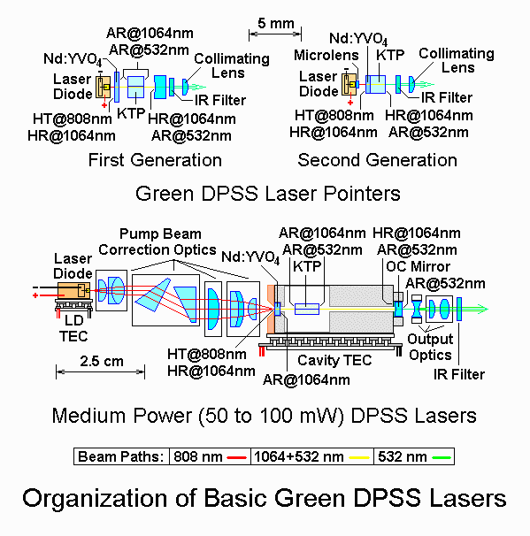
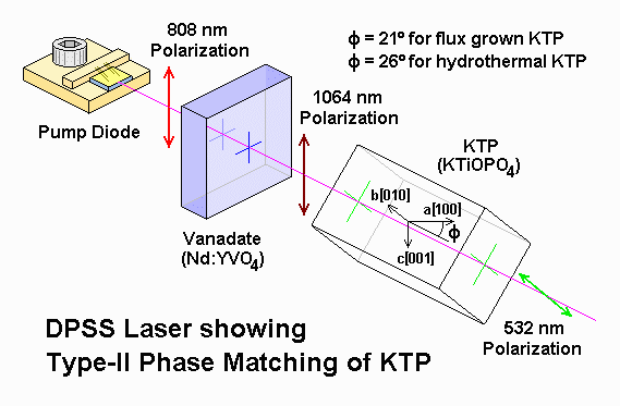
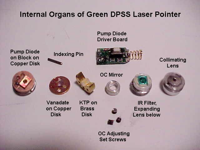
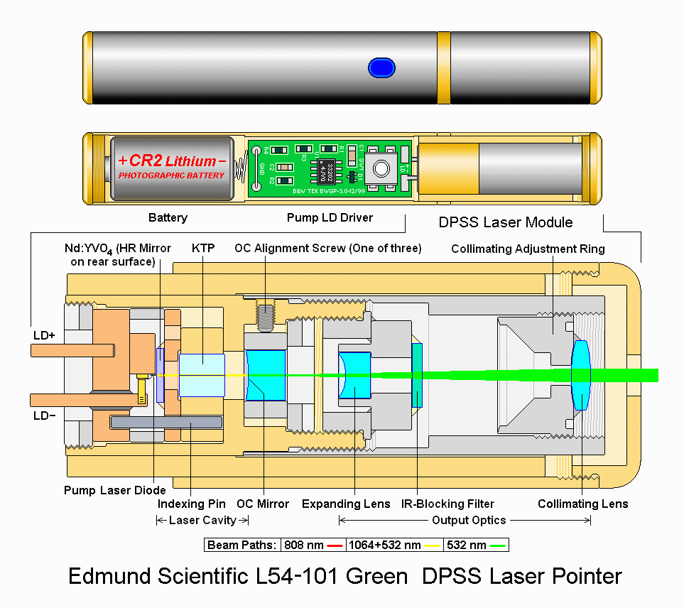
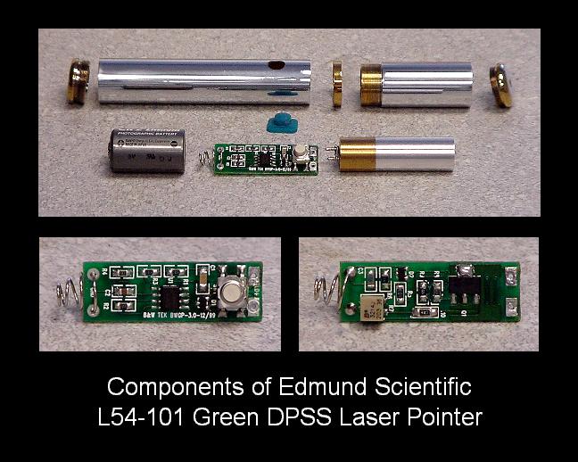
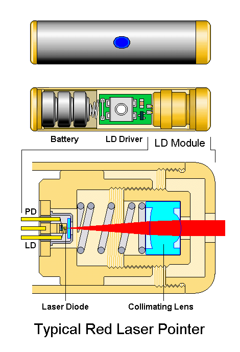
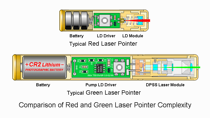
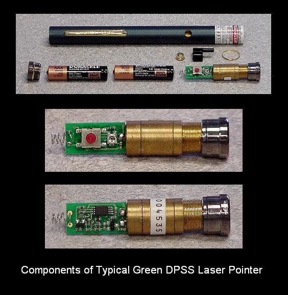
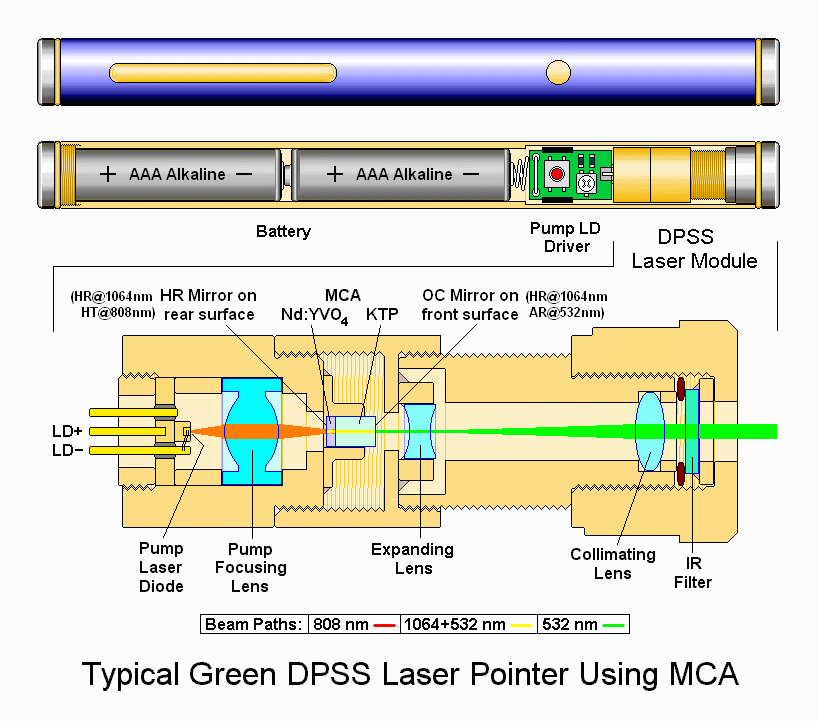
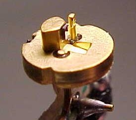
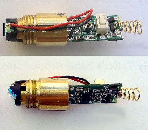
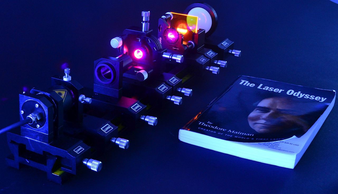