Diode lasers use nearly microscopic chips of Gallium-Arsenide or other exotic semiconductors to generate coherent light in a very small package. The energy level differences between the conduction and valence band electrons in these semiconductors are what provide the mechanism for laser action. This is not the sort of laser you can build from scratch in your basement as the required fabrication technology costs megabucks or more to set up. You will have to be content with powering a commercial laser diode from a home-made driver circuit or using a pre-packaged module like a laser pointer. Fortunately, laser diodes are now quite inexpensive (with prices dropping as you read this) and widely available.
The active element is a solid state device not all that different from an LED. The first of these were developed quite early in the history of lasers but it wasn't until the early 1980s that they became widely available - and their price dropped accordingly. Now, there are a wide variety - some emitting many *watts* of optical power. The most common types found in popular devices like CD players and laser pointers have a maximum output in the 3 to 5 mW range.
A typical configuration for a common low power edge emitting laser diode is shown below:
                          +                                     +
                          o                                     o
            ______________|______________                _______|_______
     Laser |   P type semiconductor      |  Laser       |     P type    |
      beam |                             |  beam        |               |
   <=======|:::::::::::::::::::::::::::::|=======>      |ooooooooooooooo|
           |        Junction---^         |              |               |
     End ->|   N type semiconductor      |<- End        |     N type    |
   facet   |_____________________________|   facet      |_______________|
                          |                                     |
                          o                                     o
                          -                                     -

                     (Side view)                            (End view)

          |<----------------------- 1 mm ------------------------>|
This configuration above is called a 'homojunction' since there is only one P-N junction. It turns out there are benefits to using several closely spaced junctions formed by the use of layers of P and N type materials. These are called 'heterojunction' laser diodes. There are many many more advanced structures in use today and new ones are being developed as you read this! For example, see the section: Vertical Cavity Surface Emitting Laser Diodes (VCSELs) for a description of one type that has the potential to have a dramatic impact in many areas of technology.
The 'end facets' are the mirrors that form the diode laser's resonant cavity. These may just be the cleaved surfaces of the semiconductor crystal or may be optically ground, polished, and coated.
For these types of integrated laser diodes, everything takes place inside the chip. Therefore, the output wavelength is fixed and determined by the properties of the semiconductor material and the device's physical structure. Or, at least that's the way it is supposed to work though with some, reflection of the laser light back into the chip can cause stability problems or even be used to advantage to frequency stabilize the output. There are also tunable diode lasers using external cavity optics to provide a continuous and in some cases, quite wide range of wavelengths without mode hopping.
There are also pulsed laser diodes requiring many amps to to reach threshold and providing watts of output power but only for a short time - microseconds or less. Average power is perhaps a few mW. These are gallium arsenide (GaAs) heterojunction laser diodes. They are not that common today but some surplus places are selling diodes like these as part of the Chieftain tank rangefinder assembly. They mention the high peak power output but not the low average power. :( Modern devices with similar specifications are also available from manufacturers like OSRAM Opto Semiconductors. Go to "Products", "High Power Laser Diodes", "Product Catalog...", "Pulsed Laser Diodes in Plastic Packages".
Electrical input to the laser diode may be provided by a special current controlled DC power supply or from a driver which may modulate or pulse it at potentially very high data rates for use in fiber optic or free-space communications. Multi-GHz transmission bandwidth is possible using readily available integrated driver chips.
However, unlike LEDs, laser diodes require much greater care in their drive electronics or else they *will* die - instantly. There is a maximum current which must not be exceeded for even a microsecond - and this depends on the particular device as well as junction temperature. In other words, it is not sufficient in most cases to look up the specifications in a databook and just use a constant current power supply. This sensitivity to overcurrent is due to the very large amount of positive feedback which is present when the laser diode is lasing. Damage to the end facets (mirrors) can occur very nearly instantaneously from the concentrated E/M fields in the laser beam. Closed loop regulation using optical feedback to stabilize beam power is usually implemented to compensate for device and temperature variations. See the sections on CD and visible laser diodes later in this document before attempting to power or even handle them. Not all devices appear to be equally sensitive to minor abuse but it pays to err on the side of caution (from the points of view of both your pocketbook and ego!).
In their favor, laser diodes are very compact - the active element is about the size of a grain of sand, low power (and low voltage), relatively efficient (especially compared to the gas lasers they replaced), rugged, and long lived if treated properly.
In fact, high power laser diodes - those outputting WATTs of optical power - are without a doubt the most efficient light emitter - not just lasers - in existence. Some have electrical to optical efficiencies (DC W in to light W out) of greater than 50 percent! In other words, put 2 watts of DC power in and get out 1 W of light. And, research is in progress to improve this to 80 percent or beyond. The common incandescent lamp is only 5 percent, fluorescent lamps are 15 or 20 percent efficient, high intensity discharge lamps are somewhat better, but even the best can't match the laser diodes in existence now. Just think: If those super high efficiency high power laser diodes could be mass produced in visible wavelengths and were used to replace all light bulbs, the World's electicity usage would be cut way down, not to mention hobbyist access to high power lasers! (Which is of much more significance!) OK, back to reality. :)
Laser diodes do have some disadvantages in addition to the critical drive requirements. Optical performance is usually not equal to that of other laser types. In particular, the coherence length and monochromicity of some types are likely to be inferior. This is not surprising considering that the laser cavity is a fraction of a mm in length formed by the junction of the III-V semiconductor between cleaved faces. Compare this to even the smallest common HeNe laser tubes with about a 10 cm cavity. Thus, these laser diodes would not be suitable light sources for high quality holography or long baseline interferometry. But, apparently, even a $8.95 laser pointer may work well enough to experiment in these areas and some results can be surprisingly good despite the general opinion of laser diode performance.
Even if not as good as a helium-neon laser in the areas of coherence and stability, for many applications, laser diodes are perfectly adequate and their advantages - especially small size, low power, and low cost - far outweigh any faults. In fact, these 'faults' can prove to be advantageous where the laser diode is being used simply as an illumination source as unwanted speckle and interference effects are greatly reduced.
As noted, not all laser diodes have the same performance. See the section: Interferometers Using Inexpensive Laser Diodes for comments that suggest some common types may indeed have beam characteristics comparable to typical HeNe lasers. And, for short range applications, see: Can I Use the Pickup from a CD Player or CDROM Drive for Interferometry?. Also see the section: Holography Using Cheap Diode Lasers.
The following sites provide some relatively easy to follow discussions of the principles of operation, construction, characteristics, and other aspects of laser diode technology:
Here's a link to a historical look at the early days of laser diodes:
The closeups below were scanned at 600 dpi - laser diodes (at least the small ones we are dealing with) are really not this HUGE! These two laser diodes can also be found in the group photo, above.
The Closeup of laser diode from the Sony KSS361A Optical Pickup shows a type that is found in many CD players and CDROM drives manufactured by Sony. The actual laser diode is inside the brass barrel shown in the photo of the optical pickup. The front of the package is angled so that the exit window (anti-reflection coated) is also mounted at angle to prevent any remaining reflections from the window's surfaces - as small as the are - from feeding back into the laser diode's cavity or interfering with the detected signal. The output of these edge emitting laser diodes is polarized. See the section: What is a Brewster window?.)
The Closeup of Typical Laser Diode shows one that is from a laser printer. It was mounted in a massive module (relative to the size of this laser diode, at least) which included the objective lens and provided the very important heat sink. In some high performance laser printers, a solid state Peltier cooler is used to stabilize the temperature of the laser diode. The low power laser diodes in CD and LD players, and CDROM and other optical drives (at least read-only types) get away with at most, the heat sink provided by the casting of the optical block - and many don't even need this being of all plastic construction.
One can think of an LED as a laser without a feedback cavity. The LED emits photons from recombining electrons. It has a very broad spectrum.
When we add a high Q cavity to it, the feedback can be high enough to trigger true laser action. Most laser diodes have the cavity built right into the device but there are such things as external cavity diode lasers.
The addition of the high Q cavity cuts down drastically the number of modes operating (in fact, it is almost improper to speak of mode structure with an LED. The result is that the emission line narrows drastically (more monochromatic) and the beam narrows somewhat spatially. One can still not easily get true single mode lasing with normal diode lasers, however, so the line will not be as sharp as a gas laser, nor the beam as narrow.
For more info, see the section: How LEDs Compare to Laser Diodes - Wavelengths, Spectrum, Power, Focus, Safety.
(From: Don Stauffer (stauffer@htc.honeywell.com).)
Yes indeed, a diode laser is a true laser. That being said, looking at matters quantitatively, it is harder to make a diode laser with a very narrow line emission than a gas laser or large crystal laser. Adding cavity length to a laser in general acts to narrow the line (in spectral space, though a higher Q cavity does tend to narrow beam in space also). It is possible to use a larger, high Q external cavity with a laser diode to increase its coherence.
(From: David Schaafsma (drdave@jnpcs.com) and Rajiv Agarwal (agarca@giascl01.vsnl.net.in).)
A couple of minor points:
High Q cavities narrow the spatial profile only if they are confocal - planar high Q cavities (as in diode lasers, and especially vertical-cavity diode lasers) are prone to problems with walk-off and the mode must be confined physically.
In a gas laser, you also start with a much narrower fluorescence line and thus the gain spectrum is limited spectrally. Diode lasers (being band-to-band or excitonic semiconductor transitions) have much broader fluorescence spectra.
The typical edge-emitting diode laser actually lases in quite a few fundamental modes (especially when operated using its own facets as the cavity) and though each lasing mode is "monochromatic", the overall spectrum really isn't. External cavities are really the only way to obtain approximately single mode operation from an edge-emitting diode laser.
VCSELs are usually true single mode devices. The reason you can get away with lengthening the cavity in a gas laser is that you don't need to worry about lowering the free spectral range because the gain bandwidth is small.
DFB or DBR lasers achieve very similar results and have Side mode suppression ratios better than 30 db. These lasers have been the mainstay of Optical fiber base telecom for a while now.
DFB Lasers are use for long haul telecommunications network - the kind used by say Sprint (>1GB for up to 25 miles) for their phone networks between cities. These have been for Trans-Atlantic cables (TAT) between US and Europe. LEDs are used more for FDDI type application between computers (~100Mb and less than 1 mile).
(From: Vishwa Narayan (vishwa.narayan@ericsson.com).)
While LEDs are quite popular in Datacom applications (read short distances), Telecom applications typically use DFBs, either directly modulated for low speeds (e.g., OC-3 155 Mb/sec) or externally modulated for high speeds (e.g., OC-48 2.5 Gb/sec). Distances can typically range over tens of kilometers, to hundreds of kilometers with optical amplification, sans repeaters.
One should never look into the beam of any laser - especially if it is collimated. Use an indirect means of determining proper operation such as projecting the beam onto a white card, using an IR detector card or tester (where needed), or laser power meter.
Currently, green laser pointers are not simple diode lasers but are Diode Pumped Solid State Frequency Doubled (DPSSFD) lasers (this may change in the future, however). For a given power, green appears substantially brighter than red wavelengths but are also limited a maximum power of 5 mW. However, since there is a high power IR laser diode inside a green pointer and not all include an adequate IR-blocking filter, there could be other dangers lurking even if the green output is weak or dead.
(From: Gregory Makhov (lsdi@gate.net).)
According to a recent report by Dr. David Sliney, who is one of the leading "gurus" of laser safety, there are no confirmed accidents or injuries caused by laser pointer of 5 milliwatts radiant power or less. There is an awful lot of nonsense and false claims about this. Pointers are extremely bright, can cause visual distraction, afterimages, and other effects, such as headaches, but under most any typical usage condition, DO NOT cause eye injury. Dr. Sliney works for US Army, and has published papers and books on laser safety for over 20 years.
With both of these, the beam from the bare laser diode is highly divergent and therefore less of a hazard since the lens of the eye cannot focus it to a small spot. However, there is still no reason to look into the beam.
With these high power laser diodes, even the divergent beam from the bare device is a definite hazard at close range. Where there are collimating optics (even an almost invisible microlens), the result is a mostly or totally invisible beam that can be dangerous to vision from direct exposure and specular reflection at distances of several feet. These are particularly scary especially for people who have become complacent about diode laser safety due to their expectation of a widely diverging beam.
For IR laser diodes in particular, especially if you are considering selling a product:
(Portions from: Steve Roberts.)
You need to take a close look at the CDRH rules, because there is no blink reflex in the IR. IR diode lasers are considered much more dangerous and therefore are in a higher class. CDRH has a curve of power versus wavelength that is used for determining safety classes. The only way a IR laser gets less then a IIIb rating (read: dangerous) is if the beam is totally enclosed or of very low power. Go to CDRH, call them and request a manufacturers' packet by mail. It's huge and confusing, but covers the requirements for products using IR laser diodes such as 3-D scanners, perimeter sensors, and so forth.
Visible laser diodes have replaced helium-neon lasers in supermarket checkout UPC scanners and other bar code scanners, laser pointers, patient positioning devices in medicine (i.e., CT and MRI scanners, radiation treatment planning systems), and many other applications. The first visible laser diodes emitted at a wavelength of around 670 nm in the deep red part of the spectrum. More recently, 650 nm and 635 nm red laser diodes have dropped in price.
Due to the nonuniformity of the human eye's response, light at 635 nm appears more than 4 times brighter than the same power at 670 nm. Thus, the newest laser pointers and other devices benefitting from visibility are using these newer technology devices. Currently, they are substantially more expensive than those emitting at 670 nm but that will change as DVDs become popular:
Laser diodes in the 635 to 650 nm range will be used in the much hyped DVD (Digital Video - or Versatile - Disc) technology, destined to replace CDs and CDROMs in the next few years. The shorter wavelength compared to 780 nm is one of several improvements that enable DVDs to store about 8 times (or more - 4 to 5 GB per layer, the specifications allow up to 2 layers on each side of a CD-size disc!) the amount of information or video/audio as CDs (650 MB). A side benefit is that dead DVD players and DVDROM drives (I cannot wait) will yield very nice visible laser diodes for the experimenter. :-)
Like their IR cousins, the typical maximum power from these devices is around 3 to 5 mW. Cost is in the $10 to $50 for the basic laser diode device - more with optics and drive electronics. Higher power types (10s of mW) are also available but expect to spend several hundred dollars for something like a 20 mW module. Very high power diode lasers using arrays of laser diodes or laser diode bars with power output of WATTs or greater may cost 10s of thousands of dollars!
                ___
               |   |          Metal case
               |   |_______________________________
               |                                   \
               |    _____________________________   |
               |   |                             |  |
     LD -------:===:------------------+          |  |
               |   |__                |          |__|
               |   |  |___      ______|______    :  :
               |   |  |   |    |             |   :  :
     PD -------:===:----+ |<---|:::::::::::::|============> Main beam
               |   |  |___|____|_____________|_  :  :          (divergent)
               |   | Photodiode  Laser diode   | :__:
               |   |\__________________________| |  | Protective window
    Com -------+   |          Heat sink          |  |
               |   |_____________________________|  |
               |                                    |
               |    _______________________________/
               |   |
               |___|
The main beam as it emerges from the laser diode is wedge shaped and highly
divergent (unlike a helium-neon laser) with a typical spread of 10 by 30
degrees. External optics are required to produce anything approaching a
parallel (collimated) beam. A simple (spherical) short focal length convex
lens will work reasonably well for this purpose but diode laser modules and
laser pointers might use a lens where at least one surface is aspheric (not
ground to a spherical shape as are with most common lenses).
In the case of a sample I removed from a dead diode laser module, the surface facing the laser diode was slightly curved and aspheric while the other surface was highly curved and spherical. The effective focal length of the lens was about 5 mm. It appeared similar to the objective lens of a CD player - which was perhaps its original intended application and thus a low cost source for such optics.
Due to the nature of the emitting junction which results in a wedge shaped beam and unequal divergence (10 x 30 degrees typical), a laser diode is somewhat astigmatic. In effect, the focal length required to collimate the beam in X and Y differs very slightly. Thus, an additional cylindrical lens or a single lens with an astigmatic curvature is required to fully compensate for this characteristic. However, the amount of astigmatism is usually small and can often be ignored. The general beam shape is elliptical or rectangular but this can be circularized by a pair of prisms.
The light from these edge emitting laser diodes is generally linearly polarized. You can easily confirm this even with a simple laser pointer by reflecting at about a 45 degree angle from a piece of glass (not a metal coated mirror). Rotate the pointer and watch the reflection - there will be a very distinct minimum and maximum with the elongated shape of the beam at close range being aligned with the glass and perpendicular, respectively. For the advanced course, determine the Brewster angle. :)
For addition information, see the section: Beam Characteristics of Laser Diodes.
The beam from the back end of the laser diode chip hits a built-in photodiode which is normally used in an opto-lectronic feedback loop to regulate current and thus beam power. Note that the photodiode is likely mounted at an angle (not possible to show in ASCII) so that the reflection does not interfere with the operation of the laser diode.
CAUTION: Some complete modules may use the reflection from external optics along with an external photodiode for power stabilization as it is more accurate since the actual output beam is sampled. For these, one should never attempt to clean or even focus the lens when operating near full power as this may disturb the feedback loop and damage the laser diode.
Note: Some of the symbols below are not exactly what is found in the datasheet so they can be represented in ASCII. However, the meaning should be obvious.
       Parameter        Symbol       Conditions        Min   Typ.   Max   Unit
 ------------------------------------------------------------------------------
  Threshold current      Ith                                  30     40    mA
  Operating current      Iop          Po = 5mW                35     45    mA
  Operating voltage      Vop          Po = 5mW               2.2    2.4    V
  Wavelength           lambdap        Po = 5mW               650    660    nm
  Radiation angle
    Perpendicular      theta_|_       Po = 5mW         22     30     40   Deg.
    Parallel           theta||        Po = 5mW          5      7     12   Deg.
  Positional accuracy  dx,dy,dz       Po = 5mW                     +/-150  um
  Angular accuracy
    Perpendicular       phi_|_        Po = 5mW                      +/-3  Deg.
    Parallel            phi||         Po = 5mW                      +/-3  Deg.
  Differential eff.      nD           Po = 5mW        0.3    0.6    0.9  mW/mA
  Astigmatism            As           Po = 5mW                 7     15    um
  Monitor PD current    Imon     Po = 5mW, Vr = 5V    0.05   0.1    0.25   mA
Descriptions of the parameters are provided below:
"I was just browsing Meredith Instrument's site, and noticed that they have 635 nm diodes rated at 500 mW. Has anyone ever dealt with these things? Looking around on the site, it appears I could put together a half watt red diode laser for under $600, or a 250 mW one for under $400. Is there some catch to using these? The whole setup would be cheaper than a 25 mW HeNe laser".
Yes. Aside from the ease with which one of those pricey diodes can be blown out due to improper drive, the beam quality is no where near that of even a cheap HeNe laser. It is multimode and very non-circular and astigmatic. The latter can probably be dealt with using some (expensive) optics. However, multimode operation means that these are unsuitable for applications like holograpy or interferometry.
(From: Frank DeFreitas (director@holoworld.com).)
I have a 500 mW laser diode from Polaroid. 660nm I believe. It needs the heftier driver that Meredith offers - the one that can put out 1000 mA or so. The laser diode is gain guided/multi-mode, rather than index guided/single (mono) mode -- so you can pretty much forget any application that would call for any type of coherency or high contrast fringes.
The output beam profile is basically a line. It is very similar to taking a standard HeNe beam and sending it through a cylindrical lens. (However, on the other hand, I'm wondering if a cylindrical lens would actually help it when used in the other dimension. Or at least bring it to a spot which could be collimated utilizing secondary optics in the path.)
I'd also like to point out that it's not a diode to play around with. The optical output at 500 mW is not going to knock any missiles out of the sky, but will certainly warrant caution when working with the beam. The beam is much more powerful than it appears at 660 nm due to the eye's reduced sensitivity at that wavelength compared to HeNe 632.8 nm.
These modules have been turning up new/NOS surplus in 2017, presumably after Melles Griot discontinued the 85-BTA/BTC/BTL lasers. They are easily driven with commercial laser diode drivers and TEC controllers like the ILX Lightwave (now Newport) LDC-3900. The typical threshold is around 400 mA and the typical slope efficiency is around 1.04 mW/mA. For reference, here are the pinouts for the 7 pin header/connector and TO3 package.
   Header   Wire
    Pin     Color  TO3 Pin   Function
  ------------------------------------------------------------------------
     1      Gray      4      Laser diode cathode
     2      White    5,7     Laser diode anode/monitor photodiode cathode
     3     Yellow     3      Thermistor 2
     4      Blue      2      Thermistor 1
     5       Red      1      TEC+
     6      Black     8      TEC-
     7     Orange     6      Monitor photodiode anode
Even at maximum rated output of 500 mW, the total device dissipation is low so only minimal additional heat sinking is needed for continuous operation.
CAUTION: There may not be any internal ESD or reverse polarity protection so handle carefully once the shorting connector (if present) is removed.
About those laser diode bars:
(From: Walter Skrlac (Walter.Skrlac@t-online.de).)
"Bars are a 10 mm wide chip with typically 16 to 24 emitters, each emitter being about 150 microns wide and emitting up to 2 watts of power per emitter. The highest power for solid state laser pumping is 40 watts from a 19 emitter bar. Almost all bars are a single chip, multiple emitter device. I do know that in the beginning days of bars, Siemens produced a 5 watt device consisting of 5 separate 1 watt laser diodes mounted in a row 10 mm long. The individual laser diodes are connected in parallel so you can't switch them individually."
The good news is that this technology is developing very rapidly.
The bad news from our perspective is that there are no really low cost sources, new or surplus, for these diode lasers as far as I know at the present time. However, prices have been dropping rapidly since this was first written. The cost of 1 W 808 nm laser diodes has dropped below $100 new, and with luck, much cheaper from surplus sources and on eBay.
Actually, it isn't necessarily the diode itself that is so expensive. A 1.5 W 800 nm diode chip goes for about $10 when they are purchased in reasonably large quantities. However, these are only about 0.5 mm on a side and maybe 0.1 mm thick. Mounting means using low temperature solder and flux to bond the chip to a large heat sink and copper strip (for the two connections - no monitor photodiode, that function must be performed externally). The soldering is best done on a hot plate (to raise the temperature of the heat sink and chip to almost the melting point of the solder), with a fine tip iron for the last few degrees. They have an HR and OC side, and a top and bottom, and thus orientation matters. So, if you have access to a surface mount rework station with a stereo microscope, a steady hand, infinite patience, and don't sneeze much (which will blow your chips away to never be found again), you could try your hand at the mounting. I have a couple of these diode chips so once I get up the nerve to try this, I will report on success or failure.
The better way to deal with these laser diodes is to have them already mounted on a heat sink. But now we're talking about $100s for a single unit. But, for a number of reasons, the best type of high power laser diode to get is probably a fiber-coupled module. Then you don't have to mess with beam shape issues, the diode is safely tucked away out of harm, and the fiber output can easily be adapted to your favorite crystal shape. Some power is lost in the coupling but it appears as though the specs I've seen are similar for the bare diode assembly and fiber-coupled module. Of course, the cost for such a module now appoaches that of a nicely equipped PC. :) For more info, see the section: Anatomy of Fiber-Coupled Laser Diodes.
Laser diode bars/assemblies of much higher power are available - up to the kW range and beyond. Of course, the prices go up as well. Check out CEO Laser as one possible supplier. They have a wide variety of really interesting items but unfortunately without any prices. Bars can be connected in series to ease the power supply requirements enabling them to be driven with lower current at higher voltage (e.g., a 4 bar configuration would use 8 V at 50 A instead of 2 V at 200 A). With individual chips on a common heat sink, this really isn't an option.
Note that most high power diode lasers are near IR - often around 800 nm for pumping DPSS lasers or 830 to 870 nm for thermal platesetters. High power visible laser diodes are much less common and usually limited to less than a watt at 670 nm. Not that this is terrible. :)
If you have your heart set on one of these for your birthday, all I can suggest at the present time is to keep track of what is available surplus and to check with the manufacturers listed in the chapter: Laser and Parts Sources. They do show up on eBay but accuracy of the description and operating conditoin may be unknown. If this is for some sort of academic project with a legitimate research objective, you may be able to obtain a cosmetic reject or one that doesn't quite meet specs by persistent pleading with one of the laser diode manufacturers. Or, if you can deal with the bare chips, it may be possible to beg a few from one of the companies that produces DPSS laser systems since they use them by the carload, and when purchased by the carload, the cost goes way down.
Keep in mind that obtaining the diode is only a small part of the problem. To drive them reliably, particularly near their maximum power rating, will require a suitable constant current laser diode driver and proper cooling. However, if reasonable precautions are taken and they aren't run near their maximum ratings, actually blowing them out totally isn't nearly as easy as with their low power counterparts.
And, needless to say, at these power levels, your eyes (and flammable objects) don't get a second chance - laser safety must be at the top of your list of priorities.
These laser diodes come in plastic packages that look much like LEDs and thus there is no real possibility of decent cooling. Therefore, power dissipation is one of the major limiting factors. It may be possible to use a lower peak current with a longer pulse width than what's specified in the datasheet as long as the average power dissipation rating isn't exceeded. However, with the high threshold current, this probably doesn't provide much benefit. And, no guarantees of any kind with laser diodes!
There is some info on driver circuits for pulsed laser diodes in the section: Pulsed Laser Diode Drivers.
The following assumes a device rated at 16 W peak power, 100 ns max pulse width, 0.1% max duty cycle:
(From: Roithner Lasertechnik" (office@roithner-laser.com).)
The absolute limit is the heat stress of the LD chip inside. Under normal conditions, the laser will emit a pulse of the rated 16 W, 100 ns at 10 kHz (200 ns at 5 kHz is the absolute limit) - which is highly recommended for an expected long lifetime of several khours with usual chip degradation. Take this integrated V x I (voltage x current) thermal heat stress as a final constant. If you run with a higher frequency than the rated, but with a shorter pulse width, still never go higher than this constant. If you go higher, the laser pulse power will go down rapidly due to overheating of the LD chip (still reversible, LD is not yet blown) but overall lifetime is shortened. Keep in mind, that the rise and fall time of this LD is typically 1 ns, so you will get the next limit soon.
VCSELs, on the other hand, emit their beam from their top surface (and potentially bottom surface as well). The cavity is formed of a hundred or more layers consisting of mirrors and active laser semiconductor all formed epitaxially on a bulk (inactive) substrate.
This approach provides several very significant technical advantages:
The beam from a typical VCSEL exits from a circular region 5 to 25 um in diameter. Since this is much larger than for the FP laser diode, the divergence of the resulting beam is much lower. And, because it is also circular, no corrections for asymmetry and astigmatism are required - a simple lens should be able to provide excellent collimation.
There are also numerous manufacturing and cost advantages:
On the other hand, an entire wafer of VCSELs can be tested as a unit with each device evaluated for lasing threshold and power, and beam shape, quality, and stability, It is possible to form millions of VCSELs on a single wafer as a batch process and then test and evaluate the performance of each one automatically. The entire wafer can be burned in to eliminate infant mortalities and assure higher reliability of the final product. Each device can then be packaged or thrown away based on these findings.
VCSEL technology is in its infancy and its potential is just beginning to be exploited. Quite possibly, VCSELs will become the dominant type of laser diode in the future with capabilities so fantastic and costs so low as to be unimaginable today. There is some technical information at the following sites:
For a general review article, see: "The Ideal Light source for Datanets", K.S. Giboney, L.B. Aronson, B.E. Lemoff, IEEE Spectrum V.35 (2) p. 43, Feb 1998.
If you want to play with VCSELs, bare chips, packaged chips, and even VCSEL arrays are available from various laser suppliers and prices aren't totally rediculous. For example, see Roithner Lasertechnik's VCSEL Page. Available wavelengths are currently 780, 850, 980 nm, but wavelengths beyond 1,300 nm are available from other suppliers and the range is being extended in both directions.
If you suspect that one of your laser diodes might be a VCSEL without admitting it, just check the raw beam pattern. The output of a VCSEL will be fairly symmetric while that of an edge emitting laser will typically have a 4:1 angular spread as discussed above.
There is also something called a "Resonant Cavity LED", which in essence places an LED junction between mirrors. Some of these efforts result in stimulated emission with the appearance of a longitudinal mode structure, but not enough gain to reach lasing threshold. However, I'm not sure if these structures differ from VCSELs in any fundamental way. See, for example: Stimulated Emission from InGaN-Based Resonant Cavity Light Emitting Diodes.
The optical architecture is quite simple: An edge-emitting laser diode, collimating lens, steep-angle reflective grating, turning mirror, Brewster or polarizing plate, another mirror or perpendicular plate at the output, and an AR-coated window.
Here are some photos:
The orientation for the following two photos has been rotated 180 degrees. This violates may "laser beams must always exit toward the right" rule but it makes the text on the PCB come out the right way up. :)
I've tested both a fully functional 445 nm laser and mostly dead 780 nm laser (the latter being the one in the photos). Powering the laser is quite straightforward. Referring to the photo of the connector above or the label on the laser, GND to pin 8, +5 VDC to pin 7, and an output power control voltage to pin 6. Between 0 and 5 V, the output increases though it is not known how linear the relationship is. Above 5 V, it increases further but on this sample, the laser shuts down at not much over 5 V. I've heard that others will increase up to at least 6 V without shutting down. It's possible this behavior depends on hitting the internal current limit for the laser diode. Pin 5 is a power monitor output which for the 445 nm version seemed to track at about 20 mW/V.
The laser remains SLM over the entire range of output power, though the modes do move around as power is changed, similar to any other laser. Whether it is actually single frequency or close to it is not clear. My Scanning Fabry-Perot Interferometer (SFPI) doesn't have enough resolution to be resolve any really closely spaced modes, though there is a hint that they may be present. It is very sensitive to back-reflections, as would be expected of any stabilized laser, and especially a stabilized diode laser. The output is linearly polarized, though it is not very pure. It was speculated that the angled plate and output optic formed some sort of optical isolator. For example if the angled plate was a polarizer and the perpendicular plate was a QWP, the result would be a "poor man's optical isolator". If so, it's not very effective. Of course if this is an ECDL, then the Brewster plate may be to help force linear polarization with the perpendicular plate being the OC mirror. But its thickness was like that of the turning mirror, not like that of a typical high quality cavity mirror.
The 780 nm laser did emit a beam even without the mystery plate near the output, but it was way below 1 µW. It is not known if that was simply LED emission from an LD without an output mirror, or just a very weak beam.
Now, if all the light bulbs in the World were replaced with these high efficiency laser diodes mass produced in visible wavelengths, the the energy crisis - at least with respect to electrical generating and transmission capacity - would be over (or at least greatly reduced as a here and now crisis), since it's been estimated that 50 percent of electricity usage goes into lighting and most of this is presently highly inefficient. Incandescent lamps are only about 5 percent efficient; halogen lamps around 7 to 10 percent; and fluorescents, about 15 to 20 percent. High brightness LEDS suitable for lighting applications are advancing but are currently somewhere around halogen lamps in efficiency (though under some conditions, LEDs at low power may exceed 25 percent efficiency). But, it's unlikely that the LED could even match the laser diode due to the basic physics.
A side benefit of mass produced laser light bulbs might be that hobbyists' access to high power lasers would be greatly improved! :)
Before you say that it would be too dangerous to have every table lamp using a high power laser, it would be a relatively simple matter to mold a diffuser onto the laser diode in such a way that it would be virtually impossible to disassemble (sorry hobbyists but maybe if we lobby hard enough, a special tool could be made available!) and then wouldn't be any more dangerous than a common light bulb.
Aside from reducing the cost of high power laser diodes by about 3 or 4 orders of magnitude, wavelength is a definite stumbling block that still needs to be overcome before any of this could be practical. Either red, green, and blue laser diodes will need to be combined in a single lamp assembly to produce something approaching white light or a combination of high efficiency phosphors will be needed to convert near-UV to visible light. One can envision a lighting panel in standard sizes like 2x2 or 2x4 feet that replaced fluorescent ceiling fixtures but used less than 25 percent of their power. Or, CLLs (Compact Laser Lamps) that replaced incandescent or compact fluorescent lamps. Needless to say, high power multicolor or UV laser diodes do not presently exist but a market measured in billions of units compared to current usage of 10s of thousands could provide a lot of incentive to develop them! :)
As of 2013, lasers for illumination have already made it into several mainstream applications. Three of them are:
In particular:
See the section: On-Line Introduction to Lasers for the current status and on-line links to these courses, and additional CORD LEOT modules and other courses relevant to the theory, construction, and power supplies for these and other types of lasers.
Several modules would be of particular interest for diode lasers. Unfortunately, the on-line manuals (in PDF format) have disappeared from the MEOS Web site. But I have found and archived most of them:
If MEOS should complain, these will have to be removed. So, get them while you can! But I doubt they'll complain. And most are also archived at the Wayback Machine Web Site.
Some very good basic information about laser diodes is provided in of all places, manufacturer's catalogs! :) Try companies like Mitsubishi, Fujitsu, Hitachi, Sharp, Sony, NEC, etc. They have introductory sections at the front or the back of their laser diode catalogs. Just call the and ask for a laser diode catalog. Much of this is now on-line.
The divergence angle (half of total), Theta, (in degrees) is given by:
                               Wavelength * 720
                   Theta = -------------------------
                            pi * pi * Beam Diameter
At a wavelength of 670 nm, this works out to about 48 x 16 degrees for a 1 um x 3 um emitter and 48 x 0.48 degrees for a 1 x 100 um emitter (compared to around 0.05 degrees for a 1 mm diameter beam from a 632.8 nm helium-neon laser). However, since laser diodes with 100 um emitters are always multiple spatial mode, this low value of divergence will never be seen in practice. Such diodes tend to have similar divergence to that of single mode emitters.
Note that since at least one of the dimensions of the end-facet is close to the wavelength that the laser diode emits - it may even be smaller - this simple equation is not very precise but typical low power laser diodes do produce beams with a divergence of around 10 x 30 degrees.
Laser diode divergence will generally be given in terms of the Full Width Half Maximum (FWHM) in terms of output power, or "T full width". At the 10% level, this may be more like 70 or 80 degrees than the 30 degrees in the specifications.
For more information (and some medium weight math) on the beam characteristics of common laser diodes, check the Power Technology, Inc. Go to "Resource Library", "White Papers".
There are ways of correcting for all of these artifacts with a single special lens close to the laser diode itself. For example, Blue Sky Research offers combined laser diodes and microlenses which they claim perform as well as larger more expensive diode laser modules using various discrete lenses and prisms to implement the beam correction.
Note that VCSEL (Vertical Cavity Surface Emitting Laser diodes) need not suffer from astigmatism and/or an elliptical beam profile since their emitting aperture can be made to be perfectly symmetrical. I would also expect them not to need to be polarized for this reason as well. See the section: Vertical Cavity Surface Emitting Laser Diodes (VCSELs).
At Philips we used three difference techniques to measure astigmatism in laser diodes:
Without any type of correction, the output of a bare laser diode is more like that from a mediocre flashlight than what is normally thought of as a laser source. Some optics are needed to produce a reasonably well collimated beam (like the one from a cheap laser pointer) and more sophisticated optics are needed to provide optimal beam quality (which can be very good indeed). Of course, depending on the particular application, one or more of these so called 'defects' may actually be considered desirable.
An alternative technique, apparently used in many optical pickups, is to pass the beam through a thick optical plate having parallel sides at an angle (actually combined with the 45 degree beamsplitter mirror when used for this application). This component has a very significant astigmatic effect whose magnitude is easily controlled by selecting the thickness or adjusting the angle of the plate. In the optical pickup, it is used to add astigmatism for the focusing servo but can just as easily be used to eliminate it. See the document: Notes on the Troubleshooting and Repair of Compact Disc Players and CDROM Drives for more information on optical pickup characteristics.
Still another approach which will correct for the elliptical beam profile and astigmatism all at once is to couple the beam into a single mode optical fiber using two short focal length lenses. With a sufficiently long fiber (well, relative to the wavelength), the output beam characteristics will be entirely determined by the quality of the output face of the fiber. Then, a simple collimating lens can be used.
Whatever type of external optics are added, take care that significant power isn't reflected back into the laser diode itself. This can destabilize the lasing process as well as fooling the built-in photodiode into thinking the output power is higher than it really is causing the optical feedback circuit to reduce it.
Some additional comments are provided below:
(Portions from: Mark W. Lund (lundm@physc1.byu.edu).)
A simple short focal length lens will collimate the beam. However, laser diodes tend to be astigmatic which means that you will have one axis collimated at a different focus than the other. A typical value for this astigmatism is 40 microns. A cylindrical lens in addition to the spherical collimating lens or a special lens designed for this purpose can correct this but may not be needed for non-critical applications.
Any camera lens will be able to produce a reasonably well collimated beam (subject to the astigmatism mentioned above). Put the laser diode at the focal point of the lens. If you want the type of narrow beam produced by a HeNe laser, you need a short focal length lens, such as a microscope objective. A good compromise between cheap and short focal length would be an old disk camera lens. These cameras can be found at thrift shops, garage or yard sales, and flea markets for a couple dollars or less.
The longer the focal length the larger your beam will be, but the less effect the astigmatism will have. The diameter of the beam will be the size of the aperture of the lens (in which case you are throwing away light) or the size of the beam at the distance of one focal length, whichever is less.
(From: Steve Nosko (q10706@email.mot.com).)
One thing to note is that the laser diode actually has two apparent point sources. One for the wide axis of the beam and another for the narrow axis. This means that the lens must be more like two crossed cylindrical lenses with different focal lengths. There are different types of laser diodes with varying degrees of this so that some are easier to to design lenses for. There probably are types, by now, where there aren't two.
I think of it like this (right or wrong). The astigmatism has two components. One is the difference in divergence between the two axes. I think this can be even if there is ONLY one apparent point source. It is just a point source with an oval aperture letting light through. The other is the different apparent point sources for the two axes.
I have tested a Blueskyresearch PS106 (now discontinued but similar to the VPSL-0655-007) which is a 650 nm, 7 mW Circulaser(tm). The beam is indeed nearly perfectly circular with a divergence of about 8 degrees FWHM - less than that of the lower divergence (slow) axis of the typical bare laser diode. For datasheets, go to Blueskyresearch, then "Semiconductor Laser Products".
Aside from the convenience of not having to worry about their funny beam shape, putting a microlens next to the laser diode itself results in much more of the light being used compared with what gets through inexpensive external optics. With the typical collimating lens used in laser pointers and diode laser modules, as much as 40% or more of the light from the diode may be wasted largely due to its high divergence in the fast axis (30 or 40 degrees total at the half power point, perhaps twice this at the 10% point) - a very significant fraction gets blocked by the small aperture of the collimating lens.
One supplier is Creative Technology Lasers. They even have a super miniature collimated diode laser module only 4 mm (less than 1/6th of an inch) in diameter which connects directly to a 3.3 VDC power source. Check out their "LS" series of diode laser modules.
Given the many advantages of this approach, I wouldn't be surprised if it becomes most common for visible laser diodes used for applications like laser pointers and barcode scanners.
So for the fast axis, two lenses will produce a diffraction limited collimated beam. A very short focal length cylindrical lens is placed almost touching the diode to reduce the typical 40 degree divergence of the raw diode to a few degrees. This is usually a very thin rod lens or piece of fiber core. A second conventional lens is then used to control the beam diameter and collimation. Note that to only affect the fast axis, this would also be a cylindrical lens.
For the slow axis, an anamorphic prism pair may be used to expand the beam followed by a lens to collimate it. With care in the design, that second lens can be the same spherical positive lens for both axes. But you can also do it with separate cylindrical lenses. A pair of cylindrical lenses can be used in place of the anamorphic prisms
There are many other ways of doing this. For example, the output of the can have just the initial fast axis correction using a fiber lens and then be coupled directly into a multimode fiber. The output of the fiber core is then used as the source for a projection lens. But there may be annoying variations in granularity or speckle with any bending of the fiber, temperature changes, vibration, etc.
However, this general rule appears not to apply for all laser diodes including those in many common diode laser modules and even cheap ($9.95) laser pointers. These are now being used routinely for experiments in interferometry and even holography. While their stability over time (e.g., wavelength drift and susceptibility to mode hopping) - is probably less than stellar, over the short term, coherence lengths of 20 cm or more are not unusual. This is similar to that of a typical helium-neon laser.
For more on applications that may benefit from long coherence length diode lasers, see the sections: Interferometers Using Inexpensive Laser DiodesCan I Use the Pickup from a CD Player or CDROM Drive for Interferometry?. Also see the section: Holography Using Cheap Diode Lasers.
(From: Mark W. Lund (mlund@powerstream.com).)
The 1970's grade pulsed laser diodes have coherence lengths of 500 microns or so. Modern CW single mode diodes have coherence lengths of meters. I once asked Don Scifries why they had such long coherence lengths compared to gas lasers with much larger cavities and he referred me some papers. The impression that remains after 13 years is not that laser diodes are so good, but that HeNe Lasers are so bad. Line width of a typical 780 nm CD laser can be 10s of kHz.
(From: Prof Harvey Rutt (h.rutt@ecs.soton.ac.uk).)
**Crudely**, a CW laser will go SLM (Single Longitudinal Mode) spontaneously if the mode separation exceeds the *inhomogeneous* linewidth. The homogeneous linewidth can exceed the mode separation because inter mode competition suppresses the other modes CW. But if mode than mode falls within an inhomogeneous width, and is above threshold, all may oscillate as they do not compete.
The coherence length of a HeNe laser is a simple matter: inhomogeneous linewidth set by Doppler broadening, mode separation set by length, usually a few modes run (or it would power cycle badly) so coherence length is approximately the cavity length divided by number of modes. When it goes single mode (but, unless stabilized, very unstable power output) the coherence length is typically huge. *AND* the absolute frequency is then pretty stable, within half a mode spacing of the atomic line. Simple HeNes are so 'bad' to get reasonable power stability as the cavity length drifts; less than 3 modes->poor.
Most diodes have a pretty broad spontaneous linewidth and how much it is homogeneous or inhomogeneous I'm not clear; possibly as manufacturing has improved the inhomogeneous component has tended to reduce to below the mode spacing? Cavity length is way sub-mm, so as soon as it does twin mode the coherence length is awful.
I have *directly* measured the output spectrum of many near IR diodes, and all bar one set were severely multimode. One set (normal FP lasers) were all single, which surprised me. I think I've only looked at one visible (a while back) and it was heavily multi mode.
When a simple diode does go SLM, surely one might expect it still to have pretty severe wavelength drift with chip temperature? This can certainly wreck holography.
Obviously people have found pragmatically you can get away without an expensive DFB laser; that crude diodes can be SLM; it opens up the interesting qn of just why it seems modern diodes are tending to go SLM spontaneously, & how stable the output wavelength is when they do go SLM (order nm/degree from memory?)
(From: Bret Cannon (bdcannon@owt.com).)
There are two temperature tuning rates for a diode laser, one is the tuning of a given longitudinal mode with temperature and the other is the tuning over larger temperature changes where the lasing mode hope from longitudinal mode to longitudinal mode to be close to the peak of the gain curve. The average tuning rate for this later rate is typically 0.3 nm/°C while for small enough temperature changes the tuning of longitudinal mode is much smaller. For a temperature stability of 1 mK a diode laser frequency is stable to better than 0.001 cm-1, perhaps even a good as 0.0001 cm-1 as determined by tuning onto a Doppler-free atomic transition. Thus at 780 nm the temperature tuning of a longitudinal mode is less than 0.06 nm/°C. With a temperature tuning of less than 1 cm-1/C, a temperature stability of 0.1 °C during an exposure would give a coherence length longer than 10 cm.
Unless there is external optical feedback or a very sophisticated electronic feedback there is no way that a 780 nm CD laser would have a linewidth of 10s of kHz. With a sufficiently low noise current supply (less than 1 microamp RMS in a 1 MHz bandwidth) and temperature stabilization to about 1 mK, the intrinsic linewidth of diode lasers can be measured and they are proportional to the inverse of the output power. Linewidths of about 50 MHz for a 3 mW laser and 5 MHz for a 30 mW laser are typical. These linewidths are 5 to 50 times the Shawlow-Townes linewidth for these lasers and results from the coupling of the refractive index and the population inversion. Moradian (sp?) who was at MIT at the time published experimental measurements in the late 1970s and early 1980s. Henry published an analysis of this line broadening mechanism but I don't remember exactly when.
The linewidth decreases with the square of the cavity length and with external cavities a few cm long people have achieved linewidths of less than 1 kHz. An example of this is work by Leo Holberg and colleagues at NIST in Boulder for an optical clock based on an inter-combination line in optically cooled and trapped atomic calcium.
It depends on the laser diode, the power supply that is used, and the external optical feedback into the diode laser. With a single longitudinal mode diode, without external optical feedback, and a current noise of less than 1 uA RMS in a 1 MHz bandwidth, you can get linewidths of 10 MHz for a coherence time of nanoseconds. With optical feedback the linewidth can collapse to a few Hz or explode to several terahertz, depending on its intensity and the delay time between the light leaving the diode and returning to it.
The wavelength shift for 808 nm diodes is generally around 2.5 nm (+/- 0.2 or 0.3 nm) per 10 °C (or just say 0.3 nm/°C)(, with the wavelength shift to the red (longer) with increasing temperature.
For the violet/blue Nichia laser diodes, it's typically 0.04 nm per °C.
Note that diode current also affect wavelength, partially due to temperature. So, as a diode ages and requires more current for the same output, its wavelength will also change.
(From: Lynn Strickland (stricks760@earthlink.net).)
It really depends on the laser (i.e., manufacturer) and temperature range you are talking about. A good rule of thumb is 0.3 nm per °C over the operating temperature range of the device (About 30 GHz per °C). That's the average slope of the curve though - it includes mode hops. If you're operating at a mode hop, you can get a lot more change than 30 GHz with a 1 °C temperature change. If you are between mode hops, it can be much less.
Mode hops can be a moving target too. Optical feedback can cause them (even minute amounts). Or, you can operate at a specific temperature where there are no mode hops today, but next week it might mode hop at that temperature.
Note that you can only go so far if you want to use temperature to reduce the wavelength. Even if you got the electronics to work under frigid conditions, there is a minimum laser wavelength you can get from a particular diode laser chip. I'm not a physicist, but it has to do with the bandgap of the materials used. What you would get, as you cooled the thing, is lower and lower threshold current, lower operating current, and longer lifetime.
(From: Richard Alexander (pooua@aol.com).)
Back in the old days, about 15 years ago, the only way to get visible light from a laser diode was by using cryogenic cooling. My textbooks from my laser degree program only knows of this type of visible laser diode (they were written in the early '80s). The first room temperature visible laser diode was invented about 1991; I still have a "Radio-Electronics" issue mentioning it.
(From: Flavio Spedalieri (fspedalieri@nightlase.com.au).)
All laser diodes have a tolerance when it comes to wavelength, these tolerances can be as high as +/- 10 nm.
The wavelength tolerances are due to thermal effects, and current. As the diode heats up, the wavelength will change 0.3 nm/°C. and results in mode-hopping.
There are several types of noise in laser diodes: mode hopping as a temperature effect; intensity noise related to spontaneous emission; optical feedback due to reflection in the optics; speckle noise. What you try to control is mode hopping and optical feedback noises.
As temperature varies, shift between modes is an issue but is intrinsic to the LD. By using cooling elements, temperature is roughly regulated.
Optical feedback is part of the light emitted which returns to the laser cavity after reflection on the mirrors but mainly after reflection on the disk surface. The optical feedback varies from one system to another, and from one disk to another, and even according to the area of the disk. A maximum is about 5 to 8%.
Anyway, it has about the same effect as temperature, with mode hopping that appears. The hops are kind of random with the optical feedback. Globally, the RIN increases. The phenomenon is the most apparent with monomode lasers. Measures show that multimode lasers have a much more constant RIN with optical feedback. Adding a HF modulation makes the LD to be driven multimode. That's why DVD manufacturers use a modulator. They usually use single mode lasers as they have better characteristics (lower noise, lower lasing threshold).
What I still don't entirely get is how the modulation works and its effects. The system works fairly well only if the amplitude and the frequency are high enough. The signal amplitude is such as you are alternately in the linear curve and below the threshold (where the laser is always multimode), and the frequency is well above the speed of transmission (somewhere between 300 - 800 MHz, according to the application and the LD).
However, neither of these devices is designed to be modulated at any more than a couple of Hz (if that) due to the heavy internal filtering to protect the laser diode from power spikes. Therefore, they are generally unsuitable for laser communications applications (though some laser pointers are so cheaply designed that such protection may be absent entirely). See the section: The Benefits of Cheap Laser Pointers for Modulation.
Common visible laser diodes have a maximum optical output power of 3 to 5 mW. Due to the sensitivity curve of the human eye, a wavelength of 635 nm appears at least 4 times brighter than an equivalent power level at 670 nm. Thus, shorter wavelength laser diodes will be best where maximum visibility is important.
Where the use of a diode laser module or laser pointer is suitable for your application, I would highly recommend this over attempting to cobble together something from a bare laser diode and homemade power supply - or even a commercial driver if it isn't explicitly designed for your particular laser diode. It really is all too easy to fry expensive laser diodes through improper drive or handling. Once blown, laser diodes don't even work very well as visible LEDs!
See the chapter: Laser Parts Sources for a number of suppliers of both diode laser modules and laser pointers. In additiona, Don's Klipstein (don@donklipstein.com) maintains a Web page with a List of Suppliers of Inexpensive Lasers. While not exhaustive, it does include some popular distributors and he does strive to keep it reasonably up to date. Some of these companies now sell laser pointers for under $6! Pretty soon, you will be able to find free laser pointers in cereal boxes. :)
However, there is no way to know how reliable or robust an inexpensive laser pointer will be - or if the beam quality is acceptable before purchase. Diode laser modules are generally more expensive and of higher quality (though not always) so they may be a better bet for serious applications. Also consider a helium-neon laser since even the cheapest type is likely to generate a beam with better beam quality than the typical diode laser module or laser pointer. While any Tom, Dick, or Harry, can put together a laser pointer of questionable design from readily available parts and sell it on the Internet, only a handful of companies manufacturer HeNe tubes and their quality is all very high. With a HeNe laser, the tube alone determines most of its characteristics requiring at most a simple lens to collimate or focus the beam. See the chapter: Helium-Neon Lasers for more information.
The best source for inexpensive medium power (above 5 mW to approximately 150 mW) visible red (~650 nm) laser diodes are DVD burners. Some high performance units have diodes of up to 100 mW or more and they are dirt cheap - much cheaper than trying to buy the laser diodes individually from the manufacturer. In fact, dead DVD burners may have perfectly good laser diodes as the drive circuits for these are probably quite will designed and the diodes are high quality. But if your Dad's DVD-RW drive suddenly stopped working just before your laser projector was completed, you dind't hear this from me. :)
(From: Dr. Bob (stanwax@hotmail.com).)
I have recently destroyed a couple of Liteon X16 DL DVD-RW drives. I bought them new (retail boxed) for $32 just to rape them for the diode (they are even cheaper now). Unfortunately I don't have the manufacturer or specs for the diode but I have driven one at 200 mA, and with a laser check set to 658 nm I measured 150 mW. Now that is a good deal - though ultimately wasteful, it's a good price for a 150 mW diode. I have combined one of these into a projector with a DPSS green laser and modified the diode driver to provide analogue blanking. The results are pretty good. I did turn the green laser output down (it kicks out 90 to 100 mW normally) so that the red isn't swamped out with the red laser operating at about 120 mW.
The first laser-based laser pointers used helium-neon (HeNe) lasers with their high voltage power supplies packaged as compactly as possible but still required a separate power pack or bulky case which included heavy batteries. Being true lasers, the beam was very clean and well collimated. Both red and green HeNe laser pointers were produced (yes, HeNe lasers come in green).
But the real laser pointer revolution came about as a result of the development of inexpensive visible laser diodes. Laser diodes are only slightly larger than a grain of sand, run on low voltage low current, and can be mass produced - originally driven by the CD player/CDROM revolution, barcode scanners, and other applications where a compact low cost laser source is needed. Now manufactured by the millions, these laser diodes cost well under $1.
Most green laser pointers have in the past used Automatic Current Control (ACC) - a constant current driver. The result is generally fluctuations in output power as the pointer heats up. These may be quite large and result in either a very dim spot or an excessive and illegal super bright beam. The trend now is to use an APC driver to eliminate variability and also make it harder to "boost" the output to an illegal and dangerous power level.
The shape and size of a pointer is determined largely by the type of battery used. The tiniest red pointers use button cells like the one shown in Components of Simplest Red Laser Pointer. Long thin pointers (red or green) use a pair of AAA Alkaline cells like the one shown in Components of Typical Green DPSS Laser Pointer. The fat squat type shown in Components of Edmunds Scientific L54-101 Green DPSS Laser Pointer uses a CR2 lithium cell. Whether aesthetics determines the battery design choice or vice-versa is anyone's guess.
In general, it is best to remove the batteries if the pointer won't be used for even a short time. Batteries have been known to leak and/or swell, usually once they go dead. This is probably most likely to happen with the cheap carbon-zinc cells provided as original equipment. It's virtually impossible to salvage a pointer once such damage occurs because the cells essentially wedge themselves in place as they expand. :(
By now, you're probably totally confused. My advice: Use the specs for guidance but if you really care about the quality of your laser pointer, try a few out which come with money back no-questions-asked warranties and keep the one you like. If, on the other hand, you just want to use the pointer for presentations (what a concept!) and not to stroke your ego, the cheapest red one will probably be just fine. :)
   Wavelength    Relative   Factor    Color           Type
  ----------------------------------------------------------------
    555 nm       1.000        33      Green      Reference peak
    543.5 nm      .974        30        "        Green HeNe laser
    532 nm        .885        28        "        Green DPSS laser
    632.8 nm      .237         8    Orange-red   Red HeNe laser
    635 nm        .217         7        "        Red diode laser
    640 nm        .175         5        "              "
    650 nm        .107         3       Red             "
    660 nm        .061         2        "              "
    670 nm        .032         1        "              "
The term "Relative" refers to the visibility compared to the 555 nm peak of human vision; the "factor" compares the brightness to that of an older 670 nm pointer. Note that visual perception of brightness is not linear. Thus, a 1 mW 532 nm green laser pointer isn't actually going to appear 28 times brighter than a 1 mW 670 nm red model. What it means is that a 1 mW green pointer will appear similar in brightness to a 28 mW 670 nm red one (if such a thing existed).
As far as I know, CDRH approval will not be granted for any device of this type over 5 mW actual beam power since their classification would then need to be IIIb. So, don't expect to find a laser diode with an actual output power of 30 mW in anything like a laser pointer! Frankly, I don't understand how laser pointers with an output above 1 mW gain approval in any case. The 670 nm pointers especially (since they APPEAR less bright) represent a definite hazard to vision at close range. Do not underestimate the stupidity of some people who totally ignore all the safety warnings - "Wow, look at these cool afterimages." - and then wonder why their vision never quite returns to normal (though I do not know of any confirmed cases of irreversible damage to vision even from this sort of abuse).
Another popular 'specification' is how far away the laser pointer is visible. What the seller is probably actually referring to is the distance that their Marketing department *thinks* the beam should be visible so long as this value is greater than that of their competition. :-)
Seriously, who knows? There is no standards organization overseeing these ratings. It could be the maximum distance to the screen that the beam is visible:
Another consideration, of course, is whether this requires a moonless night!
Laser pointer marketers don't appear to have discovered (3) as yet (most likely due to liability issues) since the number would be extremely impressive - being in the many miles range! Apparently the Space Shuttle astronauts were able to see a 5 mW red HeNe laser (632.8 nm, similar to the best red laser pointers) from orbit, about 250 miles or 1.3 million feet. Claims could be even more impressive for a green DPSS laser pointer (532 nm), being about 5 times brighter for the same output power. Any marketing types reading this? :)
A common red laser pointer contains the following components as shown in Typical Red Laser Pointer:
See the section: Basic Characteristics, Structure, Safety, Common Types
However, The Far East imports now flooding the market use only a resistor to limit current - driving the laser diode just like an LED. The circuitry consists of only 4 parts: laser diode, resistor, switch, battery. Apparently, the type of laser diode they use has a wider operating range and can be driven safely this way, though the output brightness will decrease as the batteries are drained. See Components of Simplest Red Laser Pointer and Closeup of Laser and Mount from Simplest Laser Pointer. The inset in the first photo shows the laser diode chip itself attached to a tiny metal block which is soldered directly to the cast metal which acts as a heatsink. The top contact is a 1 mil gold bonding wire.
Without the schematic there is no way to know how much protection is provided by the driver. With some, the diode which can easily be destroyed in an instant by using the wrong type of batteries, an external power source (even one that you would think should work), or even putting the batteries in backwards. The best designs will use a circuit that regulates optical output based on feedback from the laser diode's built-in monitor photodiode with respect to a fixed reference (voltage) and maintain output power nearly constant under the battery is almost totally drained.
On most pointers and diode laser modules, the laser diode driver is on a tiny printed circuit board soldered directly to the leads of the laser diode package. However, on some, the driver may be right next to the diode, sealed in metal and look like part of the diode can, but isn't (possibly glued or press-fit). This is likely the case if what appears to be the laser diode only has two leads - all the visible laser diodes I know of come in 3 (or possibly 4) lead packages to accommodate the monitor photodiode connections.
See the sections: Power Regulators in Laser Pointers and: Laser Diode Driver from Cheap Laser Pointer (LP-LD1).
Note that with the typical optics used in laser pointers, as much as 40% or more of the light from the diode may be wasted largely due to its high divergence in the fast axis (30 or 40 degrees total at the half power point, perhaps twice this angle at the 10% point) - a very significant fraction gets blocked by the small aperture of the collimating lens. I found that an NVG D660-5 laser diode with an NVG collimating lens resulted in just about a 50% loss between what was measured with the sensor of the laser power meter against the diode's face capturing every photon compared to what ended up in the collimated beam. I've been running one of these 5 mW diodes continuously at a total output of 10 mW without any noticeable degradation. With the addition of a microlens next to the laser diode chip, it would be possible to capture a much higher percentage of the total light. With the 5 mW limit for laser pointers, this doesn't much matter but for other diode laser applications, this would be beneficial. See the section: Laser Diodes with Built-In Beam Correction.
See the section: Beam Characteristics, Correction, Comparison with Other Lasers, Noise
See the section: Laser Pointers that Produce Multiple Patterns
This type can be easily recognized because there will be a teeny-tiny replica of its pattern visible by looking closely at the beam aperture.
Also see the section: Pattern Generation Using Conventional Optics.
HOEs can be recognized by looking at them in normal lighting. What you will see is: Absolutely Nothing. Or, at most, a dirty smudge, but no resemblance to what results when used with the laser pointer.
For more info and suppliers, see the sections starting with: Diffractive Pattern Generating Optics.
Constructing your own pattern generating heads is probably not a realistic option except perhaps for simple patterns using the template approach and even that would be quite a challenge given the small diameter of the beam as it leaves the pointer. Considering how cheap these things are now, it is also probably not worth the effort unless it's something very special.
In my opinion, except possibly for an arrow, these things are really of little practical value.
I've seen the existence of faint non-lasing light from more than one cheap laser pointer as well as from a "dead" red laser pointer where the laser diode had turned into an expensive LED. The orange, yellow, and green output was of similar intensity to the same spurious colors present in the lasing laser pointers so it is likely not related to high field intensities when lasing but due to impurities resulting in non-red LED light.
To test for this (assuming you don't have an optical spectrum analyzer handy), if the pointer doesn't have an adjustable focusing lens, use a weak positive lens to focus the beam at a distance from the pointer of 0.5 to 1 meter - where the spot is still quite small, say less than 1 mm. Then, use a diffraction grating (almost any will do including a CD or DVD) to view one of these focused first order spots on a white card. Set things up so the spot is either blocked or misses the card entirely so all you see is the area towards the 0th order spot (undeflected beam). For my sample, there was a continuous tail amounting to a few dozen nm. I couldn't quite tell if it hit green but definitely was well into the yellow.
Another approach is to pass the beam of the pointer through a series of mirrors that only transmit non-red wavelengths or reflect it from a series of mirrors that only reflect non-red wavelengths. Using a pair of HeNe laser resonator mirrors (an HR and OC in series) reduced the intensity of the red wavelengths by a factor of about 100,000 so only a hand full of red photons got through. :) This allowed me to clearly see the orange, yellow, and green output of the laser pointer mentioned above by looking into the beam through a diffraction grating. (Yes, this is safe once the red is filtered by the two mirrors. It's just a dim glow and barely visible when projected on a white screen in pitch blackness.) WARNING: Don't try the equivalent experiment (looking into the filtered beam) with a DPSS (green or blue) laser as there could be a significant amount of mostly invisible pump light at around 808 nm that gets through to fry your eyeballs.
If you can power the pointer from an adjustable DC power supply (or have some weak batteries), there may be an even easier way to see the non-lasing colors - power the diode just below the lasing threshold. Under these conditions, output at the lasing wavelength won't drown out the broad-band LED emission and it will be easy to see its spectrum using any diffraction grating or prism (or even through the edge of lens in a strong pair of glasses!).
The use of the human eye apparently works a lot better than a fancy Optical Spectrum Analyzer (OSA) because the intensity of the level for the non-lasing wavelengths is so low and spread over a substantial range. The only thing visible using an Ando OSA set to maximum sensitivity and averaging 10 times was a slow increase in amplitude starting at about 566 nm and continuing to the lasing wavelength of about 635 nm, but this wasn't even conclusively above the noise floor for the instrument.
(From: Steve J. Quest (squest@att.net).)
The keyword here is you have a CHEAP laser pointer. I'm going to presume the injection crystal lattice has contaminants in it, more likely if the manufacturer also builds LEDs in the same factory. What you are getting from your laser is a RED laser beam, and possibly green, orange, and yellow LED light (non-coherent) which is also coming from the same crystal. Fire it through a prism to see the various lines, I bet it's so polluted with foreign dopants, that it produces a bright red coherent line, and a few non-coherent red lines, an orange line, a yellow line, and a green line. That's all possible since the injection diode crystal is basically an LED crystal with perfectly cleaved ends, and a channeled electron injection pathway, axial to the beam.
You can typically see this effect if you test the cheapest LEDs you can find with a prism. I've found that dirt cheap green LEDs usually produce both a green and a yellow line. Dirt cheap reds produce several lines of red. You can get many wavelengths out of a gallium arsenide crystal.
Currently, nearly all green laser pointers are based on Diode Pumped Solid State Frequency Doubled (DPSSFD) laser technology. They are not just red laser pointers with a different laser diode or green lens! (See the section: Diode Pumped Solid State Lasers.)
The exceptions are older models using green helium-neon (HeNe) lasers. I bet you didn't know HeNe lasers came in green, huh? :) These had power outputs of much less than 1 mW and were very bulky compared to modern laser pointers. And while green HeNe lasers and even relatively small green HeNe lasers that could be used for laser pointers - are still manufactured, actually using them for pointing is about as common as finding raw dinosaur eggs. (See the section: HeNe Tubes of a Different Color if you are curious.)
The wavelength of the DPSSFD lasers is 532 nm based on the intracavity frequency doubling of a Nd:YVO4 (vanadate) chip using a Potassium Titanyl Phosphate, KTiOPO4 (KTP) crystal inside the laser cavity. Their output may either be CW, quasi-CW, or pulsed. CW means "continuous wave" which results in a constant intensity spot. Quasi-CW and pulsed both result in a spot that varies in intensity (so they are really both pulsed output) but the pulses for the quasi-CW variety may be at a much higher frequency (e.g., 5 kHz versus 300 Hz). You can tell which you have by moving the spot rapidly across a screen - the trace from the quasi-CW and pulsed types will break into discrete spots. However, the spot spacing for the quasi-CW pointers may be so small for normal use that for all intents and purposes, they will appear continuous. However, a quasi-CW pointer would not be a good choice to use in a laser show application. (Note that there is no standard for calling a particular pointer quasi-CW or pulsed so your advertising blurb mileage may vary!)
Visibility of these green pointers is 4 to 5 times that of 635 nm diode lasers or 632.8 nm red HeNe lasers, which in turn appear 6 or 7 times brighter than the older 670 nm laser diode based laser pointers for the same power output. The maximum legal green laser pointer power is still only 5 mW but this would be equivalent in brightness to something like a 150 mW, 670 nm device! And, the sellers of these things don't let you forget it! :)
Battery life of any green pointer is likely to be much worse than that of
the simpler red variety though for actual uses as a *pointer* (what a
concept!), it probably doesn't matter all that much. The quasi-CW and pulsed
variety should be somewhat better in this regard. (The "spec" sheet that
comes with the Edmund Scientific L54-101 green laser pointer claims a 3 to 4
hour battery life from a CR2 lithium cell though I'm not sure I believe it.)
There is no functional advantage to the pulsed system (it's actually less
desirable since the spot breaks up into dots when swept over a screen) but it
can be made much more efficient reducing the need for thermal management and
extending battery life at the same perceived brightness for these current
hogs. Quasi-CW (frequency in the kHz range) pointers may use a pulsed
pump diode to improve the efficiency. (I had suggested that some pulsed green
pointers may have used a passive Q-switch. In retrospect, I rather doubt
this. Not only would the Q-switch crystal greatly increase the cost,
but the high peak power would be a hazard both to vision and even
dark surfaces. If anyone can provide proof of the existence of a
Q-switched presentation pointer, please contact me via the
Sci.Electronics.Repair FAQ)
Note that since there is no real control of temperature, power output may
change significantly (up or down or both) for pointers using a constant
current driver, also called Automatic Current Control (ACC) if the
pointer is kept on for an extended period of time. Most pointers have
used ACC drivers. Usually, since pointers are really intended to be
used for brief periods of time for pointing at something, if any optimization
was done, the manufacturer would attempt to select the laser diode wavelength
to match the vanadate's absorption band when the components are cool.
As the laser diode heats up, its wavelength increases (about 0.3 nm/°C)
and drifts away from the optimal value. (Even though the absorption band is
quite broad, there may still be some noticeable effect.) However, if the
wavelength was low to begin with, the power would increase as the wavelength
moved toward the peak absorption for the crystal and then decrease if it went
far enough. From my experience with these as well as other basic green DPSS
lasers, unlike red laser pointers whose output is either constant or gradually
dropping in intensity until the batteries poop out, expect a modest amount of
slow cyclical and even possibly some sudden power fluctuations as the
temperature of key components increase and lasing characteristics change.
So, a typical green pointer may actually dip to less than 2/3rds of its
rated power at times, hitting the rated power only occasionally. Apparently,
many may significantly exceed the rated power (and the legal limit) at
times if you happen to get lucky or unlucky, depending on your wishes.
Some of the newest green pointers use Automatic Power Control (APC) both to
get around the variability and excessive illegal power problems. An angled
plate feeds a small portion of the output beam to a photodiode are used
in a feedback circuit to maintain the output power constant until
the batteries die. Some may even seal the entire driver in hard Epoxy
or at least the power adjustment pot (if there is one) to make it more
difficult to "boost" the output power above the legal limit as some
people want.
And don't forget that just because the CDRH safety
sticker may say 5 mW max, your actual model may not come anywhere near that -
ever. The actual power rating would be listed elsewhere. But
providing it at all is rare, partially due to the fluctuation problem, but
mostly because the manufacturers figure you're better off not knowing how
mediocre the pointer realy is!
With the much higher prices for green pointers (at least in the past!),
make sure you get a decent
written warranty. No, I really can't recommend a particular manufacturer or
model. I'd suggest checking the archives of the usenet newsgroup
alt.lasers via Google Groups for
recent discussions the best green laser pointers to buy.
Prices are currently averaging about $250 (in 2001) though
I've seen some 3 mW models advertized on the Web for as little as $180,
lower on eBay). And supposedly, though I haven't tried to buy one, there
is at least one company (Leadlight
Technology, Inc., Taiwan) who will sell 1 to 3 mW green pointers for
as low as $88, quantity 1 (probably even lower by now). And, I've seen
Chinese imports going for under $20, including shipping! (Summer, 2007)
Although some may
consider it unethical, ordering several pointers and only keeping the best
may be the only way to assure satisfactory performance as they are quite
variable in output and stability. The additional complexity and more
delicate nature of the individual components means that reliability and
robustness may not be as good as for their red cousins (to the extent that
these are reliable and robust!). This means that while those fancy polished
wood cases look impressive, transporting the pointer in a well padded case is
probably a better idea. Comparing the detailed diagrams of a
Typical Red Laser Pointer and
the Edmund Scientific L54-101 Green DPSS Laser
Pointer, or the single diagram Comparison of Red
and Green Laser Pointer Complexity. (The L54-101 was a $395 model
around 2002, but even so, it's amazing prices weren't a lot higher as
it has all the sophistication of a much more expensive DPSS laser.)
Even a failed switch just out of warranty (assuming there is a warranty
that will be honored in the first place!), can render a $300 pointer
useless since there is often no non-destructive way of getting inside
to repair it. (And, I've heard that the switches they use on these
things are often not adequately rated for the much higher current
green laser pointers use compared to red ones.) Of course, now (2008),
presentation-power class green laser pointers (i.e., 5 mW)
are more along the lines of $10 or $20, so a warranty might be luxury
from a bygone era. :) They also use composite crystals instead of
discrete crystals so the complexity is somewhat lower as shown in
Typical Green DPSS Laser Pointer Using MCA.
For more information on DPSS lasers and green laser pointers including details
of the L54-101, see the sections starting with:
Diode Pumped Solid State Lasers.
And, what about those other colors? As a practical matter, there isn't much
need for anything beyond green since its wavelength (532 nm) is near the peak
(555 nm) of the human eye's response curve. However, to impress those high
flying corporate executives, blue might be cool - but expect to spend a
$2,000 for one using DPSSFD technology that isn't as bright as a $5 red
pointer. I think yellow would look nice on dark color slides, but the only
way to do this until recently would be to use a yellow HeNe laser (yep, they
come in yellow also!) as there are no yellow laser diodes. However, at least
one company is now offering what they claim to be a yellow DPSS laser pointer.
See Laser Glow. No real data
available though. It apparently uses sum-frequency mixing of the two
strongest lasing lines of Nd:YVO4. The sum of the frequencies
for 1064 nm and 1342 nm corresponds to the listed 593.5 nm wavelength.
(1/1342+1/1064=1/593.5.) So, they have the laser running simultaneously
at the two wavelengths by suitably coating the mirrors and use a non-linear
crystal (probably could be KTP) phase matched to do the summing.
Cute how the physics happens to work out. :) Anyone volunteer to buy one?
See U.S. Patent #5,802,086: Single Cavity Solid State Laser with Intracavity
Optical Frequency Mixing.
Orange is a similar problem but there is no vanadate lasing line at a suitable
wavelength with adequate gain. At the other end of the spectrum, violet
(which would be really hard to see) laser pointers using the Nichia violet
(400 to 415 nm) laser diodes could be built inexpensively like red ones since
the circuitry is about as simple - except for one minor detail: the cost of
these violet laser diodes is presently (February, 2001) still around $1,000
each! A violet pointer might impress the corporate big-wigs also but due to
the lack of visibility, would be quite useless for presentations unless the
projection screen had a coating that glowed when hit by violet light. Hmmm,
now that's an idea. :)
There are inexpensive LED-based key chain pointers in bright blue and other
colors but these are not true lasers and the divergence is typically 5 to 10
degrees instead of 1 or 2 milliradians (1 degree = 17 mR). But, if
all you want to do is impress management types, that may be good enough. :)
And, no, there is currently no technology capable of producing a variable
color laser pointer.
So, now you should know the reasons that the only way to convert a red laser
pointer into a green one is to buy a bunch of red pointers for a low price,
sell them for a high price, and use the proceeds to purchase a green laser
pointer. :)
Much of the following applies to any laser pointer but especially to the
expensive green variety:
Some/many imported green pointers don't even have IR filters. This
of course is a serious safety hazard. But, it also may result in bogus
readings for green output power. So, someone can claim "300 mW from this
green pointer" without saying that 299 of those mW are IR! :)
If you have a green laser pointer and some means of detecting IR, the 1064 nm
beam will be almost in the same position and with similar collimation to the
532 nm beam. However, the difference in wavelength will result in a slight
change in effective focus/divergence. The 808 nm beam will be highly
divergent/diffuse but may be quite intense next to the output. Note
that an IR detector card will likely fluoresce due to the energetic
532 nm light so a glow in the area of the beam itself is not
necessarily an indication of serious IR leakage.
To improve reliability and extend operating time, it may be possible to mount
the guts of a green pointer in a different case.
Here's an example of the module from a green DPSS laser pointer that has
been repackaged by Dave (ws407c@aol.com) with enhancements by me (Sam)
into a little blue box. Improvements include the use of AA instead of
AAA batteries, a better power switch, a cushioned mounting for the DPSS
module, and some genuine safety stickers.
See: Green DPSS Laser Pointer Module Mounted in Little
Blue Box. For those contemplating doing what I recommend against, this
makes it easier to access the adjustment pot as well. :)
Being able to significantly increase output power with an adjustment or
simple circuit modification only applies to green pointers. Red ones will
just die if this is attempted much beyond 5 mW - a higher power laser diode
would be needed.
Note that as a matter of principle, I do not have detailed information on
boosting the output power of a laser pointer above 5 mW anywhere in this
document due to the fact that (1) it is illegal, (2) it is dangerous for the
user and others, and (3) any adjustment or modification is quite likely to
destroy the pointer or at least dramatically shorten its life. However,
there is plenty of such info available on the Internet. Use at your own risk.
As a practical matter, most of the pointers sold with an output power of
significantly more than 5 mW have either simply had their diode current
turned up, or had the diode replaced with a higher maximum power device.
In both cases, the lasing crystals are likely being overstressed and
inadequately cooled. A rapid degradation or total failure is quite possible.
These are not $10,000 lab lasers, but $50 pointers on steroids. Good luck
on getting warranty service. :)
In order to become more compliant with CDRH regulations, manufacturers are
being forced to modify their designs to assure that the output power never
exceeds the 5 mW limit at any time under any conditions, and to make it more
difficult for any modification to be performed that would violate the 5 mW
limit. These techniques include eliminating any internal adjustments,
potting the driver circuitry in Epoxy, converting from a constant current
to a constant power driver, and using components that are funning closer
to their rated specifications.
For anyone considering the purchase or sale of a modified laser pointer,
here are a list of guidelines. This applies to any color pointer as long
as it's based on a laser:
While it would seem that despite the proliferation of modified green laser
pointers, any violations have thus far fallen below the threshold for action
by the CDRH, it won't take too many law suits to change this!
So, aside from bragging rights on having the most powerful laser pointer
on your block, what use are they?
(From: "Lynn Strickland" (stricks760@earthlink.net).)
A hand-held pointer over 5 mW is illegal to sell in the USA, period. Regs
per IEC 825 in Europe are even tougher. The CDRH hasn't caught up with
everyone yet, but the fines are big, and they'll force a product recall. (If
you don't have records of who bought your product, ship dates and serial
numbers, you've got a second problem.) Even pointers under 5 mW require a
"variance" document with respect to certain CDRH regulations, and require a
CDRH accession number.
Calling it an OEM product (with disclaimer of non-compliance) still doesn't
fly, because the law applies to any "removable laser system." The only time
you can sell a non-compliant removable system is when you can site the
purchasers CDRH accession number for the end product.
Claiming "shipping damage that resulted in increased power" also doesn't
fly, because CDRH regs require designs in which system failure cannot
result in exceeding the specified classification.
Some have sold the laser 'head' and 'power supply' separately as a kit. If
one can reasonably attach the pieces without specialist tools, etc. -- even
the KIT has to comply (and be certified, and have an accession number).
Having lived with these laws as a manufacturer, I can tell you that there
aren't any cute and clever loopholes. Sooner or later they'll get your
number. People will show up at your door and start packing your files and
PCs into the back of a white van with government plates, and you'll be
calling your attorney from your car phone, because they won't let you back
into your office. It's like export regs, you can fly under the radar screen
for a while, but once they find you...
If you want to screw with the companies selling this stuff, ask for the CDRH
accession number for the product in question, along with any variance
numbers under which they are shipping the specified product.
(From: Steve Roberts.)
People who do not register as a manufacturer and who don't do a "product
report" and the import paperwork get clobbered big time. I know a fellow
who had $10K in legal bills for selling an "OEM part" without the stickers
and filing the reports.
It's not just a variance for most pointers, it's a manufacturer's initial
report, yearly report, and record keeping, very good record keeping,
for 7 years or so.
Now that Customs and CDRH are paired up, things are getting regularly
stopped, they publish a on line list of seizures from time to time
and its very long! And it isn't just little guys who get seized, there
are some serious big time companies who have problems.
What's illegal about the hopped up "OEM DEVICE" pointer is entering it
into commerce under (1) the illusion that the buyer will make/keep it
compliant and do any paperwork before reselling it and (2) that it's
entering into trade to someone who will not use it for its intended
purpose as a certified Class IIIa demonstration device. If they use it
in public when modified, then it's illegal. If it's sold with intent
to modify it to beat the rules, then thats also illegal.
If all you want to do is adjust the power manually, just add a 100 ohm pot
in series with the battery. On my tests of typical cheapo pointers, that
varies the power from just below lasing threshold to maximum. Note that
the beam from LED emission below threshold is dim but still quite decent
in terms of divergence so it may be acceptable for applications that don't
require the narrow line width or coherence of a laser.
On those that do have decent regulators, modulation frequency may be limited
to a few Hz to a few hundred Hz depending on design and the actual output
power may be more of a triangular wave shape due to the soft start (ramp up,
ramp down) turn on, turn off behavior.
(From: John, K3PGP (k3pgp@qsl.net).)
The speed issue was true of many early (and pricey!) laser pointers which
used a feedback power regulator. The capacitors and the feedback tended to
reduce the speed at which the laser could be turned on and off.
Now that the price has fallen everyone is competing to make them even cheaper.
What this means is that most laser pointers today have NO power regulator at
all. What I've been finding is a laser diode, resistor, switch, and two 1.5
volt batteries in series. Laser pointers like these can be modulated up into
the hundreds of Mhz as there is nothing to interfere with the speed at which
the laser can be turned on and off.
Of course you stand the risk of easily damaging the diode in laser pointers
like these with an overvoltage, spike, or static electricity if you don't
use some common sense and are not careful when bringing wires out and hooking
the laser pen to external circuitry.
Since we are dealing with a wide variety of styles and manufacturers, there
will be some differences. For instance I've seen a few that have no power
regulator, just a resistor to the 3 volt battery supply, BUT have an
electrolytic capacitor across the diode. It was necessary to remove the
capacitor to allow the laser to be switched at high speed.
The simple answer is: It all depends. :) There can be variability in any type
of product. While the desired output of a laser pointer and collimated diode
laser module is similar, how fussy the end-user is and how one gets there may
not be:
In the end, it is probably the mass production that is the most significant
factor in keeping costs down.
There is also another difference between the two which relates to output power:
These aren't likely to be in the same league as the $300 diode laser modules
from Edmund Scientific or even $100 units from other sources which will meet
or exceed all specifications and have protection against all reasonable abuse,
for the price, they can't be beat!
With respect to specifications:
Additional Precautions with Respect to Green DPSS Laser
Pointers
Unfortunately, these usually don't come with any sort of useful user manual.
Comments on Souped Up Laser Pointers for Buyers and
Sellers
You've probably seen the advertisements or eBay listings by now - or perhaps
you already own one - something along the lines of "OEM 60 mW Green DPSS Laser
Pointer". Technically, this may be possible with some units, at least if you
don't care about stability, battery consumption, and short (possibly very
short!) lifetime, but how legal is it if the output power is actually above
5 mW which is supposed to be the maximum for any pointer available to the
general public? The short answer is: It's not legal at all. In fact, were
you to purchase one of these, even if it came anywhere close to the claimed
power (how many buyers actually have a laser power meter to check?!),
the CDRH sticker will probably still say "<5 mW". So if questioned,
perhaps the seller will say either that it is only for incorporation into a
product (thus the "OEM" which stands for "Original Equipment Manufacturer")
or that the higher power must have been the result of shipping damage.
Right. :)
The Benefits of Cheap Laser Pointers for
Modulation
Ironically, many newer cheap laser pointers can be modulated at very high
rates by simply controlling the current from the batteries/power supply. Why?
Because they don't have any power regulation and the super cheap Far
East imports have no filter capacitors at all. Of course, you risk
blowing the laser diode if this isn't done carefully. But, for the
typical pointer using 3, 1.5 V button cells, just feed it with a signal
clamped between 0 V (or around the 3 V lasing threshold) and +4.5 V capable
of supplying around 50 mA and it should be possible to generate a modulated
output up into the 100s of MHz range. Use a frequency modulated carrier for
best audio or video performance. See the additional comments below.
Difference Between Diode Laser Modules and Laser
Pointers
A collimated diode laser module and pocket laser pointer both produce a spot
of light. So why the typical huge difference in price?
Sources for Inexpensive Diode Laser Modules
Unless you find a really good deal on excess inventory or the like, the guts
of laser pointers are probably the cheapest source of decent quality diode
laser modules for many applications. These are mass produced so cost can be
quite low. There are many suppliers who will sell you just the laser diode in
a brass mount with adjustable collimating lens and attached driver circuit on
a tiny PCB for under $10 for a single unit, less in larger quantities.
See the suppliers listed in the chapter: Laser
and Parts Sources.
CAUTION: Some diode laser modules are current controlled using optical feedback but expect a regulated DC power supply input. With these, the output will continue to increase more or less linearly as the input is cranked up until the point at which the smoke comes out. :-(
The maximum legal limit for power output from any laser pointer in the USA is 5 mW - Class IIIa (there may also be more restrictive local regulations and it's lower in some other countries). The best color to use is green since the wavelength of modern green laser pointers based on Diode Pumped Solid State (DPSS) laser technology (532 nm) is very near the peak of human visual sensitivity (555 nm). Thus, a 5 mW green laser pointer produces nearly the brightest beam allowable by law (about 0.9 relative to 555 nm). (Although older green laser pointers based on green helium-neon lasers were a bit closer at 543.5 nm, one capable of 5 mW would be almost a meter long and weigh several kilograms with the required backpack mounted battery and high voltage power supply.) Whether the beam is pulsed or continuous doesn't make much difference. However, the spot from a low divergence beam may be somewhat more visible at a distance on a brightly illuminated surface (see below). The difference between a 4 or 5 mW pointer isn't really that significant (it's barely detectable even with two pointers side-by-side), and as a practical matter due to the technology, output may vary by as much as 30 percent (up, down, or in a cycle) as components heat during use.
So, if even 5 mW of green isn't bright enough, the optimal solution would be to control the ambient illumination by putting a dimmer on the Sun. :) If this isn't an affordable option, the best that can be done is to use a screen or whatever that is a light color and has a diffuse surface, and orient it to avoid direct Sunlight. Unfortunately, if there is no way to control any of this as would be the case with use by an outdoor tour guide, there are no good solutions. Even the best laser pointers have a divergence no better than about 1 milliradian (1 part in 1,000) so the power density of a 5 mW green spot projected on a surface more than a few meters away drops well below that of the 0.5 to 1 mW per square millimeter of Sunlight. Even the pure green color of the laser pointer will be quickly overwhelmed by the ambient illumination.
I know that in your fantasies, you have dreamed about the possibility of creating a burning laser or Star Wars style light saber from a laser pointer. Unfortunately, neither of these is even possible theoretically. The best you could ever hope for would be to obtain at most 5 mW from a device currently outputting 2 or 3 mW.
While it might be feasible to increase the current to the laser diode, unless you know its specifications AND have an accurate laser power meter (mucho $$$), there is no way of knowing when to quit. Above their rated maximum optical power, laser diodes turn into DELDs (Dark Emitting Laser Diodes) or expensive LEDs. Exceed this rating for even a microsecond and your whimpy 3 mW output may be boosted to precisely 0.0 mW. This is called Catastrophic Optical Damage (COD) to the microscopic end-facets of the laser diode. There can be also be thermal runaway problems or a combination of both of these depending on design - or lack thereof. However, if you have a bag of these gadgets and are willing to blow a few, here are some guidelines:
Where there is an internal regulator and adjustment pot, turning it may increases the brightness initially. However, as the laser diode heats up over a few seconds or minutes, its output with respect to current decreases and the regulator will keep increasing the current to compensate - a runaway condition which can also result in damage or death to the laser diode. A large heat sink, active (e.g., Peltier or heat-pipe) cooling, or dunking in liquid nitrogen may help if you are really determined to get every last photon from your laser pointer or diode laser module! :) (I've heard of people getting truly spectacular amounts of light out of laser diodes cooled to liquid nitrogen temperatures, at least for a short time.)
However, another risk, is that after having painstakingly set the current or resistance or whatever for a brighter output, the next time you turn it on, the laser diode may blow! The reason is that when cold, as noted above, the optical output of a laser diode is greater for a given current and may exceed what the laser diode facets can tolerate even if it was well within safe limits with the laser diode warmed up. With no optical feedback, there is no protection against this possibility
But, in any case, how will you know when to quit before the laser diode is irreversibly damaged? And, in addition to exceeding the maximum rated output power as you crank up the laser diode current, an electrostatic discharge, a voltage spike from an external power supply, a noisy power adjust pot, or the phase of the moon on an alternate Tuesday, may be enough to blow it! By the time you notice a problem, it will likely be far too late for the health of your poor little defenseless laser diode!
This really IS like playing Russian Roulette and my serious recommendation would be to leave well enough alone. Save for a more powerful unit or even just a 635 nm laser pointer if your current model is 670 nm (which will appear at least 5 times brighter for the same output power).
If you do insist on modifying the circuitry, use an antistatic wrist strap, grounded temperature controlled soldering iron, and the proper desoldering equipment (if needed). At least then, you'll know that it was more likely the changes to the circuit that blew out the laser diode, not your rework technique. :)
Also see the section: Determining Characteristics and Testing of Laser Diodes and those starting with: Laser Diode Life, Damage Mechanisms, COD and ASE, Drive, Cooling.
The same basic comments apply to boosting the output power of expensive green laser pointers (but of course there is much more to lose). The adjustment may vary current or for those that are pulsed (which are most of them), the duty cycle instead. With no thermal management, stability is likely to be significantly worse at higher power even if the laser diode survives. However, since 3 mW and 5 mW pointers may be physically identical inside and out, I don't know whether they are sorted on the basis of power output before labeling or is just a matter of the setting of the power adjust pot - it probably depends on manufacturer/model.
Having said that, I've heard of this being successful and I've also heard of at least one sample of a green laser pointer producing 36 mW out of the box. :) The vanadate/KTP crystals should be capable of much more than 5 mW, at least for awhile. However, in the samples I've seen, the discrete vanadate is mounted by just two tiny dabs of adhesive which could easily come unglued if the crystal gets hot (which it would with higher pump power). Green pointers using composite (e.g., CASIX) crystals would eventually suffer from the dark spot problem in the glue used to hold them together. There are instances of very "lively" pointers where just tweaking the OC mirror could result in increased power if not optimally adjusted originally. I'd consider this the exception though. Most likely, boosting power would require higher current to the pump diode which will result in shorter life or no life at all!
(From: HippyLaserTek (hippylasertek@aol.com).)
Since the switch died in my green pointer, I said what the hell, and gave it a shot. (For crying out loud, why don't they replace the switch with a soft touch type like in a calculator and a saturation driven transistor! Hell at $200 to $300 a pop that's the LEAST they can do!)
Well I didn't expect 50 mW out at reasonable currents but I DID get around 15 mW of green out just by carefully tweaking on the three setscrews which adjust the OC mirror position. The only sacrifice was a slight decrease in beam quality so it looks oval instead of round, but for a pointer module, who cares anyway.
It was cool not only seeing that kind of power from the pointer, but the mode patterns as well were rather interesting too. Some of the patterns were very beautiful. By turning the current up from it's original 400 mA to 450 mA, it topped 25 mW, the max my low power laser meter reads! It's rated for HeNe light, so i don't think it responds the same for green. I think it gives a false low reading though, I KNOW it does for blue. (This is true for a typical silicon photodiode, possibly as much as 20 to 25 percent reduction at 532 nm compared to 632.8 nm. --- Sam.)
Going the other way I got green threshold at a mere 140 mA and "rated power" of 4.8 mW at around 250 mA. I'd LOVE to install a 2 watter pump diode in place of the 0.5 W? (tested at 0.4 W at 400 mA on my Ophir power meter set on shg/dye/argon setting) pump diode in it. I am fairly certain with that diode pumping the DPSS laser guts it would EASILY give out 75 to 100 mW. (See cautions, above. --- Sam.)
Other things of interest is the 1,064 nm IR was negligible in power, only about 0.03 mW and IS NOT BLOCKED BY THE LITTLE BLUE FILTER. When at 85 to 90 °F pump diode leakage was negligible also, but if it's cold, say 55 °F pump leakage was over 50 mW but this IS blocked by the filter. It is also blocked by the filter in my power meter too so I had to remove it to take a reading. (The power meter probably also reads load at 1,064 nm. --- Sam.)
Despite the high power, this is not quite as much of a hazard as this was right at the output of the brass part, by the time it reaches the output lens it is reduced to only 7 mW or so and diverges very fast. The YAG beam is concentric with the green beam.
The laser's life as a pointer is over, but it is turned into a nice module. I replaced the cheap lens in it with a nice 1/2" diameter lens assembly from a target designator. The assembly also gives it the badly needed heat sinking the module calls for. The best part is though the beam is now about 1/4" diameter it has SERIOUS range and can go 25 feet and still be about the same size!
The problem with using NiCd or NiMH cells to replace Alkaline types is that since the voltage is lower (1.2 V/cell versus 1.5 V/cell when fresh), the output may not be as bright if the pointer doesn't include decent regulation or its compliance range is inadequate. Thus, it will be necessary to adjust or change whatever is used for current control in your pointer so it provides the proper current to the laser diode at the lower operating voltage of the rechargeable batteries. Note, however, that since the A-hr capacity of rechargeables is less than that of Alkalines, lasing time will be reduced if they are used. (This is somewhat compensated by the flatter discharge curve of NiCds and NiMH cells and your mileage may vary.) Of course, you risk blowing the circuitry and/or laser diode should you then install Alkalines, so you may not be able to easily go back to them. As with the other comments on modifications to laser pointers, this is quite risky both in terms of possible damage to the laser diode as well as being able to make any modifications to the teeny tiny circuit board if needed.
I've have heard of people (apparently with money to burn), successfully doing this with a green ($$$) laser pointer. They changed the value of the resistor used to set the laser diode current and were able to get slightly more power at the same time (expected life unknown). (Interestingly, at the original power, the beam was TEM00; with increased power, it became multimode.)
For a red laser pointer which already has an internal driver circuit (not just a resistor), replacing the batteries with a regulated DC power supply having the same voltage as the batteries should work. Or, simply using external D cells instead of the internal AA or AAA or watch batteries will work wonders for on-time. If there is already a driver inside the laser pointer, the quality of the DC power isn't that critical but don't use an unregulated wall adapter since its output voltage may be double or more of the listed value when lightly loaded and it may also have a lot of ripple. But one that is properly regulated should be fine. If in doubt, measure the output voltage of the candidate adapter. It should be very close to the nameplate value if regulated.
This should also work for green pointers since their drivers tend to be of decent quality. However, with the higher current they use, thermal issues become important and running some for more than a few seconds or minutes may result in overheating and if not damage, at least a reduction in output power and/or wild power fluctuations. Of course, given the higher cost of green pointers, there is more risk involved in any case.
For the really cheap red laser pointers with no regulator, an external DC power supply can also be used but make sure it doesn't do nasty things like spike or reverse polarity on power cycling. And, regulation is even more important.
One caution is that there may be cases where the internal resistance of the intended batteries provide part of the regulation. This is unlikely to be an issue with red laser pointers using AAA or AA cells. But with watch batteries, it's possible.
You may be better off buying a better quality diode laser module as they will have the necessary current regulator using optical feedback and other laser diode protection circuitry. While diode laser modules are generally much more expensive than cheap laser pointers, there are some that are cheaper than fancy laser pointers (which still may be low quality inside). Got that? :-)
Another technique which is best for high speed modulation is to add a direct input via a resistor (both directions) or resistor and diode (one direction) to add or subtract current from the laser diode. The optical feedback wlll attempt to maintain a constant output power but since that is generally heavily filtered, will not respond fast modulation. Of course, care must be taken to assure that the maximum current can never exceed the rated value for the laser diode.
(From: Tom Becker.)
"I've been using a technique that has worked without failure for a long time, on both a 5 mW 635 nm module and a 40 mW 780nm module with an appropriate resistor change. It simply steals laser diode current, allowing the automatic power control to function normally. This permits modulation at megahertz rates. I've used it to carry a 10 MHz serial data-stream. See Tom Becker's Diode Laser Module Modulation Modification. The original you'll recognize as very common - with my modifications asterisked."
There is no standard for either type of modulation. The only way to know for sure what the specs really mean is to contact the manufacturer and hope they know what the specs really mean. :)
Science Toys has some suggestions for doing this on their Light and Optics Page hoping you'll buy the components from them. But there's a good chance what's in your junk drawer will work just fine with a Dollar Store laser pointer.
One way to tell which effect is causing the change in output power is to measure the laser diode current: If it drops with the reflection, the cause is likely the simple optical feedback mechanism. If on the other hand it increases, then laser instability is likely. Also see the section: Causes of Laser Pointer Output Power Changing When Directed at a Mirror.
Even if the photodiode sensitivity is the cause, several factors conspire against this being a viable technique in general (though it may work with specific devices):
And, if it is actually a lasing interference effect, good luck succeeding in getting anything to be repeatable or stable unless you have a granite block or sand-box holography setup. :)
If you still insist on experimenting, be aware that while this appears to be safe for the laser diode, there is no way of knowing for sure without tests. There could be funny resonances in the driver that will blow your laser diode at certain frequencies! And, if the effect is due to lasing instability, the regulator may attempt to boost the current to compensate resulting in possible overheating of the laser diode, driver, or both.
My informal experiments have turned up both effects, one of each for a couple of laser pointers and quite noticeable photodiode based power suppression with an NVG D660-5 (just happened to be one I tried) on an optical feedback regulated driver - shining a laser pointer into the laser diode window resulted in almost total supression of lasing. I suspect that the pointer affected by interference inside the cavity went into overcurrent or thermal shutdown (as it refused to lase at all for several seconds after the test). And, a few days later, it was obvious that the output power had decreased and the beam pattern was messed up, a sure indication of facet damage, which probably happened immediately but I just didn't notice it.
It does seem that relatively low reflected power back to the laser diode can affect lasing. This has been used to advantage in narrowing the line width of common laser diodes with an external cavity. See, for example, U.S. Patent #4,907,237: Optical Feedback Locking of Semiconductor Lasers.
One way to tell which effect is causing the change in output power is to measure the laser diode current: If it drops with the reflection, the cause is likely the simple optical feedback mechanism. If on the other hand it increases, then laser instability is likely.
However, suppose the returning beam hits the monitor photodiode. Since the outgoing and return beams are mutually coherent, interference fringes will be formed on the surface of the photodiode. If they are large enough as they would be with very good alignment of the outgoing and return beams, and a minima were to dominate the surface area, the feedback circuit would think that the power was too low and increase current - possibly to destructive levels.
Another possibility is that the return beam from the mirror precisely hits the output facet of the laser diode. While this is a very small area, it only needs to happen for an instant. The result is an extended cavity which suddenly has a much lower loss due to the higher reflectance of the external mirror compared to the cleaved facet. The result is a virtually instantaneous increase in intracavity power and if the laser was running close to the COD (Catastrophic Optical Damage) limit, poof goes the laser diode. This would be more likely with a constant current driver but even in constant power mode, the increase in intracavity power would take place in less than 1 nanosecond - much less than the response time of the feedback circuit.
One variable that can be played with in any experiments of this type is the divergence of the beam: A collimated beam will be much more likely to result in interference or instability effects as it will be returned with virtually the same wavefront.
Adding a polarizer or polarizing beamsplitter aligned with the diode polarization followed by a Quarter WavePlate (QWP) would suppress most back reflections. A very expensive optical isolator would eliminate them almost entirely.
CAUTION: I have both first hand experience of damage to a laser pointer diode and have also heard of diode failure from others that may have resulted from these sorts of experiments. A very nice laser pointer I have never quite recovered after seeing its reflection and is now operating at about 1/4 power with very noticeable facet damage. Others have reported instantaneous damage to single mode (TEM00) laser diodes from reflections having eliminated other possible causes. High power (e.g., 35 mW and above) seem particularly vulnerable.
(From: John, K3PGP (k3pgpalltel.net).)
This is pretty much my findings here also.
However, since laser pens seem to be built as cheaply as possible there are NO standards! What works with one may not work with another. This has caused me untold grief when trying to discuss most anything about laser pens!
I have a few laser pens here that go nuts when you aim them at a mirror. With some pointers the mirror has to be precisely aligned much the same as the mirrors at the ends of the laser cavity itself. With others the alignment isn't as critical. These same pens seem to be unaffected by other light sources shining back into the laser including light from another laser pen with the same approximate wavelength.
I think the important fact to those those units that were affected is whether or not the incoming radiation was precisely the same frequency as the oscillation in the laser cavity. When this experiment is set up with a pen that is sensitive to this effect, EVERYTHING affects the setup, even the slightest vibration which makes sense (to me anyway!). It kind of reminds me of the Michelson Interferometer or a holographic setup. I assume this interference effect is the same effect noticed with many HeNe lasers where no power sensing diode is involved.
(From: Sam.)
That would seem to confirm the hypothesis that interference with the lasing process is taking place, at least for those cases. I'm surprised they would be so sensitive.
(From: John.)
These pens seem to be somewhat rare though as most of the laser pens that I have don't seem to care what you shine back at them. Since laser pens differ so widely from one manufacturer to the next and even between identical model numbers from the same manufacturer I'm not sure if the differences are being caused by the use of different laser diodes or perhaps this effect is somewhat critical as to the amount of current passing through the laser diode or something else?
(From: Sam.)
Conceivably, the sensitive laser diodes are being operated on the verge of mode hopping or something like that but I'm more inclined to believe it is just a sample to sample variation or laser diode model dependent.
(From: John.)
When trying this experiment with several different HeNe lasers I've also noticed that some are effected to a much larger extent than others. I'm not sure why this is. Maybe it has something to due with the gas mixture, the pressure, the current passing through the tube, or what else?
(From: Sam.)
Also mirror reflectivity and curvature. The gas mixture, pressure, and current are probably less of an issue as long as it is running somewhere around the correct conditions.
When you reflect a beam back into a HeNe laser, it's only .5 to 2 percent of the strength of the output beam and order of .01 percent of the strength of the circulating photon flux inside the tube unless the external mirror is very close to being parallel to the output mirror. Then, there will be multiple bounces and much of the light makes it back to the cavity... Hmmm. The distance also matters due to interference effects and the curvature of the mirrors affect the shape of the wavefront. Possibly HeNe lasers with close to planar mirrors are more sensitive to this. However, just the light bouncing back and forth and interfering with itself outside the cavity can confuse the observations. What a mess. :)
For red laser pointers, note that some/many/most of the newest and cheapest imports may not even use a packaged laser diode - the bare chip is attached directly to a metal header next to the lens. I wouldn't be too optimistic about repair or reuse of one of those.
The deconstruction process for a typical green (DPSSFD) laser pointer - a much more complex device than the red variety - is shown in the Laser Equipment Gallery (Version 1.47 or higher) under "Dissection of Green Laser Pointer".
Despite their simplicity, the power and beam quality are generally comparable to the older more complex red laser pointers, though the overall manufacturing quality and consistency leaves something to be desired (see below) but what do you want for a couple of dollars?
Interestingly, the boxes and safety labels state: <1 mW, <3 mW, or <5 mW without any correlation to the package description of "Hi-Output Key Chain Laser". And, they list "Class II Laser Product" or "Class III Laser Product" apparently at random. So much for safety regulations. :)
Here is a rough breakdown of their condition:
Note that a defective or damaged laser diode were no more likely than anything else (and one of these would actually lase but only with 4 cells instead of 3). All the others with actual problems could be repaired easily except for those that were intermittent which would require extracting the guts from the case. The problem in the one sample I disassembled was bad contact in the press-fit connection between the cast metal lens housing and copper of the circuit board on which the bare laser diode chip was mounted. The beam focus on all the pointers was decent. Power on all except the weak or dead ones was probably between 1 and 3 mW (I didn't measure it). About 2/3rds of the batteries were in new or close to new condition, charge-wise. A large precentage of the bad ones were bulging and a couple had non-explosively disassembled themselves, likely due to a short circuit as a result of the defective or missing battery insulators.
One nice characteristic of these pointers is that their output power can be varied smoothly either by using a variable external power supply or by adding a pot in series with the batteries or power supply. Just make sure the power source - be it a wall adapter or lab supply - is well behaved and can't overshoot or be accidentally set much above the approximately 4.5 V of fresh batteries. At 4.5 V in, a 100 ohm pot will vary the output power from below lasing threshold to maximum. The beam was still decent below lasing threshold (from LED emission) and would be acceptable for applications not requiring the narrow line width and better coherence of a true laser.
The quick answer is a definite maybe IFF the module or pointer can be opened for examination or repair. If it is a potted block, forget it.
The chances of success are much greater for a diode laser module since it is likely to have a proper laser diode driver with current regulation and optical feedback. These are typically so over-designed that while applying excessive voltage (well, within reason, not 120 VAC to a 5 VDC module!) or incorrect polarity may blow some components, chances are that the laser diode itself won't feel a thing and will survive unharmed.
Assuming you can get inside, repair should be possible. And, even if you end up having to replace a 5 mW laser diode (for, perhaps $10), you have made out well. High quality diode laser modules go for anywhere from $50 to $300.
However, depending on design, a laser pointer could be totally destroyed by even modest overvoltage (say 5 V instead of 3 V from 2 AAA batteries) or reverse polarity. Some of these don't have anything more than a resistor for current limiting. So the laser diode could very well have been damaged or turned into a DELD (Dark Emitting Laser Diode) or expensive LED. All you may end up with is a nice (or not so nice) case. :-( Of course that in itself may come in handy to package your own laser diode and driver - ignoring what was originally there. However, see the next section for more on this exciting topic. :)
With prices as low as $2.00, serious troubleshooting and repair of a cheap red laser pointer probably isn't worth the effort, time, and expense. But if you have one with 58 pattern generating heads or just want the educational experience, there may be a possibility of repair even though many of these things are not designed with user serviceable parts inside.
Refer to Typical Red Laser Pointer for a general idea of what to expect. The detailed disassembly procedure will depend on the exact model. A combination of screw, press-fit, and glued construction is likely. Non-destructive disassembly may not be possible for some.
Here are possible problem areas for a pointer that is weak or dead and hasn't been run over by a Sherman Tank:
There are at least 3 surfaces that can collect dirt - the two sides of the lens (it is probably a single element) and the exterior of the laser diode window. However, in all likelihood, only the exposed surface of the lens will need cleaning.
First, gently blow out any dust or dirt which may have collected inside the lens assembly. A photographic type of air bulb is fine but be extremely careful using any kind of compressed air source. Next, clean the lens itself. It may be made of plastic, so don't use strong solvents. There are special cleaners, but isopropyl alcohol usually is all that is needed. 91% medicinal should be fine, pure isopropyl is better. Avoid rubbing alcohol especially if it contains any additives.
Lens tissue is best, Q-tips (cotton swabs) will work. They should be wet but not dripping. Be gentle - the plastic (probably) or glass and particularly the anti-reflection coating on lens is soft. Wipe in one direction only - do not rub. Also, do not dip the tissue or swab back into the bottle of alcohol after cleaning the optics as this may contaminate it.
The alcohol should be all you need in most cases but some types of dirt (e.g., sugar) will respond better to just plain water.
The inside surface of the lens, any other optics, and the window of the laser diode can be cleaned in a similar manner should this be necessary. Usually, it is not.
Do NOT use strong solvents (which may attack plastic lenses) or anything with abrasives - you will destroy the optics surfaces.
CAUTION: Lenses or other optical components may be bonded or mounted using adhesives that are soluble in alcohol or acetone (but probably not water). Don't make the mistake I made and use too much solvent. I still have not found the tiny collimating lens that popped out of a laser diode module and is now likely lost forever to the basement floor. Crunch :-(.
If the camera is focused at infinity, a collimated laser beam will be focused to a tiny spot on the image sensor. Whether damage will occur depends on many factors including the type of image sensor, quality and focus of the optics, and how long the beam is held in one place. A 1 mW beam (much less than what some laser pointers produce) is roughly equivalent to the brightness of the noonday Sun at the equator on a clear day and when focused to a 10 um spot (the approximate size of one pixel on a typical video camera) it becomes 10,000 times more intense! Needless to say, pointing a camera at the Sun is generally not recommended.
WARNING: Class IV laser products - the output from the fiber will destroy vision and set things on fire!
CAUTION: When using fiber-coupled laser diodes (or any high power fiber-optic system), the cleanliness of the fiber ends is critical. Any speck of dirt or contamination will be burnt to a crisp by the high optical power density. In addition to the immediate power loss due to absorption and scatter, the thermal effects may damage the fiber (requiring cleaving, remounting, and repolishing). And back-reflections can actually damage the laser diode shortening its life or resulting in a permanent power loss and/or instability.
Fiber-coupled laser diodes are much easier to use than bare laser diodes even though they still need an external high current driver. (Of course, they are also much more expensive.) Aside from the physical protection provided by the packaging, the output of the fiber is a nice circular beam with modest divergence (about 16 degrees full angle) which doesn't require correction for astigmatism or asymmetry. Thus, simple lenses can be used for collimation and focusing. I've used a good sample of the 808 nm version of the first laser described below to pump the guts from a green (DPSS) laser pointer just by holding the end of the fiber next to the Nd:YVO4 crystal. After adding a coupling with a GRIN lens for focusing, I can get a few mW of green light from it though I suspect the diameter of the pump beam is still larger than optimal. These will also easily pump the CASIX DPM0101 and DPM0102 Nd:YVO4/KTP composite crystals as well as other microchip lasers.
A typical unit is shown in Typical Presstek Fiber Coupled Laser Diode along with a fiber focuser/collimator. This model was probably actually manufacturered by Opto Power and will thus have similar internal construction to the one described below. However, these and similar laser diodes from graphic arts platesettings and similar equipment generally operate at between 820 and 880 nm which is NOT a useful wavelength range for DPSS laser pumping. So, just because it walks and talks like a fiber-coupled laser diode does not mean it will of value other than as a burning laser. :( :) Typical characteristics of platesetter diodes can be found in the section:
(Note that Opto Power is now part of Spectra-Physics but these lasers predate the merger which may be one reason for the very different types of technology used in the construction of the first three lasers, below).
WARNING: The output beam of high power laser diodes with an attached microlens (or other collimating optics) is much better collimated than we are used to for laser diodes - closer to that of a "real" laser. The divergence (total at the half power point) is typically 10x4 degrees as opposed to 10x40 degrees for a bare laser diode. What this means is that both the direct beam and any specular reflections are MUCH more dangerous to vision even several feet away from the source. Even the reflection from a shiny IR detector card can be dangerous. This is especially scary for people who have become complacent working with laser diodes being used to beams that spread out to safe levels in a few inches.
The overall package is 1.5"(L) x 0.75"(W) x 0.5"(H) and is made of a block of gold plated brass with a milled cavity. There are red and black wires for power and a single-mode fiber with SMA 905 connector for beam delivery.
After prying off the Epoxied lid, the following can be seen:
A similar unit yielded the following test results:
                              Power Output (mW) at a current of (A):
 Mfg/Model/Wiring    WL    Thresh  0.25 0.50 0.75 1.00 1.25 1.50
-------------------------------------------------------------------------------
 Opto Power        808 nm  340 mA    --  141  364  600  840  ---  1 W at 1.5 A
  OPA100-808-D2-01
  Red is LD+ (case),
  black is LD-.
Given the relatively high threshold, this diode is probably good for at least 1.25 W but I have only tested it to 1 W.
These two are strange. They have a rated output power of 3 W into a multimode fiber. Input voltage is the usual 2 V but the operating current is supposed to be about 10 A (when new) with a recommended current limit on the driver of 20 A!!!. They only differ in wavelength.
Both had problems with low output power after relatively minimal use - probably a few dozen hours at most. Much of it could be restored by readjustment of the internal alignment - which is surprising for a packaged laser diode. However, as you will see, these aren't ordinary diode lasers! But at least almost everything is adjustable, if I only knew the proper procedure
The model number of the first one is OPC-D003-814-HB/100. Its spec'd wavelength is 814 nm special ordered to pump Nd:Mg:LiNbO3 (Neodymium doped magnesium doped lithium niobate, which incidentally lases at 1,084 nm.) However, when running at low power or with suitable cooling, will operate at 808 nm. The package is large - about 15 cm in length. See Opto Power High Power Fiber-Coupled Laser Diode - Overall View. A closeup of part of the interior is shown in Partial Interior View of Opto Power High Power Fiber Coupled Laser Diode. (Removing the rest of the case is possible but more work than I could justify just to show the really boring output optics!) The description below applies to both models:
The original paper is probably "Two-mirror beam-shaping technique for high-power diode bars", W. A. Clarkson and D. C. Hanna, Optics Letters, vol. 21, no. 6, March 15, 1996.
This particular unit originally had no output and might have been dropped as the final focusing lens has slipped vertically in its set-screw locked mount. Fixing that was easy, but someone (I won't name names!) had attempted to adjust the angular plate before realizing the lens was out of position. So far, I have been able to get what would be around 2.24 W at 10 A (only tested to 4 A) into a 100 um core multimode fiber (which is what's called for in the spec) though the diode inside should be capable of around 5.5 W at 10 A (based on my measurements to 3 A). This represents about 40 percent of the output of the diode making it into the fiber. With the original 100 um core fiber that came with the laser, the performance is really dreadful - I suspect that particular fiber is damaged. With a wide (500 um) core fiber, most of the light available at the output of the focusing lens does make it into the fiber. This suggests that the problem may be not so much in getting light to the output optics, but shaping the beam in such a way that most of it can be coupled into the 100 um core fiber. I have carefully adjusted the fiber mount in X, Y, and Z, so that should be close to optimal. The magic angled plate may still be seriously misadjusted (but I doubt it) or damaged, and the focusing lens may be a bit out of position though I doubt that's the cause. The diode may be weak - it did have a run in with our "killer driver" - one that tended to zap laser diodes at random due to overcurrent (though it's hard to comprehend how even that unit could damage a diode perfectly happy with 20 A!). The slope efficiency is 0.68 which is somewhat low this type of diode but that could be due to losses from the (non-AR coated) microlens and rippled plate.
                                      Power Output (mW) at a current of (A):
 OPC-D003-814-HB/100  Thresh  2.00  2.50  3.00  4.00  6.00  8.00 10.00 13.00
-----------------------------------------------------------------------------
 From laser diode     1.8 A    160   500   840  1520  2880  4240  5600  7640
 At fiber connector     "       99   309   520   941  1782  2624  3465  4727
 From 500 um fiber      "       80   250   420   760  1440  2120  2800  3820
 From 100 um fiber      "       64   200   336   608  1152  1696  2240  3056
 From original fiber    "       24    75   126   228   432   636   840  1146
The only values that were actually measured were the bare diode at 2 A and to determine threshold, and the fiber outputs up to 3 A. The others were estimated. That's why some of the numbers seem so perfect! My LaserCheck already had enough burnt spots in its plastic case. :)
Fine tuning the alignment (including those optics I haven't yet touched!) might restore the missing power but I doubt that's really possible in finite time while remaining sane without the original factory jigs and setup procedure. Or justifiable given that I currently don't have a good use for this beast. Devices like the much smaller, simpler, more efficient Opto Power fiber-coupled laser diode described above are perfectly adequate for an output power up to 1 or 2 W. Of course, this one should still produce full power at way below the recommended 20 A current limit so perhaps I shouldn't be complaining very much. A 3 W fiber-coupled laser with a 100 um core fiber is rather impressive. The original price was also rather impressive - just under $6,000! :)
At least I was able to use the 100 um fiber to pump a CASIX DPM0102 green DPSS composite crystal and get some green light! However, at around 3 A and 35 pounds (including driver), this would have to be the biggest most inefficient laser pointer on the face of the Earth! :)
The other unit has a model number of OPC-D003-980-HB/100. Its wavelength is 980 nm which is used to pump erbium doped materials that lase in the area of 1550 nm (actually over a range of more than 50 nm). Much of this diode's output makes it though the optics but less gets into the fiber. The threshold is much lower as well though the slope efficiency isn't very good. Realignment of the angled plate and fiber connector was required on this one as well even to get to this point. Originally, there was very nearly exactly 0.00 mW making it to the fiber but no evidence of trauma:
                                      Power Output (mW) at a current of (A):
 OPC-D003-980-HB/100  Thresh  2.00  2.50  3.00  4.00  6.00  8.00 10.00 13.00
-----------------------------------------------------------------------------
 From laser diode     1.0 A    500   750  1000  1500  2500  3500  4500  6000
 At fiber connector     "      375   563   750  1125  1875  2625  3375  4500
 From 500 um fiber      "      250   375   500   750  1250  1750  2250  3000
 From 100 um fiber      "      110   165   220   330   550   770   990  1230
 From original fiber    "       50    75   100   150   250   350   450   600
As above, the only values that were actually measured were the bare diode at 2 A and to determine threshold, and the fiber outputs at 2 A. The others were estimated.
My conclusions from examining and aligning these lasers is that while the design is clever, it's way to finicky. Both of these lasers had seen relatively little use in a university lab environment. While one had probably been dropped knocking the focusing lens out of position, it may have already been weak when that happened. Possibly just repeated thermal cycles resulted in various optics like the angled plate walking away from proper alignment. None of the adjustable internal optics had any adhesive to lock their position, generally common in other lasers.
Both of these specimens probably date from the mid 1990s. Nowadays (2008), companies offer micro-optics to do the same thing with much higher efficiency that are both considerably smaller, are easier to align, and are more robust. One example is the LIMO Beam Transformation System (BTS-150/500D) and Hybrid Optical Chip (HOC) for coupling of laser diode bars with 19 emitters spaced 500 um apart, into a multimode fiber, with an efficiency of 70 percent for a 200 um core diameter.
There is a temperature sensor but no TEC. The module was designed to mount on a "cold plate" fed directly by a hermetic recirculating chiller, water chiller, or tap water.
At the other end of the armored cable, the 19 fibers terminate in an FC connector with a large multimode core. Why 19 fibers? Probably because 19 cylinders pack nicely into a nice hexagonal array with a somewhat circular perimeter. The series is 1, 7, 19, 37, 61,.... Of course, other values will work and for most applications it doesn't matter. The lower power version of these modules use a 7 core fiber.
The laser diode bar has a threshold current of about 6 A and should be capable of at least 15 watts of output from the fiber. It was part of a solid state laser which was pumped by a pair of these FCBar modules. The output power of the solid state laser at 1,064 nm was probably around 10 W. I plan to test this diode further in the near future. Another unit I am testing has a threshold of 12 A, with a maximum rated output of 26 W. Its output at 25 A is 10 W with 22 W at about 40 A. Based on the test data for a similar new diode, it's a bit weak - 26 W at 40 A is typical. But it would probably still meet rated specifications. The model number is DMJ-ZLM-24-08. It's called an FRU Diode Module.
A datasheet for the versions of these diodes in current production (but without the electronics) would appear to be a version of the Spectra-Physics (now Newport) Prolite SCT series. (Go to Newport and search for "Prolite SCT".) The exact models may not be listed here as there may be versions with intermediate rated output power (like the 26 W) not shown. But, it should be possible to interpolate power and current to get a reasonably accurate idea of the behavior.
And, placing a CASIX DPM0102 composite crystal next to the diode array produces nice multiple (up to 3) parallel beams of green light. :)
I believe the cause of these failures is contamination or moisture getting onto the front facet of the laser diode array. The modules that have failed in this way are not hermetically sealed due to the passage of the thermistor temperature sensor leads through oversize holes in the PCB. Three units arrived in this shorted state. One unit failed while I was attempting to cool it on one of those ice packs used for keeping your lunch cool and I expect there was condensation.
Of course, if you have the big $$$ available, replacing the laser diode assembly itself is likely to be much more useful than the kludge below. Then, it would be a "simple" matter of realigning the fiber cable. But, the diode will have to come with the fiber microlens for fast axis collimation (added $$) and its individual emitting apertures must have the same spacing (pitch) and similar size compared to the original. In cases where that was a custom OEM part, a suitable replacement may not be available.
The following is not something you should admit to in the presence of your boss, if he/she has anything to do with laser diodes. It's a long shot but if the alternative is the trash, there is nothing to lose. Here's the procedure. No guarantees of anything! Refer to Spectra-Physics FCBar Fiber-Coupled Laser Diode Bar - Overall View.
Work in small increments and use a current limited power supply to check the short. At some point, the remaining shorting crud may be vaporized and the diode will suddenly spring to life.
I told you this was a long shot! Comments welcome but nothing like: "There is no way in h*** that this can work!". :) I was able to recover 6 of 19 emitters on one module and 14 of 19 on another. Whether they will survive for any length of time is another matter.
Typical currents are in the 30-100 mA range at 1.7 to 2.5 V. However, the power curve is extremely non-linear. There is a lasing threshold below which there will be no coherent output (though there may be LED type emission). For a diode rated at a typical current of 85 mA, the threshold current may be 75 mA. That 10 mA range is all you have to play with. Go to 86 mA (in this example) and your laser diode may be history in much less than the blink of an eye.
This is one reason why most applications of laser diodes include optical sensing to regulate beam power. The third lead on the laser diode package is connected to an internal optical sensing photodiode used to regulate power output when used in a feedback circuit which controls your current. This is very important to achieve any sort of stable long term operation.
You can easily destroy a laser diode by exceeding the safe current even for an instant. It is critical to the life of the laser diode that under no circumstances do you exceed the safe current limit even for a microsecond!
In addition, as the temperature of the laser diode changes (heats while powered), the current requirement to produce a given optical output increases as well. Without optical feedback if you set the current to be correct once the temperature of the laser diode stabilizes, it will likely blow out instantly the next you turn it on from a cold start!
Laser diodes are also extremely static sensitive, so take appropriate precautions when handling and soldering. Also, do not try to test them with an analog VOM which could on the low ohms scale supply too much current.
It is possible to drive laser diodes with a DC supply and resistor, but unless you know the precise value needed or have a laser power meter at your disposal, you can easily exceed the ratings before you realize it.
You might hear someone bragging "I have driven thousands of laser diodes by just connecting them to a battery and resistor and never have blown any". Sure, right. While it is quite possible that the susceptibility to instant damage due to overcurrent varies with the type of laser diode, unless you know the precise behavior, you must err on the side of caution. Some designers have gone to extremes, however. See the section: Laser Diode Power Supply 2 (RE-LD2) for a design with 5 levels of protection!
For testing, see the section: Testing of Low Power Laser Diodes.
For an actual application, you should use the optical feedback to regulate beam power. You should also use a heat sink if you do not already have the laser diode mounted on one. See the chapter: Laser Diode Power Supplies.
The raw beam from a laser diode is generally wedge shaped - 10 x 30 degrees is a typical divergence. You will need a short focal length convex lens to produce anything approaching a collimated beam. The optics from a dead CD player (even though CD players and CDROM drives use infra-red laser diodes, the optics can likely still be used with visible laser diodes), a low to medium power microscope objective, or even an old disc camera can provide a lens that may be entirely suitable for your needs.
Thus, these devices make truly lousy laser pointers or laser light shows as the emission is just barely visible in subdued light. If you hoped for a Star Wars type laser beam, better go hunting for a 25 W argon laser. :-)
However, for data or voice communications, various kinds of scanning or sensing, and electro-optic applications where visibility is not needed or not desirable, such low cost sources of coherent light are ideal.
Similar types are found in CDROM drives and newer LD (LaserDisc) players. CD-R recorders, Minidisc equipment, magneto-optical, and other writable optical drives including WORM drives, use devices that are similar in appearance and drive requirements but may be capable of somewhat higher maximum power output - as much as 30 mW or more.
Modern laser printers use laser diodes producing anywhere from 5 mW to 50 mW and beyond depending on their resolution and speed (pages per minute). High resolution laser imagers, typesetters, and plotters, may use laser diodes producing 150 mW or more. (However, equipment built before 1985 or so may use helium-neon or even argon lasers rather than diode lasers.)
The laser diode in a laser printer is located inside the scanner unit which is probably a black plastic case about 6 or 8 inches on a side and a couple of inches thick with a motor protruding from the bottom. The laser diode is mounted (along with its driver board, collimating optics, and even possibly a Peltier solid state cooler on some) either near one corner or inside. There should be a laser safety sticker on it as well - but these fall off sometimes!
It is essential that additional precautions are taken if you have a higher power laser diode from equipment of this sort (or don't really know where yours spent its earlier life).
There are now laser diodes (or possibly laser diode arrays) with optical output measured in 10s, even 100s of watts though these will not be what you would call tiny and will probably require buss bars for electrical power and plumbing for cooling!
This Laser Printer Diode Laser Module is from an older Xerox laser printer, laser scanner/duplicator, or similar device. It shows an example of a typical assembly consisting of an IR laser diode with collimating optics (in the metal barrel) and electronics driver board.
Laser diode and optics characteristics:
Note that this is only the front-end. It does not include the beam scanner (motor driven multifaceted mirror), field correction and directing optics, or beam position sensor - which would be present in a complete laser printer. The output of this module is a collimated IR laser beam. The actual focal point will be at the image plane (photosensitive drum surface) after passing through the other optics.
CD player laser diodes are infrared (IR) emitters, usually 780 nm, with a maximum power output of around 5 mW. Their emission will appear very slightly visible and deep red. This is the eye's response to the near-IR radiation but appearing about 10,000 times weaker than the actual beam would be it it's wavelength were centered in the visible part of the spectrum. Despite what the EM spectrum charts show, the eye's response does not drop off to zero at exactly 700 nm - there is decreasing sensitivity which may extend out beyond 820 nm depending on the individual (though some people can't even see the 780 nm). Just realize that the main beam is IR and almost totally invisible. Take care. A collimated 5 mW beam is potentially hazardous to your eyes. Don't be misled into thinking the laser is weak due to the dim appearance of the beam. It is not supposed to be visible at all!
If you don't want to take even the minimal risk of looking into the lens at all, project the beam onto a piece of paper held close to the lens. In a dark room, it should be possible to detect a red spot on the paper when the laser is powered. For any laser more powerful than this or where the beam may be even approximately collimated, viewing the spot on a diffuse surface is the only safe method for checking the beam.
Typical CD laser optics put out about 0.3 to 1 mW at the objective lens though the diodes themselves may be capable of up to 4 or 5 mW depending on type. If you saved the optical components, these may be useful in generating a collimated or focused beam. The aspheric objective lens will be optimized for producing a diffraction limited spot about 1 to 3 mm from its front surface when the optical system is used intact.
The optics may include a collimating lens, diffraction grating (to produce the three beams in a three beam pickup), beamsplitter prism or mirror, turning mirror (for horizontally mounted optics), and focusing (objective) lens. Older pickups tend to have larger and more complex sets of optics. Despite the fact that they are mass produced at low cost, these are all very high quality optical assemblies.
However, depending on design, some of the parts may be missing or combined into one component. For example, many Sony pickups do not appear to use a collimating lens. For pickups with a collimating lens, if the objective lens is removed, you should get a more or less parallel main beam and two weaker side beams. Many newer designs have a combined laser diode/photodiode array rather than individual components. Mix and match parts for your needs (if you can get it apart non-destructively). Where there is no collimating lens, the objective lens may be used for this purpose if positioned closer to the laser diode.
For examples of typical optical pickup/optical block designs, see:
The coils around the pickup are used for servo control of focus and tracking by positioning the objective lens to within less than a um (1/25,400 of an inch) of optimal based on the return beam reflected from the CD. See the document: Notes on the Troubleshooting and Repair of Compact Disc Players and CDROM Drives for more information on optical pickup organization and operation.
Typical drive currents are in the 30 to 100 mA range at 1.7 to 2.5 V. However, the power curve is quite non-linear (though perhaps not as extreme as the typical visible laser diode). There is a lasing threshold below which there will be no coherent output (just IR LED emission). For a diode rated at a nominal current of 50 mA (typical for Sony pickups, for example), the threshold current may be 30 mA. This is one reason why most applications of laser diodes include optical sensing (there is a built in photodiode in the same case as the laser emitter) to regulate beam power. You can easily destroy a laser diode by exceeding the safe current even for an instant. It is critical to the life of the laser diode that under no circumstances do you exceed the safe current limit even for a microsecond!
Laser diodes are also supposed to be extremely static sensitive, so use appropriate precautions. Also, do not try to test them with an analog VOM which in particular could on the low ohms scale supply too much current.
It is possible to drive laser diodes with a DC supply and resistor, but unless you know the precise value needed, you can easily exceed the ratings.
For testing, see the section: Testing of Low Power Laser Diodes.
For an actual application, you should use the optical feedback to regulate beam power. You should also use a heat sink if you do not already have the laser diode mounted on one. CD laser diodes are designed for continuous operation. See the chapter: Laser Diode Power Supplies.
Eliminating the components needed to separate the outgoing and return beams should result in substantial improvement in optical performance. The only disadvantage would be that the beams are no longer perfectly perpendicular to the disc 'pits' surface and this may result in a very slight, probably negligible reduction in detected signal quality - more than made up for by the increased signal level.
Some of these use what are known as "hologram lasers" (a designation perhaps coined by Sharp Corporation). With these, the functions previously performed by multiple optical components. can be done by a "Holographic Optical Element" or HOE. The HOE can simply be a diffraction grating replacement or can be designed to perform some more complex beam forming. A variety of hologram lasers (as well as conventional laser diodes and photodiode arrays) used to be listed at the Sharp Web site. I do not know if they are still manufactured. The typical Sharp hologram laser (versions for CD, DVD, and other types of optical storage devices) eliminate the normal diffraction grating in the three-beam pickup as well as the polarizing beamsplitter and associated components making for a very simple, compact, low cost unit.
For more information, see the document: Notes on the Troubleshooting and Repair of Compact Disc Players and CDROM Drives.
To minimize the chance of damage to your precious laser diodes (LDs) during assembly, rework, or removal from equipment, read and follow the guidelines below. Some of these apply only to those using optical feedback while others apply to all types.
For salvaged LDs, poke their legs in anti-static (black) foam as soon as they are free and store in anti-static bags or boxes.
For salvaged LDs, add a shorting wire prior to unsoldering or removal from the circuit board if possible.
Use a properly grounded temperature controlled soldering iron with a fine point tip. A 100 W Weller soldering gun isn't the right tool for reworking or assembling a fine-line printed circuit board!
Again, double check all connections and circuitry before applying power after installation or rework. Especially check for solder bridges or damage to the circuit board. Make sure you read the pinout correctly! See the sections on testing to minimize the chances of blowing the laser diode when you power it up.
Caution: Removing the laser diode from the optical assembly may affect critical optical alignment since it will not be possible to replace it in precisely the same position. This probably doesn't matter for most purposes but is something to keep in mind if you intend to use the device in a manner similar to its original applications. See the section: Reasons to Leave the CD Laser Diode in the Optical Block.
If none of these are viable, use the approaches described in the section: Testing of Low Power Laser Diodes understanding the risks involved.
(Portions from: Bob.)
Actually you CAN use any old laboratory supply for your diodes if you want. :) It's just very inconvenient. If you are using a lab supply, make sure you adjust the voltage so you do not get too much voltage across the diode or too much current through it, make sure you connect a fast recovery rectifier diode between the anode and cathode of the diode to protect against voltage reversal, and most importantly, ALWAYS do things in the following order:
If you leave the laser diode connected when you turn the supply on and off, and aren't using one intended to drive a laser diode, transients will kill the diode in short order. I have been doing failure testing of a few of my diodes, and have put over 1,000 hours on them now. For this testing I'm using plain old lab supplies, and diode degradation is still right on the curve where the vendor said it should be.
Note that if you have a device from a CD player, CDROM, or other optical drive with 8 or 10 pins, it is a combined laser diode and photodiode array in a single package. You will first have to identify the three connections to the laser diode itself. You should be able to determine this by tracing the wiring - there may even be markings on the circuit board. In many cases, the laser diode is driven by discrete components whereas everything else goes to a preamp IC. Once the pinout of the laser diode is determined, it can be treated in exactly the same way as the more common 3 pin type.
The first step is to identify which pair of terminals are the laser diode and photodiode. Your laser diode package will be configured like one of the following:
            LD                 LD                 LD                 LD
         +--|>|--o LDC      +--|>|--o LDC      +--|<|--o LDA      +--|<|--o LDA
         |                  |                  |                  |
  COM o--+           COM o--+           COM o--+           COM o--+
         |  PD              |  PD              |  PD              |  PD
         +--|>|--o PDC      +--|<|--o PDA      +--|>|--o PDC      +--|<|--o PDA
            (1)                (2)                (3)                (4)
The most common polarities for low power laser diodes seems to be (2). The COM terminal will then be connected to a positive supply (+V) relative to LDC and PDA. However, most or all Nichia blue/violet LDs use (4).
If you are leaving the photodiode installed in the optical block, also see the section: Reasons to Leave the CD Laser Diode in the Optical Block for sample connections.
Where you can see both the pins and the inside of the laser diode package, it is easy to identify which pins goes where:
If you can confirm these 3 connections by inspection, only the LD and PD polarities will need to be determined experimentally.
The following assumes you did not have this luxury:
The photodiode's forward voltage drop will be in the approximately 0.7 V range compared to 1.7 to 2.5 V for a red visible or near-IR laser diode, up to 6 V for a Nichi blue/violet LD. So, for the test below if you get a forward voltage drop of under a volt, you are on the photodiode leads. If your voltage goes above 3 V, you have the polarity backwards.
CAUTION: Some laser diodes have very low reverse voltage ratings (e.g., 2 V) and will be destroyed by modest reverse voltage at a few microamps of current. Check your spec sheet. However, the laser diodes found in CD players seem to be happy with 4 or 5 volts applied in reverse. Of course, a shorted or open reading could indicate a defective laser diode or photodiode.
If the laser diode is still connected to its circuitry (probably a printed flex cable), it is likely that the laser diode will have a small capacitor directly across its terminals and the optical sensing photodiode will be connected to a resistor or potentiometer. In particular, this is true of Sony pickups and may help to identify the correct hookup.
And finally, determining pinout without applying power to the laser diode package is possible by taking advantage of the sensitivity of the laser diode (LD) and photodiode (PD) to external light. However, once the tests below have been performed, it's probably a good idea to confirm with an ohmmeter or some other technique.
A light source with a wavelength shorter than that of the laser diode must be used, so this could be problematic for violet laser diodes, but for red or IR LDs, a green laser pointer or flashlight works well.
But it must be taken with a grain of GaAsP :) as I've seen some strange behavior on some laser diodes. In particular, in testing a high power laser diode - 20 W, 19 emitters, shining a green laser pointer or flashlight on the output facet produced the expected result - up to a few hundred mV with the positive on the anode of the diode (the + input). However, shining the same light source in from the *side* sometimes produced a *negative* voltage of 100 mV or more! What's the explanation for that?
It did work as expected with a 9 mm can package. Of course, this does assume that the pins are known to be for the laser diode and not a monitor photodiode or TEC!! :)
(From: Nikos Aravantinos (aravantinos@ath.forthnet.gr).)
After having played with several CD and CD/RW diodes, I believe that it is possible to determine the pinout to a high degree of confidence without applying any significant power to the laser diode.
All that is needed is a voltmeter (rather a millivoltmeter) and an operating incandescent lamp (tungsten filament like a pocket flashlight). If you direct a light beam to the device under test and measure the voltage between common and each of the other two pins you will find two of the four following possibilities:
The large difference is due to the fact that the photodiode is a much more efficient converter of light to electricity although both the PD and LD work as photo cells. The above figures depend on the intensity of the light but there will be no mistake: The PD voltage will always be much larger that the LD voltage.
             R1 100 ohms 1 W
       + o--------/\/\--------+-----------+--------+
                              |           |        |
    Power supply        C2 + _|_      C2 _|_     __|__ LD1
    0 to 10 VDC        10uF  ---   .01uF ---     _\_/_ Laser diode
   (No overshoot!)         -  |           |        |
                              |           |        |
       - o--------------------+-----------+--------+
If your power supply has a current limiter, set it at 20 or 25 mA to start. You can always increase it later. If a suitable bench power supply isn't available, one which can be built for a few dollars and has the needed bells and whistles is described in the section: Sam's Laser Diode Test Supply 1.
                             R2 100 1W
       + o-----------+     +----/\/\------+-----------+--------+
                     |     |              |           |        |
       10VDC         / ^   |         C1 +_|_      C2 _|_     __|__ LD1
    Power supply     \<----+ R1     10uF ---   .01uF ---     _\_/_ Laser diode
   (No overshoot!)   / 100 ohms         - |           |        |
                     | 2W                 |           |        |
       - o-----------+--------------------+-----------+--------+
R2 limits the maximum current. If you know the specs for your diode, this is a good idea (and to protect your power supply as well). You can always reduce its value if your laser diode requires more than about 85 mA (with R2 = 100 ohms).
The two capacitors provide some filtering to reduce the risk of a transient blowing the laser diode. C2 should be mounted close to the laser diode. The part about 'no overshoot' is very important. If the supply isn't well behaved, it will fry laser diodes. See the section: Testing of Laser Diodes Using a Lab Power Supply for additional comments.
Before attempting to obtain lasing action with either of these circuits, monitor the voltage across what you think is the laser diode as you slowly increase the power supply or potentiometer.
Once you have identified the correct connections, very carefully monitor the current through the laser diode as you slowly increase the current and check for a laser beam:
Some typical operating currents for laser diodes of various wavelengths are listed below. THESE ARE JUST EXAMPLES. Your laser diode may have a lower operating current than the ones listed here! The lasing threshold may be as little as 5 or 10 mA below the operating current and the operating current may be 5 mA or less below the maximum current.
    Wavelength        Operating Current
  ---------------------------------------
      808 nm             60 - 70 mA
      780 nm             45 - 55 mA
      670 nm             30 - 35 mA
      660 nm             55 - 65 mA
      650 nm             65 - 85 mA
      640 nm             70 - 90 mA
      400 nm             30 - 50 mA
However, some laser diodes may have an operating current as low as 20 mA and VCSELs tend to be much lower (but you probably don't have any of those to play with yet!).
Of course, if you inherited a bag of identical laser diodes and can afford to blow one: (1) I could use a few before you do this :-) and (2) you probably could fairly accurately characterize them by testing one to destruction.
For a current below the lasing threshold for your laser diode, there will be some emission due to simple LED action. As you slowly increase the current, at some point (if the laser diode is good) as you exceed the threshold current, the character of the emission will change dramatically and a very slight increase in laser diode current will result in a significant increase in intensity. Congratulations! The laser diode is lasing.
CAUTION: unless you have a laser power meter, don't push your luck. The maximum safe current may be as little as 5% above the lasing threshold. Go over by 6% and your diode may be history. The exponential power curve seems to be steeper with visible laser diodes but there is no way to be sure without specifications. It is all too easy to convert laser diodes into extremely useless DELDs (Dark Emitting Laser Diodes) or very expensive LEDs.
I have used this approach with laser diodes from dead CD players without difficulty. In the case of many of these, the operating current is printed on a sticker on the optical block, often as a 3 digit number representing the current in 10ths of mAs. Typical values are 35 to 60 mA (350 to 600). Sony pickups typically average around 50 mA. Without this information, the best you can do is to estimate when it is lasing at the proper intensity by comparing the brightness of the 'red dot' one sees by looking into the lens from a safe distance at an oblique angle. However, this is not very reliable as the optical power at the objective lens depends on the particular CD player.
Even if you have complete test data for you diode, it's still a good idea to start low and monitor output power. The diode was originally tested under very precise conditions which probably aren't quite the same as you have (e.g., temperature) so laser diode or monitor photodiode current could be different by enough to cause problems.
If the failure mechanism for your particular laser diode is NOT Catastrophic Optic Damage (COD) to the facets but something else like thermal damage, then it may be possible to identify the onset without serious harm by looking for a fall off in slope efficiency. For some types of laser diodes, the rate of increase of output power with respect to drive current will decrease well before there is a noticeable - or any - permanent loss of performance or that magic transformation to a Dark Emitting Laser Diode (DELD) or expensive LED. :) But there is no way to know if COD is the limiting failure mode for any particular laser diode without testing it, possibly to destruction. If the limiting damage mechanism is COD, there may be no indications of distress before the creation of a DELD.
This testing is best done with the diode on a good heatsink or TEC. Increase current in small increments while monitoring output power. After the onset of lasing, the output power should increase quite linearly with current. But near the limit, this slope may decrease. Stop there! A well behaved curve tracer (no overshoot or glitches, etc.) can also be used since then the onset of non-linearity will be very obvious on the graphical display as the peak current is increased. But note that a high speed curve tracer may actually side step the thermal issues until COD occurs and it is too late, because the short time it spends at the highest current doesn't allow for a significant temperature increase in the laser diode.
Even though the output power is still increasing after the slope changes, don't go there beyond there! You'll be treading on dangerous ground. Of course, it's possible that some latent damage has already occurred by the time any noticeable non-linearity is seen so no guarantees if trying such a stunt.
All reasonably civil comments are welcome. ;-)
(From: Lostgallifreyan.)
I've learned to detect the onset of critical overdrive by eye. :) I'm not sure it always works, especially on the higher power single mode diodes, but it works with the old gain guided Philips OF4944's and the newer Hitachi/Opnext 35 and 50 mW 658 nm index guided MQW diodes.
When you look at the projected spot on a dark surface, the appearance of the light goes from strongly specular to a less specular output as you approach destructive drive levels. I haven't got the kind of tools needed to quantify what is happening but I think the line broadens, or more likely becomes noisily erratic the way audio filters with feedback become sine wave generators, moving up from noise to clear sine like a laser does at threshold, and then producing a keen abrasive sounding edge if you apply too much gain. I'm thinking this is maybe a good analogy, and that the effect of too much input is visible as increased noise.
Note that the critical limit is VERY close above that visible noise threshold. I've often saved a diode for long term running at WAY over recommended max current, by detecting this by eye, then backing off until the light is strongly specular again. I've found one weakness to this though, it is best to use on lower powered diodes, max 50 mW, and the better ones at that. If you use the cheapest for a given power, you'll find inconsistencies, especially regarding risk of instant DELD after strong retro-reflection. This is no big deal though, the high power single mode diodes will always die from that even under correct operating conditions. Cheap diodes might be broader in linewidth anyway, so it might be harder to see the critical increase in noise.
Usually, there will be a current test point in the power supply with a specified calibration in terms of volts/amp of diode current. Of course the circuit could be defective resulting in incorrect readings.
So, ultimately, it will come down to putting a current meter in series with the LD unless you have a clamp-on DC ammeter (which isn't common). As long as it is a decent instrument with adequately sized short leads (e.g., no significant voltage drop) AND you make all connections securely with power off and using proper anti-ESD practices, there should be minimal risk to the diode. Just remember that most high power laser diodes have their positive terminal bonded to the heatsink and this is generally grounded so the meter must be isolated.
If there is a series resistor already present, measuring the voltage drop across it and computing current as V/R is quite acceptable. Again, make all connections in a secure manner with power off. Double check that your meter is set to a voltage range NOT CURRENT as that would result in a low shunt resistance across the existing resistor and if that is used for current sensing, would increase the current through the laser diode - possibly to destructive levels.
Adding a series resistor so measurements can be made in this manner is also possible though more risky. It must be a low enough value so as not to affect the behavior of the driver circuit. Some drivers may be affected by the actual diode voltage even if it only varies by a few dozen mV. A true constant current driver won't care.
Sorting by noticeable differences is almost useless - later model 40 milliwatt diodes come in the 5 mm package now. You can't tell much by looking at the packages!
My experience has been that lasing threshold current can vary by a factor of 2 (with temperature and this is verified by the Sharp catalog). Threshold current is NOT any sort of reliable indicator - that's why the drive electronics senses actual optical power output!
That's NOT to say that knowing the threshold isn't useful.
Here's my take on it:
I think that once the threshold has been reached, you can push the diode to about 10 percent past that current safely. For bigger diodes, you probably have 20 percent + of cushion.
Let's say I have a diode that snaps to laser mode at 50 mA. I'd drive it to 55 mA and measure the output quickly. I would set my APC to maintain that power level output and go on to the next diode.
For larger diodes, it's common to not even use a feedback photodiode for power sensing. Thats because these diodes have MUCH wider margins between the threshold and the smoke valve release ratings. Let's say I find a 2 lead LD that starts lasing at 400 mA. This diode can probably be pushed an additional 20 to 25 percent and driven with a constant current source.
With no name/unspecified diodes, in my opinion I'd stick with making them lase and holding them at that power output rather than squeezing every last milliwatt from them.
I might loose a few in testing, but I surely would not loose many.
Use a large area PD mounted right on the face of the LD under test. You can use a bias supply and a series resistor. Put your voltmeter across the resistor. As you slowly ramp up the LD current, you will see all hell break loose when observing the power output meter. Above threshold, the LD is fairly efficient and fairly linear (power out versus current above threshold).
As a ball park figure, you can assume that the threshold current is about 10 to 15 percent of maximum power out for the diode although it varies a lot for bigger and for IR diodes. So, trying to operate a LD to maintain 5 percent of it rated output is damn close to impossible because of the nature of the beast.
Again, all figures and numbers quoted widely variable. Don't take them too seriously.
PS: Make sure your LD testing supply is smooth (ramp up) and test it with an LED first!
Having analyzed the circuit in the section: Laser Diode Power Supply 4 (RE-LD4), I then proceeded to try out a variety of typical visible laser diodes. For all the undamaged laser diodes that I tested, leaving SBT open resulted in safe feedback regulated operation at Vcc1 = Vcc2 = 7 V. But, depending on the particular sample's photodiode sensitivity, optical output power varied widely.
While testing, I used a regulated power supply with adjustable current limit. The voltage was set at 7 V and the current limit knob was used to ramp up the input to the driver while monitoring laser diode current and/or feedback voltage from the photodiode. This approach may have prevented damage to a laser diode on more than one occasion.
          Sample    SBT     LD Current     LD Power Output
        ----------------------------------------------------
          1 (49)    Open       79 mA            .3 mW
                    39K        80 mA            .5 mW
                    12K        82 mA           1.2 mW

          2 (H81)   Open      104 mA           1.5 mW

          3 (H74)   Open       80 mA           2.0 mW

          4 (21)*   Open     >150 mA            .3 mW

          5 (696)   Open       67 mA            .2 mW
                    39K        69 mA            .4 mW
                    12K        70 mA           1.0 mW
                    5.6K       72 mA           2.0 mW
                    3.3K       74 mA           3.0 mW
                    2.2K       89 mA           4.0 mW

          6 (H32)   Open       51 mA            .2 mW
                    39K        52 mA            .4 mW
                    12K        56 mA           1.0 mW
                    5.6K       60 mA           2.0 mW
                    3.3K       70 mA           3.0 mW

          7 (D)     Open       40 mA            .6 mW
                    39K        43 mA           1.0 mW
                    12K        47 mA           2.0 mW
                    8.2K       50 mA           3.0 mW

          8 (K)*    Open       61 mA            .1 mW
                    39K        66 mA            .2 mW
                    12K        83 mA            .5 mW

          9 (E)*    Open     >150 mA           0.0 mW
The numbers in () do not mean anything - they were found marked on each sample
and are only used to identify them uniquely.
Laser output power was estimated to seven significant digits based on the perceived brightness using my Mark-I eyeballs (with AutoCal(tm) option). :-)
The resistance of SBT (R7) is listed. However, the actual photodiode load is R7||R6 (33.2K) and thus the photodiode current is (Vcc1/2) = 3.5/(R7||R6) when optical feedback is successful in maintaining regulation. Since the photodiode current should be proportional to optical power, you will probably find that my high mileage eyeballs suffer from some slight non-linearity as well. ;-)
I do not have specifications for any of these laser diodes. However, they are typical of the 660 to 670 nm types capable of 3 to 5 mW maximum output power found in readily available diode laser modules and laser pointers.
Samples 1 through 6 were all in a large (9 mm diameter) package while samples 7 through 9 were in a small (6 mm diameter) package. As you will note, for these types of laser diodes, power output does not really correlate with package size. Each was mounted along with a collimating lens (adjustable in some cases) in an aluminum block or cylinder (variety of styles) which also acts as a heat sink.
I suspect that samples 2 and 3 were of similar construction but that this differed from that of samples 1 and 4. Note how sensitive sample 1 is to slight increases in current - dramatic evidence of the risks involved in running these without optical feedback. Samples 7 through 9 also appeared to be similar but I only had one fully operational unit of this type to test so no detailed comparison could be made.
I do not know whether the higher current for sample 2 is due to prior damage or just a normal variation in laser diode power sensitivity.
Samples 4, 8, and 9 (*) had been damaged to varying degrees previously due to running with excessive current. These disasters occurred prior to analyzing the behavior of this laser driver circuit. Sample 9 was absolutely positively beyond a shadow of a doubt totally dead laser-wise behaving like a poor excuse for a visible LED in a cool-looking fancy package. :-)
In the case of samples 5 and 6, I continued to decrease SBT until a distinct jump in laser diode current was required to maintain the voltage across SBT (and thus beam power). For example, with sample 5, the jump from 74 mA to 89 mA may have indicated that losses were building and damage or total failure would have resulted if pushed any further. However, at that point, no changes in laser diode behavior had occurred and all lower power levels ran at the same drive current as before. Note: I do not know if this is a valid approach for checking the limits of a laser diode but it may work for some types.
All of the other (undamaged) laser diodes tested could probably have been pushed to higher output power but without knowing their precise specifications and only using my Mark-I eyeballs for a laser power meter, I chickened out. However, there was definitely headroom above the power levels listed above.
Someone who didn't have a clue about testing laser diodes had gotten to these before me but apparently wasn't able to destroy them all. That in itself was amazing. :)
Out of 9 samples:
While I haven't actually looked at the longitudinal mode structure of coherence length, here is some info:
(From: "Lynn Strickland" (stricks760@earthlink.net).)
We're coupling Nichia diodes to single mode fibers. Our key program engineer says that lasing on multiple modes and mode hopping is a big problem with Nichia diodes. They are not single mode and tend to jump as much as 1 nm away in wavelength without warning. He doesn't think Nichia diodes will ever work in an application requiring single frequency light unless someone makes a breakthrough.
An example of this type of unit is the CQF938 from JDS Uniphase. This exact model number is no longer listed on the JDSU Web site but may be found at Uniphase CQF938 High Power 1,550 nm CW DFB Lasers with PM Fiber. It includes a DFB laser diode with photodiode power monitor coupled into a polarization-maintaining fiber, bias T LD drive network, and Thermo-Electric Cooler (TEC) and temperature sensor thermistor.
If a laser diode mount is not being used, the package will have to be clamped to a good heatsink. Based on the pinouts found on the datasheet, the TEC controller will drive pins 6 and 7 for the TEC+ and TEC-, respectively. The sensor is pins 1 and 2 with the controller set for a 10K ohm thermistor.
The DC drive to the laser diode is on pins 11,13 and 3 for its anode and cathode, respectively. The modulation is AC coupled in via pin 12. If optical feedback for output power regulation is to be used, the monitor photodiode is on pins 4 and 5.
And, despite it being in a fancy, and very expensive package, extreme care must be taken in handling and drive as the laser diode is still sensitive to EVERYTHING!!!
These laser diodes are operated at two different power levels - low power (less than 5 mW) for reading and high power (30 mW and up) for burning. I assume that there is some external monitoring of the power to regulate this in the DVD burner, but it's not inside the laser diode.
If the specs are known, then using a heavily filtered well behaved (no spikes, overvoltage, or reverse polarity when power cycling or due to line transients!) adjustable voltage power supply and series current limiting resistor is probably easiest.
The laser diode should be mounted in a heatsink. Leaving it in the original mounting of the burner is acceptable as is clamping the can between a pair of aluminum plates, one with a hole drilled through it.
For the IR and red LDs from CD and DVD burners, respectively, the polarity can be determined in the usual way if a spec sheet isn't available - by increasing the voltage *very* slowly (with the current limiting resistor) up to 1.5 to 2 V but NO MORE. The LD will start conducting by then if the polarity is correct. For HD-DVD and Blu-ray LDs, it's really best to check specs since the maximum reverse voltage may be lower than the minimum forward voltage where conduction begins.
Once the polarity is known, slowly increase the voltage while monitoring current and output power As usual, the LD will behave as an LED up to its lasing threshold with a somewhat diffuse glow, and then the rate of change of output power will dramatically increase above threshold, with a narrowing of the beam pattern.
Some of these LDs are good for 100 to 200 mW or more of single spatial mode output - especially high-X DVD burner LDs. But without the specs, there is no way to know when they will start turning into DELDs (Dark Emitting Laser Diodes).
Once the operating point is known, a power supply can be built either using the same approach of a constant voltage through a series current limiting resistor, or with an IC regulator like an LM317 in constant current mode. However, I prefer the former as it's more difficult for misbehavior to zap the laser diode since the maximum current will be limited by passive components rather than the IC, doing who-knows-what when power cycled.
Checking with other people who have already played with these LDs is a good idea. One place to ask is on the USENET newsgroup alt.lasers. Another would be the various holography forums. They may already have discovered the limits of your specific model of burner LD (possibly the hard way).
WARNING: With multiple WATTs of output power, particularly for high power IR laser diodes, both eye safety and even possible heat/fire damage to materials must be taken seriously. NEVER look directly toward the output end of the laser diode unless there is no chance of any power being applied to it (even from residual capacitor charge). Direct the output in such a way that it isn't possible to for any eyeballs to intercept the beam or specular reflections. If the beam isn't focused, the heat/fire damage risk is minimal but something to take into consideration. Near-IR laser diode output may look weak and whimpy but realize that the actual intensity is 10s of thousands of times stronger than it appears!. Although the output of a bare laser diode diverges greatly, if fitted with any sort of collimating optics, the mostly invisible beam remains dangerous for a distance of many feet. Become complacent around these and your vision is at serious risk.
However, to maintain one's respect for these things, it would be nice to pop in an equivalent power visible source. Of course, for a truly high power laser diode array - say a 60 W 808 nm bar - this is basically impossible though if you think of all the light being emitted from a 1,000 W light bulb but with a source size of 1 cm or so, it won't be far off. But an appreciation could be gotten even for a 0.5 W source by substituting a 0.5 W visible laser diode (if you can afford one!) and realizing how darn bright and concentrated it really is!
Also, even an output power as low as 10 mW is enough to affect dark materials when focused with even a simple lens. The beam from a 30 mW laser diode will easily melt black electrical tape and put tiny holes in paper and wood surfaces.
As with ALL laser diodes, locating a datasheet with pinout is truly the best solution. Where there is a manufacturer's part number, a Web search may be successful. Even if the exact model isn't found, the package may be sufficiently standard that a close match will be sufficient.
If there are only two terminals or wires, then all that needs to be determined is which one is the anode and which one is the cathode of the laser diode. In most cases, the anode (+) will be connected to the metal case. This can be tested with a DMM on the low ohms range (not an analog VOM which may produce too much voltage/current and damage the laser diode).
For those with more than 2 connections, there is likely an internal TE Cooler (TEC) and associated temperature sensor so expect 3 pairs of wires or terminals. Some may be twisted pairs or coax but that really doesn't help much. Even which are paired may not be obvious so checking of all possible combinations may be necessary.
Measure between pairs, again using a DMM only:
The polarity of the TEC can be determined by monitoring the sensor with a multimeter while passing a small current through the TEC (100 mA should be more than enough to detect a change). With the polarity correct for cooling, the resistance of the NTC thermistor will increase. When heating, it will decrease. Try both polarities checking for an opposite change in the sensor resistance to confirm that the TEC is what's actually being driven.
For powering up, see the sections on testing of high power laser diodes. Here are very rough guidelines for typical 800 nm to 900 nm non-fiber-coupled laser diodes:
        Output     Strip    Threshold    Operating
        Power      Width     Current      Current
      ----------------------------------------------
        0.2 W      20 um       75 mA       400 mA
        0.5 W      50 um      150 mA       750 mA
        1.0 W     100 um      250 mA      1500 mA
        2.0 W     200 um      500 mA      3000 mA
        4.0 W     400 um     1000 mA      6000 mA
For fiber-coupled types, there is a loss coupling into the fiber which may be as high as 50 percent. Even for diodes with microlenses, GRIN lenses, or normal glass lenses, there is some loss from the the wings of the highly divergent raw diode beam not making it through the optics.
For specific examples, see the section: Characteristics of Some Typical High Power IR Platesetter Laser Diodes.
The same general testing approach can be followed as with low power devices. If no high quality adjustable laser diode driver is available, I would suggest a very simple rectified transformer with very large filter capacitor bank to minimize ripple. Control this from a Variac. Use a current limiting power resistor of several ohms between the caps and the diode. Depending on the size of the laser diode, anywhere between 1 and 10 A may be required. Put a modest load across its output to discharge the filter caps quickly after power off. For up to 2 A, I've used a 16 VAC, 5 A power transformer, bridge rectifier, about 20,000 uF filter capacitor, an 8 ohm, 50 W power resistor, and a 100 ohm, 5 W load. The reason I suggest using such a simple power supply is that it is inherently free of overshoot on power cycling (which can't be said in general for active regulators unless specifically addressed in the design).
Note that these high power laser diodes usually don't have monitor photodiodes for optical feedback - output is determined via current and temperature control. For the purposes of testing, if you have a TEC (Thermo-Electric Cooler), set it for around 20 °C. If you don't have a TEC, mount the laser diode package on a large heat sink (with forced air cooling if necessary) to minimize temperature rise. As long as the laser diode package itself remains cool or just warm to the touch, it will be fine.
CAUTION: Change connections - including any meters - only with power OFF and the filter caps of the power supply fully discharged. Even the charge on a 1 uF, 5 V capacitor can damage a 35 WATT, $10,000 laser diode if it is not current limited to a safe current for the diode! Make sure the output of the laser diode is pointed safely away from you but don't put anything right up against the output facet or window - at these power levels, it may get toasted, especially if a dark color and this will tend to destroy the diode as well.
If you aren't sure, the best thing to do is locate the specs (!!) or trace the circuitry of the driver/controller if available. Else, it is possible to determine the pinout experimentally with little risk:
On laser diode packages with multiple pins (e.g., TO3), there are many more combinations to check but each can be tested in a similar manner. If you have the driver/controller, tracing its circuitry can greatly narrow the possibilities.
The safest way to monitor output power is with a proper laser power meter. An alternative is the IR Detector Circuit. Position its photodiode sensor an inch or so away from the laser diode's output. The beam shape is highly astigmatic - 5 to 10 degrees horizontally but perhaps 40 to 60 degrees vertically. Given the output power of these laser diodes, even with the sensor intercepting only a small part of the beam, the detector circuit may be overwhelmed (or literally smoked) quite quickly.
A very simple way of detecting optical output is to place a piece of black electrical tape close to (but not touching - a millimeter or so) the front of the LD; at power levels of a few tens of mW, spots will be melted in the black absorbing material quite quickly. At higher power levels, white paper will be charred. CAUTION: Don't let either of these touch the facet of the LD; at the very least it will be coated with burnt stuff (the power density is highest there); it may also be permanently damaged.
     Size of LD Chip     Threshold Current  Max Current  Max Output Power
   -----------------------------------------------------------------------
      0.5 x 0.5 mm             0.25 A           1 A           0.5 W
      0.5 x 1.0 mm             0.5 A            2 A            1 W
      1.0 x 1.0 mm             1.0 A            4 A            3 W
      1.0 x 1.5 mm             1.3 A            6 A            6 W
Note that some laser diodes may handle 2 or 3 times these currents and output powers but these should be safe conservative values.
Well, the answer is: maybe if you are willing to sacrifice one.
(From: Bob.)
As a GENERAL rule of thumb and barring infant mortality, ESD, or any other manufacturing defects in the laser diode, proper heat sinking:
So, yes, you can test a diode to failure by slowly increasing the current until failure occurs and take the current level that destroys the diode almost instantly and divide by 3. As far as whether this is an acceptable way to determine the rated current of the diode, the normally acceptable way is to have the manufacturer spec a current. :) Keep in mind that these numbers apply to diode bars and C mounted diodes. Can packages are a little less efficient in coupling heat away from the diode normally, so they may die a little quicker than normal. In that case you may be running at a bit lower than rated current if you divide by 3.
What I do is to infer the lasing threshold as follows:
As an example, consider a diode where the current starts increasing quickly above 550 mA with P1 of 180 mW at I1 of 0.75 A and P2 of 540 mW at I1 of 1.25 A. Then, SE=0.72 and It=500 mA.
For help in wiring up unidentified diodes of this type, see the section: Identifying Connections On High Power Packaged Laser Diodes.
As I've written many times: There is no way to know the maximum output power for reasonable life expectancy of these or any laser diodes without the manufacturer's specifications or testing several to destruction. As a very rough rule of thumb, it's possibly safe to power a diode at up to 4 to 5 times the threshold current if properly cooled. So, for one that starts lasing at 400 mA, 1,600 to 2,000 mA might be OK and it's possible some will go much higher. No guarantees and your mileage may vary.
Testing was done using an ILX Lightwave LDC-3900 laser diode controller with wavelength determined using an Agilent or Ando optical spectrum analyzer if not listed in the part number. Temperature was set at 20 °C.
The first batch are all fiber coupled with an SMA output connector which attaches to a collimator as shown in the photo, above.
                                        Power Output (mW) at a current of (A):
  Mfg/Model/Wiring       WL    Thresh  0.25 0.50 0.75 1.00 1.25 1.50 1.75 2.00
-------------------------------------------------------------------------------
 Presstek AHH0141      866 nm  236 mA   ---  175  ---  500  ---  760 1000 1100
 Presstek AHH03131-1   830 nm  380 mA   ---   60  ---  356  ---  660  ---  910
 Presstek AHH03131-2   830 nm  380 mA   ---  120  300  480  664  869 1000 1200
 Presstek AHH01421     830 nm  310 mA   ---  120  340  510  690  850 1020
 Presstek AHH03071     830 nm  400 mA   ---   80  300  531  770  995 1220
 Optopwr OPC-A001-FC-1 830 nm  385 mA   ---   50  ---  440  ---  800 1000 1150
 Optopwr OPC-A001-FC-2 830 nm  400 mA   ---   64  250  490  700  920 1100 1200
  Gray is case (+),
  Blue is (-)
 Presstek AHH0080      870 nm  236 mA   ---  180  ---  560  ---  910  --- 1180
  Pin closest to
  case is (-)
It's likely that Opto Power (now part of Spectra-Physics) is the manufacturer of the Presstek diodes and that the OPC-A001-FC and some of the AHHs are the same model. The internal construction of these Presstek diodes is identical to that of the Opto Power unit shown in Typical 1 Watt Fiber-Coupled Diode Laser Showing Interior Construction. All the Presstek 830 nm diodes appear to have very similar specs.
Although some people may list these Presstek and Opto Power diodes on eBay as being rated at 2 watts, they are not. I have tested one of each at currents significantly greater than the value at 1 W. Neither survived to produce 2 W. AHH03131-2 reached 1.7 W at 2.75 A and OPC-A001-FC-2 reached 1.75 W at 3 A. Both suddenly dropped to less than 1/4 of their original output power and stayed there. Note that the "A001" in the OPC part number generally indicates a maximum power around 1 watt.
The next one is also fiber coupled with an ST output connector. It is rated at 750 mW.
                                       Power Output (mW) at a current of (A):
  Mfg/Model/Wiring      WL    Thresh  0.25 0.50 0.75 1.00 1.15 1.25 1.50 1.75
------------------------------------------------------------------------------
 DCF 830-10-750       830 nm  200 mA   --- 260   --- 660  750
  White is case (+),
  Black is (-)
The following was from a platesetter array of 8 diodes feeding via a focusing lens (no fiber) into an 8-sided mirror at the center which then redirected the beams out through a feedback controlled objective lens assembly that looked sort of like a CD player optical pickup on steroids. (I assume the intent was to scan 8 lines at once since this arrangement would not be able to combine them in any useful way.) Each of the diodes was in a socketed TO3 can package with integral TEC and temperature sensor thermistor.
                                       Power Output (mW) at a current of (A):
  Mfg/Model/Wiring      WL    Thresh  0.25 0.50 0.75 1.00 1.25 1.50 1.75 2.00
------------------------------------------------------------------------------
 Unknown-1            850 nm  200 mA    25  225  395  580  690  736
 Unknown-2            850 nm  200 mA    50  274  461  650  857 1034 1161

 Shield of mini coax is LD+, center is LD-.  TEC is yellow/blue pair, cooling
 of LD positive to yellow; NTC thermistor sensor is purple/purple pair, about
 9K ohms at 25 °C.
I believe these are actually similar diodes but I didn't use active cooling on #1 and since the diode is on an internal TEC, thermal resistance is probably rather high. The current was turned on, the measurement was made, then the current was turned off. But even this would likely result in a very substantial temperature rise. Testing of #2 was done with the diode temperature maintained at 20 °C and this probably accounts for the higher power readings. Although the diode might survive at 2 A or beyond, the TEC was incapable of maintaining 20 °C above about 1,750 mA though the heatsink was cool to the touch. At 2 A, the temperature was increasing at about 1 °C per second even with 2.5 A through the TEC.
                                       Power Output (mW) at a current of (A):
  Mfg/Model/Wiring      WL    Thresh  0.25 0.50 0.75 1.00 1.25 1.50 1.75 2.00
------------------------------------------------------------------------------
 SDL, model unknown   840 nm  350 mA   --- 160  385  685  980  1250
There are 4 pins on each side of the package. The two laser diode pins have contacts which automatically short them to the case when there is no connector attached. The one closer to the edge of the package is LD+, the other is LD-. Neither is connected to the case directly, being on an isolated TEC.
        Top (Output) View
          +-----------+
          |           |
   LD+ --x|           |--- Sensor (NTC thermistor, approximately
   LD- --x|     O     |--- Sensor  12K ohms at room temperature)
    NC ---|           |--- TEC+   (Polarity for cooling, 0.5 to 6 ohms,
    NC ---|           |--- TEC-    depending on test conditions)
          +-----------+
      x = shorting contact
A Polaroid diode in a similar package was only rated 200 mW but I couldn't make any useful measurements on it because it was dead.
The photo shown in Fiber-Coupled Laser Diode for Platesetter is of the assembly (one of up to 32) used in an ECRM "DesertCat 8", a high speed drum scanner for exposing printing plate masters in the graphic arts industry. It is a fiber-coupled laser diode mounted on a heatsink with TEC and thermistor temperature sensor. The diode in the little round can looks like it is from SDL though I've heard that Kodak may be the manufacturer of the overall assembly. The output is via an ST fiber connector.
                                      Power Output (mW) at a current of (A):
  Mfg/Model/Wiring     WL    Thresh   0.3 0.425 0.50 0.75 1.00 1.12 1.25 1.50
-------------------------------------------------------------------------------
 ECRM/Kodak/SDL?     830 nm  280 mA    20   125  200  420  640  750*
  Wiring labeled
  on PCB.
*The tested Iop value of 1122 mA was printed on the diode assembly. I assume that was for 750 mW since it agreed with my measurements. This may not be the maximum output power though (likely rated 1 W).
And here are a few fiber-coupled diodes from SDL which are physically similar to the one in the ECRM assembly, above:
                                   Power Output (mW) at a current of (A):
 Mfg       ID#       WL    Thresh  0.25 0.50 0.75 1.00 1.25 1.50
-------------------------------------------------------------------------------
 SDL      FF374    830 nm  220 mA    18  256  494  717  950  ---  1 W at 1.3 A
          FC727    830 nm  240 mA    10  250  500  740  950  ---  1 W at 1.3 A
          FC566    830 nm  250 mA    --  223  430  640  861  ---  1 W at 1.4 A
          FC715    830 nm  250 mA    --  245  445  625  900  ---  1 W at 1.3 A
          ?????    830 nm  275 mA    --  160  335  533  704  860  1 W at 1.6 A

  Top pin is negative (-), Bottom pin is positive (+, case).
  Color of wires is black and white but the polarity isn't consistent.
   There is also a 0.5 ohm resistor in series with the negative pin of
   some of these diodes.
These are likely similar or identical to the SDL-2364-L2 (rated 1 W). They are no longer listed on the JDSU Web site but the datasheet may be found at JDSU High Brightness 830 nm Fiber-Coupled Laser Diodes SDL-2300-L2 Series.
Although some people may list similar diodes on eBay as having a 2 watt rating, they are not. I have tested two samples at currents significantly greater than the value at 1 W. FC715 did survive for a few minutes at least with 2 W of output at about 2.7 A but FC566 died suddenly at about 2.8 A before reaching 2 W. It is now a shadow of its former self with a maximum output of about 100 mW. Thus, it may be possible to get more than 1 W from these diodes but life expectancy could be short, especially if driven above 2 A.
Not all platesetter devices have only a single laser diode inside. I tested one that actually had 10 diodes side-by-side with separate anode connections and individual monitor photodiodes. The total length of the 10 diodes was less than 1 cm. This has a Kodak nameplate model "A" I think. Here is the pinout of the two sided PCB edge connector:
  Pins:  1,2  3    4    5    6    7    8    9   10   11   12   13   14  15,16
   Top:  TEC+ TH LDA0 LDA1 LDA2 LDA3 LDA4 LDA5 LDA6 LDA7 LDA8 LDA9  TH  TEC-
Bottom:  LDC/PDC PDA0 PDA1 PDA2 PDA3 PDA4 PDA5 PDA6 PDA7 PDA8 PDA9  LDC/PDC
I'm not really sure of the way the pin numbering starts so this may be reversed left-to-right. TH is a 10K thermistor for temperature sensing. The laser diode package was clamped onto a large fan-cooled heatsink.
The laser diode thresholds were about 450 mA producing 250 mW at 750 mA for a slope efficiency of about 0.84. I do not know what the rated power is but the sticker on the laser diode package lists "6.5 W max" for all 10 diodes. So, they are at least 650 mW each. Based on the threshold, they could easily be double this but no guarantees.
The outputs of the laser diodes are fast-axis corrected and reasonably well collimated, though a rather elaborate set of beam shaping optics is intended to bolt on to the laser diode package to ultimately create 10 closely spaced spots from an 8.8X microscope objective for the platesetter engine. The unit I tested had two such laser diode/optics assemblies.
If you have access to a commercial laser diode controller capable of 20 or 30 or 60 A, great! For the rest of us, there are reasonably safe (for the laser diode, that is!) alternatives.
What I have used is a high current switchmode power supply intended for large TTL digital systems. It regulates well at any load and is capable of 50 A at 5 VDC. I also have one that will do 150 A if needed. :) Make sure whatever you use has no significant spikes/ripple and is well behaved on power cycling with no overshoot when switched on at both light and heavy load. A linear power supply might be preferred due to lower noise and ripple, but high current linear power supplies are large, heavy, and are relatively uncommon these days. And, such a supply may not necessarily be any safer for the laser diode.
Current limiting is provided by 1 or 2, 0.1 ohm 50 to 100 W power resistors and 1 to 4 high efficiency high current series silicon diodes to drop the voltage. A version of this rig is shown in Quick and Dirty High Power Laser Diode Driver 1. The diodes have a voltage drop of about 0.5 V at 20 A. With an appropriate combination of resistors and diodes, a current from about 5 or 6 A to 30 or 40 A can be selected. A protection circuit (more for peace of mind than actually likely to do much of anything) consisting of a 0.1 uF capacitor, 100 uF capacitor, 100 ohm resistor, and reverse polarity prevention diode is connected at the laser diode being tested.
For operation of a few seconds - just enough to make an output power measurement, active cooling isn't needed for the power supply components and using the 100 W (or even 50 W) resistors instead of the 250 W dictated by P=I*I*R at 50 A should be acceptable.
If the laser diode bar or array is already mounted in a massive heatsink, it too will be fine for 10 or 20 seconds. But if it is just a small assembly, then cooling will be essential even for this short time. Where the diode package itself has water cooling lines, it may require flowing water even if being powered for an instant. If there is any doubt, assume cooling is essential no matter how short the test.
All connections should be changed ONLY with power off and current at zero. Even the charge on a 1 uF, 5 V capacitor can damage a 35 WATT, $10,000 laser diode if it is not current limited to a safe current for the diode! All connections must be very secure using screw terminals or clamps - no flimsy alligator clip leads! Wiring must be adequately sized (#14 minimum, or preferably #12 or larger, even for short runs).
Monitor the current by measuring the voltage drop across the power resistor(s).
And, don't forget the laser safety goggles and fire extinguisher!
For a more elaborate high power driver, see the section: Driving High Power Laser Diodes and Sam's High Power Laser Diode Driver 1.
CAUTION: Despite their size and output power, these laser diodes are still extremely sensitive to ESD or current spikes from tiny charged capacitors.
Checklist/procedure for testing really high power laser diodes:
CAUTION: If power as determined by brightness of glow or meter reading isn't as high as expected or decreases without reducing current, power down immediately as it is likely the cooling is inadequate.
For the types of diodes described in the next section, a red brick will begin to glow orange or yellow at the beam focus when the power exceeds 15 or 20 W. Check uniformity of beam
Powering off/disassembly checklist:
The first is shown in:
The package is about 15 cm long and shoots a rectangular beam out the window at the right that focuses to a 1.5 cm line about 15 cm beyond it. On the sample in the photos, the threshold current is around 17 AMPS (!!!) and the slope efficiency is about 0.5 or 0.6 W/A. I could only go to 30 A using my cobbled together power supply described in the previous section. At this current, it produces 6 or 7 W. The slope efficiency seems a bit low but perhaps some power is being lost inside the box or maybe it's just a bit tired after long hours of plate-making. A similar diode is rated at 35 W max and 65 A`max (whichever comes first) with a typical threshold of 18 A.
I had assumed the wavelength would be around 830 nm based on the intended application (see below). However, I have been told that it is made by Coherent, Inc., and may be closer to 810 nm which could be good for side-pumping Nd:YAG. Another sample which I tested for wavelength indeed showed multiple modes between 808 and 813 nm. This might be acceptable for pumping Nd:YVO4 but probably less than ideal for Nd:YAG which has a narrower absorption band.
Without the integrator plate, wave plate, and objective lenses, most or all of the beam still exits the laser but it is modestly diverging. How do I know? Because this laser originally had those components knocked off and just bouncing around inside the package. While there is some surface damage to the broken off optics, they are still usable, though probably not to factory specs. Amazingly, the diode bar itself seems to have survived despite the original trauma and subsequent shipping.
This laser is probably used in an Agfa platesetter along with a Silicon Light Machines linear spatial light modulator using "Grating Light Valve" or GLV technology as they call it. Essentially, the output of the diode is a rectangular beam that focuses to a 1.5 cm long line about 15 cm beyond the output aperture. The focal point is at the modulator - a MEMS (Micro Electro-Mechanical System) device that can selectively reflect or diffract the beam at 256 or more individual locations.
See Silicon Light Machines Products and Technology and Xcalibur Platesetter Brochure.
The reflected light from the GLV modulator is reimaged onto a master printing plate rotated on a drum and thus scanned helically with some number of pixels written simultaneously. This has some key advantages. Rather than having a gazillion individual diodes as in systems using the diodes described above, this uses a single BIG diode laser. The GLV device provides higher resolution and greater flexibility as well. And there should be a lot lower cost of maintenance unless, of course, the BIG diode in the BIG diode laser dies!
The other BIG diode laser which I've tested is part of a mostly complete Agfa platesetter print engine and includes an 80 AMP power supply. The modulator is also present, though I have no idea how to control it so I've just tested the laser and power supply.
See: LIMO Diode Laser Based Platesetter Print Engine.
The diode laser is in the angled package labeled "LIMO" and is functionally similar to the BIG gold one but the optical arrangement differs somewhat and it has the water line connections directly to the diode package. (Some later versions of the Coherent BIG gold diodes do this as well, see below.) LIMO is a manufacturer of many types of high power diode lasers. This exact model doesn't appear on their Web site though.
The power supply and modulator are also water cooled. For the power supply, I assume this was just convenient since it doesn't really dissipate that much power at least on the grand scheme of things and air cooling should be adequate. The modulator likely requires water cooling because when the beam at a particular pixel is defracted rather than reflected, it probably hits and is absorbed inside the GLV device and the total area is very small. The beam from the LIMO box exits just below the triangular yellow warning sticker, hits the modulator, and is reflected underneath through a couple of fairly fancy lenses. One of these is a motor controlled zoom lens to fine tune the size of the projected pattern onto the printing plate. Then the beam goes out the aperture in the front, just visible in the upper left corner of the casting.
The power supply is slick. :) It is a high efficiency switcher programmable from about 3 A to 80 A via a 0 to 4 VDC control signal with a calibration of approximately 20 A/V. (It's not possible to shut off the output completely and the linearity at low current isn't very good. But 3 A is so far below the lasing threshold that it really doesn't matter.) The actual measured current is available as another signal, also with a calibration of 20 A/V.
    Power Supply P2   Description
  ---------------------------------------------
         Pin 1        Current control, 20 A/V
         Pin 2        Ground
         Pin 3        Current monitor, 20 A/V
         Pin 4        Ground
The power input is 180 to 250 VAC, though I suspect that this could be converted to 90 to 125 VAC with some minor changes. There are a pair of large main filter capacitors that would be part of the usual doubler but no obvious jumper for input voltage. Besides the jumper, the on-board fuses would need to be increased in current rating.
After first confirming the operation using a BIG laser diode simulator consisting of a pair of high current silicon diodes and a 0.1 ohm 50 W power resistor (part of my cobbled together high power driver was pressed into service here!), I powered up the LIMO diode laser. Its lasing threshold is similar to that of the BIG gold one - between 18 and 20 A. At a current of 40 A, the output power is around 20 WATTs! A piece of wood placed in front of the modulator to protect it immediately starts smoking profusely at this power level and would no doubt burst into flames after a few seconds. I expect that going to at least 60 A would be safe for the diodes and should result in over 38 WATTs. The CDRH sticker rating is 50 WATTs so even more power may be possible. :) However, if it's similar to the BIG gold diode, above, then the rated maximums for power and current are 35 W and 65 A, respectively.
I tested another sample for wavelength and found it to be around 802 nm, even further from the 830 nm than expected. It's spectral width was about 3 nm, somewhat narrower than that of the BIG gold diode, above. This one might be usable for side-pumping a YAG rod, something I might consider attempting in the future.
Later, I powered a similar diode using my home-built driver. See Photo of Sam's High Power Laser Diode Driver 1 In Action (sgdh1p1.jpg) and the section: Sam's High Power Laser Diode Driver 1 (SG-DH1). No, it's not a blue-white lasing diode but simply my poor confused digital camera's response to something it doesn't really understand. :) With a proper IR-blocking filter, a line on the brick would be seen glowing yellow from the heat as the output at 40 A is about 22 W.
CAUTION: Water cooling is essential for proper operation and to avoid damage to the diode. Unlike the BIG gold diode laser which seems to be happy for a few seconds at least without cooling even at reasonably high current, the output of the LIMO diode laser drops off almost immediately unless there is flowing water. Apparently, there is very little thermal mass between the laser diode bar and the water cooling channels. The flow can be quite low - almost a dribble - but make sure the diode laser is primed by closing the red valve to the power supply and modulator cooling channels for a short while to force water through the laser diode channels. Then, reopen it. Since the plumbing includes rubber tubing, don't let the water pressure become excessive. There must be a flow restrictor or thermostatic valve in the diode laser water line since it seemed to significantly restrict the flow at room temperature. (There is a device with three wires attached to it but I haven't determined its function. I assume it's either a flow detection sensor, a temperature sensor, or both.)
By the way, when water leaks inside one of these units, it's not a pretty sight. I was given one of the BIG gold diodes where this must have happened. Upon applying power, it was obvious that something was very wrong as it was drawing at least 15 A at less than 1 V, almost a dead short, and the current was erratic. And the inside surface of the output window was fogged! There was also evidence of corrosion on the outside of the case so I'm not really sure exactly what happened. Maybe the water pressure regulator failed and the pressure went too high blowing out some O-ring seals and allowing water to both enter the interior and leak out of the cooling lines. Or, possibly, the leaks occurred at the O-ring seals as a result of defective/cracked gold plating/paint. Either way, when I received the diode, the damage had been done. At least it was probably a quick painless death for the diode bar. Too gruesome for pics though. :)
If you are trying to use a video camera or camcorder as an IR detector, confirm its sensitivity to near IR by looking at an active IR remote control through its viewfinder. It may have a built in IR blocking filter which will prevent it from being sensitive to IR. This may be removable.
Component values are not critical. Purchase photodiode sensitive to near IR (750-900 um) or salvage from opto-coupler or photosensor. Dead computer mice, not the furry kind, usually contain IR sensitive photodiodes. For convenience, use a 9V battery for power. Even a weak one will work fine. Construct so that LED does not illuminate the photodiode!
The detected signal may be monitored across the transistor with an oscilloscope.
 Vcc (+9 V) o-------+---------+
                    |         |
                    |         \
                    /         /  R3
                    \ R1      \  500
                    / 3.3K    /
                    \       __|__
                    |       _\_/_  LED1 Visible LED
                  __|__       |
        IR ---->  _/_\_ PD1   +--------o Scope monitor point
          Sensor    |         |
        Photodiode  |     B |/ C
                    +-------|    Q1 2N3904
                    |       |\ E
                    \         |
                    / R2      +--------o GND
                    \ 27K     |
                    /         |
                    |         |
       GND o--------+---------+
                   _|_
                    -
The circuit I used is shown in iC-Haus Laser Diode Driver Test Circuit. This is basically their demo board attached to my bench power supply (but the simpler one described in the section: Sam's Laser Diode Test Supply 1 would also have been suitable). For continuous operation, I clamped a power transistor style heat sink to the laser diode. Without this, the LD current would increase significantly (by 20 percent or more) within less than a minute. With the heat sink, there is minimal change.
According to the spec sheet for the TOLD9421 the monitor photodiode (PD) current can vary from .25 to 1.7 mA (at 5 mW) depending on the particular device sample. I started with RSET - the resistor that determines feedback sensitivity - of 50 K ohms and with the function generator disconnected (so that RMOD wouldn't matter). Based on the transfer function of PD current to RSET current, this would result in about 72 uA for the actual PD current - well below the worst case minimum value (at 5 mW) for any sample of the TOLD9421. Using my variable power supply, I ramped the voltage up gradually to assure that the device was going to regulate properly - it leveled off at a fixed but relatively weak output, above threshold but not very bright. After some trials with lower values of RSET, 15K resulted in an estimated output power of about 1 mW.
The next step was to try some modulation. Just attaching the function generator (powered off with its output control all the way down) doubled LD output since the output impedance of 50 ohms cut the value of RSET nearly in half (to 7.5K). Then, powering the function generator and cranking up it's output level allowed me to easily modulate the LD's output between near no light output (way below threshold) and perhaps 4 mW (still all estimated). I only tried frequencies I could see with my very accurately calibrated eyeballs waving from side-to-side - from 0.1 Hz to a 1,000 Hz or so for these initial experiments.
Modulation works by varying the voltage on the input to RMOD and thus the current through it from the ISET pin which is maintained at a constant voltage (about 1.22 V nominal). The PD current is maintained at about 3 times (nominal) of this value.
I could detect no changes in the TOLD9421's behavior (either optical or electrical) so at least so far none of this has resulted in any detectable damage to the laser diode. There has been no increase in threshold or operating current and no measles (spots) in the device's output beam pattern. (For a couple of minutes I thought there had been damage but the spots turned out to be dirt on the LD window.)
CAUTION: For experiments like this with a signal or function generator, make sure that no power or output glitches (as when changing modes) could result in an excessively negative spike or offset which may force too much current through the LD and damage or destroy it. The addition of a reverse biased diode across the modulation input is recommended to prevent excessive negative voltage from appearing there.
Later, I popped in a Blue Sky Research PS106 which is a 7 mW Circulaser(tm) - a 650 nm laser diode with a built-in microlens to correct for beam asymmetry and reduce divergence. Since this device had a less sensitive monitor photodiode, I used an RSET of 39K which would run it at about 2.5 mW (I have a printout of this specific sample's complete electrical and optical characteristics). That worked fine as well though I didn't puch my luck any further (e.g., boosting power or modulation). (The PS106 is no longer available but there are now many other choices on the Blueskyresearch Web site.)
The toughest part about testing these was soldering the power supply leads to the NS102. I totally destroyed the first sample attempting to solder to what looked like a pad for the positive power supply input but despite its appearance, solder just wouldn't stick. And in the process, I managed to lift another pad clear of the device. After a total kludge soldering job that looked like it should have worked, there must still have been a problem because upon powering up using my variable voltage power supply with adjustable current limit, while the regulator appeared to be doing something based on the brightness of the LD output, power supply current kept going higher and higher as the input voltage was gradually increased. Eventually, the laser diode developed those dreaded spots and while still lasing, must have lost approximately half of its mirror facet(s) as there is also a large dead area in the beam pattern.
The second attempt was much smoother. Rather than trying to solder to that pad, the positive connection simply went to the common pin of the laser diode. So, wiring is as follows:
For these laser diodes, the current for 5 mW output is around 27 mA. I used my variable power supply to assure that the current was limited to 20 mA, then set the power adjust pot so that the regulator reduced the current. At this point, I turned up the current limit and finally adjusted the pot for 25 mA current producing approximately 5 mW output.
I later tested that damaged LD using the iC-Haus WJB driver (see the section: Testing the Toshiba TOLD9421 with the iC-Haus WJB Driver, above). It would still operate stably with an output of a milliwatt or so using optical feedback but about twice the normal current (50 mA) for 5 mW output. Of course, the unsightly blemishes in the beam pattern were still there. :( Interestingly, while determining a resistor value that would work, the current repeatedly spiked to more than 5 times its specified nominal value (pegging my 100 mA meter) for a good fraction of second. However, no further damage to the laser diode appears to have occurred. In fact, output power could still be pushed much higher - perhaps up to 3 mW or more - but then the current was way off scale and I didn't hang around to see what would happen next. :) This is in sharp contrast to the behavior of a laser diode I blew a while back where at a current only slightly above the rated maximum, the conversion to an expensive LED was quite rapid.
This combination is designed to fit entirely inside NVG's machined brass Laser Diode Module Housing which provides the much needed heat sink (the laser diode current would begin to creep up almost immediately due to the small thermal mass of the 5.6 mm laser diode package) and an adjustable collimating/focusing lens. Once assembled, the commercial units are potted in Epoxy and the laser safety sticker is wrapped around the outside. :)
While designed for CW applications, modulation of these drivers may also be possible (but I have not done any testing). See the section: Comments on Some Commercial Drivers and Detectors.
I soldered another NVG D660-5 to the iC-Haus IC-WK demo board (WK2D). The WK2D can be used inside a laser pointer though not quite as small as the NVG driver board described above. The WK2D is intended for laser diodes where the COM lead is the anode of the LD and the cathode of the PD (most common type). The IC-WK driver can be configured for any style of laser diode package. (There is also a WK1D demo board for laser diodes with common LD/PD cathode and with common LD cathode/PD anode pin configurations.) And, in conjunction with an external transistor or MOSFET, can be used with higher current laser diodes as well.
It took about 2 minutes to solder the power supply wires and laser diode. Thankfully, although the circuit board is fairly small, nice tinned solder pads are present and soldering was a snap. :)
For my initial testing, I used the adjustable power supply described above. I brought up the voltage just to the point where there was some output from the laser diode and adjusted the pot until the driver started regulating. Had I just switched on power within the driver's rated voltage range, it's quite possible the laser diode would not have been happy. Later, I replaced the bench power supply with a pair of AA Alkaline cells which at 3 V, is well above the 2.4 V required by this cute little driver.
The usable range of monitor photodiode current over the adjustment range for the WK2D as configured is about 35 to 100 uA. I realized later that the monitor current for the D660-5 is only about half of the minimum required for the WK2D to regulate so my poor little 5 mW diode was actually running at about 10 mW. The first one actually survived and would operate at this output power continuously. However, adjusting the pot to anything but the highest value eventually resulted in its demise and some other samples weren't as robust.
Note: Some designs combine the laser diode and photodiode into a single package which is then mounted in the optical block. This can still be used for either or both functions as long as you can identify the proper pins.
In some higher performance printers, there may be a Peltier cooler attacted to the back plate of the laser diode. Pretty cool :-) (no pun....).
Some laser diode power control and protection components may also be present.
Note: There are often a pair of adjacent solder pads connected to the laser diode circuitry on the flex cable or circuit board associated with the optical block. When handling the assembly but not actually attempting to power the laser diode, it is a good idea to short these together with a drop of solder using a grounded soldering iron. This will prevent the possibility of ESD damaging the laser diode.
Where the laser diode is to be used as part of a precise optical apparatus for close range sensing or scanning, for example, the entire optical deck (including the stable mounting and sled drive mechanism) may be useful intact. For the typical three-beam pickup (most common), this will provide precise control of beam position: Y (focus), X-coarse (sled drive), X-fine (tracking).
There are several good reasons to leave your CD laser diode installed in the optical block assembly even if you are not going to use it with the objective lens and focus and tracking actuators which were part of the pickup:
Remove the objective (front) lens and its associated coils unless you require them for a short range application. They will likely come off as a unit without too much effort. However, try not to destroy this assembly as you never can tell what might be needed in the future.
Here is the connection diagram for a typical Sony pickup:
                                                   _
               R1                  +---|<|----o A   |             +----o F+
            +-/\/\---o VR          |      PDA       |            (
       PD1  |   ^                  +---|<|----o B   |            (    Focus
   +---|<|--+---+----o PD (sense)  |      PDB        > Focus/    (    coil
   |                               +---|<|----o C   |  data      (
   |   LD1                         |      PDC       |             +----o F-
   +---|<|--+--------o LD (drive)  +---|<|----o D  _|
   |       _|_                     |      PDD      _              +----o T+
   |       --- C1                  +---|<|----o E   |            (
   |        |                      |      PDE        > Tracking  (  Tracking
   +--------+--------o G (common)  +---|<|----o F  _|            (    coil
                                   |      PDF                    (
    Laser diode assembly           |                              +----o T-
                                   +----------o K (Bias+)
    (includes LD/PD and                                        Focus/tracking
     flex cable with C, R).       Photodiode chip                 actuators
The laser diode assembly and photodiode chip connections are typically all on
a single flex cable with 10 to 12 conductors. The actuator connections may
also be included or on a separate 4 conductor flex cable. The signals may
be identified on the circuit board to which they attach with designations
similar to those shown above. The signals A,C and B,D are usually shorted
together near the connector as they are always used in pairs. The laser
current test point, if present, will be near the connections for the laser
diode assembly.
It is usually possible to identify most of these connections with a strong light and magnifying glass - an patience - by tracing back from the components on the optical block. The locations of the laser diode assembly and photodiode array chip are usually easily identified. Some regulation and/or protection components may also be present.
Note: There are often a pair of solder pads on two adjacent traces. These can be shorted with a glob of solder (use a grounded soldering iron!) which will protect the laser diode from ESD or other damage during handling and testing. This added precaution probably isn't needed but will not hurt. If these pads are shorted, then there is little risk of damaging the laser diode and a multimeter (but do not use a VOM on the X1 ohms range if it has one) can be safely used to identify other component connections and polarity.
See the document: Notes on the Troubleshooting and Repair of Compact Disc Players and CDROM Drives for additional information on construction and testing of optical pickup assemblies and photos of typical optical decks.
If you were to just pop in an IR laser diode in place of a visible one, either it will not work at anywhere near maximum output and/or it may blow instantly.
Some datasheets list expected lifetimes for laser diodes exceeding 100,000 hours - over 12 years of continuous operation. Of course, I trust these about as much as the latest disk drive MTBFs of 1 million hours. :-)
Laser diodes that fail prematurely were either defective to begin with or, their driver circuitry was inadequate, or they experience some 'event' resulting in momentary (greater than a few microseconds) overcurrent. What this means is that with cheap driver electronics such as found in many laser pointers, leaving the thing on continuously may result in much longer life than repeatedly pulsing it.
As noted elsewhere, a weak laser diode is well down on the list of likely causes for CD, LD, MD, and DVD player, as well as laser printer problems.
High power laser diodes may have considerably shorter life expectancies than the 5 mW variety - 10,000 hours or less.
And, high temperature operation can reduce life expectancy, possibly by as much as a factor of 2 for each 10 °C rise above the temperature quoted in the device's specifications. Thus, a laser diode with a quoted life of 10,000 hours at 25 °C, might only last 125 hours at 55 °C. Not that it will actually fail at 125 hours and 1 second, but its maximum output power will be reduced by 50 percent. I expect that there is a wide variation on the extent to which this applies depending on device type, how close it is operated to its specified maximum power, and all sorts of other factors.
Of course, in the grand scheme of things, even LEDs gradually lose brightness with use.
(From: Gregory J. Whaley (gwhaley@tiny.net).)
There is one thing to keep in mind about laser diode lifetimes. The time to failure probability distribution is quite wide, meaning that some laser's lifetime will be significantly less than the 5,000 hour mean, and some will be much, much longer than the mean. Lasers are not like light bulbs where they "wear out" and have a predictable lifetime. The main life limiting factors in a laser diode are related to how many crystal defects are present in the device when it is made. If you are lucky to have a diode with very few defects, then your laser may last nearly forever. If you are not so lucky, it may only last a few hours.
If you don't know the life story of your laser diode, see the section: Testing of Low Power Laser Diodes before you contribute to its demise!
Assuming the device was operating above its threshold current with a nice bright output beam prior to the 'event', some or all of the following may be in evidence:
If you return a damaged laser diode to a driver that uses optical feedback to stabilize output power, the laser diode will likely be destroyed if the circuit increases the drive current to its maximum limit in a futile attempt to achieve the expected output power.
For the typical low power laser diode (e.g., NVG D660-5), a common effect is for the normally nice smooth elliptical beam to develop dark stripes parallel with the fast axis corresponding to damaged sections of the facet. With my experiments (some semi-intentional, others accidental), they were more or less symmetric on either side of the center of the beam. Interestingly, on a few samples, some degree of this effect was totally reversible when current was reduced indicating that actual damage hadn't yet taken place. On one in particular, it was possible to run at a total output power (every photon captured by my power meter) of over 15 mW (keep in mind that these are rated 5 mW max) but after a few seconds, the banding would start appearing. Killing power and letting the device cool then restored the normal beam pattern. At an output of 10 mW, it could run all day without problems. At some output above 15 mW, the banding occurred instantly and was permanent. (There was no heatsink on this device for any of these tests).
For high power laser diodes such as the type used to pump solid state lasers, the location of facet damage be even more clearly seen in the beam pattern. Since the emitting aperture of these may be 100 um or more, projecting the output onto a white screen using a short focal length lens (e.g., one from a CD player) will yield the distribution of lasing along the aperture. Set up the distance between the lens and screen to be about 40 mm. This will require an LD-to-lens distance of a few mm (for the CD player lens of 4 mm focal length). The projection will then be a line 2 or 3 mm in length. A new/good LD will have a smooth and nearly constant brightness (if visible or through an IR viewer) but a damaged one will have significant variations in brightness as well as places where there is no light at all. A common failure characteristic is to just have the side lobes with nothing in the middle. However, this terminal disease would also be obvious in the unfocussed beam pattern. Such serious damage may even be readily apparent as different color/rough areas on the end facet using a magnifier or low power microscope.
For some diodes/types of damage, these effects can be quite dramatic and also violate our belief in instantaneous and permanent damage mechanisms with respect to laser diodes. One of my NVG D660-5 laser diodes (5 mW max) was subjected to an overcurrent event which resulted in total loss of regulation by its driver (perhaps the rear facet was damaged reducing optical power to the monitor photodiode). The usual outcome of such a failure would be a totally fried laser diode. However, with this sample, the beam pattern fluctuated wildly as current was increased from threshold with side-lobes appearing and disappearing and changing position, with the intensity of the beam diminishing and finally vanishing entirely. However, this was all totally reversible by simply reducing the current! At one particular current, the output looked approximately normal with an output power of 10 mW - twice the diode's rating In short, even after being subject to such abuse, this tough diode still exceeded its original specs! It finally succumbed to further COD (Catastrophic Optical Damage) when switched on at too high a current after cooling down and produced even stranger beam patterns but less maximum power. Then, it died completely, turning into a 39 ohm resistor. :(
(Portions from Flavio Spedalieri (fspedalieri@nightlase.com.au).)
A way to determine if a laser diode is damaged is by shining the uncollimated beam on a white screen and looking at the spread of light intensity - the beam profile.
This method works with all laser diodes where the light is visible (up to a wavelength of about 800 nm), or with a CCD camera or other sensor array, further into the IR - or UV (wishful thinking).
A working laser diode, will produce an elliptical beam, that is brightest in the longitudinal axis, and tapers off in brightness towards the edges. Some may have slight bumps or dips or hints of an interference pattern but their location will usually be relatively symmetric - if one of these features occurs on one side, there will be a similar one on the other.
If you drive a diode at even very slightly above its maximum limit, you will cause permanent damage to the diode over time.
If you take a diode, then drive it with the correct current, the above beam profile will be produced. If you begin to slowly increase current, up to a certain point, the optical output will increase. Continuing to increase the current beyond this upper limit, the appearance of the beam will begin to change, the output will start to decrease, then the beam will have light and dark bands through it - the diode junction and/or mirror facets have now been damaged.
At this point, the diode is still producing coherent radiation, with slightly reduced output power. If you try and collimated this beam, you will end up with a spot that has light and dark areas.
This type of damage is caused by exceeding the limits of the structure of the semiconductor material and is irreversible.
Also see the section: Laser Diode Damage Mechanisms.
"I just connected a bare laser diode to an automobile battery without any other components and it is working just fine. I have never used any ESD precautions. In fact, I have a wool sweater on at this moment and can draw some really juicy sparks from everything I touch."
through:
"I have blown several hundred laser diodes and I have been following all the manufacturer's guidelines with respect to ESD protection and drive. I am even using their recommended circuit layout and $4,000 power supplies. Nothing seems to help."
Not all laser diodes are created equal and their susceptibility to damage through improper handling or improper drive likely varies widely. Here is a discussion of some of the issues:
(From: Eric Rechner (eric_r@3dm.com).)
"Does anyone have any experience with Hitachi laser diode HL7843MG 5 mW 780nm? I find this diode to be possibly extremely sensitive (ESD??), more so than any other 780nm laser diode. Does anyone know if there are problems with Hitachi MQW type diodes? Are MQW diodes more sensitive to ESD than Double Heterojunction diodes? Does anyone have info on possibly 'bad' or defective lasers out there?"
(From: Jon Elson (jmelson@artsci.wustl.edu).)
Strange. I think I've used some of these.
I hear everybody babbling about extreme static sensitivity on these devices, yet I've never had a failure, and I've been using just the usual minimum precautions with any semiconductor device. I suspect that people may be exceeding the optical power MAXIMUMS on the devices. I've been very conservative on that, since the devices only carry an optical maximum, and don't have that correlated to forward diode current (difficult, because it varies strongly with temperature). I try to run them at a good bit less than rated power, maybe 2 to 3 mW optical output. I'm using a diode sold by Digi-Key for $19.00, just because it is cheaper than the Panasonic in the 5.4 mm case. I think the manufacturer is NVG or something like that. I've got 10 of them I am working with, designing a closed-loop driver for a photoplotter, which pulses the lasers on and off as fast as 10 us on, 10 us off. It is working pretty well now. I included a series resistor (as well as the control transistor), so that if the loop becomes unstable or the sensing diode gets disconnected, it won't fry the laser diode.
(From: Dr. Mark W. Lund (lundm@xray.byu.edu).)
The babbling starts here: You don't have to be a total idiot to blow these things, in fact I have blown a few myself. Identifying the source of the trouble is extremely costly and difficult because it only takes a spike of a few nS to to the damage. I would say that 99.9999% of the time it is the power supply. Either it spikes on turn-on, turn-off, or at random. We used to toast lasers with a $5,000 laser diode power supply that would spike every time you sent certain signals on the IEEE 488 control line. This was a tough one to figure out, I can tell you. In the process we tried to damage one using static to try to get a handle on the sensitivity, but were not able to get a catastrophic failure this way (we may have induced some latent failures, however). Other laser diodes may vary.
(From: Jon Elson (jmelson@artsci.wustl.edu).)
Ah! This is good anecdotal evidence! I've often suspected that there might be more of this going on, and instead of examining the drivers, people just attribute problems to an invisible gremlin! I sure can see how a closed circuit driver can oscillate or overshoot on transients, and there could be a situation where some percentage of drivers will be less stable due to component tolerances. Unless you rigorously test a good batch of your drivers, you could have this sort of thing and not know it. (Of course, any time you put a computer in the loop, especially one that is canned inside an instrument, then the probability of unanticipated gremlins increases dramatically!).
Of course, I was designing a fixed-purpose driver to be used in a specific application, inside an instrument, so I had it easier than the guys designing a lab-quality pulser for who knows what application. So, I could put in a resistor, which will limit current to some 'safe' level, even if the loop is unstable, which it certainly was when I was tuning up my driver.
I DO use generally sound anti-static precautions, almost subconsciously, to protect all semiconductor devices. But, I am aware that I have occasionally, by accident, touched a cable going to the laser diode before I was grounded, and I have never noted a catastrophic failure.
I will have to go through some rigorous life-testing to make sure I'm not causing latent failures, but I've run these diodes for quite a few hours while testing things, and nothing of note has turned up yet.
By babbling, I meant some items in print media, as well as a lot on this and other newsgroups, indicating that if you even touch one lead of a diode laser, it is ABSOLUTELY destroyed, with a probability of 1.000! Obviously not true! Your comments are well reasoned, and indicate real experience. Others have also written that only a huge corporation, with millions in test equipment, could ever make their own laser diode driver. Now, clearly, the nanosecond multi-watt pulsers ARE much more difficult to do right, fast risetimes without overshoot is tricky. But, I did it in my basement with just over $1,000 in test equipment, mostly a decent oscilloscope. I also had the confidence that if I DID blow a few diodes, it wasn't so painful at $19 each.
So, now, I'm babbling!
(From: Eric Rechner (eric_r@3dm.com).)
Just an update on the outcome of my question about Hitachi laser diodes, above. At that time, large numbers of the diodes in question were dying prematurely (we were running at about 80% full power at a temperature between 20 and 30 °C, CW for several weeks in triangulation sensors). Our diode module supplier had the facilities to inspect the laser chips using electron microscopy and apparently found that new diodes exhibited oxidation on the facet. They believed this to be a process problem (contamination) at the manufacturer end. The last I heard, the diode module supplier credited us with replacement lasers - there were about 1000 pieces, but this took a great deal of 'fighting'....
With the active area of the end-facets of some laser diode being as small as 1 x 3 um, it isn't surprising that a little too much power will kill it. The power density of 5 mW through that aperture is 1,666,666,666 W/square meter or 167 kW/cm2! Apparently some types of optical materials when properly processed and undamaged can handle more than this without a problem but GaAlAs or whatever of the laser diode's mirrors isn't one of them. (Some manufacturers specify the emitting aperture of their laser diodes to be much larger - 10 x 60 mm being a typical value. However, these dimensions are inconsistent with their beam divergence which is similar to that of the much smaller aperture. If the actual emitter were that large, power density would drop by a factor of 200 and it would seem that COD would not be a major concern at the same power level.)
However, overall thermal damage is also possible even - or especially - with a laser diode driver using optical feedback. When you turn up the power control, there may initially be higher output. But as the laser diode heats up over a few seconds or minutes, its output with respect to current decreases and the regulator will keep increasing the current to compensate - potentially a runaway condition which can also result in damage or death to the laser diode. A large heat sink, active (e.g., Peltier or heat-pipe) cooling, or dunking in liquid nitrogen may help if you are really determined to get every last photon from your laser diode! :)
Or, where the laser diode is powered from a constant current source and set for a higher output when warmed up, it may blow instantly the next time it is turned on after having been off for a while. The reason: For the same current, the laser diode's optical output is greater when cold and may exceed the COD limits of the its end facets.
In other words, there are many interesting and creative ways to convert a laser diode into a DELD or expensive LED!
(From: Gregory J. Whaley (gwhaley@tiny.net).)
I will assume the effect is Catastrophic Optical Damage (COD) of the facet. This is an interaction between the temperature of the facet and its optical absorption. When the temperature of the facet grows, the absorption can also grow which feeds back positively to the temperature and the temperature "runs away" until it is physically damaged. My understanding is that this is extremely fast, certainly less than a microsecond, probably less than a nanosecond. COD is often cited as the mechanism which makes laser diodes extremely ESD sensitive and the ESD discharges can be quite brief.
Optical damage in a laser diode is a fairly complex phenomenon so it is hard to give time and/or power to damage. But based on my experience I'll give some numbers.
Typical 5 mW telecom laser diodes (1300 or 1550 nm) are really underated as far as optical power goes and they in general can be driven at 2 to 3 times their rated power without any immediate damage though their lifetime may be months instead of tens of years. High power diodes (e.g., 1 W) on the other hand are rated near their maximum optical power. How much higher they can be driven is a function of pulse width and duty cycle. To give some typical numbers at a pulse width of 1 ms and duty cycles of a few percent: A diode may be driven at up to 50 percent higher and at pulse width of about 50 ns; at a duty cycle of 0.1% it may driven at up to 5 - 10 times the rated power.
A diode that has suffered COD is already dead so its ESD sensitivity is a moot point. On the other hand a diode that has been overstressed optically is more ESD sensitive. This effect works in reverse too, i.e., a diode that has undergone an ESD discharge may only be able to handle lower optical power.
I don't think a time for optical damage can be stated without knowing the stress conditions and the type of diodes. A diode stressed at 20 to 50% may not suffer any catastrophic damage at all but just die out gradually - just much faster than normal lifetimes. At about 100% overstress, degradation can be catastrophic, and fairly fast. Even then the diode can generally be operated at the higher powers for quite a while (seconds) before the onset of COD. Once the COD starts it probably is quite brief. I'm not sure about the numbers and figures mentioned (nano - microseconds) may be correct for actual COD to occur.
ASE usually stands for Amplified Spontaneous Emission. It is part of any lasing process, and is just what it sounds like - spontaneous emission (not in the lasing mode) that gets amplified by the gain medium in the cavity. I find it easiest to think of this in terms of phase: The lasing mode will have one well-defined phase, while all the noise (ASE) modes will have some phase shift relative to the lasing mode. ASE is mostly a concern when you are trying to send modulated signals (e.g. bits) with your laser diode. In that case, ASE is essentially a noise source which degrades the signal (or SNR). In most electrically-pumped diodes, ASE is not so much a problem as RIN (Relative Intensity Noise), which can raise the bit error rate by changing the relative levels of the "on" bits.
L-I characteristic for ASE is going to follow the lasing mode for the low part of the current range, but at some point (depending on cavity Q and carrier lifetime), you're going to get spontaneous emission clamping, where the ASE will stop increasing superlinearly. I'm not sure that this is the same as COD, where you should see a sharp decrease in optical power output.
There are a number of good laser physics books which may discuss this - try Sargent, Scully and Lamb ("Laser Physics") or Yariv ("Quantum Electronics").
If you intend to use the laser without the feedback, one has to realize that there are a number of problems. One is that as the temperature goes down, the laser efficiency goes up. This tends to cause the laser diode to destroy itself at lower temperatures while running that same current that was OK at some higher temperature. Generally, if the temperature doesn't vary to much, one can use something as simple as a limiting resistor and not run the laser at its highest output. I once made a burn-in driver for some power lasers that used constant current sources that had no feed back but I had to preheat the diodes to 100 °C before using that high a level of current. The level of current used would have wiped the diodes out at room temperatures.
The hardest part of the whole thing was making the circuit to have controlled levels of current during power on and power off. Most things like op-amps are not specified under these conditions. My first attempt wiped out 10 diodes :-( when I turned the power on.
To run the diodes at there maximum light out safely, requires using the feedback photo diode.
Note that the photodiode is NOT part of the laser diode structure - it sits behind the laser diode in the typical package. So, you can actually test its frequency response with an external modulated light source (like an LED or another laser diode driven by a high speed pulse generator) independent of the laser diode itself. The light doesn't have to pass through the laser diode. Although not terribly clear, the photodiode can be see in the Closeup of a Typical Laser Diode.
(From: Richard Schmitz (optima-prec@postoffice.worldnet.att.net).)
The frequency response of the photo diode (PIN diode) is usually shown in the back of the manufacturers laser diode data book. In the case of Toshiba's visible diodes, the freq. response is shown as flat out to about 10 MHz and it rolls off to -3dB at about 175 MHz. With the newer diodes used in the DVD products, the freq. response seems to be a little better, curves for the TOLD9441 show the response out to 1 GHz, down -3dB. If you need exact details, contact a distributor and get the latest Toshiba data sheets.
"I have read that cooling semiconductor laser diodes shortens wavelength and greatly increases efficiency some. Does this apply to the 635 nm diodes and what would be the result of super cooling one of these diodes?"
(From: Fred Kung (kung@ccf.nrl.navy.mil).)
One thing you will need to be careful about is that in super cooling a compound semiconductor diode laser, you will eventually take it out of its range of lasing operation (due to dispersion shifting). Dropping the temperature to -50 °C or so is OK, but don't expect them to work in LN2 or anything very cold unless they're designed for that.
The 0.3 nm/°C figure is good for GaAs quantum well lasers with AlGaAs cladding (which covers most of the commercially available ones), but only around room temperature.
One other thing that may happen if you cool the diode too far is that the thermal mismatch with the epoxy will cause it to physically come loose from its mount. Again, a TE cooler is fine, but don't dump cryogens on the thing.
(From: Steve Roberts.)
As diode temperature goes down, so does the level of the damage threshold.
A friend who makes his living selling OEM laser display systems did some tests a while back, massive amounts of Peltier cooling (30 to 40 °C) results in a much lower current for the destructive failure of the diode, He was blowing off the front faucets of the diodes at less then normal operating currents. So yes you can shorten the wavelength somewhat, but you have to test carefully and derate the max current. Derating the current means less output power, so you probably want to start with a 40 mW or bigger diode. Basically the intracavity flux goes way up and often the faucet can't take the increased power density.
We did some experiments to see whether the types of laser diodes found in red laser pointers could be pulsed without damage. It seems that depending on the type of laser diode, pulsed operation in the nanosecond range may be possible.
A microsecond is much to long for CW diodes, but you can try 10 to 50 ns. This can work, but it still depends on the laser diode. We performed experiments with low cost 5 mW, 650 nm CW laser diodes (red laserpointer) with 50 ns, 3 A, 1 kHz, and the LDs worked without pain (no degradation) for months. 100 to 200 ns seems to be the critical pulse length. Also the effective emitting aperture size is important, a 400 mW LD may have a typical 100 um aperture - compared to a red pointer diode of typical 3 to 5 um. The power density mW/aperture size is the most critical value, normally you cannot go much higher than 10MW/cm2 to 30MW/cm2 (Megawatt). Higher power density at the outcoupling facet means sublimation of "mirror" material. But don't worry, worst case you have made a EELED...
We made a fast and dirty setup and did not care much about power linearity by drive current. But laser power was more or less linear and proportional with increasing pulse current - surely running over some kinks, but this did not matter in this case. Also some LDs "gave up" catastrophic - as expected(!!!) - at much lower pulse currents in the 100..200 mA region.
We applied current pulses (fp~10..100 Hz) up to 6 A, typ. 50 ns, but recognized a fast degradation and EELED metamorphosis within few minutes to hours of running.
These LDs had PDs inside, TO-18 with window, driver circuit was APC type. But COB (Chip On Board, bare chip) LD with 50 Ohms "driver" may also work...
The big surprise for me finally was to get out "extremely high power laser pulses" from a lowest cost red pointer laser diode. Even if you pulse such a LD at "snugly" 500 mA the pulse power is very high compared to a typical 5 mW to 50 mA CW current. One last thing: Normally you cannot predict if a CW LD "test candidate" will survive - it's a real game of trial and error...
The use of laser diodes in all sorts of mass produced products (CD, LD, MD, DVD, laser printers, bar code scanners, telecommunications, etc.) has driven down prices for lower power devices, at least.
However, shorter wavelength laser diodes had eluded researchers for many years. (The current crop of green laser pointers are DPSSFD lasers. See the section: Diode Pumped Solid State Lasers. Relatively recently, Nichia Chemical has started sampling and is about to begin commercial production of violet (400 nm, they actually call them blue) laser diodes based on gallium nitride. See Nichia Blue/Violet Laser Diodes. Other companies including Xerox Corporation have their own blue laser diodes near commercialization. Also see the section: Availability of Green, Blue, and Violet Laser Diodes.
Mid-IR (3 to 25 um) types are also available. These typically use lead salts for the active material, but may require a frigid operating environment while producing only around 100 uW output power. You won't find such devices in consumer electronics - their applications are more likely to be in spectroscopy research. (check out: Laser Components GmbH).
(Portions from: Anthony Cook (a.l.cook@larc.nasa.gov).)
The latest development in far-IR (greater than 3 um) laser diodes is the Quantum Cascade Laser which can produce 100s of mW of light at room temperature and up to a watt or more when cooled to about -100 °F (-73 °C). These operate in the range of 3 to 13 um. They are not commercially available yet (I don't think) but several research groups are doing work in this area:
Some nominally IR wavelengths are indeed very slightly visible. In favorable conditions (mainly isolating from more visible wavelengths) I have seen with my own eyes:
According to the C.I.E. "Y" or visibility function (or extrapolation thereof), the visibility of these lines is impressively low. However, considering the wide dynamic range of the human eye, these wavelengths are visible at eye-safe levels.
CAUTION: there is no advance warning of having exceeded eye-safe exposure to slightly visible wavelengths normally considered IR. You may permanently toast part of your retinas duplicating the above unless you verify retinal exposure below the Class I laser exposure limit.
I recently got a laser pointer with a wavelength of 660-661 nm or so and (guesstimated) 2 mW of output power.
I discovered that if I shine the beam through one of those dielectric interference bandpass filters, I got some weak beam output at other wavelengths. So, I investigated further.
About (very roughly estimated from standard issue eyeballs) .2 percent of the beam is spurious radiation with a continuous spectrum. I don't yet know well what it does at longer wavelengths, but a majority of the short wavelength side of this is in the few tens of nm below 660 nm. Slight traces exist down to 540 nm. With two 532 nm filters, I could stare into the beam and see a dim point of light. With a 570 nm filter, it was slightly bright to stare into and I could see the beam VERY DIMLY on a wall in a dark room. With a filter around 630 nm, I could easily see the beam on a wall in a dark room. I used my diffraction grating to verify that most of this was continuous spectrum in the passband of the filter.
The spurious radiation takes the same path that the laser radiation does.
With no filter, I could not see any continuous spectrum with my diffraction grating. The laser line was so much stronger.
As for IR lasers? If the spectrum is just a long-shifted version of what my visible laser does, the most visible part of the laser output would be the laser line. Having a wavelength 100 nm closer to visible increases its visibility only by about a factor of 1,000 and the total spurious output was (roughly) 1/1,000 of the laser line output. The wavelength of the bulk of this was nowhere near 100 nm shorter.
Although I can't be sure this would always be the case, the only spectrum components I could see using a diffraction grating with my CD player laser was the laser line at about 800 nm.
I suspect different IR laser diodes may have greatly different ratios of laser and LED output. If the LED output is only a fraction of a percent of the laser output, the visible output would be mainly the slightly visible laser line. If the LED output is equal to a few percent or more of the laser output, then it may be more visible than the laser line.
The simplest test would be to use a diffraction grating to both view the spectrum and detect it with a silicon photodiode. If the maximum detected matches the location of the most visible spot, then you're seening the lasing line. If the visible spectrum is smeared out or too faint to see but there is a well defined detected spot, then it's LED emission.
I tested a 780 nm diode laser module in this manner and the results were quite clear: The IR and visible spots lined up precisely so in the case of this module at least, what you're seeing IS the IR lasing line.
(From: Kjell Kraakenes (kkraaken@telepost.no).)
I once used 780 nm laser diodes similar to the types used in CD players, and something that puzzled me was that I was able to see some red radiation from these diodes. I used a microscope objective to focus the light on a wall a few meters away, and when properly focused, a red spot was visible to the naked eye. I had a piece of black card board on the wall, and there was no specular reflection. I used an IR viewer of the type sold by Edmund Scientific (Find-R-Scope), and if I looked at the spot with this IR viewer the beam appeared defocused. By adjusting the distance between the laser diode and the microscope objective, the spot (as it appeared through the IR viewer) could be brought to a better focus. The red, visible light was then so much defocused that it was no longer visible to the naked eye. From these observations, I assumed that the spot I saw through the IR viewer was the laser emission at 780 nm, and that the visible light was some weak emission at a shorter wavelength. Because of the chromatic aberrations in the microscope objective these two wavelength could not be expected to be in focus simultaneously. I did not notice whether the distance between the laser diode and the microscope objective was increased or decreased when shifting between the focus of the visible and the IR light, but since I did not know the chromatic aberrations of the microscope objective this information would not help me.
I damaged a few of these laser diodes. Probably by burning one of the facets such that the lasing threshold was increased. Electrically they were OK, and the visible output appeared as intense as before, but the total output was only a few microwatts.
I therefore believe that the light people see from NIR laser diodes is spurious emission within the visible band, and not intense NIR radiation.
(From: Don Klipstein (Don@donklipstein.com).)
According to the official 'standard observer' photopic response of the human eye, the long wave cutoff is a gradual one. Sensitivity roughly halves for each 10 nm further into the infrared. This trend holds close to true enough 'officially' from 700 to at least 780 nm.
It seems as if a small spot is usually (maybe only barely) visible to dark-adapted eyes in a dark room with eye-safe levels of any wavelength up to around 880 to 900 nm, maybe 950 nm for brief viewing. (If your eye's long wave sensitivity is not below average!)
But you may not want to push your luck. A milliwatt of IR can permanently cook a spot of your retina, maybe within a couple seconds, and with no pain or warning. Prolonged focusing of any quantity of light over 0.4 microwatt onto a single point on the retina is potentially damaging, although several microwatts won't do damage in only seconds.
Be careful if the main beam of the IR laser diode is collimated or not known to not be collimated. Some IR laser diodes have visible spurious emission, which may detract you from the main beam. In some other IR laser diodes and depending on your eyes, most of what you find visible is the main IR wavelength and you may be exposing your eyes to plenty of it if you find it visible.
(From: Sam.)
I wonder about this. We use 1 W+ laser diodes at 808, 814, and 980 nm routinely while monitoring on an optical spectrum analyzer. While we don't usually search for shorter wavelengths from the diode, we do occasionally scan for other wavelengths and have never seen any that would explain the red emission other than the fundamental of the diode. 808 nm and 814 nm are faintly visible; 980 nm is totally invisible. I have even seen very very faint red-appearing light from high power 870 nm laser diodes for which the optical spectrum was known and very local to 870 mn. Thus, it must be that this wavelength that is actually still visible. Your mileage will vary and depend on the model and revision level of your set of eyeballs. Consult factory for more information. Have model and serial number available. :)
(From: Professor Harvey Rutt (h.rutt@ecs.soton.ac.uk).)
I don't know what the dynamic range of your spectrum analyzer is - and I'm sure the sidebands vary greatly from diode structure to structure. We have seen large wings on both sides of 780 to 810 nm diodes, sometimes very structured, sometimes broad and featureless. One 1.48 W diode was emitting astonishing amounts at 1.9 to 2 um for example. For a 1 W diode, say 10-9 or -90dB or 1 nW would be easily visible to the dark adapted eye and if it's in the 600 nm-odd region (where we have seen emission) it's that you will be seeing not the 1 W of 800-odd nm. The emission can be very broad, which your eye integrates up but an analyzer sees as a very flat signal just above noise; remember that for good dark adaption and narrow electrical bandwidths your eye is not *that* much worse than a PMT! Incidentally, since the photon has to cause photochemistry in the eye to get detected, I rather suspect that the drop in sensitivity with wavelength may well steepen. For example in my less careful youth I've looked at MW class 1.06 um lasers hitting things and never seen anything at all unless there is a plasma flash.
(From: Johannes Swartling (j_swartling@hotmail.com).)
I have an external cavity-stabilized diode at 785 nm in the lab, with a band-pass filter to remove unwanted sidebands. It is clearly visible, and there is definitely no stray light at shorter wavelengths.
In another lab there's a Ti:Sapphire laser running at 790 nm, and that is also visible, even when it's running CW (narrow bandwidth).
(From: Harvey.)
Probably the best data I've seen that you can really see it but *certainly* in many cases it is stray shorter wavelength from diodes, we have measured it. For 1 W class sources a 10-9 level sideband can easily be the cause of the visibility, especially as the eye integrates up broad band featureless mess that spec. analyzers easily miss. Its easy to say definitely narrow band. but what is the bandwidth at the -80, -90dB level? For the Ti:S I guess you can be pretty sure though - I don't recall how short the fluorescence can go.
However I would still maintain it is very unwise indeed to try. Your eye sensitivity is down 5, 6 orders of magnitude on peak, it will look dim, but the potential for eye damage is horrendous - & I'm not a safety 'freak'. Certainly, to see it, you would have to blow massive holes through laser safety rules!
(From: Josh Halpern (theherd@erols.com).)
What is often missing from these discussions is that there is a fair amount of variation among people as to how far in the red/blue they can see. Dye lasers are good tests of this. I can see down to about 380 nm and also out to about 820 nm. Some people crap out at a little below 400 nm and a little above 780 nm. I know one person who can see down to 370 nm and well above 840 nm, but he is very unusual.
(From: Roithner Lasertechnik (office@roithner-laser.com).)
2 wavelengths out of one laser diode chip: Yes, it's possible.
Some months ago we receiveed a batch of 980 nm laser diodes (modules) with light emission at two wavelengths: One as expected at 980 nm (50 mW) and another very low power emission at around 670 nm (few 10 uW).
You must see it to believe it, but out of one laser diode chip there can be red light and infrared light, that's fact.
"The spectrum of this laser diode (Sanyo) is supposed to be quite narrow (about 3 or 4 nm) in the range 635 to 645nm. But when I have tested that diode, I have found that it emits light from 635 nm up to 660 nm!!! So the width of its spectrum is more than 20 nm!"(From: Mark Summerfield (m.summerfield@ieee.org).)
Could you give some more details of your measurement?
(From: Harvey Rutt (h.rutt@ecs.soton.ac.uk).)
Most laser diodes emit a broad background of spontaneous emission as well as the laser output.
A student of mine made another error a while back. He simply had the gain on the detection system turned up too high; the very narrow laser line was heavily saturating the system, and he saw those big broad wings.
Which incidentally can extend extraordinary distances and have all sorts of structure. One of our 810nm diodes puts out a load of broad band mess out near 2,000 nm (yes, 2 um!) but virtually nothing in the 1 to 1.8 um region.
Ordinary LEDs have peak wavelengths and dominant wavelengths:
The dominant wavelength is the wavelength (mixed with white if necessary) that matches the color of the light source in question. The white, if not specified, is usually C.I.E. Standard Illuminant C which is approx. 6500 Kelvin. C.I.E. Illuminant E, which has chromaticity of (.3333, .3333) and is very slightly purpler than approx. 5500 Kelvin, may also be used. Most LEDs are either close enough to matching a spectral color or on a blue-yellow line that most whites are close to that it is not really necessary to specify the white.
But here are the peak wavelengths, dominant wavelengths, and approximate limunous efficacies (lumens in each watt out, not lumens per watt in that I mention in The Brightest and Most Efficient LEDs and Where to Get Them! for various LEDs. The luminous efficacy of 555 nm is approx. 681 lumens per watt.
Please note that I have misplaced some Hewlett Packard LED datasheets which contain most of the luminous efficacy data that I had on hand. I may be able to recover some from Hewlett Packard's web sites and refine this later.
        Type                  Peak (nm)     Dominant (nm)   Efficacy (lm/W)
----------------------------------------------------------------------------
 GaAsP on GaAs substrate red     660            650             ~55

 GaP/ZnO (low current red,       697 (nom)
     varies with current)      660-697        600-640           ~10-30

 GaAsP on GaP substrate red      630            615           ? 180-200+

 GaAsP on GaP substate yellow    590            588           ? 400

 GaAlAsP (ultrabright red)       660            645 typ.      ?  80
                                    have seen 635-650

 "T.S." AlGaAs (HP)            646-655        637-644         ?  80-95

 InGaAsP (bright red-orange)   620-625        608-615          ~200

 InGaAsP bright yellow           590            588             400

 GaP green                       565    upper 560s-570        ? 620
    (Brighter greens are similar)

 "Pure green" GaP           near 550       near 555           ? 670
    (There is an InGaP with similar color)

 Nichia InGaN green              522 (?)        525       very roughly 450

 Toyoda Gosei InGaN green        516            520       very roughly 425

 InGaN blue                      466            470       very roughly 75
    (Nichia and Toyoda Gosie)

 GaN blue (Panasonic 450 nm)     450            470     ? very roughly 100
    (This is a broader band blue)

 SiC ("Cree type") blue        466-470   around 480     ? very roughly 130

 GaN on SiC substrate blue       430     around 450            ? maybe 50
    (Radio Shack 276-311)
(From: Don Klipstein (don@donklipstein.com).)
The typical spectral width (FWHM) is about 20 nm for narrower visible ones such as InGaAlP and InGaN. Some visible ones are broader - about 70 nm for broader bandwidth blue and low current red.
Infrared GaAlAs with peak wavelength 880 nm seems to usually have a bandwidth of 80 nm, at least if made by OSRAM Opto Semiconductors (formerly Infineon).
Most visible LEDs have their characteristics specified at 20 mA.
Here are approximate characteristics (at 20 mA unless otherwise specified) for some brighter LEDs. Output power is total of the main beam and all stray output. ALL FIGURES ARE APPROXIMATE and are based on some crude measurements.
                                                   Output       Forward
           LED Type                               Power (mW)  Voltage (V)
---------------------------------------------------------------------------
 The best GaAlAsP ultrabright reds                4 to 4.5        1.85
 Hewlett Packard red (630 nm) "AlInGaP-II"        5 to 5.4        2.00

 Better orange InGaAlP, non-Hewlett-Packard          2.5      1.95 to 2.00
 Hewlett Packard red-orange "AlInGaP-II"         3.1 to 3.5       2.05

 Better amber/yellow InGaAlP types               1 to 1.25     2.02 to 2.15

 Toshiba TLGA183P                                    0.26         2.1

 Green InGaN/GaN 520-525 nm                          4            3.4
 Blue-green InGaN/GaN 480-500 nm                     5            3.4
 Blue InGaN/GaN  466-470 nm                          6         3.4 to 3.5

 Gallium Arsenide 950 nm infrared, at 50 mA        7 to 8         1.4
 Gallium Aluminum Arsenide 880 nm IR, at 50 mA    12 to 14        1.6
NOTE: The InGaN/GaN types are nonlinear with decreasing efficiency at higher
currents and are most efficient at currents of just a few mA. All other types
mentioned above have maximum efficiency generally around 20 to 30 mA and
sometimes higher. Efficiency = Po/(V * I).
(From: Lou Boyd (boyd@apt2.sao.arizona.edu).)
Opto Diode Corporation offers the OD-100, TO-39 single diode which is rated is rated at 80 mW minimum, 100 mW typical continuous output at 500 mA. Their OD-669 T066 is an array of 9 diodes and produces 390 mW minimum, 1/2 watt typical at 300 mA (13.5 volts). Both are 880 nm. They cost about $9 and $60 respectively but there's a minimum order.
(From: Don Klipstein (Don@donklipstein.com).)
The "Overall luminous efficacy" (lumens out per watt in) is the conversion efficiency (watts out per watt in) times the "luminous efficacy of the emitted light", and that is 683 (used to be 681) times the photopic function of the emitted light. Photopic function overall is a "weighted average" of the photopic function of every wavelength (or narrow slice of the spectrum), weighted by the amount of optical output at each wavelength or in each little slice of the spectrum.
The most efficient (conversion efficiency) visible LEDs to my knowledge are Lumileds "Luxeon" red ones with truncated inverted pyramid dice. At full power, they typically achieve 42 lumens per watt in. The luminous efficacy of the emitted light (lumens out per watt out) is around 160 lumens/watt, maybe a little more. This means the conversion efficiency (watts out per watt in) is around 25%.
Lumileds red, orange and yellow LEDs are most efficient when slightly to moderately underpowered. Their red ones may get 28% to 29% efficiency at half power.
The best of other red LEDs get around 18% to 20% conversion efficiency.
The highest conversion efficiency that I have heard of so far for a non-laser LED is for red GaP, or GaP doped with ZnO, and the figure that I heard was 30%.
This is at low currents, maybe around or possibly under half a milliamp for the usual ones with maximum rated current of 30 mA. These are noticeably nonlinear with efficiency peaking near or maybe under half a milliamp. They are so nonlinear in favor of low currents that they are sometimes referred to as "low current red" and most "low current red" LEDs are these. Ones in non-tinted packages often glow orangish or sometimes even yellowish orange at currents that they operate safely at - a secondary spectral band in the yellowish green does not lose efficiency at higher currents the way the main red band does. These LEDs are distinguished by a nominal peak wavelength of 690 to 700 nm.
For examples - look in a Digikey catalog for Panasonic red LEDs with a peak wavelength around 700 nm.
Conversion efficiency of some other LEDs - APPROXIMATE and GIVE_OR_TAKE SOMEWHAT - at the current that the LEDs are characterized at (20 mA or 2/3 maximum current usually, except maximum current for Lumileds "Luxeons" while the chip is at 25 °C - HAHAHA!!!).
Here are numbers for some specific manufacturers:
(Nichia LEDs can be ~20% higher at 20% to 25% of characterized current)
(Lumileds has slight improvement at slight to moderate underpowering, other red to yellow-green usually has close to maximum efficiency at characterized current.)
Get the black "satellite grade" solar cell, such as Radio Shack 276-124 (version at least A). There are soldering surfaces on the top and bottom along one of the long edges. There may be oxide on those surfaces, so clean these surfaces very gently with very fine sandpaper or preferably fine steel wool. Maybe place the cell on a flat surface while scrubbing it, since it is about as fragile as a piece of glass of the same dimensions. Then solder a pair of wires onto it, preferably 26-30 gauge. Solder quickly to avoid cooking the silicon.
Connect the solar cell to a milliammeter. Shine the LED on it, with known current flowing through the LED. Make a small white paper cone to get the side and rear light (although there is usually not much from most LEDs) on to the cell. Do this in a reasonably dark room but with some illumination on the solar cell meter. Move the LED and the white paper cone around for the highest reading. Note that the solar cell can scratch LEDs which will mar clear ones.
Multiply the solar cell current by 1.04 to approximately correct for the little silvery strips on the solar cell blocking light from it.
Divide the (multiplied by 1.04) solar cell current by the LED current - this will be the photon/electron ratio. Give or take a few to maybe several percent. :)
Note that the solar cell will read low with blue LEDs, probably a little low with blue-green ones, and definitely a little low with white ones. The blue solar cells are not as good as the black ones - the blue ones are only reasonably accurate from yellow to near IR, while the black ones are good from mid-green through near-IR.
Amorphous silicon solar cells, selenium solar cells and flexible solar cells will not work as well as single crystal silicon ones.
I have gotten figures that don't run low compared to figures claimed by LED manufacturers, so I know this method is reasonably accurate.
With many LEDs, the photon/electron ratio is close enough to the efficiency. To refine this figure, multiply it by the "electron volt" photon energy, which is 1240 divided by the wavelength in nanometers. The peak wavelength is close enough to valid for most LEDs. Then divide this by the voltage drop of the LED in volts.
If you want a luminous efficacy figure in lumens per watt, many LED manufacturers publish such figures for the emitted light. If your LED does not have a figure for the efficacy of the emitted light, it is normally close enough to that of other LEDs of the same peak wavelength, bandwidth, and basic chemistry. Multiply the manufacturer's figure by the LED's conversion efficiency to get the overall luminous efficacy, in lumens of light per watt of electricity.
CAUTION: While not generally on par with laser diodes in the danger area, these super bright LEDs must still be treated with respect especially if collimated or assembled into multiple LED arrays.
For more information and suppliers, see: Don Klipstein's The Brightest and most Efficient LEDs and Where to get Them!.
The quick answer is that an LED does not appear as a point source and has as effective emitting area which is huge compared to a laser diode. Even though the emitting area of a laser diode is not a point, due to the way the laser beam is generated - collimation wise - it appears as a point source.
And, a point source can be focused to another point or collimated easily.
The effective emitting area of an LED is perhaps .25 x .25 mm. To focus an incoherent source like this to a 2 um spot with imaging optics would require a ratio of distances of roughly 125:1 for the LED-to-lens compared to the lens-to-image plane.
With only simple optics (e.g., a positive lens), you will get a vanishingly small amount of power at the image plane. Similarly, an LED beam cannot be cleaned up with a spatial filter (pinhole) as very little of the beam will make it through.
The laser diode is coherent and monochromatic (enough) that relatively simple optics can be used to focus it to a spot smaller than 2 um. While the dimensions of the laser diode chip are not all that much different from the LED, the characteristics of the laser emission makes such focusing a relatively easy task.
Consider that the beam from a HeNe or ruby laser doesn't come from point source either. The beam can be sharply focussed because it is very well collimated.
The availability of relatively inexpensive laser diodes really was the enabling technology for the CD revolution - and for the glut of cheap laser pointers!
To construct an "LED pointer" with the simple optics that are adequate in a laser pointer isn't practical. With that effective emitting area of an LED of around .25 x .25 mm, geometric optics tells us that to project a spot 10 mm in diameter 10 meters away with a positive lens, the ratio of distances from the diode to the lens and from the lens to the screen would have to be about 1:40 so the lens would have to be about 25 cm (8 inches) from the LED. At that distance, any reasonable diameter (and affordable) lens would intercept a very small portion of the emission of the LED. There are ways around this using more complex optics that compress a long effective focal length into a compact package. Putting a negative lens close to the LED followed by a larger positive lens would do this, as would a Schmidt-Cassegrain telescope. Even if the spot size requirement is met, I don't know how much of the LED's output would be used by an affordable system. Although there have been somewhat bulky (e.g., 1.5 foot long) pointers based on incandescent lamps, I don't know if LED pointers have ever been produced for presentation purposes. However, Roithner Lasertechnik does list LED pointers but the lowest divergence is 10 degrees (about 170 mR) which isn't quite as good as a decent flashlight!
One interesting side note: burnt out laser diodes - i.e., those that still work as LEDs but do not lase - can be focused or collimated nicely. Not quite like a true laser diode, but much better than an LED since the emitting area is still very small - typically 1 um by a few um for a low power laser diode. Of course, the maximum optical power output of these blown devices is also quite small. :-(
(From: Steve Nosko (q10706@email.mot.com).)
If a beam of light has nothing but *precisely* parallel rays, it can be focused to a point. Also, if the beam originated from a point, a lens will focus it to a point.
An LED has neither of these. First, it is an area source and light coming from that surface is not parallel. It would also be called a diffuse source, meaning light from all places on the surface travels in many directions. This kind of source can not be focused to anything but a smaller image of itself. The shorter the focal length of the lens, the smaller the image - but it is still an image of the source, not a spot. It is because of these rays, traveling in different directions, that a lens can't focus them all to the same point. If you draw the side view of a lens and trace rays this all should be obvious.
The gas laser, on the other hand, has rays which are much much closer to being parallel. The diode laser has rays which appear to come from an apparent point inside the diode.
There are two more subtle effects. One effect is the relatively wide range of wavelengths in the LED versus the narrow range of a laser. Simple optics don't focus all wavelengths at the same focal length. So the wide bandwidth of the LED causes a little trouble. There is another effect having to do with the size of the lens (diffraction limit) and the wavelength, but this is also secondary to an understanding of the *primary* reason why an LED can't be focused.
(From: Dave Martindale (davem@cs.ubc.ca).)
A commercially-made Schmidt-Cassegrain or Maksutov telescope could project a small spot from an LED at a considerable distance. These both use a fairly fast (low f/number) primary mirror and a diverging (negative focal length) secondary mirror to give the net effect of a long focal length slow (f/10 to f/12) optical system. I have a 4 inch diameter SCT with 1.2 m focal length; the 8 inch SCTs are generally 2 m focal length. A 4 inch SCT is pretty small and light weight; 4 inches diameter, maybe a foot long, and a few pounds.
And that's just the primary mirror. A telescope and eyepiece are nominally an "afocal" system, with parallel incoming rays exiting parallel from the eyepiece. But, in fact, most telescopes have enough focuser travel to focus the image somewhere out behind the eyepiece. You can put a camera body loaded with film in that location and you get "eyepiece projection" photography. The effective focal length of such setups can be enormous - yet it uses nothing more than a standard telescope and eyepiece.
So, how plausible is "a few mm diameter at several hundred yards"? Well, the resolution limit (from diffraction) of a 4 inch diameter telescope is about 1 arc-second. One arc-second is the size of an object 1 mm across at 200 m. So with a well-collimated *laser* source and perfect focus and alignment and no air turbulence, you should be able to produce a spot only a few mm in size at 200 yards.
Without a laser, it depends on magnification. One way of looking at it: with eyepiece projection, using a short enough focal length eyepiece, can you get the image of something 5 mm in size at 200 yards (5 arc seconds) to be perhaps 1 mm in diameter on the film? Without doing the calculations, I'll bet you can. And if you can, then the path can be operated in reverse: substitute a LED die for the film at the focal plane, and if the LED die is less than 1 mm across, then the in-focus image of it 200 yards away will be under 5 mm.
(From: ledmuseum@worldnet.att.net.)
The only decent simulated "laser" that used an LED (that I'm currently aware of!) was sold by Information Unlimited in the early 1980s. It used a Fairchild FLV-104 LED (I *finally* got my hands on one of these last week) and consisted of a 12" long telescoping metal tube, a long focal length lens, the special LED, and a circuit that fed high current pulses to it. The pulse rep rate could be varied by a pot on the butt end.
When the device (in kit form) was constructed properly, it emitted bright flashes of red light that were remarkably well collimated and could be seen on a surface 300 feet or more away.
Some very limited info about this "laser LED" can be found at 1980-1989: LEDs Brighten Our Lives. If anyone knows about blue simulated laser pointers, I'd love to get my hands on one at least for the sake of my Web site.
(From: devnull@angelfire.com.)
Actually, I've gotten excellent collimation off the standard high-lumen turquoise LED (21k lumens), the divergence angle is actually much less than say the TEC cooled 500 mW Polaroid laser diodes. Mine was from a Photon Light, only the turquoise one works, the rest don't have proper uniformity/divergence. I believe you can buy the raw LEDs for $2 to $3.
Using a couple of 0.5" diameter tech-spec lenses and a 10" dia. solid glass photocopy lens, I read about 2 mW of output power off the collimated LED beam, which is pencil thin at the aperture and grows to about 2" diameter at 20 yards. I had to laugh as I have some real lasers which don't have that nice of collimation.
If you want proof of concept, just grab 2 convex lenses and collimate the beam. I tested the idea out with 2 - ~4" magnifying lenses I had lying around. The rather amazing results led me to hunt for the perfect LED collimation.
I can get the beam waist at output to be needle-then, but the best collimation I can get is with a slightly larger output diameter. This is probably due to the first large lens which I'm using to capture most of the light.
The intensity of a light source can be loosely defined as the optical power divided by the area of the source divided by the solid angle of emission. An LED and a laser diode with the same power output which both happen to emit light over the same angle still differ in emitter area - by a huge amount.
Note that for wavelengths that pass through the cornea, lens, and vitreous of the eye to be focused on the retina, it is optical power that matters regardless of how bright any given wavelength may appear. Thus, 5 mW of 555 nm green light (to which the eye is most sensitive) has about the same damage potential as 5 mW of 780 nm IR (which is nearly invisible) in terms of how much heat will be delivered to a spot on the retina. However, the 780 nm IR, being nearly invisible, will not trigger blink reflexes and aversion responses so it is in fact much more dangerous. For more info, see the section: Laser Safety and Diode Laser Safety.)
A typical laser diode is diffraction limited with an emitting area of about 1 um by 3 um. An LED will emit from the surface of its chip over a full hemisphere. In order to radiate over only a limited angle, a lens is added but with idea optics, the emitting area is still effectively the .3 mm x .3 mm or so area of the LED. This is about 30,000 times that of the laser diode. With the typical 5 mm molded lens, it is more like 1,000,000 times the area. That means the intensity and optical density of the laser diode can be over a million times that of the LED.
When the light from either device hits your eye you will not likely have any problems because your (at most) 7 mm diameter pupil will intercept very little of the light if you are several inches from the source.
The light from the lensed LED starts out 5 mm diameter at the lens and expands rapidly until it hits the eye. The amount of light entering your eye a couple of inches away is very small.
Even if you push the LED up against your cornea you cannot focus on anything that close to your eye even if you are extremely nearsighted. So the image of the very close LED that forms on the retina is blurred. That means it is very large and the power density is low. Adding another lens in front of the LED doesn't help. It is not possible to collimate it very well due to that large emitting area (and the plastic lens that is likely present).
But, with a simple lens you could collimate the laser diode to a 5 mm (or smaller) diameter beam with a very small fraction of a degree of divergence. All of the light from this collimated laser could enter the eye easily and be focused to a small spot nearly instantly burning a small pit in your retina. A collimated beam appears to be at an infinite distance even if its source is up close. The eye can focus it to a very small (diffraction limited) spot with a high power density.
There will likely be safety warnings on the packaging for high power LEDs though you won't find little tiny stickers on the LEDs themselves!
Also see the section: Why Can an LED Not be Focused Like a Laser Diode?.
In my experience, LEDs that shift to longer wavelengths when they overheat have one distinct emission band. That band shifts when they heat up. What I think happens is the conductance band and valence band widen from thermal agitation and the "bandgap" between these bands gets narrower. The result is longer wavelength at higher temperatures.
Most of the usual common green LEDs have a noticeable color shift when they overheat. In my experience, they degrade slightly when they get hot enough to shift to orange and stay that hot for a second or two. At the maximum temperature that they can withstand long term, there is hardly any visible color shift.
Most yellow ones will shift to orange or reddish orange when overheated.
However, many LEDs have a spectral shift as a function of current which is non-destructive. For example:
I do not know whether this is a fundamentally supposedly available spectral feature of GaN LEDs or "superluminescence" - a noisy/incoherent sort of oscillation via stimulated emission.
I have pulsed every type of LED that I mention anywhere on my (LED Page using peak currents around half an amp in search of superluminescence or other laser-like action showing distinct spectral features. Results entirely have been negative except for broad band 450 nm GaN LEDs such as Nichia's now-obsolete NLPB types and some similar Panasonics that Digi-Key used to sell a few years ago.
But there is such a thing as a "superluminescent diode" - a sort of smaller-point-source LED that works like some sort of "incoherent laser diode" (my words).
Preliminary specifications (Source: EE Times, January 18, 1999):
As of September 1999, Nichia appears ready to actually sell these things in large volume for (hopefully) a reasonable price.
There is also a 30 mW version in the works or already available (November, 2000). I don't even want to think about its price. However, its MTTF is quoted by Nichia to be only 500 hours at 25 °C. This means half will fail by 500 hours. Ouch! :)
Ironically, it seems that it may be easier to produce reliable violet laser diodes rather than blue or green (despite possible previous reports of demonstrations of blue ones at least). This would be good news for next generation optical storage (beyond DVD) and high resolution laser printers but those wanting highly visible wavelengths (e.g., 555 nm green and full color displays) may have to wait a bit longer. The actual luminous efficiency (relative visibility) at 400 nm is only about 0.28 percent of that at 555 nm. This corresponds to about 0.2 lumen/watt compared to 16 to 20 lumens/watt for a 100 W incandescent light bulb! Nonetheless, this could be the start of something spectacular. :)
However, Nichia is now (March, 2001) selling evaluation samples of a 430 to 445 nm 5 mW laser diode for only $3,000 each - and that bargain price is probably after signing away all rights to your first born in their non-disclosure agreement! :) See: Nichia Laser Diodes Page.
The availability of cheap, long lived, shorter wavelength (than the 635 to 650 nm types that are now used in better laser pointers and for DVD players and drives) laser diodes could usher in yet another quantum leap in solid state electro-optics technology. (Yes, I know, taken literally, 'quantum leap' may not make sense but you get the idea.)
When economical, these shorter wavelength laser diodes will represent the enabling technology for yet another revolution in the storage capacity of optical drives (at least a factor of two better than even DVD). Compared to the 4.5 GB capacity of one surface, one side of a DVD, a DUD (Digital Ultra Disc/k) drive would hold about 13 GB/surface based on the wavelength difference alone (635/400 squared). The developers of the DVD standard have already (as of Spring, 2002) developed a DUD standard so the World will be ready and waiting when the cost of blue-violet laser diodes drops to a reasonable level. As if we need yet another new standard. :)
Shorter wavelength laser diodes should also find applications in higher resolution laser printers and similar devices. Blue wavelengths (not violet though) would be ideal for underwater communications. With the addition of green laser diodes, compact full color displays and many other products would quickly follow. However, at the current time, only the violet laser diodes at around 400 nm are commercially available - blue and green may still be a few years away (as of January, 2000).
Blue and green has been widely demonstrated by SHG (second harmonic generation also known as frequency doubling) in nonlinear crystals. This approach is widely used now for lasers of all sizes. However, such technology is quite complex and currently very expensive. For example, a typical low power green (532 nm) device such as found in a *green* laser pointer includes a high power IR laser diode (emitting at around 808 nm) exciting a tiny Nd:YAG chip (which lases at 1,064 nm) coupled to another chip of KTP which doubles its output to 532 nm - plus a whole bunch of needed optics to form a cavity, collimate the beam, and prevent stray IR from escaping, all mounted in precise alignment. No wonder they cost several hundred dollars! A green laser diode would eventually cost no more than the common red ones resulting similarly priced green laser pointers (as if we need more of those!). See the sections: Green (or Other Color) Laser Pointers and Diode Pumped Solid State Lasers.
The direct emission from a semiconductor has been the Holy Grail for several of laser engineering years. The semiconductor materials available with a sufficiently wide band-gap are notoriously difficult to deposit and cleave. Many companies around the world have been working on this problem but until relatively recently, power output, operating temperature range, and/or laser diode life have been unacceptable. However, in late 1997, there was strong evidence that all this was about to change:
"Nichia Chemical Industries, Tokushima, Japan, has reported passing a major milestone in the development of blue laser diodes with the demonstration of a InGaN/GaN/AlGaN device with an estimated lifetime of more than 10,000 hours under CW operation at 20 °C. The announcement was made by Shuji Nakamura of Nichia on October 30, 1997, at the 2nd International Conference on Nitride Semiconductors, held in Tokushima, Japan. Working devices have been demonstrated (even a laser pointer!) and there is reason to believe that they may be commercialized in the near future. The same technology can also produce highly efficient laser diodes of other colors ranging from red through yellow and green."
For over a year since this news release, there had been various hints that such devices were moving closer to commercial production but until the News Flash, above, in early 1999, no sample devices were available. Now, it would seem that the age of laser diodes of all colors of the spectrum is about to begin. [Hype mode off.]
In October, 2001, Matsushita has announced a 410 nm laser using what appears to be direct doubling of an 820 nm IR laser diode. However, some of what they claim would appear to be justification for this more complex approach compared to the Nichia laser diode. Supposedly, Matsushita expects the cost to be down in the $10 range with mass production but even if it uses a self doubling crystal, that would be impressive. But, maybe the perceived competition will at least help drive down Nichia's selling prices!
(From: HippyLaserTek (hippylasertek@aol.com).)
The cost of Nichia blue/violet laser diodes is high because of their patent monopoly. They patented the C-axis cut of sapphire crystal wafers that is necessary to grow these diodes on. So far the only other material they grow on is silicon carbide, but it doesn't match GaN lattice that well making high power impossible, is much harder than sapphire and adds about 3 to 5 V on top of the 4 to 5 V nitride voltage drop basically cooking the poor little diode. :-(
Actual production cost is about 3 to 5 times that for making cheap red diodes. Cutting and polishing sapphire wafers is much harder than gallium arsenide or silicon, Sensitivity to contamination is an order of magnitude higher than for GaALAsP red laser diodes, Scribing and cleaving is also more difficult because of the hardness of sapphire If you look at the diode crystal with a strong magnifier it is cleaved much more jagged then the red ones - the reject rate must be very high!, Each chip requires TWO electrical wire bond connections instead of one.
But still, $2K for a 5 mW diode that has no warranty and requires signing your soul away to own? C'mon!
The company has also been VERY litigious also, even suing universities experimenting with nitride laser technology for experimentation's sake as well as the original inventor of the diodes, Shuji Nakamura, for the sole rights!
!!!NEWS FLASH!!! (June 19, 2002) The new DVD format "Blu-ray Disc" will use blue/violet laser diodes at 405 nm. So, if this becomes THE standard, violet laser diode prices will drop eventually. Since Nichia isn't part of the consortium that developed this specification, and Matsushita/Panasonic is, it is likely that the intent is to use their frequency doubled semiconductor laser. However, if that were to drive down the cost of the Nichia laser diode enough, switching to that might be an eventual road to cost reduction.
In fact, as of Spring 2003, for the bargain price of $3800, you can buy a high speed DVD recorder which supports the Blu-ray standard as well as the DVD-R and DVD-RW formats (but not DVD+RW or DVD-RAM). See: News - Violet Laser Recoreder Comes to Market (March 2003).
There appear to be other companies now selling UV/blue laser diodes that might not be of Nichia origin. One is Sanyo Blue Violet Laser Diodes and Thorlabs lists a couple in their catalog so they are available.
Now (March 2007, how time flies!), Sony's PlayStation 3 which includes a Blu-ray drive is now widely available. And, replacements Blu-ray optical deck assemblies can be found on eBay (and elsewhere) at very inexpensively (as these things go). They appear to be genuine but I don't know of anyone who has actually installed one in a PS3. However, they do have healthy combined IR/red/violet laser diodes which is really what you care about, right? Whether these units are actually distributed by Sony as service parts, "fell" off a truck or container ship, or found their way to eBay by some other means, is also unknown. :) Search on eBay for "KES-400AAA". For many photos and a detailed description and analysis of the laser/optics assembly, extraction and powering of the tri-wavelength laser diode, and much more related to the optical pickup for a PlayStation 3, go to Leslie's Dissection of a Blu-ray Reader Assembly Page or Sam's Copy of Leslie's Dissection of a Blu-ray Reader Assembly Page. The sophistication of the technology and what's crammed into an itty-bitty space is absolutely amazing.
The Blu-ray Disc Format White Paper: Key Technologies has some interesting information on technical issues relating to implementation of multi-format optical blocks including the triple wavelength laser diode. There is much information more under "Technical" at the Blu-ray Disc Association Web site.
(From: "Lynn Strickland" (stricks760@earthlink.net).)
Sanyo has a 50 mW now available in low quantities. Sony does too, but you have to have an inside track to get them (still some patent issues). We can only get them through our office in Japan, and only in small quantities. I've heard they have significantly different characteristics, but haven't seen any data / specifics on them yet.
A few other companies in the mix also, but no commercial devices available. I think Toyota has one in prototype now.
I've been working in the nitrides for a couple of years and it is the case that the lasers lase easiest and best right around 400 nm, from ~395 to 420 nm. Going further either way is tough, but Nichia may be able to do it. Nakamura keeps astonishing us all. They do have amber nitride-based LEDs, which is another amazing accomplishment that no one else has repeated."
(From: P. Meyer (meyer@lps.u-psud.fr).)
Nakamura demonstrated a hand-held near-UV LD system some two years ago (if I remember right) at the Strasbourg EMRS meeting. He told, that visible (blue) laser operation was not yet possible (2 years ago - 1997). So, now the announcement of a 400 nm LD is good news - although this seems rather the limit for visible.
(From: Michael J. Bergmann (mjb@phy.duke.edu).)
I think most of the reports should be properly labeled violet, not blue. The ones I've seen have all been violet. The longest wavelength I've seen in the literature were Xerox's and Cree's lasers: ~430 nm.
Nichia started out around 420 to 411 nm under pulsed operation in 1996 and have been getting shorter in wavelength as they have gone CW and long lived. For instance, lifetime and wavelength went as follows:
There are probably many reasons that longer wavelength is more difficult. A few I would suggest are that the active quantum wells are InGaN solid solutions and as the In concentration goes up (longer wavelength) it creates poorer quality wells and interfaces thus reducing radiative efficiency. Also, it turns out that you need some indium in the material to be an efficient emitter so that further into UV is difficult. (GaN alone is not nearly as efficient as an InGaN layer.)
(From: Don Klipstein (Don@donklipstein.com).)
The amber LEDs appear to me to be blue LEDs with phosphor, which is similar to usual white LEDs. An example is the one described in: Nichia Corporation Specifications for Amber LED. Someone other than Nichia makes such things. Such non-Nichia LEDs are "PC Amber" Luxeon Rebel by Philips-Lumileds. PC refers to phosphor-converted. These are mentioned among others in this datasheet: Philips Luxeon Datasheets. Scroll down to the list of 3 datasheets. One of them is for "DS62", phosphor converted amber. (The link goes to DS68, all of their colored ones. The PC-amber ones have part numbers LXM2-PL01-****.) They have LXM2 "improved version" in red and orange, but the improvement is in decreasing resistance more than improvement by a using a completely different chemistry.
One source for additional technical information on this work is: "Present status and future of blue LEDs and LDs", Review of Laser Engineering, vol. 25, no. 12, p. 850-4.
Xerox Corporation has just announced successful testing of a blue laser diode for use in high performance laser printers, phototypesetters, and similar equipment. Little information is currently available so life, cost, and detailed specifications are unknown.
For some more technical info about the semiconductor physics of short wavelength laser diodes and other guaranteed cures for insomnia try these links:
(From: Gregory J. Whaley gwhaley@tiny.net).)
In 2010, Casio introduced a DLP projector using a novel light engine technology combining an array of 1 W-class 445 nm blue laser diodes, an efficient phosphor to convert blue light to green, and a super high power red LED. Together, these produce the required combination of red, green, and blue light to replace the expensive and short-lived lamp. Search for "Casio XJ-32".
While the rating of the blue laser diodes is not known, tests have shown them capable of over 1 WATT EACH at 445 nm with good life! In the projector, they ran at a peak of 2.25 W, with an average power of over 1.3 W. This is an incredible amount of power for any blue/violet laser diode but especially for something incorporated into a relatively low cost (under $1,000) projector. And, each projector has 24 of of these LDs! People have been buying the projectors simply to extract the laser diodes. The LDs have been showing up on eBay for around $75. I hope they made the required sacrifices to the projector gods! :)
WARNING: If you thought 50 mW Blu-ray (405 nm) laser diodes were dangerous, these are orders of magnitude more so due to the power and wavelength. Think of these as burning and blinding lasers in a TO18 package!
CAUTION: If you do acquire a diode like this, they must be tightly coupled to a very good heat sink to survive. At a current of 1 A, they will be dissipating over 4 W. That's a lot of power for a 5.6 mm package! Clamp between a thick aluminum plate and aluminum heat sink (preferably temperature controller) with as much surface area as possible in direct contact.
I have begun to test one of these diodes. It's clamped to a thick aluminum angle bracket which is screwed to my high power TEC plate maintained at 20 °C. The threshold current is about 201 mA and there is a small amount of hysteresis - 1 or 2 mA. So the lasing doesn't start gradually but "pops" on and "pops" off. And even just above threshold, it is already way too intense to ignore safety precautions - especially considering that the perceived brightness is about 25 times *lower* thatn the 555 nm peak.
What's even scarier is that even though laser diodes are quite susceptible to damage, with just a bit of care, powering is trivial. While I was using a lab controller for testing, AA cells are quite adequate once the basic parameters (operating current and voltage) have been determined approximately. See High Power Laser Diode from Casio Projector Powered by AA Cells. Two similar bare diodes are shown next to the U.S. Quarter for size comparison. The entire "power supply" consists of 4 AA Alkaline cells, a 5 ohm current limiting resistor, and a switch. In the photo, the LD is running at only about 100 mW. It could easily run at 1 W with a lower value resistor. (However, for diode health, a basic current regulator like a LM317 would be desirable if running near its maximum ratings.) Rigs like this - along with a collimating lens - are showing up on eBay and elsewhere without regard to either safety regulations or safety in general.
Nearly all semiconductor lasers are powered by electrical current through the gain medium. However, for certain materials, it's also possible to use another laser to optically pump it. This has some significant advantages in terms of controlling transverse and longitudinal modes and beam shape.
The first commercial OPSL was the Coherent, Inc. "Sapphire", a replacement for low power argon ion lasers at 488 nm. (I think the use of Sapphire is unfortunate as this has absolutely nothing to do with the Ti:Sapphire laser with which it may be confused.) The Sapphire is a Vertical External Cavity Surface Emitting Laser (VECSEL), but one that is optically pumped. (Also see the next section.) The resonator is in many ways similar to that of a frequency doubled Diode Pumped Solid State (DPSS) laser but with an InGaAs quantum-well semiconductor instead of a laser crystal as the gain medium. It is pumped by a high power 808 nm laser diode and lasing at the fundamental IR wavelength of 976 nm. This is intracavity doubled to 488 nm.
Go to Coherent, then "Lasers and Systems", "OPSL" for more information.
One beauty of the OPSL approach is that with an appropriate choice of material and doping, the basic gain medium - the semiconductor disk - can be designed to lase at most or all of the range from 635 nm to 1,500 nm and beyond. (The UV/blue area is probably not viable yet). Thus, this entire range of wavelengths as well as one half the wavelength (frequency doubled or SHG), and possibly higher harmonics are available with the beam characteristics of a solid state laser. This technology may also be called a "Semiconductor Disk Laser".
There is some information on the Sapphire including hacking the photodiode calibration to boost output power on W's Coherent Sapphire Laser Page.
Several other companies are developing lasers using a similar approach and systems at many wavelengths - including those in the yellow/orange "no laser land zone" - are now available or will be in the near future. And, apparently, some companies call their OPS lasers "DPSS" even though strictly speaking, they aren't solid state in the traditional sense. There are a couple of ways of telling if a DPSS laser is really solid state:
The first is the extended cavity semiconductor laser like the optically pumped Coherent Sapphire, but they may also be electrically driven like a normal laser diode (so only one laser instead - no pump diodes), and mentioned later in this chapter. However, many companies are now using a directly doubled diode approach - a laser diode feeding a doubler crystal outside the laser cavity, possibly periodically poled lithium niobate (PPLN) or KTP (PPKTP). This is probably not efficient enough to be practical for high power lasers, but for a 10s of mW, it's much simpler.
CAUTION: The Sapphire laser head must be attached to a good heat-sink that is extremely flat and if thermal compound used, it must be evenly distributed in a super thin layer over its entire surface. READ THE MANUAL. Coherent actually recommends a dead flat heat sink and no compound. The torque should be 0.25 Nm (0.18 ft-lb) pass 1 and 1.0 Nm (0.74 ft-lb) pass two in a cross pattern. This is not much torque compared to what most people are used to - and how many optics-types have a low torque torque wrench handy? Use screws to keep it in contact-nothing more. If not done precisely this way, the main TEC inside may pop off from the baseplate as the head is tightened down. There must be NO twisting stress applied to the laser head. It's almost impossible to repair a laser damaged in this manner. And the TEC may be further damaged if the laser is powered up under these conditions as the controller will pump more and more current through it in a futile attempt to achieve the set-point temperature, turning the TEC into a nice heater. And a detached TEC is likely to also break the fiber in the fiber-coupled versions of these lasers. See the end of this section. Coherent won't even attempt to repair a laser with a detached or broken TEC, let alone a broken fiber. However, with care, it is possible to at least reattach the TEC with thermally conductive Epoxy.
Stupid stupid Coherent. Who reads the !@#$ manual? :( :) Most people would automatically just tighten it down. There should have been some type of structural isolation as it's way to easy to not follow the correct procedure even if known, or simply not be aware of it. A suitable remedy could be as simple as rather than putting the mounting holes in the corners of the solid baseplate as they are now, milling out thin tabs so that no matter how tight the screws are, only a limited force gets transferred to the baseplate. Coherent C315M laser heads do not appear to have this issue and their mounting holes are on thinner skirts on either end of the main structure.
The beam paths for a typical HP (High Power) unit are shown in Coherent Sapphire HP OPSL Laser Optical Layout and Beam Paths. The diagram assumes an output wavelength of 488 nm to replace the common argon ion laser, but a variety of others are now available. Everything is built on a ceramic "PCB" which should be very stable. This is a miniature "L-fold" configuration with HR mirrors for the fundamental wavelength at the ends of the arms and the fold mirror which doubles as the OC for the doubled wavelength (also an HR for the fundamental) in the middle. A Brewster plate assures a linearly polarized intra-cavity beam for maximum conversion efficiency. It may also serve as a BiRefringent Filter (BRF) to narrow the lasing linewidth. (Many of these lasers operate pure Single Longitudinal Mode (SLM), though this is not generally guaranteed.) A single large TEC under the baseplate controls its overall temperature, but primarily of the pump diode. There may be additional temperature control for the SHG (doubling) crystal and BRF. But apparently not TECs, only heaters. There is a temperature sensor next to the pump diode (hidden), but no temperature feedback for the SHG or BRF.
The 1 to 2 W C-mount pump diode with a fast axis correction cylindrical microlens is attached to a copper block. This is soldered to the ceramic optical baseplate, which is on a single large TEC. A GRIN lens focused the output of the diode into the center of the crystal at approximately a 45 degree angle.
The actual semiconductor crystal is only around 2x2mm on a side, extremely thin, and is bonded to a brass block which is screwed to a larger copper block. The crystal's rear surface is coated for the HR mirror.
All the optics that require precise alignment are attached to small ceramic "sub-plates" that have a heater trace on the bottom and solder on the top. So, applying a sufficient current melts the solder allowing the optic to be adjusted. The BRF and SHG crystals are each soldered to a pedestal that's glued to the ceramic plate underneath, with wires going to a heater directly under the crystals. Since these connections go to the outside of the sealed optics platform, they must be also be used to optimize the temperatures of the SHG and BRF crystals. So, applying a small current optimizes lasing; applying a larger current results in parts of the laser falling off! :)
While the ceramic baseplate is tough, a serious enough physical shock will fracture it as shown in Coherent Sapphire Laser with Cracked Baseplate. The laser head must have either fallen off a table or been slammed into a hard surface. Poor thing. :( (And, yes, this is the same laser shown in the other two photos but with the copper block propped up so the crack is less visible.)
And the Coherent smiley :c) on the baseplate is a nice touch. :)
The interior construction of the most common 20 mW version is shown in Coherent Sapphire LP OPSL Laser Optical Layout. (Original photo courtesy of Bob Arkin.) The C-mount pump diode and GRIN lens are at the middle right of the photo. This version uses a linear cavity with the lasing crystal attached to the brass block (screwed to the copper block) in the upper right corner. The back surface of the lasing crystal is also a planar HR mirror. The doubler crystal is positioned very close to it to take advantage of the small diameter intra-cavity beam. The other mirror, a curved HR, is at the left with the copper tab attached to it. The angled plate most ensure that the intra-cavity beam is polarized, and picks off the output. It may also be a BRF (BiRefringent Filter) for frequency selection. The other components are similar to those of the HP version, above.
And finally, see Coherent Sapphire 488-20 OPSL Laser Head in Action. ;-) This laser head is very weak, less than 1 mW, so removing the cover was low risk and didn't require any sacrifices to the laser gods. :) Interestingly, pressing down with a precise amount of force on the corner of the ceramic substrate just behind the OPSL crystal assembly restores full power. Everything is tight - I could not change the orientation of the crystal mounting block with a pair of pliers - so the low power may not be due to alignment having changed but to a bad spot on the crystal. (Photos courtesy of Phil Bergeron.)
There are also versions of these lasers with optical fiber output. The actual fiber coupler is inside the sealed enclosure secured through the wall via a soldered strain relief/disk. It appears as though the coupler itself is a GRIN lens to focus the beam into the fiber which is fused directly to it. The factory alignment is done through a hole in the metal cover using some type of multi-axis micro-positioner, and then set via (likely) UV-cure high stability adhesive, activated through the same hole. The micro-positioner is then detached and a metal plate is placed over the hole in the cover and sealed with solder. Before I removed the cover, I was expecting it would use the heater/solder technique but that was not the case. Regardless, this assembly technique makes the fiber-coupled versions of these lasers infinitely more difficult to service than the free-space versions. Not that any Sapphires are particularly repair-friendly. :( :) Thus, any attempt to go inside the sealed enclosure is almost certainly going to sacrifice the fiber coupling unless perhaps portions of the cover could be cut away without disturbing it. Not fun.
While it may be theoretically possible to do some types of repairs such as re-attaching the main TEC if it had popped off of the baseplate, don't expect the fiber to survive. Figure that if a miracle happens and the repair is successful, the laser will need to be fiber-coupled externally. That is what happened with this particular unit.
The following applies to the non-fiber-coupled Sapphire heads; it will be almost impossible to totally repair the fiber-coupled versions as there is virtually no way to remove the cover without breaking the fiber. And it's likely the fiber is already broken as the optics platform now moves with respect to the strain relief in the cover. So accept that it will have to be rebuilt as a free-space laser. The is quite well collimated so adding an external fiber coupler is straightforward.
Of course the following should be done with the controller disconnected!
For the fiber-coupled version, remnants of the fiber coupler will need to be cleared out, probably by simply breaking off the GRIN lens in its mount. Then a window should be installed on the cover. Since there should already be an IR-blocking filter upstream of the output optics, one is not needed but won't hurt.
Readout of the measured power and pump current; BRF, NLO (LBO), and CASE (base-plate) set and measured temperatures, and TEC drive currents; and on-hours are available via the rudimentary Windows Graphical User Interface (GUI). However, nothing can be changed except the state of the software keylock switch ;-) and output power. And it provides a button for the Etalon Capture command. The only parameter that can be saved is the startup output power.
Coherent Genesis Montage of Typical GUI Windows shows a typical set of the displays at 25 mW and 1082.81 mW (the strange software power limit). And yes, the 47K+ hours shown in the "Data" window is accurate - almost 6 years of on-time. But it may be that the laser is bumped up to full power at a low duty cycle only for exposures or whatever. Of the 6 lasers tested 3 had approximately this number of hours, the 4th was over 64K, and 2 were around 30K hours. ;-)
There is no separate etalon in these lasers. A limited etalon effect is provided by the BRF, and to a lesser extent, the NLO. Etalon Capture does nothing to either; it only performs the pump current burp function. ;-)
Burping of SLM (usually DPSS) lasers is a well known technique (though not always documented) for resetting the lasing line position. Where the tendency to SLM is very strong, as the cavity length changes due to temperature, the laser will attempt to maintain SLM without mode hopping. This will result in the lasing line drifting relative to the gain curve. As it does so the gain decline due to the approximate bell shape of the gain curve. If running with constant pump current, the output power will decline. If operating with power, the pump current will increase until it reaches the current limit. Eventually, it may mode hop or it may not. Burping (my term, Etalon Capture in Coherent Speak) reduces the pump power to zero or near zero so that lasing ceases momentarily and then increases it back to the level needed to produce the selected output power while minimizing changes in the thermal conditions. For the Genesis lasers, this can be accomplished in at least three ways. For all, the laser should be running at the desired output power for at least a few minutes:
However, if the laser really doesn't like to run SLM at the selected power level, none of these may help and the result be multi-longitudinal mode operation. In fact, the lowest pump diode current for the selected output power may be with the laser running massively multi-mode.
I first came across the concept of burping a DPSS laser with a Melles Griot 58-BLD-605 300 mW blue laser. When powered on, it climbed above 300 mW but then over several minutes, the power declined to below 50 mW. Turning the beam off and on restored the original power.
These are likely to have much in common with the Coherent Sapphire OPSL. Although the physical shape of the cavity is definitely much different, their overall behavior is like that of a Sapphire on steroids. ;-)
I have also tested a Genesis CX355 rated 60 mW at 355 nm consisting of an AC input controller and laser head with air-cooled heat-sink weighing around 25 pounds. This is much more massive than the 1 W 532 nm versions. It is NOT SLM but behaves in an otherwise similar manner via the GUI or keyswitch and DB9 dongle except that while the Etalon Capture command does burp the power, there is no effect on anything.
Here are two photos:
(The Genesis head for the following was provided by Kevin Crique of Starlight Photonics.)
Additional photos may be found in the Laser Equipment Gallery (Version 6.3 or later) under "Coherent Optically Pumped Semiconductor Lasers".
The Genesis versions I've tested are the 532-1000-SM-MX-OPSL and 532-1000-S-MX-OPSL (which may in fact be the same). These run only in light feedback mode (at least if using the Coherent GUI), are capable of a bit over 1 watt, and are designed or selected to operate Single Longitudinal Mode (SLM, single frequency). For reference, the pump diode current limit is 15 A and they run at around 6 A for 25 mW of SLM output and between 10 and 11 A for 1 W SLM. How close to new values these are is not known but 7 Genesis lasers had very similar performance. The optical components forcing SLM are believed to be (1) the BRF and (2) to a lesser extent, the NLO (LBO). There is no physical Etalon inside despite "Etalon" being on a sticker found on some samples of these, and the "Burp" command being called "Etalon Capture". The BRF and NLO together act as an etalon to (hopefully) force SLM performance.
There are temperature control loops for BRF, NLO (LBO), and CASE (called "Main" on the Data screen of the GUi just to add confusion). For the particular configuration of these lasers, the pump diode section of head itself is mounted on a pair of TECs that are in contact with a cold plate with a recommended water or coolant temperature of 20-25 °C. (It is also possible to use a fan-cooled heat-sink in place of the cold plate. There are very specific requirements and instructions in the Genesis operation manual for installation.) CASE (Main in the GUI) is the temperature of the laser head in contact with the TECs. Since the TECs are intended to maintain the CASE at the set-point temperature, the chiller (or heat-sink) only needs to maintain a temperature that is within the compliance range of the TECs. For continuous operation, the cold plate must be liquid cooled. A recirculating chiller is best, though tap water can be used in a pinch for testing at least. And for short term testing at low power, no cooling is really needed. The mass of the laser head itself is so high that it doesn't warm-up noticeably over the course of a few minutes. But there is an actual physical thermostat as a cutout switch (in a 2 pin TO220 case, an AIRPAX 67L040, opens/trips at 40 °C, closes/resets at 20 °C, ±5 °C) bolted to the laser head cold plate but plugged into the cable in series with the case thermistor temperature sensor. That should shut it down if the temperature limit is exceeded, but as with all fail-safe devices, don't count on it. And on one of these lasers, that thermostat was stuck open initially, probably because it had been in a hot truck for shipping on the hottest day of the year, and never cooled down enough before testing. Spanking it caused it to close and I originally thought it was defective but the hot truck scenario is more likely. When open, the temperature reading on the Control screen of the GUI is around -97°C and the red ERROR LED is lit. And BTW, that pair of yellow wires twisted around the fat cables going to the thermostat are simply extensions of the yellow wire (pin 5) of the control cable. However, there may also be a sensor that will shut down the laser by opening the Main (CASE) temperature sensor loop if there is no cooling even if no part of the laser head feels even slightly warm. That has happened on two different laser heads. As soon as water flow was turned on, that error went away. Or perhaps it was the funky thermostat. Go figure.
The least expensive high quality chiller is probably a pre-owned Oasis 150, 160, or similar. However, it appears as though the Labcyte versions of these do NOT have a fill tube or more importantly, an internal pump. So a small external pump would be required. There are also inexpensive Far East import aquarium chillers which would probably be suitable but those I've seen also don't have an internal pump. In fact, one model includes an external submersible pump that runs on 115 VAC and has a skinny 2-wire line cord! Can you say: "Fried fish"? :( ;-) But it that were replaced with different type of pump, they may be acceptable.
The controller consists of a pair of PCBs, one on top of the other with a double row 34 pin header connecting them. There are numerous LEDs for status of everything from the DC power supply voltages to the temperature loops and they are all labeled, can you believe it? ;-) All those for status like voltages should be green. Those for the control loops for the BRF and NLO will start out red and then may turn green when the control loop is happy - or something. ;-) There are also numerous test-points as well as some labeled and unlabeled jumper blocks. Those like "BRF OK" presuably force the status of the BRF temperature to be within spec even if it is not. The functions of the unlabeled ones are anyone's guess.
To be able to tune up the laser, particularly to optimize output versus pump current and for the models that are spec'd for SLM operation, being able to tweak the temperatures of the BRF (Bi-Refringent Filter) and possibly the NLO (Non-Linear Optic, which is LBO, Lithium triBOrate, the frequency doubler) is essential. (The 3rd temperature - that of the base-plate (CASE) - appears to not be critical as all samples of these lasers have it set to the same peculiar value - 23.49 °C.)
The temperature settings are stored in the firmware but while there are commands to read the set-point temperature, actual temperature, and TEC drive currents for each, the ability to change the set-points is disabled.
The Genesis OPSL controller is almost certainly capable of accepting commands to adjust these but requires either a password or a jumper on one of the controller PCBs to enable them. That information is guarded like the crown jewels. ;( :)
But never fear, there is a work-around which is both simple and low risk. It requires faking out the temperature sensor thermistor to fool the controller into thinking the temperature is slightly different than it really is. And the entire required range is only a few degrees C since this is only for fine tuning. In fact, 3 of 4 samples were all within ±1 degree C for both BRF and NLO. NLO for the 4th was 4 degrees lower. But if transferring a Genesis head to a different controller, a larger range might be needed, though even that is unlikely.
However, note that not all of these lasers could ever run with robust SLM behavior. Instability may be more likely on a really high mileage laser but some were just not destined to be reliably SLM at all power levels, or any. Of the 7 tested so far, only one refused to maintain SLM over most of the power range, though burping might be needed. So your mileage may vary.
There is a 12 pin in-line connector on the controller that has all the relevant signals:
   Pin  Color   Function
  --------------------------------------------
   1    Black   Thermistor Common (BRF & LBO)
   2    Brown   LBO Thermistor
   3     Red    Reserved
   4    Orange  Case Thermistor
   5    Yellow  Case Thermistor
   6    Green   Photocell Cathode
   7     Blue   Photocell Anode
   8    Violet  BRF Thermistor
   9     Gray   BRF TEC +
  10    White   BRF TEC -
  11    Wh/Blk  LBO TEC +
  12    Wh/Brn  LBO TEC -
Yes, the wire color coding is screwed up compared to the resistor color code! ;-) And the wires for the CASE TEC is on its own connector due to the higher current.
The pinout is the same for the round 12 pin Fischer™ connector on the laser head. (This is similar to the more common LEMO™ connector but they are NOT interchangeable.)
For improving the robustness of SLM operation, the BRF temperature is the most relevant. However, since changing the BRF temperature will also shift the wavelength slightly, the NLO temperature may need to be tweaked as well to optimize phase matching if the pump current is found to be significantly higher for the same output power, particularly at maximum power.
This was first performed on the Genesis Model 532-1000-SM-MX, which is rated for 1 watt at 532 nm. The laser would run SLM at most power levels most of the time but could lose it as it warmed up. And the "Burp" command was not always successful in restoring SLM operation.
Since adding a resistor in parallel with the BRF thermistor is the simplest and could be tested by jamming wires into the connector header, this was done first. A 200K ohm trim-pot in series with a 5K ohm resistor (just to prevent the value from going to 0 ohms) was used, starting out at max value and then slowing reducing it until SLM operation was stable at a variety of power levels from 10 mW to 1.083 W (the software limit). Not all samples of these lasers will be SLM at all power levels even with optimal BRF and NLO temperature settings. But a reasonable range like 500-1,100 mW should be possible - and it's at higher powers where these lasers would mostly likely be used and thus required to be SLM.
(Note: Changing the resistance too quickly or if a wire pops loose will cause the laser to shut down, but cycling the physical keylock switch should get it going again.)
The value was then measured to be ~37K ohms, so a 25K ohm trim-pot with 22K ohm resistor in series was installed permanently by peeling off a bit of the insulation on the black and violet wires and soldering in place there. On another sample of a Genesis, the NLO adjust trim-pot was also added after determining the optimum value to minimize pump current at maximum power, reducing it by around 5 percent. The trim-pot(s) were then attached to the header with hot-melt glue. It's not pretty but it was desired for them to be part of the cable assembly so it could be unplugged easily.
Reducing the resistance decreases the temperature since the controller thinks the thermistor is hotter than it really is. It is believed that the BRF response is periodic in which case there would be no need to go the other way. But if it is not (or for the NLO which is periodic but has a global maximum), the trim-pot could be added between the cable and input pin. To go either way requires a circuit similar to the following:
                                        +--------------+
                                        |              |
                                     R1 \ Decrease T   |
             BRF, CASE, or NLO o------->/              |
                                   Temp \              \
                                   Tune / Increase T   / BRF, NLO, or CASE
       Controller                       |              \ thermistor
    Signal Connector                    /              / (Inside laser head)
    (12 pin header)                  R2 \              \
                                        /              |
                                        \              |
                                        |              |
             Thermistor Common o--------+--------------+
R1 should be a 10 or 20 turn pot to provide for precise control. The values of R1 and R2 must be selected for the desired tuning range based on the set-point temperatures found from the GUI. So before installing R1 and R2, run the GUI (without the fakeout widget in place) and record the values of the temperatures for the relevant thermistors. The thermistors are believed to have a resistance of 10K ohms at 25 °C. Use the chart below to convert to resistance:
   Temp  R (Ohms)  Temp  R (Ohms)  Temp  R (Ohms)  Temp  R (Ohms)
  ----------------------------------------------------------------
   10 °C  18,790   11 °C  17,980   12 °C  17,220   13 °C  16,490
   14 °C  15,790   15 °C  15,130   16 °C  14,500   17 °C  13,900
   18 °C  13,330   19 °C  12,790   20 °C  12,260   21 °C  11,770
   22 °C  11,290   23 °C  10,840   24 °C  10,410   25 °C  10,000
   26 °C   9,605   27 °C   9,227   28 °C   8,867   29 °C   8,523
   30 °C   8,194   31 °C   7,880   32 °C   7,579   33 °C   7,291
   34 °C   7,016   35 °C   6,752   36 °C   6,500   37 °C   6,258
   38 °C   6,026   39 °C   5,805   40 °C   5,592   41 °C   5,389
   42 °C   5,193   43 °C   5,006   44 °C   4,827   45 °C   4,655
For example, if Rs is found to be near 5,600 ohms (40 °C), to achieve an adjustment range of about +/-1 °C, select R1 to be 500 and R2 to be 120K. For other values of Rs, and/or desired adjustment ranges, R1 and R2 will be different. However, selecting R1 to be Rs/10 and R2 to be 24*Rs should work well enough. The set-point temperatures for the BRF and NLO on all the lasers tested was between 39 °C and 41 °C. Since the objective here is to simply compensate for a small drift, a limited range should be sufficient.
And to repeat: Changing the resistor too quickly in such a way that the effective value is way outside the acceptable range (whatever that is) will cause the laser to shut off with the red ERROR LED lit. Cycling the hardware on/off switch will reset it though there may be a delay before it will respond.
All of these hacks reduce the loop gain slightly, but that is probably irrelevant for the small range of adjustment.
And, yes, it should be safe to swap head/controller combinations, though tweaking of both BRF and NLO temperatures will almost certainly be needed. While it is possible that there are other hidden parameters unique to each laser, that seems unlikely, especially among samples of the same model. One caution is that if the BRF and/or NLO temperatures are too far off, the efficiency of pump current to laser output could be way down and then the controller would blast 15 A (the current limit) through the pump diode if unable to achieve the selected output power. This should not harm anything as long as it isn't left that way continuously.
However, the light feedback sensitivity is likely to be different resulting in the actual power being greater or less than the set-point power, possibly by a large factor. So another hack may be required to adjust it, especially if the maximum power is below spec. On the one laser this was done on, the emitted power was only around 0.5 W when set to 1 W. The best solution would be to add a non-inverting trans-impedance op-amp circuit with adjustable gain. DC power for the op-amp can be taken from inside the controller, an external power supply, or battery pack. However, if the sensitivity is too high (as in this example), a resistor in series with the photodiode signal may work in a pinch at least. Or a pair of low value resistors - one in series with the signal and the other to the common. But either way, the linearity of the response will likely suffer. So while the maximum power setting could be adjusted to be correct, intermediate values may be far off. Details are left as an exersise for the student. ;-)
Two relevant patents (listed on a Novalux laser) are:
But Novalux seems to have ceased production of these lasers as end-user products and are concentrating on OEM applications like light sources for large screen TVs and portable projectors. The Novalux Web site is gone. However, there is an overly fluffy Web site for NECSEL with information on the technology and applications. It's not clear how much of it is real though. But imagine buying replacement multi-watt RGB laser modules at consumer electronics prices or salvaging them from broken TVs! :) And other manufacturers are developing similar technology, so there will be competition.
Other configurations include at least two different types of OEM controllers. One is a shorter silver box with no LEDs or switches, but with a Molex connector labeled DATA. See Novalux Protera 488-5 NECSEL Laser System 2. The main PCB inside is identical (except possibly the revision) for the two controllers. For the lab controller, the Power and Data connectors are replaced by the inter-PCB cables.
The pinout of the 10 pin Molex connector called DATA on the small controller and the similar Molex connector between the main and mezzanine PCBs in the lab controller is as follows:
    Pin    Function                                      ___
 --------------------------------------------      ------===-------
     1     Laser On LED Anode                      |10| 9| 8| 7| 6|
     2     Temperature Lock LED Anode              | 5| 4| 3| 2| 1|
     3     Power LED Anode                         ----------------
     4     DB9 pin 2
     5     Interlock from keylock switch             (Front view on
     6     Laser Lock LED Anode                     small controller)
     7     Error LED Anode
     8     Ground, DB9 pin 5, LED cathodes
     9     DB9 pin 3
    10     Ground, DB9 pin 5, LED cathodes
Unfortunately, although the inter-PCB connectors are the correct type, their sex is wrong! So it isn't possible to simply swap in the mezzanine PCB to the small controller to test it. Why did they do that? However, all that should be needed is to jumper the Interlock pin to Ground. (And indeed this seems to have the expected effect, more below.)
The third type of controller is a black box with a switch labeled "TEC/Off/On". See Novalux Protera Laser Controller Type 3 and the inside at Novalux Protera Laser Controller Type 3 Interior View.
For the system I am testing, the laser head may be good, though more likely it is at least somewhat sick. The only controller that does anything other than turn on the power LED (if present) is the black one. With the interlock chain completed, both of the others do exactly nothing beyond turning on the Power LED. Turning the keylock switch to Off or removing the interlock plug or flipping the keylock switch to Off turns on the Error LED. Nothing else happens even after a loooong wait. So, either both controllers are basically similarly dead, the laser head is broken in some way that is preventing them from going beyond power on, or they are expecting a command via the RS232 port (assuming it IS an RS232 port) or some other signal designed to confuse people like us who are trying to get these lasers to work without factory authorized documentation!
After Steve Roberts had mentioned a Novalux control CD in a post on alt.lasers, I connected a PC to the DATA connector suspecting that perhaps it was just asleep until tickled by an input on the RCV pin. And, indeed, it IS RS232, apparently at 19.2 kBaud. (All other speed choices result in either nothing or gibberish.) But the only response I can get so far is "Syntax Error" possibly echoing some of the (random) characters I was typing, and that very sporadically. Stay tuned.
However, by using the black controller, the laser head does at least produce some blue light - between 0.01 mW and 3 mW depending on its mood, the setting of the left-hand pot and a mystery switch (partially hidden by the white wires to the power transistor) inside the black controller. It probably tries to optimize the output power (or something) but that's not working correctly on this laser. It seems to try sometimes but eventually loses lock ending up at less than 1 mW (sometimes much less than 1 mW) and a multi-spatial mode beam profile.
Then I realized there were 2 other pots next to the TEC drivers. (How could I have missed them??? One is hidden by the larger orange capacitor but it's still in full view when in person! Adjusting the one in the lower left corner finally had a dramatic effect - resulting in an output power of up to 14 mW with a decent beam profile. The other pot didn't seem to do anything. The laser is still not stable. It won't hold constant output power without fiddling with the pots every few minutes regardless of the mystery switch position, but it doesn't drop suddenly to 0.01 mW anymore. However, even with the fiddling, the power eventually continues to decline. If turned off for awhile and restarted, much of the power comes back if the pots are readjusted, but for only a short time. Since two of four pots still don't seem to have any detectable effect, there are several possibilities including (1) the controller is broken, (2) the laser head is broken, (3) both are broken, (4) the two non-functioning pots adjust parameters for some other laser that uses the same controller, and (5) I still have no clue about how to set this up!
From power-on, there is a delay of a minute or so before any blue light emerges, and then another 2 or 3 minutes before the pot has any effect, indicating a warmup or initialization period.
The laser head bears some similarity in construction to JDSU uGreen lasers, including a flex-PCB with a few components on it. Here are 4 views:
The VECSEL/NECSEL is inside the copper object. There must be a small fast TEC for cavity length control, adjustable in part via that pot. It has only a few connections, probably laser diode power, TEC, and temperature sensor.
There is a large TEC under the copper object. The black assembly only has a beam power sensor, IR-blocking filter, and output optics.
The D3 was developed in the late 1990s when there were no low cost (relatively speaking!) ways of generating 430 nm. This may have been the most complex low power laser ever attempted and apparently never worked quite right. It must have also cost a fortune to develop and then technology passed it by. It's now possible to obtain 430 nm directly from a GaN laser diode, or from a frequency doubled optically or electrically pumped external cavity vertical surface emitting laser diode, both of which are considerably simpler technologies to reproduce (once all the hard research and development has been completed!). (See the sections starting with: Optically Pumped Semiconductor Laser (OPSL).)
The complexity arises from the need to precisely match the doubler cavity resonance to the wavelength of the 860 nm laser diode as well as phase matching the doubling crystal and maintaining all of this stable for a useful amount of time! Of the 2 of these I know of that work, both are temperamental.
For a long time I believed the D3 never went into production at all, but apparently it did, or almost did as I have a couple samples that are definitely beyond the prototype stage - nice control electronics with no cuts and jumpers on the PCBs, and an optics construction technique that is very similar to that of the C532. However, no more than a couple dozen D3s may have ever been produced.
D3 Photos
Here are some photos of the actual hardware:
Next, the electronics:
Note the 9 pots on the control PCB and 4 pots on the top of the RF PCB. There are 2 more pots on the underside of the RF PCB. The good news is that they are all labeled! And there are no microcontrollers! :)
Now for the good stuff, the interior of the optics assembly. The annotation is what we know at present:
There is a collection of photos from an early end-user D3 at Ben's Coherent D3 430-10 Gallery Page. It's quite obvious that the laser I have is of the same heritage as his, but has been extensively refined in terms of the electronics and optics. And Ben's is almost certainly a prototype based on the extensive rework that is evident in the photos.
Principles of operation
As best as I can determine so far, here is how it works: The Laser Diode generates about 100 mW of 860 nm with a single spatial mode. Beam correction optics generate a beam that is well mode-matched to the doubler cavity. The Optical Isolator assures that there will be no back reflections into the laser diode to destabilize lasing. A low level RF signal modulates the amplitude of the laser diode output. The Laser Diode is temperature controlled both to keep it cool and to fine tune the wavelength.
The resonant doubler consists of 4 mirrors in a bow-tie configuration with a MgO:LiNbO3 frequency doubling crystal heated to approximately 107 °C; on its own TEC in the upper path. The High Speed IR Sensor (photodiode, but note the rigid mini-coax connection) monitors the reflected beam from the entrance mirror of the cavity. A synchronous demodulator (lock-in amplifier or phase sensitive detector) then uses the PZT to maximize to tune the cavity length to maximize the intra-cavity IR beam power.
The temperature of the doubling crystal is optimized to provide the proper phase matching for maximum blue conversion.
Note that while the bow-tie cavity has the topology of a ring, it has no gain and thus is inherently unidirectional based on how the input beam is introduced, in this case resulting in right-to-left travel in both horizontal legs. Thus, assuming that the OC mirror (upper left) is high transmission for 430 nm, the blue light builds up in power from right-to-left inside the doubling crystal and exits the cavity without reflecting from any mirrors. So the cavity only needs to be resonant for 860 nm to maximize the intra-cavity IR power, and thus the blue power. It's possible that the component labeled "Low Speed IR Sensor" monitors the intracavity IR power via its leakage through the upper right mirror. This all requires fancy footwork because the IR power will decrease as a rsult of optimum phase matching in the doubling crystal, and thus maximum blue light.
The ring cavity mirrors are coated for near-HR at 860 nm and HT at 430 nm (for which only the upper left one really matters). So, how does a useful amount of the pump light get into the cavity if the input mirror is near-HR at 860 nm? :) At resonance, the 860 nm power inside builds way up to 100s or 1000s of that of the pump. And it will be in phase with the it, at which point the input mirror effectively becomes transparent! This is the same principle that applies to interferometers with highly reflective mirrors. Most of the input will be reflected except when the wavelength precisely matches the resonance of the cavity. Then, it passes right through.
In some ways, this is similar to the operation of the Lightwave Model 142 laser with its resonant doubler. But that doubler is a monolithic crystal whose temperature increases with the amount of intra-cavity power. Thus, the tuning must be approached from one direction to catch and ride the wave, so to speak, as the intra-cavity power builds up. Here, the only part of the bow-tie cavity that will be affected is the doubling crystal itself, which is relatively small as far as its effect on the cavity length. So, simply peaking the blue power may be sufficient, rather than the more complex algorithm of the LWE-142. (For more information on the LWE-142, see the section: Lightwave Electronics 142 Green DPSS Laser.
Possible feedback loops:
Power
Powering the OEM D3 laser is very straightforward - just 4 DC power supplies to the small white connector (J2 PWR).
  Pin    Function   I Max
 -----------------------------------
   1     +5 VDC     2.0  A
   2     Ground
   3     -5 VDC     0.35 A
   4     Ground
   5     +15 VDC    0.4  A
   6     Ground
   7     -15 VDC    0.2  A
   8     Ground
Since this isn't a high power laser, the current requirements are relatively low, though finding an inexpensive commercial power supply with all 4 voltages may be a challenge. Deriving the -5 VDC from the -15 VDC supply with a 3 terminal regulator may simplify this. The only problem is that the connector isn't that common. The PCB connectors are Molex right angle fully shrouded headers, series 5268NA, part numbers 22-05-7155 (J1, 15 pin) and 22-05-7155 (J2, 8 pin). The mating connectors are Molex part numbers 50-37-5153 and 50-37-5083, respectively. The crimp pins are Molex part number 08-70-1040. These are all available from Mouser.
Control and status
J1 provides several signals required to run the laser as well as feedback on its operating condition and state of health:
  Pin  Function                  Description
 ------------------------------------------------------------------------------
   1   Interlock Return          Jumper to pin 2.  Required for the laser
   2   Interlock                 Jumper to pin 1.   to operate.

   3   NC

   4   LD Temperature            LDT = 25-20*V °C.

   5   Cavity Relock Return      See pin 9.

   6   Signal Return (GND)       Use for voltage measurements.

   7   End of Life Signal        This will be a few volts positive for a new
                                  laser and trends toward 0 V as the laser
                                  diode degrades with use.  However, the
                                  decline may not be monotonic.  At some
                                  point once EoL goes negative, lock will
                                  be lost.

   8   Cavity Integrator Signal  Correction signal generated by the FM
                                  cavity locking loop.

   9   Cavity Relock Request     Jumper to pin 5 for cavity PZT rest to be
                                  performed automatically.

  10   Cavity PZT Voltage        Correction voltage applied to cavity PZT.

  11   Non-Linear Optic Temp.    NLOT = 25-20*V °C.

  12   LD Current                LDI = V/10 mA.

  13   LD Current Set            LDIS = V/10 mA.

  14   Output Adjust             Applying a voltage from 0 to 5 V will vary
                                  output power from full to half power.

  15   Blue Power                Output power monitor, 0 to 5 V.  5 V will be
                                  spec'd power.  (I.e., on the 430-10, 5 V
                                  corresponds to 10 mW of blue.)
The minimum connections to get the laser to operate are to jumper pins 1 to 2 (Interlock) and pins 5 to 9 (Automatic Cavity Relock). To check diode health, monitor between pins 7 (EoL signal) and 7 (GND). When new, this voltage should be several volts positive, declining as the diode ages. 0 V is considered end-of-life, though the laser may not actually lose lock until it goes somewhat negative. For a diode near end-of-life, as the laser warms up, the EoL voltage will oscillate slightly as the cavity expands as a result of mode sweep and the controller resorts to increasing diode current to maintain lock. The p-p amplitude may be up to 1 V or more with a time scale of 10s of seconds.
There are also many test points on the PCBs, most of them labeled.
Main Control PCB Pots
   Label   NAME      Function
 --------------------------------------------------------------------------
   PR1    NLOTS      Non-Linear Optic Temperature Set
   PR2    PM GAIN    Phase Match Gain
   PR3    ISOTS      Optical Isolator Temperature Set
   PR4    OA         ????
   PR5    BLUE SP    Blue Set-Point (Default Output Power)
   PR6    LDIS       Laser Diode Current Set
   PR7    CIRC       ????
   PR8    BLUE CAL   Blue Calibration (for monitor pin)
   PR9    LDT        Laser Diode Temperature
   PR10   SL GAIN    (Not installed)
Main Control PCB DIP switches
  Position  Default   NAME     Function
 ----------------------------------------------------
    SW1        ON    PM ERROR  Phase Match Error
    SW2       OFF    PM RAMP   Phase Match Ramp
    SW3        ON    PM TRIP   Phase Match Trip
    SW4       OFF    CL RAMP   Cavity Ramp
    SW5        ON    CL TRIP   Cavity Trip
    SW6        ON      RF      RF Dither?
    SW7       OFF      LL      Laser Lock?
    SW8       OFF      LDI     Laser Diode Current
Main Control PCB LEDs
   NAME   Color      Function
 ------------------------------------------------------------------------------
    LDI   Yellow     LD Current - Lit when LD is off
    LDT    Red       LD Temperature - Lit when LD temperature is not in bounds
    CL     Red       Cavity Lock - Lit when the cavity is not in resonance
    PM     Red       Phase Match - Lit when NLO is not at optimal temperature
    LL     Red       Laser Lock? - Lit when output is low or unstable
During startup, all LEDs come on initially, then they go out in the same order as they are listed above. When the laser is operating correctly, there should be no lit LEDs.
RF PCB Pots
   Label   NAME      Function
 ------------------------------------------
    PR1   CL GAIN    Cavity Lock Gain
    PR2   LL GAIN    Laser Lock Gain?
    PR3   RF MIN     ????
    PR4    PHASE     ????
    PR5   (Under PCB, no function listed)
    PR6   (Under PCB, no function listed)
Tests of a D3 laser
I have two of these lasers. One was known to have an annoying rattle and so I didn't expect that to work at all. The other was rattle-free, so there was potential for it to do something. However, initially, both behaved exactly the same: All 5 LEDs came on initially and then the LDI LED went out after about 30 seconds. Nothing else happened no matter how long the system was powered. So, the laser cavity with the rattle was opened and found to have had its glass substrate cracked in two places, not unexpected since the metal cover was very well bashed on one corner. The interior photos are of essentially that laser cavity. Amazing what a bit of MSPaint will do to cracks. :)
But then I noticed something strange on the other laser: There was a shorting plug on the center coax, which is in parallel with the laser diode. This wasn't present on the smashed one I had been examining. It was likely there to prevent static damage or something. But of course, it would prevent much of use from happening as well. Once the plug was removed, that laser produced some very nice blue light almost immediately after the LDI LED went off (which means that the laser diode is on). The output power went in cycles from dim to bright over a minute or so, but would not lock. However, the only LEDs now on were PM and LL. The output power simply climbed to a maximum and fell back to a low level. These lumps were perfectly symmetric (unlike the behavior of the LWE-142).
So, I figured that perhaps the laser was unable to achieve the default maximum power. There is a way to control power, at least from full to one half power via a 0 to 5 V input. When that was attached to a variable DC power supply, it was indeed possible to reach a point where the bright blue output could be maintained and the PM LED then went out as well. However, it isn't stable based on meter readings. It may be fluctuating by 50 percent but maintaining an average of over 3 mW. Since these are 10 mW (rated) lasers, perhaps the peaks hit 5 mW. So far, adjustments of NLOTS and LDT have had little effect. Increasing LDIS (the laser diode current) does allow the average output power at which the laser maintains some degree of lock to be slightly higher, but not enough to be worthwhile given how close it is already running to the rated laser diode current. Under no conditions have I been successful at getting the LL LED to go out.
CAUTION: Later I found a jumper labeled: 1/2 Pwr. This indeed does result in the laser behaving the same way as with the pot set at 5 V by connecting the +5 VDC power supply directly to the power control input pin when installed! So, if there is also a pot for power control, turning it fully to 0 V shorts out the power supply! Couldn't they afford a 0.1 cent isolation resistor? :)
Searching for "Blue Laser Module [488nm] HPU50211 Series" will return a spec sheet for the HPU50222 as well as similar lasers at other wavelengths.
Development of a 488-nm Blue Laser for Biomedical Analyzers is a paper outlining the design of these lasers. (If this link dies, searching for "Development of a Blue Laser Module for Biomedical Furukawa" should work.
All types of lasers have been used for ophthalmic applications including ruby, argon ion, krypton ion, high power diode and green diode pumped solid state (DPSS). In this section, we describe one of the simplest and inexpensive (as these things go) ophthalmic lasers based on high power infra-red laser diodes.
The overall system consists of the laser itself with a user friendly control panel, and the delivery devices. There is also a detector unit for checking power output.
The laser/optics consists of a pair of SDL (probably SDL-237X) ~800 nm laser diodes with beam shaping and collimating optics feeding a polarizing beam splitter used as a beam combiner. Both diodes are oriented the same way so one of them has a Half-Wave Plate (HWP) in its beam path to rotate the polarization by 90 degrees. I assume two diodes were used either because a single high power diode would have had too large a stripe width to be easily coupled into the fiber, or because a suitable single high power diode wasn't available at the time. It appears as though both diodes are used at all power levels.
The collimated combined beam passes a photodiode power monitor beam sampler and a dichroic mirror to combine it with the aiming beam from a red HeNe laser. The beam sampler must also check for back reflections because the laser produces an error and shuts down if the output alignment is highly incorrect.
The beam is then focused via an anamorphic lens into a fiberoptic cable of the delivery device. For the ENDO probes, the fiber core diameter is 400 um and virtually 100 percent of the power in the collimated beam makes it into the fiber. However, for the other delivery devices, the fiber core may be only 180 um, in which case there is some loss, perhaps on the order of 25 percent. This is one of the reasons the specifications call for only 1,500 mW except with the ENDO probes.
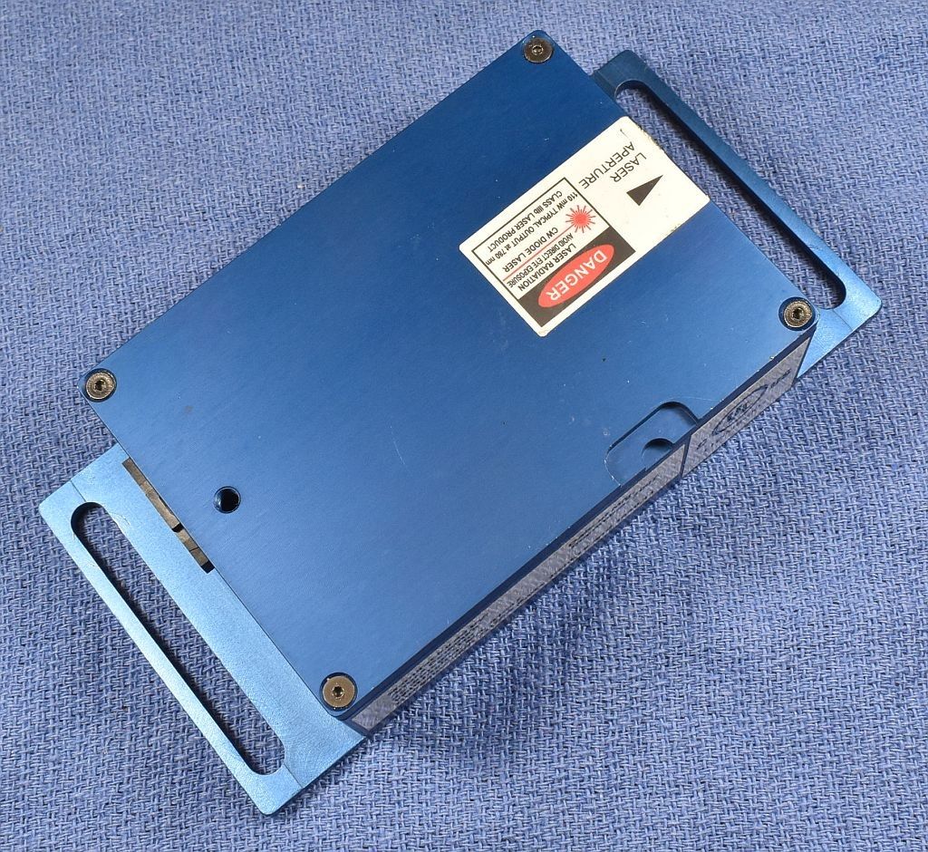
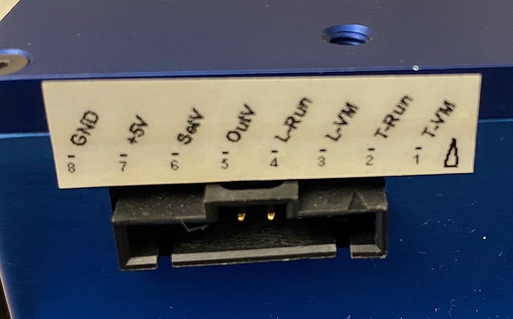
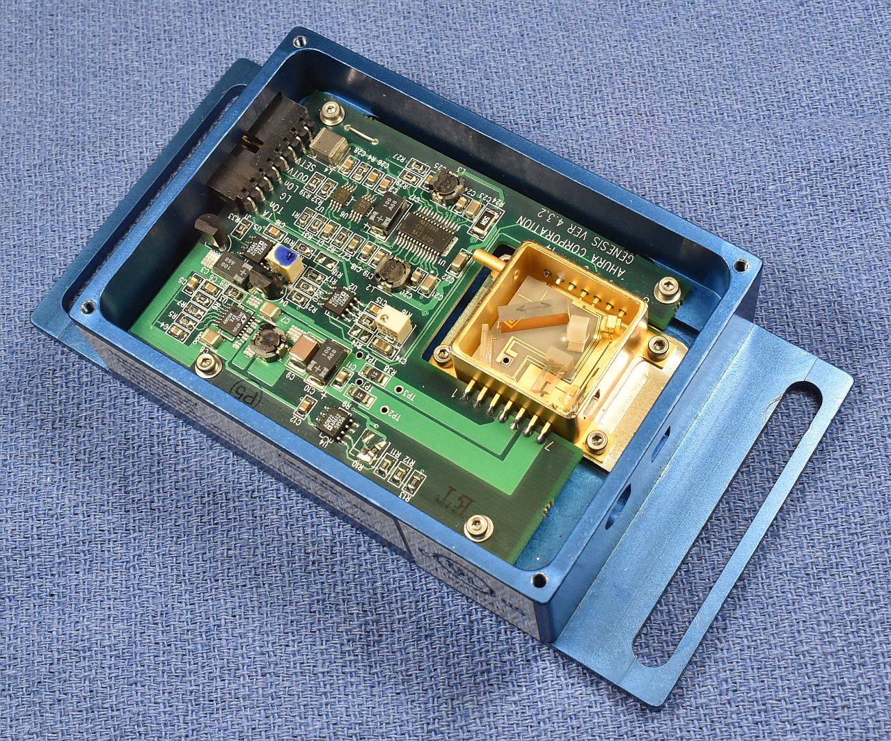
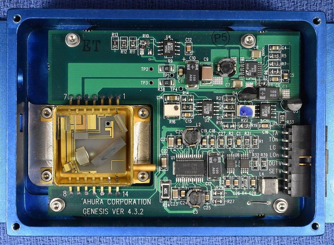
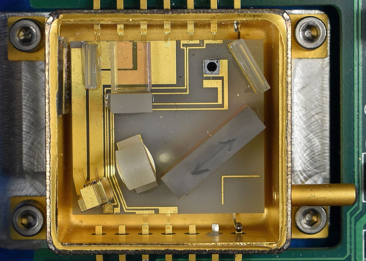
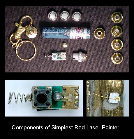
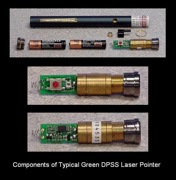
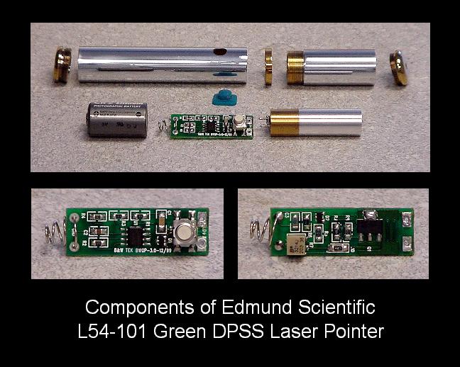
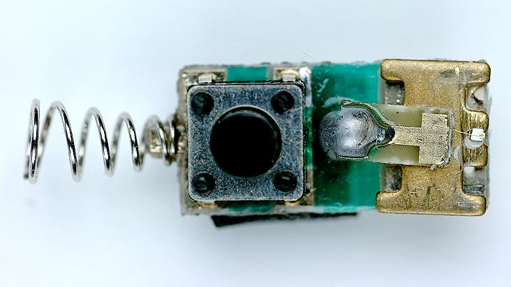
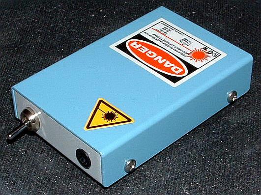
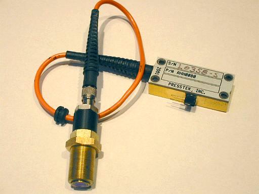
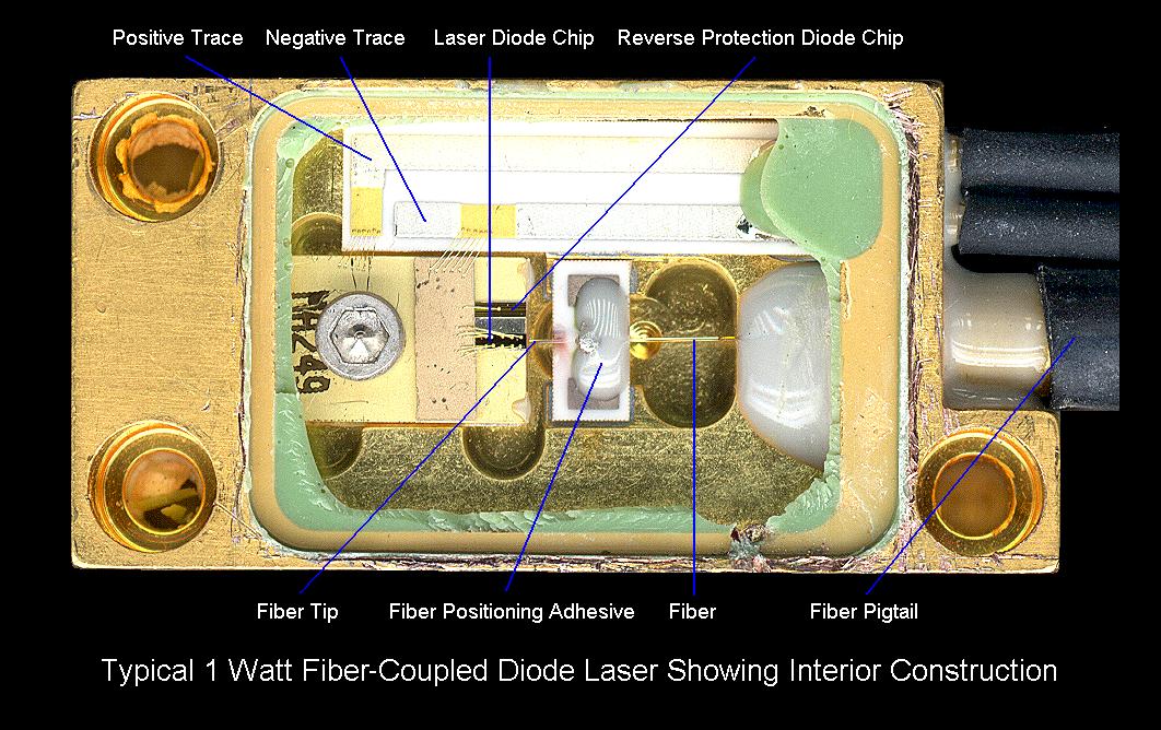
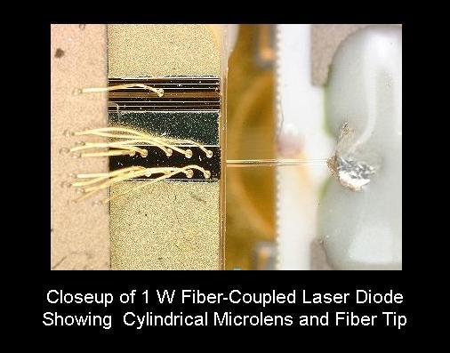
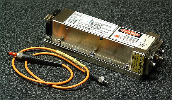
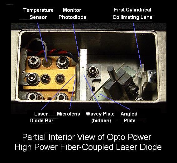
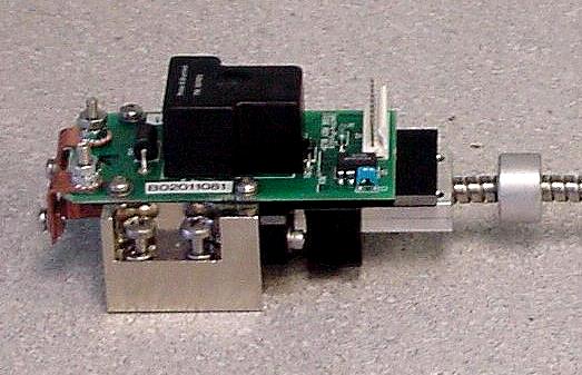
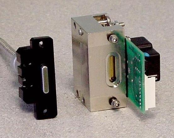
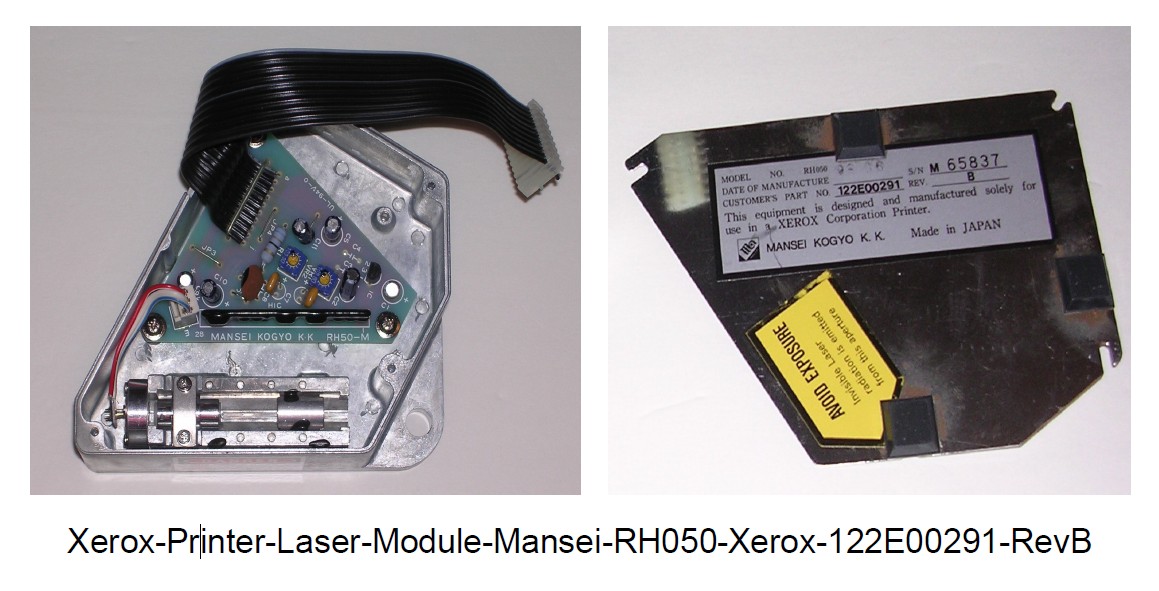
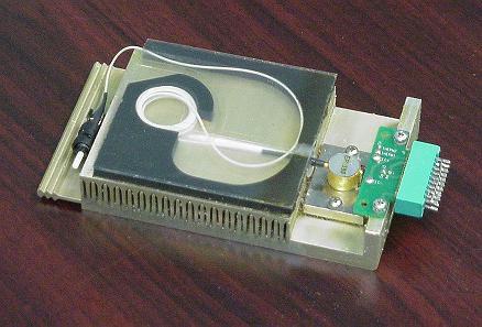
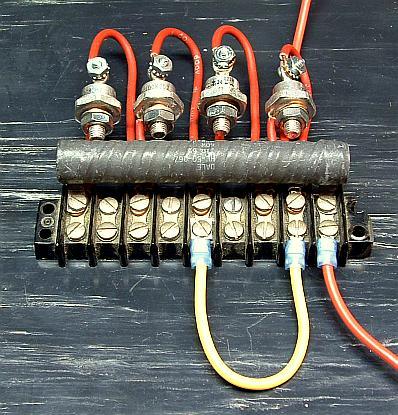
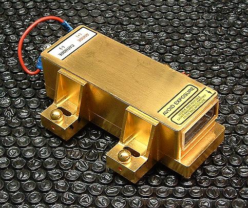
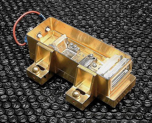
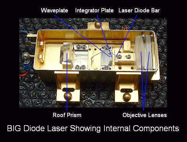
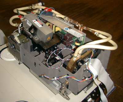
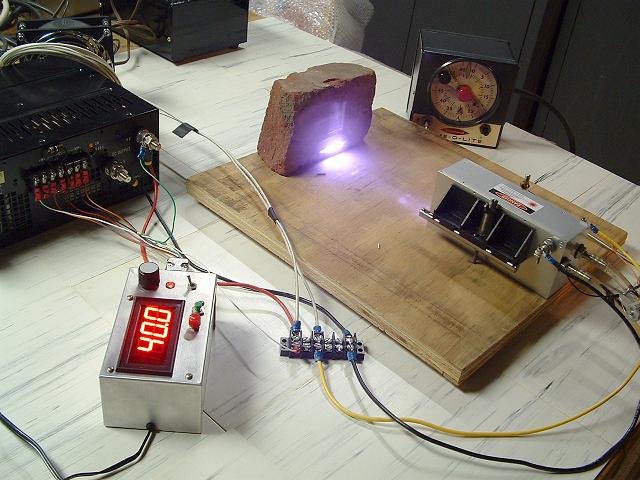
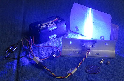
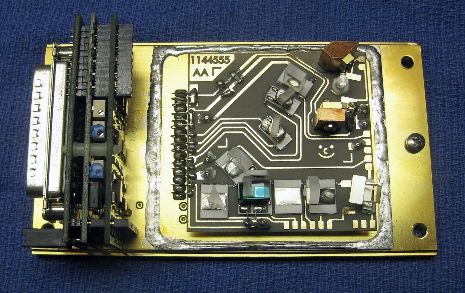
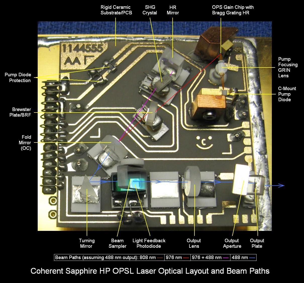
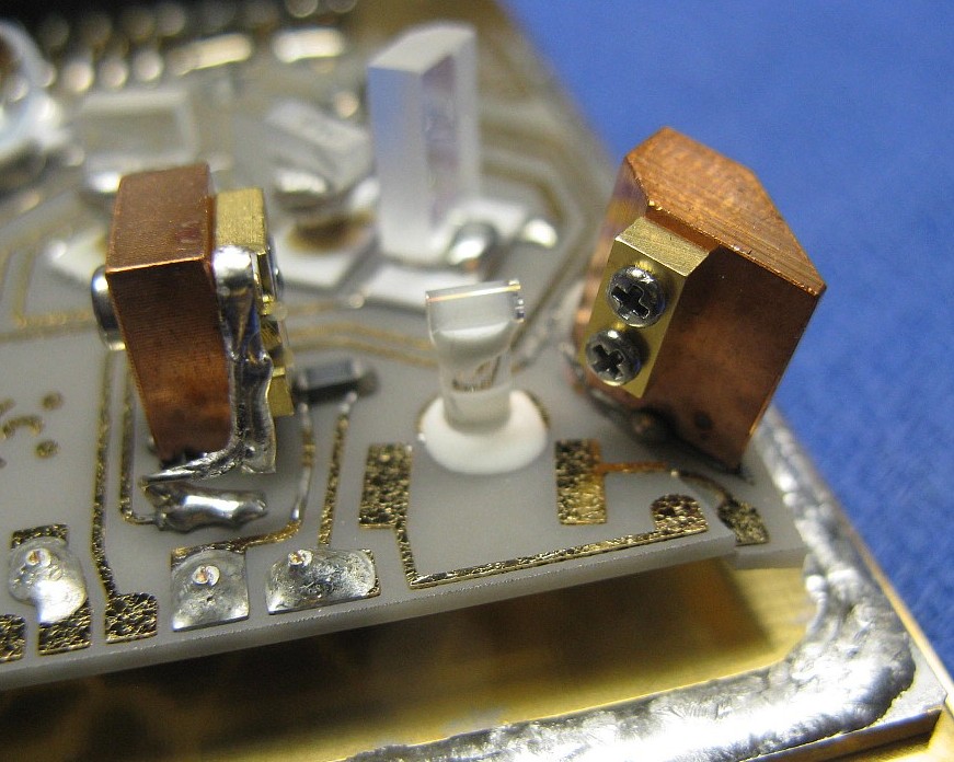
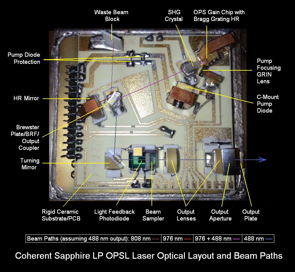
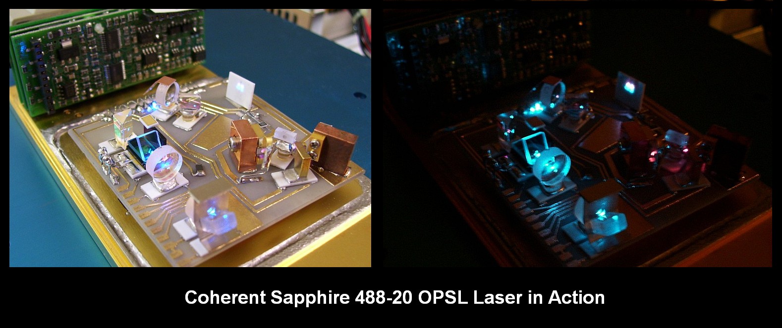
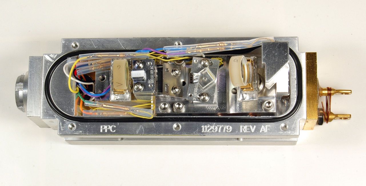
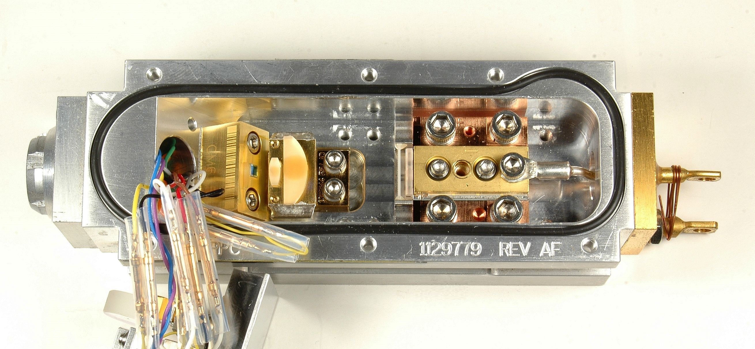
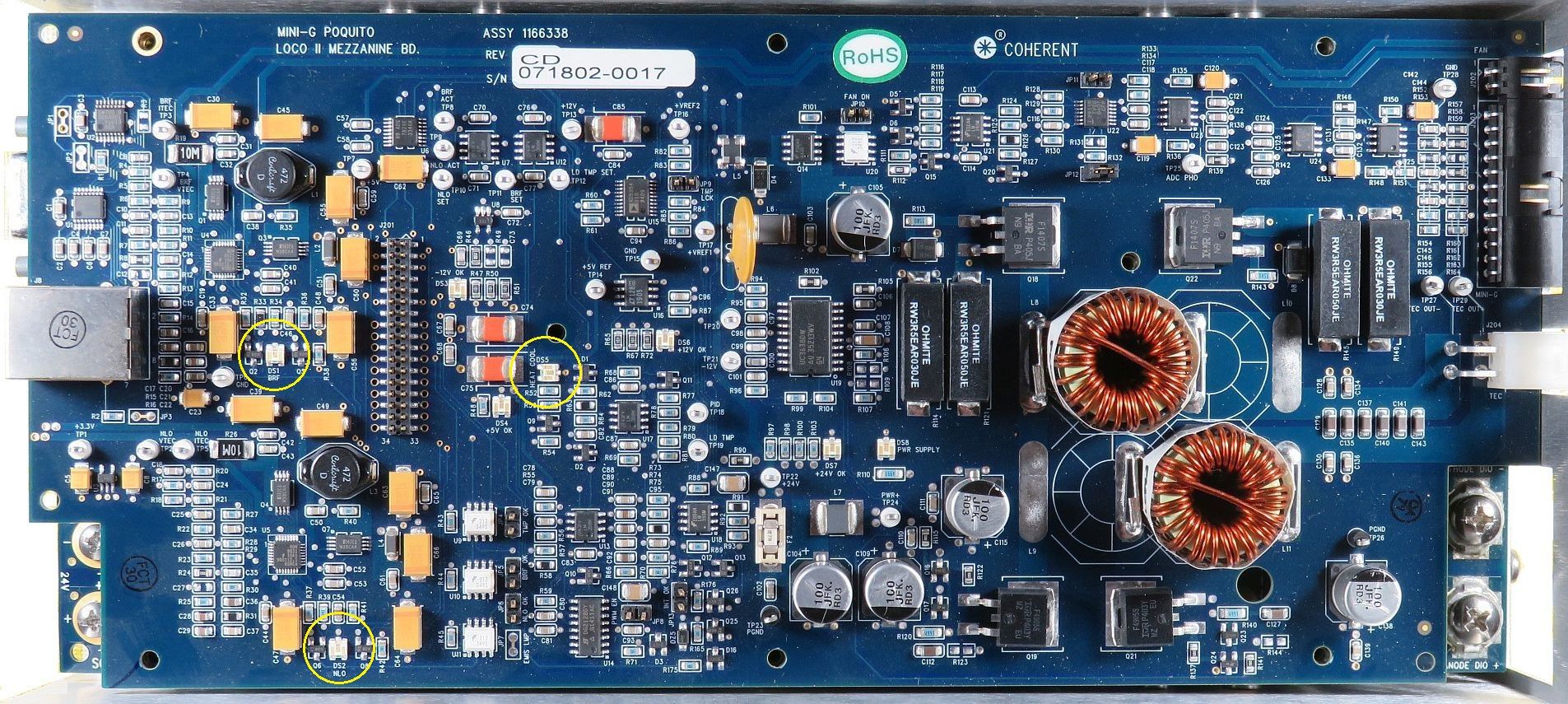
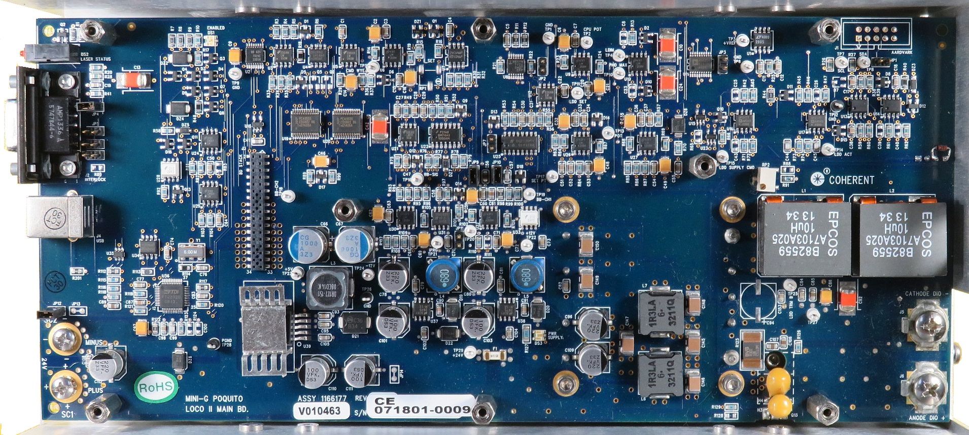
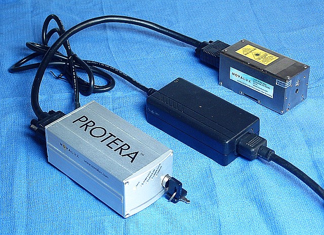
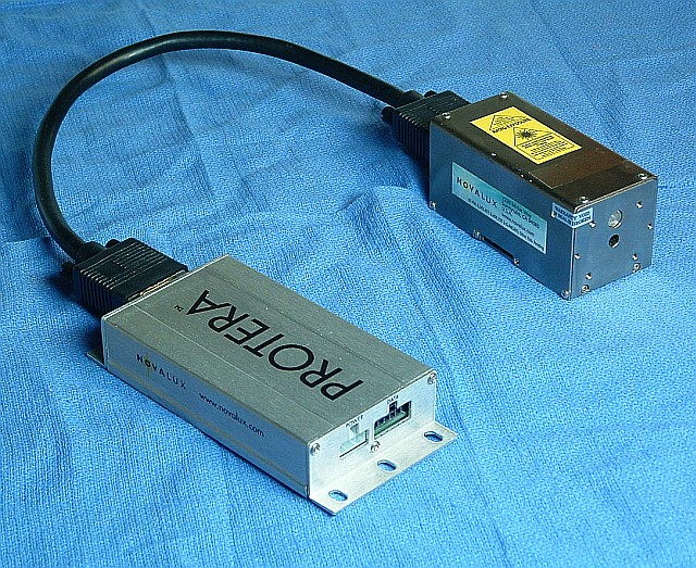
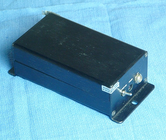
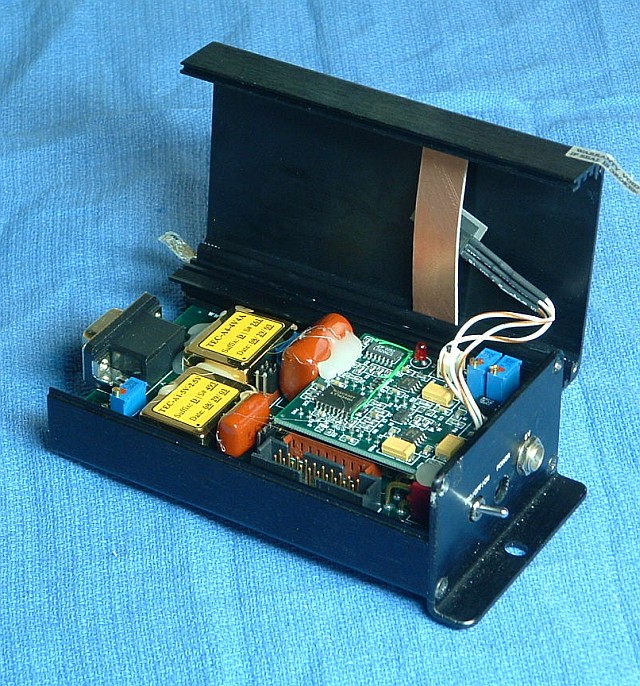
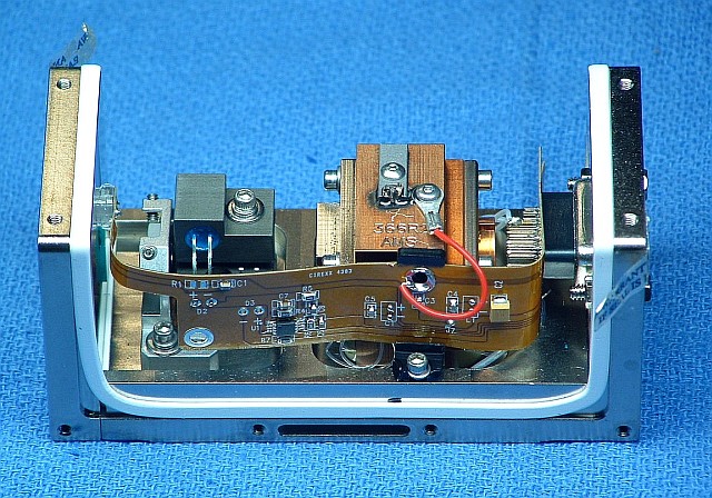
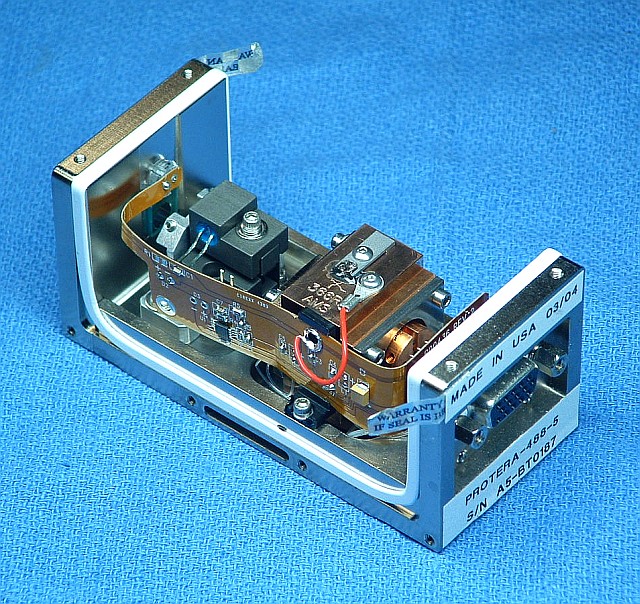
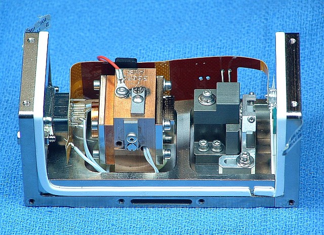
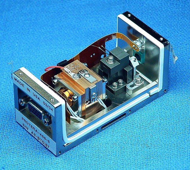
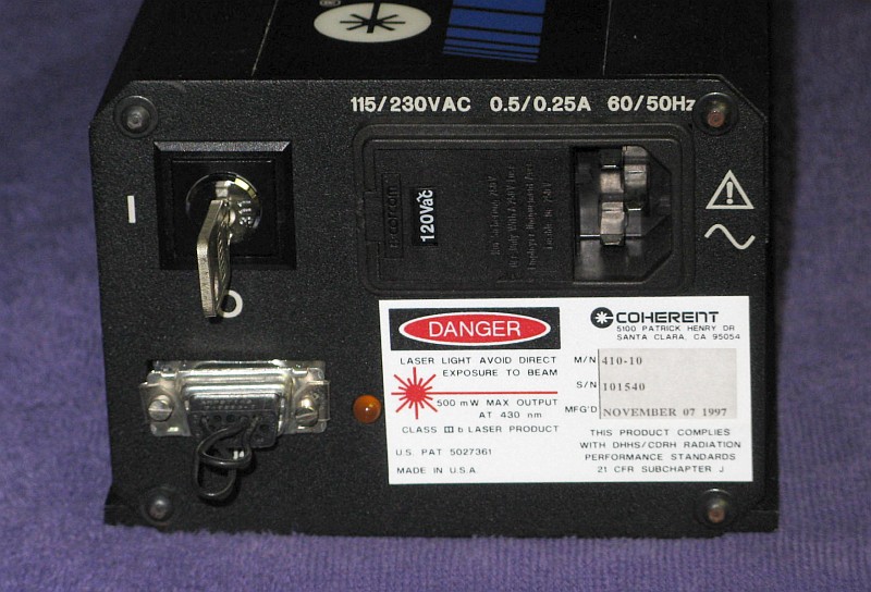
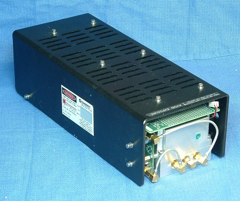
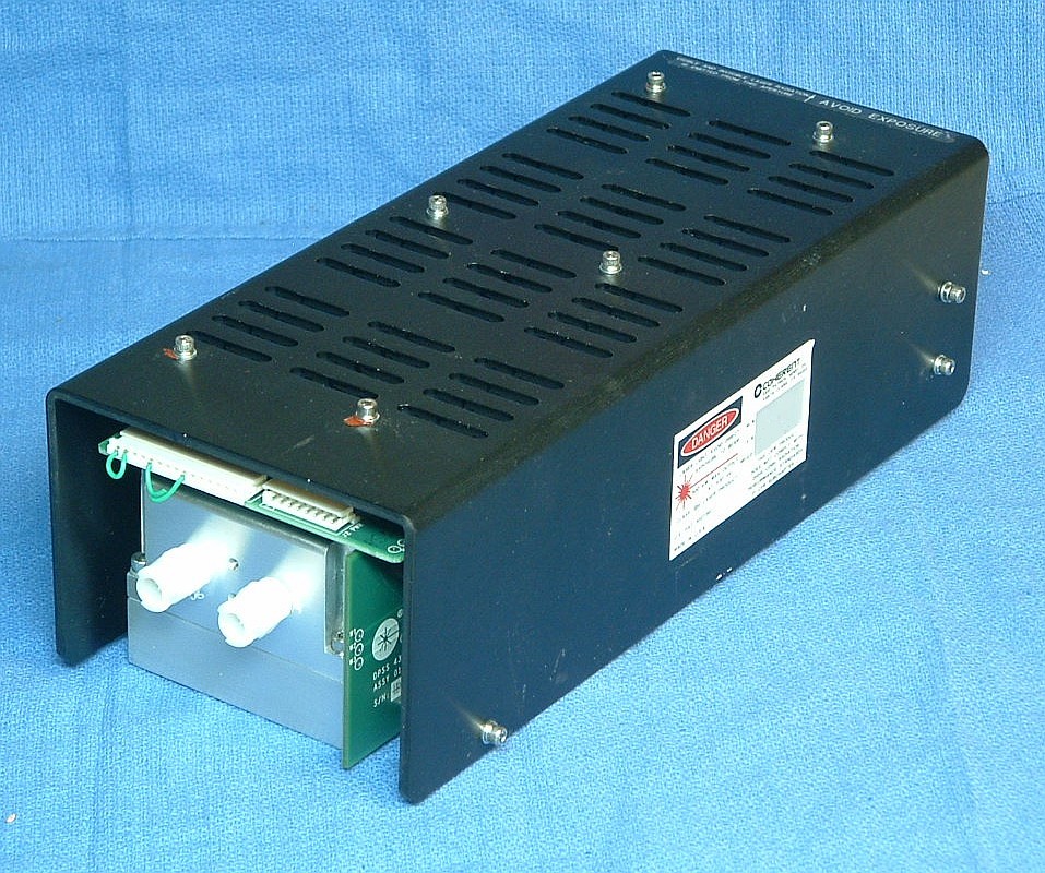
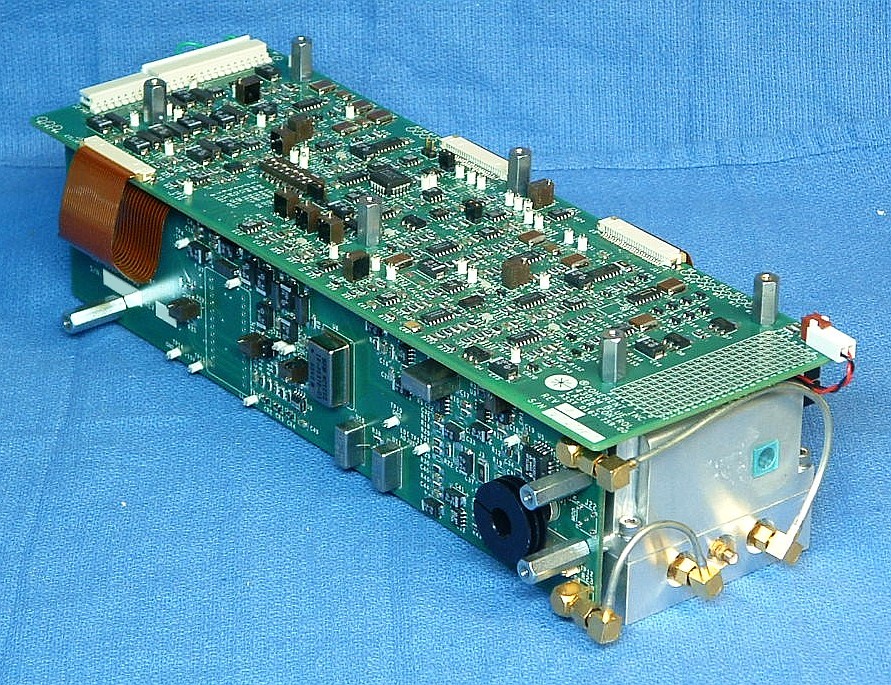
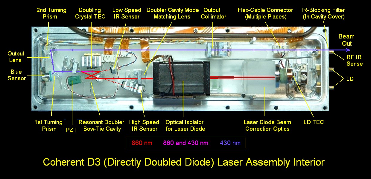
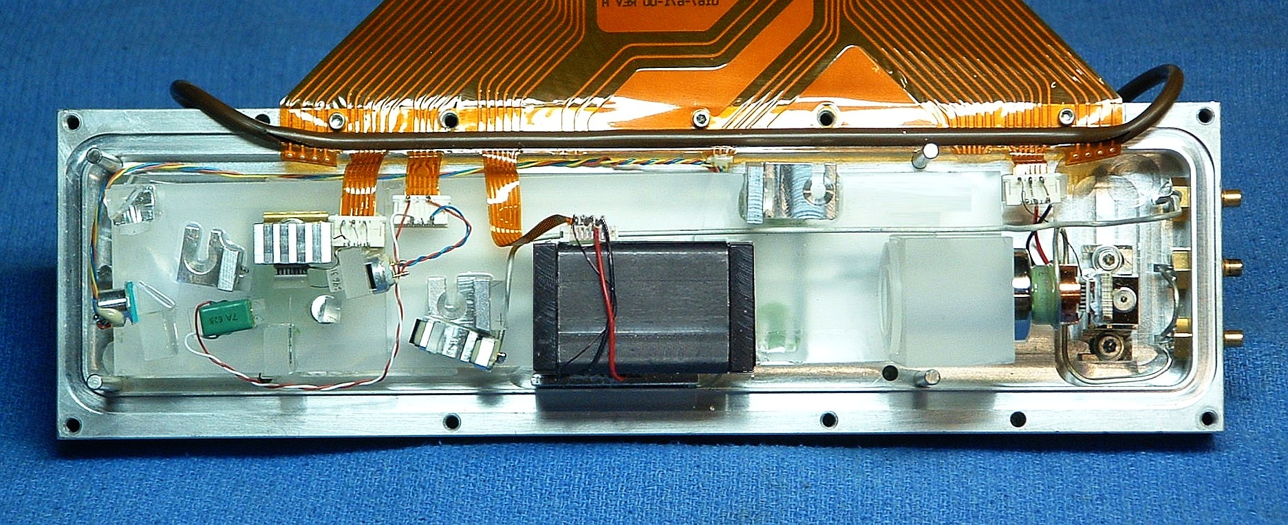
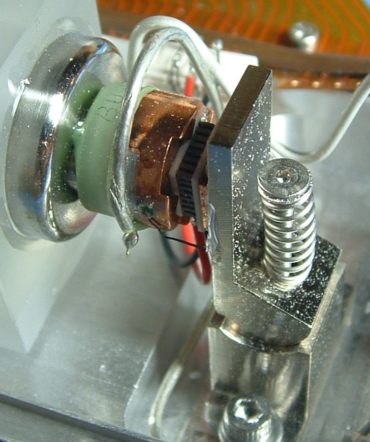
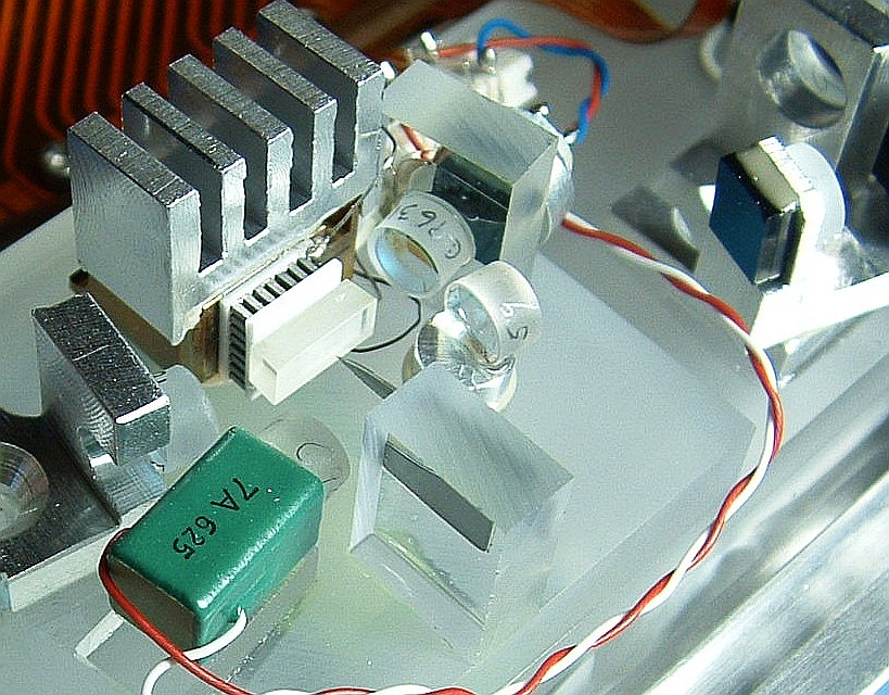
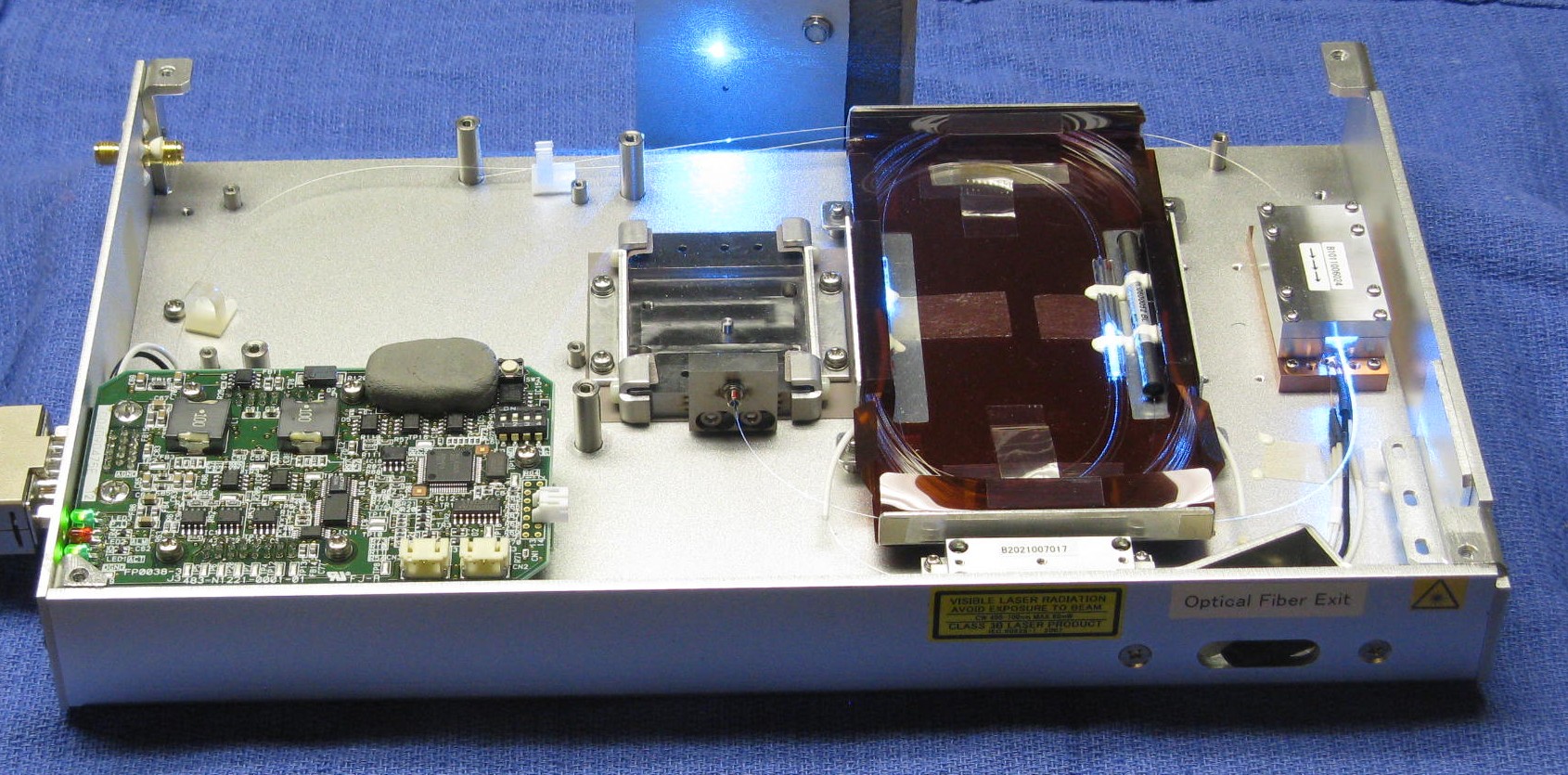
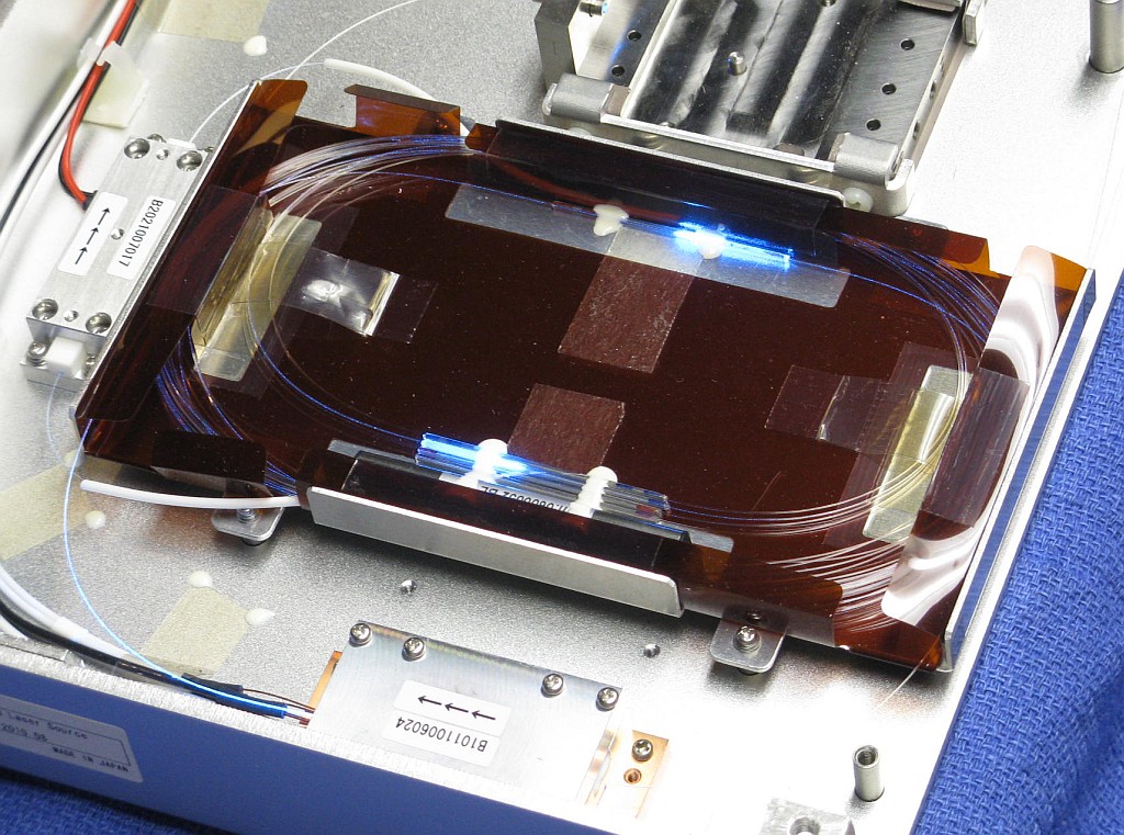
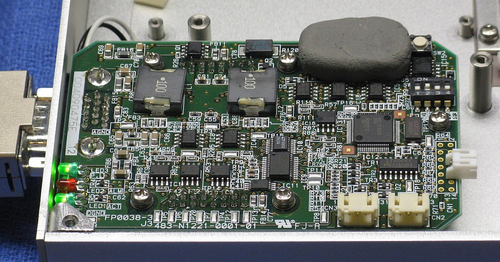
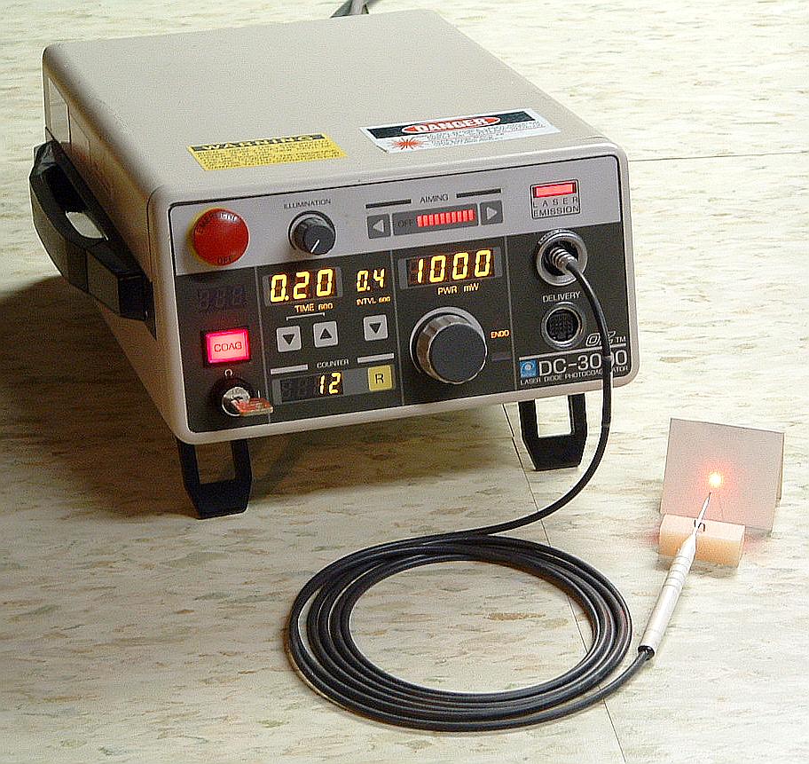
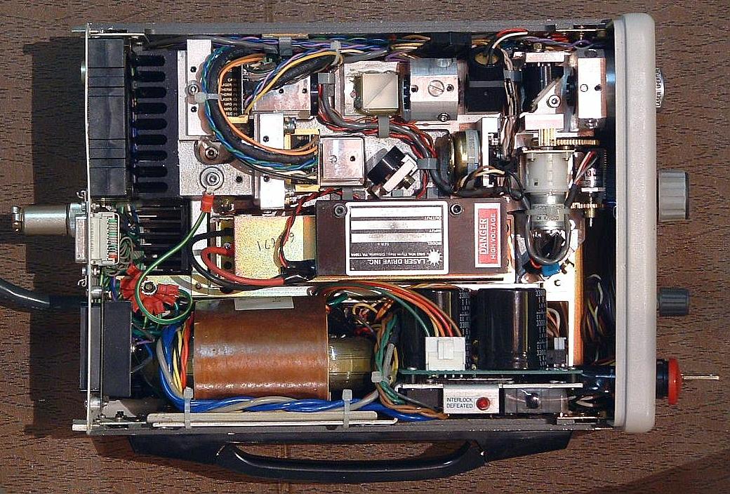
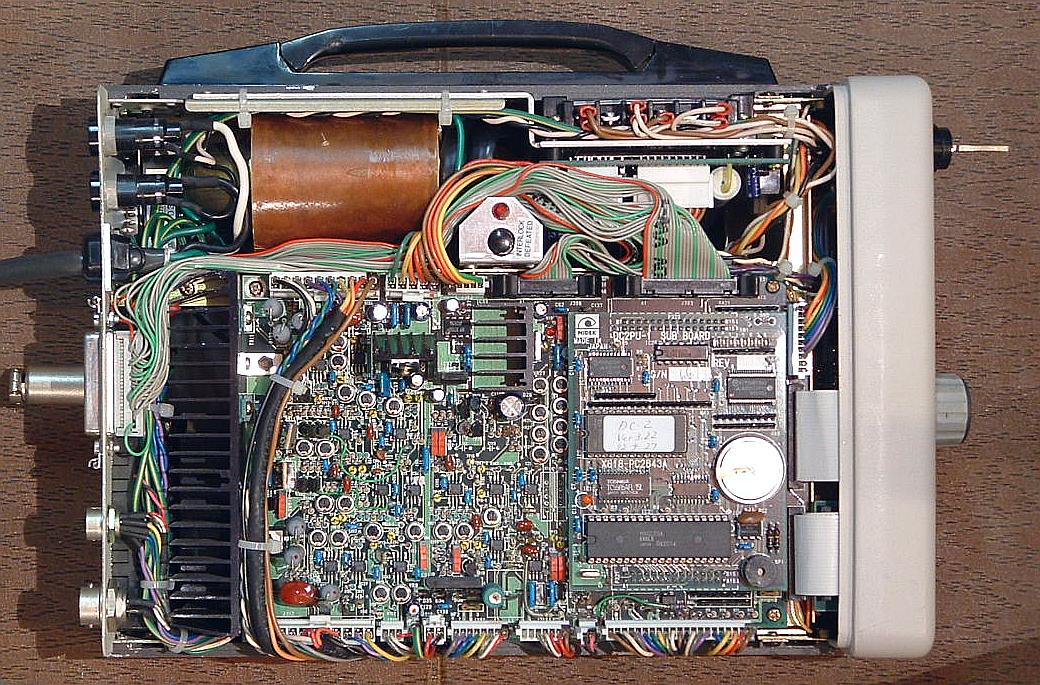