The optical output of a laser diode also declines as it heats up. This is reversible as long as no actual thermal damage has taken place. However, facet damage due to exceeding the optical output specifications is permanent. The result may be an expensive LED or (possibly greatly) reduced laser emission.
I accidentally blew one visible laser diode by neglecting to monitor the current but it wasn't the sudden effect some people describe - the current really had to be cranked up well beyond the point where the brightness of the laser beam stopped increasing. It did indeed turn into a poor excuse for an LED. One data point and you can conclude the world. :-)
Another one was blown by assuming that a particular driver circuit would work over a range of input voltages when in fact it was supposed to be powered from a regulated source. At first the degradation in brightness appeared to be reversible. However, what was probably happening was that damage to the laser diode was occurring as soon as the brightness appeared to level off. The natural tendency was then to back off and approach this same point again. Not quite as bright? Crank up the current. Finally, once it is much too late, the realization sets in that it will *never* be quite as bright as it was originally - ever again. This one still lases but at about 1/10th of its former brightness.
If you then try to power this damaged laser diode with a driver circuit using optical feedback, further instantaneous damage will occur as the driver attempts to maintain the normal optical output - which is now impossible to achieve and only succeeds in totally frying the device as it increases the current in a futile attempt to compensate.
And a comment about the expensive Nichia violet laser diodes (see the section: Availability of Green, Blue, and Violet Laser Diodes). Physically, they look like ordinary laser diodes and except for a higher voltage drop, the driving characteristics are basically similar. However, I've heard that they are even more sensitive to EVERYTHING than their visible and IR cousins and will degrade or die more easily. Since the wavelength of these diodes (in the 400 to 420 nm range) is basically useless for applications requiring visibility, aside from the "being the first kid on your block" factor, I'd stay away from them until the price comes down dramatically! I suspect that the newest 430 to 445 nm Nichia diodes are equally tempermental.
Also see the section: How Sensitive are Laser Diodes, Really?.
Believe me, it can get to be really frustrating very quickly blowing expensive laser diodes especially if you don't really know why they failed. This will be particularly true where the specifications of the laser diode and/or driver circuit are not entirely known - as is often the case. Helium-neon lasers are much more forgiving!
Buy one that accepts an unregulated input voltage. Otherwise, you can still have problems even if you run the device from a regulated power supply. All laser pointers and most (but not all) modules will be of this type. However, if you get a deal that is too good to be true, corners may have been cut. A proper drive circuit will be more than a resistor and a couple of capacitors!
To confirm that the driver is regulating, start with an input near the bottom of the claimed voltage range and increase it slowly. The brightness of your laser diode should be rock solid. If it continues to increase even within the supposedly acceptable range of input voltage, something is wrong with either the laser diode (it is incompatible with the driver or damaged) or driver (it actually requires a regulated input or is incorrectly set up for the laser diode you are using). Stop right here and rectify the situation before you blow (yet another) laser diode!
See the chapter: Laser and Parts Sources for a number of suppliers of both diode laser pointers and diode laser modules.
If you still aren't convinced that someone else should deal with laser diode drive design issues, the remainder of this chapter provides suggestions for integrated drive chips, sample circuits, and complete power supply schematics. But don't complain that you haven't been warned of the sensitive nature of laser diodes.
I'd expect to only see (3) and (4) in modern red laser pointers with (4) predominating in more modern designs. Expect (2) in green DPSS laser pointers (but many or most of these will also be pulsed).
(From gabbardo@cpovo.net.)
Well, I have in my hands a laser pointer that has only a resistor to limit the current instead of the transistorized circuits usually found. It have a 51 ohm SMD type resistor on the PCB in series with the power switch, the laser diode, and 3 LR44 batteries (1.5 V each).
In fact, the laser diode has no monitor photodiode at all - it have only 2 terminals. The metal case is open on the rear, so one can easily see the laser diode itself inside it. Interesting enough is that it is the only type of laser pointer that I can actually now find here (Brazil), but some years ago I bought some pointers having a complete regulator circuit.
(From: Sam.)
He's has sent me a sample, all the way from Brazil! Heck, it arrived faster than some of the stuff I send next door. :) As advertised, it certainly appears not to have anything inside other than a laser diode chip on a heat sink, 51 ohm surface mount resistor, on-off switch, and battery.
I have measured the I-V curve for both the overall circuit and just the laser diode. It is consistent with a 51 ohm series resistor and 20 ohm diode resistance with about a 2 V drop at just above 0 mA (the knee of the diode I-V curve). The threshold is around 15 mA and the operating current is 35 mA at 4.5 V (the normal battery voltage) - a rather wide range for a visible edge emitting diode. My hypothesis is that these laser diodes are specifically designed to have a wide operating range - possibly by reducing the reflectance of the output facet and thus the gain, possibly by varying the doping, or something else. So, efficiency is lower but with the benefit of increased tolerance to power supply current variation (though 35 mA for a few mW of output power is a very respectable value).
Someone else sent me a similar pointer and while I haven't actually measured its I-V curve, I expect that it behaves basically the same. These are both bullet-style pointers of obviously really cheap construction that came with 5 screw-in pattern heads (1 clear and 4 HOEs). Another better quality bullet-style pointer I have uses the normal laser diode in a can package with a regulated driver.
I also bought a couple dozen as-is pointers in a single lot on eBay which are all of this type.
"My laser pointer requires those little button cells which are really expensive and hard to find. I was wondering if I can instead connect 2 wires and make a battery pack for it using 3 AA batteries. Do all pointers have power regulators?"
They all have some sort of regulation but it may not be adequate to deal with much of a change. You would have to check circuit to be sure or use batteries that are exactly the same maximum voltage. Even that isn't totally guaranteed as really dreadful designs could depend on the internal resistance of the batteries to limit current. So, replacing AAA Alkalines with D Alkalines could cause problems with some designs.
To be reasonably safe, you would have to measure the current using a fresh set of the recommended button cells and then add enough series resistance to make sure the current can never exceed this value even with brand new AAs (or whatever you are using).
Note that the much more complex and expensive green laser pointers should have decent regulation but they may still assume that nicely behaved batteries are used. Therefore, if adding an external power source to one of these, it is best to make sure it is well filtered, regulated, and has absolutely no overshoot during power cycling. Also see the next section.
So, if you really want to run a pointer from an external source, the best thing to do would be to measure the voltage across a fresh set of batteries powering the pointer and build a highly filtered, well regulated power supply to match it. The power supply must have absolutely no overshoot or undershoot when power cycling.
Another not quite as robust alternative is to obtain a wall adapter with an adequate current rating and slightly higher voltage rating than the pointer's battery. Then, add series resistance until the voltage at the pointer is the same as when powered with its internal battery. This is risky, however, since unless the wall adapter is regulated (few are), ripple, line voltage fluctuations, and power surges will get through it - and any of these can fry a laser diode in next to zero time.
Also note that a fancy regulated power adapter may actually be deadly to a laser pointer. Power supplies that include active components (those using switchmode or linear regulators as opposed to simple wall adapters with only a transformer, rectifier, and filter capacitor) may produce sub-microsecond (or longer) overvoltage spikes when power cycled (at power-on or power-off). These will have no effect on most electronic equipment but may be fatal to laser diodes.
As far as connecting the power supply: If you don't mind drilling a hole in the case or end-cap, construct a dummy battery with contacts at each end which you wire to your external power supply. Drill a hole in the side of the case, or better yet in the cap (but off to one side so the cap will still make proper contact with the battery if you decide to use the pointer with a battery in the future) to allow the pair of wires to pass through after the cap is screwed on. There are all sorts of ways of doing this. The connections have to be made to the center spring contact on the circuit board at the bottom of the battery compartment and the case. Make sure you get the polarity correct!
Also see the section: Power Regulators in Laser Pointers.
Typical questions go something like:
In practice, whether this will work or not depends on the design of your laser pointer or diode laser module. Some have significant filtering and delays circuits inside which will make blinking at a useful rate impossible. Others will work fine. Still others will fail due to the repeated stress of on/off cycles.
Going any deeper into the circuitry than the batteries/power supply or on/off switch is definitely not for the beginner - if possible at all. Unfortunately, however, that may be necessary to achieve a useful result. For more info, see the sections of this chapter on laser diode power requirements, modulation, and the sample laser diode driver schematics.
(From: Peter Pan (peterpan@cheerful.com).)
Yes! I've used a simple 555 timer circuit driving an emitter follower transistor buffer amp, to drive several laser pointers. I've had little trouble recovering a near square wave at the receiving end with a phototransistor driven amplifier, up to about 5 kHz. After that, the residual energy stored in the laser module's driver circuit starts to degrade the square wave, but this can usually be extended, at least through the remainder of the audio range, by using a push-pull or complementary-symmetry type buffer, instead of a simple emitter follower. If you need to go beyond 4 kHz though, it is better to attempt to modulate the intensity rather then try to accomplish complete shut down/turn on.
Note: Free samples of ICs like laser diode drivers may be available for the asking even if you won't be buying a million parts in the future. Manufacturers often provide some means of requesting free samples at their web sites. Just be honest about your needs - they consider it good PR and you might just tell a friend or colleague who WILL buy a million parts!
(From: Steve White (stevew@hitl.washington.edu).)
We are using the OPA 2662 (Burr-Brown) for this. It is an OTA with 370MHz BW, 59 mA/ns SR, and can source/sink 75mA of current per channel (two channels per chip which may be paralleled quite easily). The part provides the emitter of the current source to an external pin (programming side of an internal current mirror), so that a single resistor sets the voltage-current transfer characteristic. Watch out for the dependence of the harmonic distortion specs upon the supplied current and frequency though...if this will be a problem for your particular application that is (didn't matter much for mine).
Another chip, the EL6270C, features an integrated high frequency modulator (HFM) oscillator to provide output current drive of up to 100 mA, an external resistor that controls the average laser diode output power, and a low power disable mode that powers down to 5 uA.
Complete datasheets are available at the Elantec Web site.
Check out the datasheets for several laser driver circuits available on the market for high speed fiber communications. See Maxim, HP, Sony, Philips, Fujitsu, Microcosm, etc. Also, there are many papers in Bell System Technical Journals that deal with other bias control schemes that don't involve optical feedback.
App Note AN52 (and probably others) includes a sample circuit using their one of their chips (not necessary dedicated laser drivers) for powering laser diodes. In AN52, the LT1110 Micropower DC-DC converter is used as the current regulator for operating from a 1.5 V battery. However, it is possible that behavior at low battery voltages might be undefined - and bad for the laser diode! I wonder if they tested for that? :(
There is an article in the November CQ magazine by WA2NDM entitled, "A Laser Diode Transmitter" which is based on AN52. However, his circuit uses an audio transformer to directly modulate the laser diode current and it would seem that without some additional protection, if someone were to accidentally drop or tap on the microphone - or power cycle the preamp - poof goes the laser diode! :(
Laser Diode Power Supply 3 (RE-LD3) uses a similar chip - the LT1054 DC-DC Converter, not for voltage stepup but to very effectively isolate the laser diode from input voltage spikes.
The MAX3261 (1.2 Gbps), MAX3667 and MAX3766 (622 Mbps), and MAX3263 (155 Mbps) are examples of their highly integrated laser driver chips.
The Maxim Engineering Journal (a monthly or so publication you will receive if you have requested their CDROM and possibly included in trade rags like EDN and Electronic Design) sometimes has laser diode related articles. For example, the Special Fiber Optic Edition (early 1999) is devoted to applications of Maxim's high speed (622 Mbps and up!) optical interface components including laser diode drivers and sensors. (The Maxim application note Driving a Laser diode at 622 Mbps From a Single +3.3V Power Supply may be one of those from this publication.) The next issue I received, Volume 33, included a circuit similar to the one described in Digitally Controlled Laser Diode Driver.
(From: Art Allen, KY1K (aballen@colby.edu).)
I called a person I know who works for a major surplus house. He asked NOT to be identified. He did give me valuable information regarding the NS102 laser driver modules that are being sold for $3 each (in large quantities) on the internet.
Here's what I was told.
The NS102 is mass produced in Asia. The chip that the NS102 PCB is based on is unknown, and probably made in Taiwan too. There are no specs for it. Only DC parameters are given on the 'rough spec' sheet (advertising quality literature) the sellers give you.
They do work and they work well.
They use low power and they are stable-if the voltage in changes from 4v to 8v, the LD output remains fairly constant.
(From: Sam.)
The following is apparently not quite correct. According to someone who works with NVG, they can be modulated at up to 2 MHz. See the section: Comments on Some Commercial Drivers and Detectors
(From: Art.)
However, they are NOT suitable for modulation of laser diodes and should only be used as a laser pen power supply!
I have an email from a vendor here which sparked all this speculation regarding their suitability for our purposes. The email CLAIMS they can be driven to 12 Mhz output pulses while maintaining FULL APC (not average output monitoring as they do in fiber optic drivers). As far as I can tell, this is just plain a lie and no one should purchase these expecting to modulate a laser diode for communications purposes.
They are probably little more than the standard 2 transistor laser driver that can be used for a laser pointer because it is heavily bypassed with a heavy duty slow start ramp up circuit.
Some vendors are now selling these for $20 in small quantities - don't get taken in - it's a laser pointer driver and NOTHING MORE.
If anyone has better info or has tested one of these on the bench, please let me know. I'd really like to get info on the chip contained on the PCB too.
The following refers to chips available from NVG, Inc. and other resellers of their products. See the section: Mail Order - Lasers, Laser Parts, Optics, Accessories for more info on NVG.
The NVG laser driver circuit was originally designed for CW only. While I did not design the driver circuit, I was able to find a way to get it to modulate successfully up to 2 MHz. I have successfully built a free-space FM modulated data/voice transmission system using the NVG laser modules (diode, driver, collimator, enclosure) already set and burned in).
In addition I have helped a number of customers from around the world (Spain, Italy, Switzerland and the US) use the NVG modules in a modulated design.
While the NS102 type driver circuit does have a 0.1 uF capacitor to act as a 'soft on'/filter protection of the laser diode, by providing enough voltage to keep the module/laser just below the threshold, you can modulate the NVG modules (or any suitable diode attached to the NS102 driver) up to 2 MHz. At that point, it seems that the capacitor effectively filters the modulation and the circuit 'saturates' and only produces CW output.
Another strategy is to 'inverse' modulate the module - that is, keep the module effectively on with the modulation signal causing a decrease in power - rather than have the laser off with modulation causing an increase in signal....
See A Simple PLL Based FM Diode Laser Module Modulator for an example of one approach that works with the NS102.<
(From John Sojak (trax@allways.net).)
As far as modulation is concerned, the Analog Devices driver is hard to beat for three bucks. Couple that with a 555 and a battle proven LM317 front end and cry 'BINGO'. Maxim used PECL inputs ... arrgh! I don't need to spit photon packets at 150 mhz! Linear Tech IR receiver looks good, although the $7.00 price tag + a handful of linear doesn't really appeal to me. Too bad you can't get inside the Epoxy covered die in the Sharp TV/VCR consumer IR receiver modules (apx $1.50/100 pcs). Not everyone in the world wants to decode bursts of 40 kHz back into data!
Oh, by the way - an Optek BP812 Optologic sensor performs quite well at at 760 nm. It's an active device available in either totem pole or open collector outputs. The applications guy at Optek says the device won't work at 760 but looking at the response curve, I disagree. It's response is only down about 10% in the reds! Most silicon photo stuff is down about 60-75% at 760ish nm. From what I have seen, the device is very usable at 760 nm. Useful part for red diodes and HeNe stuff.
This is getting a little scary. Laser diodes have been around for a good few years now, and I thought it was fairly widely known how you make them go and (harder) keep going for a long time; but there have been several postings recently from folk who are busy making themselves poorer by driving lasers inappropriately. Here are the rules on how you do it right:
         ^ Light Output
         |
         |
         |- - - - - - - - - - - - - - -* ---- Maximum Rated Light Output
         |                            *|
         |                           *
         |                          *  |
         |                         *
         |                        *    |
         |                       *
         |                      *      |
        -|*--*--*--*--*--*--*--*-------+--------------> Forward Current
         |                     |       |
                               |       |<-- Maximum Current
                               |
                               |<-- Threshold Current
The snag is, the difference between threshold and maximum current is usually
quite small; no more than 10% or 20% of the threshold. The threshold current
varies greatly from one device to another (even within the same type number)
and also varies with temperature. Result: setting a fixed current value is
doomed to failure. For some lasers, and on some days, it will be under the
threshold and no laser action will occur; on other days, it will be over the
maximum current and your precious laser will turn into a useless LED (like the
original posting in this thread). The only safe way is to use the monitor
diode current to servo the light output. Even this isn't ideal because the
monitor current is different for different lasers, but:
Sharp (one of the big suppliers of laser diodes) also make some nifty 8-pin drive chips that are pretty good if you don't need to modulate the laser rapidly. For modulation, consider setting the light output close to 50% of full output using a really slooooowww-responding feedback circuit, and then impressing a fixed-amplitude modulating current on the laser. This is OK because the gradient of the light/current graph is reasonably predictable for any given laser type, so it's possible to calculate a suitable safe modulating current from the data sheet.
Good luck to all - and don't forget the eye safety regulations.
(From: Paul Mathews (optoeng@whidbey.com).)
Laser diode structures are usually so small that damage thresholds are very low on every dimension. The general approach to protecting them is to series AND shunt filter (and/or clamp) supply voltages to limit the voltage compliance of current source driving circuits. Also, consider having some of the current limiting be by means of an actual resistor rather than just active circuitry. The parasitic capacitances in active driving circuitry can interact with dv/dt on supply lines to turn on the drive circuit (e.g., drain to gate capacitance with MOSFET drive), so the resistor limits current even when this happens. Using bypass capacitance local to the pulse current loop has the dual benefit of absorbing residual transients and avoiding any effects of upstream series filter components on speed.
(From: Mark W. Lund (lundm@physc2.edu).
You can blow out the laser in nanoseconds if there is enough voltage and/or power in the pulse. Two methods: electrostatic discharge type damage which punches holes in the cavity; brief high power which damages the front facet.
Make sure that the power supply to the modulation circuit is filtered to prevent surges, isolate the signal circuit to prevent surges on the input line from getting to the laser.
There are an infinite number of ways to get a damaging pulse. Most common is the power supply. It helps to have a scope capable of capturing transients for this. The other ones that I will admit to: using a circuit that wasn't grounded to the metal optical table--brushing the table with one line of the circuit and oops; a commercial laser diode power supply that was clean until we used it in computer control mode when it sent out very fast (anhard to see) spikes; hooking the laser up backwards; using a power supply that had a big capacitor across the output which had enough charge in it to do damage; and forgetting to put a peltier cooled laser on a heat sink (the more current I gave the cooler the hotter the laser got....oops.)
Well, that was embarrassing, but I hope it encourages others to save a few (laser diode) lives.
(From: K. Meehan (meehan@srvr.third-wave.com).)
Semiconductor lasers are very sensitive to power spikes. The level of current that is a problem depends on the laser structure and how much of the current is converted into optical power vs. heat. In general, reverse current spikes are very damaging, no matter what level. Make sure that you are modulating the diode so that you go below laser threshold but not below 0V. In the forward direction, very short overshoots (<1microseconds) in current can be handled until you blow the facet off of the device (catastrophic optical damage - COD). Longer pulse overshoots aren't any better. The current level that damage occurs varies from device to device. I tend to recommend less than 10% overshoot in all cases. COD is very easy to note, just look at the laser (while it is not operating) under a microscope. The facet coating is damaged near the emission region, if there is a coating. Otherwise, you will see an enhanced region (darker area) when looking under Nomarski - maybe not so easy to see.
Another problem that you might be having is spiking during start-up or shut-down of the device. Current supplies that look lovely during operation sometimes have spikes in the output when you turn them on or off. You might want to short the device, making sure that there is no bounce during the shorting, before turning your supply on or off. There are several laser diode driver companies out there that make current generators with slow starts and minimal overshoots. Avtech, Melles Griot, ILX Lightwave, WAvelength Electronics, etc.
"I am designing a driver circuit for a laser diode (NEC NDL3220S). The problem is that the spec sheet says the output of the monitor photodiode at rated power is max: 0.5 ma, typical: 0.3 ma, min 0.1 ma, at 5 V. This is a huge range! If I set for 0.3 ma and the actual output is 0.1 mA I will burn out the laser. I do not have equipment for calibrating the laser output directly."(From: Alan Wolke (74150.451@CompuServe.COM).)
Welcome to the wonderful world of laser diodes! You'll find that a 5:1 range in monitor current is typical, with even a full order of magnitude being common! This is one reason why most laser diode based applications have a provision for trimming/tuning the driver circuit to the particular laser.
Your safest bet is to design the feedback loop to operate with less than the minimum monitor current, and provide the ability to actively tune it to the appropriate operating point. Thankfully, the relationship between output power and monitor current will remain reasonably constant over the lifetime of each particular device. So, once it is properly set, you're done.
For those of us who have performed the infamous LD to LED (LD->DELD) conversion more often than we'd like, there's an interesting item mentioned near the end of the article: Visible-Laser Driver Has Digitally Controlled Power And Modulation regarding LD drivers. It points out two important characteristics of LDs:
(From: John, K3PGP (k3pgp@qsl.net).)
For high speed data and very high frequency RF subcarrier/video work I've always biased my laser diodes to 1/2 laser power then modulated them near 100%, much the same as a standard AM radio transmitter. This does result in a faster response time rather than cutting the LD completely off. It's also probably a bit easier on the laser diode especially if it's a high power unit. (Mine draws 1 amp when putting out 500 mw.)
I never tried biasing it down to BELOW laser threshold at the 'LED' level. Although this would be an improvement over cutting it off completely, I would think this would be slower than biasing to 1/2 laser power.
(From: Sam.)
Also see the section: Digitally Controlled Laser Diode Driver which has a bit more on the circuit mentioned above.
CAUTION: If you remove the optics from a diode laser module, the power may increase resulting in laser diode destruction, especially if the unit is being run near its maximum ratings.
(From: Frank DeFreitas (director@holoworld.com).)
The information sheet for a Power Techologies 35 mW module states in bold capital letters not to even ADJUST the collimation while the diode is running at full power!
I've got a little 10 mW, 635 nm diode that I tested with and without optics. Here are the initial readings:
It is interesting to note that the second reading WITHOUT optics was 3.8 mW and the third reading 2.6 mW. The barrel was becoming very hot. I killed the power before I killed the diode (I'm learning!). So this particular diode (from NVG, Inc.) obviously was set up with the collimating optics in place NEEDS the feedback (reflection) for the photodiode to control the current.
You can't modify a sealed diode laser module in this manner unless it already has a modulation input but if you are building something from components, it should be possible. Loop stability must take into account optical path delays if the distance between the laser diode and photodiode is significant but this shouldn't be a problem unless you are also trying to modulate the thing at a very high rate. Obviously, any such scheme must assure that the external photodiode always intercepts enough of the beam and/or that a hard limit is imposed by feedback from the *internal* monitor photodiode to assure that the laser diode specifications are not exceeded under any conditions. Otherwise, even an errant dust particle or house fly wondering into the portion of the beam path used for feedback could ruin your laser diode!
The dire warnings about instant destruction from overcurrent still apply but but the extreme non-linearity typical of low power laser diodes isn't usually present with higher power devices. There is still a lasing threshold but above this, the output power increases linearly with current and there is likely to be decent consistency from unit to unit. However, proper current control and temperature compensation (or adequate derating) is still essential.
(From: Art Allen, KY1K (aballen@colby.edu).)
When you get into the 1 amp diodes (or anything over 200 or 300 mw), the driver becomes less dependent on the laser power feedback PD and many of these higher powered diodes just don't have the power sensing PD on-board for this reason.
While the threshold current is still very dependent on the temperature of the diode, the DIFFERENCE between the max current and the smoke release current widens a lot - meaning that the larger diodes can be operated fairly safely without sampling the output and applying variable current based on the power sensing PD.
The 1 watt diodes that I was trying to buy several years ago had 2 sets of specs-one at ambient room temperature and the other set for diodes at actual operating temperatures-the inference being that the preferred driver needed TEMPERATURE feedback in order to ramp the diode up to operating temperature.
Note that these diodes were used to drive fiber optic cables where they operate as an FM transmitter (constant carrier/fixed duty cycle transmit), so they probably used a time delay circuit to ramp them up to temperature rather than an actual temperature sensor.
Where the diode (probably) isn't on constantly, it might be necessary to derate the diodes and operate them just above threshold in order to be safe.
For your high power diodes, you can use a simple constant current driver (assuming the diode doesn't require PD based power sensing feedback.
The Vishay Siliconix catalog has an ABSOLUTELY O-U-T-S-T-A-N-D-I-N-G technical description of MOSFET based constant current source design. You can request the hard copy of the catalog from their website, make sure you get the full catalog with the ap notes. (I couldn't find this on the Vishay Web site but it may be: "AN103 - The FET Constant-Current Source/Limiter". Feeding "Vishay AN103" to a search engine should return the PDF.)
(From: John, K3PGP (k3pgp@qsl.net).)
I'm presently using the power supply under Biasing & Modulating Laser Diodes - Safely ! on my Web site with a Russian-made 1 watt 810 nm laser diode. The diode looks like one of those old time big metal (TO-3 ?) transistors but with a hole in the top of it. The series resistor in this case was made up out of a bunch of parallel connected 1 watt 33 ohm resistors. I think I ended up with around 10 to 12 in parallel. This allows me to adjust the laser current in small increments by adding or subtracting from the number of 33 ohm resistors. It also solved the problem of trying to find the exact value I needed in a high wattage resistor. (Wattage rating goes up as you parallel resistors, resistance goes down.)
I ended up feeding half of the 33 ohm resistors from one 7805 voltage regulator and the other half from a second 7805. Even though one 7805 can handle one amp of current it began to show signs of thermal drift when running at this level. By splitting the resistor bank in half each regulator only needs to supply 1/2 amp.
A 808 nm 500 mW laser diodes are visible but barely. Do NOT be fooled into thinking it's not really putting out much power. Human eyes aren't that sensitive to 800 nm radiation BUT you can easily burn a hole clean through your retina with this much power. If you doubt this, try focusing your 808 nm 500 mw laser on the black plastic part of a VHS video cassette and see what it does. When I do this with mine I get instant smoke and liquid plastic. So, BE CAREFUL especially when focusing this diode down to a small spot.
When playing around with stuff like this you will notice that color has a LOT to do with how much energy is absorbed. Aiming the same laser at the while label on the same cassette resulted in nothing happening. There is a very important principal to be learned by this experiment. If the white label isn't absorbing much power from the laser beam then it has to be going some place else. The answer of course is it's being reflected (scattered) back from the white surface. Keep this in mind when playing around with this diode. If you hit something that's even remotely reflective you could end up with the beam coming right back at you and you might not even be aware of it since the human eye is not very sensitive to radiation in the 800 nm region.
For communications use you might want to consider expanding the beam. This will lower the power density and make it a LOT safer if you accidentally get in the beam. The beam exiting mine is approx. 4 inches in diameter. 500 mw spread across a 4 inch diameter circle is a LOT less dangerous than 500 mw focused down to 1 mm in diameter!!!
And remember that a 500 mW 808 nm laser diode needs a GOOD heatsink. If you notice the power dropping off shortly after you turn the laser on your heatsink is too small! If you are having problems with this and you don't have room for a bigger heatsink use a small 12 VDC fan. Try to direct the air across the heatsink and NOT across the optics!
You can monitor power output with a regular silicon solar cell hooked directly to a milliamp meter (not a voltmeter!!!). Do NOT use any series resistor between the solar cell and meter. Expect to see over 100 ma of current at this power level. I also suggest you expand the beam to make use of most of the surface of the solar cell. If you focus it down to a small diameter the power density goes up and you just might burn a hole in the solar cell! Plus a very narrow diameter beam could easily bounce off the shiny surface of the solar cell and hit you in the eyes with enough power density to do some real damage! Watch the angle between the solar cell and the laser and anticipate where the reflection might fall. You will get the same power reading no matter what the beam diameter is as long as all the energy hits the solar cell. You can substitute a white piece of paper to get some idea of beam diameter but be CAREFUL when doing this!
Treat this laser with respect. Anticipate reflections. Keep people, animals and airplanes out of it's path and above all THINK before you turn it on!
The idea is to be able to safely test laser diodes or complete drivers with the ability to limit current initially to a guaranteed safe value until circuit operation and/or laser diode behavior can be determined. This should substitute for an expensive lab supply for testing of lower power devices.
The circuit is shown in Sam's Laser Diode Test Supply 1 (SG-LT1). As drawn, it is suitable for laser diodes requiring between about 25 and 250 mA. With obvious changes to certain part values, the same circuit should be usable at up to an amp or more - but I won't be responsible for any destruction of expensive laser diodes that might result!
More modern lower dropout regulators like the LT1084 can be substituted for the LM317. For load currents above about 100 mA continuous, heat sinks will be required on the IC regulators.
The addition of a voltmeter might be desirable though the knob position of the voltage adjust pot corrected for the voltage drop of the current limit regulator will probably be good enough
The supply I have used to test diodes up to about 2 A is very basic consisting of a Variac, transformer, bridge rectifier, and filter capacitor with a current limiting resistor. For low power diodes, this is typically 50 to 250 ohms; for high power diodes, it is 8 ohms, 50 watt. A bleeder resistor assures that the filter capacitors discharge quickly once power is removed. A built in voltmeter shows the voltage into the current limiting resistor at all times. Using the equation: I=(V-2)/R (2 is the estimated voltage drop of the diode, R is the current limiting resistor) is often close enough. Adding a shorting relay which required a press of a button to re-enable when power is applied would further reduce the risk of accidentally overdriving the diode.
Since there is no active regulation, the output current has some 120 Hz ripple so the peak current may be slightly higher than the measured current. Installing a current meter (A or mA as appropriate) would be more precise but unless running near the maximum specifications of the diode, isn't really essential.
Here are some guidelines:
CAUTION: There must NOT be any filter capacitance in the power supply after the current limiting resistor. This is to minimize the chance that a bad connection to the diode will result in excessive current should such a capacitor charge to a much higher voltage and then discharge through the diode without current limiting.
For example, to drive a typical IR laser diode, a pair of D-size Alkaline cells can be used in series with a power resistor. For a 1 W (rated) laser diode which has a threshold of 350 mA, voltage drop of 1.8 V, and slope efficiency of 0.8, an output power from near 0 mW to 1 W can be selected as follows:
   Resistor    Current     Pout
 --------------------------------
     3  (1W)    400 mA     40 mW
     2  (1W)    600 mA    200 mW
   1.5  (2W)    800 mA    360 mW
     1  (2W)   1200 mA    680 mW
   0.75 (2W)   1600 mA   1000 mW
Output power shown is approximate and depends on specific diode's threshold current and slope efficiency.
Double check polarity and take appropriate safety precautions!
    COM o--------------+-------+-------+-------+---------+
                     __|__   __|__   __|__   __|__      _|_
               LEDs  _\_/_   _\_/_   _\_/_   _\_/_ ---> /_\ Photodiode
                       |       |       |       |         |
                       /       /       /       /         +----o PD
                     5 \     5 \     5 \     5 \
                       /       /       /       /
                       \       \       \       \
            1N4002     |       |       |       |
     LD o-----|<|------+-------+-------+-------+
Note that the sensitivity of this photodiode to the LED emission will vary
considerably depending on its position and orientation. Tape the photodiode
and one of the LEDs together (sort of like a homemade opto-isolator) to
stabilize and maximize the response.
Where the laser diode current is below 20 or 30 mA, a suitable opto-coupler could also be used (see below).
Using this 'laser diode simulator', it will really only be possible to confirm that the laser driver current regulator is functional, not to actually set it up for your laser diode.
Once the circuit has been debugged, power down, and carefully install the laser diode. Double check all connections!
Use the guidelines below in both cases (written assuming an actual laser diode is being used):
If you have a (separate) current meter, put it in series with the power supply as well (or provide another means of measuring current).
CAUTION: Use clip leads. Leave the meters in place - do not attempt to change connections while the circuit is powered as this could result in a momentary current spike which may damage the laser diode.
Laser diodes are generally NOT very forgiving. However, if you take your time and make sure you understand exactly what is happening at every step along the way, you and your laser diode will survive to light another day!
The Hewlett Packard HCPL4562 optocoupler appears excellent for incorporation into your laser diode simulator.
It is an LED optoisolator with a PD output stage. The PD is available by itself (without current amp transistor) or a moderate gain transistor is available (base/PD, emitter and collector)-so it's very flexible. The oveerall combination of LED, PD and output transistor has a 17 Mhz bandwidth rating.
My feeling was that the PD (standalone) should be used as we are trying to simulate a PD device itself that is normally inside the LD assy.
The goal is to be able to make the simulator have the same PD sensitivity as the actual LD/PD combination to be used. I think this is doable without adding a lot of complexity.
It should make a fairly nice little test jig! It could be made with a series pot to control LED current (until the proper drive level is available at the PD output). Several LED's could be switched in/out with a simple DIP switch, I'm thinking about a self powered flashing LED which could simulate a variable load for testing dynamic response at slow speeds-which could speak volumes about some driver circuits::>
A quick and dirty audio monitor on the LD current would be neat too-you wouldn't have to depend on your eyes to tell you if the drive becomes unstable or drifts up/down.
Laser drivers (1) to (3) were from CW laser lights used for positioning in medical applications. Laser driver (4) was from a UPC bar code scanner.
Errors may have been made in the transcription. The type and specifications for the laser diode assembly (LD and PD) are unknown.
The available output power of these devices was probably limited to about 1 mW but the circuits should be suitable for the typical 3 to 5 mW maximum power visible laser diode (assuming the same polarity of LD and PD or with suitable modifications for different polarity units).
Of the 5 designs presented below, I would probably recommend "Laser diode power supply 2" as a simple but solid circuit for general use. It doesn't require any special chips or other hard to obtain parts. However, I would add a reverse polarity protection diode (e.g., 1N4002) in series with the positive input of the power supply.
In fact, funny that you should ask. :-)
An enhanced version of this design including a printed circuit board (PCB) layout is presented in the section: Sam's Laser Diode Driver (SG-LD1).
A very basic and a high power laser diode drive circuit are also included (both open loop - no optical feedback) as well as one that can be programmed for 1024 levels of output intensity.
  Vcc o-----------+------------+-----------------------+--------+------+
                  |            |                       |        |      |
                  |            |    Power Adjust      _|_     __|__    |
                  |            |       R2 10K      PD /_\  LD _\_/_    |
                  |            \     +----+            |        |      |
                  |         R1 /     |    |            |        |     _|_ C2
                  |        610 \     +---/\/\--+-------+        /     --- 1uF
                  |            /     |         |                \ R3   |
                  |            |     |         |                / 15   |
                +_|_           |     |       __|__              \      |
             C1  ---           |     |     E /   \ C            |      |
           22uF - |            +-----|------' Q1  '-------+     +------+
                  |            |     |      2SA1015       |    C|
                  |            |     |       (PNP)        |   |/ Q2
                  |           _|_.   |                    +---|  2SC1959
                  |      VR1 '/_\    |                    |   |\ (NPN)
                  |     2.2V   |     |               C3 +_|_   E|
                  |            |     |             10uF  ---    |
                  |            |     |                  - |     |
                  |            |     |                    |     |
  Gnd o-----------+------------+-----+--------------------+-----+
This circuit lacks some of the protective features of the circuits, below, but is clearly the same core design.
It will run from a (wall adapter) power supply of about 6 to 9 VDC.
            D1
  Vcc o-----|>|-------+-----------+-------------------+--------+-----+
           1N4001     |           |                   |        |     |
          Rev. Prot.  |           |    Pwr Adj       _|_     __|__  _|_ C4
                      |           /   R3 10K (2)  PD /_\  LD _\_/_  --- .01uF
                      |       R2  \     +----+        |        |     |
                      |      560  /     |    |        |        |     |
                      |           \     +---/\/\--+---+        +-----+
                      |           |     |         |                  |
                      |           |     |         +-------||---+     /
                    +_|_          |     |       __|__   C2 (1) |     \ R4
                 C1  ---          |     |     E /   \ C 100pF  |     / 3.9
               10uF - |           +-----|------' Q1  '---------+     |
                      |           |R    |    BC328-25 (5)      |    C|
                      |       +---+     |       (PNP)          |   |/ Q2 (5)
                      |       |  _|_.   |                      +---|  BD139
                      |   VR1 +-'/_\    |                      |   |\ (NPN)
                      |   LM431   |     |                 C3 +_|_   E|
                      |   2.5V    |     |               10uF  ---    |
                      |   (3)     |     |X                   - |     |
            R1 3.9    |           |     |Y                     |     |
  Gnd o------/\/\-----+-----------+-----+----------------------+-----+
Note the heavy capacitive filtering in this circuit. Changes would be needed
to enable this circuit to be modulated at any reasonable rate.
Notes:
Since both units were from the same company, I assume that these refinements were added as a result of reliability problems with the previous design - in fact, I have recently discovered that the unit from which I traced that schematic is not as bright as it should be!
Interestingly, there does not appear to be any reverse polarity protection on the input - I don't know why that would have been removed! C1 and Q1, at least, would likely let their smoke out if the power supply was connected backwards. But Jon Singer added it in his redrawn version, Laser Diode Power Supply Schematic 2 (RE-LD2), (if you don't like the ASCII schematic below!)
           2SC517 (NPN) (6)
 Vcc o----+--.  Q1 .---+---------+---------------+--------+----+-----+
          |  _\___/_E  |         |               |        |    |     |
          |     |      |         |              _|_     __|__  \ R5 _|_ C4
       R1 \     |      |         |           PD /_\  LD _\_/_  / 1K --- .01uF
     3.3K /     |      |         /               |        |    \     |  (2)
          \     |      |     R2  \               |        |    |     |
          |     |      |    390  /         R3    |        +----+-----+
          |     |      |         \    +---/\/\---+--+                |
          +-----+      |         |    |   2.2K      |                +
                |      |         |    |             +----||----+      )
                |    +_|_ C2     |    |           __|__ C3 (1) |      ) L1
                |     --- 33uF   |    |   R4    E /   \  47pF  |      ) (3)
                |    - |         +----|--/\/\----' Q2  '-------+     +
                |      |         |R   |  220   BC328-25 (6)    |     |
           C1 +_|_     |     +---+    \           (PNP)        |   |/ Q3 (6)
          1uF  ---     |     |  _|_.  /<-+ R6                  +---|  BD139
              - |      | VR1 +-'/_\   \  | 10K                 |   |\ (NPN)
                |      | LM431   |    |  | Power Adjust   C5 +_|_   E|
                |      | 2.5 V   |    +--+ (4)          10uF  ---    |
                |      | (5)     |    |X                     - |     |
                |      |         |    |Y                       |     |
 Gnd o----------+------+---------+----+------------------------+-----+
Q1 is for soft start. It's output should ramp up based on the time constant R1*C1,
Q2 is the feedback transistor and compares the reference voltage on VR1 with the voltage developed across R3+R6 by the monitor photodiode current.
Q3 is the LD driver.
Note the heavy capacitive filtering in this circuit. Changes would be needed to enable this circuit to be modulated at any reasonable rate.
Notes:
It was apparently designed by someone who was totally obsessed with protecting the laser diode from all outside influences - as one should be but there are limits. :-) This one goes to extremes as there are 5 levels of protection:
            L1               MPSA13
           ::::     D1     C       E   I   +------+ O                   -5V out
 +12 o--+--^^^^--+--|>|--+--. Q1  .---+----| 7805 |---+------+               o
        |        |1N4002 |  _\___/_   |    +-------   |      |            C5 |
        |        |    R4 /     |      |      C|       |      |        +------+
        |        |   10K \     |      |       |       |     8| 7  6  5|  180 |
        |        |       /     |      |       |       |    +-+--+--+--+-+ uF |
      +_|_ C10 +_|_ C11  |     |    +_|_ C8   |   C7 _|_   |            |16V |
       --- 2.2  --- 2.2  +-----+     --- .22  |   .1 ---   |   LT1054   |  +_|_
      - |  uF  - |  uF   |     |    - |  uF   |   uF  |    |            |   ---
        |        |     +_|_   _|_     |       |       |    +-+--+--+--+-+  - |
        |        |   C9 ---   --- C6  |       |       |     1  2| 3| 4|  C3  |
        |   L2   | 4.7 - |     | .047 |       +-------+------------+--|--||--+
        |  ::::  |  uF   |     |  uF  |       |              C4 |+  - |.01uF |
 Gnd o--+--^^^^--+-------------+------+-------+       180uF,16V +-|(--+------+
It was not possible to determine the values of L1 and L2 other than to measure
their DC resistance - 4.3 ohms. The LT1054
(Linear Technology) is a 'Switched
Capacitor Voltage Converter with Regulator' running at a 25 kHz switching
frequency. A full datasheet is available at the Web site, above.
The output of Q1 ramps up with a time constant of about 50 ms (R4 charging C9). This is then regulated by the 7805.
The LT1054 takes the regulated 5 V input and creates a regulated -5 V output. There is no obvious reason for using this part except the desire to isolate the laser diode as completely as possible from outside influences. Like the use of an Uninterruptible Power Source (UPS) to protect computer equipment from power surges, a DC-DC converter will similarly isolate the laser diode circuit from any noise or spikes on its input.
The second part of the circuit is virtually identical to that described in the section: Laser Diode Power Supply 1 (RE-LD1):
  Gnd o----------------+------------+------------------+-------+-----+
                       |            |                  |       |     |
                       |            |     Pwr Adj     _|_    __|__  _|_
                       |            /      R2 20K  PD /_\ LD _\_/_  --- C2
                       |         R1 \     +----+       |       |     |
                       |        470 /     |    |       |       |     |
                       |            \     +---/\/\--+--+       +-----+
                       |            |     |         |                |
                     +_|_           |     |       __|__              /
                  C1  ---           |     |     E /   \ C            \ Rx
                10uF - |            +-----|------' Q1  '-------+     /
                       |            |R    |       PN2907       |    C|
                       |            |     \       (PNP)        |   |/ Q2
                       |           _|_.   / R3                 +---|  PN2222
                       |      VR1 '/_\    \ 1K                 |   |\ (NPN)
                       |      LM385 |     /               C1 +_|_   E|
                       |      Z2.5  |     |             10uF  ---    |
                       |            |     |X             16V - |     |
                       |            |     |Y                   |     |
  -5 V o---------------+------------+-----+--------------------+-----+
Note the heavy capacitive filtering in this circuit. Changes would be needed
to enable this circuit to be modulated at any reasonable rate.
I suspect that there are additional components inside the laser diode assembly itself (like the hypothetical Rx, probably a few ohms) but could not identify anything since it is totally potted.
The feedback loop consists of the photodiode (PD, part of D1), a non-inverting buffer (U2A), the inverting amp/low pass filter (U2B, R9, R11, C2, bandwidth of about 1 kHz), and emitter following current source (Q1, R13, R14, with a sensitivity of 36 mA/V) driving the laser diode (LD, part of D1).
Separate DC inputs are shown for the laser diode/photodiode itself (Vcc1) and the other circuitry (Vcc2). Vcc1 must be a regulated supply as there is no on-board voltage reference. It appears as though Vcc1 and Vcc2 should be set equal to one-another though there may have been (external) power sequencing in the original application. If Vcc1 is less than Vcc2 by more than a volt or so, the laser diode will be turned off. The input voltage range can be from 5 to 12 VDC though I would recommend running on 5 VDC if possible since this will minimize power consumption and heat dissipation in the current driver transistor and other circuitry. This is adequate for laser diodes with an operating current of up to about 80 mA. For laser diodes with an operating current greater than this, a slightly higher voltage will be required.
The set-point is at about 1/2 Vcc1 so that the laser diode optical output will be controlled to maintain photodiode current at: I(PD) = .5 Vcc1 / (R6||R7). Use this to determine the setting for R7 (SBT, Select By Test, Power Adjust) for the photodiode in your particular laser diode. Or replace R7 by a low noise variable resistor and use a laser power meter to set the operating current. (Hint: Start with the minimum current - maximum resistance).
Optical output will be linear with respect to Vcc1 and inversely proportional to R6||R7 as long as the laser diode is capable of producing the output power (and thus photodiode current) determined by the equation, above. Beyond the upper limit, the laser diode will likely be damaged instantly! Don't push your luck too far. :-)
For example, with Vcc1 = Vcc2 = 5 VDC, maximum laser diode current will be limited to about 90 mA. With R7 (SBT) equal to 5.9K, photodiode current will be .5 mA. For some laser diodes, this is approximately the value for 1 mW of optical beam power BUT YOURS MAY BE TOTALLY DIFFERENT!
If you then increase Vcc1 = Vcc2 to 10 V or halve the parallel combination of R6||R7, the output power will double or the laser diode will die in a futile attempt to achieve the impossible.
A cutoff circuit is provided to disable current to the laser diode as long as Vcc2 is more than about 1 V greater than Vcc1 or from an external input logic signal (ground J1-2 to disable). This consists of Q2, Q3, and their associated resistors. When Q2 is biased on, it turns on Q3 which shorts out the input to the main current driver, Q1.
The comparator (U1, LM311) would appear to output a signal based on photodiode current being above a threshold but its true purpose and function is not at all clear (or there is a mistake in the schematic).
As noted above, there is NO on-board voltage or current reference. Thus, Vcc1 must be a well regulated DC supply with low ripple and noise and NO power-on overshoot (especially if the laser diode is being run close to its optical power limit). However, this isn't quite as critical as driving the laser diode directly since optical output power (photodiode current) and not laser diode current is the controlled parameter. A power supply using an LM317 or 7805 type IC regulator with a large high quality filter capacitor on its output (e.g., 100uF, 16V, tantalum, in parallel with a .01uF ceramic) should be adequate.
Although the original version of this board uses surface mount devices, common through-hole equivalents are available for all parts and these are labeled on the schematic. Note: A heat sink is essential for (Q1) where Vcc1 is greater than 5 VDC - this part gets warm.
This design assumes a laser diode assembly where the laser diode anode and photodiode cathode are common (this seems to be the arrangement used most). If the opposite is true with your device (laser diode cathode and photodiode anode are common), reversing the direction of polarized components and power supply input, and changing NPN transistors to PNPs and vice-versa will permit the same PCB layout to be used. However, if your laser diode assembly has both anodes or cathodes in common, this circuit is not suitable unless an external photodiode is used for the optical feedback.
Disclaimer: The cicuit is currently under development so there may still be errors in the schematic and/or PCB artwork. I will not be responsible for any damage to your pocketbook or ego if for some reason your laser diodes do not survive. (This disclaimer may never go away!)
In some cases, the part values listed should be considered as suggestions as many modifications are possible depending on your particular laser diode specifications and application needs. Transistors with heat sinks for Q2 and Q4 are advised if operating continuously near the upper end of the input voltage range (say above 10 V) and/or at laser diode currents of 100 mA or higher.
Input power (Vcc) can be anything in the range of about 10 to 15 VDC. It's not critical and will have no effect on the output power. A regulated supply isn't required.
Ebl should normally be left open. A switch closure (or open collector NPN transistor or open drain MOSFET) to Gnd shuts off the driver. Do NOT apply any active high signal to this input.
The monitor photodiode current at rated power will be in the specifications for the laser diode, usually with a rather wide range of sensitivity (10:1 or more). To start out, assume it's the minimum value and then if that doesn't result in enough output power (or any lasing at all with proper circuit operation confirmed), reduce the resistor values to obtain the desired output power. The reference point is a voltage of about 3.2 V on the base of Q1. For example, if the monitor photodiode current at full power is 0.5 mA, the total resistance would need to be about 6.4K ohms minimum. However, since the monitor photodiode sensitivity can vary widely, start with a high enough total resistance so that even worst case, the laser diode will be safe. Then, reduce the resistance once the behavior has been determined.
A positive voltage (3 to 15 V) applied to Mod turns on Q3 which shorts out R7 and increases the output power by an amount determined by the values of R4, R7, and the setting of R5. The specific resistance values must be selected based on the desired output power, modulation index, and monitor photodiode sensitivity.
CAUTION: As with all low power laser diodes, it is essential to use a laser power meter to determine the setting for maximum power.
A printed circuit board layout is also available. The entire single sided circuit board is 1.7" x 1.15" and includes modulation and enable inputs. It will run on an unregulated power supply of around 6 to 12 VDC.
The layout may be viewed as a GIF file (draft quality) as: sgld1pcb.gif.
A complete PCB artwork package for SG-LD1 may be downloaded in standard (full resolution 1:1) Gerber PCB format (zipped) as: sgld1grb.zip.
The Gerber files include the solder side copper, soldermask, top silkscreen, optional component side pads, and drill control artwork. The original printed circuit board CAD files and netlist (in Tango PCB format) are provided so that the circuit layout can be modified or imported to another system if desired. The text file 'sgld1.doc' (in sgld1grb.zip) describes the file contents in more detail.
I have a few bare (unpopulated) PCBs fabbed from this artwork available, as yet untested.
A simple modification to the basic SG-LD1 circuit (or any of the others that are similar) should permit these types of laser diodes to be safety driven.
Sam's Laser Diode Driver 2 shows the new circuit. The only changes are to the wiring of the laser diode package and the substitution of a zener diode (CR3) for R8. CR3 guarantees that the laser diode will not be driven should the voltage on the photodiode be insufficient for the feedback control to be active. At normal supply voltages, leaving R8 in as in SG-LD1 should work. The concern is that during power cycling or if run from a power supply voltage that is too low, the circuit could attempt to overdrive the laser diode thinking there is inadequate output power due to lack of bias on the photodiode and/or not enough voltage on the feedback components.
Sorry, no PCB layout available for this one. Modifications to the SG-LD1 PCB layout are left as an exercise for the student. :)
The circuit and an extensive description can be found at K3PGP's Experimenter's Corner under: Biasing and Modulating Laser Diodes - Safely!.
(From: Viacheslav Slavinsky (svo-@-rbcmail.ru).)
I started with a constant current source using a LM317L (DA1) and R1. The current then branches to laser diode (through R5 for fine adjustment of division ratio and R6 for monitoring) to KT3 (LD anode). Another branch on VT1 is made to sink the extra current, the more the feedback, the more current sinks through the transistor. R2 regulates the reverse bias of the photodiode (it actually doesn't need to be 20K, but I picked from what I had in local store).
KT3 is the LD anode, KT4 is the PD cathode.
This circuit looks pretty stable (I can only judge by eye and voltage meter). For tests I used 2 metal-cased LED's and some unknown photodiode. Green LEDs could not impress the photodiode so I just used a laser pointer to check that feedback works. After I was sure that everything was all right, I set current to about 50 ma and plugged in the laser diode (Mitsubishi ML1016R, I = 80 mA). Then it was easy to set the nominal current and test the feedback a little against circumstances (unattaching it from heatsink for a few seconds, for example).
Actually before this circuit I assembled one similar to SG-LD1, just altered it to adopt Mitsubishi's pinout. But while testing it I felt like I'm not 100% sure how it works and I was very paranoid about LD sensitivity to everything and knew very little practical stuff, so I decided to make my own circuit. Yes, it indeed draws 120 mA where only 90 mA are used for good, there's room for improvements.
  -Vcc o----------+------------+-----------------------+--------+------+
                  |            |                       |        |      |
                  |            |    Power Adjust     __|__     _|_     |
                  |            |       R2 10K      PD_\_/_  LD /_\     |
                  |            \     +----+            |        |      |
                  |         R1 /     |    |            |        |     _|_ C2
                  |        620 \     +---/\/\--+-------+        |     ---
                  |            /     |         |                |      |
                -_|_           |     |       __|__              |      |
             C1  ---           |     |     E /   \ C            |      |
           47uF + |            +-----|------' Q1  '-------+     +------+
           6.3V   |            |     |        2FX         |    C|
           Tant.  |            |     |       (NPN)        |   |/ Q2
                  |           _|_    |                    +---|  1AM
                  |       VR1 /_\    |                    |   |\ (PNP)
                  |    2V LED  |     |                  -_|_   E|
                  |            |     |              10uF ---    |
                  |            |     |                  + |     |
                  |            |     |                    |     |
  Gnd o-----------+------------+-----+--------------------+-----+
Note the LED used in place of a zener. I confirmed that it actually does light up orange.
It is from a cheap laser pointer. Like the other discrete laser diode drivers, a single PNP transistor is used in the feedback loop to regulate laser diode current. However, although optical feedback of sorts is used, there appears to be no real reference. Thus, output power will depend on battery voltage, nominally 4.5 VDC (3 button cells, I assume) and the gain of Q2.
At first I thought some parts had been left out: At the very least, a zener or similar reference across C-E of Q2, and possibly some filter caps to keep the thing from oscillating. While was willing to believe that the design had the optical output depending on battery voltage, it seemed inconceivable for it to be directly affected by the gain of the driver transistor. However, I now believe that it is probably drawn correctly but the actual operating point is where the Q1 is almost in cutoff and its gain wouldn't be critical.
             Battery(+) o----------+----------+----------+ |Ild
                                   |          |          | v
                                  _|_         / R2     __|__
                                  /_\ PD      \ 510    _\_/_ LD
                                   |          /          |
                                   | |Ipd     \ |I2      /
                                   | v        | v        \ R3
                                   |        |/ E         / 1.0
                                   +--------| Q1 PNP     \
                                   |        |\ C         |
                                   / R1       |        |/ C
                                   \ 120K     +--------| Q2 NPN
                            S1     /         _|_       |\ E
                           Power   \ |I1     /_\ D1      |
                            _|_    | v        |          |
            Battery(-) o----o o----+----------+----------+
For amusement, here is the analysis:
The operating point will depend slightly on the gain of both Q1 and Q2 but if the product ot their Hfes is high, for a given battery voltage, laser output power will be fairly constant.
You can crank the math for your favorite laser diode and transistor specs!
This unit was available from Oatley Electronics (AU) as the module LM-2 (January, 2000). Of course, they may have already switched to a different supplier or the manufacturer may have changed the design!
      Battery(+) o---------------+---------+------------+-------+
                                 |         |            |       |
                                _|_        / R2       __|__    _|_ C2
                                /_\ PD     \ 510      _\_/_ LD --- (Opt)
                                 |         /            |       |
                                 | |Ipd    \ |I2   Ild| |       |
                                 | v       | v        v +-------+
                                 |         |            |
                                 /       |/ E           |
                             VR1 \<------| Q2 PNP       |
                              5K /       |\ C           |
                                 \         |          |/ C
                                 |         +-----+----| Q1 NPN
                                 |         |     |    |\ E
                                 /         |     / R1   |
                                 \ R3     _|_ C1 \ 10K  |
                     S1          / 1K     ---    /      |
                    Power        \         |     \ |I1  |
                     _|_         |         |     | v    |
     Battery(-) o----o o---------+---------+-----+------+
              Battery(+) o----------------------+--------+
                                                |        |
                                               _|_     __|__
                                            PD /_\     _\_/_ LD
                                                |        |
                                           Ipd| |   Ild| |
                                              v |      v |
                                                |        |
                                           R1   |      |/ E
                                       +--/\/\--+------| Q1 PNP
                                       |   1K          |\ C
                                       /                 |
                                   VR1 \<-+              |
                             S1    10K /  |              |
                            Power      \  |              |
                             _|_       |  |              |
             Battery(-) o----o o-------+--+--------------+
In this case, the power output is determined by the equation:
Vbatt - (Ipd * (R1 + VR1)) = Vld + Vbe1
Or:
                           Vbatt - Vld - Vbe1
                    Ipd = --------------------
                                R1 + VR1
Where:
Since Ipd is proportional to optical power output, like LP-LD1 and LP-LD2 (above), brightness is dependent on battery voltage. In this case, it is a much more non-linear relationship as Vld and Vbe1 set a threshold of about 2 to 2.5 V below which there will be nothing and then output will increase based on Vbatt/(R1 + VR1). The circuit operates on 3 V but 4.5 V seems like the minimum to get any decent output.
      Battery(+) o----------+--------+---------+----------+
                            |        |         |          |
                            |       _|_        /        __|__
                            |       /_\ PD     \ R1     _\_/_
                            |        |         / 1.2K     |
                            |        +---+     \          |
                            |        |   |     |          |
                            |        \   |   |/ E         |
                          +_|_    R2 /   +---| Q1 PNP     |
                        C1 ---  1.2K \       |\ C         |
                          - |        /         |        |/ C
                            |        |         +--------| Q2 NPN
                            |        /                  |\ E
                            |     R3 \<--+                |
                     S1     |     5K /   |                |
                    Power   |        \   |                |
                     _|_    |        |   |                |
     Battery(-) o----o o----+--------+---+----------------+
      Battery(+) o---------------+---------+------------+
                                 |         |            |
                                 |         / R2       __|__
                                _|_        \ 2.7K     _\_/_ LD
                                /_\ PD     /            |
                                 |         \            |
                                 |         |            |
                                 |       |/ E           |
                                 +-------| Q2 PNP       |
                                 |       |\ C           |
                                 |         |          |/ C
                                 |         +------+---| Q1 NPN
                                 /         |      |   |\ E
                                 \ R3      |      /     |
                                 / 3.6K   _|_     \ R1  |
                     S1          \        --- C1  / 10K |
                    Power        |         |      \     |
                     _|_         |         |      |     |
     Battery(-) o----o o---------+---------+------+-----+
              Battery(+) o----+--------+--------+--------+
                              |        |        |        |
                              |       _|_       /      __|__
                              |    PD /_\    R2 \      _\_/_ LD
                              |        |    10K /        |
                              |        |        \        |
                              |        |        |      |/ C
                              |        |        +------| Q2 NPN
                          C1 _|_       |        |      |\ E
                       7.5uF ---       |      |/ C       |
                              |        +------| Q1 NPN   |
                              |        |      |\ E       /
                              |        /        |     R3 \
                              |     R1 \        |     10 /
                              |   3.9K /        |        \
                              |        \        |        |
                              |        |        |        |
             Battery(-) o-----+--------+--------+--------+
The battery voltage is spec'd at 3 V. The only reference device is the B-E junction of Q1 so power output will vary with temperature and not very much with battery voltage. Both SMT transistors were labeled "RIP". R1 could be changed to a pot to provide a variable power adjustment. I assume that for this module, its value is selected for each laser diode. I'm not sure what the rated output power is for this module other than "<5mW" but it actually measured 2.3 mW.
The pointer is in a nice dark blue case with gold and chrome trim. It was quite dead. However, fiddling with the batteries while completing the contact from the positive terminal to the case resulted in some flashes of green light and with just the right pressure, a continuous beam. So, there had to be a bad connection inside. Clamping the chrome cap on the output-end in a vice with some protective padding and wiggling resulted in it coming loose relatively easily. The result is shown in Components of Typical Green DPSS Laser Pointer. It turns out that the laser module consists of several parts. Sorry, no complete dissection. :) These are screwed together with dabs of glue to keep them from shifting position. However, the positive return for the battery also goes though these joints (from rear cap though case to front cap, IR filter holder, collimating lens holder, DPSS module, laser diode case and finally back to the driver board). And one of the joints wasn't exactly tight. Perhaps, the path is really supposed to be via contact between the case and the DPSS module directly but the lumps of glue prevented this. So, I wrapped some bare wire around all the parts and then covered this with aluminum foil and tape. ;-)
The circuit in Green Laser Pointer Diode Driver 1 is a basic dual op-amp constant current driver. All part values were either labeled or measured except for C4 since I didn't risk putting a capacitance meter across the laser diode. But C4 looks identical to the others so there is high degree of confidence in the uF value. D1 and C1 provide soft-start and the pointer doesn't seem to mind reverse polarity (either by design or because Murphy took a day off). All in all, not a bad little circuit. No, I don't intend to turn the pot. ;-)
The circuit in Green Laser Pointer Diode Driver 2 uses what appears to be a low voltage 33202 dual op-amp. Do a Google search for "MC33202".) It's configured as a squarewave oscillator feeding a constant current driver. Part values for the capacitors were all guessed because they wouldn't produce meaningful readings on either of my DMMs. This is still a mystery.
The circuit in Green Laser Pointer Diode Driver 3 is a basic current regulated driver using a single op-amp with a range of approximately 0.167 to .333 A. It was set to about 0.300 A.
The circuit in Green Laser Pointer Diode Driver 4 uses what appears to be a low voltage ELM8548M1 dual op-amp. However, as can be seen in the schematic, there is no feedback resistor for the second op-amp so perhaps that has one built-in. The parts were all labeled, though I'm not positive about which labels went with which parts in a couple cases. There is also space for a tiny surface mount LED and its current limiting resistor.
While the APC circuit operation is quite straightforward, there would seem to be a potential issue should the circuit be incapable of obtaining the expected output power. Since there is no absolute current limit, it could drive the laser diode to destruction should someone power it in a cold environment where the diode wavelength doesn't match up with the vanadate absorption and it can't produce 5 mW at rated diode current. The current would then be limited only by circuit and battery resistance. However, if the designers were really clever, they might have set up the beam sampler to just enough pump light leaks through to the photodiode and limit the current even with insufficient green output. However, I rather doubt this to be the case since there is no way to adjust any current limit.
(From: Brian Mork (mork@usa.net).)
Best circuit I've found:
             In +-------+ Out     R1
  (+) o-----+---| LM317 |--------/\/\-----+-----+------o LD anode
            |   +-------+      18 ohms*   |     |
        C1 _|_ +    | Adjust              |    _|_ C2    __|__
      22uF ---      +---------------------+    --- 1uF   _\_/_
            |  =                                |          |
            |                                   |
  (-) o-----+-----------------------------------+------o LD cathode
Power is 5.5 to 9 VDC. I use a 9 volt battery.
Watch the pin arrangement on the LM317. On the LM317L (the TO-92 plastic transistor type case) and the LM317T (TO-220 7805-type case), the pins are, left to right, Adjust-Output-Input.
For the resistor, I use a small carbon 10 ohm in series with a precision 10-turn 20 ohm adjustable. The combo was empirically set to about 17 ohms.
On initial power on, use three garden variety diodes stacked in series instead of the laser diode. Put a current meter in series with the diode stack and adjust the precision resistor for 50-60 mA. Disconnect power and replace the diode stack with the laser diode. Connect up power again, still watching on the current meter. The diode will probably initially glow dimly. I use a diode that lases at about 72 mA, and has a max rating of 100 mA. I use about 85 mA for normal ops.
Turn up the current, never exceeding your diode's max limit. The dim glow will increase in intensity, but at some point, a distinctive step in intensity will occur. Your diode is lasing. Remove the current meter as desired. Enjoy!
(From: Crow (alias Lostgallifreyan).)
In all the variations of laser diode drivers based on three terminal regulators like the LM317, there is the detail of selecting the series resistor. Standard resistor values rarely match exactly. However, two standard resistors can likely get you to within 1 mA of desired current on a range up to 5 amps, in a parallel or series network. But which two will get closest while remaining under the limit? And how large must they be to handle the current they'll take? LM317 and LM338 Current Regulator Resistor Calculator is a C program to find the best pairing of available resistors for the selected current at maximum power dissipation. The reasoning behind this is that while many of those drivers will preset or even modulate a current, many people will want to do it within a strict, hardwired upper limit, and sometimes 1.25/I just isn't enough information. The code is free to all, and will likely compile on anything that runs C code in a text-based shell or console window.
Even though the standard resistor ranges like E24 or E12 only cover every possible value at low tolerances, metal film resistors are usually sold as 1% regardless of how small the range is from a supplier. This means the coverage is like a net instead of a cloth. Two resistors are chosen by the program on the assumption of infinitely strict tolerance, but this will still deliver pairings whose current limit is very close to the desired current in almost all cases. Of course, the best thing to do is use 1% resistors. If there is a significant error in some rare case, the comparison of wanted and actual currents will show it. In this case, try some current to see if there is a better match to that. There usually won't be because the program tries all possibilities and gives you its best shot anyway. So use the most recise resistors you can get and bear in mind that for very low currents the regulator, rather than the resistors, will determine how accurate the result will be.
(From: Steve Roberts.)
Here's a similar circuit that will drive pump diodes for solid state lasers with up to about 0.8 A if a most excellent heatsink is used:
             In +-------+ Out   R1 1 ohm,2 W
  (+) o-----+---| LM317 |--------/\/\-----+-----+------o LD anode
            |   +-------+                 |     |
        C1  |       | Adjust    R2 1K     |     |
      22uF _|_+     +------------/\/\-----+   +_|_ C2    __|__
     Tant- ---      |    R3     R4 500         --- 1uF   _\_/_
       alum | -     +---/\/\----/\/\----+     - |          |
            |           560      ^      |       |
            |                    |      |       |
  (-) o-----+--------------------+------+-------+------o LD cathode
Input power should be regulated 5 to 6 VDC. Since there is some interaction between diode voltage and current with this design, make sure to set up the current adjustment with a dummy (e.g., dead) laser diode, or make sure it is set low before applying power and increase it slowly to the operating point. Then, fine tweak the current once the temperature of the diode has stabilized.
The EU38 is available from Roithner Lasertechnik and formerly from B&W Tek. Thus, it is likely manufactured by someone else. Description and specs can be found on Roithner's Laser Diode Drivers Page.
The schematic I reverse engineered from the Roithner version can be found in EU38 Constant Current Laser Diode Driver. The circuit consists of an NPN power transistor controlled by a single op-amp. Feedback is taken from a 0.6 ohm series current sense resistor. One issue that I've found is that the reference is a zener diode (type unidentified) which probably doesn't have enough current going through it so while the feedback loop has enough gain and current regulation is quite good with respect to laser diode characteristics, the reference voltage changes slightly with input voltage. Thus, I recommend powering the unit from a regulated supply rather than a cheap wall adapter or batteries.
Not all components were labeled so it's quite possible there are errors. The zener voltage was determined by measurement with an input voltage to the board of about 4 VDC. I'm kind of guessing about the resistance of the Iadj pot (R4). It's more than 20K and less than 100K, so 50K is a nice standard intermediate value. The bias current or offset voltage or something :) of the mediocre op-amp (an LM358 clone) adds about 0.05 A to the output current.
I did find and fix two errors that were in my original schematic: (1) the value of R6 had been shown as 4.7K rather than 47K and (2) when I measured the voltage across the zener (ZD1), it was 1.05 V rather than the 1.5 V I had before. Although I was rather suspicious of that 1.05 V, a similar voltage has been confirmed by someone else. Perhaps the 1.5 V was wishful thinking when I originally traced the schematic.
The Roithner specs for the EU38 say that it can go to 1.2 A with a heatsink. As drawn, the maximum current is just about 1 A so there may still be errors in the schematic. If the resistance of the pot were much higher, the maximum current might almost get to 1.2 A. Or a user modification may be needed to go any higher. There are 6 through-pads on the PCB that I thought might have been intended for this purpose, but 4 are connected to ground, 1 is connected to power, and 1 is a no-connect.
I have used the EU38 to power the green demo laser described in the section: Even Simpler Instant Green DPSS Laser. The complete power supply is shown in Green Demo Laser Power Supply Using EU38. One complaint about the EU38 is that a jeweler's screwdriver must be used to adjust the current and the slot is in the metal wiper of the pot so it picks up 60 (or 50) Hz noise and modulates the diode current while touching it if the screwdriver handle isn't insulated!
The laser diode driver is an adjustable voltage regulator with a current limiting resistor. Added filtering and reverse polarity protection guarantee no overshoot or transients when power cycling. The cooling-only TEC driver is a MOSFET with a pot for the set-point. With only a MOSFET as the active component, this won't be very precise for temperature tuning but is adequate to keep the diode cool. I built it to power a Crystalaser 35 mW red diode laser. The numbers by LD1, TH1, and TEC1 refer to the 10 pin ribbon cable connector on the laser head. LED2 provides a rough indication of the voltage across the TEC, and thus the current through it.
Note that the voltage for the TEC is the same as the voltage for the laser diode based on the argument that there will be correlation between the LD power and the required TEC power. It could also come from the fixed 12 VDC input.
For this low power Crystalaser laser, the TEC is almost unnecessary as the maximum current to the laser diode is under 100 mA. But it was an excuse to implement this trivial scheme. In fact, acceptable cooling could be achieved even without using any active components by simply putting the laser diode in series with the TEC. But with the MOSFET, it was somewhat better.
A regulated 12 VDC power supply is recommended. Using a 7812 to provide this from a 15 to 20 VDC source would be ideal.
There's nothing critical in the circuit. Any sort of common adjustable regulator can be used. The LT1084 was simply available, but an LM317 would be fine as well. Same for the MOSFET. The BUZ71A just happened to cry out to be used. :)
CAUTION: This is a more or less constant current driver without optical feedback. Therefore, it may not be suitable for laser diodes where the operating range of current is small.
The schematic in the section: Simple Laser Diode Power Supply is the standard circuit for making a constant current source from an LM317 or LM338 (e.g. see The Art of Electronics, fig 6.38). The problem with this circuit is that for large currents (the only currents for which it has good accuracy, and is a serious part saver) it's hard to make the current variable.
For example, for a 3.5 A current source, the resistor value is 0.357 ohms, and if you then want a 3.1 A current you've got to unsolder it and replace it with a 0.403 ohm resistor. Bummer.
One option would be to put a low value pot across the sense resistor and connect its tap to the voltage regulator common/adjust terminal. This will work reasonably well for a modest current range - perhaps up to 2:1 as shown below - but runs into difficulties where a wide range of control is desired.
        In +-------+ Out        R1 1.01 ohm
  Vin o----| LM317 |---+-----------/\/\----+----o 1.25 to 2.5 A current source
           +-------+   |                   |
               | Adj.  +---/\/\-----/\/\---+
               |            R2        ^ R3
               |         100 ohms     | 100 ohms
               +----------------------+
The reason is that this arrangement can only *increase* the current from the nominal I = 1.25V/R. So, for example, to get a 10:1 range, the voltage across the sense resistor would be 12.5 V for the 10x current! In general this is not attractive for the high current condition because not only have you required a higher supply voltage, at the maximum current, but the power dissipation in the sense resistor is also quite high (more like HUGE --- sam).
Let me offer the following simple circuit, which I just created and haven't tried but 'oughta work' as a solution to this problem.
By contrast, this circuit can only *decrease* the current from the 1.25V/R value, but it easily handles a 10:1 range (or even much more) and the voltage across the sense resistor is never more than 1.25V, allowing low supply voltage (e.g. 5 V) and keeping the dissipation low.
        In +-------+ Out  R1 .25 ohms
  Vin o----| LM338 |-------/\/\/----+-----o 0 to 5 A current source
           +-------+                |
               | Adj.          +----+
               |            cw |    |
               |          1K ^ /   _|_,
               +-------------->\  '/_\  LM385-1.2
                               /    |
                               |    |
                               +----+
                                    |
                        +------------------------+
                        | I = 0.5 to 1.5 mA sink |
                        +------------------------+
                                   _|_
                                    -
The 1K pot selects a portion of the floating 1.23 V reference voltage, and tricks the LM317 or LM338 into correspondingly reducing the voltage across the 0.25 ohm current-sense resistor. The pot is conventional and may be panel mounted. It should be possible to nearly shut off the LM338 (a minimum quiescent current will still flow). The current sink, I, which powers the floating 1.23 V reference, is not critical and may be a simple current mirror (sorry to see the TL011 gone!), or even a resistor to ground or any available negative voltage, depending upon the desired current-source voltage-compliance range. That's it!
It may be possible to use a high current switchmode power supply as a variable current laser diode driver as long as it has remote sensing capability. The remote sensing feedback loop maintains a constant voltage (the spec'd supply voltage) between RS+ and RS-. Normally, this is used to compensate for the voltage drop in the wiring harness. By applying a variable control voltage between RS+ and V+, the power supply can be fooled into producing any output voltage from near 0 to its maximum rating as long as its minimum load requirement is satisfied. With a small resistor in series with the laser diode (or for those willing to take risks, the resistance of the laser diode), this results in a variable current to the laser diode. The only limit on output current is the maximum rating of the power supply. These types of power supplies, capable of 50 A, 100 A, or even higher current, are readily available on the surplus market. However, this scheme may only work with certain models, those which power their control circuitry separately from the main output and don't go into some sort of undervoltage shutdown if the output voltage goes too low. I don't know how to determine which models satisfy this requirement.
Vicor has application notes on doing this (among other things) with some of their Flatpac (among other) models. Search for "Programmable Current Source" or go to . The power supplies shown have an additional input called "Trim" which makes the modification particularly easy. I have an archived copy of the most relevant information at Vicor - Flatpac Applications Circuits.
I have not yet attempted to close the loop and provide actual current control but have opted for voltage control for now at least. The unit I've been using for these tests is a Shindengen PS5V100A, a fully enclosed fan cooled switchmode power supply that's about 15 years old. This unit is also nice in that it regulates well with no load. All that was needed was to remove the shorting link between V+ and RS+ and install a 20 ohm, 2 W resistor in its place. Then applying 0 to +15 VDC current limited by a 47 ohm, 5 W resistor across RS+ (+) and V+ (-), the output voltage would vary from near 0 to 5 VDC.
       RS- <------ Remote Sense -------> RS+
        o                                 o
        |     V-  Vout   V+               |
        |     o          o                |
        |     |    R0    |          R1    |    R2
        |     |   250    |        20 2W   |  47 5W         Vcontrol
        +-----+---/\/\---+-----+---/\/\---+---/\/\---o + 0 to 15 VDC - o---+
        |                      |                                           |
        +---|<|---+---/\/\---+-+-------------------------------------------+
            LD1   |    R3    |
           Laser  | .05 500W |    Adjusting Vcontrol from 0 to 15 V varies
           Diode  o          o      Vout from 5 V to 0 V.
                 VS- Vsense VS+
(R0 is internal to this particular power supply.)
R3 can be constructed from a length of building wire. For example, 20 feet of #14 copper wire has a resistance of 0.05 ohms but water cooling would be needed if run near full current. I'm actually only using a head lamp load for testing and it works fine.
The same scheme using RS- did not have enough range, probably due to the internal circuit design. This is too bad because the op-amp circuitry to drive it might have been simpler, or at least more intuitive to design.
(I did try a test of the same approach with a Pioneer Magnetics dual output power supply (5 VDC at 59 A, 12 VDC at 67 A). While control was possible, it didn't behave nearly as perfectly as the Shindengen supply. More than 1/2 A of control current was required to change the 5 V output to 4 V. And while the 12 VDC output could be reduced to near 0 V, the cooling fans cut out at about 8 VDC so they would need to be powered separately for continuous operation at high current. But this might be nice for driving series connected laser diode bars.)
The challenge is to convert this to a user friendly form that is safe for the laser diode. I am designing a control panel which incorporates what I hope will be fail-safe circuits to minimize the chance of excessive current either from power cycling or by user error. It will use closed loop feedback so the actual current can be set (rather than voltage) and includes a multifunction panel meter (set current, actual current, diode voltage). It will enable diode current only if all power supplies are stable and correct, the 10 turn current adjust pot is at 0, and with the press of a green button.
However, initially, I'm using a 10 turn pot to control the current with a digital panel meter monitoring current via a 0.025 ohm sense resistor. Current is limited to 50 A by a 0.06 ohm power resistor. Believe it or not, even 50 A is way below the limit for the diodes I need to test! See the section: Characteristics of Some Really High Power IR Diode Lasers.
The schematic in Sam's High Power Laser Diode Driver 1 includes the control panel, connections to the 100 A power supply, and laser diode wiring.
The basic control panel includes an Enable switch (eventually to be replaced with a keylock switch), Diode On and Off buttons, the 10 turn pot and DPM which reads 0 to 100 A. A differential amplifier converts the voltage across the current sense resistor into a DC voltage for the DPM. Without the differential amplifier, the control current was seriously affecting the readings as 1 A is only 2.5 mV. It's not possible (or at least not convenient) to separate the power and signal wiring to provide a proper single point ground.
Both the sense and current limiting resistors are simply lengths of #14 copper wire with forced air cooling. This works very well with the diode's output digging pits in my brick beam stop. :) However, for continuous operation, it may be necessary to replace the #14 with #8 because even the modest heating of the copper changes its resistance enough to noticeably affect current.
With minor changes in part values for the current limiting resistors, and the set-point for the power supply output voltage, it should be possible to drive a pair of laser diodes in series as long as they can be isolated from the common point. (The positive connection to a high power laser diode is usually the mounting block of the diode but it may not be connected to the external case itself.) However, one risk with this setup is that if one of the laser diodes fails shorted, it will likely take the other one as well since the current will spike to a very high level.
The setup is shown in Photo of Sam's High Power Laser Diode Driver In Action. The water-cooled laser diode in the aluminum box is capable of 35 W output at around 55 to 60 A. The power supply is at the upper left with the control panel in front of it showing 40 A. Behind the power supply is the coil of white wire acting as a current limiting resistor next to its cooling fan. The current sense resistor is the 12 inches of so of red wire running from the power supply to the terminal strip. The blue-white glow is my digital camera's response to intense IR. The camera is really confused. :) When viewed through IR blocking laser goggles, a line on the brick starts glowing at a current of around 35 A and is white-hot at 45 A, where the current limit of the power supply is presently set (via the current limiting resistor and wiring resistance with the power supply adjusted for a maximum output of 5 VDC). The old darkroom enlarger timer in the upper right is used to turn the driver on for exactly the 20 seconds needed for my "meat thermometer" type power meter to take its reading, which would show about 23 W at 40 A for the diode in the photo. The reading at 45 A is about 27 W.
The circuit in Tim's High Power Laser Diode Driver is designed for high power laser diodes which include a monitor photodiode for optical feedback. Note that most common high power diodes are driven with a constant current but optical feedback enables more precise control of output power. Diodes like this are available from Roithner Lasertechnik at very reasonable prices.
The front-end is a current differential amplifier (very similar to the approach used in the LM2900 Norton op amp). I hand-picked the two transistors for the current mirror for close matching. They are mounted in a common heat sink to keep them at the same temperature.
The constant current sources are LM334s. These are cheap and work well. The one used on the non-inverting input of the current mirror is adjustable to about 2 mA. The one used as the common emitter amplifier load was set to about 1 mA.
There is a 100 uF, 16 V capacitor on board too as well as a reverse biased diode in parallel with an RC snubber directly across the laser leads (not shown).
What's still needed is protection to guarantee that the circuit is well behaved when power cycling. This circuit will probably evolve over time.
The circuit provides 1024 discrete output levels from a laser diode (with optical feedback) using a D/A converter with a 3 wire serial input. In essence, it is a basic laser diode driver with a programmable reference.
Also see the section: Laser Diode Drive Chips.
Here are a couple of options for drivers:
                                    R1
                    +200 VDC o-----/\/\------+-----+
                                   50K       |     |
                                             /    _|_ C1
                                          R2 \    --- 5nF,250V
                                          20 /    _|_
                                             \     -
                                           __|__ SCR1
        (1 KHz max)                        _\_/_ TIC106D
       +------------+     +---------+      / |   400V,4A
       | Oscillator |-----| Trigger |-----'  |
       +------------+     +---------+        +--------+
                                           __|__     _|_
                                 Pulsed LD _\_/_     /_\ D1
                                             |        |  1N4007
                                             +--------+
                                            _|_
                                             -
The RCA SG2002 laser diode is probably long obsolete but the ones found in Chieftain tank rangefinder should be similar (though the specific ratings may differ somewhat). OSRAM Opto Semiconductors currently manufactures similar devices.
I couldn't find a substitute for the VM64GA but I expect that a readily available N-channel enhancement mode MOSFET like the IRF530 would work in its place. Replacements for the any of the other parts shouldn't be critical. Make sure you have the complete datasheet for your laser diode so you can modify component values intelligently! :)
The discrete totem pole buffer circuit designed to provide very fast turn-on and turn-off may be overkill depending on your requirements and it may be sufficient to just drive the power MOSFET directly from a pulse generator or other signal source.
And just to repeat, in case you have forgotten: Most common low power laser diodes can't be pulsed in this manner to achieve high power status - they instantly turn into Dark Emitting Laser Diodes (DELDs) or expensive LEDs. :)
I just recently reverse engineered the IR laser driver out of an HP LaserJet IIP (Part number RG1-1594). I've drawn up the full schematic for the board and have got it working outside the printer with with a simple power supply using a 7808, 7805, and a couple of capacitors. See Hewlett Packard LaserJet IIP Laser Diode Driver (RG1-1594).
The board obviously supports very fast beam modulation, and has a complete collimating assembly. The diode itself is a standard case, and easy to get to (4 screws, no glue or springs) so it could be swapped for a visible diode or replaced easily. Two feedback adjust trimmers are located on the board (one fine adjust, one coarse)
Also, I've seen these boards advertised as replacement parts on the net for $20, so they would make quite a nice unit for someone who doesn't have the time to build a driver board up.
Here is the pinout:
The feedback loop seems to be 1:1 so pins 3 and 4 can be shorted together (Mine runs at about 43 mA under these conditions). Pin 5 was originally driven by a single gate from a 74LS08.
Here is the parts list if you want to build your own:
R401    42.2
R402    10K
R403    10K
R404    47
R405    1.5K
R406    1.5K
R407    510
R408    3.9K
R409    10K
R410    1.5K
R411    10
R412    510
R413    8.66K
R414    1.2K
R415    47
R416    27K
R417    10
R418    10
R419    10

VR401   500
VR402   10K

C401    33 uF   25 V     Electrolytic
C402    33 uF   25 V     Electrolytic
C403    0.1 uF  25 V     Ceramic
C404
C405    680 pF           Ceramic
C406    0.01 uF          Ceramic
C407    270 pF           Ceramic

Q401    2SA950           PNP
Q402    2SC1815          NPN
Q403    2SC4455          NPN
Q404    2SC4455          NPN

IC401   HA17324          Hitachi Quad Op-Amp
Please contact me via the email address, above, if anyone finds out what wavelength the laser is, or how many milliwatts. I'm presuming about 800 nm at about 5 mW.
(From: Sam.)
Someone suggested it was 50 mW at 930 nm but the power seems high for a printer of this era. Though, perhaps the same driver has been used in newer higher performance ones.
The pinout of the LaserJet IIIP driver is the same as for the LaserJet IIP, above. I found that light emitted from the laser diode is 786.5 nm (measured with spectrometer) and average power is about 4.5 to 5 mW (measured with a laser power meter). The laser diode is enclosed in a TO-18 (5.6 mm) package with ground connected to the case.
Start with the two pictures, it's more fun that way and this text will make more sense. They are LM317-Based Laser Diode Driver Traces and LM317-Based Laser Diode Driver Schematic and PCB Layout.
Description: This laser diode modulator exceeds the performance of many, for a few reasons. First, the LM317 regulator, though not approved by most experts for this task, is clearly aimed at excellent transient handling, and is known for this ability. If 1.5 amps is not enough, you can substitute for the LM317 with an LM338 to get up to 5 amps, and even gang several of them (as described in the data sheet, and see the detail, below), making huge output power available with a very simple circuit. Graphs in various data sheets support my assertion that it should be fine up to at least 1 MHz with arbitrary waveshapes, and there is a radio engineer called Harry Lythall who accidentally made an LM317 oscillate and subsequently transmitted successful messages at 1.8 MHz and who thinks it can be pushed to higher frequencies. (I think that with a sine wave requirement for radio broadcast, he is certainly right about this, but I have no ham license so I won't be trying to prove it).
How to use it: Set the pot to maximum, remove modulation from input. Switch on power. Adjust the pot downwards till the beam all but disappears as the diode current drops just below lasing threshold. Then apply modulation. That's it.
Details of use: Build the board as described in the second picture (some details from the main text below will be needed to do this right). LM317-Based Laser Diode Driver Artwork can be used to make the PCB. If you can't get an LT1215 op-amp use a CA3240 for now. It's slower but it works well if about 200 kHz is all you need (it will still do this better than the Die4drive or Flexmod N2 drivers). To get fast modulation, to well beyond 1 MHz, a fast slew rate is needed. Large gain bandwidth product is less important because both halves of the op-amp are running at unity gain, but stability at unity gain is important. To optimise the compromise between stability and speed, some small ultrafast ringing occurs, but nothing that harms a laser or disturbs a show. The LT1215 needs several picofarads of compensation for unity gain stability (one capacitor for each stage, a tiny surface mount device soldered to pads on the back of the board). For speeds below about 200 kHz we can get away with a CA3240 (which needs no such compensation), making this by FAR the easiest laser driver to find parts for! But we want a FAST laser driver, do we not? :)
Wire the pot so the ground is on the top end of the scale, a fully clockwise turn should ground the wiper. Use a GOOD pot, a sealed cermet or polymer track type. Even better, a potentiometer IC which offers several useful advantages for remote control as well as low noise and long life and secure retention of setting... At minimum it's all modulation, at maximum it's all fixed output current. The board has space for a single turn cermet preset pot, and four pads, so it can be mounted such that full clockwise turn can be all modulation, or full fixed output current, depending on preference.
Any input subtracts from the reference voltage, and full input almost cancels it (but not quite, it it wise to avoid ground clipping in the op-amp if possible, to prevent strange behaviour at high speeds). When this inverted modulation is passed to the second stage via the pot, it subtracts from the load's high side voltage, making the regulator reduce its current when the original input goes low. At full input or pot maximum, as either case removes input to the second stage inverting input, the second stage output equals the load's high side voltage, which in turn means the maximum current is solely determined by the regulator's fixed resistor. The input's zener diode prevents a signal capable of driving the regulator to output more current, as does clipping at ground in the first stage even if the zener failed.
The pot is also useful as a simple fader in absence of modulation, and if set to minimum position, allows remote dimming by varying an input DC voltage from 0V, to 5V for full output. Note that local dimming with the inbuilt pot overrides the modulation at maximum setting, you cannot modulate to reduce from maximum preset brightness. If you need to do this, as with some inbuilt laser modulators, you need to invert your signal before input to the driver, as is usual in any laser system that conforms to high side drive and active high input. Usually you'd only need to do this when the laser's inbuilt modulator does not conform.
The second op-amp stage takes into account whatever the laser diode voltage drop is, so any dynamic shift in that value with changes in current is automatically compensated. Dangerous input, including overvoltage, reversed polarity, even moderate static discharge, is prevented from harming the driver or laser diode by a combination of input resistor and zener diode. The zener's capacitance also forms a filter with the 100R resistor, that allows clean waveshapes at 1 MHz while slowing down any transients fast enough to cause trouble later if they got through. Don't tempt fate by being careless of static discharge, otherwise add a large 6V metal oxide varistor across the input socket if you insist on riding the lightning. C3 and C4 on the board are for power supply decoupling. Make C3, the closest one to the op-amp, a 0.1 uF low ESR ceramic, and C4 a 40 V, 22 u low ESR tantalum.
Another important aspect of the use of two op-amp stages is the repair of mark/space ratio symmetry at high speed due to differences in rise and fall time. As one stage falls when the other rises, the differences cancel to an extent great enough to allow higher performance than with a single stage. Despite two stages slowing the transitions more than one, this is still true, as scoping the output of the first stage, then the second, will demonstrate. A small asymmetry exists at 1 MHz anyway, but far less than appears on the first stage.
NOTE: An SPDT switch could select either the input on the first stage, or the output from it, to feed to the pot. This could allow a simple way to get compatibility for systems with inverted signaling, but the price will be a loss of symmetry correction for high speeds because in this case the first op-amp stage is not used.
As you can gang output resistors and diodes to one regulator, and multiple regulators to ONE driver, you can set the resistor for any diode that falls outside spec for a given batch. You can set control for THOUSANDS of diodes safely with ONE potentiometer, if you want to, so long as they have the same ratio of maximum current to threshold current. For any diode's resistor, calculate value by 1.25/A where A is required maximum current. Pick the nearest preferred value ABOVE the calculated value, then calculate the required resistance to parallel with it, to get the total resistance needed if the initial value is more than 1% out. Calculate to find the power dissipation for each, so they won't burn out in use. The board layout has space for this, when driving a single diode up to at least 1.5 A, but bigger resistors may be needed if using an LM338. The circuit MUST monitor the high side of ONE laser diode, but other diodes and resistors can safely use whatever current the regulator makes available to them. Ganging regulators is the same, common the ADJ pins, you still only need to monitor ONE laser diode. Ideally, pick ALL duplicate components from the same high grade batch, and leave a little headroom to allow for slight differences. The odd loss of a laser diode, if you like to push the envelope, is MORE than made up for by the ease of building a simple array extensible by few, and cheap, parts. This is one of the joys of a proper high side driver.
No matter how big the laser system, you only need three drivers, one per primary colour (plus one for any unusual extra colours you might use, such as 405 nm). You do NOT need one per diode here! :) Given the quality of the ideal potentiometer, this is a Good Thing, those cost. But, less than a diode driver costs so this still saves plenty. Remember that the high load voltage capability (up to about 3V short of supply, which in turn can be up to 36V) means you can string laser diodes in SERIES from one resistor too, as an alternative to parallel connection. With this driver (fitted with LM338 instead of LM317) you could likely modulate a 32V 100W floodlamp LED with a 1 MHz sawtooth wave, but I can't think why the hell anyone would want to.
(From: Sam.)
I have tested a handcrafted sample of one of these using a dummy load (2 silicon diodes in series) and that worked as advertised with no overshoot when driven with a squarewave and a frequency response to at least what is described above. While this is not exhaustive, the results do seem promising.
Laser diodes need stable drive, especially when driven close to their safe limit. High power DVD diodes and multimode diodes may mode hop, so controlling power is less feasible than controlling current. This is because there may be at least two specific currents in some range that can produce a given output power, and is also why these diodes rarely come with photodiodes built in.
This means that the only other significant thing we can easily control to maintain drive close to safe maximum output is the diode's operating temperature; or in this case, the current with respect to whatever that temperature happens to be. Then, barring mode-hops, the output of a direct injection laser diode is stable enough to predict, which means that all we really need to do is specify the maximum current for the diode's own safety, at the minimum temperature at which we will run it.
Then again, there are those who like to use LM317-type circuits because they're cheap, powerful, accurate, and can even be modulated to 1 MHz or more with any waveformm. We may also like to push for the best safe current at ANY temperature (within reason). As all these circuits have one thing in common, a sense resistor, the best place to easily compensate for temperature is to modify this resistance directly. Here is a way to do it.
This is a bit terse, but complete in detail. (Reading on the net about thermistor selection will help too). What it does is use an array of two or three surface-mount negative temperature coefficient (NTC) thermistors, bonded to the laser diode's heatsink, and connected directly to parallel the sense resistor. Apart from taking this thermistor resistance into account when calulating current for any LM317-based driver, no other modification to any circuit is needed.
An example: The Opnext/Hitachi Laser Diode HL6526FM
The current for 80 mW output at specified temperature was measured as:
  Sample  0°C=107 mA  Sample  0°C=108 mA  Sample  0°C=109 mA  Sample  0°C=109 mA
    1:   25°C=116 mA    2:   25°C=118 mA   3:    25°C=118 mA   4:    25°C=118 mA
         50°C=133 mA         50°C=136 mA         50°C=136 mA         50°C=136 mA

  RS order code 247-7244, 150 ohm, SMT NTC thermistor, b constant of 2750,
  5% tolerance and low cost.

  Power rating at 25°C            125mW
  Optimum working dissipation     1mW
  Resistance tolerance            5%
  b constant                      2750 to 4100
  Thermal dissipation constant    1.5mW/°C
  Thermal time constant           4 seconds
  Operating temperature range     -55°C to +125°C
  Dimensions                      L=2, W=1.25, TO5
Here are the equations for deriving values from the technical data, 1K scale, 2.326K at 0°C and 0.49K at 50°C:
  T = K(R/1000)   T is value of the compound thermistor at given temperature,
                  K is the known value of a 1K thermistor at given temperature,
                  R is the known value of the compound thermistor at 25°C.

     1/F + 1/T    I is the resulting current in amps supplied by the regulator.
 I = ---------    F is the value of the known fixed resistance,
        0.8       T is carried over from before.

 P = T(1.25/T)^2  P is the resulting power dissipation at given temperature.
If T is 75 ohms, made from two 150 ohm NTC thermistors in parallel, and F is a network of metal film resistors equal to 12.4 ohms at 1% tolerance, the regulator tracks the current/temperature curve of the laser diode extremely well, and the total regulator parts cost is less than £2.00.
                                              _________    +---/\/\/\---+
          I for 0°C-50°C                    I|         |O  |     F      |
                                  -----------| LM317 T |---+            +---+-----------
           0°C=107.97 mA                     |_________|   |     T      |   |
          25°C=117.47 mA                         A|        +---/\/\/\---+   |
          50°C=134.82 mA                          |          Thermistor     |
                                                  +-------------------------+
Then the power dissipation will be:
           0°C=8.96 mW            They will be dissipating a lot more power than the optimum 1 mW,
          25°C=20.8 mW            but well within specs for the operating temperature range. They
          50°C=21.3 mW            will be thermally clamped, bonded to the laser diode heatsink.
Note: While scaling is excellent, the offset isn't, given only 5% tolerance in the thermistors, so a 1% metal film resistor network must be built with a variable resistance to finely tune it. The statement (1/75+1/(1/(1/(4*3.3)+1/(100+470))))/0.8 allows a 470 ohm multiturn preset to set the current between about 4 mA and 6 mA off-range, just enough to accommodate a 5% error. While it looks safe, the calculation predicts a very non-linear response, so this one must be tested. The main resistance will be four 3.3 ohm resistors in series, parallel with a network of series values, 100 ohms and the 470 ohm preset. Which is wired so the current falls, not rises, if it goes open circuit.
Unlike most other laser diode driver circuits, this one essentially robs current from the diode so that it should be able to be added to most existing constant current systems without modifying their design. Use with caution though as they will see a dynamically varying load, so AC or transient behavior may not be predictable. See Parallel Laser Diode Driver 1 This circuit can operate with modulation because of the leaky integrator's averaging effect. The time constant can be changed by modifying the 3.3 uF capacitor. It's currently set to ~15 ms for our 78.125 kHz modulation, but in CW mode there's no need for this capacitor at all. This example uses light feedback, but that is not necessary. Another benefit of schemes like this is that it should be impossible to damage the laser diode from overcurrent unless the constant current driver becomes unstable. Of course, it must be set at the highest current desired. Then the parallel circuit can reduces current from there.
CAUTION: While the author does provide some basic laser safety information, it would have been nice to have more on the the critical drive requirements of laser diodes. I'm afraid there may be some disappointment when more than a few laser diodes turn into DELDs. He notes the effects of ESD and reverse polarity but doesn't appear to deal with the very important maximum current ratings. The only way to set up these laser diodes for maximum safe (for the LD, that is) output is with a laser power meter since their characteristics vary from device to device.
In principle, modifications to improve the frequency response by reducing the filtering, and to provide a modulation input, should be straightforward. However, in practice there are all sorts of ways to screw up resulting in either unacceptable behavior or a dead laser diode or both and it is usually much better and easier to drive the laser diode in such a way that it never goes into complete cutoff:
(From: Jonathan Bromley (jonathan@oxfordbromley.u-net.com).)
"I'll second that. Modulating a laser to complete cutoff is a very, very bad game for all sorts of reasons:A couple of simple such modulation circuits are shown below.But if the information from Honeywell and others is to be believed, the new vertical-cavity surface-emitting lasers (VCSELs) are much better behaved and can be modulated to extinction at quite high rates. They're also extremely cute bits of device technology.
- The light versus current behavior is hideously non-linear below about 10% of full output, so you really need dynamic feedback control - but the photodiodes tend to be slow, so that's not on.
- Spectral quality, and beam shape, go to blazes at low power levels
- lasers don't turn on from fully-off anywhere near as fast as they can vary intensity around the 50% level.
- It's pig-difficult to design the modulation circuit so it is guaranteed never to overshoot the current that gives 100% full light output (which is essential, because even very brief over-power transients dramatically shorten the laser's life).
CAUTION: Since both the following affect the optical feedback, attempt at your own risk!
The following applies to laser diode power supplies TO-LD1 and RE-LD1 through RE-LD3. Similar modifications could be made to RE-LD4 but this is left as an exercise for the student! :-)
A bi-level modulation scheme could be easily implemented by connecting a general purpose NPN transistor across an additional resistor (at point XY). Then, full power will be achieved with the transistor turned on and reduced power with it turned off. Select a value for R2 that will still maintain the current above the lasing threshold - 1K is just a start.
                           X
                           o
                           |
                           +-----+
                           |C    |     Typical transistors: 2N2222, 2N3904.
                   R1    |/      /
    TTL Input o---/\/\---|  Q1   \ R2
                   1K    |\      / 1K
                           |E    |
            Y o------------+-----+
Here is another circuit which should achieve somewhat linear control of laser
power since optical power output should be proportional to photodiode current.
Resistor values shown are just a start - you will need to determine these for
your specific laser diode and operating point.
                                    R
                                    o
                                    |
                                    \ R1       X
                                    / 10K      o
                                    \          |
                           C1 10uF  |        |/ C
                       o------)|----+--------|    Q1
                             -  +   |        |\ E
                  Line level        |  2N3904  |
                    audio           /          /
                                 R2 \       R3 \
                       o        10K /       1K /
                       |            |          |
         Y o-----------+------------+----------+
Also see the section:
Integrated Circuits for Driving Laser Diodes
since most of these ICs are designed with speed modulation capability built in.
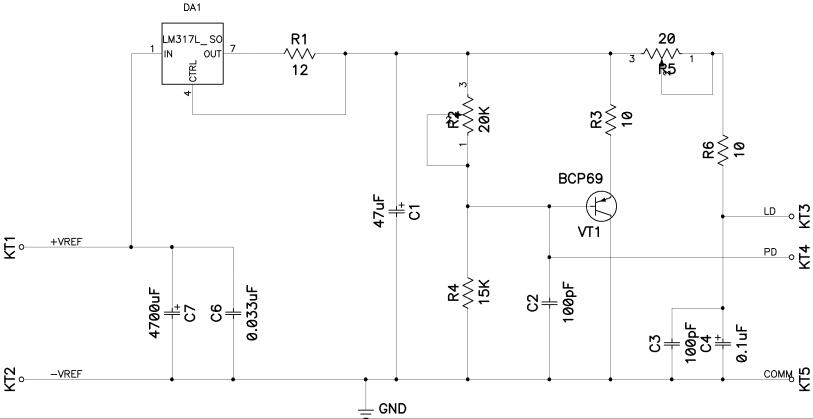
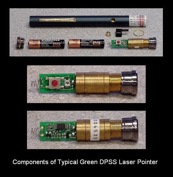
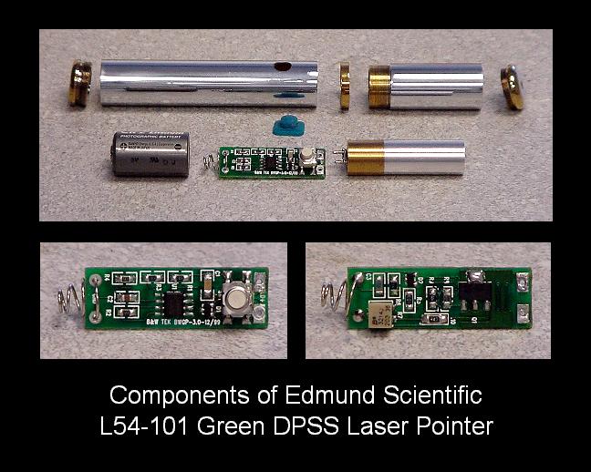
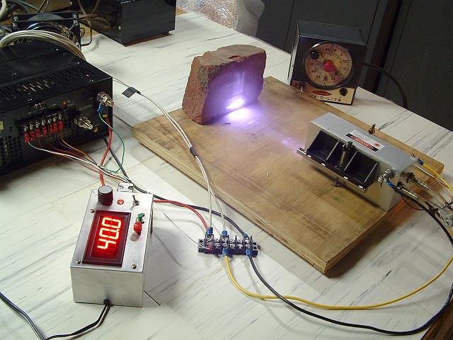
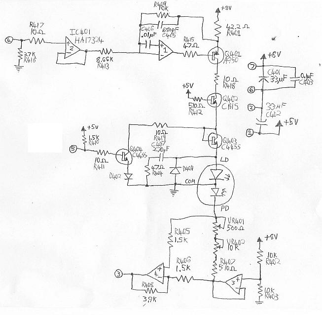
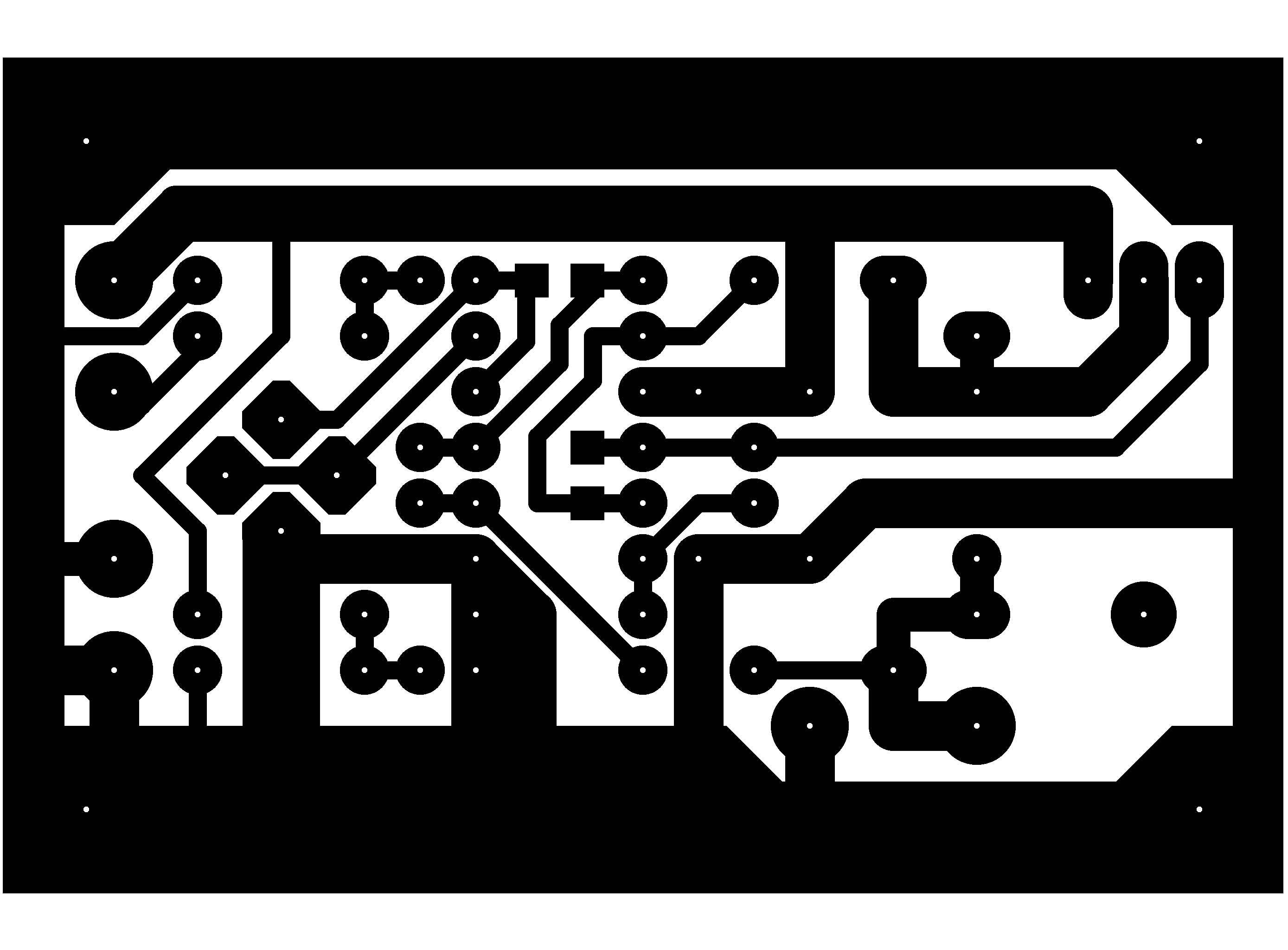