In almost all cases, these apply specifically to HeNe lasers operating on the so-called red transition around 633 nm (although when stabilized, there may be many many places to the right of the decimal point). HeNe lasers on other wavelengths can also be stabilized, though not all the same techniques can be used. This chapter deals almost exclusively with stabilized red HeNe lasers producing one or two linearly polarized single frequency components. There is some information on Zeeman lasers, though much more on their principles and characteristics can be found in the chapter: Commercial Stabilized HeNe Lasers mostly in the sections on Hewlett Packard/Agilent/Keysight stabilized HeNe lasers. HP practically created that industry, which still flourishes to this day and is likely to continue to do so for the foreseeable future.
General information on HeNe lasers as well as a brief introduction to stabilized HeNe lasers and typical locking schemes may be found in the chapter: Helium-Neon Lasers. Here, we delve into the topic in more detail.
However, it is not intended to be an all encompassing treatise on stabilized laser with all the gory details including hairy math. :) For that, refer to the scientific literature, most from the 1960s or 1970s. Only a few references are included here, but Web searches will turn up numerous research papers, many of which are in the public domain. For those that are not, affiliation with a major university or other academic institution may be required to access them for free.
The behavior of any laser is determined by many factors but the most important two are:
For the red HeNe laser, the gain medium is a mixture of helium and neon gases at low pressure excited by an electrical discharge. The helium helps with the excitation while the neon actually provides the gain. The 633 nm red wavelength is only one of several that HeNe lasers can use, but nearly all HeNe lasers that are actively stabilized are red. :)
For most stabilized HeNe lasers, a Fabry-Perot configuration is used with the gain medium between a pair of precisely aligned mirrors. These are all part of the sealed HeNe laser tube.
The useful output of most stabilized HeNe lasers is either a (ideally) single optical frequency, or a pair of optical frequencies separated by anywhere from a few 10s of kHz to hundreds of MHz. And in some applications, multiple frequencies (usaully 2 but it could be more) that are locked to a reference may be useful.
                                            Maximum     Optical       Optical
                                            Output     Frequency     Frequency
 Locking Type                                Power     Variation     Accuracy
-------------------------------------------------------------------------------
 Unstabilized multiple transverse mode     >200 mW       ---            ---
 Unstabilized single transverse mode        >50 mW      1.5 GHz        3x10⁻⁶
 Thermal stabilization                        2 mW       75 MHz      1.5x10⁻⁷
 Single mode Intensity stabilization        1.5 mW       10 MHz        2x10⁻⁸
 Gain peak stabilization                    1.0 mW        5 Mhz+       1x10⁻⁸
 Lamb-Dip stabilization                     0.5 mW        5 Mhz+       1x10⁻⁸
 Dual mode polarization stabilization       2.0 mW        1 MHz        2x10⁻⁹
 Three mode stabilization                   3.5 mW        1 MHz*       2x10⁻⁹
 Secord order beat stabilization            3.5 mW      200 kHz*       4x10⁻¹⁰
 Transverse Zeeman beat stabilization       1.5 mW      100 kHz*       2x10⁻¹⁰

 External (Iodine Cell) stabilization       0.2 mW       <5 kHz+      <1x10-11
 External (Iodine Cell) offset locked       2.0 mW       <5 kHz       <1x10-11
 External reference stabilization           2.0 mW       <1 Hz        <2x10-15
The useful output of these are NOT always absolutely pure single mode or single optical frequency limited by the laser dynamics:
* denote techniques where the output has either a pair of modes of similar amplitude close together in optical frequency, or a small "ghost mode" next to the main mode.+ denotes techniques based on Pound-Drever-Hall locking or a similar implementation that adds some dither to the optical frequency.
The approaches listed in the first group are intrinsic and use the Neon Gain Curve (NGC) of the HeNe laser tube as the reference. The center of the NGC has an optical frequency which depends only on the neon isotope ratio, temperature, and pressure, all of which can be controlled fairly precisely. The gain bandwidth of the NGC is also relatively narrow (as these things go) at around 1.6 GHz which can both limit the number of longitudinal modes that are oscillating (more on this below) and make feedback using its profile be more precise. Thus the NGC can be used to accurately position the lasing line(s) at a known location. All but the most exotic (and expensive!) stabilized HeNe lasers use one of the intrinsic techniques based on the NGC listed above. The vast majority use single or two mode polarization stabilization.
Relatively simple approaches using an external F-P resonator or other type of interferometer are possible. For example, using a low finesse Scanning Fabry-Perot Interferometer (SFPI) to monitor the longitudinal modes with a digital control loop maintaining them in a specific location on the NGC can be used with three mode polarization stabilization to obtain higher power with one mode centered. Single and dual mode polarization stabilization are limited to a maximum of around 2 mW; three mode stabilization is capable of up to around 3.5 mW or a bit more. But this is still an intrinsic technique. (This could also be used for single or dual mode stabilization but would probably not provide much, if any, benefit.)
It should be noted that it is because the gain bandwidth of neon is relatively narrow at 1.6 GHz, that the NGC becomes so useful. Solid state (SS) lasers on the other hand have lasing medium gain bandwidths typically wider by a factor of 50 or more. While straightforward techniques can be used to force single mode in an SS laser, achieving precise control of optical frequency with such a wide gain bandwidth is more difficult. This is one of the primary reasons that SS lasers have for the most part as yet been unable to replace the lowly HeNe laser in applications requiring optical frequency accuracy and stability. Locking diode lasers at a specific optical frequency is even more complex.
Of the extrinsic technigues, a stabilized HeNe laser making use of an iodine cell is probably the most precise optical frequency reference available commercially (with an equally high price to match). Its absolute optical frequency accuracy may be two orders of magnitude better than the technique of two-mode polarization stabilization, used in most commercial stabilized HeNe lasers now and in the past.
Going beyond this level of precision to high finesse F-P resonators and such is generally the perview of advanced research. To get down to that <1 Hz requires massive isolation chambers and active damping to minimize vibration and other external influences. Such a system is not likely to be portable! ;-)
The chart excludes any technques requiring use of intra-cavity devices like etalons to force single frequency operation. These are capable of both high power AND high stability but require special tubes and relatively complex control. Thus they are expensive and not at all common, though at least one company does claim to offer a 40 mW single frequency HeNe laser.
Having said all that, it's remarkably simple - almost trivial - to control the behavior of a common HeNe laser tube similar to those that used to be found in grocery store barcode scanners to provide a single frequency output with a stability of better than 1 part in 10,000,000. In fact, it can be done with a total of 4 parts costing only a couple dollars (besides the laser tube and power supplies). Nearly every possible technique imaginable has been explored at some time in the past. It's quite possible that trained pigeons have even been pressed into service for this purpose, and there's probably a patent on it. ;-) What are described here are only the most common (electronic) approaches.
But before any of these can be described in more detail, a primer or laser modes is required.
For everything that follows, it is assumed that the spatial mode structure of the HeNe laser is near pure TEM00 resulting in close to a Gaussian beam profile. We are not aware of any stabilized HeNes using multi-spatial mode tubes.
Lasing is determined by the round trip gain at the laser's optical frequency or wavelength, and resonance wihin the laser cavity. For everything in this chapter, we assume a linear "Fabry-Perot" cavity - the classic "gain medium between mirrors" laser - and the one used in virtually all HeNe lasers and even close to all stabilized HeNe lasers. But ring and other geometries would have similar constraints.
As with any resonant structure, there will be a fundamental frequency at which it can respond (n=1), as well as an inifinite range of harmonics (n=2,3,4.....infinity). For an organ pipe or violin string resosnance is at its fundamental and several harmonics. However, due to the short wavelength of light and relatively large resonant cavity length, for a HeNe laser, there is no fundamental and the harmonics have values of n in the hundreds of thousands or more.
In order to sustain laser oscillation, the round trip gain must exceed losses for photon at an optical frequency that is close to a cavity resonance as defined by n*c/2L. L is the distance between the mirrors, c is the speed of light, and n is an integer that results in the equation being equal to an optical frequency with a net gain greater than one for the lasing medium gain and cavity geometry.
For a red (633 nm) HeNe laser, the Neon Gain Curve (NGC) has a width of 1.5 to 1.6 GHz FWHM and is centered at around 474 THz. (We will have much more precise values later.) As an example, for a cavity length of 200 mm, c/2L is around 725 MHz. Thus, 1 to 3 modes may oscillate at the same time depending on their precise position within the NGC, but never more than that. Typical values for n in this case would be successive integers near 987,500. (There are other more subtle effects such as mode pulling and mode pushing that offset the actual optical frquencies by a small amount, but for now, the exact cavity resonances are sufficiently accurate.)
Higher power longer tubes will support more than 3 modes. And due to the shape of the NGC, the power in the strongest mode increases sub-linearly with tube length. So even if it could be isolated for a single frequency laser (which beyond 3 is not really practical), its power would not be that high, perhaps 6 mW for a tube outputting 35 mW . Further, due to mode competition, the power in each mode in longer tubes tends to fluctuate at random among them and stabilization doesn't help. This can be an issue even with the tube used in three mode stabilization.
When a HeNe laser is powered, whichever cavity resonances - also called "cavity modes" are within the NGC and have sufficient round trip gain will lase. These are the longitudunal or axial modes of the laser. Each of these "lasing lines" is a very nearly pure optical frequency in a HeNe laser, with a bandwidth of under 1 kHz and possibly as low as a few Hz or less. Thus, the term "single frequency" is appropriate (except for the most die-hard purists) where one of these modes is the output of a stabilized laser.
If the distance between the mirrors changes, the position of the modes will drift through the NGC. For large frame laboratory HeNe lasers, the resonator structure is designed to have a very low coefficient of thermal expansion. However, for common HeNe laser tubes of the type used in most stabilized HeNe lasers, the heating effects of the plasma discharge will cause the distance between the mirrors the change. As this occurs, the longitudinal modes will drift through the NGC. A mode at the high frequency-end will eventually disappear and be replaced by a new one appearing at the low-frequency-end. This is "mode sweep". An animation of the mode behavior of a tube similar to those used in many stabilized HeNes can be found at HeNe Laser Mode Sweep: 200 mm (~8 inch) Cavity Length. Of course, the movement is continuous but it's tiring to create an infinite number of slides. ;-)
To stabilize such a tube, the cavity length needs to be controlled in a feedback loop. A variety of means can be used to affect cavity length. A heater wrapped around the tube is most common, but others include an internal heater wrapped around the bore, an induction heater on one of the mirror mount stems, or the use of a PeiZo Transducer (PZT) behind one of mirror. It's even possible to use a magnetic actuator to press on one of the mirror mounts. With stabilization, the longitudinal modes can be precisely "parked" on the NGC. It's possible to do this in the animation by careful use of the left and right arrow keys to keep one mode centered. Fortunately, analog or digital electronics is much more effective and doesn't get tired as easily. ;-)
Note that while the NGC is discussed, it is actually the "Laser Output Power Curve" or LOPC that provides the input variables for most of these techniques. However, we may use the two interchangeably in discussions, even though purists will probably object. :)
Thin-film (Kapton) heaters are available from several manufacturers in a large variety of configurations, but may also be customized (at possibly significant expense) in terms of size, resistance, and temperature coefficient of resistance (which enables the actual resistance to be used to determine the tube temperature without a separate sensor). Thin-film heaters usually have an adhesive backing such that installation is very simple.
Wound heaters may be implemented using an appropriate size and length of copper "magnet" wire wound "bifilar style" to minimize the magnetic field produced by the heater current. This is more labor-intensive but acceptable for prototype or small production runs.
Where the tube structure that defines the cavity length is not made of a material like ZeroDur™, it would be difficult to use a PZT because the overall length would be changing by orders of magnitude more than a common PZT could accommodate. At the very least, the laser would have to use active temperature control and warm up for hours to reach thermal equilibrium before the feedback loop could be closed using the PZT. This is how the Spectra-Physics 119 laser was implemented.
PZTs have orders of magnitude faster response than thermal solutions, but generally require high voltage drive, which is an added complication. High bandwidth is not really a requirement for stabilized lasers unless modulation is desired. However, PZTs can easily provide a small dither with only modest voltages and have been used for this purpose in several stabilized HeNe lasers including the Nikon NKL-85 and Spectra-Physics 119, as well as iodine stabiilized HeNe lasers built by NIST and Frazier, among others.
For a very basic implementation, (1), (2), and (4) can be done manually, though most systems use either a temperature sensor, some type of timing of mode sweep, or simply a fixed delay to determine when the laser is ready. Actual locking (3) may use a variety of electronics from simple to complex, a microprocessor, or a combination of the two.
Before the availability of inexpensive microprocessors in the early 1980s or thereabouts, controller implementation consisted of TTL or CMOS ICs for logic and timing along with op-amps for the actual feedback loop. (Or discrete transistors or vacuum tubes before that!) These were effective, inexpensive, and easy to repair should the need arise. But as time went on, the parts that were used have become harder to find. At least one company, Agilent, came up with an intermediate solution using a Field Programmable Gate Array (FPGA) that essentially replicated a large portion of the discrete logic in a single chip. And engineers just can't resist redesigning perfectly satisfactory systems. ;-) Nowadays, a dirt-cheap single chip microprocessor or microcontroller (same thing) is the solution of choice, with at most a few analog parts to condition the input signals.
So, most stabilized HeNe lasers that are not legacy products from the 1980s or before use a microprocessor to perform most logic, timing, testing, and control functions, though some may use a purely analog implementation for actual locking using the feedback loop to reduce noise in the control signals that could end up modulating the optical frequency. For most users, this is not a problem. But as an example, the Melles Griot 05-STP-901 and functionally identical Spectra-Physics 117A which date from the early 1980s or before used Pulse Width Modulation - PWM - to drive the heater wrapped around the tube. (Many modern microprocessor-based implementations including µSLC1 use PWM as well.) Very finicky users have detected the residual ~5 kHz PWM in the laser's optical frequency and complained. This would probably only show up if the output of a laser like this were beat - combined so that a difference frequency could be detected - with the output of another laser and the result displayed on an RF spectrum analyzer or similar instrument. A trivial change to the electronics can convert the PWM to a purely linear control loop. With a microprocessor, switching to a Digital to Analog (D/A) output instead of PWM would also greatly reduce digital noise in the feedback loop.
The benefits to the user of a microprocessor-based controller are in flexibility, reliability, and cost. The benefits for the manufacturer also include the system now being proprietary - user repair, among other things, is virtually impossible because the smarts are in the software/firmware, which is generally not made available to anyone outside the company or their authorized service organization. If a TL084 op-amp went belly-up in an SP-117A, basic troubleshooting techniques could be used to repair it. Or if the laser tube required replacing, there were three trim-pots to perform all adjustments. With a similar modern laser, repair of all but the most obvious problems like a bad DC power supply or blown fuse is virtually impossible. In some cases, replacing the tube requires access to firmware parameters to set various constants. Even identical model HeNe laser tubes (assuming one is avilable) may differ in the output power of the waste beam from the back of the tube - which is often used for the feedback. There may be workarounds by adding a PCB with adjustable op-amp circuits to fake the signals derived from the tube to match what the firmware expects, but these are not ideal solutions. There is a silver lining for the user though - it's impossible to break anything by opening the case and twiddling adjustments because there are none. (Although that's not always strictly the case, as with µSLC1 where the coarse mode gain adjustments are trim-pots!)
Having said all that, any new stabilized HeNe IS going to use a microprocessor for the bulk of the controller, with perhaps an analog section for the actual feedback loop. Being able to tune the control loop by changing parameters rather than soldering components or even adjusting trim-pots is just far superior for development and maintenance. However, there will then generally be NO User Serviceable Parts inside. ;-)
      Cause             Sensitivity       Comments
 ------------------------------------------------------------------------------
  Helium Pressure      +22 MHz/Torr       Pressure of He decreases with use
  Neon Pressure        -25 MHz/Torr       Pressure of Ne decreases with use
  Neon Isotopic Ratio  +10 MHz/% of 22Ne   Ratio of 22Ne:20Ne Decreases with use
  Temperature          +280 kHz/°C        Affected by specific lock point
Under normal conditions, the changes in internal pressure are likely to be much less than 1 Torr and temperature itself has only a small affect on the gain center. The major one is gas fill ratio of 22Ne:20Ne. This is of course determined at the time of manufacture (and may not be that accurate), but will also decline slightly with use as 22Ne will be trapped at a slightly a higher rate than 20Ne.
Another (and perhaps even more important) effect of the isotope ratio is that is impacts the effective width of the NGC. For common (non-stabilized) HeNes, using a 1:1 isotope mix is beneficial as it allows a higher number of longitudinal modes to oscillate resulting in higher power. But for stabilized HeNe lasers, it may be desirable to minimize the NGC width to reduce uncertainty in the optical frequency when locked. And for axial Zeeman stabilized HeNe lasers, it may both increase available power (since the lasing modes are close together) and increase the magnetic field at which rogue modes appear.
One way to assure that the tube itself runs at a relatively fixed known temperature is to warm it up to a set-point temperature rather than using an indirect method like the rate of mode sweep to determine when to lock. And then to fine tune that after awhile to give everything time to reach thermal equilibrium. Once locked in this manner, the temperature of the tube will remain relatively constant. To improve it even further, at least two companies (Lab for Science and MicroG) put the tube (with its heater wrap) in a temperature-controlled housing. Most do not.
More on this may be found in the chapter: Commercial Stabilized HeNe Lasers.
For axial Zeeman lasers, there should be two orthogonal components each of which is single frequency, but differ by the split frequency. Since the split frequency is never higher than around 8 MHz, this can be checked with a fast photodiode behind a linear polarizer at 45 degrees to the polarization axes and an oscilloscope or frequency counter.
For axial Zeeman lasers, they will be two close together to resolve with most SFPIs, but by using a linear polarizer to selectively block one or the other, their amplitudes can be tested.
The relevant parameters will be the longitudinal mode spacing, maximum amplitude of the a single mode (isolated with a linear polarizer if necessary), and the estimated shape and width of the NGC. An SFPI can be used to determine the lock point and the NGC parameters. An estimate of the slope at the lock point can then be made and used to calculate change in optical frequency versus amplitude. Depending on the time scale of interest, either a laser power meter or biased photodiode and DMM, oscilloscope, or data acquisition system can be used to make the measurements.
Most of the following requirements are common to all of the intrinsic stabilization techniques. Any specific ones will be noted.
Nearly all red HeNe laser tubes are specified to be TEM00 since most applications require that they be single spatial mode.
Very short tubes may be locked with single mode output over a modest range even if they are not random polarized. Some older lasers used tubes with Brewster windows, which are inherently polarized. But techniques like Lamb Dip and gain peak locking can still be effective, as well as simple intensity locking. However, modern stabilized HeNe lasers using intensity locking are likely to use short random polarized tubes.
Unless the tube manufacturer guarantees a specific model tube is well behaved, it must be tested prior to use in a stabilized laser.
Fortunately, Murphy must have taken a day off for the red HeNe laser. Due to non-linear aspects of mode competition, adjacent modes in the red (633 nm) random polarized HeNe laser are nearly always orthogonally polarized. This is not generally true by default for other HeNe wavelengths, though it can sometimes be forced with a weak magnetic field or by other means, but such techniques can be tricky and unreliable. Since the 633 nm wavelength is capable of the higher power, obeying this rule is fortunate. It would have been nice though if Murphy hadn't been so selective. ;-)
Some model tubes are spec'd to be "non-flippers" or have "non-mode flip optics". For some manufacturers, this really means testing and selecting those tubes that qualify. Others have the manufacturing process controlled well enough to guarantee it without sorting. And one company (REO) has a patented funky resonator mirror configuration for this purpose (but even they don't always get it quite right). If not a part of the tube specification, then some samples may be suitable but not all. However, if a tube tests as a non-flipper over the temperature range where it is being used, it will probably be satisfactory as this behavior doesn't tend to change with use. But some tubes start out as flippers when cold and then settle down after warmup, which would be acceptable. And with clever design, even many flippers can be used in stabilized lasers as long as they can be locked at a point away from where they flip. Of course, as an end-user of tubes, testing tubes and having to throw away a large percentage of unsuitable expensive tubes could be a strain on job security. :)
Tubes suitable for any of the stabilization techniques are usually short enough that rogue wavelengths are extremely unlikely.
Where multiple modes are present when the laser is locked, all of them may be used as output. Specifically where 2 modes are present, the laser may be set up to produce a beam with two optical frequencies separated by approximately the longitudinal mode spacing of the laser tube simply by not blocking one of them. Since the locking techniques do not change for these, they are not coveered separately.
In the chart above, there is an entry for multiple transverse mode (non-TEM00) lasers. While technically, the lasing modes are all within the NGC and thus limited to a gain bandwidth of 1.5 or 1.6 GHz and thus around 3 ppm, as a practical matter, their relative optical frequencies is for all intents and purposes, unpredictable. So, using such a laser as a reference for anything could be....interesting. Thus, there are no values given for the optical frequency variation or accuracy.
For the unstabilized single transverse mode laser - which describes most red HeNe lasers that aren't stabilized - there will be multiple longitudinal modes but they will be separated by approximately the cavity FSR or c/2L. Coherence length (or period) is thus predictable, if short compared to single longitudinal mode stabilized lasers. However, as the length of the tube and output power increases, the modes become much less well behaved due to mode competition. The relative amplitudes of the modes tends to change at random with only loose regard for the profile of the NGC.
While there is no active feedback based on the NGC, a human must set the mode position based on the NGC, so it is still intrinsic. ;-)
Any HeNe laser tube suitable for a stabilized HeNe laser can be controlled in this manner. Depending on tube size, a 1 °C change in tube temperature will change the mode position by a few hundred MHz or more due to the change in distance between the mirrors. So temperature control is required to a small fraction of a degree. But this is not difficult even with the electronics that was available in the 1960s.
However, to truly reduce the uncertainty so as not to require the user to fiddle with the thing, some form of optical feedback is needed.
A random polarized tube is generally used since over a large portion of mode sweep, even a relatively short tube will actually produce 2 modes. For use with random polarized tubes, a polarizing beam splitter blocks the unwanted mode and a non-polarizing beam sampler diverts a small portion of the output beam to a photodiode to be used for locking feedback. Or if both modes are desired in the output, the mode used for feedback can be diverted using a beam sampler, or taken from the waste beam at the back of the laser.
To provide the ability to move the lock point over a large portion of the LOPC with no possibility of a third mode popping up, the tube must have a cavity length of less than about 200 mm.
Short polarized tubes could also be intensity-locked, though it's not clear why this would be desirable: There is no advantage to using a polarized tube in a single frequency laser with a serious limitation in output power since the tube has to be short enough so that only a single mode is lasing when locked as the unwanted mode cannot be removed with a polarizer.
The only purely single mode stabilized HeNes I am aware of are the Aerotech S100 which morphed into the Melles Griot 05-STP-91x series. These are NOT microprocessor controlled. ;-) Although newer versions of this laser actually have hooks in place to support conversion to a dual mode stabilized laser by adding a photodiode and changing a jumper, this is not publicized. :) The 05-STP-91x lasers lock on the side of the LOPC using a novel induction heating approach originally developed by Aerotech. This is compact and allows for fast time-to-lock, but the more conventional heater wrap can also be used. More info on these lasers may be found in the section: Aerotech Stabilized HeNe Lasers.
Most dual mode stabilized HeNe lasers have a user selectable option (switch, jumper, or logic input) to lock to a single mode. These are described below.
Dual mode polarization is by far the most popular technique used in commercial stabilized HeNe lasers at the present time. It is also the only common approach offering the highest power in a pure single longitudinal mode (single optical frequency). With a lively tube, this can be 2 mW or more in a single mode when the modes are balanced. For greater power, they can be offset somewhat with either frequency or intensity stabilization providing up to 2.25 mW or even more in a pure single mode. (However, 1.5 mW and 1.75 mW, respectively, are more typical in stock tubes unless specifically selected for high power.) The limiting factor is either where a third mode appears, or where the output mode approaches the center of the NGC. To get higher power without fancy and expensive additional complexity like an intra-cavity tuned etalon requires going to three mode stabilization. But then the output mode is never quite pure regardless of locking technique. For many applications a few percent of unwanted amplitude or frequency modulation may be acceptable.
Laboratory lasers using dual mode polarization stabilization often also have optional intensity stabilization selected by a switch, logic level, jumper, or software, where one of the modes is locked to a reference level rather than the two modes being compared. A means of changing the reference level may also be provided. There will still be only a single mode present (when the other one is blocked) over a fairly wide range of optical frequencies on either side of the point where the two modes are equal so that the output intensity can be adjusted up or down. Specifically, with intensity stabilization, it may be set up to output somewhat higher power.
The tradeoff is that the optical frequency accuracy and stability is better when both modes are used, but at the expense of intensity stability. But the intensity stability is better using the single mode.
However, it is not without drawbacks. These are related to mode purity and long term absolute frequency drift. When three modes are lasing in a HeNe tube, there will also be three relatively weak "ghost" modes very close to the lasing modes. There are caused by third order non-linear dynamics. The difference in optical frequency between the ghost modes and lasing modes of a up to a few hundred kHz is exploited by second order beat stabilization for locking (but not for the other techniques). There is no practical way to remove the ghost mode associated with the centered (main) mode from the output. So, strictly speaking, the output of these lasers is not truly pure single mode. In addition, to maximize output power, it's possible that some tubes may have small 4th and 5th normal lasing modes present 400 to 500 MHz from the closest desired lasing modes. Both of these are typically under 5 percent of the amplitude of the output, which could be acceptable for many applications. Two mode stabilization does not suffer from either of these issues except during warmup when three modes may be present during part of mode sweep. This is generally of no consequence to the ultimate application unless the laser is used during this period. So these two potential issues should be kept in mind in determining if the increased output power provided by the three mode techniques outweighs the presence of extra low level modes.
A well behaved random polarized single transverse mode (TEMOO) HeNe laser tube 13 to 14 inches in length can provide 3 to 4 mW in a nearly pure single mode if it is centered on the LOPC. (As above, "well behaved" means that adjacent modes are orthogonally polarized and it is a non-flipper.) Two modes of the opposite polarization will straddle it and can be blocked in the output beam with a polarizer. Ideally, there will not be any other modes present. The next two ones would be just beyond the tails of the NGC. However, if the tube is very lively or a bit too long, they may poke their heads up and result in weak rogue modes that cannot be eliminated because they will have the same polarization as the desired centered mode. If the tube is shorter, those weak modes can be guaranteed to disappear entirely, but with a sacrifice in output power. So, it's a tradeoff of output in the dominant mode versus the rogue weak ones. For many applications, a few percent in modes almost 1 GHz or more away from the dominant made is acceptable. However, for some stabilization techniques, the additional modes, even though weak, may introduce noise in the locking signal. The ramafication so of this are left as an exercise for the student.
Suitable tubes for three Mode stabilized laser should include the Melles Griot 05-LHR-150, Siemens/LASOS LGR-7627, and JDSU 1125 as long as they are confirmed to have well behaved modes - they are not bouncing around due to mode competition and are not-flipping polarization. Nearly all red (633 nm) HeNes satisfy the requirement for adjacent modes to be orthogonally polarized. All three types should be available new or surplus. The older Aerotech OEM5R may also be suitable. These are all rated 5 mW but new samples may have much more power output up to 8 mW or more.
Three approches to three mode stabilization are discussed below. The simplest one overall is probably second order beat stabilization and has the potential to provide the best optical frequency stability.
But whether it is worth going to any of these more complex, more expensive, and physically larger schemes for a benefit of few tenths of a mW will depend on the application. As a practical matter, to guarantee that the rogue mode amplitude will be minimal, at most 3.5 mW will be available in a single (mostly) pure mode. And to accomodate variations in tube performances, it may be closer to 3.0 mW. Consider that the slightly shorter tubes for dual mode polarization stabilization can be spec'd to 4 mW or more. I've measured output power from tubes that were not brand new as high as 4.5 mW. But even at 4.0 mW, the balanced lock point would be 2.0 mW. And by offsetting the lock point slightly, 2.25 mW or even slightly greater power may be available in a single pure mode with a simpler more conventional system.
In addition, when designed for maximum power, there will be little to no tunability of optical frequency - the output mode MUST be centered on the NGC. Where tunability is a requirement, three mode stabilization can still be used, but maximum output power will be somewhat lower, and will vary with the lock point. However, it will then provide higher power from a tube otherwise suitable for dual mode stabilization since the region at the peak of the NGC will be usable.
The HeNe laser tube requirements are basically as discussed above, where (ideally) at most 3 modes can oscillate when one of them is centered on the NGC. In the diagram, the tube length is such that this requirement is met. If one is willing to accept a small amount of output on the two additional modes that would be present with a slightly longer tube, or one that is livelier, then a bit more power in the centered mode may be possible. However, the rogue modes will result in additional low level beat signals which may result in locking problems. Thus, assuring the tube is pure 3 modes is desirable, at least until the basic design has been tested. This can be often be accomplished on a lively or slighty too long tube with little loss of power by carefully slightly misaligning the OC mirror.
When a HeNe laser is oscillating with three longitudinal modes, there will be primary difference frequencies corresponding to the distances between the lasing modes, and secondary difference frequencies between pairs of primaries. While the primary difference frequencies differ by approximately the longitudinal mode spacing of 400 to 500 MHz for this length tube, the secondary difference frequencies are in the hundreds of kHz range and easily detected and used as the locking variable. Note that if there are rogue 4th and 5th modes oscillating, there may be other primary, secondary, and tertiary difference frequencies to contend with.
A paper describing the use of the second order beat for stabilizing a HeNe laser is: "Frequency stabilized HeNe gas laser with 3.5 mW from a single mode", Jonathan D. Ellis, Dirk Voigt, Jo W. Spronck, Ad L. Verlaan, Robert H. Munnig Schmidt, Elservier, Precision Engineering, 36(2012), pp. 203-209.
From the paper:
"When nearly symmetric in the HeNe gain profile, the three mode laser contains three additional low power modes. The three additional smaller modes arise from third-order non-linear harmonics and their exact frequency difference with respect to their nearest adjacent mode depends on cavity tuning and the excitation state of the active medium. In this work, the frequency difference between a smaller mode and its main mode, vb, ranged between 200 kHz and 550 kHz. The three main modes from lowest frequency to highest are v1, v2, and v3 and the three smaller mode frequencies are (2v2-v3), (v1+v2-v3), and (2v2-v1). Alternative expressions for the three smaller modes are (v1+vb), (v2-vb), and (v3+vb), respectively."
Since the frequency of (v2-vb) will be in the range of hundreds of kHz and a strong function of center mode position on the NGC, it can be used for locking.
The only known commercial stabilized HeNe laser that is known to have employed the Second Order Beat (SOB) locking technique was the Laboratory for Science 260. Only about 10 of these were ever manufactured and can you believe it, I have not seen a single sample. :( :) The LFS-260 dates from the late 1980s or early 1990s and used a Phase Locked Loop (PLL) IC to lock the beat to a crystal controlled frequency synthesizer. This still may be the approach with the best precision and stability, but nowadays a microprocessor can do almost as good a job with much more flexibility. I suppose LFS didn't publish to (1) keep the technology proprietary and (2) so others wouldn't think they were nutcases. :)
Here is the theory of operation from the LFS-260 brochure:
"In a laser with three TEM00 modes, there will be two primary beat frequencies corresponding to the difference frequencies between the central mode and each of the modes on either side of center. These two beat frequencies, typically in the range of 400 to 500 MHz, will in general not be exactly the same because the frequency pulling effects on each mode will vary with the differing slopes at the respective operating points on the Doppler gain curve. The difference between these two beat frequencies will yield a third or intercombinational beat frequency typically in the range of 100 kHz. In an integral end mirror tube, where the alternate modes are orthogonally polarized, the intercombinational beat frequency will not be zero even when the central mode is at line center because of the birefringence of the mirrors. In the Model 260, the laser tube is preselected not only for power but also for an appropriate range in the intercombinational beat frequency. The median frequency is then tightly phase locked to the frequency of a crystal controlled frequency synthesizer. "
In HeNe Laser Using Second Order Beat Frequency Stabilization, the tube length is such that only three modes can oscillate when one of them is centered on the NGC. If one is willing to accept a small amount of output on the two additional modes that would be present with a slightly longer tube, or one that is livelier, then a bit more power in the centered mode would be possible.
The Black Hole is supposed to capture every last photon of the undesired modes. (LFS called their version a "black etalon", but I think black hole better captures the spirit of its function.) However, something more easily obtained will suffice, just as long as it doesn't reflect back into the laser. ;-)
The above paper uses a photodetector sampling the output polarization to obtain the beat signal for use in locking. In my initial tests using a Melles Griot 05-LHR-150 tube, there was a strong beat present at the lock point when taken from both the output polarization (centered mode) and blocked polarization (outer modes). So it may also be possible to use the blocked polarization since it contains the outer modes. In that case, the Black Hole would need to be moved to after the beam sampler. I hope it doesn't weigh too much. :) However, the paper suggests that this may have more non-linearities in the locking signal. There's a lot going on here, some of which may not be intuitively obvious.
The exact beat frequency where the lasing mode is centered is not the same for each tube sample due to differences in parameters like mirror birefringence and orientation, this would need to be tested and entered as a constant into the firmware or PLL synthesizer. The correspondance of lock frequency to aboluste optical frequency depends on many factors. While LFS claims locking parameters in the model 260 don't change much. this may not be entirely true. For example, the lock point for the same absolute optical frequency is a strong function of tube (gas) temperature and pressure. So the exact lock temperature and tube aging will affect them. And maintaining the same optical frequency may impact the output power if it moves off from center on the NGC.
The locking variable is the second order beat frequency. This typically a few hundred kHz in amplitude modulation depth of between 0.5 and 5 percent of the power in the centered mode. Extracting it and converting to a TTL signal is not entirely trivial, expecially where it is desired to minimize reduction in the usable output power. Ideally, it should be taken from the waste beam which has a typical single mode power of only around 25 µW, resulting in a DC photodiode current of around 10 µA and an AC signal of under 1 nA. The detector circuit would require careful analog design using low noise construction techniques. For my prototype, I am sampling the output beam with a glass plate and using an HP/Agilent 10780A, which has barely enough sesitivity even with the 300 µW available there. It would not work at all using the waste beam. (The 10780 has no problem with under 10 µW when used in its normal application with HP/Agilent two frequency HeNe lasers, but then the useful signal is 25 to 50 percent of the total power, not under 5 percent or less.)
In addition, any ripple in the HeNe laser power supply also modulates the amplitude of the laser's output, and it may have similar or greater AC amplitude as the second order beat. If the DC current is set optimally, the dominant contribution of the ripple frequency will be at twice the power supply switching frequency. In tests, it was necessary to add an external ripple reducer to the standard Melles Griot 05-LPL-902 power supply for the 05-LHR-150 laser tube and another stage might be desirable. While the typical switching frequency is below the expected beat frequency and the optical receiver can filter this to some extent, strong harmonics will still be present, especially that second harmonic. A fully analog supply would be suprior with additional filtering of both the DC rail (to eliminate ripple at the AC line frequency and its harmonics) and ripple reduction in the output (to suppress zener noise/plasma oscillation ripple).
The controller would need to warmup the tube as with other more mundane locking techniques, and then use the a value derived from the difference between the reference value and actual second order beat to drive the heater. Since the relation of beat frequency to mode position and absolute optical frequency is a strong function of tube conditiona (internal temperature and pressure), it may be best to use tube temperature to determine when to turn on locking, rather than some measure of mode sweep rate or count.
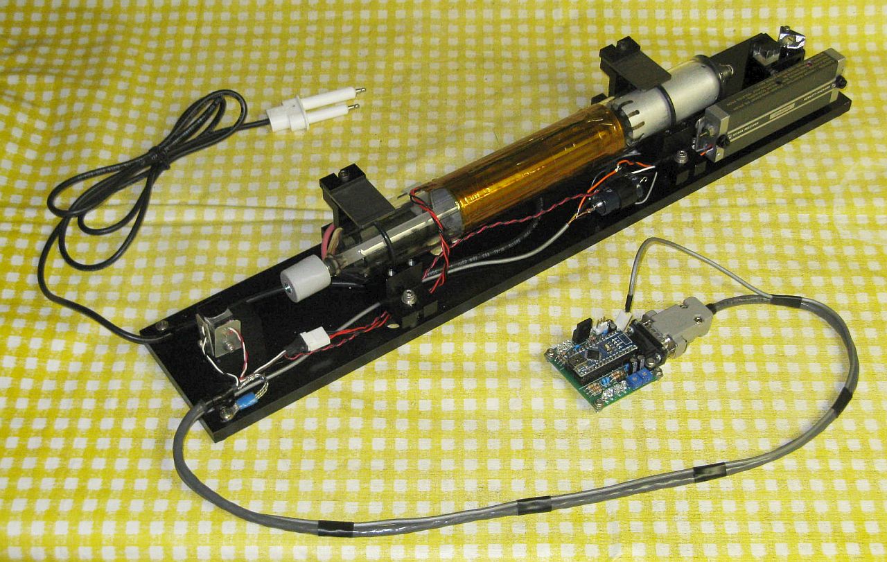
I am in the process of building a system of this type using a variation on the µSLC1 controller, µSLC2. A diagram is shown in in Three Mode HeNe Laser Using Second Order Beat Stabilization and a photo in Prototype Three Mode Stabilized HeNe Hardware with µSLC2. This provides both the P and S mode signals from the back of the tube and the beat signal using a modified HP 10780A optical receiver sampling the output beam. Using the output beam was done out of convenience since even sampling only 10 percent of it has much higher power than the waste beam and even then, the 10780A is barely sensitive enough.
Stay tuned.
To summarize some of the major issues:
So there's a lot going on here compared to the traditional dual mode laser. (Much of this applies to any three mode laser, not only one using second order beat stabilization.)
However, (1) the modes do not change in amplitude by very much - perhaps 5 to 10 percent of the total power and (2) the lock point will NOT be where their amplitudes cross as with the dual mode stabilization, but rather where one is maximum and the other is minimum, and they are nearly constant in these locations. Therefore, a simple comparator cannot be used. Rather a technique that locks to the peak or valley of a function of the mode signals is required. One is called Pound-Drever-Hall locking. Essentially, the cavity length is periodically dithered by a small amount and the laser is locked to a zero crossing of the 2nd harmonic of the mode signal. This sounds hairier than it is. A microprocessor can do it in real-time and electronic systems and even ICs exist for various applications. They are called "lock-in amplifiers", "synchronous demodulators", or "phase sensitive detectors.
As noted, a microprocessor can also implement PDH locking. For something inexpensive like the Atmega Nano 3.0 used in µSLC1, the dither frequency would need to be limited to a few hundred Hz. Although dither frequencies of a few kHz have typically been used, this should be adequate.
Hardware is similar to that of seond order locking, but with no need for the beat detector. A photodiode is needed to monitor one of the polarized mode amplitudes to be used as the PDH variable, but monitoring both will provide double the signal-noise-ratio. There would also need to be some means of dithering the cavity. A suitably designed heater may have enough bandwidth if driven with a high level AC signal on top of the one for maintaining cavity length, but if not, then an electromagnetic (voice coil or solenoid) could be attached to act on one of the mirror mount stems. This dither will show up in the output as modulation of the optical frequency (along with the second order beat signal).
It's not likely that PDH locking would provide any real advantage compared to either of the other approaches and using the second order beat is probably simpler.
Nearly all red HeNe laser tubes are specified to be TEM00 since most applications require that they be single spatial mode.
Depending on the strength of the magnetic field, most practical lasers require the cavity length to be limited to 125 mm (~5 inches) or less. Otherwise, "rogue modes" may be present which can result in problems in an interferometer and/or prevent locking at all. And even shorter tubes provide more flexibility in selecting the "split" or REF frequency, but they suffer from lower power. Nonetheless, tubes with cavity lengths as short as 81 mm (~3.2 inches) have been used in commercial axial Zeeman lasers with acceptable output power, specifically the Zygo 7705. And a 102 mm (~4 inch) cavity length is used in current production Keysight 5517 lasers.
HP/Agilent/Keysight tubes tend to have quite random mode behavior without a magnetic field. However, common barcode scanner HeNe tubes which may have well behaved polarization can sometimes be used, though those that are flippers tend to be better. At least one company now manufacturs a series of tubes suitable for use as replacements for the tubes in HP/Agilent/Keysight lasers.
There are a few variations. Most HP/Agilent/Keysight lasers use a clever implementation with a single photodiode behind an LCD polarization rotator and polarizing filter that alternately samples the H and V polarized modes. Sample-and-hold circuits capture the values and these are what are used to control the feedback loop. This approach is largely immune to drift in the electronics over the life of the laser tube. The Spindler and Hoywer ZL-150 is the only known axial Zeeman laser that does not use dual mode polarization stabilization, but rather mechanically dithers the laser tube cavity length and locks to the point where the split frequency is a maximum.
Note that locking to a specific split frequency using a PLL or similar technique is generally NOT recommended as its exact value depends on many factors including the power output of the tube and local magnetic fields. As the tube ages with use, power output generally declines and the splite frequency increases. Any external magnetic fields - even the magnetized base of an optics mount or another similar Zeeman laser - will change the split frequency. So, the laser may not remain at the center of the split gain curves as desired.
However, there is, as always, a catch. ;-) Although the papers talk about a single mode, it's actually a pair of closely-spaced H and V compoennts using the same cavity mode, similar to the axial Zeeman laser but generally with a much smaller frequency difference in the 10s to 100s of kHz range. For many applications, a coherence length of a mile is still adequate. :) Of course either of the H and V components can be separated out with a polarizer, but then the power is cut in half.
When I found the first reference, I thought it really meant pure single mode greater than 5 mW. Nope, must read the fine print. :( :)
Reference: Robert J. Knollenberg, "Prospects for the Helium-Neon Laser Through the End of the Century", SPIE Vol. 741, Design of Optical Systems Incorporating Low Power Lasers (1987). The paper mentions it briefly, but has two other references, 17 and 18 which should be more detailed. (This paper also describes the original HP axial Zeeman laser and doesn't get it quite right, unless it's a prototype that documented anywhere.)
There were at least two commercial transverse Zeeman stabilized HeNe laser. The most well known (to me at least) is the Laboratory for Science 220. And, yes, I have two working samples of this laser. ;-) The only one I know of (at least in a product blurb) is the NEOARK NEO-262.
The feedback is implemented with a low finesse SFPI using the waste beam behind the HR mirror. The low finesse results in spread out peaks, but these are better to analyze because they can be averaged and are then less sensitive to the exact position of the digital samples. As a result, to reduce the space requirements for the SFPI using available mirrors, a sub-confocal spherical or hemispherical SFPI cavity can be used with an FSR larger than the neon gain bandwidth and a mirror spacing of under 1 cm.
To simplify computing requirements, a dual polarization SFPI detector can be employed. Then the orthogonally polarized modes will be separated resulting in unambiguous determination of the polarization of the modes of orthogonal polarization orientation. However, for a dual polarization detector to be effective, the SFPI mirrors must either have zero birefringence, or their birefringent axes must be aligned with the tube's polarization axes. Otherwise, the mirror birefringence will overwhelm the polarization of the modes.
As with any HeNe laser, back-reflections must be minimized to the maximum extent possible by orienting the optics such that direct reflections back into the tube are prevented. Thus the PBS should be at a slight angle and the SFPI should be offset and have an aperture as shown in the diagram so that the internal reflected beams do not re-enter the laser.
A polarizing beam-splitter at the front of the laser both selects the desired polarized mode for output and provides feedback to monitor laser power since doing that through the SFPI may not be consistent. Although the sampled power is of the blocked mode(s), not the output mode, the output power can be inferred since their relative amplitudes can be determined by the firmware. If preferred, a non-polarizing beam sampler could be added to obtain the amplitudes of both polarized modes. But that would reduce output power slightly.
The locking algorithm would have the same general state structure as for the single and dual polarized mode locked except that the error terms will be determined by analyzing SFPI data in real time to center a mode of the desired polarization. Thus a microprocessor with higher performance including a higher A/D sampling rate may be desirable.
Note that this is NOT quite the same as using an external reference for locking. (More on that below.) It's still an intrinsic method using the NGC as the reference. Thus, while drift in the SFPI due to temperature changes or whatever is still a consideration and will impact the locking algorithm, it will not affect he ultimate performance in terms of absolute optical frequency accuracy or stability.
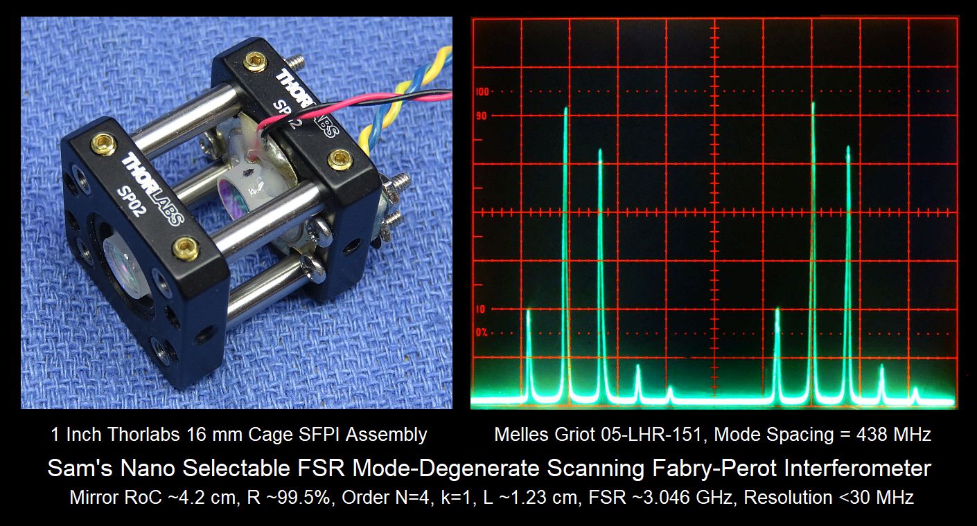
As a proof of concept, an SFPI like Sam's Nano Selectable FSR Mode-Degenerate Scanning Fabry-Perot Interferometer should be ideal for a prototype and doesn't require really small RoC mirrors. The spacing as shown is 1.23 cm, but there are resonances with smaller spacings. And of course it doesn't need to be built with fancy Thorlabs parts. ;-) The Mini Laser Mode Analyzer 1 (V1) or Mini Laser Mode Analyzer 1 (V2) could be adapted as the controller with additional code to locate the peaks of the SFPI display and output a heater control voltage based on their amplitude, though a faster platform would be desirable for an actual system. There's a small chance that something along these lines will be implemented and/or offered as a kit of parts.
However a normal internal mirror HeNe laser tube cannot be used since (1) locking requires the use of the PDH technique involving dithering the cavity length and (2) the dip in power due to these lines is only about 0.15 percent. At least that was the thinking of the designers of these lasers in the 1980s. Dithering is possible. In fact, as noted, it may occur inadvertently due to the heater characteristics. And a special heater could be designed that maximizes rather than minimizes this vibration. Dither could also be introduced by a mechanical means such as a voice coil positioner attached to one end of the tube. This was in fact done for an axial Zeeman laser, the Spindler and Hoyer ZL-150. so a higher power than can be provided by a single freqeuncy HeNe laser is required. Getting enough power is perhaps more of an issue. The solution generally used was to place the iodine cell inside the laser cavity where a HeNe laser tube with two Brewster windows was used as the gain medium. Putting the iodine cell inside the cavity can take advantage of the higher circulating power there AND there would be an amplification effect on small changes in absorption not present if simply put in a beam with a single pass. And PZTs on one or both mirrors would then be able to easily dither the cavity length for the PDH locking, as well as changing it by a larger amount to select the lock point. But going intra-cavity creates problems of its own. Specifically that to accomodate the length of a two-Brewster tube with enough power to be useful AND the iodine cell, the total cavity length needs to be more than 300 mm. It is actually around 350 mm for the Frazier version. And as we know from previous discussions, such a long laser will NEVER be single frequency (one mode oscillating, required for the ISHL) unless special means are taken to force it to be so. One method that has been used in these lasers is to introduce sufficient losses that only a single mode has enough gain to lase. This cam be accomplished by using a very low reflectivity output mirror - only 93% reflectance in the original NIST paper. However, deliberate misalignment of the Brewster orientation of the laser tube and I2 cell would work just as well and provide a means of increasing power as the tube ages. And tests of a ISHL resonator similar to the one used by Frazier confirms an OC reflectivity of between 0.99 and 0.994 percent. Its Radius of Curvature (RoC) is around 60 cm which is long enough to have no impact on longitudinal mode selection with the planar HR. The downside of any approach using such a long cavity is than when designed or adjusted so only a single longitudinal mode can oscillate, the available output power from the laser is order of only 100 µW! Anything higher and there will be another mode present which cannot be removed inside the cavity. To obtain higher power, one technique is to "offset lock" a conventional stabilized HeNe laser to the ISHL. While strightforward, this does of course add complexity and cost.
Some straightforward modifications would enable the cavity to be somewhat shorter as well as simplifying maintenance. Substituting a one-Brewster 05-LHB-270 for the 05-LHB-290 would eliminate one Brewster window and the external HR mirror, both of which can collect dust and other contamination, as well as the additional losses from the inner surface of the 2-B tube's second window. These tubes are otherwise identical in size and bore diameter. However, the internal HR mirror is not planar but probably has an RoC of 60 cm. Apparently, putting the I2 cell close to the planar mirror is preferred anyhow due to desire for planar wavefronts in there. Using the 1-B tube would not permit a PZT behind the HR, so a single PZT for the OC would be driven with the dither and line selection PZT drive signals combined electronically. If it is necessary to maintain the same cavity geometry, a planar mirror could be used for the external OC.
Three things must be provided for an ISHL:
It should be possible to implement (1) and (2) using an off-the-shelf random polarized internal mirror HeNe laser tube suitable for a dual mode polarization stabilizeed HeNe laser, capable of up to 2 mW or perhaps even a bit more in a single longitudinal mode. Although a tube suitable for three mode stabilized laser can have over 3 mW in a single mode, that is only true when a mode is close to the center of the NGC. Go off to one side or the other, and another mode of the same polarization will appear, which cannot be eliminated by a polarizer or other (simple) means.
Another possibility is to use a solenoid or voice coil positioner to push on one of the end-caps. Any parts with magnetization must be located away from the tube, but a small selenoid of the type used to move a shutter or actuate a lock can be attached via a plastic rod to one of the mirror mount stems and driven with an AC signal. (See the section: Spindler and Hoyer Model ZL-150 Stabilized HeNe Laser, which uses it to dither the mode location for their locking scheme.)
While 2 mW is 20 times better than the 100 µW output of the NIST/Frazier ISHL, it may still not be enough as the intra-cavity power was likely greater. There has been at least one commercial HeNe laser claiming single frequency operation at up to something like 40 mW, but it would probably not lend itself to suitable modifications to implement any of the locking schemes.
Getting enough sensitivity from the iodine cell may be more of a challenge. The raw variation in absorption for the length iodine cell used in the NIST/Frazier ISHLs is around 0.15%. With the intra-cavity implementation, that is multiplied by circulating power of around 10 mW (100 µW output with a 99%R OC mirror). It is also increased by being relative to the lasing threshold by perhaps another factor of 2 or 3. So, even with a 2 mW beam, that's still a factor of 10 to 15 greater. One way to boost the sensitivity with an external iodine cell would be to force the beam to traverse it multiple times. With a cell of sufficient width, a pair of planar HR mirrors could be positioned such that the beam made multiple passes through the iodine cell. Better yet would be a custom cell that had the mirrors inside, thus eliminating most of the losses from the Brewster windows. Five round trips should not be difficult but more might be possible with careful alignment. Adjacent beam should not overlap to avoid etalon effects. Of course, such a custom iodine cell won't be inexpensive - assuming one can find a company willing to build such a thing. So, it may come down to constructing one at home. More on this below. :)
I am performing some experiments using a custom SFPI and the iodine cell from a NIST/Frazier iodine stabilized HeNe laser. The SFPI mirrors are from Agilent Z4203-60207 N1211A laser tubes and have an RoC of 13.6 cm and reflectance of around 99% resulting in a finesse (without the iodine cell) of greater than 150. The SFPI consists of a 1/4" slab of aluminum and a pair of New Focus 9807 3-screw 1" adjustable mirror mounts. They were installed so mid-travel would result in the confocal spacing of 13.6 cm. The front mirror is in a Thorlabs AD10T adapter (these mirrors are ~10 mm in diameter) and the back mirror is on a beeper element PZT with center hole. A silicon photodiode with an area of around 3x3mm is the sensor.
Installing the iodine cell requires lengthening the cavity by around 6 turns of the New Focus 9807 three-screw mirror mounts, about 1.9 mm due to the effective thickness of the Brewster windows. Note that this is a bit counter-intuitive as the optical path is actually lengthened in passing through the glass, so one would think (or at least I did) that the cavity should be shortened to compensate. But it's the geometry that matters in determining the allowable cavity length in a mode degenerate SPFI and to maintain that unchanged requires the added 1.9 mm. Or something. :)
Unfortunately, even with the input polarization orientation adjusted to match that of the iodine cell's Brewster windows, the finesse when installed drops by a factor of 5 to 10 and so far, any absorption effects are not apparent. Exactly why the finesse is so poor it not obvious. The Brewster window have been cleaned and there is no visible scatter inside or outside. But losses (within reason) would not have been as critical in the original ISHL where the gain had to be reduced anyhow to force single mode operation even if that meant only 100 µW or so of usable output power. So it's possible the window angles aren't even optimal.
Next up: DIY I2 cell with integral mirrors for the SFPI. I do not know yet whether this is realistic. The I2 may need to be single isotope, the purity may need to be something that cannot be achieved, and the cell would need to be filled and sealed at a specific pressure. But the plan would be to recycle the envelope from a short HeNe laser tube like an SP-007 or MG 05-LHR-007 replacing the mirror at one end with an Agilent 13.6 cm RoC OC and at the other with a similar mirror on a metal bellows with the PZT. It would be evacuated and loaded with a few I2 crystals, and sealed with hard Epoxy or Torr-Seal. This is all doable though I'm not eager to sacrifice a good tube. ;-) Of course, it doesn't need to be a HeNe tube, but that would have more of a gas volume than simply a length of glass tubing.
Stay tuned.
I've been reading your ISHL notes and I think you missed an important point: you need to cancel the Doppler broadening in the iodine cell. In effect, the ISHL designs are Lamb dip stabilized lasers where the intracavity iodine cell introduces additional dips which are narrow (narrower than the Ne Lamb Dip) and closely spaced due to the hyperfine structure of I2. You need counter-circulating overlapped beams, and sufficient laser power density to saturate the I2 transition. The low "absorption" figure you mention is probably due to the Doppler-free peak being much smaller than the Doppler-broadened one. A brief explanation may be found at Lamb Dip (Benjamin Klein).)
If you want to build it with standard laser components, unfortunately it seems the schemes you proposed are not going to work. I have these ideas instead:
Advantages: An open cavity HeNe laser is not required.
Problem:This needs a cavity with an I2 cell inside, though you seem to have more patience with this sort of thing than I do. ;-)
From Sam: This may be similar to the ISHL Using Internal Mirror HeNe Laser Tube 2, above.
Advantages: This gets around the limited power available from most HeNe lasers.
Problems:A somewhat expensive Faraday rotator is required for the injection lock and a semiconductor diode might degrade the narrow HeNe linewidth.
From Sam: Most FP laser diodes are NOT single frequency / single longitudinal mode and it's not clear that injection locking could force them to be.
Advantages: All solid state, no high voltage, PDH resonator can be made of fiber (no iodine cell inside) and alignment is trivial.
Problems: 633nm DFBs are uncommon and seem expensive, as well as other 633nm SM fiber components. Complex signal processing which might not even work in theory (need to run the numbers and compute the expected SNR, which may or may not be good enough). And it may need powerful a DSP with something like a >20 MS/s 24 bit ADC streaming samples over USB 3 or PCIe into a fast PC, or an FPGA.
From Sam: do 20 MS/s 24 bit ADCs exist?
Even higher power is possible using a temperature-controlled intra-cavity etalon to force single frequency in a large-frame HeNe laser, but this is beyond what we want to deal with here. ;-)