But lasers are not the solution to every problem. There are applications where lasers are not useful and probably never will be. Among the short list of idiotic proposals for lasers are (in no particular order): grass and tree trimming, insect extermination, and advertising on the moon. For more details and a few chuckles, see the section: Laser Humor.
For an example of one such system using a tiny Nd:YAG laser rod pumped by the electronic flash unit from a disposable (single use) 35 mm pocket camera, see the paper: Micro-Laser Range Finder Development: Using the Monolithic Approach.
                      (difference frequency) * c
          Distance = ----------------------------
                           2 * (chirp rate)
Where c is the velocity of light.
Dynamic implementation in the form of a laser scanner can actually be used to implement a 3-D profile measurement system. If a laser beam is scanned across a 3-D object, and the spot is viewed (by optical sensors) from two different locations, it is possible to determine the instantaneous distance to the spot (on the object). This can be down digitally (using a pair of CCD cameras - slow) or analog using a pair of 4-quadrant photodiodes. With a more constrained system (see below), only a single sensor is needed. This isn't a simple project either but at least doesn't depend on precision on the order of the wavelength of light! Such scanners exist and are used in conjunction with robotics (and other research), in industrial CAD/CAM for construction of computer models from real-world objects, and many other applications.
(From: Steve Roberts.)
One approach is to use a frame grabber, a translation stage, and a simple laser with a simple line generating optic. You put the piece to be scanned on the translation stage, shoot the line onto it from above and look at it with the camera. The line creates a cross-section of one small part of the object and the camera records it. Then you process out the laser light from the background, advance the translation stage one more linewidth, and take the next slice and so on - sort of a crude from of computed tomography.
(From: Paul Mathews (optoeng@whidbey.com).)
You might want to look at some modules designed for this purpose. The Sharp's Distance Measuring Sensors are compact and sensitive. They include the emitter LED, detector photodiodes, and signal processing circuitry in a compact integrated module.
There are also some nice application notes available from Hamamatsu for use with their Position Sensing Diodes and related ICs.
Manufactures/suppliers of devices used in laser rangefinders include: E-O Devices and Analog Modules.
          To distant scene.
          ^               ^
          |               |
          |       C/------/D
          |A       |
          \--------\       (B is partially silvered or a half mirror to
         adjust   B|        permit viewing of both sides from the scene.)
         angle     ^
               view here
          |               |
          |<- baseline -->|
The further apart the mirrors are (size of baseline), the greater the useful range. Adjust the angle of mirror A or D until the images are superimposed. Calibrate the angular setting to distance.
The distance from A to the scene is then: tan(angle A) * baseline.
For long distances, C and D can be eliminated - they compensate for the difference in path lengths of the two views - else the sizes would not be the same. (Even this doesn't work perfectly in any case. Can you figure out why?)
You can add telescopes and other optics if you like - this is just the basics.
Look Ma, no electronics. :-)
Note that SLR cameras do NOT use this approach as they are entirely optical (meaning that adjusting the focus only controls the lens - nothing else!). With SLRs, a pair of shallow prisms oriented in opposite directions (or many in the case of a 'microscreen' type) are cemented onto a clear area of the ground glass. When the image is precisely focused onto the ground glass, the prisms have no effect. However, when the image is in front or behind, they divert the rays such that the two halves of the image move apart (or the image breaks up in the case of the 'microscreen').
There were some "Amateur Scientist" articles in Scientific American a few decades ago on constructing several types of optical range finders. These were included in the book, "Light and Its Uses". See the section: A HREF="laserclt.htm#cltsi">Scientific American Articles on Lasers and Related Topics.
My students construct a simple laser rangefinder using a few basic parts:
Equipment:
Basic procedure:
Rough diagram of rangefinder setup:
              To wall                        To wall
                 ^                               ^
                 |                                \
        distance | first reflected beam            \ second reflected beam
                 |                                  \
                 |                             angle \
    Laser -------/------------------------------------/
            Beamsplitter                    Rotary table with mirror
                 |<------------- 6 feet ------------->|
Of course, you can make the non-laser version of this type of rangefinder (but this is a laser FAQ! --- sam). My students also make that one as well. Both are pretty neat and demonstrate the power of trig to determine distances!
I am just finishing the development of a range finder based on the TOF (pulse-Time-Of-Flight) measurement method. There are also different methods like phase-shift method which compares the phase shift between outgoing modulated beam and reflected light.
The Pulse TOF method has some advantages which make it very useful: you can use relatively high pulse power and still be in the Class I safety range.
While building such a range finder there are two crucial components which have influence on its accuracy: the time measurement circuits and the receiver. Our aim was to build a laser scanner with the resolution of 1 cm which means that you have to be able to measure the time with the resolution of 67 ps. The range of the scanner should be approx. 30m. We are not ready yet but there are some results.
For the first prototype we used a 1.25 GHz oscillator and special microstrip design to get the resolution of 70 ps. In the current prototype we use a special prototype IC which should deliver 50 ps resolution.
The problems are on the receiver side, a relatively large jitter (which I'm fighting now) destroys my high time measurement precision. The jitter on the input results in the distance differences of approximately 10 cm). This can be filtered out by averaging of a number of measurements and that is what we are doing now. Our measurement frequency is at present 100 kHz, but we will probably perform the averaging over 10 measurements so that effective measurement rate will be 10 kHz.
(From: jfd (jezebel@snet.net).)
The problem is getting simultaneous long standoff range and extremely accurate range. You can phase detect with accuracies in the sub-inch range using direct detected RF modulated LIDARS or you can use an interferometric technique with a reference to get sub-micron distances.
(From: Robert (romapa@earthlink.net).)
For much better resolution than would be possible with simple sampling while still maintaining low cost, digital TOF rangefinders can combine a precision analog temporal interpolator with say a CMOS system running at 100 MHz. The analog circuitry to accomplish this is in many production units (for different applications) - but 5 ps resolution has been achieved with low-cost components and in production for 15 years from at least one manufacturer. The idea is interpolate between the digital count periods with a precision time-to-voltage converter which is then sampled by microcontroller and combined with the digital counter results.
(From: Bill Sloman (bill_sloman@my-deja.com).)
You may be able to achieve this at low unit cost, but getting a precision analog temporal interpolator to work well next to CMOS running at 100 MHz isn't something I'd describe as easy.
We developed a system of this sort at Cambridge Instruments between 1988 and 1991 using a mixture of 100K ECL and GigaBit Logic's GaAs for the digital logic. Any digital signal going to or from the analog temporal interpolator was routed as a balanced pair on adjacent tracks, and we were very careful about the layout, but we still had to work at getting the noise on the interpolator output down to the 60 picosecond jitter on our 800 MHz master clock (getting a better master clock was the next priority).
Current-steering logic (like ECL and GaAs) is a lot quieter than voltage-steering logic (like TTL and CMOS), which is why very fast DACs and ADCs use ECL interfaces. Precision analog interpolators are no less sensitive.
Do you know who has actually achieved that 5 ps resolution and for what application? Tektronix and time domain reflectometers come to mind, though Tektronix isn't exactly cheap. IIRR Triquint was originally their in-house analog foundry and I think Tektronix has been using GaAs ASICs in their faster gear for quite some time now.
The hybrid approach certainly isn't new, but getting it to work is a fair test of one's analog skills.
Of course, using phase-shift not only makes for easier circuit design, but also lets you run your LED at a 50% duty cycle, giving you a lot more reflected photons to work with than the 0.01% you get with TOF.
(From: Lou Boyd (boyd@fairborn.dakotacom.net).)
The Texas Instruments book "Optoelectronics: Theory and Practice" published by McGraw-Hill had a chapter (23) on the design of an LED/Si Diode rangefinder with schematics of the transmitter, receiver, and timing section. This was a phase modulated design but obsolete by todays standards. Low cost modern rangefinders like those by Leica or even Bushnell are far more advanced in the detection circuit than that in the TI book. Most eye-safe commercial rangefinders use phase modulated techniques. This gives good accuracy but limited range, usually less than 1 kilometer with measurement times typically 1/10 second.
Most military rangefinders use a much higher power transmitter with a time of flight method. A time of flight rangefinder just sends a single pulse and receives it. Some use multiple pulses for improved resolution and range but that typically isn't necessary. A counter is started on the rising edge of the transmitted pulse and stopped when the rising edge of the receive pulse is detected. If the counter is measuring a 150 MHz (approx) clock the range will be displayed in meters. Unfortunately that fast of counter requires at least a few high speed chips beyond the capability of standard CMOS or TTL logic. Since the round trip takes only 6.667 microseconds per kilometer you don't even need blanking on the displays. They can be attached directly to the counters or just read by a computer. A four or five digit counter suffices for most purposes. There is a little added complexity on sophisticated units for making the sensitivity of the receiver increase with time after the pulse is transmitted. This is sometimes done by charging a capacitor attached to a gain control which increases the gain with the square of time out to the maximum the unit is capable of. These rangefinders tend to be expensive because of the technology but the electronics is simple in concept. Ranges are limited only by the transmit power which can be extremely high using solid state Q switched lasers.
Surplus lasers and the associated electronics from military rangefinders have been showing up on the surplus market in the $300 range. Unfortunately the receivers have not.
For some insight on the level of complexity involved look at the boards sold by E-O Devices These are time of flight pulsed laser rangefinder components designed for use primarily with LED's or diode lasers. Also check Analog Modules for examples of state of the art variable gain rangefinder receivers. If you want one of their modules plan on spending between $1,000 and $2,000. :-(
Phase shift methods allow achieving high precision in distance resolution with lower power and lower speed circuitry. That equates to lower cost and higher precision. Which type is best depends on what properties are needed.
 Parameter      Single Pulse           Phase Shift
-------------------------------------------------------------------
 Range          100 m to 100 km        1 m to 10 km
 Resolution     1 m any target         1 mm corner cube to 1 m any
 Cost           $5000 and up           $100 and up
 Power level    10 w to 1 MW           1 mW to 1 W
 Time to read   sub-ms                 0.01 to 10 seconds
 Applications   artillery, navigation  surveying, hunting
Single pulse rangefinders typically use YAG or erbium lasers while most of the phase shift type use diode lasers.
(From: Don Stauffer
Which type to use depends a bit on what range resolution you are looking
for. If you want high resolution, you will be working with a high
modulation frequency. Then you may find many circuits designed for
receiving audio modulation may not provide enough bandwidth.
Also, there is the range ambiguity problem. If you go high enough in
frequency, you may find some range ambiguity.
You will also likely be needing very accurate phase measurement circuits
if you are using moderate modulation frequency, so study carefully high
accuracy phase detectors. These are not trivial circuits. In order for
them to work well, you need a pretty good SNR.
(From: A. E. Siegman (siegman@stanford.edu).)
Adding to what others have said, hand-held laser rangefinders using
low-power RF-modulated CW lasers (a.k.a. diode lasers) together with
phase-detection techniques are simpler, cheaper, smaller, *much* more
battery efficient, and much safer; and are more or less replacing the
pulsed hand-held versions of yore.
These techniques are also moderately old. Coherent (maybe Spectra also) were
making widely used laser surveying instruments ("Geodolite"?) that
worked this way a couple decades or more ago (and there may have
been incoherent light source versions even further back).
I suppose that compared to TOF, one disadvantage is that it takes longer to
integrate up the signal to get a range finding, and if you're in a tank
battle and want to get off the first shot before alerting the enemy that
you're illuminating him and giving him a chance to duck, the pulsed type may
still be better.
Do some web searching: You can buy binoculars with a built-in diode
laser rangefinder from Amazon, and use it to measure the distance to the
pin on your next golf outing.
(From: Louis Boyd (boyd@apt0.sao.arizona.edu).)
Prior to laser diodes (1960's) there were optical geodimeters which
used a tungsten lamp, a Kerr shutter (which modulates light at
multi-megahertz rates using polarizers and high voltage rf driven
nitrobenzene), and photomultiplier receivers. These could measure
distances to a few centimeters at ranges of several kilometers. They
were large, expensive, and a bi*ch to calibrate. They used phase shift
techniques similar to modern diode rangefinders, but without the aid of
microprocessors. They switched modulation frequencies to resolve phase
ambiguities.
Modern rangefinders often use pseudorandom modulation and
cross-correlation computation to give the round-trip delay which is
proportional to distance. Distance resolution can be much finer than
the length of the shortest pulse.
With modern geodimeters the distance accuracy is primarily limited by
uncertainty of light propagation velocity in the air since it's not
practical to measure the pressure and humidity at all points along the
path, but can be accurate to better than 1 part in 10^6 with care. Tape
and chain is difficult to get better than 1 part in 10^3 which is the
typical accuracy of $200 pocket laser rangefinders.
(From: Mike Poulton (mpoulton@mtptech.com).)
Using pulses is not very practicable - if you want to achieve a resolution of
a few mm over a distance of 100 m or so, you find that you'd need extremely
short pulses (recall that 1 ns corresponds to 30 cm or 12 inches,
approximately, so you's need pulses of a few ps); you could do this with
a W-switched SS laser, but those little hand-held devices, who do
have a resolution in this order of magnitude, cannot work in this
way. They use a RF-modulated CW signal from a laser diode, say
with 100 MHz, and measure the phase shift of the 100 MHz signal between
outgoing and incoming beams. This phase shift can be very accurately
measured by first converting the 100 MHz down to a few 100 kHz (like
a superheterodyne receiver).
Some while ago I had been interested in such a circuit myself (for
measuring optical path lengths) but didn't find anything useful on the web.
(From: Repeating Rifle (SalmonEgg@sbcglobal.net).)
Equipment of this ilk is called *distance measuring equipment* or DME and
has all but replaced the use of chains in surveying practice. Various
implementations have been used. Some use high frequencies to obtain
precision and lower frequencies for range ambiguity resolution. Others use
inconmensurate frequencies that are not all that different from one another.
I you match the filtering to the transmission, you pretty much get the same
signal to noise ration for all kinds of devices. The broad-band pulses
mentioned above use short pulses. The CW devices use narrow band filters.
The first items of this nature used RF directly without light.
Trade names that come to mind quickly are tellurometer and geodimeter.
For the military rangefinders that use high power pulses, signal processing
is less than optimum. An error of 5 meters will usually not be a big deal.
For surveying, that kind of error will usually be unacceptable. In both
cases extended (in range) targets will introduce error.
Almost all of the inexpensive hand-held rangefinders on the market use a
simplified form of phase detection with relatively low modulation rates.
Phase sensing rangefinders uses a variable pulse width modulated laser diode.
It would use use thousands of on/off transitions in determining each distance
measurement by comparing the modulation pattern to the returned signal using
cross-correlation techniques. Resolution is a function of measurement
time, speed and size of the registers, and instrument stability. Single
pulse TOF rangefinders on the other hand are generally used for very
long ranges (several km and up) with very high pulse power (kilowatts to
megawatts peak) and range resolution rarely better than a meter. Low
power single pulse rangefinders are rare as the expense of the detection
circuits isn't justified for the low resolution.
The accuracy of quality surveying distance meters is limited primarily
by the uncertainty of the velocity of propagation of light through the
atmosphere. That varies of with air pressure and humidity which can't
easily be determined over the entire path. Still, they're orders of
magnitude better than a tape or chain.
(From: Phil Hobbs (pcdh@us.ibm.com).)
Modulated CW measurements also allow you to use very narrow measurement
bandwidths very easily (e.g. with a PLL), which helps the SNR very much. In
shorter range units, sinusoidal modulation can also be used to prevent
back-reflections from causing mode hopping. You choose delta-f so that the
phase modulation of the back-reflection (in radians) is at a null of the
zero-order Bessel function J0. This can make a huge difference (3 orders of
magnitude) in the back-reflection sensitivity.
A Q-switched solid state laser will give you short pulses with minimal fuss.
A unit like the small surplus Nd:YAG laser (SSY1) described in chapter:
Solid State Lasers was originally part of the M-1
tank rangefinders and thus should be ideal. It is quite trivial to build a
suitable power supply these laser heads since a passive Q-switch is used and
this doesn't require any electrical control.
A few mJ should be sufficient. (SSY1 is probably in the 10 to 30 mJ range
using the recommended pulse forming network.) With a Q-switched laser, the
required short pulse if created automagically eliminating much of the
complexity of the laser itself.
Diode laser assemblies from the Chieftain tank rangefinder are also available
on the surplus market but you probably would have to build a pulsed driver for
them which would be more work.
For the detector, a PIN photodiode or avalanche photodiode (APD) would be
suitable. The preamp is the critical component to get the required ns
response time. You need to sample both the pulse going out and the return
since the delay from firing the flashlamp (if you are using a solid state
laser) to its output pulse is not known or constant.
15 cm resolution requires a time resolution of about 1 ns (twice what you
might think because the pulse goes out and back). GHz class counters are no
big deal these days.
However, approaches that are partially analog (ramp and A/D) which don't
require such high speed counters are also possible. In fact, if your digital
design skills aren't so great, this is probably the easiest way to get decent
resolution, if possibly not the greatest accuracy/consistency. All you need
is a constant current source and an A/D (Analog to Digital converter). This
can be as simple as a FF driving a transistor buffer to turn the voltage to
charge the capacitor on and off with a transistor set up with emitter feedback
for as a constant current source. Or, it can just be an exponential charge
with non-linear correction done in software. The A/D doesn't need to be fast
as long as its output word has enough bits for your desired resolution. For
a typical exponential charging waveform, add 1 bit to the required A/D word
size. For example, determining distance over 100 meters to to 5 cm resolution
would require that the full voltage ramp be about 700 ns in duration (a bit
over maximum round trip time, cut off sooner if there is a return pulse) and
then sampled with a 12 bit A/D.
Another even simpler way of doing this is to charge the capacitor as above
but then discharge it with a much longer time constant and determine how long
it takes to reach a fixed voltage. By making the discharge time constant
sufficiently large, any vanilla flavored microprocessor could be used for
control and timing.
All in all, these are non-trivial but doable projects.
See the previous sections on laser rangefinders for more info.
Here is a Web site that appears to go into some detail on the design of
TOF laser rangefinders:
(From: Anonymous.)
A laser phase shift distance meter can be constructed by analog
modulation of the laser and measuring the phase shift of the return
signal. With some filtering you can do multiple frequencies at the
same time. Also, the feedback diode in a semiconductor laser can be
used as the sensor (in which case the circuitry gets interesting).
High precision can be accomplished relatively easily. I'm trying to
get better than 0.1 mm (preferably better than 0.01 mm) over short
distances (a couple of meters).
This was seen as a project in a Dutch book: "Lasers in Theorie en Praktijk:
Experimenten - Meten - Holografie", by Dirk R. Baur, Uitgeverij
Elektuur/Segment B.V., Postbus 75, 6190 AB, Beek (L) The Netherlands.
I'm not convinced that the circuit as presented works - there is at least
one part value (C4, 100 uF) which would appear to be much larger than
desired inside the feedback loop. The principle appears valid though.
In order for this to be implemented with a normal CCD camera, either direct
control of the electronic shutter is needed, bypassing any synchronous logic,
or a "sync" output from the camera must be available. Also note that the
charge integration times involved - 10s or 100s of ns - are orders of
magnitude smaller than those normally used on all but very specialized CCD
cameras, even with a fast shutter. So, sensitivity is going to be very low.
A high power pulsed laser may be needed to generate adequate photons and even
then, the CCD may not be able to supply enough charge.
However, there are CCD image sensors that have been designed specifically
for this application. They include logic on each pixel to enable the arrival
time to be determined and stored. This permits an entire depth map to be
captured with a single TOF pulse. See, for example:
CSEM Optical
Time-Of-Flight Imaging - A Technology for Multiple Applications.
If the surface is smooth and flat over a scale of 5 to 10 um, this could work
as a way of determining distance to the pickup. In other words, the dominant
return from the surface has to be a specular reflection back to the source in
order for the focus servo to lock properly. (The width and depth of the
pits/lands of the CD or DVD disc is small compared to the beam so they are
mostly ignored by the focus servo.) I don't know how much angular deviation
could be tolerated.
The output would be an analog voltage roughly proportional to focus error
which could be mapped to lens height (assuming the device is in a fixed
orientation with respect to gravity - more complex if you want to do this
while on a roller coaster or in microgravity!). The total range would be 1 to
2 mm with an accuracy of a few um.
Also see the section: Can I Use the Pickup from
a CD/DVD Player or CD/DVDROM Drive for Interferometry?, which would be
even more precise but more complex. The practical issues of using the guts of
these devices are also discussed there.
Since the 'stylus' of a CD player has an effective size of around 1 um (DVD
would be even less), it could in principle be used to implement a very high
resolution optical encoder for use in linear, rotary, or other sensing
application. The stand-off distance (from objective lens to focal point) can
be a couple of mm which may be an advantage as well. While this is probably
somewhat less difficult than turning a CD player into an interferometer (see
below), it still is far from trivial. You will have to create an encoder disc
or strip with a suitable reflective pattern with microscopic dimensions.
Without access to something like a CD/DVD mastering unit or semiconductor
wafer fab, this may be next to impossible. Your servo systems will need to
maintain focus (at least, possibly some sort of tracking as well) to the
precision of the pattern's feature size. To obtain direction information,
the 'track' would need to have a gray code pattern similar to that of a normal
optical encoder - but laid down with um accuracy in such a way that the
photodiode array output would pick it up. (Implementing an absolute encoding
scheme would probably require so many changes to the pickup as to make it
extremely unlikely to be worth the effort.) Of course, you also need laser
diode driver circuitry and the front-end electronics to extract the data
signal. Not to mention the need for a suitable enclosure to prevent
contamination (like lathe turnings) from gumming up the works. And, with your
device in operation, any sort of vibration or mechanical shock could cause a
momentarily or longer term loss of focus and thus loss of your position or
angle reference.
If you are still interested, see the section:
Can I Use the Pickup from a CD/DVD Player or
CD/DVDROM Drive for Interferometry? since some of the practical issues of
using the guts of these devices are discussed there.
For example, if the outgoing laser beam is modulated at 1 GHz and the
reflected beam is combined with this same reference 1 GHz in the sensor
photodiode or a mixer, for relative speeds small compared to c (the velocity
of light), the difference frequency will be approximately 1 Hz per 0.5
foot/second.
Basic Michelson Interferometer shows a simple
implementation that's the underpinning of a wide variety of applications:
In a perfectly symmetric Michelson interferometer, the fringe pattern should
uniformly vary between bright and dark (rather than stripes or concentric
circles of light) depending on the phase difference between the two beams
that return from the two arms. A circular pattern is expected if the two
curvatures of the wavefront are not identical due to a difference in
arm-lengths or differently curved optics. Stripes (straight or curved) in
any direction) would be an indication of a misalignment of some part of the
interferometer (i.e. the beams do not perfectly overlap or one is tilted
with respect to the other).
In the basic Michelson interferometer, about 50 percent of the light gets
reflected back toward the laser and is wasted. When perfectly aligned,
the return path will take exactly the same path as the outgoing laser beam,
and may destabilize laser action. HeNe lasers are particularly susceptible.
Both of these problems can be easily dealt with by, for example,
changing the mirrors to retro-reflectors (cube-corners) or roof prisms
so that the outgoing and return beams are offset and follow different paths.
A microscopic shift in position or orientation of either mirror will result
in a change to the pattern. Thus, for example, Mirror 1 may be mounted
on some equipment like a disk drive head actuator that is
being tested or calibrated. Its position can then be determined or controlled
down to nanometer precision. For these "metrology" applications, the
interferometer is set up to produce a fringe pattern with at least two
sensors to determine direction and velocity in a sophisticated version of
the A-B quadrature decoder used in your typical computer mouse. :)
Much more on this topic may be found in the sections starting with
Interferometers for Precision Measurement
in Metrology Applications.
A long coherence length laser producing a TEM00 beam is generally used for
this application. HeNe lasers have excellent beam characteristics especially
when frequency stabilized to operate in a single longitudinal mode. However,
some types of diode lasers (which are normally not thought of as having
respectable coherence lengths or stability) may also work. See the section:
Interferometers Using Inexpensive Laser
Diodes. Even conventional light sources (e.g., gas discharge lamps
producing distinct emission lines with narrow band optical filters) have
acceptable performance for some types of interferometry.
Such a setup is exceedingly sensitive to EVERYTHING since positional shifts
of a small fraction of a wavelength of the laser light (10s of nm - that's
nanometers!) will result in a noticeable change in the fringe pattern. This
can be used to advantage in making extremely precise position or speed
measurements. However, it also means that setting up such an instrument in a
stable manner requires great care and isolated mountings. Walking across the
room or a bus going by down the street will show up as a fringe shift!
Interferometry techniques can be used to measure vibrational modes of solid
bodies, the quality (shape, flattness, etc.) of optical surfaces, shifts in
ground position or tilt which may signal the precursor to an earthquake, long
term continental drift, shift in position of large suspended masses in the
search for gravitational waves, and much much more. Very long base-line
interferometry can even be applied at cosmic distances (with radio telescopes
a continent or even an earth orbit diameter apart, and using radio emitting
stars or galaxies instead of lasers). And, holography is just a variation on
this technique where the interference pattern (the hologram) stores complex
3-D information.
NASA has some information on interferometry oriented toward cosmic
measurements at the
NASA
Interferometry Page. And you can try your hands at aligning a Michelson
interferometer at the
NASA
Interactive Interferometer Page.
This isn't something that can be explained in a couple of paragraphs. You
need to find a good book on optics or lasers. Here are some suggestions
for further study:
Your initial response might be: "Well, no system is ideal and the beams won't
really be perfectly planar so, perhaps the energy will appear around the
edges or this situation simply cannot exist - period". Sorry, this would be
incorrect. The behavior will still be true for the ideal case of perfect
non-diverging plane wave beams with perfect optics.
Perhaps, it is easier to think of this in terms of an RF or microwave,
acoustic, or other source:
Hint: From the perspective of either of the two signals, how is this different
(if at all) than imposing a node (fixed point) on a transmission line? Or at
the screen of the interferometer? After all, a nodal point is just an
enforced location where the intensity of the signal MUST be 0 but here it is
already exactly 0. For the organ pipe, such a nodal point is a closed end;
for the string, just an eye-hook or a pair of fingers!
OK, I know the anticipation is unbearable at this point. The answer is that
the light is reflected back to the source (the laser) and the entire optical
path of the interferometer acts like a high-Q resonator in which the energy
can build up as a standing wave. Light energy is being pumped into the
resonator and has nowhere to go. In practice, unavoidable imperfections of
the entire system aside, the reflected light can result in laser instability
and possibly even damage to the laser itself. So, there is at least a chance
that such an experiment could lead to smoke!
(From: Art Kotz (alkotz@mmm.com).)
We don't have to to think all that hard to figure out where all the energy
is dissipated in a Michelson interferometer. Nor do we have to refer to
imperfect components either. The thought experiment of perfect non-absorbing
components still renders a physically correct solution.
To summarize a (correct) previous statement, in a Michelson interferometer
with flat surfaces, you can get a uniform dark transmissive exit beam. The
power is not dissipated as heat. There is an alternate path that light can
follow, and in this case, it exits the way it came in (reflected back out to
the light source).
In fact, with a good flat Fabry-Perot interferometer, you can actually
observe this (transmission and reflection from the interferometer alternate
as you scan mirror spacing).
In the electrical case, imagine a transmitter with the antenna improperly
sized so that most of the energy is not emitted. It is reflected back to the
output stage of the transmitter. If the transmitter can't handle dissipating
all that energy, then it will go up in smoke. Any Ham radio operators out
there should be familiar with this.
(From: Don Stauffer (stauffer@htc.honeywell.com).)
Many of the devices mentioned have been at least in part optical resonators.
It may be instructive to look at what happens in an acoustic resonator like an
organ pipe or a Helmholtz resonator.
Let's start with a source of sound inside a perfect, infinite Q resonator.
The energy density begins to build up with a value directly proportional to
time. So we can store, theoretically, an infinite amount of acoustic energy
within the resonator.
Of course, it is impossible to build an infinite Q resonator, but bear with me
a little longer. It is hard to get an audio sound source inside the resonator
without hurting the Q of the resonator. So lets cut a little hole in the
resonator so we can beam acoustic energy in. Guess what, even theoretically,
this hole prevents the resonator from being perfect. It WILL resonate.
No optical resonator can be perfect. Just like in nature there IS no
perfectly reflecting surface (FTIR is about the closest thing we have). Every
time an EM wave impinges on any real surface, energy is lost to heat. With
any source of light beamed at any surface, light will be turned into heat. In
fact, MOST of the energy is immediately turned to heat. By the laws of
thermodynamics, even that that is not converted instantaneously into heat, but
goes into some other form of energy, will eventually turn up as heat. You pay
now, or you pay later, but you always pay the entropy tax.
(From: Bill Vareka (billv@srsys.com).)
And, something else to ponder:
If you combine light in a beamsplitter there is a unavoidable phase relation
between the light leaving one port and the light leaving the other.
So, if you have a perfect Mach-Zehnder interferometer like the following
(From: A. Nowatzyk (agn@acm.org).)
A beam-splitter (say a half silvered mirror) is fundamentally a 4 port device.
Say you direct the laser at a 45 degree angle at an ideal, 50% transparent
mirror. Half of the light passes through straight, the rest is reflected at a
90 degree angle. However, the same would happen if you beam the light from
the other side, which is the other input port here. If you reverse the
direction of light (as long as you stay within the bounds of linear optics,
the direction of light can always be reversed), you will see that light
entering either output branch will come out 50/50 on the two input ports. An
optical beam-splitter is the same as a directional coupler in the RF or
microwave realm. Upon close inspection, you will find that the two beams of a
beam-splitter are actually 90deg. out of phase, just like in an 1:1
directional RF coupler.
In an experiment where you split a laser beam in two with one splitter and
then combine the two beams with another splitter, all light will either come
out from one of the two ports of the second splitter, depending on the
phase. It is called a Mach-Zehnder interferometer.
Ideal beam-splitters do not absorb any energy, whatever light enters will come
out one of the two output ports.
There will be interference but you won't see any visible patterns unless the
two sources are phase locked to each-other since even the tiny differences in
wavelength between supposedly identical lasers (HeNe, for example) translate
into beat frequencies of MHz or GHz!
(From: Charles Bloom (cbloom@caltech.edu).)
The short answer is yes.
Let's just do the math. For a wave-number k (2pi over wavelength), ordinary
interference from two point-like apertures goes like:
Now for different wavenumbers:
The L dependence is the usual phenomenon of "beats" which is also a type of
interference, but not the nice "fringes" we get with equal wavelengths (the L
dependence is like a Michelson-Morely experiment to compare wavelengths of
light, by varying L (the distance between the screen and the sources) I can
count the frequency of light and dark flashes to determine k-K.
So you would like to add a precision measurement system to that CNC machining
center you picked up at a garage sale or rewrite the servo tracks on all your
dead hard drives. :) If you have looked at Agilent's products - megabucks
(well 10s of K dollars at least), it isn't surprising that doing this may be
a bit of a challenge. As noted in the section:
Basics
of Interferometry and Interferometers, a high quality (and expensive)
frequency stabilized single mode HeNe laser is often used. For home use
without one of these, a short HeNe laser with a short random polarized tube
(e.g., 5 or 6 inches) will probably be better than a high power long one
because it's possible only 2 longitudinal modes will be active and they will
be orthogonally polarized with stable orientation fixed by the slight
birefringence in the mirror coatings. As the tube heats up, the polarization
will go back and forth between the two orientations but should remain constant
for a fair amount of time after the tube warms up and stabilizes. Also see
the section: Inexpensive Home-Built Frequency
or Intensity Stabilized HeNe Laser.
The problem with cheap laser diodes is that most have a coherence length that
is in the few mm range - not the several cm or meters needed for many
applications (but see the section: Can I Use
the Pickup from a CD Player or CDROM Drive for Interferometry?). There
may be exceptions (see the section:
Interferometers Using Inexpensive
Laser Diodes) and apparently the newer shorter wavelength (e.g., 640 to
650 nm) laser pointers are much better than the older ones but I don't know
that you can count on finding inexpensive long coherence length laser diodes.
Even if you find that a common laser diode has adequate beam quality when you
test it, the required stability with changes in temperature and use isn't
likely to be there.
The detectors, front-end electronics, and processing, needed for an
interferometer based measurement system are non-trivial but aren't likely to
be the major stumbling block both technically and with respect to cost. But
the laser, optics, and mounts could easily drive your cost way up. And,
while it may be possible to use that $10 HeNe laser tube, by the time you
get done stabilizing it, the effort and expense may be considerable.
Note that bits and pieces of commercial interferometric measurings systems
like those from HP do show up on eBay and other auction sites from time to
time as well as from laser surplus dealers. The average selling prices are
far below original list but complete guaranteed functional systems or rare.
(From: Randy Johnson (randyj@nwlink.com).)
I'm an amateur telescope maker and optician and interferometry is a technique
and method that can be used to quantify error in the quality of a wavefront.
The methods used vary but essentially the task becomes one of reflecting a
monochromatic light source, (one that is supplied from narrow spectral band
source i.e., laser light) off of, or transmitting the light through a reference
element, having the reference wavefront meet the wavefront from the test
element and then observing the interference pattern (fringes) that are formed.
Nice straight, unwavering fringe patterns indicate a matched surface quality,
curved patterns indicate a variation from the reference element. By plotting
the variation and feeding the plot into wavefront analysis software (i.e., E -Z
Fringe by Peter Ceravolo and Doug George), one can assign a wavefront rating
to the optic under test.
The simplest interference test would involve two similar optical surfaces in
contact with each other, shining a monocromatic light source off the two and
observing the faint fringe pattern that forms. This is known as a Newton
contact interferometer and the fringe pattern that forms is known as Newton's
rings or Newton's fringes, named for its discoverer, you guessed it, Sir Issac
Newton. If you would like to demonstrate the principle for yourself, try a
couple of pieces of ordinary plate glass in contact with each other, placed
under a fluorescent light. Though not perfectly monochromatic, if you observe
carefully you should be able to observe a fringe pattern.
Non-contact interferometry is much tougher as it involves the need to get a
concentrated amount of monochromatic light through or reflected off of the
reference, positioning it so it can be reflected off of the test piece, and
then positioning the eye or imaging device so that the fringe pattern can be
observed, all this while remaining perfectly still, for the slightest
vibration will render the fringe pattern useless.
(From: Bill Sloman (sloman@sci.kun.nl).)
An interferometer is a high precision and expensive beast ($50,000?). You use
a carefully stabilized mono-mode laser to launch a beam of light into a cavity
defined by a fixed beamsplitter and a moving mirror. As the length of the
cavity changes, the round-trip length changes from an integral number of
wavelengths of light - giving you constructive interference and plenty of
light - to a half integral number of wavelengths - giving you destructive
interference and no light.
This fluctuation in your light output is the measured signal. Practical
systems produce two frequency-modulated outputs in quadrature, and let you
resolve the length of a cavity to about 10 nm while the length is changing at
a couple of meters per second. The precision is high enough that you have to
correct for the changes in speed of light in air caused by the changes
temperature and pressure in an air-conditioned laboratory.
Hewlett-Packard invented the modern interferometer. When I was last involved
with interferometers, Zygo was busy trying to grab a chunk of the market from
them with what looked liked a technically superior product. Both manufacturers
offered good applications literature.
(From: Mark Kinsler (kinsler@froggy.frognet.net).)
You can get interferometer kits from several scientific supply houses. They
are not theoretically difficult to build since they consist mostly of about
five mirrors and a lens or two. But it's not so easy to get them to work
right since they measure distances in terms of wavelengths of light, and
that's *real* sensitive. You can't just build one on a table and have it work
right. One possible source is: Central Scientific Company.
(From: Bill Wainwright (billmw@isomedia.com).)
Yes, you can build one on a table top. I have done it. I was told it could
not be done but tried it anyway. The info I read said you should have an
isolation table to get rid of vibrations I did not, and even used modeling
clay to hold the mirrors. The main problem I had was that the image was very
dark and I think I will use a beamsplitter in place of one of the mirrors
next time. The setup I had was so sensitive that lightly placing your finger
on the table top would make the fringes just fly. To be accurate you need to
take into account barometric presure and humidity.
(From: Sam.)
And check out my range of interferometer kits on eBay under user ID:
siliconsam. Sorry for the plug. ;-)
While I don't know how to select a laser diode to guarantee an adequate
coherence length, it certainly must be a single spatial (transverse) mode
type which is usually the case for lower power diodes but those above 50
to 100 mW are generally multimode. So, forget about trying to using a 1 W
laser diode of any wavelength for interferometry or holography. However,
single spatial mode doesn't guarantee that the diode operates with a single
longitudinal mode or has the needed stability for these applications. And,
any particular diode may operate with the desired mode structure only over
a range of current/output power and/or when maintained within a particular
temperature range.
(From: Steve Rogers (scrogers@pacbell.net).)
I have been involved with laser diodes for the last 15 years or so. My first
was a pulsed (only ones available at that time) monster that peaked 35 watts
at 2 kHz with 40 A pulses! It was a happy day when they could operate CW and
visible to say the least. Anyway, in the course of my working travels, I have
built numerous Twymann-Green double pass interferometers for the wave front
distortion analysis of laser rods, i.e., Nd:Yag, Ruby, Alexandrite, etc. The
standard reference light source for this instrument has always been the 632.8
nm HeNe laser. Good coherence length and relatively stable frequency was its
strong suit.
When visible diode lasers came out I often wondered aloud about their
suitability as a replacement for the HeNe. I despise HeNe lasers. They are
bulky and I have been shocked too many times from their power supplies.
I assumed that since CD player laser diodes at 780 nm could have coherence
lengths on the order of tens of centimeters or into the meters (!!, see, for
example: Katherine Creath, "Interferometric Investigation of a Diode Laser
Source", Applied Optics (24 1-May-1985) pp. 1291-1293), Visible Laser Diodes
(VLDs) could make excellent replacements. As it turned out, VLDs tend to have
coherence lengths which are considerably shorter according to the latest
technical literature and I held off on experimenting with them. Last week, I
went through my shop and found enough mirrors, beamsplitter, assorted optics
to throw together my own double-pass interferometer for home use. This
coincided with my acquisition of a 635 nm 5 mw diode module - a good one from
Laserex.
To make a longer story shorter, I assembled said equipment with the VLD and
WOW! excellent fringe contrast (a test cavity of four inches using a .250" x
4.0" Nd:Yag rod as the test sample.) When a HeNe laser was substituted for
the VLD, virtually no difference in the manual calculation of wave front
distortion (WFD) and fringe curvature/fringe spacing. The only drawback with
the VLD is that it produces a rectangular output beam. When collimated you
have a LARGE rectangular beam rather than a nice round HeNe style beam. My
interferometer now occupies a space of 10" x 10" and is fully self contained.
It probably could even be made smaller. Not only that, but it runs on less
than 3 V!!!
I am just as surprised as you are with the results that I achieved. This is
one reason why it took me so long to attempt this experiment (something like
4 to 5 years). I have always assumed that a HeNe laser would be FAR superior
in this configuration than a VLD would be. Perhaps others may know more about
the physics than I do. One thing is certain, these are "single mode" index
guided laser diodes and typically exhibit the classic gaussian intensity
distribution which is not so evident with the "gain guided" diodes. This in
turn implies a predominant lasing mode which in turn would imply a (somewhat)
stable frequency output. Purists would note that this VLD has a nominal
wavelength of 635 nm +/- 10 nm while the HeNe laser is pretty much fixed at
632.8 nm. This variable could account for extremely minor WFD differences.
(From: W. Letendre (wjlservo@my-dejanews.com).)
There's an outfit in Israel selling a diode based laser interferometer enough
cheaper than Zeeman split HeNe units to suggest that they are using a laser
diode in the 'CD player' class, or perhaps a little better. They are able to
measure, 'single pass' (retro rather than plane mirror) over lengths of up to
about 0.5 m, suggesting that as an upper limit for coherence length.
People sometimes ask about using the focused laser beam for for scanning or
interferometry. This requires among other things convincing the logic in
the CD/DVD player or CD/DVDROM drive to turn the laser on and leave it on
despite the possible inability to focus, track, or read data. The alternative
is to remove the optical pickup entirely and drive it externally.
If you keep the pickup installed in the CD player (or other equipment),
what you want to do isn't going to be easy since the microcontroller will
probably abort operation and turn off the laser based on a failure of the
focus as well as inability to return valid data after some period of time.
However, you may be able to cheat:
CAUTION: Take care around the lens since the laser will be on even when there
is no disc in place and its beam is essentially invisible. See the section:
Diode Laser Safety before attempting to
power a naked CD player or simlar device.
It may be easier to just remove the pickup entirely and drive it directly. Of
course you need to provide a proper laser diode power supply to avoid damaging
it. See the chapter: Diode Laser Power
Supplies for details. You will then have to provide the focus and/or
tracking servo front-end electronics (if you need to process their signals or
drive their actuators) but these should not be that complex.
Some people have used intact CD player, CDROM, and other optical disc/k drive
pickup assemblies to construct short range interferometers. While they have
had some success, the 'instruments' constructed in this manner have proven
to be noisy and finicky. I suspect this is due more to the construction of
the optical block which doesn't usually take great care in suppressing stray
and unwanted reflections (which may not matter that much for the original
optical pickup application but can be very significant for interferometry)
rather than a fundamental limitation with the coherence length or other
properties of the diode laser light source itself as is generally assumed.
In any case, some of the components from the optical block of that dead CD/DVD
player may be useful even if you will be substituting a nice HeNe laser for
the original laser diode in your experiments. Although CD optics are optimized
for the IR wavelength (generally 780 nm), parts like lenses, diffraction
grating (if present and should you need it), and the photodiode array, will
work fine for visible light. However, the mirrors and beamsplitter (if
present) may not be much better than pieces of clear glass! (DVDs lasers are
635 to 650 nm red, so the optics will be fine in any case.)
Unfortunately, everything in a modern pickup is quite small and may be a bit
a challenge to extract from the optical block should this be required since
they are usually glued in place.
If what you want is basic distance measurements, see the section:
Using a CD or DVD Optical Pickup for Distance
Measurements which discusses the use of the existing focusing mechanism
for this purpose - which could be a considerably simpler approach.
Also see the section: Basics of Interferometry
and Interferometers.
Note that all the techniques being discussed are for measuring displacement
(or position change), not absolute position. Absolute measurements using
interferometers are possible using lasers but require additional techniques
that are beyond the scope of this discussion.
There are two classes of measurement interferometers called "homodyne" and
"heterodyne". They have much in common including the general configuration and
use of similar or identical optics. However, the lasers and detection
electronics differ substantially and each method has it benefits and drawbacks.
Most, if not all, utilize optical configurations that are variations
on the Michelson interferometer. See Basic Michelson
Interferometer. In short, a laser beam is split into two parts which
are bounced off of a pair of reflectors and recombined at a detector. Any
change in the relative path lengths of the two "arms" formed by the
reflectors results in a phase shift between the waves in the two beams,
which can be measured and converted to displacement (change in position)
down to nanometer precision.
These techniques generally require a high quality specular reflector like
a planar mirror, cube-corner (trihedral prism, also called a retro-reflector),
"cat's eye" lens system, or something similar that returns a beam with a high
signal-to-noise ratio. They will not work with diffuse reflectors or
multi-level reflectors in the beam or where the beam may move over
abrupt changes in the position of the reflective surface relative
to the interferometer. At least not without much more effort. So forget
about measuring plant growth unless it is possible to hang a cube corner
on one of the stems. ;-)
A typical configuration is shown
in Interferometer Using Single Frequency HeNe Laser.
The laser can be any of the (single) frequency stabilized HeNe lasers
described in the chapter: Commercial Stabilized
HeNe Lasers. The linearly polarized beam must be oriented at
a 45 degree angle with respect to the Polarizing Beam-Splitter (PBS).
Half of it then gets polarized horizontally (into the plane of the
diagram) by the PBS and is returned from the retroreflector of the
"Fixed Arm" as the reference beam (REF) while the other half gets
polarized vertically passing through the PBS and is returned from
the retroreflector of the "Test Arm" as the measurement beam (MEAS).
They are recombined in the PBS as a single beam that has two
components whose relative phase depends on the relative position of the
two retroreflectors, and this changes as the Test Arm is moved.
Imagine a pair of sinusoida combs moving with respect to each-other.
Some fraction of the combined beam goes to an "Intensity" photodiode that
produces an output proportional to the beam power. This is needed to keep
track of the actual signal level. The remainder is split into two parts
which go to separate photodiodes (PDs), one of which has its phase shifted
by 90 degrees to generate sin and cos signals in quadrature (offset from
each other by 90 degrees). These are sufficient to determine displacement
(consisting of both distance change and direction) using digital hardware
only slightly more complex than a common up-down counter. This
is the same type of hardware used with optical encoders
based on parallel lines or gratings, but with the interferometer
approach, using the wavelength of light itself.
Interferometer Setup using Teletrac Laser and Plane
Mirror Interferometer shows the components of a rig I put together to
test the use of a homodyne interferometer with the µMD1 readout. It
consists of a Teletrac 150 laser with a built-in optical receiver, a
Teletrac Plane Mirror Interferometer on a precision micrometer linear stage,
and Atmega 328 Nano 3.0 interface.
Oh, and sorry, the laser is pointing the wrong way in the pic (lasers
should output to the right to be happy) but that's so I could reach
the knob. ;-) Specific information can be found in the section:
Teletrac Model 150 Stabilized
HeNe Laser 4 and the section before it for the optical receiver.
One benefit of the homodyne approach is simplicity and low cost (at
least in a relative sort of way as none of these systems is exactly
inexpensive!). The laser can be built very inexpensively (despite what
it probably costs the end-user!). And for some applications, the
performance is more than adequate. Another benefit that is often
overlooked is that the native resolution (without fancy interpolation)
of the homodyne interferometer is four times
better (i.e., 1/4 the increment) than for heterodyne. For the
Plane Mirror Interferometer (PMI), that's ~40 nm compared to ~158 nm.
And slew rate is limited by the electronics/data processing,
not by the laser as it is with heterodyne. With the common
The basic measurement processing is
little more than what keeps track of the position of a computer mouse.
Companies offering homodyne systems tout the benefits
of their approaches including the ability to perform interpolation
to achieve higher resolution, which nearly all
use to increase the effective resolution to below 1 nm.
A nice introduction can be found in the Motion X
MX Interferometer Manual.
Many types of interferometer optics can be used with homodyne systems
in addition to the "Linear Interferometer" in the example above.
In fact, they are identical to those for the heterodyne interferometers
discussed below. So see the section: Optics
for Interferometers Using Two-Frequency Lasers.
However, there are several deficiencies that make these systems undesirable
(or at least much more difficult to implement reliably)
for more sophisticated applications. Since they are comparing the phases
of the REF and MEAS beams directly, the result at any given time is a DC
level that depends not only on the relative phase, but also on the actual
output power of the laser and optical losses elsewhere in the system, drift
in the electronics, and even very slight changes in optical alignment.
But the signal processing does tend to be simpler and unlike the two-frequency
systems, the only upper limit on velocity is one of optical detection and
processing speed, not the value of the "split" frequency of the laser. (More
on this below.)
Basic Homodyne Laser Interferometer Quadrature
Decoders shows several possible schemes. These all depend on using a
Quarter WavePlate (QWP) to shift the phase of the horizontal and vertical
polarized components so that the resulting signals differ by 90 degrees
in phase. Several of these schemes have been found
in commercial homodyne optical receivers as noted. All should produce
similar results except possibly for the sign of the phase shift between
A and B (+90 or -90 degrees). Types 1 and 2 are essentially equivalent
so there's no reason not to use Type 1 as it's simpler.
Type 3 has the benefit that the QWP and LP at 45 degrees are exactly what
are present in LCD screen contrast enhancing circular polarizing sheets.
These are really inexpensive and simplify assembly by not requiring a
separate and possibly delicate and/or expensive QWP. Enough CP material to
construct several dozen of these decoders is under $3 on eBay. ;-)
The alignment even works out so that they can be cut up into tiny
rectangles all aligned with the edges. While arbitrary adjustment of the
phase is a bit more limited with the Type 3 decoder, there will probably be
enough range to get to 90 degrees by fine tuning the angle of the CP
with the piece of QWP facing the beam before glueing. If not, a piece of
almost any clear household plastic - or even the protective film that
comes with the CP sheets - can be used in front of the B photodiode to
adjust it. In fact, both PDs can have LPs (only) at 45 degrees glued
to their faces and a plastic sheet oriented in front of one to provide
a precise 90 degree phase shift and perfact quadrature behavior.
In short, it's almost trivial to do this, but then there would be no
way to get those convoluted schemes published. ;-)
Whenever the orthogonal REF and MEAS aligned with the X and Y axes
are passed through a QWP at 45 degrees, the result is
counter-rotating field vectors so that the relative phase can be
tuned by adjusting the angle
of the LP and thus the precise phase shift between Channels A
and B can be fine tuned. This
would be of importance if taking advantage of all the state changes
to multiply the basic number of counts by a factor of 4, and then
to analyze the actual waveforms for interpolation to achieve even
higher resolution.
In the diagram, the Intensity channel generally present in these systems is NOT
shown since it would be identical for all of them with just a non-polarizing
beam-splitter providing a fraction of the total power to a photodiode.
The Intensity signal is needed to keep track of the actual signal level
to be used in interpolation calculations and
to compensate for the normal decline in laser power with use and effects
of alignment and/or contamination of the interferometer optics.
Also, the precise sign of the angles of the QWPs in the diagram may not agree
with the actual implementation since it's not straightforward to
determine these from simple tests. And there could also
be (offsetting) differences among specific models of systems
from the same manufacturer. In other words, your mileage may vary
and adjustments may be required to get these to work as desired in
an experimental implementation. ;-)
In attempting to visualize what's going on, think of
REF as a fixed sinusoid with MEAS being similar but shifting
with respect to REF as the Tool moves. Then pick the case where
they are both in phase and thus identical coming from the
interferometer optics figure out what the QWP(s) and LP(s)
to do them. Fancy calculations are not needed
for an understanding of what's going on. Or if it's easier to visualize
of a pair of sinusoidal combs, that works as well. :-)
There are two types of approaches shown in the diagram:
More dramatic effects can be achieved by adding a second QWP in
front of the QWP for the B channel - or even a piece of clear packaging
plastic or the protective film from the CP sheet as these are
highly birefringent - and adjusting for optimal phase. But
how stable such stunts would be is not known. The plastic solutions
have very high order retardation and may be very sensitive to temperature.
Type 3 is definitely the simplest solution if using CP sheet - a pair
of these stuck to the PDs aligned with their edges (one flipped) is all
that's needed for government work. ;-) It works really well and is
nearly foolproof.
One assumption with all of these is that the NPBS does not alter the relative
phase of the the optical components (either linear or circular) due to the
behavior of its dielectric coating. Being able to compensate for this
could be a benefit of Type 2, which places dual QWPs after the NPBS to add
additional degrees of freedom in adjustment. So there will be cost
trade-offs when selecting among these implementations.
Types 1 and 2 are functionally equivalent. Compared to the third scheme, they
can have up to twice the signal amplitude for the same laser power, as
well as more flexibility in setting the precise phase shift by simply
adjusting the relative orientation of the linear polarizers. So this could
be why all the commercial implementations I've analyzed are designed
like this.
But Type 3 has the advantage of being easier to understand without visualizing
rotating E/M field vectors. ;-) So it was used for my RLG out of expediency
since a nearly complete beam sampler assembly was available to repurpose
with an NPBS, LPs, and PDs, and a sliver of a QWP just had to be slipped
inside of it. ;-) See the section:
Sam's Home-Built Ring Laser Gyro 1.
Where there is plenty of laser power and a QWP providing a precise
90 degree phase shift (or where this accuracy doesn't matter), there's
no particular advantage to one scheme over the other. And there may be other
variations that produce similar signals. However, a Web search for
"homodyne decoder" or the like had generally proven pretty useless
as what mostly turned up were much more complex obscure convoluted
schemes, probably from post-graduate theses or esoteric research
projects, that may or may not even be useful for their intended purpose,
let alone for basic interferometry. Now that this document other others
of mine describing quadrature decoders are on the Web, these
searches have a better chance of being useful. ;-)
Two Simple Quad-Sin-Cos Decoders and Scope Display of
Reflector Movement shows implementations of the Type 1 and Type 3 versions
using a variable attenuator as the NPBS. The reflector is mounted on a
mini-woofer driven with a sine-wave from a function generator. The opposite
phase shift determined by the direction of movement is clearly visible on my
"Continuum Laser Zapped Scope" but a close examination shows that it is
slightly more than 90 degrees for the Type 3 decoder. The phase shift
can be fine-tuned for the Type 1/2 detectors by rotating
either LP while monitoring the detected signals using
the scope's X-Y mode.
The resulting Lissajous display should be an ellipse with its principal
axes aligned with X and Y or a perfect circle if
the X and Y sensitivities are adjusted so the sizes are equal.
A phase shift of other than 90 degrees will produce an ellipse with
its principal axes at an angle. Direction will be indicated by
clockwise or counter-clockwise motion of the spot on the scope.
Lissajous Display of Quadrature Decoder
Signals for Oscillatory Motion - 90 Degrees shows the display
when the relative phase is near optimal and
Lissajous Display of Quadrature Decoder
Signals for Oscillatory Motion - Less than 90 Degrees shows when
it's misadjusted.
The simplest way to put these together with bits of the CP sheet uses
the adhesive already present on the QWP-side that is to be stuck to
something like the PD. For the LP-side where there is no adhesive,
5 minute Epoxy or UV-cure index matching optical cement can be used.
The UV-cure stuff ends up being less messy but more expensive.
I use Norland 65 UV-cure cement from Thorlabs and a $1 1W 365 nm
LED to cure it. No need for the $2,583 UV cure gizmo they sell
(or much higher cost for the same thing
that dentists buy). ;-) Similar UV-cure cement is also available for
replacing smart phone screens and is less expensive.
And one laser manufacturer's Power Point tutorial on homodyne interferometers
calls the QWP a "Special Optic". This I assume is to protect their valuable
intellectual property from grand theft, as though basic optical components are
somehow company proprietary, and they assume their intended audience is too
stupid to figure this out. :) Every first-year physics student should know
in their sleep that the "Special Optic" is a QWP. ;-)
µMD2 has replaced µMD1 both because of improved performance
and issues with parts availability, specifically the unavailability of
the ChipKit DP32 and more complex assembly of the SG-µMD1 replacement
PCB. The total parts cost for the display electronics excluding the PC should
be well under $50. The Teensy firmware and Windows Graphical User Interface
(GUI) software are available free for non-commercial or research applications.
Laser and interferometer not included. :-) The GUI is the same one used
for µMD1 (the original heterodyne version) and µMD0 (a low cost
low perfermance homodyne system).
See:
And sorry, the "1" and "2" are logically swapped because the system for
two frequency lasers was developed first, live with it. ;-)
For more information, please see:
Installation
and Operation Manual for Micro Measurement Display 0 (µMD0) and
the previous section for a link to the µMD GUI.
The microchips in virtually all modern electronics (including the
CPU and memory inside the PC, MAC, tablet, or Smarkphone you're reading this
on) were likely produced on photolithography systems incorporating
wafer steppers using two-frequency interferometers for multiple axes
of ultra-precise motion control. Based on a scientifically proven
metric - the availability of used equipment on eBay :-), heterodyne
systems are in much wider use than homodyne systems, by at least an
order of magnitude.
Interferometer-based measurements systems typically use some type of low
power stabilized helium-neon laser to produce the "yardstick" beam of light.
By stabilizing the laser with reference to the neon gain curve, the
accuracy of the optical frqeuency/wavelength can easily be known
to better than +/-0.1 ppm (parts per million). As noted above,
a basic system may use such a
laser in a Michelson or similar interferometer, with a quadrature (sin/cos)
detector to count fringes representing changes in path length as described
above. Problems with such a system are that changes in light intensity will
result in measurement errors, alignment is very critical to obtain adequate
fringe contrast, and they are more susceptible to noise.
In two-frequency interferometers, a special stabilized HeNe laser is used that
produces a beam consisting of two very slightly different frequencies
(and corresponding wavelengths) of light simultaneously. This may be
achieved by various techniques. HP/Agilent lasers employ a special
tube which uses a magnet to perform Zeeman splitting resulting in useful
difference frequencies being limited to around 4 MHz due to the
Physics. Zygo uses an external acousto-optic modulator to produce
a 20 MHz split frequency. As above, both types of lasers are
locked in such a way that the optical frequency is very precisely known.
A higher split frequency is desirable because it ultimately limits the
maximum stage slew rate. But too high a split frequency and subsequent
processing for measurement or control becomes complex.
A diagram of the general approach is shown in
Interferometer Using Two Frequency HeNe Laser.
U.S. Patent #3,656,853: Interferometer System outlines the overall
approach in dry patent legaleze. :) Being a patent, it doesn't really
apply directly to any real system, not even the original HP-5500A
system. And in this case, doesn't even appear
to have one in mind. What's below is more reader-friendly.
The following description applies to the HP/Agilent implementation using Zeeman
splitting to create the two frequencies. With Zygo, the method of generating
the them differs, but their use in the interferometer is the same.
In the Zeeman split approach, the two-frequency laser consists of a HeNe laser
tube surrounded by permanent magnets which produce a constant axial magnetic
field. The laser tube is short enough that without a magnetic field,
only a single longitudinal mode will normally oscillate if it is located
near the center of the neon gain curve. (Those on either side will not
see enough gain.) The net result of the magnetic field is that instead
of a single longitudinal mode, two modes are produced that differ very
slightly in frequency and have right and left circular polarization. The
difference between the two frequencies is typically in the 1.5 to 4 MHz
range (though some go up to 6 MHz or more), which makes the resulting signals
extremely easy to process electronically. The actual difference frequency
is determined by the strength of the magnetic field, length of the
internal laser cavity, and other physical details, as well as the
exact place on the Zeeman-split neon gain curve where the laser has
been locked.
To stabilize the laser, there is a piezo element and/or heater to precisely
adjust cavity length. A feedback control system is used to adjust the
cavity length to maintain the position of the Zeeman-split frequencies
- and thus the wavelengths - constant. The feedback is generally based on
the simple approach of forcing the orthogonally polarized outputs to be equal,
which results in the most stable optical frequency.
The wavelength of the laser is the measurement increment ("yardstick")
and will remain essentially unchanged for the
life of the instrument. For example, with the doppler broadened gain curve for
the HeNe laser being about 1.5 GHz FWHM (1 part in about 300,000 with
respect to the 474 THz optical frequency at 633 nm) and a 1 percent
accuracy within the gain curve, the absolute wavelength accuracy will
then be better than 1 part in 30 million! Not too shabby for what
is basically a very simple system. In practice it's even better. :)
The laser tube is not much different than the type that was used by
the 100s of thousands in grocery store barcode scanners in the 1980s.
Note that the exact value of the difference frequency does not need to be very
precisely controlled over the long term. Rather, it is the difference
between the reference difference frequency and the measurement difference
frequency that matters, and the latter only depends on
the motion of the target reflector - and the speed of light. Thus, the exact
beat frequency of each laser need not be precisely controlled or even precisely
measured and recorded or used anywhere in the calculations.
Since the output of the laser is a beam consisting of a pair of
circularly polarized components, a Quarter-Wave Plate (QWP) and Half-Wave
Pate (HWP) are used to separate these into two orthogonal linearly polarized
components called F1 and F2, and to orient them such that they
are parallel to the horizontal or vertical axes.
The beam consisting of F1 and F2 is split into two parts with a non-polarizing
beam-splitter: One part goes through a polarizer at 45 degrees (to recover a
signal with both F1 and F2 linearly polarized in the same direction)
to a photodiode which generates a local copy of the reference frequency
(REF, the difference between F1 and F2) for the measurement electronics;
the second is the measurement beam which exits the laser. The return
beam is called MEAS.
The purpose of the remainder of the interferometer is essentially to
measure the path length change between two points called displacement.
In a typical installation, the beam consisting of F1 and F2 is sent through a
polarizing beamsplitter. F1 goes to a cube-corner (retro-reflector) on
the tool whose position is being measured and F2 goes to a cube-corner
fixed with respect to the beamsplitter and laser. However,
differential measurements could be made as well using F2 in some other
manner. Various "widgets" are available for making measurements of
rotary position, monitoring multi-axis machine tools, etc. But they
all ultimately result in the same sort of change in basic displacement
readings - but perhaps with different scale factors or more complex
calculations.
The return from the object corner reflector is F1+ΔF1 which
is recombined with F2 and sent to an "optical receiver" module - a photodiode
behind a polarizer at 45 degrees and preamp which generates a new difference
frequency, F2-(F1+ΔF1). This signal, called "MEAS" is compared with
REF to produce an output which is then simply ΔF1. The "Signal
Processing" block might be implemented with digital logic
like counters and subtractors, a fast microprocessor, or combination
of the two. A change in the
position of the object by 316 nm (1/2 the laser wavelength) results in
ΔF1 going through a whole cycle. By simply keeping track of the number
of complete cycles of ΔF1, this provides measurements of object
position down to a resolution of a few hundred nm with an accuracy of
+/-0.02 ppm! And the typical implementation will either multiply the REF and
MEAS frequencies by 16 or 32 or more using a pair of phase-locked loops,
or perform interpolation using sub-cycle phase compison of the REF and
MEAS signals to produce a corresponding improvement in resolution down
to a few nanometers or better!
The primary disadvantage of heterodyne systems is that the maximum velocity
is limited in the direction that would reduce MEAS since going through 0 Hz
would be confusing at best. So, one of the key specifications for these lasers
is the (minimum) split frequency. For example, the HP-5517B has a split
frequency range of 1.9 to 2.4 MHz with typical samples being 2.20 MHz.
But the minimum is the critical value and for 1.9 MHz, the maximum velocity
will be around 0.5 m/s using the simplest (linear) interferometer. Zygo
lasers have a 20 MHz split frequency so the velocity can be over 10 times
higher. But even 0.5 m/s is adequate for many motion control systems.
More information on the two-frequency HeNe laser can be found in the
sections: Hewlett-Packard/Agilent Stabilized
HeNe Lasers and
Two Frequency HeNe Lasers Based on Zeeman
Splitting. Searching on the Agilent Web site will yield product
specific information and application notes on two frequency interferometers.
A comprehesive but not too hairy description of the
two frequency approach can be found in the
Hewlett-Packard`Journal,
February, 1976. Yes, this is an old technique (actually much older)!
Searching at HP Archive for
"Interferometer" and similar terms will turn up many more interesting articles.
For an excellent introduction written by Agilent insiders :), see
"A Tutorial on Laser Interferometry for Precision Measurements", Russell
Longhridge and Daniel Y. Abramovitch, 2013 American Control Conference (ACC),
Washington, DC, June 17-19, 2013. While this is an IEEE conference paper,
an on-line version may be found by using the search string: a tutorial on
laser interferometry for precision measurements agilent.
Zygo, another manufacturer of interferometer measurement systems using
two-frequency lasers had an excellent tutorial called "A Primer on Displacement
Measuring Interferometers" but it seems to have disappeared from their
Web site. But never fear, I archived it at
Sam's Copy of
Zygo's Primer on Displacement Measuring Interferometers.
And, an even more extensive introduction can now be found in the
PowerPoint presentation at
Introduction to
Displacement Measuring Interferometry and
Sam's Copy of
Introduction to Displacement Measuring Interferometry. (The
actual title found by Google is the same as the previous one, "A
Primer on Displacement Measuring Interferometers".)
And if you find info on a laser claiming a 618 to 658 MHz difference frequency,
run the other way. ;-) As of 2019, REO (Research Electro-Optics)
is offering directly and on Newport's Web site what they dub "OPIS"
or "Orthogonally Polarized Interferometer System" which appears to be
largely MARKETING HYPE. OPIS appears to be simply a bog-standard
(for any other manufacturer) 3 mW 633 nm unstabilized random polarized
HeNe laser head with power supply. But the list price is about
twice that of an almost identical 3 mW laser without the OPIS label.
This is no doubt partly due to the MARKETING HYPE, but also because
REO has to use a more complex expensive tube to do what comes naturally
to other companies. More info may be found in the section:
Research Electro-Optics Stabilized HeNe
Lasers. I am not aware of any practical use for such a laser that would
make it advantageous for heterodyne interferometry. The primary reason
is that it is not stabilized, as all metrology lasers must be to have decent
wavelength accuracy. It would be 50 to 100 times worse than a typical
HP/Agilent/Keysight laser. And at times, 3 longitudinal modes may be present,
and due to mode pulling, the difference frequencies between them will
vary slightly representing a further complication. And performing the
digital processing obtain the displacement information
at 600+ MHz would be a serious challenge even if a
custom chip could be designed, and probably impossible or at least highly
impractical without one. Ironically, REO's stabilized HeNe (having
different Marketing hype) would be suitable
if (1) the polarizer that normally blocks the second mode at its output were
removed and (2) the custom chip could be designed. ;-)
CAUTION: In most instances these optics are quite robust
(or at least as robust as more common high quality optical components)
and can be cleaned if necessary without problems.
However, it seems that under some conditions, the AR-coatings can, as
they say, come unglued. :( :) Whether this is simply due to a bad
coating run, or some environmental factor wherever they had been used,
cleaning - even while taking great care and using accepted practices for
precision optics - can result in the AR coatings simply
disappearing. Although the lack of an AR coating doesn't usually have
much impact on performance, it is unsightly.
Also of note is that the protected coating on the diagonal of PBS cubes like
the 10702A and 10702A may degrade for unknown reasons resulting in
marginal beam splitting performance. Testing for this using a linearly
polarized 633 nm HeNe laser is worthwhile if purchasing used or even new
interferometer optics. Orient the PBS so the diagonal is vertical (e.g., the
beam path diagram is on top). A clear path is needed in front of the PBS
so remove any optics that may be present. And no reflective optics should
be behind though a 10722A can remain in place. Shine the laser in perpendicular
and adjust its orientation for minimum transmission - this is when the
polarization axis is vertical should be
close to zero by eye. Then rotate the PBS a few degrees in either
direction (pitch) - the transmission should remain low. If it does not
or the minimum is not when it is perpendicular, it may still be usable
extra care will need to be taken in alignment. For something with a list
price of several thousand dollars, one would think this shoudl not be
an issue!
While the description below deals with "AC" or "heterodyne" systems using a
two-frequency laser, the same optical configurations are also applicable to
"DC" or "homodyne" systems using a single-frequency laser. Aside from the
type of laser, the optical receivers (and subsequent processing) will also
differ. Teletrac (now Axsys) was one manufacturer of these generally
lower performance (and lower cost) systems.
The most basic application (for a single axis measurement) will consist of
the following optical components:
Since the optical frequency/wavelength is being used as the "measuring
stick" in these systems, it must be known to a high degree of precision
and anything that affects it must also be taken into account. In
particular, the temperature, pressure, and humidity of the air must
be factored into the measurement calculations. Or, if part or all
of the measurement setup is in a vacuum, this will affect it. These
corrections can be done at least partially automatically with sensors, or by
manually entering parameters into the measurement computer. See
Refractive Index
of Air and Wavelength Correction Calculator (NIST).
These systems generally allow a single laser to be used with installations
where the motion of multiple access needs to be measured. So in addition
to the actual measurement optics, there will be components to split and
redirect the original beam from the two-frequency laser to each axis.
Even the HP description is confusing: "This 50% Dual Beam Splitter is designed
for beam diameters of 6 mm or less. It allows both split beams to return
through the splitter, parallel to the incoming beam. It is most useful when
the number of optical ports must be minimized (e.g., in a vacuum chamber), or
when both receivers must be mounted in the same area. This unit optic
includes a housing for standard mounting. It is vacuum compatible."
It has been copied word-for-word by Agilent and Keysight. After partially
disassembling a 10567A, it finally makes sense: The 10567A splits the
incoming beam into two equal parts just like a 10701A but enables the
return beams offset ±1/2 inch from the outgoing beam to be redirected
back out in parallel with the incoming beam. Got that?
The 10567A is now considered obsolete possibly because no one at Keysight could
figure out what it was supposed to do. The diagram on the thing is pretty
useless since it only applies to the middle aperture. ;-)
HP10567A Dual Beam Splitter Optical Paths shows it
with a pair of Linear Interferometers. However, it is compatible with any
interferometer having a 1/2 inch beam spacing including all versions of
the Plane Mirror Interferometer and Angular Interferometer.
And finally, why it is so HUGE is a mystery. It could easily be less than
1/2 inch thick by 1-1/2 inch square. Perhaps it is this way to be the
same size and use the same mounts as some older optics, but why and which
one(s) is also a mystery..
Interferometers:
The heart of all of these systems are the interferometers. The three most
configurations used most often are shown in Most Common
Hewlett Packard/Agilent Interferometers. (This diagram applies directly to
two-frequency lasers like the 5517 where F1 (the lower optical frequency)
is oriented horizontally. Where F2 (the higher optical frequency) is
oriented horizontally as with the 5501A/B, simply swap F1 and F2 in the
diagram.) There can be various permutations of
the individual components that are optically and functionally
equivalent. Combinations of multiple interferometers
mounted on a common platform are also available for compact multi-axis
applications. What HP calls the "interferometer"
consists of all the components in the center of each diagram - the Polarizing
Beam Splitter (PBS), 1 or 2 Retro Reflectors (RRs), and 0, 1, or 2
Quarter-Wave Plates (QWPs), and 0 or 1 Plane Mirror (PM).
There will also be a RR or PM
on the "tool" whose position is to be measured, and an Optical Receiver (OR)
for the return beam. The Two-Frequency Laser (TWL) can be shared among all
the axes of the machine by distributing its beam using non-polarizing beam
splitters and 45 degree mirrors ("Beam Benders", but all beam orientations
must be a multiple of 90 degrees to the original TFL).
As noted, all of these interferometers contain a high quality Polarizing
Beam Splitter (PBS) cube as their central component. (In principle,
a non-polarizing beam-splitter could be used instead as in a traditional
Michelson interferometer. However, there would be a loss of 50 percent
or more in efficiency and a reflected beam would be directed
back into the laser, which could make it unhappy. The common
interferometer configurations return nearly 100 percent of the power of
the laser back to the optical receiver, only limited by optics losses.
And there is virtually no light directed back toward the laser.) What
gets added on to the PBS depends on the specific type and may include
Retro-Reflectors (RRs, which are solid cube-corners), and/or Quarter-Wave
Plates (QWPs), and/or a Plane Mirror (PM).
Please refer to the diagram, above. For HP-5517 lasers,
F1 is the lower frequency component and is horizontally polarized, while
F2 is the higher frequency component and is vertically polarized.
(For reasons not known to anyone on this planet, HP-5501 lasers are the
opposite, but the only effect is a sign change in the measurement
calculation.)
The 10702A is a high precsision PBS cube in a robust mount. The 10703A
is a solid cube-corner in a robust mount.
The 10706A consists of a high precision PBS cube, a pair of solid
cube-corners for the Reference and Measurement paths, and a QWP
between the PBS and Tool path, all in robust mounts. It is
physically identical except for labeling to a 10702A (and perhaps cost),
a pair of 10703As, and a 10722A "Plane Mirror Converter" - the QWP.
There are several variations on the basic PMI. The 10706B High Stability
Plane Mirror Interferometer (also shown)
replaces the reference cube-corner with a
QWP and plane mirror. This reduces thermal drift by more than an order
of magnitude since both arms have similar optics and
are double pass to their respective mirrors
with a single pass through the retro-reflector.
The 10716A High Resolution Plane Mirror Interferometer
modifies the beam paths of the 10706B with an additional cube-corner
to double the number of passes to the remote plane mirror, thus
doubling resolution while maintaining similar stability. (Note that
unlike most other interferometers, there are alignment adjustments on
the 10716A so don't be tempted to disassemble one just for curiosity's
sake!)
Where the smallest possible mirror needs to be used due to space or mass
considerations, the plane mirror can be split into two parts with only
one mirror on the moving stage or whatever. That mirror can be similar
in size to the laser's beam diameter. With care, 3 mm or even smaller
beam (with an N1211A or custom beam shaping telescope) would be used.
The resolution will then be the same as for the Linear Interferometer.
But the slight immunity to small angle changes of the plane mirror may
be lost.
An RR (cube corner) can be used in place of the remote plane mirror and still
have a workable two-pass configuration for the basic PMI (10706A).
The QWP rotates the polarization by 90 degrees when the beam goes up
and back and the RR shifts its position. So F1 (the horizontal polarized
component) from the laser first goes
straight through and bounces off the remote RR which shifts its position,
then it reflects from the PBS to its RR because the polarization is now
vertical. It then goes up and back from the remote RR, once again rotating
its polarization and shifting its position. Then it passes straight through
the PBS to the optical receiver. Of course it's no longer a PMI,
more like a high (double) resolution LI.
It's also workable for the high stability 10706B but as with the
normal configuration the reference path should use the 1/4 Lamda + PM side.
But determining the viability for the high resolution 10716A is above
my pay grade. ;-)
Here are diagrams showing the paths taken by the reference and measurement
beams, specified for these examples ad F2 and F1:
While the beam paths for all 4 configurations would appear to be equivalent
in terms of functionality and resolution, the impact on alignment and
temperature stability could be quite different.
For example, the beams in the 10706B for the reference and measurement (F2 and
F1) pass through or reflect from the same type and number of parts (1xRR,
2xQWP, and 2xPM). This is not true with the modified configuration using
a remote RR.
The 10705A consists of a compact high precsision PBS cube with QWPs
in the Reference and Tool paths, all in a robust mount. The 10704A
is a compact solid cube-corner in a robust mount.
The 10705A can be converted into a compact plane mirror interferometer with
performance specifications similar to that of the 10706A by removing
the bottom QWP and installing a second 10704A RR. With the addition
of a suitable focusing lens, a highly reflective surface that isn't
necessarily perfectly planar may be used in place of a planar mirror.
Depending on the laser's beam diameter, there are two options:
In a similar manner, a compact High Stability PMI is also possible if the
10704A RR is moved to the opposite face and a planar mirror is attached
to where it was originally located.
For the Straightness Interferometers, the prism and reflector may need to be
serial number matched as they are aligned and sealed as a pair. No
adjustment is possible as the two mirrors are attached to a thick baseplate
with strong adhesive. While there are several CAL versions (0.99, 1.00, 1.01,
etc.), even using a prism and reflector that have the same CAL and entering the
correction, the performance may not be acceptable. If the actual angle of
the interferometer and reflector isn't close to equal, then the return
beams won't coincide as they need to except possibly over a very small range
and/or alignment will be much more critical. Having said that, in my
experience with the Short Range Straightness optics, matched CAL
will be very close and probably good enough. That may not be true for the
Long Range optics though. Optical wedges could in principle be added
in the beam path to compensate, but the effort and expense would probably
be more than could be justified to be able to use a cheapo eBay Straightness
Interferometer. ;-) It's possible to build a version using
a common PBS cube rather than a very expensive Wollaston prism. See
the section: Alternative
Straightness Optics Configurations.
For the Angular Interferometer, the outgoing and return beams could (and
usually would) be side-by-side rather above each-other as depicted in the
diagram. An equivalent version can be built using the PBS cube from a
LI (10702A), PMI (10706A), or similar; a large 45 degree mirror or second
PBS; and a pair of cube corner retro-reflectors (10703As).
A single beam version can also be constructed using parts like
the 10705A PBS cube, 10707A Beam Bender, and a pair of 10704A
retro-reflectors. Then, the return beam will exit down. With either of
these odd-ball setups, the calibration will need to be adjusted for
the measurement display if the spacing is non-standard.
Where linear motion will never occur (as with a system measuring the angle
of a disk head positioner), a simple cube corner with a linear interferometer
may be satisfactory, as long as the distance from the beam to the center of
rotation is known and fixed.
Measurement of pitch and yaw of a remote object could be accomplished with
a two-axis angular interferometer. This can be implemented using a pair of
angular interferometers that straddle one-another. The
first one (#1) would use the normal configuration while the second one
(#2) would be set up behind #1 at a right-angle to it. The input beam would be
directed to each of them with Beam Benders (45 degree mirrors) as
necessary with the optical receivers in the appropriate locations.
Note that purely optical implementations of the angular and straightness
interferometers have serious limitations in terms of range. For example,
the normal angular interferometer (10770A/10771A)
is limited to a few degrees. Mechanical
methods like the use of a rack and pinion gear or wheel with tape may
be used to extend this by measuring pure displacement of a mirror or
cube corner and converting to angular units. However, there will
almost certainly be issues of backlash, free play, and cogging that
would seriously impact the accuracy.
By comparing the data taken from both measurements (acquired during
acquisition), the squareness of Axis 1 relative to Axis 2 can be determined.
But this is NOT done in real time. If Axis 1 is known to be straight,
its measurement can be dispensed witih. The same procedure can then be
repeated for additional sets of axes.
Note that in principle, any of the normal PMIs can be configured as
a differential interferometer by remoting the reflector that is
only in the reference path, the special differential interferometers
have been designed to maximize stability and/or provide specific
capabilities for differential displacement or angular measurements.
A diagram of the Zygo implementation is shown in
Zygo Differential Plane Mirror Interferometer
(DPMI). The Polarization Shear Plate (PSP) splits the F1/F2 beam into
a pair of parallel beams separate by about 9 mm. This is equivalent to
a Polarizing Beam Splitter (PBS) and 45 degree mirror or prism. The Half-Wave
Plates (HWPs) rotate the polarization axis of one of these beams to be
the same as the other. The remaining components - Polarizing Beam Splitter
cube, Retro-Reflector (RR), and Quarter-Wave Plate (QWP) handle each of these
beams in the same manner as the measurement (MEAS) beam in the Plane Mirror
Interferometer (PMI) described above. Each of the beams pass through the PMI
and gets reflected by either the Reference Mirror (RM), or the Target or Tool
Mirror (TM). But due to the QWP, the polarization axis is rotated 90 degrees
on the way back, so it reflects off the diagonal of the PBS down to the RR
and back up reflecting once again off the PBS to the TM. Finally, due to a
second polarization rotation of 90 degrees, it passes through the PBS cube
back to the PSP where the beams are combined in reverse, and then out to the
Optical Receiver (OR) typically via a fiber-optic cable. In short, the
purpose of all this complexity is to split the F1/F2 components apart so
that their path lengths can change independently and then combine them back
into a single beam.
The DPMI is the key component of the Zygo Compact
Wavelength Compensator (CWC), shown in Photo
of Zygo Compact Wavelength Compensator (CWC). (The cover protecting the
delicate mirrors was removed for the photo.) This device provides a
separate measurement whose value is precisely proportional to the change in
wavelength from a reference point due to changes in temperature, pressure,
and humidity. The resulting value can then be used by the processing
electronics to greatly improve the accuracy of all measurements.
The HP/Agilent 10717A Wavelength Tracker, which is functionally equivalent
to the Zygo CWC, is based on their version of a DPMI which has an extra RR
to configure the input beam rather than a PSP. Excel Precision apparently
offered a true refractometer rather than a compensator or tracker. This
provided an absolute wavelength reference and would thus be far superior
if it was accurate. Spindler & Hoyer did as well. See the section
Spindler & Hoyer LR1 Refraktometer
(Refractometer).
HP/Agilent/Keysight has at lesat two DPMI configurations. These are
the 10719A One Axis Differential Interferometer and the 10721A Two Axis
Differential Interferometer. (While the 10715A is called a "differential
interfermeter", it appears as though it is only differential with respect
to an internal reference mirror, but is supposed to have better
stability than the 10706A.)
The 10719A is basically a compact repackaged 10706B with a 45 degree turning
mirror in place of the reference mirror. The 10721A is essentially a pair of
these side-by-side. Both are designed for small diameter beams - 3 mm
max, with keying for fiber connectors on the output(s).
And while technically accurate, all the optical path
diagrams from HP/Agilent/Keysight show the outgoing and return beams
above one-another instead of side-by-side which is how they really are.
It's confusing attempting to reconcile the actual device with these diagrams!
After almost completely disassembling a damaged 10719A, the optical arrangement
much easier to visualize. It consists of a pair of prism where one diagonal
edge is joined to form a polarizing beam splitter. The reflected beam
goes downward to a 1 inch cube corner hidden in the base. Four (4) 1/2"
standard HP/Agilent mica QWPs are glued to the casing behind the
elongated holes. What looks like an optical window in front of the
MEAS beams is just that, an optical window in front of the MEAS beams. ;-)
This is presumably to improve thermal stability by equalizing the path
lengths in the glass. See: Major Components of
HP/Agilent 10719A Single Axis Differential Interferometer. From
left to right, they are:
This unit was dissected because it was behaving differently depending on
whether the left or right aperture was used as the input. They are supposed
to be equivalent. But in one case all four beams were present but only
three in the other. The cause appears to be that someone must have been
inside this before me and managed to lose one of the QWPs. They probably
attempted to clean it by poking something in through the elongated apertures
and one popped off and was lost. The other (in the photo) was damaged. Oops.
CAUTION: So to restate this, it may be tempting to try to clean the optics
behind the windows but they are fragile mica QWPs just glued to the housing with
nothing backing them. So not only will they likely be damaged, but there
is a good chance they will pop off entirely.
And the small unmarked holes in the housing are for injecting RTV to secure
the PBS prism assembly and CC.
The input is a free space beam; the circular object sitting next to the
metal block appears to be a mirror to aid in alignment. Bot outputs are
fiber-coupled using ST connectors.
When I found this I thought it was going to be something really
cool. But in essence, it's just a pair of HSPMIs in series with REF
and MEAS swapped between them so the direction polarity is flipped.
The first one acts as a normal HSPMI for displacement. The second one
does the same with but with the opposite polarity, displacement is
canceled and only anglular changes will be detected.
There are basically two sets of identical HSPMI beam paths inside. The
top one in the diagram is for displacement. Part of the beam exiting
goes to optical receiver for displacement and the rest
is split off and re-enters the PBS but has been rotated 90 degrees
by a Half WavePlate (HWP) so the functions of the REF and MEAS beams
are swapped. Rather than any angular motion cancelling out, it adds.
That's it! Except that the packaging IS really cool - a 2-3/8x2-1/8x5/8 inch
milled stainless steel block with everything glued together inside. Repair
is probably not an option!
This could also be used as a displacement/differential interferometer,
The Angle output would be the difference in position of a pair of
planar mirrors that move with respect to each-other without changing
orientation. Essentially it would measure Displacement 1 and Displacement 2-1.
I wonder how many $thousands this was or would have been. ;-)
More to come.
The Agilent and (and likely Zygo) prices are also interesting
in that they are at least 5 times greater than
what similar optical components would cost from a supplier like
Newport. I do not know how much - if any - of this is due to the
required optical quality compared to less demanding applications. Most
of the cost is likely due to the specilized precision mounting and the
relatively low production volume of interferometer optics. Fortunately
for hobbyists and experimenters, the common HP/Agilent interferometers
are readily available surplus, often at very reasonable prices. And
non-HP/Agilent optics should be just fine for non-critical applications.
See Links to Agilent Laser and Optics
User's Manual for general information on the current Agilent
lasers and interferometer optics (including the more exotic configurations
for angle, flatness, straightness, and others).
For much more on these systems, go to
Keysight Technologies
and search for "Interferometers".
It should be noted that the exact same optical configurations are used
with single frequency (homodyne) interferometers. With those, f1=f2,
usually produced by orienting the linearly polarized input beam at 45
degrees or using a laser whose output is circularly polarized.
One might ask why some obvious simple configurations are never used.
While all the commercial interferometers are really variations on the
basic Michelson design, none use it precisely. There are at least two
fundamental reasons why that would be undesirable. First, when a
Michelson interferometer is perfectly aligned, a portion of the
outgoing laser beam is reflected directly back into the laser's
aperture. Most lasers including HeNes are prone to being destabilized by
such back-reflections. In addition, using a non-polarizing
beam-splitter with the output of a two-frequency laser is very
inefficient, with the usable signal at the optical receiver cut by 75%
or more. However, by using a polarizing beam-splitter (PBS), both of
these deficiencies are nearly totally eliminated. Except for coating
losses, a PBS results in virtually no back-reflections and nearly 100
percent efficiency. (Strictly speaking, there needs to be a linear polarizer
at 45 degrees in front of the optical receiver which cuts the power by
50 percent, but that's only once; for multipass configurations like the
PMI there would be huge additional losses without the polarization
optics.) That's why all the commercial interferometers
have a PBS cube as their central component. But they also all include
one or more precision retro-reflectors (RRs, cube corners) which are
both bulky and expensive. There is good reason for this in many -
possibly most - applications, but it is essential? What about
something along the lines of No Retro-Reflector
Interferometer (NRRI) which uses plane mirrors in both the
reference arm and measurement arm - there are no retro-reflectors
anywhere. It would have the same resolution as the SBI (and LI) since
there is only a single pass to the remote plane mirror (unlike the
normal PMI with two passes). (The NRRI configuration should not be
confused with the HP/Agilent C01-10705A conversion, which modifies the
SBI by removing a QWP and adding a RR to turn it into a configuration
similar to that of the 10706A PMI, though a non-polarizing beam
splitter is required to obtain the OR signal.) The NRRI would be even
more compact than the normal 10705A SBI, as well as potentially less
expensive using a plane mirror in the reference arm instead of a RR.
This arrangement is perfectly acceptable theoretically. However, it
suffers in practice by requiring much more precise alignment. Having
RRs provides some automagical compensation for alignment changes which
is probably why every commercial interferometer configuration has an
RR internally in the reference path. A small change in orientation of
an RR by an angle Θ results in at most a very small translation
in the return beam where the beams are offset in the RR, and
essentially none for a centered beam. However, a similar change in
orientation of a plane mirror resuilts in a change in the angle of the
return beam by 2*Θ and a position shift of approximately
D*2*Θ. Even a very small change in the parallelism of the F1/F2
beams at the optical receiver will affect the signal quality.
As a test, a NRRI was constructed by removing the
reference retro-reflector from an HP-10705A SBI and installing an
aluminized first surface mirror attached to a plate, with 4 screws
and split washers to permit fine alignment. This is shown in
HP-10705A SBI Modified to be No Retro-Reflector
Interferometer. The NRRI replaced the HP-10706A PMI in my setup
for testing HP/Agilent/Keysight lasers. See
Diagram of Two-Frequency Interferometer Laser
Tester with the optical receiver repositioned since the return
beams are in a different location. The NRRI was attached to an adapter
plate which also provided some fine pan/tilt adjustment via 4 screws and
an O-ring between it and the base. Initial alignment
was done to assure that the beams from the NRRI to the optical receiver
were coincident (and thus parallel) at the NRRI and 1 meter away. Then,
fine tuning was performed while watching an oscilloscope display of REF
and MEAS to obtain a stable MEAS signal with the remote mirror
in motion. And it does work, though the change in displacement over which
alignment could be remained with this rig was less than 1 mm. However, the
mirror on the voice coil (loudspeaker) actuator is known not to be mounted
perfectly perpendicular to its axis of motion or to remain perfectly parallel
over its range of travel. And indeed, translating the entire speaker
assembly on its linear stage maintained alignment and a stable signal
over its full range (greater than 25 mm). But with the 10706A, there are
no problems using the voice coil positioner. Thus the conclusion is that
a configuration like the NRRI is usable as long as alignment can be
maintained. However, a retro-reflector could be used in place of the remote
plane mirror, greatly reducing issues with respect to Tool alignment, which
is the most critical especially over a long range. The reference arm
of the interferometer is usually very stable, so it could still use a plane
mirror in place of the retro-reflector.
CCs are used in laser interferometer-based measuring systems as
Retro-Reflectors (RRs) for the reference and/or measurement paths.
In these applications, the polarization state of the beam is usually critical
and must be maintained as close as possible through the optical path
to maximize signal level and minimize cross-talk.
(Retroreflectors are also widely used in surveying and other
applications where polarization isn't a major consideration.)
The first specification of interest for a CC (besides size) is that
of angular precision of the facets, which is usually defined in arc
seconds (arcsec, 1/3,600th of a degree). Typical values range from 1 to 10
arcsec or more. For reference, 1 arcsec is approximately 1 part in
5x10⁻⁶ based on sin(1 deg/3,600). That would be for a
single reflective surface.
Since there are 3 surfaces and the change in reflected angle is double
the change in incident angle, the angular change in a reflected beam
would be up to 6 times the arcsec error. So, for a typical
commercial-grade CC with a specification of 3 arcsec, the pointing
error could approach 1 part in 10-4. At 10 meters, this
would be a shift in the return beam of up to around 1 mm assuming the
reflected beam doesn't straddle a vertex. If it does, there could
be other issues. The above analysis is back of the envelope and among
other things, ignores the change in angle at the glass surface, so there
are very likely significant errors. :( :)
How polarization is affected when a beam passes through a CC is also critical
for interferometer applications. Not all CCs are suitable due to changes in
polarization from the multiple reflections. There is a whole body of
technical literature devoted to the effects of reflection on polarization.
But the quick answer appears to be that even though one might
think that Total Internal Reflection (TIR) is occurring inside
the prism, the reflective facets must be metal-coated to
minimize the effects on polarization. The reflections are really
from the metal coating, not the glass in contact with it. Even
very high quality uncoated CCs result in poor and variable performance
in a simple test setup consisting of a linearly polarized laser, CC
under test, linear polarizer, and detector/screen. More below.
Thorlabs has an informal slide show describing the effects of a single sample
of an uncoated (both front and back) retroreflector on polarized light. See
Thorlabs Retroreflectors Lab Facts or
Polarization Change After Propagation Through a Prism Retroreflector (which is
linked from there). My results with uncoated retroreflectors are
consistent with their presentation.
Basic tests were performed by reflecting a
linearly polarized HeNe from the RR under test, back through a linear
polarizer oriented to block the orthogonal orientation,
and to a white screen. Tests were done with the input polarizatoin vertical,
horizontal, and at roughly 45 degrees.
With no change in polarization, the result
would be perfect extinction. The optimal orientation of the polarizer
for minimum transmission, as well as the approximate beam intensity at
minimum, was observed at multiple orientations of the retroreflector
ratated on a V-block.
With an uncoated retroreflector, the polarizer orientation for a minimum
transmitted beam varied widely and the minimum transmission would at
times be quite large indicating a conversion to elliptical polarization
as indicated in the Thorlabs presentation.
However, with metal-coated back faces, the behavior is fundamentally
different and far superior where maintaining the polarization state is
critical. With a linearly polarized input, the reflected beam's polarization
is rotated very slightly, but it remains almost perfectly linearly polarized
as indicated by very little transmission through the polarizer. The
orientation for minimum transmission tends to flip between a positive
angle and a negative angle depending on which combination of facets are
in the reflected path, with that angle estimated to be around 10 degrees
for all the metal-coated samples tested.
The behavior was similar for inexpensive Far East imported copper-coated
prisms and those from HP/Agilent (likely silver-coated). The
HP/Agilent prisms had AR-coated front surfaces
while the others did not, but this only
affected the losses, not the polarization. Uncoated prisms were mediocre
with respect to changes in the polarization, though for unknown reasons, a
Far East import appeared to be better (have less effect on polarization)
than a similar retroreflector from a very expensive USA-made instrument.
Another benefit of a coating even if polarization is of no concern is
that it prevents fingerprints or other contamination on the back
surfaces from affecting performance. And it's way too easy to mess up
the back surfaces with grubby (or even perfectly clean) fingers during
normal handling! :-) Also, any air-born vapors that condense there
will affect the reflections.
The reflection efficiency is a result of losses from two traversals of the
front surface and three internal reflections from the back surfaces.
The following data are based on tests of several prisms at 633 nm:
Notes:
To redirect a beam to an arbitrary orientation and position in three
dimensions requires at most 2 bounces if there are no space constraints.
One bounce is required to direct the beam so it intersects the optical axis
normal to the remote reflector and a second bounce to direct it to the remote
reflector. Depending on the specific geometry, additional bounces may
be required to minimize the size of the setup.
The beam then passes through a suitable interferometer oriented
so that it is aligned with the polarization (f1/f2) axes of the beam or
a Half WavePlate (HWP) may be used to rotate them to align with the
interferometer. The return beam from the remote reflector can be sent
directly to an optical receiver aligned with the interferometer or passed
through a linear polarizer at 45 degrees and sent to a remove optical
receiver via an optical fiber.
One complication is the effects multiple reflections will have on the
polarization. For metal-coated mirrors (most often protected aluminum
or protected silver), there should be no change. But for dielectric
mirrors, the reflection coefficient depends on the Angle of Incidence
(AoI). For total internal reflection from inside a prism for
example, even metal coatings affect the polarization, though much
less than with non-metallic coating or no coating at all.
For normal incidence (AoI=0), there is no change. But as the
AoI increases, the ratio of the S and P polarizations will change.
So for example, linear polarization may be converted to elliptical polarization.
While even at a 45 degree AoI the change is not large, it is still
better to minimize the AoI as this will reduce the orthogonality
of the f1/f2 components. One option is to rotate the polarization
using a HWP before each reflection so the S and P oriented to
avoid these changes. Then the only effect will be to slightly change
the ratio of f1 to f2, which only results in lower AC signal strength.
It's all done with mirrors and HWPs. ;-)
Possible approaches
With 2's complement or 9's complement arithmetic, as long as the difference
remains less than half the maximum (i.e., the sign doesn't flip), the
result should be correct for a subtract. Since both counters can be
triggered directly from REF and MEAS (with suitable input filtering and
limiting, there are no arbitration or sampling issues with the counters.
However, readout of the subtracted result must be done with care to avoid
the chance of catching the result during a transition. One approach would
be to read twice in rapid succession and only accept the value if the results
match. In addition, to avoid single-count oscillation even when nothing is
moving, the read should be referenced to either REF or MEAS, but not done
with a totally independent clock, and/or successive values should be compared
to previous values and only updated when there are two successive counts
in the same direction.
And, as with the first approach, some hardware or software should be
included to eliminate the single-count oscillation issue.
I built a pulse converter that is based on this approach. It includes
single-ended inputs for REF and MEAS, the provision for up to 4 stages
of shift register to minimize the probability of metastability occurring,
and single-count oscillation elimination. It even has a pair of monostables
driving LEDs so I can watch when even single Up and Down pulses occur!
It's truly amazing how sensitive a system that measures in micrometers
is to any vibration!
Counting cycles of the phase difference is fine for education and demos
and will provide resolution of a fraction of a wavelength, but
real systems almost always implement some type of resolution enhancement
scheme like frequency multiplication using a Phase-Locked Loop (PLL) or
ultra-high speed sampling. The spec sheets can then claim a resolution
that is not simply a fraction of the wavelength of the HeNe laser, but
down to a few nanometers or even better, the order of magnitude of
the diameter of a hydrogen atom. :) It is not known to what extent
these spectacular specs are realizable and repeatable in practice over
the life of the system taking into consideration the normal decline in
laser power, accumulated dust on the optics, changes in alignment, and
other factors which result in increased noise in the optical signal.
Of course, this isn't exactly rocket science. Besides HP/Agilent, Zygo, Excel,
and the other major players, these things have been stuffed into LSI ICs
for a long time. One example of an almost single chip solution is from
Laser Metric Systems, Inc..
They have a much more limited line of metrology systems but do have
a PC ISA or PCI bus card (PRM-004 series) whose brains is a single
Altera FLEX FPGA that can handle the performance requirements of just
about any two-frequency laserinterferometer with a claimed resolution down to
0.1 nm. Well, maybe. :) See the product info on their Web site.
And check out this (open access) paper: "FPGA-Based Smart Sensor for Online
Displacement Measurements Using a Heterodyne Interferometer", Sensors 2011,
11, 7710-7723. They digitize the analog REF and MEAS signals in
dual 14 bit 20 MHz flash A/Ds. So, in addition to the basic computation
taking the difference of (wrap-corrected) accumulators for REF and MEAS,
they use the analog waveforms to refine the measurement and estimate
the actual phase difference (partial wavelength) claiming a resolution
of 3.4 nm over a range of 3 m.
Micro Measurement Display 2 (µMD2) has replaced µMD1 and
used a combination of phase interpolation and averaging to achieve a
resolution below 1 nm with detectable changes below 0.1 nm. Hydrogen
atoms should move aside. ;-)
So the first one I decided on was an approach using an
up/down counter due to its simplicity.
The schematic for testing except for the up/down counter is shown in
Sam's Pulse Converter for Two-Frequency
Interferometer. It consists of:
Thanks to John Fields for suggesting the Seven Digit
Up/Down Counter with Display. An approach with fewer parts could
use the Maxim ICM7217 4 digit
up/down counter with built-in display drivers. For 7 digits, it would
use two ICM7217s and seven 7-segment displays.
While the laser is warming up and there is no REF signal, only the green
LED is lit. Once REF appears but if the MEAS beam is misaligned or
blocked, only the RED LED is lit. Once everything is stable and aligned,
neither is lit if there is no movement. I also breadboarded a version
using a PAL to generate the control signals. This eliminates most of
the discrete logic chips.
Before I added the display, I had to be content watching
the green and red LEDs. Any vibration - including a moderately loud radio -
result in flickering. I'm not sure what type of music they prefer, but
a sustained tone can result in quite impressive activity. :-)
The multi-digit up/down counter ICs I had found tended to be marginal with
respect to their maximum frequency count capability. So I decided to go
with the separate chip "brute force" approach for the first version.
Most of the control logic is in a single 22V10 PLD. This does use
proper differential line receivers (UA9637 or UA9639) to be compatible
with virtually any laser. The
prototype shown in Photo of Sam's Measurement Display
1 in Action has been tested and works as expected. In fact, it accepts
signal levels and REF/MEAS frequencies that would choke the 5508A. I
always have it running in parallel with the 5508A in my interferometer
test rig since it will work with the newest high-REF Agilent/Keysight
5517E/F/G lasers that the 5508A completely ignores.
But I have NOT included a schematic, PCB layout, or parts list for
SGMD1 only because it is NOT how I would recommend building a measurement
display in the 21st Century (or even later part of the 20th Century),
if for no other reason than to remain sane
in terms of soldering 1,000+ pins. :( :) However, if someone did
insist, I could provide those. Perhaps even a mostly complete set of
parts (including blank PCB) to make one (1) copy.
Having said all that, as noted, the one and only original TTL-based
system is still connected in parallel with the
HP-5508A (and sometimes µMD1 or µMD2 as well)
because the up/down LEDs can
provide useful information where signal quality is marginal
that would be lost when the more sophisticated systems
simply display "Error". :( :)
See:
With changes to the front-end hardware and firmware, the same µMD1 GUI
may be used with homodyne interferometers. For rudimentary applications, the
microcontroller can be as simple as a $3 Atmega 328 Nano 3.0 board. The
addition of a quadrature-to-count logic to the chipKit DP32 would provide
excellent performance. However, with the existance now of µMD2
optimized for homodyne interferometers - which for all practical purposes
has no upper limit on slew rate - doing
would be silly except as an experiment. :-) (See the info on homodyne
interferometers, above.) And µMD2 also supports heterodyne
interferometers, originally without interpolation, but that has now
been added (as of 2025).
Thus, it was necessary to attach a PZT with a plane mirror directly to
the measurement arm of the HP 10706A interferometer as shown
in Mirror on PZT attached to HP 10706A Plane
Mirror Interferometer. The PZT is a $2 beeper from Digikey and
requires only a few volts to move over a micron. A Wavetek function
generator can be set to provide anywhere from below 1 nm to several
microns of movement p-p depending on whether the 2 or 20 V output is
selected, and the setting of the variable output level control. While
not totally immune to external vibrations, it is several orders of
magnitude less sensitive. In fact, the environmental noise floor is now
so low that a 10 nm p-p displacement waveform comes out clean.
Using a combination of interpolation and averaging, detecting changes well
under 1 nm is now possible. For reference, 1 nm is about the width of
8 hydrogen atoms sitting patiently side-by-side. ;-)
Laser wavelength accuracy
A common question that comes up with respect to these systems
is: "Since these are based on two-frequency lasers,
which frequency is used as the wavelength specification?".
The quick answer is: It's not clear. :)
A phase change of 360 degrees of the difference frequency of the measurement
beam with respect to the reference beam represents a change in position of
of the moving part of the measurement system (e.g., the "tool") by 1/2
wavelength (linear or single beam interferometer) or
1/4 wavelength (plane mirror interferometer). Thus the component (F1
or F2) that goes to the tool is the actual "yardstick" wavelength. If
both F1 and F2 are used in a differential measurement, then each contributes
to the measurement based on its wavelength. So, strictly speaking, one
should use those wavelengths in the calculation. But as a practical matter,
it really doesn't matter as the difference in frequency between the two
components F1 and F2 is so small compared to the optical frequency, that
the error introduced by using one or the other is way below the accuracy
specification for even the military calibrated versions of these systems.
It's not clear (at least to me) where the value of 632.991372 nm for the
5501B and 5517A/B or 632.991354 nm for the 5517C/D comes from.
My assumption would be that it's the theoretical lasing line center of the
Zeeman-split neon gain curve. Various sources list other slightly different
values for HeNe lasers. Wikipedia
has a page on the Meter
Measuring Unit that gives a value of
λHeNe=632.99139822 nm. And an HP Journal article on
the 5528A gives yet another value of 632.991393 nm for the 5518A, but
that tube should be essentially identical to the tube in the 5517A!
The actual fill pressure, ratio of He:Ne and
their isotopic mix, temperature, and other factors will
affect the exact wavelength. But why the different values even for
essentially similar lasers from HP/Agilent including lasers that are still in
production? The corresponding difference in optical frequency between
632.991372 nm and 632.991354 nm is about 13.5 MHz, so it's way beyond
the error due to whether line center or either F1 or F2 is used.
Perhaps, it has something to do with the newer tubes being filled with
pure Ne20 or Ne22 and the older ones having
a mixture to guarantee compatibility in legacy applications. How's
that for a wild guess? :) The difference is still under 0.03 ppm,
so it should generally not be a huge issue in any case.
The normal HP/Agilent lasers have a long term stability specification
of +/-0.1 ppm. The laser stabilization depends on the condition of the
electronics and may result in a small variation in this wavelength.
Even one power cycle to the next does not result in a precise return
to the exact same conditions due to the particular temperature, and thus
cavity mode number, at which lock occurs. But any variation will
only be a few MHz at most, well below the +/-0.1 ppm specification.
The Agilent info indicates that they will certify a laser to
MIL STD-45662 for long term stability of +/-0.02 ppm. MIL STD-45662 requires
traceability to a (wavelength/frequency) reference, which I would assume to
be something like an iodine-stabilized laser. However, this doesn't sound
like the laser design is necessarily any different, just that the optical
frequency of the specific laser is measured precisely, and the exact value
to even more significant digits than the those given above, is included in
the calibration report. With that number known, +/-0.02 ppm corresponding
to about +/-9.4 MHz, really shouldn't be hard to maintain.
Velocity of light
Ambient temperature, air pressure, and humidity all have a very significant
effect on the measurement. Approximately a 1 part-per-million change in the
velocity of light and thus measurement wavelength will result from:
Since 1 ppm is 10X of the basic measurement specification for accuracy,
it is clear that these factors must be taken into account. The HP/Agilent
measurement systems have sensor options to allow this to be done
automatically, or the corrections can be entered manually.
And, if the "tool" is in a vacuum, that's roughly a 3 part in 10,000 error
due to the difference in the index of refraction of a vacuum compared to air!
See Refractive Index
of Air and Wavelength Correction Calculator (NIST).
Material effects
Depending on the construction of the equipment on which the interferometer
optics are mounted, the change due to thermal expansion and other effects
can be very significant resulting in serious errors if not taken into
consideration.
The most common reference of relevance for this testing
would be a mode stabilized HeNe laser like a
Spectra-Physics 117A. Its frequency will have a long term stability of
10 MHz or less, but whether the absolute accuracy can be nailed down to better
than 50 or 100 MHz - about 0.1 to 0.2 parts-per-million (ppm) - is
questionable due to factors like the exact neon isotope(s) in the
gas fill and the precise point on the neon gain curve where the
laser is locked. So, a higher precision reference would be needed
to calibrate that!
However, some of the HP/Agilent lasers themselves may have their frequency
known to extremely high accuracy. For the normal commercial versions of the
5517 lasers, the spec'd accuracy is *only* +/-0.1 ppm, which is equivalent to
+/-0.0000633 nm (+/-47.4 MHz in optical frequency) with a nominal wavelength
of 632.991354 nm (for the 5517C/D; 632.991372 nm for the 5501B and 5517A/B
and some others even though the tube is virtually identical in all of
these lasers).
But there are some 5517 lasers that come with a "pedigree" - a report
including the wavelength of the specific laser measured to very high
accuracy under controlled environmental conditions.
The report for one particular 5517D laser included the following:
Temperature and humidity test conditions of 22.8 °C and 36.2%,
respectively, a locked output power of 409 uW (spec is 180 uW
minimum), a split (REF) frequency of 2.75 MHz (spec'd range is 2.4 to
3.0 MHz), and the actual vacuum wavelength of 632.9913662 nm (nominal
is 632.9913540 nm).
That difference of 0.0000122 nm is actually a rather large error, equivalent
to about 9.4 Mhz in optical frequency or about 0.02 ppm.
I don't know if it is even remotely possible to obtain information
for a specific serial number laser from Agilent unless you're the original
buyer, and I rather doubt it. After all, your good fortune on eBay is
hardly something that Agilent is likely to care much about! :)
But, it may be possible to obtain the information from the original
buyer if they can be tracked down. I was able to have access to one
of these lasers that I was repairing, and they provided the above data
from the calibration report. With this data, I was hoping to be able to
measure the exact wavelength/frequence of one of my HP/Agilent lasers
and then use it as the reference when I return the other one. However,
it turned out that the wavelength report didn't apply to this particular
sample but a similar one. Oh well.
However, age and use of the laser will affect the optical frequency
by enough to matter. So unless the laser is relatively new, any data may
be unreliable. The drift may be predominantly due to changes in the
He and Ne partial pressure. These both alter the width of the Doppler
broadened Ne split gain curves, and shift the center optical frequency.
End-of-life lasers - the type often found on eBay - would be most prone
to such effects. But even relatively young lasers will see a drop in
pressure that may be significant. One tip-off to a potential discrepancy
could be the REF frequency. From my observations and the comment by an
engineer who tests these lasers, the REF frequency tends to increase
slightly with use. This is consistent with a broadening of the gain curves
which will increase the mode pulling effect. (But, at
least the change is in the beneficial direction - the one that increases
the maximum measurement velocity specification, assuming the processing
electronics can handle the higher REF frequency!)
One reference is: "Frequency stability measurements on polarization-stabilized
He-Ne lasers", T. M. Niebauer, James E. Faller, H. M. Godwin, John L. Hall,
and R. L. Barger, Applied Optics, vol. 27, no. 7, 1 April 1988, pp. 1285-1289.
However, assuming you found a new-in-box Agilent laser with complete
documentation of optical frquency:
Some relevant numbers: 633 nm is about 474 THz based on the speed of light
of 299,792,458 m/s. So, 1 nm is 0.749 THz or 749 GHz and
0.0000001 nm is 74.9 kHz. 100 kHz is 0.000000134 nm or 1 MHz is
0.00000134 nm. The difference between 632.9913540 nm and 632.9913662 nm
is then around: 9.137 MHz.
My Two-Frequency Interferometer Laser Tester (See
Diagram of Two-Frequency Interferometer Laser
Tester and Photo of Two-Frequency Interferometer
Laser Tester) was modified to permit the beam from a second HP/Agilent
laser to be combined and sent to an optical receiver or biased photodiode.
A diagram is shown in Diagram of Test Setup for
HP/Agilent Laser Optical Frequency Comparison.
A Polarizing Beam-Splitter (PBS) was added, at first only on a
somewhat adjustable mount (normally used for Beam Splitters or Beam
Benders in these systems) and
could easily be installed and removed without tools. However, this
proved to have nowhere near the estimated 1/10th of a mR
precision needed to align the beams to obtain a beat signal.
So, a Newport MM1 kinematic mount with the PBS attached to it
was installed in its place. The second laser
itself is on a fully adjustable platform (3 screws), so the beams
can be lined up precisely.
The distance from each laser to the PBS is relatively closely matched,
so if they have the same optics (e.g., 6 mm), the wavefront curvature
should be similar resulting in minimal alignment issues and decent signal
signal amplitude. How much mismatched optics (e.g., 6 mm with 9 mm) will
affect this is not known though. But in the far field, the more significant
issue would probably be the loss of available optical power from the size
mismatch since the wavefronts should be quite close to planar.
A Half-Wave Plate (HWP) which may be installed in front of either laser will
rotate the polarization if needed to pass it through the PBS, with the
PBS itself serving to eliminate the unwanted F1 or F2 component. Then,
F1 or F2 from Laser 1 can be beat with F1 or F2 from Laser 2.
However, not knowing the range of possible difference frequencies likely
to exist for any given pair of lasers, the highest bandwidth HP/Agilent 10780
may not be adequate to capture the difference frequency without a lot of luck,
especially if comparing lasers with different spec'd nominal optical
frequencies like the 5517A and 5517C (12 MHz difference). So my original
intent was to replace the HP optical receiver with a Zygo 7080 which is
used with their lasers having a REF frequency of 20 MHz. Assuming a
maximum of a +/-0.1 ppm frequency offset with respect to nominal for
each laser, the difference could be up to 95 MHz, though I highly doubt
even half of this is at all likely. Nonetheless, some higher speed
photodiode detector may be needed in general. And my poor old 10 MHz
oscilloscope which had been dedicated to monitoring of HP/Agilent
REF and MEAS frequency signals was augmented with another equally
old 50 MHz scope. :) (As it turned out, for the tests I actually
performed on two specific 5517B lasers, the original 10780A was
quite adequate.)
Since F1 (the lower optical frequency) and F2 (the higher optical frequency)
have known orientations, being able to select each one will make it possible
to unambiguously determine whether the difference frequency between the
two lasers represents Laser 1 or Laser 2 being the one that is higher
in frequency.
Another approach would be to monitor the difference frequency as the
cube-corner or plane mirror ("tool") in the interferometer is moved;
whether it decreases or increases for a given direction of motion will
also unambiguously determine which laser's frequency is the higher one.
For maximum accuracy, both lasers need to warm up from a cold start
(not restarted) for several hours in an environment with a fairly
constant temperature. But of course, the activity during warmup is
in itself quite exciting. :)
Note that the stray magnetic field from one laser will change the REF
frequency of the other laser if they are close together, especially
if they are parallel to each-other. The frequency offset that is
introduced is only order of 1 or 2 percent of the reference frequency
at most. It may in fact not affect the optical frequency very much, if
at all. And even if it does, the magnitude should be of negligible
consequence. But any disturbance is still worth minimizing. A bit
more on this below.
There may also be second-order effects of external magnetic fields that
are not aligned with the laser's magnetic field. This will not only
change the strength of the axial magnetic field, but will also introduce
a transverse component to the magnetic field with unknown consequences.
Although it turned out that I don't have a laser with a known optical
frequency and had to return the one that was probably close, I used a
pair of healthy 5517Bs to perform the experiment. But nothing
is perfect! :) A few of the issues:
Before successfully obtaining a beat signal, I had attempted to use a
Scanning Fabry-Perot Interferometer (SFPI, see the section:
Scanning Fabry-Perot Interferometers),
to determine if the optical frequencies of the two lasers were close
enough together for the bandwidth of my photodetectors and oscilloscope,
or the HP optical receiver. I put the combined beam into a Spectra-Physics
470-3 SFPI head (550 to 650 nm, 2 GHz FSR) and was easily able to obtain
the display of the modes of the two lasers. But this really doesn't work
to provide reliable relative frequency information unless the lasers are
already perfectly aligned with each-other. Any deviation from
identical alignment with a mode-degenerate SFPI such as the SP-470 results
in a position shift of the mode display, which makes it pretty useless
for this purpose!
With lower output power from one or both lasers and/or mismatched beam
diameters (which reduces the overlap area where beating takes place),
it's of course more difficult. But I've been able
to obtain a high enough signal amplitude to sync the scope where the laser
being tested produced only 35 uW with a 6 mm beam diameter, using a reference
laser that produced 560 uW with a 3 mm beam diameter.
Well, it turned out that both lasers had partial shields or whatever.
Just placing a 5 turn coil with one end connected to a 10X scope
probe (other end not connected to anything!) above each laser's HeNe
laser power supply resulted in a very strong signal at the expected
40 kHz rate, but the maximum amplitude was NOT under the shield but
at the other end of the brick. However, neither signal seemed to
correlate conclusively with the frequency modulation, so there may
be a combined effect from both lasers, or something else is going on.
Next I substituted a different HeNe laser power supply (same model) in
one of the lasers. That may have made a slight improvement either because
the current ripple was lower or because it was hanging outside the laser.
Then I cobbled together a Spectra-Physics 248 set to 3.5 mA and run on a
Variac with a HV adapter to the HP laser tube. The SP-249 is a linear supply
so no chance of 40 kHz switching noise, only 120 Hz hum that sneaks through
the regulator! Indeed, the extent of the frequency modulation appeared to
drop by roughly 50 percent, probably down to a p-p deviation of 250 kHz.
Adjusting the Variac also had a small but definite effect even with the
regulated supply, though it probably was thermal because there was a
noticeable delay. The difference in optical frequency would increase
or decrease by several MHz, and then gradually recover to its previous
value after a minute or so as the feedback loop compensated.
At this point, I'm fairly confident that the HeNe laser power supplies
are the principle source of the frequency modulation and that such ugliness
is simply considered normal for these lasers. Even though it's the
wavelength corresponding to the optical frequency that is used for the
measurement, an uncertainly of +/-250 kHz represents an error of only
+/-0.0005 ppm, which is 4 times less than even the short term stability
specification for the 5517 laser. But really, Hewlett Packard and
Agilent, it wasn't worth the extra $10 to specify HeNe laser power
supplies with lower ripple??? :)
Using a Half-Wave Plate (HWP), it was possible to select F1 or F2 of
Laser 1 (L1) to beat with F2 of Laser 2 (L2). The difference in optical
frequency changed from 5.0 Mhz (no HWP, L2F2-L1F1) to 2.7 MHz (HWP
oriented at 45 degrees for a 90 degree rotation, L2F2-L1F2), proving
that Laser 1 has the lower absolute optical frequency. (Laser 1's
REF or split frequency is 2.3 MHz.) It sure feels good when the
physics cooperates! :) (For convenience in trying to keep track of
things, the difference frequencies here are referenced
to F1 of both lasers, rather than the average of F1 and F2, which
strictly speaking may be more accurate. In most cases, this results
in a shift of less than 1 MHz.)
The difference frequency between F1 of Laser 1 and F1 of Laser 2
(L2F1-L1F1) after coming Ready can be anywhere from approximately
-2 MHz to +6 MHz depending on whether one or both lasers was started from being
cold. (Of course, before locking, the difference frequency can be
up to 1.6 GHz or so - the FWHM width of the neon gain curve!)
The beat then drifts by 4 or 5 MHz over the next hour or so. Typically,
if both lasers are started at the same time, having been off for more
than an hour, the difference frequency (L2F1-L1F1) just after locking is around
-1 MHz, goes down to -2 MHz, and then climbs to a final difference
frequency of around +2.6 MHz over the course of an hour or so. Pretty
impressive for systems running at 474 THz. That 2.6 MHz is less than
1 part in 100,000,000!
The temperature of the laser - or more likely the temperature of the
control electronics - also affects the optical frequency by slightly
shifting the lock point on the split HeNe gain curve. The data above
was with the lasers undressed. Installing their
covers resulted in the difference frequency dropping to
under 1 MHz after an hour but then it went through 0 Hz and
seems to have finally settled at around -2.3 MHz after 5 hours.
Removing the cover over the PCB on Laser 1 caused the difference
frequency to climb back up to +2.6 MHz, so a change of almost 5 MHz.
I swapped in the Control PCB from another 5517 laser just for grins and
giggles, The optical frequency after 10 hours from a cold
start moved to about -1 MHz with at least as wide a variation during
warmup as with the original Control PCB. I don't presently have a 5517B with
a newer digital Control PCB so I can't compare its stability to that of
the common analog Control PCB.
Finally, I swapped the beam sampler assemblies including the LCD switch
on Laser 2 and this resulted in a significant change in the difference
frequency - almost 5 MHz. It's possible that an LCD panel that is
starting to delaminate or degrade in some other way could do this,
but I have no reason to suspect that one of these was bad.
Given how small the difference frequency between two randomly selected
5517Bs is, could it be that these 5517B lasers really are close to the
nominal spec'd value of 632.991372 nm or 473.612234 THz? Possibly,
since the least significant digit of 632.991372 or 0.000001 nm is
about 0.75 MHz. Where's a NIST calibration lab when you need one?
I also did some very basic experiments with magnetic fields applied
to one of the lasers. Placing another similar laser along-side Laser 1, the
difference in optical frequency could be dramatically changed as the distance
or orientation of the two lasers was altered. But, most - but not all -
of the frequency change was eliminated in a few seconds as the control loop
readjusted the locked position. The initial response didn't seem to
be instantaneous, so perhaps it was something related to a slight change
in laser tube current or something else affecting the temperature of
the tube. Given that both the strength and symmetry of the magnetic
field was being affected by repositioning, it's not at all clear what was
actually changing. But everything else should be intuitively obvious. :-)
Not content to permit one of these lasers to rest wherever it pleases,
I've built a simple network to introduce a small offset into the
error signal driving the laser tube heater power amp to fine tune
the optical frequency. The circuit consists of a pair of 1K ohm
resistors feeding 4.7 V zener diodes from +15 VDC (TP8) and -15 VDC
(TP10) to ground (TP1). (These testpoints
represent convenient locations to attach the circuit.)
The regulated +/-4.7 VDC are probably not really needed but won't hurt.
A 25 turn 25K ohm pot connects between +/-4.7 VDC with its wiper
feeding a "gain control resistor", whose other end is the offset output.
The "Power Amp" test jumper on the Control PCB was removed and replaced with
a connector having a 2K ohm resistor to partially isolate the driving op-amp
(test header Pins 1 and 2, assuming pin 1 is on the left), and the offest
is introduced to pin 4 (which is shorted to pin 2 on the PCB). With a
33K ohm gain control resistor, one turn of the pot changes the optical
frequency by about 1 MHz, providing a range of more than +/-10 MHz. A
positive offset reduces the optical frequency on the 5517 laser. (It
would probably be the opposite for the 5501B.)
There's no need to bother with this for the 5501A as it has a "Photodiode
Offset" pot (R4) on the Lock Reference PCB, which essentially performs the
same function. (It's the square pot in the corner.) Normally, the pot is
adjusted to maximize the REF/split frequency, which automagically centers
the lasing position on the split neon gain curve. But it has quite a wide
range - at least +/-50 MHz, possibly much more.
It would be a simple extension to lock two of these
lasers together at 0 Hz with a PLL using the REF frequency of Laser 1
(L1F2-L1F1) as the reference input to a phase/frequency detector (a
flip-flip and some simple logic), and the difference frequency between
the lasers (L1F2-L2F1) as the "VCO" input. The phase/frequency detector
output would be the offset error signal fed into the power amp. The
locked state would then have L1F1 equal to L2F1.
Even simpler and actually more flexible would be to use a monostable and
RC filter to convert the L1F2-L2F1 difference frequency to a voltage, and
compare that with a set-point value to generate the offset error signal.
This would allow the difference frequency to be adjusted over a wide range
with closed loop control, including the case where L1F1 equals L2F1 (or
with trivial modification, where L1F2 equals L2F2).
Both of these schemes are left as exercises for the student. :)
There is still another annoyance. It is a slow variation in the difference
frequency with a period of a few seconds. It looks like sort of a dance with
the control loops of one or both lasers hunting back and forth a few hundred
kHz to and much as +/-1 MHz. (The values for the difference frequencies
above were averages.) The period is between 2 and 3 seconds and appears
to remain relatively constant. When I first noticed this
hunting behavior, I didn't know if was a peculiarity of the locking
electronics or from some external influence like the DC power supplies,
vibrations, drafts, or aliens attempting to communicate with Earth. :)
There is a digital clock with a period of 2.56 seconds on the laser Control
PCB but I didn't think it should be doing anything once the laser locks.
And it wasn't something associated with the original Control PCBs in either
laser since swapping them with Control PCBs from other lasers
didn't noticeably change the behavior. Nor did swapping
one of the HeNe laser power supplies on the off chance that the
switching frequencies were interacting in some peculiar way.
I also substituted a 5501B for Laser 2, so call it Laser 3. (The final
resting place for the frequency difference was around 2.5 MHz for L3F1-L1F1.)
The variation in difference frequency was still present, but its deviation
seems to be much lower, perhaps +/-100 kHz. The other thing that changed
was the power supply since I had to use a different one for the 5501B. So it
was possible that power supply fluctuations, origin unknown, could be
the cause. However, then I swapped in the power supply originally used
for Laser 2 to power Laser 1 and that made no difference. Thus, not the
power supply. I then substituted Laser 2 for Laser 1 and the large
fluctuations returned. So, they must be either associated with the
tube itself or the LCD switch, since
everything else of relevance (Control PCB and HeNe laser power supply)
had already been swapped with no effect on the frequency fluctuations.
And note that the combination of Laser 1 and Laser 3 did have some
of this, just not nearly as much with Laser 2. But, even though
it isn't pretty, this could still very likely be considered normal
since even the much greater variations of Laser 2 are below the
allowable specifications for these lasers. However, I then swapped
the tube from Laser 2 into another case which meant the HeNe laser
power supply and Connector PCB were different. At first, it looked like
the difference frequency variation was way down, below +/-50 kHz, but
over time as both lasers reached equilibrium, it climbed back up to
around +/-300 kHz. Possibly somewhat lower than before but nothing
conclusive. The difference frequency had also shifted down by about
5 MHz (L3F1-L2F1 of 6 MHz). Swapping the control PCB made little
difference, but swapping in the original beam sampler assembly
restored the difference frequency to its previous value of 1.5 MHz
but also restored the large fluctuations! So, then yet another beam
sampler assembly was installed and now the difference freuquency is
around 0.5 MHz, but the fluctuations are also way down at +/-50 kHz
and seems to be staying that way. So, it may be that the beam sampler
has the most impact on both of these issues. Seriously strange.....
In frustration, I finally did some of the things I should have done
originally - changing the digital clock speed, looking at some control
PCB signals and - gasp! - actually reading the service manual in more
detail! :) It's easy to select clock speed on 5517B/C/D lasers - there
is a convenient jumper for "Normal" and "High". Switching to High
immediately caused the hunting to be much faster. Parallelling some key
resistors to change the oscillator speed also had a similar effect.
So, the hunting was related to the digital circuitry but
how? Checking some key test points immediately revealed that my assumptions
were totally wrong and that the cause is a direct result of
the HP/Agilent implementation of the feedback loop using the LCD
switch to alternately select each of the two polarized modes, rather
than incorporating a polarizing beam sampler with separate photodiodes.
Before realizing the cause, I had assumed that the LCD switch was
alternating polarization states at 50 Hz. It's not.
The two states are (1) when there is no drive to the LCD and both
sides are at the same potential (passive state, polarization rotated 90
degrees) and (2) when the LCD is driven by a 50 Hz squarewave of opposite
polarity on each side (active state, polarization unchanged). Apparently,
the response of the LCD is slow enough that the active state is essentially
DC - it doesn't see the 50 Hz ripple. (At least that's the theory.
Given that the behavior of these lasers in terms of exact locked optical
frequency and slow speed oscillation in optical frequency is affected by
the specific beam sampler with its LCD that is installed, I wonder if
there is enough variation in the residual response to be the cause.)
The LCD switches from the passive to the active state with a period of
2.56 seconds! Just before each state change,
the appropriate sample-and-hold is latched with the photodiode voltage
corresponding to that state. This happens every 1.28 seconds. So the
hunting is a direct result of this digital artifact in an otherwise
analog system. It should be possible to eliminate or greatly reduce
the effect. A few of the possibilities are to simply run the system at
a higher speed once it's locked, to improve the sample-and-hold circuits
(e.g., bigger caps!), or to replace the LCD and S&H circuits entirely
with a normal polarizing beam sampler and dual photodiodes.
At least one mystery remains and it has to do with the REF (or split)
frequency behavior after locking. Starting at that time there is a
fairly long period of an hour or more where the REF frequency oscillates
by 1 or 2 percent up and down (period of several minutes), with a smaller
oscillation of a few tenths of a percent period of 20 or 30
seconds). For example, on Laser 1, it starts between 2.279 MHz and 2.308 MHz
(change of about 1.25 percent) and the deviation of the faster oscillation is
0.002 MHz (change of about 0.09 percent). The deviation
of these oscillations gradually declines until it becomes small or
non-existent, or the periods become very long so the changes are
not easily seen. The mystery is why there is no obvious corresponding
oscillation of the difference frequency between two lasers! One might
expect that the origin of the REF frequency oscillations is the optical
frequency varying about its nominal value causing the REF frequency
to change based on the lasing position on the split gain curve. But
while the difference frequency drifts during warmup, there is no
obbious correspondance, by eye at least, with the REF frequency variations.
So, both of these will probably remain unresolved for now.
See the section: HP/Agilent Laser
Wavelength/Optical Frequency for measurements of other lasers and
additional comments.
I then ran a pair of these lasers for many hours to get an idea of the
longer term stability. In all cases they are Lasers 2 and 3 from the
above link, a healthy 5517B and 5501B. The first set of data is for
both from a cold start:
The "Balanced Frequency Difference" is the mean optical frequency for Laser 2
[(L2F1+L2F2)/2] minus the mean optical frequency for Laser 3 [(L3F1+L3F2)/2].
* Denotes interpolated values, not measured. Read: Guessed, because I
missed recording the value for that time slot! :)
So, approximately 2 hours was required to get within 0.5 MHz of the final
value. However, these are the average of several 10 second measurements
and there is an uncertainty of several hundred kHz for each one. There
is high frequency jitter at the switching frequencies of the HeNe
laser power supplies (40 kHz tyical), as well as at the PWM frequency
of the 5501B controller (50 kHz typical), and slow hunting back and
forth from the control loops of both lasers (a few seconds or more).
Next, I turned off Laser 2 for 2 hours to let it return to room temperature
without touching Laser 3, and then started Laser 2 up again:
Finally, I turned Laser 3 off and let Laser 2 run all night:
So, it would appear that most of the frequency drift with warmup is due
to Laser 2, and Laser 3 has very little drift after the first few minutes
and for several hours after that.
I don't know if this is a characteristic of 5501Bs in general, or whether
Laser 2 is simply particularly slow to reach equilibrium. But based on
previous testing, other 5517s were not much better. The 5501B control
scheme does differ in subtle ways from that of the 5517s, though not
in anything fundamental. The cause of the increase in optical frequency
difference after about 8 hours is not clear but it does seem to have
settled in at the new location. It's unlikely to be anything
related to the lasers themselves reaching equilibrium as that should have
happened well before this time. The ambient temperature may be changing
as I have little control over that in my, um, lab. :) The limit cycle
seems to have a total deviation of +/-150 kHz or about 0.0003 ppm.
Recall that these are averages over multiple 10 second intervals. My
next objective was to reduce the short term variations, initially
those due to the switching noise from the HeNe laser power supplies in
the lasers. So, I fabricated adapters so that the tubes in both lasers could
be powered from Spectra-Physics 248 exciters, which are AC line powered HeNe
laser power supplies with linear regulators. The residual ripple in the tube
current is below the scope noise floor and undetectable, compared to
3 percent p-p from the VMI power supplies HP used. Based on the previous
test where I substituted an SP-248 in one of the lasers, I assumed this
would clean it up. Well, not quite.
The result was slightly less messy, but there was still serious frequency
modulation with deviation in the MHz range, now seeming to be at a bit over
50 kHz. Since I was beating a 5517B with a 5501B, the last possibility for
switching noise of this type was from the 5501B, which uses Pulse Width
Modulation (PWM) to drive the heater rather than a linear power amplifier.
It runs at around 50 kHz nominal, but that's not very precise as it is simply
determined by an RC network.
So, I swapped in another 5517B (Laser 1) and Voila! The beat is now a really
nice sinusoid with only a hint of fuzz. This is what a heterodyne signal
should look like! No wonder HP did away with the PWM driven heater in the
5517 lasers! Exactly how the ~50 kHz noise makes its way into the
optical frequency is not at all obvious. It would seem to be too high a
frequency to be a mechanical effect but the heater coil is bifilar-wound so
there should only be a very small magnetic field from it. But perhaps,
very small is still enough!
As further insurance, I have modifed a pair of SP-248s to reduce
the already essentially undetectable power line ripple by at least another
order of magnitude. For details, see the section:
Reducing SP-248 Current Ripple
I also plan to add a protection circuit to the SP-248s that will shut the
supply down if either the current exceeds 4 mA due to a fault or the current
drops out. I don't want a power supply failure to fry a tube!
Photo of Test Setup for HP/Agilent Laser Optical
Frequency Comparison is really ugly but quite functional. The scope
on the right shows the actual beat frequency of about 3 MHz between F1
of one 5517B facing left-right and F2 of the 5517B pointing toward the
back of the photo, in this case with their covers off. The Variac is
powering the two SP-248s sitting under it to reduce the AC input voltage
until I add the addtional RC filter. (Although they work at normal line
voltage, the voltage across the regulator pass treansistors is pushing
their limits at the low current.) The Thorlabs DET-110 can just barely
be made out in place of the HP interferometer. In front of that also
sitting on the butcher block is a polarizer wheel that may be installed
in either beam. And the HWP to select F1 or F2, and bounce
mirror for alignment, are on the table in front of the butcher block.
The HP-5508A is displaying "PA Error" (Path Error) because it isn't
getting the signals it normally expects.
Most of the high frequency FM modulation is gone but the slow
variation persists with the frequency difference still varying by at least
300 kHz and sometimes much more over the course of a few seconds. This
was very puzzling. I have substituted a healthy 5517A for each of
the 5517Bs with no change and even put the AC power line to the entire
setup on a Sola constant voltage transformer, again with no change.
Later I realized that the LCD is selecting H and V polarization with
a period of around 2.56 seconds. And the specific LCD has
at least some effect. The behavior appears somewhat chaotic because the two
lasers are doing it independently at slightly different frequencies.
(The master clock on each is an RC oscillator, not crystal controlled.
A ripple reducer circuit can be added to the output of the existing HeNe
laser power supply brick. An in-line filter to prevent conducted RFI
back to the DC power supplies should also be installed. Or an external
linear HeNe laser power supply can be used in place of it. Either
approach will virtually eliminate this issue.
Moving the brick further away from the laser tube would probably be
sufficient. It also may be possible to add appropriate shielding.
Converting the PWM signal back to a linear drive signal should eliminate this
source of ripple.
It might be possible to run this at a higher frequency or to improve
the sample-and-hold circuits, but I don't really know how much of an
issue LCD-induced ripple or noise really is.
Replacing the HP/Agilent switchmode power supplies with linear models
(e.g., from Power One) might be desirable.
Placing equipment like the 5508A display with its vibration-inducing fan
off of the optical table would be desirable.
Locating other Zeeman lasers or additional sources of strong magnetic fields
more than a meter away should be sufficient.
Monitoring the ambient temperature and the corresponding optical frequency
shift would enable it to be factored out of the calculations.
Monitoring the ambient pressure and the corresponding optical frequency
shift would enable it to be factored out of the calculations.
Since the specific LCD installed seems to affect the amplitude of the
frequency deviation, it may not be inherent in the design. But I do
not currently have a solution other than to replace the LCD its
sample-and-hold with a normal polarizing beam sampler! If anyone
has more info on this phenomenon or any of the other issues
that should be listed, please contact me via the
Sci.Electronics.Repair FAQ Email Links Page.
Not included here are normal variations in the optical frequency that are
a result of the lasing process itself.
Spindler & Hoyer LR1 Refraktometer (Refractometer)
At least two companies are known to have developed this
technology independently - Spindler & Hoyer, and Zygo. While the
implementations differ in details, they are based on essentially the
same approach. Two of the relevant patents on which the LR1 is based
are: German
Patent DE3703086C2:
Laserinterferometer-Refraktometer and
European
Patent EP0277496B1: Laserinterferometer-Refraktometer.
The European Patent contains the claims
section of the patent also in English and French. (For reference, two
of the Zygo patents are: US Patent 4,733,867: Apparatus for the
Measurement of the Refractive Index of a Gas and US Patent 4,685,803:
Method and Apparatus for the Measurement of the Refractive Index of a
Gas.)
The actual implementation of the LR1 is close to what's shown in the
patents but not identical. See Optical Organization of Spindler & Hoyer LR1 Laser Refraktometer. A few liberties have been
taken in the diagram. Some parts have been moved to enable them to be shown
without requiring a 3-D perspective rendering. :) And some (hopefully)
non-essential details have been guessed because the relevant parts could
not be seen without extensive disassembly. However, the optical organization
should be equivalent.
The beam from a JDSU 1103P 2 mW polarized HeNe laser is split
into two reference beams and two measurement beams
as in the patent but what happens after that differs.
In particular, the front of the vacuum cell (closest to the laser) is
fixed while the far end moves back and forth so that both beams pass
through it:
The index of refraction of air then = (IFC + DFC) / DFC. More below.
D = Distance over which fringes are measured, VWL = Vacuum
WaveLength, AWL = Air WaveLength. The factor of 2 is there
due to the total path being up and back.
These are equivalent to linear interferometers for each of the two
optical channels sharing a common retro-reflector for the fixed arm.
The displacement is the distance up and back on each pass over which
fringe data is captured. However, while the number of fringes for
the Displacement channel is several thousands the number of fringes
for the Index channel - which is the difference between two
large numbers that are very close together - is less than 10.
For an active displacement of 0.5 cm, there would be around 15,800 full
fringe cycles but only 4 or 5 Index fringe cycles. Therefore, the computation
for Index must be done with more sophistication than for the displacement to
achieve an ultimate accuracy better 1 part in 300 in the 3 significant digits
in the display of 1.000xxx. This could be accomplished with a variety
of techniques including analog electronics (e.g., multipliers, gain-controlled
amplifiers, zero crossing detectors, etc.) or a microprocessor if samples of
the Index waveform could be captured at a high enough resolution. Fortunately,
computation speed is not a high priority here. ;-) The actual implementation
used in the LR1 is not known.
In the diagram, BS1 splits the input beam into two equal parts. BS2 splits
these pairs into the measurement beams for D and I, and the reference beam.
BS3 combines the return beams from the retro-reflectors. The beam-splitters
are non-polarizing. The direction of
polarization for all beams is normal to the plane of the diagram.
Interestingly, the reference retro-reflector is not an entire round
cube-corner, but a slice vertically about 1 cm thick. Since there is
plenty of space, this is strange. :) Perhaps mounting was thought to be
simpler. And, an apex/edge line is smack in the center and would appear
to be unavoidable even with the narrow beams. :(
Also of note is that the bottom turning mirror (TM2) is
actually some type of solid prism, but it's too far recessed to examine
closely. It might even be another beam-splitter though I don't see what
purpose it would serve. The details of the front and rear vacuum seals are
also not known but drawing them as optical windows will work. ;-) Normally,
the length of the vacuum cell stainless steel bellows changes by about 1 cm
via the linear motor during each pass, but unfortunately as is described
below, it can expand by much more with sufficient force.
The extended location of the Reference retro-reflector (compared to how
it is depicted in the patents next to the beam-splitters) is believed to
serve two purposes: The first is to minimize mechanical jitter and noise,
particularly for the Index measurement. The Index retro-reflector and
Reference retroreflector are rigidly mounted to the same aluminum block
and any vibration would tend to cancel in the interferometer.
The other purpose may be to reduce the
path length difference between the Reference arm and Measurement arm
of the interferometer to maximize fringe contrast, particularly for
the Index measurement which is more critical. The Reference path length
(BS2 to RR-R) and Index path length (BS2 to RR-I) are almost exactly
the same. If RR-R was mounted close to the beam-splitters as in the
patent, the path length difference would be close to 3/2 the laser
tube cavity length, a null point where fringe contrast goes to zero
with a multi-longitudinal mode laser.
Unfortunately, the unit I acquired must have had
a close encounter with a hard surface. While there was no visible
external damage and nothing obvious even when the covers were removed,
it turns out that the small cube-corner (RR-D) was
seriously smashed when it hit the center of the large cube-corner (RR-I)
which may even have been pushed slightly out of position and suffered an
large unsightly ding. Neither of these would have affected its performance,
but the damage to RR-D was enough that there was no
return beam from it at all. While there appeared
to be a hard end-stop to carriage movement which would have kept
the two optics safely separated (spaced at least 2 cm), it turned out that
only a stiff spring (possibly only the vacuum bellows)
prevents movement beyond this. So, with enough
G-forces, they were able to smacke into one-another. By my
calculations, a drop on its face from less than one meter
onto a carpeted floor would have been suffient for bad
things to happen.
It was possible to repair the unit by replacing RR-D with one I
had sitting around. ;-) After that it was just optics alignment.
First, RR-D was aligned by positioning it for maximum displacement
fringe amplitude and tightening its screws. TM-1 was adjusted using
its 3 screws to further peak the RR-D fringe signal. Then RR-I was installed
(it had to be removed to replace RR-D), positioned to peak its fringe
signal, and secured. Both signal amplitudes are now much greater than needed
for the machine to display a valid value.
But the axial position of the carriage had also shifted slightly forward
from the trauma resulting in it making an annoying "clank" against the
end-stop on each cycle, which also limited its range, and the
consistency of the display. After spending over an hour attempting to
reposition the frame by loosening bolts (one of which was and still is
totally frozen), I found the obvious position adjustment ring on the
linear motor and rotated it a couple turns. :( :)
This LR1 is now reliably fully functional displaying values that differ by less
than 1 percent in the final 4 digits compared to the
NIST Index of Refraction of Air Calculator based on Ciddor
Equation. The error is always low, so it could be that the vacuum has
leaked out (in?) by the same percentage since the value in those 4 digits
is inversely proportional to the pressure inside the vacuum chamber. But
I have absolutely no intention of doing anything about it. ;-)
If the firmware encounters a bad measurement or sufficient number of
them due, for eaxmple, to corrupted fringe counts, the leading "1"
will change to a "0" but the lower digits will retain their previous
value and remain locked until a RESET.
There is an access panel on top of the LR1 along with a tool to permit the
position of the carriage to be adjusted from the outside. So that's what
the unidentified tool is for. ;-) If I had realized that earlier, it would
have eliminated a lot of wasted time and effort in eliminating the
clanking. :( :) Apparently, the adjustment is need to
compensate for major changes in altitude, which would shift the
axial position by enough to matter. For example, that
might happen when moving it from Tampa to Denver - a change in
air pressure from around 1 atm (760 mm/Hg) to 0.85 atm (620 mm/Hg). (But the
shift in this unit went the wrong way, so that's not the explanation
for the need for the position adjustment unless it was being used at
the bottom of an oil well.)
There is also a trim-pot on the main PCB for carriage movement amplitude,
and a trim-pot on the detector PCB, probably for gain.
Apparently the firmware is rather finicky about the number of Index and/or
Displacement cycles as setting the a carriage movement ampitude
too small or too large results in an error condition (a 0 in the leading
digit, or a blank display if reset).
I do not know how many LR1s still exist, but I bet it's a small number.
I doubt more than a few dozen were ever built. And there are fewer still
in working condition.
Here are some photos:
Now here are some comments from the original designer of the LR1 in
response to my questions with regard to what I was observing with
the damaged unit:
(From: Dieter Frolich.)
By pure chance, a guy at Zygo Corporation invented essentially the
same thing at essentially the same time. We did not know of each other,
and the patent applications occurred during the periods when the other
application was not yet published. So in the end, I as well as Zygo each had a
patent for practically the same thing. I sold my patent (together with my
company) to S&H, so S&H was the owner when Zygo`s patent popped up.
Instead of fighting each other, we (easily at that time, if I remember
right, no lawyers were involved) reached an agreement that each company could
act as if the other patent did not exist. In case you like American patent
slang instead of reading the European patent, the Zygo patents have a
similar description. (Though as noted, the details of the
implementation differ. --- Sam)
It was hard to find them: They do not contain the word "refractometer".
A problem of the system was the vacuum, the tightness of the interface
between the optical parts (window / corner cube), and you almost
certainly experience this problem with your device. Even if you have
a loss of vacuum, the system should display the refractive index or
what it thinks the refractive index is IF(!) a complete measurement
cycle is detected. The LR1 should achieve an accuracy of better than
0.000,001 in the index of refraction. This is less demanding than it
might seem. The LR1 directly measures the difference between 1.0003xx
and 1.000000, so this is a practical accuracy of 1 part in 300 in
measuring the period of one interferometric cycle. At 633 nm, one
interferometric cycle has a mechanical length of approximately 1
mm. We measured the length of a few cycles because it is difficult to
detect exactly the start and the end point of one cycle. I believe,
we used approximately 5-10 cycles, but I am not sure about this (in
my German patent I wrote 4, but we have probably gone to the safe
side). And the LR1 will only generate a value for the index of
refraction if this minimum number of cycles has been detected. So:
You will need 5-10 mm of travel before the LR1 displays anything.
As said above, your cell probably has a leak. If you have a wide open
leak, then the internal
volume contains exactly the same as the surrounding medium, and not a
single interferometric cycle will be generated because air flows into
and out of the cell during each measurement cycle. With a wide open
leak, the stiffness is the same as with a tight cell, but the movement
will have an offset (constant, but different, pressure in the
cell). The carriage will bump into one of the ends, but even if you
change the offset (you could do that by modifying the placement of the
compensating spring(s)), you will never get a signal. If you have a
very narrow leak, so narrow that there is practically no exchange of
gas between the inside and the outside during a single cycle, then you
have a functional system in principle. However, you will have an
offset in position, the same as in the case above, and in addition,
you have a change in stiffness: The compression of the gas is
effectively an additional spring, but I think this additional spring
is quite weak compared to the already existing stiffness. If you
change the offset, you should be able to generate an interferometric
signal. Interestingly: If the cell were filled with an ideal gas
instead of vacuum and if it were gas tight, then you would measure
exactly the index of refraction of the surrounding air (as desired)
despite the fact that you do not have any vacuum in the system.
However, air is not an ideal gas, and therefore what you measure will
not be exactly the index of refraction of the surrounding air but
something different. But at least, you might get a number displayed.
So I propose: Try to change the offset such that the cell moves freely
between the ends - try to move the sping(s), use different springs or
try something else, there are no really delicate parts in the system,
all the accuracy results from the interferometric nature. If you get
free motion, but no signal, then try to improve the air tightness of
the cell by adding some epoxy around the window / corner cube and the
end of the evacuation tube. (Remember: If that helps, you will
nevertheless not measure the true index of refraction.)
While modern AR coatings are quite robust, they can be affected by both
physical abuse during cleaning as well as by chemicals in the environment.
The result can be micro-scratches, fading, or mottling. Minor damage of this
sort is generally of little consequence even if the appearance is quite
gross. But serious scratches or other physical damage can render them
unreliable or totally inoperative.
The PBS cubes - which are critical to most metrology interferometers - utilize
a dielectric coating along the hypotenuse (diagonal) the separates the P
and S polarized components. A healthy PBS will be almost perfect but
one that has degraded may not provide good separation, or may have a
limited angle of acceptance. The best PBS will have almost perfect
extinction of the undesired polarized component over a decent range
of incident angles. One that has degraded may result in this being
marginal or even unacceptable. The cause of this degradation is not
obvious at that coating is quite well protected but Excel PBS cubes
(even apparently new/NOS ones) appear to be particularly susceptible.
But even Hewlett Packard PBS cubes may be marginal.
The simplest way to test the PBS uses a linear polarized 633 nm HeNe, or
the 5517 laser (or other metrology laser) with a linear
polarizer (LP, which can be one for a camera but NOT a circular
polarizer). Remove
everything from the interferometer - cube corner(s) and quarter wave
plate(s) if present - and place it in the beam with the label at the top and an
edge parallel to the beam. Position the LP in the beam between the
laser and PBS with its axis of polarization vertical. If the PBS is
good, there will be almost no light coming out the front with most being
reflected to one side. (If the axis of polarization for the LP is
not labeled, rotate it until almost no light gets through. For a
defective PBS, there may be no such orientation even if the incident
beam is perfectly perpendicular to the face of the PBS.) Rotate the PBS a
few degrees either way around the vertical axis and very little light
should still get through. Rotate the PBS 90 degrees around the
vertical axis and repeat. The behavior should be similar except that
the reflected beam will exit from the opposite face. Defective PBS
will allow too much light to get through even when the beam is perfectly
aligned. Marginal ones will just barely cut off the beam under these
conditions. They would still be acceptable but alignment is more critical.
The actual displacement is measured using free-space beams. This thing
apparently operates at a wavelength around 1,300 nm as the OZ Optics
fiber connectors all have designations for 1,300 nm, strange. Strange
because there are no common low cost laser sources which are both single
longitudinal mode and optical frequency accurate around 1,300 nm. The
most likely might be a DFB diode but once stabilized, the cost would
be similar or higher than a similar HeNe laser. And resolution
at 1,300 nm all other factors being equal will be about half of
that at 633 nm. And, no, it's not just the fiber connectors.
It definitely doesn't work correctly with a 633 nm HeNe.
The manufacturer is unknown - scraped off before the seller acquired
these. But it's likely not many of these were ever
made as the serial number of one I have is "6". Not even 106 or 1006,
just 6. ;-) So perhaps it wasn't entirely successful. :( :)
Here are some photos of a typical unit (courtesy of Mike Read):
Also visible is a brass gas compression fitting that would appear to serve no
purpose since the top plate does not have an O-ring, the window on the far
side for the free-space beams is not sealed at all, nor are any of the holes
for the fiber-coupled beams. So perhaps this was never actually completed.
By using a 633 nm (red) fiber-coupled HeNe, it was possible to confirm the
beam paths for the two possible inputs:
But with no access to a polarized 1,300 nm laser, any polarization coatings
do not do anything meaningful. :( 633 nm is probably about the worst
wavelength to use to determine anything about reflective coatings or
polarization behavior, being close to 1/2 of 1,300 nm.
So, while these beam paths are fairly
certain, exactly how the unwanted beam paths are suppressed - if the are - is
not known. For example, what is the purpose of the diagonal
inside the input prism? The reflection from there hits the wall of the case
for both the L and H inputs. Perhaps it acts as a polarizing beam-splitter and
guarantees that the unwanted polarization does not get any further. ;-)
But there shouldn't be any unwanted polarization from the
polarization-maintaining fiber.
And the block under the cube corner is suspected to be a Quarter WavePlate
(QWP) but that cannot be confirmed either.
However, at this point my thought is that this was a failed experiment whose
design is fundamentally flawed. There are several reasons for this but the
biggest one is that the use of a PM fiber for the input and non-PM fiber for
the output as implemented does not permit displacement information to be
determined regardless of whether a Single Frequency (SF) or Two Frequency
(TF) laser is used. Both of these require the polarization state of the
merged beam to be fixed and orthogonal. With an SF laser, a "quadrature
decoder" produces electrical sin and cos signals that are 90 degrees from
each other. With a TF laser, the beat signal between the two orthogonal
polarized components is used, but this requires maintaining the polarization
state until the detector also. A non-PM fiber will not do either. Further,
as noted above, there is no real TF laser option at around 1,300 nm.
Another curiosity is the apparent requirement for two lasers (or at least two
laser inputs) to the interferometer blocks. Normally, a single laser is used
and split to feed each axis. Doing that internally would make a lot more
sense compared to requiring a fiber splitter, two expensive fibers, and two
expensive PM fiber couplers.
Functionally, this is a two-axis differential interferometer where the
horizontal (X) axis has a baseline of 1/2 inch and the vertical (Y) axis has a baseline
of 1 inch. For very small deviations, it may also function as a two-axis
angular interferometer. But to use cube corners to achieve a wider angular range,
additional QWPs could be added to effectively cancel out the internal QWPs.
(This would be simpler and lower risk than removing them.) Then
it would then be equivalent to a pair of standard angular interferometers
at right-angles to each-other with short baselines. And since the optical paths
are totally independent except for the input to the NPBS, the two axes do not
need to be used for the same type of measurement. So displacement, differential,
and angle can be mixed.
This is very solidly constructed entirely of stainless steel
with the principal optics all secured with adhesive
to a single massive baseplate. The wedges are on a separate massive plate that can be
detached. They can be rotated to tweak alignment with worm gear-driven screws.
Despite its small size (approximately 3-1/2 x 3-1/2 x 2-1/4 inches),
this thing weighs almost 3 pounds.
The basic beam paths have been confirmed by setting it up with a linear polarized HeNe
and plane mirror on a tip-tilt mount. Here are some photos:
Those wedges are the key to everything, alignment-wise. One would think that the
interferometer block would have been pre-aligned at the factory so that at least
under certain conditions like a single planar mirror orthogonal to the optical center
line, the alignment would be at least close. Unfortunately, at least for this
smaple, that was far from true. It was so far off that the return
beams did not even hit the edge of the output apertures (fiber connectors).
The wedges need to be used to dial it in using a procedure along the lines of the following:
Once there is "First Light" from the fiber connectors even if it's off the side or
mostly cut off, it's literally just a couple of more work
minutes to optimize alignment resulting in clearly defined fringes displayed on a white
card behind the fiber connector, and then possibly a single circular fringe depending
on the beam profile. Really. ;-) Further fine tune alignment so the beams out of the fiber
connectors go straight back. Or better yet, if a Zygo fiber is available, peak
the power coupled into it. If the 8124B is to be used with free-space optical receivers,
remove the fiber connectors and confirm that the beams go straight back.
But as noted, it's critical to lock down the setup before adjusting anything or else it
will be a fight against unexpected movement.
Optodyne (now apparently defunct) pioneered LDDMs in the early 1980s and
continued to manufacture several versions until at least 2011. Some of
these systems are notable for the compactness of the laser heads, on the order
of 2x2x8 inches overall for some of them. With a single output aperture, only
a very tiny cube corner Retro-Reflector (RR) needs to be mounted on the "Tool"
for basic displacement measurements.
The laser head in an Optodyne LDDM typically includes a ~6 inch random
polarized HeNe laser tube with heater and closed loop stabilizer for
single mode operation, an Acousto-Optic Modulator (AOM) to shift the
optical frequency up and/or down to create in essence a two frequency
laser and also provide immunity from back-reflections, and a beam-splitter
used as an interferometer to combine the outgoing and return beams.
Of course, cramming all this into such a compact package is quite a
feat, and serviceability does suffer. But they are fairly robust and
reliable.
There is some more information on LDDMs in the sections starting with:
To convert a two frequency laser into an LDDM requires:
The term "combining" here can apply to something as simple as a 50:50
beam-splitter.
Of course, the devil is in the details and commercial LDDMs like those
from Optodyne are more complex which among other things provides immunity
from back-reflections but this is the general idea.
There is some more information on LDDMs in the sections starting with:
Optodyne Stabilized HeNe Lasers.
The longitudinal mode structure of a laser is one of those concepts
that is often explained but not so often demonstrated. There are
a number of indirect ways of showing that it exists including
monitoring the beat frequencies between modes and looking at
the fringe patterns in a Michelson or other conventional
interferometers. But one of the clever ways of actually being able
to display the modes as they would appear in a textbook is to
use an instrument called a "Scanning Fabry-Perot Interferometer"
(SFPI). The term "Laser Spectrum Analyzer" (LSA) may also be used for some
of these instruments, but an LSA should not be confused with an "Optical
Spectrum Analyzer" (OSA), which is generally - but not always -
based on a very different technology, the scanning monochromator.
And for the most part, SFPIs cannot be used to determine a laser's
frequency or wavelength.
Most SFPIs accept a free-space laser beam. However, some - mostly
designed for telecom applications - may use a fiber-optic connector
for input - a fiber collimator inside the instrument generates a
free-space beam for the actual SFPI.
When most people see or hear "Scanning Fabry-Perot Interferometer" -
even those familiar with lasers - what probably comes to mind is
a device with planar mirrors at each end. While these do
exist and are used for specific applications, the vast majority
of instruments for laser mode analysis have a pair of identical
curved (spherical) mirrors positioned
at a fixed spacing called "confocal" equal to where their focal points
would meet, which is also equal to their Radius of Curvature (RoC).
These are among several alternatives to planar mirrors that have
significant advantages as will be discussed below.
What follows provides informations on several different types of SFPIs
including some not found in most optics or laser texts,
along with examples of both home-built and commercial instruments.
While an SFPI is conceptually simple and actually quite straightforward
to construct (at least in principle), even a basic system can display
detail in the longitudinal mode structure of a laser that represents
about 1 part in 50,000,000 compared to the optical frequency of oscillation
or wavelength of the laser. For a red HeNe laser, the "resolvance"
of such an instrument would be on the order of 10 MHz (out of 474 THz) or
0.013 picometers (0.000013 nm, out of 633 nm)! It's all done with
mirrors! :-)
However, an SFPI can only show the spectrum of a laser's output over a
limited range of wavelengths (determined by the SFPI's mirrors) modulo
a much smaller value called the "Free Spectral Range" (FSR). The
FSR is determined by the mirror spacing and is typically not more than a few
hundred times the resolution. An SFPI cannot measure the absolute
optical frequency or wavelength of a laser. That requires an instrument
like an Optical Spectrum Analyzer (OSA) or optical wavemeter, or comparison
(heterodyning) with a known reference laser. So, an SFPI is like a microscope
that can display a very small region of a laser's spectrum at very high
resolution. And depending on the specific application, the SFPI display
may only make sense if there is already at least some idea of what to
expect. :)
An SFPI can be used to view the mode structure of lasers where the gain
bandwidth is less than its FSR such as a HeNe laser (~1.6 GHz) or
ion laser (~5 GHz). A typical SFPI display of a 5 mW HeNe laser is shown
in SFPI Mode Display of Melles Griot 05-LHR-151.
Two sets of 3 modes are visible due to the 1.75 GHz FSR of the SFPI. For
the red (633 nm) HeNe laser, 1.75 GHz is sufficient to cover all lasing modes.
However, an SFPI can usually be used to determine if a
laser is Single Longitudinal Mode (SLM) regardless of its gain
bandwidth since the chances of multiple modes being both stable in height
and frequency, and falling on top of one-another (modulo the FSR) so that
the display shows a single peak is very small. And if more than one SFPI is
available with different FSRs, and the displayed frequency offset of a
laser with multiple longitudinal modes is the same on both, then that's
an indication - though no guarantee - that the distance between modes
is less than the smaller FSR.
A number of companies currently (as of 2010) offer SFPIs including
Coherent,
Thorlabs, and
Toptika.
For only a few thousand dollars, one of these instruments can be yours.
Alternatively, it's possible to build something with very respectable
performance for a couple bucks.
Companies like Spectra-Physics, and TecOptics no longer manufacturer SFPIs
but their instruments (as well as those that are still in current
production) may show up surplus at very
affordable prices. SFPIs may also be called "Laser Spectrum Analyzers".
But they should not be confused with even more expensive "Optical
Spectrum Analyzers" which are generally scanning monochromator-based
instruments that do not even come close to the resolving power of
a typical SFPI.
An SFPI consists of a pair of mirrors with relatively high
reflectivity (90% to 99.9% or more is typical) mounted
in a rigid frame. In most SFPIs, the laser under test (LUT) is
aimed into one end and a photosensor is mounted beyond the other end.
Depending on the type of SFPI, the coarse spacing and alignment of the
mirrors may be adjusted by micrometer screws, by some other means,
or set precisely and fixed at the time of manufacture.
The axial position of one of the mirrors can also be varied
very slightly (order of a few half-wavelengths of the LUT)
by a linear PieZo Transducer (PZT). (Other methods of moving the
mirror can and have been used but the PZT is most popular.) By driving the
PZT with a ramp waveform and watching the response of the photosensor
on an oscilloscope, the longitudinal modes of the LUT can be displayed
in real time. In essence, the comb response of the SFPI is used
as a tunable filter (by the PZT) to analyze the fine detail of the
optical spectrum of the LUT. As long as the FSR (c/2*L except under
certain (but very useful) conditions, described below) of the SFPI
is larger than the extent of the lasing mode structure of the LUT,
the mode display will be unambiguous. Where this condition isn't
satisfied, the mode display will wrap around and may be very confusing.
For example, the common helium-neon (HeNe) laser has a gain bandwidth of
about 1.5 GHz and longer HeNe laser tubes will generally operate with multiple
longitudinal modes covering much of this range. Thus the
FSR of an SFPI to be used with such a laser must
be greater than 1.5 GHz, corresponding to a SFPI cavity length of less than
about 100 mm (assuming c/2*L for a planar cavity), as in the photo,
above. For Nd:YAG, the gain
bandwidth is about 150 GHz, which results in a required SFPI cavity length of
less than 1 mm! However, in practice, lasers don't necessarily lase
over their entire gain bandwidth, especially if specific steps have
been taken to assure single or dual mode operation (also called single
or dual frequency operation). For those - which include many useful
lasers - the requirement can be relaxed such that the FSR of the SFPI
only needs to be larger than the width of the expected mode structure.
And for a single mode laser, this would be only the width of the lasing
line itself. Therefore, in these cases, a long cavity low FSR SFPI will
result in the highest resolution.
Commercial scanning Fabry-Perot interferometers usually cost thousands
of dollars - or more! But it's possible to construct an SFPI that
demonstrates the basic principles - and can be even quite useful -
for next to nothing, and one that rivals commercial instruments for
less than $100.
The resolution ("resolvence") of a Fabry-Perot (FP) interferometer is
determined by the wavelength, mirror reflectance, mirror spacing, and
incidence angle of the input beam. For the following, we assume normal
incidence (which will be satisfied in most practical situations).
Consider a plane-plane mirror FP cavity with a mirror spacing (d) of 80 mm
and reflectance (R) of 99 percent at a wavelength (λ) of 632.8 nm
(red HeNe laser):
Another measure of the performance of an interferometer or laser cavity
is the "finesse". This dimensionless quantity is the ratio of the
FSR to the resolution. In essence, for the SFPI, finesse determines the
how much fine detail is possible within one FSR. The reflectance finesse
for a plane-plane cavity is equal to π*sqrt(R)/(1-R) where R is the
reflectance of each mirror (which are assumed to be equal). For R near
1 as would be the case in a useful SFPI, this reduces to π/(1-R). For
most discussions of finesse that follow, high R mirrors are assumed so
this equation is valid and finesse is then inversely proportional to (1-R).
(But if you're a stickler for precision, feel free to use the exact
equation!) So, with a reflectivity of 99 percent for both mirrors,
the theoretical maximum finesse will be roughly 300. If the FSR is
1.875 GHz as in the example above, the resolution will be approximately
6 MHz.
However, to simplify setup and improve usability, practical SFPIs are often
built with cavity configurations other than plane-plane known as
"mode-degenerate", which typically have a theoretical finesse that is lower by
a factor of 2 or 4. Even for these, alignment and mode matching of the input
beam to the SFPI cavity still impact finesse. And various aspects of the
mirrors themselves such as coating losses, surface finish, dust, and
contamination can further reduce the realizable finesse and limit resolution,
especially for high performance instruments. Much more below.
Transmission of Fabry-Perot Resonator versus Optical
Frequency is a composite plot that shows how finesse affects F-P behavior.
The Transmission of Fabry-Perot Resonator Slide
Show has a separate plot for each value of finesse, which is less
confusing when finesse is high. In an SFPI, the cavity spacing rather than
optical frequency is varied, but the SFPI display of a single frequency
(single longitudinal mode) laser for a given value of finesse will look
similar to these plots. Where the laser has more than one frequency
as is typical of common (unstabilized) HeNe lasers, the display will
essentially be a summation of shifted and scaled versions of these
plots (much more below). Low finesse F-P cavities (often even lower
than a value of 1!), usually called etalons, may be used to select specific
lasing lines due to their effect on intra-cavity gain. However, to be useful
for an SFPI, a high finesse is desired to be able to resolve lasing lines
that are close together. The finesse of a general purpose
SFPI will typically range from 100 to 500. Higher values are possible but
require better quality more expensive mirrors. As they say, it's all done
with mirrors. :)
A few other relevant equations can be found at the bottom of the
Vintage
Spectra-Physics Model 450 SFPI Brochure Page.
Other factors will conspire to reduce the useful resolution of a practical
SFPI. At modestly high mirror reflectivity (e.g., R=99%), these include
alignment, input beam diameter, and input beam collimation. As R is pushed
closer to 100%, the quality of the mirrors, their cleanliness, and internal
losses become increasingly important. But for the example above, even if
the actual finesse is worse by an order of magnitude compared to the theory,
it will still be possible to easily resolve the individual modes of any
common HeNe laser and probably even the nearly 2 meter long Spectra-Physics
model 125 (177 cm resonator, mode spacing of 85 MHz). This is a factor of
better than 1 part in 10,000,000 comparing resolution to optical frequency!
However, note that while textbooks will tell you that the peaks should get
through with little attenuation, this is probably not going to be true with
practical high finesse SFPIs. (At least not those you're likely to see!)
The amplitude of the peaks will depend critically on the quality of the
mirrors and of course, on the alignment. For "laser quality" dielectric
mirrors, I've gotten as high as 5 to 10 percent peak transmission for a
high finesse SFPI using mirrors with a reflectivity of 99.8%. I'm sure
this can be improved upon but even so, for a 1 mW laser, there is still
more than enough optical power at the output of the SFPI to produce a
nice display on most scopes using a 1:1 probe without a preamp.
An on-line calculator of Fabry-Perot behavior can be found at
Light Machinary Etalon Designer. However, the finesse is extremely sensitive
to the entry for "SUrface Finish". Put in a value of "0.01 nm" to get
textbook results. :)
(From: A. E. Siegman (siegman@stanford.edu).)
In evaluating the effect of losses in Fabry-Perot mirrors you really
have to distinguish between internal losses (or loss-equivalent effects,
like scattering) that are physically located "inside" the mirrors (i.e.,
inside the effective reflection plane of each end mirror), and external
losses that are physically located "outside" the effective reflection
plane, but still within the physical layer of the mirror.
Losses that are outside the mirrors are effectively just additional
external transfer losses in the system - they have the same effect
as if they were separate from the FP, so that they don't affect the FP
itself but just weaken the light before or after the FP.
Losses inside the mirrors (aka "internal" losses) are more serious
because they are exposed to the higher-intensity resonant fields inside
the F-P and therefore can significantly affect the finesse and peak
transmission of the FP.
Just measuring the net reflectivity and net transmission of the mirror
itself won't clearly distinguish between these internal and external
losses. Also, how you'd describe a situation where the losses are
distributed through a moderately thick mirror layer is something I've
never thought through; doing this would require a slightly more
sophisticated wave calculation of forward and backwave wave propagation
inside the finite-thickness partially absorbing mirror layer itself.
(Too bad I'm no longer actively teaching laser courses; this
calculation would make a nice homework problem to torment -- sorry,
educate -- students.)
One way to eliminate the transverse mode problem is to use a cavity
configuration called a Mode-Degenerate Interferometer (MDI) in which the
higher order transverse modes have the same frequency/wavelength as
the TEM00 (longitudinal) modes and thus simply fall on top of them
in the display. Even though each peak in the display representing a
longitudinal mode of the input laser may actually be
built up of contributions from multiple transverse modes excited in
the resonator of the interferometer, the characteristics
of the individual longitudinal mode components in each of these
transverse mode are the same so the accuracy of the resulting display
isn't affected. (This should not be confused with the very different
situation of a laser having multiple transverse modes in
its output where the frequencies, phases, amplitudes, and
polarizations of the corresponding longitudinal modes in each
transverse mode may differ.)
Two practical arrangements that satisfy this condition are the (1)
spherical cavity (d=2*r) and (2) confocal cavity (d=r). (However,
as will be described below, thare are many more, some of which are
even useful.) The confocal cavity has the larger finesse and is thus
usually employed in SFPIs since the finesse is a measure of Q-factor
with respect to the FSR or mode spacing, and thus higher finesse
results in better resolution. A planar cavity (r of infinity)
doesn't support higher order modes at all
and its theoretical finesse is double that of the confocal cavity,
but is generally a less desirable configuration due to alignment
and other issues (see below).
Note that the term "confocal" actually refers to any cavity where the
focal points of the two mirrors are coincident. However, only the case
where d=r is stable and thus generally useful for the MDI SFPI. This
means that the two mirrors must have an identical Radius of Curvature (RoC)
for optimal performance, and thus should be from the same manufacturer
and production run if possible. (SFPIs constructed using mirrors with
different RoCs may not be totally useless, but should be avoided for
most applications.)
The frequencies of the transverse modes of a symmetric cavity
Fabry-Perot resonator are given by the following equation:
where:
So, the equation can be rewritten as a base frequency plus an offset:
Thus the first term is simply the optical frequency of the laser while
the second term consists of three parts: the longitudinal mode spacing or FSR,
the integer mode numbers, and a correction factor (<1) that depends
on the mirror RoC and spacing.
The interferometer will be mode-degenerate when there are TEM00 modes that
have the same frequency/wavelength as some of the transverse modes. The
requirement for this to be satisfied is for the inverse cosine term
in the equation above to be equal to π divided by an integer, l. Then
there will be "l" types of modes with one type - where (1+m+n) is equal to
1, modulo(l) - having the same frequencies/wavelengths as some TEM00 modes.
When (1+m+n) is not equal to 1, modulo(l), that mode will fall
in between the TEM00 modes in locations depending on (m+n)/l, modulo(l).
So, the SFPI display will be similar to that of a non-MDI setup where
only the TEM00 modes are excited except that the FSR will be reduced by
a factor of l. But the resonances will actually be
mostly for higher order transverse modes (of the interferometer) unless
the alignment of the input beam is near perfect - and that usually
doesn't happen by accident. (More on this below.) And for the user,
good performance is achieved with non-critical alignment.
For the following, "d" is the mirror spacing and "r" is the RoC of the
mirrors as above:
Intuitively, the FSR is cut in half (except if very well aligned) because
a beam entering off-axis undergoes 4 reflections rather than 2,
effectively doubling the cavity length. Since an integer number of
waves must fit in the cavity for there to be resonance,
n*λ = 4*d = n*c/f or f = n*c/(4*d). So for n=1, f = c/(4*d), which
is the FSR. Similarly, the finesse is cut in half because a round trip
has twice the loss with 4 reflections instead of 2.
The most common configuration is shown in
Confocal Cavity Scanning Fabry-Perot Interferometer.
The Input Mirror and Output Mirror are identical in both Radius of
Curvature (RoC) and generally also in reflectance (R).
The laser beam enters from the left with reflections from the coated
surface of the Input Mirror, from a similar location through the input mirror
(4th pass), and at the bottom location through the Input Mirror (2nd pass).
The useful output is generally both beams that get through the Output
Mirror and are focused onto the photodiode by an (optional) lens
at the output. (The lens is unnecessary if the photodiode is large enough
to intercept both transmitted beams.
The input beam is shown way off axis to clarify the paths
traversed inside the cavity. Normally, it would be much closer to the
optical axis. However, the input beam can come in at a slight angle
as well. And most confocal SFPIs will add a focusing lens at the
input (not shown) selected so the focal point is approximately at
the center of the cavity taking into consideration the diverging
effect of the input mirror. This will improve the resolution.
Note that with the off-axis beam, the geometry is actually not of a
Fabry-Perot cavity. It's more along the lines of a traveling wave,
unidirectional ring, or bow-tie cavity! But STWI, SUDRI, or SBTCI
just don't have the same ring (no pun...) as SFPI. :) Strictly
speaking,"Fabry-Perot" refers to a linear (standing wave) cavity
with a pair of planar mirrors, but so be it. ;-)
Confocal Scanning Fabry-Perot Interferometer (Alternate
Configuration) shows a way to avoid the use of a ring-shaped PZT and also
doubles the finesse for a given mirror reflectivity. However, it's more
cumbersome to set up.
Another way to think of how this configuration works is that any symmetric
cavity - one with identical mirror RoCs - can be divided in half with
a planar HR mirror without changing its general behavior for ray
traced paths, except with an additional reflection at the planar
mirror. The resonance condition for off-axis traversals would also
be the same, but now c/(8*d). However, for a hemispherical cavity
SFPI with planar and curved mirrors having equal reflectance, the
finesse is cut in half once again due to the additional reflection on
each complete traversal of the confocal cavity (now 8 passes). And
the amount the cavity length needs to change to go through one
complete FSR of c/(8*d) is also cut in half again, now being one
quarter that of a plane-plane cavity SFPI. There are also some special
cases:
There may be some other special case(s) since I've observed the FSR to
double as well. A comparison of the two configurations is shown in
Hemispherical Confocal Cavity Scanning Fabry-Perot
Interferometer.
Overall, the behavior of the hemispherical confocal SFPI seemed too good
to be true, and I had even removed an early version of the above
description for a brief period when doubts crept in about its validity.
In order to convince myself that it really works, I built one. And then
another. :-) See the sections: Sam's
Hemispherical Confocal Scanning Fabry-Perot Interferometer, and
Sam's Selectable FSR Hemispherical and
Spherical Mode-Degenerate Scanning Fabry-Perot Interferometers.
So why is this almost never mentioned anywhere? While mirrors with
equal R must have a higher reflectance to achieve the same finesse, by
substituting a near-HR (e.g., 99.98%R) for the planar mirror, the finesse
would not be seriously impacted for a typical 99%R or 99.5%R curved mirror.
And there could be some rather significant advantages:
Despite these potentially significant benefits, I am aware of only one
commercial SFPI which almost certainly used a hemispherical confocal
cavity, the relatively ancient Tropel 2440. See the section:
Tropel 2440 Scanning Fabry-Perot
Interferometer.
A diagram comparing the most common configurations is shown in
Three Scanning Fabry-Perot Cavities with Equal FSR.
The mirror reflectance is assumed to be high enough that the finesse
approximation is valid. But other factors will reduce the realizable
finesse.
For the confocal cavity, half of the transverse modes are not
mode-degenerate when an on-axis input beam is used as
there are two types of modes depending on whether the quantity
(1+m+n) is even or odd:
This seems a bit strange that the TEM00 modes (m+n=0) have non-integer mode
numbers but the equation has been confirmed from at least two different
sources.
As noted, with two sets of peaks, the FSR is effectively cut
in half to c/(4*d). Rearranging the equation above with the new FSR of c/(4*d)
out in front, one sees that the various transverse modes (those that
differ in m+n) result in a frequency difference of c/(4*d). However,
integer differences in q corresponding to the longitudinal modes, still
have an FSR of c/(2*d). Where a paraxial beam (one parallel to the
optical axis) enters the confocal cavity off-center, the beam path repeats
itself after two traversals of the cavity (in a zigzag pattern) and the
FSR is easily seen to be c/(4*d) rather than c/(2*d). However, if the
beam is very well aligned and centered, the FSR will be c/(2*d) since only
some symmetric modes will be excited. However, the finesse is still the
same (with respect to the 4 pass round trip cavity).
When adjusting the mirror distance of a confocal cavity SFPI
to be precisely confocal as it needs to be, there will be
many positions where the SFPI may appear to work but which aren't quite
confocal. This is especially true of short confocal cavities - the type
most commonly found in commercial instruments.
Depending on the specific distance, non-degenerate higher order
modes will result in multiple and/or ghost peaks and/or
a variation in the amplitude of
the lasing modes depending on their position on the voltage ramp drive
signal. The amplitude will also be lower overall. However, when the
correct distance is approached, all of these ghosts will collapse into
the desired high amplitude display. Don't be fooled! Thus it's best to
know or determine the exact RoC for the mirrors before installing them in
the SFPI so the initial distance can be set reasonably precisely.
However, those other bogus resonances have been exploited to investigate a
variable FSR mode-degenerate SFPI - it's a feature, not a bug! :) See
the next section.
Planar mirrors may also be used since a true flat-flat cavity does not
support any stable higher order modes, degenerate or otherwise, but it is
the most difficult to align. And, although the theoretical finesse is
double that of the confocal cavity, the realizable finesse is usually
lower and is also much more dependant on the alignment than
with the confocal or with other non-planar configurations. Also, with optimal
alignment, the incident beam is reflected directly back into the laser
which may result in instability for many types of lasers. So, it's often
necessary to use an optical isolator of some type (Faraday or
polarizing beam-splitter with Quarter-Wave Plate (QWP), or at least an optical
filter to reduce the intensity of the back-reflected beam (by the square of
the transmission coefficient). However, where
the distance between the mirrors of the SFPI is adjustable as in some
general purpose instruments like the TecOptics FPI-25 or the (likely) custom
Burleigh Triple-Pass Scanning Fabry-Perot Interferometer described below,
there is no choice. Both of these enable the distance between the mirrors
to be varied from almost touching (for an FSR of 100 GHz or more) to
at least 15 cm (for an FSR of of 1 GHz or less).
(Intracavity etalons also usually use planar mirrors
but the finesse of these does not generally need to be very high
so the alignment is not nearly as critical.)
Some useful things to keep in mind:
The equation that must be satisfied for resonance in a cavity with spherical
mirrors having identical RoCs is:
Where:
(My apologies for changing the names of variables. I've maintained my own
if possible. But "k" replaces "l" both because l may be similar to the number
"1" in many type fonts like Courier, and so as not to be mistaken for l in
the MDI equation, above, which now becomes "N". Are you confused yet?)
The FSR will be equal to c/(2*N*d) and the amplitude of each peak will scale
as 1/N. Plugging in N=2 and k=1 results in the confocal cavity; N=1 and k=1
is the normal spherical cavity. The number of spots on each mirror (if not
perfectly aligned on-axis) will be equal to N.
Here are four examples (including the true spherical and confocal):
The following table lists all valid cavity configurations for N from 1 to 10,
for a spherical cavity SFPI as well as a planar cavity with a spacing of d=r
(the RoC of the mirrors for the spherical cavities). The values of FSR, FWHM,
and Finesse are all relative to those of the planar cavity where finesse is
π/(1-R) assuming R is close to 1:
Notes:
So, most of these are actually the resonances that one avoids
when setting the spacing of a normal confocal SFPI! :) Since the spectral
width of each peak is determined only by the mirror reflectivity (R) and
mirror spacing (d), and r (RoC) would be fixed for a selectable FSR spherical
SFPI like this, d (and thus FSR and width) can vary quite dramatically for any
given value of N. For example, with spherical cavities
4-1 and 4-3, these differ by a factor of almost 6! But the width is never
narrower than that of the normal spherical cavity (1-1), so the resolution
can be no better as well. If a very small FSR is selected, the finesse
is also lower. For example, when N=10, the finesse within 1 FSR
is only 1/10th of what it would be for the normal spherical cavity or 1/5th
that of the normal confocal cavity! The main benefit seems to be the
capability of being able to select a large FSR using mirrors that would
result in a much smaller confocal FSR. In the example above, it would
be possible to have an FSR of over four times the confocal FSR with cavity
10-1 (9.194 GHz), but the finesse then would only be 1/5th as large (30).
Though cavity 4-1 with almost double the confocal FSR, would be less than
1/3rd as long and still 1/2 the finesse (75). There could be other special
situations where a selectable FSR and/or non-confocal SFPI might be useful,
for example if the RoC of the only mirrors available would result in a
confocal cavity too long to be practical. One specific example might
be to implement a compact SFPI as a reference for a stabilized HeNe laser.
For this, low finesse is quite acceptable and space could be critical.
Using (n,k) = (9,2), the mirror spacing would be on 0.779 cm for an
FSR of 2.137, more than adequate for the 1.6 GHz gain bandwidth of
the HeNe laser. Using the hemispherical version (see below), the
mirror spacing would be only 0.39 cm.
Since the higher-N cavities require N times less movement of the mirror on
the PZT to cover 1 FSR, they require less drive voltage as well. Using the
typical beeper element PZT, at N=7, only around 2 V p-p will cover more than
1 FSR. But the down-side is that the sensitivity is so high that random
vibration from cooling fans and such - and even sound from speaking or
a radio results in jitter or worse. For these, using a smaller diameter
PZT or adding some ballast like 5 minute Epoxy or hot-melt glue to
stiffen it and reduce its sensitivity may be desirable.
Note that commercial confocal SFPI heads cannot readily be used to
change the FSR as their
adjustment range is quite limited. Thus, either a custom-built cavity or a
one of the totally general and very expensive commercial SFPIs normally
fitted with planar mirrors would be required. So it's not clear when being
able to actually select among the unusual spacings would be generally
desirable enough to warrant the added mechanical complexity, effort, and
cost involved in setting and fine tuning them beyond the
intellectual challenge of an academic exercise. ;-) But it is
straightforward, if not exactly inexpensive, to set one up using some
standard parts from companies like Thorlabs. See the sections starting:
Sam's Selectable FSR Hemispherical and
Spherical Mode-Degenerate Scanning Fabry-Perot Interferometers, and
also starting with
Sam's Selectable FSR
High Resolution Mode-Degenerate Scanning Fabry-Perot
Interferometer 1.
See Construction Guidelines for the Selectable
FSR Scanning Fabry-Perot Interferometer Kit 1 which has information on a
compact "instrument" using mirrors with either a 3.81 or 4.2 cm RoC. This
used to be a kit (thus the title) but has been discontinued. Inquire if
interested. We have both types of mirrors and everything else
is either readily available from opto-mechanics companies, or easily fabricated
with minimal machining skills. A chart there shows common configurations
using 3.81, 4.2, and 100 cm RoC mirrors. As an example,
using 99.9%R@532nm 100 cm RoC mirrors with N=10 and the same rail size provided
acceptable performance testing green lasers for single frequency operation.
Hemispherical versions of all of the above - half the length with a
planar mirror substituted for one of the curved mirrors - should also
be valid, but with a further halving of the finesse if using mirrors
with the same reflectivity, so I couldn't resist building one. :-) See the
section: Sam's Selectable FSR Hemispherical
and Spherical Mode-Degenerate Scanning Fabry-Perot Interferometers.
But note that one mirror really does need to be planar - close is probably
not useful since the cavity will no longer be mode-degenerate. Even mating
a 1 meter RoC (rather than planar) front mirror with a 4.3 cm RoC rear mirror
(a ratio of over 20:1) will result in compromised performance with ghost
or double peaks showing up at times even for the most basic (almost)
hemispherical confocal mirror spacing. Perhaps with a 5 or 10 meter RoC,
the degradation would be small enough to be acceptable but planar is still
best.
Other approaches have been investigated using what might be termed
"semi-mode-degenerate" cavities, where the first few undesirable transverse
modes merge with the TEM00 mode, but others (which have much lower amplitudes)
may not. Some examples can be found in U.S. Patent #5,418,641:
Fabry-Perot Optical Resonant Cavity Systems. granted to Newport
Corporation in 1995. This patent (which is definitely a great cure
for insomnia!) covers just about every imaginable cavity configuration
(including all those above). But with one exception, I am not aware
of any commercial SFPIs employing a cavity other than the planar or confocal,
even from Newport (who now has none at all), and none other than planar where
the FSR can be changed with a knob. That one exception is the very
old Tropel 2440 using the hemispherical confocal cavity. See the section:
Tropel 2440 Scanning Fabry-Perot
Interferometer.
Further investigation of these special cases is left as an exercise
for the determined student. :)
An Excel spreadsheet is available that will generate the relavent parameters
for N from 1 to 12 based on two example RoCs and the planar finesse. A
screenshot is shown in Screen Shot of Excel Spreadsheet
for Calculating Selectable FSR SFPI Parameters. This
lists those for spherical configuration with RoCs = 4.2 cm and 100 cm
and a planar finesse of 300. The entries at the top in italics may
be entered to change those as well as to select the hemispherical
configuration (HS = 2, but the annotation won't change). Contact me via the
Sci.Electronics.Repair FAQ Email Links Page
if interested.
Mode Degenerate N=10 SFPI Display of C215M 532 nm
SLM Laser shows the actual appearance on a mediocre DSO.
Remarkably, even with the division factor of N=10, the
effective finesse is still 100 or more. The FSR is 306 MHz for a resolvance
of ~3 MHz. The peak amplitudes do vary significantly on the DSO and this trace
was selected for a instance where it wasn't too bad. :( ;-) I originally
thought the variation was due to the high value of N or SFPI alignment,
but that is probably not the case as indicated by the fact that
the amplitudes differ significantly on
either side of the ramp valley. If it were an interferometer issue,
they should be symmetric. The cause is more likely simply randomness
in sampling of the very narrow peaks without a proper antialiasing
filter. The peaks cover only 1 or 2 columns of
pixels on the DSO screen. The variation was much less of an issue using
a "proper" vintage analog scope. ;-) And note the
amplitude of the ramp waveform: Scanning 1 FSR requires only around 0.4 V!
This is due to the sensitivity multiplication factor of N
and is probably also why the ramp is not clean - noise in the
vertical input of the scope or from the function generator.
A related side effect of the high N is the same increase in sensitivity to
unintended vibrations of the "drum-head" PZT. The CPU
cooling fan in a laptop at the other end of the workbench and even sounds
are detectable by this "interferometer microphone".
If small radius mirrors usable for green (532-544 nm)
like those for yellow-red (590-650 nm, 4.2 cm RoC) were
available, confocal (N=2) and modestly higher values of N (3,4)
could be used for confirming SLM operation of a green laser. Even a "Nano SFPI"
with a cavity length of 1.23 cm (N=4) would have acceptable performance.
But those mirrors do not have high enough R for green wavelengths
to display more than lumps.
For example, using mirrors with a 1 meter Radius of Curvature (RoC), a single
fold would reduce the length to just over 50 cm while maintaining the same
FSR and nearly the same finesse. With two folds, it would be only 33.3 cm.
While alignment would be a bit trickier than with a simple linear cavity,
relatively crude adjustable mounts should suffice for all but possibly one
of the end mirrors since they can be set up once and then left alone.
However, as the number of fold mirrors increases, so does the challenge
of achieving good alignment in finite time. One of
the mounts will need to be "user-friendly" to facilitate initial alignment
and with three adjusters for cavity length tuning. Each additional fold mirror
adds a degree of freedom and it may be important to assure that the intracavity
beams are all coaxial - retrace their steps. Otherwise, the requirement
that they be normal to the curved cavity mirrors will not be met, though
how much - if at all - this will matter with long radius mirrors is not
known..
As an alternative to purchasing very expensive mirrors from major optics
companies, high quality planar mirrors like this for 633 nm may be salvaged
from defunct HeNe laser tubes, which often use planar mirrors for the HR.
Note that a spherical mirror SFPI with a single fold is NOT equivalent
to one with a hemispherical SFPI having a curved mirror and planar mirror with
the same reflectance in a linear cavity, even in the limit where the angle
between the arms approaches zero. The hemispherical SFPI will have
the same FSR but approximately 1/2 the finesse.
While the full cycle (round trip) number of reflections will be the
same, the planar mirror(s) are
not HR and will add losses. An example would be a folded confocal SFPI with
RoC = 10 cm and R of 99% for both curved mirrors and a planar HR fold mirror
compared to a hemispherical confocal SFPI with R = 10 cm and planar mirror,
both with R = 99%.
Also see the section: Sam's Folded High
Resolution Confocal Scanning Fabry-Perot Interferometer.
A ring configuration with 3 or more mirrors can provide certain
advantages for use as a tunable etalon or laser spectrum analyzer.
And the "ring" doesn't need to have non-intersecting beam paths but could
be something like a bow-tie. But there are also complications.
One major advantage of the Scanning Ring Cavity Interferometer (SRCI)
is that even with perfect alignment,
there can be NO back-reflections directly into the source since the
intra-cavity beam is unidirectional and the entrance mirror will not
generally be normal to the incident beam. Disadvantages include
increased size and complexity, and more difficulty in alignment.
The FSR for a ring cavity with a perimeter length L is c/L, double what
it would be for a linear cavity with a mirror spacing of L.
However, reflections at other than normal incidence
from curved mirrors introduce astigmatism resulting in different effective
RoCs for the in-plane and perpendicular axes. For this reason, while curved
mirrors may be used, mode-degenerate configurations for the SRCI
may not work well unless the geometry is very close to linear.
However, note that the beam path in a confocal SFPI for an off-axis beam
is analogous to a bow-tie configuration as shown in
Confocal Scanning Fabry-Perot Interferometer
but the beams with respect to the mirrors are very close to normal
incidence so the result is only a small decrease in finesse.
The effective focal length of a mirror as a function of angle is given by:
Where:
And the Effective Radius of Curvature (eRoC) would be twice ef.
A typical 3 mirror equilateral ring cavity where the incidence angle
is 30 degrees will use one curved mirror and two planar mirrors.
Then the in-plane RoC will be approximately 15 percent smaller
than the perpendicular eRoC. For stability, both the RoC
and eRoC must be greater than one half the perimeter L.
1. General purpose Fabry-Perot interferometers.
These are not really what's best for most applications unless multiple
diverse types and wavelengths of lasers are being used. They are large
and heavy, difficult to set up and adjust, and their performance for any
given set of parameters is often inferior to the others. However, where
a large FSR is required due to the laser's characteristics, there may be
no choice. As a practical matter, the plane-plane configuration is the
only one that can be set up for an FSR above about 30 GHz.
2. Reconfigurable confocal cavity Fabry-Perot interferometers.
These have been the most widely used type. The interchangeable mirror sets
and detectors enable the relatively expensive head (spacing tube with PZT)
to be converted to a different application. However,
as a practical matter, installing the mirrors and adjusting the
cavity spacing is somewhat tedious and time consuming so
it's likely that most go through their entire life with the same mirrors.
And in fact, the cost of a mirror set may be higher than everything else!
3. Fixed configuration confocal cavity Fabry-Perot interferometers.
These have the benefit that if manufactured carefully, they will have
the best long term performance due to more precise mirror centering and
spacing, likely clamped, locked, glued, and sealed. :)
In most commercial instruments,
a separate ramp generator is used to drive the PZT and an
oscilloscope is used for the display. They will typically
include the ramp generator since the PZTs in most SFPIs require several
hundred volts of drive to cover a few FSRs. The 'scope must be
provided by the user. The ramp generators can be of various levels
of sophistication, some including fine tuning of alignment for the
general purposes SFPIs with triple-PZTs. Some drivers include temperature
controllers for those interferometers with heaters to maintain constant
(average) cavity length and even automatic locking to keep the
display stationary even if the laser modes drift. A few SFPIs like those from
Thorlabs have a requirement of
only 5 V/FSR. Home-built SFPIs can be of any of the three types,
but (2) is easiest to construct if appropriate mirrors are available.
When using a beeper element as the PZT, an analog function generator (with at
most a simple op-amp circuit to boost the voltage) can serve as the
ramp generator since their drive requirements are modest. Cheap digital
"DDS" function generators may not have a clean enough ramp/triangle
waveform. However, Sam's Mini Laser Mode
Analyzer 1 uses a low cost Arduino-compatible microcontroller and
color LCD to combine the ramp generator and display into a single compact
low cost unit compatible with low voltage drive SFPI heads. While it
won't replace a rig with a nice scope, the performance may be adequate for
many applications including determining if a laser is SLM and suitable
for interferometry or holography.
Subsequent sections cover home-built as well as common commercial SFPIs.
The following also applies to SFPI setup for any type of TEM00 (single
spatial mode) laser, except that the display will be more complex.
Only in special cases can an SFPI make sense of a laser that is running
with a significant component of higher order spatial modes (non-TEM00)
though it may be used to detect them.
Testing a laser to confirm that it is running SLM - sometimes referred to
as single frequency - is one of the common
uses for an SFPI or LSA. For the following, the use of a somewhat generic
commercial confocal cavity SFPI is assumed. However, the same approach
applies to a home-built SFPI with similar characteristics
except that the controls and settings will differ.
Where the laser output power is more than 10 or 20 mW, attenuation must
be added to limit the power to the SFPI. Since testing a laser for SLM
is usually done at up to full power, only a small portion of the original
beam must be sampled for the SFPI. This may be done with a combination
of one or more beam samplers (beam-splitters) and optical filters. For
this purpose, an uncoated glass plate such as a microscope slide or cover
slip will suffice as a beam sampler. Each reflection will cut the power by
around a factor of 10. An optical filter can then be used instead of another
beam sampler to attenuate the beam further. The use of at least one
beam-sampler will enable the original optical setup to remain essentially
undisturbed, especially if it's very thin like a cover slip and doesn't
shift the beam significantly. Or, it can enable the laser output power
to be monitored simultaneously.
CAUTION: Though the SFPI specifications may allow for more power, limiting the
input to 10 or 20 mW will minimize the chance of any damage to the mirrors.
Why? Because inside the high Q cavity, the peak power at the mirrors can
be more than 2 orders of magnitude greater than the input power. 2 or 3 mW
would be optimal.
Note that the output from the laser is assumed to be more or less
collimated. Even if the SFPI head has an adjustable input lens,
it probably doesn't have enough range to accommodate a widely diverging
beam. Thus the beam should be reasonably well collimated at the laser.
Also, the SFPI will generally perform better with a narrow beam regardless
of how large its input aperture is. Resolution isn't that important for
determining SLM but it usually is for other uses.
The basic connections for a typical setup are:
Double check connections if the same connector type is used for multiple
functions. Accidentally driving the photodiode with the HV ramp will not
do anything good.
The SFPI controller should be set approximately as follows:
The scope should be set approximately as follows:
Now comes the fun part. ;-)
The initial goal should be to display 2 or 3 Free Spectral Ranges (FSRs)
on the screen. If the laser is is SLM, there will then be only 2 or 3 peaks.
Adjusting the centering or offset control will move the peaks left and
right. The dispersion or expansion selector switch or control can be used to
zoom in on what's located near the center of the screen. The scan rate
can usually be set at the maximum unless the limited bandwidth of the
photodiode preamp is causing the peak amplitude to decline significantly.
The display for a well behaved laser should be fairly stable in amplitude
and position. As noted above, for an SLM laser, there will be single
peaks separated by the FSR of the SFPI. And they will be essentially
the same regardless of the type of laser as long as its SLM. However, for
Multi-Longitudinal Mode (MLM) lasers, how many peaks there are, how far
away they are from each other, and even being able to make any sense out
of the display at all will depend on the mode spacing of the laser and FSR of
the SFPI. For the display to actually represent the mode structure of
the laser, the lasing bandwidth must be less than the SFPI FSR. For
general purpose LSAs, that's likely to only be true of gas lasers,
usually meaning HeNe and ion lasers. Solid state and
diode lasers that aren't forced to be SLM usually have lasing bandwidths
of 100s of GHz - wider than the FSR of all but very specialized SFPIs.
A small amount of jitter is to be expected, due to vibrations
and the SFPI itself. However, multiple sets of peaks (usually of greatly
differing amplitude) and/or a noisy pattern would be an indication that
the laser is running multi-longitudinal mode. A mode hop would be a sudden
shift in the position of the peaks. (There will always be a slow drift due to
thermal changes, but this would be an instantaneous change.)
If it isn't possible to obtain a meaningful display on the scope, see the
info below. The SFPI may be incomaptible with the laser, misadjusted, or
broken.
This is very simple, if a bit tricky. Simple because it just a matter of beam
combining. Tricky because the SFPI can only be aligned to one of the lasers using
its adjustable mount; the second laser must be aligned to the SFPI directly and/or using
one or more reflections. And note that the lasers do not even need
to be the same wavelength as long as the SFPI mirror set supports them.
The following assumes a pair of lasers, the extension to n lasers should be obvious:
Complications include matching the beam power, diameter, and divergence of the
beams to the SFPI. But this is not important if all that matters is monitoring the
relationship of the lasers' optical frequencies over time. Then the quality
of the SFPI peaks doesn't matter and lumps are just fine. ;-)
Commercial SFPI heads are generally quite reliable but problems can arise from
misadjustment, abuse, or even poor environmental conditions over time.
Symptoms can range from "no output from photodetector" to "rattles
when shaken". :( :) The following assumes the system is set up correctly,
the driver and scope are functional, and their controls are set properly.
Refer to operation manual(s). :)
Symptoms: Low or no output, level shift with alignment adjustments,
low finesse.
If nothing appears on the screen, it may help to turn
up the gain of the photodiode preamp during initial alignment, even if
that results in significant hum and/or noise. A significant level change
in the output (assuming the mirror set is for the correct wavelength range)
means the beam is not hitting the center of the mirrors, but grazing
the (uncoated) perimeter. Although it is undesirable
and usually unnecessary for there to be a back-reflection directly into
the laser being tested, that reflected spot can usually serve as a quide.
Centering the beam in the SFPI aperture and adjusting alignment until the
reflection is near the laser's aperture may help to achieve first contact. :)
SFPIs with an FSR of 1.5 or 2 GHz usually do not have any such problems,
but careful alignment will still be required for optimum performance.
Symptoms: Low or no output.
To test, remove the detector assembly and shine an attenuated
beam (less than a few mW) from your laser directly on the photodiode. There
should be a level change on the display.
Symptoms: Low finesse or level change from input beam rather than
any recognizable display.
Most commercial
mirror sets are designed so that finesse is guaranteed to be above a minimum
value over a 15 to 40 percent variation in wavelength, or even more. For
example, from 550 to 650 nm or 1,100 to 1,550 nm. The instrument may
be very usable outside this range, but beyond some point (low or high),
the finesse will decline to the point where modes simply show up as lumps,
if at all. :) And the DC offset or base level of the photodiode output
will climb as the mirrors do not as efficiently block photons that do not
match the cavity resonances.
Incorrect wavelength is probably the most likely cause of poor performance.
for SFPI heads with interchangeable mirror sets since the label (if any) may
not even reflect (no pun....) what's actually installed. A few common ranges
that can usually be identified visually with some confidence include:
Symptoms: Low amplitude and/or asymmetric peaks, multiple small
peaks with unrecognizable FSR even for a single longitudinal mode
(single frequency) laser.
On some units there is a readily
accessible knurled ring or something similar that can be turned accidentally,
probably as a result frantic effort to obtain a recognizable display in time
for a granting agency site visit. :) There is usually a means of locking it
in place but this may not always be engaged. And where the adjustment is
internal, there is often no locking device, so vibration can sometimes cause
spacing to change on its own.
A laser with a wavelength compatible with the SFPI mirror set and known
longitudinal mode structure, or preferably one that is single frequency,
will be required to adjust the mirror spacing. The adjustment is typically
either a knurled ring on the outside, or an internal ring surrounding the
rear mirror like that for securing a mirror or lens, requiring a small
spanner or similar tool. (But don't confuse it with the smaller ring
used to secure the mirror!) In the latter case, the detector assembly
will need to be removed and mounted just beyond the end of the SFPI head
to permit access. The required accuracy of the setting becomes increasingly
critical for higher FSR SFPIs. This must be done while watching the
display.
Symptoms: Low output with reduced finesse, erratic behavior with
changes in alignment.
Carefully remove each mirror over fresh lens tissue in a tray with a lip
so they can't roll onto the floor! DO NOT touch the coated surface!
Inspect each mirror (under magnification if necessary). SFPI mirrors are
among the highest quality that are manufactured. The coated (concave) surface
should be absolutely flawless and shiny with no sign of any milky film,
spots from solvent residue, scratches, or other variation in appearance.
Proper cleaning may be able to eliminate the surface contamination.
Only laser optics cleaning techniques should be used requiring pure
solvents and a technique like "drop and drag". Although there is no cure
for serious damage to the coated surface, a few dings - even
to the point of the coating being missing in spots - may have little or
no impact on performance, especially if not near the center of the mirror(s).
Symptoms: Low output with reduced finesse, erratic behavior with
changes in alignment, multiple closely spaced cavity length settings with
similar FSR and mediocre finesse.
Coating rot would be particularly likely with very old soft-coated mirrors
which can even be ruined by high humidity, but some caustic chemical vapors
can eat modern coatings as well. In minor cases, the result may be reduced
finesse but otherwise normal behavior. But with delamination, there could
be several closely spaced cavity length settings that result in a similar
displays having approximately the correct FSR but low finesse. This is not
possible with a healthy matched mirror set.
Inspect the reflection and transmission of the mirrors for irregularities
and variations in color and other appearance. A good mirror may have a
slight smooth change from center to edge, but nothing lumpy. It may help to
shine a visible laser beam at the suspect mirrors and inspect the
reflected spot for irregularities as the beam is moved over their
surface.
Needless to say, the only solution for seriously rotted coatings is
mirror replacement or stripping and re-coating. For commercial confocal
SFPIs, replacement mirror sets may be available with a cost likely to be
well over $1,000. For specialized instruments, stripping and re-coating, or a
totally custom mirror set may be the only viable option and can easily
exceed the cost of a used automobile. :( :) However, sometimes one can
get lucky and re-purpose mirrors from other applications into suitable
substitues, though quite possibly with inferior performance.
Symptoms: Poor finesse, inability to set cavity spacing to eliminate
ghost peaks, mutliple peaks unrelated to FSR.
Where the RoCs are larger or smaller than the available cavity spacing
adjustment range, it won't be possible to achieve the confocal condition,
though there may be locations resulting in a stable display, but with an
FSR different than expected. (See the
section: Selectable FSR Mode-Degenerate
Fabry-Perot Interferometers.) It is unlikely for this situation to
be possible with commercial instruments since their range of cavity
spacing adjustment is limited. Where the RoCs are not precisely the same,
at the very least, finesse will suffer. No it's not possible to drop in a
random set of mirrors and expect the instrument to do anything useful
(or at least predictable). :-)
Symptoms: Little or no output.
It's generally easy to test the photodiode: Simply remove the detector
assembly from the back of the SFPI head and point it at a light bulb. :)
There should be a level change and/or ripple due to the variation in
light level, usually at double the AC line frequency - 120 Hz in the USA.
Symptoms: Shaking SFPI head results in a sound like a rattle. :( :)
Where the damage is modest, even to the point of pieces of the PZT having
broken off, it may be possible to carefully reassemble everything with
hard (slow-cure) Epoxy or other non-conductive adhesive and then jumper
electrical connections to any large isolated pieces of the PZT. Even
where sizable chunks of the PZT are missing, there may not be any detectable
reduction in performance. Remove the mirrors if possible to prevent
(additional) damage and to protect them from dust and contamination
before performing any further disassembly or repair.
The confocal cavity SFPI requires that the mirrors be spaced precisely
at their RoC. For a short SFPI like those used as general purpose LSAs,
this is order of a few microns or 1/10th the width of a human hair.
For commercial SFPIs, the spacing will have been set at the factory and should
not change over time unless messed with by someone who either didn't
know what they were doing, or for SFPI heads with interchangeable mirror
sets, replaced the mirrors and never succeeded in adjusting the
spacing correctly.
A single longitudinal mode narrow beam laser is best for this as it
eliminates many of the possible ambiguities in mirror spacing. However,
a laser with a small number of modes that fit within the FSR of the SFPI
can also be used. For example, a 5 mW red HeNe laser for a 2 GHz
FSR SFPI with a compatible mirror set.
The following assumes mirror spacing adjustment from scratch as would be the
case if swapping mirror sets. Where the SFPI produces a recognizable display,
only some peaking will be required.
Where measurement isn't possible in a commercial SFPI, set it to roughly
the mid-point of the adjustment range.
If there is no preamp, the following circuit will have decent performance if
the laser power is high enough. It may be noisier than the matched preamp
but should be satisfactory for setup at least. Generally, 1 or 2 mW should
be sufficient:
This is similar to what's in a typical biased photodiode like the DET110
or DET36A2 from Thorlabs.
Confirm that the PD is responding to light. Room light will suffice, but
a better test source is a dimmable LED flashlight. These use Pulse Width
Modulation (PWM) to chop the light output and a pulsed waveform should be
clearly visible on the scope.
For a single mode laser, there would be one peak separated from its neighbor
by the FSR of the SFPI.
More likely, the peaks will be smeared out or composed of multiple small
blips as in the sequence of graphics shown in
Typical Confocal Cavity Scanning Fabry-Perot
Interferometer Mirror Spacing Adjustment Displays.
This shows the general appearance of the SFPI display of a single
longitudinal mode laser with a scan spanning approximately
2 FSRs for a 4.2 cm confocal cavity as the mirror spacing approaches optimum.
The cavity length error (from left-to-right,
top-to-bottom) is order of: 0.3 mm, 0.15 mm, 0.07 mm, 0.03 mm,
0.015 mm, 0 mm, a cavity length change of <1 percent
for the typical SFPI LSA. But it will also depend on mirror RoC (longer has
a higher tolerance), finesse (higher has a lower tolerance), mode order
(confocal, half confocal, etc.), and other factors. In other words,
your mileage may vary. :) The amplitude of the peaks would actually increase
by a much larger amount than shown at the optimal setting.
Which side the "crud" is on depends
on the relationship of the ramp voltage to cavity length, swap if
backwards. :) Some of these diagrams were originally from the Toptica
SFPI 100 manual but have been heavily edited, I hope they won't mind. :)
If the spacing is too far off, there may be just some tiny blips only visible
with the photodiode gain turned all the way up.
Adjust the spacing of the mirrors in small increments
Slowly and then let the display settle down. With any movement,
the display will become quite scrambled, so be patient. If going one
way makes it worse, go the other way. :) For the typical LSA SFPI head,
if the initial cavity spacing was within about 0.5 mm of being optimal,
there should be only one place close by where it resolves
into a beautiful display.
First time users do not appreciate how precise the spacing needs to
be. But for these short cavity SFPIs, it's less than 1/10th the width
of a human hair - a few microns.
It's also essential to avoid back-reflections into the laser, which will
likely destabilize it and create chaos in the display. Initially,
back-reflection to the laser may be unavoidable. But once mostly tuned up,
the alignment should be adjusted such the the reflections from the SFPI
(mostly the front mirror) do NOT enter the laser's aperture. With the confocal
cavity SFPI, a slight offset will not significantly affect resolution.
Ideally, an optical isolator could be used but they are pricey.
With the lens in place (if available), the reflected spot may be much
smaller and easier to direct off-axis.
They also have a price tag to match - those from Thorlabs
start at around only $2,400 not including the driver box (around
$800), others are even more expensive. (Several are covered in subsequent
sections, below.) You don't want to ask about the prices of the very
flexible SFPIs. :)
My original challenge was to prove that an SFPI could be constructed that would
at least demonstrate the basic principles and possibly even be useful.
The results are described in this and the following sections.
The first few cost me absolutely nothing (except time) but
that wouldn't sound as credible as $1.00 or $2.00 or $3.00. :)
Yet many aspects of their performance are comparable to the
multi-$k commercial SFPIs. And in some cases, far superior.
For later ones, some parts from Thorlabs were used to simplify the
construction. Then this endeavor snowballed over the years
so that well over a dozen SFPIs have been constructed ranging
in size from a 1 inch cube for use with the Mini Laser Mode
Analyzer to more than 1/2 meter in length designed to achieve
high to ultra-high resolution. These include confocal, selectable
FSR mode-degenerate, both spherical and hemispherical, a
folded implementation to save space, and others. All are described below.
The heart of the SFPI is its two mirrors. For longer visible
wavelengths (i.e., 600 to 700 nm), the mirrors can be the OCs salvaged from a
pair of dead red (632.8 nm) HeNe laser tubes. For other wavelength ranges,
mirrors from green (532 nm) DPSS lasers, green or blue ion lasers, HeCd, and
other lasers may be useful. While some of these mirrors may have a relatively
broad band reflectance, this cannot be counted on. More often than not,
the reflectance falls off dramatically beyond 10 or 20 nm from the spec'd
wavelength. And, obtaining proper single mode performance
of the SFPI without great pain may require that mirrors with specific
reflectances and RoCs not normally found in common lasers be used.
Of course (gasp!), suitable mirrors can be also be purchased.
For common wavelengths, they may be available from companies like CASIX at
very reasonable prices. But in general, obtaining the optimum mirror might
require ordering a set of custom mirrors. It's not the ground and polished
mirror glass itself that will cost a lot of money. They can often be
standard concave lenses with suitable curvature available from places
like Edmund Industrial Optics or Melles Griot. It's the custom coating,
which can easily exceed $1,000, and it doesn't matter that much whether
the lot is 2 mirrors or 200 mirrors as what counts is the coating machine
time. So, find 99 friends who want to build the same SFPI and the
per-mirror cost could still be quite low. :)
For a short RoC confocal cavity SFPI (more below), the only readily available
mirrors I know of are either the misfits I'm using in my $3 SFPI for HeNe
lasers (also more below) or mirrors from flowing dye lasers. Unfortunately,
the latter tend to have ground, but not polished, outer surfaces. However,
since the outer surfaces aren't critical, simply using some index-matching
fluid, optical cement, or even common oil or water, between the ground surface
and a piece of glass like a microscope slide or cover slip is know to work
well enough. It's the coated mirror surface that's important.
As far as attempting to coat your own mirrors - in two words: Forget it. :)
Unless you have access to a dielectric mirror coating machine and know how
to use it (and are permitted to use it!), there is no way to produce coatings
that will do anything more than provide a hint of what's possible. And these
do not turn up on eBay very often. :-) Metal
(aluminum, silver, gold) coated mirrors do not work well since their maximum
reflection coefficient is around 94 to 97 percent and they have high
absorption losses. Thus finesse will be poor and the photodetector
signal will be very small. And except for gold, the coatings degrade
(tarnish, oxidize) in air without a protective layer, with silver being
the worst. For good quality dielectric mirrors, absorption losses only
become a major concern for very high reflectivities (perhaps above 99.9%)
and modern coatings do not degrade significantly under normal conditions
as long as they are not subject to physical abuse or improper cleaning
techniques.
When specifying the mirror RoC (r) for a particular application, it
usually makes sense to base it on the maximum frequency range over
which there will be action, not simply on the gain bandwidth of the
laser(s) being observed. Not only will this result in the best
resolution, but doing otherwise may simply not be practical.
For common gas lasers like the HeNe and argon ion which
have longitudinal modes filling most of their gain bandwidth,
(1.5 GHz and 5 GHz, respectively) there's no choice if the
display is to be unambiguous. But where the modes have already
been limited by an etalon or some other means, only the range
of the modes that are present need to fit into the SFPI's FSR.
For example:
I have a variety of inexpensive mirrors suitable for 633 nm SFPIs available
on Sam's Classified Page
and on eBay under my eBay ID: siliconsam (it's historical).
These include short cavity mirrors that result in a truly spectacular
finesse at 633 nm. (FSR of 1.78 GHz, finesse may exceed 500!)
The other major components of the SFPI include the PieZo Transducer (PZT) to
move one of the mirrors a few microns, and a photodiode to monitor the
output beam.
High quality PZTs can be purchased at exorbitant cost. But the beeper from
a digital watch or similar device will work nearly as well and has the
advantage that it runs on much lower voltage than most other types. You never
did like that alarm anyhow. :) But there is no need to discombobulate your
watch as these piezo elements can be purchased from electronics distributors
or surplus places for around $1.00. :) While they aren't quite as linear or
have as good a frequency response as the high priced units, these deficiencies
don't really matter much for an SFPI. And since they will move several microns
on only 50 V, a high voltage amplifier isn't needed as with many commercial
SFPIs. The 10 or 20 V p-p output of a typical analog function generator
(e.g., "Wavetek") or simple op-amp circuit is quite adequate.
The photodiode can be almost anything since it needs neither a large area or
high frequency response. The salvaged photodiode from a barcode
scanner with a 10K ohm resistor load and 10:1 or 1:1 scope probe is often
adequate. Where more sensitivity is needed as with very high-R mirrors
or low power lasers, a trans-impedance amplifier with high gain can
be added since frequency response isn't that critical. Almost any common
op-amp will suffice, expecially if multiple stages having modest
gain (e.g., 5 to 10) are used.
Everything else is hardware. The structure and mirror mounts are easily
home-built. However, one area where it may be hard to compete with
commercial SFPIs is in minimizing the effects of temperature. They typically
construct the main support as a cylinder or set of rods made from Invar,
a low coefficient of thermal expansion alloy. Some designs further
compensate for residual effects by balancing them against those
of the PZT resulting a near zero net change in FSR with respect
to temperature and/or may include a heater in a closed-loop temperature
stablization system. Invar stock is available or can be salvaged from
various dead lasers. Some people build SFPIs by mounting the back mirror
and PZT in an Invar tube, positioning the front mirror using a 5-axis
lab stage, and then gluing it in place permanently when the optimal
mirror spacing and alignment has been determined. But glue tends to be
too permanent for my taste. :) Constructing the SFPI using Invar rods
is nearly as good. But simply enclosing a non-Invar based SFPI in an
insulating box will go a long way in reducing temperature effects.
And using lower cost "cage" parts from companies like Thorlabs can
greatly simplify construction and represents an acceptable compromise.
Where the objective is to achieve a high finesse and maintain it, then
enclosing the entire SFPI to prevent mirror contamination is essential,
if not during operation at least for storage. While testing
my high resolution SFPI, the finesse had been steadily declining over a
few days which turned out to be dust collecting on the mirrors even though
their coated surfaces were vertical. Any cleaning of high quality
mirrors is to be avoided. Even when using the proper techniques for cleaning
of laser mirrors, some permanent degradation of the dielectric coatings is
virtually unavoidable. With many cleanings - or only one if the proper
techniques are NOT followed - the damage will be enough to result in a
noticeable decline in performance. (For information on laser mirror
cleaning techniques, see the section: Cleaning
of Laser Optics.)
A triangle (or sawtooth) wave source (it can be a simple circuit constructed
for this purpose or a general purpose analog function generator) and
oscilloscope (preferably dual trace and/or with an X-Y display mode)
will be required to view the scan but needn't be dedicated to the SFPI,
so they don't count toward the cost!
The following sections include general descriptions and photos of over
a dozen home-built SFPIs. Schematics for both a photodiode preamp and simple
function generator are provided later in this chapter, along with the
Mini Laser Mode Analyzer which can replace the function generator and
scope where a basic low cost system is desired.
(From: A. E. Siegman (siegman@stanford.edu).)
When thinking about producing small and not too fast mechanical motions
or pressures, consider also magnetic methods.
After University Labs in Berkeley introduced the first really low-cost
lasers in the early 1970s (priced at circa $300 each rather than the
prevailing several thousand dollars and up), it also produced a really
neat and equally inexpensive little scanning F-P interferometer with
plastic end plates and the scanning mirror driven by what was in essence
a miniature loudspeaker coil.
One of the advantages of the magnetic versus piezoelectric approach is low
voltage, higher current drive circuitry, perfectly adapted to IC or
semiconductor electronics. Another advantage is wider range of motion.
The basic design is shown in Home-Built Scanning
Fabry-Perot Interferometer 1. My prototype uses the OC mirrors from
a couple of dead Aerotech 1 mW HeNe laser tubes. The PZT is the beeper
from some sort of musical greeting card with a 4 mm hole drilled in the
center. The photodiode is from a barcode scanner.
The frame and mounts are a bit different than those shown in the
diagram, above. They were made from the platter clamping plates from some
ancient 5-1/4 inch harddrives, hex spacers, and miscellaneous scrap metal.
The circular plates are nice because they have predrilled holes with
6-fold symmetry thus simplifying construction. See
Photo of Sam's $1.00 Scanning Fabry-Perot
Interferometer. (For the mirrors, /V denotes Concave, /P denotes
Planar.) Here is a summary:
The front mirror is removable so other reflectances or RoCs can be tried. The
rear mirror is glued to the PZT. The hole was made by placing the PZT
on a hard surface (e.g., an aluminum plate) and drilling through it slowly
with modest pressure using a normal metal bit in a drill press. The piezo
material is more of a compressed powder than a true ceramic so it's possible
to grind it away (using the metal drill) with minimal chipping. Thin flexible
wires were already attached but if they aren't, solder the top lead near the
edge to leave room for the mirror and to minimize any change in elasticity of
the top surface. Once soldered, Secure the wires mechanically with a drop of
flexible adhesive like 5-minute Epoxy. Also note that the metallization tends
to disappear with even modest heat or stress so solder quickly. Conductive
paint or silver Epoxy can be used to touch up bare spots if needed but use
as thin a layer as possible as it may increase stiffness and reduce response
sensitivity in that area. For this reason, DO NOT coat the entire surface
with adhesive of any type!
To perform initial alignment, I used a yellow-orange HeNe laser thinking it
would be easier since the mirrors are less reflective away from the
632.8 nm design wavelength. The scatter off of the mirror surfaces was used
as the initial means of setting alignment, by minimizing the size of the line
or blob formed by the multiple reflections. With a pair of concave mirrors,
not only do they have to be aligned with respect to the input beam, they also
have to be aligned with respect to each other. In other words, their optical
axes must coincide which requires walking them until the scatter pattern is
minimized. When misaligned, it will be a line or circle and no amount of
adjustment of only one mirror may improve it. Once the initial alignment
was done, the PZT could be driven and the output of the photodiode used to
fine tune it. In retrospect, using the funny color HeNe laser wasn't
necessary as enough red light gets through to be easily seen for alignment
purposes. And the display of the modes of that multi-wavelength and
multi-transverse mode laser was definitely strange.
The preliminary results using a Melles Griot 05-LHR-911 HeNe laser were
also confusing. This is a 2 mW laser using a tube with about 165 mm between
mirrors, corresponding to a mode spacing of 883 MHz. The scope trace in
Sam's SFPI Display of Melles Griot 05-LHR-911 HeNe
Laser - Initial Attempt shows a jumbled mess due to many transverse modes
being excited in the SFPI. The trace on the left should cover a span of
approximately three FSRs of the SFPI - about 19.5 GHz. Three clumps that look
about the same are clearly visible but the complexity isn't real. The trace
on the right is an expanded region of the one on the left. A hint of the
modes of the laser can be seen but only a hint. The 05-LHR-911 should have
2 or 3 longitudinal modes at most but the short cavity of the SFPI using
long radius mirrors is resonating with multiple transverse modes.
There is also some hysteresis in the PZT response. It's barely visible
on the display as the pattern differs slightly on the positive and negative
slopes of the triangle driving function. Using X-Y mode on the scope would
show up the hysteresis more clearly. Reducing the sweep speed slightly
virtually eliminates the hysteresis. (A 20 trace/second display has
minimal hysteresis and is still quite usable. Of course, this wouldn't
be an issue with a digital scope
The overall linearity of the PZT is around 5 to 10 percent over a range of
+/-20 V, corresponding to 5 or 6 FSRs of the SFPI. I've actually tested
several PZTs (another one was from a digital clock for which the alarm was more
of a nuisance than useful!). The response of one is compressed more toward
the upper end of the voltage range; the other is slightly compressed at both
ends. Within a single FSR, the linearity is probably better than 2 percent
and a range of a single FSR provides all the information usually needed.
For a system of this type where qualitative information is most important,
perfect linearity, especially over multiple FSRs, really isn't a major issue
in any case as long as it is known and doesn't change over time. A third
PZT was quite linear but had a range of only around 1 FSR of the SFPI -
probably due to the excessively thick layer of silver Epoxy I used to cover
some bald spots on the piezo disk.
To confirm that transverse modes were the cause of the complex display and to
partially remedy the situation, I aligned the SFPI more carefully by adjusting
the front mirror so that the 05-LHR-911 beam bounced directly back to the
source with dancing interference patterns, then aligned the rear mirror
for maximum amplitude of the displayed signal, and added an aperture about
0.3 mm in diameter (a pin hole in a piece of aluminum foil) inside the SFPI
cavity. The aperture was mounted on a micropositioner but could be installed
permanently so that doesn't blow my budget. :) The results are shown
in Sam's SFPI Display of Melles Griot 05-LHR-911 HeNe
Laser. The sequence of the six traces
show the modes of the 05-LHR-911 cycling over time as they
move under the HeNe gain curve. The horizontal scale is the same as
in the jumbled mess trace, above, but the transverse modes have been
almost entirely eliminated. The distance between similar peaks (2.2 boxes
on the screen) is the FSR of the SFPI - about 6.5 GHz. The distance
between longitudinal modes (0.3 boxes) is the 883 MHz FSR of the 05-LHR-911.
The math even works. :) So, this represents success of sorts
but alignment of everything is super critical and any vibrations - even
the audio from a radio - create havoc with the display. There is also
a quasi-periodic fluctuation in amplitude of all the displayed modes with
no corresponding power fluctuations in the laser. I suspect this to be
due to residual mode competition in the SFPI as the frequency of the modes
changes relative to the SFPI cavity, possibly a side effect of the aperture.
Sam's SFPI Display of a Melles Griot 05-LHR-151 HeNe
Laser shows the result using the same setup for a longer laser with more
closely spaced modes - 436 MHz compared to 833 MHz for the 05-LHR-911. With
this higher power laser, there are still some non-TEM00 modes just visible in
the display but they are fairly low level.
Sam's SFPI Display of Vertically Polarized Modes
of Melles Griot 05-LHR-151 HeNe Laser shows the effect of inserting
a polarizing filter into the beam. Since adjacent modes tend to be
of orthogonal polarization in randomly polarized HeNe lasers, every other
mode on the display has disappeared.
Finally, I tried a Spectra-Physics model 117A HeNe laser head, which when
used with its mating controller is a frequency or intensity stabilized
(single longitudinal mode) laser. I'm running it on an SP-248 so it's
not stabilized but the modes are a bit interesting. The mode spacing is
around 600 MHz which is consistent with a 2 to 3 mW HeNe laser. However,
as the modes cycle, there isn't a smooth progression through the gain
curve. It almost seems as though having exactly 2 modes is enhanced somehow
and that it's very unlikely to see 1 or 3 modes. When 1 or 3 modes would be
expected to pop up, they might appear very briefly, or be skipped
entirely in favor of the 2 modes one of which is on the opposite
side of the gain curve. The polarizations of the modes also appear to
be of the "flipper" variety, changing suddenly rather than staying with
a particular mode. I don't know if this behavior is by design. However,
since orthogonally polarized modes are sensed by a pair of photodiodes
in the laser head and used for stabilization, strong mode pairs could be
beneficial.
After determining experimentally that an aperture helped but didn't
totally eliminate the transverse mode problem, a Post Doc in our lab wrote
a simple Matlab program to calculate Hermite Gaussian transverse mode
profiles given the mirror RoCs and the distance between mirrors. Plugging
in the long radius SFPI cavity configuration revealed that the TEM00 and
TEM10/01/11 modes have a high degree of overlap regardless of axial position.
So, any aperture that suppresses them very effectively would also result in
unacceptable attenuation of the TEM00 mode. So, on to plan B. :)
I hope to have a compiled version of this program available in the near
future as it appears to be quite useful for visualizing cavity modes in
general.
Here is a summary of the configurations I've tried so far on the $1.00
SFPI:
Of these, the first is probably the best choice unless super high resolution
is needed. All except the flat-flat required an aperture inside the SFPI
cavity to suppress non-TEM00 (transverse) modes.
The mirrors were actually Melles Griot plano concave lenses custom
coated (along with a batch of microchip laser crystals) for 1,540 nm.
Now, it's perhaps a not so well known fact that a dielectric mirror
coated for a wavelength of X nm will also perform reasonably
well at a wavelength around X/3 nm (think of a stack of 3/4λ layers
instead of 1/4λ layers). The actual reflectance function will depend
on the design of the original mirror including the number of layers
and uniformity of the layer thickness. The reflectance at the new
wavelength will almost certainly be lower and the losses may be slightly
higher. But with luck, these mirrors will be useful in a wavelength range
centered around 513 nm (1,540/3).
I had two types available: Those that were supposed to be 98 percent
as OC mirrors and those that were supposed to be HR mirrors, both at 1,540 nm.
Here are how they performed at the two green wavelengths of interest:
For 532 nm, neither is really ideal. The "OC" is a bit low - I would have
preferred around 99% to achieve a higher finesse. However, 97.8% is still
decent. The reflectance of the "HR" - which could be even higher than the
measured 99.8% since the 0.02% transmission measurement was not very accurate
- might be too high to get a decent signal but could result in a very high
finesse. But at 543.5 nm, the "HR" mirror seems to be perfect.
The only thing not wonderful about these mirrors is that the planar side
isn't AR coated. (Since they were intended only for some tests, we
saved money by not having AR coating!) But, if they are slightly
tilted, hopefully, this won't be a major problem.
There are also several radii to choose from. For the first version, I
used the longest RoC which is a Melles Griot 01-LPK-01. This is a 10 mm
diameter BK7 lens with a focal length of -20 mm which has a RoC of
about 10.3 mm. (For BK7, the RoC of a plano-concave lens is -0.517 of
the focal length.) This results in an FSR of about 7.8 GHz. Note that
the FSR is c/(4*d) for the confocal cavity, one half that of the long radius
or planar SFPI cavities. See the previous section. So, these will be good
for all green HeNe lasers and longer cavity single mode green DPSS lasers
like the C315M and C532, as well as that Far East disaster described in the
section: Reconstruction of an 80 mW Green DPSSFD
Laser. However, short cavity DPSS lasers including green laser pointers,
the Uniphase uGreens, MCA based DPSS lasers, and possibly the Transverse
TIM622 will require a shorter SFPI cavity. The other sets of mirrors go
down to around a 5 mm RoC so another version may be built with a set of these.
However, note that since the gain bandwidth of Nd:YAG and Nd:YVO4
is over 150 GHz and the SHG green conversion also doubles the frequency
between modes, multimode solid state lasers may have frequencies which
greatly exceed the FSR of these medium length SFPI cavities.
Unambiguous display of their modes may require an SFPI with an FSR of more
than 300 GHz - a cavity length of 0.25 mm for the confocal configuration!
It's simply not impractical to grind and polish mirrors with very small
RoCs. The limit is about 2.5 mm for an FSR of 30 GHz.
Fortunately, what's often most important is
to confirm single or maybe dual longitudinal mode performance so a much
smaller FSR is adequate and desirable for maximum resolvance. With a
bit of care in interpretation, almost any FSR will be fine for this purpose.
The mechanical configuration is similar to the $1.00 SFPI except that the
rear mirror mount can be moved along the optical axis on threaded rods
to match the mirror distance to the RoC of the mirrors. A diagram
along the lines of the simple design of the $1.00 SFPI is shown in
Home-Built Scanning Fabry-Perot Interferometer 2.
Again, mine was constructed of cast off disk drive parts and other
miscellaneous junk. :) The first photodiode I used for this SFPI
was a $2.00 part from Digikey - which would have been my total cost if it
hadn't already been in one of my random stuff drawers. :) And, the
frame is a bit shorter since the RoC of all of these mirrors is so small.
Please see: Photo of Sam's $2.00 Scanning Fabry-Perot
Interferometer.
For the initial test, I am using the HR mirror set with an 05-LGR-151 green
HeNe laser head. Since this is a less than 0.5 mW output laser and the
sensitivity of silicon photodiodes at 543.5 nm is somewhat lower than
at 632.8 nm, detection is more difficult.
Furthermore, in order for the SFPI to be mode-degenerate, the mirror spacing
really has to be quite close to the RoC for the confocal configuration.
Since these were originally lenses and not mirrors, the exact RoC is not
really known. OK, the real story is that I didn't locate the part
numbers of the lenses until after I did the initial construction and
wrote this paragraph! There are many ways to determine the actual RoC of the
mirrors. A collimated beam can be reflected from the mirror at a slight
angle. The focal point will be at a distance of one half the RoC.
Alternatively, a point source like a bare visible laser diode can be
imaged back onto itself from the mirror. Then, the RoC is the distance
to the mirror. However, any such measured RoC is only approximate. For
the SFPI to be mode-degenerate, it needs to be quite precise and this can
only be determined experimentally.
The mirror alignment itself isn't super critical. It's best to have a way
of changing mirror distance without affecting alignment very much but simple
three-screws adjusters work just fine. The laser used for the alignment
should have a known spectrum if possible, preferably a single longitudinal
mode. As the correct distance is approached, the little peaks from all
the modes of the not quite confocal cavity - which may indeed be very small
or undetectable - will gradually merge into one peak whose amplitude will
increase and width will decrease dramatically.
Note that the MDI doesn't eliminate higher order transverse modes. It
only assures that they will appear at the same locations on the display
as the TEM00 modes. If the distance between the mirrors isn't close to
the RoC, there will be higher order modes at essentially random frequencies
relative to the TEM00 modes. The result will be very low fringe contrast
in the output as the PZT voltage is varied and lumps all over the place
in the display. However, as the correct distance
is approached, these will approach the TEM00 modes. Visually, if the
distance between the mirrors is moved slowly with the PZT around the
optimal distance, the output beam from from the SFPI (going to the
photodiode) will flash on and off uniformly across its entire width,
while on either side there will be concentric rings of light and dark
sweeping from center to edge or vice-versa.
It's actually quite remarkable that varying the PZT voltage by hand
(ramp turned off), the output of the SFPI can be tuned to all light or
all dark very precisely when the distance is just right.
In addition, alignment of the SFPI relative to
the laser is very easy. The reference I am using is to adjust the
the reflection from the planar surface of the front mirror to be
just below the output aperture of the laser, then adjust the position
of the beam (without changing its angle) to center the reflected blob
from the curved rear surface of the front mirror.
After some fiddling, I am able to see the modes of the
05-LGR-151, though the signal is extremely low level and the finesse
is poor. In addition, the modes appear to be somewhat distorted - possibly
due to the distance between the mirrors not being quite correct. Switching
the function generator to DC output mode and adjusting the voltage
through the modes of the HeNe laser shows a very complex transverse
mode pattern which is clearly not degenerate even when the mirror distance
is very close to optimal. I don't know if this is due to the distance
still not being perfect (commercial SFPIs are set to within a few um)
or due to poor accuracy in the spherical shape of the mirrors.
Focusing the beam improves the resolution and amplitude of the signal
somewhat or just due to the nonuniformity of the coating which results
in the reflectance decreasing from center to edge. A modest size aperture
(perhaps 1 mm) will probably help to eliminate many of the higher order
mode since they are quite spread out.
Up to this point, my conclusions were mixed. Yes, the jumbled peaks were
gone. And, alignment is definitely much less critical - once the distance of
r is found, any two of the three rear mirror mount nuts or mirror adjusters
can easily peak the output in no time flat. But, the resolution is
lower than my $1.00 SFPI - between 50 and 100 MHz, compared to better
than 25 MHz. Whlte the larger FSR means that the resolution will not
as fine for the same finesse, another factor may be the quality of the mirrors
(or lack thereof, actual specs unknown). A focusing lens (see below)
and modest size intracavity aperture will help somewhat. And a photodiode
preamp will help make alignment easier. As long as the reflections from
the various front optics don't return to the HeNe laser, the modes are
quite stable. However, very obvious instability results if a major
portion of the reflected HeNe beam hits the laser's output mirror. Then,
wild mode fluctuations appear in the SFPI display - some modes may
momentarily double in amplitude or disappear entirely. And visible power
fluctuations are also visible in the beam and interference patterns.
The next step will be to add a proper focusing lens as shown in the $2.00
SFPI diagram (there is none in the one in the photo). Presently, the
curved surface of the front mirror results in a large diverging effect
on the input beam. Using a long focal length lens helps somewhat. But
in a test using a short focal length positive lens mounted in a spring
clothspin on a micropositioner helps even more. This cancels out the
negative curvature of the front mirror and adds some additional focusing to
match the TEM00 mode of the confocal cavity. The signal amplitude increases
by at least a factor of 2 and the resolution also improves.
Eventually, I will probably construct a preamp for the photodiode to provide
an adjustable gain of up to 1,000 using a couple of op-amps. This
will greatly ease alignment since the height of the signal on the
scope on its most sensitive setting with a 10X probe now is only about
1/2 cm at best using the low power green HeNe laser. A possible design is
shown in Adjustable Gain Photodiode Preamp.
(Frequency compensation capacitors which may be needed for stability
are not shown.) The gain is variable from 0.1 to 1,000 compared to
the bare phododiode feeding a 10K ohm load. A gain of 10 would be
sufficient so this should have enough headroom for other lower output
power lasers and/or higher reflectance mirrors.
However, for now, I just replaced the 10K phododiode load resistor with
a 100K pot and substituted a 1X probe for the 10X probe. This resulted
in more than enough sensitivity even for the low power green laser while
maintaining adequate frequency response.
Finally, I installed a 9 mm focal length focusing lens as shown in the
diagram. This results in a collimated input beam coming to a focus
inside the cavity (the focal length of the lenses being used for the
mirrors is -20 mm).
And then it was perfect. :) Well not quite perfect - the finesse isn't
much better but it is quite stable, there is no evidence of unwanted
ghost frequencies, it is easy to align, and all in all, works quite well.
With careful alignment and centering of the input beam, I was even able to
achieve the situation where the FSR became c/(2*d) or 14.6 GHz. In this
case, every other mode display per sweep of the SFPI nearly disappeared
with the remaining ones almost doubling in amplitude.
The finesse is probably not as terrible as I'm implying. For my 99 percent
mirrors, the theoretical finesse is a bit over 150. So, 14.6 GHz divided
by 150 is about 100 MHz which is close to what I've measured. And, as
noted, it's quite possible the mirrors are actually somewhat less
reflective than the 99 percent being used for the finesse calculation.
This SFPI can be used to easily test most DPSS green (532 nm) CW lasers
for single frequency operation. It's easier to set up than a commercial
SFPI with a separate ramp generator/preamp box as my Wavetek function
generator is always there on top of the scope. :) The high reflectivity
of the mirrors for 532 nm turned out to not be a problem. The ~14.6 GHz
FSR is large enough to display unique modes for the C215M, C315M, C532.
While the cavities of the uGreen and LWE-142 lasers are very short and
have a higher FSR, it's still possible to detect spurious non-single
frequency operation since the extra modes will not be stable or have
a fixed relationship to the primary mode.
As a free bonus, the same SFPI can also be used for 1,5XX nm lasers by
swapping the photodiode. When I became obsessed with the desire to look
at the longitudinal modes of a Melles Griot 05-LIR-150 1,523 nm HeNe laser,
there didn't seem to be too many options. None of my other SFPIs (home-built
or commercial) would work beyond 900 nm. But then it occurred to me that
I already had this SFPI using mirrors coated for 1,540 nm. Being HR at
that wavelength (and probably close to HR at 1,523 nm), getting a signal
might be quite a challenge, but aside from the near impossibility of lining
everything up with the <1 mW beam from the IR laser, it was worth a shot.
I did have an IR photodetector for a Newport power meter, so Simply removing
the existing PD board would allow the beam to exit the back of the SFPI.
To have the most flexibility, the PD preamp from an SP-476 SFPI driver was
used (but not the HV scan output, though that could also have been used in
place of the function generator with a resistor divider to reduce the maximum
voltage). After a bit of fiddling with room lights out (any bit of fluorescent
light overwhelmed the signal and/or added 120 Hz ripple), a really messed up
display was obtained with all sorts of ringing and garbage (technical term!).
However, it was possible that this was due to the detector being designed
for a laser power meter with a smoothing capacitor or something else inside.
I had just rediscovered the use of cut-open germanium transistors as
sensors for 800 to 1,800 nm. With one of those, despite it's somewhat
low sensitivity, the modes of the 1,523 nm laser appeared in all
their glory. The finesse is only between 100 and 150, but it is more
than adequate for displaying IR HeNe laser modes. I don't do Telecom. :)
Since I now have a SP-470-03 which works from 532 nm through
at least 650 nm, that's what's used for routine laser testing and
characterization. So, I'll probably leave the IR PD permanently in
the $2 SFPI and dedicate it for IR lasers.
In 20:20 hindsight, the mechanical design of a confocal SFPI can be
considerably simpler than what I created. With careful alignment of
the mirrors during mounting and glueing (for the one on the PZT, which
has wedge), no adjustable alignment is really necessary. So, it becomes
a pair of plates on threaded rods. The front mirror would simply be
clamped or glued to the front plate and the back mirror would be glued
to the PZT, which is clamped or glued to the back plate. After initial
setup setting the precise confocal spacing, alignment is done by
X/Y (pitch/yaw) adjustments of the mounting for the SFPI head. This
can be a fancy kinematic or spherical mount, or simply a platform with
adjustable screws for feet.
At first I thought these were for some Spectra-Physics dye laser.
But thinking about it, I'm now inclined to believe they were a HeNe laser
mirror goof. The specifications called for 43 cm RoC mirrors and someone
dropped a factor of about 10 between design and manufacturing. (My measurement
may be off by a couple of mm, so they could indeed be 45 mm mirrors.) Hey, if
NASA can goof up units, so can a laser company! How else to
explain that there were literally thousands of these available surplus
at one time. SP never sold that many dye lasers, but production runs
of thousands of HeNe laser tubes for barcode scanners at the peak of their
popularity would not have been unusual. Also, SP's dye laser pump mirrors
with short RoC mirrors tended to have the non-reflective side fine ground (not
polished and AR coated as with these). Also, the SP dye laser mirrors
I've seen have an RoC of about 50 mm, not 43 mm. Regardless of the origin,
I'm not complaining. The person I got the mirrors from insists they are HeNe
mirrors and will even send me a laser tube that uses them if he can find one.
In principle, I suppose that is possible but it would have to be a very
peculiar resonator configuration with a focal point inside. I won't
hold my breath in anticipation. :) He had been selling them on eBay
(sorry, no more available from there!) and had so many that he was using
them as decorative stones in his tropical fish tank. Transgressions like
that really need to be punished! :-)
The mirrors were installed in a slightly stretched frame to enable the longer
43 mm resonator length as shown in Home-Built Scanning
Fabry-Perot Interferometer 3. It was then a simple matter to get this
rig to work with much better finesse. That is, after I realized two things:
The only problem with this SFPI for use with HeNe lasers is that the Free
Spectral Range (FSR) for the mode-degenerate confocal configuration is
c/(4*d), which is only about 1.75 GHz for the 43 mm cavity. This is just
barely more than the Doppler broadened gain bandwidth of the HeNe
laser, about 1.5 GHz. So, there can be some confusion when
interpreting lasing lines on the tails of the gain curve, though this
is minor. However, a benefit is that the 1.75 GHz FSR provides nearly
the largest useful resolution by almost filling the FSR with the HeNe
laser modes.
I have a set of basic parts available for building a similar SFPI. Sorry,
it will cost more than $3 though. :) More information can be found at
Sam's Classified Page.
See W's
Scanning Fabry-Perot Interferometer Page for an SFPI using these
same mirrors (as well as others for other wavelengths). His mechanical
setup uses parts that are a bit more professional and several orders of
magnitude more expensive than mine though. Yet, he complains about
instabilities that my resonator frames constructed from recycled harddrive
parts and Home-Depot hardware don't have. :)
As with the $2 SFPI, simplification of the mounting is indeed possible.
I later more fully tested one sample of these mirrors for reflectance
at various wavelengths:
However, there could be major variations in the reflectance from one mirror
to the next between lots or even within a lot, especially for other than the
design wavelength of 633 nm.
A finesse of more than 600 has been observed using these mirrors at 633 nm
more than 250 at 594 nm. Performance is abismal at 544 nm (and even worse
at 532 nm), but may still be adequate to confirm that a laser is single
longitudinal mode (single frequency).
I built a P-P SFPI using a similar structure to that my others
inexpensive home-built "instruments". Unfortunately, Murphy took no
days off and ALL of these problems were present. I selected an FSR of
around 5 GHz (25 mm mirror spacing) so it would unambiguously display
modes of a two-frequency Zeeman HeNe laser like an HP-5517B. (Due to
the Zeeman splitting, these lasers can potentially have lasing modes
over a much wider bandwidth than the normal 1.6 GHz or so of the
Doppler-broadened neon gain curve. Think of a pair of neon gain
curves that are shifted by several hundred MHz with respect to
each-other, thus making the available range larger.) None of my other
SFPIs would be entirely suitable. My home-built one for 633 nm had an
FSR of only 1.7 GHz and the Spectra-Physics 470-03 (see below) has an
FSR of 2.0 GHz. A Zeeman laser could easily have lasing modes over a
bandwidth of 3 GHz or even more, especially one that has been rebuilt
improperly. Where the behavior is not what is expected, the aliasing
in a narrow range SFPI would make interpretation of what's actually
going on very difficult.
The planar mirrors used were near-HR (99.8%) at 633 nm with no AR coating
but ground with wedge so the reflections from the uncoated surface would
not interfere with the SFPI operation. But the home-built mirror adjusters
that were perfectly adequate for the confocal SFPI were barely marginal for
this one, requiring very careful tweaking for best response. And
they didn't want to remain aligned for more than a few minutes. But worst
of all, without an optical isolator, the modes of the usually well behaved
05-LHP-151 laser head being used for testing were jumping all over the
place due to the back-reflections. And there were never more than 3
modes present, generally only 2, and sometimes only a single mode.
Normally, there would be 4 or 5 modes at all times for this 5 mW laser.
During those periods where it behaved, the performance was quite acceptable
easily resolving the 05-LHP-151's longitudinal modes (spacing of 438 MHz)
with a factor of 3 or 4 to spare. This would have been more than enough
for use with the short laser tubes (mode spacing of 1 GHz or more). But the
needs for super-precise alignment and virtually unavoidable back-reflections
makes this impractical for my intended application of easily analyzing the
modes of a variety of HP/Agilent lasers and home-built equivalents.
Although the HC cavity would have a resonance as a result of the reflection
from two passes up and back to the curved mirror via the planar mirror, there
would also be the normal resonance between the front and rear mirror. So, why
wouldn't this one dominate and screw up the behavior? If valid, the FSR
should be the same as for a normal confocal configuration with mirrors
having an RoC equal to d and spaced d apart (FSR=c/(4*d), but the HC
cavity would be half as long and the PZT sensitivity should double,
requiring only half as much voltage to cover one FSR.
As a test, I replaced the front mirror in my home-built plane mirror SFPI
(above) with a 4.3 cm RoC mirror like those used in my normal confocal SFPIs
(see the sections: Sam's $3.00 Scanning
Fabry-Perot Interferometer and Scanning
Fabry-Perot Interferometer Head Frame using Commercial Parts), as well
as in the SFPI kits available on
Sam's Classified Page.
(The rear mirror is a salvaged internal mirror HeNe HR.) And this
actually works quite beautifully. :)
It was quick and easy to set the cavity spacing and obtain a clean display.
Alignment is non-critical and similar to that of the normal
confocal configuration. As predicted, the FSR remained unchanged at around
1.7 GHz and the PZT sensitivity (V/FSR) appears to have doubled, tuning through
up to 8 or 10 FSRs using a Wavetek function generator with a maximum
output of around 20 V p-p. Initially, no mode matching lens was used so the
finesse wasn't as high as it should be based on theory but
if the planar mirror were in front, mode matching would be less
critical and a lens would probably not be required. But since this was
really only done as a test, replacing the front
mirror was much simpler, not being glued to the PZT. And dusting off the
planar mirror on the original SFPI assembly that had been sitting in a
dusty closet for several years made a dramatic improvement. Can you
believe that? :-) With a 2 inch focal length lens positioned near the front
mirror, the finesse is at least 100, perhaps over 150, which still may be
limited by the recycled planar mirror. See Sam's
Hemispherical Confocal Scanning Fabry-Perot Interferometer.
Note the spacing of the mirrors of around 0.85 inches (one half of the 43 mm
RoC). (As a reference, the distance between the two front plates is
approximately 1 inch.) A "third hand" holds the
randomly selected mode matching lens. With the rear mirror being HR, the
photodiode signal is slighly weaker than when a lower reflectance mirror
is used but not by that much. The photodiode preamp of the SP-476 is
being used, but on its least sensitive setting, but as with the other
open-frame SFPIs, a cover may be necessary to block room light (not shown).
When alignment is near perfect (close to being centered and aligned with
the optical axis), instead of every other FSR
dropping out and the others doubling in amplitude as with the normal confocal
SFPI, the pattern is over 4 FSRs or pairs of FSRs and even 3 of the 4
dropping out and the remaining one quadrupling in amplitude. Other than that,
it would be difficult to tell the two apart from general behavior. All
in all, quite fascinating. ;-)
Here are all the resonances up to N=10 for a selectable FSR
hemispherical cavity SFPI with a planar mirror and 4.2 cm RoC curved mirror,
both having a reflectance of approximately 99% corresponding to a planar
finesse of 300. The values of FSR, FWHM, and Finesse are all relative to
those of the planar cavity where finesse is π/(1-R) assuming R is close
to 1:
Notes:
The completed unit is shown in: Sam's Selectable FSR
Hemispherical Mode-Degenerate Scanning Fabry-Perot Interferometer. The
~4.3 cm RoC 99.5%@633nm rear mirror is glued to a PZT attached to the front
of a 1/2" kinematic mount with the photodiode mounted on a piece of plastic
on the back. This assembly is fastened to a Newport 422-1S Miniature Ball
Bearing Linear Stage, enabling the mirror spacing to be varied over a 2 inch
range with a thumbscrew. (The actual continuous range with the thumbscrew
is only about 1.5 inches, so a 1/2" block must be placed between the tip of
the screw and carriage to achieve the final 1/2". The specifications for
the 422-1S actually only lists a 1 inch travel but that's probably for
the guaranteed alignment tolerance - it is more than acceptable over
the entire 2 inch range for the SFPI.) The planar
99.8%#633nm ("near HR") stationary front mirror is in an adapter in a
similar 1/2" kinematic mount. The adjustable mounts aren't absolutely
essential but they were available and too ugly to use for most other
applications. :) And having fine control of mirror alignment should
help to optimize performance. Everything is on a heavy baseplate with 3
adjustment feet. A scale on the baseplate enables the coarse position
to be set easily. Space has been reserved in front of the stationary mirror
for a mode matching focusing lens, but this will hopefully not be
required due to the hemispherical cavity.
The results are encouraging. Setup was very easy with alignment using the
baseplate screws and fine tuned with the mirror mounts, and a shim placed
under the rear mirror mount to match the heights of the mirrors. Near
optimal alignment can be maintained over the entire travel of the movable
mirror.
However, while quite usable, the finesse is still rather disappointing, being
less than one half of the value predicted by theory. The only way that seems
to improve it somewhat is to add a lens to focus the beam directly at the
surface of the front mirror. For the specific case of the hemispherical
confocal cavity length of r/2, the first bounce back from the curved mirror
should do exactly that. But for some reason, it's not as good. So, I
considered the possibility that there needs to be another factor of two
reduction in finesse thrown in that is not being accounted for by the
equations. But this doesn't appear all that likely. Consider the
following thought experiment starting with the normal confocal cavity:
Take one mirror and rotate it 90 degrees so it is at a right angle to
the other mirror. Now add an ideal planar mirror at 45 degrees in
between them and adjust the total cavity length to be the same as before
(r=RoC). Then the logical geometry really hasn't changed and the behavior
should be identical. And with the normal off-axis alignment of the input
beam, it should be possible to further rotate the curved mirror from 90
to 180 degrees so the two curved mirrors merge into one to create the
hemispherical confocal cavity, again without changing the geometry.
The only thing the ideal planar mirror does is to flip the "handedness"
of the intracavity beam, but it's not clear how this could affect anything
related to finesse unless eliminating the independence of the two curved
mirrors somehow causes input alignment to be super critical. Now that'sreally grasping for optical straws! :)
I even tried a real planar HR to see if that would help. But after fighting
with alignment due to the low signal, there was no dramatic improvement in
finesse beyond what could be accounted for with 99.9+%R compared to 99.8%R.
And to confirm that I wasn't just unlucky having selected mediocre
mirrors, the front planar mirror was then replaced with one identical
to the rear mirror (~4.3 cm RoC, 99.5%R@633 nm) thus converting this rig into a
selectable FSR spherical SFPI. The range of travel is not sufficient to
allow for much above the confocal cavity length, but does permit all the
shorter ones to be selected. And as a practical matter, most of the possible
FSRs with longer than confocal spacing are not all that useful anyhow (or
shall we say are even less useful than the others).
Here are all the resonances up to N=10 for a selectable FSR
spherical cavity SFPI with 4.2 cm RoC mirrors having a reflectance
of approximately 99% corresponding to a planar finesse of 300.
The values of FSR, FWHM, and Finesse are all relative to those
of the planar cavity where finesse is π/(1-R) assuming R is close to 1:
Notes:
Here are the available spherical resonances up to N=10 sorted by increasing
mirror spacing. Mirror spacings of 1.0 or less are often more useful being
able to either reduce the size of an instrument or provide a larger FSR
than the confocal spacing. Mirror spacings of more than 1.0 may be useful
to provide smaller FSRs. The Planar cavity 1-0
at the top with the same mirror spacing as the confocal cavity (d=RoC=4.2 cm)
would have an FSR of 2.0 x CFSR, but is much more difficult to use.
With a mode matching lens, the finesse
is indeed much higher, but that mode matching becomes annoying as the
optimal lens or at least its optimal location depends on the FSR that
is selected. Thus, it would be useful to have the lens on a linear
slide as well.
All the same resonances are available for the selectable FSR spherical
and hemispherical cavity SFPIs with the latter being 1/2 the mirror
spacing for each. Although the hemispherical cavity halves the finesse
for mirrors with identical reflectance, the reflectance of the planar HR
is much higher so the finesse should not be much lower. However, as
noted above, for reasons not entirely clear, this was never achieved.
For some spacings corresponding to higher orders of N, the amplitudes
of the peaks corresponding to the various FSRs tend to differ, sometimes quite
dramatically, even when alignment is far from on-axis. This was not totally
unexpected though where a large number of distinct higher order modes
need to be excited to average out for the appearance of them to be equal.
A computer-controlled interferometer-based positioning system with smart
parameter calculation software would be a definite plus here. :) It's
often difficult to determine which exact table entry is being displayed,
especially where usable mirror spacings are close together. The mediocre
repurposed microscope mechanical stage scale really isn't adequate (aside
from it reading from 40 to 105 instead of 0 to 65, which would be
more useful).
Eventually it was upgraded with a piece of a machinist's scale glued down so
0 actually corresponds to where the mirrors would actually be 0.000000 mm
apart. With that setup, it was then possible to measure the RoC of the
mirrors quite accurately. For these samples, it comes out to be very close
to 4.2 cm, not 4.3 cm as had been listed everywhere else here until
recently. ;( :) And in fact the scale is accuarate enough that
the SFPI can now be quickly set to any desired mode-degenerate
order from within the range of the positioner with only quick fine
tuning to peak the response.
When setting the mirror spacing to a specific value of N/k, it's useful
to keep in mind that the number of repeated peak-clumps ;-) for a fixed
ramp drive voltage scales as N and the average peak amplitude scales as 1/N.
So this makes it easy to recognize when a particular distance setting is
selecting the incorrect values for N. The peak amplitudes may
vary dramatically with respect to the ramp voltage
regardless of alignment when an incorrect
spacing is selected. Further, if not perfectly aligned,
then the number of distinct spots on the mirror surfaces will be equal to N,
though this may be difficult to see. And as with all mode-degenerate
SFPIs, the accuracy with which the spacing must be set for maximum
resolution is inversely proportional to RoC. So long SFPIs
are less sensitive to cavity length errors than short ones.
As another test, I installed a 1 meter RoC 99.4%R mirror in place of the planar
mirror. This results in a highly asymmetric spherical cavity. As expected,
this is not pure MDI so while similar major resonances are present, ghost and
double peaks come and go with changes in the input laser's longitudinal mode
frequencies and SFPI cavity length. Perhaps a 5 meter RoC mirror would be
close enough to planar to reduce these artifacts to acceptable levels
but I don't have one of those handy.
I had originally dismissed this selectable FSR SFPI as an academic exercise.
However, there is at least one application where this could prove useful
to the kind of experiments on which I spend way too much time:
Observing the mode sweep of Zeeman-split HeNe lasers. While
the resolution is not high enough to actually see the split Zeeman-split
lasing mode, the larger FSRs easily dialed up using this system
such as 3.046 GHz (Cavity 4-1) would easily enable the overall mode
sweep behavior to be observed, while the higher finesse default FSR
of 1.78 GHz would suffice for most everything else. Pretty lame, huh? :)
Another related application would be to actually observe the Zeeman split
modes using a much longer instrument. See the sections starting with:
Sam's Selectable FSR High Resolution
Spherical Mode-Degenerate Scanning Fabry-Perot Interferometer 2.
While the rig described above is certainly adequate as a "proof of concept",
constructing a more robust and stable selectable FSR SFPI would require a
more elaborate structure. Even playing a radio (remember those?)
at modest volume causes the display to jump around.
One possibility for quickly setting coarse mirror
spacing might be to use a mechanism similar to that of a zoom lens
where an inner element is moved via a knurled ring. Instead of zoom
factors, it would be labeled in FSRs! Fine tuning would be via
a separate threaded ring similar to the mirror spacing adjustment of
some normal confocal SFPIs. Both would be capable of being locked
in place. Yes, I know, it's more likely that there will be a sighting
of pink flying pigs before anything like this gets built! ;-)
However, as a compromise, I am constructing a dumb one using a linear slide.
Here is a suggested parts list:
And of course, in place of the translation stage and basic linear slide,
one could be that incorporated a linear motor and encoder using
microprocessor control with auto optimization firmware. :) Not. ;-)
To test this idea, an already dead (up to air) Spectra-Physics 088 HeNe laser
tube was sacrificed by removing the cathode-end (HR) mirror. Actually,
the entire end-cap assembly came apart at the glass-to-metal seal when,
after scoring the metal tip-off, a pair of pliers was used to try to break
it off. But there was no damage to the remainder of the tube including
the entire glass envelope. (This might have been a result of a hairline
crack already being present at the seal and the reason for the leak.)
So, the anode-end mirror attached to its mount, bore, tube envelope, and
centering spider was installed in my laser test jig, normally used with
one-Brewster HeNe laser tubes. This tube is supported by 4 Nylon screws
in two places to permit fine adjustment of centering and alignment. With this
scheme, by slightly loosening two pairs of Nylon screws, the tube could
be easily moved over a range of FSRs of about 400 to 500 MHz, hopefully
without totally losing alignment. A mirror with similar characteristics
to that of the SP-088 OC was glued to a PZT beeper element and attached
to the adjustable mirror mount.
Since the OC mirror is known to be properly aligned, its reflection could
be used to align the test laser (initially a Melles Griot 05-LHR-911).
Then when that was close, the function generator and scope were activated
and fine alignment of the adjustable mirror could commence.
This entire exercise turned out to be easier than I had expected but
the first results were somewhat under-whelming: I was able to obtain
a finesse of nearly a value of... 2, and just barely recognize what I
assumed to be the modes of the 05-LHR-911 laser as lumps. :)
Now, I was expecting and hoping for a finesse of 200 or 300 to be able
to resolve the split modes of HP/Agilent metrology lasers, a few MHz
apart. Clearly some more work was called for.
My initial thought was that the first problem was that the 05-LHR-911 beam
diverges as a fast enough rate that it clips the bore so diffraction losses
are very high and doesn't even create a stable intracavity mode volume. So,
the next step was to at least confirm this as one problem by first moving
the test laser closer to the SFPI to reduce the beam diameter. A
long focal length positive lens was also added to focus the laser beam
into the SFPI cavity.
These did help a bit but didn't produce any eureka moment.
Then something happened. My memory of the exact sequence of events is
somewhat fuzzy, but then the finesse jumped to a much more reasonable value.
Part of the problem was that the photodiode output wasn't terminated except
using the 1M ohm input impedance of the scope. This was both resulting in
saturation at higher light levels and seriously low pass filtering the
response. A 10K ohm resistor took care of that. However, I don't believe
this was the entire problem because I had tried terminating the signal with
no significant improvement. But then, fiddling with the alignment resulted
in a very dramatic increase in finesse and output level. So, it was probably
a combination of factors. Possibly the original response was not even due
to a direct path down the bore with a couple reflections off the side-wall
of the bore. Not that likely, but possible. The finesse is now consistently
at least 50 and likely over 100 at times. Not great, but more respectable
than 2! :)
That's the good news.
The bad news is that this scheme still has problems. For one, higher order
modes are still present. Not as many as with my original short cavity
SFPI, but enough to be annoying and confusing. Their amplitude can be
anywhere from 10 to 100 percent of the height of what I believed to be
the TEM00 modes. But the relative heights of the modes can be varied
by any change in alignment, even pressing gently on the mirror mount.
With the FSR of the SFPI being much less than the neon gain bandwidth,
interpreting what was going on became even more difficult.
I have attempted to more closely match the input beam to the mode volume
of the SFPI, but so far, this is not been very productive. And even if this
did work, requiring such painstaking setup for each test would be impractical.
In short, although not a total failure, this approach has significant
difficulties of its own, so I intend now to go back to Plan A, which is
to build a long confocal SFPI. :)
One possibility for mirrors would be the OCs from deceased low to medium power
HeNe laser tubes. The type that could be satisfactory would be 99%@633nm with
an RoC of 60 cm. For the confocal configuration, the FSR would be 125 MHz
with a finesse of about 150 producing a resolvance of about 0.83 MHz.
And the Gods of Dead Lasers know I have many of these mirrors. :)
However, one deficiency is their small diameter. Most are around 7 mm if
bare, but only 3 or 4 mm if mounted in the original mirror
mount stems, somewhat less than desired. Removing mirrors
intact is a hit or miss proposition, especially for those like Melles Griot
having a thick bead of glass frit. My success rate has been very low.
You don't want to see the results! An alternative
would be the OC mirrors from Spectra-Physics 084 tubes which have a similar
RoC and reflectance. However, they are in limited supply, though I could
probably dig up a pair. But a somewhat higher reflectance would be
even better, say 99.5% or even 99.8%, which would boost the finesse.
Now it turns out that I have found suitable mirrors in a somewhat
strange place - the HR mirrors of tube from Spectra-Physics 117A
stabilized HeNe lasers! (This is the same as the Melles Griot
05-STP-901 and Melles Griot has made the tubes for these lasers
for many years.) Unlike most modern HeNe laser tubes, these are
curved (rather than being planar) with an RoC of 60 cm. They also have
an AR coating to minimize back-reflections. In addition, they are
probably have a slightly lower reflectance than a true HR (but still
much higher than an OC) since the beam sampling
is done through the HR mirror. But I've already totally
destroyed one trying to get it off the mount - it fractured from scraping
the frit, not even particularly vigerously. And my supply is rather
limited - 3 or 4 more at most are available from dead SP-117A tubes.
But the required length of the SFPI using 60 cm RoC mirrors would be somewhat
unwieldy, so what I'd really like would be a smaller RoC to make the instrument
more compact - say 30 cm - and with a reflectance of 99.5% to 99.8%.
Unfortunately, this combination or RoC and reflectance is rather hard to
find. Melles Griot does offer some curved HR mirrors, but
they cannot guarantee that the reflectance wouldn't be so high as to be
useless for an SFPI. And while not that expensive as these things go,
they wouldn't be free or cheap enough to try out.
I also have several New Focus kinematic mounts for 1" optics. These are a
bit large, but hey, you use what you have! :) And the nice thing about these
is that they have 3 screws (rather than two adjustment screws and a ball
bearing for the pivot). So the mirror can be translated
precisely along the Z axis to fine tune the spacing. Then, all that's
required is a rigid frame. I considered using the L-bar resonator from
from a defunct Spectra-Physics 124 laser. Its length would be ideal for
use with 60 cm RoC mirrors and one of the mirrors could be installed in
the existing mount at one end. But simply disassembling that laser would be
a fair amount of work and I'd have to schedule an appointment with
the Gods of dead lasers to determine what else might be needed in the
way of chants and incantations. :)
In the end, I decided to build the smaller instrument, at least
for now. It would use a pair of 30 cm RoC OC mirrors salvaged from some
unknown 1 or 2 mW HeNe laser tubes. I have several of these, already
removed from the tubes (no further special approvals required),
have tested their reflectance, and selected a
pair with the highest, about 99.0 and 99.2 percent. (Their average
reflectance, 99.1, will be close enough for calculation purposes.)
These mirrors will result in an FSR of around 250 MHz (for the
confocal condition) and theoretical
finesse (with respect to the confocal condition) of
π*sqrt(0.991)/(1-0.991)/2=174 and a theoretical resolvance of about
1.41 MHz - sufficient to view the split modes of any
HP/Agilent two-frequency metrology laser.
I dug up a length of extruded aluminum stock to serve as a rail.
The two New Focus mounts were attached directly to it with the
relevant surfaces of the mirrors spaced exactly 30 cm apart. The
adjustment screws provide approximately a 10 mm total range in
distance to allow for a normal tolerance in RoC. My determination of
RoC is not very precise, based on the location of the focal point
of a collimated HeNe beam reflected from the mirror. So I'm assuming
that it is a nice round number of cm! The final determination would
be made by adjusting the SFPI for the mode-degenerate condition.
Should the RoC turn out to be in error by more than 10 mm, the
hole by which one of the mounts is attached could easily be
elongated or moved. However, I believe the RoC is very close to 30 cm. :)
The parts went together easily with the two mounts positioned such that the
distance between the surfaces of the mirrors was 30 cm. One mount is
secured in an elongated hole just in case. :) The 99.2% mirror
was glued to a $1 PZT beeper from Digikey and the 99% mirror was sandwiched
between a pair of small hard drive platter clamping plates so it could
easily be swapped with something else if needed. All the knobs were
removed from the New Focus mounts so that a hex driver is needed for
adjustment, making inadvertent screwups less likely. (The knobs can
be easily put back on, another benefit of the New Focus mounts, but
that will probably never be needed.)
Please see: Photos of Sam's High Resolution Scanning Fabry-Perot
Interferometer 1. The frame is a recycled chassis rail. The New
Focus mirror mounts are ideal for this application since they have three
adjustment screws so that the cavity length can be fine tuned. They
also have four 8-32 tapped holes conveniently positioned to hold stuff. :)
The front mirror (lower left photo) is gently clamped between a pair of
metal plates with a nylon washer for cushioning, and then the entire
assembly is clamped to the New Focus mount with 4 screws. The back
mirror (lower middle photo) is glued to the PZT
beeper, which is clamped to the New Focus mount with 4 Nylon screws over
a plastic sheet to insulate it from the chassis. The insulation makes it
possible to drive the PZT with my SGSF1 ramp generator, which can be
configured for a 50 V p-p signal from a pair of opposite polarity outputs.
(As it turned out, this was not necessary as even the 15 or 20 V p-p
available from a function generator was more than
enough to span several FSRs.) The photodiode has an approximate active area
of 5x8 mm (because that's what I had available) plugs into a pair of
socket pins pressed into a black plastic sheet (lower right photo).
A 10K ohm load resistor provides appropriate termination as long as
the maximum transmitted optical power is less than about 0.1 mW. For
higher power lasers, either optical filters can be added to drop the
power, or a proper transimpedance (zero voltage offset input) amplifier
can be used (one of these is part of SGSF1).
Filters have the added benefit of reducing back-reflections into
the laser, which most lasers do not
like very much. Though not as much of a problem with a confocal SFPI as
with a plane-plane SFPI, they are still possible. To minimize stray
light into the photodiode, a cylindrical shield (removed for the photo)
about 2 inches in length normally surrounds the back mirror/PZT assembly.
The feet (2 at the front and 1 at the rear) are 4-40 machine screws
turned down to a point allowing for fine alignment of the overall SFPI
with respect to the laser.
Of all the SFPIs I've experimented with (both home-built and
commercial), there is no doubt that this one is by far the easiest to
align. Practically just placing it in the general vicinity of a laser
results in modes on the scope. :) The nice New Focus mirror mounts
help but their contribution is very minor. Fundamentally, there is a
wide range of alignment - both of the mirrors and of the SFPI with
respect to the laser - over which a usable signal with decent
amplitude and resolution is produced. In fact, there was a credible
mode display the first time it was switched on. The only alignment
done prior to that was to set up the laser so its beam went
approximately down the axis of the SFPI, and then adjusting the
mirrors to get a clump of reflected spots on both mirrors. With most
optical systems "long" and "easy alignment" are oxymorons. Not so
with this configuration, a benefit of the stable confocal singularity
and the ease with which the incoming beam can be aligned with the SFPI
mirrors. After some minor touch-up of the mirror alignment and
distance, the performance is approaching expectations. There's no
doubt that it is running at the confocal distance (or very close to
it). The display is quite stable with only the two modes of the
05-LHR-911 laser present, changing during mode sweep in the normal
manner. Of course with an FSR of only 250 MHz and a longitudinal mode
spacing of 883 MHz for the 05-LHR-911, the peaks don't have the normal
spacing. It is in fact 883 MHz modulo 250 MHz, so they are actually
located (relative to one of the modes) at 0 MHz, 133 MHz (883-3*250
MHz), 250 MHz, 383 MHz, etc. However, their amplitudes vary exactly
as they would with a larger FSR, but they move across the
screen really quickly due to the FSR (250 MHz) being much
smaller than the neon gain bandwidth (~1.6 GHz). The peaks are clean
and symmetric, there are no smaller ghost modes, none of the random
variations in mode heights that are usually present when the distance
is way off, or the peculiar slow mode height variations not correlated
with laser modes seen with the non-confocal barcode scanner tube SFPI
described above. It's about as close to a textbook display as possible
without being in a textbook. :) The finesse may still be
a bit lower than what calculations predict - perhaps 100 instead of
174 (with respect to the confocal FSR of 250 MHz). But even with
a finesse of 100, it should be possible to resolve the split modes of
an HP/Agilent 5517D or 5517E, and probably a 5517C. But there's still
room for improvement and fine tuning of alignment and cavity length
help somewhat. A long focus positive lens didn't have any dramatic
effect one way or the other, though while fiddling with it (stuck on a
"third hand") I stumbled on the condition of perfect alignment where
the FSR doubles - every other set of modes vanishes and the remaining
modes double in height, with the effective finesse then becoming 200
with respect to the 500 MHz FSR. But that was probably a coincidence
as it occurred again later without the lens.
What I hadn't realized initially was that the sensitivity of the
display with respect to offset from the confocal cavity length is
much lower for a longer SFPI, with more than one turn of the 80-pitch screws
being needed to produce a noticeable change in the display. Having just
fought with the 30 GHz Coherent SFPI's 5 mm cavity where 1 or 2 degrees of
rotation was significant (and difficult to do consistently), this was most
welcome. The only annoyance is the frame. Aluminum is not exactly the most
thermally stable structural material. But covering the SFPI with a
cardboard box helps. :-)
The next test was to try a Hewlett Packard 5517C, with a split frequency of
around 2.4 MHz. (I had performed my "soup can mod" to bring the split
frequency down to near the lower end of the HP-5517C range, 2.4 MHz.)
The laser was set up on an adjuatable platform with an
HP beam expander oriented backwards to
reduce the beam diameter to around 1 mm. And sure enough, once
everything was arranged on appropriate high tech wood blocks :) to get
their height approximately equal within the range of the
adjustments of the laser platform and SFPI, it was immediately obvious
that when the 5517C was locked, there was only a single peak per FSR
since it is single longitudinal mode, but that it was jagged at the top, not a
normal mode. (While the laser was warming up, two clean modes could be seen
over part of the mode sweep cycle and the jagged one being present during a
small portion, mostly by itself.) With careful adjustment of alignment
and some fine tuning of cavity length, the existence of the two Zeeman modes
was clearly visible. The peaks weren't distinct and totally separate, but a
10 to 20 percent dip could clearly be seen between them. Based on
a Matlab simulation, this indicates that the finesse is probably
quite close to 100 (relative to the 250 MHz confocal FSR).
Not surprisingly, the resolution is often, but not always,
highest just about when the optimal alignment is achieved such that the FSR
doubles and every other mode disappears (or at least gets much smaller).
Interestingly, the actual resolution of the larger and smaller modes are
not generally the same (even accounting for their difference in height). The
larger peak usually has a more pronounced dip but not always. More below.
It was fairly easy to obtain a finesse of about 125 with a dip of around
25 percent. I also tried the laser without the beam reducer (its beam is
only 3 mm in diameter), but the results were somewhat worse. Rather than
include all the boring details, suffice it to say that in the end (or at
least what passes for the end so far), the beam reducer at its narrowest
setting along with careful alignment of the laser, beam reducer, and SFPI,
as well as positioning the SFPI closer to the laser, and last but not least -
cleaning the mirrors - produced the best results with a finesse of around
160 and a dip of around 45 percent. This is very close to the theoretical
finesse of 174 shown in Simulation of Sam's High
Resolution SFPI 1 Display of HP-5517C Modes which includes plots of
more than a full FSR (400 MHz range) and a zoom-in of the Zeeman-split
peak (20 MHz range. The plots for the measured finesse of 160 are
barely distinguishable from the these except that the dip is about
5 percent less deep. The real-time display looks very similar to the
simulation except that every other peak is smaller as noted above.
However, it's just much easier to capture the results of the simulation
than to photograph a jittery expanded scope trace! Better cleaning
would probably recover the missing finesse. The mirrors must
collect dust even being vertical surfaces because I know the finesse
had been declining over the last few days. I need to make a cover. :)
Recall how I said this SFPI was easy to align? Well, that was to get
some sort of display. To actually approach the theoretical finesse required
significant effort and time. And it's still not clear what combination
of conditions actually results in the best finesse, but it always occurs
near to point of perfect alignment but not precisely at it. One set of
peaks is about 50 percent larger than the other set. The larger peaks
have the high finesse while the smaller peaks may be half of that
or even less even with the cavity length set optimally for the confocal
condition. But the finesse is actually lower at perfect
alignment when one set of peaks disappears. My speculation is that
this would be the optimal condition if the cavity were perfectly mode-matched
to the incoming laser. The finesse of that larger peak also seems marginally
higher if the cavity is a bit short compared to the confocal length by
somewhere around 0.5 mm. Getting all the way to the finesse
of 175 predicted by theory (at which point the dip should extend down to
approximately half the peak) should still be possible but may
require sacrifices to the Gods of Laser Instruments. :)
Or, as noted, it may simply be a matter of cleaner mirrors, which
would still require those sacrifices given how much I detest
cleaning mirrors. But a few nice crunchy dead HeNe laser tubes
would probably be acceptable sacrifices. :) However, there's little point
in spending yet more time removing every last molecule of contamination
from the mirrors unless the SFPI is covered to keep them
clean! Of course, it's also possible that my measurements of the mirror
reflectances weren't accurate, as hard as this may be to believe. :)
But if the reflectance of both mirrors were 0.99 or one was 0.989 and the
other was 0.91, then the theoretical finesse is only around 149 - so it's
already way past that!
The Zeeman-split modes were also not quite equal in amplitude, but that's
in the laser and due to the modified control PCB in this 5517C.
Unlike the standard one, I added a mode balance pot which was
not set correctly. It was interesting to watch the relative mode amplitudes
change as that pot was adjusted. The relative split mode heights also vary
slightly, which may be due to back-reflections even through the ND filter.
And, this high mileage laser had significant amplitude and/or frequency
ripple due either to a defective HeNe laser power supply or plasma
oscillations which were showing up in the display
and confusing the interpretation. These were eliminated by running
on a different HeNe laser power supply at a slightly higher tube current.
I'll have to fix that. :) For more on HP/Agilent metrology lasers, see the
section: Hewlett-Packard/Agilent Stabilized
HeNe Lasers.
And it turns out that this home-built SFPI actually has an even better
theoretical resolution than the fancy long Coherent SFPI that I have wanted.
The Coherent SFPI has an FSR of 300 MHz with a finesse of 200 for
a resolution of 1.5 MHz (compared to 1.41 MHz for mine). Of course
it does have the advantage of using a proper sealed low expansion
cavity with a nice adjustable mount. And then there is the
small difference in cost. :)
Next up: An SFPI with several times the resolution!
This wouldn't be as spectacular as the ultra-high resolution SFPI described
below, but would be along the lines of something you or I could build with
a bit of lucky scrounging or real money. It would have the following
specifications:
All that would be required are a pair of high quality mirrors with an RoC
of 50 cm and a reflectance of 99.7 percent. An actual plot of the
two modes of an HP-5517A laser (1.65 MHz separation) made with such
an instrument can be found in High Resolution Scanning
Fabry-Perot Interferometer Display of HP-5517A Modes 1. However, this
was not made by me, as suitable mirrors have yet to materialize.
But never fear, those described in subsequent sections come close or even
exceed these specs. ;-)
For around $100 in readily available parts, many of the headaches of
constructing the most common type of SFPI can be eliminated. Of course,
this does assume the availability of suitable mirrors. The
following assumes the use of "30 mm Cage" parts from Thorlabs:
Thorlabs parts except as noted
A set of the following is what comprises the mechanical parts in the "Deluxe
SFPI YOR 590-650 nm" using the original mirrors and "Deluxe SFPI GYOR 525-700
nm" using the new custom mirrors:
Note: Thorlabs part numbers have recently changed. CP33 was CP02, CP33T
was CP02T, and CP32 was CP11. The only obvious difference is that the
grub screws that lock the plates to the rods
are now M4 instead of 4-40. A driver for an 8-32
grub screw works but an 8-32 screw will not fit. This might be more secure
but if one is lost, it could be a problem to find a replacement. Also,
they come in paper envelopes inside carboard protectors instead
of plastic bags supposedly to help the environment. ;-)
The CP33T and the SM1AD8 is used to mount the front mirror while the
CP33 is used to mount the PZT on one side and the photodiode on the other.
The CP32 is for mounting a focusing lens. This can be the Thorlabs LA1213
listed (around $30 in 2018) or something similar and less expensive from
a place like Surplus Shed. The lens is
NOT essential but may improve resolution depending on the diameter of
the input laser beam. The 4 cage rods allow for quick
and easy coarse adjustment of cavity and lens spacing. Rotation of the
SM1AD8 is then used for fine cavity spacing, locking in place with one of
the retaining rings. This isn't quite "plug and play" as some gluing or
drilling and tapping is required, as well as a few other odds and ends
to complete the SFPI assembly as shown in SFPI Frame
Using Thorlabs Cage Parts and Most Other Components. But the effort
will still be an order of magnitude less than building one of these from
salvaged harddrives and scrap aluminum. :) Depending on the rod length
(4 inches in this case), almost any confocal cavity can be accommodated
with the appropriate RoC mirrors and focusing lens.
None of the specific parts listed above are critical; many substitutes
will work just as well.
Other parts
To simplify initial alignment, a KC1 cage-compatible 3-screw kinematic mount
can be substituted for the CP32, but this does roughly double the cost and
increases the size and bulk. The prototype of such a rig is shown in
SFPI Head Using Thorlabs Cage
Parts with Adjustable Front Mirror. It's kind of a waste though since
once the SFPI is set up, the adjustable mount is of little value and possibly
a liability as its settings can change. However,
being able to precisely align the two mirrors so their optical axes
coincide may result in slightly better performance. An alternative to a
KC1 would be to mount the PZT on a plate with 3 springs or split washers
so that its alignment could be fine tuned. Added cost: $0.00.
Having said all that, the simpler SFPI head design really does work just fine.
The completed unit mounted on a 3-screw adjustable platform is shown in
Completed SFPI Laser Spectrum Analyzer Head Using
Thorlabs Cage Parts.
Coarse mirror spacing is set by moving the CP33T with the front mirror. This
can be done by first setting its position based on the known RoCs of the
mirrors, and then by maximizing the envelope of the SFPI display of a well
behaved laser like an 05-LHR-151. Fine tuning is then performed by rotating
the SM1AD8 adapter holding the front mirror using an improvised spanner made
from a large paper clip. :) A tapped 4-40 hole added on the side of the CP33T
for a soft-tipped set-screw that is snug but still allows movement would
enable smooth adjustment and lock the setting in place. An opaque cover
should be added to prevent ambient light from getting to the photodiode
and protect the mirrors from dust and other contamination. The 8-32
tapped hole in the CP33T can be used to attach the SFPI head to an
adjustable platform or multi-axis mount as in the setup, above.
A photo of an actual scan from this unit is shown in
SFPI Mode Display of Melles Griot 05-LHR-151.
Both of these are quite stable and worth every penny. ;-) The only problem
seems to be a ringing in the $1 PZT at the beginning of the scan due to
the abrupt change in direction, resulting in distortion of the display
over the first 10 percent of the scan when running at 100 Hz, with a
proportionally lower percentage at lower scan rates. This is an issue with
all of the SFPIs using the thin beeper PZTs. Using a similar PZT but with a
higher resonance frequency, a modified waveform that starts more gradually,
or applying damping material to the PZT would help. Partially
coating the back of the PZT with hardware store acrylic caulk did in fact
reduce the duration, though a lossier material would probably be better.
Of course, in the grand scheme of things, a bit of distortion over less
than 10 percent of the scan is something that is probably tolerable.
If not, simply delay the scope trigger by 1 or 2 ms. ;-)
A longer Thorlabs cage assembly can be used with other mirror spacings and
this has been tested up to over 0.5 meter (22 inches cage rod length) with
adequate stability even when built with rods in three sections of 6,8,8 inches.
Too bad. No light, no action, no good. ;( :)
Fortunately, a Fabry-Perot cavity set to one of the low order
mode-degenerate spacings can be much shorter than the RoCs of the mirrors
can provide a reasonable compromise for FSR and resolution.
A selectable FSR SFPI has been built using Thorlabs
cage parts enabling a mirror spacing up to around 32.5 cm as shown in
Sam's High Resolution Selectable FSR Scanning
Fabry-Perot Interferometer 1. Counterclockwise from the bottom-left are
the iris diaphragm variable size input aperture,
adjustable home-built front mirror mount, rear mirror
glued to PZT glued to piece of pill bottle secured in Thorlabs KC-1
adjustable mount, KC-1 overall, and Perf. board with PZT drive and photodiode
connectors. The Thorlabs KC-1 adjustable mount at the rear-end is used
for fine alignment. The front mirror is mounted on a home-built
adjustable plate secured with three 2-56 cap screws backed by split
washers for the restoring force, It is aligned initially but doesn't
require further tuning. The iris really isn't essential but came with the
Thorlabs rig on eBay :) so it's available to aid in initial alignment as well
as to help block the reflected beam from entering the laser aperture. The
photodiode is on the hidden side of the piece of Perf. board screwed to the
back of the KC-1, along with connectors for the ramp drive and photodiode
signals.
And if you're curious (or really bored), the larger aluminum plate is from
an OEM version of an HP 5517B laser which is milled rather than molded, and the
smaller one is from some other unidentified laser. ;-)
Based on the chart in the section:
Selectable FSR Mode-Degenerate
Fabry-Perot Interferometers, order (N/k) 4/1 should be the best given
the length of the cage setup. At that mirror spacing of 29.3 cm, the FSR is
around 128 MHz according to the chart and underlying equations and That is
close to what it is set to in the photo. But when first built, the results
appeared very strange. In fact, instead of ~128 MHz, the FSR looked like
is was close to 6.66 GHz. That's only off by nearly a factor
of 50. Surely close enough for government work. ;-)
The first laser used for testing was a Melles
Griot 05-LHP-071, a 2.5 mW polarized red HeNe. See
Whacky Mode Display of Melles Griot 05-LHP-071. This
laser usually has 2 modes 636 MHz apart with three modes present only when
2 are straddling the dominant mode. And that was exactly how it appeared.
The spacing between the two modes in the display was thought to
be 636 MHz. In fact, these modes behaved
beautifully during mode sweep moving smoothly through the neon gain
curve, except that they were moving much too
quickly and were very unstable with any vibration or air currents.
The behavior was so consistent with a normal mode sweep display
that the first suspicion was that the equations must be wrong. Except that
the predicted and experimental behavior for order 3-1
matched perfectly with the 4.3 cm RoC mirrors. (See the section:
Sam's Mini Laser Mode Analyzer 1.)
So the equations were probably correct. The next suspicion was that
this was a case of aliasing - wrap-around due to the small FSR relative
to the gain bandwidth of the laser. So a test was done with a Melles
Griot 05-LHR-911 laser, a 2 mW random polarized red HeNe with a
longitudinal mode spacing of 883 MHz. But the behavior appeared
to be qualitatively very similar and still consistent
with a 6.66 GHz FSR. At which point the Universe flipped upside-down
because there were no other options. :( :) But it wasn't time to give up
just yet. I thought it unlikely that a pair of lasers selected more or less
at random would result in a similar whacky display, but that could not be ruled
out. So the SFPI was tested with a Melles Griot 05-LHR-151, a 6 mW random
polarized red HeNe with a spec'd mode spacing of 438 MHz.
See Whacky Mode Display of Melles
Griot 05-LHR-151. This was interesting. Now the display was definitely
different with the 3 to 4 modes of the 05-LHR-151 further apart and moving
in a counter-intuitive way, which is more along the lines of what was
originally expected if aliasing was in play.
The two large peaks roughly centered on the
screen and the two smaller ones between them represent the 4 lasing
modes of the 05-LHR-151. The ones on either side are repeats.
But the clincher was to view the split modes of an Agilent metrology laser.
The particular unit used is a 5517 laser with an N1211A tube,
which has a lower split frequency than most others and is thus a more
demanding test of SFPI resolution. The results
are quite impressive. Split Modes of Agilent N1211A
Two Frequency Laser shows the display. Each of the two large peaks is
separated by the effective FSR of the SFPI, 128.9 MHz. Within each peak, the
two frequency components of the split modes are clearly visible,
1.4 MHz Apart. At the resolution obtainable, they only go down to
about 1/2 the peak value between them but that still represents
an effective resolution better than 1 MHz with a finesse of over 160.
Estimates of finesse use the data in the chart at
Transmission of Fabry-Perot Resonator versus Optical
Frequency. Finesse then is equal to the FSR divided by the FWHM of the
peaks. For this case where the dip is about 50 percent, the actual FWHM is
decreased by an additional factor of ~0.575 due to the overlap.
With better alignment of both front and back mirrors, a mode-matching lens,
and mirror cleaning, the resolution may be significantly better.
Sam's Selectable FSR Mode-Degenerate Scanning
Fabry-Perot Interferometer 1 Displays shows the 05-LHP-071, 05-LHR-151, and
N1211A Lasers side-by-side.
As with the confocal cavity, when perfect alignment is approached, some
of the peaks change in amplitude or disappear entirely. Ultimately,
only one would remain revealing the raw finesse of the cavity,
in this case over 600. But the reflections (primarily) from the
front mirror also go directly back to the laser and tends to destabilize
it causing erratic behavior and possibly lose of lock. It settles down if
an optical isolator is added with its input polarizer
orientated at 45 degrees so that equal amounts
of both the H and V polarized components pass through it. But the
performance improvement is not enough to justify the added hassle of the
isolator and noisier signal due to the reduction in beam power. Simply
adding a ~1 mm aperture close to the laser to block much of the reflected
beam (which is larger) was almost as effective.
To calculate the expected locations of the modes for the 05-LHP-071
and 05-LHR-151 lasers requires taking mod(n*MS,FSR)
for (n=1;n
Note: The differences for the 05-LHR-151 are not necessarily between
adjacent values.
It is not known why the measured difference for the 05-LHP-071 is so far off.
But if the actual mode spacing was 633 instead of 636 MHz, it would be very
close. Or perhaps the 438 MHz mode spacing of the 05-LHR-151 is not
quite correct. Or both. And since they depend on the cavity length of the
laser, a small error could also account for the discrepancy.
I have not confirmed either since the tubes are inside head cylinders
and no RF spectrum analyzer is available for measuring the mode spacing
beat frequencies.
Other mode-degenerate settings that might make sense are orders (N/1)
of 5/1, 6/1, or 7/1. These would not have as high a resolution
but would allow for shorter instruments to be constructed using the same
mirrors.
The suggested Thorlabs parts would be similar to what I used:
The SP33 would be used for the front plate allowing for the optional
SM1D12 iris to be installed. The CP32 is for the front mirror with its
home-built adjustable mounting plate. (The actual implementation
differs slightly from the
photo which shows a CP33 in that location.) However, after constructing
and testing the ultra-high res SFPI below, this one was
rebuilt using its frame (extended to 22 inches) with the front mirror
on the Newport U50-A mirror mount and
Thorlabs T12 linear translation stage,
which made setting the mirror spacing an order of magnitude quicker.
Alignment with the longer cavity is even more critical and best
performance was only achieved close to the optimal setting when sometimes
2 of the 3 peaks were reduced in amplitude. But the display of a laser
with a linewidth (including split lines) less than the 101 MHz FSR would still
be unambiguous. It did cooperate for the photo though. ;-)
And the result was close to the calculated resolution tested with an Agilent
"tuned" (magnetic field-reduced) to produce a split frequency of around
750 kHz. It looks basically similar to the display using the
first version of this SFPI with N/k=4/1 and the laser with a 1.4 MHz split
frequency. In both cases, the dip between the split modes extends to around
1/2 the peak amplitude. With the laser adjusted to produce a 2.0 MHz split
frequency, the two lines are nearly totally resolved with the dip going down
to around 10 percent of the peak value as shown above. For lasers like
the 5517D (3.4 MHz minimum split frequency), they would appear totally
separate.
Sam's Selectable FSR Mode-Degenerate Scanning
Fabry-Perot Interferometer 2 Displays shows the 750 kHz and 2.0 MHz split
frequency lasers, along with what happens when the Zeeman magnetic field is
pushed too high in an effort to boost
the split frequency. The small "rogue" modes on either side of the
split mode are actually separated from it by approximately 1.18 GHz, the
normal longitudinal mode spacing of the
laser tube. But they appear only a few MHz away from the split modes due
to aliasing of the high resolution SFPI with an FSR of only around 100 MHz.
The split frequency has increased
slightly to around 2.2 MHz but will not go much higher regardless of
the magnetic field, and the rogue modes will increase in size at
the expense of the desired split mode. If they become large enough,
the laser will no longer be able to lock, and errors may result
in measurements. The change in peak amplitude is
probably reasonably accurate as thhe power in the split mode does
decrease at higher magnetic fields and/or as rogue modes appear.
(A normal SFPI or LSA would also display the rogue modes and at the correct
location.)
The suggested Thorlabs parts for the frame are:
The display shows the modes of a Melles Griot 05-LHR-151 633 nm ~5 mW HeNe.
There are four longitudinal modes present - the two tall ones and the two short
ones on either side. The additional small blip is believed to be a higher
order spatial mode that appears from time-to-time with this laser.
To double check, it was tested using an SP-470 SFPI. A similar artifact
was present, although its location differed due to the relative FSRs
of the two SFPI. As with aliasing of the high resolution SFPIs, it
just happens to look like a fifth longitudinal mode.
The performance is quite good even without any focusing lens. One
could be added but it would have to be glued to the front - there is no
space for an additional cage plate or for the lens to be squeezed in with
the front mirror adapter. Testing with a ~35 mm focal length lens did not
make any obvious improvement,
though no great effort was made to optimize its position. However, one
benefit was that the reflection from the front mirror changed from a large
blob to a small spot, which could perhaps more easily be aimed to avoid
entering the laser aperture and destabilizing it. What also might help
would be an aperture in front of the photodiode, but that isn't going to
happen because it would require disassembling the entire back section
with the PZT. The spots on the mirror appear to be tight though so
it may not matter much.
While the Nano SFPI won't compete with one using the mirrors with the
confocal spacing due to lower finesse coupled with the wider FSR, it
is more than adequate for testing common lasers and
for use with the Mini Laser Mode Analyzer (mLMA1) display.
The mirrors from nearly all
HP/Agilent/Keysight lasers from the 5500A through the 5517GL use OC mirrors
with an RoC close to 13.6 cm. The reflectance varies from around 98.8%
(5501B/5517A) to less than 97% (5517GL). Higher R is generally
desirable for an SFPI used for display (rather than as an etalon).
5501B and 5517A tubes have the 98.8% R and unusable or dead lasers
are generally available at modest cost. While the tubes are not healthy,
the mirrors are generally fine and can be repurposed for an SFPI.
However, extensive chants and incantations to the gods of
dead lasers are essential PRIOR to discombobulation to have any chance
of success. Additional possibly disastrous consequences are not known. ;-)
This mid-size SFPI uses three-screw New Focus mounts for both mirrors
which provide for precise cavity length tuning. A Thorlabs 10 mm
to 1 inch adapter is used to hold the input mirror and the typical
PZT beeper element was used for the output mirror. See
Sam's HP/Agilent Laser OC Mirror Mid-Size Scanning
Fabry Perot Interferometer. This rig works quite well as an SFPI with
decent finesse and ease of alignment. It was also useful to confirm that
the mirror RoC was quite close to 13.6 cm. ;-) Of course, with a confocal
spacing of 13.6 cm, the FSR is only ~551 MHz meaning that aliasing would
occur if attempting to display the modes of a red (633 nm) HeNe laser
with a gain bandwidth of 1.5 to 1.6 GHz. However, knowing that would
still enable it to be useful as a laser spectrum analyzer. And regardless,
to confirm single longitudinal mode operation of a stabilized HeNe.
See Sam's Folded High Resolution Confocal Scanning
Fabry-Perot Interferometer (Photo). The main cage frame has the same KC1
adjustable mount at one end with its PZT and cavity mirror. Mounted
next to it on a 1.5 inch long frame is the other SFPI cavity mirror on its
home-built mount with another cage plate for the optional iris
diaphragm. At the other end is the planar HR on a small Newport (sorry
Thorlabs, it's what I had available!) adjustable mount. The only
additional issue during alignment compared to a linear cavity
is to make sure both the outgoing
and return intra-cavity beams are coincident on the planar mirror.
This will guarantee that they hit the cavity mirrors with perfect
normal incidence, thus avoiding astigmatism and differences in the
effective X and Y RoCs for the mirrors, which would potentially compromise
the mode-degenerate condition and limit resolution.
Even worst case, the effect would probably be very small,
but when attempting to achieve better than 250 kHz resolution, every
little bit counts. ;-)
Initial alignment was done using a Melles Griot 05-LHR-151 ~5 mW random
polarized HeNe. From the two selectable FSR high resolution SFPIs, above,
the actual RoC of the mirrors has been determined to be very close to
99 cm. I just use 100 cm in the photo caption because that is their
spec'd value and is a nice round number
to keep things simple. ;-) But knowing that it's really
99 cm, the initial setting of the mirror spacings could be done quite
accurately. Then the trick is alignment. It's definitely trickier with
the fold mirror, but by progressing from input to the far cavity mirror
and back, it was possible to obtain a signal relatively easily. Fine
tuning to tighten up the spot arrays on all the mirrors took more time
goning back and forth. Tweaking an adjustment, then peaking all the
others to see if the result was better or worse. It should be possible
to do the X and Y separately as with mirror walking external mirror
lasers, though that wasn't obvious from the behavior. At this point
the finesse appears to be at least 200. The spots on the mirrors
appear to be fairly tight so a focusing lens probably won't help.
But a finesse of 500 or so should be possible. But a mirror dust-off
could as they've been sitting around quite awhile.
Even the crude home-built mirror mount for the input cavity mirror had
more than enough sensitivity and stability. So the Newport mount could
have been replaced with a similar one.
Next up was the Agilent N1211A two frequency laser used to test the
other high resolution SFPIs. It has a split frequency that can be
adjusted from around 2.2 MHz down to less than 750 kHz.
Using this laser, it was fairly easy to achieve performance better than
with the mode-degenerate SFPI at 1/2 the confocal spacing using the
same cavity mirrors, actual RoC = 99 cm. Tweaking it to approach the
theoretical performance required careful alignment ending up nearly
perfectly aligned such that every modes for every other FSR were partially
or almost totally suppressed. That only required several more hours
of fiddly work. :( :) It also involved a few mirror cleanings.
But the resolution does indeed approach 250 kHz.
Sam's Folded High Resolution Confocal Scanning
Fabry-Perot Interferometer Displays shows the 500 kHz (with a span
of around one and two FSRs) and 1.6 MHz split frequency lasers.
This SFPI was designed to used 60 cm RoC super polished HR mirrors and
is currently set up for 30 cm, 1/2 confocal mode-degenerate spacing.
The spec for the mirrors is >99.99%R at 633 nm and they were
tested to have a transmission of around 0.008%. They came from adjacent cells
in the original package so are likely to have very close to identical
RoCs. Assuming 99.99%R, the theoretical finesse
for the 1/2 confocal spacing is ~10,000 with an
FSR of 167 MHz. However, coming anywhere close to that finesse would
require that the mirrors be absolutely perfectly clean and the input beam be
mode-matched to the cavity. Based on past experience with the high resolution
SFPIs, mirrors cannot be expected to remain perfectly clean for any length
of time unless the entire instrument is totally enclosed, which is not how
it is presently. And the requirements for this SFPI are much more stringent.
In terms of alignment, the R of >99.99% means that with the beam from a
5 mW laser
incident on the SFPI's input mirror, less than 0.5 µW gets through making
adjustments more than a bit of a challenge. And with the N1211A laser used
for testing of split frequency resolution, it's less than
0.05 µW, which is essentially impossible to even see except in
a pitch-black room. So swapping from the 05-LHR-151 to N1211A
meant trusting that the alignment of the mirrors did not change and
only alignment of the SFPI with respect to the laser needed to be performed
by aiming the reflections directly back to the laser, adjusting XYPT of the
SFPI while looking for any sign of a signal, and hoping the laser remained
locked.
The structure is
based on Thorlabs cage parts to improve mechanical stability using a
frame around 14 inches long with a three-screw adjustable mount at back-end
and another small ajustable mount on a micrometer linear stage at
the front-end to simplify cavity length tuning. Shorter spacings would
also be possible using the same frame but that seems silly. ;-)
Sam's Ultra-High Resolution Scanning Fabry Perot
Interferometer 1 shows the result. Before you get
real excited, although the resolution is quite impressive, alignment is a total
pain in the you-know-what and the signal is very low until optimal alignment
is achieved. Even then, it's much lower than that of a similar
"normal" SFPI. And the thing really needs to be clamped down to
a rigid surface along with the laser. Having said that, based on the chart at
Transmission of Fabry-Perot Resonator versus Optical
Frequency, the finesse is estimated to be at least 1,500 and
could be more than 3,000. The testing was done with an Agilent N1211A
laser with a split
frequency of around 520 kHz. The appearance of the split mode was somewhere
between the curves for 5 and 10. Then the SFPI's finesse is approximately that
finesse multiplied by the ratio of the FSR (~167 MHz for the 1/2
confocal spacing of 30 cm for the 60 cm RoC mirrors) to the split frequency
(520 kHz). The resolution is therefore at least 50 kHz and could
be below 25 kHz. With this long SFPI, back-reflections with optimal alignment
tend to cause the laser to unlock. So, alignment may not be quite optimal.
And as noted above, with the mirrors exposed to the environment, they will
collect dust and every little bit will reduce finesse, with a much more
degrading effect than with the 99.5% or lower R mirrors of most of the
other SFPIs.
Capturing photos of the displays for this beast was quite a challenging
and lengthy endeavor. And the results are still quite ugly, but here they are:
Sam's Ultra-High Resolution Scanning Fabry Perot
Interferometer 1 Displays. View and weep. ;-)
As can be seen, faithfully showing the display of the Spectra-Physics 117A
stabilized single frequency laser with a span of 1 FSR or more is quite
futile on the scope as the peak would be a hair's-width spike - 1 part in
more than 1,500 of the screen width. Once locked, the SP-117 is very stable
so the single output lasing mode does not move around much and the
short term line-width is no more than 1 kHz and may be much smaller
and thus does not really contribute to the width of the displayed peaks. But
with the analog scope, the spot size is more that 5 times the FWHM of the peak
based on the finesse of the SFPI. :-) And the bandwidth of the detector
widens it further. (The difference in peak amplitudes
is due to near perfect alignment suppressing 2 of the 3 FSRs for
the half confocal SFPI.) And it was
barely possible for the SP-117A to maintain lock with the back-reflections
from the SFPI even with an optical isolator and additional attenuation.
But it cooperated long enough for the photos.
Obtaining the expanded photos of the display of the split frequency of
the Agilent N1211A two frequency laser was even more involved.
Unlike the SP-117A, the short term frequency stability is not very good
for these in that the optical frequency of the lasing line
moves back and forth by up to 1 Mhz or more on a time scale of seconds.
What do you expect from a $10,000 laser?! :)
The only way it was even possible to get anything recognizable
was to trigger the scope on the photodiode
signal. Using the ramp or sync from the ramp driver (function generator) was
even more unstable. And then it only required order of 50 shots to capture
one that was usable. However, I do believe this is an accurate rendition
of what was going on. The spacing between the bumps really did change with
as the split frequency was tuned between 1.6 MHz and 520 kHz. Really. ;-)
The signal was so weak initially that the photodiode preamp gain had
to be fairly high and the noise was greater than the
signal. :( :) This also meant the bandwidth was so
small that it wasn't possible to scan at a rate of more than a few Hz with the
high finesse before the amplitude of the peaks declined way below the
noise floor.
Even after more-or-less optimal alignment where the gain could be reduced
to the lowest setting (with the original ~5 mW Melles Griot 05-LHR-151 laser)
and the preamp bandwidth is then much higher, this was still a
major issue. The capacitane of the photodiode will limit response as well.
And with the Agilent N1211A at less than 1/10th the power,
a higher preamp gain had to be used making the response worse.
Unlike the ultra-high resolution SFPI using "proper" ultra-high
quality mirrors designed for such purposes (and ultra-high $$$$ as well)
described in the section Ultra-High Resolution
Scanning Fabry Perot Interferometer, I don't
think the speed of light is significant here in reducing signal level,
though that can't be ruled out with a finesse in the thousands.
In all fairness though, the perfomance of this SFPI is closer to
the one using the high priced mirrors than I had expected, probably
within a factor of 2 in finesse, though the efficiency is
probably lower but not wildly so. I recall not so fondly fighting
with alignment there as well.
Thorlabs parts
Some of these parts like the T12X are quite pricey (almost $300!), over
3 times that of the DT12 and is essentially equivalent for this purpose.
The T12X is included because it may turn up on eBay at a nice price.
Other front mirror mounts than the MK05 or KMSS are equally suitable such as
the Newport U50-A which is what I used since it was available. :)
All will either require minor modifications or an adapter to attach
the 7.75 mm diameter mirrors.
However, some like the older Newport MM1 or the Thorlabs KM05 are too
large to fit within the frame without trimming.
Using 1 set each of the 2 inch and 4 inch cage rods, and 2 sets each
of the 8 inch cage rods, will enable a frame of arbitrary length to be
assembled in increments of 2 inches up to 22 inches. Much longer
and it would probably be too wobbly. If the size is known and fixed,
it may be possible to use different sets of cage rods requiring
fewer pieces at lower cost.
In addition some simple parts fabricated from scrap aluminum and
common hardware will be required for the leveling feet and spacers,
as well as the mounts for the PZT and photodiode:
Other parts
First of course are the mirrors which are typically 7.75 mm in diameter.
An adapter for the 7.75 mm mirrors to fit
the 1/2" mirror mount will be needed. While Thorlabs has these for 1 inch
mounts, there is nothing similar for 1/2 inch mounts.
I made one from a short length
of 1/2" aluminum rod stock drilled ~8 mm with a soft-tipped grub screw,
making the front mirror easily replaceable.
A similar adapter can be glued to the PZT
since mass is not really critical with µm-size movement.
For high resolution SFPIs with mirror reflectivity approaching 100%, a dust
cover will also be essential to minimize contamination. And an opaque
shield surrounding the photodiode will be needed to block room light
especially when using higher gain settings on the photodiode preamp.
With these basic components, a variety of SFPIs can be quickly
constructed with mirror spacings from a few mm to a meter or more in
length by sliding the front cage plate along
the rods, and/or by replacing or augmenting the rods.
And with the front mirror mount on a linear stage, optimizing mirror
spacing is simpler than using the three screws of either mirror mount,
though readjustment of the rear or front mirror alignment screws may be
necessary after a few turns of the stage micrometer.
The iris comes in handy when centering the beam and to reduce the
effects of the interferometer formed by the output mirror of the laser
and the input mirror of the SFPI.
Taken together, this makes it trivial to experiment with different mirror
sets or mirror spacings. That is, aside from the required 37 hours of fiddly
alignment in a pitch-black room if using HR mirrors in a meter long frame. ;-)
Using better op-amps than the jelly bean
LM358s might increase the maximum output voltage range slightly but
at these frequencies, won't make much difference in any other respect.
Of course, it would be trivial to modify this circuit for a different
frequency or voltage range. But, as drawn, it will cover the needs
of most SFPIs using "drum head" type PZTs, as well as the Thorlabs
SA200 and SA210.
Blank PCBs are now available for the combined PZT driver and photodiode
preamp. The PCB for SGSF1 is just under 2x2.5 inches
as shown in Photo of Sam's Scanning Fabry-Perot Driver
1. Power requirements are regulated +/-15 VDC at 50 mA. A suitable
dual DC power supply would be trivial to construct using a wall adapter
putting out 14 to 16 VAC, a pair of diodes, a pair of 1,000 uF, 25 V filter
capacitors, and 7815 and 7915 (or similar) IC regulators. SGSF1 may be
used as shown, or built into a project box with front panel controls in place
of the switch(es) and trimpots. A selector switch and fixed resistors may be
substituted for the pot to provide calibrated expansion factors (e.g., 1X,
2X, 5X, etc.). And the offset control could be a 10 turn pot.
For more info, please go to
Sam's Classified Page or
contact me via the Sci.Electronics.Repair FAQ Email
Links Page. Note that the parts on these PCBs are labeled
differently than on the schematic above. Please refer to:
Sam's Scanning Fabry-Perot Interferometer Driver 1 (PCB
Version). And, no, I haven't the slightest intention of explaining
why since it makes no obvious sense. ;-)
All that's required is to replace the normal sensor with a polarizing
beam-splitter and a pair of photodiodes (and possibly separate pre-amps).
The polarizing axes of the detector will need to be oriented to be the same
as those of the laser, but most SPFIs allow for the sensor to be rotated
in its mount. For axial Zeeman lasers producing circularly polarized outputs,
a Quarter-Wave Plate (QWP) would be required to convert to linear polarization.
A QWP is usually part of a commercial Zeeman laser tube assembly. However,
if you're rolling your own, then an external QWP will need to be added.
This is most dramatic with a fancy digital scope so the polarized modes can be
shown in living colors in real time. :) Not real fancy, but see
SFPI Dual Polarization Display of Melles Griot
05-LHR-911 Modes on DSO-Quad™ Miniscope. However, any old 2
channel scope will work. Or, the SFPI can be swept at low speed if necessary
with the PD outputs fed to two channels of a PC data acquisition system.
Where the polarizing beam-splitter is wavelength sensitive, a separate unit
may be needed for each mirror set/wavelength range of interest.
As an example, for the SP-470, the normal sensor assembly can be replaced
with a short piece of 1/2 inch PVC pipe filed down to fit into the
SPFI housing into which a 4 or 5 mm PBS cube and inexpensive photodiodes
are mounted. The PD signals can be fed directly to two scope channels with
only 10K load resistors, or through suitable preamps depending on the laser
power involved. The one I built worked reasonably well, but there was between
5 and 10 percent crosstalk, due to a combination of the PBS cube not having
perfect separation, not being optimally oriented, or reflections off the
faces of each photodiode getting into the other channel due to their close
proximity. In fact, even the best polarizing beam-splitter cubes may have
substantial residual P-polarization in the reflected S-polarized output,
though the transmitted P-polarization is generally quite pure. (A
non-polarizing beam-splitter with pieces of sheet polarizer mounted in front
of each photodiode might actually have better separation.) So, rather
than ripping the PD assembly apart and then finding that the crosstalk was
still present even after extensive fiddling and frustration, I built a
two stage preamp which includes a means to suppress it by subtracting a
small (adjustable) amount of channel 1 from channel 2 and
vice-versa. The trans-impedance (first) stage needed to be a high
speed op-amp, a MC33077 because it was handy. With the original
jelly-bean LM358, there was serious overshoot and ringing at all
but the lowest gain settings. And with small capacitors
(e.g., 10 pF) across the feedback resistor, the
waveform still had artifacts if the amplitude was more than a few
hundred mV. While a larger (100 pF) capacitor resulted in a clean output,
the frequency response was reduced to where the SFPI resolution would
be compromised at the normal scan rate. The second (subtracting) unity
gain stage was perfectly happy with an LM358. The crosstalk cancellation
works quite well when SFPI alignment is close to optimal. Otherwise, there
may be a small phase shift between two channels making perfect cancellation
impossible.
A similar crosstalk cancellation technique may be applied elsewhere
to allow for the use of less expensive polarizing optics or where alignment
cannot be easily optimized. The cross-gain for each channel should be
set up with a pure linearly polarized beam aligned with its axis while
nulling the output of the other axis assure optimum orthogonality.
Dual Polarization SPFI Display of HeNe Laser with
Higher Order Spatial Modes shows a series of screen shots from my
antique Tektronix 465B analog scope (sorry, no color). All the peaks with
a height of more than about one screen division are the normal longitudinal
modes and they behave, well, normally. However, the smaller peaks appear
to belong to a weak non-TEM00 higher order spatial mode. This isn't
necessarily a laser where the dual mode display provides a critical
benefit, but being able to easily see how the rogue spatial modes behave
with respect to polarization is somewhat illuminating. Sorry, pun
intended. :-) While the dual polarization display doesn't help to
reveal the existence of the higher order spatial modes, it does shed
light on how they associate themselves with normal modes, or actually
run away from them. Originally (with the normal SFPI), I had assumed
that the little blips closest to a larger normal mode were of the same
polarization, not orthogonal to them, which is the actual situation.
And I couldn't resist creating a complete design including the
Sam's Dual Polarization Photodiode Preamp 1
Schematic and Sam's Dual Polarization Photodiode
Preamp Front Panel Layout. A populated PCB is shown in
Sam's Dual Polarization Photodiode Preamp 1
Populated PCB. It hasn't been fully tested though. This same design
can also be used for general data monitoring or capture using a data
acquisition system. For use with an SFPI, power would most conveniently
be provided by a 14 to 16 VAC wall adapter feeding the AUX PWR connector, J3.
But for other applications, the the power pins on the output connector
can be used. The BLANK PCB is available.
SG-DP1 Specifications
These assume the component values shown in the schematic:
Most common random polarized red (633 nm)
HeNe lasers produce only two sets of orthogonally
polarized longitudinal modes, generally fixed with respect to the tube
orientation. However, this is not always true and there can be modes at
arbitrary angles. One example is of a Zeeman-split laser that was intended
to be a clone of an HP-5517D. However, it used an HeNe laser tube that was
too long, resulting in a pair of low level rogue longitudinal modes in addition
to the normal Zeeman modes. In that case, the resulting modes (after the
waveplates) were linearly or elliptically polarized and orthogonal to
each-other, but oriented at 30 degrees with respect to the primary modes.
(The normal linearly polarized output modes result from circularly polarized
tube modes, but for the rogue modes to be off-axis may mean that they were
elliptically polarized tube modes.) The dual polarized mode
SFPI would have easily identified those since they would show up on both
channels and the detector assembly could then be rotated to maximize
channel separation. Where pure linearly polarized modes could not be
achieved, the degree of elliptical polarization and orientation could be
easily determined. Hmmmm, the detector assembly will need to be mounted
on a calibrated rotation stage. ;-)
Note that the success of the dual polarization detector assumes that the
SFPI itself is polarization insensitive. An SFPI has no polarizing components,
but thin film mirror coatings may have a very slight polarization anisotropy
even at normal incidence. This would not be a problem for most applications,
but where hundreds or thousands of reflections are involved as in an
interferometer, even a small polarization anisotropy in one of both
mirrors could add up and result in a polarization preference or other peculiar
behavior. So, it's worth checking the SFPI with a linearly polarized input
and confirming that the output polarization remains pure and tracks the
input as its orientation is changed. I don't know if this is ever an
issue with commercial SFPIs though since a polarization asymmetry would
also result in a response that depends on the laser polarization or
SFPI orientation even with the normal polarization insensitive detector -
something that should not generally be present.
Another possible implementation of a dual polarization detector
that would have no (new) issues with mirrors or require constructing a
totally new sensor assembly would be to use the normal detector with a
switchable polarization selector in front of the SFPI (like the LCD switch
in HP/Agilent lasers but possibly faster). The polarization would be
oriented horizontal and vertical on alternate scans with appropriate
scope triggering, or with a pushbutton for manual selection. To avoid
long term damage to the LCD, the average
voltage applied should be 0 and thus AC. This was tested with a 555 timer
driving the LCD switch and DC power to it simply being turned on and off
manually. Initially the frequency was set around 100 Hz, similar to
what's used in the laser. This slow speed resulted in the display
bouncing around quite a bit and allowed some residual wrong polarization
to get through. Increasing it to 1 kHz helped. But swapping
polarity once per scan or on alternate presses of the button might
work better and still keep the LCD reasonably happy. Adding a second 555
timer to do the switching was irresistible and
Polarization Switch 1 was the result.
The prototyping board has the two 555 timers with adjustments
for switching speed and LCD drive frequency. The output to the
LCD is capacitively coupled to assure that there is no DC.
The black object is the
top half of the beam sampler assembly from a 5517A laser with the
photodiode removed and a hole drilled in its PCB for the beam to pass.
While I assume that every patent for SFPI technology has something
along these lines of: "Although specifically described with respect to
a single detector, anyone skilled in the Art will recognize that this approach
can be used with multiple characteristics of laser light such polarization
or wavelength each with its own detector.". Nonetheless, should a major
company read this section and decide to market a product, I DO expect
royalties. OK, right, pigs will need to fly first on both counts. ;-)
Initially, I thought about replicating the triple-PZT arrangement of
the commercial SFPIs, but only for micro-alignment, while maintaining
the same single PZT for cavity length control. But then I realized
that is separate, a kinematic arrangement with two PZTs independently
driving the angle in X and Y would be simpler to build and easier to use.
The three PZT arrangment for micro alignment in commercial SFPIs is just
an artifact of using three PZTs for the cavity length control. The result is
Kinematic PZT Micro-Aligner for Planar Scanning
Fabry-Perot Interferometer which shows the major parts and sequence
of steps for assembly. The main "holey" PZT (27 mm) is
is on attached to a spacer ring that contacts two
smaller (20 mm) PZTs near their centers and a fixed pivot via "bumps" -
essentially small semi-flexible spacers. The net result is similar
to a common kinematic mirror mount but with micro motion. With a pair of
potentiometers each prividing 0-24 VDC via a voltage divider,
the total range should be more
than 0.1 mR in each axis. These PZTs can safely be driven with a
higher voltage for a wider range if desired. And it will fit on a
Thorlabs KC1 adjustable mirror mount in a 30 mm cage assembly so can
easily be substituted for the "normal" back mirror on its PZT. A short
1 inch diameter cylinder can be secured to the back of the plate and
that would then be locked into the KC1. But since the actual
motion is rotated 45 degrees with respect to the adjustment
axes of the KC1, a slight disadvantage if going back and forth
between them.
The prototype was built using Thorlabs 16 mm cage parts to be ultra-compact
but a more normal size would work at least as well. (It's not as small
as the on described in the section: Sam's
Selectable FSR Nano Spherical Mode-Degenerate Scanning Fabry-Perot
Interferometer though.)
See Dual Mode Dual Polarization Optical Head 1.
For the longitudinal mode display, a around 20 percent beam sampler
(more or less polarization independent) was installed
between the focusing lens and front mirror, Its reflected beam feeds a
dual polarization detector. Another dual polarization detector is mounted
behind the rear mirror for the SFPI display. These are simply a 4x4x4 mm
Polarizing Beam-Splitter (PBS) cube with 3x3 mm area silicon photodiodes
attached to two of its faces with index-matching optical cement.
This particular head has the
mirrors mounted at one half their RoCs which reduces the finesse somewhat
but results in 4/3rds of the confocal FSR, around 2.324 GHz, which is
better for the red HeNe with its 1.5 to 1.6 GHz gain bandwidth.
See the section: Sam's Mini Laser
Mode Analyzer 1 for more on its use.
One possibility would entail converting to a (PC or Mac) USB
interface with both the user controls and display being on the computer.
However, I would caution against rushing full speed into such a project as
it's extremely difficult to implement a software driven user interface
on a conventional personal computer that approaches the utility and
convenience of real knobs! But this would open up the possibility of
providing additional measurement capabilities as well as more advanced
functions like closed-loop etalon control. And the full color display
would add a touch of class. :)
Or, how about fully custom hardware? While I rather doubt that the
development of such a device could ultimately be justified based on expected
profits due to a relatively limited market, it never hurts to dream.
See Sam's Proposed Microprocessor-Based
Stand-Alone Scanning Fabry-Perot Interferometer Controller. This would
use a high resolution color LCD display with 10 soft keys and 4 soft knobs for
all user interaction. The objective with the GUI would be to have the most
commonly used functions expected in a conventional SFPI always available
without descending into endless menus. In addition, capabilities not found
in any commercial SFPI like sweep magnification (in addition to sweep
expansion) can easily be provided, which zooms in on only a
variable portion of the central area of the sweep. And when not being
used for an SFPI, your kids will love the color Etch-A-Sketch™ app,
included free for a limited time only. ;-)
A university student has sent me their Senior Project proposal for
a microcontroller-based SFPI system based on a commercial confocal
SFPI head. Stay tuned for the exciting developments.
Scientific Connections
has apparently developed (or at least developed the specifications for)
an advanced SFPI called EagleEye™ which interfaces via USB and
in addition to the normal SFPI functions, can compute linewidth well
below the resolution limit determined by the finesse and FSR of the
confocal cavity. This is done by controlling the drive voltage while
measuring the photodetector response to locate the FWHM points on
a mode. They claim a raw resolvance of 1 MHz but a computed linewidth
limit of 20 kHz. This may all be vaporware though - I have
asked about it via their Website.
In fact, EXFO/Burleigh had developed a similar concenpt,
though like the system above, it may never have been fully commercialized,
and is now officially discontinued. The NuView FPS-250 consisted of
a USB controller and EXFO
NuView Laser Spectral Analysis Software. Together, these would
provide control of a conventional SFPI, and display and analysis on a PC.
Here's another possibility: The "DSO-Quad™" is a pocket 4 channel digital
color storage oscilloscope which is based on open source hardware and software.
Search for "DSO-Quad" and you'll get more than you ever wanted to know
about it, but the features relevant for an SFPI are 2 analog input channels
with a combined sample rate of at least 36 Ms/sec.
Add a dual channel photodiode preamp and this could represent a nice compact
instrument. I was hoping the built-in function generator could provide
the ramp signal, though an external amplifier would be required if using
an SFPI head requiring high voltage (but perhaps not if one of mine or
Thorlabs). Unfortunately, I found that the triangle output of the
DSO-Quad™ is quite pathetic with a dozen or so steps :( at best,
but it could provide a trigger for an external ramp generator or its
squarewave could drive an external integrator to generate a triangle waveform.
And mastering the rather strange user interface has
so far been a challenge for me at least. But I haven't given up yet as I
believe the DSO-Quad™ still has potential and while there are
limitations, it is usable. SFPI Dual Polarization
Display of Melles Griot 05-LHR-911 Modes on DSO-Quad™ Miniscope is a
screen capture (built in "Save BMP"). However, this had to be done at a
an SFPI scan rate of 1 Hz. Any faster and the sampling would be hit or miss
for narrow peaks so their amplitude would appear to vary dramatically when
in fact they were nearly constant.
Here are proposed specifications for a complete system, tentetively called
the LSA100, consisting of an SFPI head with built-in USB interface attached
to a touch screen-based tablet computer as depicted very roughly in
Sam's Proposed Tablet PC-Based Scanning Fabry-Perot
Laser Spectrum Analyzer. No other
equipment would be necessary to perform display and analysis of laser mode
structure, with export of the resulting data to other apps. The following
lists the common specifications for all versions not dependent on FSR or
mirror wavelengths.
No function generator or oscilloscope is required as the "instrument"
is totally based on a low cost Arduino-compatible microprocessor platform,
LCD or OLED display, and a hand-full of equally low cost
electronic components. Assuming the availability of suitable mirrors, the
additional cost of SFPI head can range from $0 if built from junk-box
parts to around $100 if using nice components from
Thorlabs. In some ways it's a minimalist version of
Sam's Proposed Tablet PC-Based Scanning
Fabry-Perot Laser Spectrum Analyzer.
While mLMA1 will probably not replace a $5,000 SFPI, it would be more than
adequate to confirm SLM behavior of lasers intended for holography or
interferometer, evaluate HeNe lasers for flipperitis and polarization
behavior,
In addition to the SFPI function, mLMA1 also provides a mode sweep display
and rudimentary laser power meter. And these all have dual polarization
capability: The P and S mode orthogonally polarized modes of a laser
can be display separately or combined.
There are two versions of mLMA1: V1 was the original proof of concept
and is very basic with only a 128x64 pixel OLED display. V2 has more
functions with a 240x240 pixel color LCD and its user interface is more
polished. A kits of parts with custom PCB is available for V2.
For more information, see the Mini Laser Mode Analyzer 1
(mLMA1) Manual.
I lucked out for my $2 SFPI in just happening to have short
radius mirrors that could be pressed into service, but most
people wouldn't have this option.
For my $3 SFPI, I do have mirrors available but there are really only useful
for red HeNe lasers, for which they are nearly ideal.
Being able to specify the mirror radius of curvature, wavelength,
and reflectance, would greatly expand the possibilities and still
result in an instrument for under $100. That's really not too bad
considering it should have almost the same performance as a $9,999
commercial SFPI.
(From: Christoph Bollig (laserpower@gmx.net).)
Just some comments on the SFPI resonator options: The confocal configuration
has the big advantage that it can be used at an angle or an offset! Most
single-frequency lasers outputting at the fundamental (not frequency
converted) don't like it if they get reflections straight back, and especially
when those reflections are from a high reflectivity mirror and well aligned
to go back into the laser. And that's exactly what you need to do with a
plane-plane interferometer or even with most other non-confocal ones.
With the confocal interferometer, the best choice would probably be to
come in along the optical axis but with a slight offset. The
back-reflection will then be at an angle. Since such an arrangement
will need two round trips to reproduce, the second mirror can be HR
and the "transmission" will be through the same mirror as the incoming
beam, just at a different angle as shown in
Confocal Scanning Fabry-Perot Interferometer.
As you can see, there are no reflections back into the laser.
Another advantage is that since the second mirror is high reflector, no
hole is needed in the PZT. :)
We have considered different options for the mirrors for use with near-IR
lasers, but one of the more likely scenarios is to use a 50 mm RoC output
coupler from CASIX with either 98 or 94 percent reflectivity (NDO0205, $50).
see CASIX Nd
Laser Optics. These are also
available in other curvatures down to 25 mm). For the high-reflector on the
PZT one could use one of the CASIX standard HR mirrors from the
DPSS series (quite a few from
CASIX Diode
Pump Laser Optics Kits would do. For example, the DPO1301 or DPO1302
($45) (or the green laser output coupler from
Roithner,
also 50 mm radius). Or the DPO1303 (HR at both 1,064 nm
and 532 nm) which would then be useful for green DPSS lasers as well.
(Portions from: John Barry.)
The cavity is a simple confocal design consisting of a quartz tube,
two 1018 steel end-caps, a small ring PZT, and two mirrors (RoC of 500 mm,
and reflectivity of ~99.983% at 632.8 nm) based on the specifications
from the manufacturer at
Layertec Optics HR Mirror (Low Loss, >99.97%, 620-680 nm).
While the specifications list 99.97% reflectivity, this is at the
wavelength extremes (620 nm and 680 nm) and is lowest there. At
633 nm, the plot shows it to be at least 99.983%, and since they
are conservative, 99.99% or even higher is not out of the question.
One mirror is glued to a threaded
steel piece for rough adjustment of the cavity length. The other
mirror sits behind the PZT for fine cavity length adjustment.
See Photo of Ultra-High Resolution Scanning Fabry-Perot
Interferometer. The closeups at the bottom show the PZT with its mirror
hidden inside on the left and other mirror glued to the steel piece on the
right.
The cavity is designed to be athermal. As temperature increases, the
quartz expands and lengthens the cavity mirror spacing.
Simultaneously the 1018 steel expands relative to the ends of the
quartz where it is attached, thereby acting to decrease the mirror
spacing. By balancing these two effects and accounting for smaller
corrections (expansion of mirrors and PZT), the distance of the
cavity can be made to be largely independent of temperature.
Here are the specifications:
The theoretical values are based on a mirror reflectance of 99.983% obtained
from the plot on the Layertec Web page, above. Since this is probably a lower
bound, potential performance may be much higher.
Now this isn't exactly the sort of SFPI head you attach to a pan-tilt mount
on a table top. It's normally located in a temperature-controlled environment
inside a vacuum chamber with feedback to eliminate outside sources of error.
With this spectacular finesse/resolvance, a plot of the Zeeman-split
modes of an HP-5517A laser, separated by 1.65 MHz, looks like the
SFPI display of a normal HeNe two mode laser where the modes are
several hundred MHz apart! See Ultra-High Resolution
Scanning Fabry-Perot Interferometer Display of HP-5517A Laser Modes.
The two Zeeman-split longitudinal modes (F1 and F2) are 1.65 MHz apart
with the span from 0 to 0.01 seconds being about 3.8 MHz (out of the
150 MHz FSR). The measured performance (based on careful analysis of this
plot - counting pixels on a blown up version in MS Paint!) are as follows:
The two values correspond to the widths of the left and right peaks on the
plot. There may be a 5 percent uncertainty. The smaller peaks are most
likely higher order transverse modes - evidently the length of the cavity
is not exactly confocal. The reason the spacing of those higher modes
is not constant relative to the two lowest order modes may be due
to the cavity vibrating. This is one reason this 150 MHz cavity is
no longer used. The newer design is both shorter and uses quartz that
is twice as thick.
(From: Sam.)
Here, we have a resolvance described
in terms of kHz when most other SFPIs can't even achieve the
equivalent number of MHz! While I'm fighting to get a resolvance
of a few MHz, this one does more than 100 times better. Of course, it
might cost 10,000 times as much to build and definitely lacks something
in the portability department! :-)
So, I emailed John and asked about borrying it - after all he did say they
don't use it there anymore! Within an hour, I received the tracking
number! As they say, "be careful what you wish for....". This will
now require real work. :) My intention being to see how well it performs
with an HP/Agilent 5517B laser in air (I'm not going to put everything in
a vacuum the way they do for their experiments).
The test setup is shown in Ultra-High Resolution SFPI
Test Setup:
The SP-476 and DC power supplies for the laser can be seen behind everything
else sitting on foam blocks for vibration isolation.
I originally thought that the most difficult aspect will be initial
alignment of the SFPI to the 5517 laser to get any detectable signal.
A common SFPI has a finesse measured in the low
hundreds with mirror reflectivities of around 99 percent. Enough laser
light gets through the mirror (around 1 percent) and there is enough
scatter from imperfect mirrors, that the position of the beam can be
seen at both ends to provide a rough guide to alignment. With 99.98%
reflectivity, it might be possible to see the position of the beam
on the input mirror, but *nothing* worth writing home about will get
through the second mirror unless the FP cavity is in resonance. In
fact, nothing could be seen on the first mirror either.
However, initial alignment turned out to be relatively easy by simply setting
the X and Y position of both ends of the SFPI tube to approximately line up
with the input beam. At the front, this is done trivially using the beam
itself. For the back, the photodetector is centered on the beam and locked
in place, and it then acts as the reference. The, a small amount of searching
would produce recognizable blips.
Originally, the SFPI quartz tube was almost entirely exposed using
short pieces of head cylinder. Ahhh, a naked SFPI! :-) The result was that
the room had to be completely dark or else the ambient light (and 120 Hz hum
from the fluorescent lamps) overwhelmed the photodetector.
Since it wasn't possible to see any scatter from the mirrors anyhow, fully
enclosing the quartz tube inside a HeNe head cylinder didn't sacrifice
anything, and this totally eliminated the problem.
But the display was bouncing around due to vibrations. Both the DC power
supplies for the Agilent laser and the SP-476 (visible in the photo, above)
produce line frequency vibration. Since I don't have a vibration-damped
optical table with overhead racks for equipment, I put both of the
trouble-makers on soft foam blocks and this seemed to calm things
down considerably.
The next issue was that the display had lumps with multiple peaks. This
was due to the distance between the mirrors not satisfying the confocal
condition of the RoC of 50 cm. The input mirror is mounted on a large
threaded cylinder. Some careful adjustment in increments of 360 degrees
(since the mirror isn't quite perfectly centered or perpendicular to the
optical axis) tuned the distance to be quite close. However, due to the
backlash and slop in the machining of the threaded cylinder and the outer
cylinder into which it mates, fine adjustments were, to put it mildly,
hit or miss. Originally, I was simply moving it by hand but even after
building a tool out of a pill bottle, the consistency wasn't much better.
And with the high finesse, the confocal distance is extremely critical.
I'm contemplating adding some means of apply permanent pressure to the
threaded cylinder to both eliminate the free play and keep it from
changing position.
But then the mode spacing appeared to be around 10 MHz, not the 2.2 MHz
expected from the laser. At first I thought: "Wow, that finesse isn't
too bad...". The problem turned out to be back reflections into the
laser forcing it to be tuned offset from where it is supposed to be. I'm not
exactly sure how it comes up with a clean spacing of 10 MHz, unless it
has something to do with aliasing of multiple longitudinal modes with
the 150 MHz FSR. But by adding a pair of ND filters, the Zeeman-split
mode spacing now is correct for the 5517B laser based on the ratio of
the distance between the twin peaks and the FSR (2.3 MHz to 150 MHz).
Another problem was that the (temporal) frequency response was not high
enough for these narrow peaks to be displayed accurately when run at a
convenient repetition rate with a span of a full FSR or more. At first I
thought this was limited by the PD preamp in the SP-476 with a Thorlabs
DET-110 photodiode. The rep rate*span product then needed to be reduced
by a factor of 10 or more to get a decent display. Switching to a
Thorlabs PDA55 amplified photodiode helped slightly, but then I realized
that the high finesse - or equivalently, Q-factor - of the FP cavity could
be even more significant by acting like a low pass filter. The response
can be modeled as an RC filter with a time constant equal to the cold cavity
decay time (Tcc), how long it takes for light inside the cavity
to decay to 1/e of its original value with no outside input.
Tcc = [1/(Mirror Transmission) * (Cavity Length)/c)] =
[1/(1-0.99983) * 1.67 ns] = 9.8 µs. Then the 3 dB bandwidth
is f3dB = 1/(2*π*Tcc) = ~16.24 kHz. Clearly,
the scan rate needs to be greatly reduced to get decent resolution
with a large span. Only if scanning in a narrow range (as in the plot
above) can a relatively high scan rate produce an accurate display.
Due to both vibrations and temperature variations conspiring to prevent
a stable display, the only way to do this using the oscilloscope without
some fancy locking scheme is to trigger on the actual peaks rather than
the scan ramp or blanking pulse from the HV driver.
With a fair amount of fiddling of the confocal spacing and alignment,
the finesse is now somewhere around 4,000 (!!) based on the Matlab
simulations, not quite up to what should be possible but not too shabby either.
See Display and Simulation of Ultra-High Resolution
SFPI. The multiple peaks in slightly different
positions captured while the camera "shutter" was open are probably due
to the way the scope was synced and a combination of PZT non-linearity
and vibration. It's possible that the response is still limited by the
SFPI's temporal bandwidth and slowing down the scan rate would
still result in some improvement. The scope time-base is set at roughly
0.4 ms/div which means that the pulse width shown in the photo (about
0.15 divisions) is about 60 µs representing a temporal bandwidth
within a factor of 2 of that of the SFPI/SP-476/PDA155 combination.
And further testing shows that the resolution does improve
slightly at a slower scan rate. There's something rather stramge about
a simple physical device whose frequency response is being seriously
limited by the speed of light! ;-)
I doubt the performance now is quite up to what might be possible, but it's
probably close. The three areas that might produce some improvement would be
(1) setting the confocal distance more precisely, (2) better mode-matching
of the input, and (3) putting the entire thing in a vacuum. None of these
are easy (especially the last!) or likely to happen so at this point, it's
probably as good as it's going to be! :)
But one relatively simple way to stabilize the display would be to
lock the peaks to the scan ramp. Then, a much narrower span and
higher repetition rate could be used. This could be done with not
much more than three monostables and an op-amp integrator. A
retriggerable monostable would be clocked by the PD output to produce
a pulse wider than the distance between the pair of peaks (PD Pulse).
A second monostable would be triggered by the start of the scan ramp to
produce a pulse to position the lock point at the desired location on
the scope screen (Delay Pulse), and its trailing edge would then
trigger a third monostable to produce a pulse with the same width
as the PD Pulse, called the Scan Pulse. Then, if the PD Pulse preceeded the
Scan Pulse, the integrator would be incrementally decreased, and if the
Scan Pulse preceeded the PD pulse, it would be incrementally increased.
The output of the integrator would be added into the PZT voltage. The
logical OR of the Delay Pulse and Scan Pulse would act as a gate so
that garbage during scan retrace would not confuse the locking scheme. This
probably won't handle serious vibration but should compensate for
environmental changes in temperature and pressure. Someday, maybe. :-)
More info may be found under
Vintage Lasers and
Accessories Brochures and Manuals at the end of the section for
Spectra-Physics in the "High Bandwidth Scanning Interferometer Brochure".
One that I have is the SP-470-3, 550 to 650 nm with a 2 GHz FSR. This is
absolutely ideal for all common visible HeNe lasers including
the green HeNe at 543.5 nm. (There was no obvious reduction in resolution
at 543.5 nm, though I didn't do any precise measurements. And,
even for a 532 nm DPSS laser, the finesse was still at least 50.)
When I first acquired this unit, the cavity length was all
messed up so I had to set it for the confocal condition. This was done using
a low power red (632.8 nm) HeNe laser which has only 2 or 3 longitudinal
modes at most. After chasing my tail for quite awhile, I found the
sweet spot. The adjustment is by turning the mirror cell at the detector
end. Being recessed, a plastic "tool" was needed to get at it without
fear of damaging the mirror. It's spring-loaded so should stay put, but there
is no way to lock it in place. An external detector (Thorlabs DET-110 was
set up beyond the end of the SFPI head, which was on a kinematic pan-tilt
mount, and that was clamped down so it would not move relative to the HeNe
laser. Once the confocal condition was achieved, it was relatively easy
to jog the adjustment one way or the other to fine tune the cavity length.
And then it really did work like the diagrams in textbooks, and almost
as well as my $2 SFPI. :) OK, it is actually better in certain respects:
The solid massive resonator virtually eliminates any drift due to the short
term effect of temperature on the cavity length and also results in much
reduced sensitivity to vibration.
In fact, it appears as though the resolution may actually be much better
than the 20 MHz listed in the specs.
For a simple display of the modes of a HeNe laser, this high resolution
really doesn't matter and may actually be a distraction. I need to find
a laser that will do it justice!
However, the 2 GHz FSR is too small to display the modes of a Zeeman-split
HeNe laser without aliasing. When an axial magnetic field is applied to
a HeNe laser tube, the neon gain curve splits into two similar curves,
one shifted up and the other shifted down by several hundred MHz. Thus,
the effective split gain curve can be much wider than the nominal 1.6 GHz
or so of the normal HeNe laser. Only when the alignment between the SFPI
and laser is essentially perfect and the FSR doubles is the display
unambiguous.
The destabilizing effect of any back-reflections from the SFPI into the
laser is also very evident as random noise superimposed on the mode
display. So, either an optical isolator must be used, or the beam aimed
at an angle so the none of the reflection of the beam enters the laser
aperture.
The SP-470 allows for interchangeable mirrors and detector, unlike the
SP-450 where everything is fixed (or at least replacement isn't considered
an option). There were also additional lenses, polarizers,
and apertures that can be screwed into the front of these SFPI heads. The
lenses can improve the resolvance under some conditions, but not always.
The aperture does generally help and also makes alignment even easier, at
the expense of signal level.
As a practical matter, swapping mirrors still requires precise adjustment
of their spacing, so it's not quite as easy as described in the SP brochure.
Therefore, it's best to have a separate SFPI head for each wavelength range.
That's only two to cover most of VIS.
I've also tested a 470-02, 450 to 550 nm, 8 GHz FSR, ideal for most of the
common wavelengths of the argon ion laser as well a the 532 nm DPSS laser.
The sensor is just a photodiode with a lens to focus the center 3 mm or
so of the transmitted beam onto the detector. For a narrow beam like that
from a HeNe laser, almost any photodiode will work. However, performance
does seem to be better with the lensed photodiode compared to a cheap
non-lensed one for large diameter beams, perhaps simply because the
capture area of the lensed PD is smaller. I'm not sure exactly what
else, if anything, is inside the detector housing beside the PD socket.
What I believe to be a genuine SP detector measures 1.5K ohms across the
PD socket, but no other components are shown in the SP-476 schematic. And,
the 1.5K across the PD results in power line frequency hum, which
is particularly annoying on the more sensitive ranges. This is apparently due
to ground loops inside the SP-476 as rearranging the wiring inside the
supposedly shielded PD preamp section affects it. My home-built detectors
using cheap photodiodes mounted inside filed-down 1/2 inch PCV pipe couplings
work fine without the resistor and do not have noticeable
hum. (Where the resistor is present, the amplitude of the hum can be
reduced by about 75 percent by removing the black ground wire between
the PD Input BNC connector and the PD preamp PCB, and rearranging some
of the cables. But I wasn't able to get it to go away. I don't believe
there is any fault in this SP-476. It's just not built using good
analog design practices. Perhaps there's an ECO for later versions.
It might also be possible to remove the resistor inside the detector
housing, though that appears difficult.)
More info may be found under
Vintage Lasers and
Accessories Brochures and Manuals at the end of the section for
Spectra-Physics in the "High Bandwidth Scanning Interferometer Brochure".
It terminates in a strange 5 pin plug but it doesn't mate
with the SP-476. There is no mention of that in the SP documentation
that I've seen, but an adapter cable to BNCs apparently exists.
I simply cut off the plug and installed a pair of well
marked coaxes for PZT and PD. The pins are as follows:
PD is simply a silicon photodiode with no other circuitry. Normally, PD
Cathode would be grounded with PD Anode being the signal input. The polarity
for HV has frequency increasing to the right on the display (PZT shrinks
with voltage). Reverse to have wavelength increasing to the right. For
many applications, it doesn't matter.
The PZT is smaller than the one in the SP-470 A measurement of the PZT
capacitance was around 13 nF for the SP-450 and 32 nF for the SP-470.
So is less sensitive, but the typical HV driver should still be acceptable.
Like the SP-470, the SP-450 is also a confocal design but with a fixed
0.75 mm aperture (e.g., hole) on the input side, which makes
it very easy to use. Just about any beam that enters the aperture roughly
on-axis will result in a decent display with at most fine tuning
of alignment needed for it to be perfect. However, it can be annoying
to aim the laser precisely into the hole unless it is mounted on
a multi-axis stage. And the info on the SP-450
emphasizes the advantages of the a confocal SFPI including the ability so avoid
back-reflections by sending the beam in off-axis. But that is not really
possible with the fixed 0.75 mm hole. Why isn't it removable?
See Components of SP-450 Scanning Fabry-Perot
Interferometer Head. The double convex lens that was glued to the
front of the PZT/optics assembly can be seen to the left of it. The
photodiode is mounted within a Nylon housing, visible behind the white and
green wires.
Access to the internal components is remarkably straightforward.
After removing the rear cover and cable (3 itty-bitty set-screws), use
a thin tool to carefully pry out the large red O-ring. The entire
PZT/optics assembly can then be pulled free. It's only anchored with
a similar large red O-ring at the front. There may be a focusing lens
glued to the front optics holder. The PZT HV+ (white) wire is fastened with a
set-screw at the front whose head is possibly blocked by the focusing lens.
It's real easy for this wire to break off since the set-screw tends
to mangle the strands. I installed a larger solid wire so the
set-screw could be tightened more securely and then soldered to that,
with heatshrink for protection over the splice. The PZT HV- (green) wire is
secured with a screw into the rear of the PZT/optics assembly.
The cavity should never need adjustment but if someone before you
decided the outer ring at the rear was loose and screwed it down tight,
I believe that's what does it. :) (The inner ring secures the mirror.)
And while the description of the SP-450 didin't offer the option of
swapping mirror sets, it really should be possible.
Note that the SP-481 and SP-481A Dye Laser Etalon Controllers have
most of the functions of an SP-476 and some additional ones including
a set of slow speed ranges and a front panel temperature control.
(I don't know what the difference is between the SP-481 and SP-481A.) They
have a bunch more stuff as well for the dye laser etalon control application
including a separate HV output for the cavity. (Either the etalon or
cavity HV output may be used for the sweep, but not both at the same time.)
None of this interferes with its use for an SFPI. The only relevant
difference seems to be that the SP-481/A lacks a selection for 300 V
or 1,000 V maximum output - it's always 1,000 V. But since there is
a knob to adjust the amplitude from 0 to maximum anyhow, that's no
great loss as long as care is taken not to exceed the voltage rating
of your PZT.
Both the SP-476 and SP-481/A show up on eBay quite frequently, generally going
for less than $200. And they provide more features than most other SFPI
drivers including adjustable outputs for blanking/scope trigger and (scaled)
ramp, a heater controller, and the ability to be used as a high voltage
amplifier. Although they are quite old, except for the power
transformer which is custom (and identical for both models), the circuitry
isn't very complex and uses common readily available components should
repair be needed:
However, one nice thing about the SP-476 (and presumably the SP-481/A as
well) is that since the high voltage driver is essentially a voltage
controlled shunt regulator, even a continuous short circuit of the output
to ground will do no harm, apparently unlike in many other designs! :)
A description and photo of the SP-476 can be found under
Vintage Lasers and
Accessories Brochures and Manuals at the end of the section for
Spectra-Physics on page 5 of the "High Bandwidth Scanning Interferometer
Brochure".
Unfortunately, the diameter of the head is not compatible with any mounts
available. So for testing, it was jammed in a V-block of sorts with foam and
carefully adjusted for optimal alignment. With the narrow beam from a
544 nm HeNe laser, the finesse was at best between 50 and 100. With a
proper XYPT mount, it might be slightly better but not dramatically so.
The ramp on this one (both the high voltage to the SFPI head and Ramp
Monitor) is not linear with the shape of a simple RC charging circuit.
It is not known whether this is a feature or
bug. The system may have been intended to be used with an X-Y
display on a scope of the era, in which case the non-linearity would
be less important. But it is probably broken and I have no intention
of fixing it or even tracing the circuit. See: Interior
of Spectra-Physics 430 SFPI Driver. I did check the single large
ancient metal can electrolytic capacitor and that appears to be fine
for both value and ESR. The active devices consist of 3 transistors
and JFET. None are shorted. That's as far as I intend to go!
This is at best a collectible now - or an SFPI of last resort.
I wonder if there was ever a SN: 103. ;-)
The SA Plus is a system similar to the Spectra-Physics 476 controller
with 450 or 470 SFPI head, but of more modern construction and some
nice features compared to those vintage instruments. A brochure/spec sheet
can be found at
Burleigh/EXFO SA
Plus Laser Spectrum Analyzer Brochure. The same head is
used for all versions but the FSR can be either 2 GHz or 8 Ghz, determined by
the mirrors and mirror holders. Mirror sets are available covering
wavelengths from 550 nm to 1,800 nm, with a finesse of either 200 or 300
depending on the wavelength range, higher for IR:
The ID numbers correspond to the suffixes used when ordering. The
lack of any standard mirrors below 550 nm is interesting, despite the
obvious lack of IDs 01 to 06. :) (The operation manual for the earlier
version of the Burleigh confocal SFPI lists mirrors for 450 to 550 nm,
550 to 650 nm, 760 to 850 nm, or 1,010 to 1,110 nm.)
The standard mount for the SA Plus SFPI head has both pan and tilt, and X-Y
adjustments. The X-Y greatly simplifies setup as the laser then doesn't
need to be on an adjustable platform. The only problem is that the mount
is quite HUGE!
The cavity length can be easily fine tuned and then locked in position without
going inside, unlike the SP-470 which requires removing the photodiode and
using a tool to turn the mirror holder, then replacing the PD and checking if
the adjustment helped or hurt. Or, mount the PD externally and angle a tool
inside to turn the holder without scratching the mirror. There's also no
way to lock the mirrors in the SP-470 against vibrations messing up the
distance. (The SP-450 is adjusted at the factory and cannot be changed.)
The ramp generator doesn't have as many bells and whistles as the SP-476 but
it is adequate and also adds a nifty little bar-graph display to show
approximately the amplitude location of the ramp and relative to the maximum
voltage swing available.
The photodiode preamp is a separate little box powered by a pair of 9 V
batteries. The PD itself slips into the back of the SFPI head and is held
in place by a pair of magnets.
The SA Plus I tested has the mirror set for 550 to 650 nm. At least I think
it does since there were no markings on the mirror holders and I wasn't about
to remove the actual mirror glass to check them. The mirrors had that
silvery broad-band appearance in reflection and deep purple in transmission.
It works well at 633 nm and 543.5 nm, and probably even at 532 nm though I
didn't do a complete test there. I believe it will also be useful well
beyond 650 nm. Setup is very easy once I mounted the SFPI head assembly
on a Newport post holder screwed to a wooden plank. :) It took under a
minute from a totally misadjusted condition to find and fine tune the
cavity length for optimal confocal response. (I, of course, had
disassembled it to see what was inside and try to determine the
part numbers on the mirrors!)
Although the controller only has a single-turn pot for centering, that seems
to be enough. The photodiode preamp saturates at around 1 mW in each mode,
but that could be partially because the batteries were somewhat weak at
7.5 V instead of 9 V. :) An ND filter takes care of that and also helps
to reduce backreflections to the laser.
I also have the head (only) from what is probably an earlier version - perhaps
the "SA" without the "Plus". :) The manufacturer's sticker had been removed
so I do not know the precise model. It has a holder with a threaded lock-ring
for the back mirror and a plate with the mirror glued into it for the front
mirror. But it is otherwise similar with a large locking ring and fits a
standard 2 inch mount.
The mirrors in mine are for an IR wavelength range (as yet to be determined),
but it was fairly easy to replace them with 633 nm 1.7 GHz FSR high finesse
mirrors. The back mirror dropped right in being the same size as the
Burleigh mirror. But rather than attempting to remove the Burleigh mirror
from it's glue and possibly ruining it, a quick and dirty adapter plate
was fashioned out of the end-cap from a dead 3/4 inch diameter HeNe laser tube.
This also enabled the cavity to be lengthened by approximately 0.2 inches
to accommodate the difference in FSR (1.7 versus 2.0 GHz for the Burleigh
mirrors). The 633 nm mirrors worked quite well. It was
easy to locate the optimal spacing and lock it in place and the achievable
finesse was quite decent, tested using an Agilent 5517 laser with a ~2 mm beam.
However, the "sweet spot" for alignment was quite small possibly indicating
that the two mirrors are not quite aligned with their optical axes coincident.
So, I will probably have a proper adapter plate machined eventually, and
at the very least, it will look a lot spiffier compared to the re-purposed
HeNe laser tube end-cap!
An old Coherent 240 manual only listed three wavelength ranges - and in
Angstroms (A) which really dates it, but this may simply have been edited
to change the name from Tropel:
Except for the 300 MHz FSR head, they all use the same body (spacer tube and
lens assembly, part number 33-2492) so only the mirror sets differ. The one
with a 300 MHz FSR has a body that looks more like a telescope or flashlight
being about 14.5 inches long (part number 33-2502) that expands at the
front. Eventually under the Coherent name, there were 14 standard mirror
sets available covering wavelengths from 337 nm to 1,625 nm (except for the
30 GHz FSR version which lacks the 5 shortest wavelength rangess.) But there
are some gaps in the IR wavelength coverage. (This may be more a matter
of specifications than anything else as it's likely that mirrors on either
side would still have decent performance in the gaps. They are listed
below.) The finesse is spec'd at 200 for all except the 30 GHz FSR,
for which it is only 100. If you'd like to order one from Coherent
and have a working time machine the price in 2010 was around $6,500
with the ramp driver. :-) As noted, Coherent has now phased out the
entire product line. Go to Coherent
and search for "laser spectrum analyzer" and you'll be able to confirm
the bad news. I have saved the glossy product brochure at
Coherent
Laser Spectrum Analyser System. Since this is an obsolete product,
I'm hoping Coherent won't mind. :) (The 240 model designation is historical.
Coherent used fancier harder to remember model numbers.)
One example is the 33-6438-001 with the standard Coherent gimbal mount
as shown in Typical Coherent Scanning Fabry-Perot
Interferometer Head and Mount. This is representative of all units
except the stretch version with the 300 MHz FSR.
The short SFPI heads have an adjustable focusing lens in front which enables
the focal point to be optimally positioned in the center of the cavity. The
photodiode on a bayonet mount (looks like an oversized BNC)
which makes it more secure with alignment that is more precise
and consistent. The mount that comes with the SFPI head uses a gimbal
design which means that the head pivots about a common point near
the center of the mount. (A kinematic mount pivots about a point
near one corner. As a practical matter, this doens't really
matter very much for an SFPI.) The mount has pan and tilt adjustments
and is on a post that slides into
a massive base, adjustable in height. However, unlike the Burleigh SA
mount, there is no side-to-side adjustment. Fine X and Y adjustment
would be highly desirable, especially for the more finicky heads with
the 30 GHz FSR (more below). The 300 MHz version fits the same mount with an
adapter ring (since it's narrower over most of its length), but
it's not at all clear if pan and tilt with its axis near the center
of the cavity is really optimal for ease of adjustment with this
long head. The ramp driver has a maximum output
of 250 V which is sufficient for viewing 2 FSRs, but not with a lot
of margin. It appears generally similar to the
one for the Burleigh SA, but has the PD preamp built in.
The first Coherent SFPI head I acquired had the nice mount, but no driver, so
I'am using it with an SP-476 driver and that works fine.
However, since Coherent specs the maximum voltage to be 500 V, the
1,000 V setting of the SP-476 should not be used;
the 300 V setting is enough for much more than 1 FSR.
This SFPI head has an FSR of 30 GHz with a wavelength range of
550 to 650 nm. That might be useful for some types of diode lasers but
is certainly far from ideal even for short HeNe lasers with a large mode
spacing.
With the mirrors having a Radius of Curvature (RoC) of only about 2.5 mm
(1/10th inch) spaced an equal distance apart, alignment to the laser even
with the confocal cavity becomes much more tricky. The person who sent
it to me couldn't get any response at all from the photodiode, and at
first, I had the same problem. But finally, after very careful alignment,
it started to behave more like the other confocal SFPIs I've tested, except
that the finesse is poor. With a spec'dfinesse of only 100, the resolvance
under ideal conditions (adjustment, alignment, and beam focusing) is only
about 300 Mhz. So far, I've only been able to achieve a finesse of around
50 (resolvance of 600 MHz) which can barely
resolve the longitudinal modes of a Melles Griot 05-LHR-911 HeNe laser
(mode spacing of 883 MHz). I have not yet found the cause.
It is very likely at least in part due to the beam diameter being
too large, as well as the mirror spacing
not being precise enough, which seems quite likely since the
previous owner may have attempted to adjust it after not being able
to obtain a signal. And it is very fincky!
But there could conceivably be damage
to the mirrors as a result of abuse it may have been subjected to in
its previous life. The specs may simply be overly optimistic for
real World conditions.
Disassembly for adjustment or removal of the mirrors is supposed to require
special optical spanner wrenches so it's more difficult to do anything inside
(or mess it up!) than with the Spectra-Physics or Burleigh SFPI heads. But
mirror sets are intended to be replaceable by the user, so it shouldn't
be that bad. :) Since my Coherent tool set hasn't arrived, at first I
was using an improvised pair of filed-down needle-nose pliers, but this
required removing the photodiode assembly and there wasn't enough clearance
to mount it externally since it would have to be relatively close due to
the small RoC of the mirrors and divergence of the transmitted beam.
So, observing the display in real-time was not
practical. But this enabled the rear mirror cell to be removed for
inspection. Both mirrors appear fine. It's amazing how small they
are - a 2.5 mm RoC and nearly a complete concave hemisphere. How do
they even grind the substrate for a mirror like that?
Finally, threatening the SFPI with a dental pick did the trick.
Angling the dental pick into one of the holes in the adjustment ring
with an external photodiode permitted very fine movement while
observing the SFPI display. It is still VERY finicky.
Even with careful adjustment of cavity length - which
is still a pain - and perhaps a bit of fudging of the data, the
finesse is close to the spec'd value of 100 based on the FWHM, though
the lower portion of each peak is more spread out than would be
expected based on the textbook plots, and there are still some
artifacts in the display. Then again, perhaps all those assumptions
made in calculating finesse simply don't work very well with a finite
beam size and such a small mirror RoC! Something about serious spherical
abberation conspiring to mess it up. Perhaps, the beam really has to be
a smaller diameter or better collimated or something. And various
other things conspire to make this more difficult than it could
have been with better design and more precise machining. The
problem with the adjustment is that the
required setting must be accurate to well under +/-1 degree of rotation,
and even a slight change affects other aspects of alignment due to
tolerances in the machining, fit, and polish. :) For example, the
two very tiny mirrors are held inside long tubes that protrude from
mounts on screw threads at opposite ends
of the spacing tube. Expecting their focii to line up within a small
fraction of 1 mm is asking a lot. And, there is no
backing spring - apparently the special sticky grease is supposed
to keep everything in line. So, it's not clear how stable
this is over time - just a lot of fine thread area and grease.
Too bad they didin't include at least a set-screw for locking.
I don't really have a good use for a 30 GHz, 550 to 650 nm SFPI, though
it's quite possible one could turn up. However,
the Coherent model I would really have liked would be their part
number 33-6305: 300 MHz FSR, 550 to 650 nm.
Then I wouldn't have had to build my own SFPI to resolve the split
line of two-frequency HeNe lasers from HP/Agilent and Excel. However,
Coherent may not have offered this particular combination anymore
since there was no link to it on their Web site (even as of 2010).
But I would have settled for a used one. Perhaps, Coherent
might have accepted a trade. :) As it turned out, I did end up building
my own with an FSR of 250 MHz and finesse exceeding 150. See
the section: Sam's High Resolution Scanning
Fabry-Perot Interferometer. And even later, I acquired one of the Coherent
SFPIs. It had to be repaired as one of the mirrors had popped off its mount. But in
the end that was a letdown as its performance wasn't anything spectacular compared to
some of the high resolution SFPIs I have built with resolvances better than
50 kHz. The Coherent packaging is better though. ;-)
Now here's the peculiar effect of the week: I wanted to put a neutral density
filter in front of the laser to reduce the maximum possible intensity of any
back-reflections. This is desirable to minimize the chance of laser
instabiliity that can result from mutually coherent light re-entering its
cavity. The transmitted power would be the input power times
the filter's transmission coefficient, so the amplitude of the display
would be reduced, but there is plenty of gain! However, any back-reflections
would be reduced by the square of the transmission coefficient, even
if there was 100 percent reflection. For example, with a filter coefficient
of 0.25, the transmitted power would be 25 percent of the laser power,
and the maximum reflected power would be no more than 6.25 percent.
I tried several filters that are basically amber-colored glass. Three
out of four behaved as expected: The optical power reaching the SFPI had
the expected value and amplitude of the display was reduced. Some
adjustment of the SFPI alignment was required to optimize the display
if the glass plate was at an angle, but the resulting
amplitude was very close to what would be expected based on the
transmission coefficient of the filter. However, the forth piece
of glass behaved, well, strangely. While it reduced the power as
measured by eye and with a laser power meter by the expected amount
(75 percent), the SPFI display disappeared entirely regardless of
the orientation of the filter or adjustment of the SPFI alignment
for an amplitude of exactly zero or 0.0000000 on the 'scope even with
the gain controls set at maximum! Not even any tiny bumps. In addition,
under normal conditions when optimally aligned, the back-reflection from
this SFPI is a large more or less uniform disk of light. That was
totally absent as well.
And to add to the strangeness, there was no similar effect using the
same laser and filter with a Spectra-Physics 8 GHz SFPI.
It turned out that the cause was very simple: The one problematic filter
has a rather large wedge - probably 1 or 2 degrees. The others have
little or no wedge. It's not enough to detectably divert the beam but
must be tilting the wavefront so the required interference cancels out.
And in fact with the wedge producing a deflection horizontally, careful
realignment including repositioning the SFPI head horizontally finally
was able to restore the display to normal. The extremely small cavity
of the 30 GHz SPFI is much more finicky about (laser) alignment in general
so it must be much more sensitive to the wavefront as well.
Interesting..... :)
As noted, these started out as Tropel so not surprisingly, the construction
of the Coherent versions is almost identical. While they look very similar
and the heads do fit the same mount, there are some subtle differences.
At the very least, the thread diameter for mounting the photodiode assembly
differs by just enough on some versions that they are not interchangeable.
Go figure. :) I acquired a Tropel 240 with the mirror set for
green/blue lasers, which is probably equivalent to Coherent part number
33-6206 which has an FSR of 1.5 GHz. And of course the first thing I
did was to attempt to confirm that the confocal mirror spacing was optimal.
It probably was and so this became a BIG mistake. The special Tropel grease
had congealed over the eons so while the mirror barrel initially seemed to be
movable, it jammed solid and required total disassembly to be able to apply
enough torque to free it - and that was almost impossible. I nearly broke the
official Coherent mirror spacing adjustment tool in the process and had
to use filed down snap-ring pliers to rotate the mirror barrel with the
threaded metal flange of the inner cylinder clamped in a (cushioned) vice!
However, there were two benefits to this: Primarily, it
allowed the internal construction to be documented. :) See
Tropel Model 240 Scanning Fabry Perot
Interferometer Head Components. The only parts not shown are
the 4 screws that secure the BNC connector. Disassembly (and reassembly)
is straightforward except that the BNC connector needs to be
unsoldered from short stubs of the red and black wires before the inner
assembly can be removed. That's not so bad. Going the other way is
the pain. :( :) The Coherent photodetector assembly is shown; I do not
have one from Tropel but assume they looks similar even if the thread size
differs by enough to be annoying. And now the mirror spacing adjustment
is smooth as silk. I didn't have the special Tropel or Coherent grease,
so I used the tiniest bit of high vacuum grease. It may not stay put
quite as well but I can add a dab of 5 Minute Epoxy (removable should
the need arise) to prevent any drift.
Another short Coherent head I acquired had 30 GHz FSR mirrors for 900 to
1,070 nm. This would be useful for Nd:YAG and other similar lasers, but
they are kind of boring. :) So, it occurred to me that with small
adapter rings, the mirrors I provide in my SFPI kit for 633 nm could
be made to fit the Coherent SFPI head. The mirrors would need to poke
slightly beyond the normal mounting surface since their 43 mm RoC is
7 mm shorter than the 1.5 GHz FSR of the SFPI body. (The 7.5 GHz
and 30 GHz Coherent/Tropel mirrors do something similar.) At first,
I was going to cobble something together but in the end decided to
have them professionally machined. The mirrors are glued to the
adapter rings and then they are easily installed like the
Coherent/Tropel mirrors. And their performance is actually
quite phenomenal. For a 6 mm diameter beam
from a Zygo 7701 laser, the finesse exceeds 350; for a 3 mm beam, it is
over 550, and probably slightly higher for a smaller beam! (Theory predicts
it can exceed 600 based on mesaured mirror reflectances.)
The performance at 633 nm is considerably better than that of
the standard Coherent/Tropel mirrors.
The two-frequencies 20 MHz apart are resolved as nearly independent peaks.
See Scanning Fabry-Perot Interferometer Display and
Simulation of Zygo 7701 Laser Spectrum. The photo on the left is the
unretouched screen shot with a span of about 2 FSRs. The photo in the middle
is one of the twin peaks expanded by a factor of 10 on the scope. The
plot on the right is a Matlab simulation of a Zygo spectrum with an
SFPI finesse of 550.
Tests using a REO tunable HeNe laser show a finesse of between
400 and 450 at 604/612 nm and between 250 and 300 at 594 nm. I
need to test at longer wavelengths but don't have a convenient
tunable laser for that. If the reflectance function is
symmetric, the finesse at 670 nm should be in the 250 to 300 range.
However, since the coatings of HeNe laser mirrors are often designed
with a reflectivity fumction that is a "cliff" with respect to
wavelength, it's possible that the useful range above 633 nm may
not extend that far.
I acquired a Coherent model 216 - the nice long one with an FSR of
300 MHz. (The "216" designation is a carryover from Tropel and seems
to have zero correlation with the more recent Coherent part numbers.)
Construction is generally similar to the shorter Coherent (and Tropel 240)
SFPIs with mirror mounts glued to a PZT spacer tube. For the long SFPI,
the PZT is the same length, but a glass cylinder extends it the required
distance. I say "glass" but it may be Zerodur or something like that.
The SFPI cavity is sandwiched between the front and back end-plates, with
only a rubber O-ring as cushioning at the front (to allow for the PZT
to do its thing). The end-plates have aluminum-on-aluminum threads, which
meant that I once again had to fight with metal-lock. But this did allow
me to inspect the inside. Someone may have repaired this unit at some
point in the past as the glue jobs on the PZT look suspect and the rear
mirror mount actually came off the glass tube, but some 5 minute Epoxy
solved that. :)
Unfortunately, the wavelength range of the mirror set was not labeled.
They have a slightly bluish tint in reflection and a slightly yellowish
appearance in transmission.
Here is a list of all the Coherent standard wavelength ranges:
(The IDs are my arbitrary designation.
All of these were available for the 1.5 GHz, 7.5 GHz, and 300 MHz FSR heads.
The 30 GHz FSR version lacked the UV/violet options, IDs 1 through 5.
More details can be found in the product brochure at
Coherent
Laser Spectrum Analyser System.)
IDs 6 and 7 were ruled out both by their appearance and by testing
with HeNe red and DPSS green lasers. The yellowish tint in transmission
means that the wavelength for peak reflection must be in the deep blue or
3 times that wavelength in the near-IR.
Having initially concluded (perhaps incorrectly) that the original mirrors
weren't likely to be that useful, even once their wavelength range could be
determined, I decided to installed mirrors of my own, at least as a test.
Fortunately, swapping mirrors in all of the Tropel/Coherent SFPI heads
is relatively easy and low risk, each being held in by a threaded ring with a
rubber O-ring for cushioning. The required RoC is 25 cm and the mounts have a
diameter of 12 mm diameter. I did have some HeNe mirrors that I thought had
an RoC of 25 cm, and they were the right size so I popped them in. But it
turned out that their RoC was actually 30 cm, so the results were, well, a bit
strange. They did work but with optimal adjustment of the SFPI cavity, the
display had an effective FSR of 60 MHz (1/5th of the expected 300 MHz), but
with a finesse referenced to 300 MHz. And the reflectance of these mirrors
is about 98.5 percent - somewhat lower than optimal. Thus, the resolvance
was not very good. But nonetheless, it could be seen that a Zeeman-split
HP-5517C laser produced a pair of wavelengths, though their separation could
not be measured. (This was partly due to not attempting to optimally
mode match the widely diverging beam from an HP laser without the normal
collimator to the SFPI. However, this did prove that the SPFI was
operational. So the finesse wasn't actually too terrible and in fact,
such a system could still be useful to confirm that a laser is
single longitudinal mode (SLM). Although the multiple peaks weren't
as consistent in amplitude as they would be with the proper mirrors,
non-SLM behavior would still be apparent. But this wasn't really what
I Wanted. One option would be to make adapters so that standard 6 mm
HeNe mirrors can be dropped in, of which I probably have several
suitable candidates with a somewhat higher reflectance, but perhaps
not enough of an improvement to warrent the effort.
Later, I did some more testing of the original mirrors. They passed
405 nm from a diode laser like a sieve so that eliminated IDs 4 and 5
(above). Testing with a 1,064 nm laser tossed ID 11 and 12.
Based on the appearance, the most likely mirrors would be IDs 13 or 14.
Finally, I dug up a Lightwave Electronics model 120-02 laser that operates
at 1,319 nm. Bingo! The mirrors appear to have very low tranmission
and high reflectance at 1,319 nm. Using an IR detector card, the transmission
was essentially zero. The next step was to reinstall these
mirrors and test the SPFI in its original configuration, except using one
of my cut open germanium transistor photodetectors (since the original
sensor did not come with the 216).
I expected it to be fairly easy to get going at 1,319 nm based on my experience
with this SFPI at 633 nm and my home-built high resolution SFPI with a slightly
longer cavity length. However, alignment turned out to be a pain in the
you-know-what. This was partially due to my desire to do the initial test
before I had a proper adjustable mount for the SFPI (or the laser) and the
cavity spacing of the SFPI was almost certainly not optimal for the new
mirror set, but also for other reasons that will become obvious.
The laser I used for testing was the LWE-120-02 (about 4 mW) with a
single frequency output at 1,319 nm (or at least that what the specs say).
I started with a Newport IR detector intended for a power meter like the 835.
I know this to be reliable but with a mediocre frequency response. I could
always reduce the scan rate to check for display quality. And once
any display was achieved, I would switch to one of my cut-off germanium
transistors which have a nice small detector area, low capacitance, and thus
decent frequency response. But it took quite awhile
to obtain anything resembling an SFPI trace. I was even at the point of
suspecting the installation of the mirrors and checked both to be sure they
were in the correct way around and not cocked in their mounts. They were
fine. Occasionally, there would be some very low level blips that correlated
with the SFPI scan but it was very difficult to maintain these. Finally with
enough duct tape and modeling clay (just kidding), a trace appeared that
was stable for long enough to be able to approximately peak the SFPI cavity
length. Even with the Newport detector, it became obvious that this was
no ordinary mirror set. And with a stable setup, switching to the better
cut-off transistor detector was a snap.
Not only does this thing work well at 1,319 nm, but the finesse of at least
500 and possibly approaching 1,000 even without worrying about the laser's
beam size or divergence. My conclusion is that these are probably not a
standard mirror set. And recall that the finesse of
a confocal cavity SFPI is cut in half, so the mirrors must be even better.
With the scope set so that one FSR spans the complete screen, a peak is
essentially a thin vertical line, much narrower than what's typical with
the off-the-shelf mirrors or found in the brochure (above).
Only when expanded using the SPFI controller or 10X sweep on the scope
can the width be resolved. To achieve an effective (confocal) finesse of 500
requires mirrors with a reflectance of 99.7%. Since the finesse here
could be 1,000 (or more), the reflectance may
be much higher. Now I know why it was more of a pain to get going at 1,319 nm
then at 633 nm with my 98.5% mirrors. These are closer to HRs. And
of course working with a low power laser at 1,319 nm didn't help.
Not surprisingly, the LWE-120 must not like back-reflections.
There is a second mode that comes and goes but is more likely
with the SFPI peaked for maximum resolution. Misalign the SFPI
sufficiently and the second mode goes away
entirely. On the display it appears ~50 MHz away, but
who knows where it actually is due to the aliasing of the SFPI's FSR.
Because of the way everything is set up now, I can't really move the laser any
distance away - it's nose-to-nose with the SFPI - so back-reflections are
inevitable. And I don't have an optical isolator for 1,319 nm.
The standard mount that is supposed to also be used with this SFPI (that
looks more like a HeNe laser head cylinder) seems to be far from ideal.
And although I have one for the other Coherent SFPI head, I don't have
the required adapter ring as the barrel diameter is smaller than
for the short SFPIs. So, I may build a platform mount with three
adjustable feet for it.
In 2014, I finally - FINALLY - was able to test a Coherent 216 with
the 550 to 650 nm mirrors. :) As luck would have it, I had to repair it
first - the front mirror mount assembly had broken off of the spacer
tube. But it was straightforward to glue it back in place. :-)
Alignment using an Agilent 1211A
two-frequency laser was easy in so far as obtaining a display, but
similarly fiddly as my home-built high resolution SFPI to optimize it.
Even with the N1211A's narrow beam, a pinhole was needed to maximize
resolution. And interestingly, any back-reflections seem to shift the
laser's lock point slightly so the amplitude of the two peaks changes.
The pinhole reduced that effect as well. (An
optical isolator could have been used to prevent back-reflections, with
the beam first passed through a polarizer at 45 degrees to include both
frequency components and be linearly polarized.) I should have taken a photo
but neglected to do so, and I'm not setting it up again simply for
that purpose! So, a simulation will have to do. :) See
Simulation of Coherent 216 SFPI Display of
Agilent N1211A Modes. The difference frequency is around 1.6 MHz
and the actual display had at least as much resolution as the
simulation using a finesse of 400.
More to come.
The SA series of confocal SFPIs consists of an SFPI body which includes a
fixed lens at the front and fine-thread adjustment ring at the back into
which the Si or Ge photodiode module is installed. The adjustment ring is
always accessible to enable the mirror spacing to be fine tuned, and may
be locked in place so the setting shouldn't change. The mirror sets are
mounted on plates mounted via two screws to the PZT assembly inside.
The HV connection is a miniature coax and the photodiode uses
a 3-pin DIN so they can't be accidentally swapped, at least not
at the head-end!
Here are some photos of an SA-7.5 which has an FSR of 7.5 GHz (mirror spacing
of about 10 mm):
The mirror set in the unit I was given has a wavelength range of 850 to 920 nm,
which doesn't overlap any of the lasers I really care about. It might be good
for use with a Ti:Sapphire laser, which regrettably, I don't happen to have
available at the moment. :) It could also be used with single spatial mode
diode lasers. But as yet, I have not actually tested this unit, though I see
no reason why it shouldn't behave like all the others. I have thought about
making suitable mounting plates for a pair of mirrors with the same
reflectivity as those in my $2 SFPI, approximately 99 percent at 532 nm,
custom coated for a defunct project on substrates that are Melles Griot
plano-concave lenses. But since I already have an SP-470-02 (8 GHz,
as well as my $2 SFPI), this wouldn't really provide anything fundamentally
new. So, I'll simply have to find a suitable laser!
The SA200 and SA210 are of a modern design with a PZT requiring only around
20 V rather than several hundred V to cover approximately 2 FSRs. (This
is similar to my PZT beeper-based home-built SFPIs!) So, while
Thorlabs does offer the SA201 control box, a normal function generator will
suffice to drive the PZT. (The SA201 also include a PD preamp.)
CAUTION: The rated input of the PZT is only 150 V, so take care if using a
high voltage ramp driver like the SP-476; add a voltage divider or
zener or neon lamp clamp to limit the maximum voltage!
Another nice feature is iris diaphragms at both the input and output
(photodetector) ends of the head. Reducing the apertures aids in alignment and
enables the effective resolution to be maximized. A small aperture also
tends to reduce the likelihood of back-reflections which may destabilize
the source laser. Neither head has an input focusing lens built-in like
the SP-470s, so an external lens with its focus approximately at the
center of the SFPI cavity may need to be added for best performance.
The SA201 Spectrum Analyzer Controller includes a ramp generator and
photodiode preamp. The ramp driver has a 10 turn pot with a nice large knob
for sweep offset, a 7 position switch for 1x, 2x, 5x, 10x, 20x, 50x, or 100x
sweep expansion (which actually selects sweep time), a button to select
sawtooth or triangle waveform, and a recessed trimpot for sweep amplitude.
There is no provision for true sweep expansion, which would maintain the
same total sweep time (or equivalently, sweep frequency), but with its
amplitude reduced by factors of 1, 2, 5, 10, 20, 50, or 100 around
the center of the sweep. Having both sweep expansion and sweep time (as with
the SP-476) would be desirable, though hardly essential. The sawtooth has a
fixed limited slew rate for its fall (retace) so there is no
risk of harming the PZT. The photodiode preamp may be set to a gain of 10k,
100k, or 1M V/A, and there is a recessed trimpot to adjust
risetime. The PZT output and scope trigger connectors are on the front
panel while the PD input and output connectors are on the rear panel.
It has a nice basic set of features and would work well with my home-built
SFPIs. :) The design is based on a Lattic CPLD for the waveform generation
with virtually no analog timing components, so it should be quite stable
over time. My only complaint is with respect to size and weight: With modern
components and a wall adapter for power, the entire controller could easily
be 1/10th as large and weigh 1/10th as much. And the power button
apparently controls a relay producing a resounding CLUNK, as though
it's using 10 kW of AC power! :)
The complete operation manuals for the SA200, SA210, and SA201, may be
found on the Thorlabs Web site.
I wanted an SFPI with the smallest FSR available (from Thorlabs) to check
the line-width of a stabilized line-narrowed diode laser at 685 nm. My
SP-470-03 is only spec'd from 550 to 650 nm so there was some question as
to whether what I was seeing there was accurate. My home-built high resolution
SFPI has mirrors that would have been suitable, but the FSR is too small.
The head I tested was an SA200-5B which has the 535 to 820 nm mirror set.
The 1.5 GHz FSR is a bit small for unambiguously monitoring the modes of red
(633 nm) HeNe lasers as outlying modes may alias on the display -
2 to 2.5 GHz would be preferred. But for most modern :) applications
like checking for single longitudinal (single frequency) performance of
diode and DPSS lasers, this isn't a problem. Although only spec'd down
to 535 nm, not surprisingly, the performance at 532 nm is still exceptional.
In fact, without careful measurements, it would be impossible to tell the
difference between the resolvance at the three wavelengths I used for
testing: 532 nm (DPSS), 633 nm (HeNe), or 685 nm (diode).
I suppose that spec'ing 535 nm may
necessary to take into account worst case variations in mirror coating
wavelength coverage. However, given the prevalence of 532 nm, it would have
been nice to be included within the spec'd wavelength range.
As it turned out, again not unexpectedly, SP's specs are also conservative
so the SP-470 display was very similar to that of the SA200-5B at 685 nm
and 532 nm, though the SA200-5B may have had slightly better
resolvance. Both these are well outside the 550 to 650 nm
range of the SP-470, but 532 nm is very close to the low-end
spec of the SA200-5B and 685 nm is near the middle of its
spec'd range.
The lack of a focusing lens also didn't seem to have any detrimental
effect on performance with any of these lasers, but they all have a
small beam size. The apertures could always be reduced (laser power
permitting) for lasers with a larger beam diameter.
The PD preamp has a wide dynamic range so it's easy to find a combination
of gain setting and scope sensitivity that fills the screen without clipping,
distortion, or excessive noise. The lack of a sweep voltage knob was not
really of any consequence. (There is the recessed trimpot.) It came from
the factory set at a full span of approximately 2 FSRs, which would be my
default setting anyhow. The sweep expansion switch provides more zoom
than could be ever be needed.
And the Lab Snacks Thorlabs included with the loaner unit were definitely
yummy. ;-)
Of course, even a perfect product can be improved, so here are some
suggestions (Thorlabs, are you listening?):
Well, the "Burleigh Thing" as I've been calling it
turned out to be a Fabry-Perot interferometer with a triple PieZo Transducer
(PZT) for fine adjustment of mirror spacing. The mirrors are planar
and their separation is adjustable by changing the
position of the PZT assembly, so it can be set for a wide range of FSRs.
(Free Spectral Range - the extent over which optical frequencies are unique.)
This device could certainly serve as a Scanning Fabry-Perot Interferometer
(SFPI) for displaying laser modes, though it's more likely to have
been used as a tunable etalon or narrow-band optical filter. The
normal beam path goes through the mirrors three times, which is like
putting three SFPIs, etalons, or filters in series. One thing is for sure:
This must have cost someone (probably the U.S. Taxpayer!) a fortune. :)
Here are a few photos.
The prisms were mounted using RTV Silicone with no protection, not even a
cover. So, I'm guessing this device was originally inside a larger device
out of harm's way. The CCAs are easily removable if
desired to reduce the number of passes to 2 (up and back) or 1 (straight
through). At the very least, this probably makes initial setup a lot easier!
It's also possible that they were not standard equipment but were added
for some specific application.
The design wavelength of the mirrors is not known, but their reflectivity
is about 75%@633nm and 90%@532 nm, which would be rather mediocre if used with
a single pass interferometer. They appear greenish in reflection and
weak pink/purple in transmission. Based on appearance and that the
reflectance is decent at 532 nm, I suspected they may have been intended
for 1,5XX nm (roughly 3x532 nm) and have a higher reflectance there.
However, the transmission functions through the interferometers multiply when
they are used in series. So with three passes, this thing may still be
quite impressive at these wavelengths, even if they aren't optimal.
If one pass suppresses out-of-band wavelengths by a factor of 10,
with three passes, it would be a factor of 1,000. And specs of standard
Burleigh triple pass SFPIs show 93% as a nominal reflectivity. So perhaps
I should not have ripped the mirrors out - more below.
(From: John Barry.)
where δ = 4*π*distance between F-P mirrors/wavelength and F is the
coefficient of finesse, which is related to, but not identical to the actual
finesse:
Compare Transmission of Fabry-Perot Resonator versus
Optical Frequency with Transmission of Triple-Pass
Fabry-Perot Resonator versus Optical Frequency. Note how much narrower
and deeper the peaks are with three passes even for very low finesse. It
would appear that while multiple passes doesn't do exactly the same thing
as increasing the finesse by using higher reflectance mirrors, the overall
effect is similar. For three passes, the resolvance has increased by
a factor of between 2 and 3. Comparison of Transmission
of Single-Pass and Triple-Pass Fabry-Perot Resonator versus Optical
Frequency show specific examples for cavity finesse equal to 1, 5, and 20.
Even more dramatic than the improvement in finesse is the change in
contrast between the peak and the minimum, which can increase by multiple
orders of magnitude. (For a finesse of 20, it will be larger by a factor
of more than 1,000.)
Fabry-Perot Interferomter (Univeritat Osnabruck) and
Sam's copy
of Fabry-Perot Interferomter (Univeritat Osnabruck) has a discussion of
the multipass interferometer technique with a triple-pass example (as well as
other useful info). But this lecture note doesn't really address the
relative merits of multiple passes versus higher reflectance mirrors.
Burleigh apparently did have optional CCAs for their standard adjustable
Fabry-Perot interferometers. The RC-22 (50 mm) fits the RC-110, RC-140, and
RC-150, while the RC-27 (70 mm) fits the RC-170. Masks for 3 or 5 pass
operation were included to aid is setting beam position and size. The
recommended mirror sets for multipass operation had lower reflectivity,
at least in part because aligning with the normal high-R mirrors would be
virtually impossible. They were: 3 pass only - 93%; 5 pass only - 88%,
and if alternating between 3 and 5 pass - 90% as a tradeoff. But the
Burleigh Thing is almost certainly a custom job.
While I doubt that anyone will ever see another one of these beasts, for
reference, here is the wiring info for the PZTs. The polarity is arbitrary
- I don't know whether a positive voltage expands or shrinks the PZT bars:
The operation manual for a Burleigh RC-44 Ramp Generator lists color codes
that agree with these. The "+" is assigned to the HV Ramp, and the "-" to
the HV Bias (electrical adjustment for fine tuning of mirror alignment, which
I intend to add eventually). So, this color code must be used for
other Burleigh SPFIs.
With the cube-corner assemblies removed (single pass), and set for an FSR
of about 6 GHz, I aligned the
mirrors using a red HeNe laser and attached the PZTs (in parallel) to
my SP-476 controller. And the Burleigh Thing does work, sort of.
The finesse for a single pass at 633 nm is truly mediocre, but it is
able to resolve the longitudinal modes of a Melles Griot 05-LHR-911
HeNe laser (883 MHz mode spacing) - barely, as overlapping lumps rather than
peaks. The finesse is probably optimistically around 8. This poor
performance was expected given the low reflectance of the mirrors at 633 nm.
With a single frequency 532 nm DPSS laser (Coherent C215M), the display is
much better with distinct peaks and a finesse of at least 15. :) Theory
predicts a finesse of about 30, but the discrepency could be due to
the fact that the beam of the C215M laser is slightly diverging. I'm
not sure I have the determination to get it working triple-pass but it
may come to that! However, driving all three PZTs using the single HV
output of the SP-476 works well enough with no evidence of a change in
amplitude over several FSRs. The PZT/Mirror assembly does make quite
a racket though - a loud ticking sound - with the SP-476's sawtooth
drive, much more so than the small SP "normal" SFPI heads. Or the
near silence of my home-built SPFIs! But being able to control the
drive voltages (or at least the bias voltages) independently would provide
fine tuning of mirror alignment, which is difficult with the large clunky
adjustment screws. More on this in the next section.
And no, I didn't attempt to get the Burleigh Thing to work in triple-pass mode
and probably never will!
I had a really fuzzy vague recollection of being shown an SFPI similar or
identical to the Burleigh Thing (but without the CCAs) a few years ago at a
local college, gathering dust in the corner of an undergrad physics teaching
lab. I mentioned to the instructor who pointed it out to me that the mirrors
didn't look like they were good for red, but I didn't realize that they
also weren't very good for green, and he probably had no clue either.
I might have also commented on how much larger and more massive it was than
the SFPIs I build. Then again, perhaps all this was just my imagination.
Or, as someone else put it: "When I was a child, I had a fleeting glimpse
of something out of the corner of my eye. When I turned to look, it
was gone and I cannot put my finger on it now." :) Now totally coincidentally,
I had the opportunity to visit the teaching lab because the SFPI was a bit
sick. And wouldn't you know, it really didn't look anything like the
Burleigh thing! See the section: The Tropel
350 Scanning Fabry-Perot Interferometer.
Removing the original mirrors wasn't going to be easy because they were glued
into recessed tight fitting holders. And in fact, for various reasons,
they did not survive very well. So, there was no going back. I had
to make the replacement mirrors work.
The original mirrors were about 1.5 inches in diameter and the replacements
were 2 inches in diameter. My plan was to glue them to the lips of the
original holders with 5 minute Epoxy. Hopefully, the resilience of
the Epoxy would minimize any stresses on the mirrors that might distort them.
And these mirrors were about half the thickness of the originals.
This approach worked nicely for the back mirror on the PZT
because that had plenty of clearance. But what I had not anticipated
was that the front mirror fit through a hole in the end-plate attached
to the SFPI body and that hole was only slightly larger than the mirror
holder, and was definitely less then 2 inches! So, the plate had to come
off. But then the larger diameter mirror would prevent the mirror mount
from ever being removed without ungluing the mirror. That might be an
annoyance in the future but of more immediate concern was the fact that
the mirror mount blocked access to the screws securing the end-plate to
the SFPI body when it was installed. It seemed like a catch-22 situation
that would require some tiny robots to go inside and install
the mirror after the end-plate and mount were screwed back together.
But as it turned out, there was just enough leeway to permit a ball-end
hex wrench to get in between them to tighten the screws to reattach the
end-plate even with the mirror attached.
So, both replacement planar mirrors were installed without incident. That
was the easy part.
Mirror alignment is always a royal pain with a plane-plane Fabry-Perot
(F-P) cavity and even more critical with a high finesse F-P cavity. The
mirror adjusters on this thing are to put it mildly, not ideal for fine
control. OK, not putting it mildly, they stink. :( :) The construction is
simply three screws pulling the mirror mount plate toward the
end-plate attached to the SFPI body, and another three screws behind the
mirror mount plate holding it back. No springs or even springy washers!
So, once the alignment is close, it's a matter of tightening each pair
of screws against each-other while attempting to do the fine tuning.
Optimizing alignment is a matter of observing the scatter off the mirror
from the multiple reflections and forcing them into as tight a splotch
as possible with these clunky adjusters, which also tend not to be totally
independent of each-other. Admittedly, this was designed to be aligned
once and locked in place forever. Then fine-tuned would be done by adjusting
the bias voltages to the 3 PZTs. (More on this below.)
So, fancy mirror adjusters weren't
justified. And 1,000 tpi screws or a differential screw scheme
would be required to get the sort of resolution needed to really
make manual alignment less of a royal pain.
As if this weren't enough, in a plane-plane SFPI, the laser must be set up so
that its beam is perpendicular to the input mirror so that its beam is
reflected precisely back on itself. Now, most lasers get mighty unhappy when
this is done and make their hurt feelings known by becoming unstable and mode
hopping all over the place, even off the optical table. :) But if the beam
is at an angle to the input mirror, not only is the finesse achievable
much lower, but there is no way to judge when the
mirrors are parallel to each-other, and when they aren't, the
scatter pattern becomes a curved rather than a straight series
of spots, making it much more difficult to even figure out which
way to turn the alignment screws.
So, the laser must be aligned to the input mirror hoping it doesn't
complain too much. An optical isolator can be quite effective but is
also quite expensive (BIG $$$), although a polarizing beam-splitter and
Quarter WavePlate (QWP) might work if the laser is polarized. An optical
filter can also be used to reduce the intensity of the return beam at the
expense of usable output power. At first, I was using a 5 mW green
laser pointer that had a real on-off switch and was designed for more or less
continuous operation. But the transmission through two ~99 percent
mirrors was so low that only in a totally dark room, was it possible
to begin to see anything coming through. Even so, that did enable
the SFPI to be more or less aligned and to produce a viewable signal.
But the pointer was probably multi-mode on its own and really
complaining with constant mode hops, oscillation, and noise.
However, these mirrors are very narrow band and almost useless for a green
HeNe laser at 543.5 nm, which I tried next. So, I switched to a ~20 mW
Coherent C215M laser. Its higher power made life a lot easier and for
the most part, it seemed immune to the back-reflected beam, though there
was some jitter and the occasional mode hop (which may simply have been
due to the C215M case not being temperature-controlled).
The two SPFI mirrors must be aligned parallel to each other to
a very small fraction of a mR - much higher precision than even for a
large frame (narrow bore) HeNe laser. And with the mirror adjusters
locked tight, just pushing on the massive mirror plate still resulted
in a detectable change in the signal. I ended
up using rubber wedges between the mirror mount
plate and backing plate to fine tune it since it was impossible to
use the adjusters alone to peak the signal. There was too much friction
and backlash to make precise enough tweaks. A ramp generator with
individual bias settings for each PZT would have helped with
the fine alignment, but I didn't have one handy.
So, I built a little bias box for use with the SP-476
(or any other single output ramp generator). It has a built-in
200 VDC power supply (salvaged from a particle measuring system,
probably for an avalanche photodiode) so it can be used with any
ramp generator. Three pots provide independent bias to the
normally grounded ends of the PZTs. There are 100K ohm resistors in
series with the PZTs for protection against shorts in the PZTs or wiring,
and 0.1 uF capacitors between the pot wipers and ground to bypass any
feed-through of the drive voltage via the capacitance of the PZTs. (The
operation manual for the Burleigh RC-44 Ramp Generator shows the PZTs
being composed of separate ramp and bias sections with the center point
grounded. But the Burleigh thing only has single PZT elements. Thus
the bypass capacitors may be needed.) With the pots more or less centered,
the mechanical alignment can be performed so that the display looks decent
with tall narrow peaks, but it doesn't have to be the absolute best
possible. Then, the three pots provide convenient and repeatable
optimization.
Since even with near perfect alignment, there is inevitable walk-off
and spreading after a zillion reflections, a small photodiode or a small
aperture in front of the photodiode also helps to improve resolution. In the
end, I used a photodiode with an active area of about 1x1mm.
With careful setup (laser, mirror, and photodiode alignment), the Burleigh
thing is now capable of a finesse of 200 to 300 at a wavelength of 532 nm.
For some reason, when adjusted for best resolvance the display has a
skinny peak sitting on top of a wider pedestal, with the FWHM point being
well above the wide section. The pedestal is assymetric though, more spread
out on one side than the other. But this is not an electrical issue such
as a slow photodiode preamp - the spread out side swaps if the polarity
of the PZT drive is reversed. If a positive input to the PZTs decreases
cavity spacing (by increasing the length of the PZT element), the wide side
is on the slope of the peak going towards smaller mirror
spacing. It almost has the appearance of one or more additional lasing
modes just at the limit of resolvance, but this laser has been tested
with another SFPI and is known to be pure SLM. And multiple lasing
modes so close together that remain stationary with respect to the
main mode as these do would be extremely unlikely or impossible anyhow.
So, this is very likely simply a result of imperfect alignment as the
peak can be increased to a decent height relative to the pedestal
with enough fiddling. :) The higher ratio of peak to pedestal also translates
into better finesses. One of the better results so far
(with the replacement mirrors) is shown
in Burleigh Thing Plane-Plane SFPI Display of 532 nm
SLM DPSS Laser. The unequal heights of the two peaks is likely due to
differences in sensitivity of the three PZTs, which has not been corrected
since they are driven in parallel. But this does show how sensitive the
finesse (and thus peak height) of a plane-plane F-P cavity is to mirror
parallelism: A miniscule change in alignment over a movement of less
the 1 µm (with a mirror spacing of over 37 mm) is enough to
produce a sizable effect. The relative heights of multiple peaks
in the display can also be changed at will with the mirror bias pots.
The main benefit of a plane-plane SFPI is that the FSR can be varied
over a wide range by changing the distance between the mirrors. But
even with the non-adjustable mirror (and PZT) mounted in cylinder that's
a precise fit to the SFPI body, moving it any significant distance will
mess up alignment, requiring going through mechanical alignment all
over again!
So the conclusions of this exercise (and my plane mirror SFPI)
may be that attempting to make a high finesse plane-plane SFPI
is not worth the effort unless it's absolutely needed, usually to
achieve a higher FSR than what's practical in a confocal SFPI due
to the very small highly curved concave mirrors that are required. The
highest FSR for a commercial confocal SFPI I know of is 30 GHz from
Coherent. Those mirrors, which have an RoC of only 2.5 mm, look
like the interior of a pea that's been cut in half with each being
a good portion of a full hemisphere. How are high quality
mirrors like that even ground and polished? And confocal SFPIs
from most other manufacturers only go to 8 or 10 GHz.
A plane-plane SFPI can go up to over 1 THz! But if this is required, start
with a precision instrument like the TecOptics FPI-25 or Tropel 350
described below. As a practical matter, though, a monochromator-based
Optical Spectrum Analyzer (OSA), while pricey, is probably a
better and easier instrument to use with high bandwidth lasers.
Testing with a Melles Griot 05-LIR-151 1,523 nm HeNe laser and ramp driver
wired to all three PZTs in parallel, resulted in a good enough display to
deduce the FSR. The distance between longitudinal
modes of the 05-LIR-151 is 438 MHz appearing at 1/32nd of the distance
between where the display repeats for an FSR of around 14 GHz. In the
interest of round numbers, I'm guessing it is actually 15 GHz. :) It may
that the mirror spacing is adjustable but I have no idea how.
Three screws at the back of the head provide for coarse mirror parallelism
adjustment with the PZT bias settings doing the fine alignment. Then the
Pan and tilt of the mount are used to set the beam to be exactly normal
to the mirrors. This, of course, results in a strong back-reflection directly
into the laser, so ideally some type of optical isolator is required.
However, simply attenuating the beam with a neutral density filter allowed
for acceptable stability. The finesse is poor - optimistically 75 - but
this may be due to imperfect mirror parallelism, the slightly expanding
beam of the laser, and the coatings not being optimal for 1,523 nm.
Some time later, I found the Burleigh/EXFO TL Series Laser Spectrum Analyzer
Brochure which seems to fit. :) So, this is probably the TL-15-15-14-99
laser spectrum analyzer (15 GHz FSR interferometer body with TL-115-14-99
1,450 to 1,650 nm mirror set). Now I need to find a proper RC-93 controller,
or better yet, FPS-250-NuView PC USB controller and
EXFO NuView Laser Spectral Analysis Software. ;-)
Here are some relevant specifications, determined by testing. All values
are approximate:
Here are two photos:
The RC-42 is both larger and heavier than it appears in the photos. At first
I was wondering if there might be vacuum tubes inside! The power transformer
may be from the tube era - a Stancor 8418 (230-0-230 V rated 50 mADC, 6.3 V
at 2.5 A) but it is all solid state and even has several ICs, though a few
of them are TO5 cans jammed into 8 pin DIP sockets for some reason! As it
turns out, much of the weight is in the thick steel chassis and cover. That
doesn't help it to look any smaller though. :-)
Here is the pinout for the DB9M PZT connector:
There is a wire attached to pin 7 so it may actually do something, but
it was not obvious as there was no voltage on it and infinite resistance
to Ground.
The FPI-25 is similar in basic capabilities to the "Burleigh Thing"
described above (when used with only a single pass) but has a somewhat
better set of adjustments designed to be used for optics experiments.
Cavity spacing is varied by a knob turning a fine-threaded rod that
moves the massive Invar resonator assembly. It may be locked in
place once the desired position is
reached. Three knobs which turn differential screws are used for
extremely precise mirror adjustment, though this is considered
"coarse" compared to what the PZTs can provide. The triple PZT
with its mirror is fixed to the base. Changing cavity spacing still may
require fine tuning of the mirror alignment, but not by much so that
individual control of the three PZT offset voltages may be enough for
this. The entire instrument sits on a pan-tilt mount so aligning it
to the input source is quite easy. It may also be removed from the
base and mounted on a (sturdy) post.
Based on operation manuals I've seen, some versions of the FPI-25
were sold for awhile by Melles Griot, possibly after TecOptics gave
up or sold the interferometer product line. The manual for
systems that appear identical to those from TecOptics
lists three models differing only in the maximum cavity
spacing/minimum FSR: W1000 (60 mm/2.5 GHz), W2000 (100 mm/1.5 GHz),
and W3000 (150 mm/1 GHz). There were at least two
ramp generators. The basic version (FPZ-1-RG, photo
below but not referenced by Melles Griot) doesn't have individual
controls for bias and offset as does the fancier FPZ-3-RG.
Melles Griot also offered an updated version of an optical head similar
(but not identical) to the W1000 (50 mm/3 GHz) with their own redesigned
ramp generator - the 13-FPC-001. (At least it has a more stylish front
panel!) The main change to the optical head aside from reducing the FSR
slightly seems to be that the resonator with the adjustable mirror
and photodiode assembly is attached to the base and the fixed mirror
on the PZTs is what moves to vary the FSR. However, as of 2010, there are no
references to either system or their components on the Melles Griot Web site.
But here are the two manuals (with permission from Melles Griot):
Both manuals also include nice sections on basic interferometer theory.
I have used an original TecOptics FPI-25 with the FPZ-3-RG, but don't
actually own one. That system had a separate photodiode preamp box,
the DA-1 (mentioned in the Melles Griot manual but with
no description). Here are some photos of a TecOptics FPI-25 from
an eBay auction. This would be equivalent to the Melles Griot W3000.
I should have bought it but wasn't an SFPIs enthusiast back then. :)
(I'll be happy to acknowledge the source of the following photos if
the owner will come forward):
Note that the photodiode assembly can be mounted at either end of the
optical head but calling the end with the fixed mirror the front and
using it as the input normally makes more sense since adjusting the
interferometer mirror alingment doesn't then affect laser-to-interferometer
alignment.
The Tropel 350 is a real beauty, but a monster. OK, a beautiful monster!
Or, would be if it was cleaned of years of neglect and given a nice polish. :)
It has a heavy 4-bar (probably Invar) frame
roughly 8x8x12 inches overall, and weighs in at over 30 pounds.
Everything is visible which make it extremely useful in a
teaching lab (which is where this one is located).
It has a large planar mirror mounted on one end-plate and a large
planar mirror that can be positioned along the
length of the resonator by loosening some set-screws and moving it on the rods.
The fixed mirror has three very smooth precise micrometer adjustments. The
plate on which the movable mirror is mounted is attached to it
by three cylindrical PZTs (about 1-1/4 inches long by 3/4 inch in diameter)
that are fully exposed. The mirrors are 2 inches in diameter.
The controller is fairly basic with 10 turn pots for scan amplitude and
offset, a selector for speed, and three bias adjustments for fine mirror
alignment. A Thorlabs photodetector with focusing lens (of course not
original equipment!) was mounted externally. (Though there really is
no "inside" to this SFPI!)
Although there was a Burleigh manual with the setup, this appears to be
Tropel through and through (unless the two companies had some connection
in the past). There were no photos or diagrams of the equipment in
the manual, so it was rather generic.
The design wavelength of the installed mirrors is not known but it is
definitely not for red and not for green. The reflectivity for 633 nm
(red HeNe) is probably less than 75 percent and the reflectivity for
543.5 nm (green HeNe) is probably around 90 percent. (It might be slightly
better at 532 nm.) Using a JDS Uniphase 1674 green HeNe laser results in
really dreadful finesse - optimistically maybe 20. With the mirror spacing
set for an FSR of 3 GHz (about 2 inches), it can barely resolve the
longitudinal modes spaced 325 MHz apart. The display looks more like
hands with upward pointing fingers than nice narrow peaks. :)
So, the mirrors might be designed for argon ion blue wavelengths but there
was no suitable laser to try. Or, as with my Burleigh Thing, they may be
designed for 1.5 µm. However, this instrument probably predates
the telecom age (and any need for 1.5 µm) by a few decades!
I've offered to find a set of 98 to 99 percent 633 nm mirrors that could be
installed (possibly with an adapter). These would result in a much more
respectible finesse - 150 to 300 under optimal conditions, but at least
half of this with ease. Anything over 1/2 inch in diameter is probably
adequate, though 1 inch would be desirable simply to prevent the monster from
looking totally silly with tiny mirrors. :-)
Here are some photos (coming probably never but here are the descriptions):
Tropel Model 350 Scanning Fabry-Perot Interferometer -
Back. This end is attached to the resonator frame via the three PZT
elements.
Tropel Model 350 Scanning Fabry-Perot Interferometer -
PZTs. The actual PZT elements are the brownish cylinders, plated inside
and out, and soldered to the drive wires.
Tropel Model 350 Scanning Fabry-Perot Interferometer -
Mirrors. These large mirrors may have been intended for a wavelength
around 1.5 µm. So there is some reflectivity at a wavelength of
543.5 nm (green HeNe, roughly 1/3rd of 1.5 µm), but the resulting
finesse is only around 20. It might be better at 532 nm (green DPSS)
or even something shorter.
Tropel Model 350 Scanning Fabry-Perot Interferometer -
Controller. The three knobs in a triangle are the PZT bias controls
for fine mirror alignment.
I even found a reference to the use of the Tropel 350 as a triple-pass
SFPI like the one described in the section:
The Burleigh Triple-Pass Scanning Fabry-Perot
Interferometer, with Tropel RC22 cube corners and RC70-B4 2" mirrors
(whatever those are!). Unfortunately, the authors don't mention why this
configuration was used. (And the rest of the paper is absolutely boring.)
Google easily found several other papers referencing the Tropel 350 so it
must have been fairly popular (as these things go) at some point in the
past.
The reason I was able to play with the Tropel 350 was that I received an
urgent email from the lab instructor (who I had sold a one-Brewster laser to a
few years ago) that the SFPI seemed to be misbehaving. It was occasionally
making an electrical arcing sound and then ceasing to move the mirrors.
You probably never realized that laser doctors make house calls! :-)
In the end, all I could find was that perhaps there was some dirt or
some other contamination causing an intermittent short circuit in one
of voltages to the PZTs. It sounded like it was originating at the PZT itself,
but it could have been in the HV connector or elsewhere since the resulting
rapid change in voltage would make the PZT and mirror act like a loudspeaker
of sorts. And unplugging and replugging
the HV connector and jiggling wires seemed to make it go away, at least
temporarily. So, I recommended carefully cleaning the exterior with alcohol
including the HV connector and to email me in the morning. :) This would also
greatly approve the appearance for the photos I requested! If external
cleaning didn't help, then it would be necessary
to disassemble the movable mirror mount to get inside the PZTs for
cleaning, but that too should be very straightforward.
Later I found a question about this same instrument with the same arcing
problem 7 years ago on a teaching apparatus list server! Here is the
only relevant reply:
There are special spring-like washers and insulators that keep the cell
from shorting, perhaps the piezo is touching somewhere in the tube? Or
the drive lead has detached from the ceramic?
If it is like our old one, you must make a tool, like a hollow 3/16"
tube with a 1/16" "tee" pin at the end, (shaped like a T) to tighten
and adjust the cell after disassembly. This is for a lens ring that
held it in, but also lets the beam through.
Good luck, S. Anderson"
The instrument described in this posting sounds like it has
only a single PZT, but the advice about replacing the connector is
even more valid for one with three PZTs! The original 6 pin connector
is definitely not rated for 1,000 V and would be a prime suspect, especially
given that unplugging and replugging it seemed to make a difference. The
replacement doesn't really need to be an official high voltage connector.
A Molex or AMP multi-pin nylon shell would have the needed dielectric
strength, especially if only every other position were used. In addition,
I'd suggest adding a resistor in series with each PZT to protect the driver
should a short occur in the PZT assemblies. Something around 100K ohms should
provide adequate current limiting without excessively distorting the drive
waveform. (This doesn't really matter if it uses shunt regulators like
the SP-476.)
I acquired this unit on eBay. Well, parts of one plus a second
outer cylinder with insulated heater and not much else.
In fact, on eBay they were listed as "Burleigh Lasers". :) At
first I was unable to identify the wavelength of the mirror set. It had the
appearance of having high reflectance for the all too common (and useless to
me) 1,5xx nm IR wavelength - blue/green in reflectance and pale pink/orange
in transmission. However, these usually have at least some amount of
reflection at 532 nm. This had
very little - under 25 percent. But using an Ocean Optics USB2000+ with a
tungsten lamp to get an idea of the transmission in the visible range,
there was a very obvious stretch of low transmittance from around 475
to 510 nm. Indeed, at 473 nm, the transmission is around 1 percent
and at 488 nm the transmission is only around 0.2 percent. Bingo! This
should have a nice high finesse for the quite common 488 nm Coherent
Sapphire OPSL and other modern replacements for the 488 nm argon ion laser.
However, this does not appear to be one of the standard mirror sets, which
have a wider wavelength range (450 to 550 nm would be the relevant one).
The finesse may be more than 750 at 488 nm for a resolution of better
than 200 kHz. It's still possible that the design wavelength is something
other than 488 nm. It could even be an IR wavelength 3 times one somewhere
in the range of the visible wavelengts (475 to 510 nm) or 1,425 to 1,530 nm,
in which case its reflectance would be even closer to 1 and the finesse
could be higher by as much as a factor of 10 or more. This in fact seems
like a more realistic range except that none of the standard CFT-100 mirror
sets have a wavelength range in the IR consistent with the measured VIS
transmission.
Unfortunately, one of the first things I found out was that the PZT with
mirror attached had broken free of its glue and was dangling by a
single wire. (Not surprizingly, there was a scribbled note on the
outside of the outer cylinder: "Broken, please fix.". The
seller didn't mention that or show it in the auction photos!)
A chunk of the PZT material was also missing from the PZT cylinder,
pieces bouncing around elsewhere. The good news is that neither mirror
appears to have been damaged and the missing piece of the PZT probably
won't make that much difference in performance. Re-attaching the PZT
cylinder was a bit of a challenge though because it is recessed inside
the end cap of the main SFPI cylinder and that doesn't come apart.
I was afraid at first that it wouldn't be possible to assure decent
mirror alignment. But at what is probably the original orientation,
it appeared to seat square to the axis. Some careful application
first of 5 minute Epoxy in 3 equidistant spots, then slow-cure
stronger stuff in between seems to be satisfactory. The hole where
the missing bits of PZT used to be came in handy though as the electrical
connection to the outer surface of the PZT cylinder used to be via spring clips
between it and the inner surface of the metal end-cap. (I have no explanation
as to why a wire wasn't soldered to that like the inner surface.) There was
no practical way of installing them ahead of time, but once the glue had
cured, it was a simple matter to use a dental pick to carefully insert
a clip on each side of the hole. (I never did find a 3rd clip, though
I suspect there may have been 3 originally.) Part of the SMA socket
had also broken off and was stuck in the cable plug. That was soldered
back in place. It broke off again later, so a wire was simply soldered
to the connector and attached via the screw that sealed the interior.
The wires to the thermistor had been cut flush, so the
remains of the cable had to be drilled out and the wires were then reattached
directly. Aside from these minor problems, it was in perfect condition. :)
But the final result should be very close to what it was when new.
Burleigh High Resolution Scanning Fabry-Perot
Interferometer (Tunable Etalon) shows the resonator cylinder, heater
(foam insulating cylinder not shown), and outer aluminum cylinder, along
with closeups of the front and back of the resonator
and the interior of the rear end-cap housing the PZT and rear mirror.
(My designations of front and rear are of course arbitrary.)
The SMA connector is for the PZT HV, the twisted pair is for the temperature
sensor, and the flat head screw provides access to the interior. The
mirrors are pale orange/pink in transmission and blue in reflection, so
lighting and angle determined how they appear in the photos.
The rear mirror is glued into a holder which attaches to a flange glued
to the end of the PZT cylinder via the 3 screws that are visible in the
bottom middle photo. The other end of the PZT cylinder is simply glued
to the end-cap, deep inside, adjacent to the window. Repair would have
been somewhat easier if the window were removed, but that could not be done
non-destructively. So, I had to use a long narrow stick to reach
in and apply glue taking care to avoid getting it all over the
window and inside of the PZT cylinder. This was mostly successful. ;-)
My initial test with a JDSU 2201 488 nm air-cooled argon ion laser
was inconclusive as the signal was extremely noisy with the PZT drive
turned off, even after minimizing back-reflections, but maximum amplitude
when the interferometer was perfectly aligned. The noise wasn't apparent
with the photodiode directly in the beam. So, perhaps, it was actually
frequency jitter due to high ripple in the ion laser power supply
interacting with the highly selective interferometer. Yes, I know this
is grasping at laser straws.... However, the expected spots did appear at the
output indicating that alignment is probably acceptable. And the PZT makes
nice ticking sounds when driven with my SP-476.
Final testing had to await a suitable narrow line-width low noise 488 nm
laser. A Coherent Sapphire 488-50 was the perfect candidate. It was first
checked on a Spectra-Physics 470 SFPI head, which has an 8 GHz FSR, and
was found to be pure single longitudinal mode from 12 to 50 mW (the range
over which output power can be adjusted via RS232) both when stable and
during the transitions. Then the Burleigh high resolution SFPI head was
mounted on the same platform used to test the
Ultra-High Resolution Scanning Fabry Perot\
Interferometer.
The results so far are disappointing. The PZT works well, with ~200 V
to span 1 FSR. There is no evidence of asymmetry from the missing chunk
of PZT. But the maximum finesse appears to only be around 100, not the
~750 or more I was expecting. No amount of alignment was able to reduce
it significantly. I'm quite sure the mirrors are clean and aligned well
enough (parallel to each-other and centered). I did try several random
focusing lenses at the input with no improvement. Proper mode matching
at the input could still be the key though. But now I wonder
about the line-width of the Sapphire laser. Could it be that the SFPI
resolvance is actually much better than the laser and what's being displayed
is really the laser line profile? There are no published specifications
for its line-width. For that matter, Sapphire lasers are not even
guaranteed to be SLM, just that many like this one are SLM. The
Sapphire is a doubled OPSL - Optically Pumped Semiconductor Laser. But
will its line-width be closer to that of a diode or a solid state laser?
My inclination is that the wide peaks are still likely due to an SFPI
issue but cannot be certain at this point.
The 2440 head is easily disassembled (reversibly) to its major components:
The detector assembly unscrews from the body of the SFPI revealing the
recessed lock ring securing the rear mirror. A shroud enclosing the
front of the head is simply pressed onto the main body cover over an
O-ring. (The cover is normally sealed with adhesive and not supposed
to be removable minor details like that never got in the way of a nice
dissection. But that's also reversible.) The shroud protects the front
mirror and has a threaded hole in front for an aperture or possibly other
optic (like a polarizer). Pulling off the shroud reveals the threaded cap
securing the front mirror to the end of the PZT cylinder.
From left to right at the bottom of the photo are:
photodiode assembly, main body with PZT cylinder
and rear (curved) mirror (hidden), front (planar) mirror, threaded ring
to secure front mirror, main body cover, front shroud, and front aperture (to
assist with alignment). The rear mirror is recessed but can also be
removed using the appropriate spanner or other suitable tool to unscrew
its lock ring. However, I don't know if the mirror sets were supposed
to be replaceable by the user. It's not obvious how the precise mirror
spacing is adjusted, although it may simply be that the rear mirror seats
against a spring or O-ring and the lock ring is then able to move it enough
to cover the required adjustment range. I haven't attempted to remove
the rear mirror - yet.
While the entire detector assembly is easily replaced, it's locked together
with glue and this one had a bad an intermittent connection inside! So I had
to rip it apart, which required the use, among other things, of a heat gun,
files, pliers, wrenches, clamps, and a liberal sprinkling of 4 letter
words. :( :) But after reassembly, it still looks decent. And although
the PD itself was still good, it is now socketed just in case. ;-)
This particular 2440 probably has a mirror set with an FSR of
7.5 GHz. That's somewhat of a guess based on eye-balling the mirror
spacing and assuming the curved mirror is the same as one of those for
the 2440's bigger brother, the Model 240. It's possible there is
sufficient space to install a mirror for an FSR of 1.5 GHz, requiring
a hemispherical confocal mirror spacing of around 25 mm, one half
that of the standard confocal cavity. With a suitable spacer, a
50 mm RoC rear mirror could be installed about 1 cm further back,
and the front planar mirror (which would be unchanged
assuming the wavelength range remained the same) could be positioned
forward to extend the cavity (though it may not fit inside the shroud).
Or, mirrors for a non-confocal Mode-Degenerate Interferometer (MDI)
spacing could be installed. This would enable the head to be set up for
an intermediate FSR using a 1.5 GHz mirror set. Now that's a thought. ;-)
For example, the 3rd order resonance would have an FSR of around 2.0 GHz
with a mirror spacing of 1.25 cm, which should be easily accommodated
by adding a spacer in front of the rear mirror.
(See the section: Selectable FSR Mode-Degenerate
Fabry-Perot Interferometers.)
The wavelength range of this unit appears to include 1,064 nm. There is,
of course, nothing on the label, only "Tropel 2440". The mirrors are
bluish in reflection, slightly pink in transmission, which normally
suggests either VIS blue/green, or IR at 1,5xx nm. But wavelengths
from 457 to 544 nm (multi-line argon ion and green HeNe)
pass right through, as do wavelengths near 1,319 nm
(YAG) and 1,523 nm (IR HeNe). And the photodiode is silicon since its
voltage drop is around 0.7 V and it has good sensitivity to 532 nm.
An Si PD would be blind above around 1,100 nm. Finally, I dug up a 1,064 nm
laser and bingo! The mirrors block its beam, so 1,064 nm is likely within
the wavelength range. The beam from a 870 nm diode laser passes through
without much attenuation so the wavelength range can't extend
below around 900 nm. My guess would be that it has the same coating, and
is similar or identical to the mirrors for the 1,000 to 1,100 nm range
or possibly the 900 to 1,070 nm ranges available for the Tropel model 240.
But to achieve similar finesse in the hemispherical cavity (which cuts
finesse in half), it would need to have a higher reflectance (assuming
the coatings on both the planar front mirror and curved rear mirror are
the same). (See the section: Coherent/Tropel
240 Scanning Fabry-Perot Interferometers.) Thus the complexion of the
mirror coatings was a false trail. Actual testing will have to await a
low power reasonably well behaved (longitudinal mode-wise) 1,064 nm
laser I can conveniently power where my SFPI test setup is located. ;-)
The only reference I have to the Tropel 2440 is a 1971 advertisement which
states: "The Model 2440 is the only spectrum analyzer that converts to
Pz drive. Unmode-matched finesse is >150. Scan 1 free-spectral
range in 25 V. And it's inexpensive.". I'm not sure what "Pz
drive" means :) but everything else is consistent with a hemispherical
confocal cavity SFPI. The complete print Ad which also lists
other Tropel SFPIs may be found at
Tropel
Laser Spectrum Analyzers (1971).
I'm tempted to replace the mirrors ones for 633 nm. The rear
one would be 43 mm RoC/1.7 GHz mirror as in my home-built SFPIs, and
the front one would be a planar HR or near-HR. Even if the cavity length
can't be extended to the required 21.5 mm for the hemispherical confocal
cavity, a higher order (shorter) setting could be used, with the benefit
of being able to be set for a larger FSR as noted above.
The miniature RF connectors it uses are the same as those on some other
Burleigh SFPI heads, but so far, I've been unsuccessful in identifying
them. If anyone knows what they are called and/or has mating cables
available, or more information on or other examples of this type of SFPI,
please contact me via the Sci.Electronics.Repair FAQ
Email Links Page.
The Burleigh LD-1500S is a complete plano-plano SFPI (optical spectrum
analyzer) in a self-contained package except for the display
(oscilloscope). The 1500S has a range of
1,280 to 1,580 nm from an FC fiber input which goes to a set of flat etalon
mirrors in a TL series piezo. The fine alignment of all three axes was
adjustable from the front panel. (Unlike confocal cavity SFPIs,
alignment is much more critical for plano-plano interferometers.)
It should be possible to install mirror sets
for other wavelength ranges that will work with the IR photo detector.
(It was possible to order a LD-800S which covered 760 to 860 nm.)
Or, by also changing the sensor, to almost anything. :)
Specifications
Here are some photos, also courtesy of Bob:
The controller (ramp driver/photodiode preamp) is fairly basic but adequate
with controls for ramp SHIFT (offset), RANGE, and RATE, and PD OFFSET and GAIN.
Melles Griot SFPI heads
There have been at least two styles of SFPI head. The ones I've seen
I'm calling "Type 1" and "Type 2". They both have a 2 GHz FSR and a
wavelength range from 540 to 640 nm, so should be more or less
interchangeable, but not quite. ;-)
Adjustment of mirror spacing is done via a pair of external knurled rings
near the back of the unit. One adjusts the spacing and the other locks it.
They have a suitably fine thread and adjustment is relatively
straightforward and painless, being done with the photodiode assembly
in place.
This head was initially very sensitive to vibrations, which was tracked down
to a loose front mirror, which actually rattled when the head was
shaken. Whether a lock ring was not tight or the mirror came
unglued is not known. Regardless, it's not clear how
one is supposed to get to it since the internal PZT HV connection
appears in the way to easy removal.
So, rather than attempting exploratory surgery or a
total disassembly, a few drops of 5 minute Epoxy
were used around the mirror perimeter to secure it. That worked well.
Someone had seriously messed up the mirror spacing. As we know, for a
confocal SFPI, the cavity length must be within a couple microns of the
RoCs of the mirrors for peak performance, and within a few dozen microns
to get anything recognizable. Someone probably noticed the holes for a
spanner wrench and decided to tighten it mirror spacing ring. ;-)
Luckily, since the rear mount with the photodiode unscrews, it can be
moved away from the body of the SFPI head so the threaded rear mirror
mount can be rotated to adjust mirror spacing, though initially, it's
easier to rotate the entire segment of the head containing the mount since
it can be done without tools. Setup is most easily accomplished using
a single frequency (polarized) 633 nm HeNe laser with optical isolator
where both the laser and SPFI are on adjustable mounts. Of course, I didn't
bother with any of that, only a Melles Griot 05-LHR-911 1 mW random
polarized laser, so it took a bit longer. :( :)
The HV SMB connector is the same but the photodiode assembly uses something
that looks similar to a Mini-BNC but is even smaller so a Mini-BNC will not
fit.
If either of the photodiode cables disappears, hookup is at the very
least, annoying. Using strange cables was probably intended to minimize
the chance of accidentally plugging the HV into the PD or scope. For the
Type 2 head, a normal BNC screw-type panel mount connector can be
retrofitted relatively easily.
Melles Griot SFPI controller
As noted, the controller is bare-bones but adequate. The minimal
set of controls means it's straightforward to adjust (and more difficult
to screw up).
It was necessary to repair two of these controllers. The major problem
were failed high voltage capacitors and the subsequent blowing of the line
fuses. The HV for the ramp driver is provided by a 420 VRMS winding on
the line transformer feeding a voltage double for a nominal output of
around 1,200 VDC. The doubler circuit consists of four 1N407 rectifiers, four
100 µF 450 V electrolytic capacitors, and 4 220K or 330K 1/2 W
equalizing resistors. Those resistors were marginal in terms of
power dissipation, so over time
their value drifted and eventually caused enough of a voltage imbalance
on the caps for some of them to fail, thus blowing the line fuse. One was
even a dead short. Replacing the capacitors and equalizing resistors
(with 345K, 1%, HUGE mil-spec resistors which were laying around), and
the fuses restored operation.
There was clear evidence of prior incomplete repairs - several caps
were replaced, but the underlying cause of the failures - the equalizing
resistors that drifted in value - had not been replaced. Further, whenever
any capacitor in a series setup like this is replaced, they should all be
replaced because the leakage currents will not be even close to equal,
especially bewteen new and old caps, and those that may have been
overstressed but didn't fail totally.
WARNING: When the covers are removed, there are MANY exposed component leads
and PCB traces, as well as the heatsink for the high voltage ramp driver
transistor, that may have up to ~1,200 V on them. The energy stored in
400 µF 450 V capacitors is potentially lethal. Even after powering
down, while the equalizing resistors also act as bleeder resistors, the
time constant is typically 20 seconds or longer depending on their value.
The low voltage circuitry is very simple and straightforward to troubleshoot
consisting of an ICL8038 timing generator IC (sort of a 555 on steroids,
which can generate square, triangle, and sine waves directly, which is
unfortunately obsolete - it IS a cool chip),
an LM348 quad op-amp for driving the HV TO3 NPN
transistor with feedback to maintain a linear output, and an OPA op-amp
for the photodiode. There is a ±12 VDC power supply for the
LV circuitry using 7812 and 7912 three-terminal regulators. The PCB
is single-sided and wide open. And while a schematic is not available
and even people who worked at Melles Griot have no idea if one exists,
a suitable facsimile could be traced out in an hour or so
should the need arise.
The power indicators used telephone "slide base" incandescent lamps
were also burnt out. They run on ~18 VRMS AC from the
power transformer and were replaced with a pair of ultra-high
brightness 3 mm green LEDs wired in parallel with reverse polarity
and soldered to the sides of the original slide base lamp assembly.
A 10K ohm resistor added external to the indicator assembly
provided current limiting. These LEDs should outlast the Universe. ;-)
Overall, the performance of the system is good,
though resolvance would probably benefit from
a smaller beam diameter than the 05-LHR-911 provides. The Type 1 head may
be slightly better in this regard than the Type 2 head but that's not certain.
A monochromator is an instrument which accepts a light source as its
input and can select not quite a single wavelength, but a narrow band
of wavelengths. A monochromator is probably the simplest device for
determining wavelength of a laser or other light source where standard
calibrated eyeballs aren't sufficient. (The longer harder to pronounce
term "monochronometer" is also commonly used but it refers to the same
type of device.)
There are many types of monochromators but here we only describe one of
the simplest, consisting of the following:
The arrangement above using a planar diffraction grating is acceptable if
the input light source is well collimated and aligned with the
monochromator's optical axis. But, making the diffraction grating
slightly concave with its two focal points at the slits makes the system
less sensitive to the orientation or divergence of the input beam
and provides better selectivity since it is essentially imaging the light
at the entrance slit into the exit slit. Alternatively, spherical lenses
or mirrors can be used with a planar diffraction grating to achieve the
same effect.
Due to the way a diffraction grating selects wavelength, if the linear
travel of the lead screw is converted into rotation of the diffraction grating
by a lever of the proper length, the result is a linear relationship between
the "nut" location on the lead screw and wavelength. As long as the pitch
(lines/mm) of the diffraction grating is known accurately, the relationship
will be exact. Thus, a simple multiturn precision dial can be used to read
off wavelength. Or, for an automated instrument, a stepper motor will have
a constant nm/step size.
A fully optical monochromator - with no electronic detector - is perfectly
adequate and may actually be preferred for measuring laser wavelengths
in the visible range at least since almost any laser is powerful enough
to result in a beam at the output of the monochromator to be easily seen.
However, for measuring the spectrum of something like a glow discharge
(as in the bore of a HeNe laser tube) or UV or IR lasers, a high
sensitivity detector is essential. Spectra for varioue elements and
compounds can be easily found by searching the Web. The
NIST Atomic Spectra
Database has an applet which will generate a table or plot of
more spectral lines than you could ever want.
CAUTION: When exploring the interior of a monochromator, DO NOT touch the
surface of the diffraction grating. Cleaning a grating without damage is
difficult at best, and may be impossible for some types of gratings
The following sections describe some typical monochromators.
The two mirrors allow the input and output beams to be co-linear but have
no other effect. A variety of input and exit slits permit the resolution
and sensitivity to be easily changed.
All inner surfaces of the monochromator as well as some additional
"Absorbers" are coated with a super flat black material to absorb as
much stray light as possible. This includes both unavoidable scatter
as well as the zeroth and higher order diffracted beams (not shown)
from the grating.
In the diagram, a hypothetical light source consisting of red and green lines
is shown, perhaps from a very strange Ar/Kr ion laser. The green beam is
diffracted less than the red beam and is thus not passed through the exit
slit.
Assuming the mechanical design of the monochromator is correct, only
two adjustments are needed for calibration: The angle of the diffraction
grating with respect to the lever, and the dial setting with respect to
the lead screw.
When I found the 1200VIS, both of these were far off. Simply adjusting
the dial to coincide with a 632.8 nm red HeNe laser resulted in a green
532 nm DPSS laser pointer reading 529 nm. This indicated that the lead screw
wasn't moving the lever enough over that range. To remedy this, I slightly
loosened the set screw locking the lever to the diffraction grating shaft,
but still tight enough so that normal dial twiddling wouldn't affect the
relationship. Then, using the 632.8 nm and 532 nm lasers as references,
the diffraction grating was rotated incrementally with respect to the lever
until the difference between the readings was exactly 100.8 nm. It would
have been even better to use more extreme wavelengths like a 457 nm DPSS
or argon ion laser and 647 krypton ion laser, but these will have to do
for now. Checking some other known wavelengths including 543.5, 594.1 and
611.9 nm (green, yellow, and orange HeNe lasers), as well as a 640 nm (errant
laser line being produced by the red HeNe laser) showed them to be quite
accurate.
For determining laser wavelengths, a simple white card is all that is needed
on the output. However, in its original application of detecting spectral
signatures of plasma flames and such, a sensitive photodiode or
PhotoMultiplier Tube (PMT) detector would be mounted beyond the exit
slit.
The overall performance (including wavelength precision and repeatability)
using the dial, is now better than 0.5 nm, limited by very noticeable
backlash in the multiturn dial mechanism.
Originally, the 1200VIS also had a stepper motor (which I removed),
PMT detector, and controller with data acquisition system (all whereabouts
unknown). That was probably much more accurate but for my intended uses,
this will be fine.
As its name implies, the optical output of the EP200's monochromator is sent
directly to a detector inside the unit which produces a voltage between 0 and
+10 V proportional to light intensity at the selected wavelength. There is no
exit port for light. The case is very well sealed against stray light -
the light goes in but it never comes out. :)
An annotated photo can be found in Verity EP200
Monochromator/Detector Organization. In addition to the parts being
labeled, the beam paths for the a sample input, zeroth order (reflected
input), and first order (useful) spectral lines are shown. The input here
may be from the bore discharge of a HeNe laser tube. The wavelength micrometer
is set for 587.6 nm in the photo thus selecting the intense yellow (helium)
line which passes through the exit slit to the PMT. Of all the other
lines shown (there are many more in the spectra of He and Ne), only the
green one even makes it to the vicinity of the exit slit, but it's off
to one side. Note that only the central ray for the incoming beam and
each of its spectral components has been drawn on the photo. However,
for a diffuse source like a glow discharge (as in this example), light
bulb, or even an LED, the internal beam will expand to fill the large
concave holographic diffraction grating (which provides high light gathering
power). The bounce mirrors must also be larger than what might be expected
due to the size of the internal beams. Only with a collimated laser, would
the actual beam paths closely resemble the narrow ones shown.
This model uses an actual machine shop type micrometer assembly
to select wavelength. While not as convenient as a direct reading
multidigit dial, rotation selectivity is better since there are only
25 nm per revolution compared to 100 nm for the typical dial. And,
there is no backlash in the readout so the precision is better.
However, when using narrow slits, the wobble in the micrometer
becomes significant. The motorized version with its long shaft
may be even better but it's useless without the matching controller
because there is no readout.
The sensitivity using the PMT is truly amazing. With the HV nearly as
low (close to 0 V) as it can be, -200 VDC, and the gain turned nearly all
the way down (10 percent), simply placing a small neon lamp power indicator
near the entrance slit overloaded the preamp. Numerous lines in the neon
lamp spectrum could be easily found. Since the PMT provides most of
the amplification, the preamp really isn't that sensitive in the grand
scheme of things. I measured 10 V out for 3.75 uA in at the 100 percent
gain setting. Thus, replacing the PMT with a photodiode would only
be useful for high intensity sources or low power lasers aimed directly
into the entrance slit. But that would be such a waste of the EP200
since one of its main benefits is having the super high sensitivity
detector built-in. In fact, when using the EP200 with coherent sources
like lasers, there may be a small amount of ripple in the peak response
versus wavelength and orientation of the instrument, presumably due to
interference effects similar to visible speckle. This is not present
with gas discharge sources. The EP200 is also polarization sensitive
with a difference in response of about 2:1 for s and p polarized light.
Thus, using the EP200's output to monitor the mode sweep of a random
polarized HeNe laser may result in excessive amplitude fluctuations.
But why would anyone want to do that with a monochromator?!
Detailed information on this series of instruments can be found
at Verity Instruments
Monochromators. A description and photo of the interior is there
as well as connector pinouts. One thing I did determine that isn't on the
Web site is that there is a small slide switch on the PMT HV PCB inside the
unit to select internal (adjustment pot) or external PMT high voltage control
on pin 1 of the DB9 (+2 to +10 VDC for -200 to -1,000 VDC). The Web site
simply mentions that internal or external HV control is selected at the time
the order is placed. Some units (don't know if they would be newer or older
than the ones I've seen) may only have a jumper. The lid can be removed
without much risk of contamination as the box is not sealed. Just don't
touch the diffraction grating as it cannot be cleaned.
A sticker under the micrometer cover as well as another one inside the unit
details the function of the 4 position DIP switch, which is to control the
PMT preamp bandwidth as follows (0=Off):
For manual control, only the first or second setting would probably
be useful. Otherwise, the response speed is so slow that spectral
features would be missed.
The pinouts for the DB9 connector are available on the Verity Web site
but here is a summary with the voltage polarities explicitly noted:
I think the HV will actually go down (up?) to 0 V but probably isn't very
useful much closer to 0 V than about -200 VDC. Note: Some documentation
I've seen shows the HV Programming input being -2 to -10 V but all the
units I have work fine with +2 to +10 V. I do not know for sure what
the DC offset pin is used for. It is connected to the wiper of the ZERO pot
and produces a small DC voltage (less tha 1 VDC) that varies with the pot.
But, it may also be an input to allow the controller to set the DC offset
remotely.
The next test was to look at the spectral lines of the discharge in the
bore of a 1 mW HeNe laser tube. Placing the bare tube next to the EP200
entrance slit and approximately level with it resulted in a large response.
(HV of -300 VDC and gain of 50 percent.) However, this particular EP200
came with 500 um slits, too wide for my taste. :) While the strong lines
could be seen, weaker ones adjacent to them were buried. :) So I modified
the slits by using 5 minute Epoxy to glue a piece of a single edge razor
blade to each, positioned to reduce the slit width to between 100 and 150 um
- about as narrow as could be done by eye. (See below for more details
on modifying the slit width.) This worked great in improving the
resolution and allowed weak lines adjacent to strong ones separated by well
under 1 nm to be resolved. However, since each slit was narrowed from one
side only (that was enough of a pain in itself!), the wavelength calibration
shifted by about 1 nm. (I must have guessed wrong since if they had been
narrowed from the proper side relative to each-other, the wavelength
calibration shouldn't have changed.) To remedy this, the micrometer
mounting plate screws were loosened just enough to allow the micrometer
to be nudged by about 1/1000th of an inch using the 585.25 nm and 587.56
nm yellow lines of the HeNe laser tube bore discharge as references, and
confirmed with the 632.8 nm red lasing line.
Those 585.25 nm and 587.56 nm lines are significant in that they are from
neon and helium, respectively, and if reasonably similar in amplitude, the
ratio of helium to neon is correct inside the tube. On the tube I tested,
the intensity of the He line was about double the Ne line, indicating that
the He:Ne ratio was high. That's better than the other way around. :)
This thing makes such determination so easy. :)
I've built a DC power supply and detector meter box (from junk parts of
course!) to drive the EP200 heads conveniently. By default, its analog
meter shows the detector output. However, by pressing a button, it will
show the HV, which is adjusted via a 10-turn lockable knob if the EP200
is set up for external HV programming.
I also constructed my own fiberoptic cable adapter (these are also available
from Verity) which positions the tip of an SMA fiber connector at the
entrance slit. The other end of the fiber would then have a focusing
lens that can be positioned conveniently near the spectral source. Even
though the amount of light coupled through the fiber into the monochronometer
is generally quite small for anything but a laser, with the high sensitivity
of the EP200, there is easily enough to take readings.
A second EP200 I acquired had a bad photomultiplier tube but I replaced the
original (Hamamatsu R928HA
Hamamatsu R928
Datasheet) with an RCA 931A I had laying around. That
seems to work OK, certainly well enough for my needs - it's way too sensitive!
There are probably many other compatible PMTs. As long as the PMT has the same
side-input, pinout, and fits the socket and housing, that's probably good
enough for non-critical uses of the EP200.
On a third EP200, the grating had fallen out of its mount. How the set screw
loosened up will probably remain a mystery. Although there is a long
scratch on the grating (possibly from the trauma, possibly from bouncing
around during shipping, or possibly it was there even when new). Since the
scratch just happens to be perpendicular to the rulings, it really doesn't
cause any degradation in performance of any consequence. This unit worked
fine after reinstalling the grating and calibration.
On a forth EP200, the PMT had actually cracked - the main cover had a
major ding in exactly the wrong place. Although no internal damage was
visible, this must have whacked the PMT. It's otherwise in good condition
awaiting a transplant.
Yet another one had a bad PMT (very high dark current or something) AND a
bad PMT transconductance preamp op-amp. The main problem replacing it was
that the space is very limited. It's also the only IC that's not socketed.
An LM741H in a TO-99 can is pin compatible, but with some creative lead
bending, a jelly bean LM741CN DIP (which is much less expensive) can be made
to fit. The original very high quality OPA111AH op-amp from Burr Brown (now
TI) is quite expensive, but the 741 should work well enough for measuring
wavelengths since long term stability is not required. Almost any other
common op-amp could probably be shoe-horned in its place. Pin 2 is the
input and pin 3 comes from the Zero Offset trim-pot on the front panel.
The op-amp offset trim pins are not used.
CAUTION: Do NOT attempt to measure the output of even a very low power laser
by aiming it into the entrance slit. That will completely overload the system
and may damage the photomultiplier tube. For a typical 1 mW
laser, just arranging the beam to hit a white card positioned at 45 degrees
near the entrance slit will provide more than enough signal with the PMT
HV near the lower end of its useful range (say -250 to -300 VDC).
CAUTION: Do NOT attempt to adjust calibration unless you have a source of a
known unambiguous wavelength to use as a reference! It's way too easy to
shift it too far to get back easily without one. A low power HeNe laser
or green DPSS module shining on a white card would be suitable, but
NOT a red pointer or other diode laser unless its peak wavelength is known
exactly.
If anyone has proper narrow slits or anything else related to these
monochromators that they don't need, please contact me via the
Sci.Electronics.Repair FAQ
Email Links Page.
Additional equipment that will be needed are regulated +15 VDC and -15 VDC
power supplies (50 and 225 mA maximum, respectively), a 10K ohm pot and 5K ohm
resistor to build a circuit for setting the high voltage (HV) if using
external HV Programming, and a DC voltmeter capable of reading 10 V full
scale. A flashlight may be useful as a quick test for confirming that
the photomultiplier tube (PMT) detector is responding to light.
Referring to the pinout for the DB9 interface connector, above,
wire up the 15 VDC power supplies, Signal output, and HV programming
(just in case). Circuit Ground is the common for everything including
all voltage measurements. The COM test point is connected to Circuit
Ground. The 5K resistor goes to +15 VDC and then to the top (clockwise
end) of the pot, the wiper goes to the HV Programming input, and the
bottom (counterclockwise end) goes to Circuit Ground. The value of the
resistor and pot aren't critical as long as their ratio is 1:2 so that
the HV Programming input is 0 to +10 VDC. Anything from 1K to 50K should
be fine for the pot. For a permanent setup, a 10 turn pot may be desirable
as the gain is quite sensitive to HV.
There is no need to remove the large cover which encloses the optics and
electronics of the EP200 except to flip the PMT HV selector switch if needed,
or a major problem is found. For all tests, this cover should be in place
with the screws tightly secured. Ample details on what's in there can be
found on the Verity Web site or from the photo Verity
EP200 Monochromator/Detector Organization.
However, we all know that curiosity will get the better of you, so as long
as it's open, check that nothing has fallen out, that the diffraction grating
is secure in its clamped mount, it rotates freely against spring tension,
and that the metal shroud surrounding the grating glass itself is pressed
in as far as it will go. DO NOT touch the surface of the grating as it
can't be cleaned without degrading its performance!!! DO NOT attempt to
remove or adjust the grating in its mount - that affects focus and precise
wavelength calibration (beyond what is discussed below). It's not supposed
to be all the way in. If for some obscure reason it must be removed,
use a depth gauge or other instrument to determine exactly how far in it
should go and note which side is up (so that the blaze angle is correct
when reinstalled). If there are any serious dents in the cover, confirm
that there is no corresponding internal damage.
CAUTION: On all the EP200s I've tested, simply removing and replacing the
cover may alter wavelength calibration by a fraction of a nm. I assume that
any slight change in stress on the baseplate deforms it enough to shift
the wavelength peak. So, expect to have to do the basic wavelength
calibration described below if you do go inside.
Now that that's out of the way, block the entrance slit with a piece of black
tape and double check your wiring before proceeding. It doesn't matter if
the micrometer compartment cover plate (two thumbscrews) is installed for
any of these tests.
If it is not possible to obtain any high voltage or the full -10 VDC (-1000
VDC to the PMT) on the HV test point with either the EP200 pot or external
HV control, the HV power supply (a potted brick, an EMCO model 6858) or
associated circuitry may be defective, or there may be a short in the PMT
or its wiring.
To change from internal to external HV programming or vice-versa, remove
the main cover on the EP200 by taking out all the screws around its periphery
and locate the HV select slide switch near the edge of the
electronics PCB between the PMT housing and slit mounting plate. Flip
it to the opposite position (toward the control/connector panel to select
the EP200 HV pot).
However, I highly recommend using external HV control as it is more flexible
and convenient allowing for very quick and easy control of PMT gain,
and won't wear out the internal pot! This is very likely the default
for most of these units.
Before proceeding with wavelength checks or calibration, the EP200 main cover
should be securely screwed down including the locking screw of the input slit
since a slight shift in wavelength may occur when this is done. The EP200
should be placed on a solid surface so it can't wobble as any position or
orientation change may result in a variation in the signal output and
confusion as to where a peak is located.
CAUTION: DO NOT shine a laser beam directly into the entrance slit. Almost
any laser - even a half dead laser pointer - is way too powerful to be used
directly. However, it is safe to shine a low power laser on a white card
placed near the entrance slit. More on this below.
Note that with the typical 500 um slits, it is difficult to resolve the
585.25 nm and 587.56 nm lines as their spacing is less than the
spec'd resolution of the EP200. But it's no problem with 200 um
or narrower slits.
Other lines that can easily be checked in a HeNe laser tube bore discharge
include: 447.1 nm, 471.3 nm, 492.2 nm, 501.6 nm, 587.6 nm, and 667.8 nm
from helium, and 540.1 nm, 585.2 nm, 588.2 nm, 603.0 nm, 607.4 nm, 616.4 nm,
621.7 nm, 626.6 nm, 633.4 nm, 638.3 nm, 640.2 nm, 650.6 nm, 659.9 nm, 692.9 nm,
and 703.2 nm from neon. Note that the lasing wavelength of 632.8 nm is not
among these medium to strong lines.
If you're not using a HeNe laser tube but a source like a gas discharge
spectral lamp containing some other gas(es),
spectra for varioue elements and compounds can be easily found by searching
the Web. The NIST Atomic
Spectra Database has an applet which will generate a table or plot of
more spectral lines than you could ever want.
If the spectral lines located above are at the proper locations on
the micrometer or within the uncertainly due to what minimal backlash there
is, you're done. Otherwise, adjustment of the micrometer
assembly will be required. This is best done with a HeNe laser or other
source with a single spectral line. Otherwise, it may be difficult to know
which line you're seeing. The use of such a laser is assumed below. Note
that a red diode laser pointer is NOT suitable as its wavelength is not
known precisely, nor is the line very narrow. However, a green DPSS laser
pointer at 532 nm is perfectly fine.
The following three steps can probably be skipped if the wavelength is within
a few nm of the correct location.
This description probably makes the procedure sound like it will take all
day. Wavelength calibration should require only a few minutes unless you
are an absolute perfectionist, in which case it will take forever. :)
Where it is known that going back to the wider slit will never be desired,
then the following may result in better performance:
The focus is more critical with narrower slits. If the diffraction
grating's position in its mounting clamp isn't exactly right, resolution
will suffer. If it's never been touched, then don't touch it now as
it's unlikely to have moved on its own, and wavelength calibration may
be affected by position. But, if you've been fiddling with the grating,
now is the time to adjust focus using a diverging beam (laser or LED) as
the input. Since this has to be done with the cover removed, the source
will need to be bright with gain set low enough so the ambient light
doesn't overwhelm the system.
Some general info used to be found at
Macam Photonics: Monolight
Monochromators. But now it simply says to contact the company.
And it may be that Gamma Scientific and/or EG&G (now part of
EXCELITAS),
sold these systems under their name.
A montage of the head unit is shown in Monolight 6100
Scanning Monochromator. It includes the motor speed control and a
transimpedance amplifier (but not the photodiode) with BNC input and output. A
trigger output signal is provided on another BNC for syncing the scope.
There may be several other signals as yet unidentified on a 7 pin DIN
connector and a separate jack for 15 VAC power. There are also 4 trim-pots,
associated with the motor driver, as well as a gain adjust for the preamp.
Simply applying 15 VAC to the power jack will make the motor spin,
though the stability on the unit I have isn't that great. Although
motor speed is regulated based on a voltage-to-frequency function from the 36
pulse/rotation optical encoder disc, it's likely intended to be
more precisely phase locked to a crystal reference by the controller.
Or, perhaps as someone suggested, the motor is high mileage with worn bearings
or dirty brushes or something.
While the 6100 has a built-in trans-impedance (current to voltage) preamp
for a photodiode, the detector itself must be mounted externally. If
displaying the spectrum of a laser, the photodiode can be almost anything
as long as it's relatively small area (low capacitance). I used one from
a barcode scanner for testing, just positioning it near the output slit.
The 6100 provides a trigger signal that can sync an oscilloscope which can
then be used to display the spectrum in leu of the controller and data
acquisition system. Although a digital storage scope is desirable, my
Tek 465B worked just fine in showing the 3 lines of my funny
yellow-orange-orange PMS/REO LHYR-0100M HeNe laser head. However, the
resolution is orders of magnitude poorer than would be required to view
the individual longitudinal modes of any HeNe laser, as wtih a
Scanning Fabry-Perot Interferometer (SFPI). The main
problem was excessive sensitivity. My photodiode detector had no gain
control, being, well, just a photodiode. Perhaps the intended
detectors have an adjustment. I had to use neutral density filters to
reduce the intensity to a level that didn't saturate the preamp.
If anyone has more specific information including schematics for
the 6105 head unit, or has Monolight hardware they'd be willing to contribute
to the cause, please contact me via the
Sci.Electronics.Repair FAQ
Email Links Page. I had to add a pot to adjust the pullup resistance
on the optical encoder on my sample as the signal was about half the
amplitude it should have been leading to some peculiar behavior.
Although it appears as though this pullup is
a "select on final test" resistor, being in a two terminal header rather than
being soldered into the PCB, I assume that somehow the output has gone down
due to a weak LED or other problem in the opto-detector reading the disc
pulses by reflection, similar to the reel rotation sensors in some VCRs.
It is probably a standard 3 terminal device (LED and photodiode) which
could be replaced but I can't read the part number without disassembling
the unit. And I'm not THAT curious. :)
The input can be an optical fiber (FC/PC) but a free-space beam
can simply be directed into the fiber connector. The input and output
slits appear to be more like pinholes, so there is more loss but they
work well enough. Focusing the beam with a 0.5 to 1.0 inch focal length
positive lens will greatly increase the power that gets through the pinhole.
A separate control box provides power and includes
an A/D with digital storage for for the spectrum data, and a D/A to
drive a normal oscilloscope (analog or digital). There are three BNC
outputs which are "Signal" (analog spectrum), Markers (ticks at 0.2, 1,
and 10 nm, as well as a blinking up and down tick that may be positioned via
front panel buttons on any integer nm location within the scan range), and
Trigger to sync the scope. Two basic versions were available. The model
201 for VIS (350 to 1,100 nm) and model 202 for NIR (750 to 1,650 nm).
A Web search on "Rees E200 Laser Spectrum Analyzer" will return a spec
sheet with more info.
A typical system is shown in Rees/ist Series 200 Laser
Spectrum Analyzer System. I had to construct the colorful cable since
it was missing from the unit I acquired - perhaps "liberated" for
some other purpose - and I figured rainbow spectral colored wire
would be appropriate and the wire was available. ;-) The two buttons on the
left set the Marker wavelength in increments of 1 nm. The three buttons on
the right are for HI GAIN (or low gain for the spectrum input signal), HOLD
(freezes the display like a DSO), and PRE TRIG which offsets the Marker
position relative to the scope trigger. The GAIN knob adjusts signal
amplitude while the SPAN knob adjusts the wavelength range on the display.
However, its range isn't that large so a combination of the SPAN control
along with the scope's horizontal sweep rate are required to zoom in and
select any given portion of the spectrum.
The inside of the head unit is shown in Interior of
Rees/ist Series 200 Laser Spectrum Analyzer Optical Head. The grating
and 36 slot encoder wheel are clearly visible. One of the cutouts in the
encoder wheel is smaller and used as the reference. The DC motor has very
good bearings and the rotating assembly has been dynamically balanced so
there virtually no vibration. :) The PCB under the grating/encoder wheel
is for the signal preamp which takes in +/-12 VDC and outputs the spectrum
signal. It is not known whether there is a gain control line, if two different
amplitude output signals are provided, or gain changing is done in the control
box. Connections to the motor and photo-interrupter are routed from the 8 pin
Mini-DIN connector via the PCB but do not use any of its circuitry.
A reverse-engineered schematic of the head has been provided by
Oscar Spierings and may be found at
Rees Model 200 Optical Head Schematic.
For reference, the laser head to controller cable has a male
8 pin Mini-Din at both ends with all pins wires 1:1 as well as
the shield (which appears to carry the motor current). CAUTION: Cables labeled
"Apple Printer" or similar will NOT work and may cause bad things to happen as
they have some pins swapped - NOT wired 1:1. Specifically, pins 3 and 5 are
swapped and 6 and 8 are swapped. The major issue is that +/-12 VDC power to
the head on pins 6 and 8 would have reverse polarity, which can't be good!
The preamp signals on pins 3 and/or 5 would also be swapped.
The only thing I had to do to tune up the optical head was to slightly
reposition the pin-hole to line up with the FC fiber.
The first test was with a low power fiber-coupled red (633 nm) HeNe and that
came right up at 632 nm. Fiddling with the "Calibrate" switches at the rear
moved it to 633 nm, where it belongs! It's possible some additional adjustment
of the switches will be required eventually so wavelengths line up at both
ends of the 350 to 1,100 nm range.
Although marketed for use with ultra-fast lasers, this would seem perfect
for multi-line HeNes. And what better laser to use for testing than
one of the strange PMS/REO HeNe lasers. See specifically
The PMS/REO External Resonator Particle
Counter HeNe Laser. Up until now, only 7 (!!) lines were seen from
this laser, but by using the Rees LSA, an 8th has appeared:
Nowadays (2015), a fiber-optic spectrometer like the USB-2000 from Ocean Optics
may serve a similar function and has the advantage of being a more compact
overall system sending data directly to a computer. The Rees/ist may
still have an edge in resolution since its monochromator generates an analog
signal that can be digitized at a high rate, not limited by CCD pitch.
So subtle changes in position and/or spectral line width may be easier to
see. But it may have simply come along at the wrong time to really become
popular.
Where the source to be measured is broadband or has multiple spectral
lines, such techniques are generally the easiest and fastest (but see below).
However, where a single wavelength CW laser's output needs to be determined
very precisely, alternative methods are generally used. (Wavelength
meters capable of reading pulsed lasers also exist. See the section:
Pulsed Wavemeters.) Instruments
of this type may have an
accuracy and resolution that is orders of magnitude higher than
a monochromator or optical spectrum analyzer.
The following description is for one common approach and the one used in
the Burleigh WA-20 a typical older model dating to the early 1980s.
For modern wavemeters using a different approach, see the section:
Pulsed Wavemeters.
The basic wavelength meter or "wavemeter" compares the unknown input with a
reference laser by counting fringes for both sources simultaneously in a
Michelson interferometer where the path length difference is varied
periodically by a motor-driven mechanism. The unknown wavelength (or
frequency) is then related to the reference by the ratio of the number of
fringes for each during a fixed period chosen to be near where the
path length difference is small (to minimize the effects of the coherence
length of the unknown laser). Where the desired display is in wavelength
(e.g., nm), the reference wavelength is divided by N/No (where N is the
number of fringes for the unknown and No is the number of fringes for the
reference). Where the desired display is in frequency (cm-1),
the reference frequency is multiplied by N/No. (Frequency here is the
meaning used by spectroscopy-types: 1 cm/wavelength, or wave number.) The
division and multiplication can be easily accomplished with digital counters
and simple control logic, similar to that in any vanilla-flavored electronic
counter/timer. Phase-Locked Loops (PLLs) will generally be used for both
the reference and unknown detector signals to multiply the fringe counts
and thus the resolution.
A red HeNe laser is generally used for the reference laser. For the
Burleigh WA-20, an Aerotech OEM1P laser head with an Aerotech brick
power supply was found in one unit I checked. (I don't know if all WA-20s
used the same laser.) The brick ran from 12 VDC (it's
labeled 10-14 VDC) and had a fixed output of 4 mA with a compliance
range of 1,200-2,000 V. The specs of the OEM1P laser
head (from an old Aerotech brochure) are:
I doubt that any of these specifications are really critical. A rated output
power between 0.5 and 2 mW should be acceptable. Where a replacement laser
head is not electrically compatible, another HeNe laser power supply can be
easily substituted. Even 0.5 mW is much more than actually required.
The only "adjustment" is a linear polarizer that
can be rotated to reduce REF power. Even the fact that the OEM1P is linearly
polarized probably doesn't make a lot of difference, though a random
polarized laser might result in a larger variation of REF signal
amplitude during mode sweep and the polarizer/attenuator won't work so
an variable ND filter would need to be substituted. To avoid this,
a linear polarizer can be added at 45 degrees to the polarization axes
of the laser resulting in a beam indistinguishable from that of a
random polarized laser at the expense of 50 percent of the output power.
(More will be lost with a sheet polarizer, but there will still be 30 or
40 percent of the original power.) With so little power actually needed,
this should not be a problem.
However, one thing that would make a
very slight difference is the isotope ratio of neon
in the gas-fill, which can shift the
peak of the neon gain curve by almost 1 GHz or 1.4 pm, more than
1 count in the LSD of the WA-20 display. This in addition to the
contribution of REF frequency change due to mode sweep. The hardest
part may be in mounting a non-exact replacement laser - there are
a pair of narrowed sections on the Aerotech laser head which mate
with brackets in the WA-20! (Melles Griot may have a suitable
laser head that would be a drop in replacement.)
Even if not stabilized (but with a known gas-fill),
its wavelength will be accurate to better than 1 part in
106. A stabilized HeNe laser
locked to the gain curve can be a couple orders of magnitude better and an
iodine line stabilized HeNe laser, even better. (Some later Burleigh/EXFO
wavemeters do incorporate stabilized HeNe lasers for the reference.)
Another source of error is the change in the refractive index of air
over the typical wavelength range of at least 400 to 1,000 nm. For this
reason, for better accuracy, some wavelength meters put the interferometer
optics in a vacuum chamber (less than 10 Torr). However,
simply providing a lookup table for wavelength correction would be
nearly as effective and much less of an implementation issue, though
the actual pressure and temperature have to be taken into consideration.
The performance of this fundamentally simple device is quite
amazing. The resolution and accuracy of the Burleigh WA-20, which
is one of the earliest commercial wavemeters, is better than
1 part in 106 (less than 0.001 nm or 1 picometer over the
measurement range of 400 to 1,000 nm!). No routine calibration is required.
While degradation in alignment is possible, the effect
will be to increase the power level needed to take a reading but
will not noticeably effect the resolution and accuracy. As long as the
instrument is happy with the signal levels, the resulting display
should be accurate. The most common problem may be a bad belt between
the motor and interferometer drive! And an elastic band or tape player
belt will work just fine, thank you. :-) (But really old belts may decay
into a gooey black mess.)
The successors to the WA-20 are the Burleigh/EXFO WA-1000
and WA-1500. They are virtually identical mechanically to the WA-20 but
keep the interferometer at atmospheric pressure instead of in a vacuum.
Thus their weight is much lower and similar that of a WA-10.
Software correction for the non-linearity of the index of refraction of
air is then used with inputs from pressure and temperature sensors.
The WA-1000 uses the same reference HeNe laser as the WA-10 and WA-20
and has similar accuracy. The WA-1500 uses a stabilized HeNe laser
providing for better accuracy - +/-0.2 picometer compared to +/-1 pm
for the WA-20. Both are microcprocessor-controlled resulting in a
There is more information on the WA-1000 and WA-1500 in subsequent
sections.
A note to those out there who believe in running wavemeters continuously
because they believe this results in better performance: There is no need.
The performance of wavemeters like the WA-20 or WA-1000 is
essentially the same as soon as the reference laser turns on as if run
for a year. There is nothing to warm up that matters. So, save the
reference laser and mechanics (where appropriate) and turn your wavemeters
off when not being used! This also applies to those like the WA-1500 that
incorporate stabilized HeNe lasers for the reference except that a warmup
period of a few minutes is required for the laser to lock. But after
that, the wavelength drifts at most by much less than 1 count in the
last digit (0.1 picometer).
It should be noted that this implementation of a wavemeter is a subset of
a more general technique called Fourier Transformer Spectroscopy which is
capable of dealing with arbitrary spectra. (See, for example:
World of Physics: Fourier Transform Spectrometer.) Rather than
simply counting fringes, the Fourier transform is taken of the fringe waveform
during one or more scans of the path length difference. For a
single spectral peak as with a CW single frequency laser, the FT is a
single peak. For a source with multiple peaks, the fringe pattern becomes
visually complex, but the Fourier Transform will be the desired spectrum.
This approach is also used in some wavemeters that can deal with multi-line
laser input. For example, the WA-650 is an add-on that converts the WA-1500
or WA-1000 into an optical spectrum analyzer by Fourier Transform processing
of the fringe pattern. And later models called "multimavelength meters"
incorporate FFTs as standard equipment. :)
In fact, it should be possible to process signals from the back of almost any
wavemeter which has a built-in reference laser to use it as an optical
spectrum analyzer. The interference signal for the unknown source, the
interference signal for the reference laser, and a scan position sync
pulse are required. This would be very simple if the scan was linear. But
with wavemeters using a motor-driven scan like the WA-20 or WA-1500, the
speed and thus fringe frequency isn't perfectly constant and this would
totally mess up the FFT. It should be possible to correct it as long as
a reference laser signal is available. The details are left as an exercise
for the student. In fact, this would make a nice term project in DSP
course. :)
But, the beauty of the basic single wavelength wavemeter is at
least in part due to the simplicity in terms of its principles of
operation, mechanical construction, and electronics.
A Scanning Fabry-Perot Interferometer (SFPI) may have better resolution,
it typically doesn't have very good accuracy or stability with respect to
absolute wavelength or frequency unless additional techniques are used,
adding to complexity.
While minor enhancements like the use of a voice coil magnetic drive instead
of a motor can improve the speed and reduce the size of the Michelson
interferometer-based wavemeter, higher performance instruments may use
something called a Fitzeau interferometer with no moving parts. Multiple
wedged etalons generate fringe patterns which depend on the source wavelength.
These are captured via CCD arrays and analyzed in software. These instruments
can deal with pulsed lasers and have much faster dipslay rates (100s of Hz or
more compared to a few Hz for motor driven interferometers) and even more
immune to alignment problems.
A red HeNe laser (polarized but not stabilized) is used as both the wavelength
reference, and to provide a "tracer" beam to facilitate alignment of the
unknown laser to the input of the WA-20. It passes through the same
interferometer optics, but more-or-less in reverse. Thus, alignment
of the reference laser beam is sufficient to guarantee alignment of
the entire system.
Neither the WA-10 or WA-20 are manufactured or supported now, but
the modern replacements, the WA-1500 (with stabilized HeNe laser reference)
and WA-1000 (without) are substantially similar in design, though they
both operate without a vacuum, but have pressure and temperature sensors using
software correction for the non-linear index of refraction of air. With its
stabilized reference laser, the WA-1500 has somewhat better accuracy
than the WA-20 while the WA-1000 is similar. They both have better
sensitivity (20 uW instead of 100 uW). For more information,
see the section: Burleigh
WA-1000 and WA-1500 Wavemeters
The WA-20 I had on loan for testing and adjustment was so misligned when
I received it that the tracer beam was partially cut off and less than
1/10th the intensity it should have been, and the "Ref Error" light was
flashing due to low signal level. Yet, despite these problems, it was
still able to measure the wavelength of an external red HeNe laser to
the expected accuracy, though higher than spec'd power was required.
That is, after the drive belt which had fallen off was put back in place. :)
Consider yourself lucky if the belt simply falls off; on many of these,
the rubber has decomposed and turned into a gooey black mess.
A common elastic band will suffice until a proper drive belt
can be obtained.
There is an alignment procedure in the user manual that is strightforeward,
if somewhat tedious. It uses the reference laser entirely to align the
mirrors and beamsplitter in relation to the input aperture. Once this is
done, the unknown laser input is also automagically aligned since it uses
the same optics. Once this procedure was complete, the system was able
to read the red HeNe laser as well as a highly attenuated C315M green
(532 nm) laser at power levels below the spec'd minimum of 100 uW.
Additional items that still require attention are obtaining a replacement
drive belt and replacing the O-ring in the motor vacuum seal feed-through since
it's leaking at too high a rate. However, except for being run at
1 atm instead of a vacuum and accepting the slight reduction in accuracy,
it's now in good shape.
And, the Power indicator uses a strange 60 V, 20 mA incandescent lamp, and
of course is likely to be burnt out on a well-used WA-20. I replaced it
with a high brightness LED, soldered to the slide contacts of the original
lamp along with a 1N4148 across it for reverse polarity protection. An
additional 3.9K, 2 W resistor and 1N4007 diode were added in series with
the original 3.9K resistor in series with the one already there. An
alternative that wastes less power would be to tap off one of the
5 VDC or 12 VDC supplies but this makes it easy to restore the original
arrangement if desired.
The WA-1000/1500 come in three wavelength ranges that are documented:
VIS (400 to 1100 nm), NIR (600 to 1800 nm, and IR (1500 to 4000 nm).
There is also a UV version but its specifications are unknown. It's
possible to convert from one version to another in the field by at most
changing the beam-splitter (the only transmission optic in the interferometer
beam paths) and signal photodiode. Except
for the IR version, all accept either a free-space beam fed in from the
side (similar to the WA-10/20) or a fiber-coupled input fed in via an
FC/PC connector on the front panel. (There's really no reason why an
appropriate optical fiber could not be used with the IR version, so I don't
know why that is not spec'd. The WA-1000-IR I tested had the fiber port,
but that may have been a conversion from VIS or NIR.) The physical layout
of the interferometer is similar to that of the WA-10 but thankfully, a
higher quality motor and belt are used to drive the moving retroreflectors,
so belt replacement and belt goo cleanup are probably no longer a
part of regular maintenance. :)
The motor-driven attenuator is internal and can be set for automatic or
manual (using front panel buttons).
Complete specifications for both
instruments are in the operation manual, easily found on-line by
searching for "Burleigh WA-1000 manual" or the later
"EXFO WA-1000 manual" (which for the most part is identical except for
some formatting enhancements).
There are several subsystems inside the unit as shown in
Burleigh WA1100 Wavemeter Interior View:
DC power supply (upper right), reference laser with its HeNe laser power
supply brick (right), interferometer optics with processing
PCB on top (covered, bottom), microcontroller PCB (upper left), display PCB
(attached to front panel, hidden), and a little motor driver PCB (left).
The interferometer in the WA-1100 has been greatly reduced in size and
complexity. (I have not seen the internal organs of a WA-1600.)
It uses a single retro-reflector (cube-corner) instead
of a dual-sided one as in the WA-10 and WA-20. It's on a much
much smaller motor driven linear slide, and
the remaining optics are installed in a compact single-piece precision
milled aluminum structure. There is still a rubber
belt but hopefully, it won't decay and require replacement like those in
the WA-10 and WA-20 as gaining access to the belt appears to be more
involved, buried beneath the optics. A single PCB (the Sensor Board)
mounts above the interferometer as shown in
Burleigh WA1100 Wavemeter Sensor Board.
There are 3 photodiodes (PDs) facing downward into it, one each for input
laser power, reference fringe detector, and signal fringe detector. Repair
would be more difficult as (1) most parts on the PCB are SMT and (2) it's not
possible to get to the optics with the PCB (and PDs) in place. However,
like the WavemeterJr, there really is only a single mirror that requires
alignment and those adjustments are accessible without disassembly.
That is accessible from the right side of the interferometer without
any further disassembly and consists of 2 kinematic adjustments screws
and locking set-screws near them. Peaking the reference fringe amplitude
should also result in optimal signal alignment.
Everything else is glued in place.
The reference lasers are typically OEM versions of the Melles Griot 05-LHP-491
for the WA-1100 and 05-STP-910 for the WA-1600, fiber-coupled directly to
the interferometer. The fibers are not connectorized, only terminated
and glued. The input fiber needs to be able to pass wavelengths up to
1,700 nm with minimal losses, so it is assumed to have a rather large core.
However, the reference fiber may be the same and thus multi-mode at 633 nm,
and it is sensitive to power changes with even modest bending radii or changes
in routing. There is a beam sampler and silicon photodiode that monitors
laser power before fiber coupling, which may be read from the
front panel, so it won't detect problems with the fiber.
There is nothing special about these particular model reference
lasers, but if the beam diameter and divergence of a replacement are not
close to the original, the coupling efficiency may be reduced unless
the focus position of the fiber (which is glued) at the laser end is
changed. The WA1100 in the photo actually has a JDSU 1107P installed
as the replacement reference laser. And it indeed appears to have significant
power coupled into the fiber cladding for this reason. Attempting to break
the glue bond was deemed to risky.
The specifications list a wavelength range of 700 to 1,700 nm. And indeed,
the lower bound seems to be quite strict. There is even a VIS-blocking
filter in the optical path, with the reflection from it going to the laser
power PD. It's not clear why the wavelength range doesn't extend further into
the visible. Certainly the IR PD still has some sensitivity at 633 nm
so it should be possible to measure the wavelength of a common HeNe like
its own reference! And for that matter, why not include a second signal
PD so that the measurement range could be extended down to 400 nm or beyond
as is done with the WavemeterJr? With minor modifications to the firmware,
it should not require much more than a dichroic (or even broad-band)
beam-splitter and $2 silicon PD. Darn Marketing! Cost reduced, strip
out useful features to promote sales of the higher priced spread. ;-)
Like the WA-20, the WA-2500 is based on a Michelson interferometer, but
the optical setup is much simpler. The main component
is a single Cube-Corner (CC) on frictionless dual flexure mounts with a
electromagnet ("voice coil") to "excite" it at its mechanical resonance of
about 10 Hz, providing 10 readings/second (or 1/s if averaging is turned on).
An automatic locking mechanism keeps it from bouncing around when power is
off, but makes an annoying loud clunk in doing so. :) The other interferometer
optics include a 45 degree beam-splitter mirror, and two 0 degree mirrors.
(A detailed layout is in the manual.)
The alignment of one of these mirrors is critical, with adjustments accessible
from the back panel. I just wish they had used a higher quality mount with
finer pitch screws! There is also a fixed (45 degree) fold mirror which
simply directs the internal beam to the adjustable one on the backpanel
to make the optical layout work out in the available space.
The only time there's a need to go inside is to flip the detector board
to select VIS or IR. (One screw and one jumper.) A photo is shown
in Photodiode Preamp PCB from Burleigh WA-2500.
On this WA-2500, the final op-amp (LF347) was
found to be blown along with a toasted (but apparently still functional)
resistor. Someone may have plugged the cable in incorrectly, though this
would seem to be difficult. :) Or it may be that the "Monitor" BNC
on the rear panel is in parallel with this output, so perhaps someone plugged
something in there that shouldn't have been plugged in there. :)
So, the signal level was very low almost
never showing up on the bar-graph display and only a few hundred mV at
most from the Monitor BNC, with the machine either producing Lo Signal or
Alignment Error. There was also no Window signal (middle BNC) at all
which initially led me to suspect there might have been logic problems.
But apparently, that isn't generated until some minimum signal level is
detected. Once the op-amp was replaced, it instantly sprang to life.
However, for optimum performance, using the identical op-amp (or at least
one with adequate bandwidth) for that stage at least seems to be critical.
Substituting an OP27 in place of the LF347 (which was the only single
op-amp I had available at the time) resulted in a non-uniform
signal envelope and incorrect calibration with respect to Hi Sig and the
bargraph as well as limiting the range of the bargraph. With correct
op-amp, the trim-pot can be adjusted for a reasonably flat signal
envelope.
The tuneup then consisted simply of peaking the signal level using the
mirror alignment screws.
The WA-2500 works very well with single longitudinal mode (single frequency)
and multimode lasers where the modes stable and closely spaced, as they
are in all HeNe lasers. Ifthe bandwidth of the lasing modes is larger
than the coherence period over which the Mechelson interferometer samples,
the WA-2500 will reduce the resolution so that a meaningful measurement
can still be made. This is done by looking at the envelope of the fringe
signal and only sampling during a segment between where it goes to zero.
However, (not surprisingly) there can be real problems with multimode
lasers where the modes may be jumping around. I could not get reliable
measurements using a green laser pointer or crappy green DPSS laser module
(which is probably similar). But it works flawlessly with any HeNe and high
quality DPSS lasers like the Coherent C315M. There can also be some
loss of resolution if using a multi (spatial) mode fiber for the input
though this is usually minor, may be worth the greatly reduced hassle
in coupling to the large fiber core.
Performance is somewhat better in terms of sensitivity and consistency
with a single mode fiber having a core size appropriate for the laser
wavelength, but a multimode fiber can be used without too much difficulty.
Even the one Burleigh provided can only be truly single mode for the
longer wavelength range. A 9/125 telecom fiber will not be single
mode for a 532 nm green laser, which requires a 3 or 4 µm core to be
single mode inside the fiber.
Most of the above also applies to the WA-2200, of which there appears to be
no record on-line. The sample I tested did not allow for swapping between
VIS and IR, and the detector PCB was slightly larger. But otherwise,
the optical components and layout are identical to that of the WA-2500.
My unit had a broken glass Moire plate, probably from being dropped hard.
There are two glass plates with patterns of fine lines in close proximity
to generate the reference signal in lieu of the HeNe reference laser. But
the mass of the moving part of the optics could indeed cause them to
contact if the shock is severe enough, even when locked. I remounted
the remaining good piece as best I could - the other piece was no where
to be found, presumably lost by the previous owner. I believe there is
enough remaining to provide the necessary signal. I finally found the
PLL test-point. Here are all the test-points with their function:
I have no idea why there are two test-points that appear to have +5 VDC
on them, but perhaps one is a reference voltage or digital and analog,
or something. :) TP1 through TP5 are near the power supply; TP6 is on
the other side of the PCB near the front panel. There are 4 trimpots
on the main PCB:
Adjusting alignment of the two Moire plate varies the PLL signal amplitude
as expected. But the separation appears to have to be at the limit the
mounting screws will permit to get a clean signal.
With some fiddling, it was possible to get it up to almost
1.5 V p-p, a bit below the 2.0 V p-p the manual wants. But behavior is
essentially identical down to less than 0.5 V p-p so that's probably OK.
"PLL Err" is displayed on power-up a couple times but it then disappears,
and that may be totally unrelated to signal level.
I also found that the pot on the photodiode preamp board changes its
bandwidth and setting it lower produces a flatter signal envelope at
the expense of some gain. I'm not sure that this WA-2200 is quite as
stable as the WA-2500 but it isn't too bad now. However, there is an
annoying intermittent problem: Occasionally, usually a few minutes after
being powered on, it will get into some state where it's not happy with
any signal level producing "Lo Sig" or "Hi Sig" or possibly other errors
continuously. This may continue for a few minutes and then totally
disappear. There's a slight possibility it has to do with back-reflections
destabilizing the test laser (Melles Griot 05-LHR-911) which is directly
fiber-coupled to the wavemeter without an optical isolator, but that's
not too likely.
If anyone has service information on these (or other) wavemeters,
please contact me via the Sci.Electronics.Repair FAQ
Email Links Page.
These are larger and heavier than the WA-1100 and WA-1600, probably
primarily to provide space for the larger LCD screen on the front panel.
But the interferometer "engine" appears to be similar or identical.
The microprocessor-based controller is physically similar but provides
much more sophisticated measurement and display capabilities. Similar
environmental sensors provide for wavelength compensation. As above,
the primary difference between the two models is that the WA-7100 uses
a normal 1 mW polarized HeNe laser head for the reference laser while
the WA-7600 uses a frequency stabilized HeNe laser. The use of the
stabilized reference laser allows for approximately a 5X increase
accuracy and a 10X increase in resolution. And, a stabilized laser
cannot simply be installed to increase resolution.
The input to both of these instruments is fiber-coupled, with an FC/APC
as the default connector. (There is no free-space option.)
Complete specifications for both
instruments are in the operation manual, easily found on-line by
searching for "Burleigh WA-7600 manual".
There are several subsystems inside the unit as shown in
Burleigh WA7600 Multi-Line Wavemeter Interior View:
DC power supply (upper right), fiber-coupled Melles Griot 05-STP-910 stabilized
reference laser with its HeNe laser power supply brick (right), interferometer
optics with processing PCB on top (covered, bottom), microcontroller PCB
(upper left), display PCB (attached to front panel, hidden), and a little
auxiliary PCB (assumed to be for the motor driver as with the WA-1100, left).
As noted, the interferometers in the WA-7100 and WA-7600 are probably similar
or identical to the ones in the WA-1100 and WA-1600, respectively,
though I have not removed the cover to inspect it. The reference lasers
are the same as well. See the previous section for more info.
where Ia and Ib are photocurrents from the ends of the PSD and Kx is a
scaling factor. The analog circuitry of the WM4100 implements this
equation directly using AD706 dual op-amps, PMI AMP03 differential
amplifiers, and an Analog Devices AD632 divider IC. However, since for the
diffraction grating, angle is a function of the arcsin of the
wavelength, and the spot is projected onto a flat surface, additional
calculations are required to correct for these non-linearities. Thus there
is an AD538 "Real-Time Analog Computational Unit (ACU)" involved somehow.
More on this when I figure it out. :)
Where incredible accuracy is not of key importance, this approach works
well. Any source with a single peak wavelength that can be coupled into the
input fiber will produce a reading and the response is a fraction of a
second - essentially the update rate of the A/D.
So, multi-longitudinal mode laser diodes as well as high
brightness LEDs will be acceptable.
If you can eyeball a peak wavelength using a spectrometer,
this thing will find it. More or less. :)
And it is relatively small and light weight!!!
I now have reverse engineered circuit diagrams for most of the system.
The unit I acquired appeared to work fine in general and displayed around
633 nm for a red HeNe. But a green (532 nm) laser pointer known to have
an effective IR-blocking filter produced 1,070 nm - around twice what it
should be. It turned out that the 2nd order green spot appeared at the
high end of the sensor rather than being blocked (or so I assumed) and
the 1st order spot was blocked, and that obviously some calibration would
be required. Someone *had* been inside as the internal ST cable at
the diffraction grating-end was only half pushed into the connector and
some mounting screws were loose. By slightly adjusting the angle of the
diffraction grating (which secured tightly), the green spot was easily
positioned in the Hopefully the 3 user adjustments will now suffice to
tune it up and they didn't also twiddle the 3 unmarked trim-pots!
However, upon further testing - after attempting to adjust the
grating and all of the pots (including those that shouldn't be twiddled),
I came to the conclusion that this instrument must have been set up for
something like 600 to 1,100 nm. There was no electrical or optical
adjustment that would ever result in a reading much below 600 on the display.
Indeed. the full model number is WM4100C. So, perhaps the "C"
means something. While an electronic failure could have resulted in a
bogus 100 nm offset messing up the readings, that wouldn't explain how the
2nd order 532 nm spot hit the PSD. The grating position didn't appear to have
been changed - at least its screw was very tight. No other optical
adjustment could have had such a large effect. The screws securing the
input lens were just snug, but that optic has very limited adjustment range.
At present it is awaiting final calibration, but does
read down to the HeNe 594.1 nm (yellow) line - barely.
Here are a couple of photos and more information on calibration adjustments.
The only significant optical adjustment is the orientation of the diffraction
grating, set so the 1st order beam position on the PSD corresponds to a
bit more than the wavelength range.
There are a total of 8 electrical adjustments.
Three multi-turn trim-pots are considered user adjustments with calibration
instructions documented in the user manual:
Five single-turn trim-pots are used for factory calibration and are not
documented in the manual. There are visible in the photo while two others
are hidden by the analog meter and while capacitor. I have not fully
determined what they are for but here is what is known. Take this with
a very large grain of optical glass unless as noted!
(From: Sébastien Bourdeauducq.)
I think they're not that complicated and no less "natural" than
Michelson interferometers :)
You can think of each etalon as something like a Fabry-Perot cavity but
wedged, i.e., the length of the cavity varies along one axis.
The first coarse wavelength determination is done naively, i.e., by
measuring the distance between the peaks in the interference pattern.
The system should be engineered so that this coarse wavelength
determination is sufficient to determine the order of the interference
without ambiguity (the cavity length must be known in advance and stable
to sufficient precision). Then the phase of the interference pattern is
used to determine the wavelength with greater precision. The error on
the phase measurement is divided by the interference order, which is
where the greater accuracy comes from.
This process is then repeated by cascading another (or several) similar
etalons with increasing cavity spacings (lower FSRs, higher interference
orders), each using the wavelength measurement from the previous etalon
to determine the interference order and produce a new wavelength
measurement with greater accuracy.
I think the first publication of this idea was in this 1978 paper by
Snyder (in Russian):
Small-sized wavemeter for pulsed and continuous laser radiation, Quantum Electronics, 1978, Volume 5, Number 8, Pages 1682–1684
(Mi qe10622). Click on: "Full text: PDF file (433 kB)".
Mathnet.ru blocks/redirects direct links to the PDFs.
This is also an interesting read:
A Laser Spectrometer and
Wavemeter for Pulsed Lasers (NASA 1989.
Michelson wavemeters require less advanced techniques to build (no need
for tightly controlled and stable dimensions and well-polished optical
surfaces), but there are moving parts that wear off and create
vibrations, the measurement time is much higher, and they cannot measure
laser pulses. And alignment is a pain.
In principle the ring laser gyroscope can replace these with a fully
optical system using counter-rotating laser beams, photodetectors, and
digital electronics with no moving parts larger than photons and electrons.
In practice, it isn't so easy.
The ring laser gyro (RLG) consists of a solid triangular or square
block of glass or ceramic with a low coefficient of thermal
expansion with a hole drilled in it parallel to each
edge. Mirrors are added at each corner, a mixture of Helium-Neon gases
is added and excited, and a stable laser cavity is formed by a suitable
set of 3 or 4 mirrors. The conditions are chosen to allow two counter-rotating
laser beams to be established - one clockwise (CW) and the other
counter-clockwise (CCW). One of the mirrors is very slightly
transmitting so that the CCW and CW beams can exit the laser cavity
and then be mixed together in an interferometer used to sense their
relative phase.
The result will be a beat in the audio band called the "Sagnac
frequency" that is proportional to the rotation rate and can be
measured to very high accuracy along with direction information
by detecting the fringes when the CCW
and CW beam are combined with optics similar to those used for
homodyne interferometer-based metrology applications.
In essence, the RLG acts like a rotary encoder relative to a
fixed inertial frame. For example the very popular Honeywell GG1320
RLG provides 808.9 full cycles/degree which can be multiplied by 4 resulting
3,235.8 counts/degree. In theory, these values can be digitally precise.
In practice, there are complications which will be dissussed later.
One such detectpr setup adapted for the RLG is
Sagnac Frequency Detector 1. In this
design, the CCW beam is reflected and rotated 90 degrees by a Half WavePlate
(HWP) so that its polarization is orthogonal to the CW beam. They are
then merged by a Polarizing Beam-Splitter (PBS) cube.
A Quarter WavePlate (QWP) converts the two now orthogonally polarized CCW
and CW to left and right circularly polarized components. Another PBS
and a pair of photodiodes produces the quadrature sin and cos (or A and
B channel) electrical signals. There are variations on the way the final
quadrature signals are generated from the combined CCW/CW beam as shown in
Basic Homodyne Laser Interferometer Quadrature
Decoders but these all produce similar results. However, Types 1 and 2
generate up to twice the signal amplitude for the same laser power and provide
more flexibility in setting the precise phase shift by adjusting the
relative orientation of the linear polarizers compared to Type 3. For
more info, see the section: Quadrature
Decoders for Homodyine Interferometers.
Now for some not particularly hairy math. ;-)
The basic equation for the Sagnac frequency as a function of the angular
velocity of the RLG is given by:
Where:
Thus the Sagnac frequency is proportional to the rotational velocity, operating
wavelength and ratio of cavity area to perimeter. Or for the same shape
"ring", simply to the diameter or perimeter. And while called
"frequency", it is actually similar to a count like one from a rotary
encoder.
Strictly speaking, this equation isn't totally accurate. Among
the issues that crop up when engineering a practical system,
at very low rotation rates, cross-coupling of the
CCW and CW beams produces a condition called "lock-in" where they have
identical optical frequencies resulting in no signal. And at high
rotation rates, mode pulling causes the CCW and CW lasing lines to
be slightly offset toward one-another and not based solely on the
Doppler shifts, thus reducing the Sagnac frequency compared to what
it would be if the response were perfectly linear. The latter is a very
small and mostly correctable non-linearity. However, a great deal
of effort has gone into solving the lock-in problem without achieving
an elegant yet practical solution. The vast majority of commercial RLGs
use mechanical "dithering" to rotate the laser block back and forth
by a small angle (typically hundreds of arcsec corresponding to
hundreds of counts) at a few hundred Hz. It passes through the lock-in
region only for a very short time at the extremes, mostly accumulating
counts in the largely linear region, so the errors due to lock-in average
out, there is no longer a dead zone, and bias/drift are reduced to an
acceptable level. In fact, this simple, if clunky method, can enable
an RLG that would otherwise require a substantial fraction of a degree
per second to unlock, to accurately measure the Earth's rotation of around
4.166x10⁻³ degrees/second.
As an example of a commercial RLG from the mid-1990s (but a version of
which may still be in production),
consider the unit described in the section
Honeywell GG1342 Ring Laser Gyro,
which is likely a version of the Honeywell GG1342. Although based
on the "42" in the model number it should have equal leg lengths of 4.2
inches or 10.6 cm, the triangular ring has sides of approximately
12.5 cm, 10.6 cm, and 12.5 cm, so only one matches,
and it's isosceles instead of equilateral,
but that's close enough for government work. ;-)
The GG1342 was apparently designed that way to get a bit more path length
and enclosed area into a pre-existing limited space.
The perimeter is thus 35.6 cm or 0.356 m with an area is 60 cm2 or
6.0x10⁻³ m2. For testing, n is equal to 1,
rotating flat on the table. Calculating for 1 degree/second as an example,
the result would be given by:
Where the last term is the conversion from degrees to radians. This behavior
is analogous to that of an optical rotary encoder with 1,860 cycles/degree.
The Honeywell GG1320AN, which was originally developed around 1994 but
an updated version is still state-of-the-art as of 2018, is just over
1/2 the diameter of the one above, housed in a case less than 3.5 inches
across weighing in at around 1 pound. The discharge
leg length is 2.0 inches based on the "20" in the
model number. It is spec'd at 1,164,352 +/-18
pulses per full rotation or ~3,234 pulses per degree. This much
higher value compared to the one above is the result of the
quad sin/cos decoder generating 4 pulses
per fringe cycle. For the same shape "ring", the number of pulses per
angle change is proportional to the diameter or perimeter. Without
the 4X multiplier, it would be ~808.5 pulses per degree. See
Honeywell GG1320 Digital Ring Laser Gyroscope if you'd like to display your heading
accurate to a few arcsec using an Arduino in your sailboat. :) I've
archived the Brochure and Manual if the links don't work.
One of the smallest commercial RLGs was probably the Honeywell GG1308,
developed in the early 1990s for use in "low cost" (!!) inertial platforms for
drones and other remotely piloted vehicles, helicopters, and the like. It had
discharge legs of only 0.8 inches in length. (!!)
The Sagnac frequency for the GG1308 was 116,000 +/-200 pulses per full
rotation or ~322.2 pulses per degree (not multiplied by 4).
There is some interesting detailed information on the GG1308 in
Performance
Evaluation of the Honeywell GG1308 Miniature Ring Laser Gyroscope - DTIC.
And while we're at it, the largest RLG known to have been constructed was the
Canterbury University UG-2 Ring Laser. This definitely NOT portable
monster had ring dimensions of 39.7 x 21 m for a perimeter of 121.4 m
and an enclosed area of 834.34 m. The Sagnac frequency was ~757.8 kHz
for a 1 degree rotation! ;-) Since it couldn't be picked up and mounted on a
plane or even an aircraft carrier :), about all it could measure was the
Earth's rotation with an average Sagnac frequency of 2.177 kHz.
However, it was able to detect polar wobble due to the Moon's gravity. :)
A complete 3-axis inertial platform would require 3 RLGs mounted at 90
degrees to each-other. The entire affair can be fabricated inside a solid
block - at least up to a point! However, it's generally a lot
less costly to simply replicate a single axis gyro. :)
But as noted, there are problems with this simplistic implementation:
For the most part, these difficulties have been overcome to a degree
sufficient to allow for navigation of aircraft, spacecraft, ships, and
submarines to very high precision. In such applications RLGs are
increasingly being used in place of mechanical gyroscopes.
A much more complete commercial RLG assembly including photos, analysis, and
testing of the Sagnac frequency output is described in detail in the section
Honeywell GG1342 Ring Laser Gyro, below.
This includes in depth practical operational information on an actual
working RLG, something that I have not been able to find anywhere else.
A more extensive (than you probably desire) introduction to RLGs can be
found at Leybold
Laser Gyro Kit Instruction Manual. This is associated with Leybold's
complete (and $$$) ring laser gyro kit. And a Web search will return
a variety of publically-accessible research papers on experimental RLGs
(among others) as well as many RLG patents.
(From: A. E. Siegman)
If you go to the
Laser Gyros
Directory, you'll find photographs of an early square He-Ne ring
laser gyro built by Sperry and some early designs for Honeywell's monolithic
ring laser gyros. (This link is long dead but while unlikely, it might
have been preserved by the Internet Wayback Machine, and I've let it remain
here in memoriam.) Sperry Experimental Ring Laser Gyro is probably similar.
The Sperry gyro couldn't actually be rotated in the lab - kind of hard to
spin a one ton or thereabouts optical table. So they relied on the
Earth's rotation, or at least the vector component of it perpendicular
to the table at Sperry's latitude, to test their system.
I recall a conference talk on their work in which the speaker noted
that, given the backscattering and lock-up problems associated with a
ring laser at this low rotation rate, their primary conclusion was that
as best they could tell the Earth was still rotating, but at a highly
uncertain rate. [That could be annoying. ;-) --- Sam.]
(Portions from: Flavio Spedalieri.)
Photos of a partial RLG laser assembly from a commercial inertial platform
can be found at Flavio's
Ring Laser Gyro Page. This RLG made by Sperry Corporation
is a triangular ring cavity in a solid block.
But the dual discharge HeNe laser plasma tube
is external to the block, which is really quite strange. :)
At least one of the mirror mounts has a coil, presumably to do the dithering
using the Kerr-effect to overcome "lock-in" rather than the mechanical
dither motors used in other systems that literally vibrate the entire block
at an audible frequency (typically between 400 Hz and 1 kHz) with an amplitude
above the lock-in threshold. The Kerr method is said to be advantageous as it
does not introduce errors in accelerometers and other axes on the
inertial platform. [And it is completely silent so there is no obnoxious sound
doesn't take the hair off your teeth. ;-) --- Sam.] The detector optics
can also be seen. Apparently, Sperry made two sizes of their RLG used in
the SLIC-7 and SLIC-15 IMU strap down assemblies. The laser wavelength is
actually 1,1503 nm. I have additional diagrams which apparently are out
of the service manuals back in the 70s including an optical schematic
(but it does not show the etalon which I have on mine). Also there is
the diagram of the output mirror and combination prism and paths.
Would love to try and power up the other unit that I have.
(From: Sam.)
Yeah except that testing at 1,153 nm would be interesting....
These schemes are complex in terms of both topology and the need for increased
precision and stability as additional mirror mounts are added. I am not
aware of anything like this being used even in research RLGs. But feel
free to correct me and send photos of your 17 mirror RLG. :)
Implementation could be rather straightforward if the added losses of a
Faraday rotator can be tolerated. Common optical isolators general
implement a 45 degree rotation internally. Since these are designed
to minimize back-reflections, their AR coatings should be very good.
So utilizing just the rod and magnet from one of these with a means
of adjusting how far into the magnet the rod is placed could permit
this concept to be tested.
It seems like a doubling should be straightforward. But going beyond that
may be tricky or impossible since a HWP doesn't function like a Faraday
rotator independent of input angle.
Whether this can work will depend on other factors. For example, even random
polarized HeNe lasers normally exhibit a polarization preference with
adjacent longitudinal modes being orthogonally polarized with an orientation
locked to the physical laser tube. This is
also true of ring lasers where the asymmetry of non-normal reflections
from the mirrors introduces a polarization preference.
This preference could override and/or compete with the
action of the FR resulting in an unstable or chaotic polarization state.
More complex non-mechanical approaches have also been implemented,
though it's not clear if they are significantly better and to what
extent they have been used commercially. Simply fabricating the
normal laser block is challenging enough without adding additional
intra-cavity optical components, magnetic fields, strange non-planar
geometries, etc.
But at least one manufacturer has incorporated this into a commercial system.
See: Optical Gyros and their Applications. The
most relevant material starts on PDF page 70, but there is much more
information on RLGs in general. (Should the link decay, I have it
archived.)
The totally non-mechanical lock-in schemes appear at first to be quite
attractive but the devil is in the details. Non-linearities, sensitivity
to temperature and magnetic fields, and managing the issues associated with
more complex lasing (i.e., beyond gain and mirrors) make these very complex
to implement in a consistent reproducible manner. Thus, mechanical dither
continues to dominate the industry.
The "Lock Threshold" or "Lock-in Threshold" does go down as the enclosed area
of the RLG increases, so football field-size RLGs may be sensitive and accurate
enough without resorting to these schemes. :)
So let's explore a couple options for not just minimizing the locking
problem but eliminating it entirely. Before you get your hopes up,
there is no magic solution that will satisfy all criteria,
at least none are on today's agenda. ;-).
There have been hundreds of research papers over the years
representing countless thousands of person-hours of effort with
no perfect solution. However, if either of those described below
has not been proposed before, I'm claiming them as of January 2019. ;-)
The first might be considered clunky or kludgey and definitely
not elegant, but is technically dirt simple and guaranteed to work. The other
is more speculative and may or may not even be possible or practical.
From an engineering standpoint, the mechanical and electrical
implementation should be quite straightforward. A motor
would rotate the RLG assembly at a fixed
crystal-controlled rate (83-1/3 rpm for the example, above). At
such a low rotation rate, all that's required is for the rotating
assembly to be fairly well balanced. There are no issues with angular
momentum as would be present with a high speed spinning mass on a
fixed mount. AC power can be coupled to the rotating
assembly inductively via a rotary transformer. It would be converted to the
required DC voltages internally. Only two electrical signals are required
and can both be in a serial data format like RS232/RS422.
One is for transmitting commends to the RLG and the other is
for receiving angle data and status from the RLG. These can be
transferred using rotary transformers, optically, or via an RF link.
Slip rings could also be used for both power and signals but are subject
to electrical noise and wear.
However, several sources of error may be introduced. The inertia of the
rotating assembly will resist sudden changes in angular velocity.
Even with a stiff feedback loop for the servo motor, a rapid maneuver
could result in its orientation lagging behind and/or there could be
oscillations. The result would be errors in angle, though they would
disappear as the system settled down. Small transient inaccuracy may
not be of major significance though. Any variation in the actual
angular velocity of the RLG due to bearing friction or servo motor
cogging (periodic offsets due to the motor's discrete pole pieces)
will show up as a corresponding oscillation of the angle
even if the inertial platform is stationary. Temperature
changes that affect the cavity length (perimeter) will
alter the Sagnac frequency. Further, the null point
where the angle output should read zero is based on the difference
between two large numbers typically more than 106 Hz -
the Sagnac output from the RLG and a frequency synthesizer-generated value
derived from the crystal reference for the slow rotation. The net result
may be random changes, offset, or drift of the angle readout.
And there are no doubt others. However, it could be argued that these
are not fundamental like lock-in but are engineering issues and can be
reduced to an arbitrarily low level through careful design and
implementation.
I promised that this scheme was not exactly elegant. Now you know
beyond a shadow of a doubt. ;-)
As a specific example, consider retrofitting a Honeywell GG1320,
which is probably the "gold standard" of commercial RLGs in 2019.
It's compact and light-weight with full digital processing done internally.
However, the GG1320 (and other modern commercial RLGs, most using dither)
are already darn good, with sensitivity way higher than needed to
be able to cleanly display the Earth's rotation, low jitter, noise,
bias error, drift, low nonlinearity, and overall accuracy sufficient
for most navigation applications. So the following would likely end up
being just an academic exercise.
The main modification would be to disable the dither
motor and associated processing and error checking. How to accomplish
this is not clearly documented in the publicly-available operation manual,
but is almost certainly possible, for testing if nothing else. Then at
most, only a simple adapter board would be required to deal with the
handful of status and control bits. (See the section:
Honeywell GG1320 Ring Laser Gyro
for info on construction and operation.)
Power requirements for the GG1320 are modest: +15 VDC at 150 mA
continuous (300 mA max), and +5 VDC at 150 mA. However, with no dither
motor drive required, the +15 VDC current would be somewhat lower. AC power
could be inductively transferred across the rotary joint and converted
to regulated 15 VDC, and that could then be stepped down via a DC-DC
converter to 5 VDC.
No signals need to be sent to the GG1320 to implement basic
operations including angle readout except a Sample Data Request clock
for each data packet - and that can be generated by a local 555 timer
with Clear to Send tied high. Initialization can be configured to be
automatic at power-on, though being able to send a pulse to reset the
system should something unfortunate occur may be desirable. That
could be coupled optically via a stationary LED and photodiode on the
rotating assembly. Sending other control and configuration
information should be possible using the normal Serial Data In
stream, piggy-backing additional control functions on it by taking
advantage of unused codes. Angle data and status would be returned
using the normal Serial Data Out stream. The small non-linearity
resulting from operating well away from 0 angular velocity and above
the original spec can be corrected via calculation or a lookup table.
Both input and output data can most easily be transferred via an RF
link.
With its small size and weight, the mechanical design is straightforward.
A "pancake" servo motor would rotate the GG1320 at a fixed rate based on
a crystal reference. Possibilities include a brushless DC motor with a high
resolution optical angular encoder for feedback (closed loop) or an AC motor
or microstepper with programmable multiphase drive (open loop).
Common ball bearings would suffice for support and should last
essentially forever at the modest load and slow rotation rate.
For power, a pair of pancake coils with an appropriate turns-ratio
in close proximity may suffice while the rotary head assembly from
a bygone era VCR could perhaps be modified to handle the data signals
if inductive coupling was preferred over RF.
So it's possible that with at most a very small amount of additional
information on disabling dither, this scheme could be tested. Simply
disconnecting the dither motor would result in an error and
the "Gyro OK" bit would get turned off. However, it's
possible the GG1320 would continue to send valid angle data
even without dither, as it's done in tests where the GG1320 was
not bolted down and the behavior wasn't what its microbrain expected.
And as a bonus, in addition to potentially improving the performance by an
order of magnitude or more, the GG1320 would then no longer make the
fingernails-on-chalkboard squeal produced by its dither motor when in
operation. ;-)
Note that the issues here are NOT the same as with
a "Fiber Optic Gyro" or FOG, where an
external laser is split and injected as counter-rotating beams inside a
spool of fiber to then be combined to interfere and generate a a signal.
The primary difference is that the laser is part of the RLG and rotation
changes the optical frequencies of the counter-rotating beams with a
difference frequency proportional to rotation rate, while the
FOG is a passive interferometer where rotation changes only the effective
path lengths and thus the phase between the two beams. Since they
originate externally, their frequency cannot be changed by any simple
interaction. See the
section: Difference between
Ring Laser Gyro and Fiber-Optic Gyro.
Building unidirectional ring lasers is simple in principle: An "optical
diode" is installed inside the ring cavity which favors transmission in one
direction over the other. For the RLG laser, optical diodes of opposite
polarity are incorporated into each of the two beam paths, fabricated
totally separately in the cavity block. An optical diode is normally
implemented using the Faraday effect: By applying an axial magnetic
field to a "gyro-magnetic" material, the orientation of a linearly
polarized beam passing through it will be rotated by an angle
proportional to the magnetic field and path traversed in the material.
This is a non-reciprocal effect. Non-reciprocal means that
a beam passing through the material in the opposite direction will
experience the opposite rotation with respect to its frame of reference.
So, for example, if the polarization of a beam in the forward direction
is rotated by +15 degrees with respect to fixed coordinates, the same beam
reflected in the backward direction will be rotated by another
+15 degrees, and will end up at +30 degrees compared to the original beam,
rather than retracing its steps. Then if a Half WavePlate (HWP, which
is reciprocal) is introduced in the beam path to precisely compensate
for the orientation change, transmission in one direction will be
favored over the other as the polarization around the ring will
not "align" in the backward direction so there will be higher
losses. This technique is used
to implement Faraday isolators (where the directionality is near
perfect) and is commonly used in the cavities of solid state ring lasers
which despite their relatively high gain, require only a small loss in one
direction to force unidirectional operation in the other.
Doing this for a low gain HeNe laser is possible in principle,
though there are definitely major challenges in implementation
to keep intracavity losses low enough. See
Experimental HeNe Clockwise Unidirection
Ring Laser. A rod to provide the medium for the Faraday
effect and Half WavePlate (HWP) represent 4 optical surfaces
added to the intra-cavitybeam path. However, if the rod has a
Brewster-angle polished surface at one end and the HWP were
oriented at the Brewster angle, losses would be minimized and
should be acceptably low for HeNe operation especially since
high output power is not a major consideration for an RLG. Iodine stabilized
HeNe lasers typically have 8 Brewster-angle intra-cavity
surfaces. For an experimental
configuration with a two-Brewster plasma tube, the number of surfaces
would be the same, though without a convoluted non-planar
arrangement, one end of the rod would have to be AR-coated rather than
Brewster angle. Wrapping one's brain around a non-planar RLG cavity could
prove interesting but would be doable. :) If an etalon needs
to be included to force single frequency operation, that's another 2
optical surfaces, though they should "disappear" at resonance.
So, implementing a pair of independent unidirectional ring lasers
is definitely a challenge, but one that can be overcome with enough
care and determination. Think of a pair of RLG cavities one above
the other differing only in the orientation of the HWP to be rotated
by the same amount in the opposite direction. They could even be
fabricated inside one monolithic block, possibly even sharing the same
magnet.
But ironically, constructing the unidirectional lasers is not the real
problem. The real problem is, well, locking them together. :) No matter
how precisely the cavities are machined, there will always be differences
in dimensions of the paths around the two rings. And a difference
(or more precisely, relative stability) of 1 picometer is signficant as
will be shown below.
The Free Spectral Range (FSR) of a ring cavity is given by c/L (twice that of
a Fabry-Perot cavity of length L). This is also how much the optical
frequency of a laser's longitudinal modes will change with a change in the
cavity length of one wavelength (assuming no mode hopping). As an example,
for a ring with a 1 meter total path length (circumference),
the FSR is approximately 300 MHz.
If the path length changes by 1/10 wavelength at 633 nm (63.3 nm), the
lasing wavelength will change by 30 MHz. For 1/1000th of a wavelength
(0.316 nm) it will change by 300 kHz. Open loop (without optical
feedback) techniques using temperature control alone can stabilize a laser
to a few MHz. And using optical feedback, to much less. But then
any close-loop optical control would be fighting the precise effects that
the RLG is supposed to be measuring.
What is needed is to stabilize the path length difference between the two
rings so that 0 Hz (or a constant and known difference) is maintained. ;)
But there's no way to guarantee the CCW and CW beams have the
same optical frequency - or even close - by temperature control or
other technique that doesn't use the wavelength itself to lock.
And now we're going around in circles in more ways than one. :)
When both the CCW and CW beams with the same spatial mode
are using the same cavity, they
will be exactly the same if the RLG is stationary since the CCW
and CW path lengths are identical. If the relative path lengths
could be maintained within 0.000001 nm (1x10--15 m) of
each-other, about the diameter of a proton :), the optical frequency
difference would be constant to within 1 Hz. :) Even if machined
next to each-other inside a solid Zerodur™ block,
and one of them were maintained constant by any means possible,
the other would still drift so the relationship between the
two path lengths could not be maintained to that precision.
While they may be close enough for a finite time, the result
would not be digital precision, but more akin to drift in mechanical
gyros, which kind of defeats the entire purpose.
So, is there some way to lock together the cavities themselves
without affecting the LRG beams? One way to do this in principle would
be to have them operate as dual-wavelength lasers.
After 633 nm, 640 nm has the highest gain in the visible (almost half
that of 633 nm) and might make a suitable secondary wavelength.
In fact, where a HeNe laser manufacturer doesn't implement
the mirror recipe quite correctly, some coherent 640 nm may be
present in the output.
One of the cavities would operate with both 633 and 640 nm in the
same direction, say CCW. For this, the HWP would need to be designed
such that it provides a similar rotation for both 633 and 640 nm.
This HWP should be relatively close to a standard part since the
wavelengths differ by less than 1 percent, though it would
need to operate at the Brewster angle. The other ring would
need to operate with a CW beam at 633 nm and a CCW beam at 640 nm,
which would require the HWP to provide the opposite
rotation angle. Could this be done? This is yet another 64 thousand photon
question. :) Again, in principle. But it won't be found in the Newport
catalog. However, assuming that's it's possible, there would then be two
CCW beams at 640 nm whose difference frequency would not be affected by
rotation.
The secondary wavelength doesn't absolutely need to be 640 nm.
It could be in the near-IR. For example, 1,152 nm might be better
if it's gain were high enough, but that could also add additional
complications in terms of dual-wavelength mirrors and HWPs.
Or being further apart might even be advantageous.
Either way, if the lasers could be locked together using the
secondary wavelength, the cavity lengths would be
identical and the 633 nm beams would still be independent. But it may be
more likely to catch sight of some flying pigs than to make this work. ;-)
Even if suitable optical parts (HWPs, Faraday rod and magnet) could be
procured, implementing a dual-wavelength HeNe laser in an open cavity,
whether using a two-Brewster plasma tube or inside a solid block,
could prove impossible.
To be continued.....
At first glance, it might appear that the Ring Laser Gyro (RLG) and
Fiber-Optic Gyro (FOG) should be very similar. They both use lasers, are
shaped like rings of sorts, have counter-rotating beams, and generate a Sagnac
signal based on interference between them. However, aside from
using coherent light, there really isn't that much in common. And their
characteristics, well, differ by the speed of light. :-)
The primary physical difference is that the laser itself is an
integral part of the RLG so that a rotation changes the
optical frequency of the counter-rotating beams. This is the
direct result of the effective change in path lengths around the ring
seen by the CCW and CW beams, which causes the lasing modes to
shift up and down in optical frequency. The result is that the
RLG produces a Sagnac frequency (rate of change of phase)
that is proportional to the angular
velocity. However, the FOG uses a passive optical fiber
whose rotation changes only the effective path lengths seen by
the CCW and CW beams. Thus, the FOG produces a Sagnac phase
signal that is a function of the instantaneous angular velocity.
And while a typical small RLG generates hundreds to thousands of
complete fringe cycles (each 2π radians) per degree, a
FOG with 1,000 meters of fiber wound on a
10 cm form will only produce a phase difference between the two beams
of around 0.012 radian for an angular velocity of 1 degree/second!
When the widely used Honeywell GG1320 RLG is
compared to this example of an FOG, the ratio in sensitivity
is over 423,000:1. However, the RLG is not overwealmingly
better. That would be like comparing apples to aardvarks.
The RLG has its own issues with respect to non-linear response,
complexity, and cost.
Instead of going through the complete equations for both types, for
the following thought experiment, assume that the light path is circular for
both the RLG and FOG and both run at 633 nm. Yes, I know, building a
circular HeNe could prove challenging but this IS a thought experiment. ;-)
(Actually, hollow-fiber HeNes have been proposed, though I don't know if any
were ever built successfully.) However, a circular perimeter allows the RLG
and FOG to be treated in the same way without worrying about
enclosed areas and such which simplifies the math. Also
assume the axis of rotation is perpendicular to the plane of the ring
and ignore relativity since these velocities are very low compared to
the speed of light (c).
The wavelength for both is assumed to be 633 nm for an optical frequency
of ~474 THz.
Then for a ring of radius r, the difference in linear velocity around the
perimeter of the ring for the CCW and CW beams relative to the speed of
light will be equal to:
For this thought experiment RLG, the Sagnac frequency is:
The change in angle is then the integral over time of the Sagnac frequency
times 633 nm/(2r) or equivalently, the accumulated phase.
Now for the thought experiment FOG, the Sagnac phase shift is equal to:
Where N = the number of turns of the fiber coil.
So what do these equations indicate in terms of the comparison of the
RLG to FOG??
The Sagnac frequency δf from
the RLG can be counted or accumulated to determine the precise change in
orientation. It is essentially a digital output of angular
change in 633 nm increments around the perimeter - typically
less than 1/1,000th of a degree of rotation per count for
even a small RLG - with interpolation only required for finer precision.
However, the Sagnac phase Φ from the FOG is simply an analog signal
that is related to the instantaneous angular velocity. It's not even
linear, but sinusoidal since it is the result of interference. (Though as
a result of (2) below, it's only the first quadrant
of the sinusoid that typically ever matters.) And with integration required
to convert to angle, small errors can accumulate.
While a typical small RLG (less
than 0.5 meter perimeter) generates thousands of fringe counts per degree,
an FOG with 1,000 meters of fiber wound on a 10 cm form will only produce
a phase difference change between the two beams of less than
1 degree) for an angular velocity of 1 degree/second.
If it weren't for the lock-in effect inherent in the RLG, little more than a
simple up/down counter could be used to provide orientation
information to a few arcsec precision that is stable over an
arbitrarily long time scale. And going down to a small fraction
of an arcsec requires only minimal additional electronics and
simple computations. However, the FOG requires
sophisticated baseband processing of the non-linear phase signal with
very low and possibly noisy voltages, especially for typical low rotation
rates. Further, orientation is the integral over time of an analog quantity
meaning that this is not an absolute measurement but will be subject
to offsets and drift in the electronics, similar to those of a
mechanical gyro. Yes, there are no moving parts, but making the FOG
live up to its potential takes some serious engineering.
Thus the RLG and FOG have benefits and deficiencies.
Through careful design and manufacturing, both can be
implemented with acceptable performance useful
in numerous applications.
Honeywell Aerospace is
the largest manufacturer of commercial ring laser gyros.
Here are some physical and functional specifications for
6 Honeywell RLGs. The GG1342 and GG1320 were manufactured in
large quantities. It's not clear if this is also true
for the GG1308 which was a low cost RLG intended for
drones and other unmanned vehicles, and helicopters.
The GG1328 was apparently intended for missile guidance.
Since both the GG1308 and GG1328 appear to have been intended primarily
for military applications, perhaps there isn't a lot of unclassified
information available.
There is also a GG1389 intended for high precision and marine navigation.
Honeywell defines the GG part number where the last two digits are
the leg length in inches x 10. Except, that is, for the GG1300, which
was the original prototype before anything other than the "GG13" had
been selected. :-) It should be designated GG1357 but was never updated.
And also except for the GG1342, all 3 legs
are equal. :) Values that can be computed based on dimensions
are present for all 6 RLGs. Somewhat detailed specifications are only
available for the GG1308 and GG1320, thus the gaps for the others.
Slide #46 in Introduction to Navigation Systems
shows the cavity blocks for all of these side-by-side glowing from lighting or
Photoshop, not an electrical discharge. There is also one
labeled just "Rate Sensor" without a model number that looks like the second
smallest after the GG1308. That slide from the 2015 presentation indicates
that the GG1342 has by far the highest production volume compared to all the
others combined for which data is shown: over 50,000 units. However, the
date of the slide itself is not known. And the photo is from a print Ad from
October, 1986. Information from other sources suggests that the
actual production numbers for Honeywell RLGs are much higher.
In the chart below for Honeywell RLGs,
all computed values are based on a wavelength of 632.8 nm
and the dimensions taken from the model number (or in the case of
the GG1342, measurements of an actual unit as the leg lengths are
not equal). These may differ slightly from the values in the
published specifications, if available.
For a comparison with several research RLGs that
have been constructed to date, as well as one I'm building :),
see Key Parameters of Various Ring Laser
Gyros. Note the units change: Honeywell RLGs (and mine)
are spec'd in inches
while the research RLGs are spec'd in meters. :) At first glance
the order of magnitude of the leg lengths appear
similar but the research RLGs are ~40 times larger as a result of the
inch to meter conversion!
And UG-1/UG-3 and UG-2 can only be described as gargantuan or monstrous.
But even most of the other research RLGs
are too large and heavy to move, so performance
measurements are based on the Sagnac frequency from the Earth's rotation.
And as above, the values assume the RLG normal vector and Earth's
axis are aligned. (The actual values for their location and
orientationare given in the papers.) More on mine may be found in the section:
Sam's Home-Built Ring Laser Gyro 1, below.
The description and tests are based on access to an entirely intact and
completely functional commercial HeNe RLG
assembly from the 1990s for an aircraft inertial navigation system.
Athough there were no identifying labels because it was acquired with the
outer cover already removed, there is no doubt it is a Honeywell GG1342
based on the general style of construction
and dimensions, and information found in Blazing Gyro - The Evolution of Strapdown Inertial Navigation Technology for Aircraft.
(That article also includes extensive historical information
on the development of the first Honeywell RLG presented with a wee bit of
humor thrown in.) The photo on
page 37 matches the design of this unit quite well. Even the small circuit
boards appear to be identical to those in the photo. And the photo on page 36
of the complete IMU shows the RLGs with covers that have the same
shape and style. This was confirmed a few years later when a pristine
GG1342 with outer cover was obtained and it is virtually identical
down to the color of the paint job.
The GG1342 was the first Honeywell RLG to be fully
commercialized and shares most basic design features with the smaller
GG1320, a version of which is still state-of-the-art and in production
as of 2026. Although the GG1342 was originally developed in the
late 1970s, a version of it also continued to be produced at least as
late as of 2015. And even if not now available from Honeywell,
new/NOS GG1342s can sometimes be found on eBay. ;-)
Honeywell GG1342 Ring Laser Gyro
Assembly Powered shows it in all its glory.
An annotated photo is shown in
Honeywell GG1342 Ring Laser Gyro with Major Parts
Labeled. The heart of the RLG assembly is a solid three-sided block
fabricated from Cervit™, a glass-ceramic material
which has a near-zero coefficient
of thermal expansion. The block includes the HeNe laser discharge paths,
mirrors at the corners with PZTs *behind* two of them (lower left and right),
and the detector assembly at the third (top). The actual path lengths of
the laser cavity are approximately 5.0" (12.5 cm), 4.2" (10.6 cm), and 5.0"
(12.5 cm). Based on the "42" in the model designation of GG1342, they should
all be 4.2", but this was designed to fit an existing case and making it
slightly larger would result in better performance. Or so the story goes. :)
The block is mounted on a PZT-driven dither motor in the center which
rotates the entire block back and forth by a minute amount (typically
250 arcsec) to compensate for mode-locking of the two counter-rotating
beams at low angular velocities. 250 arcsec is several hundred (X4) counts
but by filtering and averaging, the result is insensitive to low rotation
rates or even being completely stationary and very stable. There are many
diagrams of RLG structure on the Web but they differ in some details compared
to this model. The labeled photo should provide better information.
In the glowing photo :), the laser is running stably at a current
of around 0.95 mA (!!) for each of the two discharge paths. The voltage of the
discharges is around 650 V with around total 1 kV before the ~370K ohm
(also !!) ballast resistors. The stable current could be much lower but 1.9 mA
was the limit of the instrumented power supply used for these initial
tests. (In fact as will be seen below, the discharge remains stable
below 0.25 mA/discharge!) 0.95 mA is already by far the lowest stable
HeNe current I've ever encountered, less than 1/2 of of the dropout
current even for a very short tube. The ballast resistors being
around 370K ohms also help, as do the relatively wide bores - which are much
much wider than the beam, which is less than 0.5 mm at the output mirror.
So the mode diameter must be limited
at some point around the ring, or by the mode volume determined
the mirror RoCs.
And it does lase. There is a tiny red dot barely visible near the top of the
photo, which is scatter off the inside of the output mirror. The beam can
also be intercepted between the output mirror and photodetector assembly.
It's not going to burn anything but is still a decent amount of power for
leakage from a super high quality high reflector mirror with a short
discharge path HeNe and super low current. Well, only perhaps 6 photons
per second. Actually a few µW, But that's enough for the Detector
PCB to do its thing. :)
The getter in the first GG1342 I acquired in 2018 (manufacturing date around
1993) appeared to be nearly perfect with just the slightest feathering
at the edge, which is a testament to the fabrication to be like new after
25 years. After another ~7 years in early 2026, the getter deposit has
shrunk, but only slightly. Various methods have
been used to seal RLGs including special low
temperature metals and glass frit. It's difficult to tell by inspection which
of them - or multiple types - are used here. The internal volume is quite
small with little gas reserve space, so the cathode may be very special
with its limited surface area. One mystery is how the getter gets fired.
It is in a location where a induction heater coil could not be used and
there do not appear to be any electrical connections to the getter electrodes
to apply a current directly. In principle a high power laser could be
used but that seems unlikely.
Many more photos of this assembly can be found in the
Laser Equipment Gallery (Version 4.90
or higher) under "Helium-Neon Ring Laser Gyros".
All Honeywell RLGs are triangular and the basic appearance of the laser blocks
is very similar. Some other manufacturers opted for a square geometry since
that has a larger enclosed area (and thus higher sensitivity)
for the same overall diameter. But those advantages are offset
by the added complexity and mass of the block, and the requirement
for a 4th mirror and its scatter, losses, alignment, and sealing.
Overall description and testing
See Honeywell GG1342 Ring Laser Gyro with Parts
Labeled. It is recommended that this photo be open in another window
while referring to the description below.
While the removal of the cover on the first sample involved a moderate amount
of abuse (and likely some selected 4 letter words), I was not involved. :)
But knowing what was inside made getting cover off the second one much easier.
Note that since the laser itself is not being attached, no expensive chants
and incantations are required. ;-)
The GG1342 consists of a thin steel outer cover in two pieces: One is mostly
flat covering the bottom while the other is form-fitting for the top. They
are attached via really tough adhesive. The top one must be removed or at
least the seam around the inner cover must be exposed to get inside. It might
be possible to use a heat gun or welding torch :) to soften the glue, but that
could be risky. (If it is RTV Silicone as it appears with the first GG1342
I acquired, only the welding torch will work but that will leave the rest of
the RLG a pile of slag. ;-( Newer ones may use a different adhesive
as someone said heat would work.) And while any labels will
be distressed at the very least,
the simplest approach is to peel it off all around to expose the seam. The,
with the entire RLG clamped in a vice, a hacksaw or rotary ("Dremel&trade")
tool can be used to create a slot at the end of the narrow section. A flat
blade screwdriver is then able to pry the top and bottom apart without
damage to anything inside. Just limit the incursion to no more than 1/8 inch.
kkkkkkkkkkkkkkkkkkkkkkkkkkkkkkkkkkkkkkkkkkkkkkkkkkkkkkkkkkkkkkkkkkkkkkkkkkkkkkUnlike the newer GG1320 and triple GG1308, the GG1342 has NO microcomputer
or electronics inside beyond power control for the lasers and pre-amps for
the detectors. There is no other active circuitry. Everything else goes
directly from the external connectors to components like the PZTs and
temperature sensor.
What has not been located so far is a light bulb (!!) to assist in starting of
the HeNe discharges. The GG1320 has what appears to be a blue LED for this
purpose. Early HeNe laser-based LaserDisc players used tiny incandescent lamps.
But it's possible that instead, there is a bit of a radioactive source inside
as there is no evidence of a light bulb or LED. Kearfott RLGs apparently
use a tiny bit of thorium (an alpha emitter) for this purpose. ;-)
For reference, should you wish to power one of these without hot wiring it,
a possible mating connector appears to be the Positronic SGMC34F0E100J0 34 pin
female shell with Size 22 female contacts. A Web search for "Positronic
High Density Rectangular Connectors" will turn up a
Positronic catalog directly, or via an electronics distributor.
One such link is currently (in 2026): Positronic
High Density Rectangular Connectors. A pin diagram is shown in
Positronic SGMC 34 Male Connector Pin Labeling.
These may even turn up on eBay. Contacts sold separately (but
other manufacturers' size 22 contacts should fit and may be less
expensive). ;-)
Popping the inner cover reveals everything in all its glory, that is,
until it is powered. ;-) Besides the resonator block, there
is a circuit board for the photodetectors as well as another one that is
associated with powering and controlling the HeNe laser discharge, and a
potted high voltage module directly connected to the ballast resistors.
The HV to the HeNe discharge paths in particular is somewhat peculiar,
though the actual HV power supply is NOT part of this assembly. More
below. There is also the interconnect wiring (mostly via a Kapton ribbon
cable) and the Main Connector (J1) that goes to the outside of the
case attached to a small board with a few resistors and a connector
for all the PZTs and a lone sensor (probably for temperature).
(The meanings of these designations are detailed below.)
There appears to be only a single V+ pin (X) in the Main Connetor (J1) and this
goes to the headers on the two small PCBs (H1-5, H3-3) and possibly elsewhere
including the Temperature Sensor (probably via a resistor).
There are multiple Gnd/V- pins (B, J, N, DD, and FF) which go to verious places
including the headers on the two small PCBs (H1-1, H1-6, H3-5) and the
Temperature Sensor Pin 3. Gnd/V- probably goes elsewhere. The blank lines
simply means no continuity was found to anything accessible without removing
parts and digging deeper. But they could be no-connects. In which case there
are only 20 actual power and signal lines.
Although both the ballast resistors are labeled 370K ohms, they do not quite
have the identical value, which could either be due tolerances or a
deliberate measure to balance the currents. Such a customization
is mentioned in an RLG paper.
The anodes of the high voltage diodes are soldered to a 2 conductor ribbon
cable. And those two pins have about 175K ohms between them. So perhaps
the brown module and longer HV connector are only for starting and the
operating voltage comes via the ribbon cable. That would be consistent with
the diagram. Weird. However, starting in this manner could be required
to initiate two separate discharges. This has never been an issue with
the power supply I had been using for initial testing and it's probably just
luck in that (1) the laser starts absolutely instantly and (2) there is enough
capacitance in the power supply starter to maintain it's voltage long
enough for both sides to strike even if one takes a few ms longer than
the other. But in general, the first discharge
to strike would pull down the voltage across the other path and so only
one would light. As noted above, the operating voltage
even with the ~370K ohm ballast resistors is only around 1 kV so it's not out
of the question for 1 kV to arrive via the ribbon cable. But it could be
much less if the laser voltage was split between positive and negative,
which is very likely. More below.
An attempt was made to power the laser via the long HV connector (J2) but all
that happened was that there was arcing to the chassis and the discharge
flashed in random places including via the upper inverted "V" where there
should be none. That, too (except for the arcing part) could be consistent
with the module being involved only with starting.
And to top things off, one of those two pins goes to the
Main Connector (J1) via the board above it,
but the other goes to the PCB to the right of the detector
assembly, which based on this, I'm calling the "Laser Regulator PCB" (although
it could also be involved in totally unrelated functions).
As noted, this asymmetric wiring seemed really weird at first. But the
most likely explanation is rather mundane: The current for one of the
discharges is fixed while the current for the other discharge is controlled
via a feedback loop to maintain laser output power constant. There's
even at least one entire patent on this. ;-)
But for test here, the laser is powered directly at the ballast resistors.
It starts instantly and runs stably.
However, when starting with the high voltage just split to the two anodes with
a single unregulated switchmode HeNe laser power supply brick,
below an input voltage that would result in an operating current of around
4 mA, only one of the two paths may light up, or even a path from
one anode around the ring in the wrong direction. :( :)
So more funky starting arrangement or a split supply is probably needed,
although the solution that was settled on (below) using a pair of
unregulated power supplies works well enough for experiments
without building anything special.
And aside from being decorative :), the cathode may be colored Day-Glow pink
as a warning. Unlike most HeNe lasers, it will likely be at a significant
negative potential when the laser is powered normally. That would also
explain why the cathode input is via a HV connector (J3) even if it is shorter
and not rated for as high a voltage as the starting input. At, say, -950 V
on the cathode, the anode voltages would only need to be less than +50 V,
which is much more reasonable for the type of cabling inside the unit. This
is further confirmed by the fact that the two anode voltages originate from
different places: the Main Connector (J1) and the Laser Regulator PCB. So one
of the positive voltages may be fixed while the other is used to control
the laser output power. The anodes are also not insulated or marked at all.
And while some parts like the ballast resistor tie-points are reasonably well
insulated, their leads are not.
An reflective coating on the surface of this substrate facing
into the ring is one of the three mirrors forming the laser cavity. Unlike
Mirrors 1 and 3, this coating must allow enough light
to escape to provide the detection signals. A
partially reflecting coating covering a portion of the outside surface is
used to split and merge the beams for power monitoring and fringe detection.
The inner HR coating allows just enough light through to result in
approximately 3 to 15
µW from each beam depending on the laser current from the 0.5 to 3.0 mA
used in the tests. (That wide range of output power is in itself interesting
as conventional HeNe lasers run stably over only a small range of
current below the optimal currentresulting in very limited range
of output power.) The coating on the outer surface of the substrate
splits off about 33% of the CCW beam to
be used for laser power monitoring via the sensor in a 2-pin TO5 can, and the
corner prism redirects the remainder to merge with the CW beam
and interfere resulting in a fringe pattern inside a 3-pin TO5.
That optical sensor probably has a pair of fancy interdigitated photodiodes
to generate a quad-sin/cos signal from the fringes, which are converted
to quad A/B pulses by the Detector PCB.
(Here and elsewhere in the RLG information, "CW" refers to direction -
the beam traveling clockwise in the ring and NOT continuous wave.
"CCW" refers to the beam traveling counterclockwise in the ring.)
In more detail, the optics serve two functions:
In order for a linear fringe pattern to be generated, there must be some
asymmetry in the optical paths so that the CCW and CW beams are not
co-linear at the sensor, but merge at a slight angle, typically of a few
arc-minutes. Without that offset, what the sensor produces would just be
the same for both channels, going up and down in phase with no direction
information. Given the general arrangement of the optics, this can be
implemented by a number of means including (1) a wedged mirror substrate
or additional wedge or (2) a special not quite cubic cube corner prism with
non-orthogonal surfaces. Alternatively (3) additional optics inside the
3 pin TO5 to combine slightly offset parallel beams with a Quarter WavePlate
(QWP) in one channel as in homodyne interferometers for metrology.
Identifying which of these (or some other) techniques is actually used
proved impossible by inspection for such a small deviation. With more effort
it might be possible, but that's probably not going to happen. Since
nothing appears wedged and itty-bitty optics inside the TO5 are unlikely, the
assumption is that it's implemented via a special "corner" prism which
returns an incident beam at an angle of a few arc-minutes offset from
the incident beam. The corner
prism is similar to a cube corner prism but the surfaces mate
at relative angles a few arc-minutes larger than 90 degrees. "Just
an inside corner, not from a cube." :)
And yes, there is one beam path in the diagram that cuts off abruptly and
shouldn't, but drawing its completion would be confusing and it's not
used for anything anyhow. See it? ;-)
Measurements of the two TO5 packages appear to show they may contain diodes
but they are not all the same:
These connect to the 5 pin header on the Detector PCB (H2) to the left of the
Detector Assembly.
A closeup of the Detector PCB may be found in the Laser Equipment Gallery
via the link above. It has the following parts (where all part numbers
are mine):
Power connections to the Harris 10075269-101 were determined by
matching them up to the LM119H, which is how the wild guess of them
being op-amps was made - that pinout is the same as for a 741 and
other common single op-amps. ;-). The outputs from the comparators
go to the PCB header (H1) and the main power/signal connector. This
information was sufficient to risk powering the PCB
and testing to determine if any sort of signals can be detected.
Here are the PCB pinouts. The numbering is left-to-right for the top
header (H1) and top-to-bottom for the side header (H2):
p>
The is a double-sided PCB and the bottom of the PCB is not accessible
without removing it from the mounting bracket - something that appears
could be rather destructive.
As noted, this PCB is believed to regulate laser output power using PD1
for feedback, part of the Detector Assembly as noted above. However, few
details have been determined.
A closeup of the Laser Regulator PCB may be found in the Laser Equipment
Gallery via the link above. It has the following parts (where all part
numbers are mine):
Here is the PCB pinout. The numbering for the top header (H3) is
left-to-right. There is a small gap (change in pitch) between
pins 5 and 6 but no number is skipped:
The V+ and Gnd connections are isolated for U1, and U2 and U3. (Not sure
what this means even though I wrote it!)
Although neither the transistor or JFET are high voltage (only rated 30 to
40 V) this PCB does take the sensor laser power monitor as input and
drives one of the HeNe anode voltages directly. That may not be as absurd
as it sounds. Recall that it was concluded that the anodes run slightly
above ground potential while the cathode is at a high negative voltage.
Since the discharge is stable down to near 0.5 mA total or
0.25 mA for each discharge path, a change of 30 V with the ~370K ohm
ballast would be around 0.08 mA. With laser output power roughly proportional
to current, at 0.25 mA that's a change of over 30% (and would actually be a
bit more due to the effect of the negative resistance of the tube decreasing
the effective total resistance). Even if the laser runs at a somewhat
higher current, it would still be a sizeable percentage change. It's also
conceivable that this PCB works in conjunction with the actual high
voltage power supply to adjust the cathode voltage and maintain
the anode voltages near ground potential. There's at least one output
from the board that goes elsewhere.
The is also a double-sided PCB and the bottom of the PCB is also not
accessible without removing it from the mountng bracket. However, the wiring
is simple enough the tracing the circuit would be possible given enough
incentive. :)
If having viewed the photos and read the description, you have something to
correct or add, or can come up with a manufacturer and even better, a model,
technical specifications, complete schematics, and an operation and service
manual ;-), please contact me via the
Sci.Electronics.Repair FAQ Email Links Page.
Triple GG1342 HeNe laser power supply PCB
This board came with the second GG1342, probably suspected as being faulty.
Since there are 3 pairs of
high voltage cables with connectors that match those on the
GG1342, it is assumed to power the HeNe laser discharges
in all 3 RLGs in the Honeywell Inertial Measurement Unit (IMU).
See: Triple Output HeNe Laser Power
Supply for IMU using the Honeywell GG1342. However, little is
known about this board other than that the connectors mate with those
on the GG1342. ;-) Due to the lack of any power transistors to drive
an inverter, the input is probably something like 28 V at 400 Hz. The
3 sets of 2N5416 transistors at the lower right are probably the linear
regulators for the total current to each pair of discharges
in the 3 RLGs. The current balancing is then done by the Laser Regulator
PCB in each RLG. Additional photos of this board can be found in the
Laser Equipment Gallery (Version 6.02
or higher) under "Helium-Neon Ring Laser Gyros".
Custom power supply box
A stand-alone power supply for the laser was built
into a small lab-style HeNe laser power supply case. See
Honeywell GG1342 Ring Laser Gyro with Custom Power
Supply Box. The operating current is provided by
a pair of defective bricks from HP-5517 lasers that have lost their
regulation. They use a self-oscillating inverter and the operating current
is now a function only of input down to a very low voltage.
(That may also be true of undamaged bricks of
this particular model up to the point where regulation kicks in, but without
regulation these were useless for their intended application.)
The RLG HeNe runs down to below 0.5 mA total current
(0.25 mA/discharge) and there is no commercial supply that goes that low. The
input to the box is 12 VDC and an inexpensive DC-DC buck converter
provides an adjustable voltage from 0 to 7 V to the brick. This results
in a maximum total laser current of approximately 3 mA. But the two
bricks do not behave quite identically, expecially at these low currents, so
an additional ballast resistor had to be added for one supply and a diode
and resistor in series with the input to the other to balance the currents,
mostly. ;-) Running both discharge paths from a single brick would have avoided
this, but since the brick already provides a starting voltage, one of the two
discharges would always strike. However, starting the other one
at low current became tricky, requiring a starting voltage
to go in via J2, the long HV connector. That was actually my original intent
with a momentary toggle switch to apply the starting voltage,
but starting was not consistent, cause unknown. And a disadvantage was
that as designed, it required operator attention. So on to
Plan B with the dual supplies. ;-) A digital panel meter
monitors discharge current. And there are LEDs for DC Power
and one below the meter whose brightness is proportional to
the adjustable voltage from the DC-DC converter to the bricks
for the operating current. And so as to not waste a perfectly
good hole :), the momentary toggle originally intended for starting
can apply 8 VDC from a 3-terminal regulator to the supplies just
as check. This results in around 4 mA total laser current.
Now with a proper power supply :), laser output power versus current was
measured by removing the Detector Assembly (which was a bit of a pain to
realign after replacement). Here are the data:
The dropout current is actually below 0.25 mA
for each discharge (WOW!) and it still lases at minimum current.
If additional ballast resistance were added, it probably could go
much lower. The starting voltage is around 2.5 kV.
"CCW Sample" is split off of the CCW beam and used to monitor laser
power. There's also a "CW Sample", but that beam is blocked by a patch of
white paint and not used. Interestingly, as noted above,
in this regime of very low current,
the output power is approximately proportional to current, between 5 and
6 µW/mA/discharge. The discrepencies between the entries are almost
certainly mostly due to measurement error at this very low power. Thus at the
maximum current setting of the power supply here limited to 3 mA, the actual
total output power is over 30 µW (although part of that is
blocked). I take it back. Perhaps it could burn a minutely tiny
something. ;-)
Testing the Detector PCB
After wiring a connector to fit the
header H1 and double checking power and ground connections to the
LM119H the board was reinstalled on the RLG assembly and reconnected
to the Detector Assembly. Using 12 VDC
from the power supply box and a dual channel scope, the thing actually works,
sort of. ;-) Just pushing on the very solid workbench results in a response.
With the RLG assembly on a ball-bearing turntable, pulse trains can
be readily detected with even the slowest manual rotation. However, the two
counter-rotating beams are probably locking together since the Earth
on which it sits is also rotating, very slowly and there should be
fringes changing at a few Hz without touching anything. Of course the
dither motor and mirror PZTs are not being driven so this isn't
totally unexpected. What is a bit strange is that both outputs
normally sit at a low level and only pulse high with a detected change
in rotation. This suggests that something on the Detector PCB
is AC-coupled, perhaps expecting the fringes to be dithering.
The outputs are from the LM119H dual comparator so they are
digital signals. But they have a huge tendancy to oscillate
on their own, made much worse if an additional pullup resistor
is added. There is also a header pin that goes to the output of the
Harris chip connected to one of the sensors. This does show
a fringe waveform - but only if the rotation is fast enough.
The overall detection scheme is so sensitive that without covering
the area of the sensors, the light from the overhead fixture
results in pulses at the output, so the area of the detector assembly
was covered with black tape. This is probably working correctly.
And there is a response with a laser current below 0.5 mA total (!!), though
the behavior is more stable at around 1 mA and is generally similar up to at
least 2 mA. However, there may be an optimal current because there are
subtle differences in the waveforms and consistency between the two outputs.
And this changes over time. So something may be going on
with respect to laser output power as well as single longitudinal mode
operation. Unfortunately, it would be rather challenging
to actually monitor the laser beams themselves with a Scanning Fabry-Perot
Interferometer (SFPI). Aside from having to remove the Detector Assembly
again and fight with realignemnt after replacing it again,
1 or 2 µW of beam power is somewhat marginal for a decent response.
A combination of feedback control of the laser current and voltage to the
mirror PZTs may also be required to maintain single mode operation. And
they are generally called PLC (Path Length Control) PZTs.
I'm definitely not going to attempt driving all the PZTs at the same
time. :( Not enough hands. :)
It turned out that 12 VDC was too high for the power to the Detector PCB
resulting in the excessive noise on the waveforms, so an adjustable regulator
was added along with pullups on the two comparator outputs. Around 5 or
6 VDC results in much cleaner transitions and
100K ohm pullups provide a flat response to more than 100 kHz. But for
whatever reason, the default output state is now high instead of low
probably due to changes between the sensor outputs and comparator
thresholds. The supply voltage also appears to be rather critical for
proper response from both channels, so it may have also been feedback
regulated based on laser power or behavior.
Honeywell GG1342 Ring Laser Gyro Fringe Detector Outputs
A & B shows the outputs for CW and CCW rotation.
For CW rotation A leads B while for CCW rotation A trails B.
A video might have been better but attempting to make something meaningful
without a programmable rotation stage proved impossible.
At this point, the A and B signals could have been sent to a measurement
display like µMD1 to track the rotation (at least at modest angular
velocity). (µMD0 and µMD2 did not exist at the time of these
tests.) The behavior with no dither would have been similar to that of a
home-built RLG. See the section:
Sam's Home-Built Ring Laser Gyro 1.
The Detector PCB doesn't appear to implement anything
very special. If the sensors were simply a pair photodiodes, basic high
gain trans-impedance amplifiers could be substituted for the unidentified
Harris parts (which are probably just op-amps). But the sensors are still
a slight mystery since their forward voltage is slightly high for silicon
diodes. However, assuming them to be peculiar photodiodes would probably
not be that far off.
More not so hairy math
For the GG1342, the triangular ring has sides of approximately
12.5 cm, 10.6 cm, and 12.5 cm
for a perimeter of 35.6 cm or 0.356 m. Its area is 60 cm2 or
6.0x10⁻³ m2. For testing, n is equal to 1.
Calculating for 1 degree/second as an example, the result would be given by:
Where the last term is the conversion from degrees to radians. Although
I currently have no way to measure this precisely, moving the turntable
by hand results in waveforms that appear to be consistent with these
calculations.
The Sagnac frequency for this RLG sitting flat on the table
with it's axis vertical due to the rotation of the Earth is given by:
Where:
If the RLG was at the North pole :),
δf would be around 7.74 Hz. With the RLG
at the latitude here (39.95°, the expected
δf drops to 4.97 Hz. But this is
not being detected, most likely due to lock-in without dither.
0However, applying up to 20 V p-p from a function generator to the
dither motor or mirror PZTs over a range of frequencies from 1 Hz to
1 kHz resulted in the dither frequency showing up as pulses,
but there was no correlation with the expected 4.97 Hz due to
the Earth's rotation. With up to 140 VAC at 60 Hz applied to the
dither motor (through a resistor for protection!), there was just
the barest hint of unlocking, but still nothing unequivocally correlated with
the Earth's rotation. Now having experienced the dither of the GG1320
(see the next section), the amplitude needs to be much higher on the
order of 250 arcsec for more than 100 (X4) fringe counts to minimize
the effects of the dead zone. To achieve this requires running
near the angular resonant frequency of the block with respect to
the spring constant of the dither motor core.
While the lock-in threshold (ωLock)
cannot be calculated without knowing a parameter which
is unknowable for the intact laser :), we can make an estimate.
The simplified equation for ωLock is given by:
Where:
The scattering coefficient is basically a measure of mirror quality.
and can only be estimated at best without direct access to the mirrors,
and only with fancy instruments even with direct access to the mirrors. ;-).
(Calling it a wild guess might be more accurate.) For common HeNe laser high
reflector mirrors, 10-4 is a typical value. But a high quality RLG
like this, the mirrors will have super-polished substrates and special
coatings having an r value that's likely one
or two orders magnitude lower. If r is 10-5, ωLock
for this RLG would be 0.72 degrees/s. This could be credible based on
behavior. Ultimately, confirmation may require a turntable with programmable
rotation. ;-) However an ad-hoc test was done rotating it by hand.
The diameter of the turntable is 12" (30.48 cm) for a perimeter of 37.7"
(95.8 cm) so 1 degree of rotation is 0.104 inches (2.65 mm). A movement of
1 degree/second is picked up easily, and possibly
somewhat lower, though probably not an order of magnitude
lower. When the RLG is in a good mood, it simply is not possible
to touch it without evoking a response. And pulses may continue to
show up for several seconds after just tapping on the workbench.
But even if ωLock was only 0.072 degrees/s,
that's still more than an order of mangitude larger than the Earth's
angular velocity of around 0.004 degrees/s, so it's not surprising
that the RLG is blind to it. To get a lower ωLock
requires even better mirrors or a larger enclosed area or both.
Experimental RLGs are generally huge compared to this one - typically
10X larger at 1 to 2 meters on a side. But some truly gargantuan experimental
RLGs have been built, at least one with dimensions of 39.7 x 21 m
on a side. ;-) For that one, the Sagnac frequency for the Earth's rotation
is 2.18 kHz. Bigger is better as far as both increasing δf
and decreasing ωLock. Though using one for general
navigation would be somewhat limited, at least for anything with dimensions
much smaller than that of a football field. :)
Overall description
Honeywell GG1320 Ring Laser Gyro shows the intact
unit next to an inch ruler. It has a diameter of only 3.45" and a height of
only 1.77"and weighs in at 1 pound. The leg lengths in the laser block are
2 inches (thus the "20" in GG1320). The specifications state that there are
1,164,352 (X4) counts in 360 degrees or 1.113065 arcsec/count. (There is a
discrepency of around 1 part in 400 compared to the calculated values for the
2 inch leg length equilateral triangular laser cavity assuming a wavelength
of 632.8 nm. This remains a mystery. Perhaps one or all of the legs are not
exactly 2 inches.) The only disassembly via fasteners are the sheet metal
covers on top and bottom which are secured with single tiny flathead screws.
They do not expose anything inside and only serve as a magnetic shield.
The guts of the RLG are housed in precision milled aluminum castings,
apparently press-fit together and thankfully not laser-welded. :)
I feared this would be more difficult to enter than the GG1342, above,
where the top cover was formed 16 gauge aluminum and
some serious grinding with a cutoff wheel was
required to remove it. Or that potting compound would be involved.
However, an improvised spreader tool did the trick
with little fuss as there were convenient recessed slots in which
it could be inserted. At most, there was perhaps some miniscule
amount of adhesive that was doing most of the work since putting it back
together required almost no force. And a single-edge razor blade was
then sufficient to separate it again. This would probably have been
similar for the GG1342, but it did not have any convenient
recesses for a spreader tool to grab. See Honeywell
GG1320 Ring Laser Gyro First Level Interior. The PCBs do differ
from the photo on Honeywell's Web site, possibly being an earlier or
later version. Next, removing the 6 screws securing the black plate
and the 3 screws in the center (which actually go all the way through the
RLG dither motor core to the bottom of the case) frees up the (drum roll
please) Honeywell GG1320 Ring Laser Gyro Laser Block
with its pristine shiny getter.
Later, I found from the manual that it is supposed to be in an
"environmentally sealed case filled with a dry nitrogen gas mix".
Just as well that wasn't known before this stunt. ;-) But I'm somewhat
suspect that the seal was all that good. Perhaps "environmentally sealed"
means "more or less sealed well enough to pass QA". :)
Many more fabulous photos of this unit can be found in the
Laser Equipment Gallery (Version 4.95
or higher) under "Helium-Neon Ring Laser Gyros".
For the following, please see Honeywell GG1320 Ring
Laser Gyro with Parts Labeled. It is recommended that this photo be open
in another window while referring to the detailed description below.
There are no active devices associated with the block unless
one includes the laser itself. Note the inch ruler: The block is only about
3 inches across for the 2 inch leg lengths. It is not actually attached
directly to the black separator plate underneath it, but is suspended from it
by the dither motor core, which is normally secured with the 3 screws through
to the base. There are a total of 18 power lines and signals to it via the two
long white connectors and that's all. The wires are extremely flexible so
that they won't hamper the motion imparted by the dither motor, or break
due to metal fatique. Unplugging the connectors means
the block is completely detached and could in principle
be a field replaceable part (though of course that would be insane).
Here are the PCB to Block connector pinouts. There are no identifying
marks for pin 1, so pins are labeled from top to bottom where "top" is
defined where the connectors are closer together near the Detector
Assembly. And only pins that are present are labeled without regard
to empty spaces. BC1 is on the left with the block down toward the
separator plate:
The connections to the cathode and both anodes are direct - 0 ohms.
A pair of 38K ohm SMT ballast resistors on the PCB next to the white
connectors go directly to the anode pins. There appears to be additional
ballast near the HV power supply - several 500K ohm resistors, possibly
as much as 2M ohms for each side! But tracing the wiring through to
them from the block is not something I intend to do. More below.
For the most part, the GG1320 laser block is a miniature version of
the one in the GG1342 with the dual anodes, two mirrors with PZTs
behind them, the third mirror with the fringe detector and laser
power monitor (though in this version, glued and globbed in place
with a wedged mirror substrate and no corner prism), dither
motor, and temperature sensor.
The electronics consists of two PCBs. The "Processor" PCB is visible
immediately after opening the case while the "Power" PCB is underneath it
as shown in Honeywell GG1320 PCBs. The HeNe
laser power supply is almost certainly on the Power PCB. It probably
involves the power transistor and large Precision Inc. part. Precision
Inc. is a manufacturer of magnetic components like transformers. :)
That part may also be for driving the PZT(s). Both PCBs are loaded
with discrete components and a few small ICs. There are 2 LSI parts
(68 and 100 pins) with Honeywell house numbers on the bottom of the
Processor PCB. Everything is surface mount. See the closeup photos
of the PCBs in the Laser Equipment Gallery.
Examining the GG1320 photo on Honeywell's Web site, it looks like they
have the power PCB directly above the separator plate (rather than behind
the Processor PCB in the lid) with different connectors
to the laser block. And the "hole" in
the PCB is not in the same location as the one in the separator plate
on mine suggesting that the laser block itself may also not be quite the same.
See below under "Initial system tests".
Only a few parts have labeling that may be date codes.
One type is the AD822 dual op-amp, one of which is in the lower
right of the first PCB closeup - 0046. This could be week 46 of the
year 2000. Another one has 0043. A part on the assembly from which
the GG1320 was removed has a date code 2401 which could be week 24 of
the year 2001. So probably this is in the 2001 time frame. Darn, and
I thought it would still have that new RLG aroma. ;-) Now if I had
only read the manual first: "3.6.1 Labeling - The laser gyroscope
serial number is comprised of a four-digit date code followed by the six-digit
laser block serial number. The date code consists of the last two
digits of the year followed by the week of manufacture." For this
unit, the RLG SN is: 0112182119. So, it's week 12 of 2001.
Laser tests
Powering the laser block turned out to be a bit strange through no fault
of its own. I expected this to be even easier than for the GG1342 since
the discharge voltage should be lower.
But the behavior was very peculiar using my custom RLG power supply
box which runs the GG1342 perfectly. (See the info on the GG1342, above)
with 470K ohm ballast resistors resulted in only one side lighting
most of the time even though they are powered from separate bricks.
Increasing the power only resulted in increased current to that
side and the opposite side flashing.
Although the same side generally started and ran, it would sometimes
swap with similar behavior. And perhaps 1 in 10 starts both discharges
would light. The current could then be reduced to around 1 mA total
and be stable. The ballast resistors on the PCB near the white
connectors are only 38K ohms, that's is just the ballast close to
the laser; there could be additional resistance near the power supply
itself but tracing that would be quite convoluted running on over and
through 2 surface mount multilayer PCBs. :( :) It did try powering
it with up to 1M ohms total with little change. Go to Plan B.
So testing was repeated using a pair of Hughes 3595H bricks. These are self
oscillating inverters similar to the broken HP power supplies used in the
custom box, but driven from a variable linear power supply. Each ballast
was a 47K ohm resistor directly at the anode in series with a 1M ohm
resistor (in addition to whatever is inside the bricks). This setup
is much better behaved. :) The starting voltage is close to 2 kV and
the operating voltage is around 400 V (at 1 mA per discharge)
(monitored with a vintage Simpson 260 on its 5kV range at the junction of the
47K and 1M ohm resistors). The dropout current is below 0.15 mA (!!) for
each discharge. And it's possible to make out tiny red
dots on the inside surfaces of the mirrors at a current of below 0.25 mA,
though I cannot tell if they are there down to 0.15 mA because of
the glow of the discharge. There is no convenient spot to poke a white
card in the detector assembly since it's globbed over with gray
stuff. That's technical term. ;-) But it appears as though the GG1320
laser is healthy.
The peculiar behavior was probably an artifact of the way the power
supply box works with the very different characteristics of these
tiny lasers. But an explanation is not forthcoming. And no, it didn't
somehow go bad. It still works perfectly with the GG1342.
Initial system tests
Since the GG1320 is fully documented on the Honeywell Web site including
the operation manual - which is truly remarkable - interfacing with it
should be straightforward. Power is +15 VDC (150 mA continuous, 300 mA max,
probably for starting the laser) and 5 VDC (150 mA). It only needs a reset
pulse and then a Sample Request for packets of angle data. A dual power
supply, push button, and LED should be sufficient to determine if it is alive.
The GG1320 Ring Laser Gyro main Connector is a Cinch Micro-D
part number 0046 10154909-101. At first, it looked like locating
an affordable mating connector would be a problem even if it didn't have to
be deep-space-qualified. ;-) But eBay came to the rescue with a
Glenair MWDM2L-25P-4E7-48K, which based on the 333 page
Glenair databook :) is the perfect mate. And it even has wires already
attached. Not cheap even on eBay but given the amount of work that would
save is more than worth it. Unfortunately, Glenair apparently
is not familiar with the resistor color code. While the color sequence is
correct, it begins with black for pin 1. :( So, it's essential to quadruple
check all connections.
Here is the connector pinout for the GG1320 from the Honeywell manual
with the minimum required hookup to reset it and request data:
As can be seen, very few signals are actually required to make this
thing sing. (How prophetic that phrase is will be seen below.)
It is believed that the +5 VDC is for the logic and the +15 VDC
is for the HeNe laser power supply and probably the dither motor.
The only required input signal is User Sample Request which triggers
the generation of a data packet on its rising else. Jumpering
the two RESET pins together will enable a power-on reset.
Clear to Send should be tied high.
The outputs are Gyro OK Monitor and Serial Data Out, 1M baud RS422
(TTL levels from GG1320). Just to determine it it's healthy
only requires power, the reset loop jumpered, and Gyro OK status.
Here is the list of only the required connections:
The basic Interface board was constructed first
with a 9 pin connector to the RLG for power/control/status, and
a 3 pin connector to the RLG for the communications. Here is
the pinout for the RLG cable (for my own reference):
And as noted above, the wire color versus pin number of the
pre-made cable is screwed up. :( :) Did you hear that, Glenair? ;-)
With pins 7 and 8 tied together through a 1K ohm resistor, Reset is
automatic at power-on, but a pushbutton was provided to force
reset at any time. That turned out to be useful. The Status signal
drives a super bright green LED through a 2.2K ohm resistor (just
to be safe - while the input and outputs are TTL levels, there is
no specification for logic drive capability). At less than 2 mA it's
still plenty bright.
To be able to observe the exciting action during initial testing, the
laser block was plugged into the Processor PCB and secured to
the separator plate with nuts and bolts, but not to the bottom
of the case. First light on internal power
is shown in Honeywell GG1320 Digital Ring Laser
Gyro Testing. The laser comes on with an estimated current
between 0.25 and 0.50 mA/side based on the appearance of the discharge.
The Gyro OK status LED lights for a few seconds but then goes out.
During that time, there is an audible whine from the
dither motor, struggling to accomplish something - whining and
moaning. So perhaps it's not happy with the low mass of the plate
on which the block is bolted. Time to button it up and hide the
beautiful glow forever. :)
And in fact, once reassembled, the green LED
remains on. But the whine from the dither motor
could take the hair off one's teeth. Think constant multiple fingernails on
a chalkboard. Geez. An inertial platform would have 3 of these in a chorus
at slightly different dither frequencies. :) Apparently, silence is not one
of the RLG's attributes.
According to the manual, the dither "Zero to Peak Amplitude" is spec'd as
250 arcsec. The p-p excursion would then 500 arcsec or about 0.129 degrees.
500 arcsec is about 450 (X4) counts. A rough calculation shows 500 arcsec
to be a p-p excursion of around 0.005 inches at the periphery of the laser
block. So that could explain the annoying sound and vibration. The manual
also states that the GG1320 needs to be rigidly mounted to a structure with
at least 100 times its moment of inertia. So, just sitting on the table may
not be sufficient (though it wasn't complaining if left alone).
And something interesting: When the laser starts, there is a momentary
flash of gorgeous blue light inside the block near the area of the detector,
probably a blue LED around 450 nm. Not even a microscopic part is visible on
the top or bottom of the block, so the LED must be in the detector assembly
itself shining through Mirror 2, powered somehow from two of the photodiode
pins. And no, it isn't arcing. :( :) Providing light to aid in HeNe starting
is a well known technique and is mentioned in at least one of the RLG
patents and the GG1308 information, below.
Since this unit is from 2001, that would be not
so long after the development of the first practical blue LED in the
1990s. Red or green LEDs (or even incandescent lamps before LEDs)
also work for this purpose so it's not clear why they used blue
except that theoretically, the shorter wavelength may be superior. There
is also a ~1/4 inch hole in the separator plate directly above the area of
the LED. It's not clear what purpose that serves unless to make
the LED's operation visible when the GG1320 is split open with jumper
cables for testing.
Data testing
Now that it has been determined that the laser comes on and the Gyro OK
bit stays high, time for the basic data interface. A 555 timer to generate
the User Sample Request pulses was added to the Interface board.
A scope was used to check that data is generated. Here is the pinout for
the Data cable (again for my own reference):
The manual provides a detailed description of the Serial Data Out format.
The rising edge of Sample Request initiates the return of a 6 byte packet:
The Status byte includes a 2 bit field for Normal, Caution, Warning,
and No Computed Data, along with some flag bits.
The Tag Date byte returns non-real-time information like serial number,
total operating time, operating time since last Reset, temperature, etc.
determined by the Tag ID value which increments after each packet
is sent. The actual angle (Theta) is a 16 bit number
spanning Bytes 3 and 4 (20 bit first)
representing the cumulative (X4) counts from the
fringe decoder since the last Reset. The Checksum byte can be
used to confirm reliable data transmission and as for framing
the six bytes as they come in.
It's possible to get an idea of whether the angle (Theta) is changing in
a predictable manner from the scope display alone by just observing
Bytes 3 and 4. The bits are arranged with the LSBs on the left so
as Theta increases or decreases, the appearance in a mirror :)
would be that of a 16 bit binary number incrementing or decrementing, but
with a gap between the two bytes.
And it's alive! With my trusty vintage Tek 465B set on delayed sweep,
bytes 3 and 4 can be centered and expanded to fill the screen.
However, not entirely unexpectedly after reading about the
required moment of inertia of the support structure
in the manual, the GG1320 had to be screwed down. Otherwise,
Gyro OK might eventually go off and stay off if the GG1320 was
touched or moved, though data continues to be sent regardless. If my eyeballs
were fast enough, the fault could be determined from the Status
byte. ;-) With that resolved, the show can continue.
Scope Display of GG1320 Data Packet Bytes 3 and 4
with Earth and RLG Rotation is a mediocre video of the scope
screen showing all the action. From left to right on the screen there is a
Low for the start bit of byte 3, bit values 20 through
27, a High for the stop bit of byte 3 followed by a Low for the
start bit of byte 4, bits values 28 through 215,
and finally a High for the stop bit of byte 4. Bits beyond 215
are not sent - software must take care of carry/borrow to extend the
number beyond 16 bits. The times are approximate:
As can be seen if reading binary numbers backwards or in a mirror
is something at which you are proficient, Theta increments and
decrements nicely when the GG1320 is rotated. And when the GG1320
is stationary, the rotation of the Earth is clearly visible as
Theta increments in the LSBs near the left of the screen.
Based on a careful analysis of the scope screen (with
only the occasional use of a loaded die), the results are in:
The "." are the start (0) and stop (1) bits and
C/B is the carry/borrow from the MSB. Thus the actual value
consists of bytes 3 and 4 (flipped) along with C/B to form a 2's complement
number. It just happens that for this test, the angles are always positive.
With a maximum of 65,536 unique values sent, the data wraps
almost 17.8 times in 360 degrees. So C/B would extend it to
handle however many full barrel rolls are anticipated. :-)
If the GG1320 were sitting on a
table at the North pole, the Sagnac frequency δf due to
the Earth's rotation would be around 3.38 Hz. At the latitude here
of 39.95°, δf drops to 2.17 Hz. Multiplying
by 4 for the GG1320 X4 resolution results in 8.68 counts/second, which is
consistent with the observed count rate. It's comforting to know that the
Earth is still spinning correctly as advertised. ;-) The larger than expected
change from 9 to 10 seconds when the GG1320 is supposed to be
stationary is almost certainly because I was touching it.
And as further confirmation that the slow counting is indeed
due to the Earth's rotation, with the GG1320 tipped at around 40 degrees
away from true North, the counting slows to a virtual stand-still with
just some randomness in the LSB due to vibrations, and reverses direction
when tipped beyond 40 degrees. When tipped the other way up to 50 degrees
towards North, the counting is most rapid. Isn't Physics wonderful? ;-)
Display interface
At first, I was considering constructing an Arduino interface to a
PC or one with its own color LCD display. It would need to be able
to read RS422 or serial TTL at 1 Mbaud, format the data, and either send it to
the PC or display it on the LCD. (Or both.) The $2 Atmega 328P Nano 3.0
would probably suffice since this is not exactly compute-intensive except for
the loop that acquires the 6 bytes of data. Updating at modest rate like 10 Hz
should suffice. However, there are many newer boards which are much more
capable and include a color LCD. But I fear
that the motivation quotient for this project will be lacking.
Putting RLG technology on my road bike wouldn't be very practical.
I don't own a boat or plane (or ever intend to) and GPS is fine for the car.
And there isn't a huge market for DIY RLG-based inertial navigation
system displays. :)
So a simpler option would be to interface directly to a PC via a serial
USB-to-TTL adapter. Then it would just be a matter of a basic GUI to format
and display the data. The FT232RL USB-to-TTL adapter should be
capable of up to 3 M baud and is less than $2 on eBay. It could
run at a fixed update rate (determined by the 555 timer) or could use CTS
as the User Sample Request. Initializing to 0 angle
would be via software. The hardware Reset button would be needed only
if the GG1320 screws up. :) This solution is much more likely to
be implemented.
(From: Zack Dougherty.)
I came across a GG1320 laser and was inspired to see if I could measure the
earths rotation with it. After googling the gyro to see what information was
available, I found your site. As an uneducated reverse engineer this
Web-page, was instrumental in helping me take on the
personal challenge of getting it operational.
I am using an Arduino to try to read the serial and
decode the bytes into delta theta. This is my first
project that has introduced me into binary, and between
your web-site and the manual for the GG1320 I am
struggling to understand how the device (or how to know
in general) when overflow / underflow is flagged. Your
test didn't go negative but it did subtract back to
around 0 degrees. I am not understanding how the C/B is
marked 1 or 0 based on your diagram or How the gyro
defines underflow or overflow for counts above 65,536.
With my known unknowns, I understand that this may be a
question that has a large answer and do not wish to
burden you with that as it might be very foundational
knowledge. In any case I would greatly appreciate any
information such as a link to point to relevant
information on how to learn about it or anything you
would be willing to answer.
Here is some info on the system in this photo:
Inertial Platform
with Triple Honeywell GG1320 Ring Laser Gyro.
A nearly identical version is found inside a Honeywell
Mission Computer. The one I have was from a AW101 CSAR
helicopter and is marked V (instead of 3 in the photo above),
W,R,U,T,S. The dither rates on the set of LRGs are 523 Hz for U,
589 Hz for V and 625 Hz for W. The accelerometers inside are Honeywell
Q-Flex QA2000s.
I now have an HG1700 to analyze and document. The first challenge was to
open it more or less non-destructively. There is a lock ring having
12 holes for a special spanner wrench which secures the resilient mount to
the body of the HG1700, and the top and bottom of the unit as well. Of
course that wrench is not exactly something one would find at Home Depot,
and unlikely to be available from Honeywell. Even if it was, the cost
would probably be typical aerospace stratospheric. :( :) Some careful
pushing and prodding as well as modest tapping with the main housing
clamped in a vice so it wouldn't get upset too much did nothing. So some
destruction was necessary. My first action was to drill holes in
the lock ring in an attempt to separate it into multiple pieces which could
be more easily moved. But this didn't do much beyond resulting in ugly
dents and holes in the lock ring, mount, and some on the edge of the
main body, which can be seen in some of the photos. So on to Plan B which was
much more successful. Plan B involved simply cutting the resilient mount
ring at two places 180 degrees apart just shy of damaging the main housing
and then prying it apart with a large screwdriver.
This revealed the seam in the main body where the top and bottom were
clamped together by the resilient mount, sealed with an O-ring.
A single-edge razor blade carefully inserted in the joint
and worked around the perimeter allowed for full separation in
about 10 seconds. However, the portion with the sensors (RLGs
and accelerometers) was still stuck to the section with the controller
PCB via 5 ribbon cables which had to be
carefully detached. And then, voila, we are inside. ;-)
The RLG assembly is secured to the bottom of the case with 6 screws and
the controller PCB is secured to the top of the case with 4 screws and one
plug that goes directly to the external 30 pin connector.
Numerous photos can be found in the
Laser Equipment Gallery (Version 5.20
or higher) under "Helium-Neon Ring Laser Gyros" including the RLG blocks
lit up in all their glory. ;-).
There are three assemblies:
The three RLG laser blocks are identical and are "machined" from common
BK7 optical glass (not Cervit or Zerodur as used for the larger RLGs) and
frit seals are used for all optical and electrical attachments.
(Actually, in this unit, they aren't quite identical: One is fine ground
on the outside and the others are polished, but I assume this has no
cosmic significance, just that they came from different
manufacturers or manufacturing lots.)
Each has its own ribbon cable to a connector that plugs into the controller
PCB. The whitish tabs with barcodes visible in the photo are the undersides
of the RLG connectors. Disignations like L_01440713 are probably serial
numbers but the meaning of ARW .06, ARW .07, and ARW .09 are a mystery.
The anti-lock PZT dither motor is implemented using multiple
crystals glued directly to the frame. Several of them are visible
in this photo. A black
potted module appears to control the HeNe laser current for all 6 discharge
paths (two legs for each RLG block) via the cathodes, and also provides
the drive for the main dither motor. It has a VMI part number. More on
this below.
Laser tests
Although I originally intended to power the entire unit with the bottom section
and accelerometers removed so the cheery glow of the lasers would be visible,
this turned out to more involved than first expected. A thesis dealing
with the HG1700 described the setup and power supplies: +5 VDC, and ±15
VDC. Locating the 5 V input appeared to be straightforward based on a large
tantalum capacitor connected directly to two external pins. But nothing
similar is present for the 15 V inputs. None of the other large tantalum
capacitors are across two external pins Tracing the connections to parts
likely using 15 V would be required. Since having the laser blocks tethered
to the control PCB would limit the photographic options anyhow, it was decided
to power them separately.
Each GG1308 RLG laser block is independent with its own ribbon cable and
connector except for the two cathodes that go to the potted VMI module.
The anodes were easily traced to one pin of the connector but determining
how the cathodes were wired through the VMI module was less obvious.
Resistance tests didn't reveal anything - they all tested open indicating
that there must be some semiconductors inside. However, applying +5 VDC
through a current limiting resistor did show current flowing from each
cathode to a pin on the VMI 10 pin connector. The amount of current
was consistent with an internal resistor of between 200K and 300K ohms.
Initilaly, I did manage to light up one of the RLGs by applying variable
HV+ to the anode pin on its connector and HV- via separate 3.3M ohm
resistors to the cathodes. That is, after possibly zapping the cavity
length PZT because it appeared as though the pins near the anode pin on
the connector were for the cathodes but they were not. :( It of course
runs stable with way less than 1 mA but the two legs do not quite have
have identical characteristics. While it's possible to get
them to both light at high enough current, one will go out way before the
other as the current is reduced. I can only assume the thing is lasing
as it's impossible to see inside clearly enough to determine much of
anything.
Based on these measurements, a jig was built with nine (9) 3.3M ohm
ballast resistors - one for each anode and each cathode. The value of
3.3M was chosen based on (1) the expectation that it would be large enough
so that any discharge being lit would not greatly impact the input voltage
and (2) that they were available. :) All the anode
ballasts were tied together and connected to the +HV output of a Laser Drive
103-23 HeNe laser power supply brick. All the cathode ballasts
were tied together and connected to the -HV output via a 10K ohm resistor
to be used for monitoring the total current by measuring the voltage
across it. The 103-23 brick was
connected to a variable DC power supply since it was assumed that only
a relatively low high voltage would be required and varying the input
voltage would also allow the current to be adjusted.
Honeywell GG1308 Triple Ring Laser Gyro Laser Test
Circuit shows the schematic.
The total high voltage was monitored using an ancient Simpson 260 VOM which
has a 5 kV range. And the current was monitored using a DMM across the
10K sense resistor (RIS) so the calibration was 0.1 mA/V.
RTA, RTC, and RTV provide isolation
so that measurements will not significanly affect the stability of the
discharge. Only the 3.3M anode and cathode ballast resistors are duplicated
for the other two RLG laser blocks.
Here are the approximate data for each RLG "laser":
This rig worked out quite well. It was generally possibly to get all six
discharges to light, though as noted, sometimes ramping the HV up and down
a few times would be required, particularly from a cold start. Once lit,
the discharges were stable down to less than 0.067 mA for each one, which
was at around a total voltage of 1 kV. Starting required 1.5 to 2 kV.
And that's how the glowing photos were taken. ;-)
If anyone has information including operation, interface,
and service manuals, please contact me via the
Sci.Electronics.Repair FAQ Email Links Page.
While I think it rather unlikely that actually doing anything more than
possibly figuring out how to apply DC power without smoke, anything would
be useful. For one thing, none of the connectors mates to anything
in my junk box or anything I've ever seen before. :) The main connector
on the outside of the case looks like a three-row DB31 but the (1) there
is no such thing as DB31 and (2) the pin spacing is slightly larger than
for the standard DB connectors. The internal connectors are also not
exactly common (at least not outside the aerospace industry perhaps).
The K600A374-01 is a complete Kearfott Inertial Measurement Unit (IMU),
probably intended for "Sea Navigation" - e.g., in submarines, larger UAVs, and
the like. Though for ships, the Z axis would be largely wasted. ;-) Exactly
what the difference is compared to "Land Nav" systems is probably more
in the interfaces and other capabilities than the IMU functions specifically.
The primary physical difference appears to be the color of the paint in the
Kearfott brochures: Land Navs are black; Sea Navs are beige. I suppose
that black doesn't show dust and dirt like a light color would. ;-)
The design of these systems is significant in that the Ring Laser Gyros (RLGs)
for all three axes are fabricated in a single monolithic block
rather than being in separate blocks for each axis as are those
from Honeywell. The Monolithic RLG or "MRLG" block implementation
results in a more compact robust design with fewer parts. Much more
on this below.
Note 1: The prefix "88818" on the actual label
isn't really part of the part number (no pun intended, mostly). ;-) It is
the so-called "CAGE" or "Commercial And Government Entity" code assigned
to each company doing business with the U.S. Government and is like their
handle for identifcation, tracking, and payment, especially in government
contracting. (The latter is partially courtesy of Google's Gemini AI.)
So the actual part number is asumed to be K600A374 with a version suffix of -01.
Or something. That is what will be used going forward, or just
"Kearfott IMU" or "Kearfott IRU" for short unless there is another version. ;-)
Note 2: The term "Inertial Measurement Unit" (IMU) is on the Kearfott Website;
"Inertial Reference Unit" (IRU) is on the label. That's what happens when
the right hand isn't talking to the left hand. ;-) Further, IMU or IRU may
refer to the complete system or just the RLG and its supporting electronics.
Note 3: There are at least 2 major types of Kearfott Inertial Sensor
Assembly Platforms (ISAPs) which is the cylindrical housing
with the RLGs and accelerometers - as shown in
Kearfott KI-4921 Compared to KI-4902 ISAP
Housing, which have same scale factor. The KI-4921 uses the T16
MRLG block while the KI-4902 uses the T24 MRLG block. My assumption
is that the T-number refers to the leg-length of the RLGs in inches.
With 4 legs for these, that would be a total cavity length of 6.4 and
9.6 inches, respectively. The measured leg length for the MRLG block
from the IRU at hand was initially estimated to be around 1.5 inches, but
that is certainly within the margin of error compared to 1.6 inches.
It's difficult to estimate the leg length inside the block hidden by
the mirrors. And subsequent measurements make 1.6 inches to be more
likely. Part numbers for units with similar RLGs include the KI-4920
and KI-4901, respectively, which came up in a Web search. But they
may be older versions based on their lower numbers - or just different
to confuse. ;-) The KI-4921 and KI-4902 are assumed to be the relevant
part numbers since they are on the current Kearfott Website. All of
these refer to "kits" to be integrated into a complete system by the
end-user. The bare KI-4921 housing has been measured to be
5.25 inches in height and 3.25
inches in diameter and contains the smaller T16 MRLG block which is in
the system described below. (In some references on the Kearfott Website,
the T16 and T24 designations refer to the entire ISAP assembly, not
simply the RLGs.) The larger T24 MRLG is in an ISAP housing
with a height of 6.3 inches and width of 4.3 inches based on the specs
The shape of the mounts differ as well
which is consistent with installation of the larger KI-4902 in the
same IRU case with the same mounting bolt hole pattern. Te multi-pin
and HV connectors are also identical. There is more
than adequate space for the KI-4902 and the interior surface of the
base plate even has a circular rib that matches its outer diameter. ;-)
Here is a comparison of the characteristics of the two known sizes of Kearfott
ISAPs. Dimensions are approximate:
* The dimensions and weight of the T24 RLG block were estimated based on specs
for the Ki-4901 compared to those of the Ki-4921. The dimensions of the mirrors and
PZTs are assumed to be the same for both versions.
I would love to get my hands on any version of the larger ISAP or a complete
IRU with one inside! But I have a feeling pig-powered flying delivery drones
using Kearfott IRUs may be commonplace before that happens. ;-)
Detailed functional specifications (but not implementation specifications)
for these may be found on the Kearfott
Website under "Guidance and Navigation", "Inertial Measurement Units",
"IMU", "Datasheets: IMU". Other specifications may be found at
KI-4920 Tactical IMU Datasheet - Astronautics Corporation of America
and
KI-4901 High Performance IMU - Astronautics Corporation of America.
As noted, a major significant aspect of the design of these systems is that the
RLGs for all three axes are fabricated in a single monolithic block of low
expansion coefficient material like Zerodur™ or Cer-Vit. The most
relevant technical document found to date is U.S. Patent #4,477,188:
Monolithic Three Axis Ring Laser Gyroscope (though as a practical matter,
there isn't that much useful information in there that isn't already here).
And since the patent format is lousy
with respect to annotated diagrams, see Kearfott
Monolithic Block Triple RLG Schematic. To visualize the geometry a bit
better, see: SketchFab Octahedron in Cube
which is an interactive 3-D rendering of the geometry. (This opens in a
single new window or tab depending on your browser's settings.) I
would like to do a similar model (or append to this one)
which includes the mirrors, PZTs, and beam paths color-coded. For someone
who is the least bit fluent in 3D CAD this should be pretty
simple and you would be immortalized in the Laser FAQ FOREVER! ;-)
If interested, please contact me via the
Sci.Electronics.Repair FAQ Email Links Page.
In a nutshell, take a bog standard
cube and place a mirror flat against the center of each face pointing inward.
These will then define 3 mutually perpendicular 4-mirror ring laser cavities
within an octahedron where each mirror is shared by a pair of axes.
(At least one mirror for each cavity must
be spherical for stability - a minimum of 3, but possibly
all 6 are curved, which is the preferred embodiment in the patent.)
Then remove much of the excess block material. This
is really cool technology. ;-) The leg length of this RLG is approximately
1.6 inches for total ring length of around 6.4 inches which actually
slightly larger than the 6 inches of the 3 sided Honeywell GG1320 with
a leg length of 2 inches. And being 4-sided instead of 3-sided with
a greater enclosed area, the resolution (Sagnac counts/degree is almost
40 percent higher. The block in the actual IMU is rotated
by 45 degrees in two dimensions so that a line drawn between opposing
vertices of the enclosing cube is vertical. A single piezo motor can
then dither all three axes at once and the block also can occupy less space.
Simple high school Trig then converts to the XYZ axes of the IMU. An
implementation where RLG axes do not line up with inertial platform
axes is not unique to this Kearfott IMU; for example, the Honeywell H1700A
uses a triple (non-monolithic) GG1208 RLG where the axes are angled in a
similar way.
What follows are details of the Kearfott K600A374-01 IMU which uses this
technology. There is also another designation on the unit: "SW A398C362,
Ver 1121" found on an adjacent label, meaning unknown. But if "SW" stands
for "Software", that would be a lot of revisions! ;-) This IMU dates from
around the year 2000 based on date codes
found on the ICs and other electronic components inside,
though the overall system as well as the ISAP (Inertial Sensor Assembly
Platform) containing the MRLG appear to be virtually identical to those in
photos under "Sea Navigations" on the
Kearfott Website in 2025.
So while the electronics may not be
totally modern, it is likely that the RLG assembly itself hasn't changed
much if at all since then. And intact inspection stickers on the overall
IMU have dates as late as 2019. So systems like these are still in use,
or have been until very recently.
A total of *only* 26 cap-head screws need to be loosened to remove the lid.
They are captive (more-or-less) so they will not go missing (more-or-less).
The "more-or-less" means that one should not pull up on their heads while
turning or else they will then thread through the cover and eventually fall
out. Interestingly, most other external screws have Phillips heads, and this
can be problematic as they all use a thread-locker like Loctite™
and some may be VERY tight. A hardened-steel high quality Philips head
screwdriver precisely size-matched to each screw MUST be used or there
is a real almost certain risk of mangling its head.
If the head gets even slightly damaged, the screw will need to be
drilled out. Been there, done that. ;( ;-) It's not that difficult
but is annoying and results in unavoidable vibration. Why didn't
they use cap-head screws for everything? The logical explanation is
that the Phillips-heads screws should never need to be removed for routine
inspection or maintenance. The illogical explanation is that this
deliberate to make them difficult to remove.
The actual monolithic block with the triple RLGs is remarkably compact, much
more so than it appears in the photos. It is less than 3x3x3 inches overall
including most of the attachments (tip-off, anodes, etc.)
and in fact will fit comfortably inside a
standard regulation size baseball. Yet it should have better performance
than the Honeywell IMU using three GG1320 RLGs. When powered, it's even
possible to see glints of red lasing inside the RLG block at the mirrors.
More details via the LEG link, above.
Ring laser cavities:
The ring laser cavities for X, Y, and Z (these designations being arbitrary)
occupy the 3 sets of edges defining the 3 square perimeters of the octahedron-shaped
monolithic RLG block. See: Kearfott Monolithic Block
Triple RLG Block Diagram with Parts Labeled.
Each mirror is shared by a pair of axes - XY, XZ, and YZ.
Frings detectors:
At least 3 of the mirrors need to be spherical with a long radius to form a stable
ring cavity; all 6 may be spherical. The fringe detectors for the X, Y, and Z axes
are located behind the XY, YZ, and XZ mirrors using the small leakage through them.
While these may be considered HR mirrors, the type used for the detectors at least
have a precise high but not super high
reflectivity to provide the needed "Waste beam" power. Since
the direction of the pairs of beams at each mirror differ by multiples of 60 degrees,
there is no crosstalk between axes so the detector behind the XY mirror can be
oriented to only see the X beam. It is believed that these use the common fringe
detector configuration with a "corner prism" (similar to a roof prism but where the
angle is not quite 90 degrees) to reflect one of the waste beams back toward
the mirror which then gets reflected from one surface of the mirror along
with the direct waste beam to a special dual photodiode. This has interleaved
electrodes with fingers at the fringe spacing to respond optimally to fringe
movement. (Some older RLGs have used the types of quadrature decoders found in
interferometers with pairs of separate photodiodes.) The details of
the detectors are hidden underneath a thick rubber covering and none of the Kearfott
RLG blocks have been taken to bits, so the precise configuration is not known; one
possibility is shown for the X Detector in the upper-right of the diagram above.
Variations may use a separate corner prism and the reflection of the beam to the
photodiode may be via the cavity mirror's (front) surface, but the net effect would be
the same. (And that is what most of the RLG detector diagrams found via a Web search
show, but they may have just copied from each-other to get around copyrights ;-)
and none are really detailed.)
Cavity length control:
To guarantee single frequency operation with the lasing mode optimally positioned,
there are PieZo Transducers behind the other 3 mirrors for cavity length control.
These are commonly called "PZTs", which is actually an acronym for the chemical name
"Lead Zirconate Titanate".
They are probably a pair "drumhead" PZTs with a thin metal plate between
them. Drumhead PZTs change shape rather than expanding
or contracting and require much lower voltage to achieve the same range of
movement - dozens of volts rather than hundreds of volts. The mirrors themselves
are coated on a thick glass substrate attached to a larger glass cylinder by a super
thin section so that the mirror can be pushed/pulled by a small amount using
the PZT. There may actually be a pair of the cylinders glued together which would
be better at maintaining the mirror pointing accuracy.
These 3 mirrors can be perfect high reflectors since there
is no need for any light to get through them. However, since each mirror reflects
a pair of axes in common - XY, YZ, or XZ - adjustment of the cavity lengths via the PZTs
is not independent and some fancy footwork is needed to optimally set all of them
to be consistent.
HeNe laser discharges:
The 6 HeNe discharge paths share a common cathode that is actually part
of the center support pillar for the RLG block and is connected to
the negative high voltage of around -600 VDC. There is a 100K ohm
anode ballast resistor for each one which are tied together and
go to case ground or close to it which is the positive voltage. Starting is not done
by boosting the supply voltage as in most modern HeNe lasers, but by applying a
trigger pulse to strips of metal tape glued to the block
running parallel to each discharge path. This is similar to the way
that a xenon flash lamp is triggered and a very few ancient HeNe laser tubes
with exposed boress may have used this approach. Having all the discharge paths
in parallel does make constructing a stand-alone power supply for the 6 lasers
a bit more of a challenge, though actually simpler in some ways, but so be it. ;-)
See below.
More information:
Additional information and Web Albums with around 200 photos and a few really
boring videos of two Kearfott K600A374-01 IMUs and their internal organs along
with an orphan abused ISAP with a third RLG block may
be found in the Laser Equipment Gallery (LEG, Version
6.50 or higher) under Kearfott
Ring Laser Gyro-Based Inertial Reference Units. This page will open
in a new tab or window depending on your browser's settings. The
Web Album for IRU #2 also includes a couple of additional graphics
to help clarify the geometry.
If anyone has more info on this (or any other) Kearfott IMUs, particularly
a detailed user or service manual ;-), please contact me via the
Sci.Electronics.Repair FAQ Email Links Page
Check the LEG photos for the exciting details. ;-)
Home-Built Power Supply for the Kearfott MRLG Block
While the relevant connection points are easy to identify, only a single
discharge path will generally light using a conventional HeNe laser power
supply (at least unless the current is set way to high to be practical or safe
for the lasers). This is because they all share a common cathode connection (V-)
and the anode connections are via the 6 ballast resistors which share a common
source (V+). As the input voltage is increased, the first discharge path
to strike drags down the voltage across all the others so they can never
attain a sufficient starting voltage. A very "stiff" well regulated supply
could overcome this but risks pumping way too much current through the
lit discharges while starting and after that if the voltage isn't immediately
reduced.
As noted above, the solution used by Kearfott is to apply a starting pulse to
the *outside* of the MRLG block to ionize the gas in all discharge paths
simultaneously. The voltage across the discharge paths
can then be close to or the same as the
running voltage. (Starting is easier if the voltage is higher but Kearfott
may not take advantage of that.) In the IRU, the HV DC supply is on the
main PCB. Measurements show its output to be fairly constant at around
-600 VDC. The trigger voltage originates from a pulse transformer on the
RLG block PCB. Since neither is convenient or desired for running the RLG
block stand-alone, a simple inverter-based power supply was constructed.
(Note: There has been a small change in the specifications compared to the
prototype: The nominal input voltage is now 9 DC. The MOSFET was toasty
on 12 VDC; now it doesn't even get noticeably warm to the touch.)
These values have a large uncertainly in part due to the series current
meter on the input affecting the input voltage. A clamp-on DC
meter was too noisy to be useful at low current. And they also change
slightly as components - including inside the RLG block - increase in
temperature.
There is also a strange anomaly in that when first started at minimum
current and then the current is increased to max and back down again
using R1, the output voltage and current do not return to their original
values:
The behavior is very consistent with no obvious explanation so far. The
inverter transformer drive waveform and appearance of the RLG discharge paths
are unchanged. However, the behavior points to some conditions changing
inside the RLG block, since that is where the voltage and current
are measured. Perhaps the point on the cathode where the discharge
terminates is shifting position and that is not visible. But this is
all grasping at laser straws. ;( ;-)
The same power supply will run with higher discharge current for this
KI-4921 RLG block by reducing the inverter frequency, and will probably
work with the larger KI-4902 RLG block but may also require a higher input
voltage, but I haven't seen one of those yet. ;-) It would also probably
work with RLGs like the Honeywell GG1320 or GG1342 which have ballast
resistors with separate input connections by routing the starting pulse
to each discharge circuit using a pair of HV isolation diodes. And perhaps
even small conventional HeNe laser tubes with a similar starting circuit.
To reiterate, although the RLG PCB has been totally removed for these photos,
powering the RLG discharges only
requires that the conductor for the positive voltage to the ballast resistors
(pin 6 of the 6 pin cable) be un-soldered from the RLG PCB, the conductor for
the trigger pulse (pin 7 of the 7 pin cable) be un-soldered from the post on
the RLG PCB and insulated to handle several kV, and the negative return be
attached to the HV socket on the outside of the ISAP Housing. The RLG PCB
with all the other conenctions can remain in place.
The power supply uses nearly all common parts and the exact values for most
are not critical. The exception is the inverter transformer (T1)
which was re-purposed from one wound for a conventional HeNe laser power
supply years ago. [See the section: "laserhsc.htm#hscsg9">Sam's Modular
HeNe Laser Power Supply 2 (SG-HM2).] Reproducing it is straightforward -
if fiddly - just due to the fine wire involved for the secondary. High
voltage pulse transformers are probably not as common as they used to
be so it is not known if the Xicon part (T2, liberated from my xenon
flash parts junk drawer) can still be
ordered, but the exact model is not critical. Anything intended for a large
strobe should suffice (but probably not a unit from a pocket camera).
However, even one of those $2 "400 kV HV Modules" on eBay (if slightly larger
than necessary) was more or less satisfactory and what I used initially,
pulsed from a 330 µF capacitor charged to 12 V. ;-)
The input is 9 VDC and the operating frequency is around 110 kHz, adjusted
so that the output voltage before triggering is approximately 1.5 kV. When
all 6 discharge paths are lit, it drops to between 620 and 650 VDC depending on
the discharge current, which can be fine tuned by adjusting R1 or replacing
it with a fixed resistor. Typical values for R1:
The supply current from the 9 VDC power supply
before firing is around 0.1 A; with all discharges running
at minimum current it is around 0.3 A.
In conjunction with the inverter frequency setting via R7, the current can be
changed somewhat. The DC input voltage also of course affects the laser
current since there is no regulation. But as they "If it works use it." ;-)
The laser will not run reliably at a current much lower than
around 0.4 mA / discharge path as at least one may not light
or stay lit or go out if there is another
trigger pulse. That lower limit is similar with a single discharge path on
the Voltex U50 universal lab supply. Optimization including active feedback to
control all of this more precisely and design of a better (and/or more
compact) inverter and trigger transformer
is left as an exercise for the student. ;-)
Like other HeNe-based RLGs, it's amazing how low the operating current
can be set and remain stable. 0.4 mA is less than 1/6th that of
*any* modern conventional HeNe laser tube.
I was considering designing a PCB for the power supply but since the entire
market for these is fewer than half the number of fingers on one
hand, it may not be worth it. That is, unless, Kearfott is interested in
using these for testing. ;-)
Photodiodes and PZT
The connections to these are via the ribbon cables soldered to the RLG PCB.
See: Kearfott K600A374-01 RLG Block Ribbon Cable
Connections. The 3 ribbon cables have 5, 6, and 7 conductors. The functions
of pins 1-5 are the same, wired to the detector and PZT for each axis ring:
Pin 6 of the 6 pin cable is for the HV Return to the common anode
connection (which is near ground potential). Pin 7 of the 7 pin
cable is for the start pulse. Pin 6 of that cable may be unused as an
insulating gap since a several kV pulse will be present on pin 7 when starting.
It should be quite straightforward to obtain useful signals from the PDs with a
small reverse bias on the common cathodes with a display on a 2-channel
oscilloscope. However, the power of the laser beam hitting the detectors
is quite low - well under 0.1 mW. For µMD0, the input circuitry
may have a high enough impedance so function acceptable, at least at
low speed. But to drive µMD2, a trans-impendance preamp will be
required. However, without dither, there will be lock-in, so a slow
rotation (including the Earth's) will not result in any signal. So be it. ;-)
But there is also the issue of what may be needed for the PZTs behind the
mirrors. The assumption is that their purpose is to optimize the
lasing mode position within the neon gain curve assure single mode
operation and eliminate mode pulling which would change the optical
frequency (by a minuscule amount). So driving at least one of the PZTs
associated with the specific ring cavity being monitored may
be critical. (Ignoring cavity length control
didn't affect basic functionality for the simple testing that
was done with the Honeywell GG1342 and my home-built RLG, but their cavities
are much lonter.) The longitudinal modes of a ring cavity are spaced twice as
far apart as those for a linear (Fabry-Perot) cavity - c/L versus c/2L.
The total length of the 4 legs of this ring will result in a shorter
effective cavity than that of most conventional HeNe lasers. So lasing
power and even for there to be lasing at all may also depend on the PZT
adjusting the cavity length precisely. However, there is an added
complexity with the MRLG block triple 4-sided geometry as each
mirror is shared by a pair of ring cavity axes. Thus, there are
a pair of XY mirrors, a pair of YZ mirrors, and a pair of ZX mirrors.
So optimizing all 3 cavities at the same time becomes trickier.
First signal
An adapter was constructed to connect the 5 pin ribbon cable to a bias
supply for the common anode and separate loads in the form of 1M ohm
trim-pots for each cathode. (Also for now on a solderless breadboard.)
The good news: There is a detectable signal attributable to the
RLG movement. The justification for this conclusion is that (1) there
is no signal if the RLG is un-powered, powered without the discharges started,
or with the block stationary and (2) the two signals are not in phase.
The bad news: The signals are totally unrecognizable. See
Kearfott Monolithic Block RLG First Signal
Lissajous Display. And that was the best of a dozen or so screen
shots! ;( ;-) The expected display would have been closer to a circle
or ellipse.
There are several reasons why this may be:
Note that shining a flashlight beam into the RLG block also evokes a photodiode
response. The signals are very slightly out of phase, cause unknown.
Presumably, the QWP or whatever does the phase shift at 633 nm will
still have some effect for white light.
Stay tuned.
Kits do exist, but if you have to ask, then they are definitely out of your
price range. Think at least $15,000. The hardware can be replicated for
much less, but the arm and two legs gets you complete instructions, supporting
instrumentation, and a known working setup. For an educational institution
or as a means to jump-start a research project on RLGs, the cost might be
justifiable. Check out:
Photonik
Ingenieurburo Laser Gyroscope and
Leybold P5885 Laser Gyroscope. The instruction manual for this one
may be found at Leybold Laser Gyro Kit Instruction Manual.
Building and aligning a HeNe ring laser is a challenge in itself,
especially for someone who hasn't already even worked with an open cavity
Fabry-Perot (linear) HeNe setup. Typically the ring will
require a two-Brewster window HeNe laser plasma tube, mirrors that
have the necessary Radius of Curvature (RoC) and reflectance at an
angle of incidence of between 30 and 45 degrees, and a rigid but adjustable
(and rotatable) mounting scheme for the tube, mirrors, and fringe
detector. Once it's lasing, it must be forced to single frequency
operation either by current-starving the discharge (which probably is
only possible in custom RLG blocks with short discharge paths),
mirror misalignment (which isn't very stable), the use of a
frequency selective intra-cavity component like an etalon, and
possibly required active feedback to maintain it.
Then the interferometer or other detection optics and electronics
must be implemented. And that's assuming you haven't moved onto
another project and relegated this one
to a box in your attic alongside the unfinished telescope mirror. :)
But it is straightforward given availability of the key parts,
at least to build something to demonstrate RLG principles. Much
of what enable a commercial RLG
to have such high performance is in the details, including that solid
thermally stable block for the resonator structure, super polished
mirrors, and the techniques used to avoid mode locking between the
two counter-rotating beams.
Having said all that, if you are still really determined to build an
RLG, don't be discouraged. But do be prepared for what to expect. ;-)
I would not recommend such a project for someone with little or no
experience in lasers though. Simply aligning a ring cavity is much more
difficult than a linear cavity. It may require incorporating
a laser spectrum analyzer into the ring itself by putting one of the
mirrors on a PZT. And assume whatever you come up
with probably won't be useful for steering your
Lazer™ sailboat. ;-)
As a challenge, I have built an RLG similar to the one in the
commercial kits. It uses a Melles Griot 05-LHB-290 2-B
tube with a 60 cm RoC HR and two planar HRs in a triangular configuration
with leg lengths averaging 10.9 inches. Optics similar to those
used for homodyne interferometers are used for combining the CCW and CW beams to
generate the output signals. My design could be replicated, though there
is nothing particularly special about it, being partially based on what
was available and keeping it compact enough to be portable, sort of.
Much more in the next section.
Here are some contradictory opinions on DIY RLG feasibility and implementation:
(From: Dr. Walter Luhs (www.luhs.de).)
You can build an RLG on a wooden plate (20 mm thickness) and rotating it using
a stepper motor (micro steps) is sufficient, with a speed of a few degrees
per 10 seconds. You do not need super polished mirrors.
(From: Sam.)
If I had realized the bit about wood when building mine (see the next section),
I could have saved some money on the plate. ;-) The stability of even soft
woods is actually much better than aluminum or most other common metals with
a coefficient of thermal expansion that is 4 or 5 times lower.
I would recommend cabinet-quality plywood (NOT flake-board) an inch or more
in total thickness, which could be made from two pieces surface-glued
together. It might be worthwhile using small metal plates under the optics
mounts to minimize deformation of the wood surface when they are tightened
down. And staining and varnishing would provide that authentic period
look. ;-)
(From: Douglas P. McNutt (dmcnutt@macnauchtan.com).)
The mechanical precision is the hard part and that's what makes it virtually
impossible for an amateur to construct a ring laser gyro. The two opposite
traveling waves have to have extremely high spectral purity which translates
to high quality, high reflectance flats at the corners. Not a home job.
It might be easier to build a fiber gyro in which the light passes many
times around an effective ring through a wound fiber.
(From: Chris C.)
The mechanical part is horrendous. We have an open cavity HeNe at my school's
lab, and it is a challenge to keep lasing on a heavy damped breadboard with
the mirrors mounted on a thick dovetail rail, bolted to the breadboard.
Then you complicate that by going from a straight, two-mirror cavity to a
three or four mirror cavity ring configuration, and then spin it real fast.
Can you say "centrifugal force?"
A fiber loop isn't quite the same as a ring laser, because the ring laser
actually has the laser gain medium in the ring. As opposed to having the beam
directed into a ring. The gain medium in the ring cavity ensures a standing
wave is set up in the cavity, which would not be so for the fiber loop.
Of interest for the future of laser gyros are the new photorefractive polymer
devices that exhibit the property of two-beam coupling. This device allows
coherent transfer of energy from one beam to another, when the beams are
intersected in the material. This can be used to assemble a ring resonant
cavity, pumped from the outside by a laser. This can be done with a small
diode laser resulting in an assembly much smaller and easier to keep still
while spinning than a gas laser ring cavity.
Photorefractive oscillators using inorganic PR crystals have been studied for
some time. The first announcement of a resonant cavity using a PR polymer has
just occurred in the past few weeks (March, 1998).
(From: Douglas Dwyer (ddwyer@ddwyer.demon.co.uk).)
If you are trying to make a laser gyro as a home project you've got a lifetime
project.
The ring laser is often carved out of a solid block for stability , a
major problem with both ring lasers and fibre gyros is locking of the two
phases - when rotated the phase relationship between the two paths sticks
until a certain rotation rate is reached at which point the two paths unlock
and it starts to work properly The solution to this could be to deliberately
modulate the phase of the light with pseudo random noise and demodulate at the
phase detector. Also as stated the fibre gyro is less attractive because of
the inherent greater spectral width of the laser.
I wonder if one could make a Mossbauer gyro. I once saw turntable rotation
detected by the relativistic effects on the gamma radiation and absorption.
That could be easier.
(From: Sam.) Take the above comments with a few grains of optical glass. ;-)
The design was largely based on (1) keeping it small enough to
be portable (or at least storable without disassembly), (2) using a short
(9.5 inch) two-Brewster HeNe laser plasma tube ("gain tube"), and (3) using
as many other parts from my junk drawers as possible. ;-)
It is a triangular ring with leg lengths averaging around 10.9" using
a 12"x14"x1/2" aluminum plate which can be placed on a turntable
("Lazy Susan") for tests. A diagram is shown in
Opto-Mechanical Layout of Sam's Ring Laser Gyro 1.
The final outcome was actually better then expected as an excellent
means of demonstrating the concept of the RLG (among other
things). Since it is built on an aluminum slab with aluminum optics
mounts, the thermal stability isn't great, and occasional adjustments
and optics cleaning are required to keep it tuned and responsive.
A great deal of additional work would be required to make the thing
useful for navigation. :) But its behavior should be
generally similar to that of the educational RLG kits from
the companies listed above. And aside from the baseplate, it was
built totally from available parts. And if I had realized at the time
that a wood base could actually be more stable than metal, even that cost
could have been avoided. Nearly everything except the mirrors originally
came from eBay in one form or another for other projects. The mirrors are
from my stock of new/NOS surplus Melles Griot optics like those I currently
have for sale on eBay. Replicating this RLG or something similar
could probably be done for less then $1,000 if everything had to be
purchased (used or surplus), with most of the cost being for the two-Brewster
HeNe laser tube. The cost of the other parts could be much lower dependent
on one's scrounging/fabricating ability.
Sam-1 RLG approximate specifications
Note: All calculated values above are based on the spec'd physical leg
lengths. The effective optical perimeter will be slightly longer when the
etalon is installed and may also differ due to assembly tolerances and
adjustments.
Construction
I usually don't put dates on these descriptions but for this project, the
chronology seemed to be worthwhile. However, as a concession, edits may
have been down to previous segments for corrections or updates. ;-)
(16-Nov-2018)
After a request from someone who also wanted to build an RLG, I tested
samples of the available new/NOS 633 nm HeNe mirrors at a 30 degree Angle
of Incidence (AoI) to determine the effects of non-normal incidence on
reflectance. Unless a mirror is spec'd for non-normal incidence, one
cannot assume that its reflectance will not change compared to normal
incidence - and possibly quite dramatically. All the HR mirrors tested
remained very close to HR at least to a 30 degree AoI. This may be due to
HeNe laser mirrors generally NOT being
designed to have their reflectance peak at the spec'd wavelength,
but to be somewhat flat with a "cliff" on one side at the expense
of extending somewhat on the other. This is done in part to suppress unwanted
rogue wavelengths, especially in high power HeNe laser tubes.
The matching OC would have the cliff on the opposite side.
Only the overlap has the desired reflectance which drops quickly on
one side or the other and kills lasing at unwanted wavelengths.
So there's a 50 percent chance that the
wavelength shifts in the direction at the 30 degree AoI such
that the reflectivity doesn't change by much and is still HR.
Murphy must have taken the day off with respect to these mirrors
since as noted, they were all well behaved. ;-)
The final decision on mirror selection was to use two Melles Griot LO1003
planar HRs and one 60 cm RoC HR intended for the Melles Griot STP-901/SP-117
stabilized laser tube. The decision to use a single curved mirror was to
minimize the astigmatism that results from a non-normal AoI.
The 60 cm RoC was chosen based on resonator stability
and to minimize the intra-cavity mode diameter in the gain tube, which has
a narrow bore. The STP-901/SP-117 HR has a slightly lower reflectance
compared to a standrad HR to provide enough power for the waste beam to be used
for stabilization feedback. For the RLG, this will result in the
available power being a bit higher for the detector. The outer surface
is AR-coated. A possible alternative was an LO1130 60 cm RoC HR mirror.
This is the internal HR used in Melles Griot's high-Q one-Brewster
tubes like the 05-LHB-568, and the recommended external HR for use with it
capable of 10s of WATTS of intra-cavity circulating power. The LO1130
would probably have lower scatter, but also lower transmission even
at a 30 degree AoI. Other options included the LO1013 or LO1118, which
are the 60 cm RoC HR mirrors used in some other Melles Griot one-Brewster
and internal mirror HeNe laser tubes.
(1-Dec-2018)
It was also decided to use genuine Thorlabs and Newport mirror mounts
rather than to construct them from scratch. Taking advantage of
commercial parts like mirror mounts may be considered cheating, but
there were going to be enough other challenges to deal with. And
the mounts were available begging to be gainfully employed. ;-)
(12-Dec-2018)
The aluminum slab arrived and was then lightly sanded and
cleaned. The sub-plate with dual 4-screw
adjustment rings for the gain tube was constructed. With a dummy tube
installed in the rings, it, along with
the mirror mounts with 8 mm to 1 inch mirror adapters and "sacrificial" mirrors
were positioned to form the near-equilateral triangular
ring with enough space reserved beyond mirror 2 so that the detector
assembly sub-plate could be attached later. (The use of a PZT for mirror
3 was not anticipated at this time.) Hole positions were marked
and drilling and tapping commenced.
(15-Dec-2018)
A photo of the overall RLG assembly early on is shown in
Sam's Ring Laser Gyro 1 Under Construction. An
internal mirror HeNe laser tube (05-LHR-120) and expendable mirrors are
substituting for the actual 2-B tube and high quality
new/NOS mirrors that will eventually be installed. All the holes that could
possibly be needed have been drilled and tapped. The open ones are for the
detector assembly sub-plate that will attach beyond the far mirror
and along the leg paths that might be for an etalon, waveplate, or
other intra-cavity optics, which would also mount on their own
sub-plate(s) so that no shop work will need to be done to the main
RLG assembly once it's aligned and lasing.
Although the RLG is sitting flat on the table, for the purposes of what
follows, the RLG components are arranged with the three mirrors numbered
1, 2, and 3 clockwise starting from the one at the lower left next
to the anode-end of the gain tube at the bottom matching, the diagram,
above. The time lapse to the next installment resulted from a diversion
playing with the Honeywell GG1320 RLG. ;-)
(27-Dec-2018)
The first serious alignment was attempted without the Melles Griot 05-LHB-290
two-Brewster "gain tube" using a high quality green laser pointer modified to
run on a DC power supply. The mirrors pass 532 nm quite well, too well in
fact. Since all 3 mirrors are HR at 633 nm, not much would get through if a
red laser was used. However, the beam diameter of the pointer was too
large and the beam quality could not compare to that of a HeNe. So
a green (544 nm) HeNe on a mount with a pair of 3-screw alignment rings
was then used. The difference between 532 and 544 nm was not significant
but the beam was narrower and very high quality.
The only other option besides red was yellow at 594 nm and the mirrors
have similar reflectivity there. A wavelength in between would have been
better but unfortunately, there is no 570 nm HeNe :) and nothing else
was available.
By aiming the alignment laser through mirror 1 to mirror
2 so that it was centered on both of them, and then adjusting mirrors 3,
1, and 2 in turn to center the beam on all the mirrors, alignment appeared
fairly good. But with the 60 cm RoC of mirror 2, the spot
became smeared in the plane of the ring after 1 or 2 circuits making
the cavity stability in the ring-plane axis suspect.
Nonetheless, the gain tube was installed and removed multiple times
with alignment in between in an attempt to achieve some lasing - any
lasing - even a dozen coherent photons. :) But with its narrow bore,
it was impossible to align it to the intracavity beam in a way that
was indisputably centered. And there was no lasing or even a flash
to go along with jiggling it or systematic searching using the thumbscrews.
So suspecting that the smeared spot did indicate a real issue, a 120 cm RoC
mirror was substituted for the 60 cm mirror. The same procedure did result
in a much nicer round spot likely after several circuits of the ring, and
possibly even some dancing interference effects indicating that alignment
was good, but still no lasing when the gain tube was installed, being
even more difficult to center with the larger beam diameter resulting
from the 120 cm RoC mirror.
(29-Dec-2018)
So on to Plan B. This consisted of two parts: First was to use a medium
power (12 mW Melles Griot 05-LHR-991) red HeNe for alignment. As noted,
almost nothing gets through the HR mirrors but whatever does get
through would make many circuits of the ring due to the near perfect
reflectance of all the mirrors at 633 nm. So the second part was to
incorporate a Scanning Ring Cavity Interferometer (SRCI) into the RLG itself.
(See the section: Scanning Ring Cavity
Interferometer.)
This is a fancy way of saying that a PZT was added behind mirror 3
with a Thorlabs PDA-55 amplified photodiode monitoring leakage from mirror 2.
After aligning the mirrors WITHOUT the gain tube so that the spots converged,
some additional fiddling resulted in a signal being detected. And with careful
mirror tweaking, the display was quite respectable. The finesse was
at least 100 and probably a lot more since all three mirrors have
reflectances near 100 percent. But the display was very noisy and scrambled
since there was no spatial mode confinement nor could the ring cavity be
made mode-degenerate. So the 05-LHR-290 gain tube was added and carefully
aligned to obtain an SRCI display. With it in the ring (not powered),
the finesse went way down likely because its bore diameter is smaller than
the intra-cavity mode diameter. More about that later. But it did serve
to force single spatial mode operation so the SRCI peaks were no longer
messed up and resulted in a very nice near-textbook display of the
longitudinal modes of the 05-LHR-991 marching along just as they
would when viewed with an SFPI. However, that in itself appeared somewhat
strange.
There are two thermal effects going on: First, when the 05-LHR-991 alignment
laser is initially powered on, its tube starts expanding and its modes move
through the neon gain curve at a fairly fast rate. But once it has
reached thermal equilibrium, they become relatively
stationary. Second, the base of the RLG is expanding due to heat
from the two-Brewster tube and its ballast being powered. So
the SRCI is drifting with respect to the HeNe as a result of its mirror
spacing increasing.
A decipherable mode display was unexpected for the SRCI due to its small FSR.
The FSR for a ring cavity with perimeter L is c/L, twice that
of a Fabry-Perot (linear) cavity of length L. (FSR is really just
c divided by the round trip length regardless of the cavity geometry.) For
this RLG cavity, L is 32.6 inch or 0.828 m. The FSR should then be 362 MHz.
Fine so far. But the 4 or 5 modes of the LHR-991 are spaced at 341 MHz
with a maximum total width of around 1.5 GHz. They show up perfectly
moving slowly through the display just as though it had an FSR of many
GHz. The $1 beeper PZT that usually scans several FSRs in an SFPIusing the
Wavetek function generator to drive it could only achive a fraction of
one FSR, so the clump of beautiful 05-LHR-991 modes would drift
through the display and then move off-screen only to eventually reappear on the
other side. (This was due to an FSR in a ring cavity requiring a
full wavelength of movement to scan rather a half wavelength, the PZT being
attached to a 1 inch ring to fit the Thorlabs mirror mount which is smaller
than the normal mounting location at its edge, and the hole in the PZT having
been made as large as possible to be able to pass the ~30 degree angled
transmitted beams during testing.) To rectify this, the PZT
was connected to a (high voltage) SP-476 SFPI driver with a 3:1 voltage
divider, which then enabled more than one instance of the 05-LHR-991
modes to be displayed as would normally be expected with an SPFI.
The explanation for this weirdness ends up being pretty mundane: The modes
are being displayed in a normal manner as a result of aliasing between
the 05-LHR-991 mode spacing of 341 MHz and the SRCI FSR of 362 MHz.
Imagine two combs with slightly different tooth
spacings (341 and 362) moving with respect to each other. Whenever a
two teeth intersect, there is a peak in the display. There can be
benefits to violating Nyquist sampling. ;-)
Thus the effective FSR of the SRCI is actually the FSR of the difference
in the lengths for a round trip of the two cavities. The round trip cavity
lengths are 87.9 cm for 05-LHR-991 and 82.8 cm for the ring cavity. The
difference in the round trip path lengths is then 5.1 cm and this becomes
an effective FSR of 5.88 GHz. The mode spacing and FSR being close
together was fortuitous. If a shorter alignment laser had been used,
the mode display might have been hopeless jumbled. Not that the actual
mode display really mattered (only the finesse), but it did make for
an interesting exercise. :)
At this point, there was still no lasing with the 05-LHB-290 2-B tube
even though the SRCI showed the alignment to be perfect with the tube
installed. However, it was providing definite gain as the amplitude
of the SRCI peaks increased by a factor of 6 or more when the tube was
powered. But that was just not enough to exceed threshold. The hypothesis
at this point was that the limiting factor was the narrow 05-LHB-290 bore
since the intracavity mode diameter was larger with the
120 cm RoC mirror. The bore size cannot be changed :) but the RoC of the
curved mirror could be reduced, which in turn would reduce the
intracavity mode diameter in the area of the tube. The
120 cm RoC mirror would probably work well if the bore were
wider. As noted, originally a 60 cm mirror was installed but the cavity
didn't appear stable with the green alignment laser. However,
based on theory, 60 cm should be stable even accounting for the
astigmatism of the off-axis beams.
The effective RoC for an off-axis beam in the Y direction (parallel to
the ring's axis) doesn't change, but for X it is given by:
where θ is the Angle of Incidence (AoI) relative to the normal to
the mirror. At the ~30 degree AoI of this RLG, RoCeff for the
60 cm RoC mirror will be 51.7 cm. The RoC for a stable cavity must be at
least 41.2 cm (1/2 the ring perimeter), though a comforatable value would
be slightly greater.
So perhaps the observation was a red herring and not correct.
The gain tube was located opposite the curved mirror in order
to minimize the mode diameter in its bore, which would in
effect be equivalent to placing it near the planar
mirror-end of a near hemispherical linear cavity. Calculations show that the
intracavity mode diameter should be less than 0.5 mm within the bore.
This isn't ideal - even narrower would be better to reduce diffrection
losses - but it should be acceptable. And the narrow bore should still
help with spatial mode confinement.
(30-Dec-2018) So, with the rest of the cavity aligned, a 60 cm RoC
mirror was installed. 80 and 100 cm RoC mirrors were also available
as backup. (Assuming lasing with decent power was possible
using a larger RoC, it would be more likely to be single spatial mode
and thus beneficial, but with a sacrifice of output power. But it's
not clear what the additional scatter from the walls would do in so far
as the lock-in threshold is concerned.)
And we can now report First Light for this RLG laser as shown in
Sam's Ring Laser Gyro 1 Laser Lasing!. :-)
Less than 1 minute was required to realign the mount with the 60 cm RoC mirror
before it was obvious that something beyond the SRCI display of the alignment
laser's modes was appearing on the scope - the detector saturated and lost
correlation with them. That was evident even before noticing the multiplicity
of bright red reflections from various locations on the RLG assembly as
well as the 6 output beams which weren't present with the red alignment
laser alone. And having now replaced mirrors several times, this
approach to alignment has always been required. Even knowing where the beam
should be, getting it through the gain tube bore, and superimposing
spots proved futile. But monitoring the alignment using the SRCI
resulted in success quickly because the output is a linear function of
alignment, while lasing has a threshold. So very slight improvements
are immediately obvious even if the SRCI blips are buried in noise.
And wow! While lasing is solid, the power from the CW and CCW beams
is extremely unstable. :( :) And not unexpectadly, it is often multi-spatial
mode, typically diagonal TEM01 with the CW and CCW beams being
different modes, though each is always TEM00. The photo above just happened
to catch the CW and CCW spots in the upper right corner being more or
less equal intensity.
As a side note, on this tube (originally from a NIST iodine stabilized
HeNe), the Brewster windows aren't quite perfectly aligned. I should
complain to Melles Griot as the performance could be better. :-)
Oh, never mind, the morons there don't do HeNes any longer. :(
The total power being spewed forth from all the ring cavity's orifices
is between 0.75 mW and 1.0 mW in the 6 beams leaking through the 3
mirrors (3 CW and 3 CCW) and the 4 beams from the Brewsters (2 from the 2
surfaces on each window). The beams from the mirrors have an output
power between 50 and 75 µW. That's quite good considering that all the
mirrors are HR at 633 nm, and the reflectivity is still nearly as high
at the 30 degree AoI. However, the available power
may go down once a means is added to force single mode operation,
a few µW is all that's needed for the detector.
Since most optical surfaces are vertically oriented, it can sit out
in my not exactly cleanroom conditions and still lase after sitting overnight
or longer, and then be peaked again with minor dusting of the Brewsters.
Initially, the output power balance tended to vary at random between pure
CW or CCW, though more often than not a mixture of the two, and may oscillate
between them with a frequency up to 10s of kHz or totally chaotically. Which
happens is correlated somewhat with cavity length and almost everything else.
Sometimes it even appeared that the output power contained a signal
that looks suspiciously like a Sagnac frequency. That may be
just an illusion but the unavoidable inter-beam coupling due to scatter
can result in power modulation.
(31-Dec-2018)
Adding an etalon inside the ring cavity resulted in much better
stability but confirmation of the resulting mode structure would require
a test with an external SFPI. The etalon is shown in
Sam's Ring Laser Gyro 1 Etalon It is just a
glass block with two polished faces I had gotten a pile of
friebies from somewhere called a "compensation plate", whatever that means.
The thickness is about 1 cm for an effective
optical path length of around 1.5 cm or an FSR of 10 GHz, which is a bit
wide. The faces are parallel and uncoated resulting in a relatively smooth
variation in transmitted power of around 14 percent over the FSR.
Perhaps two of them glued together with optical cement would be
better. ;-) But the single block appears to get most of the way there
by singificantly quieting down the erratic behavior,
which is actually rather surprising given the large FSR and
small reflectance variation, so perhaps there is something else
going on. The power balance is fairly constant
and as will be seen, there's a range of adjustment of the etalon mount
(pan/tilt) which results in clean signals.
(1-Jan-2019)
Rather than doing something logical like testing the mode structure :),
the beam combining optics of the detector were added. (Inputting one
of the beams to an SFPI would have required raising the RLG or improvising
a periscope to match the beam height. Definitly too much work!) These are
shown in Sam's Ring Laser Gyro 1 Basic Detector
It includes a planar HR as a bounce mirror along
with a HWP and PBS to merge the CCW and CW beams, and a photodiode behind a
polarizer at 45 degrees. The black tape is securing a sliver of HWP
in the CCW beam. This is now everything in the layout diagram, above,
except the final parts of the quadrature decoder (QWP, NPBS, polarizers, PDs)
in Sagnac Frequency Detector 1. That will be built
as a module and then replace the single polarizer and PD. And a
dual preamp will be added. The single channel is enough to
actually see Sagnac frequency activity, but not determine the direction.
The current version is shown in
Sam's Ring Laser Gyro 1 Nearly Complete
And the darn thing actually works! ;-) Once it was put on my high tech
Lazy Susan $1 garage sale turntable, the Sagnac behavior became obvious.
Unlocking requires a fraction of a degree per second rotation, which
isn't all that much different than for the Honeywell GG1342. It must
usually be mostly single longitudinal mode with the etalon because
there is very little instability. Or at least that one mode is
sufficiently larger than any others to dominate. (That's the "mostly"
part) However, the etalon does need to be adjusted from time-to-time due
to thermal changes both to peak power and response. It's obvious when it's on
the edge because the waveforms become chaotic. The etalon and
everything else should really be
temperature controlled. But that's not going to happen. :)
Although with the etalon, it may not always be SLM, it must be the majority
of the time because the response is then as expected from rotation. Or at
least that there are both a CCW and CW lasing mode that are the same cavity
mode. If there are other modes far away mutually distant from one-another,
they would be ignored in the detector except to the extent of reducing the
usable power.
(3-Jan-2019) A dual channel photodiode preamp PCB was repurposed and populated
to provide higher amplitude and better signal quality. It provides a variable
trans-impedance gain of up to 10 V/µA, along with offset adjustments
for both channels to compensate for the DC level due to imperfect
alignment and power balance. It is in two stages using TL072
op-amps, which provide adequate bandwidth for the anticipated maximum
rotation rate of the RLG. After the PCB was tested (following
the correction of some stupid rewiring errors), the final parts of
the Sagmac frequency detector - the quad-A-B optics and photodiodes
were added. Most of these are actually the waste beam
sampler from an Axsys 150 laser normally used to
generate the feedback signals for dual mode stabilization. But with
the addition of a QWP in front of one of the photodiodes, it is serving
a new noble purpose. ;-) And as a concession to simplicity, the beam sampler
was aligned in the combined beam from the PBS cube for maximum signal
and glued to a sheet metal 45 degree bracket. (It has to be at 45
degrees because the polarizers already in front of the photodiodes
are aligned at 0 or 90 degrees. Therefore the orientation of the
QWP and LPs in the detector do not agree with the layout diagram,
above.) A miniature 4 axis positioner would have
been just a wee bit of overkill and was not available. The only
thing left to do now is to slip a piece of QWP into position at
45 degrees relative to its polarizer.
(4-Jan-2019) A sliver of QWP (similar to those from HP/Agilent lasers)
was installed at a 45 degree orientation (for the same reasons as
described above) in front of one of the photodiodes.
The outputs are now shifted in phase, though whether it's a full
90 degrees is hard to say. The original QWP was not labeled as to optical
axis, so its orientation was estimated by aligning the QWP between crossed
polarizers to go along with taped-in-place HWP. In addition, these
QWPs are made from optical grade mica and their precise retardation is
fine tuned by tilt. This snippet lying is lying flat, so its
retardation may not be precisely 90 degrees.
However, the waveforms are generally not sinusoidal, possibly due to a
combination of multiple longitudinal mode operation and/or unlocking distortion
until the rotation rate is quite high, and it could also be impacted by the
frequency response of the preamp. This general behavior was similar
when using a back-biased photodiode with only a resistor for
a load except that it was much noisier and the frequency
response was quite poor.
And the sounds the signals make when connected to an audio amp
are quite cool including various chirps and tweets as the RLG is
rotated back and forth depending on velocity. Most of it tends
to be above the normal range of human hearing though - the ultrasonic
glissandos and such would probably drive bats and dolphins quite nuts. :)
See and hear Signals from Sam's Ring Laser Gyro 1
while Rotating Back
and Forth 1 for a pathetic clip of the two channels from the
Sagnac detector on the scope and audio via a stereo amplifier while
manually moving the RLG. You might want to put cotton balls or more
serious plugs in your ears though. :) Each obnoxious brain tingling
sqeek means that the direction has changed. The baseplate also acts
as a decent microphone even if within lock-in, presumably due to changes
in alignment and laser power, and results in acoustic feedback if the
volume is set too high. It is possible to make out
the lead or lag of the two waveforms depending on direction and study it
in Snapshot from Sam's Ring Laser Gyro Video.
The phase shift may not be quite a full 90 degrees but so be it. :) The
scope is set at 50 µs per division so 2 cycles on the screen
epresents a period of 250 µs or a frequency of 4 kHz. The variation in
amplitude and shape of the waveforms of the two signals is due both
to which modes are lasing, how close the Sagnac frequency is to
lock-in, and the high frequency rolloff of the photodiode preamp
at around 50 kHz.
I did finally check mode structure using an SFPI. With the etalon installed,
it turns out to be a 3 longitudinal mode laser which is usually pure SLM
over a narrow range when one of the modes is centered on the neon gain
curve. The etalon seems capable of forcing SLM but to maintain it for
any length of time would require careful temperature control of both
the etalon and overall RLG structure. A more selective etalon would
force pure SLM but might require feedback control of the mode structure
itself to maintain it in addition to temperature control.
Based on behavior, it is believed that with the etalon, the spatial mode
is TEM00 for both the combined CW and CCW beams. It's not currently
convenient to use the SFPI to display the modes of the combined beam.
While this setup is small enough to be portable, I
wouldn't want to have to store it in a box or move it more than across the
room. Lasing would cease if alignment were lost on any of the 12 precision
adjustments (two tube ring mounts with 2 axes each and 3 mirror mounts with 2
axes each), as well as 2 axes of the etalon (though it may be possible
to simply remove that without significantly affecting alignment).
1/10th turn goes from peak to nothing on any of the adjustable mounts.
Unless the specific adjustment that was affected is known,
getting it back could require starting at the beginning with an external
alignment laser and the SRCI. So once it's decided that nothing more will be
done with it for awhile and its put away, my assumption is that it will
require alignment if ever resurrected. Just seriously bumping a mount
while putting it in a box could shift it position even though they are
all really well tightened down.
To minimize the chance of an adjustment screw being accidentally turned
without realizing it, the knobs on the Thorlabs mounts will eventually be
removed. But even then there is the issue of contamination on the Brewster
windows, mirrors, and etalon surfaces. A single speck of dust anywhere
can kill lasing and make it difficult to determine if that is due to
dirt or misalignment.
(11-Dec-2019) Just as a wild test, the Wavetek function generator was again
connected to the PZT behind mirror 2 to see what effect various frequencies
and amplitudes would have on RLG operation. The results were .... interesting,
though probably not terribly useful. Generally, since a variation in
the cavity length (perimeter) moves the lasing modes, there would be
a correlated change in output power in the detected signals. If the
amplitude was large enough, mode hoping would occur. However, under
certain not entirely well defined (or repeatable) conditions, the
response to very small rotational velocities appeared to be enhanced
resulting in a lower lock-in threshold or a significant phase shift if
unlocking didn't occur.
(26-Dec-2019)
Construction has commenced on a rudimentary angle readout using
µMD1 (Micro Measurement Display 1) developed for and used with laser
interferometers in metrology applications. µMD1 interfaces
to the interferometer hardware via USB to a chipKit DP32 development board
with a MIPS microprocessor. Its Windows Graphical User Interface (GUI)
displays data in a variety of formats tied to the change in path length
difference of the two arms of an interferometer. In the case of an RLG,
the two arms are the CCW and CW laser beams. And the change in path
length difference is equivalent to the Sagnac frequency.
The original plan was to construct a hardware quad-A-B to
pulse converter using discrete TTL, or a PLD, or FPGA. It would
run at over 20M counts/second, but that's way overkill
since the RLG is tethered to its power supplies and detector electronics
and can only rotate a total of less than 90 degrees and slowly.
So it was decided to use my favorite Arduino-compatible
$2 microprocessor board, an Atmega
328 Nano 3.0. With the quad pulse code running in a tight polling loop
using Arduino digitalread and digitalwrite instructions,
it is capable of a throughput of well over 40K cycles/second
for a single quad-A-B channel. By replacing the those system calls with
direct PORT reads and writes, order of 1 million (4X) counts/second.
That's well beyond what is reasonably possible. :)
However, if you're intending to spin the RLG in a centrifuge and
really want to stretch the envelope,
Aynchronous Quadrature to Pulse Converter
should run at 5 MHz or more. But there are a pair of discrete delays and the
relative propogation delays of the 74LS04s and 74F153 are critical
which may be just as bad as using monostables (which would earn you
an "F" in my logic design course).
With some tweaks, the maximum speed can be greatly increased and this
would fit into a small PLD or FPGA.
The quad-A-B signals from the RLG are converted to TTL using two
sections of a 74HC14 hex Schmitt Trigger as voltage comparators
and applied to digital inputs D2 and D3 of the Atmega
programmed to generate up/down pulses on D4 and D5
for µMD1 running in Homodyne
Mode. Without modifications to the Windows GUI, the label for the units
won't be correct since it would have to use normal Displacement mode
which displays a value proportional to
the accumulated counts. (While µMD1 has an angle mode, due to the way
the normal angular interferometer works, the calculation
is non-linear.) But it should be possible
to adjust the scale factor so that the correct value is displayed in arcsec,
arcmin, or degrees.
(27-Jan-2019)
The converter with Atmega board has been mostly completed and tested
stand-alone. It was first built on a solderless breadboard. But while
that worked, it proved too unreliable. So the circuit was soldered on
a Perf. board with the Atmega board plugged into a socket.
(29-Jan-2019)
Everything is now working together with µMD1 on an old Window 7
notebook as shown in Sam's RLG 1 Complete Setup and
a closeup of the circuit boards in
Sam's RLG 1 Processing Electronics.
From front to back are the dual photodiode (detector)
preamp, Atmega quad-A-B to up/down pulse converter, and µMD1 chipKit
DP32. The optimized Atmega code was necessary to avoid excessive
count rate errors due to the non-uniform manual rotation even at low
rates. An "Encoder" checkbox has been added to the
µMD1 GUI configuration so it reads linearly with the correct units,
"Encoder Angle" since the RLG is similar to a rotary encoder. And will
also make the GUI compatible with robotic arm and construction crane
rotary encoders. ;-)
And RLG works reasonably well. See
Screen Shot of Sam's RLG Angle
Readout using µMD1 shows manual rotation with approximately
correct angle calibration.
Stay tuned for more exciting developments, though I imagine they may be
anticlimactic. It will be hard to beat First Light for a ring laser and
First Sagmac Frequency Activity for a DIY RLG, and a tooth shattering
visual-auditory experience. ;-) In fact, at this point the effort is
likely to concentrate on RLG Sam-2.
Summary of major parts
Consider this just a serving suggestion. ;-) Most of the details are
not critical. The list does not include screws and other hardware. All
optics are spec'd at 633 nm.
Although commercial mounts are specified, there is no reason this cannot
also use DIY mounts, which can be just as good, if not quite as esthetically
pleasing.
The objective is stated in the past tense because as will become clear,
some basic issues arose that will probably make the use of a perpendicular
window tube impossible. So what's below is how it stands now but that
tube will likely end up being replaced with two Brewster tube.
A diagram is shown in Opto-Mechanical Layout of Sam's
Ring Laser Gyro 2. The major differences compared to Sam-1 are
(1) the leg lengths, (2) gain tube, and (3) location of QWP in the detector.
And yes, the leg lengths as depicted in the diagram aren't
quite to scale, but it wasn't worth redrawing almost the entire thing
because the angles differ by a few degrees. :-) The bottom leg is also
just long enough to permit a LASOS LGR-7627-BF two-Brewster tube (~15.5 inches)
to be substituted for the 2-W tube if desired.
Sam-2 RLG approximate specifications
Note: All calculated values above are based on the spec'd physical leg
lengths. The effective optical perimeter will be slightly longer when the
etalon is installed and may also differ due to assembly tolerances and
adjustments.
Construction
As with the Sam-1 RLG, this will also have dates for all the exciting
events and milestones.
(19-Jan-2019)
A photo of the overall RLG assembly early on is shown in
Sam's Ring Laser Gyro 2 Under Construction. As
with the first one, an internal mirror HeNe laser tube (05-LHR-150 in this
case) and expendable mirrors are substituting for the actual 2-B tube and
high quality new/NOS mirrors that will eventually be installed. Since
there's no problem adding holes for additional parts, there is no real need
to pre-drill and tap the wooden base, which will be stained antique walnut and
varnished with rounded over routed edges. ;-).
(20-Jan-2019)
Sam's Ring Laser Gyro 2 Baseplate Ready for Permanent
Parts Installation shows the final result. Or almost. It still needs
some sanding, touch up, and another coat of polyurethane. Since trimming
wood is much easier than trimming aluminum, it was shaped to be more in
keeping with the triangular ring. And yes, there is one extra hole. ;-)
Another wooden plate cut to be slightly smaller will be secured to this
one to increase stiffnes.
(21-Jan-2019)
Applied second coat of polyurethane and cut and finished stiffener plate
including countersunk holes for wood screws to secure to main plate
along with wood glue.
(22-Jan-2019)
The main panel was hand-rubbed with fine steel
wool and then a soft cloth for a semi-gloss table-top appearance.
Lemon scented furniture polish optional. The bottom was
spray-painted black to reduce visibility. Never underestimate the
importance of esthetics! ;-) This was also done to minimize moisture
absorption. (Though these panels have been sitting 20+ years
with no signs of warping.) It's now ready for final assembly.
Next, the mirror mounts with new/NOS mirrors will be installed
permanently, along with the internal mirror 05-LHR-150 laser tube for
alignment, and then the 05-WHR-252 will replace it. With
its wide bore, alignment will hopefully not be as much of a saga as
with Sam-1. Passing the alignment beam cleanly through its bore
should be possible. However, the wide may create additional
challenges like achieving robust single spatial mode, which may
require the addition of an intra-cavity aperture or selecting an RoC
for the curved mirror to create a near-hemispherical cavity.
(6-Feb-2019)
After a short hiatus to get other unimportant stuff done :), the
RLG was reassembled on the stained polyurethaned hand-rubbed wooden
base secured to a stiffener board and turntable. ;-) While alignment
still required the use of the built-in SRCI, knowing the drill, it was
not as much of a saga as with RLG Sam-1. With the ~50 percent larger
cavity, alignment is somewhat more critical, though not unmanageable
even on the wooden base. So, we can now report First Light for RLG
Sam-2 using the 05-WHR-252 two window gain tube as shown in
Basic Testing Setup for Sam's Ring Laser Gyro
2 with the RLG and silver alignment HeNe propped up on blocks.
The red alignment HeNe has an output power of around 6 mW of
which only ~0.5 µW makes it through the mirror.
But WOW, if you thought the Sam-1 cavity was unstable, this is
infinitely worse when tested with instruments, though unlike RLG
Sam-1, there is no evidence of gross noise or mode switching by eye - all
beams appear fairly stable. But the SRCI display of the lasing modes
looks exactly like random noise with no sign of anything correlated
with the scan ramp, and turning the driver on and off makes no
difference. More on this below.
The sum of the CCW and CW beams (using scope A+B) from the same
mirror has *only* about 20 percent p-p noise when both the CW or CCW
beams are nearly 100 percent noise. This is still much more noise than
would be present from a common HeNe laser. The total power of 6 beams is
only slightly greater than that from RLG Sam-1, possibly due to bore
clipping due to the larger intra-cavity mode diameter. In a linear
cavity with optimal mirrors and geometry, the 05-WHR-252 is capable
of around three times the output power of the 05-LHB-290.
With the compensator plate etalon block, which totally cleaned up
the laser in RLG Sam-1, it may quiet down somewhat, but is still
strange. At this point, it wasn't clear how much of the instability is
the likely non-TEM00 spatial mode, or the dual window tube, or the
cavity geometry with the 120 cm RoC Mirror 2.
(7-Feb-2019)
An 80 cm RoC mirror was substituted for Mirror 2. Alignment appeared much
more critical though I would have expected it to be simpler. (The cavity
turned out to be on the border of stability in the X axis.) And it was not
possible to obtain any SRCI display with the 2-W tube in place, even
after it was lasing and aligned for peak output power. Strange. The noise
is still present and remains in some form even with an aperture, etalon, or
Brewster plate (though they weren't tested at the same time). And
under certain conditions, the character of the noise could be affected
by a magnet near the tube. (??) The working hypothesis is that the
noise is mostly an artifact of the reflections from the AR-coated
surfaces of the 2-W tube. With the high intra-cavity circulating
power (estimated to be around 1 W), the reflections from the
2 surfaces of each of the 2 windows is
substantial even though they have excellent AR coatings. And unlike Brewster
windows where except for scatter, the reflections are directed away from
the cavity and tube, the reflections (as well as the scatter)
from perpendicular windows are
nearly aligned with both. So the 2-W tube may not be a viable option
after all. To confirm, an 05-LHB-290 2-B tube like the one in RLG Sam-1
will be substituted for the 05-WHR-252 2-W to see if the noise
goes away. (At least this totally random noise.)
And it looks like Murphy has returned to work. :) The SRCI display of the
alignment laser's longitudinal modes is quite scrambled even with a pinhole
to force single spatial mode. This is caused by the aliasing of the alignment
laser's longitudinal modes with respect to the ring cavity FSR.
(8-Feb-2019)
So we have a problem......
It won't lase with the same model 2-B tube as used with RLG Sam-1 (Melles Griot
05-LHB-290). Succeeding with that tube was probably just luck. The hypothesis
is that the bore diameter is just on the edge for the smaller ring with a
narrower intra-cavity mode diameter. With the two planar and one 60 cm RoC
mirrors, the mode diameter at the center of the gain tube in Sam-1 is around
0.47 mm, increasing to somewhere around 0.50 mm at the ends of the bore.
For the larger ring of Sam-2, it is 0.52 mm at the center of the gain
tube and increases to around 0.57 mm at the ends. It was an accident
that the slightly narrower mode diameter worked in Sam-1 and that may
also explain why the spatial mode seems to be fairly rebust TEM00 there. All
attempts to even get an SRCI display with the 05-LHB-290 tube in place in
Sam-2 have only resulted in a mediocre finesse at best. With the
05-WHR-252, the finesse is decent, though not as high as
with the tube removed. During alignment, while the
intra-cavity beam from the test laser used with the SRCI can be passed
through the bore of the 2-B tube, it is cut off by the bore wall and
gets attenuated significantly even with one pass. The only way to
reduce the mode diameter would be with a shorter RoC for Mirror 2.
However, there isn't much wiggle
room to reduce the RoC. Due to the off-axis reflections for Mirror 2, its
effective RoC in X is only 0.819 times the spec'd RoC. The minimum is one half
the ring perimeter of 128.46 cm or 64.23 cm and that limit is reached with a
spec'd RoC of around 78.5 cm. Thus there is really no wiggle room at all and
running even that close to the limit as it is now would be a challenge.
So there are only two options: find a 2-B tube with a wider bore or reduce
the perimeter of the ring.
To round out the initial testing, 100 cm and 120 cm RoC mirrors were also
installed. Without the 05-LHB-290 in place, the SRCI display was excellent,
but with the tube, the finesse again went way down - probably to less than 10.
And while gain can be detected when the tube is on, it's not even as
much as was present with the same model tube in RLG Sam-1 and the 120 cm
RoC mirror. As you may recall, lasing was not achieved until Mirror 2
had a smaller RoC of 60 cm. This somewhat confirms the 'too narrow bore'
hypothesis. Unfortunately, the bore diameter it not easily adjustable. :( :)
(11-Feb-2019)
Out of curiosity, the 05-WHR-252 tube was reinstalled in an
attempt to characterize the behavior in more detail. As noted above,
there is no evidence of noise visually as there was with RLG Sam-1.
But on a scope and fed into an audio amp, check out the
fabulous Video of Optical Noise with Two-Window HeNe
Laser Tube in Sam's RLG 2. The spectrum exhibits a significant content
in the audio range, though the spectrum extends from DC to around 100 kHz.
This was confirmed with a Thorlabs DET-210 back-biased 1 GHz photodiode
feeding into a 50 ohm load. The bandwidth may be limited at the high
end by the cavity Q based on the 6 beams. Mirrors 1 and 3 have
reflectivities of approximately 99.99% at 633 nm. Mirror 2 has
a reflectivity of approximately 99.95% at 633 nm. The
(perimeter or cavity length) is 128.46 cm.
Where:
For the aggregate loss through all the mirrors of around 0.14 percent,
cavity Q is approximately 7.94x10⁹, though this does not
account for any losses due to bore clipping. It's a large number but
doesn't really tell us much except that changing either the
frequency or amplitude of the intra-cavity photons will be slow.
Another way to look at it is using the cavity ring-down time:
Assuming the value of X is 0, the result is approximately 2.67 µs, in
the ball park compared to the 10 µs corresponding to the observed 100
kHz, but too far away to be comfortable that the explanation is sound. And
this doesn't take into account the additional losses from bore clipping and
reflections and scatter from the 2-W windows, which would further decrease
the ringdown time.
The two levels of noise switching at around
a one second rate during part of the video correspond to whether the
path from the alignment laser laser is blocked or not, and the alignment
laser is well aligned with the ring cavity such that is are strong SRCI peaks.
Originally, it appeared as though the ~0.5 µW entering the cavity
was required to change the character of the noise. However, further tests
revealed that a similar change in noise level occurs even if the alignment
laser is not turned on as long as the reflection of the CCW beam from
its output mirror returns directly back to the cavity. When the path
is clear, there is a higher average power level with lower noise. When
blocked, there is a lower average power level and the noise amplitude is
nearly 100 percent with zero power at the bottom of the display. The
power of the back-reflection re-entering the cavity is around 5
picoWatts (5x10-12 W). That minute power is
enough to significantly alter the noise characteristics
because it is not only aligned with the cavity but coherent with respect
to the intra-cavity beam. This really demonstrates in a dramatic way
how sensitive a laser can be to back-reflections.
(12-Feb-2019)
With some more careful measurements,
the average power in each of the 4 external beams from mirrors 1 and 3
is approximately 64 µW with the alignment laser perfectly
aligned with the cavity. This may not even require that the alignment
beam be present, only that there are back-reflections from its output
mirror. With the path between the alignment laser and mirror 1 blocked,
it's only 52 µW. The
average power in the each of the 2 external beams from mirror 2 is
approximately 310 µW with the alignment laser beam entering and
aligned with the cavity and aligned with the cavity and 260 µW
with it blocked. Thus the total power is between 728 and 876 µW
in the external beams. In addition there are the reflections and
scatter off the 05-WHR-252 windows, which is at least as much from
each end but trapped inside the cavity and not possible to measure.
All 6 beams appear similar and reasonably smooth, but vary
from nearly circular to quite elongated depending on alignment.
They are probably nearly always
multi-spatial mode (e.g., TEM01) and the axis tends to be at an angle which
varies with precise alignment, and this may differ for the CCW and CW beams.
When elliptical, the shape remains similar with adjustments including
tube orientation unless the alignment is way off (which forces symmetric TEM00
but at very low power). However, with sufficient fiddling, it is possible
to come close to circular and possibly TEM00 for the CCW beam with the CW beam
being elliptical and TEM01 at -45 degrees (though the individual spots
merge so the TEM01 is just an assumption). Only then do fine adjustments
have an obvious impact on the profile of the circular spot. Presumably,
it would also be possible to swap the CCW and CW beam profiles.
But there is little to no correlation between shape
and noise level. The divergence of the narrow dimension is close
to 1.00 mR for all external beams.
The "output" beams are polarized roughly 3:1
horizontal:vertical. This is likely a result of the relative
mirror transmission based on normal (vertical) or ~30 degree (horizontal) AoI.
Adding a pair of ceramic magnets of 100 to 200 Gauss on the side
of the tube (field horizontal) reduces the output power by a up to 50 percent,
mostly stealing from the horizontal polarization. But the magnetic fields
reduce the noise by even more, down to 25 percent or less p-p. However,
there is significant reduction in output power and noise regardless of the
magnetic field orientation, or even different orientations for the
pair of magnets. Occasionally the noise will disappear for a moment
(probably depending on longitudinal mode position).
Experimenting more with alignment, there are settings where the average
power is similar to the maximum seen, but the noise is much lower, between 0
and 5 percent of the total, depending on the longitudinal mode locations
as selected by the PZT driver. Nothing else was done beyond fiddling with
the mirror and tube alignment screws. But the magic settings have been
lost with subsequent alignment attempts to achieve maximum power and most
symmetric beam, presumably with the bore of the gain tube very well centered
with respect to the natural cavity spatial mode. The output is again
nearly 100 percent noise. Exactly what this means in the grand scheme
of things or any implications for the 2-W tube to be usable in the RLG
is not entirely clear as there is currently no predictable way to
adjust alignment or anything else to get it to quiet down.
(21-Feb-2019)
Just some more fiddling with adjustments with no intracavity components
other than the gain tube. It seems that under some conditions, the
transverse modes and proportion of CW to CCW power can be affected by
alignment in a repeatable way and be stable. Why this should be is not
clear since there are no direction-determining components.
Stay tuned for more exciting developments (but it may be awhile
before the actual RLG is completed). However, lack of
a suitable two Brewster gain tube is no longer an excuse as I've acquired
a Pacific Lasertec (formerly Melles Griot)
05-LHB-294 2-B tube. This is about 8 inches in length
but with a wide bore and capable of at least 1 mW. It would appear to be
the ideal gain tube to replace the long and noisy 05-WHR-252. Now all
that's needed is a revival of my motivation to complete this RLG. ;-)
Summary of major parts
Consider this just a serving suggestion. ;-) Most of the details are
not critical. The list does not include screws and other hardware. All
optics are spec'd at 633 nm.
Although commercial mounts are specified, there is no reason this cannot
also use DIY mounts, which can be just as good, if not quite as esthetically
pleasing.
Sam-3 RLG approximate specifications
HeNe ring cavities are used only in a few rather specialized applications, the
most notable being the HeNe Ring Laser Gyro (RLG). (See the section:
Ring Laser Gyros.) Most of the others
are probably only found in the photonics teaching labs of sadistic
instructors. :-) RLGs typically have 3 or 4 mirrors in a planar geometry with
equal or nearly equal path-lengths between mirrors. At least one of
the mirrors must be concave to form a stable resonator. If built with
discrete parts on an optical breadboard (for example), a two-Brewster or
two-window HeNe laser plasma tube between one of the pairs of mirrors
typically provides the gain. (Multiple tubes can also be used where higher
gain is required.) If integrated into a sealed enclosure filled with
the HeNe gas mixture, then a section of the cavity path is excited
either with RF or a DC discharge to provide gain. This method is used
in large research RLGs.
As an example of the small discrete variety, please refer to
Opto-Mechanical Layout of Sam's Ring Laser Gyro 1.
For this specific case, the components were secured to a 1/2 inch aluminum
plate in leu of an optical breadboard. More on this above.
Note that curved mirrors with non-normal Angle of Incidence (AoI)
introduce astigmatism into the beam which must be taken into account
in assuring that the ring cavity is stable. And even if stable for
lasing, the asymmetry may do funny things to externally introduced
intra-cavity beams, as will be required for alignment.
Alignment of a cavity with greater than two mirrors is more complex than for
a normal laser tube or Fabry-Perot etalon with a linear cavity but the
general procedure is similar. The Horizontal (H) and Vertical (V) alignment
will be done more or less independently.
And to state this up front: Alignment of a ring cavity cannot be done by
trial and error in a time period significantly less than the order of the
lifespan of the Universe. Forget it. ;-) At the very least, initial
alignment using either an external laser and alignment cards, or an internal
mirror tube substituting for the gain tube will be required, and depending
on the specific circumstances, additional aids may also make it a lot easier.
The general arrangement is shown in Setup for Alignment
of HeNe Ring Cavity Laser. These methods are based directly on experience
in aligning home-built RLG Sam-1 and Sam-2, above.
Initial alignment: This step is a quick way of getting all the
mirror mounts set up and rough-aligned. With care under some conditions
(like if the stars all align), the result will be close enough to drop
the plasma tube in and get lasing with minimal additional fuss. But if
the gain tube is long with a narrow bore, this will probably not be
sufficient on its own.
Substitute a normal internal mirror HeNe laser tube with the same diameter
for the gain tube with its output beam toward mirror 1. (This is arbitrary
but agrees with the following description.) The best choice would be a
tube that is a similar model such as an 05-LHR-120 or 05-LHP-120 standing
in for an 05-LHB-290. Adjust the mirrors and tube
position to center the spots on all the mirrors. With the power available,
they should be visible as scatter on all the mirrors. The output beam will
serve to adjust mirrors 1 and 2 while the waste beam (with the output beam
blocked) will serve to adjust mirror 3 and confirm alignment of mirror 2.
The reflections off the tube mirrors should also align, but don't be confused
by reflections off the outer (non-coated or AR-coated) surfaces of the
mirror glass, which may be curved or at a wedge angle. Look for dancing
interference patterns as perfect alignment is approached.
With care, installing the gain tube will result in lasing with minimal
further adjustments, especially if it has a wide bore. If it doesn't
lase immediately, loosen the ring at one end and jiggle (technical term!)
the tube looking for a flash of coherent light. Then try the other end.
If this doesn't succeed after a short amount time not to exceed several
hours, it's time to perform the full alignment procedure. :( :)
Required or recommended equipment
Where at least one of the mirrors is NOT HR with a reflectance between
97.0 and 99.5 percent at the AoI in the ring cavity
(typically 30 or 45 degrees), a laser with the same wavelength
can be used. As an example, for a HeNe ring cavity at 633 nm, a common
5 mW red HeNe laser can be used for alignment. Even a lower power laser
would be suitable if its divergence is low or can be corrected. If
all the mirrors are HRs, it's trickier but still possible. Some power
will still get through at the AoI, but it may be only a few
µW from a 5 mW laser. In the dark, that can still work
but some additional "aids" may be required. More on this below.
The last two helpers are not really needed if the beam inside the cavity
from the alignment laser is strong enough to see scatter off the mirrors.
However, the types of mirrors used in these applications are typically of
such high quality that this may be difficult especially if the alignment laser
and ring laser are the same wavelength..
For the purposes of these procedures, the mirrors will be designated
as in the diagram, above, with the alignment laser pointing into
mirror 1. To ease alignment, transmission at the alignment laser's
wavelength should be highest. However, there may be
other considerations that prevent this from being desirable. The actual
Also note that the ring cavity must have a stable geometry for lasing to
be achieved. With a single curved mirror, this means that the effective
RoC in both X and Y must be greater than one half the perimeter. The
effective RoC is reduced by a non-normal Angle of Incidence (AoI) as follows:
Where:
Also from experience, even with a cavity that is stable for lasing but
with a mirror RoC that is not much greater than the 1/2 perimeter limit
(hemispherical), the size of the alignment beam may not converge after
multiple traversals of the ring.
Method 1: Alignment without instruments except your remaining Mark I eyeball
This method assumes that the transmission of the alignment laser beam
through at least one of the ring cavity mirrors is strong enough to be able
to see scatter when it hits the other mirrors. The actual
alignment should be done with the room lights turned off since scatter
from clean high quality mirrors is very small and difficult to detect
especially at low intensity. A night vision scope may be handy to
have available. :) The alignment cards can also be used to assist
in setting the precise height of the beam at each mirror.
Block the path between mirrors 2 and 3 and place an alignment card between
mirrors 1 and 2 so the alighment beam passes cleanly though its hole.
Unblock the path between mirrors 2 and 3. There should be at most a halo
around the hole in the alignment card. If there is a ghost spot away from
the hole, alignment is bad. Go back and try again. :( :)
Method 2: Alignment where the beam inside the cavity is extremely weak
When the alignment laser and ring laser are of the same wavelength (usually
633 nm) and mirror 1 is HR at the AoI, almost no power from the
alignment laser will be passed by mirror 1. For a typical HR mirror, it
may be less than 1 µW even for an alignment laser with an output
power of 10 mW. With such low power, it's almost impossible to visually
detect the location of the spot via scatter on the mirror surface. Therefore,
the best that can be done is to estimate the location of the beam on the
mirrors by using an alignment card to view the beam spot. However, by
adding a PZT behind one of the mirrors, the entire ring cavity can be used as a
Scanning Ring Cavity Interferometer (SRCI), the ring analog of the
Scanning Fabry Perot Interferometer (SFPI) for a linear cavity. This
will require a ramp generator to drive the PZT and an amplified photodiode
and oscilloscope to view the response. By using a beeper element PZT,
the drive can be modest - 20 V p-p should be sufficient to tune several
FSRs. The scope can be almost anything that's still alive. :)
The benefits of building an SRCI into the ring laser are that it will be
much more sensitive than a Mark I eyeball at optimizing alignment before
installing the gain tube, and may also be used with the gain tube in place.
With lasing, there will always be a threshold that requires alignment
to be near perfect. But to detect cavity resonance, as with horseshoes
and hand grenades, close is OK for the SRCI. ;-) Or at least it's a
linear response.
More to come.
The basic idea is to add optics to split the beams moving in opposite
directions into and out of the tube to go counter clockwise (CCW) or clockwise
(CW) around the ring. There are two significant difficulties that conspire
to make this challenging. First is that the available gain from the
typical 1-B or 1-W tube (10 to 15 inches in length) is not much more than
5 percent. So that's the entire loss budget for all optics in a single
pass around the ring including those of the tube itself. While some parts
can have low loss AR coatings, one of the key parts common to all these schemes
is a Polarizing Beam-Splitter (PBS). These typically have a 5 percent
loss for the reflected beam alone. The second is that most of
these tubes have an internal HR mirror that is curved, usually with
an RoC of either 60 cm (Melles Griot) or 100 cm (PMS/REO). Without
playing fancy games with convex cavity mirrors (which is theoretically
possible but ugly), the total effective perimeter optical length
including the portion inside the gain tube
must be less than twice the RoC of the internal HR.
(At least with the curved mirror being internal
to the gain tube at a 90 degree AoI, there are no issues of
reflective astigmatism.) The optical length
inside the glass and crystal parts is multiplied by their index of refraction.
And the practical limit is even smaller to be
comfortably away from the ring equivalent of a pure hemispherical cavity.
So for example, using a Melles Griot 05-WHR-570 1-W tube which is around
10.4 inches or 26.4 cm excluding the thickness of the internal 60 cm RoC HR,
the entire external ring itself is limited to a perimeter of less
than 67.2 cm. Depending on what optics are required between the
gain tube and the ring, the available perimeter for the ring itself
could be much less. And this is further reduced by the increase in
optical path length due to the index of refraction of the external
optical components - as much as several cm depending on configuration.
The following are all set up for a roughly square four-sided ring with
planar mirrors. However, a right triangular ring would also be possible
but could not have equal sides wit a Polarizing Beam-Splitter (PBS)
cube at one corner. A PBS cube is shown but it
could be be a plate or pellicle type if they have adequately low losses,
and there may be some that could work at a 60 degree split angle.
With planar mirrors, there are no issues of astigmatism from reflections.
Cavity stability is provided by the curved mirror at the back end of the
gain tube, which also limits the total effective optical
ring perimeter - including the paths inside the gain tube -
to twice the RoC of the internal mirror.
All the mirrors can can have near 100% reflectivity so the dominant
losses will be from the PBS and additional optics required to implement
the ring cavity beam path(s).
In some brief tests, only a Newport VIS PBS had low enough losses to
allow lasing to continue inside the cavity of RLG Sam-2, at least at
reduced power. Various other PBSs for 633 nm did not work at all.
However, this is far from conclusive.
Also, because of the double pass, the gain of the 1-B/1-W tubes may
actually be higher than that of the 05-WPR-252 used in this laser.
HeNe unidirectional ring laser using one-Brewster gain tube
See HeNe Unidirectional Ring Laser using One-Brewster
Gain tube. The typical gain tube for this would be a Melles Griot
05-LHR-570.
HeNe unidirectional ring laser using one-window gain tube
See HeNe Unidirectional Ring Laser using One-Window
Gain tube. The typical gain tube for this would be a Melles Griot
05-WHR-570.
HeNe bidirectional ring laser using one-window gain tube
See HeNe Bidirectional Ring Laser using One-Window
Gain tube. The typical gain tube for this would be a Melles Griot
05-WHR-570.
Some applications for the Fourier transforms include:
The usual modern way of performing the Fourier transformer operation is to
digitize the data and use a special optimized computer algorithm called the
'Fast Fourier Transform' or FFT. However,
of this approach is highly computationally
multidimensional arrays like high resolution images are involved. To achieve
adequate performance, digital signal processing accelerator cards,
multiprocessors, or even supercomputers may be needed!
Enter Fourier optics.
It turns out that under certain conditions, a simple convex lens will perform
the Fourier transform operation on a two dimensional (2D) image totally in
*real time*. The theoretical implications
since real-time here means literally at the speed of light. In practice, it
takes great effort and expense to make it work well. Many factors can degrade
the contrast, resolution, and signal-to-noise ratio. Extremely high quality
and expensive optics, precision positioning, and immaculate cleanliness are
generally essential to produce a useful system. However, to demonstrate the
basic principles of Fourier optics, all that is required is a common HeNe
laser and some relatively simple low cost optics.
Ideally, you have a nice optical bench to mount all these components.
Otherwise, you will have to improvise. The first three items (the spatial
filter components) really do need to be accurately and stably positioned. See
the section: Laser Beam Cleanup - the Spatial
Filter.
Laboratory quality lenses for Fourier optics research cost thousands of
dollars each. However, you can demonstrate the basic principles and do
some very interesting experiments with inexpensive optics.
The ratio of F1/F2 should be roughly the same as the ratio of the diameters
of the useful aperture of CL (desired diameter of the field of view) to the
HeNe beam.
For example, with a laser producing a 1 mm
of view diameter of 1", the following will work:
Hint: have a book with examples of Fourier Transform pairs handy.)
I just finished a class in this, using "Linear Systems, Fourier Transforms,
and Optics", by Gaskill (Wiley).
A coherent source yields a Fourier transform of the electric field, including
the phase factors. An incoherent source will perform essentially the same
effects on the radiance, rather than the field. A coherent source is used to
develop the concepts, and so most of the books show the experimental
verifications of spatial imaging with coherent sources.
A negative lens will give a virtual image.
filtering, I think you're forced to use a positive lens. You also perform
the inverse transform with another positive lens. You should therefore be
able to confirm basic spatial filtering concepts with a hobbyists' telescope.
Gaskill talks about a few special configurations, but the easiest to get to
is to locate a laser to one side of the lens, place the transparency at the
front focal plane, and find the Fourier transform plane at the point where the
point source (a laser) comes to focus. To make things really simple, put the
laser twice the focal distance away from the lens, the image at the focal
distance, and find the FT at twice the focal distance on the far side of the
lens. An alternative is to take a laser, collimate the light to obtain plane
wave illumination, place the image anywhere between the source and the lens,
and find the FT plane at the focal distance on the other side of the lens.
It is the focal point of the light source that determines the position of the
FT plane.
Like I say, I just took the class, am still shell-shocked, and haven't had
a chance to absorb or experiment with these techniques, so I could be
misunderstanding the text.
(From: Norman Axelrod (naxelrod@ix.netcom.com).)
Yes, you need a laser. HeNe works, but not
good coherence). Focus the laser through a
combination is called a spatial filter). then re-collimate the light with a
lens. Place the image or aperture 1 focal length from the collimating lens,
then you can either use a bare screen placed at distance away, or a second
collimating lens. This is necessary to get
(From: Brian Rich (science@west.net).)
A really cool book about this that I have a copy of but may be out of print is
"Laser Art and Optical Transforms" by T. Kallard. Look for it at a good
university library.
(From: Norman Axelrod (naxelrod@ix.netcom.com).)
There is another way to phrase what is happening that might make it more
intuitive for folks with more of an optics
First, the light used should be parallel and coherent.
The light transmitted through the transparency (or light reflected from a
2-dimensional image) is diffracted by the transmission and phase changes
provided by the image. As is done in elementary physics, a lens (here, a high
quality lens) is used to take the light that is diffracted at different angles
and focus them at a distance of one focal length from the lens (just like a
burning lens, except you use parallel coherent light coming into the initial
transparency and you have more than one beam at the burning distance).
The key physical point is that the Fraunhofer diffraction pattern of an object
is the Fourier transform of that object. This is true in the sense that the
amplitude and the phase of the radiation at any point in the diffraction
pattern are the amplitude and phase at the
transform.
For simple examples:
Arrays of identical apertures provide diffraction patterns that are the
product of the intensity patterns from the
intensity patterns from the geometry of the array. If the array is random,
you get the diffraction pattern of the individual apertures. Young (of
Young's Double Slit) used this for one of the earlier measurements on the
diameter of blood cells.
One of the more amazing things (at least to me) that you can do with this is
to take remove the horizontal OR vertical lines from an image of a wire screen
with crossing vertical AND horizontal lines. By a simple modification of the
light in the transform or diffraction pattern plane, you can produce an image
that ONLY has either vertical or horizontal lines!
The Fourier transform or diffraction pattern from a wire screen (like a screen
from nylon stockings or from on a screen door - - but with tighter geometry)
with periodic holes on a square grid consists of bright regions on a similar
square grid. If you take an opaque screen
allow ONLY the light from near the x-axis to get through, the resulting image
has only vertical lines! This is called the Abbe-Porter experiment (and is
discussed in Goodman's book).
We have patents on this in which we used a
transform plane) to eliminate perpendicular lines in an image and re-image
only non-rectangular features. The perpendicular lines (lined up with the two
axes of the cross) are effectively eliminated, but circular features and
irregular features are imaged just fine!
My favorite book on this remains Optical Physics by Lipson & Lipson (Cambridge
Univ Press).
(From: Tom Sutherland (tom.sutherland@msfc.nasa.gov).)
Please allow me to recommend Professor Goodman's excellent and recently
updated text "Fourier Optics". If I had my
me I'd give you a better answer, however I
transform of a pattern illuminated by a coherent plane wave is produced at
the back focal plane of a lens if the pattern is located at the front focal
plane of the lens. The intensity (but not the phase) of the fourier
transform is produced if the pattern is located anywhere else in front of
the lens (but of course there are some questions of scaling).
(From: Robert Alcock (robert@fs4.ph.man.ac.uk).)
Have a look at the book "Introduction to Fourier Optics" by J.W. Goodman.
McGraw-Hill Book Company 1968.
The first few chapters set the theoretical
explaining 1D and 2D fourier transforms and scalar diffraction theory. I think
that the chapters that you may find particularly interesting are:
(From: Herman de Jong (h.m.m.dejong@phys.tue.nl).)
Let me explain the optical Fourier Transform by lenses with an example: Suppose
for simplification we essentially look at a two dimensional system: we use
cylinder lenses and slit object.
When you use a broad laser beam and eliminate a slit (a pulse function), it
will have a near field and a far-field pattern that is not exactly the
same. The far-field pattern is a utopia but you get very close to the utopia
the further away you put your screen. The intensity pattern is a squared sinc
function (the sinc function is the FT of the pulse function) that scales with
distance. We conclude the infinity pattern
slit and the associated E -field is actually the FT. If you use a cylindrical
lens to image the slit on a screen you also get an FT provided you collect all
relevant light from the slit onto your lens and the lens is perfect. It scales
with the ratio of object an image distances It so happens that the FT of the FT
the original but for a scaling factor and a minus sign in the inverse FT. I'm
not sure how but in otical intensity FT's it makes no difference probably
because of the squared of E -field that eliminates the minus sign.
It gets much more difficult to grasp with 3D and rotationally symmetrical
optics, objects and images. You wouldn't want to know and I wouldn't be able
to answer many questions.
(From: James A. Carter III (carter@photon-sys.com).)
It is possible to form the Fourier transform by placing the transparency in a
convergent-cone optical field formed by a single laser. This technique is
used when one wishes to scale the transform to be optimally sampled by a
detector with fixed spatial sampling. Changing the location of the
transparency with respect to the focus of the cone (i.e., changing the
quadratic phase of the optical filed) will
as it maps spatial frequency (sometimes called the "plane wave spectrum") to
spatial coordinates. Actually, no lens is
enough lab and can invoke the "far field" condition. The "Fraunhofer"
condition uses the quadratic phase of the lens to negate the second order term
in the scalar diffraction integral using denoted as "Fresnel" diffraction.
The far field condition puts the observation plane far enough away from the
transparency plane to make it essentially a constant term in the integral and
again you have a 2-D Fourier transform.
The lens can be thought of as a way to image the far field (ideally at
infinity) to the back focal plane. If the
focal plane, then the transform field (amplitude and phase) at the focal plane
will have a quadratic phase term. The quadratic phase is irrelevant if the
field is detected (with detector or film) because then all phase information
is lost. If the field is recorded with a reference phase (i.e., a hologram),
or is filtered for subsequently inversing the transform, then the quadratic
phase should be corrected. The simplistic
wave illumination (collimated source) and place the transparency at the front
focal plane. Using your imagination and knowing the symmetry of the Fourier
transform should justify this rational.
The field at the transform plane contains only the information that is
collected and sampled by the lens. Thus, the ability to sample higher spatial
frequencies depends on the collection angle (numerical aperture) of the lens.
Some feel that the illumination beam must be spatially filtered to produce a
uniform distribution. This is no more the
Fourier Transform should just be zero padded. Hamming, Hanning and other
windowing algorithms are used to suppress the side-lobes produced by the
finite sample extent. The Gaussian distribution of the laser can actually
improve the fidelity of the transform and eliminate "ringing." The quality of
the lens in terms of wavefront aberrations
than the wavefront quality of the beam. These phase aberrations may effect
the point spread function of the system (seen when no transparency is present)
and it is the point spread function that convolves with the transform and
limits fidelity.
The text by Jack Gaskill and Joe Goodman are excellent for details. Another
excellent source is the "(The New) Physical Optics Notebook: Tutorials in
Fourier Optics" by Reynolds, DeVelis, Parrent, Thompson. This is available
from Optical Engineering Press (SPIE). The
my training at the U. of Rochester when I took physical optics from one its
early authors (Brian J. Thompson).
Many interesting things can be done with this simple engine.
(From: Jeff Hunt (jhunt@ix.netcom.com).)
I'm a grad student at the Optical Sciences
Arizona, and I think that Jack Gaskill's book on the subject is quite good.
Just like Gaskill says, it covers what Goodman's text does, but it explains
things in a way that is easier to understand (Goodman is the authority on the
subject, from what I understand.)
(From: DeVon Griffin (devon@baggins.lerc.nasa.gov).)
Having done Gaskill ten years ago, I would
book is his notation. The m double-hat triple prime sort of thing makes
trying to pick it back up after not having
task.
Some would argue that the use of such technology in supermarkets at least, has
dehumanized the buying experience and stacked the deck in favor of the
merchant since prices tend to no longer be
checkout process is now so fast that it is
mistakes should they occur. Since the price-to-item relationship is stored in
a computer somewhere, it is indeed possible for there to be errors - but in
reality, these are generally rare.
Space and other factors prevent me from going into the details of the
Universal Product Code itself but here are
and many links to barcode manufacturers, barcode specifications, barcode
generating software, and other information
The quick summary is that the pattern of black lines familiar on virtually
all products nowadays - the UPC code - has
easily decoded when scanned in either direction, at an arbitrary angle, and
with variable speed. There are actually many other barcodes besides the UPC,
used for inventory control, tracking, and other diverse applications. (If
you should need to stay in a hospital, you will be given a barcode!)
The UPC consists of 12 total digits. The first digit is the type of product
(0 is for groceries, 3 is for drugs, etc.), the next 5 digits on the left
half are the manufacturer code, the first 5 digits of the right half are the
product code, and the last one is a modulo
name implies can have a value from 0 to 9,
bars and spaces, each of which may have a width of 1, 2, 3, or 4 units called
"modules". The total width of each digit is defined to be 7 which allows for
20 unique codes - 10 used for the left 6 digits the other 10 for the right 6
digits. The left six digits are coded with odd parity; the right six digits
with even parity. Additional details can be found at the first Web site,
above.
The basic principle is to use a collimated
mirror, several stationary mirrors, and other optics, to generate a scan
pattern above or beside the scanner which will intercept the UPC code printed
on the item to be scanned in almost any orientation. While the scan may
appear to consist of multiple lines or a continuous pattern, it is in reality
a single rapidly moving spot.
Looking through the glass of the scanner, it may appear that all sorts of
stuff is arranged at random. However, this is not the case. :) Refer to
Optical Path of Typical Checkout Barcode Scanner
as you read the description below (which also includes some comments on
potentially useful parts that may be obtained from these units):
Some typical examples of HeNe tubes designed for barcode scanner
applications are the Uniphase 098-1 HeNe Laser
Tube and Siemens LGR-7641S HeNe Laser Tube.
A typical small barcode scanner tube is shown in
Uniphase HeNe Laser Tube with External Lens.
The HeNe laser power supply may be a self-contained 'brick' or built onto
the mainboard. The former is of course much more desirable from the
perspective of salvaging parts! In either case, to turn on the laser will
probably require grounding or pulling up
systems, the laser is automatically turned off after a period of inactivity.
The laser diode driver circuit will be in close proximity to the laser diode
itself and may be on a separate board. However, it is most likely part of
the mainboard. and difficult to determine correct use without a schematic.
These mirrors - particularly the dielectric type - are often of high enough
quality to be used inside a laser resonator - even that of a low gain
type like a HeNe laser. Almost every barcode scanner dielectric mirror
I've tried would result in lasing when used as the external mirror with
a one-Brewster HeNe laser tube. The intensity and beam quality generally
weren't quite as good as with a proper laser mirror, but they did work.
Depending on the type of coating and the finish of the other surface,
these may produce a useful output beam. About half the aluminum mirrors
tried in tnis manner also worked, but with much lower performance.
The components of the this part can generally be separated to use individually
using a combination of brute force and solvents. For example, to remove the
lens and prism from the combo in the Orien 300, a pad of tissue paper is
inserted in the hole followed by a wooden
whacks to the dowel with a small hammer while holding the assembly should
result in the prism/lens popping free. They can then be separated by soaking
in acetone (nail polish remover). WARNING: Acetone and its vapors are
flammable and toxic. CAUTION: Acetone will also damage many plastics
including most likely, the large plastic lens, so don't let it contact hat
or other plastic optical components.
Unlike those in a laser printer, the mirror facets are large since they have
to reflect the diffuse return beam as well as the tiny spot of the outgoing
beam. They are fabricated as individual mirrors glued to a cast metal
wheel type affair and are all set at slightly different angles so that each
rotation of the mirror wheel results in scan lines at 3 to 6 slightly
different locations depending on the number of facets.
These are usually decent quality aluminized first surface mirrors and could
find all sorts of other uses. Although generally shaped as strange 4 sided
polygons, they can be subdivided into more useful sizes using a glass cutter
from the rear or a water-cooled diamond cutoff wheel.
And for those who fear lasers of all types, there is absolutely NO risk to
vision or anything else in looking into the business end of a barcode scanner.
The laser is low power and the beam is moving, so it's unlikely you'll even
experience any afterimages. Staring into the scanner all day would cause
no harm except possibly cramps from being stuck in one position for too
long. ;-)
The outgoing beam is set up to be a small spot in the active area above or
beside the scanner - the scanned item volume. However, the return from
the UPC printed on the item is in general not well focused but is a diffuse
reflection. Thus, as noted, all the mirrors have to be large to capture as
much of this as possible to feed to the photodetector. The return path is
the same as the outgoing path until the objective combo lens. This focuses
the return beam onto the photodetector:
For AC line powered units (no wall adapter), there will be some exposed
115 or 230 VAC points near the line cord and on the mainboard or power
supply. For HeNe laser based systems with the high voltage power supply on
the mainboard, there will be exposed pads
(during starting). Since these may not be clearly marked, it pays to
identify them beforehand and take appropriate precautions. Those with 'brick'
type HeNe power supplies are usually pretty well insulated.
Then, there is the rotating mirror which can catch long hair or jewelry.
Finally, since these scanners may have seen service under less than sterile
conditions with all sorts of icky and disgusting stuff passing their way
including meat and chicken parts dripping
of surprises in store for you from mummified mice to maggot colonies. Take
appropriate precautions in your exploration and/or disassembly!
(From: Art Allen, KY1K (aballen@colby.edu).)
The unit I have which uses a power supply 100 percent identical to
the schematic and PCB layout of IC-HI1 is a Metrologic Model MH290. It is
labeled with a 1990 date of manufacture and says 12 VDC at 550 mA on the
scanner unit itself. The wall wart that runs the system is rated at 12
VDC at 1 A.
The MH290 is a hand-held unit with a trigger, you pull the trigger when you
are ready to scan and the laser starts scanning for 4 or 5 seconds and then
shuts down. To attempt a second scan, you have to pull the trigger again.
Inside the hand unit there is the receiver, a second PCB to support the
receive electronics and the spinning mirrors (driven by a small 15 degree
per step stepper motor). The MH290 is smart enough to know when the laser is
on, and the error is produced if it doesn't come on OR if it stays on longer
than it should.
The MH290 connects to another unit via a 9
other unit has the EEPROM and related components for decoding and
interfacing to the computer itself. The MH290 hand held scanner does not
connect directly to the computer and all power sent to the MH290 comes from
this other box.
Optical storage, of which CD, DVD, MiniDisc, and LaserDisc are a subset,
are all based on very similar technology requiring extreme precision to be
able to read (and perhaps write) micro-size features on a spinning disc/k.
The first optical drives were developed in
LaserDisc players were the first consumer electronics to benefit. Early ones
used HeNe lasers but even more modern LaserDisc players seemed to simply
substitute an IR laser diode for the HeNe laser while retaining much of
the other optics without significant miniaturization. However, LaserDisc
players were never the same sort of mass produced product as the
CD player and were more directed to high-end and specialized markets
like interactive education and training since the disc format allowed
rapid access to video snippets or up to 54,000 individual video frames
on a LaserDisc. With the introduction of the personal computer around
the same time, the LaserDisc was an ideal video storage peripheral,
unsurpassed until the advent of the DVD. (And some people would claim
still superior.)
For more information on optical storage technology, see the
Notes on the Troubleshooting
of Compact Disc Players and CDROM Drives. In addition to descriptions
of how the technology works, there are photos and diagrams of optical
pickups ranging from one in an HeNe laser-based LaserDisc player prototype
through modern DVD drives. The size difference is dramatic with the typical
DVD pickup being roughly 1/1000th the volume of that LaserDisc pickup. Yet,
it must perform all the same functions.
Very old laser printers used helium-neon lasers but these are even rarer than
HeNe laser based LaserDisc players. However, if you do find one, there will
likely also be an Acousto-Optic Modulator (AOM) and driver since directly
controlling HeNe lasers at high speed isn't feasible - don't neglect these
very desirable components!
And, of course, those large graphic arts machines may have large HeNe lasers
and even air-cooled argon ion lasers though newer ones will use Diode Pumped
Solid State Frequency Doubled (DPSSFD) green lasers.
See the document:
Notes on the
Troubleshooting and Repair of Printers and
how the image exposure and fixing portions
warnings and precautions with respect to the hazards of toner dust. See the
document: Sam's Gadget
FAQ for more on salvaging parts from deceased equipment.
(Portions from: Erik Huber (erik.p.huber@uibk.ac.at).)
I worked in a big disco as LJ - Did a lot of raves and such stuff. I also DJ
a little just for fun. The laser power you need depends on the room you have.
If you want to scan pictures you need more
won't need so much.
WARNING: Be aware that the maximum laser power level for the human eye is
about (2.5 mW)/(cm2). Never look into the beam!
(From: Steve Roberts.)
If you wish to scan graphics on clouds, it
collimated argon light to do so, and the problem is only people within about a
10 degree cone around the laser site from where it hits the cloud will see the
graphics. Everybody else at best sees a faint flash from within the cloud, and
in most places in the US the conditions for doing it will only be right a few
days a year. It's also not a good surface for images, any thing more then a
simple logo or spirograph pattern is unlikely to be recognizable. Scrolling
text didn't work. How do I know, I was the one running the spirograph
generator as a guest at the laser site.
In the USA, laser shows in clubs/bars/parks are regulated by the CDRH (Center
for Devices and Radiological Health, a division of the FDA). Audience
scanning is NOT permitted in the USA while
world. A large scanned effect spreads the
usually has some motion to it (such as the
sheets of light). This means that the energy density and the exposure times
are low.
If the laser beams are not scanning directly on the audience (dancers) then
the effects are probably safe. If the system uses scanned beam effects, then
it is probably following the rules of it's
Having done a few of those shows overseas,
that's part of it. In fact, moving too fast can in some cases brighten the
beam to exceed the MPE (Maximum Permissable Exposure) because of the dynamic
characteristics of the scanners. It's the
image as the scanners are tracing it out, it has to be carefully measured for
each animation or effect with a scope, fast photodiode, and a laser power
meter. Each image has to be carefully designed using the show software to
avoid sharp corners and other hotspots. Just scanning it fast is not enough -
you will note that only very large scans flow over the audience. There is
what is referred to as the zero line, well
images dip below the zero line, they are reduced in brightness by the hardware
and by the show programmer. A scan fail system is also usually in use that
will cut off the system should a scanner fail, and this has to happen fast if
the MPE is not to be exceeded, in a fraction of a millisecond, so very careful
engineering has to go in this.
Please folks, just because you saw a beam scanned over the audience in a club
and you have a laser, don't try it at home
make the measurements and calculate the MPEs. It is not possible to determine
if a effect is eye-safe by eyeball alone.
$50,000 and $100,000 for these systems so a lot of time and money is spent on
doing the safety analysis when programming
licenses involved as well. Each frame of the show - and there is usually
6 to 15 frames per second - must be checked and carefully designed when doing
this. The show must be checked for each facility it is ran in as well. You
really need to take a class in how to do it safely. Such classes are offered
at ILDA and ELA meetings and by safety inspectors/laser providers in Europe.
Please note that this is not normally legal in the US as we have lower MPEs
that make it ineffective when done anyways. It was suspended in much of Europe
recently for a review of the power levels in use, new standards were
implemented with tighter controls and it is again legal in parts of Europe. It
is also legal in Canada, but again, measurements have to be made.
If you're gonna do a show and you don't know what your doing, the basic
guidelines for where the beam may go are a
highest point in the audience and a two meter horizontal separation from the
audience to any beam. In the USA, a CDRH Variance is required for any public
show above 4.95 mW, and the penalties are draconian for failure to obtain them.
The MPE in the US is about 2.3 mW per square centimeter per second for visible
lasers.
Where a non-gas laser solution is desired,
combine green (532 nm) and blue (473 nm) DPSS lasers with a red (635 or
650 nm) diode laser, though red DPSS lasers (656.5, 660, or 671 nm) are
now becoming available. However, this is 3 separate lasers whose beams
need to be matched in size and divergence,
then combined into one.
(From: Wes.)
For our 1.4 to 1.5 Watt RGB system, we use
This combination makes a nice white balance. You could use 50% less red if
you have 635 nm red. If you have 671 nm from a red DPSS laser, might as well
forget it (would require way too much power since very very low visibility
of that wavelength). FWIW, I think 650 nm
(From: John R. (scifind@indy.net).)
In my opinion, I would rather have a single mixed-gas 'white light' laser to
avoid the hassles of beam collimation of two independent lasers. This is
especially true if you do shows on the road where everything is jostled
around. You may get better life with a red-only krypton tube, but you are
almost always fiddling with near- and far-field collimation to keep your PCAOM
output efficient across the entire spectrum.
The color balance in a single mixed-gas laser will slowly change over time,
but it is easy to make software color palette corrections on the white-light
balance in a few minutes. (At least until
As for tube lifetime, I think it is function of art, science, tube current,
luck, and the phase of the moon when the tube was installed. I know one
laserist who only got 600 hours on a tube.
many years.
(From: Patrick Murphy (pmurph5@attglobal.net).)
The Schneider solid-state RGB laser does exist and is in use for laser
shows, including the Hershey Park outdoor show in the U.S. There are two
main versions of the laser. One is just the laser for light-show type
applications. The other is the laser plus a video projection head (scanning
mirror type) to create infinite-focus, wide color-gamut video. I saw both
versions doing a combined show (video + laser graphics + laser beams), a few
weeks ago at the Schneider factory in Germany.
The following information relates just to the light-show model,
imaginatively called "Showlaser"
The original $160,000 price mentioned elsewhere was an estimate; the
actual U.S. price will be somewhat lower than this ($120K? $140K?). This is
still a lot, but not quite as much as the estimate. Schneider realizes the
price is high for the laser light show market and will be seeing if it is
possible to lower it.
The useful output power is 13 watts of modulated white-light from the end of
a fiber (e.g., into your scanners). The colors are nicely spread -- red at
628 nm, green at 532 nm, blue at 446 nm --
and purple. (In video applications, there is no speckle, skin colors are
normal, and saturated colors are quite striking.)
The input power is 220 VAC at 3,000 W (e.g., about the same as two hair
dryers). It has its own internal chiller,
with a gallon of distilled water. So in this sense it is "air-cooled", as
you don't have to hook up an external chiller.
Because everything -- laser head, modulators, chiller, power supply -- is
built into one unit, the Showlaser weighs 660 pounds. This is roughly the
same as all the parts of a medium- or large-frame ion laser together. The
unit is compact and is on casters so the weight is not quite as bad as it
could be.
The working part of the laser is manufactured by Jenoptik (it says so it in
a big decal on the Showlaser's side). The working principle is described in
this paper:
RGB
Lasers for Laser Projection Displays.
The working part contains numerous optical elements.
Although it looks like a nightmare to align, everything is actually
controlled by a computer. Once it is factory-set, in theory you never need
concern yourself with what is inside. Schneider says the laser will last
10,000 hours before the diodes need replacing.
"AVI-Imagineering With Lasers" is the U.S.
one for Hershey Park, with more on order. So far, the Hershey Park laser has
traveled well for AVI. It was trucked five
no problems at all when the laser was turned on. The fifth time there was a
power loss which may or may not have been due to traveling. (The cause is
still being studied.) Since the solid-state laser is much newer than
decades-old ion technology, I think people
pains" to be worked out.
Schneider also makes high-end TVs sold in Europe. I have been through the
factory (same place as the laser division)
raw materials such as plastics and electronic components coming in one end,
and consumer boxed TVs coming out the other. Schneider also recently bought
a majority interest in "tarm", the well-known German laser show company. So
Schneider does things on a big scale, they
laser, and they want to do it at a consumer level.
Obviously, it's pretty amazing for an RGB laser to get 13 watts of modulated
light from a standard 220 VAC dryer-type outlet, with only occasional water
top-offs, and a 10,000 hour claimed life. On the downside is the weight and
the natural bugs that come with development of any new technology. The price
is the biggest obstacle at this moment. With luck that may be coming down to
a more affordable level, as volume, development, technology etc. improve.
(From: John R (scifind@indy.net).)
White-light color control with a red HeNe and multiline argon ion laser
and be done without a PCAOM, but you may not like the answer. It is much
cheaper than the PCAOM method, but still involves lots of work and moderate
costs. Of course, if you are a laser hobbyist, nothing is cheap, especially
if you want laser beams other than 632.8 nm red!
For a minimum white light color control system:
I once built one of these "RGB color boxes" using an argon and HeNe laser. It
worked quite well, but there was the major
dichros, other mirrors, and three AOMS. A
power may be lost because it has to pass through three dichros.
As for costs, if you can get surplus AOMs,
mounts, maybe $200 to $400 - if you're lucky!
Unfortunately, there is no simple or cheap
And, if you are thinking about mixing yellow and orange HeNe's with argons and
red HeNe's, I seriously doubt you will achieve the performance (and ultimate
cost) of even a used PCAOM.
Why?
You may also run into problems as each independent laser has its one beam
diameter, divergence, and spatial TEM characteristics. So if you could
collimate them, the resultant "white light" beam will have lots of color
fringes.
Of course, it is your time, money, and effort, therefore, I wish you good
success. But using a higher power red HeNe and then blending it with the
multiline argon is still the better approach.
For more information, try Laser FX.
Their Website author also has an excellent
There are a couple of chapters devoted to RGB color control in lasers,
including HeNe/Argon methods. If you are serious about making white light
beams (and learning about lasers and shows), this is the book to have!
Also, other ideas. Neos Technology has a 4-channel PCAOM crystal for $680 and
driver for $600. If you are a hobbyist, this is not cheap. However, if you
can get a PCAOM system, it is vastly superior to the RGB/dichro color method.
(From: L. Michael Roberts (NewsMail@LaserFX.com).)
To combine the two lasers your best and lowest cost solution would be a
dichotic. Firstly you need to have a set of two FS mirrors on optics mounts
(E.g., Newport MMI or RMSM OM3/4) to level
or red dichro (from Edmund or PPS); mount it on another optics mount. With a
cyan dichro, you shine the argon through the dichro (which transmits
green/blue wavelengths). Set the dichro in the beam at 45 degrees at the
point where the ar and HeNe beams are made
Careful adjustment of the steering mirror pair on each laser will allow you to
produce two beams that are level relative to each other (and the baseplate of
your projector) and cross at right angles.
where the beams cross at a 45 degree angle
45 degree angle such that the HeNe beam is
Adjust the beams until the HeNe and argon beams overlay each other on the
dichro (near field adjustment). Now look at the resultant beam at some
distance or on the projection surface. Adjust the dichro so that the two
spots overlap (far field adjustment).
Adjusting the dichro will cause some change in the position of the Ar and HeNe
beams so you then re-adjust the near field
the beams on the dichro); then the far field (dichro to overlap beams on the
screen). 2-4 adjustments going back and forth form near to far field may be
required, but in the end you will have the
other. To the eye, the beam will appear a
be adjusted by varying the brightness of the Ar laser.
A cyan dichro is recommended as it reflects red and you want to conserve red
photons. You will note that some of the argon beam is deflected in the
direction the HeNe would have been going if not reflected. This is due to
beam splitting at the surface of the dichro. If you use a red dichro, those
would be red photons you would be throwing
You can now place a PCAOM (from NEOS or MVM) in the combined beam. Make sure
the polarization of the HeNe is vertical (check the ar while you are at it -
they are usually polarized vertically but poor alignment could have you a bit
off) and that the PCAOM cell is correctly oriented. Varying the control
voltages to the PCAOM will allow you to have additive (RGB) colour control.
You can get 16.7 million colours or more depending on the PCAOM and the system
used to control it.
(From: Steve Roberts".)
There are 3 quality sources of laser show dichros that I have used:
Prisms are generally only useful for separating one line, and for laser
display purposes, you need all the power you can get, so you want all the blue
or all the green lines, etc. They are also
versus angle is constant, and a dichro can
still have throughput. Many traditional laser projectors for planetariums did
just that, have a prism and a color selection galvo, but this takes up several
feet of space to do and is difficult to support from a control systems point
of view and to align. With a prism, you're wasting from 60 to 85% of your
light at any one time, as you're only using one line.
Also beware that Edmund Scientific's dichros are more or less coated for
TV/spotlight applications and thus leak some blue or green that a laser show
dichro wouldn't. This spoils the effect of
need a dichro designed for laser display.
tungsten source however.
When you order, ask for backside AR coats on your dichros if available.
Otherwise you'd have 8 to 10% Losses from the Fresnel losses.
(From: L. Michael Roberts (newsmail@LaserFX.com).)
To create visible beams in *total* darkness you can get away with as little as
100 mW. For beam effects in a club or other venue with some ambient lighting,
1 watt is about the minimum you need to make visible beam effects. Outdoors
you will need 5-6 watts to make visible beams (again depending n ambient
lighting conditions).
In all cases, a scattering medium (smoke or dust) is required to deflect the
light towards the observer's eyes. In clean, clear air in winter, I have seen
the beams from a 20 watt argon look lamer than the beams from a 1 watt indoors
with a good haze.
(From: Steve Roberts.)
In a dark room with average dust levels and high humidity you can start to see
the forward scattering of an HeNe beam at about 1 mW! 30 to 40 mW of argon
makes an OK side view beam in a dim room, but its not exactly a Star Trek
photon torpedo kind of glow. It helps if the argon is configured multiline and
is doing more green then blue, as the eye peaks in the green. To see the beam
in a well lit room requires smoke of some form.
Most laser light show types don't like the
lungs after constant exposure, so we use hazers indoors. A hazer works by
making very tiny particles of medical grade oil. These are small enough to be
flushed out of your lungs by normal breathing and if properly set up, are
odorless and OSHA approved. Fog machines for the most part are crackers, they
work by incomplete combustion of glycols (aquafog) or burning of oil in air.
Hazers fragment the oil in CO2 and thus are almost odorless. Plans for a
homemade hazer of sorts that uses air are at
LaserFX on the
"Backstage" pages. It has a slight odor but is not that bad to be around, and
mind you I have asthma! I have done indoor
and a cracker. I have also done shows indoors for 100 people with a 5 mW hene,
it depends on ambient lighting and air circulation/humidity.
It is a minimum of about 5 watts of argon light for a decent outdoor smokeless
beam show, with 20 watts being more typical.
(From: Steve Quest (Squest@cris.com).)
Visible wavelength lasers are more visible
incidence is low (you're close to the same
is greater than about 5 watts. I perform an outdoor laser show using a 30 to
57 (max) watt YAG (frequency doubled to 532 nm) which is plainly visible in
mostly clear air (no need to smoke, or fog
effects with a 5 watt argon/krypton white-light laser, I have to fog the air
up.
Plain outdoor air has enough particulate matter to scatter a laser beam so
long as it is above 25 or so watts, thus making the beam visible. Of course,
the more power, the brighter the beam looks, but CDRH has limits, and that
limit is .9725 mw/cm2 at 750 feet, so the days of power beam shows
going all the way to outer space and beyond is over :-(.
I use a Laserscope laser, which is FDA (Food and Drug Administration)
approved, and am following CDRH (Center for Devices and Radiological Health)
guidelines, receive FAA (Federal Aviation Administration) approval and air
clearance before every show, and make sure
issued to pilots flying in the area of my shows, giving exact details as to
what is going on. Pilots love the shows, and air traffic routes planes WAY
out of their flightpaths to fly near the beam shows to get the best seats in
the house. :) However, I have to beam-off when they get too close, then they
return to their flightpath, and I can resume the show.
I used to be able to sparkle off the new moon with my YAG at full power and
full convergence. It takes some doing but
Sea of Tranquillity with the naked eye off
retroreflector left there in 1969 by the astronauts.
(From: Sam.)
WARNING: Shooting a laser into the sky is irresponsible and highly illegal
without prior approval from the proper agencies. Airline pilots do not
appreciate being blinded!
Here are some additional comments on the effects of viewing direction on
apparent brightness:
(From: Johannes Swartling (Johannes.Swartling@fysik.lth.se).)
What you see is light that has been scattered by the small particles in
the fog or smoke. This kind of scattering is called Mie scattering, and
occurs when the size of the particles is comparable to or a little
smaller than the wavelength of the light. In Mie theory, there is
something called a scattering profile - i.e., the probability that the
light will scatter in a certain direction.
Now, in the case of very small particles, such as molecules, this
scattering profile is isotropic. That means that the light will scatter
in all directions with equal probability. This special case is called
Rayleigh scattering, and can be seen from pure air if you have a strong
enough laser, such as an Ar-ion laser. When the particles get larger,
however, the light will tend to scatter more and more in the forward
direction. That is what you see from the smoke. When you look along the
beam in the direction where it comes from,
has been scattered just a little bit off the direction of the beam. When
you look along the beam away from the laser, there's a lot less light
that has been scattered backwards.
(From: Pissavin (pissavin@aol.com).)
One interesting phenomenon; Depending on whether dust or smoke is used, there
is an asymmetry: With smoke, if you put your head near the laser and look
down the beam, you see almost nothing. Now, look toward the laser (BUT NOT
DIRECTLY INTO THE BEAM!) and you see a clear beam. Then replace the smoke
with dust and the effect will be reversed.
(From: NeoLASE (neolase@lasers.org).)
Large particles like dust have more back scattering centers while small
particles like smoke and haze have more forward scattering centers.
Mie scattering effects, and all that stuff, I've heard/read of but I
haven't studied in detail. Used a lot in laser particle size analysis.
For the most power available, usually a krypton ion laser running red only and
an argon ion laer for the blue and green is combined. The krypton red
wavelength (647.1 nm) is not the best for color combination for true RGB
mixing but it is about all that is available with adequate power. Remember,
even if the argon were to produce 20 watts
and 10 watts of red from the krypton, a total wattage of only 30 watts is
available for the entire picture area. This really isn't that much for a
large scale presentation and is why Vegas uses RGB light bulb boards as well
and stadiums use Jumbotrons or Diamond visions, not lasers. The total light
available is 1,000's of times brighter, and even with coarse resolution, the
distance from the screen blends the image.
very inefficient, but with vector scanning
be created. Better yet use 10,000 watt lamps, one for each color via the
proper filtering and use light valves to control the each device for each
color. Like a projection TV except on a huge scale. And cost is always a
factor.
How well this works depends on the pulse rate and pulse width of your laser
and how fast you are scanning, and how much you like dots and dashes
in your image. It also depends on how you
some non-galvo imaging systems use pulsed YAGs for projection video.
However if you are talking about an AO Q-switched YAG at a high rep rate, you
can do, say, 10 to 12K galvo graphics. It
spots that wander through the image. The real killer is that the divergence of
pulsed YAG lasers of any significant power
divergence magnitude starts to catch up with the resolution of the points in
the image, you get a blob. When it catches up with the scan angle, you get a
bigger blob. This happens at say a couple
I have witnessed this as a member of the crew on a show using a Q-switched
YAG for beam effects. The company owner wanted to try scanning images on a
building some distance away to see how his
wasn't bad. But, more then a hundred feet
Green Blob".
(From: L. Michael Roberts (NewsMail@laserfx.com).)
The most common way of creating this illusion is to use a scrim or a water
screen. The scrim is a thin fabric screen, like mosquito netting, that is
often dyed black or dark grey. It is rolled/lowered/flown into place while
the audience is looking at something else,
projections. Using typical modern 30K PCAOM projectors, flicker free
images can be projected onto the scrim. While most of the laser beam goes
through the scrim, enough of the laser is intercepted and reflected by the
threads in the scrim to form an image.
The water screen is a similar concept except that it uses a thin film of
water droplets sprayed into the air as a projection surface. Both there
techniques allow one to create the look of
especially if the audience is fixed in relation to the projection surface.
There is a beam interference technique in the early stages of development but
it isn't likely to ever result in a large scale display out in open air. It
was pioneered by Dr. Elizabeth Downing. The image is generated inside a
specially doped glass cube using scanned IR lasers. At present. the display
s barely 2" on a side. For details see
3D Laser Based Volumetric Display.
(From: Gronk (gronk@concentric.net).)
I am fairly new to lasers (been studying and researching on internet for
about 1.5 years now, especially Sam's Laser FAQ) and decided a few months
ago to do my own laser show for our New Millennium eve party. We had about
30 or 35 people in attendance, and a musical show that lasted about 40
minutes. The equipment consisted of a home built Lissajous pattern
generator (not the spinning motor kind) with laser modulation driving a
GAL-2, a 1 watt stereo audio amp with raw audio from the show music
driving a GAL-2, and 2 lumia wheels with 3
All this was projected on a silver screen (plastic tarp) suspended about
15 feet above the audience (no audience scanning done of course) . The
lasers were all laser pointer types with the batteries removed and wires
attached, and all connected to a home built laser power control station
which controlled power to each individual laser. Fog beam effects were
accomplished by spraying 'fog-in-a-can' at
great, with all who attended enjoying it very much (granted, most of
them had never seen a 'real' commercial laser show).
It was a really fun project and will be done again at years end this
year! I would encourage anyone who might be thinking of doing this to
go for it! It was not really expensive, and was worth every penny for
the all around experience. I also included my son (who was way better
than me at operating the pattern generator) in the show, so he got a
real kick out of it too. Highly recommended!
(From: John Craker (watts@dccnet.com).)
I built a basic laser show from a dead (semi dead?) LaserDisc player. When
hooked up to my home stereo, it displays lovely (and useless) Lissajous
patterns on my ceiling.
I basically robbed a section of the chassis that housed the HeNe laser and
another section that had two deflection mirrors. Pointed the output of the
laser into the mirrors. I hooked up the coil of each mirror to each channel
of my stereo. With the difference in the stereo signal, you have each mirror
oscillating at a slightly different rate, and since one mirror deflects in
the 'Y' axis, and the other in the 'X', you get this great ever changing
display. Size is pretty much adjusted via
(From: Sam.)
Based on a photo that John sent me as well
Optical Pickup from HeNe Laser-Based LaserDisc
Player, the deflector from this LaserDisc player
would appear to be virtually identical to what Meredith Instruments
used to sell as GAL-2 (I don't think they have them anymore).
I wonder if that's where they got them. In the LD player, the galvos
were used for fine tracking and tangential
have seen similar deflectors in other somewhat newer Laserdisc player optical
pickups. However, if an IR rather than a HeNe laser was used (as would be
the case with anything after about 1983), the
mirrors will likely not be highly reflecting at visible wavelengths
(though very thin mirrors could perhaps be
IR mirrors, with a slight sacrifice in performance). Along
with a HeNe laser or laser
pointer, and low power audio amp, you're in the instant light show
business. Well, at least for those boring
GAL-2 is sensitive enough to be driven by a personal stereo but the 4
ohm input impedance may overload and kill its output amp if it is
designed for 32 ohm headphones.
Note that while the GAL-2 (or LaserDisc deflector) appear
superficially similar to a pair of loudspeaker voice coil/magnet assemblies,
the pole pieces of their magnets are on either side of each coil rather than
within and surrounding them as in a true loudspeaker. Thus, the coil, and
thus mirror, pivots from side-to-side as expected and desired rather than
moving in and out.
If you are a starving laserist who wants to make something for mounting
lasers, a few optical components and scanners, you can semi-DIY for a
reasonable cost.
Go to your local machine ship and have them order a sheet of 3/8" (9.5 mm)
T6016 aluminum large enough to mount your laser(s) with space left
over. I would suggest 5' (1.52 m) by 18" (0.46 m) for medium frame
lasers, longer if you want to build a beam
machine shop drill and tap 1/4-20 holes on
mm grid for metric).
To save money, do not have the entire plate drilled and tapped. Leave
the area where you intend to mount the laser(s) blank - you could have
the shop put in the mounting holes for the
yourself. The area where you intend to mount the electronics can be
drilled and tapped on a 2" (50 mm) grid.
holes in that area, but unusable holes under transformers and PSUs just
cost money. The area at the output of the
and tapped with the full 1" (25 mm) grid as this is where you need the
most flexibility for mounting optics.
When the plate is done, have them chamfer the edges and send it out for
black matt anodizing. 4 or 5 years ago, I
up for around $250 CAD - YMMV
One last tip: When choosing the mounting position of the laser, make
sure the output beam will fall between two
to the holes, in the grid to allow the most flexibility on mounting
items on either side of the beam.
One step of from these bare bones approaches is to obtain a set of inexpensive
galvos. The most common source for these are from ancient HeNe laser-based
LaserDisc players. See the section: Laser
Show on a Shoe String. However, if you want to play with the "big guys",
then what's needed is a pair of high speed
These are probably even more important than the laser(s) in determining the
ultimate performance of any laser show:
(From: Steve Roberts.)
May I suggest what I suggest to all beginners in Laser Shows?
Acceptable galvos for beginners:
Don't bother with galvos like CECs - they are designed for exposing beams in
small chart recorders using a ultraviolet arc source, they are referred to as
"pen" galvos, and thats what they are, about the size and shape of a ink pin,
with a small mirror about .5 mm across. They are thus too small to make a XY
mirror pair, especially since the external
I've been looking into installing a lens in my projector to increase
the divergence enough to make audience scanning safe. I've seen
recommendations to use -3 diopter lenses in small rooms, but I wanted
to be able to calculate appropriate strengths for different
conditions. So here goes:
Lens strength is often specified in diopters, which is simply the inverse
of the focal length, that is:
Where D is the strength in diopters and f is the focal length in
meters. (A nice property of diopters is that lens strength is
additive - the result of using lenses D1, D2,...,Dn is simply their
sum D1+D2+,...,+Dn.)
A collimated beam that passes through a lens will get a half-angle
divergence of:
Where r0 is the radius of the collimated beam. Note that it's the
absolute value of the strength that is used. A concave lens will give
the same divergence as a convex of the same power. However, the convex lens
will have its focal point in front of the lens, which is not
desirable. It is also interesting to note
directly proportional to the beam diameter, which means that the
initial size of the beams is very important and that they must be
matched.
The size (radius) of the beam at a distance z is given by:
For example, using a -3 diopter lens to diverge a beam with a 3 mm
diameter and measuring at 4 meters:
Which means that the beam will be 39 mm wide at 4 m. Assuming a
circular beam with a flat profile (not very realistic though) the
following equation can be used to calculate the irradiance, which is
really what matters from a safety perspective:
Where E is the irradiance (W/mm2) and φ is the radiant flux (W).
To convert to W/mm2, multiply by 100. While the calculated
values here should be taken with a grain of salt because beam profiles
are never flat, it is useful to see that doubling the strength of the lens (or
distance) gives 4 times lower irradiance. The actual irradiance must
be measured to assure safety.
(From: Steve Roberts.)
As an example, a Coherent 930 medical system uses a modified
I90 tube with a CR599 three mirror dye head. Threshold for
the dye from the factory docs with fresh R6G, fresh optics, and a good
tweak, is 1.5 watts all lines from the argon, lasing at a few
milliwatts tuned at 640.2 nm. Note that the power is only about 40 mW
at 2.5 watts pump, reaching a max of 3.2 watts with 9 watts pump. The
specially selected MRA tube with extreme multimode optics reached 12
watts when new at 40 amps, but was designed to only sustain these
powers for 30 seconds or so at a time. The
who would use one of these needed about 0.7 watts of treatment power.
2.5 watts pump is about 24 amps down the tube.
If you moved the unit around without draining, the dye reservoir vents
are set up in such a way that you would leak dye solution into the
PSU. There is no drain on the unit, you'd have to suck it out. The
dye solution is not just methanol, it has some nasty additives to
quench triplet states that prevent the dye
pressure is about 40 to 150 psi adjustable
air gap.
I still have the R6G stains on the garage floor from scrapping a
aurora dye a few years ago.
Now if you have room for a second three-phase laser (in addition to
your green/blue argon ion) laser at your rave and a large box truck
with lift-gate, don't mind a 400 pound 6 foot long 18" wide console
on wheels (build the beam table on top of it!) and like cleaning
liquid cancer off your optics while ruining a change of
clothes every time you open it up, then this is the laser for you.
Splitting it into boxes would cost a lot as the linear PSU is
spread out all over the thing. If you run
red through yellow it would be a hell of a
stepper controller on the tuner was rewired. If the tuner is
removed, it would lase broad-band by a few
peak of the dye.
By the way, the blue pump beam is nearly totally adsorbed if the thing is
tuned to rock, and fluctuates and sputters
the dye head.
There are now companies marketing (or at least seriously demonstrating) laser
based TV displays. The most recent versions use a single multi-color diode
pumped solid state laser. One such unit has an optical output of about 13 W.
To put this in perspective: The visible output of a 250 W incandescent bulb
is about 13 W. So, that's a lot of light for a small screen but isn't going to
compete in a theater setting. And, you don't want to ask about the cost! :)
But, see the section: About the Schneider High
Power DPSS RGB Laser/Projector for info on one such unit.
Using laser diodes directly rather than solid state lasers has some fundamental
problems. The first has to do with color.
any color of laser diode you want as long as it is red. :) While moderate
power (perhaps up to 500 mW or 1 W) red laser diodes have been around for
awhile, laser diodes with an actual blue wavelength (430 to 445 nm as opposed
to deep violet - around 400 nm) are just becoming available as costly
engineering samples with all sorts of strings attached and they have
power outputs of only a few 10s of mW at most (see:
Availability
Diodes). Of course, even 445 nm is more violet than blue, 460 would be
better, but it's a start. Green laser diodes aren't even on the horizon
in an commercial form and those tested in the lab have had very limited
life and may have operated only at cryogenic temperatures.
Unfortunately, even if high power RGB laser diodes could be purchased for $10,
due to the fact that they would operate with multiple spatial modes along one
axis, generating a tightly collimated beam
be very complex and expensive, if not outright impossible. Better go to
plan B. :)
However, there is what might be described as a hybrid technology that
still use lasers for the light sources but
System) for the modulation. The Grating Light Valve (GLV) is a 1 dimensional
array of MEMS-controlled diffraction gratings. See
Silicon Light Machines Products and Technology. A typical
system for TV or computer display would utilize 3 GLVs (one for each primary
color). Each GLV would have enough channels for a vertical or horizontal
line of the display and conventional (low speed) mechanical deflection such
as a galvo would be used for the other axis. Such systems have been
demonstrated and the GLV already has a track record in the printing
industry where it is used to expose master
a time using a high power IR laser diode line source. While there are
no fundamental technical problems with this approach and it is certainly
much simpler in some ways than direct scanned laser TV, there is still the
not so minor issue of low cost high power lasers. But at least, multimode
diodes can be used so when high power blue
available, we'll be all set. :)
(From: James A. Carter III (jacarter3@earthlink.net).)
Just to let folks know where this Laser TV
In the 1920's, a company in England, Scophony Labs (I think that's right)
patented a method for using Bragg diffraction on tanks of water (that's right
H20) to display TV signals using white light (thermal) sources. They had to
use BIG beams because they didn't have lasers. BIG beams mean low modulation
rates due to acoustic transit time. Their idea was to scan the spot so that
the acoustic pulse was stationary on the screen. I believe that they didn't
use galvonometric scanners for the horizontal scan, instead they put mirrors
on motor shafts (similar to what some cinemagraphic projectors used at the
time). The scan rate and magnification were selected so that the scan velocity
vector was equal and opposite to the image
vector. This may have been an idea way ahead of its time.
Just ten years ago, I helped design the optics of a system that does display
not only NTSC images but scan to HDTV as well. This is not a cheap system and
is certainly is not suitable for avionics;
TRW) did buy many systems. It used an air bearing motor to drive a many
faceted polygonal mirror scanner for the horizontal scan and used a "galvo"
scanner for the vertical. The AO modulators had enough band-width (at least
500 times what you get from PCAOMs) to project NTSC images in a flying spot
mode. That is the scanner was going much to slow to give the Scophony
condition. When we ramped the system (it was a closed loop continuous
multiscan projector) to 1280 by 1024 sources, the scan was fast enough that we
achieved the Scophony condition and realized over 35 MHz of video bandwidth
per channel. This is somewhat inadequate for computer CAD graphics but was
quite acceptable at the time. The display was dazzling, to say the least. Per
laser color for each red, green and blue channel with red at a deep and rich
635 nm (dye laser pumped by the otherwise useless cyan lines), and the argon
lines for green and blue. We used a 10 watt argon from Spectra-Physics to be
the photon engine (SP was an investor here). One of these went to the NAB show
and displayed our beloved President Ron.
Unfortunately, the lasers were not reliable enough, to expensive to repair and
replace, and more light is always better. Further, the big guys (TRW and SP)
started to bicker and the company went under. The last time I saw one of
these systems was at SP Corporate in San Jose. I was there to install a 25
watt laser, but that's another story.
Current commercial work centers on dumping
AO cell to modulate the whole line at one time. Bragg cell technology can give
the Time-Bandwidth Product (TBP) required which is certainly over 1000 and
closer to 2000. Unfortunately, acoustic attenuation (Beer's law in time and
space) and the non-uniformity of the laser
losses to make a nice uniform display. Even with HIGH power pulsed lasers
(repping at the horizontal line rate or at
luster.
As always, more photons... more photons...
(From: Tony Clynick (tony.clynick@btinternet.com).)
I am pleased to tell you that laser video projection is still very active
in the UK. Based on the original laser video projector (LVP) made by
Dwight-Cavendish in the early 1980's, the projector now made by the team at
LCI (Laser Creations International in London) has been installed at several
permanent sites in theme parks since 1994,
used for dozens of temporary shows world-wide since 1987. Most applications
are in exhibitions, outdoor shows and theme parks.
The LCI-LVP uses SP white-light lasers with special optics to provide good
flesh-tones so the need for dye lasers is eliminated. A polygon scanner (GEC
Marconi - thanks Alan) provides the line scanning, at rates of up to 36kHz.
AO modulation and Scophony balance provides video bandwidth up to 30MHz, so
HDTV (1250/50 and 1125/60), as well as PAL/NTSC/SECAM are available in the
LCI-LVP. Output on screen of a peak-white
has been achieved. The largest image projected so far was 50 metres wide.
The collimated scanned beam provides an infinite depth-of-field, which was put
to good use last year at the Singapore National Day on a giant 35m x 28m
high-gain screen laid over the slanted stadium seating. The difference in
projection distance between the top and bottom of the screen was nearly 100
metres, so the LVP was the only machine capable of a focussed image over the
whole screen. All LVP's supplied so far by LCI are also capable of vector
scanning using the waste AO beam.
(From: Chris Cebelenski).
I know of one experimental project that uses an array of galvo's to project a
raster image at 1/2 normal NTSC refresh rate (15 fps). The cost of this
endevour so far has been, well, let's just
Currently it's configured like this:
There are several problems with this:
(From: Steve Roberts (osteven@en.com).)
Two years ago I was at a Laser-FX conference in Canada, we had the chance to
watch (I have it on tape) a Russian made scan system with no moving parts, all
acousto-optic and almost totally analog driven, that produced sharp clean
monochrome images without flicker the size
nm YAG . The marketing person explained that RGB existed in the lab and was
not far away. I believe the company name was Lasys Technologies. Scan head and
laser was about the size of a PC/AT case and sat on a tripod, and was easily
handled with low weight. Ran off 220 VAC three-phase, but I was told 220
single-phase would not be a problem. Further details can be obtained from:
L. Michael Roberts (lmichael@laser-fx.com)
conference.
(From: L. Michael Roberts" (NewsMail@laserfx.com).)
Some of the newer laser based video projectors (e.g., the Samsung unit) use
a white light laser (Ar/Kr) as the source - 3.5 to 10 watts depending on
the image size and brightness desired. The beam is split into it's prime
component colours, modulated, recombined and then scanned.
Many of the older units used a tandem laser pair - an Argon and a red-only
krypton. Some units even use three lasers
and argon with green optics and a red-only
water and power to operate.
There is presently a lot of work being done on producing compact diode
pumped YAG based red and blue lasers. Laser Power showed prototypes of
these lasers at the ILDA meeting in Amsterdam last November. This would
allow people to build a fairly powerful (2
laser based video projector that is air-cooled and can run on 115 VAC.
(From: Sam.)
Here is a link to an article about a system that may be commercially viable
in the near future. It uses second and third harmonic generation to produce
green (532 nm, 13 W) and blue (447 nm, 7 W) output, respectively, from a pair
of Nd:YVO4 diode pumped solid state lasers along with a diode
pumped optical parametric oscillator to generate the red (628 nm, 10 W) beam.
And, here's a description with photos of a
(along with some other related laser display gadgetry):
And some comments from Doug:
(From: Doug Dulmage.)
One thing that is nice about TV using lasers is the use of a true red
"gun". I've built 3 or 4 different versions of laser video projectors using
argon and krypton lasers and the first thing you notice when you put a standard
color bar signal up is that it looks "different". The reason is that in normal
television there really is no such thing as a red phosphor. They are actually
closer to orange than red, but by color mixing and a little fooling of the
brain, you see red from the orange phosphor. So when you finally do see
a video display that comes from a fairly dark red line (like the 650 of the
krypton), things that normally look really
other colors that depend on red, look stunning. It makes normal television
look much more like film that video. Oddly
laser video companies went to great lengths to produce the orange line instead
of the red from a krypton by using argon pumped dye lasers to produce the
orange. I could never, ever figure out why
were so anal about trying to follow NTSC standards for color that they
ignored the benefit of having a true red. I had a little secret method for
curing those situations where the client would complain about the color and I
could give them orange back without the use of the dye laser, but normally
once they saw real red, they wouldn't let you touch it. It makes sense, most
color CCD camera (at least with three CCD's) use color dividing prisms that
cutoff into the red more than orange.
Displays capable of providing information about the three-dimensional aspects
of a scene can be divided into two classes:
The advantages of these approaches are that they are well within the
capabilities of modern digital processors
There are various technological hurdles to be overcome to make this sort of
display practical since with a 3-D volume, much more data needs to be
rendered and transferred to the actual display hardware. There are also
fundamental problems with implementing hidden surface removal.
Needless to say, just a bit of work needs
be as inexpensive as any TV set. However, see the section:
Holographic
There have been a number of volumetric (not true holographic) displays
developed over the years using rotating mirrors, disks, LED arrays, disks
inside cathode ray tubes, etc. These are all scanned in such a way as to
cover a true volume of space at a rapid enough rate (at least that is the
objective) to produce the illusion of a solid 3-D volume floating in space.
The scanning source can be a laser, electron beam, or the projected output
of another 2-D display like a CRT or LCD panel.
Currently, there are technical issues to be resolved with respect to the
bandwidth of the channel to get the information into the display
(Gigabytes/second are required for adequate refresh rates). But more
fundamentally, these techniques are incapable by their design of rendering
solid shaded surface views. The volumetric display is one of 'look through'
or 'structured fog'. However, such a technique in a practical application
could be extremely useful.
With technologies as yet unavailable, one could conceive of a 'selective
activation' display where points in 3-space are rendered opaque or emissive
by intersecting Laser beams or something like that. There has been progress
in this area with emissive displays - intersecting laser beams resulting in
the production of colored points of light.
suffer at present from serious resolution and bandwidth limitations - not
likely to be solved for decades at least.
A true holographic display would be capable of an ***arbitrary*** viewing
mode including the display of solid surfaces with shading which would
be viewable with correct perspective and shading from a range of angles.
I do not know of any actual examples of such technology at present. An
emissive volumetric display like the one described below cannot implement
hidden surface removal - essential for life-like rendition. While wire-frames
and look-through displays have many uses, they aren't likely to be of much
value for a boob-tube replacement! :)
A brief description of some of the alternatives can be found at:
Pangolin's Laser Show Guide -
Making 3D, floating images. Additional details on one of these, the
spinning helix approach, can be found at:
Technical Description of a 3D Volumetric Display System.
Also see the sections starting with: Introduction
to Holography
(From: L. Michael Roberts (NewsMail@laserfx.com).)
Already in the works! A "Three-Colour, Solid-State, Three-Dimensional Display
based on two-step, two-frequency upconversion in rare earth doped heavy metal
fluoride glass is described. The device employs infrared laser beams that
intersect inside a transparent volume of active optical material to address
red, green, and blue voxels via sequential
Three-dimensional wire-frame images, surface areas, and solids are drawn by
scanning the point of intersection of the lasers around inside the material.
The prototype device is driven with laser diodes, uses conventional focusing
optics and mechanical scanners, and is bright enough to be seen in ambient
room lighting conditions.
The full article is available on-line at
3D Laser Based Volumetric Display.
(From: Michiel Roos (roosmcd@dds.nl).)
That's a block of (expensive) glass with some lights in it? Last thing I
heard, they'd only got a low resolution. But a couple of years ago I was
at a Philips trade show. There was a true (?!?) 3D laserTV system. In a
room, a music video was shown. There were a number of layers displayed
in air (fog?) so you'd get a 3D view. Nice
right through the image and still see it. But I've never heard of it
again. Anybody knows if they're working on
(From: Steve Roberts.)
Engraving inside a block of glass is a pretty easy thing to do if you
have a high power pulsed YAG laser. I've seen problems in labs with cheap
glass lenses developing spectacular defects in the middle of the glass, so a
variable focus lens, some galvanometer scanners for positioning, and a monster
pulsed YAG - plus some decent software and
flint or lead glass.
It's all too easy to create microcracks on
(From: David Toebaert (olx08152@online.be).)
The December 1999 issue of 'Laser und Optoelektronik' has a beautiful picture
on the cover of a piece of lead crystal with the Dresdner Frauenkirche inside,
3-D engraved using Nd:YLF (Q-switched AND mode locked) lasers. It was
developed by the Fraunhofer Institut fur
Werkstoff- und Strahltechnik.
(From: A. E. Siegman (siegman@stanford.edu).)
The basic process is a.k.a. "bulk (or internal) optical damage" produced by a
focused laser beam. The basic effects were observed with the very earliest
ruby and other pulsed lasers in the early
and to the detriment of expensive optical
laser rods themselves. This led to a whole field of "laser damage" studies,
including a series of NIST-sponsored symposia and other publications over
the next several decades, and quite a lot of early work in the Soviet Union
also.
The physical process involves a complex mixture of photoionization, multiphoton
ionization, melting, vaporization, and various stimulated scattering processes,
leading to bubble formation, track formation, and "micro-explosions" occurring at
either the focal spot or at various intrinsic defects inside the material. The
exact details of what happens depend on the wavelength, intensity, and pulse
duration of the laser pulse and the physical characteristics of the material.
There are a number of small firms in the U.S. and elsewhere who will write the
kind of decorative cubes you saw in the gift show, in glass or plastic cubes,
using computer-controlled pulsed YAG or other lasers. They will also fabricate
inexpensive customized versions as mementos for going-away parties, bowling
trophies, and so forth.
There is also a recent (late 1990s) patent
marking apparatus of this sort which has been used by a major distillery for
writing subsurface serial numbers into the
bottles. I'll not provide a citation because IMHO given the prior art and state
of knowledge of these effects the patent should never have been issued.
(From: "Beric" (beric@ntlworld.com).)
Its actually British Technology, but as usual developed overseas. The patent
is owned by United Distillers. They are micro cracks, that are laser written
into the glass.
However, in so far as the technology exists today, holography is NOT what is
often depicted in Sci-Fi and other movies and TV shows. Some of this
deficiency is due to fundamental principles of what holography is and how it
works while much of it is due to the inadequacy of present technology:
(Portions from: Rick Poulin (rpoulin@rohcg.on.ca).)
While holography is really still in it's infancy it already has many other
fascinating applications. Just a few of these include:
Suitable lasers include medium to high power HeNe lasers
(From: Joshua Halpern (vze23qvd@verizon.net).)
As far as a stable optical table goes:
Note that all of these options involve moving something very heavy.
It will cost you money, but unless you have experience in doing such
things pay it. The money is a lot cheaper
(From: Brian Hogan (bhogan@bjgate.com)).
I haven't made holograms for a long time, but I started from the ground up. If
you've got $3K to play with, you can really start off very well. But if you
want to save money, you can build a complete setup for less than $1,000. It
may be far more advanced than what you may
to create pretty professional holograms.
The best bet is to get a 5-10 mW HeNe surplus laser for about $200 to $300
dollars. This type of laser should have a coherence length of at least 6" or
so. You'll also need some holographic film
years ago -- don't know if they still make
and easy to use). Next, you'll need to build a stable table. In a pinch, a
heavy wooden plank, slab of marble, etc., laid on a few partially inflated
inner tubes will probably be enough. I strongly recommend against a sandbox as
it's more of a pain in the ass to keep things clean and to prevent optics from
constantly shifting as you move things in the sand. Set the table up on the
lowest floor, preferably on a concrete foundation, to minimize
vibrations. Then you'll need to get some redirection mirrors and expanding
lenses. Finally, you'll need the chemicals
From complete scratch, you are looking at an investment of about $350 to make
a simple hologram.
Here are more detailed suggestions:
(From: Rick Poulin (rpoulin@rohcg.on.ca).)
I used to be a holographic experimenter and got my supplies from Agfa but
sadly they got out of the business and left many people scrambling for a new
cheap source. If you want to pay through the nose,
Edmund Scientific or
MWK Laser Prodcuts are
the high water marks for pricing.
If you want cheap film or glass plates there is a source in Russia called
Red Star. Go to the Royal
Holographic Art Gallery Film Page for the North American dealer in British
Columbia, Canada.
(From: Jens Kilian (Jens_Kilian@agilent.com).)
The difficulty of making holograms is *much* overrated. If you're not
going for commercial quality or for fancy stuff (image plane, rainbow etc.),
a simple Denisyuk (reflection) hologram can be made with *very* little
equipment (laser, lens, plate, chemicals).
With the right plate exposure time is in the seconds, not hours range;
and the vibration problem can be reduced with a robust setup like this:
I've been to a workshop (see below) which was held in a public building
next to one of the main thoroughfares in Stuttgart, where *everybody*
produced near perfect holograms, even the guy, not me :-), who carried
out a developed plate from the darkroom into near full sunlight.
The workshop was run by: Junker
Holografie. We used HRT plates. Clickety click... *darn*, HRT has
shut down (HRT Holographic
Recording Technologies GmbH).
(From: Fleetie (fleetie@fleetie.demon.co.uk).)
Well, I ended up paying a lot of money for
and an AR-coated beamsplitter, and such like when I briefly (!!!) took
it up, but the plain fact is if you just want your first hologram, and
you have the film and developing chemicals, you just need:
Just put the lens right by the laser, get the beam nice and wide. Place
the (ideally glassy or transparent or translucent) objects somewhere in
the diverged beam. Put the film down-beam somewhere, so that the objects
are between the laser and the film. You may find that the objects cast
a shadow on the film; as long as a significant part of the film is not
in shadow, it should be ok.
Unless something moves really grossly, or you severely under- or over-
expose, you'll get at least some kind of a
it. (It won't be optimally efficient, but you really should see SOMETHING.)
Even if something moves (but not TOO much), you'll often end up with
a hologram that looks kind of stripy; the more movement, the more
stripes.
To view the hologram, just leave everything set up the way it was,
remove the object(s), put the hologram back in the film holder in
the SAME orientation in which it was exposed, let the laser illuminate
it, look THROUGH the hologram towards the laser at the place where the
objects were. You should see a holographic
to cut a little corner off the rectangle of film at the top right, to help
get the film orientation the same when I wanted to view it. Then there
are only 2 ways to orient the film, rather
you had the emulsion side of the film facing towards or away from the
laser. (Put a corner of the film between your lips; the emulsion side
will feel sticky.))
(This is all in my limited experience; standard disclaimers apply.)
After that, you may want to try a 2-beam setup, with a reference beam
shining directly onto the film, and another beam illuminating the
object(s) but not the film. Then you can play with the relative
brightnesses of the beams, and get better interference, and therefore
a brighter hologram.
It gets harder when you want to produce reflection holograms, which
can be viewed in white light. You need more power, really, to get your
exposure times down.
Have fun anyway if you decide to go for it.
The following is from a posting to the USENET newsgroup
alt.lasers in early 1999. I have no direct
knowledge of the contents or quality of these kits or whether they are still
available.
I've just received and tested the first shipment of a new
holography kit for education. It includes
breadboard, adjustable mounts, dielectric mirrors, and a detailed,
understandable manual in good English (I helped with the translation).
The manual details a series of experiments
lead a student through all the basics of optics up through 3D
holography. The kit and experiments are designed for a college-level
optics course, but would be suitable as well for science enrichment at
the high school level. The kits are made in China under the
supervision of a university optics professor. Each kit fits neatly
into an aluminum suitcase. If you were to
kit in the U.S., they would cost somewhere
My cost is $525 plus shipping; I'll provide these kits to any
bona fide school for my cost plus 10%, and
needed to teachers and students. (Price subject to change, so please
ask for confirmation of current price.)
Also see the next section.
A single color holography kit using a red diode laser has been available
for awhile for around $100.
See Litiholo
Hologram Kit.
Now, a new version has been developed for making what they call full color
holograms. (Link from the page above. Whether it is generally available
- or ever will be - isn't
entirely clear.) The kit consists of a set of 3 lasers (all under 5 mW) with
battery packs, a holographic beam combiner, laser-cut plastic parts to
mount everything, and two boxes
of Liti's special instant no development 2x3" holography plates (20 total).
Now before you get excited, there are just
The most significant is that for the $250 to $300 price tag, it does NOT
include $10,000 laboratory single frequency lasers. What a surprise? ;-)
Due to the limited coherence length of the
only essentially 2-D objects (like the tops of the bottle caps that are
provided) can be assured of being captured. This despite the spectacularly
3-D images shown on the Liti Holo Web site. So, if you thought this
was going to make nice 3-D holograms, probably not. For that, you'll
need lasers with decent coherence length.
likely, you won't, or at least not very often. That's the bad news. The
good news is that this kit will make real holograms and the way things
are arranged, vibrations are less of an issue than with conventional
holography. So there's an excellent chance that your first exposure
will be successful. Taken together, these
hooked. :-)
However, since the 3 color kit is a superset of the basic holography kit, it
is possible to make 3-D (single color) holograms if the limited dimensionality
becomes excessively boring. The red and blue lasers may have adequate
coherence length, at least some of the time.
These are all typical laser pointer type modules. To provide a divergent
beam, the collimating lenses must be removed. (This had already been done
on all but the red laser.)
Red diode laser
This is the physically smallest of the three. If the output looks like a
pointer beam, the front barrel must be unscrewed to remove the collimating
lens and spring (save for something else).
and screw the barrel back on to help secure it. Add the "Special Clip"
(heat-sink) to the barrel once the laser is installed. Once set up, carefully
rotate the laser to maximize coverage of the spread out red beam on the
Holographic Plate Holder.
Green DPSS laser
WARNING: There is NO IR-blocking filter. Thus high levels of both 808 nm
and 1,064 nm are present in the output. To display anything on the SFPI
or to accurately measure the output power,
On my sample, the laser starts out very weak and requires 2 or 3 minutes
before it suddenly transitions to decent power. This appears to be related
to the temperature of the crystal as a great deal pump light leakage is
present initially, visible by eye.
The Special Clip (heat-sink) may be most important for the green
laser.
The beam from the green laser is fairly symmetric so orientation doesn't
matter. But it diverges slowly, so it will generally need to be positioned
farther from the setup than the red laser.
Blue diode laser
A switchmode boost driver provides the 4 to 6 V required by the blue
laser diode. Once set up, carefully rotate the laser to maximize
coverage of the spread out red beam on the
Unfortunately, without actually monitoring
of these lasers continuously, it's a sort of crap shoot as to whether any
given exposure will be capable of significant depth without artifacts.
These are not $25,000 lab-quality lasers.
I used dabs of two-part Epoxy but RTV Silicone would probably be adequate.
DO NOT use stuff like Superglue (cyanoacrylate) or Duco Cement, which may
eat the plastic. 5-Minute Epoxy can usually be removed if necessary
without collateral damage.
My first hologram was of the top of a cell
if you must know, found along the side of the road). While I would classify
this as a success - sort of - there was almost no blue and the contrast was
rather poor (or at least poorer than I had
and showed enough depth to be able to clearly see the limited 3-D nature of the
circuit board components.
The lack of blue was either due to the need for more blue and less red/green
in the color balance mix, or bad luck on the blue laser not being very
coherent (or changing coherence) during the exposure.
Unfortunately, while the instant plates make it easy to make holograms,
that also makes it easy to expose plates and end up with nothing on them.
And the plates are not inexpensive, $3 or more for each 2x3" plate.
While I don't know how to select a laser diode to guarantee an adequate
coherence length, it certainly must be a single spatial (transverse) mode
type which is usually the case for lower power diodes but those above 50
to 100 mW are generally multimode. So, forget about trying to using a 1 W
laser diode of any wavelength for interferometry or holography. However,
single spatial mode doesn't guarantee that
longitudinal mode or has the needed stability for these applications. And,
any particular diode may operate with the desired mode structure only over
a range of current/output power and/or when maintained within a particular
temperature range.
For for information on laser pointer holography, see:
Also see the section: Holographic Information
Resources.
(From: Frank DeFreitas (director@holoworld.com).)
I had my fingers crossed tighter than ever
35 mW of power for holography using a diode source. It worked!
The module used contained the Hitachi 35 mW, 658 nm diode, along with
AR-coated anamorphic prisms (optional) and
The measured optical output after collimating optics is 27 mW and total cost
for putting the whole thing together was about $50 to $60.
This little baby exceeds the performance of any HeNe in its power range,
including the $5,000 Spectra-Physics at 25
Those diodes are real little buggers once they're set up with an
interferometer. Very strange behavior (at least strange after working
with gas lasers for so many years) - and in a good way.
In any case, this baby is ROCK solid. The final test which put us over
the top was so incredible that I thought there was something wrong with
the set-up. I would tap on the table just to make sure. It's almost as if
a fringe-locker was in place. Even with the best HeNe that I've had here
(Spectra-Physics 124B Stabilite) there would ALWAYS be some "drift" or
what I call "float". (Float is the feeling
still -- it's not something that shows up very clearly to the eye.
It's more of a "feeling" when testing). The fringes with the new diode
are locked so tight it's almost like watching a still photograph.
As far as the coherence length is concerned, I measured (using a Science
and Mechanics PhotoMeter placed in the fringes) out to 14 feet without any
change. As you may know, this amount of coherence would require a rather
expensive etalon on any lab laser. Up until this point, we were only capable
of recording a few inches using diode lasers.
This diode created two very bright test holograms that exhibited depth all
the way back with the object(s) (1. ocean coral, 2. angel statue with
wings). For a special twist, I used an initial set-up for a 30 x 40 cm
hologram and then just shot two 4 x 5s with the set-up as-is. Even though
the size of the holograms are 4 x 5, they will give you an indication of
what a 30 x 40 cm hologram would turn out like -- since your beam spread,
exposure, etc. are calibrated for that size.
For a complete report, along with photos of the module, the holograms, the
visible beam in my lab and a interesting size comparison to a Spectra-Physics
124B HeNe laser go to the
Our Own 25 mW Laser
Page. (There are also other reports preceeding this one which may be
accessed at the Holoworld site.)
D and S Lasers is a spinoff
of Holoworld offering plans, a kit, as well as an assembled 25+ mW diode laser
system with long coherence length suitable
As for using green laser pointers, realize
different technology than laser diodes in red pointers. Green pointers are
Diode Pumped Solid State (DPSS) frequency doubled lasers. To be useful for
holography, a laser has to have a decent coherence length. For a short cavity
laser like a that in a laser diode (a fraction of a mm) or green laser pointer
(2 to 10 mm typical), this implies single longitudinal (and of course
single transverse) mode operation. Some red diodes do this under some
conditions (by controlling diode current and diode temperature). Depending
on the specific configuration of the laser
some may also operate single mode. Maybe.
major modifications may be difficult. The
not operate single mode but may do so at times depending on pump
power and pump beam alignment. A discrete
operate single mode up to a modest power level and then switch to multimode.
Many or most green pointers are now quasi-CW and/or Q-switched which further
complicates matters.
(From: Colin K. (colinholo@yahoo.com).)
Laser diodes do work. I would not say they
most amateur holographers use. There needs
frequency to single mode. If you only need
reliable diode for $35 with a coherence length of more than 6 ft. I run one
from two D-cell batteries and have made more than 30 holograms with it with
no failures. As the red diodes increase in
hard to get the line to stabilize. I have a TEC based laser with the
Panasonic 50 mW diode and I have had much difficulty keeping it in a single
mode. When I can the coherence length is quite long. More than 12 feet.
The 35 mW laser Frank sells from the Holoworld site (APC with Mitsubishi
Diode) makes a good hologram most of the time but it will run in multiline
mode at random times.
The best laser I have found in red is the
Analog
Technologies TLM-S1 Tunable Laser Module but it's not cheap (don't ask!).
There is also a less expensive non-tunable
about $800 very soon. I am hoping to test a sample with a 50 mW diode in a
few days. The 25 mW has extremely long coherence lengths.
(From: Tony (kilm02nspm@clara.co.uk).)
I thought that laser diodes would be unsuitable for holography due to their
supposedly very short coherence length until 1999, when I read of holograms
being made using laser pointers. I didn't believe it, but thought it wouldn't
hurt to try. I bought a laser pointer (the
feedback regulation), broke it open and fixed the diode and board to
an adjustable mount, powering it from 3 AA
time, producing brighter holograms that were ever possible with my old
1 mW He-Ne. Having only a small table I've
the long coherence lengths quoted by some but I have found reflections
from objects at the back of the table, giving a coherence length
(taking into account the path difference there must have been) of at
least 50 cm. I tried a few pointers and found only the cheap
no-regulator types with only a resistor and diode don't work. One
thing to remember is they do need to warm up just like a gas laser so
don't expect to click the power on and off
still best to use a shutter. Set up an interferometer to check the
warmup time as well as you table's stability.
The simplest way (assuming you've already built a vibration damping
table) to make a transmission hologram with a diode laser is: Remove
the collimating lens from the pointer, this produces a 'stripe' of
light which can be used instead of a beam expander. Screen off the
edges of the stripe next to the laser until only your objects and
reflector are illuminated. With the laser at the left centre for
example, you would place your object below
and your reflector for the reference beam above centre on the right.
Arrange your plate at the bottom of the table, the fun part being to
keep it out of the direct beam while facing the reflected light from
your object and being fully illuminated by
correct angle. You'll have to use some white card in the plate holder
to try and balance the light from the object and reference beams. All
this is much easier with more mirrors of course but for a zero-budget
experiment it does work. You can make a partial reflector for the
reference beam by painting a piece of 6 mm
roughly control the intensity by moving it
plate or film.
(From: Jonathan Head (holosjmh@primus.ca).)
Here's my problem - laser diode frequency stability. It used to be the
holographer's biggest issue was vibration stability. Now it's frequency
stability, at least if you use a laser diode. And given the huge advantage
of coherence length, robustness, and lower
I'm building a heat sink for it. A TEC maybe later, right now I'm going
low-tech. I believe I can keep the temperature quite low (close to 0 C)
and stable enough to shoot between mode hopping episodes, with the design (by
Colin Kaminski) I have. I have run numerous monitoring tests with my
interferometer and audio detector (solar cell/amp/headphones) which, believe
it or not, (at first I didn't) can actually (and cheaply) detect mode hopping
via the amplitude shifts in the beam. They are audible clicks, which turn
into static when the diode starts into multi-mode operation between mode hop
free temperature zones. The beam quiets down when solidly in multi-mode,
then the static returns followed by dwindling clicks, as it transits to the
next temperature zone.
You can therefore easily detect mode hopping *without* an interferometer at
a cost of only about 8% of the total beam diverted to the solar cell using
a glass plate beamsplitter. A single beam
before the shutter and can use it to time my hologram exposures. But I
digress. Although since I haven't found this in your FAQ I thought I'd
mention it.
For some time I've been running tests with
conjunction with the audio set-up mentioned above. The
correlation between the two (audio and visual) is interesting and useful.
Primarily I'm testing methods to control the temperature of the LD, and
monitor its mode hopping and linewidth behavior, without the benefit of
expensive instruments. (I think holographers have enough expenses just from
the film, plates, optics, and time away from family.)
The first report I saw of the possibilities came from Tom Burgess, who
posted on Frank DeFreitas' holography forum that he noted clicks, and rasps,
in the beam that he thought might be mode hopping since they were
accompanied by jerks in the pattern, and fringe washouts, respectively.
This turns out to be the case.
It helps to have an interferometer set up simultaneously to observe beam
activity, but it isn't strictly necessary (and quite impossible if you are
shooting a hologram).
It's been previously shown that there is a
total intensity of the beam, and mode hopping. The solar cell will pick this
up as output intensity fluctuations directly caused by the laser switching
between wavelengths. A "click" is heard for each discrete mode hop, and
sometimes the mode hopping is quite rapid,
sound of various tempos and sound levels.
In addition to a small silicon solar cell,
equipped with phono jacks, a short RCA cable and headphones. A photodiode
would work also. Using a plain piece of glass and perhaps a transfer mirror
or two, divert part of the beam directly to the solar cell, which is
connected directly to the amp inputs. Listen via headphones or you may get
feedback interference from external speakers. I'd also recommend diverting
the beam before the shutter, so that you can monitor the beam before an
exposure. Once you've established that a background hum can be interrupted
by blocking the solar cell with your hand,
to the beam for various manifestations of mode hopping activity.
This is a practical means, especially for holographers on a budget, to
determine suitable windows of opportunity in which to make their exposures.
The wavelength stability of laser diodes depends on temperature and
injection current, among other things, and
strictly controlled there will always be a
an otherwise good hologram.
The absence of audible indications (clicks
however, guarantee that the LD is operating in single mode, or at least with
a narrow enough linewidth, to make a good hologram. This is because there
are also times during multimode operation when no mode hopping occurs,
and/or the intensity fluctuations are out of range to pick up. I've found
this occurs as the diode moves through a zone of instability, of which there
are many, determined by the particular combinations of case temperature and
current. The audible indications occur as the LD enters and exits an
unstable zone. In the middle of the unstable zone, it is often quiet (even
while fringes are completely washed out). Therefore, one can determine where
the laser is operating fairly easily, by simply monitoring the situation.
This should save a significant amount of wasted film for those holographers
using a bare-bones laser diode. For anyone
the zones of stability, and establish favorable set points.
Such a display is simple in principle:
I was actually discussing stuff like this (in a former life) in the early 1980s
realizing that either a dedicated special purpose computer or something as yet
non-existent would be needed to achieve any sort of througput.
That is still the case.
However, for stationary images (e.g., medical visualization where one wants to
view anatomy from various angles with proper perspective, etc.), the speed may
not matter as much as long as writing doesn't take more than a few seconds.
So let's see.... For a 10 cm x 10 cm SLM,
of visible light, that's only about 50 billion pixels. Not your ordinary
CRT electron gun - more like a scanning electron microscope. A few 10s of Giga
bytes per second (for a 1 second refresh rate) is the same order of magnitude
as the internal memory busses on some of the latest microprocessors, so no big
deal. :) Of course, then multiply that annoying frame rate thing. ;-)
A search of a patent database at using keywords like "Three Dimensional
Display" and "Holographic" should turn up a variety of interesting, though
probably for the most part unrealistic (as
(From: Steve Roberts.)
The problem is twofold, resolution and bandwidth. Resolution, because a
hologram needs far more sensors per mm then available CCDs can provide, and
bandwidth because only a dedicated direct array of fiber optic lines could
handle the bandwidth. Your not going to see the scene shot with actual lasers.
A computer and two or more cameras will be
Experimental small scale displays have been made at low resolution, but the
Cray computer they used to do the calculations is not something I'd have room
for in my living room. Laser beams loose coherence after a short distance, so
the guys at Monday Night Football aren't going to go blind, as lasers will not
be used to gather the images. Maybe at the
not any time soon.
(From: James Hunter Heinlen (dracus@primenet.com).)
There have been a few made. Right now, the only applications that can afford
such tech is very high end medical, and government, mostly military, but I
believe the DoE has one in their nuclear power simulation program. At any
rate, they are fiendishly expensive, and the one I saw (when I was still
doing consulting in the explosives industry) used a couple of Cray YM/P-2E's
(when they were new) as signal processors,
modeling, run the simulation, and produce a real time data stream to use as a
signal to be processed. It was considered
produced a dim (but beautifully detailed) 3D moving image of whatever you
wanted in real time. They were using it to display the progression of a
shock-wave through multiple layers of (non-ideal, realistic) rock in fine
detail. We had to turn off the lights to see the display. The 'monitor'
looked like a plexiglass fish tank. If you want more info, there was a
couple of good articles about the displays
they first started making this type of system.
(From: Ted (email address N/A).)
There have been a few attempts to display true interference pattern
holograms created by lasers on very high resolution LCD displays. I was at a
digital imaging conference and they had one there. The screen itself, I
think, had about 50,000 x 50,000 pixels. The actual holograms were scanned
by a drum scanner at 90K x 90K pixels each
something like that) on the screen, which was about 17"! The hologram was
very bright, more brilliant than most I've
each hologram file took well over 100 MB.
Note our eye process signals at about 27 fps, so about 30 fps is needed. At
30 fps, a one-second holographic animation
would be 180 GB+. Clearly, even true hologram motion, is still a long way.
Artificial interference holograms created by computers would require even
more storage and processing power. But, at
computer industry, it is highly feasible in 10-20 years this could become a
reality.
(From: Andre de Guerin (mandoline@gtonline.net).)
There is a new type of liquid crystal display that generates a hologram
directly by producing the interference patterns on the surface of the LCD then
illuminating it with visible light.
The display this produces is a moving 3-D hologram in real time.
One slight problem... The LCD density is something ridiculous like
3,800 x 3,800 pixels with a pixel size of 10 um x 10 um. There would be
major problems with mass producing this sort of display, given that standard
1280 x 1024 laptop screens 1/10th the size
(From: Sam.)
Actually, there are bit more than one slight problem, not the least of which
is that the resolution cited is at best marginal and feeding it with data must
be a real treat, bandwidth and processing-wise! :) However, dead pixels,
at least, would not be a major problem, just adding a bit to the background
noise since localized defects in a hologram do not appear localized in the
3-D reconstruction.
Helium-Neon (HeNe) lasers:
Most polarized HeNe lasers can be used to make decent holograms if allowed
to warm up for a half hour or more. A spatial filter will probably be
needed (or at least highly desirable) to clean up the beam. The
best will be large frame lasers like the SP-124 and SP-127, but internal
mirror lasers in enclosed laser heads should be nearly as good with adequate
warmup. HeNe lasers produce at most 40 or
Argon or krypton ion lasers:
These have relatively short coherence length unless fitted with an etalon for
single frequency operation. However, even
etalon argon or krypton ion laser may be acceptable for some holography work.
The most useful (highest power) lines would be 488 nn (blue) and 514.5 nm
(green).
Diode lasers:
I don't have specific recommendations but some should be excellent if
temperature and current controller. Check
or ask on the holography forums, below.
Diode Pumped Solid State (DPSS) lasers:
These must be single frequency to be useful for general holography. This is
partially due to the typically short cavities of (non-ring) DPSS lasers,
and the wide gain bandwidth of most SS lasing materials. DPSS
lasers are mostly 532 nm (green). But there are some blue ones at 457 nm
or 473 nm. Specific DPSS lasers I know to
I don't know of any new inexpensive DPSS lasers that are consistently
acceptable for holography.
Pulsed Solid State (PSS) lasers:
Holograms can be made with some PSS lasers. While cavity lengths for
PSS lasers are usually relatively long (at
DPSS lasers), the wide gain bandwidth of the SS lasing medium will
mean many longitudinal modes are able to coexist unless specific
means like an etalon are included inside the cavity.
I don't know of any specific
commercial PSS lasers to recommend, but with minor modifications,
the widely available small
rangefinder laser, SSY1, has been used successfully for holograms.
See the section: Using SSY1 to Make
Holograms.
The usual party line is that a HeNe laser that is linearly polarized must be
used for holography. Of course, a linear polarizer lined up with one of the
tube's polarization axes can be used to block the orthogonal polarization.
But that also wastes at least half the power.
However, for the special case of a red HeNe, in principle
it should be possible to use a well behaved random polarized laser and achieve
similar results with nearly full power available.
However, after all is said and done, this may not be worth the
effort considering that linearly polarized red HeNes are readily available.
But it could be an interesting exercise.
There are restrictions though. And without heroic action, this ONLY applies
to the red (633 nm) HeNe. Something about Murphy taking the day off
when it was invented. ;-) The laser tube must be well-behaved in two
respects: (1) Adjacent longitudinal modes must be orthogonally polarized.
This is generally true of most random polarized red HeNe lasers due to some
quirk in the interaction of the energy states of adjacent modes. It is
generally NOT true of "other color" HeNes like yellow or green. (2) The
laser must NOT exhibit longitudinal mode polarization switching or flipping.
For an animation of a well-behaved ~8 mW random polarized HeNe
laser tube, see: HeNe Laser
Mode Sweep: 400 mm (~16 inch) Cavity Length. (This file will need to
be downloaded and then opened with Excel clicking past the caution when
the animation itself is run: Left-click on this slide to view normal mode
sweep" in green.) The key point is that the two sets of orthogonal
polarized modes (red and blue) march through the neon gain curve with alternate
polarities always being adjacent and never flipping position.
While not all HeNes are well behaved in this regard, many are up to
5-8 mW and possibly higher. But longer higher power tubes do tend to
misbehave more frequently.
Unfortunately, confirming these two points for high power HeNe
requires either making a hologram
(which would be a waste of time and a rather big pain if the tube was found
not to be suitable) or testing with a Scanning Fabry-Perot Interferometer
(SFPI). For a 1 or 2 mW tube, just monitoring the power in the beam through
a linear polarizer oriented for maximum variation in power would suffice.
For a laser that pass these tests,
a Polarizing Beam Splitter (PBS) can be used to separate
the two sets of orthogonally polarized modes and a Half WavePlate (HWP)
can be used to rotate one of them by 90 degrees so the polarizations
are aligned. The final step is that the nominal path length difference
must be set equal to the length of the tube cavity, NOT 0 as for the
linearly polarized laser. Having equal power in the reference and
object beams may not be ideal but that can be adjusted with an ND filter.
Low cost HWPs and ND filters are readily available.
The following was written specifically for
most other single spatial mode (TEM00) lasers.
The useful coherence length is something else.
The major conclusion from this would be that the advantage of a long cavity
is offset by the increased number of longitudinal modes with significant
power so that CL remains similar. The effects of the weak modes on the tails
of the gain curve may be small for a holographic exposure so there may be
some advantage to a long laser other than power.
Optics: Coherence Length
and Source Spectrum (MIT Video) is an excellent (if somewhat lengthy)
demonstration of the effect of path length
for a common HeNe laser. This would also apply to holography.
Th Spectra-Physics laser they are using (probably a model 133 or 135)
is random polarized and has a cavity length of 22 cm. Keep that number
in mind when watching the video. ;-)
There is a weekly holography show on-line at
Holotalk which
has feature stories and special guests by hosted by
The Internet Webseum of Holography.
You may need special speech/video plugins for you browser to take advantage
of this Web page.
The Laser Reflector Web site provides archives of past discussions indexed by
date (year and month) and a large set of links to other laser and laser
communications sites.
Offers of inexpensive lasers, laser components, and other related items also
appear from time-to-time via this email discussion group.
Anyone with an interest in laser communications is welcome to join. You don't
need to be a ham radio operator. Just send email to majordomo@qth.net with
'subscribe laser' (without quotes) in the message body.
See the section: Laser (Email) Listservers
for more information about these private email discussion groups.
See the section: Amateur Laser Communications
Sites for additional Web sites related
Bell Labs may have actually developed and produced some number of portable
demonstrators to promote the idea of optical communications. The typical unit
appears to have consisted of a HeNe laser tube, power supply, and modulator,
along with a separate receiver based on a solar cell, all packed in a handy
traveling salesman's type sample case. :)
because I can't quite tell from the limited information and photos I have if
it actually had a working laser or just a cool-looking neon sign-type tube
for show - and actually did the communications with a separate conventional
modulated lamp (an arc lamp is mentioned in the description I have and its
presence doesn't make much sense otherwise). In any case, laser or not, this
unit was used in community relations and school programs to show how telephone
signals could travel over an optical beam. Photos of the laser
rescued from the dumpster can be found in the
Laser Equipment Gallery (Version 1.76
or higher) under "Assorted Helium-Neon Lasers" (giving it the benefit of the
doubt in actually containing a laser!).
(From: George Werner (glwerner@sprynet.com).)
Back in the middle 60's our group at Oak Ridge National Laboratory had
built a HeNe laser for the purpose of demonstrating to interested groups.
One time when I had brought it home in preparation to taking it "on the
road" I decided to test its long distance
transmission we used a beam expander which
a 30 mm objective. We also had built into
which we could plug in an audio modulation. I set up the laser on the
kitchen table near a window with a little pocket radio supplying a signal
to the modulator from the local radio station. With a mirror I directed
the beam out the window and across the valley to the parking lot I could
see where the city maintenance department has a number of vehicles parked.
It was about a mile away. Looking with another telescope I could see that
my beam was getting there when it retro-reflected from a car's tail light.
Then, taking with me a Fresnel lens and an
solar cell, I drove over there to see what it looked like up close. This
was at about 5:30 in the afternoon, still bright daylight, so the red spot
was not obvious, but I soon found it. About that time the night watchman,
as he should, came to see what it was about. I explained that I was
checking on this light that I was beaming down from halfway up the hill
across the Turnpike. He looked in that direction but didn't see anything.
Where he was standing, the beam was landing between his belt and his
shoulders. "You'll have to scootch down a little bit to see it," I said. He
found this hard to believe but he tried it
was a light. I would compare it to the brightness of a locomotive
headlight about a half mile down the track
red).
Then I put my 18 inch f/1 Fresnel lens in the beam and put the solar cell
at the focus (now bright enough to see the
station came through loud and clear. With a Polaroid camera I photographed
the light coming from my house. Shot from
are very tiny, but magnification shows a white blob where my house should be.
P.S. I did not get arrested for trespassing. :)
(From: Sam.)
Although George was definitely not an amateur in the laser field of the day,
this could very well have been the earliest (or at least one of the earliest)
examples of amateur laser communications since it I bet it wasn't part of his
job description!
Laser Induced Breakdown Spectroscopy (LIBS)
involves directing a very high power very short duration laser
pulse at a target specimen which causes a tiny amount of the target to
be ablated forming a plume of material which absorbs energy from the
laser pulse ionizing some of the vapor. The ionized (plasma) vapor
then produces light with very distinct wavelengths which can be
analyzed to determine the composition of the target as shown in
Principles of Laser
LIBS is sometimes called Laser Induced Plasma Spectroscopy (LIPS), which
I personally prefer, but LIBS is widely accepted. LIBS is a type of atomic
emission spectroscopy and is fundamentally
emission spectroscopy which you may have seen demonstrated in high school or
college chemistry or physics class. In that case an unknown element
is introduced into a high temperature flame then a spectroscope is
used to produce a spectrum which can be analyzed to determine the
unknown element. This method can be extremely sensitive especially
for certain elements e.g. alkali metals. Drawbacks are to analyze
some elements very high flame temperatures
repeatable results the unknown has to be introduced in a controlled
manner. Usually this is as an atomized solution. Another variation is
inductively coupled plasma spectroscopy but here rigid vacuum and
extensive sample preparation are required.
to have the advantages of little or no sample preparation, little
damage to the specimen, high sensitivity to nearly all elements, and
stand off operation.
(From: Sam.)
Here are two DIY examples. John Green (who wrote the above introduction)
first emailed me about his system using the SSY1 laser. Subsequently, Jan
Beck built one also using an SSY1.
I have an interest in geology but I'm neither much of a mineralogist
nor much of a petrologist. So it is often
elemental composition of a particular sample. There have long been
tests that one can perform to determine if
contains a particular element but they are
the range of elements they can be used for
involve equipment that is far too expensive for the amateur. After
surveying numerous possibilities I identified one technology that I
thought might be within the price range an
yet be useful for a wide range of elements
That technology is LIBS.
The system described here hits the target with a
pulse of infrared radiation (1064 nm) lasting a few nanoseconds but
delivering nearly a gigawatt per square centimeter on a very small area
for that brief interval. This power (maybe 10 millijoules) vaporizes
a tiny volume of the material. The initial spark that is created may
reach 100,000 K and radiates a lot of energy peaking around 28
nanometers which is extreme ultraviolet bordering on soft X-rays.
Much of this energy is absorbed in the plume of vaporized material
breaking chemical bonds and ionizing atoms. As time goes on this
plasma expands at supersonic velocity and begins to cool. As it cools
electrons begin to re-combine with atoms.
produces the line spectra that we are looking for and begins around 1
to 5 microseconds after the laser pulse and continues for as long as
hundreds of microseconds.
Upon selecting LIBS as a means to accomplish my goal I first did some
research to determine the requirements in terms of laser power,
spectral sensitivity, and resolution. The
laser would meet the requirements and cost
considered reasonable. My research also indicated that a section of a
DVD disc would suffice as a diffraction grating at least for the
purpose of evaluating the usefulness of such a system.
This system was designed to be simple and economical to produce mainly
with simple hand tools and from commonly and cheaply available
materials and parts. The semi-finished version is shown in
John Green's LIBS System.
There are some exceptions. Most people won't
have a variac handy but a small 3 amp variac can be bought for less
than $40. I happened to have a spherical concave mirror on hand so I
used it. This mirror does not have to be a high quality optical
component it just has to be capable of projecting an image. I found a
small bench lathe to be practically indispensable in manufacturing the
spectrometer components from 1-1/2" PVC pipe. I am sure however
that a resourceful individual who is good with hand tools can find
ways of making these parts as extreme precision is not required. I
also designed each subsystem to be adjustable because I knew that
during the development process many changes would be required and that
they might depend on some parameter in another subsystem so making it
adjustable meant that I didn't have to rebuild it. I also bought the
pulse forming network and trigger transformer from Meredith
Instruments as I wanted a reliable system and military stuff is
generally pretty solid. Both are pretty cheap (under $40 ea. from
Meredith Instruments, Feb. 2014).
The base of the entire system is mounted on a piece of 1/2"plywood
which is approximately 2 ft by 3 ft. The Laser assembly support
(1" aluminum square tube, Lowes item 216099) is mounted normal to
this with 4, 4" zinc braces (Lowes item 19165). This provides
stable support for the laser while allowing it to be adjustable.
The laser itself is mounted on a 1/2" piece of plywood approximately
13" by 4-1/2" cut to fit the cover (12" plastic mud pan,
(Lowes item# 58140). The two black cable clamps originally held
a cat-toy laser (very Cheap) that functioned as a targeting beam, bore
sighted to the main beam, however several of them each slowly lost
power after a couple hundred shots by the main laser (I think the
light from the laser somehow destroys them). The main laser should
be parallel to the aluminum tube so the beam doesn't wander as the
laser height is adjusted. Below the laser
assembly consisting of the grey tube which
3/4" PVC electrical conduit which was turned on the lathe to
provide a snug fit into the next PVC pipe to enable focusing. The
next part is a short length of 1inch PVC plumbing pipe which in turn
fits tightly into a 1 inch coupling. A grove was cut inside the 1
inch coupling then a section just less than half the circumference was
cut out to allow lenses to be changed. The lenses themselves which
snap in and out of the coupling easily are
components I used a set of cheap eye loupes from Harbor Freight (item
# 98722) said to be 2x, 3x, 5x, 7x, & 10x and priced at $1.99
(Feb. 2014). I have never actually measured the focal lengths of
these lenses and don't really care. I am currently using the 3x lens.
The next assembly is the sample table. The table itself is made from
a plastic conduit box (less than $1.00 at any hardware store).
The main complication was that a cutout had to be
made to clear the mirror. Otherwise it is
Masonite with a length of 10-24 threaded rod held captive at the top
and bottom with a coupling nut epoxied to the table such that the
table can be raised and lowered by turning
The next assembly is the spectrometer including the concave mirror and
camera. The mirror is used because it significantly increases the
amount of light entering the spectroscope slit. While evaluating the
efficacy of the mirror I found that it provided a power gain of
approximately 6 compared to placing the slit 3/8" from the
spark. In this case the source of the light rays is placed between
the focus of the mirror so that it forms a
some greater distance. For an explanation
Wikipedia Curved
Mirror. Again the placement of these components is not critical and
can be varied to suit conditions. The spectrometer is constructed of 1-1/2"
Plumbing PVC pipe. The slit was produced by facing a PVC cap (Lowes
item # 260594) on the lathe. Since the interior surface of the cap is
domed the facing operation leaves a round hole and a convenient flat
surface to which razor blades may be glued. A length of pipe connects
the slit to the holder forthe diffraction grating. This length is
not critical but a shorter length provides
while a longer pipe produces a higher resolution spectrum. I chose a
full optical path length of approximately 13 inches which is just a
little longer than the minimum focal distance of my camera lens. The
other end of the spectrograph was constructed from a inch PVC "Y"
fitting (Lowes part # 23377).
The 43 degree angle (2-3 degrees to the camera lens axis) is fairly
critical (+/-1 degrees) if you want the spectrum in the center of the
camera field of view. The section of DVD is to be placed here. Tape
it in place to begin with so you can adjust it as needed to obtain a
straight level spectrum with respect to the horizontal image plane.
The inside (spindle center) of the DVD should toward the slit side of
the "Y". The other cut on the "Y" is not terribly critical because it
simply interfaces with the camera lens. The base for the spectrograph
assembly is cut from a piece of 1/2" inch plywood and pivoted on one
end. The camera I am using is a Nikon D3000 with
Nicor 18-55 mm zoom lens and I have been shooting max zoom (55 mm) f/5.6
ASA 1600 0.5-30 seconds. Focus is very critical. The inside of all
spectrometer components should be painted flat black to reduce
reflections.
Now for the power supply. WARNING: LETHAL
OUTSIDE THE POWER SUPPLY. You have been warned, if you are not sure
that you know what you are doing don't try
with the knowledge that kids and cats would be around. That's why you
have to use a screwdriver to open the power supply. Also note the
warning labels on the device. Also notice
is constructed inside a wooden box as shown in John
Green's SSY1 Power Supply. Not exactly fire safe. Find a
better way.
The fundamental power is provided from 120
autotransformer (Variac) which is my only means of adjusting flash
tube voltage and thus laser radiation fluence. I scrounged a
transformer from an old microwave oven. These things are manufactured
cheaply (but not sold cheaply) and have two secondary windings. A
filament winding (which is not used but could be) and a high voltage
(about 2 kV) which I used to provide high voltage to the pulse forming
network. Warning, one side of the high voltage winding is usually
grounded to the transformer housing. I also added a new secondary of
about 40 turns (as I remember) because I anticipated the need for low
voltages for other functions. The only components I had to buy for
this were the pulse forming network and the trigger circuit (both from
Meredith Instruments, PFN-1 $35.00 , SSY-1-XFM $25.00, Feb 2014) and
the High voltage full wave rectifier (Mouser part # 844-GBPC3512W). I
do not at this time have a circuit diagram
however the only complication in this circuit is the low voltage
circuit and regulators. Otherwise the circuit is straightforward and
well documented elsewhere in Sam's Laser FAQ.
At this point I must point out what I consider to be the most
important shortcoming of this system. As noted above, the
initial spark produces a lot of radiation.
outside the narrow window to which the camera is sensitive (visible
light) however a lot of such radiation nevertheless gets through.
This radiation is essentially black body radiation (like that from the
Sun or an incandescent light bulb) and is worthless for our purposes
and is in fact quite detrimental to goal of obtaining a line spectrum.
Expensive professional LIBS systems have ways of eliminating this
radiation mostly by waiting a microsecond or two before turning on the
light sensing device. There are (as far as I know) no cheap options
for doing this. We are working on possible solutions but so far
nothing looks very promising and that is one of the main reasons for
this document. By interesting others we might get more minds working
on the problem. This shortcoming however does not totally invalidate
the method as I shall try to demonstrate.
I have taken hundreds of spectra involving
the process of developing this instrument which speaks well for the
longevity of the laser components. I find
I typically have to take between 10 and 30
spectrum. Individual lines of different elements vary greatly in
power, for example while trying to get a spectrum of the sodium D line
to assess the resolving of the present setup I had to keep reducing
the number of shots of sodium chloride till I finally got a usable
spectrum at 3 shots. Compare this to the sodium chloride
spectrum which required 15 shots. In other cases I
have had to take as many as 60 shots. The
instrument became useful only after it was
component parts were rigidly fixed.
Once the system became usable I began by building a spectrum library
of elements I had on hand. Where possible
is not always easy to find whether a particular sample is pure (or at
least nearly pure) unless one buys them from reputable suppliers, and
that gets expensive. The composition of coins for example is well
documented. Otherwise I used what was available and as time goes on I
will refine these spectra. One might be inclined to ask "Why not use
spectral libraries available, for example,
do but these were usually produced with very sensitive specialized
equipment and are fine for locating specific lines but many elements
produce a "forrest of lines" and it is simpler to make comparisons to
spectra produced on the same system. With
was time to try some unknowns. The first sample I tried was a mineral
called sodalite. The chemical formula for
Wikipedia as Na8(Al6Si6O24)Cl2 . The details of this elude me at
present and I must brush up a bit (a lot) on chemistry but I think the
strength of lines depends on mole fraction. Regardless one can
clearly see that sodium, aluminum, and silicon are all significant
components of this mineral. So what does the spectrum of sodalite
look like and how does it compare to the components? See
Several LIBS Spectra.
Let's do one more. I have in my collection
contains grains of kyanite (Al2SiO5 ). I also happen to have a
specimen I bought which is labeled kyanite
kyanite. Compare them! Remember this tells us nothing about the
chemical formulae only the elements present.
This one isn't as dramatic but I think the
valuable tool even in the hands of a rank amateur like me. Much work
remains to be done. For example the spectra must be calibrated in
terms of wavelength or wavenumbers to be really useful and there is
software available (mostly for amateur astronomy) that facilitates
this operation. One program in particular
useful and I have worked with it quite a bit with some success but it
was written by a Frenchman and whoever translated the documentation
into English does not appear to be a profoundly talented English
speaker. I have several times given up exasperated but I will go back
and try again.
(From: Louis Boyd (boyd@apt0.sao.arizona.edu).)
In my experience a 5 mW red laser does not
lot of dust or water droplets in the air.
adapted human eye is very insensitive to red. Also backscatter from
small particles is reduced as wavelength increases. I can't give a
specific power level because it's so dependent on the particles
suspended in the air. Under the right conditions a 3mw green pointer
would be easily visible for a few people standing together but probably
won't be adequate in very clean air. Blinking the laser can make it
easier to detect and reduce power consumption. You also didn't state
the size of the group. The distance of the observer from the emitter
makes a difference.
The "vanishing point" for off axis viewer isn't at infinity and is
dependent on the power level and the hight
effect is that what you are pointing at may not be exactly where other's
perceive the end of the "beam" to be. You may actually be better off
with a larger beam diameter using a modified flashlight with a halogen
bulb.
One of the more powerful "MagLight" or "Surefire" flashlights with a an
extension of a couple of feet of ABS plastic with internal baffle rings
to prevent side scatter does a good job. This can put out around a watt
of light and it's a lot cheaper than an adequately powerful laser. If
this is for a large group get one of the "million candlepower" lamps and
make the baffle out of a "honeycomb" of tubes with black flocking blown
into them. Those have over 10 watts of light output. If you need to do
this for a large crowd like a stadium use a xenon short arc lamp
spotlight with hundreds of watts of output.
Building a Time-of-Flight Laser Rangefinder
The following is what I would suggest for a relatively low cost approach
achieving 15 to 50 cm resolution and 100 meter or more range. However, also
see the next section for a much simpler approach that may be adequate.
Resonant Time-of-Flight Laser Rangefinder
This is a slightly modified approach and may be made to work with relatively
simple inexpensive circuitry. The idea is to use a normal IR or visible
laser diode (e.g., such as from a CD or DVD player) in conjunction with a
common photodiode to form an oscillator whose frequency will depend on the path
delay between them - i.e., the distance to the "target". Basically, the
laser diode is turned on which sends out a leading edge of a light pulse.
The light hits the target and is reflected back into the photodiode, which
turns the laser diode off. The loss of signal then turns the laser diode
on and the cycle repeats continuously. The oscillating frequency is
then equal to 1 over (4 times the distance to the target plus 2 times
the internal circuit delay). A simple frequency to voltage converter
drives an analog meter. No really high speed components are needed.
Time-of-Flight Laser Rangefinder using CCD
Camera
Each pixel of a CCD-based image sensor accumulates charge proportional to the
light intensity and shutter open or "gate time". For normal video, the
electronic shutter is open for a duration which is a large fraction of a video
frame to maximize sensitivity and minimize aliasing in moving images. For stop
motion photography, much shorter shutter open times are used. If it were
possible to synchronize the electronic shutter with the generation of a light
pulse illuminating the scene, then the amount of charge in each CCD cell would
also depend on how long it takes for the light to reach the CCD (since the
shutter would close before the light from more distant points returned). One
problem, of course, is that this is possible only under very special
conditions. A way to get around this would be to do the measurement in two
steps:
Using a CD or DVD Optical Pickup for Distance
Measurements
The simplist way of doing this may be to use the existing focusing mechanism of
the pickup. Focus in a CD or DVD device depends on a reflection from a
relatively flat smooth surface (the metalized information layer of the disc/k)
to produce an elliptical spot back at the photodiode array. The major axis of
the ellipse lies on a diagonal (45 or 135 degrees) and depends on the distance
above or below optimal focus - at that point, it is a perfect circle. A four
quadrant photodetector takes the difference of the amplitude of the return
signals from the two pairs of diagonally opposed quadrants to determine the
focus error. See the document:
Notes on the
Troubleshooting and Repair of Compact Disc Players and CDROM Drives for
more on how optical pickups actually work.
Using a CD or DVD Optical Pickup in a Precision Position
or Angle Encoder
Conventional optical encoders - whether they are the dirt-cheap variety inside
your computer mouse or the precision type found in industrial robots and other
machine tools - consist of a light source or sources, some means of
interrupting or varying the light intensity based on linear position or
rotation angle, and photodetectors to convert the light to an electrical
signals. By using various patterns on film or glass strips or discs, relative
(2 bits) or absolute (many bits) measurements can be made with a computer or
dedicated logic calculating position or angle, speed or rotation rate,
acceleration, and so forth from this data. Through clever design and
careful manufacturing, extremely high resolution is possible using conventional
LEDs or incandescent lamps for the light source(s). However, lasers can be
used as well with some potential advantages - even higher precision and
stand-off (some distance between the moving parts) operation.
Measuring Speed with a Laser
Speed is just the rate of change of position so any of the approaches that
measure position can be adapted for speed measurements by simply taking
a pair of readings and computing their difference with respect to time.
More direct methods using CW lasers depend on using some form of the doppler
shift of the reflected beam, usually of a subcarrier imposed on the the
laser beam by amplitude modulation.
General Interferometers
Basics of Interferometry and Interferometers
The dictionary definition goes something like:
"INTERFEROMETER: An instrument designed to produce optical interference
fringes for measuring wavelengths, testing flat surfaces, measuring small
distances, etc."
As an example of an interferometer for making precise physical measurements,
split a beam of monochromatic coherent light from a laser into two parts,
bounce the beams around a bit and then recombine them at a screen, optical
viewer, or sensor array. The beams will constructively or destructively
interfere with each-other on a point-by-point basis depending on the net
path-length difference between them. This will result in a pattern of light
and dark fringes. If one of the beams is reflected from a mirror or corner
reflector mounted on something whose position you need to monitor extremely
precisely (like a multi-axis machine tool), then as it moves, the pattern will
change. Counting the passage of the fringes can provide measurements accurate
to a few nanometers!
Where Does All the Energy Go?
Suppose we have a Michelson interferometer (see the section:
Basics of Interferometry and
Interferometers) set up with a perfectly collimated (plane wave source)
and perfectly plane mirrors adjusted so that they are perfectly perpendicular
to the optical axis (for each mirror) and the beamsplitter is also of perfect
construction and oriented perfectly. In this case, there won't be multiple
fringes but just a broad area whose intensity will be determined by the
path-length difference between the two beams. Where this is exactly 1/2
wavelength (180 degrees), the result will be nothing at all and the screen
will be absolutely dark! So, where is all the energy going? No, it doesn't
simply vanish into thin air or the ether, vacuum, the local dump, or anywhere
else. :-)
            +-------+      BS          M
            | Laser |=====>[\]---------\
            +-------+       |          |         M = Mirror
                            |          |        BS = Beamsplitter
                            |       BS |
                          M \---------[\]---->A
                                       |
                                       |
                                       V
                                       B
If you set it up so that there is total cancellation out of, say, port A, then
Port B will have constructive interference and the intensity coming out port B
will equal the combined intensity coming in the two input ports of that final
beamsplitter. This is due to the phase relation between the light which is
reflected at the beamsplitter. That which is reflected and goes out port A
will be 180 degrees out of phase with that which is reflected and goes out
port B. The transmitted part of port A and port B are the same. Hence the
strict phase relationship between the light from the two output ports. This
is an unavoidable result of the time-reversal symmetry of the propagation of
light.
Interference between E/M Radiation of Different
Wavelengths
We all know that light from a single coherent source can create interference
patterns and such. What about arbitrary uncorrelated sources?
Psi = (e^(ik(L+a).) + e^(ik(L-a).))/2
    = e^(ikL) * cos(ka)

I = Psi^* Psi = cos^2(ka)
(a is actually like (x-d)^2/L where 2d is the slit separation, and x is the
position along the screen; L is the distance from the center of the slits to
our point on the screen).
Psi = ( e^(ik(L+a).)+ e^(iK(L-a).))/2

I = Psi^* Psi = 1/2 [ 1 + Re{ e^(i ( k(L+a) - K(L-a) ).)} ]
	      = 1/2 [ 1 + cos( L(k-K) + a(k+K) ) ]
	      = cos^2[ 1/2( L(k-K) + a(k+K) ) ]
This is almost a nice interference pattern as we vary 'a', but we've got some
nasty L dependence, and in the regime L >> a where our approximations are
valid, the L dependence will dominate the a dependence (unless (k-K) is very
small; in particular, we'll get interference roughly when a(k+K) ~ 10 and
L(k-K) ~ 1 , and L >> a , which implies |k-K| << |k+K| , nearly equal
wavelengths.)
What about Hobbyist Interferometry?
Building something that demonstrates the principles of interferometry may not
be all *that* difficult (see the comments below). However, constructing a
useful interferometer based measurement system is likely to be another matter.
Interferometers Using Inexpensive Laser Diodes
The party line has tended to be that the coherence length of diode lasers is
too short for interferometry or holography. (See the sections beginning with:
General Interferometers.) While I was aware
of CD laser optics being used with varying degrees of success for relatively
short range interferometry (a few mm or cm - see the section:
Can I Use the Pickup from a CD Player or CDROM
Drive for Interferometry?), the comments below are the first I have seen
to suggest that performance using some common laser diodes may be at least on
par with that of a system based on a typical HeNe laser (though not a high
quality and expensive frequency stabilized single mode HeNe laser).
Can I Use the Optical Pickup from a CD/DVD Player or
CD/DVDROM for Interferometry?
With the nice precision optics, electromechanical actuators, laser diode, and
photodiode array present in the mass produced pickup of a CD/DVD player,
CD/DVDROM drive, or other optical disc/k drive, one would think that
alternative uses could be found for this assembly after it has served for many
years performing its intended functions - or perhaps, much earlier, depending
on your relative priorities. :-) (Also see the section:
Using a CD or DVD Optical Pickup in a Precision
Position or Angle Encoder.
Where such a feature is not provided:
Interferometers for Precision Measurement in Metrology Applications
Interferometer-based techniques are used in all types of systems requiring
precision measurement of position, velocity, angle, straightness, and many
other parameters. These are part of a class of what are called "metrology"
applications. Examples include semiconductor wafer steppers in
photolithography systems,
hard drive and CD/DVD/Blu-ray disc mastering, optical diamound turning and
other high performance CNC machines, general machine tool calibration, and
many more. Measurements can be made over 10s of meters with resolution down
to nanometers using the wavelength of a known wavelength of laser light
as the meter (or yard) stick. Before discussing systems using
two-frequency lasers, we need to back up.
Interferometers using Single Frequency Lasers
In its simplest form, the homodyne approach compares the phase of a reference
beam (returned from a fixed reflector) and a measurement beam (returned
from the target whose position is to be measured) directly to compute
displacement (change in position). All these systems
are generally based on a variation of the Michelson interferometer,
though other types can be used depending on the specific needs.
The light source is most often a stabilized single frequency (also known as a
Single Longitudinal Mode or SLM) HeNe laser. This is
a well developed technology dating back over 50 years which still
cannot be matched in an affordable way.
The single frequency laser assures that coherence is maintained
over a large change in the Path Length Difference (PLD) between the
reference and measurement beams. In principle this can be 10s or even 100s
of meters or more, though in practice it is generally much much less.
For applications where the change in PLD is small - typically a few cm -
a less expensive unstabilized Multi-Longitudinal Mode (MLM)
HeNe laser can be used.
Electronics for Interferometers Using
Single-Frequency Lasers
To compute a simple displacement from a homodyne interferometer, a quadrature
decoder is needed to both count fringes and generate direction - essentially
similar to the function of a the quad-A-B output of a
linear or rotary encoder. And for basic
measurements, it doesn't need to be much more complex than this, at least
in principle.
Quadrature Decoders for Homodyine Interferometers
Many approaches can be used to generate displacement signals
in homodyne interferometers. A search on the Internet will return
dozens of complex convoluted schemes that may be appropriate for
research projects, but not those that are used most often
in commercial systems - which are usually quite simple. The goal of a
quadrature decoder in a homodyne interferometer is accept the combined
REF and MEAS otherogonally linearly polarized
components from the interferometer optics and
to generate a pair of electrical signals shifted by
90 degrees with respect to each-other to be used to
compute the position and direction of motion of the "Tool".
Interferometer Using Single Frequency HeNe Laser
shows the overall organization with one specific type of quad sin/cos
decoder. The same
type of quadrature signals are used in common optical rotary or linear
encoders but here they depend on the interference of light.
For metrology applications,
one of the optical components is generally fixed and called "REF"
(reference) while the other is the return from the Tool and called
"MEAS" (measurement). As noted above, REF and MEAS are linearly
polarized and orthogonal, aligned vertically and horizontally, though
which is which depends on the specific implementation. The only
effect of swapping them (with everything else fixed) is to flip the
sign of the motion direction. And for differential measurements,
REF will also be changing. The same decoders may also
be used in other applications like Ring Laser Gyros (RLGs) where both
the CCW (counterclockwise) and CW (clockwise) beams are orthogonally
polarized. Then REF and MEAS are replaced with CCW and CW.
However, for most RLGs, both beams have the same polarization. So one will
need to have its polarization rotated by 90 degrees using a Half WavePlate
(HWP) at 45 degrees before merging in the NPBS.
Micro Measurement Display 2 (µMD2)
µMD2 is an inexpensive system for precision readout of displacement
(change in position), angle, straightness, and more in metrology applications.
It was initially designed and optimized for HeNe laser
(homodyne) interferometry as well as devices like linear and rotary
encoders with Quad-A/B or up/down pulsed signals. But it now fully supports
heterodyne applications including high split frequency lasers like
the Zygo 7701/2 and Agilent/Keysight Z4203/N1211A, with end-point interpolation
having sub-nm resolution. It is based on a Teensy 4.0
ARM Cortex 7 microcontroller along with a hand-full of other components mounted
on the custom SG-µMD2 PCB. Virtually everything is built-in as shown in
Typical Homodyne Interferometer Setup using
µMD2 and Typical Heterodyne Interferometer
Setup using µMD2.
Micro Measurement Display 0 (µMD0)
µMD0 is intended as an entry-level system intended for homodyne
Quad A/B input signals with limited performance but that is very low cost.
It is based on an Atmega 328 Nano 3.0 microcomputer board and a hand-full of
discrete components with a total parts cost under $10 and can be constructed
on a solderless breadboard, though a custom PCB is available.
Interferometers using Two-Frequency Lasers
The interferometers described in the previous sections and found in physics
labs (assuming such topics are even taught with hands-on experience!) all
use CW lasers and look at the fringe shifts as the relative path length of
the two arms is changed. While this works in principle and has been used
widely, modern commercial measurement systems based on interferometry
often use more sophisticated techniques to reduce susceptibility to signal
amplitude changes and noise, and improve measurement accuracy, stability,
and convenience. These are called "heterodyne" systems in which the
laser beams are in essense carriers for a lower "split" frequency
in the MHz range provided by the two-frequency laser. The split frequency
is detected optically, but then can be manipulated using straightforward
electronics totally in the AC domain. If you're totally confused by now,
never fear. There is much more below. ;)
Lasers for Interferometers Using Two-Frequency Lasers
There are generally low power HeNe lasers with either specially designed
(and expensive) laser tubes or an external acouto-optic modulator (also
expensive) to produce the two (relatively) closely
spaced optical frequencies with orthogonal polarization. Depending on
technique, the difference frequency can be anywhere from a few hundred kHz
to 20 MHz or more. Since the beat frequency between the reference
and measurement signals decreases with one direction of motion and can't
go below 0 Hz (or at least becomes confusing as it passes through 0 Hz),
a higher difference frequency translates into
higher maximum speed of position change in the measurement system.
Therefore, depending on the specific application, a higher difference
frequency may be essential.
Optics for Interferometers Using Two-Frequency Lasers
The following discusses the various types of optical components, mostly
those supplied by Hewlett Packard (then Agilent, and now Keysight) for
measurement of position (or more accurately, displacement or change of
position) or velocity (rate of change of position). There are also other
optical configurations for measurement of angle, flatness, straightness,
squareness, and more. But in essense, all of these convert a change in the
measurement parameter into a change in position. So, the basic principles
of operation are the same. Optics from other companies like Excel Precision
and Zygo are similar.
Cube-Corner Trihedral Prism Retroreflectors and Polarization
A Cube-Corner (CC) has the property that over a wide range
of input angles, an incident beam is returned parallel to the original with at
most a translation in position. Reflection of an image is also preserved
but with a mirror flip due to the three reflections inside the prism.
The CC has 3 planar surfaces at right angles
to each-other and may be fabricated as 3 exposed front-surface mirrors, or
the internal surfaces of a trihedral prism. The prism is by far the more
common implementation due to physical stability, ease of fabrication,
and immunity from contamination. CCs are often colloquially called "corner
cubes" but this doesn't even make sense! Cube corner is the perfect
description since they are effectively the corner (or apex) of a cube
that is sliced perpendicular to the long diagonal.
                                       Effect on    Reflection
    Back Surface      Front Surface   Polarization  Efficiency
 --------------------------------------------------------------
    Uncoated (1)        AR-Coated        Large         93%
    HP 10703A (2)       AR-Coated        Small         90%
  Agilent 10703A (2)    AR-Coated        Small         89%
    Silver Coated        Uncoated        Small         86%
    Copper Coated        Uncoated        Small         79%
  Aluminum Coated (3)    Uncoated        Small         55%
Interferometers Using Two-Frequency Lasers with Non-Orthogonal Axes
In virtually all common applications, the laser, interferometers, and
remote reflectors can be arranged to be at orthogonal orientations.
In fact, HP/Agilent/Keysight specifically states that all angles must
be multiples of 90 degrees.
But suppose it is desired to control motion where this is not the case?
For example, controlling a hexapod or adjusting a multi-segment telescope
mirror. Of course a separate laser could be used for each axis but that seems
unwieldy and possibly just a bit silly (not to mention expensive). The
important thing to keep in mind is that what's important is that the f1/f2
polarizations as seen by the interferometer need to be orthogonal. However,
the overall geometry does not have this restriction.
Electronics for Interferometers Using
Two-Frequency Lasers
The most basic requirement is to convert the phase shift between REF and
MEAS to a count or position. Conceptually, this is nearly trivial, being
simply the different between the total cycles of the REF and MEAS signals.
And in fact, the original HP-5505A display unit did this by brute force
with a pair of counters and a subtractor. As will be shown below, this
turns out to be a clean, but rather hardware intensive solution. In general,
care needs to be taken in the design of the processing hardware and/or
software to avoid possible errors ultimately resulting from the
Uncertainty Principle.
Sam's Measurement Displays for Two-Frequency Interferometers
I was tired of searching for something inexpensive on eBay and anyhow,
wanted something interesting to do. I also miss the days of 0s and 1s
a bit (no pun...) and my drawer of ancient TTL chips was getting
rather lonely. :) However, this more of a "Well that's an interesting
stunt" than anything particularly useful. One of the µMDs (above)
are the ones to use.
Micro Measurement Display 1 (µMD1)
The next version of a home-built measurement display is based on a
microChip PIC32 microprocessor, originally part of the
Digilant chipKIT DP32. When that ceased production, the
custom SG-µMD1 PCB replaced it, and is functionally equivalent
for this application. Virtually everything is built-in as shown in
Typical Heterodyne
Interferometer Setup using µMD1.
The only other part required is a dual line receiver IC for REF and MEAS.
(It may be possible to even forgo this but the isolation
makes it virtually impossible for the signal wiring to damage the hardware.)
The chipKIT DP32 is under $25 and can readily
handle REF and MEAS frequencies well beyond 4 MHz,
suitable for any of the common HP/Agilent lasers.
Just add an obsolete Windows PC (almost anything with a USB port)
to complete the user interface.
A version that can be replicated based on this approach is now available.
The total parts cost for the display electronics excluding the PC should be
well under $50. The DP32 firmware and Windows Graphical User Interface
(GUI) software are available free for non-commercial or research applications.
Laser and interferometer not included. :-)
Micro Measurement Display 2 (µMD2)
Measuring Very Small Displacement Changes
During the development of the interpolation firmware for µMD1 (see the
previous section), detecting movement on the nanometer scale was required. The
stability of my normal test setup was totally inadequate. Any disturbance -
even while tapping on my computer table two floors up while monitoring the
display using Remote Desktop resulted in detectable fluctuations in the
displacement. And vibrations from the fan in the laptop near the
interferometer swamped any changes that were being measured.
Sources of Measurement Error in HP/Agilent Metrology Systems
While it sounds really impressive to be basing precision measurement
on the wavelength of light, and HP/Agilent lists the nominal wavelength
of the 5501 and 5517 lasers to 9 significant figures, there are
many environmental and installation factors that impact what is actually
useful. The following is the briefest of summaries of accuracy issues.
A large portion of the operation manuals for these systems is devoted
to this topic. More than you could ever hope to know can be found in
the links in the section: Agilent Laser
and Optics User's Manual. The following is a brief summary.
Determining the Exact Laser Wavelength or Frequency
So, how accurately can the wavelength or frequency of one of
these lasers be determined outside of a NIST calibration laboratory
or Agilent test facility? It all really comes down to
having a standard of reference. Commercial instruments called wavelength
meters available from companies like
TOPTICA Photonics AG can have very
high accuracy, some down to 2 MHz (0.0000027 nm) or better. But that is
only if a more accurate reference is used for calibration not to long
before making measurements of the unknown laser. 2 MHz isn't very much
when it comes to optical frequency! So, even if you could afford one
of these expensive instruments or could borrow one, it would still need
to be calibrated against some reference!
Comparing the Optical Frequencies
With one of these lasers in hand, it's really quite straightforward at
least in principle to determine the exact frequency offset of another similar
laser by beating (heterodyning) the two outputs in a high speed photodiode
and measuring the difference frequency. Since frequency doesn't depend on
environmental conditions, nothing that happens outside the laser will affect
it. The resulting optical frequency value can then be divided into the
speed of light in the relevant medium (e.g., air at STP or vacuum) to
compute the exact wavelength.
  Lasers      Balanced
  Time on     Frequency
  (hh:mm)    Difference
 -----------------------
    0:00     -8.50 MHz*
    0:15     -6.75 MHz
    0:30     -6.65 MHz*
    0:45     -6.55 MHz
    1:00     -3.95 MHz
    1:15     -2.55 MHz
    1:30     -2.05 MHz
    1:45     -1.75 MHz
    2:00     -1.75 MHz
    2:15     -1.69 MHz
    2:30     -1.67 MHz
    2:45     -1.66 MHz
    3:00     -1.61 MHz
    3:15     -1.57 MHz
    3:30     -1.55 MHz
    3:45     -1.57 MHz

    4:00     -1.45 MHz
    5:00     -1.44 MHz
    6:00     -1.32 MHz
    7:00     -1.44 MHz*
    8:00     -1.45 MHz
  Laser 2     Balanced
  Time on     Frequency
  (hh:mm)    Difference
 -----------------------
    0:00     -8.15 MHz
    0:15     -6.60 MHz*
    0:30     -5.05 MHz
    0:45     -3.52 MHz
    1.00     -2.48 MHz
    1:15     -1.84 MHz
    1:30     -1.61 MHz
    1:45     -1.44 MHz
    2:00     -1.35 MHz
    2:15     -1.20 MHz
    2:30     -1.21 MHz
    2:45     -1.26 MHz*
    3:00     -1.32 MHz
    3:15     -1.39 MHz
    3:30     -1.39 MHz
    3:45     -1.39 MHz
  Laser 3    Balanced
  Time on    Frequency
  (hh:mm)    Difference
 -----------------------
    0:00     -3.25 MHz
    0:05     -1.45 MHz
    0:15     -1.65 MHz
    0:30     -1.55 MHz
    0:45     -1.20 MHz
    1:00     -0.85 MHz
    1:15     -0.97 MHz*
    1:30     -1.10 MHz
    1:45     -1.15 MHz*
    2:00     -1.20 MHz*
    2:15     -1.26 MHz
    2:30     -1.31 MHz*
    2:45     -1.37 MHz
    3:00     -1.46 MHz
    3:15     -1.52 MHz
    3:30     -1.51 MHz
    3:45     -1.46 MHz

    4:00     -1.36 MHz
    8:00     -1.56 MHz
   10:00     -1.95 MHz
   12:00     -1.85 MHz
   24:00     -2.02 MHz
   25:00     -2.05 MHz
   26:00     -1.75 MHz
   29:00     -1.69 MHz
   30:00     -1.94 MHz
   32:00     -1.68 MHz
   33:00     -1.79 MHz
   34:00     -1.79 MHz
   36:00     -1.76 MHz
Causes of Variation of the Optical Frequency
These lasers were apparently designed to be good enough for the metrology
applications, but are far from what would be considered to have low noise
or a super narrow line-width. The following are only some of the possible
causes resulting in changes to or frequency modulation of the optical
frequency by as much as 1 MHz or even more, over various time scales.
The following applies directly to HP/Agilent 5517 and 5501B lasers
except as noted, but much of it also applies to other HeNe Metrology lasers:
Refractometers for Directly Measuring the Index of Refraction of Air
Most commonly, these types of metrology systems use the measured or manually entered values for temperature, pressure, and humidity to compute the effective
index of refraction of air. However, there can always be errors in the
measurements used to determine these inputs. One alternative is use an
instrument called a refractometer to precisely
measure the index by comparing the wavelength in air to that in a vacuum
using an interferometer setup similar to that of a wavemeter. But rather
than comparing the wavelength of a reference laser (usually a 633 nm HeNe)
to that of an unknown laser, it is compared to the same laser but with a
part of the beam passing through a vacuum cell whose length can be changed
using a bellows arrangement. When the path lengths in air and
the vacuum cell are changed simultaneously, the resulting two sets of fringes
can be used to compute the index of refraction of air in near real-time.
Since this is a direct comparison, in principle, calibration of these
refractometers is never required. The only way the readings could be
inaccurate is if the vacuum cell were to leak.
Dielectric Coating Damage or Degradation
Several types of dielectric (non-metallic) coatings are used in interferometers.
The most common are the Anti-Reflections (AR) coatings on the surfaces of
optics in the beam paths. This is followed by the polarization-sensitive
coating the on the diagonal of the Polarization Beam Splitter (PBS), which
is at the heart of most interferometers configurations.
Mystery Two-Axis Laser Interferometric Displacement Sensor (LIDS2)
This beautifully engineered assembly showed up on eBay with no information
other than what was on the unit itself. It consists of a platform with
a block of prisms and separate cube corner mounted in a massive stainless
steel case. The precise alignment of the platform can be fine tuned using
set-screws from the sides and then locked down. It
has two inputs which are fed from Polarization-Maintaining (PM) fibers, and
corresponding fiber outputs (non-PM) for their associated detectors.
Although they aren't labeled as inputs, putting PM fibers at the outputs
would be plain silly. And while the beam paths are mostly symmetric
between input and output, but not entirely. And the not entirely becomes
non-sensible when tracing them.
Zygo 814B Two-Axis XY Differential Interferometer (Z814B)
This was found on eBay listed as "Zygo 814B Interferometer". A Web search turns up
nothing useful. It consists of several small 45 degree turning prisms input and output
beam steering, a pair of polarizing beam splitters with attached cube-corners and
Quarter WavePlates (QWPs), large 45 degree turning prisms with attached QWPs, and
rotatable wedges for fine alignment of the measurement beams.
This is intended for narrow beams as the optics are all 1/2 inch or smaller.
The input is a free-space beam and the two outputs are fiber-coupled. If the
fiber connectors were removed, free-space optical receivers (e.g., 10780Cs) could
be used.
The Laser Dopper Displacement Meters (LDDM)
A Laser Doppler Displacement Meter (LDDM) differs from the systems described
above by eliminating the bulky expensive external interferometer optics using
only a cube corner Retro-Reflector (RR) in their place. With some
implementations, the RR may be as small as 1/4 inch or less in diameter. While
the LDDM is much less flexible than a complete system with external
interferometers, they are adequate for a wide variety of the most
common metrology applications where only a single axis is required,
Some commercial LDDMs like specific models from Optodyne support 2 axes,
but expanding beyond that or expanding a single axis system is not an option.
LDDMs are still are based on an interferometer, but it is built
into the laser head and may be as simple as a beam-combiner plate. The original
HP 5500A/B laser is an example of what was for all intents and purposes an
LDDM but had a complete Linear Interferometer inside.
Converting a Two Frequency Laser into a LDDM Laser
The primary reason to want to do this may be to eliminate bulky external
interferometer optics. If that isn't the objective, it is probably silly. ;-)
Scanning Fabry-Perot Interferometers
Introduction
While the interferometers described in the previous sections have
many applications in diverse areas, the Scanning Fabry-Perot
Interferometer (SFPI) is specifically designed to make measurements
of the longitudinal (axial) mode structure of CW lasers.
The SFPI rates it's own set of sections both due to its importance and
because it is possible to construct practical SFPIs at low cost
without the need for a granite slab or optical table for stability.
Principles of Operation
An SFPI uses the optical transmission characteristics of a
specially designed Fabry-Perot (F-P) resonator as a very
selective filter to scan across the optical spectrum of
the laser. Any F-P resonator will have a transmission
behavior that has peaks and valleys based on optical
frequency (or wavelength). The peaks will be located
where the distance between mirrors is an integer multiple
of one half the laser wavelength. As the reflectivity of the
mirrors approaches 100 percent, the peaks become increasingly
narrow and the valleys increasingly flat and close to zero
transmission. This characteristic looks like that of a "comb"
filter which is very selective.
              λ2 * (1-R)         4*10-13 * 0.01
 Delta-λ = --------------- = --------------------- =
            2*d*π*sqrt(R)     0.16 * 3.14 * 0.995


  ~8*10-15 m = 0.000008 nm or about 6 MHz.
(A wavelength of 633 nm corresponds to an optical frequency of 474 THz,
so 0.000008/633*474 THz is approximately 6 MHz.)
Mode-Degenerate Fabry-Perot Interferometers
A major disadvantage of the general spherical F-P cavity is that super precise
alignment and control of the input beam size and collimation, along with
an intracavity aperture, may be needed to suppress higher order transverse
modes in the SFPI resonator. Though not present in a TEM00 laser, exciting
higher order modes are almost unavoidable in the SFPI cavity and
may in fact dominate the display and render it completely useless.
Even if the time consuming steps required to eliminate the higher order
modes are taken, there will always be
uncertainty as to what is actually being seen. The flat-flat cavity
doesn't have this problem but suffers from disadvantages of its own,
mainly in the need for a well collimated input and very precise mirror
alignment to achieve high finesse and as a result, reflection of the
input back directly back into the laser, which may destabilize many
types of lasers.
          c            1                              d
  fmn = ------ * [q + ---- * (1 + m + n) * cos-1(1 - ----)]
        2 * d          π                              r
         c       c                      1               d
  fmn = --- + {------ * (1 + m + n) * [--- * cos-1(1 - ----)]}
         λ     2 * d                    π               r
Selectable FSR Mode-Degenerate Fabry-Perot Interferometers
While the confocal and spherical MDI configurations are the best known
and the confocal SFPI is probably the most widely used for analyzing
a laser's characteristics, it's possible to make use
of symmetric cavities having values of d/r other than 1 or 2 and they may be
useful for certain applications. Check out the short paper:
K. Kernera, S. M. Rochestera, V. V. Yashchuka, and D. Budkera, "Variable
Free Spectral Range Spherical Mirror Fabry-Perot Interferometer".
However, the term "variable FSR" is not strictly accurate: Unlike a
plane-plane cavity, the FSRs here are restricted to specific values determined
by the RoC of the mirrors. Thus "selectable FSR" is a more accurate
description. :)
      d             k*π
     --- = 1 - cos(-----)
      r              N
                <---- Relative ---->  <----- Example (5) ----->
                (2)     (3)    (4)      d     FSR    FWHM  Fin-
  N  k   d/r    FSR    FWHM  Finesse  (cm)   (GHz)   (MHz) esse  Notes (1)
-------------------------------------------------------------------------------
  1  0  0.000  1.000   1.000  1.000   3.331  4.500   15.00  300  Planar 1-0
-------------------------------------------------------------------------------
  1  1  2.000  0.500   0.500  1.000   6.662  2.250    7.50  300  Spherical 1-1
  2  1  1.000  0.500   1.000  0.500   3.331  2.250   15.00  150  Confocal 2-1
  3  1  0.500  0.667   2.000  0.333   4.995  3.000   30.00  100  Spherical 3-1
  3  2  1.500  0.222   0.667  0.333   1.665  1.000   10.00  100
  4  1  0.293  0.854   3.414  0.250   0.975  3.841   51.21   75
  4  3  1.707  0.146   0.586  0.250   5.685  0.659    8.79   75  Spherical 4-3
  5  1  0.191  1.047   5.236  0.200   0.636  4.712   78.54   60
  5  2  0.691  0.289   1.447  0.200   2.301  1.302   21.71   60
  5  3  1.309  0.153   0.765  0.200   4.395  0.688   78.54   60
  5  4  1.809  0.111   0.553  0.200   6.024  0.498    8.29   60
  6  1  0.134  1.244   7.474  0.167   0.446  5.598  111.96   50
  6  5  1.866  0.089   0.536  0.167   6.214  0.402    8.03   50
  7  1  0.099  1.443  10.098  0.143   0.330  6.491  151.47   43
  7  2  0.377  0.379   2.656  0.143   1.254  1.707   39.84   43
  7  3  0.777  0.184   1.286  0.143   2.589  0.827   19.29   43
  7  4  1.223  0.117   0.818  0.143   4.071  0.526   12.27   43
  7  5  1.623  0.088   0.616  0.143   5.406  0.396    9.24   43
  7  6  1.901  0.075   0.526  0.143   6.330  0.338    7.89   43
  8  1  0.076  1.642  13.137  0.125   0.253  7.390  197.06   38
  8  3  0.617  0.202   1.620  0.125   2.056  0.911   24.30   38
  8  5  1.383  0.090   0.723  0.125   4.604  0.407   10.85   38
  8  7  1.924  0.065   0.520  0.125   6.407  0.292    7.80   38
  9  1  0.060  1.842  16.582  0.111   0.201  8.291  248.73   33
  9  2  0.234  0.475   4.274  0.111   0.779  2.137   64.11   33
  9  4  0.826  0.134   1.210  0.111   2.752  0.605   18.15   33
  9  5  1.174  0.095   0.852  0.111   3.908  0.426   12.78   33
  9  7  1.766  0.063   0.566  0.111   5.881  0.283    8.49   33
  9  8  1.940  0.057   0.516  0.111   6.459  0.258    7.73   33
 10  1  0.049  2.043  20.432  0.100   0.163  9.194  306.48   30  Max FSR/FWHM
 10  3  0.412  0.243   2.426  0.100   1.373  1.092   36.39   30
 10  7  1.588  0.063   0.630  0.100   5.287  0.283    9.45   30
 10  9  1.951  0.051   0.513  0.100   6.497  0.231    7.69   30  Min FSR
Mode Degenerate Scanning Fabry-Perot Interferometers with High Values of N
Adjusting the mirror spacing for the common confocal cavity SFPI can be
challenging enough, but
obtaining a perfect display using very high orders of N,
especially with long radius high-R / high-finesse mirrors even with
equal RoCs may not be possible. Unavoidable small errors will
get amplified resulting in the sub-peaks not able to be perfectly superimposed.
For example, attempts to use 1 meter RoC green HeNe 544 nm OC mirrors
(R>99.8%) with N=10 (mirror spacing of 4.9 cm) resulted in
a display that seemed really disappointing at first. These mirrors were
installed in the frame of Sam's Selectable FSR
Hemispherical and Spherical Mode-Degenerate Scanning Fabry-Perot
Interferometers. I was hoping that a compact setup with
some 1 m RoC mirrors that were available
could be offered for testing green lasers to confirm
Single Longitudinal Mode (SLM) / single frequency operation. Two different sets
of mirrors with supposedly identical RoCs were tried with what seemed at the
time to be disappointing results. But it turns out that
I misinterpreted the display and thought that what were actually legitimate
peaks were sub-peaks that could not be superimposed no matter how carefully the
mirror spacing was adjusted. Even if that were the case, the objective would
still be possible, but just not as clean as using mirrors with a short RoC
and N=2 (confocal). But then I recalled that the ramp sensitivity versus
FSR multiplies by N. So these were actual peaks that were close together
on the ramp.
Folded Mode-Degenerate Scanning Fabry-Perot Interferemoters
In order to construct high resolution SFPIs that are more manageable in terms
of size, the intra-cavity beams can be reflected by one or more high quality
planar mirrors without a major impact on performance, though structural
stability will be more critical and alignment more challenging.
With a single fold mirror, the output beam may be near
the input beam but can be offset in both position and angle; with two
fold mirrors, the output beam can be at the opposite end as in the normal
configuration. The fold mirrors must be planar so as not to interfere
with the mode-degenerate requirements and with R near 100%,
low losses, low surface scatter, and high flatness.
But the leg lengths do not need to be the same. Unlike the ring cavity
SFPI described below, this is still a Fabry-Perot geometry and obeys
the normal rules based on total cavity length. And the input and
thus intrcavity beams will be normal to the curved mirrors avoiding
asymmetry in the effective RoCs in X and Y that would result due to
reflections from tilted mirrors.
Scanning Ring Cavity Interferometer
A linear cavity is only a small subset of resonant cavity interferometers.
Rather than starting an entire separate description of this special case,
it's lumped in here, sorry. ;-)
                  1
 ef = RoC*(1 - --------)
                2cos(θ)
More Information on SFPI Theory and Practice
In addition to what is present in the sections below, check out the following
links:
SFPI Types and Capabilities
Any electrically adjustable fabry-perot resonator can be used in
a variety of ways including as a tunable filter or etalon.
However, our interest here is mostly with respect to their application as
a measurement instrument: The SFPI used as a laser
spectrum analyzer. Nowadays, there are even F-P devices
based on MEMS (Micro Electro-Mechanical Systems) technology. A
complete device may be extremely small, but as such, they will be
restricted to larger FSRs. Their flexibility will also be limited
since all adjustments *must* be done electrically.
Excluding these presently more exotic techniques,
there are three common types of SFPIs that one is likely to find in
an optics lab. These have been around and substantially unchanged for
several decades:
Using an SFPI to Test a Laser for SLM Operation
One of the common uses for a general purpose SFPI (also known as a
Laser Spectrum Analyzer or LSA) is to test a laser to determine or confirm
that it is running with a Single Longitudinal Mode (SLM). The most common
LSAs are confocal cavity SFPIs with a Free Spectral Range (FSR) between
1.5 and 10 GHz.
Using an SFPI to Compare the Mode Behavior of Two (or
More) Lasers
Displaying two lasers simultaneously on an SFPI may be desirable to determine the
stability of their optical frequencies relative to one-another.
Problems with Confocal Cavity Scanning Fabry-Perot
Interferometers
(This section deals with the interferometer itself. Electronic problems with
ramp generators are not common, and when they do occur, relatively easy to
diagnose and repair.)
Adjusting the Confocal Cavity Spacing
The following also applies to other mode-degenerate SFPIs but confocal
is by a wide margin the most common commercial general purpose instrument.
                            Shielded Cable
       R Protect    PD1         Center
   +-----/\/\-------|<|-----------------------+----o Scope input (direct)
   |    1K ohms            +--------------+   |
   |  (Optional)           |    Shield    |   /
   |                       |              |   \ R Load
   |                       |              |   / 10K ohms
   |                       |              |   \
   |     +| | -            |              |   |
   +------||||-------------+              +---+----o Scope Gnd
       B1 | |
Constructing Inexpensive Scanning Fabry-Perot Interferometers
I have used commercial general purpose Scanning Fabry-Perot Interferometers
(SFPIs). For example, the TecOptics FPI-25 is an example of a very solidly
constructed precision instruments with adjustments for just about everything.
However, being so general, in some sense it is not optimal for anything!
(See the section: The TecOptics FPI-25
Scanning Fabry-Perot Interferometer.)
There are somewhat less flexible but easier to use SFPIs from companies
like Coherent,
Thorlabs, and
Toptica
Photonics. These provide the following:
Sam's $1.00 Scanning Fabry-Perot Interferometer
This is the first of several SFPIs I've constructed, differing
mostly in the mirrors and their spacing. It uses curved mirrors but
is not mode-degenerate, having been built before I knew about such things. :)
Sam's $2.00 Scanning Fabry-Perot Interferometer
Well, it wasn't actually $2.00. :) I found some small radius mirrors
originally intended for a research project that is now defunct.
These should work well in a confocal configuraion in the green region
of the spectrum free of those annoying transverse modes!
                         Reflectivity at       Reflectivity at
     Mirror Type       532 nm (Green DPSS)   543.5 nm (Green HeNe)
  -----------------------------------------------------------------
   OC (98%@1,540nm)          97.8%                    88%
   HR  (HR@1,540nm)          99.8%                    99%
Sam's $3.00 Scanning Fabry-Perot Interferometer
About a year after building my $2 SFPI, I came across some other short
radius mirrors:
                Measured     Predicted
  Wavelength   Reflectance    Finesse
 ---------------------------------------
    544 nm        60%?         >2
    594 nm        99.4%        >250
    633 nm        99.7%        >500
    655 nm        99.9%        >1000
    680 nm        99.0%        >150
Sam's Plane Mirror Scanning Fabry-Perot Interferometer
The planar-planar (P-P) cavity is a configuration that will not support higher
order transverse modes at all. However, it is only borderline stable for the
TEM00 mode and extremely difficult to set up and align as the two mirrors
must be parallel to a very high precision
AND the input beam must be orthogonal to the input mirror to get decent
performance. The latter requirement is particularly troublesome in that
without an optical isolator, that any reflections will go directly back
to the source. Since the SFPI mirrors are nearly 100 percent reflecting
most of the time (except when in resonance), this means a nearly total
return. And most lasers get modestly to really annoyed when any of
the output beam is reflected back into their cavity, resulting in a
variety of instabilities and changes in mode structure.
However, where it is desired to either have
an FSR for which confocal mirrors are not available - which is most
FSRs without custom mirrors - or to be able to adjust the FSR for
various applications, there is no choice.
Sam's Hemispherical Confocal Scanning Fabry-Perot
Interferometer
When I first acquired a Tropel 2440 SFPI head with a planar front mirror
and curved rear mirror, I had my doubts that such a configuration was valid.
All other commercial SFPI heads I'm aware of are built with a pair of
identical curved mirrors, nearly always in a normal confocal configuration.
Whlie some general purpose instrumentsdesigned for masochists :) use planar
mirrors, they don't have separate self-contained SFPI heads.
Perhaps it was simply a short hemispherical cavity and precise
alignment was necessary to avoid higher order modes in the display. Or,
perhaps someone had replaced the curved front mirror with a planar mirror
for reasons unknown. But that seemed extremely unlikely. Based on what
could be seen of the curved rear mirror after removing the front planar
mirror, the cavity length looked about right to be one half its RoC. In
fact, the Tropel 2440 is what got me thinking about the Hemispherical
Confocal (HC) cavity SFPI in the first place - then having serious doubts about
its functionality.
Sam's Selectable FSR Hemispherical and Spherical
Mode-Degenerate Scanning Fabry-Perot Interferometers
I figured it would be interesting to build a system of the type described in
the section: Selectable FSR Mode-Degenerate
Fabry-Perot Interferometers. However, using the usual 4.3 cm (1.7 inch)
RoC mirrors would require the spacing to vary over almost a 3.5 inch range,
with fine adjustment at any given position. This could be done with a
4 inch linear slide and separate micrometer positioner.
I had even dragged out some salvaged LaserDisc player slider bearing
rails that could actually be used to build a nice linear slide with
a 4 inch travel. An interferometer-based positioning system could
be used to set the spacing down to the angstrom, but that's
a bit more complexity than I had in mind! ;-) Then it occurred
to me that using the hemispherical version of the mode-degenerate
cavity would only require half the range. This was attractive
because: (1) I just happened to have a compact Newport linear
positioner with a 2 inch travel and (2) the hemispherical cavity
differs from the one presented in the paper and conceivably
has not been built before. This would enable me to at least pretend that
I'm doing something new! ;-)
                  <---- Relative ---->  <--- 4.2 cm RoC (5) ---->
      Num         (2)     (3)    (4)      d     FSR    FWHM  Fin-
  N k Rep  d/r    FSR    FWHM  Finesse  (cm)   (GHz)   (MHz) esse  Notes (1)
------------------------------------------------------------------------------
  1 0  1  0.000  1.000   1.000  1.000   4.200  3.569   11.9  300  Planar 1-0
------------------------------------------------------------------------------
  1 1  2  1.000  0.500   2.000  0.500   4.200  1.785   11.9  150  HS (1-1)
  2 1  4  0.500  0.500   4.000  0.250   2.100  1.785   23.8   75  HSC (2-1)
  3 1  6  0.250  0.667   8.000  0.167   1.050  2.379   47.6   50
  3 2  6  0.750  0.222   2.667  0.167   3.150  0.793   15.9   50
  4 1  8  0.146  0.854  13.657  0.125   0.615  3.046   81.2   38
  4 3  8  0.854  0.146   2.343  0.125   3.585  0.523   13.9   38
  5 1 10  0.095  1.047  20.944  0.100   0.401  3.738  124.6   30
  5 2 10  0.345  0.289   5.789  0.100   1.451  1.033   34.4   30
  5 3 10  0.655  0.153   3.056  0.100   2.749  0.545   18.2   30
  5 4 10  0.905  0.111   2.211  0.100   3.799  0.395   13.2   30
  6 1 12  0.067  1.244  29.856  0.083   0.281  4.440  177.6   25
  6 5 12  0.933  0.089   2.144  0.083   3.919  0.319   12.8   25
  7 1 14  0.050  1.443  40.391  0.071   0.208  5.149  240.3   21
  7 2 14  0.188  0.379  10.624  0.071   0.791  1.354   63.2   21
  7 3 14  0.389  0.184   5.145  0.071   1.633  0.656   30.6   21
  7 4 14  0.611  0.117   3.272  0.071   2.567  0.417   19.5   21
  7 5 14  0.812  0.088   2.464  0.071   3.409  0.314   14.7   21
  7 6 14  0.950  0.075   2.104  0.071   3.992  0.268   12.5   21
  8 1 16  0.038  1.642  52.548  0.063   0.160  5.861  312.6   19
  8 3 16  0.309  0.202   6.480  0.063   1.296  0.723   38.5   19
  8 5 16  0.691  0.090   2.893  0.063   2.904  0.323   17.2   19
  8 7 16  0.962  0.065   2.079  0.063   4.040  0.232   12.4   19
  9 1 18  0.030  1.842  66.327  0.056   0.127  6.576  394.5   17
  9 2 18  0.117  0.475  17.097  0.056   0.491  1.695  101.7   17
  9 4 18  0.413  0.134   4.841  0.056   1.735  0.480   28.8   17
  9 5 18  0.587  0.095   3.408  0.056   2.465  0.338   20.3   17
  9 7 18  0.883  0.063   2.265  0.056   3.709  0.225   13.5   17
  9 8 18  0.970  0.057   2.062  0.056   4.073  0.204   12.3   17
 10 1 20  0.024  2.043  81.727  0.050   0.103  7.292  486.1   15
 10 3 20  0.206  0.243   9.704  0.050   0.866  0.866   57.7   15
 10 7 20  0.794  0.063   2.519  0.050   3.334  0.225   15.0   15
                  <---- Relative ---->  <---- 4.2 cm RoC (5) --->
      Num         (2)     (3)    (4)      d     FSR    FWHM  Fin-
  N k Rep  d/r    FSR    FWHM  Finesse  (cm)   (GHz)   (MHz) esse  Notes (1)
------------------------------------------------------------------------------
  1 0  1  0.000  1.000   1.000  1.000   4.200  3.569   11.9   300  Planar 1-0
------------------------------------------------------------------------------
  1 1  1  2.000  0.500   0.500  1.000   8.400  1.785    5.9  300  Sphere 1-1
  2 1  2  1.000  0.500   1.000  0.500   4.200  1.785   11.9  150  Confoc 2-1
  3 1  3  0.500  0.667   2.000  0.333   2.100  2.379   23.8  100
  3 2  3  1.500  0.222   0.667  0.333   6.300  0.793    7.9  100
  4 1  4  0.293  0.854   3.414  0.250   1.230  3.046   40.6   75
  4 3  4  1.707  0.146   0.586  0.250   7.170  0.523    7.0   75
  5 1  5  0.191  1.047   5.236  0.200   0.802  3.738   62.3   60
  5 2  5  0.691  0.289   1.447  0.200   2.902  1.033   17.2   60
  5 3  5  1.309  0.153   0.764  0.200   5.498  0.545    9.1   60
  5 4  5  1.809  0.111   0.553  0.200   7.598  0.395    6.6   60
  6 1  6  0.134  1.244   7.464  0.167   0.563  4.441   88.8   50
  6 5  6  1.866  0.089   0.536  0.167   7.837  0.319    6.4   50
  7 1  7  0.099  1.443  10.098  0.143   0.416  5.149  120.1   43
  7 2  7  0.377  0.379   2.656  0.143   1.581  1.354   31.6   43
  7 3  7  0.777  0.184   1.286  0.143   3.265  0.656   15.3   43
  7 4  7  1.223  0.117   0.818  0.143   5.135  0.417    9.7   43
  7 5  7  1.623  0.088   0.616  0.143   6.819  0.314    7.3   43
  7 6  7  1.901  0.075   0.526  0.143   7.984  0.268    6.3   43
  8 1  8  0.076  1.642  13.137  0.125   0.320  5.861  156.3   38
  8 3  8  0.617  0.202   1.620  0.125   2.593  0.723   19.3   38
  8 5  8  1.383  0.090   0.723  0.125   5.807  0.315    8.6   38
  8 7  8  1.924  0.065   0.520  0.125   8.080  0.232    6.2   38
  9 1  9  0.060  1.842  16.582  0.111   0.253  6.576  197.3   33
  9 2  9  0.234  0.475   4.274  0.111   0.983  1.695   50.9   33
  9 4  9  0.826  0.134   1.210  0.111   3.471  0.480   14.4   33
  9 5  9  1.174  0.095   0.852  0.111   4.929  0.338   19.1   33
  9 7  9  1.766  0.063   0.566  0.111   7.417  0.225    6.7   33
  9 8  9  1.940  0.057   0.516  0.111   8.147  0.204    6.1   33
 10 1 10  0.049  2.043  20.432  0.100   0.206  7.292  243.1   30
 10 3 10  0.412  0.243   2.426  0.100   1.731  0.866   28.9   30
 10 7 10  1.588  0.063   0.630  0.100   6.669  0.225    7.5   30
                                        <------ 4.2 cm RoC ----->
      Num         <---- Relative ---->    d     FSR    FWHM  Fin-  FSR Rel to
  N k Rep  d/r    FSR    FWHM  Finesse  (cm)   (GHz)   (MHz) esse   Confocal
-------------------------------------------------------------------------------
  1 0  1  0.000  1.000   1.000  1.000   4.200  3.569   11.9   300  2.00 x CFSR
-------------------------------------------------------------------------------
 10 1 10  0.049  2.043  20.432  0.100   0.206  7.292  243.1   30
  9 1  9  0.060  1.842  16.582  0.111   0.253  6.576  197.3   33
  8 1  8  0.076  1.642  13.137  0.125   0.320  5.861  156.3   38
  7 1  7  0.099  1.443  10.098  0.143   0.416  5.149  120.1   43
  6 1  6  0.134  1.244   7.464  0.167   0.563  4.441   88.8   50
  5 1  5  0.191  1.047   5.236  0.200   0.802  3.738   62.3   60
  9 2  9  0.234  0.475   4.274  0.111   0.983  1.695   50.9   33
  4 1  4  0.293  0.854   3.414  0.250   1.230  3.046   40.6   75
  7 2  7  0.377  0.379   2.656  0.143   1.581  1.354   31.6   43
 10 3 10  0.412  0.243   2.426  0.100   1.731  0.866   28.9   30
  3 1  3  0.500  0.667   2.000  0.333   2.100  2.379   23.8  100
  8 3  8  0.617  0.202   1.620  0.125   2.593  0.723   19.3   38
  5 2  5  0.691  0.289   1.447  0.200   2.902  1.033   17.2   60
  7 3  7  0.777  0.184   1.286  0.143   3.265  0.656   15.3   43
  9 4  9  0.826  0.134   1.210  0.111   3.471  0.480   14.4   33
  2 1  2  1.000  0.500   1.000  0.500   4.200  1.785   11.9  150  Confoc 2-1
  9 5  9  1.174  0.095   0.852  0.111   4.929  0.338   19.1   33
  7 4  7  1.223  0.117   0.818  0.143   5.135  0.417    9.7   43
  5 3  5  1.309  0.153   0.764  0.200   5.498  0.545    9.1   60
  8 5  8  1.383  0.090   0.723  0.125   5.807  0.315    8.6   38
  3 2  3  1.500  0.222   0.667  0.333   6.300  0.793    7.9  100
 10 7 10  1.588  0.063   0.630  0.100   6.669  0.225    7.5   30
  7 5  7  1.623  0.088   0.616  0.143   6.819  0.314    7.3   43
  4 3  4  1.707  0.146   0.586  0.250   7.170  0.523    7.0   75
  9 7  9  1.766  0.063   0.566  0.111   7.417  0.225    6.7   33
  5 4  5  1.809  0.111   0.553  0.200   7.598  0.395    6.6   60
  6 5  6  1.866  0.089   0.536  0.167   7.837  0.319    6.4   50
  7 6  7  1.901  0.075   0.526  0.143   7.984  0.268    6.3   43
  8 7  8  1.924  0.065   0.520  0.125   8.080  0.232    6.2   38
  9 8  9  1.940  0.057   0.516  0.111   8.147  0.204    6.1   33
  1 1  1  2.000  0.500   0.500  1.000   8.400  1.785    5.9  300  Sphere 1-1
 Function            Part Model/Description
----------------------------------------------------------------------------
 Cavity Mirrors      42 mm RoC, >99%R at 590-633 nm.

 Mirror Mounts       Thorlabs KMSS or KMS, KM05FL, KM05FR, MK05, KS05, K05,
                      etc., or Newport U50-A, U50-P, U50-P1, etc.

 Translation Stage   Thorlabs DT12 or T12X.

 Linear Slide        MGN9C on 150 mm rail.

 Locking mechanism   Thumbscrew via custom plate.

 Mounting Base       Aluminum plate 3/8 x 3 x 6 inch.

 Adjustment Screws   6-32 x 1-1/2" cap head, optionally ground to a point.

 Calibration         10 cm piece of machinists' scale.

 Miscellaneous       Spacers, adapters for the 7.75 mm mirrors, etc.
A Non-Confocal Cavity SFPI Using Transverse Mode Confinement?
Well, that was the idea anyhow. The rational was that rather than finding
a matched set of confocal mirrors for a high finesse SFPI which has proven
to be rather challenging (or at least expensive, see the next
section), why not build a cavity with concave mirrors to simplify alignment
but use the bore of a (defunct) HeNe laser tube to suppress higher order
modes. It works in the HeNe laser, right? Then, the exact cavity length
wouldn't be as critical, and it could actually be longer than the confocal
length (to decrease FSR). In addition, if it could be forced to operate
only in the TEM00 mode, there would be no loss of a factor of 2 in finesse
as there is with the confocal configuration.
Sam's High Resolution Scanning Fabry-Perot Interferometer
This would be a nice long confocal SFPI capable of
resolving the two lines of Zeeman-split two-frequency
HeNe lasers such as those from HP/Agilent and Excel. :) The typical
separation of the two frequencies (called F1 and F2) is between 1.6 and 4.0
MHz. So, an SFPI with a resolvance of 1-2 MHz would be required. This
will need both a combination of larger mirror spacing and decent finesse.
However, the basic design would be similar to that of my other SFPIs.
Scanning Fabry-Perot Interferometer Head Frame using Commercial Parts
Building SFPIs from scratch can be quite rewarding, but it does become
somewhat boring after the 15th or 20th. :) This section deals
with using commercial parts to largely eliminate the need for
custom parts when constructing an SFPI with short RoC mirrors
(e.g., 42 mm/1.78 GHz) generally intended to be used for a Laser
Spectrum Analyzer (LSA) or similar application. And the same structure
can accommodate selectable FSR mode-degenerate
cavity spacings up to at least the mirror RoCs.
Examples of Scanning
Fabry-Perot Interferometers using Thorlabs Cage System Parts
shows several that are described in detail below.
To construct a similar structure suitable for specialty SFPIs
with mirror spacings up to one half meter or more, see
the section: Generic Scanning Fabry-Perot Interferometer
Testbed. While these will not be as stable as a several thousand
dollar instrument using 1 inch diameter Invar rods, their performance is quite
satisfactory.
 Qty  Part #  Description
-------------------------------------------------------------------------------
  1   Front mirror mount:
       CP33T (CP02T) SM1-Threaded 30 mm Cage Plate, 0.50", 2 Retaining Rings.
       SM1AD8 Externally SM1-Threaded Adapter for 8 mm Optic.

  1   Rear PZT/PD mount (only one of the following required):
       CP33 (CP02) SM1-Threaded 30 mm Cage Plate, 0.35", 2 Retaining Rings or
       CP35 30 mm Cage Plate with 1" Double Bore, 8-32 Tap.

  1   ER4-P4 Cage Assembly Rods: 4" Long, 6 mm, 4 Pack.
       For the 38.1 mm or 42 mm RoC SFPI mirrors, this can use ER3-P4 3" rods
       to make it a bit more compact.

  1   Lens mount:
       For a 0.5" diameter lens: CP32 (CP11) SM05-Threaded 30 mm Cage Plate,
       0.35", 2 Retaining Rings.

       For a 1" diameter focusing lens, this would change to a 1" mount
       like a CP33 (CP02) or CP35 (CP06).

  1   Focusing lens:
       LA1213 BK7 Plano-Convex Lens, 1/2", f=50.0 mm, AR: 350-700 nm.

       Less expensive lenses may be available from Surplusshed or
       elsewhere.

       1 inch (25.4 mm) diameter lenses may be more readily available
       and/or less expensive requiring a 1" lens mount as noted above.
       To further expand (no pun) the options, a DCX lens would also
       be suitable.  This is not critical and can certainly be omitted
       during initial construction.  The lens can be secured with a
       retaining ring, set-screw, or chewing gum ;-) depending on the
       specific mount.
 Qty   Description
-------------------------------------------------------------------------------
  2    7.75 mm diameter cavity mirrors, RoC of 38.1 mm RoC, 99.5%R@520-700 nm
        (default) or 42 mm RoC, 99.5%R@590-650 nm.  Note: The RoCs must be
        identical for decent spherical mirror SFPI performance.

  1    27 mm diameter PZT two-wire beeper element, drilled with 3-6 mm
        center hole

  1    PZT mount (requires one of the following):

        - 1.25 inch OD x 1/8 inch thick washer secured to CP33 (CP02)
          or one of the lock rings partially theaded into the CP33.

        - 1.0 inch OD x 3/8 inch long cylinder for PZT mount if using CP35.

  1    Aluminum plate (2x5x3/8" inch typical) for adjustable mount.

  3    4-40 x 1 inch cap-head screws with pointed tips for height adjustments.

  1    Piece of Perf. board for photoiode and connectors or PD PCB.

  -    Miscellaneous mounting screws and other hardware.
Home-Built SFPI using Thorlabs Mirrors - NOT
I was hoping to find an alternative to the limited supply of suitable SFPI
laser spectrum analyzer mirrors (42 mm RoC, >99%R). However, this has so
far proven frustrating. The most promising candidates from Thorlabs were
thought to be their CM126P-0xx-E02: "1/2 Inch Broadband Dielectric Concave
Mirrors (400-750 nm), Back Side Polished". While not exactly inexpensive
at $92 a pop, if usable, they would provide coverage for the most common
laser wavelengths from blue to red. Unfortunately, tests of two samples
of these mirrors has shown that it would be difficult or impossible to make
them work because the %T is too low. The graphs on the
Thorlabs Web site page for these mirrors show %R at 633 nm (as an example)
to be between 99% and 99.6%. Normally, that would imply a %T of 1.0% to 0.4%,
but the measured transmission through a single mirror is virtually undetectable
and probably below 0.01%. It is not known whether this is
because the spec is a worst case and %R could be much closer to 100%,
or because of the broadband coatings, or something else. But even a
sample of a "Coherent Ultimate Broadband" HR mirror has higher transmission.
Getting a usable output from an SFPI with two mirrors in
series and no photons would be quite a challenge
Sam's Selectable FSR High Resolution Spherical
Mode-Degenerate Scanning Fabry-Perot Interferometer 1
Long SFPIs can in principle be built to improve resolution given a
constant mirror reflectivity as suggested at the end of the previous
section. But using the principle of the selectable FSR
SFPI, a much shorter and more manageable instrument is possible. For example,
mirrors with R above 99.5 percent between at least 590 nm and 650 nm for
yellow (594 nm), orange (605 and 612 nm), or red (633 nm) would
be ideal, but only two RoCs are available: 4.3 cm and 100 cm.
(In the trivial triviality department, both of these were almost certainly
costly goofs by the mirror manufacturers which is how they became
available at affordable prices. It's almost certain that
the 4.3 cm RoC mirror should have been 45 cm RoC, and the
100 cm RoC mirror had too high a reflectance from
600 to 650 nm.) And while the finesse of a confocal SFPI
using some samples of these mirrors would be greater than 500,
that's still not sufficient to resolve down to 1 MHz
with the 4.3 cm RoC mirrors. Using the 100 cm RoC mirrors in a
confocal SFPI is possible but it would be, well, over 1 meter long,
and quite unwieldy. :)
               Mode        Mode Locations
    Laser     Spacing      M1         M2         M3        M4
 -----------------------------------------------------------------------
  05-LHP-071  636 MHz  120.2 MHz  111.5 MHz  102.8 MHz    -
    Calculated Differences    8.7 MHz    8.7 MHz
      Measured Difference    11.5 MHz

  05-LHR-151  438 MHz   51.2 MHz  102.3 MHz   24.6 MHz  75.7 MHz
    Calculated Differences   26.6 MHz  24.6 MHz  26.6 MHz
    Measured Differences     26.3 MHz  24.6 MHz  26.3 MHz
Sam's Selectable FSR High Resolution Spherical
Mode-Degenerate Scanning Fabry-Perot Interferometer 2
A week or so later, the "instrument" described above
was rebuilt with 8 inch rod extensions so
that it could operate with N/k=3/1 at a cavity length of close to 49.6 cm,
half the confocal spacing. Rather than try to locate a suitable slab to
mount this, plates were fabricated for the alignment screws to attach to
the cage plate at the front and the adjustable mount at the rear
as shown in Sam's High Resolution Selectable
FSR Scanning Fabry-Perot Interferometer 2. The
only disadvantage is that not being as massive, it likes to walk around
too easily. ;-) Construction could also have been done with a single set
of 24 inch Thorlabs cage rods - or an Invar or quartz tube. The FSR from
determining previously that the mirror RoCs slightly less than the 100 cm
spec and closer to 99 cm is around 101 MHz. The finesse is
over 225 with a resolution of better than 750 kHz. Even lasing lines
closer than 500 kHz apart would be easily detectable.
Sam's Selectable FSR Nano Mode-Degenerate Scanning Fabry-Perot Interferometer
From the 1/2 meter high resolution SFPI, we now take you to the other end
of the size spectrum - an SFPI head just over 1 inch in total length. It is
built using Thorlabs 16 mm cage parts and the same 4.2 cm RoC mirrors as
used in my other short home-built SFPIs. To fit in the 1 inch frame, the
cavity parameter N must be greater than or equal to 4 with K=1. For N
of 4, the mirror spacing is around 1.23 cm. Since
the PZT voltage to scan one FSR is inversely proportional to N, it is able
to use a smaller less sensitive PZT beeper 20 mm in diameter, which
required less trimming to fit the 16 mm cage frame. And there is no dual
polarization detector (for now at least) as that would add to its length. :)
See Sam's Nano Selectable FSR Mode-Degenerate
Scanning Fabry-Perot Interferometer. The Thorlabs assembly is
essentiall a 1 inch cube. ;-)
Initial mirror spacing was first set with a machinists' scale for
the 1.23 cm of N=4. Then with the cage assembly just sitting on a
lab jack, it was fine-tuned by loosening the grub screws on one side and
pushing the cage plate with the front mirror forward or backward. The
free play permitted a movement of a few microns either way with each
iteration. And aside from it weighing too little to really stay put, just
positioning it on the lab jack by hand sufficed to optimize the horizontal
alignment. A fancy pan/tilt kinematic mount for the SFPI head is not
really needed, just something like an adjustable height post with
a ball joint attachment.
 Qty  Part #    Description
-------------------------------------------------------------------------------
  1   SR1.5-P4  Compact Cage Assembly Rod, 1.5" Long, Ø4 mm, 4 Pack
  2   SP02      Compact 16 mm Cage Plate with SM05 Thread, Two Retaining Rings
  1   LMRA8     1/2 inch Lens Adapter for 8 mm Optics
Sam's HP/Agilent Laser OC Mirror Mid-Size Scanning
Fabry Perot Interferometer
This one isn't that spectacular in terms of high resolution or difficulty in
construction :) but it does deserve a place here. Its purpose was actually
to determine if an iodine cell could be placed inside the SPPI cavity to
achieve a multiplication in sensitivity to absorption without requiring
it to be inside the *laser* cavity, requiring a HeNe Brewster tube.
Those experiments were inconclusive though as the finesse dropped by
a factor of 5 to 10 due to factors unknown. But the SFPI survives.
Sam's Folded High Resolution Confocal Scanning
Fabry-Perot Interferometer
Not being content with less than the absolute best resolution from these
~1 meter RoC mirrors, yet unwilling to deal with a 1 meter+ long instrument,
an SFPI was built using most of the parts of the one above, but with addition
of another ~50 cm arm and planar HR fold mirror. See
Sam's Folded High Resolution Confocal Scanning
Fabry-Perot Interferometer (Diagram)
Originally, I was considering
a double fold, but since the losses from the planar mirrors on each pass are
approximately twice the mirror transmission - and this would impact
resolution - I knew I would not be content with that sacrifice even if it
were undetectable. So this uses a single 633 nm HR planar fold mirror
which was tested to have a transmission at 633 nm of less than 0.005%
over at least 10 degrees with respect to normal incidence.
It's virtually impossible to measure the actual %R and it's not
equal to 1-T due tolosses within the mirror coating, but it should
not be far off. Even if 10X of that value, it's still only order
of 10 percent of transmission of the main SFPI cavity mirrors.
The spec on these
mirrors is R of 99.95% worst case compared to ~99.5% for the cavity
mirrors, a 10X difference, so even that is a factor of 10.
Sam's Ultra-High Resolution Scanning Fabry Perot
Interferometer 1
Having built several large SFPIs, two of them being over half a meter long,
I decided do a more manageable one 30 cm in length of even better resolution
using the highest-R mirrors readily available at no cost -
selected HeNe 633 nm HR mirrors. However, not all HeNe HRs
are created equal, even for the same wavelength and radius of curvature. Some
have lower efficiency and thus higher losses, which reduce finesse. But
the problem is that by definition an "HR" mirror is supposed to reflect
100 percent at the design wavelength. While they usually aren't quite
perfect, a typical cherry flavored (red) HR will block 99.99% or more
at 633 nm allowing 0.01% or less light to pass through.
That would be OK if the mirror were specifically designed
as an ultra-high performance reflector for an interferometer, but these
generally don't come close as there can be losses within the
coating as well as scatter. Those can contribute way more than the
0.01% transmission, thus reducing the SFPI finesse. Super-polished
HR mirrors for maximizing intra-cavity power in particle counter and
similar applications may qualify. The typical reflectance is >99.99%
at 633 nm and they are designed for 10s of WATTs of intra-cavity
power.
Generic Scanning Fabry-Perot Interferometer Testbed
The assembly used for the ultra-high resolution SFPI above is
essentially a general purpose setup that can accommodate various
types of mirrors and mode-degenerate spacings and is essentially an
enhanced version of the one introduced in the section:
Scanning Fabry-Perot Interferometer Head
Frame using Commercial Parts. While it doesn't have the stability
of an instrument using 1 inch Invar bars, the stainless steel rods provide
a decently rigid structure with minimal effects of temperature changes in
the short term. Many different SFPIs can be constructed from the same
basic set of parts as shown in Examples of Scanning
Fabry-Perot Interferometers using Thorlabs Cage System Parts. The
photos are all approximately to the same scale. All were built from Thorlabs
30 mm cage system parts except for the smallest (2) that somehow made it
into this photo. :) Here is a list for components available from Thorlabs
to construct (5) except as noted:
 Qty  Part #  Description
-----------------------------------------------------------------------------
  1   Iris diaphragm (one of the following):
       SM1D12  SM1 Lever-Actuated Iris Diaphragm, 0.8-12 mm
       SM1D12D	SM1 Ring-Actuated Iris Diaphragm, 0.8 - 12 mm

  1   Front plate:
       CP33 (CP11)  SM1-Threaded 30 mm Cage Plate, 0.35", 2 Retaining Rings

  1   Mid plate (optional):
       CP35  30 mm Cage Plate with Ø1" Double Bore, 8-32 Tap (optional)

  1   Translation stage (one of the following):
       DT12  1/2" Dovetail Translation Stage, 8-32 Taps
       T12X  Miniature 1/2" Translator, X Config, 2-56 Mounting Holes

  1   Front mirror mount (one of the following):
       KMSS  Compact Kinematic Mirror Mount, Hex Adjuster, 8-32 Taps
       MK05  Mini-Series Kinematic Mirror Mount for 1/2" Optics, 4-40 Taps
       K05  Polaris Ø1/2" Mirror Mount, 3 Low-Profile Hex Adjusters

  1   Back PZT/mirror mount:
       KC1     Kinematic 30 mm-Cage-Compatible Mount for 1" Optic

  1   Rods for SFPI frame (selection among the following):
       ER4-P2  Cage Assembly Rod, 2" Long, 6 mm, 4 Pack
       ER4-P4  Cage Assembly Rod, 4" Long, 6 mm, 4 Pack
       ER4-P8  Cage Assembly Rod, 8" Long, 6 mm, 4 Pack
 Qty   Description
-------------------------------------------------------------------------------
  2    7.75 mm diameter cavity mirrors depending on your desires :)
        Example: 100 cm RoC, 99.5%R@590-650nm.
  1    7.75 mm adapter for front mirror to 1/2" mount
  1    7.75 mm adapter for back mirror to PZT
  1    27 mm diameter PZT two-wire beeper element, drilled with center hole
  1    1 inch OD x 3/8 inch long aluminum cylinder for PZT mount (optional)
  1    Aluminum plate (2x5x3/8" inch) for stage mount and front foot
  1    Short (e.g., 1x3/8x2 inch) aluminum bar for rear foot
  1    Spacer for translation stage mount
  1    3/4 inch Spacer between front plate and cage plate
  3    6-32 x 2 inch cap-head screws with pointed tips for height adjustments
  1    Piece of Perf. board for photoiode and connectors
  -    Miscellaneous mounting screws and other hardware
Sam's Scanning Fabry-Perot Interferometer Driver 1
(SG-SF1)
I have also now designed a stripped down function generator especially for
driving the PZT of these SFPIs. See Sam's Scanning
Fabry-Perot Interferometer Driver 1.
This unit generates a variable frequency triangle (approximately 5 to 200 Hz)
or sawtooth (approximately 10 to 400 Hz) with a full range adjustable offset.
The output amplitude may be set from 0 to to over 25 V p-p, with
both non-inverted and inverted outputs. Where neither side of the
PZT is grounded, it may be connected between the two outputs to provide
a voltage range of up to more than 50 V p-p. The output may also
be set to DC and adjusted over the full range using the offset control for
initial setup of the SFPI. The sawtooth has a slew-rate limited falling
edge so there is no risk of damage to the PZT or excessive ringing at the
start of the scan. The adjustable amplitude implements sweep
expansion to enable examination of the fine detail of the laser spectrum.
A photodiode preamp is built in to SG-SF1
completely eliminates the need for anything beyond an oscilloscope
and +/-15 VDC power supply.
Dual Polarization Detectors for Scanning Fabry-Perot Interferometer
For displaying the longitudinal modes of some types of lasers, it is desirable
to be able to view the polarized modes separately. This would probably
be most useful for common random polarized HeNe lasers and Zeeman-split HeNe
lasers, though it could also be used with other types of lasers that are
not polarized. (These's no benefit with linearly polarized lasers.)
Kinematic Micro-Aligner for Planar Scanning Fabry-Perot Interferometer
Cavities using two planar mirrors are much more difficult to align than
those with at least one spherical mirror. Commercial high performance
SFPIs with planar cavities typically use a set of three PZTs to both
control cavity length and adjust the fine alignment. For home-built
planar SFPIs may benefit from being able to fine tune the alignment
of at least one mirror, though it is not essential. But it is simple
and inexpensive using the same type of beeper element PZTs as used for
the cavity length control.
Combined Longitudinal Mode and SFPI Dual Polarization
Optical Head
To the best of my knowledge, this provides capabilities
not available in any commercial system: Namely
the ability to display both the amplitude of the longitudinal modes during
mode sweep AND the SFPI display of their individual amplitudes simultaneously.
And with dual polarization for both. :)
Sam's Proposed Stand-Alone Scanning Fabry-Perot Interferometer Controller
The basic setup of the SFPI hasn't changed in any significant way in over
40 years: A ramp generator, photodiode preamp, and (user supplied)
oscilloscope. While this is certainly adequate, what about alternatives
made possible by modern low cost digital technology.
Sam's Proposed Tablet PC-Based Scanning Fabry-Perot
Laser Spectrum Analyzer
A tablet PC would be an ideal platform to implement the ultimate SFPI
controller and display without the need to design special purpose hardware
other than for the ramp driver, photodiode preamp, and their USB interface.
An optimized touch-screen-based GUI could enable all functions to be carried
out in a natural way while eliminating the costs (as well as retro appearance)
of hardware knobs and buttons! And most of the software infrastructure will
already be present allowing for natural finger gestures to perform most
common functions. For example, spread fingers to control expansion
or magnification; touch and drag to change position (centering), or pull on
selected mode peak to change preamp gain or use soft arrows.
The tablet PC screen layout could look similar to what's in
the diagram above, but with all interaction via the touch-screen and thus no
need for physical knobs and buttons. What what a great excuse to buy a
tablet PC (or better yet, have your company buy one for you!). Who could
resist? :)
Sam's Mini Laser Mode Analyzer 1
Mini Laser Mode Analyzer 1 (mLMA1) was originally
intended as a proof of concept for implementing an SFPI
with any head that uses low voltage PZT driver. But mLMA1
turned out so well that it could have practical value, especially where
a portable low cost instrument is desired for basic checking of the mode
behavior of lasers intended for applications like holography. ;-)
The $99 Scanning Fabry-Perot Interferometer
While my $1 SFPI can be made to work, the choice in the types of mirrors that
are typically available surplus or from salvage are severely limited.
Alignment becomes extremely critical and an aperture is needed to suppress
non-TEM00 modes. In addition, reflections back to the laser under test may be
destabilizing. Though this is probably not a major issue with typical
HeNe lasers or green DPSS lasers with an IR-blocking filter in their output,
It could be significant for stabilized HeNe lasers and IR DPSS and other
non-frequency converted lasers.)
Ultra-High Resolution Scanning Fabry Perot Interferometer
John Barry at Yale University builds ultra-high resolution SFPIs for
his work in laser cooling of molecules. (See, for example:
Laser
Makes Molecules Super-Cool.)
If there's a scientific instrument for laser nerds to drool over, this would
be a good candidate as it puts everything else described here to shame:
Commercial Scanning Fabry-Perot Interferometers and Drivers
Most of the following are no longer in production. The only exceptions are
some of those from Coherent, and apparently they are being phased out.
However, if you're inclined to actually buy an SFPI new, several companies
still do offer complete systems and components including
Thorlabs and
Toptika. The SFPIs from
Thorlabs are quite good (no I don't get a commission from Thorlabs!) and the
SFPI heads use a low voltage PZT, so while a fancy driver is available,
a common electronic function generator can be used, same
af for my home-built SFPIs. ;-)
Spectra-Physics 470 Scanning Fabry-Perot Interferometer
The SP-470 Scanning Fabry-Perot Interformeter head along with the SP-476
controller provides similar capabilities to my $2 SFPI for only an additional
$4,998. :) Actually, I don't know what the selling price was but these are
typically $5,000 or more. The SP-470 came in several flavors depending on
the wavelength range of the mirror set (450 to 550 nm or 550 to 650 nm) and
Free Spectral Range (FSR, 2 GHz or 8 GHz with 20 MHz or 40 MHz resolution).
The finesse is 200 for all versions.
  Model    WL Range    FSR   Bandwidth  Finesse  Aperture
 --------------------------------------------------------------------------
  470-01  450-550 nm  2 GHz   20 MHz      200    Entrance with lens: 19 mm
  470-02  450-550 nm  8 GHz   40 MHz      200    With isolator: 13 mm
  470-03  550-650 nm  2 GHz   20 MHz      200    With pinhole: 2 mm
  470-04  550-650 nm  8 GHz   40 MHz      200
Spectra-Physics 450 Scanning Fabry-Perot Interferometer
The SP-450 Scanning Fabry-Perot Interferometer head along with a suitable
controller has similar performance to the SP-470 but is in a smaller
package with a single permanently attached cable for PZT drive and
photodiode output. There were four models:
  Model    WL Range     FSR   Bandwidth  Finesse  Aperture
 ----------------------------------------------------------
  450-01  450-550 nm   2 GHz   20 MHz      200    0.75 mm
  450-02  450-550 nm  10 GHz   50 MHz      200    0.75 mm
  450-03  550-650 nm   2 GHz   20 MHz      200    0.75 mm
  450-04  550-650 nm  10 GHz   50 MHz      200    0.75 mm
   Pin   Wire Color   SP 450           SP-470
  ------------------------------------------------------
    A      Black      PD Anode         PD Coax Center
    B       Red       PD Cathode       GND
    C      Bare       Shield/Ground    GND
    D      White      PZT HV+          PZT Coax Center
    E      Green      PZT HV-          GND
Spectra-Physics 476 Scanning Fabry-Perot Interferometer Driver
While a low speed function generator with a maximum output of 20 to 40 V p-p
will work with my PZT beeper-based SFPIs, most commercial instruments like
the SP-470 described above require 100 V or more to provide enough sweep span.
The SP-476 Scanning Fabry-Perot Interferometer Driver is basically a dedicated
high voltage ramp generator designed specifically for this purpose.
It produces a variable frequency sawtooth ramp with selectable and adjustable
amplitude and offset. The maximum output is switch selectable between 300
and 1,000 V, which really specifies the approximate maximum range including
the centering or offset voltage, the actual p-p output of the sawtooth
is somewhat less than these values). A photodiode preamp with 5 gain
ranges, as well as a temperature controller (for SFPI setups with thermal
control capability) are also included.
Spectra-Physics 422 Scanning Fabry-Perot Interferometer Head with SP-430 Driver
This may be one of the earliest Spectra-Physics SFPIs available. The system
I tested is SN: 102, which is probably the 2nd one made (with SP SNs
starting a 101). The 1st is probably in the
Spectra-Physics museum. ;-) See: Spectra-Physics 422 SFPI Head with 430 Driver. The SP-422 SFPI head appears to be plane-plane
with an FSR of around 8 GHz. It requires super-precise alignment using a
pinhole-size entrance aperture. With optimum alignment, reflections go
directly back to the laser typically causing it to become unhappy.
The SP-430 driver is bare-bones with knobs for
Scan Time, Dispersion, and Center Frequency. The outputs are Ramp Monitor
and Signal (which is just connected to the raw photodiode in the SP-422 head).
Auto/Manual selects the free-running ramp or one controlled by the Center
Frequency knob. The label on the SP-422 head lists only 500 nm but these
typically cover a 100 nm range, so probably good - or at least usable - from
450-550 nm (blue-green). The model number for the 550-650 nm (green-red)
version is not known.
Burleigh/EXFO SA Plus Scanning Fabry-Perot Interferometer
Burleigh, since taken over by EXFO,
manufactured a variety of optical instruments including wavemeters and
interferometers. (Though as of 2010, they have discontinued this product
line.)
   ID       Wavelength     Comments
 -----------------------------------------
   07     550 -   650 nm   Green - Red
   08     650 -   750 nm   Red - Near-IR
   09     750 -   890 nm   Near-IR
   10     850 -   990 nm    "   "
   11     980 - 1,145 nm    "   "
   12   1,150 - 1,345 nm    "   "
   13   1,300 - 1,550 nm    "   "
   14   1,425 - 1,675 nm    "   "
   15   1,550 - 1,800 nm    "   "
Coherent/Tropel 240 Scanning Fabry-Perot Interferometers
These are another line of Scanning Fabry-Perot Interferometers (SFPIs)
similar to the instruments from Spectra-Physics and Burleigh, although
Coherent calls it a "Laser Spectrum Analyzer". These were originally
developed by Tropel, which then became part of Coherent (for this as
well as many other products). But unlike the other SFPIs I've come
across, this ones from Coherent were a current product (as of 2010)
but have now (2014) been "phased out of the product portfolio" as
Coherent puts it. I suppose that does sound better than "terminated" :( :).
There were four versions with FSRs of 300 MHz,
1.5 GHz, 7.5 GHz, and 30 GHz. I suppose HeNe lasers are no longer of
high priority to be analyzed as none of these FSRs is really optimal
for a 1.6 GHz gain bandwidth! However, even the original Tropel
versions had the same FSRs.
   ID      Wavelength      Comments
 ----------------------------------------------
    1    4,500 -  5,500 A   Blue - Green
    2    6,000 -  7,000 A   Yellow/Orange - Deep Red
    3   10,500 - 11,500 A   Near-IR
   ID       Wavelength     Comments
 ----------------------------------------------
    1     275 -   305 nm   UV
    2     305 -   337 nm   ""
    3     307 -   365 nm   Near-UV
    4     365 -   405 nm   Near-UV - Violet
    5     405 -   450 nm   Violet - Blue
    6     450 -   550 nm   Blue - Green
    7     550 -   650 nm   Green - Red
    8     650 -   775 nm   Red - Deep Red
    9     690 -   830 nm   Deep Red - Near-IR
   10     790 -   930 nm   Near-IR
   11     900 - 1,070 nm    "   "
   12   1,000 - 1,100 nm    "   "
   13   1,250 - 1,450 nm    "   "
   14   1,400 - 1,625 nm    "   "
TecOptics SA Scanning Fabry-Perot Interferometer
TecOptics is currently a manufacturer
of custom optics including (fixed) Fabry-Perot etalons. However, they used
to offer a variety of standard products including the FPI-25 general purpose
plane mirror SFPI with adjustable FSR, as well as confocal cavity SFPI systems
similar to those from Burleigh, Coherent, Spectra-Physics, and others.
Thorlabs SA200 and SA210 Scanning Fabry-Perot Interferometer
The SA200 and SA210 series of SFPI heads from
Thorlabs comes in several wavelength
ranges: 350 to 535 nm, 535 to 820 nm, 820 to 1,275 nm, 1,275 to 2,000 nm,
and 1,800 to 2,500 nm. (The mirror sets are not intended to be
swapped by the user, if at all.) The SA200 has an FSR of 1.5 GHz while the
tThe SA210 has an FSR of 10 GHz. Google will come up
with the relevant Thorlabs info by searching for "Thorlabs Scanning
Fabry-Perot" or by searching on their Web site.
Burleigh Triple-Pass Scanning Fabry-Perot Interferometer
This thing showed up on eBay with a listing title of "Burleigh Laser
Exciter with Prisms (UNTESTED)". It had what appeared to be cube-corners
at both ends and a bunch of wires coming out of it. Even though the seller
provided many photos, none was very good at revealing what the device
really was. If it was indeed a laser exciter (I have no idea where
they got that name), then perhaps there was a fancy laser inside!
But the 6 skinny wires hanging out of it terminated with pin-plugs
didn't seem right for a laser and would be more appropriate for
a bomb trigger. :) It was listed several times over a couple
weeks with no takers and with the "Buy-It-Now" price getting lower and lower
and lower until....It finally became inexpensive enough that I HAD to satisfy
my curiosity!
"I found that the best way to consider this problem involved thinking
about the transmission function for a single Fabry Perot, given below from
the Wikipedia entry for "Fabry-Perot Interferometer". (Note: I derived
these myself just to check that it is applicable.)
             (1-R)2                  1
  Te = ------------------- = -----------------
        {1+R2-2*R*cos(δ)}     [1+F*sin(δ/2)2]
                                 π
             finesse = ---------------------
                        2*arcsin[1/sqrt(F)]

              1            π
 2*arcsin(---------) = ---------
           sqrt(F)      finesse

              1             π
   arcsin(---------) = -----------
           sqrt(F)      2*finesse

               1                π
           --------- = sin(-----------)
            sqrt(F)         2*finesse

                                π
             sqrt(F) = sin(-----------)
                            2*finesse

                                 π
                   F = [sin(-----------)]-2
                             2*finesse
For Three F-P interferometers in series, the transmissions should multiply (as
you said) giving the final transmission to be Te3 where Te is
given above. Unfortunately this curve of Te3 has a different
functional form than Te so the Finesse is not really well defined."
     Color          Function
 -------------------------------
   Red/Orange      PZT1+/PZT1-
   Black/White     PZT2+/PZT2-
   Blue/Green      PZT3+/PZT3-
Installing High Finesse Mirrors in the Burleigh Triple-Pass Scanning Fabry-Perot Interferometer
The original mirrors in this thing result in mediocre performance for any
lasers I care about (and that's being generous!) with a single pass, though
they may have been very good triple pass. It's possible they were
designed for 1.5 µm and produce a display barely recognizable as
a spectrum at 532 nm or 633 nm. So, I decided to attempt to replace
them with mirrors that would be useful for visible lasers in a single
pass. (In retrospect, I probably should have tested the thing in triple
pass with the cube corners installed and left well enough along,
mirror-wise.) Now I just
happened to acquire a pair of nice planar mirrors. While also likely
designed for 1.5XX µm, they were probably intended to be HRs there
and the reflectivity at 532 nm is around 99 percent. As we now know based
on my $2 SFPI, an HR at 1.5xx µm will have a lower reflectance
at one third of 1.5 µm or approximately
the 500 to 533 nm range. I figured that 99 percent at 532 nm (and probably
slightly less at 543.5 nm but close enough for Government work!) would be
ideal, but that was based on a confocal cavity, not plane-plane for the
Burleigh thing. I did not realize how difficult alignment would be with
the planar mirrors and not so fantastic Burleigh mirror adjusters.
Burleigh TL Series Plane-Plane Scanning Fabry-Perot
Interferometer
This small head has no model number and originally I thought it might
have been custom and intended as a tunable etalon though it was in the
standard Burleigh 4-axis gimbal mount as shown in
Burleigh Plane-Plane Scanning
Fabry-Perot Interferomter Head in Gimbal Mount.
And at first I assumed it was a normal confocal SFPI head
with IR (1,5xx nm) mirrors (based on appearance) but the behavior was strange:
It was not possible to even obtain "lumps" for a display using a green (532
nm) DPSS laser (which should have worked at least marginally at 1/3rd the
design wavelength). The reason became obvious once I realized that the mirrors
were planar - my ramp generator was driving only one of the three PZT stacks
so the mirror was tilting rather than translating. Several view of the head
alone are shown in Burleigh Plane-Plane
Scanning Fabry-Perot Interferomter Head. The bottom views are looking
into the head with the rear focusing lens and photodetector assembly
removed.
Burleigh RC-42 Ramp Generator
The Burleigh RC-42 is a high voltage ramp generator includes
the usual ramp amplitude and speed controls as well as three bias
controls and three gain trim-pots. These provide for electrical fine
tuning of mirror alignment and compensation for unequal PZT sensitivity on
interferometers with triple PZT stacks like the Burleigh triple-pass
SFPI described above. It can also be used with single-PZT instruments
by ignoring 2 of the 3 outputs.
  Pin   Function
 ----------------------------
   1    PZT Drive 1
   2    PZT Bias 1
   3    PZT Drive 2
   4    PZT Bias 2
   5    PZT Drive 3
   6    PZT Bias 3
   7    NC ??
   8    Chassis Ground
   9    125K ohms to Ground
TecOptics FPI-25 Scanning Fabry-Perot
Interferometer
The TecOptics FPI-25 is a general purpose instrument with a plane-plane
cavity that can be set for an FSR of more than 300 GHz (mirrors almost
touching) to a much lower FSR when the mirrors are at their maximum
extent. They accommodate easily interchangeable
mirror sets covering several wavelength
ranges. There's no reason the FPI-25 couldn't also be
configured as a confocal SFPI with suitable mirrors.
Of course, like other voltage-controlled
Fabry-Perot etalons, it may also be used
in other ways in addition to as an SFPI for CW lasers. With a slow
ramp, it can generate the time-averaged spectrum of a quasi-CW laser,
and with a fixed (or feedback-controlled) drive voltage, it can
act as a tunable optical filter.
Tropel 350 Scanning Fabry-Perot Interferometer
Tropel was a manufacturer of a variety of laser-related equipment including
interferometers and stabilized HeNe lasers, but apparently sold off these
products to Coherent, possibly in the late 1970s. I don't know if the
Tropel metrology division of Corning
is a descendent of the same Tropel.
Tropel Model 350 Scanning Fabry-Perot Interferometer -
Front. I'm calling this end the front only because that's how it was
being used. In fact, it might be better for the other end to be used for
input because the mirror alignment with respect to the source (laser) is
fixed (except for the very small effect from the bias adjustment pots).
"The one that we used to use was modified for an MHV terminal for the
high voltage piezo-drive to correct arcing from the previous connector.
This also allowed us to use our own driver (that one died).
Burleigh CFT-500 Scanning Fabry-Perot Interferometer
This one looks more like a fat 20 mW HeNe laser than an SFPI. :)
There was no model number on the unit I have but based on photos and
a spec sheet, it is probably a CFT-500 with an FSR of 150 MHz and
minimum finesse of 125. See "CF Series" under
Burleigh
Brochures. However, it's also possible this was a custom
unit and may have been intended as a tunable etalon (filter)
rather than as an SFPI, though the difference is simply in application.
(But there is no built-in photodetector as would be desirable for an
SFPI.) More likely, the detector simply vanished.
The unit consists of a HEAVY beautifully
machined chrome-plated resonator cylinder about 22 inches in length and 1-3/8
inches in diameter installed in an insulated heater jacket with a 1.5K ohm
thermistor temperature sensor for thermal regulation. The front mirror is
mounted in an end-cap that has threads for fine tuning the cavity length and
a ring to lock it in place. The back mirror and PZT is in an end-cap
that screws on and seats against a fixed joint. It also has the 1K ohm
thermistor and an SMA connector for the high voltage PZT drive. Both front
and back have glass windows to prevent contamination. I don't know if it is
intended to be hermetically sealed but it does come at least close with
O-rings on all joints. And there is a small flat-head screw also with
O-ring seal to perhaps allow for the pressure to be equalized - or
something. ;-) The distance between the mirrors is just about 19.7
inches (0.5 m) for an FSR of 150 MHz. This entire assembly -
which weighs in at around 8 pounds - is housed within the insulated
heater in a light-weight aluminum cylinder about 23-1/2 inches in
length and 2.5 inches in diameter. The total weight is
about 11 pounds. There are separate cables for the high voltage PZT drive
and the heater/thermistor.
Tropel 2440 Scanning Fabry-Perot Interferometer
This is a very unusual compact SFPI head best described as "cute". :)
See Tropel Model 2440 Scanning Fabry-Perot
Interferometer. It is about one half the diameter and length of most
of the other common confocal SFPI heads such as the Coherent/Tropel 240
and SP-470. Note the AA cell for comparison. (No, unfortunately, it
doesn't run on batteries!) If one were to use a miniaturizer on a
more common SFPI head, the Tropel 2440 might be the result. :-)
It is small enough to fit in some one inch adjustable mirror
mounts, though minor modifications to the mount may be necessary.
But an adapter (not shown) enabled it to be installed in a standard two
inch optical mount - which of course partially eliminates the benefits of
being so compact! But there are at least two other notable characteristics
associated with the 2440 beyond its size:
Burleigh LD-1500S Scanning Fabry-Perot
Interferometer
(Portions from: Bob Arkin.)
Melles Griot Scanning Fabry-Perot
Interferometer
This is a classic SFPI, though Melles Griot called it an "Optical Spectrum
Analyzer", which is normally considered to be a totally different beast. :)
(An alternative designation is "Laser Spectrum Analyzer".)
See Melles Griot Scanning Fabry-Perot Interferometer.
The Melles Griot SFPI was probably not very popular as it has taken 20 years
to come in contact with one - and that was sent to me for repair from a former
high level employee of Melles Griot! Note the inventory label. :-)
Monochromators
Basic Description
While there are many ways of determining the wavelengths produced by a laser
or other light source, the simplest one beyond the use of calibrated eyeballs
is probably a monochromator. It's possible to construct one from
inexpensive parts but they also show up surplus by themselves or as
part of other optical devices like spectrophotometers, DNA analyzers,
fluorescence spectrometers, and other lab equipment with even more
obscure names.
Intruments SA Model H2O 1200 Monochromator
An example of a simple monochromator is the Instruments SA H20 1200VIS,
designed to span the visible spectrum with either manual or motorized
control. A slightly battle weary sample of this unit is shown in
Instruments SA H20 1200VIS Monochromator.
A diagram of its organization is shown in Basic
Monochromator Opto-Mechanical Layout and the actual underside
mechanism in Instruments SA H20 1200VIS
Monochromator Lead Screw Lever System.
Verity Instruments Model EP200 Monochromator/Detector
These devices have been turning up on eBay lately in a variety of
flavors, both manual (EP200Mmd) and motorized (EP200Msd). The latter
is really only more useful if one of the mating controllers
is also acquired - or one is built. Contructing one would not be that
difficult with a microcontroller and stepper motor driver. Both versions
include a micrometer adjustable monochromator, PhotoMultiplier Tube
(PMT) detector, its high voltage power supply, and preamp, all built into a
case about 7.5" x 7.2" x 2.6" inches. It runs on +/-15 VDC.
      Switch
     Position     Preamp
       4321      Bandwidth
  ----------------------------
       0000      530    Hz
       0001        5.3  Hz
       0010        0.53 Hz
       0100        0.24 Hz
       0110        0.17 Hz
       1000        0.11 Hz
       1010        0.09 Hz
       1100        0.08 Hz
       1110        0.07 Hz
  Pin  Function
-------------------------------------------------
   1   HV Programming (if enabled, +2 to +10 V)
   2   -15 VDC (225 mA, polarity protected)
   3   +15 VDC (50 mA, polarity protected)
   4   Remote HV Monitor (-2 to -10 VDC)
   5   Signal Output (0 to +10 V)
   6   DC Offset (Zero voltage)
   7   Circuit Ground (Power and signal return)
   8   NC
   9   Circuit Ground (Power and signal return)
Initial Testing and Adjustment of an EP200
Checking one of these units for basic functionality is quite easy,
requiring only a spectral test source like a neon lamp, HeNe laser tube,
or other gas discharge lamp. Given the extremely high sensitivity
of the EP200, using the light shining through the window from an
outdoor high intensity sodium or mercury vapor street lamp may even
be possible.
Narrowing the Slits in an EP200
For end-point detection in whatever processes these instruments
normally monitor, the most common 500 um slit is perfectly adequate. But for
looking at closely spaced spectral lines, a narrower slit is almost
essential. Although the slits width isn't adjustable on the EP200,
modifying the slits to be 100 to 200 um is relatively easy. The first
procedure is reversible:
Monolight Model 6100 Scanning Monochromator
These are based on a "head" unit which is a compact Czerny-Turner monochromator
where the diffraction grating rotates continuously on a motor shaft. With a
suitable controller, an optical spectrum over a wide range (e.g., from 300 to
1,100 nm) can be acquired in about 85 ms. Thus one application is in a fast,
though not particularly high resolution, optical spectrum analyzer. The
resolution is about 1.4 nm for my particular unit.
Rees 200 Series Laser Spectrum Analyzers
These may also be labeled "ist Laser Spectrum Analyzer" and possibly
sold through Heraeus Nobelight
Analytics, Ltd., but Rees is apparently
the original manufacturer. Like the Monolight unit above, these are based
on compact a Czerny-Turner monochromator using a DC motor driven spinning
grating. However, the ist/Rees optical head is about half the size of
the Monolight unit, and includes the detector whereas the Monolight housed a
preamp with BNC input and output connectors, but not the actual detector,
only a slit with mount for a detector. On the other hand, there are no
other electronics in the optical head, so motor speed regulation
is done externally.
Optical Wavelength Meters
Principles of Operation
While instruments like monochromators and optical spectrum analyzers
are capable of determining the wavelength of light sources from light
bulbs to lasers, their accuracy depends on the precision of multiple
mechanical parts and the quality of the initial calibration. This is
because they use what might be termed an indirect
method of analysis - typically a diffraction grating moved by a precision
mechanism. If there is any real-time reference, it is likely only at
a single wavelength so there could be significant error at wavelengths
not close to it.
Tuneup of a Burleigh WA-20 Wavemeter
The Burleigh WA-20 is a typical older wavelength meter that uses a motor-driven
moving interferometer mirror and fringe counting to determine wavelength
(in um) or inverse frequency (in cm-1) of CW lasers between
0.4 and 1.0 um for the visible, which may be extended to 4.0 um with
the IR option (which substitutes a different beamsplitter and detector).
This model dates from the early 1980s, though the specific unit I'm working
on has a manufacturing date of 1995. There was also a WA-10, with the
only difference being that while the
WA-20 maintains the entire interferometer inside a chamber that can
be evacuated to below 10 Torr to for better accuracy, the WA-10 simply
has a dust cover. The reason that a vacuum is beneficial is that there
is a small non-linear depedence of the index of refraction of air on
wavelength so a measurement of a laser with a wavelength far away from
the 633 nm reference might see an error of as much as 3 parts in
106 in air. If the temperature, pressure, and humidity
are known, a lookup table can be used to eliminate the error, but
that's probably more trouble than it is worth. However, the nice thing about
the WA-10 is that it's a lot easier to work on it when doing alignment not
having to deal with the vacuum chamber and vacuum-tight covers over the
mirrors! And it weighs less. :)
Burleigh WA-1000 and WA-1500 Wavemeters
The WA-1000 and WA-1500 are more modern Michelson interferometer-based
instruments. They are both smaller and lighter than the WA-20, and are
microprocessor-controlled. The use of environmental sensors for wavelength
compensation eliminates the need for the massive
vacuum chamber of the WA-20. The primary functional difference between
the two models is that the WA-1000 uses a normal 1 mW polarized HeNe
laser head for the reference laser while the WA-1500 uses a frequency
stabilized HeNe laser. The use of the stabilized reference laser
allows for approximately a 5X increase accuracy and a 10X increase
in resolution. But one cannot simply install a stabilized
HeNe in the WA-1100 and obtain all the features of a WA-1600 as there
are other differences. However, the result would be less variation
in readout value even if the number of digits of the display doesn't
change.
Burleigh WA-1100 and WA-1600 Wavemeters
The WA-1100 and WA-1600 are more modern Michelson interferometer-based
instruments. They are both smaller (shorter) and lighter, and like the
WA-1000/1500, are microprocessor-controlled along with environmental
sensors providing for wavelength compensation and eliminating the need
for the massive vacuum chamber of the WA-20. The primary functional
difference between the two models is that the WA-1100 uses a normal
1 mW polarized HeNe laser head for the reference laser while the WA-1600
uses a frequency stabilized HeNe laser. The use of the stabilized
reference laser allows for approximately a 5X increase accuracy and
a 10X increase in resolution. However, one cannot simply install a stabilized
HeNe in the WA-1100 to convert it to a WA-1600 as there
are other differences including the firmware and possibly the actual
interferometer as the update rate on the WA-1100 is 10/second compared
to only 1/second for the WA-1600. The WA-1100 and WA-1600 appear in some
ways to be cost/size/weight-reduced versions of the WA-1000 and WA-1500.
The input to both of these instruments is fiber-coupled, with an FC/APC
as the default connector. (There is no free-space option.)
Complete specifications for both
instruments are in the operation manual, easily found on-line by
searching for "Burleigh WA-1100 manual".
Tuneup of a Burleigh WA-2500 Wavemeter
The WA-2500 is appropriate named "WavemeterJr" as it is a much
smaller, lighter, and simpler instrument than the WA-20 which may be used
to measure wavelengths from 400 to 1,800 nm using separate detectors for
VIS (400 to 1,100 nm) and IR (up to 1,800 nm). The
precision is lower (5 digits instead of 6 digits) and it lacks the built-in
reference HeNe laser, so an external HeNe laser must be used for calibration.
However, this can be done regardless of whether the instrument is set for
VIS or IR as the IR photodiode still has decent sensitivity at 633 nm.
Given the lower resolution, this isn't nearly as important as with
the WA-20. But the WA-2500 also lacks the tracer beam, and in fact, only
allows for fiber coupled input via an FC connector on the rear panel.
It is microprocessor-controlled and includes an RS232 port
for data collection. A Web search for "Burleigh WA-2500" will locate
an operation manual with description, specifications, and alignment
information.
   ID    Function
 ------------------
  TP1    +5 VDC
  TP2   +12 VDC
  TP3   -12 VDC
  TP4    +5 VDC
  TP5   PLL Signal
  TP6   Common/Gnd
   ID   Function
 ------------------------------------------------------------
   R3   PLL Gain (set fully CW)
  R36   Bargraph Sensitivity?
  R49   ??? but critical setting, else PLL and other errors
  R53   ??? no obvious effect (set fully CCW)
Burleigh WA-7100 and WA-7600 Multi-Line Wavemeters
The WA-7100 and WA7600 appear are geared to the telecom industry providing
spectral analysis capabilities using the same Michelson interferometer
technology as the WA-1100 and WA-1600. Rather than simply displaying the
precise wavelength of a single laser line, these instruments provide a
spectrum analyzer type display using the Fourier transform of the fringe
signal rather than simply counting fringes and comparing the count to
a reference laser or grating. In other fields, this would be called
a Fourier Transform Infra-Red Spectrometer or FTIR. ;-)
The VERE WM4100 Wavelength Meter
While one of the systems described above is named "Wavemeter Junior", this one
should perhaps be called "Wavementer Lite". And it's not really a wavemeter
since it doesn't count fringes in any way, shape, or form using either an
actual laser or mechanical reference.
And there's no interferometer, so it really doesn't
compute wavelength directly. Rather, a diffraction
grating directs the incoming light from a 600 µm fiber onto
a Position Sensitive Detector (PSD). Analog circuitry generates
a voltage proportional to the wavelength
based on the centroid of the spot position. An A/D converts that to a
display of wavelength. The spec'd default wavelength range is
500 to 1,000 nm. The manual including specifications may be found at
WM4100
Wavelength Meter Operation Manual. (A Web search will also find
this manual.) Hamamatsu, one
supplier of PSDs, has an on-line "optics handbook" extensive technical info
on PSDs in Chapter 02: Silicon Photodiodes.
Or, for a quick intro, see
Wikipedia
Position Sensitive Device. The 1-D version would only require the
equation for X:
                  Ib-Ia
        x = Kx * -------
                  Ib+Ia
Pulsed Wavemeters
Most of the previous descriptions are for older wavemeters that only
can be used with CW lasers since they are based on Michelson interferometer
with motor driven mirrors and require significant time to take a reading.
While these type of systems are still manufactured, modern high performance
wavemeters that can be used with both CW and pulsed lasers
are now fully "solid state" with no moving parts.
They typically employ one or more Fizeau interferometers and linear diode
(e.g., CCD) detectors. The interferograms (fancy name for fringe pattern
images) are then transferred via to a PC for analysis and display.
For more info, check out companies like
Bristol Instruments and
High Finesse GmbH.
Ring Laser Gyros
Basic Description and Operation
Mechanical gyroscopes measure rotation by measuring forces on a rotating
mass which has been precision machined and rotates at high speed. Having moving
parts they are often clunky, bulky and distinctly 'low-tech'. They often
take a long time to 'spin up' and stabilize.
         4A
   δf = ---- Ωn
         λP
           4 * 6.0x10-3       1
   δf = ----------------- * ----- = 1.86 kHz
        6.33x10-7 * 0.356    57.3
Increasing the Sensitivity of Ring Laser Gyros
The RLG generally uses a cavity configuration which is usually either
a triangle with 3
mirrors or a rectangle with 4 mirrors. The effective cavity length is the
perimeter of the "ring" (c/FSR) and based on the Sagnac equation, sensitivity
is proportional to perimeter. So increasing the sensitivity requires a
larger perimeter. But this doesn't necessarily require a physically larger
ring. Various techniques can be used to force the effective cavity length
to be a multiple of the perimeter. This can be accomplished physically or
optically. Here are three possibilities:
The Challenge of Unlocking the RLG
One of the fundamental limitations of all ring laser gyros is mode locking
at low rotation rates. Here "mode locking" refers to the CCW and CW lasing
modes becoming identical in frequency and locked in phase
thus losing any rotation information
when the RLG is nearly stationary. For a typical small commercial
RLG, the "lock-in" threshold of the laser block itself is a fraction of
a degree and is greater by orders of magnitued than the few arcsec or less
of its native resolution. Lock-in occurs due to unavoidable
cross-coupling between the beams as a result of imperfections and scatter
inside the ring cavity, mostly from the mirrors. No matter how well
the substrates are polished and coated, there will always be some
unavoidable imperfections. Various schemes
have been used to compensate for lock-in in small RLGs. Here are a few:
Difference between Ring Laser Gyro and Fiber-Optic Gyro
Unlike an RLG, the "Fiber Optic Gyro" or FOG uses an external single
frequency laser (generally a telecom DFB diode laser at 1,5xx nm). Its
beam is split into two parts and injected in opposite directions
into a spool of single mode fiber. The beams that emerge at the opposite
ends of the fiber are then combined with interferometer optics.
             4r
   Vl = Ω * ----
             c
Where:
δf = Vl * 474 THz
          2πrNVl     2πrNVl * 474 THz     2πrN
    Φ  = -------- = ----------------- = (-----) * (Vl * 474 THz)
          633 nm            c              c
Commercial Ring Laser Gyros
Several companies have developed RLG-based Intertial Platforms with
Honeywell probably being the most well known (at least by the frequency
with which they appear on eBay!), followed by Sperry, Kearfott, Litton,
and others. The RLG with no moving parts (unless one counts photons!) was
such a revolutionary advancement compared to clunky spinning mechanical
gyroscopes that they quickly came to dominate how navigation is done
in commercial and military aircraft, submarines, and the like. Transferring
a technology from the lab to a commercial jet required very sophisticated
engineering and some compromises, but RLG-based inertial navigation systems
have been the gold standard for over 40 years. More recently, fiber optic
gyros though they have their own set of issues an will never compete
in the elegancs department. ;-)
Comparison of Commercial and Research Ring Laser Gyros
These are mostly Honeywell RLGs now, but with one Kearfott IMU and a prop
from a Litton RLU test station. ;-)
 Honeywell Model           GG1308    GG1320     GG1328     GG1342  GG1300/GG1357  GG1389
------------------------------------------------------------------------------------------
 Leg 1 Length (in)          0.80      2.00       2.80       5.00        5.70       8.90
 Leg 2 Length (in)          0.80      2.00       2.80       4.20        5.70       8.90
 Leg 3 Length (in)          0.80      2.00       2.80       5.00        5.70       8.90
 Perimeter (in)             2.40      6.00       7.40      14.20       17.10      26.70
 Enclosed Area (sq in)      0.277     1.732      6.253      9.529      14.069     34.29
 Cycles/Full Rotation      116,487   291,217    553,313    676,966    829,969   1,295,916
 Counts/Full Rotation X4   465,947  1,164,869  2,213,251  2,707,863  3,319,876  5,183,665
 Cycles/Degree              324.0     808.9     1537.0     1880.5      2305.5     3599.8
 Counts/Degree X4          1,294.3   3,235.8    6147.9     7521.8      9221.9    14399.1
 Resolution (arcsec)        11.13    4.4503     2.3423     1.9144      1.5615     1.0001
 Resolution X4 (arcsec)      2.78    1.1126     0.5856     0.4786      0.3904     0.2500
 Linearity                 50 ppm     5 ppm
 Bias (deg/hr)                1       0.005      0.01      0.001       <0.001     0.0001
 Dither Frequency (Hz)    900-1,550  485-669
 Earth's Rotation δf (Hz)    1.35     3.38       6.42       7.85        9.63       15.0
The Sagnac frequency δf for the Earth's rotation assumes the
normal n of the RLG is aligned with the Earth's axis.
Honeywell GG1342 Ring Laser Gyro
(The following includes contributions from Dr. Walter Luhs of
Photonik Ingenieurburo who
offers an RLG as well as other laser/optics/photonics educational kits,
and developed the original experiments for MEOS and Leybold.)
   Pin    Function / Description
 -------------------------------------------------------------------
  J1-A    Mirror 1 PZT Back
  J1-B    Temperature Sensor Pin 3 Gnd/V-
  J1-C    Mirror 1 PZT Top-Left
  J1-D    Temperature Sensor Pin 2 Vout
  J1-E    Temperature Sensor Pin 1 Vs (+V may be supplied externally)
  J1-F
  J1-H
  J1-J    Gnd/V-
  J1-K    Mirror 2 PZT Back
  J1-L
  J1-M
  J1-N    Gnd/V-
  J1-P    Mirror 2 PZT Top-Left
  J1-R    H3-1 (Laser Power Monitor Output)
  J1-S
  J1-T    H3-4
  J1-U
  J1-V    H1-8
  J1-W
  J1-X    V+ (H3-3, H1-5)
  J1-Y
  J1-Z    H1-3 U3-1 (LM119H, Out 1)
  J1-AA   H3-6
  J1-BB   H1-2 U3-6 (LM119H, Out 2)
  J1-CC
  J1-DD   Gnd/V-
  J1-EE   H3-8
  J1-FF   Gnd/V-
  J1-HH
  J1-JJ   Dither Motor Front Contact (Closer to J1)
  J1-KK
  J1-LL
  J1-MM
  J1-NN   Dither Motor Back Contact (Further from J1)
                                        370K
                                    +---/\/\---o Anode 1
                                    |
                             20M+   | VMI 019-5
                         +---/\/\---+----|<|----+---o HV1 from PCB H3-11
                         |                      |
                         |                      \
    Starting Voltage >---+                      / 175K (Multiple Resistors)
    from J2, Long HV     |                      \
       Connector         |                      /
                         |   20M+     VMI 019-5 |
                         +---/\/\---+----|<|----+---o HV2 from PCB H3-6
                                    |                  via 3 resistors
                                    |   370K
                                    +---/\/\---o Anode 2

    Negative Voltage >-------------------------o Common Cahode
     from J3, Short
      HV Connector
This overall network is rather confusing because parts of it aren't readily
accessible. So take the following with a grain of HV silicon.
    Pin    Function/Connection on PCB
  ----------------------------------------------------------------------------
   H1-1    Gnd/V-
   H1-2    U3-6 (LM119H, Out 2)
   H1-3    U3-1 (LM119H, Out 1)
   H1-4    NC (Gap)
   H1-5    V+
   H1-6    Gnd/V-
   H1-7    U1-6 (Harris 10075269-101, possibly output of op-amp), NC on cable
   H1-8    H2-1
   H1-9    H2-2

   H2-1    Anode of 2-pin TO5 on Detector Assembly
   H2-2    Cathode of 2-pin TO5 on Detector Assembly
   H2-3    Cathode 1 of 3-pin TO5 on Detector Assembly
   H2-4    Common anode of 3-pin TO5 on Detector Assembly
   H2-5    Cathode 2 of 3-pin TO5 on Detector Assembly
    Pin    Function/Connection on PCB
  ---------------------------------------------------------------------------
   H3-1    Junction of 680K resistor and U1-6 (Laser Power Monitor Output)
   H3-2    680K resistor to U1-6 (Out),
             Goes via ribbon cable to H1-8 then to H2-1 (2 pin PD-A)
   H3-3    U1-7 (V+)
   H3-4    U1-3 (In+)
             Goes via ribbon cable to H1-9 then to H2-2 (2 pin PD-C)
   H3-5    U1-4 (Gnd)

   H3-6    U2-7, U3-7 (V+) to HeNe HV2 on HV module on right via 3 resistors
   H3-7    U2-6 (Out)
   H3-8    U2-4, U3-4 (Gnd)
   H3-9    100K resistor to U2-7 (V+)
   H3-10   100K resistor to U3-3 (In+)
   H3-11   Junction of 100K resistor, diode, and Q1-C
             Goes via ribbon cable to HV1 on HV module on Left
   H3-12   Q2-D
   H3-13   Q1-E, Q2-S
  Total Current    CW Beam    CCW Beam  CCW Sample
 --------------------------------------------------
     0.5 mA         1.9 µW     2.0 µW     1.0 µW
     1.0 mA         4.2 µW     4.1 µW     2.1 µW
     1.5 mA         6.5 µW     6.3 µW     3.0 µW
     2.0 mA         8.0 µW     7.5 µW     3.6 µW
     2.5 mA         9.0 µW     8.9 µW     4.2 µW
     3.0 mA        10.8 µW    10.2 µW     5.0 µW
           4 * 6.0x10-3       1
   δf = ----------------- * ----- = 1.86 kHz
        6.33x10-7 * 0.356    57.3
        4A
  δf = ---- ΩEsin(φ)
        λP
          cλr
  ωLock = -----
          8πF
Honeywell GG1320 Ring Laser Gyro
The GG1320 is the only RLG model currently on Honeywell's Web site in
2018 though others like the GG1342 and GG1308
may be part of inertial platforms and not offered
separately. However, those I could locate either don't specify a model at all
or list the GG1320. See Honeywell
Digital Ring Laser Gyroscope. Also there under "Related Downloads" is a
separate brochure with specifications as well as a user manual with power
requirements, connections, and communications protocols to acquire orientation
data. "Digital" here means that unlike the GG1342 which provides only fringe
data, the actual angles are returned via RS422 so
all processing is internal to the GG1320 enclosure. The entire device
is only 3.45 inches overall which is less than half the diameter of the GG1342,
and weighs only one pound including all the electronics. So you could put
a GG1320 in your car to keep the GPS honest or three of them along with
accelerometers if you're a true inertial navigation geek. ;-) Or on your
bike or scooter. One such unit is shown in
Inertial Platform with Triple Honeywell GG1320
Ring Laser Gyro. This unit had no make or model but is typical,
around 6x8x8 inches overall and 5 pounds. So it would fit, mostly.
However, the more compact HG1700 IMU would be easier to mount. ;-)
See the info below.
          Wire
   Pin    Color   Description
 ---------------------------------------------------
  BC1-1   White   Fringe detector pin 1 cathode 1
  BC1-2   Black   Fringe detector pin 2 anode
  BC1-3    Red    Fringe detector pin 3 cathode 2
  BC1-4   White   Laser Power Monitor pin 1 anode
  BC1-5   Black   Laser Power Monitor pin 2 cathode
  BC1-6   White   Dither motor drive
  BC1-7   Clear   HeNe laser anode 2 (red tip-off)
  BC1-8   White   Mirror 2 PZT front left
  BC1-9    Red    Mirror 2 PZT Rear
  BC1-10  Black   Mirror 2 PZT Front right

  BC2-1   White   AD590 pin 1
  BC2-2   Black   AD590 pin 2
  BC2-3   Black   Dither motor return
  BC2-4   Clear   HeNe cathode
  BC2-5   Clear   HeNe anode 1
  BC2-6   White   Mirror 1 PZT front left
  BC2-7    Red    Mirror 1 PZT Rear
  BC2-8   Black   Mirror 1 PZT Front right
   Pin   Description           Connection
 ---------------------------------------------------------
    1    CGND                  Ground
    2    Spare                 x
    3    Master Reset Loop     Connect to pin 16
    4    +5 VDC                +5 VDC Power, 150 mA max
    5    Spare                 x
    6    Spare                 x
    7    LGND                  Ground
    8    User Sample Request   Sample clock
    9    Spare                 x
   10    Spare                 x
   11    Factory Mode Enable   Do not connect
   12    VPP (Program Enable)  Do not connect
   13    CGND                  Ground
   14    Serial Data Out       Serial Data out
   15    +15 VDC               +15 VDC Power, 300 mA max
   16    Master Reset In       Connect to pin 3
   17    AGND                  Ground
   18    Dither Square         Do not connect
   19    Spare                 x
   20    Clear to Receive      Do not connect
   21    Clear to Send         Tie to logic high (+5 VDC)
   22    Gyro OK Monitor       Low indicates failure
   23    Spare                 x
   24    Spare                 x
   25    Serial Data Input     Do not connect
      Pins      Description    Connection
 ---------------------------------------------------------------------
    1,7,13,17   GNDs           Power supply return and signal grounds
      3,16      Reset          Jumper pins 3 to 16
        4       +5 VDC         +5 VDC Power, 150 mA max
        8       Clock          Sample request, TTL rising edge
       14       Data           Serial Data Out
       15       +15 VDC        +15 VDC Power, 300 mA max
       21       CTS            Tie to logic high (+5 VDC)
       22       Status         Gyro OK if high.
                  RLG   Wire
  Pin   Function  Pin   Color    Description/Comments
 ---------------------------------------------------------------
  P-1   +5 VDC     4    Orange   LM7805 regulator from +15 VDC
  P-2   +15 VDC    15   Yellow   15 VDC 0.9 A from wall adapter
  P-3   Ground     1    Black    CGND
  P-4   Ground     7    Blue     LGND
  P-5   Ground     13   Red      CGND
  P-6   Ground     17   Blue     AGND
  P-7   Reset-     3    Red      Master Reset Loop
  P-8   Reset-     16   Green    Master Reset In pushbutton
  P-9   Status     22   Brown    Gyro OK Monitor green LED

  C-1   CTS        21   Black    Clear To Send
  C-2   Clock      8    Violet   User Sample Request
  C-3   Data       14   Orange   Serial Data Out
  Pin   Function   Description/Comments
 ---------------------------------------
  D-1   +5 VDC     Power
  D-2   GND        Return
  D-3   Reset-     Master Reset In-
  D-4   Status     Gyro OK
  D-5   CTS        Clear to Send
  D-6   Clock      User Sample Request
  D-7   Data       Serial Data Out
  Byte   Description   Comments
 -----------------------------------------------------------------------
   1     Gyro Status   Errors and other indicators of gyro health
   2     Tag ID        Specifies which variable appears in Tag Data
   3     Theta LSBs    LSBs of cumulative (X4) counts since last Reset
   4     Theta MSBs    MSBs of cumulative (X4) counts since last Reset
   5     Tag Data      Value of the tagged variable specified by byte 2
   6     Checksum      1's complement sum of bytes 1 through 5
       |<---- Scope ----->| |<---- Binary ---->|
  Time . Byte 3 .. Byte 4 . C/B MSB   Word   LSB  Decimal  Change     Angle
 ------------------------------------------------------------------------------
   0 s _-__------_---__--_-  0  0110011111111001  26,617        0    0.000 deg
   5 s _-----___-____-_--_-  0  0110100000011111  26,655  +    48  + 0.015 deg
   9 s _--_-_-__-___---_-_-  1  0101110000101011  89,131  +62,466  +19.318 deg
  10 s _--___--_-___---_-_-  1  0101110001100011  89,187  +    56  +19.335 deg
  15 s _--__---_-_-___---_-  0  0111000101110011  29,043  -60,144  + 0.749 deg
  18 s _----___--_-___---_-  0  0111000110001111  29,071  +    28  + 0.758 deg
Honeywell GG1308 Ring Laser Gyro
The GG1308 may have been the smallest RLG ever built, or at least ever
developed commercially with a leg length of only 0.8 inches, a block
width of 1.5 inches, and a block weight of 2.3 ounces! :) The bulk
of publicly-accessible information I've been able to locate may be found in
Performance
Evaluation of the Honeywell GG1308 Miniature Ring Laser Gyroscope,
though a few research papers in peer-reviewed publications do cover it.
The GG1308 was intended for "low performance" and "low cost" applications
in drones and other remotely-piloted vehicles, and helicopters. Compared to
its larger cousins, the GG1308 had lower accuracy, stability, and shorter life
- and much lower cost. The G1308 is used in the
Honeywell HG1700 Inertial Measurement Unit and Honeywell HG5700 Inertial Measurement Unit. The HG5700 is an enhanced
performance version of the HG1700. Although the basic structure of the
GG1308 is similar to other Honeywell RLGs, the laser
block is made of common BK-7 optical glass rather than the ultra-low expansion
Cervit™, and other design and manufacturing techniques have
been used to reduce the target cost to under $1,000 (in 1990s dollars).
And while "repairable life" is quoted as 2,000 hours, tests suggested
that laser failure after 200 or 300 hours might be more likely, due
in part to the extremely small gas reserve in the block, though lifetime
may have been improved since this report was written. The total
discharge path length is also very small, order of 0.25 inches,
making the gain and reserve power low to begin with. And the
bore diameter is probably much larger than optimal for higest gain.
Honeywell HG1700 IMU with Triple GG1308 Ring Laser Gyro
The HG1700 IMU (Inertial Measurement Unit)
is totally self-contained including 3 GG1308 ring laser
gyros, 3 vibrating quartz accelerometers, and all the control electronics
to provide attitude information in digital form. The entire unit is around
3 inches high by 4 inches in diameter and weighs in at under two pounds.
It is intended for applications requiring less precision and shorter
life than those like aircraft navigation. These include UAVs and UUVs
(drones), as well as missile guidance. A Web search for "Honeywell HG1700"
will turn up a variety of
general information on the HG1700 including brochures and minimal
specifications.
Kearfott K600A374-01 IMU with Monolithic Block
Triple RLG
Kearfott (a subsidiary of Astronautics) is another major manufacturer of
RLG-based navigation systems.
 Parameter              KI-4920/4921   KI-4901/4902*
------------------------------------------------------
 ISAP Housing
   Diameter                3.25 in        4.50 in
   Height                  5.25 in        6.30 in
   Weight                  2.5 lbs        6.5 lbs

 MRLG Block
   Type                      T16            T24
   Width                   ~2.5 in        ~3.5 in
   Height                  ~2.5 in        ~3.5 in
   Weight                   0.5 lbs       1.75 lbs
   Leg Length               1.6 in         2.4 in
   Cavity LEngth            6.4 in         9.6 in
   Enclosed Area          2.56 sq in     5.76 sq in
   Sagnac Count/°           1,120          1,679
   Sagnac Count/360°       403,058        604,587

 MRLG Mirror
   Substrate Diameter       0.5 in         0.5 in
   Substrate Thickness     0.15 in        0.15 in

 MRLG PZT
   Housing Diameter        0.53 in        0.53 in
   Housing Height           0.2 in         0.2 in
   PZT Element Diameter    0.47 in        0.47 in

 Accelerometers            MOD VIIA       MOD VIIA
Litton Ring Laser Gyros
Litton was another manufacturer of RLG-based inertial navigation systems
but all I have so far is the remains of a
Litton RLG Alignment Panel, which is really
just the display. Only the 4 digital panel meters could be made operational
easily, and all they are displaying is random input voltages.
There is also a 2-line alphanumeric (probably) plasma display
in the center, purpose unknown, but getting that to do anything
is probably above my pay grade (or at least level of enthusiasm). ;-)
This may have been used to set up the default PZT voltages for cavity
length control. A Web search doesn't turn up very much information
related to Litton RLGs.
Home-Built Ring Laser Gyro?
So you want to build one? Good luck! :-) Or at least, be prepared for
some challenges.
Sam's Home-Built Ring Laser Gyro 1
Since some people considered a DIY ring laser gyro an impossibility -
myself until recently - that only meant it was something I'd have to
attempt. Of course, others thought it was no big deal. It turned
out to be somewhere in between. This is not the sort of project
that could be completed successfully in a reasonable time by someone
with no experience in constructing or testing lasers, and in particular
open cavity HeNe lasers. But it's also not rocket science or even
really laser science. However, it does call upon a variety of skills
that can only be mastered by experience. There are simpler laser
projects that can be done to acquire those skills and would have a
better chance of a successful outcome leading up to construction
of the DIY RLG.
                        1
    RoCeff = 2RoC(1 - ------)
                      2cosθ
Sam's Home-Built Ring Laser Gyro 2
The objective here was to build an RLG that is around 50 percent
larger than the one above using a Melles Griot 05-WHR-252 (same as 05-WPR-252)
for the gain tube, which has two perpendicular windows and is about
14 inch in length. By using perpendicular rather than Brewster-angle
windows, it will permit both S and P polarization for the intra-cavity
beams, which could be beneficial in doing experiments with reducing
lock-in or increasing resolution. Most of the design will be virtually
identical to the one above except for size, which has no mystical
significance and was only suggested by the the ability to accommodate
the longer gain tube and the availability of a suitable sturdy, flat,
and attractive wooden base, cast off from an unknown someone's
remodeling project. :) Nearly all other parts are on hand.
       2πcTrt
  Q = -------
        λl
          nL
  τ0 = --------
       c(1-R-X)
Where:
Sam's Home-Built Ring Laser Gyro 3
The only reason this is here is that a suitable piece of high quality
laminated wood is available from which a base can be constructed. I
have absolutely no current plans to actually build it. ;-)
HeNe Ring Cavity and/or Laser Alignment
Although written specifically for exotic HeNe lasers with planar ring
cavities, the same general approach can be used for other types of ring
cavity lasers, and with obvious modifications to "bow-tie" and more exotic
geometries which may not strictly speaking be called rings.
                       1
  eRoC = 2*RoC*(1 - -------)
                    2cos(θ)
HeNe Ring Cavity Lasers using 1-B or 1-W Gain Tubes?
All HeNe ring lasers I'm aware of are based on one or more
gain tubes or (for large research RLGs) gain regions placed between mirrors.
For DIY RLGs and other strange ring laser experiments, this usually requires a
two-Brewster (2-B) HeNe laser plasma tube. A two perpendicular window
(2-W) tube can also be used to build a ring laser, but in my experience so far,
these have proven unstable, most likely due to scatter/reflections from their
AR-coated surfaces. It might be possible to slightly misalign the windows
by bending the mirror mount stems at their restricted regions, but that could
be nasty. Unfortunately 2-B tubes are either very expensive new (figure
$1,000 and up) and nearly non-existent surplus. However, one-Brewster
(1-B) tubes are readily available. And new/NOS 1-B tubes can be had for
1/3 to 1/2 of the prices of 2-B tubes, and much less depending on your
surplus sniffing abilities. :) So, is it possible to build an HeNe ring laser
using a gain tube with an internal mirror? The quick answer is sort of,
possibly, perhaps, maybe. ;-) But such a laser will be somewhat limited
and getting it to work at all would be a significant challenge. And the cost
and availability of other specialized parts (like high quality polarizing
beam-splitters, waveplates, and Faraday rotators) that would be required
may more than offset any cost savings from the tube.
Fourier Optics
Introduction to Fourier Optics
The Fourier Transform (FT) of a signal - be it one dimensional such as audio
or RF, or multidimensional such as an image (picture) - is a powerful tool for
the analysis and processing of information. In a nutshell, the FT provides
information on the frequency content of the signal. The signal and its FT
form what are known as a 'transform pair'.
operation so if the FT of the signal is completely known, the signal is also
completely determined.
Refer to any book on signal processing for
applications including all of the exciting
Basic Setup for Simple Fourier Optics
Experiments
You don't even want to think about what a high quality Fourier optics setup
for serious research would cost. However,
principles, it is possible to get away with much less. The necessary
components are shown below:
   +-------+     Spatial Filter  Input
   | Laser |===>()===---:---===()::():::><:::():::><:::():::><:::():::><:::()
   +-------+    FL     PH      CL  TR
                 |<-f1->|<-f2->|   |<-- f -->|<-- f -->|<-- f -->|<-- f -->|
A laser with a long coherence length is required. A diode laser will probably
not work well. Therefore, this is likely to be a HeNe type. A medium
power laser (i.e., 10 mW) will make for a brighter display but a 1 mW should
work just fine. CAUTION: Take appropriate
higher power laser. However, once the beam has been collimated to a large
diameter, the hazards are reduced.
Comments on Fourier Optics
(From: EandorY (ehusman@zianet.com).)
It's a fantastic book that should answer all your questions.
Barcode (UPC) Scanners
Introduction to Barcode Scanners
The use of the Universal Product Code (UPC) has revolutionized
grocery/supermarket and other retail store
as well as being applied to other numerous
package routing and tracking, and even tagging of wild animals and an aborted
attempt to use similar codes printed in your weekly TV section to program your
VCR with a hand-held barcode wand!
Anatomy of a Barcode Scanner
For the purposes of the discussion below, we restrict our attention to the
type of equipment found at your local supermarket - the barcode scanner that
is mounted under or beside the conveyer counter (and may include an electronic
scale but that is another story). While details vary, the basic architecture
of these devices tend to be very similar.
model, parts identification and the optical path of any other one will be
almost immediately obvious. Hand-held scanners may not even use a laser but a
linear array of LEDs. Large industrial barcode scanners may contain a much
more powerful laser and somewhat different
barcode technology does away with the laser scanner altogether and uses a 2-D
video camera (CMOS or CCD) based imaging system and high speed DSP (Digital
Signal Processor) instead. This eliminates most of the complex and costly
optical and mechanical components making for a compact robust system. But
currently, the traditional electro-mechanical laser scanner is still most
common.
See the document: Sam's
Gadget FAQ for more on salvaging parts
Apparent Brightness and Safety of Barcode
Scanners
There really aren't too many safety issues
even though they contain a Class IIIa (1 to 3 mW) laser and the beam may appear
to be quite bright. (Note that barcode scanners systems are listed as Class II
laser devices since access to the laser and optics requires some disassembly.)
Metrologic Model MH290 Hand-Held Barcode
Scanner
This hand-held HeNe laser based barcode scanner apparently was the source of
the power supply described in the section:
Inverter Power Supply Using PWM Controller
laser (tube and power supply) is about 1"x1.5"x5" and weighs only about 3-1/2
ounces!
CD, DVD, and Other Optical Disc/k Systems
There are two consumer oriented applications for lasers that are by far
dominant, at least in terms of the number of units produced. These would be
laser printers and related equipment, and CD, DVD, and Blu-ray and
HD DVD players and drives. Laser printers
from a technology perspective - an IR laser diode with fancy focusing
and scanning optics. (I suppose laser pointers are also something
that should be included as being a common consumer laser but it's not clear
how many of these are actually used for their intended purpose!)
Laser Printers and Similar Equipment
Introduction to Laser Printers
All modern laser printers use IR diode lasers of 5 to 30 mW maximum output.
Their wavelength is generally around 780 nm (like those of CD and many other
optical disc/k systems).
Anatomy of the Optical System of a Laser Printer
The optical path from laser to photosensitive drum is in the order listed
below:
The laser and optics components in laser Fax machines are similar but in
addition, there will be the cold cathode fluorescent lamp, imaging lens, and
CCD array of the input section. In principle, this could also be a laser
scanner with virtually identical construction to that of the printer but I
don't know if this is ever done in practice.
Laser Light Shows Lasers
Some Basic Info on Light Show Lasers
For more information on lasers suitable for light show and related multimedia
entertainment applications, see the Chapter:
Argon/Krypton Ion Lasers. For more
information on all aspects of laser light shows, check out the
LaserFX.com Web site.
The prices for such lasers look like these:
Safety of Laser Shows
(From: L. Michael Roberts (newsmail@LaserFX.com).)
Single or Multiple Lasers for Color
Presentation?
For multiple color presentations, it's possible to use either a single
laser that produces more than one wavelength, or two or more lasers combined
into a single beam using dichroic mirrors.
multiple wavelength solution is to use a 'white light' mixed-gas argon/krypton
ion laser. The advantage is that it's possible to get a reasonable mix of
colors and relative intensities, and the beams are already aligned to
each-other. The disadvantages include large power requirements, high cost,
and possibly relatively short life. The wavelength balance also changes
with age, use, and output power. However,
alternative at present to obtain suitable red, green, and blue wavelengths
from a single laser. Solid state RGB lasers are never built as single lasers,
but either multiple lasers, or one or more
conversion scheme added on. These are very complex and expensive but
will no doubt improve and come down in price as demand increases.
About the Schneider High Power DPSS RGB
Laser/Projector
This laser has been reported on in various
discussed on the USENET newsgroup alt.lasers. Such systems represent the
future direction of technology for RGB laser show and laser TV equipment
due to their higher efficiency and more robust construction. Cost is still
a problem though. :)
"JENOPTIK Laser, Optik, Systeme GmbH has developed the first industrial
all-solid-state Red-Green-Blue laser system for large image projection
systems. Compact in design (0.75 m 3 , 180 kg, 3 kW power
consumption), the system consists of a modelocked oscillator amplifier
subsystem with 7 ps pulse duration and 85
frequency, an optical parametric oscillator (OPO), and several
non-linear stages to generate radiation at 628 nm, 532 nm and 446 nm
with an average output power above 18 W. Each of the three colors is
modulated with the video signal in a contrast ratio of 1000:1 and
coupled into a common low order multi mode fiber. The system
architecture relies on efficiently manufacturable components. With the
help of FEM analysis, new engineering design principles and subsequent
climatic and mechanical tests, a length stability below 50 um and an
angle stability below 10 uR have been achieved. The design includes
efficient laser diodes with integrated thermo-electric cooler and a
life time above 10,000 hours. The stability of the output power is
better than +/-2% in a temperature range from 5°C to 40°C. The
system operates reliably for more than 10,000 hours under field
conditions. The design is based (among others) on work by
Laser-Display-Technologie KG and the University of Kaiserslautern."
Inexpensive Combining of Argon Ion and HeNe Laser
Beams
Also see the section: Combining Light from
Multiple Lasers.
Thus, the final "white light" beam is made
dichros and three intensity controllers. If you have some type of analog
controller for each R/G/B color, you can blend them produce an incredible
amount of colors.
You will need some lots of custom dichros to combine the beams and numerous
beam leveling mirrors to achieve it. Lots
translates into "lots of losses" and a bitch to establish and maintain
collimation. Three dichro color systems are still lots of work. In this
case, you would have a FIVE-color dichro system.
Dichroic Mirrors for
Dichroic (dielectric) mirrors can be used to split a multiline laser beam into
two or more sets of separate lines. They enable the construction of simpler,
smaller, and more efficient systems compared to dispersive techniques like
prisms or gratings. But good quality dichros are not cheap.
For pricing, you're looking at $20 to $50 a square inch, depending on quality,
and whether a precut size is available. Some may charge a cutting fee or a
little more for the AR coated units. Keep
want CMY or RGB and 0 or 45 degree incidence, as most folks will stock the
whole set of combinations. Be clear - specify that you want "transmit
blue reflect green at normal incidence" Or "pass blue/green combine red at 45
degrees". Most people don't think about it, but "pass deep blue and violet"
for a argon laser turns out to be a nice dichro to have.
Visibility of High Power Laser Beams
The following applies to the visibility of
Light Saber style), not to its appearance then it strikes a surface.
Limitations of Lasers for Large Scale Shows
(From: Dean Glassburn (Dean@niteliteproducts.com).)
Use of Pulsed Laser for Laser Shows?
(From: Steve Roberts.)
Holographic Laser Show Images?
Being able to project a 3-D image hundreds
science fiction - there is no current technology and even basic theory that
would make this possible without some medium to act as a screen. However,
some pretty vivid illusions that may give the impression of such a display
do exist and you may experience one at your next large scale laser show:
Laser Show on a Shoe
A low cost way of getting into laser shows
LaserFX.com's Low
Budget Laser Graphics System which includes information on suggested
lasers, galvos, modifications to a sound card to pass DC, and the computer
system and software. Much more info is of
LaserFX.com Web Site.
Building a Beam Table
If you are conducting high-precision scientific experiments, or doing
holography, you will need one of the BIG (4 x 8 foot (1.2 x 2.4 m
approximately), vibration isolated optical
Melles Griot, Newport, and others. You will also need a large wallet, not
to mention a solid foundation and space to
Galvo Type Deflectors for Laser Light Shows
If you just want to get your feet wet in laser shows, you can mount small
first surface mirrors on a pair of loudspeakers. But to get the full effect,
they have to be modified to alter the angle of the mirror, not push it back
and forth. An alternative is to mount mirrors on small hobby motors at a
slight angle. Up to 3 motors can be used with the beam bouncing off the
mirrors in succession. Varying the speed of the motors individually will
then produce a large variety of Lissajous and/or spirograph type displays.
Controlling the Divergence of a Laser Projector
(From: TOCKET.)
D = 1/f m-1
θ = r0/|f| = r0*|D|
r = r0*z/|f| + r0 = r0*z*|D| + r0
r = 1.5 mm * 4 m * |-3| m-1 +
E = φ/A = φ/(2*π*r2) = φ/(2*π*r02*z2*D2)
Dye Laser for Red through Yellow Wavelengths?
Green and Blue are generally produced by either a multiline argon ion
laser (though a DPSS laser is often replacing the power hungry ion
laser for green at least). However, getting high power red requires
either a krypton ion (or mixed gas) laser or very expensive DPSS laser.
Even the largest HeNe laser (SP-125, multimode if one exists) won't
break the 200 mW barrier and it's very difficult and costly to get
decent beam quality from a red diode laser. Orange and yellow are
at least as much of a problem. So, what about pumping a dye laser
with an argon ion laser?:
Laser Based Systems for 2-D and 3-D Display
Whatever Happened to
I am sure everyone has heard of the predictions that there would be mural (or
stadium) sized TV screens using lasers instead of the other silly technologies
like LCDs and light valves. This was 10, 20 years ago. Where are they? The
idea is simple: Replace the three electron
green, and blue lasers and raster scan a TV picture onto your favorite screen,
barn, or mountain-side. :-)
Laser Based 3-D Displays
3-D Laser Engraving Inside a Glass Block
Examples of art pieces made under computer
inside a glass block can be found at
3D Laser Art Co.. They
have a basic explanation of the process but no specifics and no mention of
the type of laser that is used.
Introduction to Holography
What is Holography?
Holography represents a class of techniques which capture 3-D information about
a scene as an interference pattern on or in an extremely high
resolution 2-D film. When the film is developed and viewed under the right
conditions (some require a laser for viewing while others can use a suitable
white light source), the result is a recreation in every detail of the original
including the ability to move your viewpoint and look around objects, proper
hidden surface removal (solid objects appear solid), shadows and highlights,
and so forth. In principle, the hologram is optically indistinguishable from
the original. A normal photo of a hologram would look the same as a photo of
the scene itself.
Description of Holography Technique
While there are significant differences in
to produce those little logos compared to large white light holograms used for
marketing or 3-D volume images for medical
similar and can be summarized very briefly. The following is the sort of
holography setup that is within the capabilities of a determined amateur:
Basic Amateur Holography Setup
See the section: Holographic Information
Resources for alternatives - this is just one option.
Good luck and have fun.
                              \
      Laser =====> -------------\ Front-surface mirror
                                | \
                                |
                             ======= Plate
                             | XXX | Object + support
                             +-----+
Complete Holography Kits for Education
Several companies provide all the equipment and materials needed to get
started in holography. One example can be
http://www.arborsci.com/Products_Pages/Holography/Holography1.htm">Arbor Scientific Holography
Page
(From: Steve McGrew (stevem@iea.com).)
The Litiholo 3-D Holography Kit
Introduction
Liti Holo, offers holography
related components and supplies for the DIY'er. Liti's main attraction
appears to be their instant no developing required holography plates.
These literally develop as they are exposed, so once the lights are turned
back on, the hologram (or lack thereof) is
(Liti Holo is a division of Liti
Holographics, a company specializing in the production of holograms
(including full color and motion) for marketing and advertising. At
least, that's what I gather from their Web
mention or links to Liti Holo.)
The Lasers
What the instructions call "laser diodes" or simply "diodes" are either
actually diode lasers which have built in drivers (red and blue) or a
Diode Pumped Solid State (DPSS) laser (green).
Guidelines for Using the Litiholo 3-D Kit
The following were not mentioned in the instructions for this kit:
Holography Using Cheap Diode Lasers
If you ask most laser 'experts' about the possibility of using a laser pointer
or inexpensive diode laser module for making holograms, the typical response
will be to forget it - the coherence length is only a few mm and therefore
inadequate. This apparently isn't the case. The coherence length for a
typical laser pointer or diode laser module may actually be more like 200 mm
(10 inches) - comparable to that of an HeNe laser and, with care, will remain
stable for long enough to make an exposure. While it may be unreasonable to
expect any old $8.95 laser pointer to produce the same quality results as
a $500 HeNe laser, surprisingly good holograms can be obtained on a budget.
And, it would appear, that in some cases, they can actually be superior.
Monitoring the Wavelength Stability of a Laser Diode
While some laser diodes are particularly good for use in holography and
interferometry due to their natural tendency to operate in single spatial
and longitudinal mode, many others can be convinced to behave by a combination
of current and temperature tuning. However, some means is needed to
check for mode hopping and multimode operation. This can be done with fancy
and expensive instrumentation this is normally out of reach for even the well
equipped holographer. There are low cost alternatives which provide some
of the same information.
Holographic Video Displays
To create a useful holographic display of a moving scene requires an almost
unbelievably large amount of data processing and throughput. Suppose you just
wanted to produce a holomovie of a 50 x 50
display device. Given that your typical holographic film must have a
resolution on the order of a wavelength of
the hologram - 1,000 line pairs/mm or better - this would mean that some sort
of spatial light modulator (e.g., LCD) would be needed with a similar
resolution to reproduce moving images. That implies over 1.25x10¹²
or 1.25 Terapixels! And you thought high resolution laptop screens were
expensive! To make things easier, we'll assume 1 bit per pixel for the
interference pattern, resulting in 100 Gbytes per frame! To provide smooth
motion, one needs a minimum of 24 to 30 fps so you are looking at 2.4
Terabytes/second. Now, granted, various compression techniques (e.g., MPEG-26
by then) can be used to reduce this by perhaps a factor of 10 to 100 or more
(and no doubt such processing will be much
folly becomes at all practical) but that is still 24 Gbytes/second through the
communications channel. Hmmm, that doesn't look quite as impossible! This
doesn't take into account the need for color but at least the laser(s) will
probably be the least of your problems in bringing such technology to market!
Suitable Lasers for Holography
Here is a summary of the types of lasers with a long enough coherence
length to be used to make holograms of macro-objects (more than a
fraction of a millimeter in depth). See the relevant chapter on
each type for more information.
Random Polarized Red HeNe Laser for Holography
[Note that I have not confirmed that the following stunt actually works for
holography, only that it does with a random polarized ~1 mW red HeNe in a
Michelson interferometer. So this should be considered more along the lines
of a thought experiment. ;-) And in the end, after a lot of effort, the
achieved benefit may be much less than would seem possible at first.]
Coherence Length and Holography
The Coherence Length (CL) of the laser is a critical parameter determining
the usable depth of an object. This is the Path Length Difference (PLD)
between the reference beam and the reflection of the object beam from any
feature on the object. An ideal single frequency (Single Longitudinal Mode,
SLM) laser would have an infinite CL; a true white noise "laser" would have
a CL of 0. There have been extensive discussions on this topic on the various
Internet forums like Photonlexicon without
is my take. Comments welcome.
Holographic Information Resources
See the chapter: Laser Information
Resources, specifically:
Laser Communications
Basic Description
The term 'laser communication' can mean many things but generally refers to
the transmission of information via a laser beam in free-space or a fiber-optic
cable. A laser communications system must
Amateur Laser Communications
For more information and discussions on amateur laser communications, join the
Laser Reflector. It is
run by ham radio operators who do long distance free-space communications. One
is working on laser EME (Earth-Moon-Earth), and another is into
non-line-of-site weak signal operation using low baud rate long term
integration and advanced DSP techniques with coherent signals!
Early Laser Communications Experiment
Not surprising, the potential of optical communications was recognized by
researchers even long before the laser was
example of how easy it is to turn a laser that can be modulated and solar cell
into a line-of-site comm link. This was just an ad-hoc experiment but
Laser Induced Breakdown Spectroscopy
(From: John Green (ulao10@gmail.com).)
Miscellaneous
Use of Laser to Identify Stars in the Sky to a
Group
Of course you can't reach the stars but there may be enough scatter in the
air to show the direction. :)
I may be contacted via the
Sci.Electronics.Repair FAQ
Email Links Page.
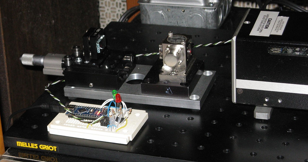
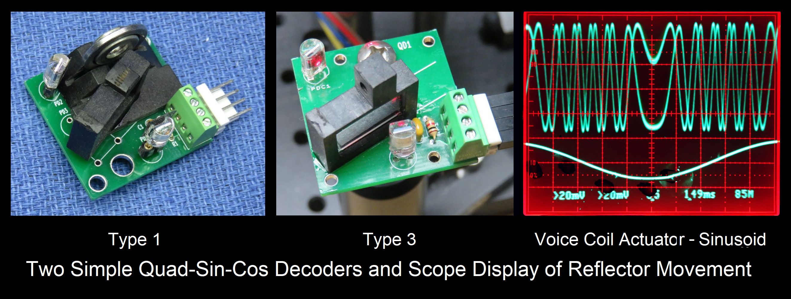
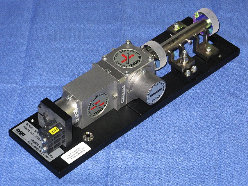
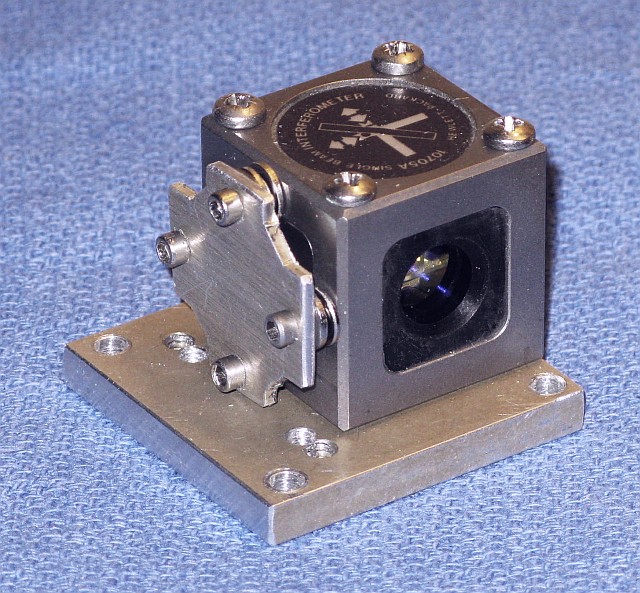
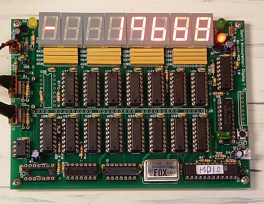
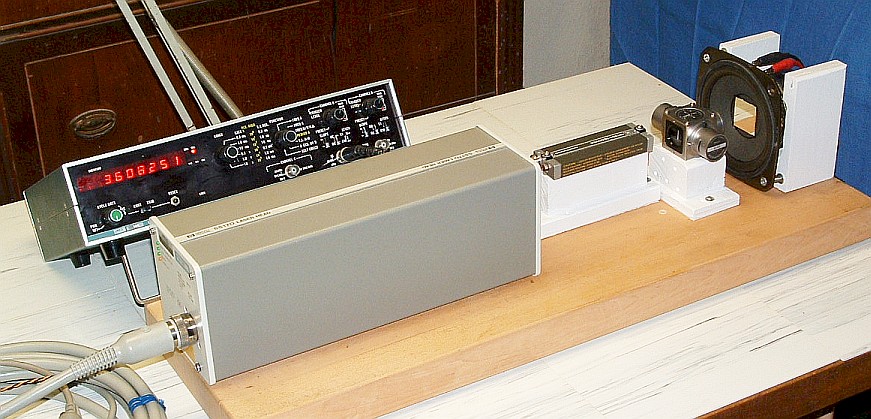
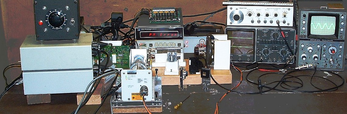
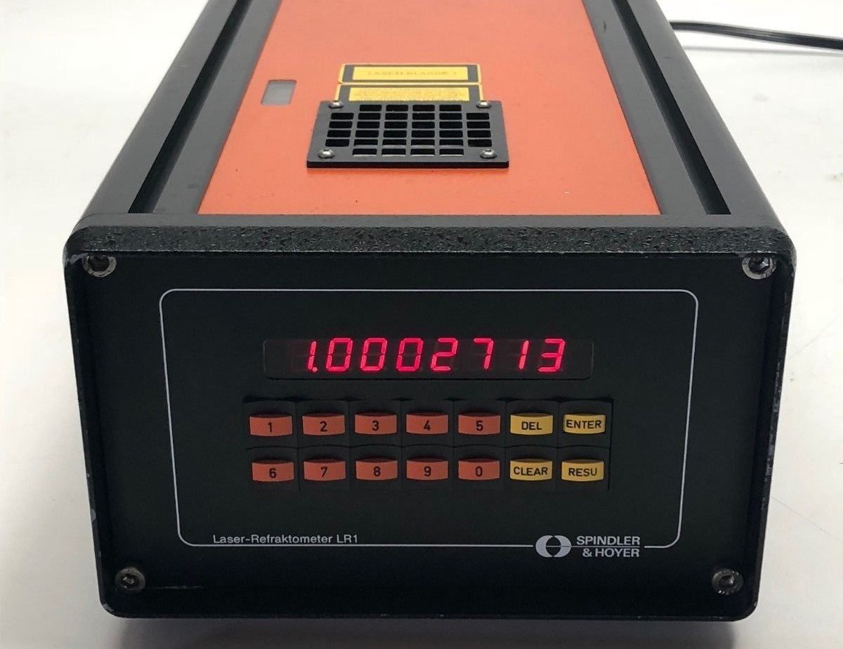
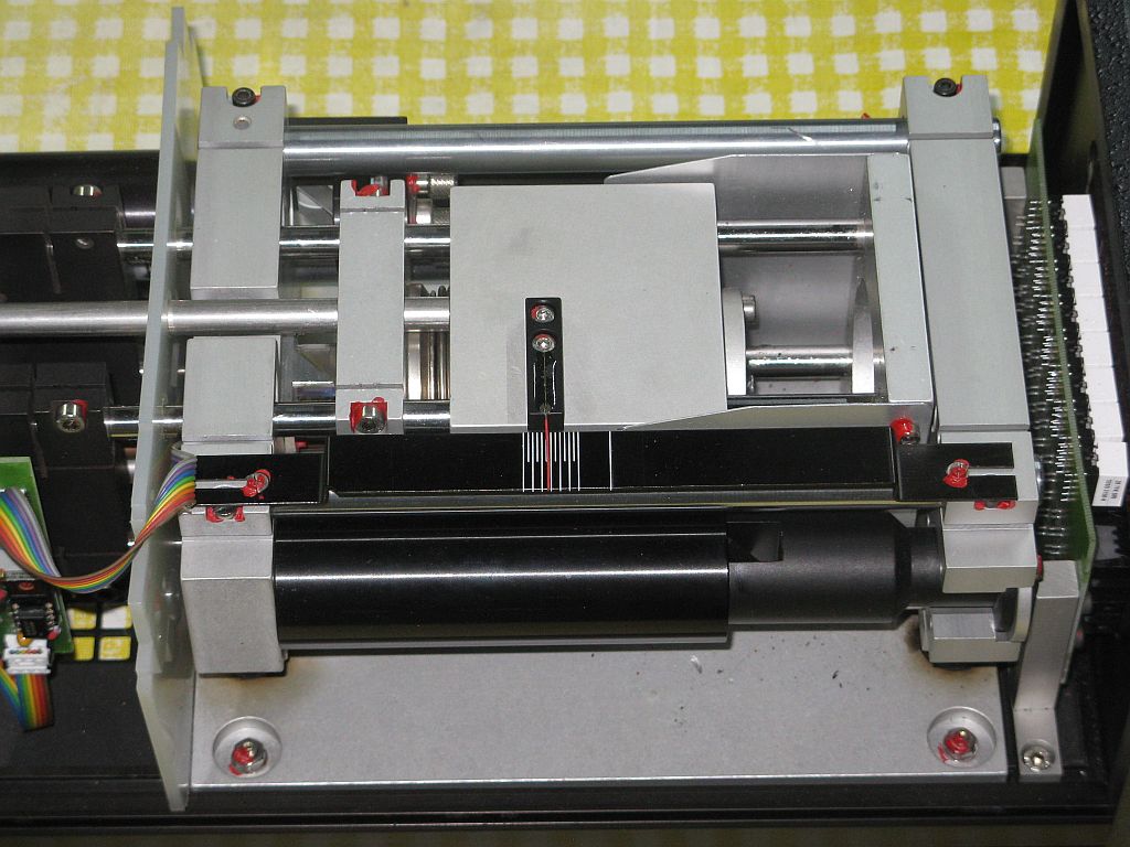
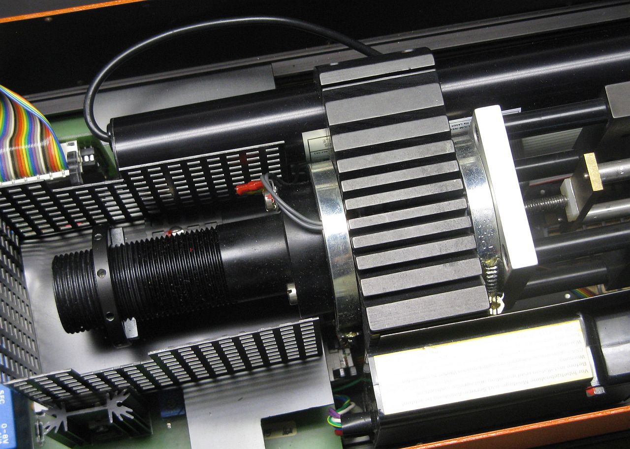
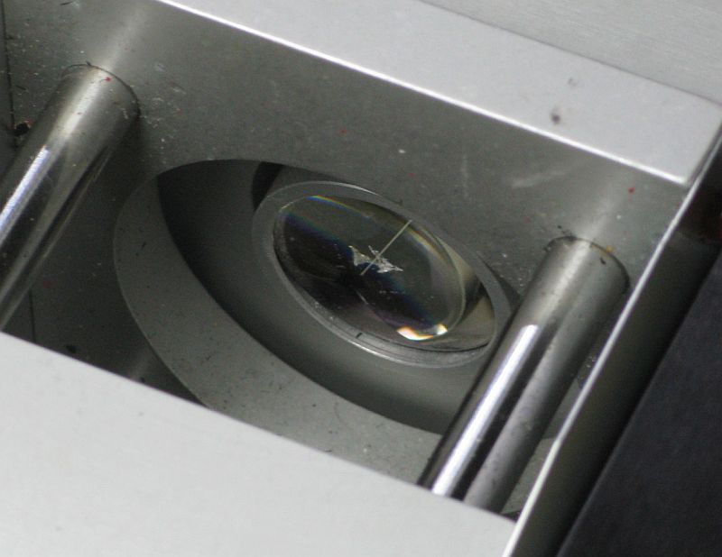
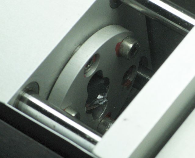
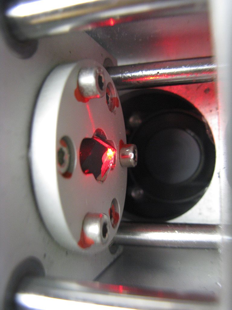
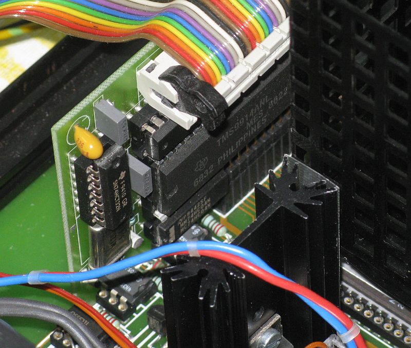
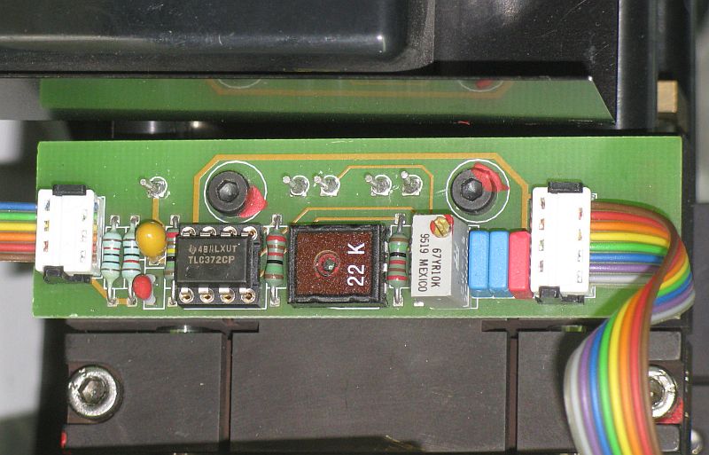
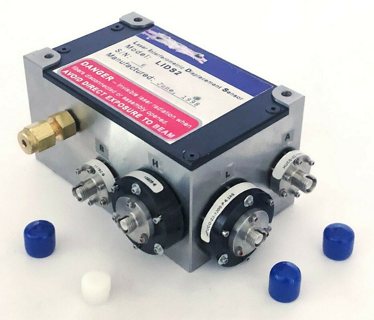
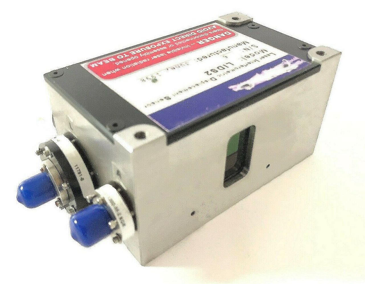
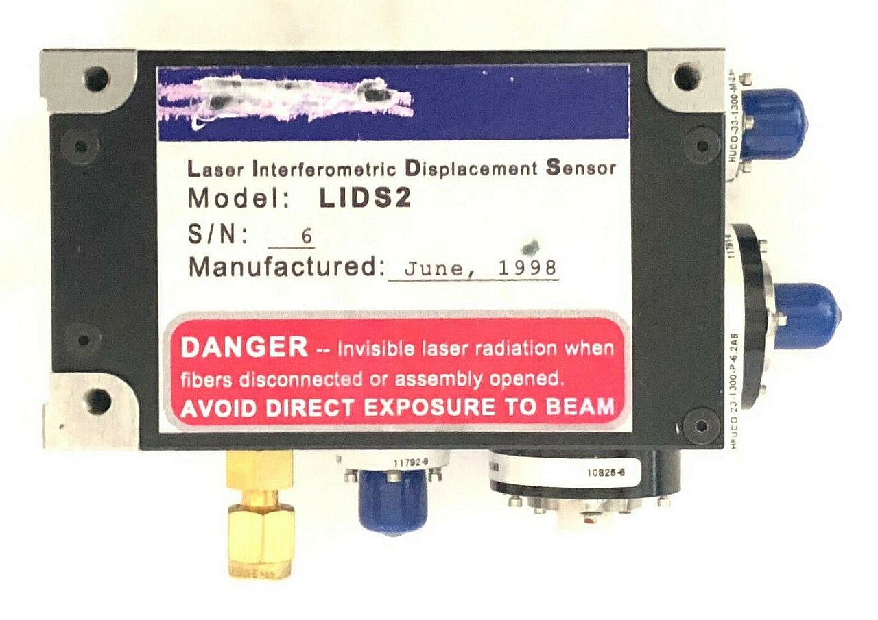
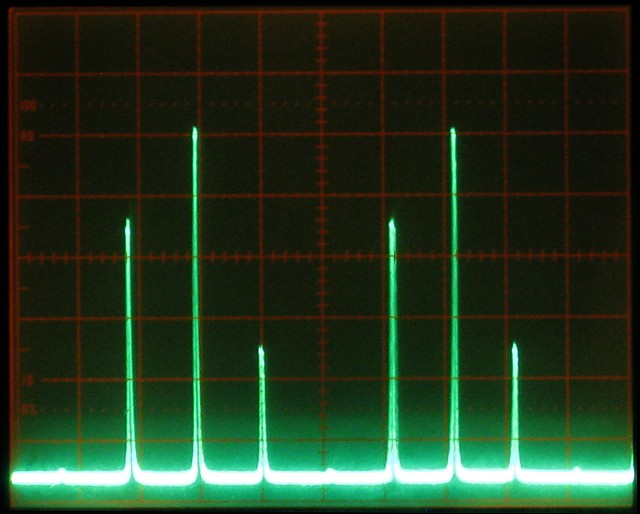
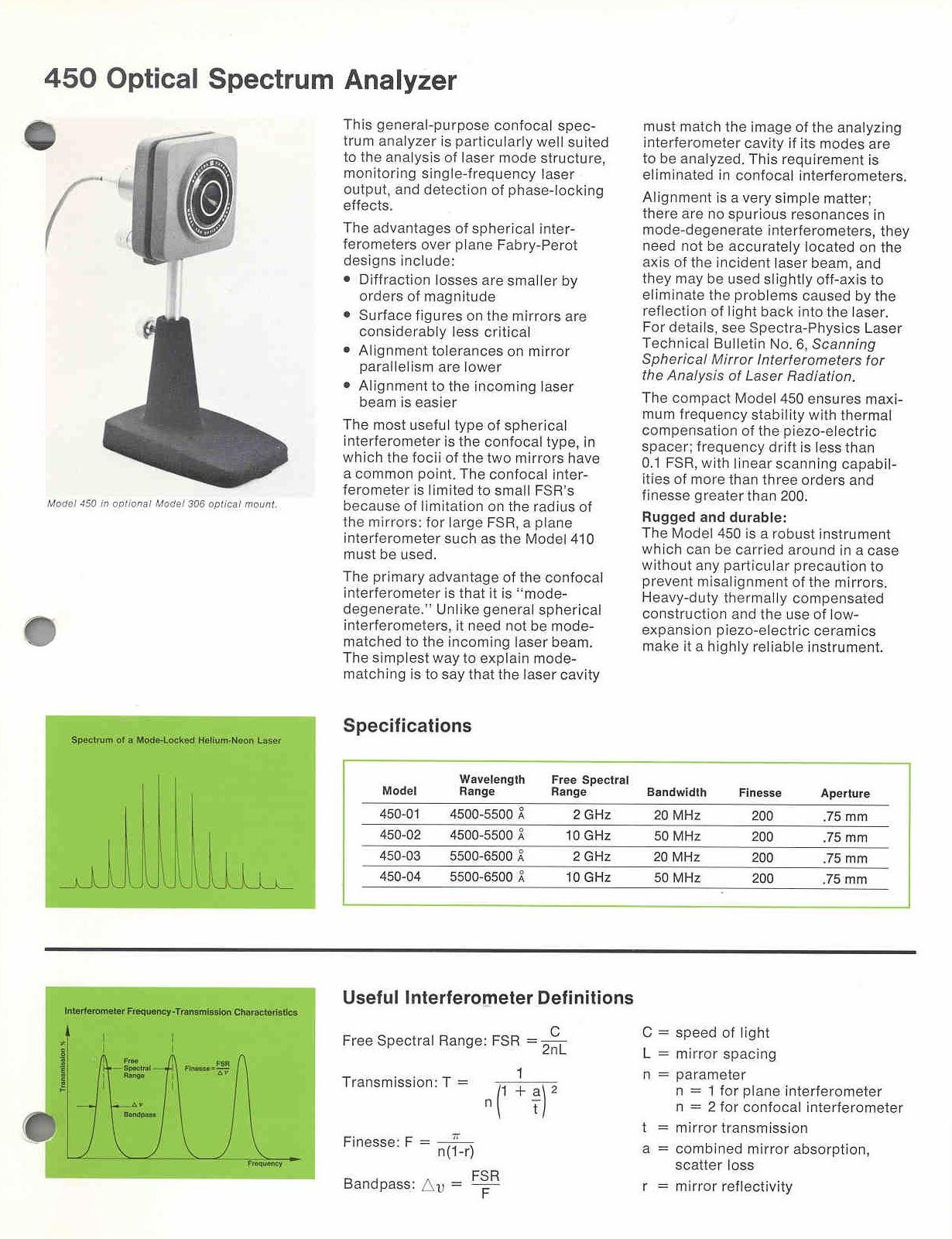
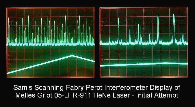
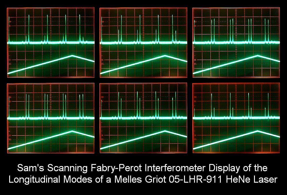
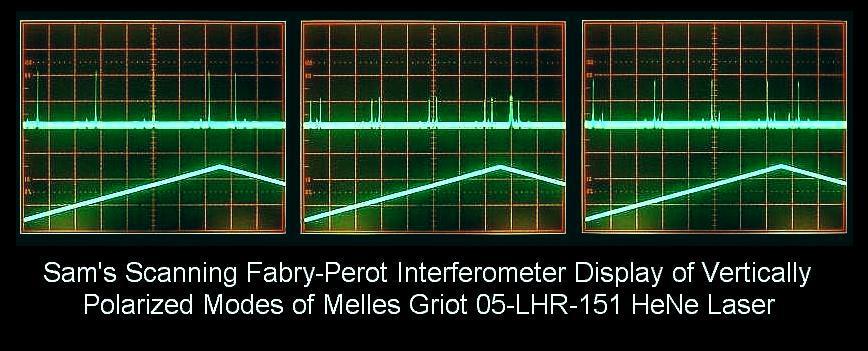
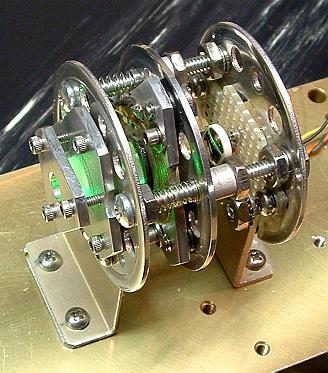
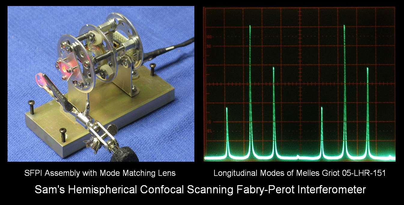
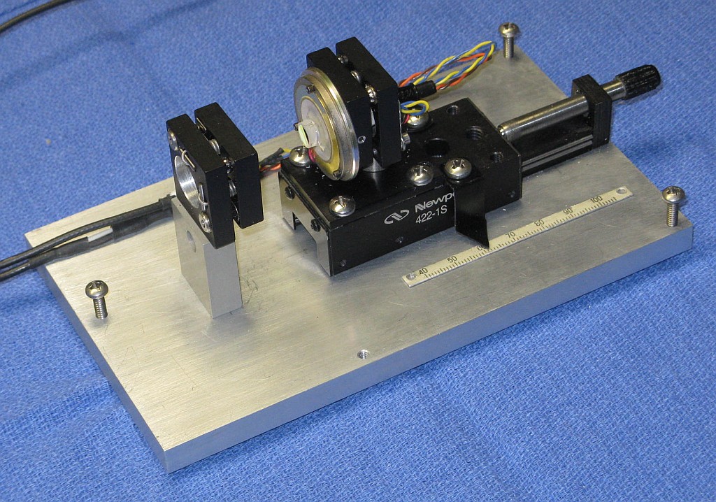
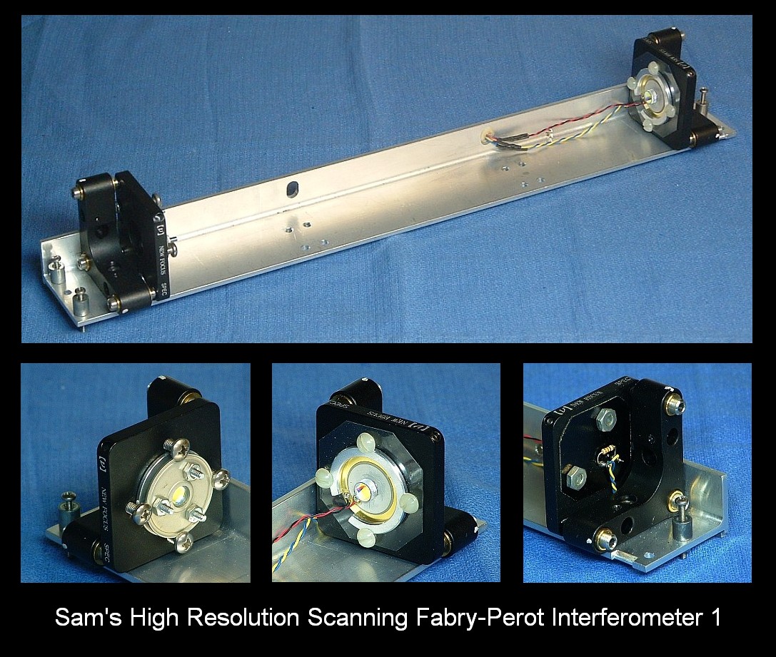
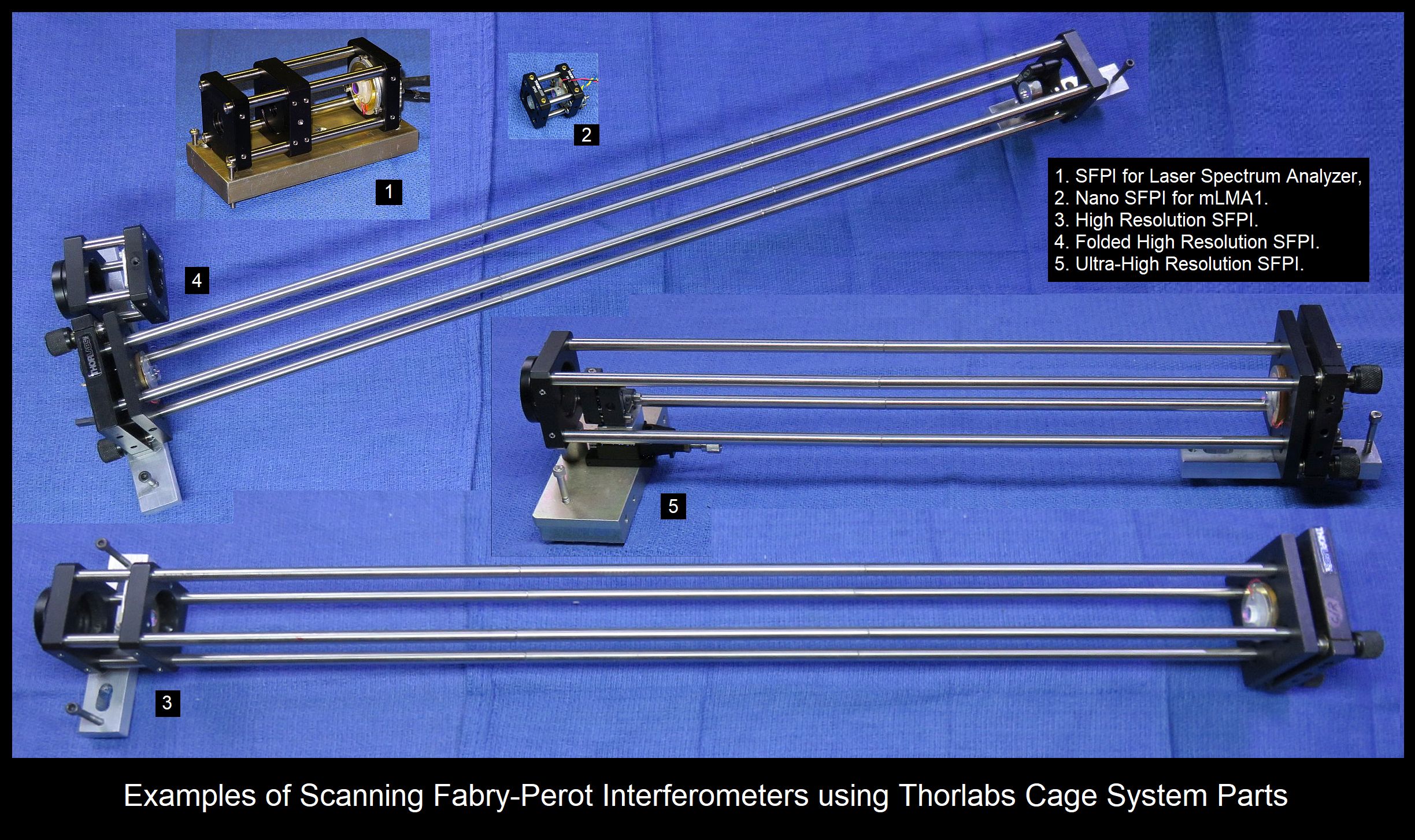
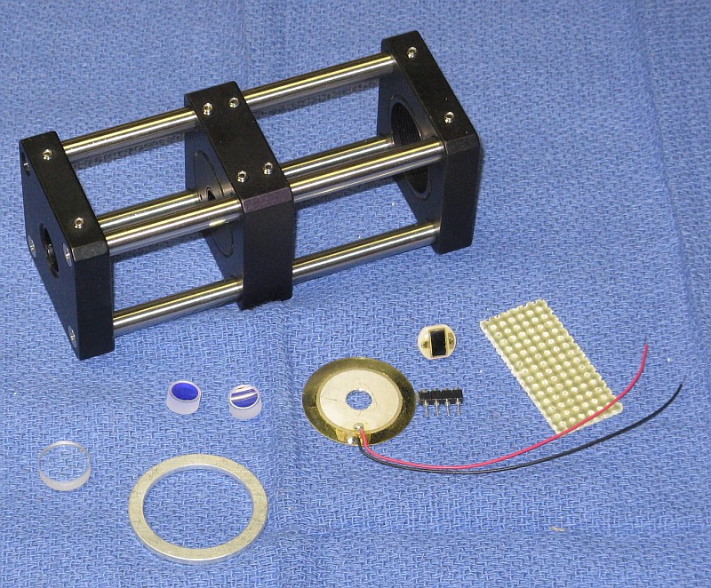
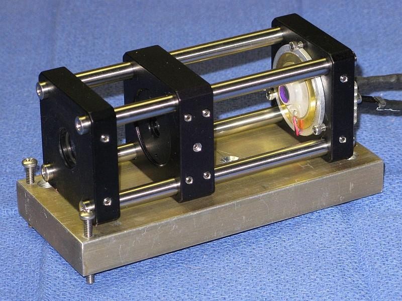
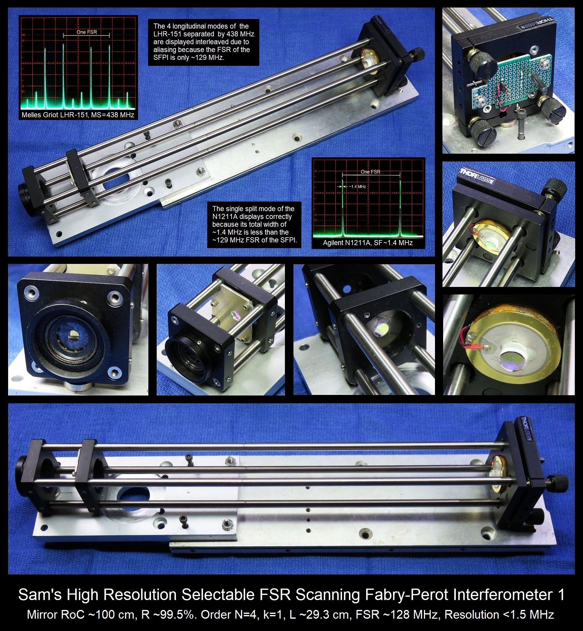
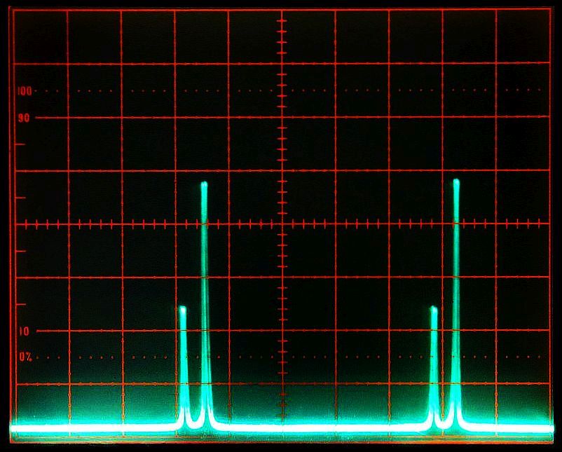
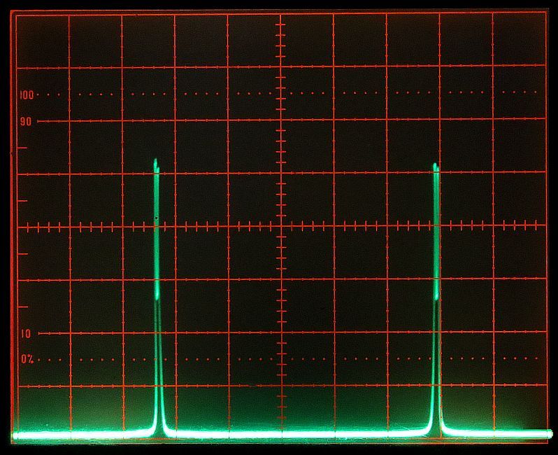
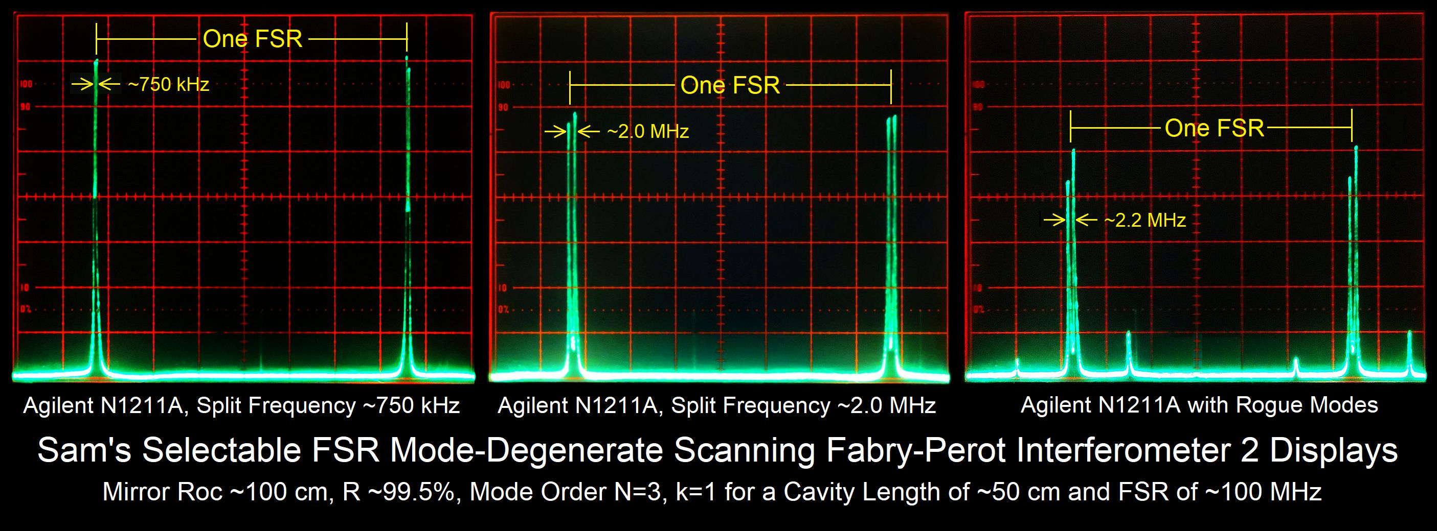
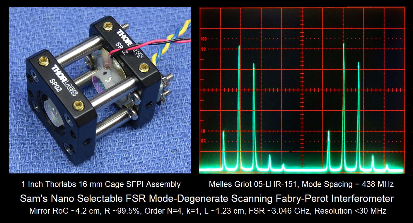
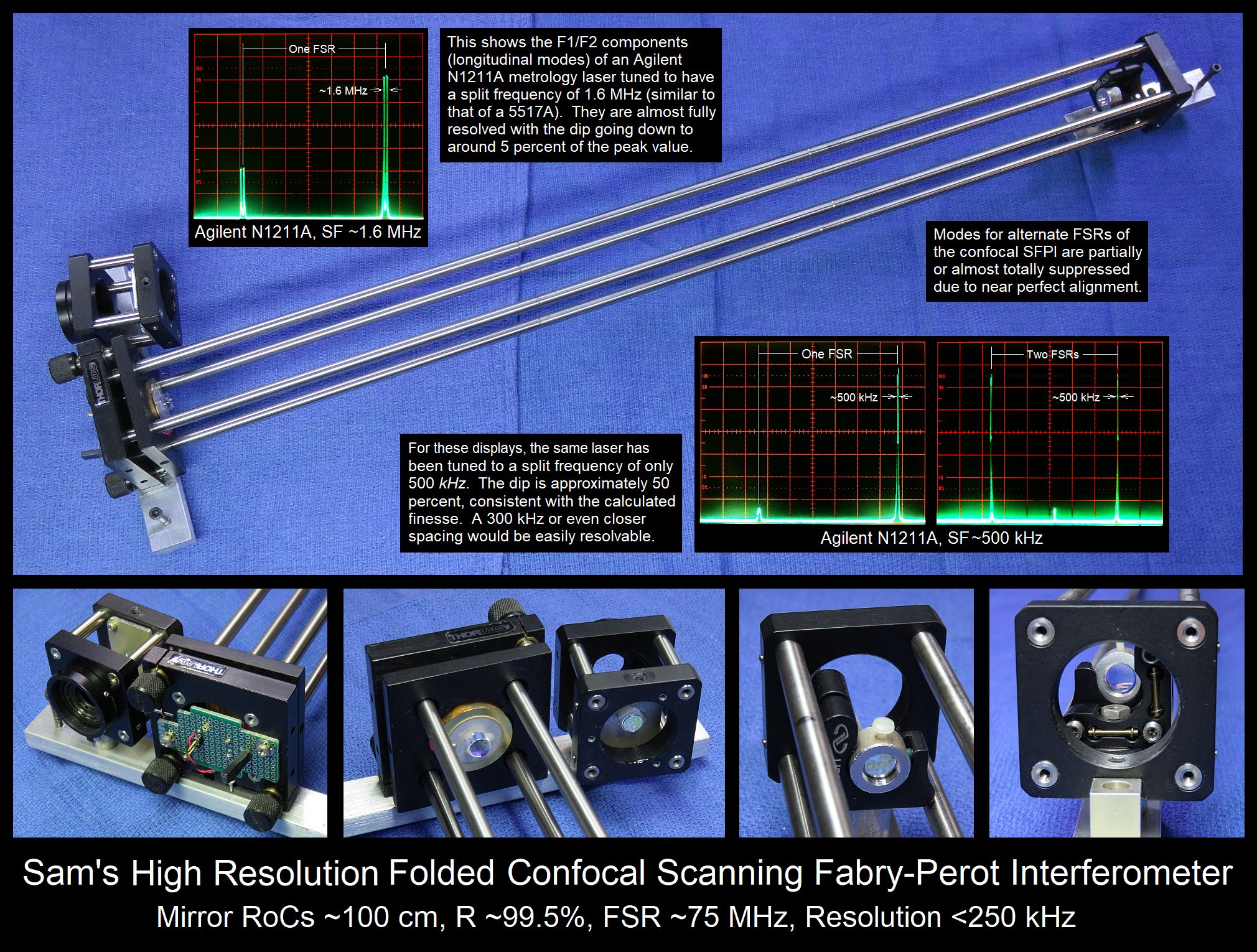
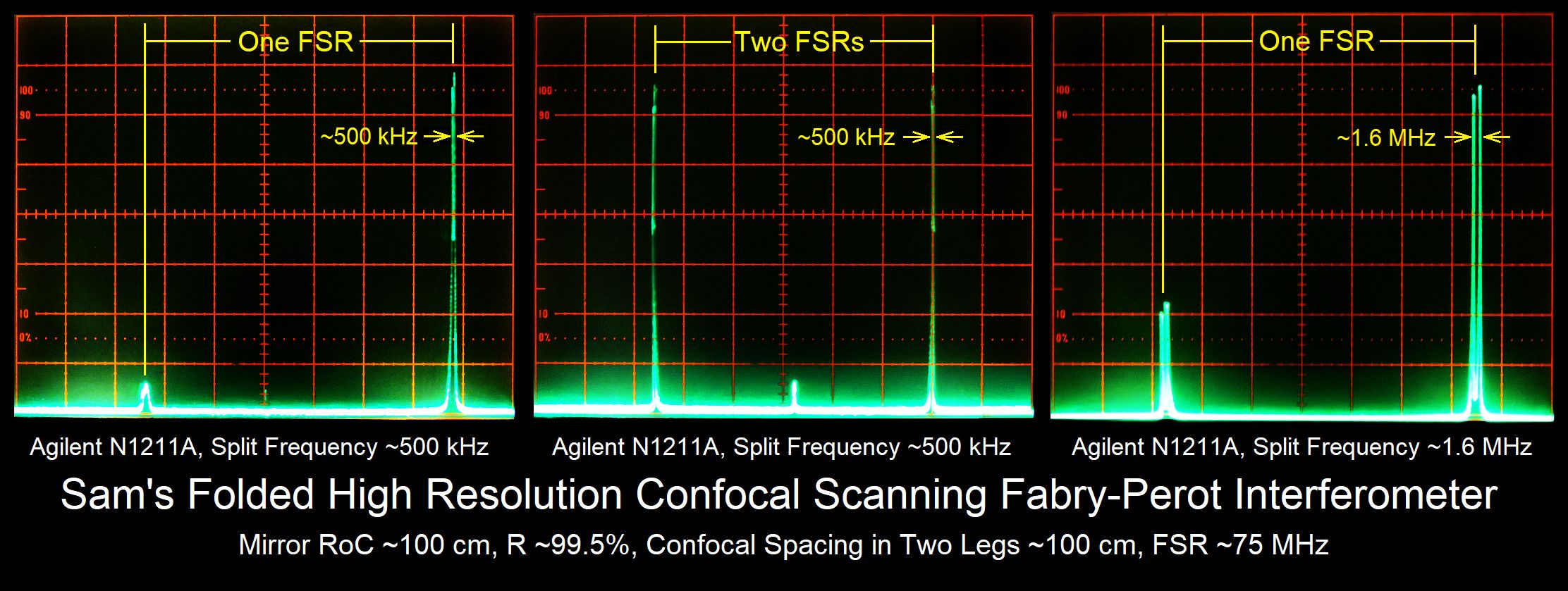
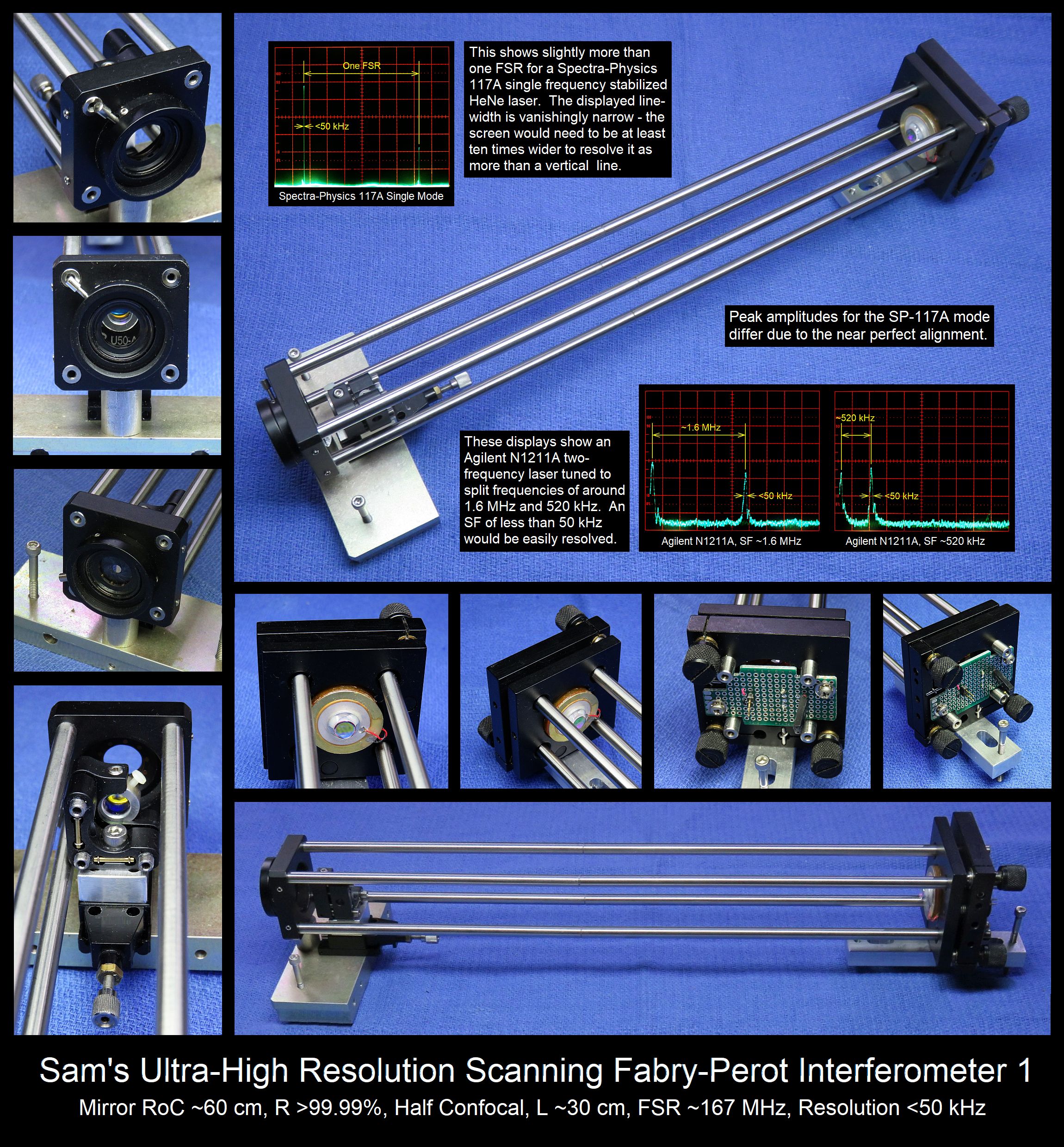
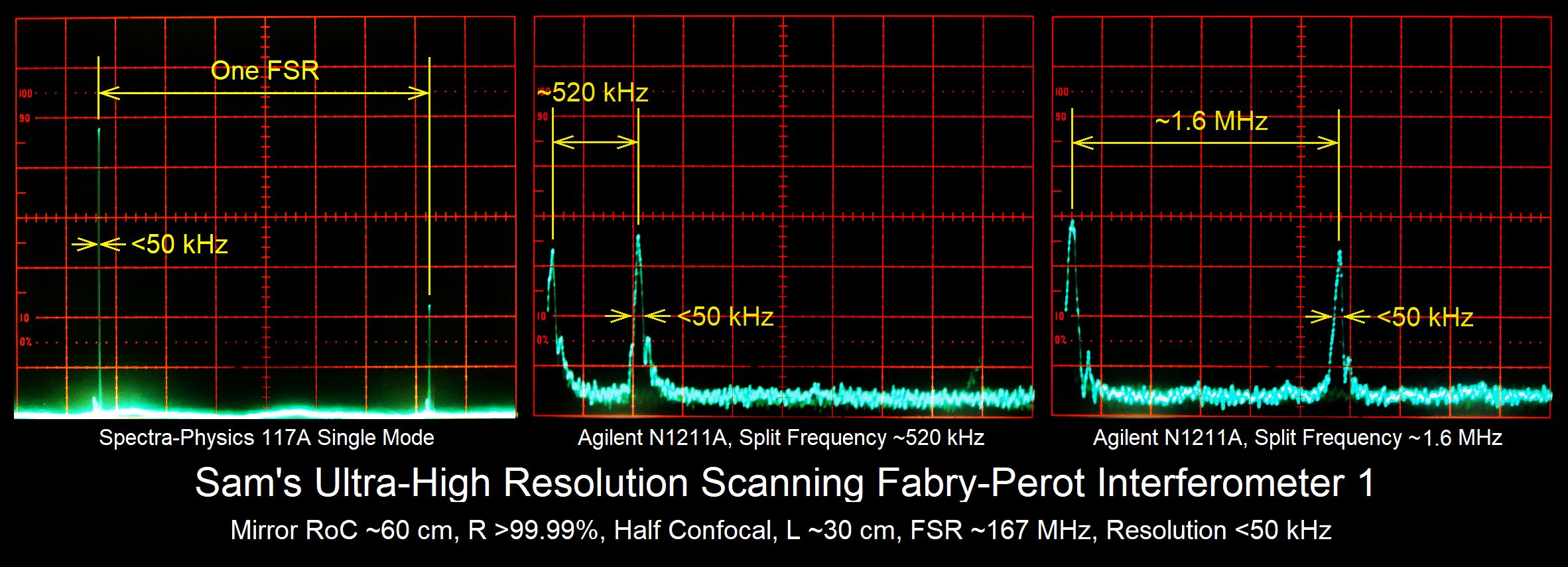
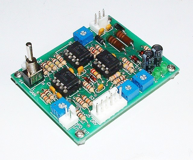
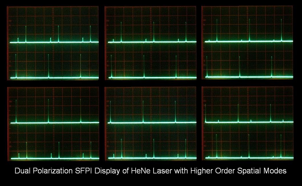
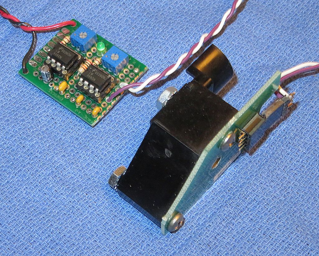
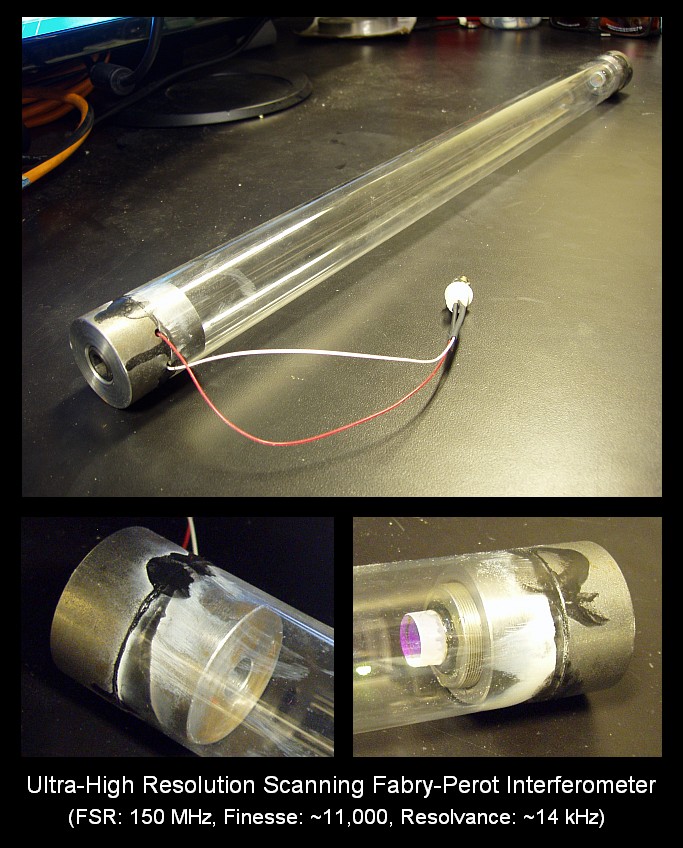
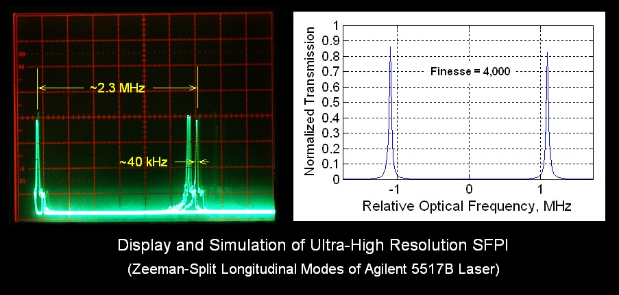
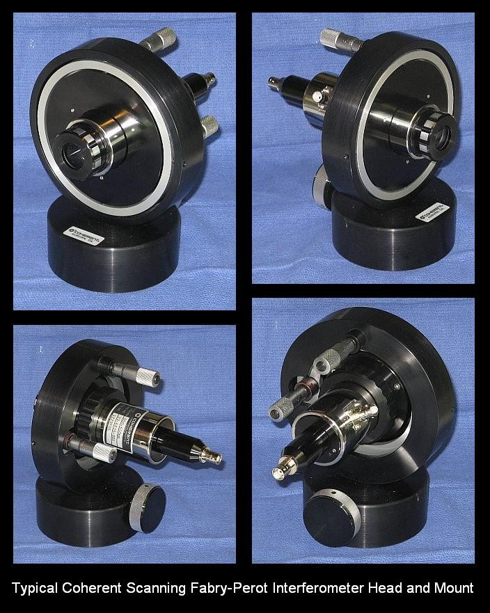
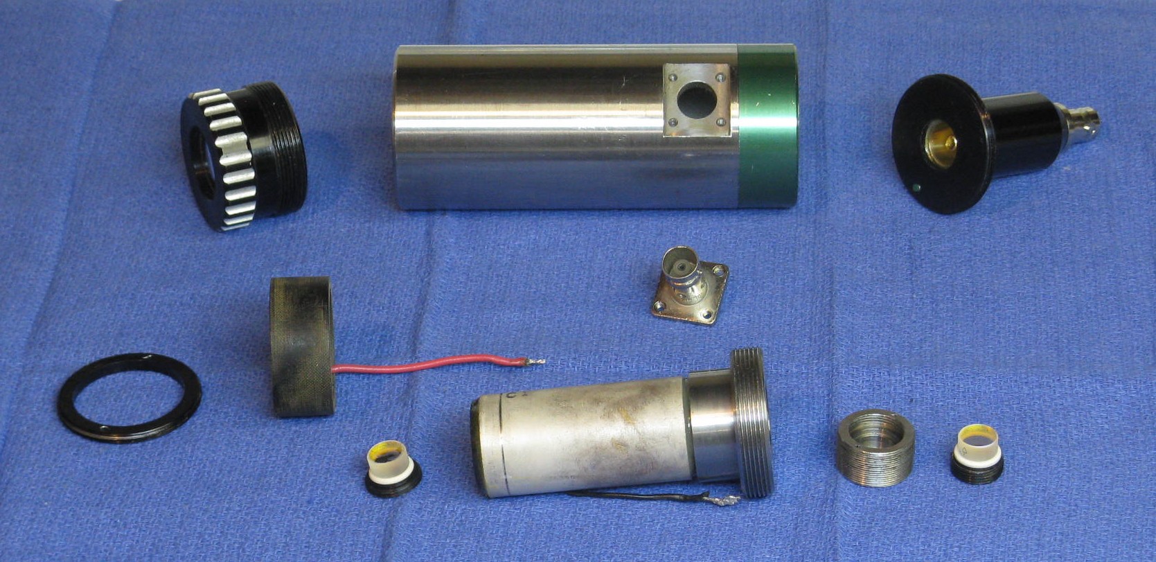
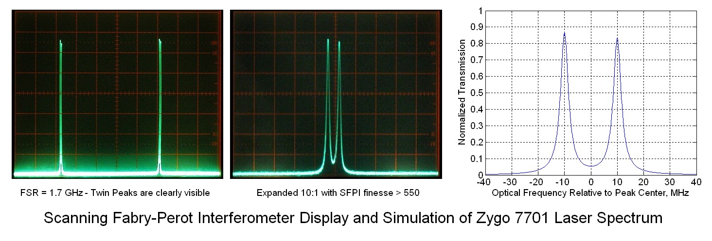
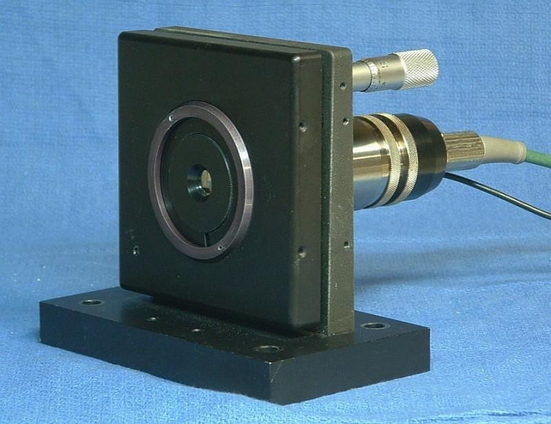
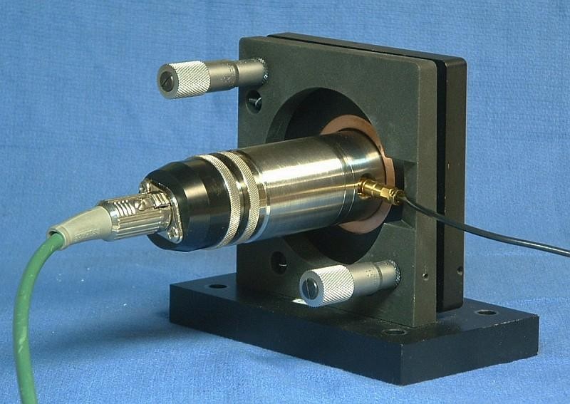
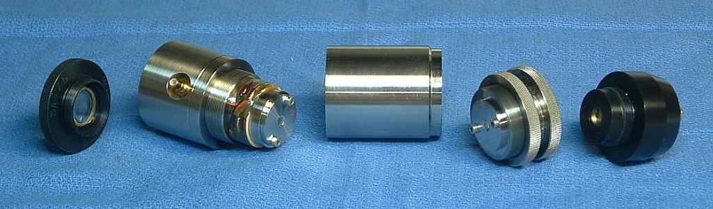
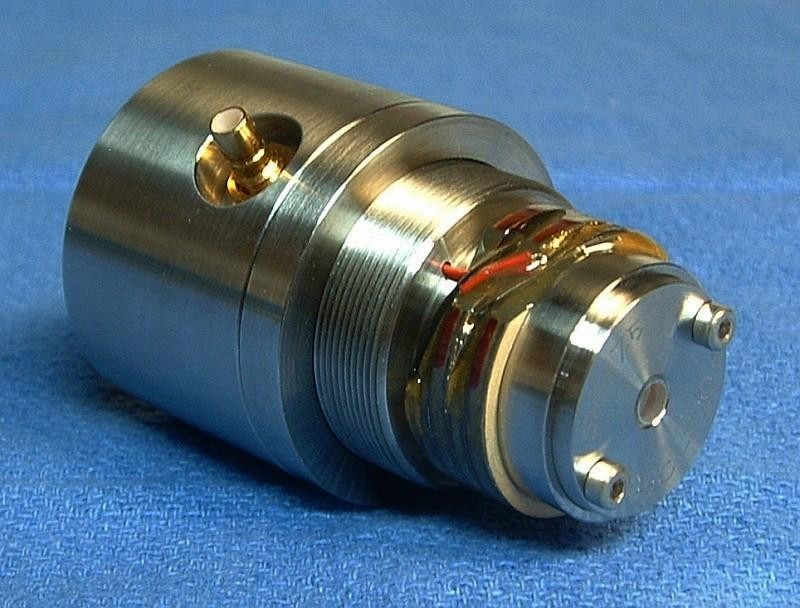
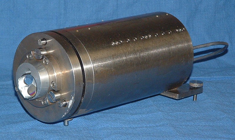
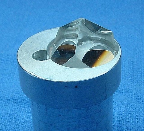
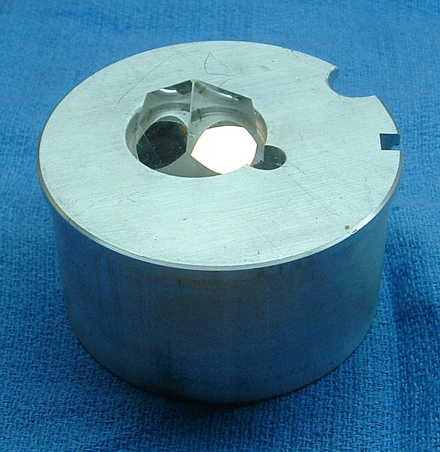
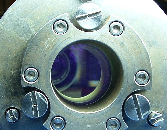
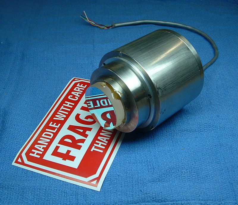
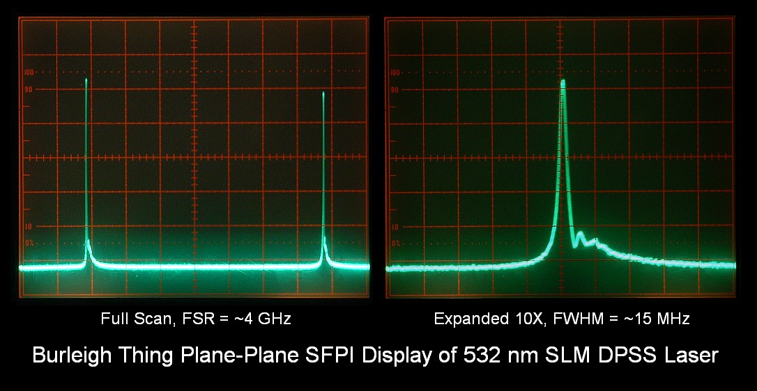
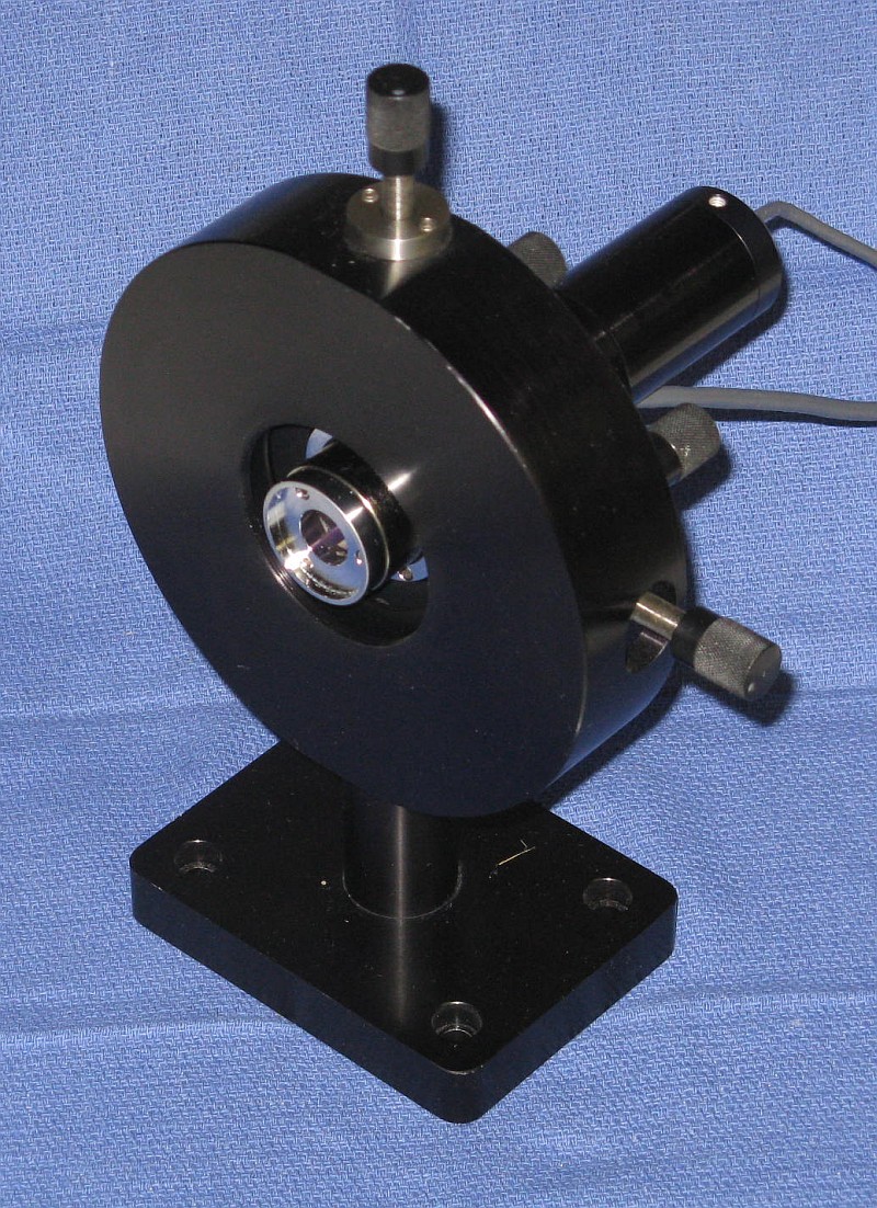
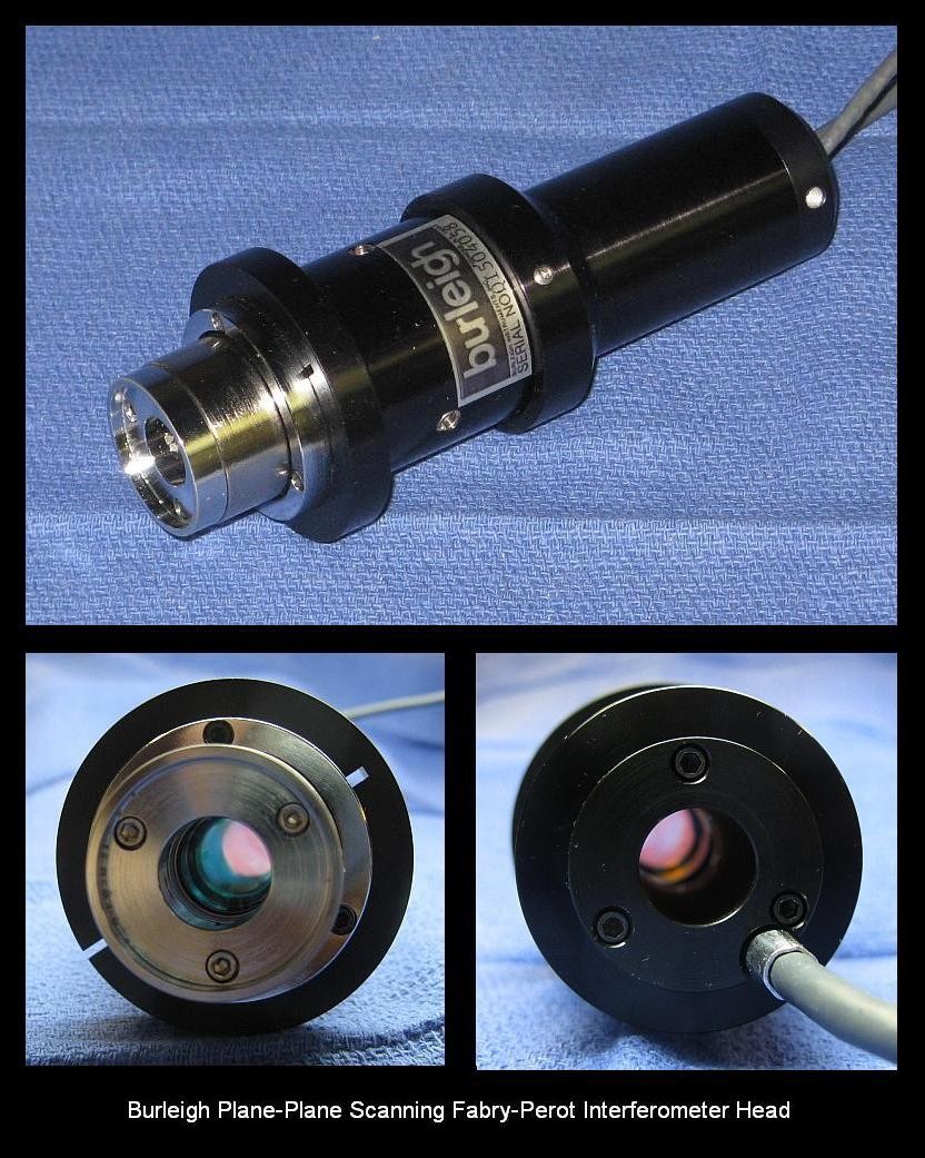
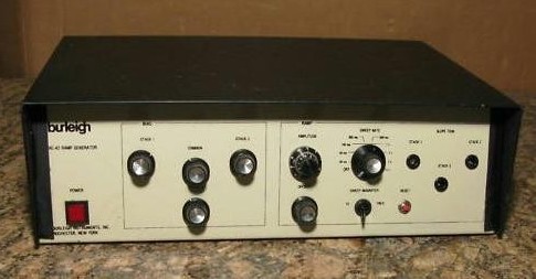
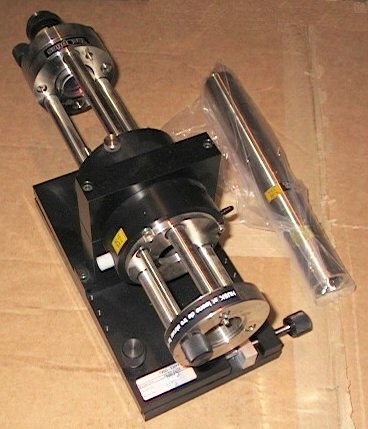
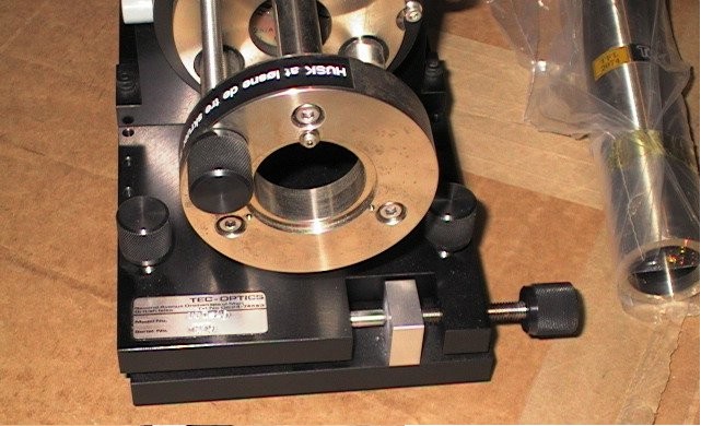
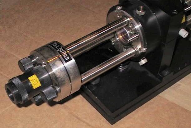
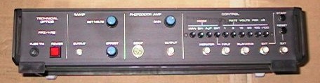
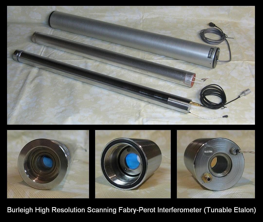
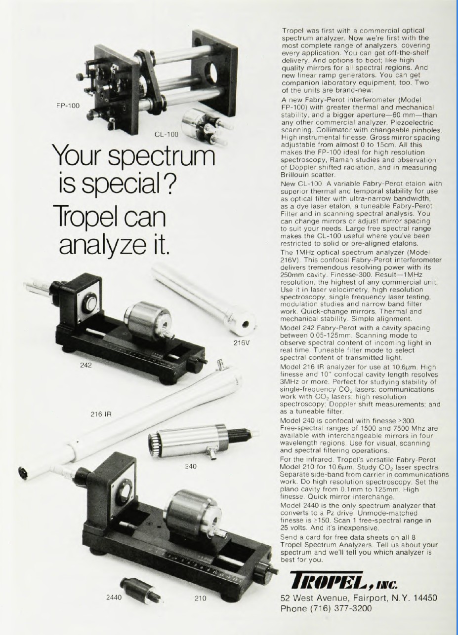
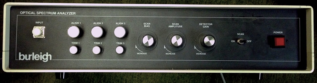
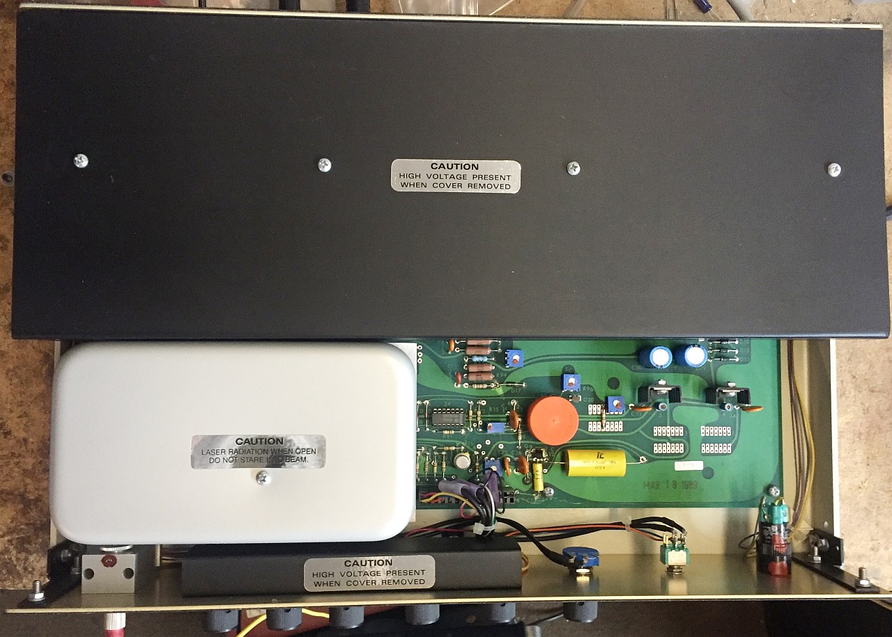
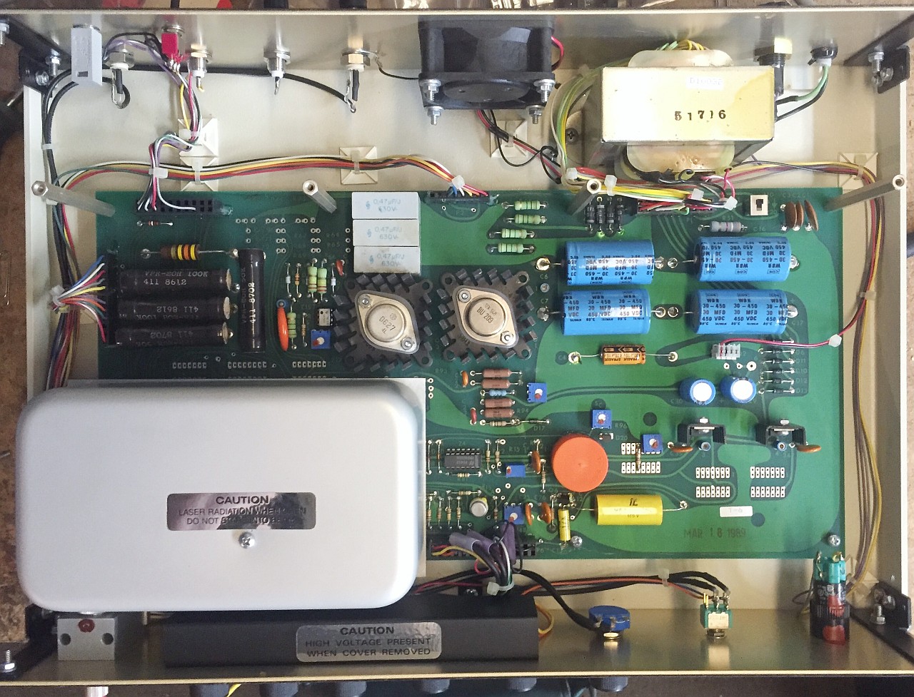
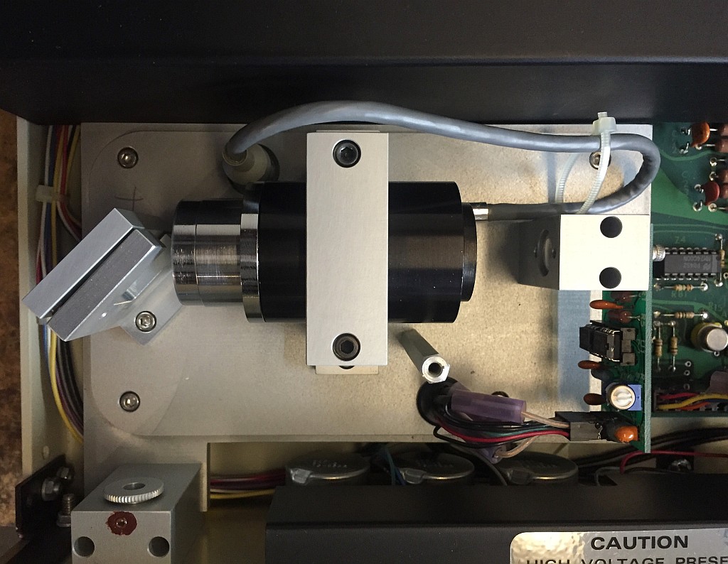
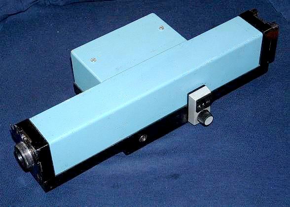
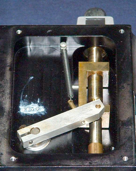
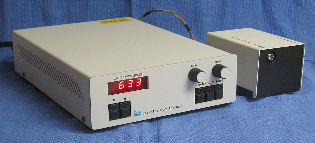
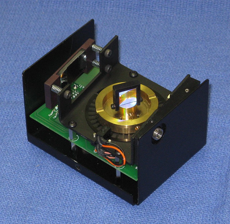
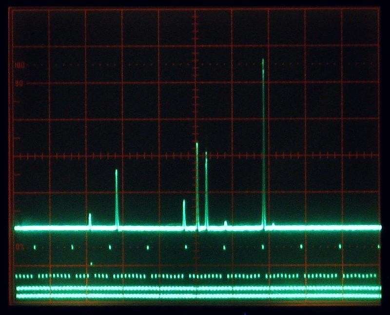
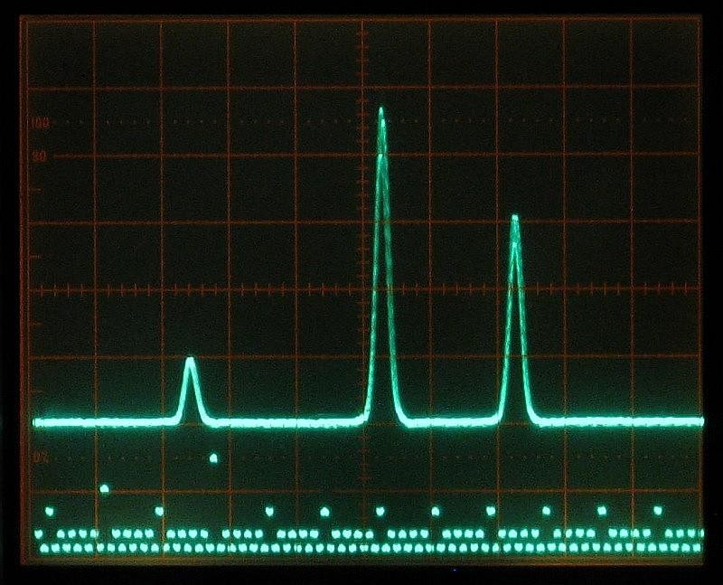
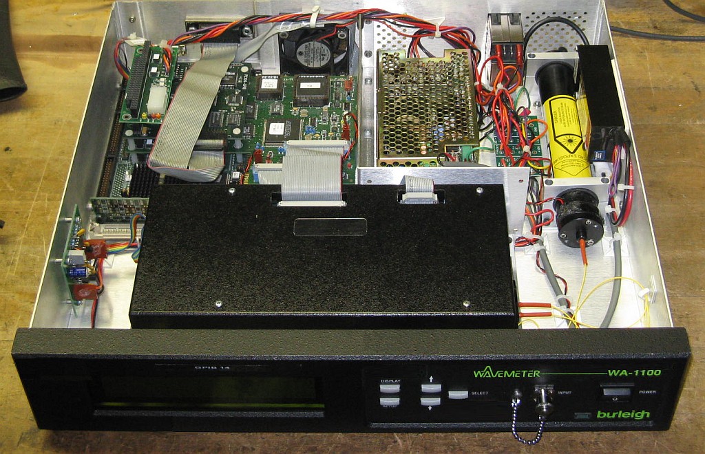
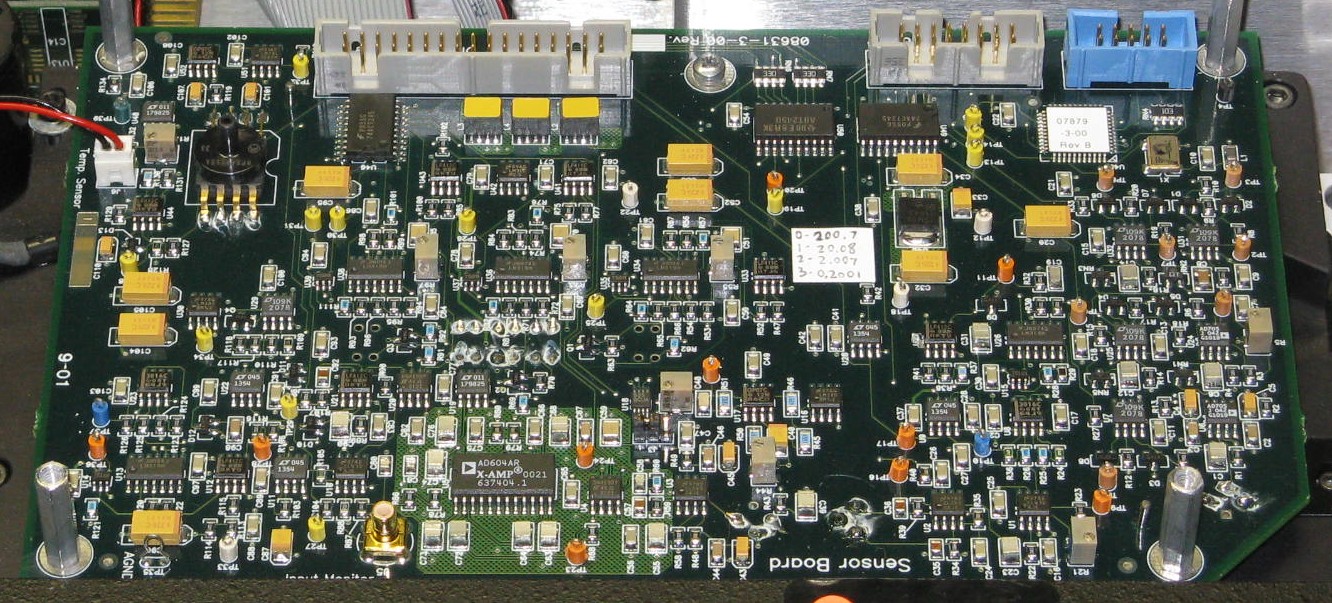
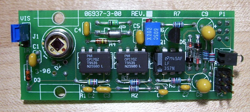
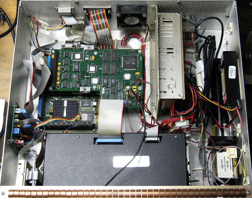
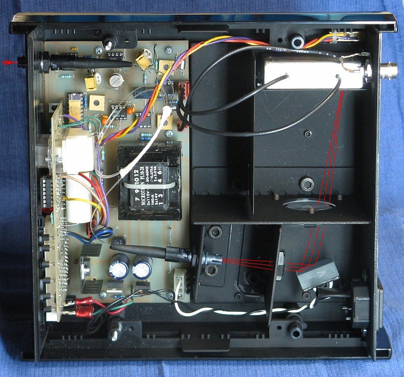
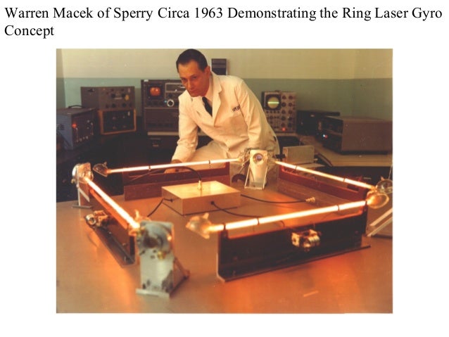
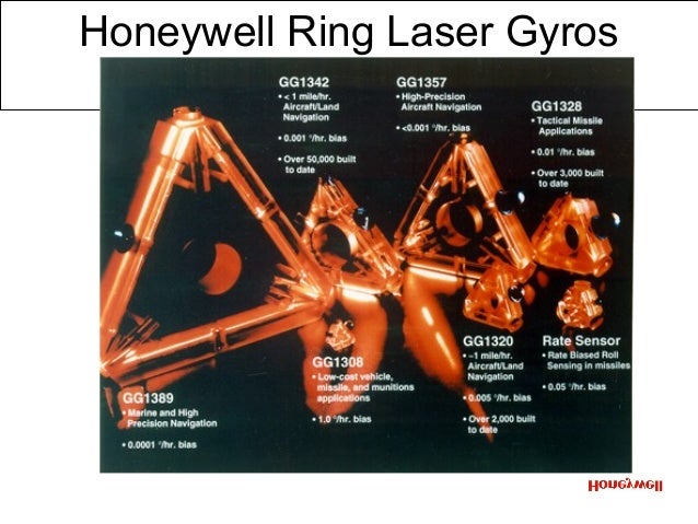
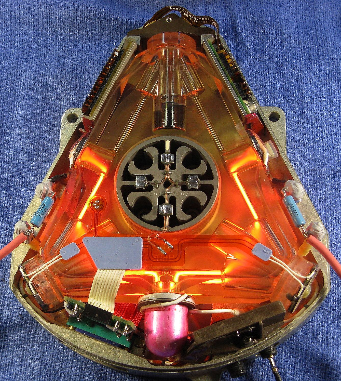
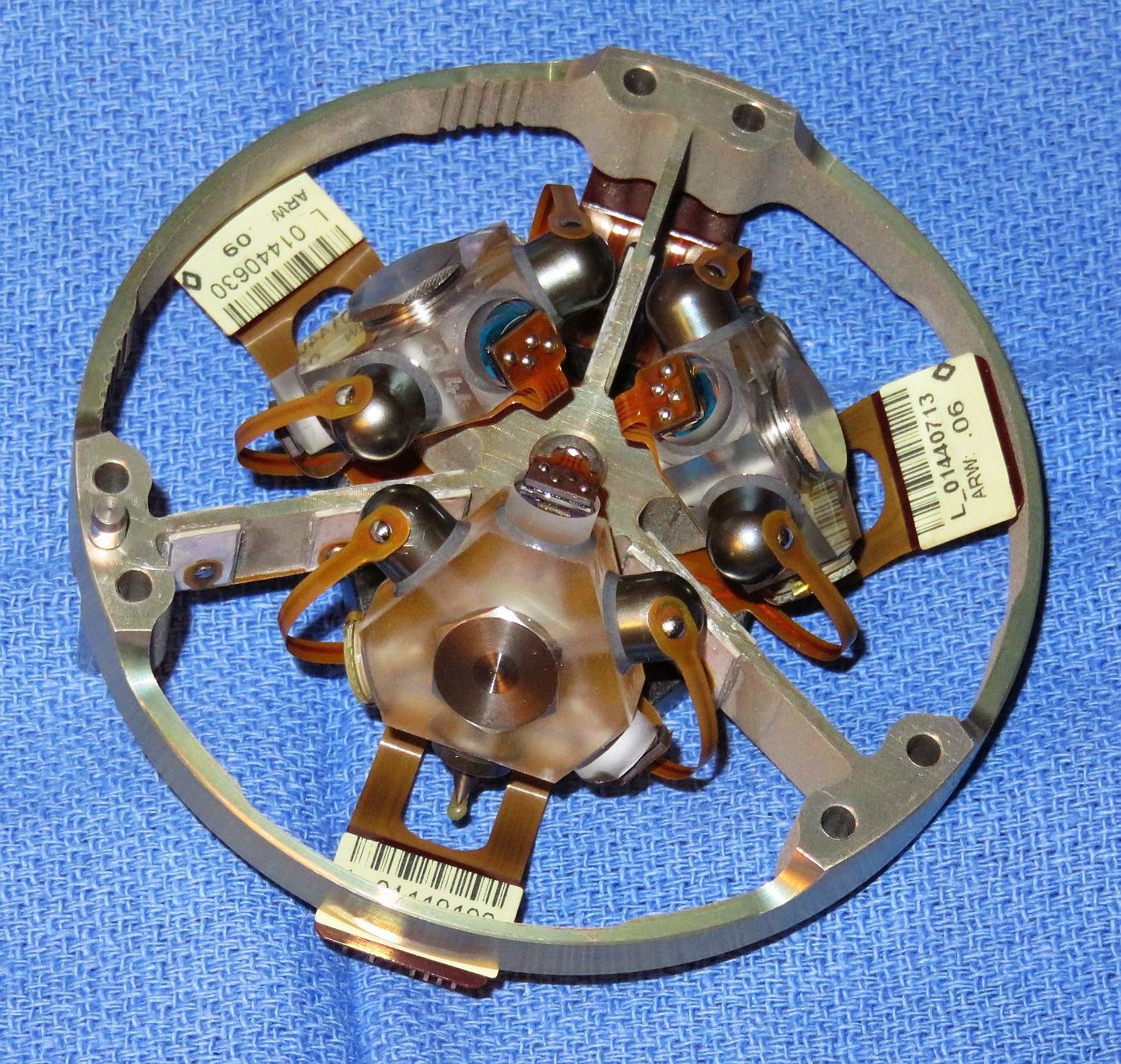
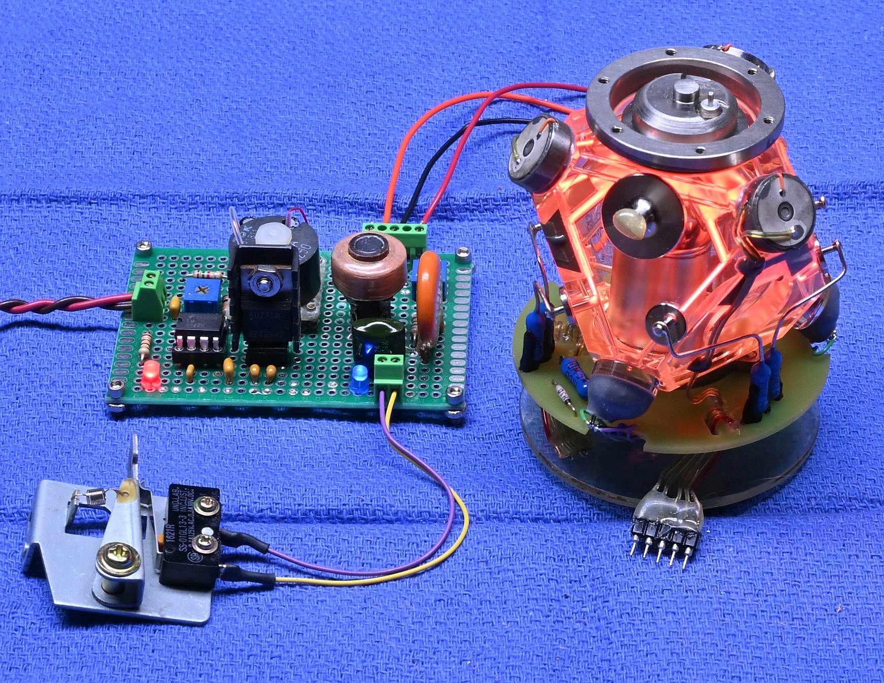
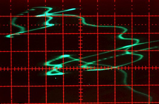
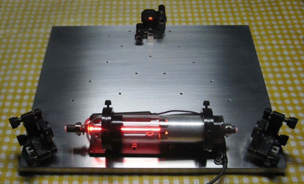
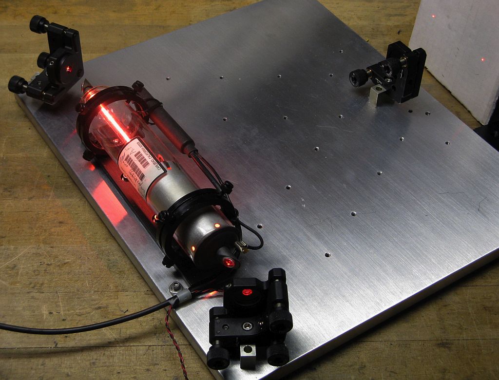
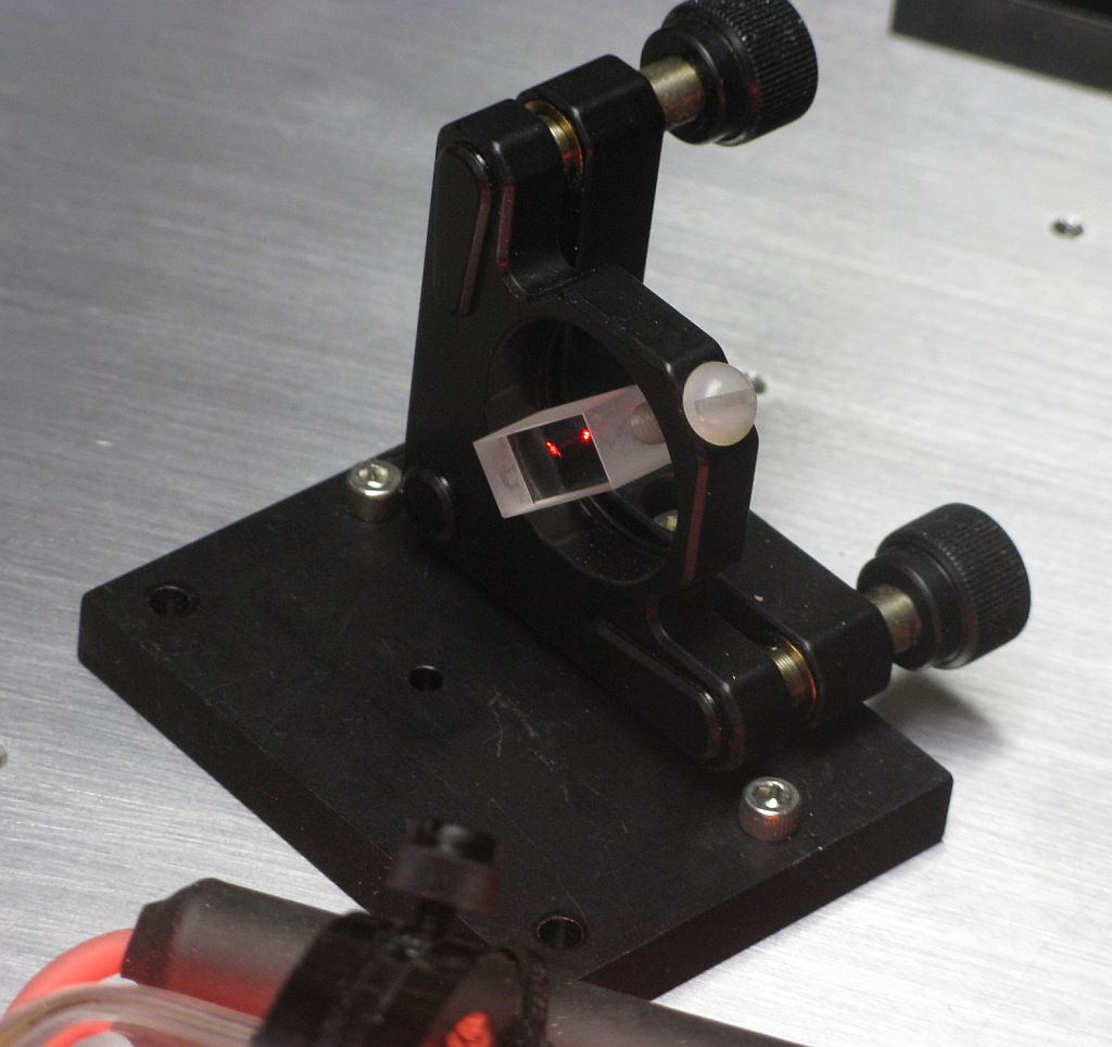
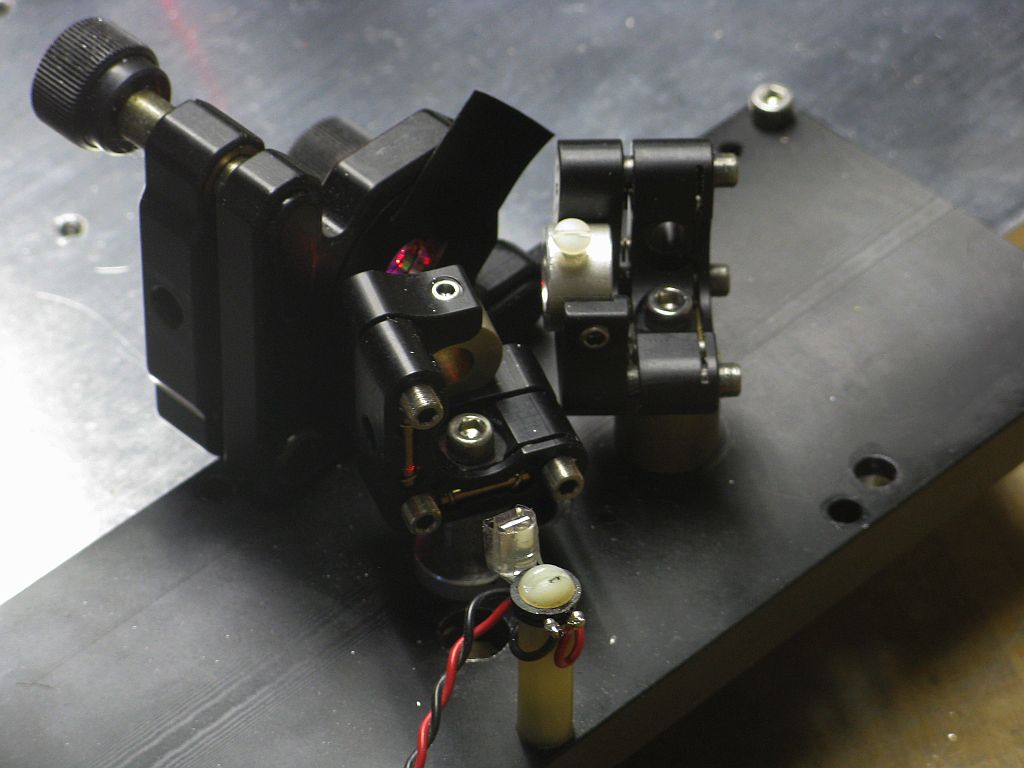
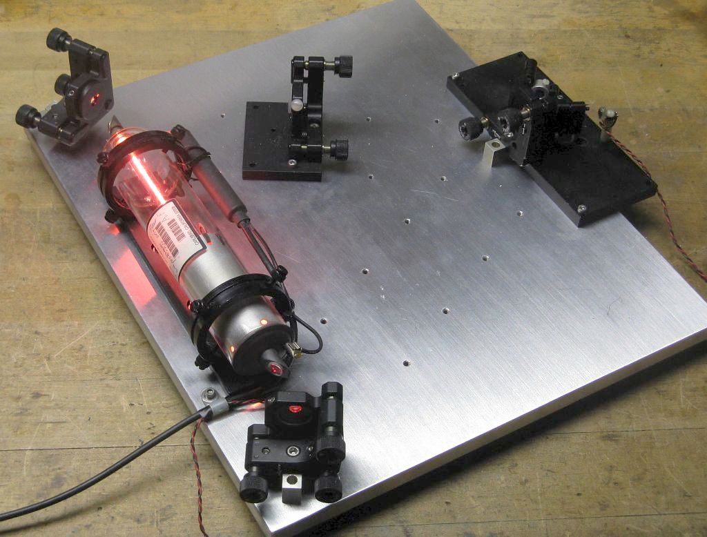
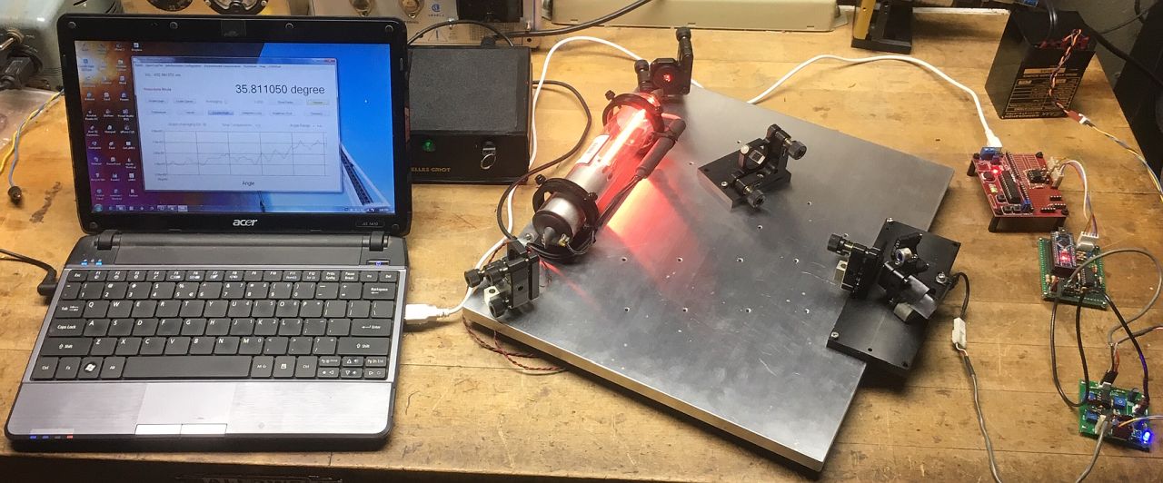
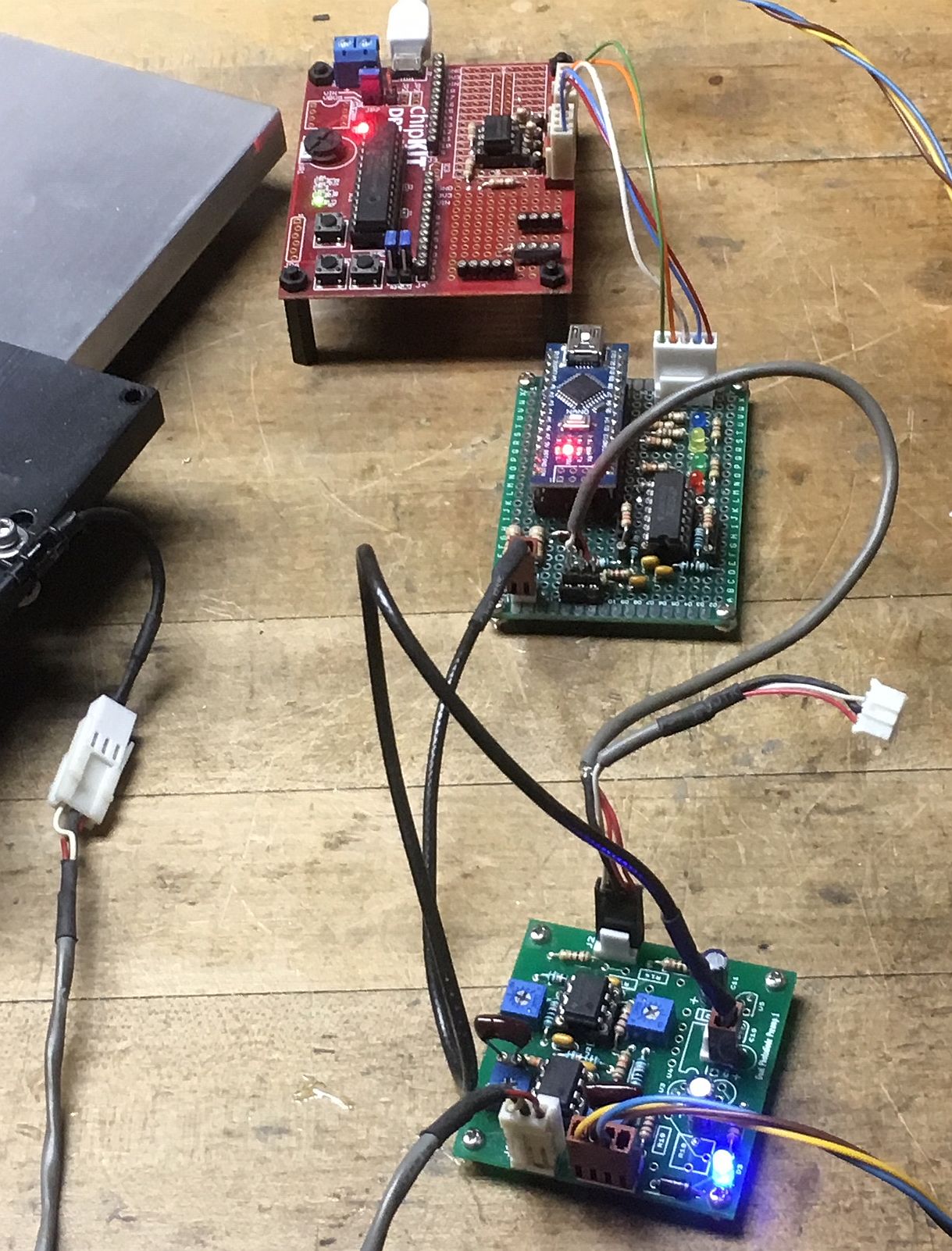
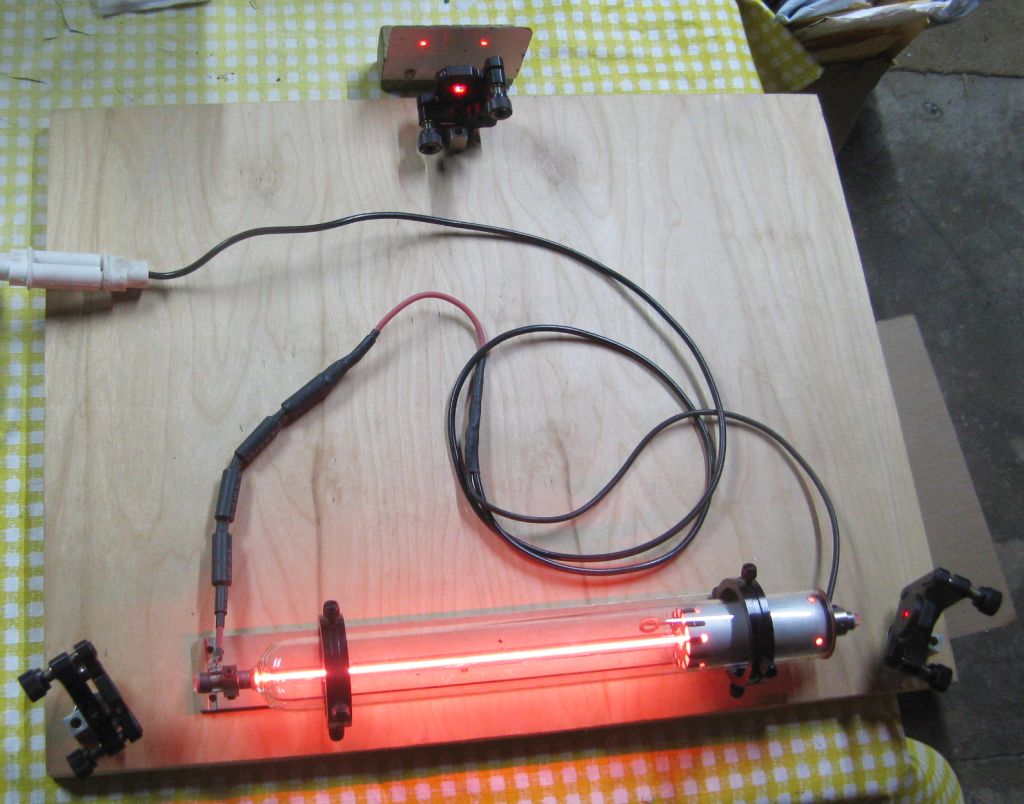
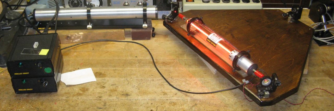
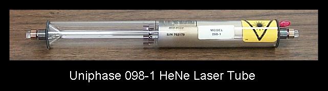
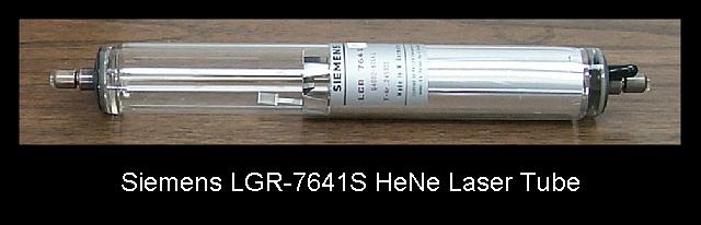
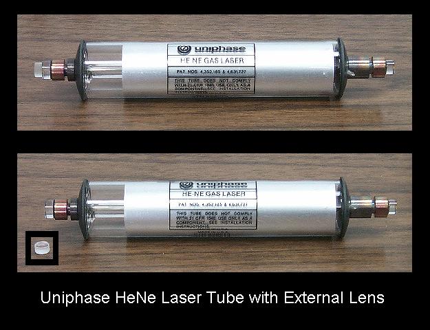
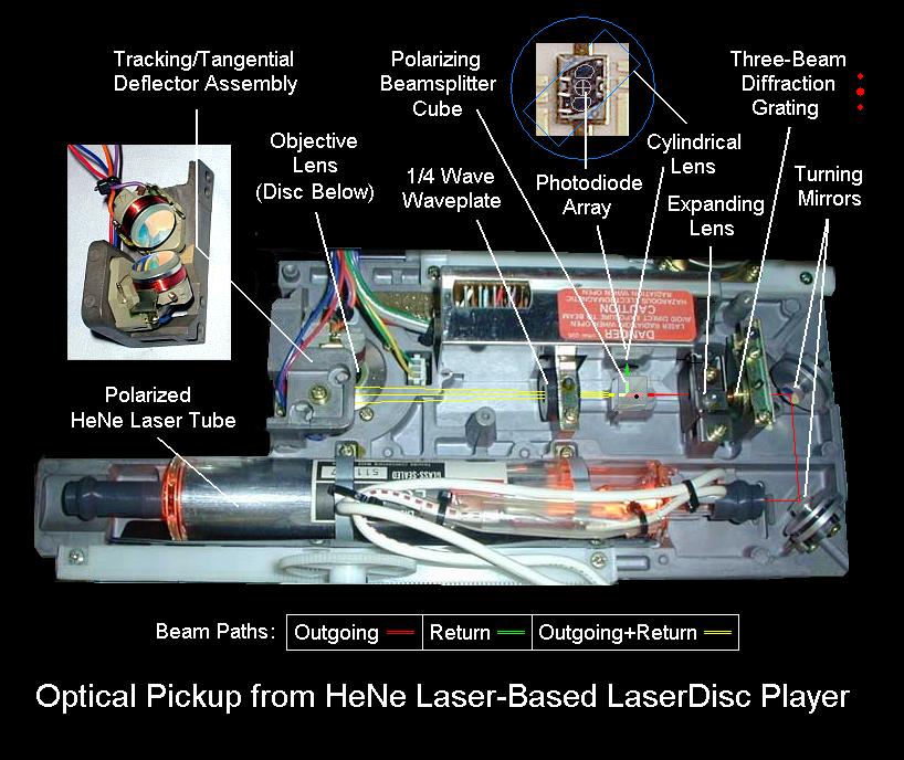
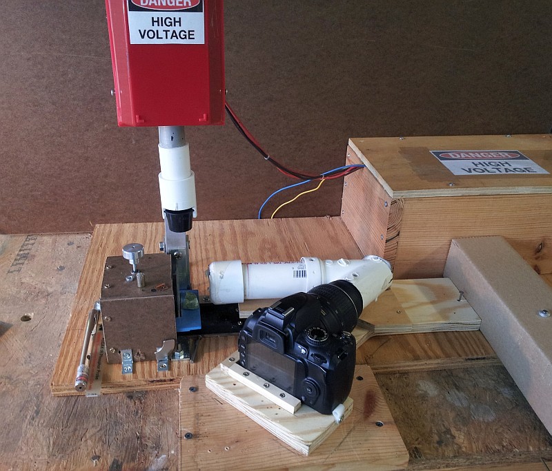
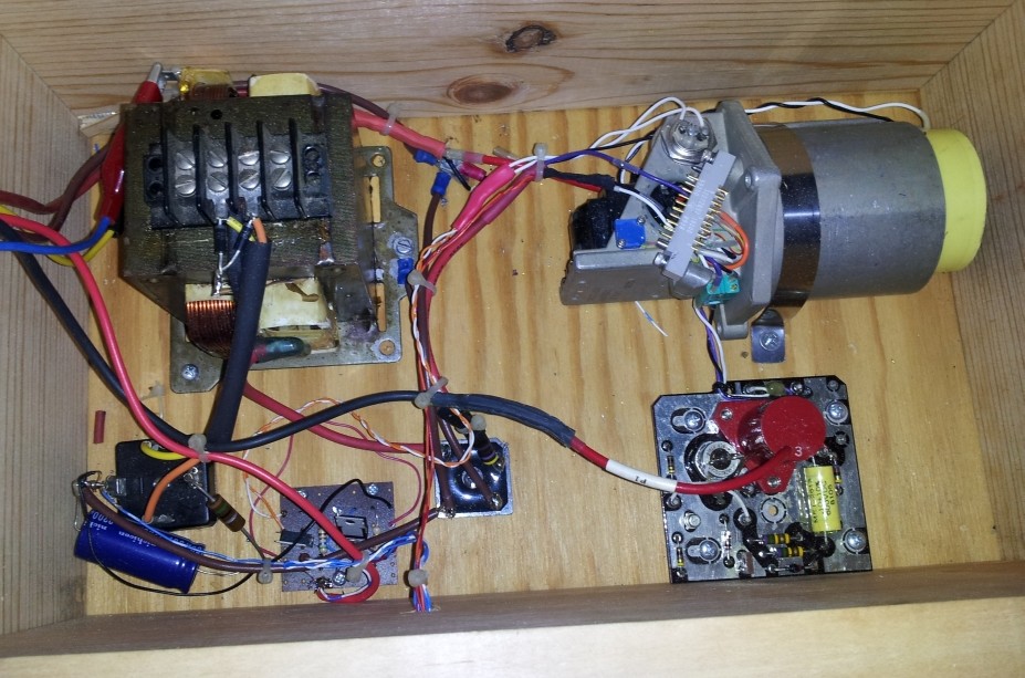