Considering the enormous gap between your likely capabilities and those of a large corporation, the final result probably won't match a commercial laser in either performance or appearance (though there are a few exceptions). However, that shouldn't be the point of the exercise. Rather, a laser (or multiple lasers after you are hooked) should be built for the education, challenge, and opportunity for experimentation afforded by dealing with all aspects of laser construction. And, the realization that the laser you built is a complex precision device you were able to bring to fruition successfully.
To the amateur scientist, experimenter, hobbyist, or even weekend tinkerer, there is something about the idea of actually creating a working laser that makes its construction from the ground up a very attractive and rewarding project with "first light" - the instant that your home-built laser first emits a coherent beam - approaching the excitement of a religious or sexual experience!
Although the laser is a device or instrument based on fundamental quantum mechanics which is very simple in principle - an excited medium between mirrors - building one successfully may require mastering several disciplines not normally found in even the high tech home. These include: glass working, vacuum systems, gas handling, high voltage electronics, and precision mechanical fabrication. Dealing with these can in itself be an excellent educational experience. Access to a university or industrial lab will make things a lot easier but isn't essential - it is possible to build a laser without outside assistance. Academic studies in laser physics or related subjects are also not necessary unless you want to attempt to do serious research as all the lasers that can be reasonably constructed at home are based on well established principles where rules-of-thumb and simple calculations will suffice. However, the cost of such an undertaking can be significant - experience in scrounging is a definite asset! And, the construction of home-built lasers can be quite addictive and may impact other activities like social interaction, eating, sleeping, and the timely performance of other bodily functions. :)
In this chapter and the one that follows, we provide basic information on the construction of various types of lasers from scratch including: home-built laser safety, setting up a home laser lab, sources of supplies and chemicals, vacuum systems, glass working, structural materials, power supplies, and more.
Then, a variety of specific types of home-built lasers are described in more detail. Much of this material is derived from the Scientific American collection "Light and its Uses" [5] and from the email, Web sites, articles, and experiences of those who have been successful in building their own lasers from basic components and getting them to work (not taking the easy way out and using commercial tubes or laser diodes!) - or have given it their best shot trying!
If you find that you are serious about any of this, obtaining a copy of this material is essential. See the section: Light and its Uses - Table of Contents for a list of all the articles that constitute this valuable collection and an explanation of why I cannot provide on-line access to it.
While this will not substitute the hands-on of actually having built one of these lasers or detailed construction plans, it may provide the spark to get you started!
Furthermore, you will be CONSTANTLY fiddling with adjustments like gas fill, mirror alignment, power supply voltage/current. In many cases, total laser lifetime is often short (a few hours) before a total rebuild is needed. These are not generally set-it-and-forget-it type equipment! If you just want a working laser, this is definitely NOT the way to go.
A surplus $25, 1 mW helium-neon laser head and power supply, or even a $1.99 laser pointer may be more than adequate for your needs.
If these are your only reasons for wanting to do this, you will rapidly tire of the endeavor and the parts will end up in a box alongside that dusty old partially ground telescope mirror you also never completed. :-(
If you want a working laser for a particular application, save your pennies and buy one. The cost of a used laser appropriate for what you have in mind may not be as terrible as you may think. The result of building a laser from scratch isn't likely to be something you can use reliably day in and day out without constant maintenance, repairs, and the occasional disaster. (The one exception to this might be the axial flow CO2 laser which if properly constructed, is less finicky than the other types discussed in the following chapters.) A system that starts life on and under a workbench will also probably never be packaged in a nice self-contained cabinet and may have to coexist with the home washer-drier, family car, or kitchen table. :) Anything home-built is also going to have many potentially serious hazards associated with it unless significant effort has been made to provide the necessary beam blocks, electrical and thermal protection devices, and safety interlocks.
And, there is something to be said for being able to claim to have built the only working laser from scratch on your block - or more likely, your town, city, state, or country!
(From: Syl Heumann (syl@syl.net).)
I am the author of the original SciAm article on the design of the pulsed Argon laser. I did another article for SciAm Amateur Scientist - a year or two later. It was how to make a hologram.
I got to know Red Stong, the Amateur Scientist editor quite well - visited him at his home on Staten Island.
My first laser was a HeNe from the original SciAm article in about 1964 or 1965, It was raw AC powered and had a life of about 15 minutes! Then I went to RF power and that was better, till I went to DC. I had met some of the guys from Spectra-Physics and they were very helpful. Then I did a bunch of HeNe lasers - my best one did 16 mW.
They gave me the original notes on the first mercury vapor laser and I had one of those going in the next few days.
I guess my argon (also krypton) ion lasers were about 1966 or so.
When I did the argon laser, and looked at the light dispersed by a prism, there was an extra line in yellow. I thought I had discovered a new transition - but after some research, it turned out that I had a leak - it was nitrogen! But it was exciting.
I no longer have a high vacuum system, so don't mess with lasers any more. But please check out My Web Page for some other hobby interests.
(From: Mark Wilson (wilson_mark@htc.honeywell.com).)
I was born in a very small town in Idaho. I was fascinated by physics and laser technology. When I saw the Scientific American article on building your own Helium-Neon (HeNe) laser, I decided that I wanted to build it. The Scientific American HeNe laser was extremely difficult to build and I could not have done it without a lot of help. I got Spectra-Physics to donate a set of laser mirrors to me, a glass shop in my home town to help me cut and grind the Brewster window angles on the tube. The tube was made from lead glass from a sign company, and I also used neon sign electrodes. The optical rail was a 3 foot long piece of 2"x6" extruded aluminum that I got from a glass company which used this material to make doors for commercial buildings.
I followed the directions in the Scientific American article to the letter. I sealed the microscope slides to the glass tube using flexible colodian that I got from a pharmacy. I filled the tube at a sign company which had He, Ne, Ar and other gases on a glass manifold. I assembled the laser and made the power supply using a mercury rectifier tube and a neon sign transformer. I got the tube to lase for a brief time, but since it was not a hard-sealed tube it quickly died probably due to helium diffusion. The tube would light up but not lase for a while then that too stopped.
I then made a dye laser, again from a Scientific American article. This was much easier, and the materials were much easier to obtain. I did not need any wavelength selective mirrors, vacuum system, or high voltage supplies. I ordered samples of a couple of laser dyes (Sodium Fluorescene, Rodium 6G (possible spelled wrong)), and mixed up dye samples which were flowed through a piece of quartz tubing. A flash lamp was located at one focus of an elliptical reflector and the dye tube was at the other focus. The reflector was a juice can that I polished up as per the article. The flash lamp power supply was very simple which put several hundred volts across a large capacitor, and then tripped the flash with a tickler coil. This laser was easy to build, and actually worked for quite a while, but I couldn't set anything on fire with it.
I then built a flowing gas CO2 laser again using glass and equipment from a neon sign company. The Brewster windows were 2 near perfect salt crystals that I got for a salt company in near by Salt Lake City. I had to keep the windows inside plastic bags a moisture absorbing material when the laser was not in use to keep the windows clear. I made my mirrors from round glass blanks that I got from a local eye doctor. He ground me a set with a -1/8th diopter (-8 meter focal length). I then drilled a small hole in one of the glass blanks to allow the output beam to escape. I coated the mirrors with gold using a sputtering machine that I built, again from a Scientific American article. I assembled the tube and mirrors onto a extruded aluminum base, and then connected it to a vacuum pump. This pump was two Fridgidare compressors connected in series with each other and a cold trap. Later I replaced the pump with a 2 stage Cenco Hyvac pump that my friends at the sign company donated to me. I made a gas manifold including a vacuum gauge, to mix gases for the laser. I got a cylinder of CO2 (used in pop machines), and also a small cylinder of Helium, bubbled the gases through water to add water vapor and then flowed this mixture through the tube. I used a center tapped neon transformer and a set of solid state rectifiers to make a DC power supply to run the tube, and with an input of 150 watts of power, I calculated that I got about 5 watts of IR power at 10.6 um. I could burn holes in things so I was finally happy.
(From: Steve1W1 (steve1w1@aol.com).)
I built my first C02 in 8th grade for our school's science fair with plans from "Roy Davis Laboratories" (if anyone is old enough to remember those days). It took about a year's worth of work and scrounging, but it worked so such a project CAN be done.
(From: Steve Roberts.)
I tried to build several lasers when I was a kid, dye worked, nitrogen worked, argon failed. But, I found making Brewster angle windows nearly impossible. The guy at the local refurb shop told me I went about it wrong, all I really needed was a belt sander and some abrasive, the brass bladed sawing technique in "Light and its Uses" doesn't work. I have also repumped a commercial laser tube or two with mediocre results.
(From: Keith (Thallium204@aol.com).)
I have built a variety of lasers from scratch.
I have a tube blown by my friend, with microscope cover slips sealed on using Torr-seal epoxy I made in 1988. Its filled with an 80/20 mix of helium and neon, and is about three feet long. It uses several neon sign electrodes. Its large diameter (compared to 1 mm bore) gives it a TEM11 output. With periodic gas fills, it still runs today, though I don't mess with it much.
I have made very small argon lasers from scratch, but the cathodes are quite large, and do look just like early he-ne lasers. The power supplies are very different, however. I have an original "tube", not solid state, pulsed argon laser power supply from bell labs, 208 VAC, from the era of the "Telephone pole theory of laser action": Hit a telephone pole with enough energy and it will lase. :) Hundreds of amps per pulse, into a large diameter tube, before CW capillary tube type ion lasers.
I've also built an more unusual laser using the element thallium. I'm sure you know that thallium is named after its strong green spectral line. It just happens that it has a very low melting/vapor point, and like mercury needs no buffer gas to lase, it just needs a vacuum. It is not very critical of vapor pressure as in the HeCd and HeSe. The use of argon or neon as a buffer does make it more efficient but is not absolutely needed. The mirrors from a dead green HeNe laser tube work fine (as long as their radius of curvature is consistent with stability for the resonator).
(From: Thomas Rapp (post@pulslaser.com).)
My interest in lasers started very early when I was a young boy and read about the invention of the ruby laser in a popular German magazine (Stern). But of course, I who tried to build radios from old parts found in the city dump, was not able to get either the materials nor the knowledge to build a laser. However, years later, when I started to work as a technican at the Munich University, I obtained an old HeNe Laser which didn't work anymore because of gas cleanup. When I unsuccessfully tried to reanimate the tube one older scientist told me about the article in Scientific American about an easy to build dye laser. Some weeks later, after a small fire hazard because of blowing up the flashlamp and ignition of the methanol dye solution, my first laser really worked. After that I began to read all about laser mostly in "Review of Scientific Instruments", "Applied Physics Letters", and "Journal of Scientific Instruments". After building a couple of nitrogen lasers, I changed to copper, manganese, and lead vapour, and then I built a CW CO2 laser. After that my interest changed to other fields of physics, building all kinds of vacuum devices, like a quadrapole mass spectrometers and even a small scanning electron microscope, microwave devices like a home-brew radio telescope. And of course, I was working in the rapidly growing computer area. But all sorts of pulse power devices and their application in lasers are still my favourites. Late in 2002 I got the job to construct a nitrogen laser for a guy I got to know via eBay. After that I decided to build lasers again, create my Pulslaser Web Site to share my knowledge and experiences with other laser enthusiasts.
(From: Sam.)
Hopefully more to follow. :)
The reason for building a laser from scratch, is to learn how lasers work through physical hands on construction. Also, one major feature that you have with home-built lasers, is the unlimited freedom of experimentation, you can control many variables like; power (voltage and currents), gas, optics, materials etc, which otherwise is very difficult or impossible with commercial lasers.
Another rule that I have set when it comes to building lasers: Build the lasers that are more expensive, exotic, and least obtainable like:
In the list above, you may notice that I have NOT included typical lasers like Helium Neon, and Argon Lasers, the reason being that HeNe lasers are now too cheap to even consider building, and are all the too common. I have not limited myself to not experimenting at all; I do have a HeNe laser tube that I, one day would like to cut the vacuum nipple off, and connect the tube to a vacuum system, and back-fill with HeNe, but the chance of getting it to lase is quit small, due to the fact of the need of very critical gas mixture and purity, and a very good vacuum system.
CW argon ion lasers, on the other hand, require huge amounts of current, and the necessary materials to build the tube are not easy to work, toxic, or both (e.g., beryllium oxide, tungsten). Also, glass work is a major component with the need of correctly angled Brewster windows. Today, like the HeNe lasers, argon lasers can be obtained with ease, and relatively cheaply. Argons, also require very good vacuum systems as well as very pure and critical gas pressures.
So, as a summary, and as a rule of thumb please take the following in mind:
(From/by: Diane Neisius (diane_va@yahoo.com).)
The Beam and I
Do you still remember the first Star Trek series? Ah, that was something for a child's heart. Ha, there *was* a woman in a starship (so don't tell me a girl can't fly to space silly boy you!!!), and they had these "phasers" raying around during their adventures. Nevertheless, I was a big girl (10) and knew, it was a TV series. A kind of technical fairy tale. The more I was surprised when I found a popular science book at the local city library. There were guys who made beams - really, not on TV. I didn't understand much of the stuff described, but got that there were some sort of mirrors and a ruby in it. They called it L.A.S.E.R., and it was real. For the fact my grandpa could make for himself *everything* (he repaired all the electric and mechanic stuff for our family, even hopeless cases), I believed he (and also me) could make our own laser if we just had one of these expensive rubys. I well knew a ruby was a high-priced gem. When I asked grandpa, he told me something about precision and that it is not quite easy to reach this in the living room of a hobbyist. Ok, I could not buy a ruby from my spare money. But from those days on I was convinced one day I *will* have my own laser. One day.
Childhood dreams came to an end. No, to be honest, they only slept until I was in the final High School classes. It was the beginning 80s, and being a frequent reader of the German issue of Scientific American, one day I found the famous description of the mercury laser in it. Huh? A guy somewhere out there built his OWN laser? The fever came back again. When he could do it, I also can do it, I decided. However, I knew a lot more about physics than before, also liked to spend time with the school's little HeNe laser (on rare occasions). Got a basic knowledge of what is important for lasers to become working. A few telephone calls made me quite unhappy. I had learned you can get all the stuff you need if you really want - and can pay the prices. HIGH prices. Again there was the "ruby problem": lasers are *expensive*. "Silly, one cannot have one's own laser", a fellow laughed about me, "that's only for laboratories." I better not tell him about my desire. So I thought: "One cannot? Let's see about that."
Don't ask me today why I started to study mathematics. We had a quite famous Department of Quantum Optics on our university, perhaps I should have gone to the laser business. But those days computers were still more exciting than lasers to me, and that's it. Now, being a student, I had access to real scientific literature, and I learned a lot about the theoretics of lasers (and, reading the business laser magazines, also about technical realisations). I studied various descriptions of laser types and decided to try about a flashlamp pumped dye laser. This one at least needed no expensive ruby. :) To make a sad story short, I learned a lot about how to blast stroboscope tubes using a voltage doubler and really BIG capacitors, and I guess the carpet in my room at the student's community will still have these nice pink rhodamine spots. :( I gave up on dyes. But I still wanted a laser, and some more telephone calls brought a fine small Siemens HeNe tube to me (it was a new 1.5 mW LGR7621). Shall I say I heard some of the well known "brzzzz's" from self-wound transformers until I looked for a used neon transformer? Still a descent of my grandpa I was... So I spent my time to build a casing for the transformer and a rectifier out of a box of 1N4007's (never tell this an engineer student. I did, the poor boy almost got a heart attack). By the way, the LGR7621 is quite robust. One day I caused a short which *detonated* the anode resistor (another lesson about BIG capacitors). After my eyes had recovered from the resulting supernova inside the tube, I anxiously looked if there's still anything alive. A visual inspection showed up a lot of very small cracks along the inside of the bore. Replaced the mortal remains of the blown resistor by a fresh one, it still started and lased! I used it for years after this accident without significant drop. Brave little HeNe. :)
After some time, HeNe became boring to me. Using an internal mirror tube is one task, to build a device like Scientific's mercury completely on your own, quite another. So I started doing some experiments in that direction for the next time. I got a simple vacuum pump and an unsealed neon tube and began to work with glow discharges. To keep it short, I had to perform lots of experiments to learn about vacuum, outgassing and purity of gases. Over the years, my little laboratory grew: a self-made voltage doubler for the neon transformer, a self-made mercury vacuum gauge, a better pump, noble gases in liter bottles, a hand-held spectroscope, longer discharge tubes. To work, all this took years of learning by doing. Then the next strike came, of course again by Scientific American. It was the copper vapor laser. How exciting... For I knew very well I had no experiences about laser optics until now - but the superradiant copper lines would need none. In words, I could start immediately. But unlike the old days, I decided to study a bit about superradiant laser before blindly begin to "hammer and saw". And by this I found out about the still simpler N2 laser. I decided to have one. And in 91, a self-made 10 cm test tube of acrylic with quartz windows lased! I danced in my room, for after 10 years I finally got it!
For the fact the 10 cm tube lased quite weak I studied more about N2 laser design. The major problem was, I could reach only 10 kV with my equipment thus having poor energy densities in the discharge. Longer self-made tubes also lased weaker than expected (I tried several), even if attaching a metal mirror to one end. I had to pinch the discharge somewhat, but doing this in a tube made of acrylic would easily overheat and smoke the walls. Those days I already worked toward my Ph.D. thesis, and the research center where I did it had the most precious thing I ever saw in a library: the COMPLETE set of the Review of Scientific Instruments! Complete means complete: from issue #1 of 1929. And after some hours with it, I found the most useful paper about N2 type gas lasers I know. It is about the "strip line" type laser using a segmented discharge bore originally designed for the UV lines of the hydrogen laser [1]. I adopted the design a bit to my power supply (shorter strip-lines, shorter discharge segments) and pinched the discharge even more by adding short pyrex capillaries inside the segments. Believe me, it was a *lot* of work to drill holes for 56 electrodes and fill in the pyrex tubes successively from the end of the outer acrylic tube. But finally I had a 3 mm x 80 cm bore with a nice high energy density. For its strange appearance, I baptised it the "German Flute". The first thing I noticed after the first tests was, this baby would lase with every gas containing a bit nitrogen, even dirty air. :) Mirrors were good for nothing, and I easily got all three UV lines on a fluorescent screen using a "water prism" (triangle pot glued together from thin pyrex pieces and filled with water, which absorbs UV much less than a massive pyrex prism). Of course I also tried other gases, and the green superradiant Ne line at 540.1 nm was strong in this tube, too. Over the time it became my favourite. And on few occasions, after long times of green Ne, it was also possible to get the much weaker orange line at 614.3 nm at a lower pressure. But normally it disappeared after some time from outgassing impurities. The still weaker yellow line I never caught.
Impurities were what finally drove me tired. It was common for my "German Flute" to be run with gas through flow. Otherwise lasing stayed only for seconds. On one occasion I tried a bore cleaning via He bombardment which took several hours. But after finish, what I call the "dirt spectrum" (N2 band, H alpha line plus Hg lines -- mercury from the vacuum gauge) reappeared in half an hour. Whenever I liked to start my laser, I had to spend days and hours in front just for basic cleaning the vacuum devices. And, the cost for the needed constant flow of Ne burned a hole in my pocket. Pure lab-grade neon isn't that cheap. And then, a few years later, I got a pen-sized red diode laser which made roughly twice the output power of my home-built in the green. It was depressing.
Sometimes in life one has crises and has to separate from several things. So it was for me, and it was such a crisis which made me giving away a lot of things - including all my lasers. The university didn't take them (security reasons of course), but I found a physicist collecting strange devices, and I hope my baby still has a home there (even if it doesn't lase any more). So, off I were.
Yes, until now. Some weeks ago I visited some friends, and I wondered to see a yellow HeNe in their rooms. They told me to use it for illumination of large naturally grown quartz crystals, for they like the "golden shattered glow" in them doing so. But they knew less to nothing about lasers, and I talked about lasers for an hour or so. And thought about I also would like illuminated crystals. But not red or yellow - green and blue, perhaps from an argon ion laser it would have to be. In the days of internet it is an easy task to feed "argon laser" to google.de and see what happens. Of course it leads to Sam's Laser FAQ and to lots of surplus advertisements. I have the chance to get an "all-included" ALC 60X (head, fan, cable, power supply, tube refilled) for roughly $1,000. Goddess, I have to scratch off those bucks somehow...
The beam has me back! :)
I bet you're sorry you gave all that stuff away, even if you do know how to do much of it better now. A 60X is a nice laser but not quite the same as something built from scratch that one can fondle and tweak! :)
(From: Diane.)
What did you do... Talking about fondling and tweaking my home-built laser... Asking if I regret to give it away...?? Ah, sigh... :) Finally I phoned the guy I gave all the equipment and he told me I CAN HAVE IT BACK! Now, I guess I will have to do lots of maintenance work on my baby if it's home again (stored at a garage for the past 3 years).
So I guess the beam really has me back! :)
(From: Anonymous (localnet1@yahoo.com).)
Info on how to build a femtosecond laser? I have had a rather strong academic interest in the field, if nothing else, on this subject for the last 10 years or so. never in that time have I seen a 'how to' build such a laser. if you would like to see what others have done the academic journal 'Optics Lasers' is your best bet, any major university library should subscribe to them, and certain articles are available via their on line archive at the Optical Society of America Web site.
If on the other hand you are simply looking for background information on mode locked lasers, nowadays most systems (or at least the easiest to build systems) use a self starting mechanism and only really need:
As noted below, some HRs are not polished on their rear surface. It may be possible to attach an optical flat (e.g., piece of a good quality microscope slide) with optical cement or Epoxy to reduce scattering and reflections from that surface but this won't be ideal.
(From: Bob.)
Also, take note that most HR mirrors are a lot better than 'just' 99% reflectivity, at least when you are talking about intracavity mirrors. Also a lot of commercially available HR mirrors are not designed for laser use - they only have their back surface fine ground, not polished. This means you can't get a HeNe laser beam through them for alignment purposes (particularly optics from Thor Labs and CVI). Another reason why generic broadband lasers may not be suitable, is that if you have any plans on making a high power pulsed laser (e.g., ruby or YAG), most off the shelf optics can not cope with the power/energy levels you would be exposing it to, and will quickly fail. Just a few things to watch out for!
Since there is no realistic possibility of actually growing, shaping, grinding, and polishing a raw laser crystal in your basement, there are, never were, and never will likely be any truly built-from-scratch SS lasers. You will have to buy the crystals ready-made. And, since there is less standardization on SS laser components than for many other types of lasers, it isn't even possible to suggest many sources for parts with particular specifications unless you are willing to pay new (and very high) prices. That's the bad news. The good news is that SS lasers are much easier to get working even with a less than optimal match between the lasing medium, pump source, and mirrors, than many other types of lasers. While the gain of a HeNe laser may be 10 percent per meter, the gain of a solid state laser rod with flashlamp pumping may be 10 percent per cm! (And when diode pumped, the gain is much higher still.)
Pulsed (flashlamp pumped) SS lasers have been popular projects since the invention of the laser and with reasonable care, a successful outcome is likely. They are by far, the easiest lasers to construct capable of blasting holes in things. :) There are many surplus components and partial or complete systems available at reasonable cost. As companies switch over to Diode Pumped Solid State (DPSS) lasers from lamp pumped types, more and more pulsed SS laser components and systems are showing up on the surplus market.
Building a DPSS laser, especially one with frequency doubling to produce green (532 nm) output is a more complex - likely much more expensive - undertaking, but one that can be accomplished successfully. And, because DPSS lasers are becoming more popular, components for these are coming down in price, at least somewhat. So, there is hope. :)
(Portions from: Bob.)
There are a good number of people who have built or are currently building their own lasers. from simple systems, to the extravagant. I was going through some current journals today, as things were slow here, and I saw something that caught my eye, making me instantly think of this group: A table top soft X-ray laser.
Basically, this system was quite simple. It had a 0.32 mm ID aluminum oxide capillary evacuated to roughly half a Torr filled with argon gas, pre-ionize by a discharge. It was pulsed with a high current pulse (approximately 26 kiloamps!) with a fast (40 ns) rise time using a water capacitor and series spark gap switch. The water served as both the dielectric of the capacitor and as cooling for the capillary. The capacitor was charged by a 4 stage Marx generator located in a separate box. The laser itself occupied an area of only about .4 x 1 m (16 x 40 inches). Since the laser operates in a highly saturated regime, no cavity optics are required. The output beam profile had a ring shape (due to plasma density gradients in the plasma column) with a half-angle divergence of about 4.6 mR. The output energy averaged about .88 mJ at 4 Hertz.
I (Bob) kinda like the idea of having an X-ray laser in the corner of my lab. So I'm gonna build one, though maybe others might like to as well. For your information, when the NOVA laser was used to pump a soft X-ray laser, they got out 8 mJ pulsed, with a repetition rate of about 1 pulse per 30 minutes (!!) or so. It would be kinda cool to have a 1 mJ X-ray laser, especially if it could operate at 4 or 5 pps. And, with higher average power than the NOVA laser pumped X-ray laser!!!!! (Although I must admit that one generated shorter wavelength X-rays: 15 nm instead of 47 nm. Well, you can't have everything.)
(Note: During the early months of its existence, there was a lot of activity including a group purchase of CO2 laser mirrors. At least one person did achieve "first light". Now, as far as I can tell, it is dead, or at least in a coma. There have been no postings in months. However, much of the information obtained from these discussions has made its way into the chapters on home-built lasers so you can benefit from the Laser Growing Mailing List even if it is no longer active.)
"Hopefully, this list will comprise of people who wish to build their own CO2 laser and/or other lasers (later on) and are willing to share their expertise, experience and resources for the benefit of others in the building process. Scroungers are of particular benefit to us as some of us may need what you have found.This is a non-profit endeavor. From time to time, group purchases MAY be suggested/made but, only at cost plus postage."
Everyone is welcome to monitor the list but please refrain from sending off-topic messages. To join, send an email message with the words "subscribe" (without the "") on the subject line to buzz_ard2@bigfoot.com. You will receive a confirmation message via return email. (Note: This listserver has recently moved - it used to be at buzz_ard@bigfoot.com.)
There is also a Web page associated with the Laser Growing Mailing List with information and photos which will be updated as the project progresses:
There are also a number of companies that may sell complete plans, parts, and other items related to home-built lasers:
(From: Tom Miller (tmiller@umaryland.edu).)
Ok, today was GOOD! I visited a local sign shop, one of the larger ones, and got to talk to the owner. He was the one who initially nixed selling any transformers to the general public. After a brief discussion explaining what I wanted to do, he took me on a tour of the whole facility. It seems he may be interested in constructing a laser also. He was checking prices for CO2 lasers for use in cutting plastic sign material and for a 50 watt unit, was seeing prices in the $50,000 range. Now granted, this included the mechanical positioning equipment, but still, he thought it to be too high.
Anyway, I left him a copy of Sam's Laser FAQ and my business card. He wants me to give him a drawing of the glasswork and he will put it all together. Says it will take less than an hour, so I told him I would pay for his time. He suggested that I use a "tubated" electrode on each end and connect the vacuum pump to one end and the gas supply to the other. This way, the flowing gas will cool the electrodes.
We got around to talking transformers and I ask what a 15 kV, 30 mA unit would cost. He asks if I could use a 15 kV, 60 mA transformer if it was used. I was completely surprised when he said it would only cost $10. This transformer was sitting on his glasswork bench and he was using it to test tubes. The guy showed me a pile of neon sign transformers under a very large workbench. Must have been 20 to 30 there. Also, the owner told me he had MANY old vacuum pumps just sitting around. I saw at least 5 of them.
Next, he asked what I would mount the laser on. I said I would like to use an aluminum I-beam about 3 to 4 inches wide and about 4 feet long. He took me to a different area of the shop and found a scrap piece of the stuff. I figured that I would stop using all of his time, and told him I would go and make a drawing for the tube and get it to him sometime in the next few weeks.
So, anyone having problems, just load up with Sam's Laser FAQ, go find a large old neon shop and talk to the guys who actually do the work. You will be surprised how much interest they will have in a good powerful laser.
So today was a good one. :)
See the chapter: Laser Safety for more information.
Read and understand the information in the document: "Safety Guidelines for High Voltage and/or Line Powered Equipment" BEFORE constructing and powering any of these systems.
However, should you actually be powering a tube (for whatever reason) pumped down to perhaps 10-6 Torr or better with a heated cathode (since you can then easily get significant current even in a perfect vacuum - not really practical or likely by accident with a cold cathode) attached to a HV power supply, X-rays can become a real safety issue! There is no actual threshold where X-ray energy starts to become a hazard but below about 15 kV, X-rays won't penetrate the glass of the tube. X-ray machines for mammography which run at *only* 30 to 50 kV have tubes with beryllium windows to allow the radiation to pass through the tube walls. However, taking precautions when using voltages higher than 15 kV with high vacuum systems would be prudent.
Commercial X-ray machines are based on ultra-high vacuum tubes consisting of a heated tungsten filament (cathode) and a target (anode) made from tungsten, tungsten-rhodium or some other exotic material enclosed in a glass or ceramic envelope. The typical dental X-ray unit (about the smallest common type of X-ray system for patient imaging) may use 10 mA and 70 kV. At the other end of a major X-ray equipment manufacturer's product line would be the X-ray generator for a high performance spiral CT scanner which may go up to 400 mA at 130 kV or more. :-). (If you are really curious, the way they get rid of the approximately 50 kW of waste heat in the latter case (most of which is generated at the anode and concentrated at a spot a mm or so across) is to make the anode in the form of a massive disk spun at high speed via an induction motor magnetically coupled through the tube envelope with the tube bathed in oil which is circulated through a large heat exchanger. Even all this isn't really adequate to keep up with heat production - these things can only run for a couple minutes at a time at full power before they need to be powered down to allow the tube to cool. And you thought it was difficult to cool an ion laser!)
Having said all that, it never hurts to err on the side of caution. Once you start powering your laser, get one of those X-ray films you love so much from your friendly dentist and cover the front (smooth side - the back has a lead foil shield inside) of it with a metal mask (e.g., a wire formed into your initials) so you will know if it actually gets exposed. Place it front-side facing and near your laser tube (but not so close that there may be arcing to it) and let it cook for a few minutes with power on. Have the film developed and inspect it carefully. If you see ANY shadow of the mask, there has been some X-ray exposure and further testing and possible shielding would be adviced. If there is nothing visible, try again with an exposure time of an hour. Of course, if the film is totally blackened, you have serious problems (or have somehow built an X-ray laser). For a more quantitative test, get a radiation film badge with specific instructions on its use, and have it processed and evaluated.
(From: Terry Greene (xray@cstel.net).)
"There is no practical problem with X-rays at the typical voltage used in most gas type lasers. All mammography tubes use special beryllium windows for the radiation output because X-rays at those low energies (20 to 32 kVP) won't penetrate the glass envelope of a standard tube. I've tried it. A glass envelope (standard) X-ray tube won't produce any exposure at all at 15 kVP according to my test equipment. (Keithly ion chamber). Even with complete evacuation, I seriously doubt you could find measurable X-ray output from a glass bore laser."
There didn't appear to be a critical mass of lawyers present at the time most of the articles in "Light and its Uses" were written. Therefore, they tend not to deal with the safety issues as emphatically as might be desired. Most of these projects have aspects (most often the high voltage power supplies) that are potentially dangerous or lethal. Safety must be at the top of your list of priorities when undertaking such an endeavor!
Forget about smoking around precision optics. Aside from slowly killing yourself, a miniscule amount of tobacco smoke residue will play havoc with mirrors and lenses - especially inside the laser resonator. You will be wasting your time or worse. Just because you saw a demo where someone blew smoke in the path of a laser beam to make it visible is no excuse as that was just a one-time demo. There are special means of generating smoke for this purpose which are non-toxic and do not condense on optical surfaces should a real need arise.
These are typically 18" to 24" deep by 36" wide and 60" to 78" tall with multiple adjustable shelves. The larger the better if you have the space. I have gotten mine from garage and tag sales in good condition for between $10 and $40 (they retail for over $200).
Of course, other kinds of cabinets are fine as well. However, anything you chose should have doors to minimize dust on optical and electronic components and assemblies.
Also note the chair - most important - and the bench for your guest (though probably should be s eleep-sofa so they can snooze while you spend the afternoon adjusting your gas mixture or performing mirror alignment. :-)
    |<------------------------------- 12' ------------------------------>|
 ___|____________________________________________________________________|
  ^ |    |                                                         |     |
  | |    |        Storage Cabinets/Shelves (above work area)       |     |
  | |    '---------------------------------------------------------'     |
  | |          Electrical Outlets (two circuits) all along wall          |
  | |                                                                    |
  | |            Work Surface - thick hard-plywood (3' x 12')            |
  | |____________________________________________________________________|
  | |           |                                                        |
  | |           |  Vacuum System on floor (beneath work area)     Gas    |
  | |           |                                              Cylinders |
  | | Test      |                                              __________|
  | | Equip.,   |                    ________                 |          |
  | | Power     |                   |        |                | Wet area |
    | Supplies, |                   | Office |                | Glass-   |
 10'| Misc.     |                  (| Chair  |)               |  working |
    |           |                   |________|                | Ventila- |
  | |           |                   '--------'                |  tion    |
  | |___________|                                             |__________|
  | |                                                                    |
  | |S Power Switch            _ _        __________                     |
  | |(on Wall)          .-======'======-.|          |                    |
  | |        /          |               ||  Bench   |           \        |
  | |      /       Fire |    Storage    ||          | Fire        \      |
  | |    /         Ext. |               ||==========| Ext.          \    |
 _v_|__/         _______|_______________|____________________         \__|
For borosilicate (Pyrex) tubing in particular any of the large scientific supply companies are probably the best sources. Tubing comes in 4 foot lengths and the typical price is $10 to $15 per pound. They will also carry fused silica (Vycor) and fused quartz tubing (though neither of these really should be needed for any of the home-built lasers unless you are doing something like attempting to push the envelope on the argon ion laser power output.)
(Portions from: Cass (cassegrainian@galaxycorp.com).)
"Friedrich & Dimmock, Inc. seem to have the most buying options and at the best prices that I have seen at their Web site, which is new although, they have been in business since 1919. For selected items, they have what they call a "shelf pack" and that seems to be the best bang for the buck for standard wall Pyrex tubing ($25 to $50 for 2 to 50 lengths (approximately 4 foot) depending on diameter. This isn't bad if especially if you can find a few buddies to share expenses. Unfortunately, they don't have this option for medium or thick wall tubing which is what may be needed for some of the home-built lasers. However, although small diameter tubing is sold by the 100, 4 foot pieces (typically $200 to $400, ouch), larger diameter tubing may be available by the pound - which is probably even better than the shelf pack. So, check out their on-line catalog. Note: Minimum order is $75."
However, Tim Goldstein of the Laser Growing group (see the section: General Resources for Amateur Laser Construction) has found that Glasscraft, Inc. (nothing much at their Web site yet) will sell in small quantities (even a single piece of tubing) to individuals. They accept major credit cards and there is no minimum order (though a $5 handling fee will added for orders under $50).
Places that deal with plastics and metal (e.g., sign shops, metal fabricators, machine shops, etc.) usually have scrap bins with all the stuff that is too small or irregularly shaped to put back into inventory. They will probably sell pieces from there very cheaply (maybe by the pound) or just let you take what you want free of charge. With just a little effort, you may be able to obtain all the little structural bits and pieces needed to construct your laser (except probably the main support beam - for that you will likely have to pay something) as well as the raw materials for the mirror mounts at little or no cost.
Develop a relationship with a teacher/instructor/professor/researcher at a high school/technical school/college/university/industrial lab. Some people will be more than eager to help and mentor you - even to the extent of loaning equipment or donating small quantities of chemicals, electronic components, hard to find optics, etc., to your cause. Use of their lab may even be possible. And, universities sometimes toss out the most amazing things - like complete vacuum systems - when a grant runs out and they need the space! There are various programs as well to encourage students to go into science and technology fields. Who knows, they may even pay you to do this!
Call up laser and optics manufacturers. Sure, many won't give you the time of day unless they think you will be ordering $1,000,000 worth of equipment. But, all you need is one to say yes! There are always such things as cosmetic rejects or seconds - that are useless to them because they cannot sell the parts - but fine for your needs. The trick is to hold their attention long enough - or be such a (polite) pain in the neck that the easy way out is for the company to provide what you want! I have heard of people obtaining all sorts of material, parts, equipment - some of it worth quote a lot of money - in this manner.
In summary - possible places to find useful stuff:
(From: Chris Chagaris (pyro@grolen.com).)
Here are some resources that I have not seen mentioned anywhere on the Net:
For chemicals used in various aspects of laser construction and laboratory glassware at unbeatable prices, a fine source is:
This company has been in business since 1953 and does welcome orders from individuals. Some of the materials that may be of interest to the laser constructor are: Methyl and ethyl alcohols for dye laser solvents, copper chloride for the CuCl2 laser, mercury metal for vacuum work ($7.25/4 oz.!), and West type, glass, condenser tubes with water jackets up to 600 mm in length, for use as plasma tubes in CO2 laser construction.
I have dealt with them personally and found them to be very receptive and helpful. They, of course, also do precision glasswork of all kinds and specialize in working with quartz.
On a side note, they are the only manufacturers in the world of Ben Franklin's invention..... The glass harmonica!
(Portions from: Steve Roberts.)
While Sargent-Welch, Edmund Scientific and Dunniway might be what come to mind when thinking scientific suppliers, they are most expensive, expensive, and not cheap, in that order. :-)
The ideal thing to have is the Laser Focus World (LFW) Buyers Guide, a phone book sized list of suppliers put out by Laser Focus World for their subscribers. Subscriptions are free to qualified individuals, so you need a company name to subscribe. If somebody is in the laser business, they are in LFW. Photonics Spectra is also a good freebie if you can qualify.
If you are into building your own HeNe (or other) laser from the ground up, these suppliers may come in handy:
Wale's catalog is mostly artistic glass now, but if you call and ask they still stock or can get most of the scientific stuff and they have a good line of low cost torches, cutting wheels, didymium glasses that protect your eyes from the IR and UV coming off the hot glass and remove the yellow sodium flare light so you can see what the glass is doing. I'd recommend the glasses for beginning glass blowers, it's like X-ray vision into the flame.
For cathode material, just ask for what the machinists call "gummy" aluminum, the really hard to work soft stuff that gums up tooling, and you've got it. Not 905 or 2025, maybe 6061, but 6061 has a lot of weird stuff in it like silicon monoxide. One guy I watched once sputtered the cathode in a oxygen discharge, then cleaned it with hydrogen in a soft glow. Nickel is the metal of choice for anode pins and wiring inside the tube, but its going to take some work to spot weld it to the kovar or dumet lead throughs, you need to find or make a "thermocouple" welder designed for cap discharge welding of small wires.
You can get pure aluminum, nickel wire, tungsten wire, titanium sheet, etc. from Small Parts, Inc. (Miami Lakes, Florida, 1-800-220-4242). They sell it chopped up in small quantities at decent prices, with no minimum order. They specialize in what they call "Engineering Findings", in other words, small quantities of all the goofy parts you need to make industrial prototypes, and they tolerate us hobbyists. Reading the Small Parts catalog will keep you spellbound for a few hours, it's worth the call.
The other source for cathode type aluminum and nickel tubing/wire is MDC, Inc, also in Florida. They also sell high vacuum parts such as flanges and seals and have the tubing and the low temp. brazing materials you need to make tubes. They don't stock the aluminum as cathode material, but it's the right type. Surprisingly the stuff the hobby shops sell in the K&S displays is pure aluminum, otherwise they couldn't extrude it that cheaply. Both Florida companies have Web sites but I (Steve) don't recall what they are.
Miscellaneous parts:
A good resource for components found in "Light and its Uses" is:
I just spoke to the owner-nice fellow. He says he still has inventory of some nitrogen, argon, dye, and Hg Vapor laser components but interest is dwindling so I don't know how much longer he will be in business. His prices are very good also.
(From: John De Armond (johngd@bellsouth.net).)
Duniway Stockroom for items like Dow corning Silicone High Vacuum Grease. Less than $10 for a lifetime supply. Also a nice stock of Viton O-rings (what you want to use instead of Buna-N for vacuum), fittings and other vacuum goodies. Might also take a look at their "vacuum epoxy". Really a common industrial epoxy made by Hysol that has a sufficiently low vapor pressure to be used at the low end of high vacuum. Same stuff Varian sells as "TorrSeal" for many bux.
Spectra Gases supplies all sorts of gases and support equipment for lasers and related applications including a variety of mixes for CO2 lasers, pure gases for helium-neon, argon and krypton ion, and excimer lasers. See their Laser Gases and Equipment Page. They have been recommended and will sell in small quantities to the private individual (more below). They also are planning some technical and reference pages for their Web site but they are not presently complete.
The following comments deal with a variety of gases required for laser construction.
(From: Cass (cassegrainian@galaxycorp.com).)
The CO2 laser-mix gas is typically sold in "H" bottles for $85.00 per fill. The company that I checked with will allow one to specify their own blend of CO2, He, N2. Your local welding/medical supply company may vary. Try to find the largest gas company in your area as many of the smaller ones simply use them to fill your bottle(s) and tack on an additional charge.
(From: Steve Roberts.)
I went to purchase a tank of nitrogen today. I own the tank, so a fill was $10.80 + tax for a size "P" tank (It seems no two gas places use the same letters) because I own the tank. I needed N2 to test a nitrogen laser for a customer. As I was walking out the door it dawned on me to ask what the price for a CO2 mix would be. The fellow couldn't give me the mix percentages, but said that for my tank, the fill of UltraMix by AGA would be $16.85. My tank is about 14" tall by 5.5" in diameter cost $89.00 when I bought it last summer. When I need a fill, they just swap tanks. So I guess I'm getting a tank of mix next week when I'm done with the N2.
I actually think this is good news because when I talked to the rep on the phone and a leased tank of gas in the same size was quoted at about $200. The tanks all have the same CGA 580 fitting on them so I've been able to get oxygen, N2 and Ar in the same size with the same regulator.
If your operation is set up like our local gas shop, you have an industry side and a retail side of the business. I'm not a industrial customer, but I make it a habit of going to the industrial dock in person for my gases, its much cheaper then calling in and getting the sales person who seems to jack up the price when you pick it up at the retail end of things. It's easier and cheaper to go buy it from the dock clerk. BTW, if you're hunting for something pure like krypton, Try Spectra Gases. Or one of the others that cater to the laser industry. Even after the hazmat shipping fee, buying a bottle from Spectra was much cheaper then getting it locally. The large company around here varied their krypton price on a day to day basis like it was on the stock market. Spectra's quote was about 1/3rd their price even after shipping.
(From: Tom Miller (tmiller@umaryland.edu).)
The place I checked gave a price of $160 to purchase a 40 cu. ft. tank with a fill. Refills are $60. I have access to the "R" tanks used for medical O2 and these are 20 cu ft (tank is ~2 ft tall and 4 in diameter) and have a tank valve like scuba type gear. I guess the valve could be changed to some standard but it would be nice to use an O2 regulator as they are designed for low pressure and low flow. I wonder if the O2 regulator would work with the high He mix? When I talked to the gas supplier, they said to use a He regulator.
(From: John De Armond (johngd@bellsouth.net).)
You can change the valve on the "R" tank, as almost all tanks use 3/4" NPT threads. This is a job, though, because the valves are put in REAL tight. when I owned a welding gas supply company, we had a clamp rig that would hold the tank while we pulled on a closed-box wrench attached to a 6 ft cheater. still usually required some heating. One thing to watch for is the thread sealant. If the gas co used pipe dope, you'll never get it clean enough (short of vacuum baking) for high purity gas.
You really do need to use a helium regulator for He. The reason is the He atom is so small that it'll through the rubber diaphragm of most regulators like a dose of salts! He regulators typically have a 316 SS diaphragm and a copper crush gasket. Helium's kind of tough to hold onto for any length of time. At the welding gas co, we kept close track of the code dates on our tanks because if we let one sit around for a long time, the He would diffuse through the walls and lower the pressure. Got complaints from customers. :-) Also be aware that ordinary He sold for balloons has a goodly chunk of air in it. You can get an inexpensive catalytic gas scrubber from Matheson Gas that will clean up the stream but probably not worth it. Just get clean gas.
I buy my high purity gas from Spectra Gases. They sell gas in disposable cylinders. A 20l cylinder that looks like a propane torch cylinder but with a needle valve filled with Neon is about $50. A 100l cylinder is about $140. This is spectroscopy grade gas. And when the tank is empty, it is useful for a number of things plus the 100l tank has a standard CGA valve so you can put it on your "E" tank :-) I use a 20l tank as a "day tank" on my bench. I refill it from the 100l tank. That way if I leave a valve open I don't trash the whole 100l tank. These are really good guys to work with and they have all kinds of gas. Need 20l of Xenon? Got a BIG pocketbook? They got it. :)
(From: John De Armond (johngd@bellsouth.net).)
When someone contacts me with a request for a transformer, for example, I'm pretty cooperative once I determine that they probably won't hurt themselves and aren't planning on using it for practical jokes. I don't need the liabilities. I buy used transformers in bulk from a large regional shop, test and refurb them and either use them for my neon or resell them to experimenters. I get a buck a kilovolt for as-is units. If you're lucky, a shop may give you transformers but it generally greases the skids for future requests to offer to pay a bit.
A few other things to keep in mind when visiting a neon shop:
As laboratory apparatus goes, what you need for any of these lasers is pretty mundane: A few tubes joined together with butt or tee joints, a few dimples or bumps, some angled cuts, and pieces attached with glue.
Note that at least in principle, it is possible to construct these lasers without actually fusing glass pieces together as Epoxy or other adhesive and/or vacuum rated flexible tubes and clamps can be used. However, such a structure is not nearly as stable and are not recommended. In addition, the added nooks and crannies of clamped pieces and places with glue that can outgas mean that achieving the required level of vacuum and maintaining it is much more difficult. In addition, where high voltages are involved, seals may need to be good electrical insulators. Intact glass is an excellent insulator, likely better than a similar thickness of most common adhesives. And, while Epoxy is generally considered a good electrical insulator, some products like JB Weld™ may have enough (electrical) leakage with high voltage to be a problem. Most common light colored (clear, amber) Epoxies should be fine (though still not as good as glass), but test first if critical.
There are basically two ways to go about obtaining the needed assembly of tubes, electrodes, Brewster windows, and so forth.
A recommended book on this topic is:
The new book prices are stratospheric ($64 and $47 respectively) but these are the sorts of books that may show up on the clearance tables of bookstores like Borders. :)
Glass is an amorphous material - it has no crystalline structure and is really a liquid at room temperature. A liquid, you say???? Well, a slow moving liquid at least. As its temperature is increased, glass becomes softer but has no distinct melting point (compared to water, salt, or any other material that forms a crystalline structure where there is a distinct phase transition from a solid to liquid state).
The two types glass which will be of most interest for laser construction are:
S-L glass is not suitable for high temperature apparatus (e.g., the bore of a high power laser) but should be fine for most other uses.
B-S glass can probably be used everywhere but the difficulties in working make this unattactive. However, if someone else is doing the glass-work...
Fused silica (Vycor) and pure quartz are two highly heat resistant materials that you hopefully won't have to shape since they have even higher softening (or in the case of quartz, a crystal, melting) points as well!
If you order common laboratory glass tubing, it will likely be made of S-L glass though other types are also available - make sure you specify what you want since for some of the laser parts, heat resistance is an issue. Most beakers, flasks, and anything else that may be heated are made of Pyrex or the equivalent B-S formulation of another manufacturer. However much other labware is of the S-L variety. Since the coefficient of thermal expansion also differs for the two types of glass, there may be problems in attempting to mix them in a given structure.
All you need is a small triangular file (new or in excellent condition, not rusty and clogged with something disgusting) and perhaps some spit. :-)
Practice on some scrap pieces of tubing. In on time you will be turning all the neon tubing in your neighborhood to small bits suitable for making beaded necklaces!
This also works for larger diameter tubing (like CRT necks) but a longer crevice may be needed - try to keep it straight. In some cases, one pass all the way around will be needed.
There are also hot wire cutters (the heated wire produces local stress which fractures the glass). For large or irregularly shaped objects, the best tool is a power driven diamond grit glass cutting wet wheel - a water cooled miter saw for glass and ceramics! For small pieces, a Dremel tool (compact high speed multipurpose hand-held grinder/saw/sander/drill) can be use though you may go through (non-diamond coated) cutting wheels rather quickly. :( Dentists have nice high speed drills with diamond impregnated bits, cutters, sanding disks, buffers, and other widgets - and they are water cooled! Perhaps, you know a friendly dentist? "Please be patient Ms. Jones, we'll get to your root canal as soon as we finish cutting these glass pieces for Jerry's laser". :)
Any sharp edges left by the cutting operation should be smoothed with fine sandpaper or in the flame of your glass working torch.
At the proper temperature, glass has the consistency of soft taffy - easy to bend and shape but not so soft that it runs or drips. Part of the skill (and fun) is keeping the glass at just the right temperature as it is worked. As the glass approaches the proper temperature, the flame will take on a yellow tinge from the sodium ions in the glass (the soda part) and the glass itself may appear red or orange-hot itself.
Surrounding larger pieces with warm vermiculite after flame annealing will further slow the cooling process. Vermiculite is ground up mica and is sold in garden shops. :) This is probably not necessary for the sorts of things needed for home-built lasers but one never can tell where your activities will lead!
         Tip---> /\ (Dark Blue)
                /  \
      Cone --> / /\ \ (Light Blue)
              | |  | |
             _|_|__|_|_
     Burner |          |
Great diagram, huh?
Note that it is mostly shades of blue - there should be minimal yellow or orange (indicating that there is adequate air/oxygen) but the flame should not begin to separate from the burner (indicating too much). There should be no smoke or soot from such a flame.
The hottest location is just above the inner cone.
With soda-lime glass, once the glass is hot enough to work, the flame will take on a yellow color due to the sodium ions in the glass.
With the air/oxygen supply cut off, the flame will be long and yellow and may produce black smoke and soot. This will be the proper temperature for the annealing step.
Note: Where you have control of the air/oxygen supply as with a professional glass working torch (or Oxy-Acetyline welder, for that matter), light it up by first opening just the gas supply a small amount and then adding air/oxygen and adjusting gas flow after the flame is lit. Shut down in the reverse sequence. This avoids unsightly pops, bangs, and other explosive behavior. In other words, always make sure the gas is turned on first and shut down last!
For large diameter (e.g., greater than 1/4") or thin walled tubing, cap one end and attach a rubber hose to the other to use as a blow-pipe so you can apply a little positive pressure (by *gently* blowing into the hose) to keep the glass from collapsing - don't blow too hard or you will blow a bubble or rupture the tube entirely!
Note that the key to this is to get a seal all the way around when the pieces are first brought together. Otherwise, any gaps will tend to open up and there will be no way to apply positive pressure to keep the whole affair from collapsing.
Note that the key to this is to get a seal all the way around when the pieces are first brought together. Otherwise, any gaps will tend to open up and there will be no way to apply positive pressure to keep the whole affair from collapsing.
I actually prefer to cheat: Instead of joing a straight piece to the side of another, where possible, I start with a small glass T connection, cut off its ends if necessary, and joint it to the main tube using the butt joint. Depending on the specific diameters and types of glass, this may be a better approach.
A commercial glass-working lathe is a fairly expensive device that can't be justified for sporadic and limited hobby work. However, A Home-Built Glass Working Lathe provides a short description of a piece of equipment which can be used in the fabrication of the plasma tube, water jacket, and other glass components for a variety of lasers as well as for other scientific glassware applications.
(From: John De Armond (johngd@bellsouth.net).)
One way to start is to subscribe to a couple of email discussion groups related to glass working. There are 2 lists I'm involved with:
The list discussion tends to be esoteric. There's no substitute in learning to blow than to do it! I taught myself to blow glass so it can be done. First, get the books mentioned in my article on the web page. Then find a neon shop and arrange to spend some time in the shop. Most shops will let you watch for a bit but it's only proper to compensate the benders for their time. most benders work on piecework so time = money. When I first got started, I slipped a bender in Atlanta a C-note to let me tag along behind for a day. I had his undivided attention. This is VERY important. The early motor skills you learn will be the foundation that you build on with practice and if you learn incorrect basics, it will be hard as hell to correct it. It is also important to understand that there are some people whose motor skills will not let them learn to blow glass. I've seen people who went through $6k, 9 week neon bending classes and not be able to do a 90 without it flattening out. You can usually tell within a few hours' work. If you end up being one of those people, just live with it. You'll waste a lot of money and make no progress. Avail yourself of someone who can.
After you progress to one level, don't be afraid to spend a little money for a day of tutoring from a master. I've been bending for several years and I still try to go a couple of times to someone better than me and study under them. Now you can usually get someone to do it for free but things are a lot more clean if you simply pay the expert for his expertise. You'll profit in the long run.
(From: Georges Koff (kopp@chemistry.mcgill.ca).)
Although the bulk of my work is for industry and research, I do work for individuals.
I am a professional scientific glassblower, a member of "The American Scientific Glassblower Society". For the last 27 years, I have been in charge of the glassblowing shop of McGill University in Montreal, Canada. I have been working in research for the last 33 years in Europe and Canada and have a lot of experience in the design of scientific glassware, high vacuum technology, glass-to-metal seals, special glasses, etc.
I design and work from blue prints so any drawings could be submitted including those in electronic form (most formats are supported).
I do not consider the type of laser but the kind of glassware to be blown. So as long as the design of the laser tube is fully specified, it doesn't matter whether it is for a CO2, HeNe, argon ion, or other type of laser. I most likely should be able to make them.
Neon sign electrodes may need to be 'activated' by heating prior to use. See the sections below for information on ways of doing this.
A third type may be found in some lasers and is, of course, is commonly used in vacuum types including CRTs and microwave magnetrons:
The getter is a one-time use device and is ruined by exposure to any significant amount of gases in air like oxygen and nitrogen (more than a dozen molecules or so - OK, just a slight exaggeration!). Thus, their use doesn't make sense with a flowing gas or continuously pumped system even if all it uses are noble gases. And, the residue from the getter reaction may be a powdery substance that will contaminate the laser tube.
Therefore, none of the home-built lasers requires or should include a getter unless the intention is to permanently seal off the tube - which isn't recommended unless your gases are ultra-pure, your vacuum system is superb, and your attention to minimizing contamination is equally superb. If the tube isn't hermetically sealed, air is almost certain to enter the tube between uses at the very least.
So, you ask, "How does one install a getter if it is ruined by air?". Good question! The answer is that it is manufactured in an inactive form as a compound that is inert and contained in a small U-cross-section metal structure (the getter electrode). This must be activated by heating (once the tube has been pumped down and sealed off) to decompose the inert compound driving off a reactive metal that forms the getter spot. Should that metallic spot turn milky white or red (depending on the actual compound used), the getter has outlived its usefulness and the tube is probably leaky and no longer functional.
Apparently, depleted uranium (which is not radioactive - or at least not very radioactive depending on purity) makes an excellent getter after being processed to convert it to the so-called 'active' form. For obvious reasons, I'm not going to go into any more detail here but a search of the relevant scientific literature of the 1960s will turn up the complete recipe if you really want to build a nuclear laser and can get a few grams of the stuff. :)
During the manufacture of commercial tubes, they may be made red hot. My solar heater (see below) probably doesn't achieve this (for HeNe laser tube getters) but it also takes awhile. The minimum temperature for activation probably depends on the type of material used but I expect that it is at least several hundred °C. There are a variety of ways of providing the source to heat the electrode or getter:
Having said that, with care, it might be worth trying. See the section: Using a Microwave Oven to Evaluate and Revive HeNe Laser Tubes. However, whether such treatments help, hurt, and the extent to which they last, seem to depend on many factors which aren't readily obvious.
CAUTION: Make sure the glass-to-metal seals do not overheat while attempting any of these procedures! Also, any procedure you use should restrict heating to only the electrode itself or its contents. For getters in particular, heating the 'white cloud of death' (which might be inevitable with the solar heater) will likely result in an increase in unwanted gases as it releases the contamination that had been collected over the eons. :(
(From: John De Armond (johngd@bellsouth.net).)
All regular electrodes must be activated. Running an un-activated electrode will crap up a tube in short order. There is one company that will supply uncoated electrodes on special order (maybe "Tecnolux" but I'm not sure). In any event the coating can be removed with a nitric acid wash. The electrode will still need to be heated to outgas it though. I'm not sure how one would attach an electrode with epoxy and still get it hot enough to properly outgas.
Also note that barium carbonate (reduces to barium metal when activated) is one of the common activation ingredients. The metallic barium that results functions well as a getter. I've experimented to see just how bad a vacuum I could get away with. Using my usual brand electrodes, EGL, I can leave up to about 50 microns of air in the neon tube and still have the electrodes clean it up fairly rapidly.
The typical circuit is a line powered high frequency driver providing about 300 V p-p to the coupling coil of the induction heating head. It consists of a voltage doubler and filter, a half-bridge controller chip like the IR2151 or IR3M02, a pair of N channel MOSFETS, snubber, and return capacitor network. A half-bridge consists of a pair of switches (MOSFETs in this case, though bipolar transistors or IGBTs are often used) in series, connected between the positive and negative DC voltages. The output is taken from their common point. Clearly, only one had better ever on at a given instant!
The key part of the typical circuit is shown below:
     +150VDC o--------+-----------------+               Coupling
                      |                _|_ C1             Coil
                  .|--+ Q1             --- 1uF      +------+
           P1 o---||<-. IRF850          |  250V     |       )
           _      '|--+                 +-----------+       )
         _| |____     |                 |                   ) O Item to be
              _       +----+------------|-----------+       )     heated
         ____| |_     |    |   Rs   Cs  |           |       )
                  .|--+    +--/\/\--||--+           +------+
           P2 o---||<<-. Q2             _|_ C2
                  '|--+ IRF850         --- 1uF
                      |                 |  250V
     -150VDC o--------+-----------------+
The schematic of a commercial unit that I've seen is based very closely on the
IR2151
Half-Bridge Driver Datasheet.
A typical coupling coil consists of about 200 turns of #18 to #20 magnet wire. At this time I do not know if it has a ferrite core - I intend to find out.
Amateur science and hobby outfits like Information Unlimited have plans, kits, and assembled induction heater drivers and heads suitable for this application. Commercial versions may be available from scientific and neon sign parts and equipment suppliers. Or, perhaps, you could borrow that old diethermy machine sitting in your doctor's back room. :)
For details of a simple high power induction heater that can be built at home, see A 1 kW Royer Induction Heater.
For an alternative to a special induction heater driver that might be useful for tiny things, see the section: Sam's Recycled PC Power Supply Induction Heater.
Well, you know how lazy I am and always wanting to build stuff with recycled parts. :) So, rather than going to the hassle of constructing a line powered half-bridge induction heater driver, guess what's inside a typical PC switching power supply? Figure it out yet? A dual MOSFET 300 V p-p driver capable of 100 to 200 W! Cool, huh? :)
So, I had this really bedraggled slightly water-logged no-name PC power supply sitting sort of in pieces (minus its case) in a box minding its own business and decided to see what it could do. I located the common point of the MOSFET pair and took a look at that with a scope (grounded to the source of the lower MOSFET, everything on an isolation transformer for safety) with the power supply driving my head light load. Almost perfect! 300 V p-p but the frequency is a bit lower than I would like - 20 kHz rather than the 50 kHz used in the commercial induction heater driver. The lower frequency would require a larger number of turns on the coupling coil and a lower single-turn voltage on its secondary (the getter or neon sign electrode), neither of which is desirable. Ah! No problem, just change a capacitor or resistor! The controller is an IR3M02. Its timing capacitor looked like a high quality job so I left that alone. The resistor was 30K. I substituted 12K and presto! It now runs at 50 kHz, apparently none the worse for the experience. The MOSFETS, transformer, and rectifiers still seem to be cool enough. The waveform still looks clean. I suppose the switching losses are now about 2.5 times what they were before, but I won't be running this continuously at full power. I don't know whether the range of load regulation will be the same as before but I really don't care as long as nothing blows up. The supply even had the same configuration of split caps and snubber as the sample induction heater circuit so I didn't even need to add those components! I then attached a cable and connector for the drive and return connection to the coupling coil in the induction heating head.
Note that due to the low duty cycle at the light (no pun...) load, the waveform looks more like a modified sine-wave than an ideal squarewave but should be acceptable. With a larger load, it should more closely approach a squarewave shape.
WARNING: Consider doing this at your own risk. PC power supplies are directly connected to the power line - use an isolation transformer for safety. The output drive is 300 V p-p with a few hundred WATTS available, at least momentarily. This is an extremely dangerous setup in any case - make sure everything is well insulated. Never change connections with the power on. The main filter capacitors in the power supply can store a lethal charge for quite some time - always confirm that they have discharged and/or discharge them if necessary before touching anything - a couple of 47K, 2 W resistors should be added as bleeders if there aren't any originally (though it will still take a minute or two for the caps to fully discharge). It is also quite possible that any attempt at changing the power supply operating frequency will result in instant smoke. Although it worked once, this doesn't necessarily generalize to other PC power supplies and not all designs are based on the dual MOSFET drive circuit.
To calculate the inductance needed for the coupling coil, I assume that the maximum available power is about 100 W (to err on the safe side, hopefully!) which for the 100 VRMS drive (which is about what this is) would have an impedance of 100 ohms. The inductance then follows from: L = Z/(2 * pi * f). For f = 50 kHz, the result is about 300 microHenries.
According to an ancient Allied Electronics Data Handbook, the following formula will give the inductance of a multi-layer coil "to within approximately 1% for nearly all small air-core coils".
                                     0.8 * r * N2
                        L = -------------------------------
                             (6 * r) + ( 9 * l) + (10 * b)
Where:
Anyhow, from this equation, it looks like about 100 turns on a 1 inch form should do it. Stay tuned. Next exciting installment: Winding the coupling coil.
(From: Sam Schwartz (Emale98@aol.com).)
I have built a power oscillator for firing getters that should work well for HeNe and other types of laser tubes. The complete schematic is shown in Sam Schwartz's High Power RF Oscillator.
The oscillator uses an 813 vacuum tube. I burned up a handful of power MOSFETs before deciding a tube was a better way to go, at least easier for the amount of time I wanted to put into the project. The work coil should be made of aluminum rod and not copper, unless it is water cooled. The heating in the secondary of the transformer is all skin effect loss, and requires water cooling. Alternatively, the heating problem of the transformer secondary might have been solved by using a rope size piece of Litz Wire. Notice that the primary is Litz. That is no inconvenience in my setup as water is used to cool the diffusion pump and the baffle on the pump. All are connected in series with plastic tubing. I forgot to mention two items in the drawings: There is a twisted pair between the RF head and the Main Box that connects the heat control pot in the RF head to the solid state control circuitry in the Main Box. Also, there is a wrapping of fiber glass tape, available at any plastic store, around the work coil. This prevents accidental breaking of glass by inadvertent touching of the coil to the glass. Notice that a current rating is given for the 0.003 uF. transmitting mica capacitor that tunes the tank coil (transformer primary and reflected secondary) in the RF head. That is a necessity as the circulating current in the primary is about 5 amperes as measured with a current probe. Multiply that by the transformer ratio, and you will find a work coil current of over 100 amperes. That helps to explain the skin effect heating.
The frequency of the oscillator is 250 Khz. It will vary somewhat depending on the size and shape of the heat coil on the transformer secondary.
I have used old 1/2" getters out of a vacuum, in open air, as test subjects. They will get cherry red in the center of the work coil, even when moved around so that they are not centered in the coil. So that should work for your uncentered getters. Similarly, one can tie a large nut on a wire and suspend it in the coil and it will glow cherry red. It is interesting to put small chips of broken glass in the getter ring and watch the glass melt and conform to the ring while heated with the work coil ! The heat control is very effective in controlling the amount of glow (heat) of any ring shaped object in the work coil. The diameter and number of turns in the work coil is not critical, within reason, and may be varied to suit the application. Also, it may be oval shaped or other than round.
When flashing a getter, the heat should be brought up slowly, over a few seconds, until the getter starts to glow and then lowered quickly as the getter itself goes into a self heating mode. Too much external heat causes the getter ring (stainless steel or nickel) to vaporize and deposit material over the getter material. The result is a black deposit as seen on the glass. Am now looking for a spare 813 tube in case my 'old but goody' gives up.
If you cannot slip the work coil over your tube in the vicinity of the getter, you can direct the field with a piece of ferrite like that from a flyback transformer. Some of the color picture tubes use this technique when the neck is too short to accommodate the getter.. They have what's known as an antenna getter, which is a getter on the end of a long flexible strap attached to the end of the electron gun. When slipped into the CRT, it follows the curvature of the deflection area around into the funnel and a part of it finally rests against the inside of the cone (funnel). It is activated from the outside of the tube by a work coil having a round ferrite core that is placed in the proximity of the getter. The back of the getter has a ceramic seat that contacts the glass and prevents a "hot spot" that otherwise could crack the glass CRT.
Here are some notes:
Additional information on the system and details of the coupling transformer can be found in Sam Schwartz's Power Oscillator Notes.
The solar concentrator is just a $1 7" x 10" plastic Fresnel lens which is supposed to be used as a reading magnifier. It is taped to a wood frame with two degrees of freedom so that both height and angle can be adjusted depending on the location of the Sun and height and orientation of the structure of interest inside the tube. Despite being rejected as really terrible for its intended application, this cheap lens is capable of producing a nicely focused spot less than 1/4" in diameter. Based on an estimated 600 W per square meter of noonday Sun where I live, this works out to about 25 W of light energy in that area. Sounds like a nice size laser, huh? A larger lens can be used but don't go to extremes - even this one can be nasty (especially for any unsuspecting bug that might wonder too close!).
It might be a good idea to cover the base with some sort of non-flammable or fire resistant material to prevent unfortunate 'accidents. Whatever the focus of the beam hits will char instantly and 6 foot flames won't be too far behind!
I expect it could be used to make some pretty decent hot dogs as well. :)
So, you ask: "Why isn't this considered as dangerous as a 25 W laser?". The main reason is that the Fresnel lens does not produce a collimated beam and it is virtually impossible to convert it to one. Yes, putting anything at its focus will cause the item to be charred, cooked, vaporized, incinerated, or otherwise damaged. However, 2 or 3 inches away, it is just a very bright source of light. Nonetheless, DON'T ever stare into the light from the Fresnel lens!
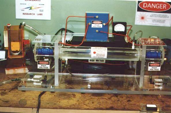
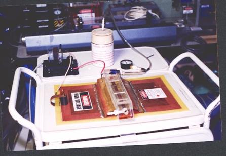
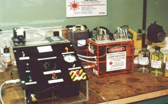
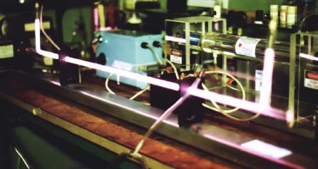