A Home-Built Glass Working Lathe
Version 1.00
Copyright © 2000
J. Lega and Samuel M. Goldwasser
--- All Rights Reserved ---
Corrections or suggestions to: papalega@swbell.net or
sam@stdavids.marconimed.com
Reproduction of this document in whole or in part is permitted
if both of the following conditions are satisfied:
- This notice is included in its entirety at the beginning.
- There is no charge except to cover the costs of copying.
Introduction
A commercial glass-working lathe is a fairly expensive device for
sporadic and limited hobby work.
This is a short description of a home built glass-working lathe which
has helped in the manufacture of glass tubes for pulsed argon and
other lasers.
Although I was able to make hand supported butt seals that were
functional, they looked uneven and were difficult to lineup in the
laser tube support so that the capillary would be centered. I then
decided to manufacture a device that could reduce my lack of skills in
this area.
Description of the Glass Working Lathe
I came across a microwave measurement device manufactured by
Measurements Corporation that had a couple of carriages riding on two
parallel rails. The carriages used linear ball bearings, which made
their riding very smooth and accurate. This was the starting point for
the lathe. However, this could have been manufactured using parts from
W. M. Berg Incorporated. They have a web site with catalog
information. They specialize in hardware of the type needed for this
project, such as timing belts, machined rods, linear bearings, pulleys
etc.
There were several items, which I could not manufacture at home due to
lack of proper machinery. I located a machining shop and had them
made to order. Those were the two pieces of stainless steel schedule
160 pipe and the key on the driven shaft. The other pieces and
components were readily available or were purchased from W. M. Berg.
The carriage end plates were leftover pieces of aluminum from a
previous project. This limited their size and therefore the rotating
clearance. The thickness of the rotating pipes was selected so that
the radial glass holding screws would have enough "meat" without the
need to attach nuts to the internal diameter of the rotating pipe. A
much lighter rotating pipe can be used if screw nuts are soldered to
the inside or outside of the rotating pipe. Make sure that the screws
are radial to the longitudinal centerline of the pipes.
The reader is encouraged to replace components and to find
alternatives to the design and parts shown in this article. The
principle should be maintained: two glass tube holders which run
concentrically, can hold the glass tube centered and one of the
holders needs to move horizontally, maintaining concentricity.
In lieu of the Measurement Corporation carriage, one could use a
dovetail rail if it can be made to ride smoothly in the horizontal
plane. Getting fancy, one could install a rack and pinion drive to the
movable carriage.
Possible Improvements
Here are some suggestions for changes to the basic design:
- A higher throat or tube-to-rail clearance height would be a welcome
addition, if "refurbishment" of broken laser tubes were
contemplated. This would allow, for instance, replacement of the
capillary on tubes, which are already equipped with electrodes. (NOTE:
This would affect the length of the belt) I do not plan to perform
this retrofit, since it requires major re-work.
- Variable speed motor. The original model uses a constant speed motor
that may be too slow for some work, since some glass pieces tend to
droop when heated to high temperatures. I do plan to perform this
retrofit.
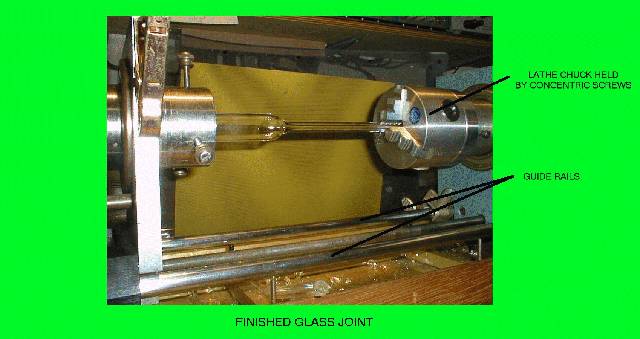
- Use of a metal working lathe chuck on one end. This allows supporting
short pieces of glass, such as the end pieces of the pulsed Argon tube
and sealing electrodes to Pyrex glass etc. This is shown on the
pictures. For a lower cost, a standard 3-jaw drill chuck can be
used. Either can be supported by the radial screws on the carrier
pipe.
The Drawings
The original drawings were developed in AutoCAD and converted to GIF
files. Although the GIF files are adequate, if someone is interested
in the project and benefits from the original drawings, they can drop
me an email and I will attach the drawings to my response. The only
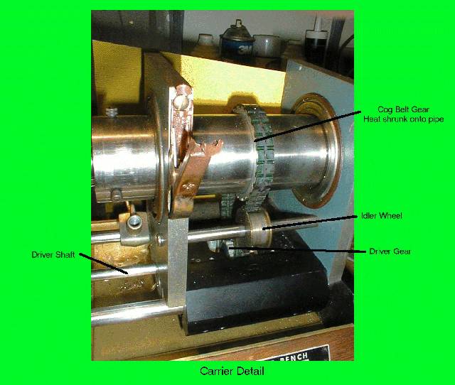
addition to the final product, which is not shown on the drawings, is
an idler pulley on the timing belts. This was required due to a small
amount of slack on the belt, yet not enough to allow the next standard
smaller size belt to be used. The idler is shown on the pictures but
not on the drawings.
Here are the drawings:
-- end V1.00 --