Output wavelengths can be 488.1 nm (blue) and 514.5 nm (green) using argon and 647 nm (red) using krypton. Other colors may be possible.
There are some brief comments by Syl Newmann, the author of the original SciAm article on the pulsed argon ion laser in the section: Experiences of People Who Have Built Lasers From Scratch.
Avoid eye contact with the direct or reflected beam. This includes the 4 pairs of beams reflecting off the Brewster windows which may be quite strong.
See the section: Argon/Krypton Ion Laser Safety for more info. However, the pulsed home-built ion laser uses a different sort of power supply than CW commercial types (unless you are attempting something similar to one of these) so some of the details may not apply,)
For more information, see the chapter: Laser Safety and the more specific information in the section: Ar/Kr Ion Laser Safety. Sample safety labels which can be edited for this laser can be found in the section: Laser Safety Labels and Signs.
Refer to Typical Home-Built Argon Ion Laser Assembly for a simplified diagram of the overall glasswork and power supply electronics.
One source for mirrors might be a surplus commercial ion laser head like the ALC-60X that uses an external mirror tube (see the chapter: Argon/Krypton Ion Lasers). Or, obtain a replacement set of optics for such a head. Typical cost: $150. Note: You would need to make sure f for any concave mirror is large enough since the resonator in this home-built laser is much longer than that in the typical small air-cooled ion laser head. OK, so maybe the optics for a Lexel-88 instead. :)
                                             D1
     H o--------+ T1                T2   +--|>|--+------+------+------o HV+
                 )||               ||=||(  10kV  |      |      |
          Variac )<--------------+ || ||(        |      |      |
          0-115V )||              )|| ||(        |      |      / R1
              5A )||    Neon Sign )|| ||(        |     _|_ C1  \ 2M
                 )||  Transformer )|| || +-------|--+  --- 1uF / 3W
             +--+        5kV,30mA )|| ||(        |  |   |  5kV \ 5kV
             |                    )|| ||(        |  |   |      |
     N o-----+-------------------+ || ||(        |  |   |      |
                                   ||=||(   D2   |  |   |      |
                                   |   | +--|>|--+  +---+------+--+---o HV-
                                   |   |    10kV    |            _|_
     G o---------------------------+---+------------+           ////
Triggering could be done using any of the pulse type HeNe starting circuits described in the chapter: HeNe Laser Power Supply Design but as above using the external electrode rather than a direct connection to the tube anode. Any similar xenon strobe trigger should also work.
However, there are two disadvantages to using a narrow bore:
No other aspect of the laser tube assembly itself is as important as the quality of the Brewster windows to the ultimate outcome of this project! While, certain types of distortion won't prevent lasing (some may even make it more exciting with complex mode structures), this is a complicating factor your first laser can do without.
CAUTION: Apparently, it is possible for an electron beam to be produced from the positive electrode during the high current bake-out step which can quickly melt a hole through the tube wall opposite the side-arm if left running for more than a few seconds. The visual effect will first be a spot of bright yellow sodium light from the point of impact. Use lower current and/or make that area of the tube (the outside of the turn) much thicker.
(From: Mark Dinsmore (dinsmore@ma.ultranet.com).)
I have built the SciAm pulsed argon ion laser and it worked quite well for me. I think that the key for me was having a good diffusion pump vacuum system. Argon lasers like a pretty low vacuum, and it is easy for a small leak to contaminate them. The pulsed version does have lots of gain, as the bore current is quite high during the pulse. I used a set of 1 meter confocal (if memory serves me!) large frame ion laser optics, with about a 5% transmission output coupler. I used the same optics on the Helium-Selenium (HeSe) laser I built, which was MUCH fussier about setup. Gave a nice ~100 mw multimode output with 12 wavelengths from green to violet! I wish I had had some broadband ion laser optics - you can theoretically get more than 24 wavelengths at once covering red to violet!. There's a HeSe laser on the front cover of "Light and its Uses".
(From: Sam.)
So, I wonder why there isn't an article on HeSe lasers in the SciAm collection... See the section: Mark's Helium-Selenium (HeSe) Laser for more info on this laser.
(From: Anthony Paolini (apaolini@cros.net).)
Introduction:
Birth Announcement: It's an Argon! :)
After considerable time and effort, the Scientific American argon laser has finally sprang to life. It will currently generate ultra intense and highly coherent pulses of blue/green light. The repetition rate is about 2 pulses second likely due to the 8 uF capacitor. I will attempt to increase frequency by reducing capacitance to 1 or 2 uF. Another modification in the works is a gas reservoir to stabilize pressure. The vacuum/gas system turned out to be most critical and demanding. Other critical factors are mirror and window alignment. Here are some details.
Description:
The SciAm argon laser is a truly remarkable device and a worthwhile project for any laser hobbyist. It is, in fact, capable of generating the 1 to 2 watts of optical power as the article claims. However, the power is divided among 10 emitted beams. A beam is emitted from each mirror and in both directions from each window face.
In constructing this project, I did extensive experimentation in the use of various components and configurations. These include vacuum, mirrors, transformer, and igniter coils. The purpose of the notes that follow is to give the prospective argon laser builder the benefits of those experiments. This is what I did that worked!
Vacuum:
After experimenting with countless hardware store valves I came to the conclusion that it is not possible to economize on vacuum equipment. My valves are High-Vac type from Kontes. These valves have glass bodies with Teflon seats and o-ring seals. Connections to the pump and laser are through Pyrex to copper graded seals, also available from Kontes. From the graded seals, I used brass range connectors, cutting off the flared ends and silver soldering. The connection to the tube itself is via a #7 Ace Thread and nylon bushing (do not use Teflon bushings as they have a tendency to back themselves out). For any connections that are not soldered, use JB Weld epoxy. It is extremely heat resistant and absolutely vacuum tight.
Mirrors:
I experimented with numerous mirror sets and configurations (very costly). The set that worked best were the CVI Laser Corporation AR1-0537-0-2.00CC and AR1-0537-0-488-514. One mirror is flat and the other has a 2-meter radius of curvature. I had an AR coating added to one mirror, which does significantly improve output. Along the lines of optics is window alignment. This step is vital, albeit simple. With the bore sighted HeNe and mirrors aligned as well as the HeNe will allow, create the "window triangle". This should be done at atmospheric pressure as under vacuum, the ball & socket joints will not move. The windows should be positioned vertically rather than horizontally as per the article. Each window will then reflect the HeNe into the room. At some point, the beams will criss-cross (about a meter from the tube). Rotate the windows until the beam spots coincide. Then, by polarizing the HeNe, the tilt of the windows can be adjusted for minimum reflection.
CAUTION: Do not attempt the pinhole card and spoiler alignment procedure used with the SciAm HeNe laser, as the device has such tremendous ain that the spoiler will not prevent it from lasing.
Power Supply:
Currently, I am using a 7500 VAC, 60 mA current limited neon sign transformer. It is configured with the case as ground and dual half-wave rectifiers as per SciAm. A lower voltage transformer would suffice as the device, when properly adjusted, will actually lase with the variac set to an input of about 25 VAC. Optimum performance occurs at an input of about 70 to 80 VAC.
For triggering, I had originally used the Micro-Mite from Information Unlimited (IU). This is inadequate. The device will lase, but only at about 2 Hz. Although I have not tried a true Oudin coil, the TV flyback transformer with the two-transistor push-pull works very well.
General Operation:
After evacuating the tube, baking out, electrode heating (I used the induction heater, IND40, from IU), and flushing with argon several times, very very slowly admit argon with the Variac input set to 70 VAC. Widely spaced flashes will be observed with the frequency increasing as the pressure comes up. Laser action will begin when the pulses reach about 2 to 3 Hz. This is when mirror alignment should be done (watch the window faces for bright blue-green spots to appear). Optimum power is reached at the point just after the flickering stops, but before a true continuous discharge occurs. It is a fine line between ideal pressure and over pressure that immediately extinguishes laser action.
Comments:
This device has such incredible gain that it seems a waste to spread its output among 10 different beams. I feel a worthwhile experiment would be an internal cavity mirror configuration similar to the popular CO2 laser design. If there are any questions, comments, or experiment suggestions feel free to contact me via Email.
I tried the refrigerator vacuum pump scheme and it was a complete failure. I finally bought a used two stage vacuum pump that was intended for servicing air conditioners. I had to completely disassemble it and give it a real good cleaning to eliminate problems associated with organic contamination. The best thing about this vacuum pump was the electronic vacuum gage and the price.
It took me a year to assemble the new vacuum system. I carefully examined two vacuum systems in a Chemistry lab at U. C. Davis and set up a metal grid system to mount the vacuum system on just like they did. My leak-valve consisted of two all glass stopcocks separated by about 3 inches. The first one was connected to the gas manifold and the second one connected to the laser tube. Using a file I scratched a small line about 45 degrees from the stopcock hole to one side of the stopcock valve parallel with the rotating valve. To "charge" a laser I would pump down the tube and bombard it to remove any impurities. I also use a propane torch to heat the laser tube and vacuum system during the pump-down process. I would then close the stopcock to the vacuum system and open the stopcock on the manifold side of my leak-valve. This would fill the space between the two stopcocks of the leak-valve with gas. I would then close the stopcock on the manifold side and slowly open the leak-valve stopcock that was scratched and connected to the laser tube to allow a controlled amount of gas to enter the laser tube. I had three cold traps consisting of wide mouth thermoses with a glass coil immersed in liquid nitrogen. I got the liquid nitrogen for the cold traps from a welding gas supply company. I doubt that anyone would sell me liquid nitrogen like that today! The three cold traps were used as follows one was between the mercury (!! --- Sam) diffusion pump and the mechanical pump to prevent oil vapor from contaminating the whole system and to keep mercury vapor out of the mechanical pump. The second one was between the laser tube and the diffusion pump and third one was between the laser tube and McLeod gauge. The mechanical pump exhaust was through a hose to the outside of my house.
I had many failures trying to blow glass. Finally, I discovered and purchased a copy of C. L. Stong's "Creative Glass Blowing". (Also see "Neon Signs" by Fink, 1909. It has a lot of information about vacuum systems, glass blowing, and getting a neon tube to work. The technology of 1909 is easy to adapt for home construction.) I practiced by using soda-lime glass and a propane torch. By pure luck I found a scientific glass blower at the University of California at Davis. This guy KNEW how to make stuff!!! Ever see a lathe for blowing glass? One of the first things he taught me was to get the proper goggles so I could see what I was doing. He had a U.S. Army surplus flashlight, one of the ones that are made of green plastic with the business end bent at 90 degrees. These flashlights come with clear, frosted white, and red filters. He installed a plastic polarized filter in the flashlight. The second filter (analyzer) was placed in a lens holder made from #10 copper wire. Attached to the rim of the filter holder was a small bar that was adjustable so that the distance between the two Polaroid filters could be spaced so that the glass he was currently working on would fit between the two polarized filters. The analyzer was adjusted so that the minimum amount of light would be transmitted through both filters. With a polarized light source like this you can see the lines of stress while you are working the glass or trying to anneal it! This tool proved to be the most valuable "Secret" to successful glass blowing I know of. Anyone can make one. I recommend using a car taillight and power supply for a brighter light source. I hope that you will tell others about it! Anyway with his encouragement I made a real nice mercury diffusion pump and a McLeod gage.
I bought my research grade krypton and argon form Lindy gas in 1 liter glass flasks.
My mirrors were from a Spectra-Physics 164 argon ion laser. The reason that I started with an argon ion laser was that I had these mirrors and the complexity of the argon ion laser in Scientific American seemed about the same as the HeNe laser projects. I used a heavy duty ignition coil pulsed by a relay in place of the Oudin coil. All of the lasers that I built using the ball joints had short operational life's, I think due to contamination. I also used TorrSeal to attach the microscope coveslip mirrors. One of the most difficult tasks was trying to accurately cut the ends of the laser tube at Brewsters angle.
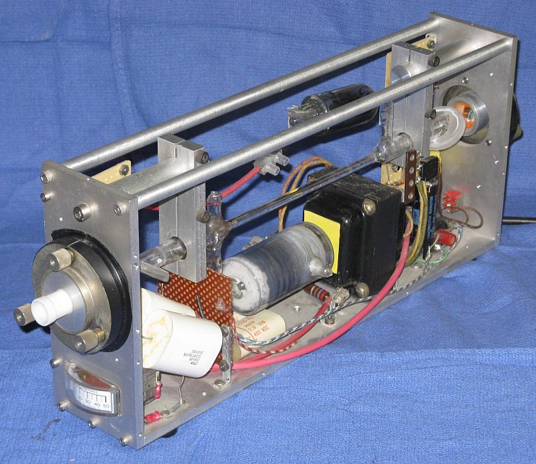
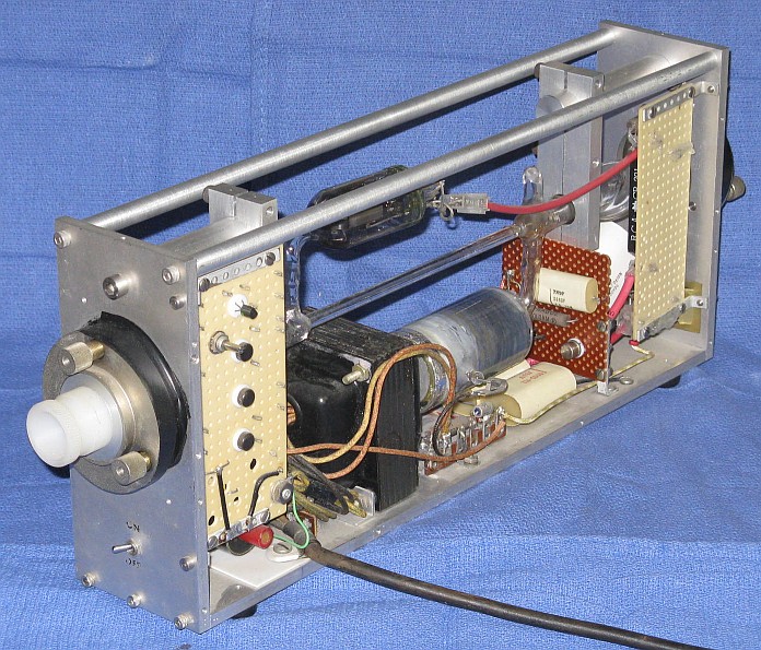
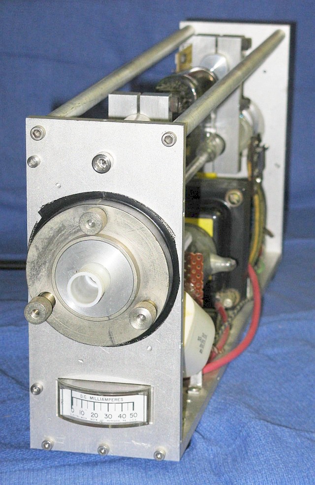
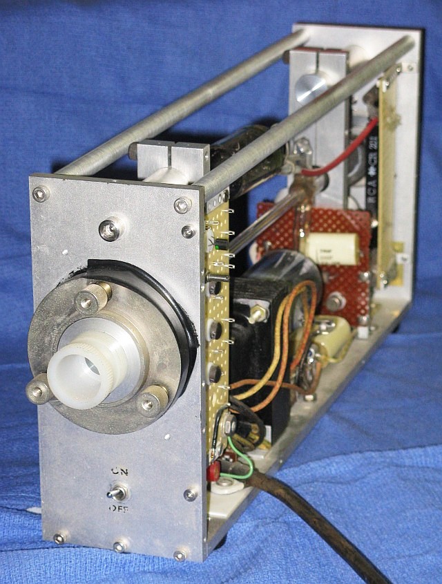
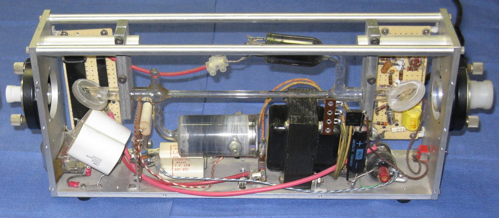
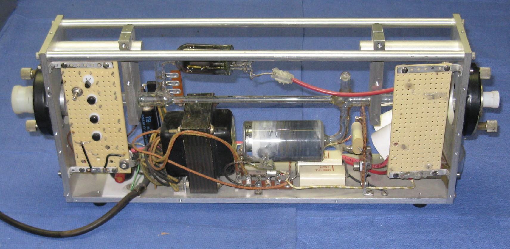
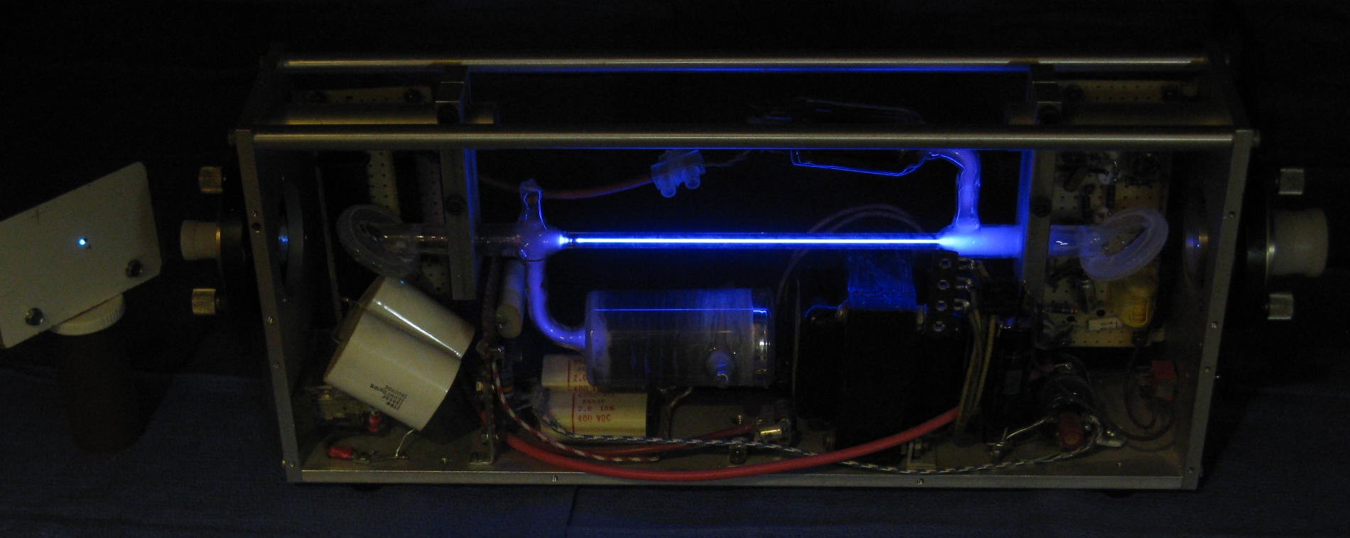
A video made by the person from whom it was acquired can be found at YouTube - Argon Laser from the '60s. Most of it isn't great but the pulsing can be clearly seen around 0:10. Here are some photos:
And side-on (more or less) closeups:
(An explanation about the reason for removal of the sprial-wound wire can be found below.)
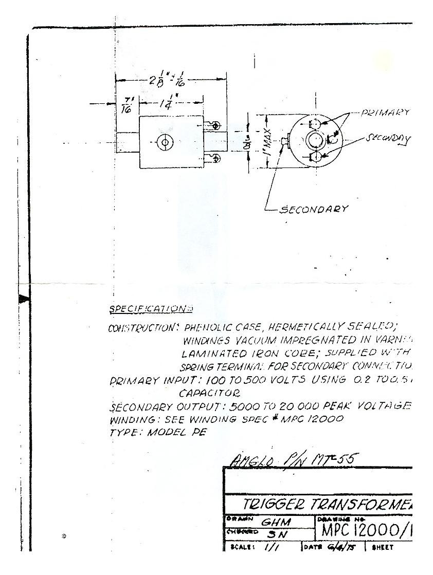
The only "documentation" that came with the laser were photocopies of a partial hand-drawn schematic (with errors) and spec sheet for the trigger transformer:
However, whoever designed this doesn't seem to have had any clue about how basic DC power supplies work, specifically, what voltages to expect on rectifier circuits with filter capacitors. The voltage ratings of most capacitors and the voltages shown on the schematic are way too low for operation at full line voltage, despite the input being clearly labeled "117 VAC". The ratings of the actual parts in the laser are somewhat higher (maybe the original ones blew up!) but still well below the maximum voltages that would be present at full line voltage. For example, the main energy storage capacitors are rated 600 V, but can see around 900 V when fully charged! :) So what were they thinking - or were they? :) Having said that, the parts have survived nicely so far even after roughly 40 years and when the input is pushed slightly beyond 117 VAC. I suppose we should thank the capacitor manufacturers for conservative ratings. However, I would still recommend keeping the input below about 80 VAC.
For the following description, refer to the left side photo and schematic:
On such a potentially lethal device, it might be somewhat surprising that there are no indicators for "power on" or "HV present" and the insulation is between poor to nonexistent in places. However, clear protective covers were almost certainly intended to be part of the package, as threaded screw holes for fastening them in place are present. So perhaps this lack of safety features is understandable. A big red light would still be nice though. :) And there are NO bleeder resistors - I got a shock touching something a day after it had been powered!
Now for some excitement: :-)
Since this is a pulsed laser, these photos don't really show how it really looks in person. But they are good representations of the appearance during each shot. The digital camera simply captures the flash of light in the laser tube and the laser pulse while its "shutter" is open.
It was claimed to be working, and indeed was after a fashion, but while the trigger circuit pulsed reliably, the laser only fired sporadically after the first few shots from a cold start. Originally, there was a trigger wire wrapped around every part of the tube between the anode and cathode but it was grounded at the tube cathode! This is clearly visible in the YouTube video. In fact, despite having a grounded line cord, even touching the frame made triggering worse! I intended to experiment with connecting the trigger wire (possibly via a HV cap) to the anode or to the trigger pulse itself to see if that would help. But simply disconnecting it from the tube cathode resulted in 100% reliable triggering even at very low line voltage. Since the trigger wire was useless, it was then removed entirely, seeming kind of silly to keep it in place like an ugly appendix to potentially cause problems later.
My guess is that the original design used external triggering like a xenon flash but that was found not to be reliable, so they went to the parallel triggering scheme that is shown in the schematic. However, the trigger wire was simply disconnected but never removed. Then someone (possibly the seller, who was not the original owner) grounded it thinking that it had come loose, since it would have just been hanging near the cathode terminal of the tube. But that turns out to make triggering unreliable.
The laser now runs reliably down to below 60 VAC. The lasing threshold occurs at around 45 VAC at which point about 50% of the discharge pulses result in a detectable lasing pulse. The beam is multi-spatial mode with strong lines at 488 nm and 514 nm and weaker lines at (probably) 458 nm and 502 nm. The mirror alignment appears not to be at all critical, but this is probably an illusion due to the apparent use of very precise (if somewhat deceptively ugly) differential screw adjusters.
There was never anything (like rubber boots) preventing dust and contamination from getting on the Brewster windows and mirrors. It lases as long as there isn't a major smudge on the Brewsters, but decent cleaning does help. The mirrors look clean but it was sitting in someone's basement, attic, or storage shed for something like 40 years! The thing was very dusty. Some dust can still be seen in places housekeeping missed like the trigger transformer and vicinity, but that just adds to the ambiance. :-) However, I did have to wipe off the Brewsters before it would lase after being shipped. The mirrors might be soft-coated, so cleaning them is out of the question. Installing modern mirrors is a possibility but then it would not be authentic.
The average power by eye is very low, but so is the duty cycle! I made some measurements using a back biased silicon photodiode with a neutral density filter and oscilloscope. The filter density was selected so as not to saturate the photodiode. The pulse rate is very close to 10 Hz with the rate pot at its lowest setting. At a line voltage of 60 or 70 percent, the width of the lasing pulse is around 5 µs and fairly consistent. Below this, it's rather erratic and the tube still triggers well below the point where there is lasing. So, a 5 µs pulse at 10 Hz is a ~0.005% duty cycle. With a 1.2k ohm load resistor, the voltage of the pulse was about 3 V for a peak current of of about 2.5 mA. At 500 nm (roughly mid-way between 488 nm and 514 nm!), the response of a typical silicon photodiode is around 0.15 A/W, so the peak power through the ND filter would then be about 15 mW for an actual peak power from the laser of about 150 mW. With all the "abouts", "arounds", and other hand-waving, this isn't what you might call rigorous or precise, but I'd be surprised if it's off by more than a factor of 2 one way or the other under this set of conditions. :) It's possible that with clean mirrors and Brewster windows, optimal aligment, and more secure connections in the discharge circuit, the output power would be substantially higher. Interestingly, the peak power doesn't seem to increase linearly with tube voltage or equivalently, energy per pulse into the tube. And using a current probe does reveal some anomalies in the discharge pulse. Depending on the input voltage and unknown random factors, there may be an initial pulse with a peak current very roughly equal to 0.5*Vin amps with a duration of 5 to 10 µs, followed by some residual lower current extending for several 10s of µs. At full line voltage it seems to have a more or less exponential decay from ~60 A but at lower line voltage it might actually go quite low and then increase for a time.
Although I haven't noticed any degradation during testing, I have no idea how many shots this laser has remaining, so I'm reluctant to run it for any extended length of time. And I don't dare turn up the rate pot! Power dissipation in the tube bore doesn't seem to be an issue as it gets only barely warm running for a few minutes at 60 or 70 percent of line voltage. And at full line voltage, the meter reads only around half scale - 25 mA. But as can be seen in the photos, the anode and cathode bulbs look ghastly, though that could have been the way they were originally. However, with many AMPs of peak current, there must be serious sputtering of the cold cathode on every shot, regardless of what it's made of.
The final touch was to install Plexiglas panels for protection of the laser and humans from the high voltage. See Vintage Pulsed Argon Ion Demonstration Laser with Protective Plexiglas Covers.
Specifications (more or less)
("~" denotes "approximately to very approximately".)
(From: Andrew Oxner.)
This is a familiar Brewster window, huh? These were typical of early RCA gas lasers, from around 1970, and persisted until 1978 or so. They are hard sealed quartz!!!
The technique is to grind Brewster’s angle and lay a heavy quartz optical flat on that. There is a deep relief grid of 1/16” just inside the window perimeter to prevent cracking and thermally isolate the interior as it is fused around the outer edge with a hydrogen torch set to a needle point flame. The large diameter is needed to preserve the optical quality of the center. A halo of white silica fume is often seen condensed on the back of these; the front is protected with a graphite disk during fusion. I have the jig that makes these (long story).
There is no glue anywhere in these tubes, and the cathode is an alkali metal (potassium is likely). Unlike helium, that diffuses out of hard glass, argon stays put. That’s why it is still good! These old tubes come in several gas types, few of which will last CW. There was even an oxygen(!?!) variant according to rumor. It can be identified by having an appendix with some kind of salt in it which can liberate oxygen when warmed. I believe RCA made the tube in yours, and a tinkerer or more likely university researcher integrated it.
A modern Ar/Kr ion tube with a 50 cm discharge length would likely be rated at over a WATT - perhaps much greater - when run from a high current power supply. Obviously, since this one is pulsed at a very low duty cycle, the power will be reduced considerably.
For a HeNe tube, a wider bore doesn't necessarily permit higher power since the walls of the capillary are important in depopulating higher energy levels. I don't know how this affects ion laser performance. Therefore, I will assume that this is really equivalent to a 1 mm bore in a modern tube.
Loss factor: 0.5.
For a 30 mA maximum source, a 1 uF capacitor can charge at 30,000 V/second best case. It is not clear at what voltage the tube will fire when triggered or how this related to actual peak laser tube current. There is no ballast resistor. In 1/120th of a second, the cap will charge to to perhaps 450 V (from a tube cutoff of 200 V).
Best case, if the energy represented by the difference between 200 and 450 V when dumped into the tube with the optimum current of, say 20 A, the pulse width would be about 15 us (very wild guess!). Thus, compared to a modern ion laser run on a DC power supply, the ratio of output power to what is possible is about 1:(1.5E-5 * 120) or about 1:555.
Loss factor: 0.9982.
Loss factor: 0.75.
Loss factor: 0.5.
However, the more fundamental problem is cooling.
Here is a set of questions from someone with somewhat grandiose ideas:
"I am a laser hobbyist, and I *really* want to build something which produces a non-red beam. I already have a slew of diodes and HeNe's, but they are all red. I recently found the Scientific American book "Light and its Uses", and it has plans for an argon ion laser. The problem with these plans is that the tube is not sealed and it is a pulsed device with low average power. I want CW, with a sealed tube and a reasonable output. I have developed an idea for a CW argon laser with a ceramic tube and tungsten electrodes. I just have a few questions about the details.I think you are probably biting off more than you can chew for even the low pulsed argon ion laser unless you have already built, say, the HeNe laser from "Light and its Uses". Argon ion laser tubes are not cheap - and for a reason. They have to deal with at least 500 to 1,000 W of heat dissipation in the bore. And this is for the 'smallest' air-cooled ion tubes putting out perhaps 10 to 400 mW. Achieving adequete cooling is extremely NON-TRIVIAL!!!. If you look at photos of commercial argon ion laser tubes (see the chapter: Argon/Krypton Ion Lasers), they are MOSTLY COOLING FINS! The internal parts are made of exotic materials like BeO (beryllium oxide - powder is a serious bio-hazard) and tungsten! For more comments on these issues, see the section: Ion Laser Bore Temperature, Materials, and BeO Warning.
- Is it possible to attach borosilicate windows to a ceramic tube using pottery glaze as an adhesive and firing it at a relatively low temperature (cooled slowly over 3 days) without cracking the windows?
- Also, if I use a 2 mm capillary for the actual lasing area (the discharge passes through it), how long should it be (how long is it in most argon tubes)? Can I use porcelain for this capillary without having it break down from the heat?
- Can a 300 W light bulb filament (tungsten) serve as the cathode if I use a 5 A tube current? Finally, how well aligned do the Brewster windows have to be to avoid excessive beam attenuation?"
You probably won't end up with a sealed tube either - as it will have a very short life.
Then, you need to have a vacuum system, tubing, gauges, the appropriate gases, a 5 A or more 100 V current regulated power supply and igniter, etc.
Light bulb filaments are not designed for emission - they are not coated. You would have to obtain a proper coated tungsten filament. And, of course, a 300 W bulb uses only about 2.5 A so even if you were able to do this and sent current from both ends, you are on the hairy edge. A microwave oven magnetron tube filament might work although these are rated more in the 1 A maximum range - more likely, several in parallel.
I must say that I encourage you to pursue your interests and passions, but perhaps start with something somewhat less ambitious!
However, if all you want is a different colored laser, green laser pointers are coming down in price as are other Diode Pumped Solid State (DPSS) lasers. See the section: Diode Pumped Solid State Lasers. And, yellow, orange, and green HeNe lasers (yes, HeNe lasers come in colors other than red!) are also available. See the section: HeNe Tubes of a Different Color.
If you decide to attempt the argon ion laser, I would probably recommend using a slightly smaller bore - perhaps 1.2 to 1.5 mm which would be closer to that of a commercial ion tube with the same bore length. Then, the current thresholds should be similar and the narrower bore has a better chance of forcing TEM00 mode as well, though I don't know for sure if this would be guaranteed.
There have also been comments that this design won't work at all due to the use of a 0.65 mm ID bore. Aside from difficulties in the fabrication of a laser tube with such a narrow bore (keeping it straight enough, mirror alignment, etc.), there could also be problems with resonator gain resulting in weak or total lack of oscillation. However, I have no idea where the value of 0.65 mm came from. The article in "Light and its Uses" (from the Amateur Scientist column in Scientific American of February, 1969) clearly specifies the bore ID of 2 mm in more than one place. So, unless a change was made without comment when the book was published (I haven't checked the original magazine), there doesn't appear to be any basis in reality for this concern. :)
For more information, see the section: Sam's Three Part Process for Getting Your Feet Wet in Gas Lasers. That procedure was written with HeNe lasers in mind but can easily be converted for Ar/Kr ion tubes. However, depending on what type you acquire, some portions may not apply (e.g., if yours already has Brewster windows for external mirror operation).
And, your next question is probably: "Can I convert a HeNe laser into an ion laser?". The short answer is: forget it! The long answer is: forget it! Nearly everything would need to be changed - mirrors, cathode, power supply. About the only thing you'd be left with is the capillary and that would melt down in about 10 milliseconds unless you were running low duty cycle pulsed mode and that probably is much more trouble than it is worth. I've heard of people torturing HeNe tubes by passing AMPs of current through them. The result isn't something to be discussed in public. :)
Argon ion plasma tubes with Brewster windows for use with an external resonator are widely available both new and surplus. With one of these in-hand, and a matching conventional power supply, you can still experience the joy and frustration of constructing and aligning an external mirror laser head. It then is *just* a matter of fabricating the laser platform and mirror mounts, and obtaining a pair of suitable mirrors. There would be NO excuse for failure!
If you insist on buying new, check out the large well known ion laser manufacturers. The type of ion tube you are interested is probably a small air-cooled model like an ALC-60X. Perhaps, if you can convince them it is for an educational project, they might let you have one that doesn't quite meet their specs for free or at cost. Otherwise, expect to spend several $K! Used and surplus tubes are sometimes offered for sale on the USENET newsgroups alt.lasers and sci.optics, and from the various companies listed in the chapter Laser and Parts Sources. It should be possible to buy one for less than $100 in this manner - but its condition and remaining life may be big unknowns.
However, you them must obtain or build a power supply for your tube. While you can use the same sort of approach as with the totally home-built design - a neon sign transformer based power supply - this would certainly not make the best use of such a tube though it might be something worth doing initially. (Note: These use a hot cathode and a suitable filament supply would also be needed.) And, there is the issues of cooling - very non-trivial for these small air-cooled tubes. Lose cooling for a minute and the tube will likely be damaged if running at even its idle current of a few amps. The advantage of the SciAm style power supply is that with its low duty cycle, cooling is not an issue. Of course, there won't be much output power either especially given the short bores of these air-cooled tubes!
Perhaps, after successfully constructing a laser head in this manner, you will have the confidence to proceed with a totally home-built design.
The opposite situation is also a possibility: Build your own plasma tube but mount it in a used resonator. Depending on your resources, this might be an easier task (though I find that hard to imagine!). External cavity laser heads with dead tubes seem to turn up much more frequently than the other way around (for obvious reasons)! However, in the case of small air-cooled Ar ion heads, both tubes and complete laer heads are readily available at reasonable cost - it is the power supplies that are less common and more expensive.