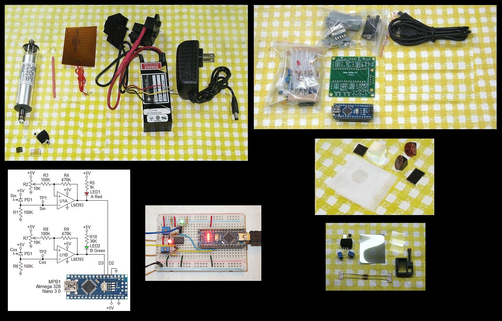
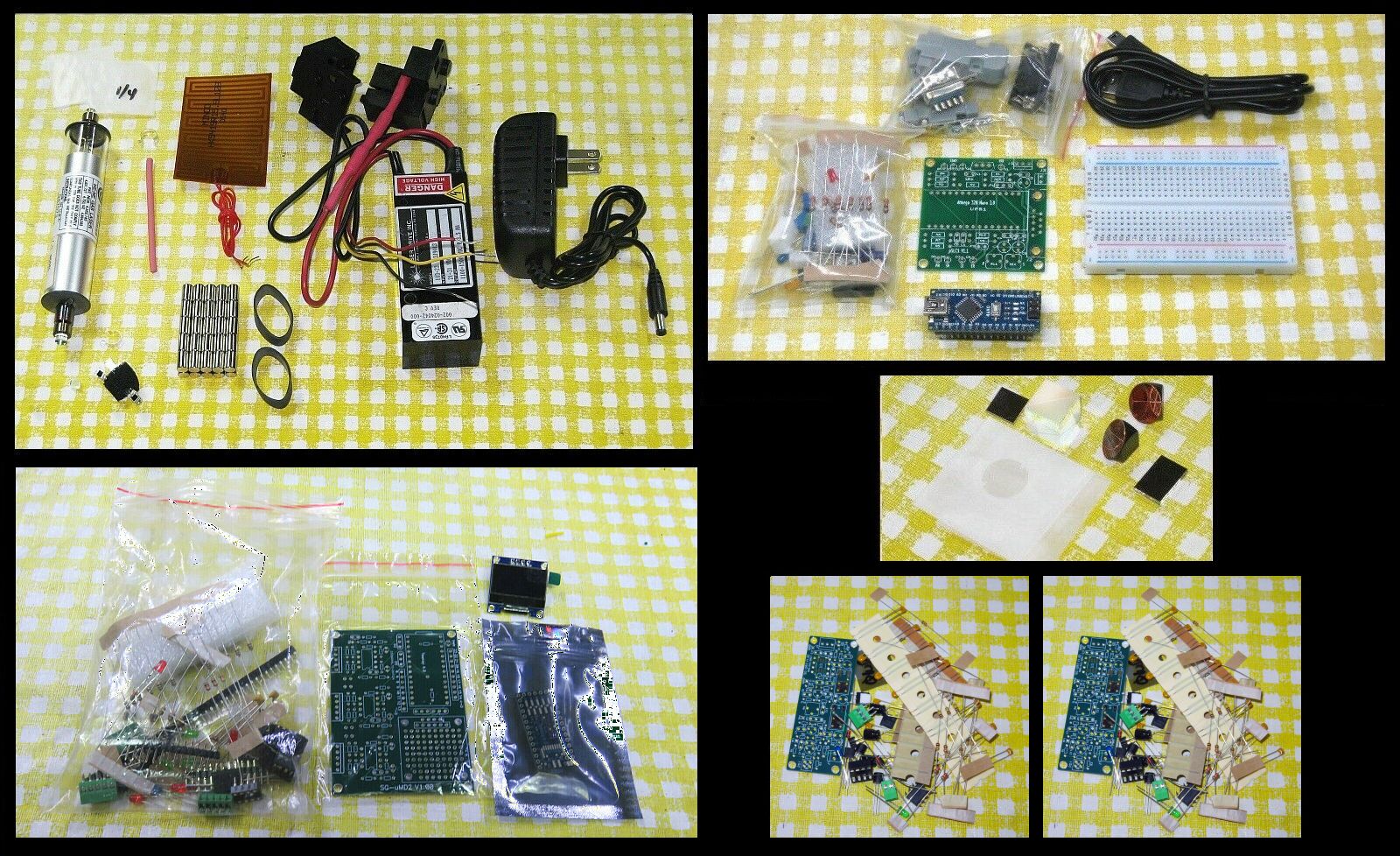
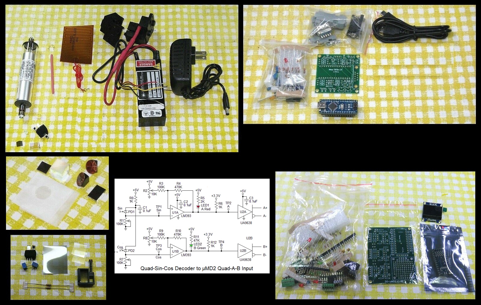
The typical parts are shown below:
Links:
- Stabilized Zeeman HeNe Laser Kit 1
with or without Arduino. The heterodyne kit uses the Arduino version.
- Detectors for heterodyne known as "optical receivers" for these
are SG-OR3 which provide functionality similar to that of the HP/Agilent
10780. SG-OR3 uses a relatively simple PCB so
construction is straightforward and Hathkit™-style assembly
instructions are provided. See Optical Receivers
for Heterodyne Interferometers for more info. Unlike the commercial
optical receivers, these will run on 12 VDC, so no DC-DC boost converter
will be required. (The optical receivers for the "Hewlett Packard (HP)
Interferometer Measurement System-Hobbyist's Special 1,2,3" kits
will continue to be commercial parts.)
- Micro Measurement Display 2 (µMD2).
The typical parts are shown below:
Links:
- Stabilized HeNe Laser Kit 1 with
Arduino
- Construction Guidelines for Basic
Quadrature-Sin-Cos Decoder and Quad-A-B Interface Kits.
- Micro Measurement Display 2 (µMD2)
The detector in all the homodyne kits is quite primitive consisting of a pair of biased photodiodes with a Quarter WavePlate (QWP) to shift the phase of one of the signals by 90 degrees. Thus the bandwidth is quite limited. But a better one could be constructed relatively easily.
Parts for a simple Quad-Sin-Cos to Quad-A-B converter with RS422 drivers for µMD2 are included. The schematic is shown in the above graphic. There is no PCB for this but a Perf. board is provided on which it can be constructed. A solderless breadboard could also be used. available for a couple bucks on eBay. The RS422 drivers at the output can be dispensed with if µMD2 is set up for single-ended inputs as described in its assembly manual.
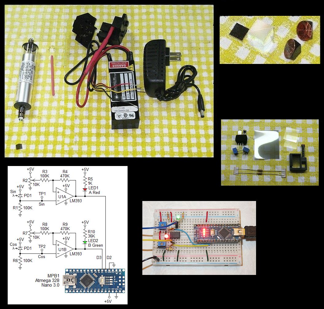
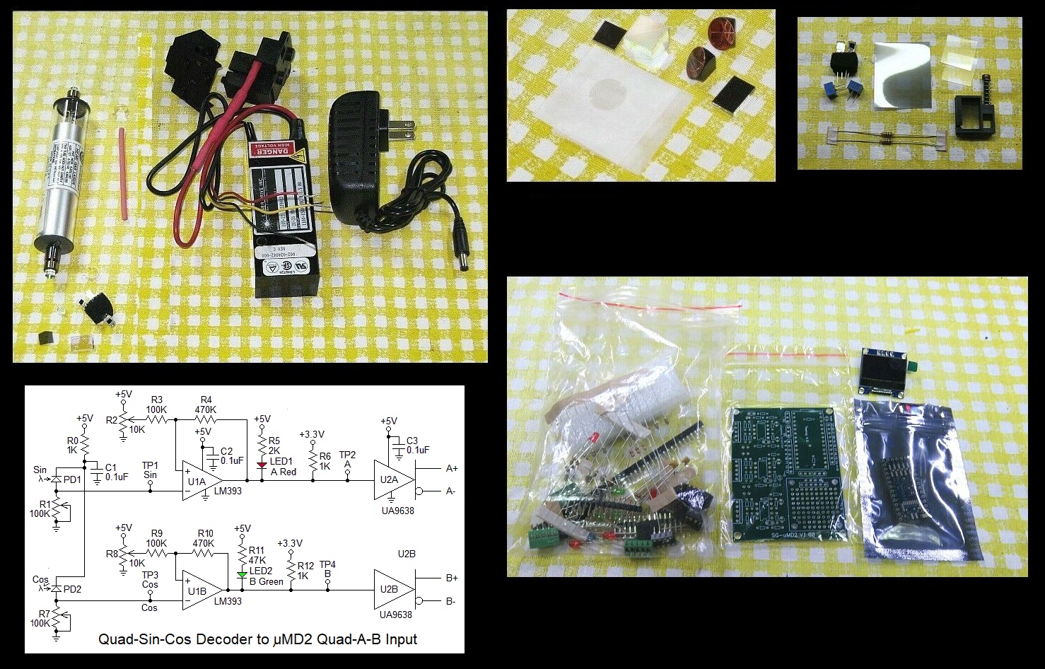
These lasers produce a narrow beam (less thatn 1 mm in diameter), but because the PLD needs to be small, the diameter at the detector should be similar for both the reference and measurement beams. However, if desired, a beam expander can be added. Ask.
Note that while this kit has the µMD2 measurement display, the performance is limited mostly by the frequency response of the Quad-Sin-Cos detector, which is quite limited. So it may be no better than the minimal version using µMD0.
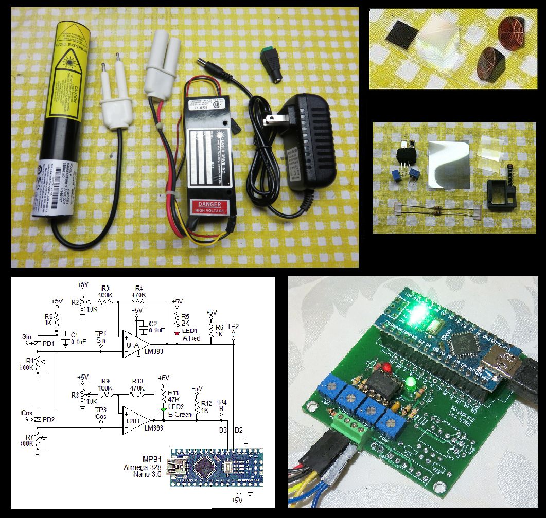
The typical parts are shown below:
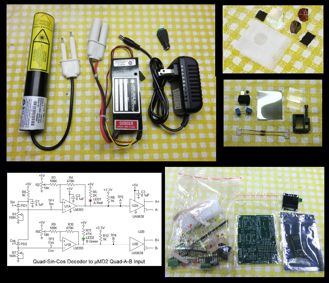
Plug the high voltage "Alden" connectors of the laser head and power supply together securely if not already attached. The power supply will probably have a DC connector so it just needs to be plugged into the included wall adapter.
Orient the laser head so that the polarization axis is at 45 degrees. It will probably be marked but if not, is easily determined with a linear polarizer.
Links:
- Construction Guidelines for Basic
Quadrature-Sin-Cos Decoder and Quad-A-B Interface Kits.
- Micro Measurement Display 2 (µMD2)
Since switching between Het and Hom requires reconfiguring the laser itself, among other things, the combined kit is not really recommended and currently disabled in the eBay listing. But if really interested, contact me.