For more information, see:
This document contains notes on the construction of a two-frequency Zeeman HeNe laser using the set of parts in Stabilized Zeeman kits. Note that there are a superset of the one or two mode stabilized HeNe laser kit so a non-Zeeman stabilized HeNe laser can also be constructed from these parts if the HeNe laser tube satisfies certain requirements (not all do).
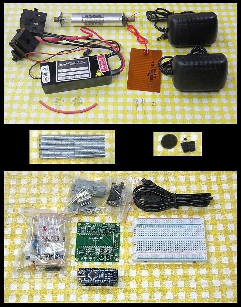
(The style of some parts may vary slightly from what's shown in the photo and the parts in the bottom pane are only present for the Arduino version.)
The following laser components are included (top pane of photo):
There will be at least the number specified in the eBay listing of these.
This is due to the fact that the output of a Zeeman laser tube is usually NOT pure circular polarization but elliptical, so it includes a superposition of circular and linear polarizaton. In order for the result after the QWP to be pure linear polarization with orthogonal axes, the linear components must line up with the QWP's optical axes to pass through unchanged or else they would end up elliptical but will be at a 45 degree angle relative to the converted circular polarized input. Since these are mutually coherent, they will add at the output resulting in pure linearly polarized orthogonal components at some arbitrary angle determined by their relative intensity. Or something. ;-)
However, the behavior of these WPs is not symmetric at 633 nm like the mica ones above, or normal QWPs designed for 633 nm. Converting pure combined left and right dual circular polarization from the Zeeman tube is clean with clearly defined axes and good orthogonality as noted above once the orientation of the QWP with respect to the tube has been optimized (which is normal). But in tests with a linearly polarized laser (essentially 1 component of the two frequency laser's output), the conversion in the reverse direction (regardless of which side the beam enters) does not behave like a QWP. If a polarizer is set at a 90 angle to the laser's polarization axis so the beam is totally blocked, the output following one of these QWPs inserted in the beam path will vary in intensity depending on the WP's orientation but never approach 0 indicating that there is always significant elliptical polarization in the output. With a normal QWP, the beam would be totally blocked when oriented so that one of its optical axes is aligned with the laser's polarization axis. These QWPs were designed to work at 3 wavelengths in a Blu-ray optical pickup - 405, 650, and 780 nm. My hypothesis is that the peculiar non-reciprocal behavior is a byproduct of this but a proof is above my pay grade (or at least my level of determination). :( ;-)
Here are some more specific tests at 633 nm using a single polarized component:
                       WP Handle
  Input Polarization  Orientation  Output Polarization
 -----------------------------------------------------------------
       Circular        45 degrees  Linear, 45 degrees, >25:1
  Linear, 90 degrees   45 degrees  Linear, 0 degrees, >100:1
  Linear, 90 degrees   90 degrees  Elliptical, 90 degrees, ~3.5:1


 Perhaps useful, but interesting if nothing else.

 It's possible that at the design wavelengths including 650 nm these are better
 behaved but that isn't really useful here.
The following control components are included in the Arduino version ONLY (bottom pane of photo):
See important CAUTION about powering the Atmega board in the µSLC1 manual. Specifically, DO NOT power the board using +12 VDC to VIN at the same time the USB is plugged in. Only use 12 VDC for the heater. While this is supposed to work, doing so killed (probably) the USB chip on one of my Atmega boards when the 12 V supply was switched on. The cause is not known. When the controller is NOT attached to USB, then it's OK to use VIN to power the board.
What you will need to provide:
To fit the tube with magnets in the mounting scheme, it may be necessary to trim the mounting brackets, or do away with them entirely and use tube clips (included). This is recommended as the brackets limit the available space for the magnets.
But with the Arduino version of the kit, once the µSLC1 Arduino controller with the Windows GUI is operational, it can serve this purpose.
Organization of two-frequency Zeeman-split HeNe Laser:
The diagram below shows a system similar to what may be constructed using parts in this kit and readily available materials and electronics.
Many variations are possible. The Arduino implements the electronics inside the box. The REF Signal monitor is shown using the waste beam but could also be in the main beam (the polarizer would then need to be at 45 degrees). However, that would require an additional beam sampler plate (not included) which would decrease the output power slightly.
Power and wiring:
Follow the link to the type of power supply and adapter that was included in the kit:
As noted there are two beams from the tube. The main beam is the stronger one (typically by a factor of 25-100 or more) than the "waste" beam. Which end of the tube is which is set at the time of manufacture. For the tube in the kit, it will need to be determined as both types have been shipped at times. Most of the 6 inch tubes have anode-end output while all the 4.5 inch tubes have cathode-end output. The output beam emerges from the end with the AR coating, which appears blue-ish in reflection. However, it may be the anode or cathode-end. Also as noted, the tube MUST be oriented so the glass-end is wired to the positive (red wire with ballast) of the HeNe laser power supply or else bad things will likely happen.
Since the waveplates are required to convert circular to linear polarization, there are two waveplates included in the kit. However, the waste beam can be used for the internal REF detector if desired requiring only a polarizer and eliminating one beam sampler.
Installing the heater:
The long dimension of the 2x3" heater should be wrapped around the tube so it covers nearly the entire circumfrance or may slightly overlap. Thus The Kapton heater has an adhesive backing. Peel off the backing paper and stick it on centered between the two end-caps. For convenience (this is sort of arbitrary) orient it with the wire connection point lined up with the tip-off (the small metal tube where the air was removed and the gas was inserted). Press it firmly in place over its entire surface. Route the red wires toward the cathode-end of the tube. Where the wires attach is lumpy. Allow this to poke out a bit rather than squashing it against the tube which may damage the connections. Wrap some high temperature tape around the heater to keep it secure, but only at most one layer so as to allow heat to pass to the environment.
Determining the polarization axes of the tube (optional):
This step is only really required if it is intended to use the tube in a (non-Zeeman) stabilized laser. When installed in the magnet, the tube orientation is not critical. However, this is a good exercise in becoming aquainted with mode sweep and how the longitudinal modes behave.
NOT ALL TUBES will work for a non-Zeeman one or two mode stabilized laser, at least not trivially. The tube must have well behaved longitudinal modes. Specifically, it should NOT have polarization switching, also known as mode flipping. It's often possible to use flippers for non-Zeeman stabilization but it adds complication. Since flippers actually seem to work better for Zeeman, the tube in this kit may be a flipper unless it was purchased to be usable for both single frequency and Zeeman applications. But even it if is a flipper, experiments and stabilization without the magnets could still be interesting. So, it would be worth determining the polarization axes of the tube and labeling them. A flipper will still have polarization axes but the change in mode amplitude will not be smooth but will abruptly change intensity, usually at some specific point during the mode sweep cycle.
As noted, the laser tube actually produces 2 beams: A strong one out the anode-end (front) and a much weaker one out the cathode-end (rear). For use in a conventional stabilized laser, the beam sampler can be constructed behind the rear of the tube and use the weak beam. As a side benefit, this is the low voltage end of the tube so shocking experiences will be minimized. For use with the Zeeman laser, a QWP must be inserted between the tube and PBS cube oriented with its optical axis at 45 degrees to X or Y. Alternatively, a beam sampler can be added in the output beam after the polarization has been converted to linear. In principle, using the main beam will have slightly better stability, especially for some tubes but in practice, do whatever is more convenient. I prefer to make use of the waste beam for feedback.
Place the PBS on a support so the main beam passes through its center and a deflected beam shoots off to one side. Eventually the PBS will need to be mounted securely, but for now, a block of wood or stack of CDs and CD boxes will suffice. :)
Use a white card as a screen to observe the beam coming straight through the PBS and the beam being reflected to the side. They will vary in intensity along with the polarized modes coming out the front. Adjust the tube orientation so they alternately go completely dark periodically and label the tube with with that result.
The power varies because the longitudinal modes of the laser cavity are moving through the neon gain curve as the tube expands due to heating. The roughly bell-shaped gain curve results in gain variation depending on its height. If 5-10 VDC is applied to the heater (between the two red wires), the rate of the mode sweep will greatly increase since the tube is expanding faster.
As the tube/heater combination approaches thermal equilibrium where the power input from the electrical discharge in the bore of the laser tube and heater power are balanced by heat loss to the environment, the mode sweep will slow down and eventually stop. If power is removed from the heater at that time, the discharge heat alone will no longer be able to sustain the same temperature, the tube will start to cool, and the mode sweep will reverse.
This shows the mode sweep from a cold start of a tube similar to the type included in the kit.
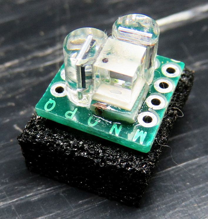
To provide the feedback signals, one of the photodiodes will be placed behind the PBS cube and the other on the side. Devise mounts for the PDs so each of the beams strikes its respective PD and any reflections do not go back into the tube. They can even be glued to the PBS with the entire assembly mounted at a very slight angle to avoid back-reflections.
For thermal stabilization to be effective, what is desired is where a modest amount of heater power is needed to be at thermal equilibrium. Perhaps 20-30 percent of the power in the bore discharge. For the 6 inch tube running at at 3 mA, 900 V, the bore discharge power is just under 3 W. So, 1 W of heater power should be sufficient to allow the laser to stabilize with reasonable immunity to ambient temperature changes. Using a 3 or 4 VDC power supply, it should be possible to simulate the action of an electronic feedback circuit to confirm that stabilization is possible.
A purist might object (due to noise considerations), but this means that a single 5 or 6 VDC power supply could be used for both the HeNe laser power and the stabilizer. However, this kit includes a 12 VDC power supply intended to be used for the heater.
Note that the tip-off may prevent orienting the tube optimally within the mounts. (This is most likely with the short tubes which tend to have a longer tip-off than the long tubes. If that is the case and the mount cannot be modified to be usable by removing some plastic, then either the PBS will need to be mounted at the appropriate angle, or a different mounting scheme will be required for that end of the tube.
Installing the Magnets:
CAUTION: These are powerful rare earth magnets. Keep them well away from any magnetic media or other magnetic-sensitive objects or devices including small children. Since they are small, flesh squashing isn't a major concern but they still can do damage.
The magnets can be arranged in a variety of ways. The one that has been tested and found to be satisfactory is 7 sets of 7 magnets spaced equally surrounding the tube. They must all be facing the same way, N-S field direction-wise. Whether N or S faces the output isn't critical but will flip the error signal so once a direction has been selected, stick with it. This arrangement of magnets should result in a peak split (or beat) frequency of 0.9-1.1 MHz. However, it's possible that an arrangement of, say, 10 sets of 5 magnets might be even better. Or if a higher split frequency is desired, obtain some more magnets. That's for you to determine if interested. :) But there is a limit to the strength of the magnetic field above which so-called "rogue modes" will develop and the split frequency waveform will become asymettric or worse, and the actual frequency itself will probably not increase. Rogue modes are not likely to be present using the magnets included in this kit, but they could if trying larger rare earth magnets.
[The best way to check for rogue modes is using a Scanning Fabry-Perot Interferometer (SFPI, also known as a Laser Spectrum Analyzer), which can be built using parts that are available in another of my listings. The basic SFPI will not have enough resolution to actually see the individual modes whose difference in optical frequency produces the split frequency, but it will easily show if any other modes are present that shouldn't be there.]
The objective should be to provide a fairly uniform field over the entire extent of the discharge inside the tube's bore. The magnets should actually extend slightly beyond these points since the field declines to 0 at the very edge of the magnets (and then reverses). For the tubes in these kits that means from very near the anode end-cap to somewhere around the center of the cathode can. The arrangement with 7 sets of 7 magnets fulfills this requirement, more or less. ;-)
In order for the magnets to cooperate and not jump out of position, each "stick" should be wrapped with 1" Kapton (preferably) or packing tape. Then they can be secured surrounding the tube using slices of bicycle inner tube or tape. Provide adequate insulation so there can be no chance of the high voltage at the anode-end of the tube arcing to the magnets even if they shift position. A sheet of the type of thick clear plastic often used to package grocery items works well here as shown (slightly squashed) below.
The tube can be slipped inside and be close to the magnets without fear of short circuits or arcing.
It may be possible to increase the effective magnetic field - and thus the split frequency (up to a point) - by adding pole pieces at both ends of the magnet array - soft iron rings or the like. However, care must be taken not to boost the field too much. There is there a limit to how high the split frequency can go before "rogue" longitudinal modes are produced resulting in the inability to be locked and poor performance in an interferometer. With the six inch tube and 7x7 magnet array there should be none. A Scanning Fabry-Perot Interferometer (SFPI) can be used to confirm rogue mode-free behavior. Much more on rogue modes via the links, above. Being able to go above around 1.5 MHz with these tubes is unlikely.
This shows a similar tube inside the magnets but with electrical connections for an HP laser.
Alternatively, the tube can be installed with insulation inside a non-ferrous cylinder as in the complete Zeeman laser shown below.
Rare earth magnets are more sensitive to heat than Alnico magnets, so if installing a heater surrounding the tube, keep the array of magnets slightly away from it with air or plastic in between.
When powered with the magnets in place, the appearance of the glow of the tube and laser beam won't be noticeably different by eye, though power variation during mode sweep and actual output power may change enough to be easily detected. The fun will begin when using simple instruments. Here they are actually secured to an aluminum cylinder inside which the tube and heater (well insulated) is installed.
The Quarter WavePlates (QWPs):
The raw output of the HeNe laser tube in the Zeeman magnet consists of lasing modes that are left and right circularly polarized. For these to be useful for stabilization feedback and in an interferometer, it is necessary to convert them to orthogonal linearly polarized modes. This is normally done with a Quarter WavePlate (QWP) oriented with its optical axis at 45 degrees to the base (X and Y axes).
A pair of optical quality mica QWPs is included in the kit. THESE ARE VERY THIN AND FRAGILE so extreme care must be exercised in handling. In the envelopes in which they are packaged they are virtually invisible. It is recommended that the first thing to be done is to mount them on a supports like metal washers with a few dabs of adhesive around the periphery. The optical axis may not be readily apparent if it is marked at all, so the orientation will generally need to be determined by testing while monitoring the mode behavior of the transmitted beam(s). This will be done using µSLC1 and/or a laser power meter or equivalent.
If using the main beam for both feedback and output as in the diagram, a single QWP will suffice to convert to linearly polarization. But if using the waste beam for feedback as in the photo of the completed laser, QWPs will need to be installed at both ends of the tube.
Since the beam is less than 1 mm in diameter from the laser tube, only a small portion of the QWPs are actually required. So, they can be cut into several pieces if desired to conserve QWP availability. ;-)
Optimization of the QWP orientation will be done below.
Constructing the beat detector:
                                  PD
          +5 to 9 VDC o-----------|<|---------+--------o Output
                                 C   A        |
                                              /
                                           R1 \         Scope or
                                              /         Counter
                                              \
                                              |
               Return o-----------------------+--------o Ground
The suggested value for R1 is 2.7K which is a compromise between largest amplitude and frequency response. Feel free to experiment with higher or lower values.
Test the tube for Zeeman behavior:
Temporarily install the tube inside the magnet array with adequate insulation to prevent shorts or arcing at the anode end. It should light up within a few seconds, and to the unaided eye, will appear to lase normally. Aim the main beam through the polarizer to the PD.
Use the beat detector to view the Zeeman beat or measure its frequency from the tube in magnet. A polarizer must be placed in front of the PD but without the waveplates, its orientation doesn't matter.
This shows the bare tube snug with its heater inside a plastic sleeve with 7 sets of 7 rare earth magnets secured to it with slices of bicycle inner tube, along with a polarizer and a built up version of the beat detector in the schematic, above, with a swing arm and 9 V battery inside. The position of the magnets along the tube was selected to maximize their overlap with the active bore discharge, resulting in the highest peak split frequency. As the tube warms up and the cavity length increases, a beat will appear periodically during mode sweep at a frequency peaking around 1 MHz for the 6 inch tube and the set of 49 rare earth magnets. The beat will probably be present between 50 and 75 percent of the cycle, and will change frequency somewhat during this time. With a greater magnetic field, the percentage of the cycle over which there is a beat decreases. For example, it may be less than 10 percent for an HP-5517D laser which locks with a ~3.75 MHz split frequency.
If 5-10 VDC is applied to the heater, the rate of the mode sweep will greatly increase since the tube is expanding faster. The short video on the right shows the output of the back biased photodiode behind a polarizer using the rig in the photo on the left with around 10 V applied to the heater shortly after the tube was powered on.
Due to asymmetries in the tube, optimizing the orientation of the QWP that converts circular to linear polarization and tube will need to be done once a beat signal can be displayed. Even if the polarization axes of the tube have been determined (above) for use in a non-Zeeman stabilized laser, they won't necessarily be related:
Since the tube isn't locked and stabilized, the beat will come and go due to mode sweep as the tube warms up and expands, so you will have to catch it each time. ;-) Mark the orientation of the tube so it can be installed later the same way.
Note that while µSLC1 has a split (or "REF") frequency input which will display in the Main Window of the GUI, it requires a TTL-compatible signal. This can be generated by an HP/Agilent optical receiver or an equivalent home-built circuit. This kit currently doesn't include parts for that, sorry. A simple circuit that should be suitable can be found at Teletrac 150 Reference Receiver Schematic. Either REF or REF- can be sent to the µSLC1 REF input. DO NOT connect an optical receiver like an HP-10780 or SG-OR3 with an AC-coupled signal directly as bad things may happen.
Mounting the tube in the Zeeman magnet:
Now mount the tube/heater assembly more permanently inside the set of magnets making sure to provide adequate electrical insulation. There should only be minimal thermal insulation - one layer of Kapton tape. The tube needs to be able to dissipate heat to the environment for the stabilization to be effective. In addition, it needs to be able to expand and contract so it should NOT be attached rigidly. But since the total change in length is a fraction of 1 mm, this should not be a problem.
Eventually, the QWPs will need to be added but that can wait until there is a convenient way of monitoring the outputs.
Testing the photodiodes response to laser light:
The following assumes that the QWP has been installed to conver the circular polarization to linear polarization and the resultin polarization axes are known.
To test the response of the silicon PhotoDiodes (PDs) included in these kits, a simple test circuit using a few resistors, a 5 VDC power supply (or USB charger cube), and DMM can be constructed before connecting the stabilization controller. To determine the polarity of the PDs, use the DMM on the "Diode Test" range across the pins: The voltage drop will be between 0.5 and 0.6 V if the red probe is connected to the anode. The polarity is usually opposite for a VOM but they are only found in museums these days. ;-)
Wire up a test circuit as follows:
                                  V1
                                   o
             R Protect       PD1   |  R Load 1
   +5 VDC o----/\/\----+-----|<|---+---/\/\-----+
                       |                        |
                       |          V2            |
                       |           o            |
                       |     PD2   |  R Load 2  |
                       +-----|<|---o---/\/\-----+
                                                |
                                                |
  GND/RET o-------------------------------------+
CAUTION: If the PDs are at the anode-endo of the tube, take care to keep the setup at a safe distance as they won't like being zapped by the high voltage. Nor will you. :( :)
Note that with the magnet installed, the appearance of the mode sweep is distinctively different than it is without them.
Closing the loop:
To stabilize the laser so that the position of the modes is under automatic control with a Zeeman beat requires some electronics to first run the tube in "Preheat Mode" so that the temperature of the tube/heater combination levels off somewhat above ambient, and then to "Lock Mode" to allow the output of one or both photodiodes to take control.
If you're willing to switch from Preheat to Lock mode manually, the required circuit can be as simple as 2 basic electronic components - a resistor and a power MOSFET. This won't have superior performance but is quick and easy to get working and therefore will provide nearly immediate gratification. :)
However, the Arduino kit includes components to construct a fully automatic controller using an Atmega Nano 3.0 Arduino-compatible microprocessor platform.
Assembly of the electronics and operation of the µSLC1 Windows GUI may be found in the Micro Stablized Laser Controller 1 (µSLC1) Installation and Operation Manual.
However, unlike the non-Zeeman case where one can lock on either side of the gain curve depending on the polarity of the error signal, with the Zeeman laser, there is only one place to obtain a beat. In other words, it's possible to lock so that the two components - F1 and F2 - are equal in two locations. One is where the Zeeman-split longitudinal mode is between the split gain curves and there will be a beat. The other is where there are actually two separate (non-Zeeman) longitudinal modes with equal amplitude but far far away at the longitudinal mode spacing of the laser tube. In that case, there will be no beat without a fancy high speed detector since the frequency would be over 1 GHz.
Adjusting the QWP:
Perpare to install the QWP between the tube and PBS beam sampler. While monitoring the horizontal and vertical mode signals from the PBS, rotate the QWP until the two signals are most different. They should look something like the screen shot below.
The ragged green and orange plots of of the modes is characteristic of Axial Zeeman behavior. The QWP orientation should be set to maximize their amplitude.
If using the waste beam for feedback, test and adjust both QWPs and label their orientation. Then transfer one to the main beam using the same orientation. Whether the waste beam has enough output power depends on the specifif laser tube. Only testing will determine for sure.
Enhancements/experiments: