For contact info, please see the Sci.Electronics.Repair FAQ Email Links Page.
Copyright © 1994-2024
Reproduction of this document in whole or in part is permitted if both of the
following conditions are satisfied:
1. This notice is included in its entirety at the beginning.
All Rights Reserved
2. There is no charge except to cover the costs of copying.
DISCLAIMER
Although working on cameras is generally
less risky than dealing with microwave ovens, TVs, and computer
monitors, there is one component in every camera with an electronic
flash - even the least
expensive throw-away variety - that is potentially lethal. Specifically,
it is the energy storage capacito.
And of course even more so for separate electronic flash units
or "speed lights" with their higher energy.
This may charge up as soon as power is turned regardless
of whether flash is called for, and may retain a dangerous charge for hours or
days. If working inside a camera or flash unit, on one that has
had its case damaged exposing internal parts, it is essential that you
read, understand, and
follow all safety guidelines contained in this document and in the document:
Safety Guidelines for High Voltage and/or Line Powered
Equipment.
If there is no electronic flash, the greatest risk is torn flesh from sharp sheet metal or gear teeth. ;-)
We will not be responsible for damage to equipment, your ego, county wide power outages, spontaneously generated mini (or larger) black holes, planetary disruptions, or personal injury or worse that may result from the use of this material.
Note that technically, these have specialized JIS (Japanese Industrial Standard) screw heads but the Husky 00 bit fits them perfectly. The only issue with stripped heads I have encountered is where someone was inside the lens before me.
For the specific case of the (mostly older) flat head screws, fabricating a driver with an aluminum blade is recommended to prevent damage to the screw slots. These screws also tend to have long thin slots, which don't fit the typical screwdriver well at all. The special tool can be as simple as an aluminum roofing nail with its point filed down to a thin blade. Damage to the screw slots is almost unavoidable with a steel screwdriver, and at the very least, looks bad. ;( The softer blade will get chewed up after a while but that can be repaired.
Most in modern Nikon cameras and lenses are self-tapping plastic screws with a coarse thread. For the few metal parts, they are fine-thread machine screws. There are several sizes used and they are not interchangeable! So it's best to keep track of the specific screws at each step by storing them in plastic baggies. Pill organizers are also useful but an accidental whack can send the screws all over the place. ;-(
NEVER use excessive torque in tightening screws! It doesn't take much to strip threads in soft plastic, especially for the tiniest screws. And take care not to start the screw at an angle and cross-thread the hole. There will be definite resistance but should never be an indication of bottoming. That probably means the wrong screw length was used. If it seems more difficult to install than to remove, it's probably the wrong screw.
A very few screws in cameras have a left-hand thread. I've seen exactly one (1) case of this - in the Copal Square S shutter (used in the Nikkormat FT/FTN among others) - which secures the "Slow Speed Lever" or "Retard Drive Cam" depending on which manual is being referenced. But be on the lookout - if the screw seems to get tighter, try the other way. ;-) Being overzealous and breaking or stripping the screw shaft would likely be fatal to the camera both because finding a replacement screw would be impossible and the remains of the screw is solidly stuck in the hole. ;-(
Other Websites may have manuals not there. One example is All About Photographic Lenses, though some of the links appear to go to a Russian Website. ;-( Some manuals may not be free so make sure that a free download site hasn't been overlooked. Even so, sometimes there are enough free "Preview" pages to be useful. Or the typical cost of under $10 may be worth it if you are really serious about tackling a dicey repair.
Another is ElectroTanya, which has manuals at present elsewhere. And it (as of early 2026) is currently free for up to 10 downloads/day.
However, beware of suspicious links - it's not worth the risk of infecting your computer. ;-( If your browser or AV software raises a red flag, stay away!
Note: One would think that when shooting with a DSLR in "live view" mode (which uses the sensor with the mirror up) it would behave like a point-and-shoot and be silent if the simulated shutter sound is turned off. But this is usually not the case for technical reasons having to do with the way the sensor reads out data: The mirror flips down and the mechanical shutter closes, then it opens for the exposure and closes after the exposure, and then the mirror flips up, and the shutter opens. That's why the entire sequence of events when pushing the shutter button takes a lot longer and is noisier with live view. Try it! ;-(
Mirrorless cameras are essentially the professional versions of point-and-shoots with a high resolution LCD viewfinder instead of an optical viewfinder (in addition to the normal LCD display) both fed from the main sensor. And a price tag 10x to 100x higher. ;-) Having said that, mirrorless is where manufacturers are putting their R&D effort now with no future offerings likely in DSLRs. And having now experienced Mirrorless, I can say with certainty that budget permitting, you won't want to go back to a DSLR.
In the end, the quality of your photos will depend more on care in composition, lighting, a steady hand, and other factors not part of the camera itself. Technology can help but it doesn't replace these. No matter the cost of the equipment, if the lighting is not balanced or the depth of field is too shallow, the photos will be poor.
And as a practical, with high-end photo gear having so many options, there are many more ways to screw up the resulting photos. Even the default out-of-the-box settings (e.g., "Program" or "Auto") may result in photos inferior to those from your phone or $100 Point-N-Shoot.
40+ years ago I owned top-of-the-line Nikon film SLRs including the flagship Nikon Photomic FTN body with several Nikon fixed focal length lenses. Zoom lenses were a pricey extravagance back then. The FTN body alone was around $350 in 1970s dollars, which would be comparable to roughly $2,000 now accounting for inflation. In those days the only assistance was the built-in exposure meter. Focus and aperture were manual. I did my own darkroom work and ended up with a few good pictures and a lot of mediocre ones. Nowadays I have several low-mid level Nikon DSLRs purchased for either $500 new (D5600) or much much less than that on eBay (D70, D80, D3000, D5200, etc.) and several lenses, but what I had been using most before the development (no pun) of this document was a Canon SX710HS point-and-shoot, primarily for Website photos. It was around $100 on eBay several years ago. A Nikon D70 (one of two each for $10 on eBay excluding lens but including shipping) has been used for many of the DSLR and lens dissection photos later in this document, but it's not clear if the resulting photos are really any better on average than using the Canon. I now use a Nikon Z6III which make all my DSLRs feel like toys, but most of the photos are still probably not arguably better in an A-B comparison. FWIW, the Z6III does proabably represent the "sweet spot" in the Nikon Z lineup with the slightly earlier Z6II a close second. The Z7II has a higher resolution sensor (45 MP versus 24 MP) but appears to be otherwise similar to the Z6II - they share the same instruction manual. And the Z8 and Z9 are just over the top for the needs of most non-professional photographers.
So start out with your phone. If that proves to be too limiting, try an inexpensive point-and-shoot and explore its more advanced capabilities. After that, consider a low-end or older DSLR. One doesn't need to spend many hundreds or thousands of dollars to get started. As noted, many of the photos linked from this page were taken with a Nikon D70 picked up on eBay for $10, with various zoom lenses, typically around $25. Add a battery, charger, and neck strap, and the entire outfit was less than $50. Getting deals like that take some effort, patience, and luck. ;-) But a camera with a "standard" or "kit" autofocus zoom lens and other required accessories that provides many features of more expensive ones can be had for $150 or less on eBay. Use that for a while and see if its benefits outweigh the hassle of lugging around several pounds of photo gear. And like boating, serious photography can end up becoming a money pit. ;-( ;-)
Later on, semi-antique ;-) 75 watt genuine incandescent lamps were substituted for the LED bulbs with the camera's "White Balance" set to incandescent and no flash. This appears to have better color redition requiring less fiddling with corrections. The D70 was usually set to Manual at f/18 except for some extreme closeups where even greater depth of field was desired.
Sometimes there will be subtle blueish highlights in the photos. While that adds character, what it really means is I forgot to turn off the ceiling daylight or cool white T40 fluorescent replacement LED lamp when shooting. ;-)
And still later, a ~16x16 inch LED fixture with a diffuse cover was suspended above the shooting area to provide more uniform illumination. This usually works well at f/16 and 1/6th second with the "film" speed set at ISO 200 and the white balance set to "auto". There is usually little or no need for post adjustment. My eBay camera and lens listing photos currently use this setup.
A very few shots were taken with a Point-N-Shoot Canon SX710HS, usually where the bulk of the larger camera was a hindrance. They were mostly hand-held with flash. Again, see if you tell which are which. ;-)
I've not found a simple ideal shooting setup. In short, my mileage may vary, as will yours. ;-)
inPixio produces PNGs with transparency for the (removed) background by default which then appears black and there doesn't appear to be a way to change that in the on-line free version, so XnConvert Batch Converter was used to generate JPGs with a white background. The filename option should be blank so as not to add extraneous junk to it. For one at a time, MSPaint or something similar can do the conversion. But some will preserve the transparency which may be undesirable.
Note: As of sometime in 2023, the free version of Inpixio has become next to useless since it limits image size to 640x480. I don't have a recommendation for a decent free background remover tool. If anyone knows of one that isn't likely to switch to a paid subscription, please contact me via the Sci.Electronics.Repair FAQ Email Links Page. Or just make sure you shoot with a nice background. ;-)
With the current shooting setup, background removal is no longer considered to provide any real benefit. So it is not used and the occasional slight shadows simly add character. ;-)
Note that most of the photos in the Web Albums are at a quaint resolution of only 1,024 pixels horizontally. However, nearly all of the photos are available at somewhat higher along with their EXIF data by copying the name of the photo displayed at the top of the screen just below the thumbnails and appending a ".jpg" to it in the same folder. So for example, in the "Nikon AF-S DX Nikkor 18-300mm f/1:3.5-5.6G VR Zoom Lens Dissection" at repairfaq.org, to view the photo titled "AF-S-DX-18-300mm-f3.5-5.6G-ED-VR-Right_Front" at full resolution, replace "index.html" in the folder path: https://www.repairfaq.org/sam/reppic/Nikon_AF-S_DX_Nikkor_18-300mm_3.5-5.6G_VR_Zoom_Lens_Dissection/index.html with "AF-S-DX-18-300mm-f3.5-5.6G-ED-VR-Right_Front.jpg" and display it. Then to view the EXIF data which includes the specific camera, lens, and other settings, save it to a convenient folder and open it with a program like IrfanView. The EXIF data is under: "Image", "Information". This photo was taken with a D5600, zoom setting of 55mm, 1/2 second exposure at f16. Evem higher resolution versions (cropped from the original) may also be available. Contact me via email link if interested.
Cameras:
Lenses:
Note that the terminology (mostly in the photo titles) may not be quite consistent. Specifically, the terms "Lens Group" and "Lens Cluster" may be swapped. Sorry, I'm not going to correct it for a zillion photos. Further note that my designation of "Lens Cluster" in itself may be unique. ;-)
Definitions:
- Lens Element: An optic consisting of an indivisible piece of glass or plastic.
- Lens Group: A collection of one or more Lens Elements, usually secured with adhesive in the latter case.
- Lens Cluster: A collection of one or more Lens Groups that form an assembly that moves as a unit within the lens when the Focus or Zoom setting is changed. Typically this will be a Lens Cluster which moves for focus, or one which moves when Zoom is changed and may also include the aperture and/or vibration reduction mechanisms.
For example the AF-S DX 18-55mm VR II "kit" Lens has 11 Elements in 8 Groups in 3 Clusters. See the Lens Architecture and Lens Group Positions diagrams (3 and 4) in the Nikon AF-S DX Nikkor 18-55mm f/3.5-5.6G VR II Zoom Lens Dissection Web Album. The Front Lens Cluster moves to adjust focus as well as when Zoom is changed. The Middle Lens Cluster moves with Zoom and includes the vibration reduction and aperture mechanisms. The Back Lens Cluster moves with Zoom. There's pretty fancy footwork going on even in this very basic lens, especially for Zoom! ;-)
Nikon F Lenses
Nikon Z Lenses
Unfortunately for our purposes, even totally worthless waterlogged or mangled Z lenses go for real money on eBay, so there will likely be only limited opportunities to acquire these for dissection. ;-(
Miscellaneous:
There is a D70 repair manual on-line. Search for "Nikon D70 Repair Manual PDF". It has many detailed photos with step-by-step disassembly and reassembly, some explanations, and parts identification.
I've actually come to like this camera despite having owned top-of-the-line Nikon F film SLRs many years ago as well as the newer D5600 and other D5xxx DSLRs. While the D70 is heavy and clunky (politely perhaps referred to as more "Solid") compared to newer Nikon DSLRs and has limitations, it is relatively simple to use with no excessive creeping featurism, excellent battery life since nothing is really running until the shutter button is pressed as there is no power hog live view mode, has a fast shutter response, and, uh, also takes decent pictures. ;-) This one has a shutter count of around 12K, so it's really only a teen as these things go. ;-) See my general comments on a "Selecting a Type of Digital Camera". You may be surprised at my conclusions.
The photos may be viewed at: Nikon D70 DSLR Dissection Web Album. (This opens in a single new tab or window depending on how your Browser is set up.) Some of the photos may be rather gory. So send the kids and pets to another room. ;-) These shots start with an intact camera similar to the one being discombobulated, and then the core, various covers (including the back one with the LCD), the microcontroller PCB - essentially almost everything that can be detached with only the use of a screwdriver and by unplugging cables. Reassembly would be straightforward, at least in principle with adequate notes, closeup photos, and some luck. Beyond this point, except for removing the CCD assembly, wires have to be unsoldered or cut. As can be seen, this has now commenced as the necessary chants and incantations to the gods of dead cameras have been issued and notarized. ;-) And yes, a close examination of the photos will reveal that a pair of buttons did disappear before they should have during the disassembly and I didn't notice. Live with it. ;-)
And as noted in the introduction, to complete the circle, the photos were taken with another D70. ;-)
Here are the descriptions:
First, the battery was removed since various pins on the connectors will be live even if the camera is OFF. The high voltage on the electronic flash components should not be anywhere near this area of the camera so that should not be a concern. The PCB on the bottom of the D70 has the main microprocessor, non-volatile memory, and RAM. The firmware is probably stored in the 29LV160TE 16M bit flash memory IC next to the chip with the Nikon label. So in principle, it could be swapped, but that's above my pay grade. ;-) Replacing the PCB is only a matter of screws and connectors. And the donor PCB had already been removed from its host during the dissection. Of course, nothing is ever quite so simple as there are at least a half dozen screws of several different lengths and their heads look identical, so either (1) care must be taken to arrange the screws in the correct relative positions after each is removed or (2) they can be compared to the unmodified D70. All the screws around the perimeter of the bottom cover must be removed along with the one on the bottom of the front lens housing, but not the inner ones that secure the metal base/shield inside the cover. Then cover can be angled up and slid off of the USB connector on the PCB.
There are 5 ribbon cables that need to be unplugged. For all except the large one at the end next to the Nikon chip, the black fasteners flip up; for the remaining one it slides out. If a wrong move is attempted something may break and it may not possible to assure the cables make good contact with the connector pins. Once the fasteners are released, the cables will slide out. The 4 large-head silver screws securing the PCB can be removed and the PCB will unplug from a white connector underneath and slide out of the USB housing.
Reassemble in reverse order. There are one or two cushy gray conductive pieces that technically should be replaced but they popped out when the PCB was removed and I could not determine where they went. So be it. ;( ;-) Taking the bottom plate off the other working D70 to check is not going to happen.
After reassembly, it was possible to upgrade the firmware so the 2 working D70 are now similar.
Then I was looking at the camera and realized that the reason the firmware would not upgrade was probably that it was actually a D70S, NOT a D70, though the V1.00 firmware may still have been out of date. There is no on-line way to upgrade the D70S firmware even though it appears as though the current revision may be something like V1.30. And some further digging revealed that the D70 V2.00 firmware is probably very close to the latest D70S firmware. So if that being totally confusing, it's staying the way it is until a reason appears to justify ripping the camera apart again. ;-) Since all functions I've tested seem to work with the D70 brain board (with V2.0 firmware) in the D70S camera, my conclusion is that there is no difference in the firmware.
The Franken-camera appears to work correctly and the photos look similar to the those from the other D70. However, what is not known includes whether there are actual physical differences between the D70 and D70s, and if there is a CCD defect map stored in a chip on the mainboard, which case it would not match. Nothing obvious has appeared but who knows? Most of the pics linked from here were taken with this camera so it appears to work well enough. ;-)
But a while later when attempting to set up a separate LCD monitor for viewing the photos after shooting, this camera does not recognize that a video cable is plugged in while an original D70 worked as described in the manual. It is not known whether this is a preexisting condition, damage caused by the transplant, or something else. Since the video plugs directly into the brain board, which is from a D70, it should behave like a D70. Lack of video is not a great loss though since the output from the camera is low resolution with mediocre quality and would be just barely useful anyhow - perhaps to confirm that the picture is framed correctly but not much else.
Don't panic as the previously recorded photos should still be present. But a suitable USB memory card reader may be required to recover them. Multi-format memory card readers are available for a few dollars on eBay and elsewhere if your PC doesn't have the capability built-in. Confirm that the model you select supports the memory card format! Many may not support the old CF format of the D70. Write capability is not necessary as it should be possible to format it in-camera, or in a Canon camera ;-) if that doesn't work. Formatting is recommended after the photos have been recovered to assure the card's file system is not corrupted.
There is a D80 repair manual on-line. Search for "Nikon D80 Repair Manual PDF". It has many detailed photos with step-by-step disassembly and reassembly, some explanations, and parts identification.
The $25 D80 selected for the tearup has problems with the gears driving the mirror and displays "Err" in the top LCD after valiant whirring attempts to reset it. This is repairable based on various Web videos, but requires an almost total teardown ;-) of the camera to be able to replace the motor assembly and/or large white gear. So while the tearup will reach that point, reassembly is probably not going to happen. ;-)
All photos were taken with the same D70 used for its portraits. ;-) I do have a working D80 but that may eventually be sold. Since its shutter count is over 66K, adding to that was not desirable. The shooting conditions are similar to those for the D70 with the same settings for Web Album Generator.
The photos so far may be viewed at: Nikon D80 DSLR Dissection Web Album. (This opens in a single new tab or window depending on how your Browser is set up.)
Here are the descriptions:
There may be more photos to come.
If what you want is entertainment with a bit of useful information, check out the YouTube video Prime Studios - Destroying a Nikon Camera or Web page with still shots PetaPixel - Step-by-Step Teardown of the Nikon D80 Shows You What's Inside a DSLR. Thankfully, both of these are the same D80 and it had already been fatally damaged before he got a hold of it, so the gore is tolerable. ;-)
For the specific problem this D80 has, namely the whirring gear error, there are a pair of more serious YouTube videos at Nikon D80 ERR Split Gear Part 1 which covers the disassembly to access the gear motor and Nikon D80 ERR Split Gear Part 2 which covers the installation of the replacement and then reassembly of the camera. And of course since there are a lot of shots of the camera in various stages of discombobulation nearly to the bare bones, it also serves as a decent dissection, though attempting to keep track of what screws were removed at each step may be rather challenging.
For this camera, the black gear attached to the motor shaft is indeed fractured so the motor spins with fully doing what it's supposed to do, but whether that happened on its own or was the result of excessive torque driving the mirror / shutter mechanism due to some other issue such as a faulty encoder position sensor is not known and I'm not really inclined to go to all the trouble of replacing the gear and reassembling the camera to find out. Sorry. ;-) Though the expense at least wouldn't be much as the gear in my dissected D70 is the same. Even if I didn't have that, there are over 100 listings on eBay for the gear, some under $3. It must be a common failure. And for someone with an attention to detail in keeping track of everything during disassembly (especially the locations of the solder joints for the dozen or so wires that need to be disconnected), repair should be straightforward if not cost effective. ;-)
And to top it off, I accidentally removed the motor mount (not just the motor and gearbox itself via the two large-head screws) and lost one of the rollers without even realizing it until the mirror would not come all the way down. Miraculously, I did find the roller later on the workbench and reinstalled it, but that's the reason why the mirror is in the fully up position in the Mirror Box photos rather than down as would have been preferred. ;( :-)
Coming soon. Photos of an intact D3000 may be viewed at: Nikon D3000 DSLR Dissection Web Album. (This opens in a single new tab or window depending on how your Browser is set up.) But that's so boring.
There is an internal flex cable running from near the center of the back panel assembly inside the rear cover of the camera to the LCD itself. It attaches to a "zero insertion force connector" - the ones with the thin lid that has to be flipped up to insert or remove the cable. In this case the cable is short and just barely reaches the connector. So even though additionally secured with a piece of tape, it apparently pulled out over time or more likely was never inserted quite correctly in the first place as that is a bit challenging. Voila, nothing on the LCD, only the back-light.
The rear cover of the camera is secured by 2 screws on either side, 2 screws near the viewfinder (partially hidden by the rubber eyepiece cup if present), 4 screws along the back edge of the bottom, 1 screw further in, and 1 screw under the rubber cover next to the battery compartment latch. There are several different size screws so make sure to set them aside labeled as to their origin. Once the screws have been removed, the rear cover can be popped off, perhaps with the aid of a thin blade. CAUTION: It is connected to the main board via another zero insertion force connector near the bottom so take care not to rip it.
With the rear cover separated from the body, the problem will be obvious. Remove what's left of the small piece of tape, flip up the latch, and carefully insert the cable so that it extends underneath the edge of the connector as far as it will go, and then flip the latch down. Then add a larger piece of Kapton or similar tape to help secure it. Or a bit of 5-Minute Epoxy. Camera operation can be carefully confirmed with the back in place but before installing the screws.
There are 4 sizes/types of screws and of course the same type of each needs to goback where it came from. ;-) These are: short, medium, long fine thread, and long coarse thread. But don't panic if the 2 types of long screws get mixed up, just try to get them back in their place. As with all camera and lens repairs, a high quality 00 or 000 Phillips screwdriver is a must. It may be possible to do the replacement without removing all the screws as specified below but it won't hurt. The bottom cover must be loosened at the very least to allow the back to be freed up to allow the SD door cover assembly to be removed.
It should now be possible to remove the bottom cover so the back cover can be lifted at the SD card-end freeing the SD card door assembly. The back cover does not need to be removed entirely, just 1/4 inch or so and in that case step 7 and possibly some others can be skipped), but if it is, take care not to tear the flex cable attaching it to the main PCB.
The SD card door assembly can now be pivoted up and removed.
Install the new one in reverse order. The screws should go back in easily, take care to avoid cross-threading any and do not over tighten - just snug.
There is a nice set of photos of the back removal process at iFixit Nikon D5200 Motherboard Or Camera Back Replacement.
The problem was immediately obvious: One half of the tiny black lever on flex cable connector going to the shutter button cluster was missing. This camera had obviously been opened by someone and they managed to snap it off. So, part of the connector was making somewhat reliable contact and the rest was making none at all. Pressing on the cable while simultaneously juggling the camera with three hands revealed that at least some of the missing functions had returned.
However, parts for these connectors aren't the sort of thing one can purchase at Radio Shack (even if Radio Shack still existed). I attempted to cannibalize one from a likely bad D5300 mainboard but either it wasn't the identical type or I messed up attempting to install it. which isn't surprising as these are barely visible even under magnification. And it broke into 3 pieces when putting it back where it came from. Perhaps they are available on eBay for only $99+shipping and would then break into three pieces on demand. :( ;-)
Plan B was to fashion some sort of jig to apply the required pressure to the cable. The solution consists of a piece of resilient floor tile about 3/8 inches in length and 1/8 inch square, and a piece of stiff foam to press it against the connector using the back cover when it is in place. Can you say "Kludge"? ;-) But for the most part, it appears to have worked. Most of the missing functions have returned and appear to be reliable. There are still some funny things about the camera that may be related to why the original owner went inside in the first place. Or they could just be incorrect settings though everything was reset. One of these is that normal autofocus engaged by pressing the shutter release does not do anything, only by pressing AS/AF button can autofocus be initiated on demand. Continuous tracking AF does work. And the shutter button does work halfway because the flash pops up if needed. So a bit strange.
Using a remote shutter release with the camera on a tripod works great. That's actually how most of the Web Album photos are shot so perhaps in principle, this could have a life even if it does behave a bit strangely. But for now, it lives in the VR tester rig.
A while later a Web search turned up the Menu settings to use the Shutter Button to focus and shoot rather than the AE-L/AF-L back button for focus. Perhaps the master RESET didn't reset everything from it's prior life. Since that seems to work OK, the camera may no longer be broken after all. ;-) But for its use on the test stand, either is satisfactory. And the back button only focuses and won't accidentally take a picture.
Notes on screw sizes and types:
The photos were taken with the second working D70 / D70s following its brain transplant. ;-)
The photos so far may be viewed at: Nikon D5300 DSLR Dissection Web Album. (This opens in a single new tab or window depending on how your Browser is set up.)
Here are the descriptions:
More to come, perhaps.
I only have a single sample of the D5500, which was purchased originally intended for a dissection since it is so close to the D5600. Whether that happens is unclear. It may be worth more intact even sick than as parts. ;-)
D5500s
So there is some issue with the shutter. Whether it is mechanical as may occur with many Nikon DSLRs, a sensor issue, or something else is not known. If that is the entire problem is also unknown but is not likely as it would not explain the inability to show anything on the back LCD, not even "Error: Press shutter release button again". It could be corrupted firmware but there may be no way to update it without access to the Setup Menu. And the UC-E6 port seems dead at least for video output (tested using the A/V cable from the D5200 on the VR tester shaker platform). Awaiting a compatible USB cable to see about PC access, but that is probably dead as well.
And there is no magic plastic red gear that is part of the shutter mechanism accessible by removing the bottom plate, sometimes present on other Nikon DSLRs that may get get gummed up or become daamged. In fact, removing the bottom plate on the D5500 doesn't reveal must of anything. (But it does mean that the physical serial number of the camera on the bottom plate can be swapped, but not the one stored in the main-board NVRAM.)
Stay tuned..
The D5600 is at the top of the "entry-level" or "upper entry-level" class of Nikon DSLRs depending on who is doing the classifying. It is apparently the last of the D5xxx series and possibly all DSLRs, with Nikon now concentrating exclusively on mirrorless cameras.
A D5600 was actually the first DSLR I acquired after deciding to get back into more serious photography. Or at least *studying* more serious camera gear! My previous serious cameras were the Nikon F with the Photomic FTN finder and the Nikkormat. Go date those! ;-)
There appear to be 2 related problems with the LCD.
The position sensor is part of the hinge assembly and comunicates to the LCD and then via 4 individual colored wires and then via ribbon cable to the Mainboard.
Both of these are almost certainly either due to broken traces in the ribbon cable a problem with it not being seated properly at the LCD or Mainboard connector, or a defective or unlatched connector. As a practical matter, neither really matters to me except in a purity sort of way as long as they don't get worse: (1) I virtually always use the monitor against the camera body facing backwards and (2) in many shooting situations, the reduced LCD tone-scale resolution isn't even that noticeable.
Autofocus may indeed not lock when the lens is close to zoomed all the way in (near 55mm) in dim light but only in "Live View". When using the viewfinder, it is fine. However, this appears to be a red herring as both this lens and a known working AF-P lens do more or less the same thing on D5600 #1. I have a feeling that the seller may have actually tested the lens on an incompatible camera since the description indicated that AF did not work at all.
But the Lock button on the lens does virtually nothing. Problems with Lock on these AF-P lenses are very common but this one is particularly severe in that in addition to not, err, locking, it also doesn't even restrict Zoom within the normal range, which can be annoying. But I cannot blame the camera for that. only a careless user! And interestingly, when I listed this lens for sale on eBay, it was purchased quickly and the buyer acknowledged that they knew Lock did nothing. ;-)
Since this camera actually works fairly well, a dissection is probably not likely. ;-( ;-) However, if a known good LCD monitor panel becomes available, a transplant may be performed, or at least an exploratory to see if perhaps one of it's cables simply isn't seated properly. Though after investigating this further (see the next section), that may not occur unless the behavior deteriotes.
To restore D5600 #2 to full functionality, the plan was to swap its back (including the LCD) with the one from D5600 #5.
This is considerably more involved than removing the backs of older cameras like the D80 or D3000 and requires peeling off a rubber grip and pad and then re-attaching them. However, everything else is just screwdriver work. ;-)
Tools Required
LCD Terminology
A video that includes the Back Housing removal and LCD Flex Cable replacement procedure may be found at NIKON D5600 LCD FLEX CABLE WITH HINGES REPLACEMENT |ADNAN CAMERA INFO (YouTube). It is fairly easy to understand each step and to be able to pause the video at relevant points. But since that can be annoying, key frames from this video have been archived in a Web Album at Steps of Nikon D5600 DSLR LCD Flex Cable with Hinges Replacement YouTube Video.
Errors are possible.
Disassembly
That's it for the Back Housing. It could now be swapped with a replacement from another D5600 or D5500.
The next level would be to swap the LCD panel assembly.
The entire LCD Assembly could now be swapped without going any deeper.
Take a photo of the exposed LCD to identify the solder locations of the 4 colored wires and then carefully unsolder them.
The LCD Panel should now be free.
Reassembly: Reconnect the ribbon cable, ensuring it is seated securely in th ZIF socket. With the Back Housing remounted on the camera but before securing it with the zillion screws, install the battery and test the camera to confirm that the LCD is working correctly and that all the buttons on the back panel are functional. Then replace the screws taking care to use the correct ones in their respective holes. Once functionality if confirmed following replacement of all the screws, reattach the two rubber pads. New or additional adhesive may be needed.
Tips
The D1 was the first Nikon DSLR designed and built entirely in-house. The D1X is nearly identical, the main difference being a higher effective resolution of 5.3 MP versus 2.7 MP for the D1. But that higher number seems to be at least partially due to interpolation and not actually more cells in the CCD. So perhaps mostly Marketing. ;-) They may all use the same 10.8 MP sensor with various groupings of pixels for interpolation - perhaps 2x2 for 2.7 effective MP in the D1, and 2x1 for 5.4 effective MP in the D1X. There is also a D1H which has the same resolution as the D1 but a higher burst frame rate. These may in fact all be identical except the firmware and label. ;-)
For all intents and purposes, anything described here should apply to the D1, D1X, and D1H. Repair manuals and parts lists are available at ElectroTanya. They are currently free to download as long as no more than 10 are done each day. I was originally planning a dissection of the D1 but the repair manual actually had many decent quality photos, so that may not be a high priority.
The D1, D1X, D1H, appear to be the only post-1999 Nikon DSLRs using a NiMH battery pack, the EN-4 (and the MH-16 Quick-Charger). All subsequent DSLRs have used Lithium Ion batteries. A NiMH battery pack is larger and heavier for the same capacity compared to Lithium Ion, but in principle can be rebuilt using readily available inexpensive tabbed standard NiMH cells, which may be risky for Lithium Ion. NiMH batteries can be safely charged with a constant current or current limited power supply and are not likely to catch fire due to manufacturing defects or abuse. However, the battery will get warm during charging and if the temperature goes too high, an internal thermal protector will open. But that will reset when the battery cools off enough. The camera can also be run without a battery using the 9V 5A EH-4 AC Adapter, or by using a DC power supply with similar ratings and appropriate connector.
For someone used to modern DSLRs and Mirrorless cameras, the first impression one gets handling a D1 or D1X is: "Holy crap, this thing is big, solid, and heavy." ;-) The body alone weighs in at around 3 pounds. Add a Nikkor AF-S DX 18-300mm f/1:3.5-5.6G ED VR "super-zoom" lens and the rig one needs to lug around will be close to 5 pounds.
The next thing is "Holy Crap" the menu systems are pimitive, even more so for the D1. Otherwise they are fairly similar though some functions have moved from the D1 to the D1X although the physical buttons are the same.
First, a pair of D1Xs:
And three D1s acquired along with one battery and MH-16 charger. The battery and charger work fine.
Stay tuned.
It goes without saying that AutoFocus (AF) in almost any form has revolutionized photography. Anyone old enough to have used camera gear without AF will recall how much time was spent simply focusing each shot. However, depending on implementation or settings, AF can focus (no pun...) on the wrong features or just get totally confused. So it's still prudent to check each shot or at least a sample set before it's too late to do a makeover. And/or switch to manual focus or change to a difference AF mode if needed.
To use VR or not to use VR - that is the question! ;-) Vibration Reduction (VR) may not be desirable under all conditions. Since the VR mechanism is controlled electronically, there will always be some noise and resulting jitter from the feedback loop. It's very small but not zero. In fact, if one listens closely, an audible hiss and other sounds can be heard eminating from the lens itself when VR is active, indicating that some internal part of the lens is vibrating. (This also turns out to be a simple way of determining that VR IS active and probably functional.) So some photographers prefer a lens without VR or with VR disabled when shooting on a tripod. Whether there is any real justification for this is not known. Unless using a remote shutter release or self timer, there will always be some vibration induced by the act of activating the shutter even if using "Touch Shutter" on the LCD and a sturdy tripod. And unless the shutter is totally electronic (which is not the case even with mirrorless cameras), it also creats vibration. As does the mirror in a DSLR. So even there, VR may still be a net positive.
When the camera is powered on with a lens attacted, AF and VR are automatically initialized. Unusual sounds from the lens like multiple clicks or clunks, or a several second delay before the shutter release is active is an indication that there is likely an issue with AF or VR. The camera may still shoot after that delay, but check the quality of the pictures!
The following are more descriptive with only a few fairly simple repairs. On a scale of 0 to 10 modern lenses like this rank around -10 in ease of repair, at least for someone who hasn't dealt with them before. ;( Anything requiring more than the simplest disassembly is almost certain to make things worse and likely result in the thing turning into a high-tech paperweight - at least the first few times it's attempted. Where manual focus doesn't work on an autofocus lens, live with it. ;-) Even being able to lubricate the proper surfaces is likely to require extensive disassembly and the opportunity to tear a ribbon cable, break a connector, or lose itty-bitty screws or other almost invisible parts. For many Nikon lenses like this, there are (supposedly) original Nikon repair manuals on-line but don't expect there to be much in the way of real help. They make many assumptions, don't even go deep into some major assemblies, and suffer from poor English translation. In addition, depending on what was disturbed, some specialized test equipment and software may be required to tweak alignment (though errors here are often buried in the "weeds" so-to-speak, resulting in very minor mostly undetectable issues. In fact it is hard to imagine that repair of a relatively low-end lens like these is ever really done by Nikon or an affiliate! And now with eBay, fully functional used specimens can be had for a fraction of the cost of the simplest professional repair.
Having said that, there are some repairs that can be tackled without a great deal of experience and a reasonble chance of success. These mostly relate to failures that can be dealt with by only disassembling the back and sometimes the front of the lens. But that covers a large percentage of common problems. And since the disassembly to that level tends to be very similar for most of these lenses, familiarity with one will be preparation for many others.
These include:
Level of difficulty: 0. This is a feature, not a bug due to incompatibility with older cameras. ;-) See the information above.
Level of difficulty: 2. Depending on the lens model, these parts may be available at reasonable cost since this is a common problem.
Level of difficulty: 1-2 depending on the specific lens. For some it is only a matter of unscrewing the lens group assembly.
Level of difficulty: 3. This is known to apply to lenses like the AF-S DX 18-55mm f/1:3.5-5.6G VR where the focus ring rotates and changes the focus directly. The required rollers also need to be available.
Level of difficulty: 3. Similar to above but creativity in rebuilding some parts will be required.
Level of difficulty: 1. Most cable connectors are generally accessible after removal of the Bayonet Mount and Fixed Shell. However, some may be buried deep inside.
Level of difficulty: 3-5. In addition to access to the relevant PCB, some ability to test for basic component failures and skill in replacement of extremely small surface mount parts will likely be required. And identifying the part may prove challenging due to the SMT marking codes not being well documented.
Level of difficulty: 2 but see * note.
Level of difficulty: 0. Lenses that have been unused for a while but not in a sealed bag or container may experience buildup of a thin film of contamination on internal surfaces and contacts - specifically on the Focus and Zoom Encoder strips and switches. These lenses are not sealed at all. This may be particularly likely near or in a kitchen or machine shop but can happen almost anywhere. Working focus and zoom back and forth a dozen times may may be all that is required. If the lens will shoot at all, check the EXIF data on the resulting images to confirm at least that the zoom settings read back correctly. If this doesn't work, extensive disassembly may be required bumping the level of difficulty up significantly. Depending on the specific lens, one or both of these encoders may be buried deep inside, though sometimes access is provided by a window covered with a removable panel. For example, the AF-S DX 55-200mm f/1:4.0-5.6 VR lens has this for the Zoom Encoder (though not the Focus Encoder), accessible after the Rubber Grip is removed.
The same applies to Focus A/M or VR ON/OFF switches that don't have any effect. For many lenses, a single screw releases the switch plate providing access to test the switches and use some contact cleaner sparingly if needed. But take care not to rip the flex cable.
This is best done removed from the lens. It is generally possible to use something thin (but not sharp) to lift the front edge of the rubber grip and then go around and work it off the lens. Note that not all are symmetric so take note of front and back if that is the case. There is usually little or no adhesive securing it. Then it can be cleaned with soap and water and an old toothbrush. Dry thoroughly and replace. The only gotcha is that on some lenses, the rubber is so flabby that it won't return to its original shape and may be slightly loose. But sometimes it just takes time get back in shape. Otherwise, a bit or rubber cement may be used to secure it. And a replacement may be available.
* On many lenses replacing some of the lens groups - including just putting the same ones back in place - in theory require optical alignment which is not possible without the proper Nikon test equipment and training. How well the lens would perform without alignment is not known. Even the thickness of any shims under the front lens group or Bayonet Mount are unique to each sample of the same model lens. The rear / back lens group is often mounted with oversize holes so it can be adjusted laterally before tightening the screws. If removing one of those, take a closeup photo first so it can be replaced as close as possible to its original position.
Some parts like the Bayonet Mount may be available at reasonable cost from Amazon, eBay, or even Nikon (gasp!), but anything else is likely to have to be cannibalized from a similar lens and the cost will be ridiculous if purchased by themselves. So what's the point other than for the challenge or excitement value. ;-) If you do decide to take the plunge on a more involved repair, shoot closeup photos at every step even if there is a repair manual available. The on-line repair manuals tend to be written in Japanish :( ;-) with many assumptions that are not documented.
How the parts go back together may seem obvious as it's being taken apart, but may not be obvious an hour or day - or even a minute later. Label parts that fit together with "match marks" of some sort. I use latex fine-tip markers. A 24 color set was under $10. Markers are better than scratches, which can be confusing and potentially damaging. The marks can be left in place, or removed during final reassembly. Many parts may appear to have 3-fold symmetry, but that doesn't mean they will work correctly if the wrong choice is made. In some cases it isn't quite 120 degrees; in others there are subtle differences preventing engagement of various parts. In short, adding match marks during disassembly is essential to retaining sanity when putting it all back together.
Where a repair manual exists, it may references specific features but this is hit or miss. Segregate screws as well since not all the teeny-tiny screws are identical and that may only become apparent under a strong magnifier - or after threads get stripped. Work on a surface where tiny parts won't go bouncing off to oblivion. There are unique screws for plastic and metal, and of different diameters and lengths. A padded surface may be useful as well as a magnetic pad to "store" screws and such. Or an egg carton or pill orgnaizer. Many of the threaded holes are in soft plastic so stripping them is always a risk. If a screw seems tight, it's probably the wrong diameter or length or type (e.g., seft threading versus machine). A set of quality Jeweler's or miniature precision Philips screw drivers with magnetic or magnetizable tips is a must. More on this elsewhere.
If a dozen of the identical model lenses need repair, then after the first 8 or so, this will become straightforward. ;-) But "identical" really means exactly the same model - the design of most of the half dozen 18-55mm lenses differs enough that becoming familiar with one doesn't help much much with any other if going deep inside. For example, even the AF-S 18-55mm VR and VR II lenses are not very similar with respect to disassembly and parts replacement since they are different design generations. Only the VR and non-VR versions of the AF-P 18-55mm may be close enough for government work but is not yet known for sure. This most likely applies to other lenses as well if going beyond removal of the parts at the back of the lens. Even the fronts may differ significantly.
These aren't like your great uncle's SLR lenses - and even those were basically impossible to repair without proper precision tools, most excellent eyesight and/or a microscope, and a steady hand. There are serious high tech parts in Auto Focus (autofocus or AF) Vibration Reduction (VR) zoom lenses including a miniature motor or motors, and possibly a gear train, angle encoders and other sensors for zoom and focus, MEMS gyros and voice coil actuators, PCBs with highly integrated ICs including a microcomputer, and many fragile flex-cables and connectors. In short these are complex intricate electro-mechanical systems, not just a bunch of optics! Though even the basic "kit" AF-S DX Nikkor 18-55mm f/3.5-5.6G VR zoom lens has 11 individual optical elements including one that is aspherical, and others like the Nikon AF-S DX 18-200mm f/3.5-5.6G ED VR II may have 16 or more.
And while modern lenses in this class are amazing feats of mechanical design with sophisticated electronics, they do NOT have the look and feel of older "dumb" lenses with milled aluminum focus and aperture rings on well lubricated tracks. ;-) Rotating parts in these lenses are nearly all molded/formed plastic constructed with mostly sliding parts with minimal lubrication and a few rollers (but without frictionless bearings) in a few key places. There is no precision machine work to admire and forget silky smooth operation. Even on a brand new lens, this is obvious when rotating the Zoom Barrel. Having said that, they work remarkably well and provide features like autofocus and vibration reduction that one could only have dreamt about with older gear. I do not know whether high-end modern lenses are constructed any differently, but these are what most of us can afford. ;-) And even they typically have a cost if purchased new of several hundred to several thousand dollars or more.
Where there is a Nikon repair and/or parts manual available on-line for the specific model lens, a set of search terms is provided to find it. Should they fail to return anything useful because of decayed links (which is unlikely), I mayy have a copy available for the asking. If there is no exact match, a repair manual for a slightly different model lens could prove useful even if the details are not same. But the "repair" manuals are really just disassembly and reassembly manuals with little to no diagnostic information, no explanations of principles of operation, and generally don't go down into the nitty-gritty where the real challenges are in putting things back together. Even the "parts" manuals do not break the lens down below the level of the core (where much of the optics and VR assembly is). They are partially in Japanese and make many assumptions about the user's level of expertise. And while the info on alignment - often required after replacing some parts or even just reinstalling them - is quite detailed, it assumes the use of Nikon proprietary jigs and software. But there are numerous diagrams and photos, though none provide the level of detail below with respect to AutoFocus (AF) and Vibration Reduction (VR) implementation. In fact, over half of the typical manual is devoted to the post-repair calibration.
Most of the lenses discussed here have "Vibration Reduction" (VR) - a "Steadicam" of sorts inside the lens - which reduces the effects of camera shake especially for telephoto shots. Most popular lenses today have this feature. (In addition "In Body Image Stabilization" or IBIS) is present in many newer mirrorless cameras.) However, VR (and IBIS) is not a cure-all for an unsteady hand. It can only do so much. If one comes to depend on these not pay attention to keeping the camera steady, the results can end up worse than without them.
One would think that the non-VR lenses with the same name will be mechanically similar and thus the descriptions, etc. will also be similar sans references to the VR components. Apparently, this is not so. For example, comparing the repair manuals for the AF-S DX Nikkor 18-55mm f/3.5-5.6G VR and AF-S DX Nikkor ED 18-55/3.5-5.6G show them to differ significantly, possibly because the non-VR version is an older design. (The ED II version may be somewhat similar though.) Perhaps for lenses sold today or where the name ONLY differs in the presense of "VR" on the label, they would be similar. But manuals for most newer lenses are not available on-line yet, if ever. For example, there are no on-line repair manuals for any Nikon AF-P lenses.
Note: The names for the same lens may differ subtly in various locations in this document, and in the photos and Web Albums. In some instances this is because characters like "/" cannot be used in a filename. But most often it's that I was not consistent when originally assigning names and am too lazy to go back and correct the 75 places where they are screwed up. The differences are irrelevant and anyone with at least the intelligence of a carrot should be able to figure out to which lens they apply. Live with it. Or ask an AI. ;-)
AF-P lenses use a miniature stepper motor with "P" supposedly standing for "Pulse", since pulses drive the two phases of its windings. Manual focus is also "fly-by-wire" in that the focus ring is linked to what is essentially a rotary encoder that sends pulses (two phases in quadrature) to the focus motor but is not mechanically connected to it. (Unfortunately, this means that if the electronic focus is inoperative for any reason, there is no manual focus backup.) AF-P lenses were introduced around 2016 but are NOT compatible with older Nikon DSLRs. They are partially compatible with some like the D5200 if the latest firmware is installed. Check the on-line Nikon compatibility chart for your camera(s) or just ask Google AI. Exactly why this incompatibility should exist is not known, as it would appear from a design standpoint to have been possible to make the AF-P lenses backward compatible.
There are only 3 types of AF-P DX zoom lenses (and probably always will be only 3 since there is no effort going into new designs for F-mount gear): the AF-P DX 18-55mm f/1:3.3-5.6G "kit" lens (VR and non-VR versions), the AF-P DX 10-20mm f/1:4.5-5.6G VR wide angle lens, and the AF-P DX 70-300mm f/1:4.5-6.3G telephoto lens (VR and non-VR versions). There is also an AF-P FX 70-300mm f/4.5-5.6E ED VR full frame telephoto. Nikon Z-series lenses use similar stepper motor technology for focus but don't call it out explicitly.
The AF-P DX lenses were all designed around the same time, probably by the same design team, so they share many similarities. These include the general construction of the front and back sections and the lack of any shims or spacers for fine tuning. The front Lens Cluster is 3-fold symmetric; the back one goes in only one way, though the mounting holes may be large enough that some small amount of lateral adjustment is possible for ultimate optical perfection. The FX version is somewhat different as it has a metal Bayonet Mount and fully electronic aperture control with no physical lever (similar to that of Z lenses). Comments are pending the dissection of a sample.
Chart of all AF-P Lenses
                                    (1)                (2)        Year
        AF-P Lens Model            Optics    Focus   Aperture  Introduced
--------------------------------------------------------------------------
 DX 10-20mm f/1:4.5-5.6G ED VR   ?C/11G/14E  Pulse  Mechanical    2017
 DX 18-55mm f/1:3.5-5.6G ED      3C/9G/12E   Pulse  Mechanical    2016
 DX 18-55mm f/1:3.5-5.6G ED VR   3C/9G/12E   Pulse  Mechanical    2016
 DX 70-300mm f/1:4.5-6.3G ED     ?C/10G/14E  Pulse  Mechanical    2016
 DX 70-300mm f/1:4.5-6.3G ED VR  ?C/10G/14E  Pulse  Mechanical    2016
 FX 70-300mm f/1:4.5-5.6E ED VR  ?C/14G/18E  Pulse  Electronic    2017
Nikon AF-P Nikkor VR Zoom Lenses is a comparison of the 4 versions set at minimum length - thus 18 for the 10-20mm and L for the 18-55mm. The non-VR DX 18-55mm and DX 70-300mm appear identical except for the lack of the gold "VR" on the label.
Exactly why there is no non-VR version of the 10-20mm lens is a mystery, as that would seem to be the one to benefit the least from VR.
Unfortunately, there do not appear to be any on-line repair manuals for AF-P lenses. The document dump that made repair manuals available for older lenses including most AF-Ss never took place for AF-Ps. Nikon has repair manuals of sorts on-line for some Z gear including lenses but not for AF-P lenses. "Of sorts" means they are along the same lines as the ones for the AF-S and other lenses, though some may have fancier color diagrams. ;-)
As a side-note: The manufacturing cost of the focus mechanism in AF-P lenses must be only a fraction of that for AF-S lenses, perhaps be a factor of 10 or more as both the motor itself and the drive electronics are trivial in comparison. So while AF-Ps are cost-reduced, they are incompatible with older cameras. Go figure. ;-) But they should be more reliable. However, instances of total focus failure on AF-P DX 18-55mm lenses and partial or intermittent focus failure on others like the AF-P FX 70-300mm lens are not that uncommon.
However, I have come across a few AF-P lenses in excellent cosemtic condition with no signs of trauma where Focus was totally dead. Swapping the PCB in one made no difference. A few others had no external signs of abuse but the focus mechanism deep inside the lens had been dislodged resulting in unpredictable focus lock and horribly messed up photos.
Replacing the parts that get damaged the most is straightforward and low risk. For the back, it is just basically screwdriver work to replace the Rear Cover Plate, Camera Contacts and Housing, Bayonet Mount / Back Shell (which are one piece except for some unfathomable reason in the 10-20mm lens), PCB, and Rear Lens Cluster (with caveats with respect to alignment). For the front, it is simply peeling off the label and 3 screws each for the Filter Ring and 1st Lens Group. There are some details that can be annoying like getting the label back in place in an undetectable way and not losing that spring in the Grounding Contact Assembly. These procedures are virtually identical for all of the AF-P DX lenses, Details for the AF-P FX 70-300mm are not yet known.
However, gaining access to anything beyond the 1st Lens Cluster in the front or PCB in the back can be challenging. While the focus mechanism should be reliable due to its simplicity (just a stepper motor and worm gear), it is buried deep inside the lens. This is unlike the SWM and gear train on AF-S lenses that is usually exposed once the Back Shell is removed, or even in some lenses by simply removing a switch plate cover.
However, before embarking on a construction project, there are indirect ways of determining that VR is at least active:
These don't prove conclusively that VR is actually working correctly but are a good indication that it is not dead. Of course check the position of the VR ON/OFF switch if any, move it back and forth a dozen times. If That doesn't do anything or if it is intermittent after excercise, clean it using an environmentally-friendly solvent by removing the switch plate if possible (typically one tiny screw) taking care not to stress the flex cable. If it's part of the Fixed Shell, it will be necessary to go inside. Do NOT just spray from the outside or dunk the lens in solvent. Some cameras may have a VR enable option in one of the menus. But VR works on other similar lenses, the problem is in the lens.
And on one lens, something inside made a loud grinding noise when the camera or VR switch was turned on as though VR was attempting to initialize but perhaps getting bogus data back from a gyro. VR did not work on that lens. ;(
Having said that, the VR lens exerciser is a simpler version of what Nikon uses to test and adjust VR lenses, It consists of a platform mounted on springs or rubber feet for the camera with lens and some means of introducing controlled pan and tilt vibration over a range of frequencies - perhaps a small motor with an off-center weight or a voice coil driver. A remote shutter button would enable the shutter to be half depressed without adding vibration of its own. Or enable "Back Button Focus" which which may be more convenient.
The prototype consists of an aluminum plate with soft rubber grommets near the corners to act as compliant feet and several 1/4 inch holes with which a camera can be attached to more or less put the platform's center of gravity in the center depending on the attached lens. A small DC hobby motor with an off-center weight generates the vibration. It can be mounted at various locations and orientations and these will determine how the rig moves. Which one is best is still being investigated. See Nikon Lens Vibration Reduction Tester. The location shown creates circular motion exercising VR in X and Y.
The platform wobbles nicely - too nicely as the amplitude can easily exceed the capabilities of the VR system. ;-) And it's almost impossible to determine anything definitive through the viewfinder or using Live View on the camera's LCD: Everything shakes which obscures the effect of vibration reduction. While it's possible to connect to a PC via USB, the update rate may not be adequate. So, an external monitor is required and this works quite well using either the A/V or HDMI output on those cameras that have Live View with real time video. The effect of VR is very obvious and the limits of its capabilities can be easily explored by adjusting the amplitude of the wobble. See AF-S DX 18 200mm f3.5-5.6G VRII VR Test1. This starts with the VR switch OFF and then approximately half way through it is turned ON. See the typical photos in Vibration Reduction Effectiveness for Long Exposure - Off and On Comparison 1. Since the amplitude of the vibration for these tests is near the limit of what VR can handle, the result is not perfect. But the improvement is still dramatic. And I figured that using an antique camera as the subject would be fitting. ;-)
What is strange though is that the behavior of VR on two different cameras (D5200 and D5600) and with multiple lenses does not agree with either the user manuals or the comments on various Web forums: For several lenses tested, the VR state is determined solely by the setting of the VR switch on the lens. Pressing the shutter button makes no difference and the expected "click" indicating that VR is being locked or unlocked occurs only when moving the switch on the lens back and forth. However, the D5200 has known issues with respect to the shutter button so this may be related. But on the D5600 which has a menu setting to turn VR on and off, the OFF option is grayed out for the AF-S DX 18-200mm f/1:3.5-5.6G VR II lens. I have read that some experienced photographers prefer VR to be off under certain conditions including when shooting on a tripod. Perhaps they are concerned about electrical noise causing random movement of the VR mechanism fuzzing up the photos even when VR shouldn't be doing anything. So the switch on the lens must be set to OFF.
Nikon Lens Vibration Reduction Tester 2 shows the complete setup which uses a D5200 with an ancient (pre-digital and otherwise mostly useless) LCD TV to display the real-time NTSC output. While there are many mini-LCD displays available with both A/V (RCA) and HDMI inputs, I have not found an inexpensive one that supports the ~4:3 aspect ratio of the camera's output. So the oldie but goodie here is being used for a noble purpose. ;-) The lens being tested is an AF-S DX 18-200mm f/1:3.5-5.6G VR II. The wired shutter release was thought to be useful to avoid vibration but for some reason, it won't engage autofocus. Perhaps it doesn't have the half-depressed contact or that is the bad connection in this D5200. A wireless remote shutter release (IR for the D5200) does and the AE-L/AF-L button on the back of the camera will as well. The gizmo with the knob is a digitally adjustable DC-DC driver for the motor. The off-center weight can be seen to be spinning and indistinct in this several second exposure, yet the real-time display of the antique Nikkormat is fairly sharp. Nikon Lens Vibration Reduction Tester 3 shows the same setup with a Nikon AF-P FX 70-300mm f/1:3.5-5.6E ED VR lens aimed at a lens test chart. As the amplitude of the vibration (power to the motor and thus its speed of ratation) is increased, there will be only a very minimal change in the jitter on the display until the point where VR lock is lost - and that will be obvious.
All VR lenses including those destined for resale spend time on this rig. It should also be possible to mount a Nikon Z camera on the platform and test Z lenses as well as the In Body Image Stabilization (IBIS) in a similar manner.
Prototype #1 uses a 555 timer for the master clock, a two bit shift register to generate the two phases in quadrature with a reversing switch, and a discrete totem-pole driver and ferrite transformer with a 1:10 turn-ratio for each phase dug up from the depths of a junk box. See the circuit at Sam's Nikon AF-S Lens SWM Tester 1 Schematic. The TTL phase generator was built on a prototyping board with the HV drivers on a solderless breadboard as shown at Sam's Nikon AF-S Lens SWM Tester 1 Prototype V1. The phase generator is at the upper left with the high voltage driver below it. The POW PCB from an AF-S DX f/1:3.5-5.6G VR zoom lens can be seen at the upper right. ;-) The extra space on the prototyping board is for the final driver circuit if that ever happens. In the meantime, the stuff on the solderless breadboard was moved to a smaller phototyping board and bolted to the large one as shown in Sam's Nikon AF-S Lens SWM Tester 1 Prototype V2 and Tyical Waveform. The shape of the waveform is quite similar to that of the Nikon driver. And yes, if one looks carefully, the physical driver circuits are not quite 100% identical to the schematic. ;-)
But think of this as a "simple" generic circuit and not something to copy directly since it is marginal in the voltage department, assumes the use of transformers that one can't buy at Digikey, and the transistors should probably be replaced with higher power devices as they do get hot especially toward the upper range of the test conditions. But V3 below would be worth considering though the transformer would still need to be custom wound.
Having said that, the frequency range is from 15 kHz to 300 kHz and the maximum output voltage is above 200 V p-p up to around 70 kHz and decreases above that. So this would probably not work for the SWM in lenses requiring a higher driver frequency unless their voltage requirement is much lower. And 200 V p-p is well below what has been measured for a sample lens (AF-S DX 55-200mm f/1:4.0-5.6G VR, see the info on the "Lens Test Rig", above) of ~240 V p-p. But even 150 V p-p is more than adequate to drive the SWM used for these tests (at low speed at least) if set close to the optimal frequency. For the test SWM from an AF-S DX 18-55mm f/1:3.5-5.6G VR "kit" lens, this turned out to be 73 kHz. Even as low as 100 V p-p more or less worked when the SWM was in a good mood. It's a minor miracle that these transformers even came close to being useful as they are left over from some sort of SMPS project (not even my own). And they are only about 125 times the volume of the transformers in the actual lens. ;-) An attempt was made to add turns to the secondaries to see if the voltage could be boosted, but that did not result in any uesful improvement and actually made things worse, eventually blowing the drive transistors when pushed too hard. This is complicated by the fact that the SWM is a largely capacitive load, measured at 1.3 nF for the one in the AF-S DX 18-55mm f/1:3.5-5.6G VR lens. The capacitance kills the output and shorts the input to the typical ferrite transformer designed for use in inverter-based HeNe laser power supplies. To get higher voltage from the same circuit would probably need both better driver transistors and more copper (primary and secondary turns) in the transformers as they are saturating at the upper limit of the input voltage range. But the waveforms this circuit generates are remarkably similar to those shown in Example Nikkor AF-S SWM Drive Waveforms for Phases A and B. (In the interest of full disclosure, the blue trace was measured but the yellow one was just copied as the naked lens had only a single working phase.)
A slightly simplified version was also prototyped. See Sam's Nikon AF-S Lens SWM Tester 2 Schematic. However, its performance is similar. But never fear, help is on the way. ;-)
What never ceases to amaze me is that the tiny PCB, with dimensions of 1-1/4x3/4 inch and its 3/8th inch square ferrite components running off 5 V or less can drive the SWM at full speed without working up a sweat! And ohmmeter tests suggest that they do use simple transformers to generate the high voltage output. There are only two pairs of connections to them with resistances of around 0.1 and 12 ohms, respectively and they do not share any connections. One end of the output goes to the SWM; the other goes the center pin of an SO3 part with another lead going to GND. So it may not be magic after all. Also, photos of the PCB from an AF-S 24-70mm lens show E-E core magnetics with exposed windings that look like transformers. ;-)
Further, a patent search for "Nikon Silent Wave Motor" turns up in at least a half dozen with the following circuit: Driver Schematic for SWM from Nikon Patent. And this bears a remarkable resemblance to what is actually present in every AF-S lens model I've dissected, though the transformer turns ratio may be greater than 50:1 and not 1:1. Confirming that will be a PITA due to their small size.
Looking at the circuit closely, it would appear to be somewhat similar to a flyback driver. When the input phase is positive turning on the primary-side MOSFET, current builds up in the primary but secondary current is blocked because its MOSFET is off. When the input phase goes negative, current ceases in the primary, the magnetic field collapses and transfers its energy to the secondary which has its MOSFET turned on, so the current flows out to the SWM electrode (capacitor). The output voltage gets a boost both from this burst of current and the turns-ratio. I'm still stuck with the same transformers but found one where the core can be separated so a spacer can be added to increase the leakage inductance if necessary, as in a real flyback converter.
(An alternative that also shows up in an early Nikon patent (US5179311) is what may be described as a "resonant charge pump". But that requires the two coils to be joined and other parts that don't appear to be present on the POW PCB.)
A funny thing happened on the way to prototyping the quasi-flyback topology. See Sam's Nikon AF-S Lens SWM Tester 3 Schematic. With only the primary-side driver and adjustment of the core gap, the output almost doubled compared to V1 and V2. So with 15 VDC input, the output is 240 V p-p and at 20 VDC input, it is over 300 V p-p, both using the 1.3 nF simulated SWM load. This is roughly 16 times the DC input voltage. And this circuit is so dirt simple. The 2N5551 is a high voltage (160 V) bipolar transistor needed because when it shuts off, more than double Vss appears across its C-E. But if Vss is limited to 15 VDC, a 2N3904 would probably be just fine. The 2N5551 doesn't even get warm. The purpose of the capacitor and diode in the base circuit are to prevent the transistor from shorting the power supply if the input signal get stuck high. A current limiting circuit using an LM340 could also be added for overall protection. The transformer core gap is somewhat critical for maximum output. However, it appears as though Murphy was on vacation so pieces of 1.6 mm (1/16") PCB material turned out to be near optimal to generate the maximum p-p output for a given Vss at the 69 kHz drive frequency. But the core gap is probably at least somewhat sensitive to frequency as well as load. AND the waveform looks even more like that of the Nikon driver! ;-)
However, I did not anticipate the following when constructing the dual phase driver on a single board:
Sam's Nikon AF-S Lens SWM Tester 3 Output Phase and Shape versus Drive Frequency is an animated GIF showing what happens over a relatively narrow range of frequencies below and above the optimal 69 kHz. No, I'm not doing an actual video! ;-) Below 69 kHz, the shape "snaps" between the top two scope traces as the frequency is changed; Above 69 kHz, the transition is gradual but there is an unstable region as shown where it oscillates between them. Over the full ~9 kHz range, the relation between the drive and output phase changes by at least 90 degrees. Within the range where the shape has the double lump, the output voltage is near maximum and relatively constant, but declines on either side. These tests were done with a single driver without a second transformer in the vicinity so there are no coupling effects.
(1) can be dealt with most easily by separating the transformers and mounting them so their fringe fields are at right angles to each-other (or perhaps with a shield). (2) requires careful tuning of the core gaps. Both of these can be achieved at the same time but it is a bit annoying. However, coupling could be reduced to manageable levels by simply rotating one of the transformers by 90 degrees to separate the core gaps. The exciting exploration of all this is left as an exercise for the bored student. But with care, at least 300 V p-p is possible before one or both waveforms gets corrupted. However, to achieve that p-p output voltage, the input voltage must be increased from 0, not switched on suddenly, and if the thing switches to weird mode, the input voltage will probably need to be reduced to 0 V to recover. Got that? ;-)
Given that this is only for testing and would never fit inside a lens anyhow, there is little point in adding the secondary-side components and thus there isn't likely to be a V4. ;-) For anyone handy at winding simple transformers, V3 would be recommended even with the fiddly adjustments. The only additional construction that was undertaken is a single copy of the boost circuit just to have something more "compact" to demonstrate without strange behavior using an external clock and scope. ;-)
A much simpler way to possibly determine something about AF-P functionality is with a sense coil similar to the one for checking SWM drive. Monitoring for electromagnetic emissions from the lens with a dozen turn coil seems to show when the stepper pulses are generated but the optimal location varies by lens model. There will be nothing from an AF-P lens with dead Focus, or where Focus has reached its limits. However, what is not known is if the stepper motor needs to actually be rotating for these pulses to be of decent amplitude. And they aren't exactly clean pulses under any conditions!
CAUTION: If these steps are not performed in the exact order shown, the Camera Contact flex cable may be torn rendering the lens useless.
CAUTION: On some lenses, the zoom range is restricted by the presence of the back shell. Bad things can potentially happen if zoom is changed and it goes beyond the lower or upper limit. Namely parts of the lens will fall to bits making reassembly trickier. ;-(
Spacers may be present on most or all AF-S lenses; shims behind the front lens cluster mount on larger ones. AF-P lenses may not have either.
When removing the Bayonet Mount or a Lens Cluster, take note of the spacers that may be present and their order. Label them with a Sharpie™ as to back and front, and the relation to the index mark on the lens so they can be replaced in the same order and orientation. This will save on a lot of head scratching. The order may not be critical but it doesn't hurt to make an effort to replace them the way they were originally. The exception may be for the Bayonet Mount where a plastic ring if present (being an insulator) probably should probably face the inside of the lens.
Shims are more critical since there may be two or three different total thicknesses made up of a combination of multiple individual shims. Even with only three shims of differing thicknesses, there are six permutations. Without the sophisticated lens test equipment Nikon uses, replacing shims that fell out in the correct locations could be quite challenging or at least time consuming. How much the correction for asymmetry matters in the end is not really known given the large free-play present with these lenses.
Note that even though the thickness of the spacers and shims may seem to be insignificant, they directly affect the range of focus and the calibration of focus with respect to the readout via the markings on the lens and the EXIF data. For example, if the 1st Lens Cluster or Bayonet Mount spacers or shims are not installed, the closeest distance at which the lens is able to focus will increase and the distance displayed will bear no relation to reality. If there is too much thickness, focus at infinity may not be possible.
My suggestion since you are probably reading this after all the shims fell out of your lens is to not worry so much about the asymmetry, but simply replace them so the thickness is correct, which probably simply means equal numbers of the same type shim (silver, copper, brass, etc.) all around.
In principle, a test setup with a camera in Live Mode aimed at a test chart feeding a video display could be used to fine tune the shim thicknesses. For the 1st Lens Cluster, this would be straightforward on lenses where it could be loosened slightly but not removed so that test shims could be inserted behind it. However, there would still be challenges depending on the video quality as the focus error for miniscule tilt will be down in the weeds. It may require making test shots with the aperture wide open and displaying them at full resolution. And your mileage may vary. ;-)
There is more on spacers and shims in the sections for specific lenses.
  Pin   Function
 -----------------------------------------------------------------------
   1    Vcc (Power)
   2    RW or H/S (Read/Write, becomes RW1 if teleconverter is used)
   3    LCLK (Serial Clock, becomes LCLK1 if teleconverter is used)
   4    LIO (Serial data, becomes LIO1 if teleconverter is used)
   5    RW2 (Teleconverter use)
   6    LBAT (AF-S use)
   7    PGND (Ground)
There is some more information via the link above but not a lot. And this does not cover the extension to the 8 contact F-mount (AF-P) lenses, or Z lenses. If you have more information on the F-Mount power and communications or anything on the Z-Mount interface please contact me via the Sci.Electronics.Repair FAQ Email Links Page.
Here is an implementation summary of known DX 18-55mm f/3.5-5.6G zoom lenses. There may be others:
            Gener-   (1)     Auto-   Focus     Focus       Manual       Year
   Model    ation   Optics   Focus  Encoder  Tachometer    Focus     Introduced
--------------------------------------------------------------------------------
 AF-S ED      1   2C/5G/7E    SWM     Yes     Magnetic   Mechanical   2005
 AF-S ED II  1.5  2C/5G/7E    SWM     Yes     Optical    Mechanical   2007? (2)
 AF-S VR      2   3C/8G/11E   SWM     Yes     Optical    Mechanical   2007
 AF-S VR II   3   3C/8G/11E   SwM     Yes     Magnetic   Mechanical   2014
 AF-P         4   3C/9G/12E  Pulse    No        None     Electronic   2016  (3)
 AF-P VR      4   3C/9G/12E  Pulse    No        None     Electronic   2016  (3)
Notes:
BTW, that "G" after the f-stop(s) in most Nikon later model AF-S and AF-P lenses stands for "gelded" which in essense means the aperture ring has been removed. However, the common definition of gelded may be slightly raunchy or obscene but does capture the flavor of its meaning for lens design. ;-)
The AF-S ED is probably the original AF-S 18-55mm zoom lens. The ED II may be more similar to the AF-S VR without VR than the ED. The non-VR version of the AF-P 18-55mm lens is identical in appearance to the VR version except for the labels and based on a Nikon brochure appears to have the same optics as the VR version.
A montage showing stock photos of all known versions of the 18-55mm kit lenses as of 2022 may be seen at: Nikon AF DX 18-55mm f/3.5-5.6 "Kit" Zoom Lenses. These are from Nikon lens product or review pages (copyright © Nikon Corporation) scaled so the relative sizes are close to correct. Photos of actual specimens coming soon.
Note that the AF-S ED, ED II, and VR lenses have a filter mount that rotates with focus. This can be a pain if desiring to use a linear polarizer to enhance contrast or even an asymmetric lens hood since its orientation should remain fixed. What were they thinking? ;( It is fixed on the AF-S VR II and AF-P lenses.
Diagrams showing the physical appearance and optical architecture of the 3 VR lenses may be found at: Comparison of Nikon DX 18-55mm 1:3.5-5.6G VR "Kit" Zoom Lenses.
AF-S DX 18-55mm VR Zoom Lens Zoom Control:
The following applies specifically to the AF-S DX 18 55mm VR Zoom Lens but others are generally similar. Although the design of the mechanism that moves the internal parts of the lens when zoom is changed may seem daunting, it is really quite straightforward. But putting the pieces back together can be a challenge.
Another challenge has been locating truly broken specimens of these lenses that I'm willing to use for dissection. Lenses listed on eBay as "For Parts or Not Working", "Untested", or even "Manual Focus Only" have turned out to be fully functional or easily repaired without going deep inside. In some cases it's because the lenses are not compatible an older camera the seller used for testing and so appear not to work. For others it's simply because the seller had no camera body to use for testing and they didn't want to risk a return. But overall, the reputation for poor reliability of AF-S lenses appears to be exaggerated. In fact I've yet to acquire an intact sample of a "Parts" AF-S where the SWM (Silent Wave Motor) or driver electroncs were faulty.
More to come.
The ED may be the first of the AF-S DX 18-55mm zoom lenses and not much is known about it other than what is in the repair manual showing significant differences compared to even the ED II version. That version appears to be closer to the AF-S VR lens, below.
The AF-S DX ED has fewer lens elements, uses a magnetic instead of an optical tachometer for autofocus, and the construction is more complex and somewhat clunkier.
I acquired one but since it is in good condition post cosmetically and functionally, it will be for external inspection only, not for dissection. There are no current plans to investigate this lens in greater detail unless someone would like to donate a sacrificial specimen for analysis. The asking prices on eBay are above may curiosity quotient for a lens to take apart and likely never put back together so it functions. ;-) Appropriate chants and incantations will be issued to the gods of dead camera lenses upon request but it will not likely survive the experience. :( ;-)
See the Nikon AF-S DX Nikkor 18-55mm f/3.5-5.6G ED Zoom Lens Dissection Web Album. There is no dissection yet but it shows some stock photos, the optical architecture, how the lens groups move with zoom, an engineering diagram of the lens derived from one in the repair manual, and photos of the exterior in various poses. Most of these photos were taken with either a Nikkor 18-55mm ED II lens or the repaired 18-55mm ED lens - ID #2.
Here is a summary of the Nikkor 18-55mm AF-S DX f/3.5-5.6G ED lenses I've acquired so far:
However, there is a hint of how this may have happened on a working specimen of this lens: Pushing on the flare shield from the back can cause its guide post to pop out of the straight channel in which it moves. And it didn't take much for this to happen. The entire assembly then becomes jammed and if forced could conceivable result in the damage that was present. Fortunately, gently coaxing the post back in the channel with a thin tool returned the lens to full functionality with no hint of any trauma.
With all the parts installed but still in the unzoomable state, it was reassembled to see what it would do. The results of that test were mixed. It did attempt to focus and would take pictures of sorts, but they were out of focus and strangely colored. At that point the aperture was not operating and the back lens cluster may have fallen out the bottom again. Aside from those issues, everything was perfect. ;( ;-) But it's likely that the electronics are fine. For all the good that does.
So there are two mysteries here:
If it weren't for (2), perhaps the lack of lubrication would make sense. There must be an obvious cause common to both of these but so far identifying it has proven elusive. This may call for another acrificial lens to compare! ;-) A simple possility is that the destruction resulted in the channels and guides becoming damaged and without the perfect fit, just would not work together.
Additional photos have been added to the dissection Web Album reflecting the extent to which it has been disassembled, and more info should be forthcoming. Stay tuned.
The Filter Ring is in mint condition, so it could be swapped into ID #2. But since that would also swap the front lens groups, it is not known whether there might be collateral image quality issues without the Nikon-certified alignment. And since ID #2 is no longer broken, why fix it? ;-)
Autofocus on this lens as well as the AF-S VR (and probably the AF-S ED II), and other lenses use the SWM to rotate a plastic ring with two prongs (tips of a fork) that slip into slots in the Filter Ring, which serves to adjust focus by moving in and out via internal helical grooves. On this sample of the AF-S ED lens, two of the raised bits of plastic that are the stops on one side of the slots were sheared off. While they aren't that large, it still isn't clear how this could happen. Possibly a gorilla attempted to change focus using the Filter Ring while in autofocus mode. Or perhaps there was a control problem resulting in the fork bashing against one end repeatedly. However, testing after the repair (below) did not indicate any such issue.
The broken protrusions are only about 1/16" on a side. But a replacement can be long since there is nothing in the way around the periphery of the Filter Ring. However, gluing plastic is always dicey so I opted to install a pair of 0-80 x 1/16" cap head screws in place of the broken-off plastic bits.
Since the repair manual is fairly detailed for this lens, it may come in handy here to clarify the disassembly/reassembly process.
Nikon AF-S DX Nikkor 18-55mm 1:3.5-5.6G ED Zoom Lens Filter Ring Focus Repair shows the normal appearance and after the repair. Sorry, I forgot to take a pic of the original condition. :( ;-)
If they are correctly engaged, the problem is elsewhere.
CAUTION: Do the testing over a padded surface in case the orientation of the Filter ring is not correct as it may pop off during auto or manual focusing and fall out. That has happened to me a couple of times fortunately resulting in only minor cosmetic damage but it could have been much worse. ;-(
There was some free play when this lens was reassembled because the 0-80 screws weren't quite positioned perfectly. Can you believe that? Geez, they are at least as large a grain of rice. ;-) Also, the heads of the only suitable screws available were ridged, not smooth and after 10,000 years of continuous shooting that could conceivably result in excessive wear of the Focus Fork tines. Of course as a practical matter, neither would likely make the slightest difference in anything including the longevity of the Universe, but being somewhat OCD about such things, a layer of Epoxy was added around the screw heads to to smooth and fatten them up a bit. ;-)
After around the fiftieth time removing and replacing the Filter Ring, it becomes almost trivial. ;-)
The ED II is the successor to the ED. Originally I though it may be closer in mechanical design to the AF-S DX 18-55G VR that followed. However, that turns out NOT to be the case. In fact, while the shape of the outer housings (Zoom Ring and Fixed Shell resemble those of the VR, internally, the core optics assembly appears to be identical to that of the ED physically at least and it is swappable between them. Whether the actual lens elements there and in the front lens cluster are any different is not known. The major change is that a single PCB replaces the 3 PCBs in the ED lens. Both the ED and ED II have only 2 lens clusters and for that reason, changing zoom requires noticeably less effort than for the lenses that followed. At least for the functional samples I have (which excludes ID #4, below). In fact, these may barely hold zoom if oriented vertically.
Investigation of this lens in greater detail can now proceed as a suitable sacrificial specimen has been acquired. ID #4 is in dreadful enough shape mechanically with parts missing that only low cost chants and incantations to the gods of dead camera lenses have been required.
See the Nikon AF-S DX Nikkor 18-55mm f/3.5-5.6G ED II Zoom Lens Dissection Web Album. There is no dissection yet but it shows some stock photos, the optical architecture, how the lens groups move with zoom, and photos of the exterior and with it partially unclothed in various poses.
There is a repair manual on-line for this lens. Search for "Nikon AF-S DX Nikkor 18-55mm f/3.5-5.6 VR Zoom Lens Repair Manual" (without the quotes). It's the first hit using Google.
This was the "standard" lens on older D3xxx, D5xxx, and other low to mid range Nikon DSLRs using the DX format (~1x0.6 inch) sensor But there seems to be little standardization among lenses that may appear to be very similar like the AF-S 18-55mm and 18-70mm, which have very little in common in terms of construction. The AF-S 18-55mm has now been replaced with the AF-P version which uses a different type of autofocus motor which simplifies the construction, and is slightly more compact. A description and dissection of that lens is later in this document. But while larger lenses like the 18-200mm are generally similar in construction, the details will differ substantially. A section on those may be forthcoming but even totally broken ones tend to have a cost on eBay above my curiosity quotient. ;-) And there is a Nikon repair manual on-line for the older version of that lens (non-VR-II).
Further, many lenses like the one in this section are made largely of plastic. The only major structural part made of metal is the cylinder with tracks to guide the extension of the focus and zoom lens groups. (Right of center in the photo above.) And the more recent lenses (AF-S VR II and AF-P VR) have even replaced that with plastic. So it's easy to break parts or strip threads for tiny screws. In fact, the guide rollers which control the extension of the focus and zoom lens groups are plastic, and at least one was found to be fractured in the discombobulated lens used for the photos. It can be seen among the pile of teeny hardware bits.
But these are very high tech devices.
Most of the photos referenced below are also available as a Web Album (though possibly at slightly lower resolution) at Nikon AF-S DX Nikkor 18-55mm f/3.5-5.6G VR Zoom Lens Parts Web Album.
There are a pair of Epson MEMS-based "XV-3500CB High-Performance Low-Power Yaw Rate Gyro Sensors" to provide the signals for pitch and yaw from which the feedback electronics can drive the VR actuators. The two 8 pin chips can be seen attached to the large cylinder physically 90 degrees apart, near the right-side in the photo above.
Angle encoders for focus and zoom consist of gold-plated patterns with spring contacts to tell the micro-brain what the approximate settings are. These would be used by the control system to know which direction to be able to move and to adjust feedback parameters like loop gain. They can be seen attached to the same assembly as the MEMS sensors are on. The patterns are designed so that no more than one transition can occur simultaneously to avoid ambiguity, though they do not use the common Gray code. This was probably done to minimize the number of patterns or stripes and thus conductive brushes. Those in the Nikkor AF-S DX 18-55mm VR or VR II lenses have 6 data bits but only 2 or 3 conductive stripes (plus a common stripe) providing fewer than half the possible states. More on this below.
For reference, here is the standard Gray code for six bits:
 Dec Binary   Gray   Dec Binary   Gray   Dec Binary   Gray   Dec Binary   Gray
--------------------------------------------------------------------------------
  0  000000  000000  16  010000  011000  32  100000  110000  48  110000  101000
  1  000001  000001  17  010001  011001  33  100001  110001  49  110001  101001
  2  000010  000011  18  010010  011011  34  100010  110011  50  110010  101011
  3  000011  000010  19  010011  011010  35  100011  110010  51  110011  101010
  4  000100  000110  20  010100  011110  36  100100  110110  52  110100  101110
  5  000101  000111  21  010101  011111  37  100101  110111  53  110101  101111
  6  000110  000101  22  010110  011101  38  100110  110101  54  110110  101101
  7  000111  000100  23  010111  011100  39  100111  110100  55  110111  101100
  8  001000  001100  24  011000  010100  40  101000  111100  56  111000  100100
  9  001001  001101  25  011001  010101  41  101001  111101  57  111001  100101
 10  001010  001111  26  011010  010111  42  101010  111111  58  111010  100111
 11  001011  001110  27  011011  010110  43  101011  111110  59  111011  100110
 12  001100  001010  28  011100  010010  44  101100  111010  60  111100  100010
 13  001101  001011  29  011101  010011  45  101101  111011  61  111101  100011
 14  001110  001001  30  011110  010001  46  101110  111001  62  111110  100001
 15  001111  001000  31  011111  010000  47  101111  111000  63  111111  100000
Here is a closeup of the actual focus encoder color coded and labeled with the binary value at each position: Nikon AF-S DX Nikkor 18-55mm f/3.5-5.6G VR Zoom Lens Focus Encoder Coding. While it has 6 bits, there are only 29 states. Interestingly, the codes for the near and far end-zones are complements of each-other, which is probably a coincidence but perhaps not. ;-)
The Zoom encoder is longer because the Zoom Barrel moves over a larger angle than the Focus Ring, but it's also wider. Here is a closeup of the actual zoom encoder color coded and labeled with the binary value at each position: Nikon AF-S DX Nikkor 18-55mm f/3.5-5.6G VR Zoom Lens Zoom Encoder Coding. Like the focus encoder, it is a distance-1 code (but not the same one) with 6 bits but only 31 states. The common contact is on the opposite side of the coding strips for some unfathomable reason, the relative lengths of each code segment along its length may also differ, the code sequence is not the same (even accounting for the strip position swap), and there is a larger number of states. Aside from all the differences, everything is identical. ;-) Note that since the photo of the zoom encoder strip was taken in situ and it covers a large angle, the areas near the ends are squashed by perspective - the codes should be more spread out than they appear there.
What isn't clear is why the patterns are non-uniform. It would make sense for them to not have a relative spacing based on the sensitivity to change depending on the focus or zoom position. But all the encoders so far analyzed have seemingly arbitrary variable spacing. Further, in comparing the patterns for several AF-S lenses, no two are the same (even accounting for the required length and available space). Since the code is almost certainly mapped through a lookup table, the absolute values should not be relevant. Go figure. ;-)
Movement of the lens elements for autofocus in these AF-S lenses doesn't use a conventional motor with magnets and coils like in the good old days. ;-) Rather it uses a motor based on the piezo-electric effect, which is property of some types of crystals to deform when a voltage is applied. The most commonly used crystal is lead zirconate titanate (Pb[Zr(x)Ti(1-x)]O3), usually abbreviated "PZT". This is the same stuff used for the obnoxious beeper elements found in all sorts of electronics. PZT may also be used as an abbreviation for PieZo Transducer, the device itself, which is convenient. ;-) The focus motor is driven at a frequency beyond the range of human hearing and thus similar technology is called "Ultrasonic" by other manufacturers based on the name for the actual motor technology. (Some are called "Hypersonic" which makes no sense at all.....) So focusing should be very quiet - except perhaps for the bats you're attempting to film. ;-) (The "S" in AF-S supposedly stands for "Silent", so all AF-S lenses should use similar technology. However, even if the motor itself is silent, the gears still makes a sound and other parts of the lens may not be quite silent. Nikon calls them: "Compact SWM","Gear SWM", or "Micromotor SWM" where "SWM" stands for "Silent Wave Motor". Much more on this below. Upon first examination, the motor in the AF-S lens appeared to be very strange without any detectable magnetic field and with the rotor almost locked in position, held in place against a plate by a strong spring, more like a clutch than a motor. Furthermore, all combinations of the red/yellow/black wires tested open and applying low voltages to them resulted in absolutely nothing, not even smoke. ;-)
There are two types of ultrasonic piezo motors used in Nikon lenses: Gear motors and Ring Motors. Piezo motors have advantages and deficiencies. For a brief description with photos (but little explanation), see Two types of motors 'Nikon SWM' (RADOJUVA). In this document, the acronym "SWM" will usually refer to the gear motor variety.
CAUTION: If disassembled for cleaning, take care using a solvent in the area of the conductive adhesive bridge. Even isopropyl alcohol may remove it. A suitable conductive adhesive is expensive for the tiny amount needed. ;( ;-) Perhaps a couple loops of fine bare wire wrapped around the stator and tensioned would be a suitable substitute.
Gears are still needed to provide adequate torque to rotate the focus ring reliably, around 3:1 down from the motor to the white pinion gear. The ratio is around 1:3 up from the motor to the slotted tachometer disk. Count the number of teeth on each gear for precise values. ;-)
The capacitance of each of the two phases was measured to be approximately 1.3 nF. Attempting to drive the motor with a function generator and 1 nF capacitor in series with one of the inputs to shift its phase resulted in absolutely nothing happening at the ~20 V p-p maximum output of the function generator over a range of less than 1 kHz to greater than 100 kHz. So actual high voltage is needed. Measuring the voltage on this lens is regrettably not viable since it's in bits now and was never in a usable state even before it was disassembled. More later.
However, guessing that there would be enough leakage from the high voltage components, a sense coil was constructed using a 3 turns of hookup wire and connected to an oscilloscope probe. It was then possible to easily measure the PZT drive frequency for a similar lens. The coil was simply placed under the lens - which turns out to be approximately where the piezo motor and POW PCB are located. A distorted triangle wave with a constant frequency of around 77 kHz and amplitude of over 80 mV p-p appeared on the scope only when the focus ring was moving. The waveform shape changed slightly based on direction, but who knows how the coupling (which is probably mostly from the ferrite transformers) affects it. So 77 kHz does indeed qualify as ultrasonic. ;-)
(In fact during inspection of the innards of the AF-S 55-200mm VR lens described along with a dissection in a later section, the two signals were brought out so they could be measured with the lens on a camera. The voltage turns out to be approximately 240 V p-p at around 70 kHz so it's not surprising that 20 V p-p from the function generator did squat. This lens uses the same or a very similar SWM so the amplitude should be similar. The slight difference in frequency is probably of no significance. The Nikon lens designers like to play with the SWM frequency even among lenses that are physically similar.) One Phase of AF-S SWM Drive Waveforms. shows the actual measured waveform for one of the phases. Since only one of those signals was working, here are Example Nikkor AF-S SWM Drive Waveforms for Phases A and B with both present. The direction of rotation is determined by the relative phase of the two signals where A leads by 90 degrees or lags by 90 degrees. One waveform was actually measured while the other was MSPainted in. ;-) If and when this lens is repaired, actual waveforms for both phases will replace these. Nah. ;-)
Using a sense coil and scope may be a decent diagnostic test to determine if AF-S autofocus failure is due to a mechanical problem or lack of the PZT drive signals. If no signal can be detected, or if there is only one phase, then it's probably an electronics or control problem. While what is sensed through the air will not be as clean as the directly measured waveforms and determining if both phases are present will be more challenging even if an identical sample of a working lens is available, the presence of a strong signal is indication that most of the circuitry is working.
Perhaps the key to understanding how this works lies in the "W" of SWM - Silent Wave Motor. This type appears to be what's called an "Ultrasonic Motor" operating at the resonant frequency of the structure, around 77 kHz as measured above. Each set of 4 segments connected to the same input lead if duplicated around the stator would result in a total of 8 more or less equally spaced equal length segments. The two sets appear to be physically offset by 90 degrees. Each set if driven by itself would create a standing wave around the stator. But if both sets are driven the result is a traveling wave whose direction depends on their relative phase with a net torque in that direction. Another way to think about it is with an analogy to those magnet and coil motors, specifically two-phase induction motors. These have two sets of coils that are offset from each-other physically by 90 degrees. The relative electrical phase of the power applied to the two coils then determines torque and direction of rotation. The reasons for the conclusion with respect to this piezo motor are (1) the diagrams and photos of ultrasonic motors from a Web search have a similar slotted architecture, (2) they also have only 3 connections, and (3) the explanation in Survey of the Various Operating Principles of Ultrasonic Piezomotors, K. Spanner seems to fit. But the details are still somewhat of a mystery. Nikon has a bazillion patents on autofocus using the SWM, mostly Japanese though Google does a half decent of translation. Two US patents are US8035906B2 and US20200350838A1 which seem to be close in appearance to this motor, even down to the number of segments on the slotted disk and precise pattern of the PZT elements. These come up or are referenced when searching Google Patents for: Nikon "Silent Wave Motor". Reading patents is always a treat though. :( ;-) If anyone can shed more light on the principles of this motor, please contact me via the Sci.Electronics.Repair FAQ Email Links Page.
Interestingly, the repair manuals for all the AF-S lenses found on-line make a specific note to not touch the area of the piezo motor. With high voltage involved, that may be good advice, but this in reference to disassembly and reassembly where the lens is un-powered. So, it probably really refers to avoiding contamination which may cause electrical leakage and a reduction in drive voltage as well as possible actual damage "gumming up of the works" after running a long time like what is seen here. Perhaps that is why AF-S lenses have a reputation for autofocus failure - with no sealing of any kind, dampness is getting in over time providing a leakage path so the motor eventually stops working reliably. This lens almost certainly had that failure.
One subsequent observation is that the drive frequency may need to be tuned to the specific SWM. Even identical lenses may have slightly different drive frequencies and the reason became obvious when constructing an Silent Wave Motor (SWM) Test Rig which provides a way to drive the SWM disconnected from the lens. The sensitivity to drive voltage is a strong function of frequency. What this means is that swapping the POW PCB (which generates the high voltage SWM drive) or even the CPU PCB between lenses may result in sub-optimal performance or no function at all.
As if that wasn't exciting enough, here is the good (VR) stuff. ;-)
Left photo: Solder globs for the fat traces to the two coils that move the lens are visible at the bottom and left. The set of 6 fine traces appear to be for a pair of Hall-effect sensors (stuck under the Kapton bumps at the top and right positions).
Right photo: Solder globs for the fat traces to the locking coil (see below) are visible at the top. The metal plate is one of the magnet pole pieces.
Left photo: The two coils that move the 3rd group lens element are readily visible. There is a rare earth magnet under each of the coils. A quick test with a 2 V power supply confirmed that the lens does indeed move from side-to-side in two axes as expected, but doesn't tilt. Two springs to keep the lens in place are also visible at the upper-right and lower left. The metal squares at the top and left are glued to rare earth magnets to bias the Hall-effect sensors which would be located directly behind them if the original flex-cable was still in place. But one of them fell off without any provocation. Gluing metal to plastic doesn't work well. ;( ;-)
Right photo: The large metal plate acts as a pole piece for both of the lens element positioning coils. A third coil using an additional pair of magnets hidden under the pole piece is used to rotate a collar to keep the movable lens centered and to prevent it from wobbling on its own due to vibration when VR is OFF. The leaf spring to keep it locked without power is visible at the right. The yellowish metal block at the upper-right is probably just a counterweight for this assembly and is probably made of brass to be non-magnetic.
There must be some pretty fancy footwork going on in the algorithms on that CPU board to actually implement the VR. And the lens element must be maintained centered electronically when VR is on using the Hall-effect sensors for feedback. There is no restoring force so it will tend to sit at the lowest point. When VR is off, it will be more or less centered using the locking collar. The springs only keep it against the surface of the front cover.
And you thought camera lenses were boring. ;-)
Here is a summary of the Nikkor 18-55mm AF-S DX f/3.5-5.6G VR lenses I've acquired so far:
Though I do not have an intact sacrificial lens at present, I will be hunting for one. Of if someone would like to donate one, it will be immortalized. ;-) So, there should be more to come soon.
It is best to set each subassembly aside along with its screws in a plastic bag or some other safe place. There are at least a half dozen different size/types of screws and using the wrong one can strip a threaded hole. Note: An attempt was made to use names from the repair manual, so some may seem strange. ;-)
CAUTION: Do NOT remove the back lens group (called the "4th lens-G unit" in the manual) if intending to reassemble the lens into a fully to-spec state unless closeup photos are taken so that can be replaced in exactly the same position. Else it may require Nikon to align it for only 5 times the cost of a replacement lens. It is secured with 3 screws and washers, sealed with something like Loctite™.
Back of lens
Front of lens
More to come.
The parts are shown in: Nikon AF-S DX Nikkor 18-55mm f/3.5-5.6G VR Zoom Lens Focus/Zoom Guide. The stud with the rollers is secured through the Fixed Barrel of the lens with the screw on the left with the offending roller missing as will likely be the case with this failure. Both are present next to it, and only a roller on the right. I'm calling them "rollers" though it's not clear if they are intended to actually rotate or just slide within the focus and zoom tracks. When fractured, it's likely that some pieces will break free and float around in the lens interior or perhaps fall out through the back.
This is among the simplest lens repairs not even requiring any precision tools. That is, assuming replacements for the broken plastic pieces are available - most likely only from a sacrificial AF-S 18-55mm VR lens or other similar small lens (though that is probably not very likely given Nikon's tendency to reinvent everything with each new model). In principle, it is possible to fabricate replacements but they probably won't be found on eBay or anywhere else at affordable prices or at all. Also note that there are 2 sizes of these roller thingies on the same shafts in this lens - the larger ones control movement of the Inner Barrel with Lens Groups 4-8 while the smaller size (relevant here) is for Focus. They are not interchangeable. The smaller size is the one needed here unless both are broken. But the procedure for replacing the larger ones may be considerably more involved as they will be captive by the Focus Barrel and likely requires much more extensive and tricky disassembly.
The broken pieces are at the front of the lens and the disassembly is relatively low risk. For some of this, the repair manual (above) provides help with photographs, but it goes much deeper than needed for this repair, and getting carried away removing stuff can ruin your entire day. It is also NOT even necessary to remove the lens cap, which should be left in place to protect the front glass.
Nikon AF-S DX Nikkor 18-55mm f/3.5-5.6G VR Zoom Lens Missing Guide Rollers shows a view inside the Zoom Barrel where 2 of the rollers are missing from the ridged studs.
CAUTION: Do the initial testing over a padded surface in case the orientation of the Filter ring is not correct as it may pop off during autofocusing and fall out. That has happened a couple of times fortunately resulting in only minor cosmetic damage but it could be much worse. ;-(
One mystery with the lens (ID #3) used for this description is that there were no signs of broken roller bits inside and the lens does not appear to have been opened previously. So they may still be inside somewhere waiting to cause havoc or fell out the back. There was a fair amount of dust inside which says something about the lack of decent seals on these things. ;( ;-)
Out of curiosity, I puchased a supposedly defective sample of this lens where the trim ring had popped off as shown in: Nikon AF-S DX Nikkor 18-55mm f/3.5-5.6G VR II Zoom Lens with Loose Trim Ring. It looked bad and for that reason the price was right, but was easily repaired. See the section: Repairing Loose Trim Ring on Nikon AF-S DX Nikkor 18-55mm f/3.5-5.6G VR II Zoom Lens.
While searching for another one to dissect, measurements of the SWM frequency provided a clue as to the design changes. A 6 turn sense coil was placed under the lens, which as before was determined to be the optimal location for a strong signal, probably in close proximity to the ferrite HV transformer(s). Rather than 77 kHz as in the original AF-S lens, the frequency for the AF-S II is around 290 kHz (!!) which was originally assumed to indicate a much smaller motor (though this turns out not to be the case, more below).
When the focus ring is moving, the pulse width may be up to around 700 ns. But there is still a detectable very stable ~100 ns spike at the same frequency with similar amplitude for several seconds after the camera has beeped indicating that optimal focus has been achieved, not only while the focus ring is moving. So it is likely from the same source and not just pickup from the logic, perhaps a sort of dither to minimize stiction in the mechanism between focus operations.
But it turns out that the SWM itself appears to be physically identical in both lenses. And the gear reduction is also similar. Then I thought perhaps the higher frequency was selected to be able to smaller magnetic components, but this also turns out not to be the case. So my conclusion now is that the higher frequency may have been selected primarily because it permits faster focusing or because of complaints from local bats. ;-)
The physical size reduction of the VR II lens is thus accomplished by mostly clever packaging. ;-)
Here is a summary of the Nikkor 18-55mm AF-S DX f/3.5-5.6G VR II lenses I've acquired so far:
To test a VR II lens (or any lens) for the cracked cable trace malady only requires a DMM and no disassembly. Positino the lens with the camera contacts at the top viewed from the rear of the lens. (This will be the same orientation as in the first and third photos of the cable assembly, above.) Measure between the spring-loaded ground pin at the 9 o'clock position (positive, usually the red lead on a DMM) and each of the contacts (negative, black). If the polarity is wrong, most contacts will read open. The second contact from the left (pin 2) which is directly connected to the ground pin should show continuity (a few ohms at most). The resistance will be high for all the others on a good lens but not open - a few M ohms. Pin 3 which is thought to be power may be lower than the rest. The contact at the right is closest to where the tear occurs, so that will be the first trace to be severed. If it reads open, some others may be broken also. Regardless, it's dead, Jim. :( ;-) Even splicing a single trace on the microscopic flex-cable will be virtually impossible and of questionable reliability since the cable will likely continue to be stressed. For more than one broken trace, forget it. And the PCB needs to be totally removed for any such repair anyhow. And the surgery would be super fiddly work, so the additional expense of any choice 4 letter words must also be taken into account. ;-) Therefore, if your time is worth anything, the ~$10 for a replacement cable is well worth it.
Now back to business....
With care, the following procedure may be used to take one of these lenses apart in a (mostly) reversible manner. The only slight exceptions will be a few places where double-sided tape or adhesive is used to secure cables or connectors and they may need to be replaced.
Note that for the following, the Fixed Barrel, Fixed Shell, Metal Ring/Shims/Insulator/Spacer, and Bayonet Mount are all one structure secured from the back by the 3 larger screws. The Zoom Barrel rotates around the this and the lens clusters/groups move with respect to it.
Please refer to the Nikon AF-S DX Nikkor 18-55mm f/3.5-5.6G VR II Zoom Lens Dissection Web Album and Nikon AF-S DX Nikkor 18-55mm f/3.5-5.6G VR II Zoom Lens Parts Identification. Not everything is labeled but these should be a start.
Set aside each set of screws with their respective parts as there are several different size and length screws involved here.
This is from memory so some details may be a bit fuzzy. ;( ;-)
It is highly recommended that match marks be added at each step where a major piece is removed as the quasi-3-fold symmetry can greatly confuse things. The only part with true 3-fold symmetry may be the Trim Ring. ;-) All the others can be put together correctly or at all with only one specific orientation. And this is a lens so take photos at each step. ;-)
Note that this step isn't absolutely necessary unless replacing it or desiring access to the VR assembly.
CAUTION: The magnetic tachometer read head on the focus assembly is on a miniature metal spring suspension so that it is in contact with the magnetic strip - see the dissection photos. It is easily bent and damaged. Take note of its location and be careful when handling the focus assembly. It can usually be repaired if not deformed too badly. Also, magnetized tools in close proximity to the magnetic strip could erase the magnetic pattern rendering it and the lens useless. There are YouTube videos involving replacing that strip on other lenses but you really don't want to go there. :( ;-) A sufficiently powerful magnet (or tape head demagnetizer) near the lens could conceivably do it as well.
If match marks were made during disassembly, this will be a much more straightforward. If not, refer to the dissection photos.
Please refer to the Nikon AF-S DX Nikkor 18-55mm f/3.5-5.6G VR II Zoom Lens Dissection Web Album and Nikon AF-S DX Nikkor 18-55mm f/3.5-5.6G VR II Zoom Lens Parts Identification. Not everything is labeled but these should be a start.
In all the fussing, the plastic mounting post for the SWM Gear broke off at its base. ;-( Repairing that was a pain but appears to have been successful: A slightly under-size hole was drilled in the stump and then the post was press-fit back in place. For the OCD types, adding a bit of non-softening plastic adhesive would have probably been worthwhile. It's a fraction of an inch shorter than the original but should be good enough for government work, especially considering that I have no intention of actually using this lens - ever!
Three 2-56 nuts and washers will be required during reassembly which are not part of the lens. These substitute for the metal rings etc. and Bayonet Mount to secure the Fixed Barrel and Fixed Shell with similar thickness until the Bayonet Mount is installed.
If individual parts like the SWM or PCB2 were removed during disassembly, additonal steps may be required, but they should be self-evident, intuitively obvious, or both. ;-)
If the Zoom Barrel doesn't turn easily, use a thin piece of plastic to depress the (now hidden) pegs for lens groups 4,5,6 (middle lens cluster) just enough so they can slip into their tracks inside the Fixed Barrel while gently twisting the entire combined unit counterclockwise. Don't force anything. Didn't I say that already? ;-)
See: Nikon AF-S DX Nikkor 18-55mm f/3.5-5.6G VR II Zoom Lens Final Reassembly. The nuts and washers substitute for the Bayonet Mount and associated parts prior to their installation. The photos show the lens in the Locked position.
The right photo in Nikon AF-S DX Nikkor 18-55mm f/3.5-5.6G VR II Zoom Lens Final Reassembly shows its appearance now.
That's it! With care, match marks, photos, attention to detail, perseverance, and a bit of luck, the entire disassembly and reassembly process was not impossible and a learning experience. Now the lens should work perfectly if it did originally or if broken parts were replaced. If the lens survived and you survived, the next one will be easier. After the 17th iteration, it will seem totally trivial. ;-)
While the details for other lenses will differ, the general procedures will have a lot in common and doing this first with a lens like the AF-S DX 18-55mm VR II should provide good experience before tackling a larger expensive one. The key to success is understanding how the motion of the lens clusters is "programmed" by the tracks inside the Fixed Barrel and then being able to install them correctly during reassembly.
Most of the photos are now present in the Web Album. Except for the first 2 stock photos, all are of lens #6 except for the few showing the back of the lens with the bayonet mount and associated parts removed.
Other than the front of the 7th lens group and back of the 6th lens group which has some mottling (which was easily removed with 90% isopropyl alcohol), the interior including the PCBs, connectors, SWM, gears, and everything appear to be pristine with no evidence that contamination caused the lens's failure. So perhaps it was zapped by static. And yes I violated my recommendattion to not remove the 7th,8th lens groups but there is really no intention to put this lens back in service.
Some conclusions so far: The VR II is somewhat cost reduced but in a good way. ;-) For example, only one wire needs to be unsoldered to totally disassemble it to the level of major components. Most flex cables plug into the CPU PCB (PCB1) and are the push-in type with locking levers to break. Many have a small hole near the end of the cable for a thin instrument to aid in removal. There is a minimal number of pieces of double sticky tape or adhesive which would need to be replaced if reassembled.
Focus implementation is generally similar to that of the AF-S VR lens but the SWM gear train is part of the main structure and NOT a separate assembly. The tachometer and its gears are gone. Speed sensing has been implemented with a magnetic strip as in some other AF-S lenses. The good news is that the SWM itself and the two remaining gears are replaceable without major disassembly.
The focus encoder coding is of course different than the one in the AF-S VR and all other lenses I've checked. But is that a surprise? ;-) See Nikon AF-S DX Nikkor 18-55mm f/3.5-5.6G VR II Zoom Lens Focus Encoder Coding. This encoder has 6 data bits with 22 states. The spacing almost makes sense being fairly similar in the central region and further apart near the ends. The extra tracks in the photo are pass-through for the magnetic read head.
The Zoom Encoder does NOT run axially as in the the AF-P 18-55mm VR lens (which has a similar lock button). It runs around the perimeter of the inner surface of the Fixed Shell and is extended to cover the locked area with a constant code. (Take care not to damage the brushes if the Fixed Shell needs to be reomoved.) At the location where it becomes unlocked, there is a very small length where the common conductor extends to the next one over, but that would not result in a different code, so its purpose is mystery. See Nikon AF-S DX Nikkor 18-55mm f/3.5-5.6G VR II Zoom Lens Zoom Encoder Coding. This encoder has 8 data bits with 36 active states and the locked state. In the main portion of the active zoom region, their spacing is similar but not precisely the same. For the locked region, the code is a constant 00110001. Note the 8 data bits rather than 6 data bits for all the other lenses analyzed so far. Yet again, we have a change to the encoder coding and now even the number of bits for no fathomable reason. 6 bits would be plenty. It almost seems as though the designers of these lenses (1) are not privy to documentation on other lenses, (2) have a serious case of NDITD (Not Developed In This Department) syndrome, (3) never heard of lookup tables, (4) are smoke'n sump'n, or (5) all of the above. It makes no sense whatsoever.
The VR II VR assembly has changed slightly compared to the AF-S VR (I) lens. It is smaller and similar (but not identical) to the one in the AF-P VR lens. As with that one, the Hall sensors are gone so changes in the VR lens group position must be sensed in some other way.
The state of affairs as depicted in the Web Album is about as far as I intend to go in the disassembly. There are still a few individual parts that have not be removed or reduced to their individual pieces, usually due to issues of reversibility of the procedures, but all key sub-assemblies have been removed and documented. This applies for example to the SWM and VR assembly. There is little point to taking them to bits as that has been done for the 18-55mm AF-S VR and AF-P VR lenses, and they are similar. While nothing had been damaged, restoring the lens to its original condition is probably not going to happen. While there is a small probability that simply reseating the connectors will have cured the "not recognized by the camera syndrome", I'm probably not that determined to find out. And if the CPU PCB (PCB1) is dead, swapping in one from another lens will not work well as VR parameters and other settings need to be optimized for each specific lens using the custom specialized Nikon test instruments and software. However, physically putting it back together seems possible without having mastered a 27 level Rubik's Cube though there are a couple of steps that could be dicey like replacing the Fixed Shell.
Explanations of the dissection photos will be forthcoming so stay tuned. ;-)
Parts Naming
(Some or most of these may not agree with how Nikon sees it as no internal diagrams or parts lists are available.)
And should anyone actually read this before the warranty on the Universe expires and has specific questions or requests, I may be contacted via the Sci.Electronics.Repair FAQ Email Links Page.
The trim ring is held in place only with a strip of ~1/4 inch tape wrapped around the entire lens. But while the original AF-S VR lens has a decent width area around its entire perimeter for the tape, the AF-S VR II trim ring only has six very narrow tabs that after awhile (or from an impact) can come loose as was the case with the first AF-S VR II lens I acquired (ID #1). See Nikon AF-S DX Nikkor 18-55mm f/3.5-5.6G VR II Zoom Lens with Loose Trim Ring. It looked really bad and the lens was destined for dissection if repair was not practical. But fixing it simply required removing the rubber grip by lifting it away from the body pulling it off, and then replacing the tape. But Nikon must use tape with super-strong adhesive as ordinary tape probably won't hold for long. So far though it's been behaving with just some Kapton tape, and many of the photos for the camera dissections have been shot using this lens. It might also be possible to use a few dabs of adhesive like 5 Minute Epoxy or industrial strength rubber cement between the trim ring and the barrel it seats against, but this has not be attempted - yet.
And the racing stripe (which is purely cosmetic) is just a length of really thin metal-coated tape which often detaches at one end. Or corrode as in the case of the lens ID #6 used for the dissection. It can usually just be peeled off if desired, which is a lot easier than attempting to neatly glue it back in place.
This procedure may apply to some other Nikon lenses. But specifically NOT to the similar AF-P lens where removing the CPU contact block screws results in the individual contacts popping out all over the place. ;-(
A #00 or #000 Philips screwdriver is required for the 3 sizes/types of teeny screws:
See Nikon AF-S DX Nikkor 18-55mm f/3.5-5.6G VR II Zoom Lens Bayonet Parts.
CAUTION: DO NOT attempt to rotate the Zoom Barrel with these screws removed as the whole thing can come apart requiring an order of magnitude greater level of skill to reassemble. Specifically, the Fixed Shell may come free of the Fixed Barrel taking the SWM Gear with it and possibly damaging the Zoom Brush as well as the Focus Assembly and Zoom Barrel popping out the front.
Individual parts of the bayonet mount can now be replaced if necessary, though this will at least one level up of fiddlyness. ;-)
Reassemble in reverse order. And don't force anything! All of these are tiny screws so stripping holes is possible. When reinstalling the bayonet mount, carefully insert the aperture tang straight into the plastic receptacle that moves the iris diaphrapm. Unless the bayonet mount is replaced without changes, the setting of the aperture tang may need to be adjusted. It's secured with 2 screws and sealer. I do not know what the official procedure is, but in lieu of that, make sure the aperture tab (that's activated by the camera) just touches the the edge of the cutaway in the inner ring. Then after securing the bayonet mount, confirm that the tab moves smoothly by hand and the aperture goes through its entire range.
This lens (Nikon AF-S DX Nikkor 18-55mm f/3.5-5.6G VR II ID #4) works perfectly in all respects from its closest focus to around 2 feet. It will go back and forth between those distances all day without issues. But beyond there, it will never move the focus ring to get closer, and at some point it will jam against the end-stop beyond infinity.
This is a works in progress but here are some observations:
My current hypothesis is that the encoder that reads focus position is either not working correctly or has perhaps become disconnected. So the lens's microbrain is getting confused, poor thing. ;( ;-) Among other things it's not being programmed to provide the necessary torque to focus in from near infinity, and it's overshooting infinity, hitting the end-stop and getting really stuck there. Monitoring of the SWM waveform appears to show that it is trying but almost certainly attempting to rotate the focus ring in the wrong direction. With the high gear ratio, it should have no problem backing away. The only way to unstick it if jammed is to flip the A/M switch back and forth. However, even if not jammed, it will still not focus in from more than around 3 feet to infinity. It will focus reliably from the closest spec'd distance to around 2 feet, though it may overshoot dramatically but doesn't jam. All these lenses sometimes overshoot especially if there little detail in the focus zone.
Since there is a definite boundary beyond where it screws up, this would appear to rule out an SWM or gear train problem. The SWM rotor and all gears except the one on the focus ring itself go through multiple revolutions over the focus range. The rotor of the SWM itself goes through ~2.75 revolutions for each revolution of the focus ring drive gear and that goes through nearly 2 complete revolutions to move the focus ring from end-to-end.
So this is probably a control problem. The only inputs to the microbrain are the tachometer (a magnetic strip with read head) and the focus encoder (which senses the absolute position of the focus ring). It's possible the magnetic pattern the tachometer uses has been partially erased, but the most likely cause is the focus encoder: Nikon AF-S DX Nikkor 18-55mm f/3.5-5.6G VR II Zoom Lens Focus Encoder Coding with the bits color coded and labeled with the binary value at each position. More on these encoders can be found in the section: Nikon AF-S DX Nikkor 18-55mm f/3.5-5.6G VR Zoom Lens. But interestingly, the focus encoder in the Nikon AF-S DX Nikkor 18-70mm f/3.5-4.5G ED IF Zoom Lens also has 4 conductive strips and 6 bits, but the coding differs, which really doesn't make any sense unless each new Nikon designer is required to change something as a test. ;-)
If you're not totally confused, you weren't paying attention. ;-) But to reiterate: It is most likely that the focus encoder is either feeding bad readings to the microcomputer or they are being misinterpreted.
No doubt disassembly of this lens will be required at some point, to satisfy my curiosity if nothing else. Hopefully the problem will be something obvious like a damaged focus encoder brush, loose connector, or some dirt or soda residue on the encoder strip. ;-) However, based on the dissections (See above), this requires fairly significant surgery, so it may be postponed until Major Medical insurance coverage is available. ;-(
If it fractured at its base, the original shaft can be reused but if it fractured in the middle, a substitute shaft will be required which can be made of metal. Note that the original shaft is NOT a constant diameter but is thinner at the top. It is not known whether this is essential if a replacement shaft is used. It probably allows for a larger tolerance in the positioning of the metal fork of the Autofocus A/M switch.
Either way, a hole will need to be drilled perfectly centered and square in the Fixed Barrel so that a replacement shaft can be installed. The diameter at the base is approximately 0.045 inches but this should be confirmed. Ideally it will be a press-fit without requiring adhesive.
So the plan was to see what would happen if the main PCB from ID #9 was swapped into ID #10. Accessing the main PCBs in these lenses is relatively straightforward. The only annoyances are (1) there is a soldered ground wire and (2) the flex-cable for the gyros is nestled under the PCB and a bit of a pain to get at. But other than those, it's just screws and flex-cables. The transplant was performed without incident. Autofocus appeared to work flawlessly but there was a horizontal "jump" to one side and back in the image in the viewfinder when the camera was powered on indicating an issue with VR. In fact VR appears to be dead after the jump. This probably means it is unable to initialize. It may be that the horizontal gyro is defective or that the aforementioned cable wasn't installed properly (though I rather doubt that). In the end, it was decided to simply unplug the flex-cable for the VR actuator and live with no VR on this lens. That's probably a fair trade. It's also not known how closely matched VR is to the specific lens, so even it VR did work, it might not be optimal. Another observation for lens ID #10 was that one of the metal shims between the plastic ring and lens body was corroded indicating possible water damager, though everything else including the optics appear pristine.
I was expecting that a swap of the PCB from ID #10 into ID #9 would result in a lens that is not recognized.
But before then I decided to check for continuity from the camera contact strip to the PCB and discovered that there was an open circuit to the contact at one end. Indeed, the flex-cable is tearing where it passes the edge of the PCB. So I figured I would swap it with a flex-cable from the VR II lens in the dissection which was thought to also have a dead PCB. But that flex-cable, too, is torn. So this must be a common problem. Whether it is caused by rough handling during disassembly or reassembly, or a design flaw is not known. Now I need at least 2 good flex cables for the 18-55mm VR II lens. ;-)
A crack or even clean break at the crook of the elbow of this ribbon cable appears to be relatively common with these lenses. So common in fact that replacement cables are readily available on eBay, even in two-packs.
With a bit of care, replacement is straightforward. It is among the simplest of the "in-lens" repairs:
To prepare the replacement:
Reassembly of the lens is now just the reverse of disassembly. Zoom should remain set to 55 mm. Take particular care not to stress the flex cable during the process. Or else you'll be doing this all over again. :( ;-)
This AF-P lens is optically very similar to the AF-S versions, above, but with one additional lens element. However, it uses the Nikon so-called "Pulse" technology (thus the "P" in AF-P) for autofocus instead of the "Silent Wave Motor" (SWM, or S in AF-S). Pulse autofocus is based on a stepper motor and does indeed appear to be quieter than silent. ;-) While SWM uses a piezo motor driven at an ultrasonic frequency (above human hearing) which in itself should be very quiet, the motor's rotating surface plate in contact with the actual PZT element, associated gear train, and other rotating parts makes detectable noise.
So AF-P lenses return to motor technology with magnets and coils. ;-) As noted above, the "P" is supposed to stand for "Pulse", which kind of applies. They are claimed to be even quieter than AF-S lenses and that is probably true. The manufacturing cost is also much lower. ;-) And there have been comments on various forums about AF-S autofocus reliability, which is quite credible given their complexity and opportunities for contamination to get to the motor. And that they run on several hundred volts! So perhaps a little of both. Replacing the piezo motor with a stepper motor also allows the AF-P lens to be more compact since the motor itself is less bulky and the high voltage drive components and gear train are eliminated.
However, AF-P lenses are not compatible with the D5100 or D3200 (or earlier) cameras that are happy with AF-S lenses. Others like the D5200 may need a firmware upgrade (but that is a free download). And since there is no VR switch on the AF-P lens, VR is always enabled on these cameras since there is no electrical contact in the camera body to control it. (The AF-P version has 8 contacts compared to 7 on the AF-S.) But this incompatibility is almost certainly due to a business decision for planned obsolescence. There would not appear to be any reason why an AF-P lens could not have been designed to look like an AF-S lens as far the the autofocus commands are concerned. Or at worst, with a way of selecting the mode via a switch
The AF-P 18-55mm lens is also significantly narrower than the AF-S VR lens and very slightly narrower than the AF-S VR II lens which could be in part due to the more compact drive setup. The piezo motor has a relatively large diameter (almost 1/2 inch) and the gear train also takes up space. For smaller lenses like these, the only option is to increase its overall diameter. The stepper motor with its direct worm drive can greatly reduce the required space.
Most problems with these AF-P lenses fall into 2 categories:
The AF-P lens destined for analysis is definitely well worn. The lock button doesn't work properly and in addition, one of the three tabs on the bayonet mount is broken off. Nonetheless, it still seemed to work well enough on a camera. But from the start, its days were numbered. ;-)
After starting the dissection, I had other suggestions for the "P" in AF-P: "Pathetic" or perhaps "Plastic". Nearly everything structural is made of plastic except the screws, some specer rings/shims, and a few tiny brackets. The sleeve/barrel that "programs" the motion of the lens groups based on the zoom setting is a polished anodized aluminum cylinder with precision milled slots in the AF-S VR lens (and most likely the ED lenses that came before it). But it is made of plastic in the AF-P lens, though this change actually occurred with the AF-S VR II lens.
However, having said that, the AF-P lens is much simpler and may be more reliable than its AF-S cousin. Autofocus has only two moving parts - a stepper motor with worm gear shaft which moves an internal lens group over a total distance of around 7 mm using low voltage drive. Compare that to reduction gears in the AF-S lenses along with the possibly tempermental ultrasonic piezo motor. The manual focus ring generates signals to the microbrain that then controls the same motor - it is not directly coupled to it: "Focus by Wire". Vibration Reduction (VR) is simplified as well with no Hall-effect sensors or lock mechanism. As a result, the electronics are also much less complex. In fact, as will be seen below, the electronics is perhaps an order of magnitude simpler in terms of the number parts compared to the AF-S version. This may be largely due to the lack of need for the high voltage piezo drive since the large ferrite inductors or transformers and drive components are eliminated. But may also be due in part to the higher level of integration available at the time of its design. And there are no critical surfaces to get contaminated as with the ultrasonic piezo motor. So I officiatlly retract "Pathetic" because the AF-P lens should be functionally at least as capable as the AF-S version, and more reliable without the SWM, high voltage drive, and gear train.
But it almost appears as though this particular lens must be assembled from the inside-out. :( ;-) For example, in order to get to access any internal parts, the curved strip with contacts that make connections to the camera body must be disassembled down to its individual contacts, which then pop out all over the place. It isn't self contained with the flex-cable as in the AF-S. So if the plastic bayonet mount gets damaged (as would seem to be quite common even though this is a small light-weight lens), replacing it requires some serious manual dexterity. Nikon must have saved 3 cents. ;-)
Taking it to bits non-destructively isn't that bad, though putting it back together without detailed instructions would be like solving a 10-level Rubik's Cube blindfolded. ;-) But that may be resolved soon.
One mystery is solved though with respect to the silent propulsion system for autofocus. As expected and noted above, there is a very small stepper motor (~3/8" diameter) whose shaft has an integral worm gear and no other gears. That rests in a Nylon U-shaped bushing enabling the entire focus assembly with the 3rd lens group to be moved back and forth by around 7 mm with an opto-interrupter as a limit sensor at one end. The focus ring works in parallel with the manual focus electronically: There is an incremental encoder consisting of spokes on the perimeter of the focus ring with a pair of nearly microscopic opto-interrupters in quadrature to sense their movement. So, the stepper motor can be driven either by the autofocus electronics or focus ring essentially at the same time. It's "Focus by Wire". ;-) But manual focus will not work if power is off, which is only of academic interest unless the lens is used in an incompatible camera or for another application. This is fundametally unlike the AF-S version of this lens where the focus ring actually moves a lens group on a helical track and the A/M focus switch selects (1) whether it is coupled to the gear train and (2) lets the microbrain know.
Without a gear train, this should be quieter than the AF-S. The stepper motor itself may make a detectable sound but sliding noise will reduced and there is no gear train to whine. But as a practical matter, the noise level of neither of these lenses is objectionable and only of relevance for some very specific applications where a "Do Not Disturb" sign is present. ;-)
Nikon AF-P DX Nikkor 18-55mm f/3.5-5.6G VR Optics
The AF-P has 6 lens groups (unlike the AF-S that has only 4), though some may be single lens elements.
The position of the 1st and 2nd-6th (in the same relative position) lens groups move independently depending on zoom setting. The position of the 3rd changes relative to the others depending on focus setting controlled by the stepper motor.
Most of the photos referenced below are also available as a Web Album (though possibly at slightly lower resolution) at Nikon AF-P DX Nikkor 18-55mm f/3.5-5.6G VR Zoom Lens Parts Web Album.
For the OCD types, see: Nikon AF-P DX Nikkor 18-55mm f/3.5-5.6G VR Zoom Lens Zoom Encoder Coding. It uses a distance-1 code with 7 bits to represent 36 values and separate bit for Lock. The value 36 is close enough to the difference between 55 and 18 (37) to not be a coincidence. However, as can be seen, the incremental spacing is not very consistent. The ID values are arbitrary. Errors are possible. This information is guaranteed to be of no value for anything to anyone. ;-)
An absolute encoder for focus is not needed since the stepper motor is digitally precise: The position of the 3rd lens group for focus is proportional to the number of steps and direction referenced to a limit sensor at startup. The focus ring at the front of the lens is incremental and does not control the focus setting directly.
Here is a summary of the Nikkor 18-55mm AF-P DX f/3.5-5.6G VR lenses I've acquired so far
Nikkor 18-55mm AF-P DX f/3.5-5.6G VR Lenses:
ID #18 (SN: 22251593): Very good to excellent cosmetic condition, perfect functional condition. AF and VR tested...
However, to be confident of reliability for resale, its Bayonet Mount was swapped with the one from lens #24 which could slip past the 18 mm end of the zoom range. So technically, this is now strictly speaking lens #24 except for the Back Shell with the #31 SN.. Confulsed yet? ;-)
ID #13 was skipped for no justifiable reason. ;-)
Non-VR Nikkor 18-55mm AF-P DX f/3.5-5.6G Lenses:
Finding a certifiably broken (defined as totoally non-functional, not even recognized as a lens by the camera) AF-P lens has been a challenge. Sometimes it's a case of the seller testing using an incompatible camera or not realizing the lens won't be recognized if locked. I usually attempt to inform sellers of these possibilities. Really. I haven't gone so far as to ask for a refund because the lens works though and there is ample information available about compatibility including here. ;-) As can be seen, the lock doesn't lock on some of these. Can you say "poor design"? ;-) There is a plastic ridge on the inside of the zoom barrel and gets damaged if attempting to rotate it without pressing the lock button. Or something. So that doesn't qualify as "broken" and can be claimed as a feature, not a bug, as rotating out of the locked position doesn't slow down shooting. And LOCK is pretty irrelevant on these short lenses that don't creep. ;-)
There are currently 2 parts-unit lenses: #2 which was totally discombobulated for the original dissection photos with no hope of restoration, and #28 which now has bit of #26 and #29. Both of these appear to have good PCBs but with mechanical issues.
Problems with AF-P DX 18-55mm f/1:3.5-5.6G lenses based on the list above (excluding just plain wear or abuse):
Replacement Back Shell / Bayonet mounts which should remedy issues #1 and #2 are available for $25-30. They do not include the aperture ring and tang so they do not help with issue #3. These are almost certainly Far East knock-offs, not just excess inventory. I have tested one and it does its job, though perhaps not with quite the spit and polish of the genuine Nikon version. One possible minor issue is that the screw that secures the Camera Contact Housing would not tighten in its hole. So perhaps they didn't realize that the thread size differed for that one. But since Camera Contact Housing is also held in place by the Rear Cover Ring, it doesn't much matter. The movement is a bit tight but I suspect that will improve with use. The original Nikon Backshells have a 2 or 3 pads presumably to smooth the movement. It's not clear that transferring them would do any good and they may be prone to coming loose without additional adhesive. Cosmetically, these are not too bad, but come with a not very authentic facsimile AF-P DX 18-55mm label with bronze colored (not gold) lettering and no VR. But transferring the original Nikon label and serial number sticker is easily done with just a thin blade to assist in removal.
Do NOT disassemble this (or any similar lens) if the future of the Universe depends on getting the thing back together in a functioning condition. At lest not if it's your first (or tenth) one. ;-)
(Of all the common Nikkor CPU lenses I've dealt with, only AF-P lenses are constructed like this. On AF-S lenses, the contacts and flex-cable are a self-contained assembly attached via 2 screws. The AF-P scheme really isn't a problem as long as the free contacts are expected. Inserting them during reassembly is simple enough.)
Remove the 3 screws securing the 6th lens group and set it aside along with the screws and washers.
The VR assembly is much simpler than on the AF-S lens. The Hall-effect position sensors are gone as is the lock mechanism. Three really tiny springs as well as two blobs of some elastomer goop hold the lens element more-or-less centered regardless of orientation. There are only two coils and their associated pairs of rare earth magnets, each with U-shaped pole pieces.
With no lock to restrict the movement of the VR lens, when VR is OFF (on cameras that support that), the only ways of minimizing movement are to effectively short out the coils which will reduce movement due to eddy currents or for the VR system to drive the coils with appropriate anti-VR waveforms to effectively lock it in place. None of these would be available on cameras without an electronic VR-OFF setting. Or perhaps that elastomer goop serves a similar purpose. ;-)
That's basically it. There are now a pile of parts where there used to be an AF-P lens. ;-)
I have been able to reassemble it into a mechanically correct configuration, though that was a challenge. While it's reasonably straightforward to get the major pieces screwed into their proper place, fitting them into the appropriate combination of grooves and slots in the cylinders that control how far each one moves as a function of zoom is a challenge. There are probably match-marks in conjunction with jigs that to the trained (Nikon) eye would make this intuitively obvious. The parts now move in what appears to be the correct way based on zoom, but that was through random chance. There are 3 separate assemblies that move based on zoom that need to go into their respective grooves and slots, and also need to be correctly oriented with respect to the quasi-3-fold symmetry of the lens, so among other things, the zoom distance labels, and mark and lock line up correctly. This will become more straightforward with experience, but certainly is a challenge the first time.
And having been successful with the AF-S VF II, I am optimistic that this one will yield to enough determination.
The more I look at these, the more they appear to be marvels of engineering down to the casting/molding of the numerous circuitous groves, slots, holes, posts, blocks, and other structures in plastic. It's probably just Zoom Lens Design 101 but still impressive to the uninitiated. ;-) Unfortunately, sometimes they aren't strong enough as will be seen with the 18-70mm lens, below. :(
Failure of the plastic bayonet mount on these lenses is quite common. It probably is more due to attempting to install the lens on a camera when it's not seated properly than from physical abuse while shooting. This AF-P 18-55mm and 70-300mm lenses appear to be unique in that the bayonet mount is part of the molded rear shell. And as noted above, the AF-P lenses are also unique in that the individual camera contacts are not secured in a separate assembly but will pop out as the back of the lens is disassembled. This in itself isn't terrible but it's important that none get lost. This transplant can be performed without unplugging the flex cable or going inside the lens. As always, do this on a padded surface with a lip so tiny screws and other parts cannot roll away.
Replacing the bayonet mount will also cure most issues with Lock including not locking from the Lock position or not staying within the 18-55mm zoom range.
The following assemes that the replacement Bayonet Mount is bare - without the Aperture Actuator Assembly.
Disassembly
If the replacement Bayonet Mount was purchased new and not transferred from another similar lens, it probably does not come with the Aperture Actuator Assembly (long plastic tang, metal lever, and plastic ring with spring). So this will need to be transferred. The following may be the most fiddly of all the steps. ;( ;-)
Reassembly
(It may be possible and simpler to install the spring as part of Step 1 by slipping its ends on the two projections before rotating Aperture Actuator Ring into position.)
Do NOT be tempted to either leave the spring off or the entire ball cup assembly. While there should be a return path through one of the 8 Camera Contacts which will provide grounding when the lens is locked in place, it will NOT be present at times while installing or removing the lens. This probably doesn't matter if power to the camera is off (as it should be!). But if power is on, there could be instants where there is a DC voltage applied to the lens with no proper ground. Theoretically, such a condition can damage the digital circuitry in the lens. I don't know how likely it is or even if it is possible, but better to be safe than sorry even if it takes a bit longer.
That's it! This should be a wrap. ;-)
Many Nikon (mostly longer heavier) lenses have a Lock button to prevent "creep" from the collapsed Zoom setting. This is a useful feature for lenses like the AF-S 18-300mm f/1:3.5-5.6G ED VR but is silly on the small light-weight 18-55mm that cannot creep under any circumstances in any position. And with a large movement between Lock and 18mm (to be able to collapse the lens when not in use), the Lock button serves a second function - which is critical - to prevent inadvertent movement out of the valid 18-55mm Zoom range while shooting. This was probably nherited from the AF-S DX 18-55mm f/1:3.5-5.6G VR II lens, which has a similar Lock button. None of the other AF-P lenses has a Lock button, not even the relatively massive AF-P FX 70-30mm f/1:3.5-5.6E ED VR, which does have a tendency to creep. ;-) But few, if any, of the other Nikon F-mount zoom lenses are able to collapse for storage like the 18-55mm lenses. (Some of the Z-mount lenses do have this feature.)
But the way Lock is implemented on the 18-55mm lens means it is destined to fail eventually. Larger lenses have a slide lock that engages a deep slot in the Zoom Barrel. The 18-55mm lens simply has a spring-loaded metal tab that engages a thin flimsy plastic projection only order of 0.5 mm high in the relatively soft plastic on the interior of the Back Shell / Bayonet Mount. So if grabbing the Zoom Barrel to start shooting from the stowed position without depressing the Lock button, a lot of stress is placed on the plastic piece and it will eventually fail to do its job. Just getting slightly smoothed down will be enough. Lock from the locked position then no long works reliably if at all. This is actually a desirable feature, not a bug ;-) because for a lens that doesn't creep, there is no need for the lens to lock in the collapsed position and it just slows down shooting. However, loss of Lock restricting Zoom to the valid range is a bad thing. And that can fail in the same way. Accidentally attempting to rotate the Zoom Barrel past 18mm (from larger focal lengths) will result in the camera thinking the lens has been removed and Live View will be disabled and focus will be lost. That uses the same spring-loaded metal tab and a similar flimsy plastic projection. A repair of the plastic would appear to be quite challenging. Fortunately, replacements for the Back Shell / Bayonet Mount are available and the transplant is not difficult. See the previous section.
The AF-P DX 18-55mm lens appears to be the only lens where Lock failure is ommon. It was introduced in the year 2016, but as far as I am aware, this deficiency has yet to be addressed (and of course never will be). All it would take is an increase in the size of the projection or to embed a couple pieces of metal in the Back Shell that could withstand the abuse.
Where the parts like the Zoom Barrel are removed, match marks using latex pens in decorator colors ;-) were added to identify how they go back together. For clarity in the dissection photos, they are rather larger than needed. The same colors line up at the point where the major assemblies are removed or installed just beyond the 55mm setting, but do NOT line up when collapsed to the Locked position. With the match marks, reassembly from the "AF-P-DX-18-55mm-VR-Zoom_Core_Assemblies1" photo can be done in less than 1 minute. Without them, that can be long and frustrating since some parts can be initially installed at any 1 of 3 120 degree orientations even though many are not quite 3-fold symmetric, they may appear to fit initially but at the very least, they will get stuck as only one orientation is correct. This is actually visible with match marks in the Locked position: The 3 sets of adjacent match marks will not quite line up. So there is an offest of &plusnm; a few degrees relative to 120 degrees.
The only part that is truly 3-fold symmetric appears to be the 1st Lens Cluster.
Note that several samples of this lens were used for the dissection photos so the slight discrepancies in details are a known feature. Can you find them? The lighting also changed between some blocks of photos. And sometimes parts that were removed will reappear in subsequent photos. Live with it. ;-)
And in the "well, that's curious department", the reason the intermediate Zoom value of 34mm was used in various places in the dissection instead of 35mm (which would make more sense being closer to the mid-ponit) is that 34mm is where the Zoom Barrel extension is shortest within the 18-55mm Zoom region. Or something. ;-)
More to follow.
            Gener-   (1)     Auto-   Focus     Focus       Manual       Year
   Model    ation   Optics   Focus  Encoder  Tachometer    Focus     Introduced
--------------------------------------------------------------------------------
 AF-S ED      1   2C/9G/13E   SWM     Yes     Magnetic   Mechanical   2005?
 AF-S VR     1.5  2C/11G/15E  SWM     Yes     Magnetic   Mechanical   2007?
 AF-S VR II   2   2C/9G/13E   SWM     Yes     Magnetic   Mechanical   2007?
A montage showing stock photos of all known versions of the 55-200mm lenses as of 2022 may be seen at: Nikon AF-S DX 55-200mm f/4.0-5.6 Zoom Lenses. These are from Nikon lens product or review pages (copyright © Nikon Corporation) scaled so the relative sizes are close to correct. What's remarkable is how much larger the VR version is compared to the others. And then with the VRII it seems they decided "never mind". ;-)
More to come.
This is a basic lens without VR.
I have had 3 of these:
I am currently evaluating how well swapping of the 1st Lens Groups on these lenses work without adjustments. There are the normal shims between the lens group and focus ring whose main purpose is to fine-tune the position of the 1st Lens Group so the lens can focus correctly at infinity. But #1 also had a pair of half shims on one side apparently to tilt the lens group slightly. It's not clear if that is a lens group issue, or lens focus ring or body issue. Can you say "kludge"? ;-) Considering how much free play there is in all these plastic lenses, it's not clear how much that would help. But perhaps #1 was a particularly bad specimen.
Stay tuned.
With the label removed, a pair of holes for a spanner wrench will be visible, which is probably what Nikon uses since they have plenty of labels. ;-) Using a spanner is less stressful on the lens than #2 below. And it has the benefit that the label can be replaced in the original orientation. While the label would line up correctly if replacing it in the lens but not if swapping them between lenses. (A pair of tiny depressions for a spanner could also be drilled through the label 180 degrees apart no more than 1 mm or so in depth in locations avoiding the printing. The label would not need to be rmeoved and the cosemtic damage would be minimal.)
This approach is also shown in Nikkor 55-200 : Haze and fungus removal - YouTube, though his lens appears to have been previously repaired.
Once the 1st Lens Group is free, keep track of the shims. Should there be a partial shim or shims, it or they are probably stuck in place with some sort of adhesive and remain there unless the 1st Lens Group is being swapped with one from another lens or vice-versa. In that case, you're on your own. ;( ;-)
Reassemble so it is just snug.
However, accessing them isn't too involved.
Just don't get over zealous in removing the 2nd Lens Element as I did and chip the edge, which could impact photo quality at low f/ stops. At the very least, it's ugly. ;(
I have four samples of this lens:
At first I assumed that the SWM itself was gummed up and unable to move. But the problem turned out to be that one of phases of the SWM drive signal was not present. Phase A (arbitrary designation) was nice and strong at around 240 V p-p but Phase B was dead. This was determined with the use of my 55-200mm VR SWM Test Rig, which does away with the Fixed Shell and brings out the two SWM drive phase signals and ground soldered to conveniently located pads on the SWM flex cable. So these and others can be probed in situ while on a camera. See the dissection photos for the actual contraption, as well as what the phase signals look like. There was also something strange about this lens as the grounding wire to the spring contact was disconnected at the contact-end and the insulation over most of its length was missing and the conductors were frazzled looking like a horses tail. ;-( It was replaced with the light gray wire in the photo. Whether that was the cause or result of the bad SWM drive - or a total coincidence - is not known. Testing the SMT transistors marked K1YSD next to the ferrite components with a DMM reveals that there is a short across a pair of leads for the lower one. According to an SMD marking code database, these are Samsung KSA3265-Y SOT-23 NPN transistors: 30 V, 800 mA, 200 mW, which would sounds about right EXCEPT that this is on the OUTPUT side of the transformer which can have more than 200 V on it! So perhaps it isn't a KSA3265-Y. Since I don't believe in coincidences, I wonder if the stray ground wire shorted to something and blew the transistor. But assuming the part number is correct, the Fairchild/ON Semi KSC3265 appears to be an acceptable substitute. Now to justify a Digikey order for a 26 cent part. ;-)
As it turned out, the apparently shorted transistor was a red herring. These are not bipolar transistors but MOSFETs based on the Nikon patents. And stray voltage on the gate was fooling the multimeter into thinking there was a short. When that was discharged, the SO23 parts on both POW PCBs behaved the same.
But swapping the POW PCB made no difference. One phase was still dead. The next step was to check the SWM. The dead phase was an almost dead short at the SWM. But swapping the SWM also made no difference. As a last resort, the CPU PCB was swapped and three was the charm. ;-) With the good SWM, original POW PCB, and swapped CPU PCB, the lens sprang to life. Autofocus now works. About those coincidences, it's possible I blew the original CPU PCB because the cable between it and the POW PCB was installed slightly angled and perhaps making improper contact when the POW PCB was first swapped. That causing the same problem is unlikely but if not, one must accept that both the SWM and CPU PCB were bad. VR doesn't appear to activate though even with the VR switch ON. Oh well, can't have everything.
With the brain transplant, any parameters stored in its memory that were optimized for the lens from which the CPU PCB originated are now incorrect. How much difference that may make in real life is yet to be determined.
This is now my "Visible" lens with its innards exposed. ;-) Even if it can be repaired, it may never be destined to be buttoned up. Having a partially naked lens could prove handy. ;-)
An attempt was made to locate the short but it provded to be very well disguised even after complete disassembly of the SWM and under high magnification. So when subtlety doesn't work, try brute force: Discharging a capacitor across the "short" cleared it But nothing exploded, so its location is still a mystery. The SWM may get tested eventually. It was disassembled for the photo shoot, cleaned, and put back together.
In fact, the cause turned out to be a crack in the Fixed Shell with a small piece hitting a spring pressure strip and getting stuck. Repair of a small plastic piece is not realistic so it was removed along with the metal strip, whose function appears to be to add some resistance so zoom doesn't move so easily that the lens changes the zoom setting on its own. However, with that done the lens appears to work just fine, thank you. Exactly how that Fixed Shell cracked is not at all clear. There is no sign of trauma to the lens. The Fixed Shell minus the offending piece is shown in the dissection. It is at the upper right of the Fixed_Shell_Front1 photo.
AF and VR seem OK now.
Initial finding on ID #3 is that the zoom value returned by the Zoom Encoder was incorrect beyond around 100 mm - 105 mm read back as 100 mm, 135 mm read back as 100 mm, and 200 mm read back as 145 mm. These data were determined from the EXIF data for a series of test shots. One common cause is contamination on the encoder strip. Unfortunately (or fortunately) depending on one's point of view, this appears to have corrected itself temporarily at least. Perhaps the contamination was rubbed off. This may be wishful thinking but for the time being it works so don't fix it. ;-)
However, AF works well but VR doesn't seem to activate.
At this point, everything that is simple to get at on the back of the lens is exposed.
More to come.
Reassemble in reverse order. The most fiddly part of reassembly (after making sure the shipm stay in place) is probably reattaching the ground wire. If soldering back to the pad on the flex cable, cover the edges of the Switch Bay with Kapton tape or something similar to protect the plastic from accidental contact with the soldering iron tip. The wire was cut, stip the ends and solder them together, finally insulating with Kapton tape, plastic electrical tape, or a glob of 5 minute Epoxy. Coming someday.
More coming soon.
This is a rather nice relatively compact lightweight lens. It looks somewhat like an AF-S DX 18-55mm VR II lens on steroids and only very slightly larger than the 55-200mm ED version, both of which are shorter than the VR version.
Since neither of these is really broken, the search is on for a third speciment for dissection and to repair ID #2.
Nikon AF-S DX Nikkor 55-200mm f/4.0-5.6G VR II Zoom Lens Photos and Description
The 55-200mm VR II lens is the most compact of the three which makes it much more desirable than the VR version. It uses the typical SWM and gear train but with a drive frequency of around 290 kHz based on measurements using a sense coil and scope. It also has the dither pulses continue for a few seconds after focusing like some of the other AF-S lenses.
Nikon AF-S DX Nikkor 55-200mm f/4.0-5.6G VR II Zoom Lens Photos and Description
The start of a dissection is available at Nikon AF-S DX Nikkor 55-200mm f/4.0-5.6G VR II Zoom Lens Dissection Web Album. But only stock photos, dimensions, a partial optical architecture diagram, and external photos.
More coming soon.
Autofocus on this lens is quick, but not necessarily quieter than on the AF-S lenses using the small motor and gears. The motor and lens has sliding surfaces which still make some sound.
But the sacrificial victim (ID #2) makes abnormally loud grinding noises and fails to be able to focus correctly - either manual or auto. :( ;-)
The cause became obvious as a huge part - the entire 2nd lens group - was loose inside the lens not attached to anything just bouncing around. ;-( Figuring that the 1st lens group would detach like the others - by unscrewing it after removing the label, that was attempted first. But either it has left hand threads or it is really tight and I don't have the needed spanner wrench, so it remains securely attached. No matter. ;-)
Plan B was to go in from the back, where the action is in any event. This turns out to be quite simple and even reversible. Removing several screws around the side of the bayonet mount and the back allows both to be removed without damaging anything. The electronics PCB is then exposed and its cables can be unplugged easily along with the Focus A/M switch revealing the full diameter autofocus Silent Wave Ring Motor. The contacts remain safely inside their housing.
Nikon AF-S DX Nikkor 18-70mm f/3.5-4.5G ED IF Zoom Lens Photos and Description
Most of the photos referenced below are also available as a Web Album (though possibly at slightly lower resolution) at Nikon AF-S DX Nikkor 18-70mm f/3.5-4.5G ED IF Zoom Lens Parts Web Album.
Being simpler than the VR lenses, there are fewer photos for this one, but there is always the on-line repair manual to refer to:
According to the repair manual, alignment will be required if the 4th or 5th lens groups are removed. So, avoid doing this if possible. Or, at least, as each of the 3 screws is removed, take a closeup of the exact relationship of the screw hole to the clearance hole.
Prior to disassembly, the piezo motor did work well when focusing, moving from one end to other in 1/10th of a second or less. However, due to the broken tab on the 2nd lens group cell, it didn't do anything useful. :(
That gray spot where the flex cable center conductor attaches to the PZT stator ring (left-most piece in the left photo) almost looks burnt. But it's just a bit of conductive adhesive to assure good contact. There is a small hole in the flex-cable underneath it.
The rotor (right-hand pieces in each of the photos) consists of 4 parts: The aluminum ring with a lip which is what's in contact with the stator, a thin steel ring next to it, a segmented aluminum ring next to that, and the black plastic shell molded around everything, The sliding surface of the rotor is an insulator, possibly an aluminum oxide coating, and there is also no electrical contact between the metal rings embedded in the plastic shell or to the rotor itself.
To check the drive signal, a 3 turn coil was wrapped around the working AF-S 18-70mm lens. Not surprisingly, its frequency is much lower than for the small motor in the AF-S 18-55mm lens, clocking in at only around 28 kHz. The frequency is still ultrasonic, but not by that much. ;-) And as noted with respect to the AF-S 18-55mm lens, above, this would be a good way of determining if autofocus failure is due to lack of drive or a mechanical problem. But the sensed amplitude is lower, at around 20 mV p-p since the source is more buried. Use more turns if desired. ;-)
This lens appears to be more repair-friendly than the ones above especially if there is no need to go inside the assembly with the 7th-13th lens groups. There should be no need to unsolder any wires and the flex cables detach easily. As noted above, just keep track of everything with photos, notes, and added match marks.
However, note that there is a magnetic strip and magnetic pickup that provides a signal in place of the tachometer in some lenses that have the small SWM with gear train. Not only is it delicate and damaged easily, but ferrous tools can cause the magnetic pattern to become corrupted, which needless to say, would not be good. Even accidentally touching the strip with a slightly magnetic screw drive could potentially erase it.
And if you're curious as to how the focus is controllable mechanically both via the Focus Ring and Ultrasonic Piezo SW Ring Motor at the same time, it's similar in concept to a differential gear box but with no gears. Focus is actually controlled by a ring with a metal fork that engages the plastic tab on the middle lens cluster. That is mounted on ball bearings as shown in the photo above. On the front-side is a plastic ring that is in contact with the ball bearings that engages with the rubber/plastic manual Focus Ring. On the back side is the rotor of the PRM which is in contact with the opposite sides of the ball bearings. The friction of the focus fork ring is quite low (or should be) so when the ball bearings are rotated by either the Focus Ring or Piezo motor rotor, it moves at 1/2 the rate of either but does not (or at least should not) affect the other ring. However, where the lubrication had gummed up or there is damage from abuse, movement can be inconsistent. This appears to be a common problem with the AF-S DX 18-200mm f/1:3.5-5.6G VR and VR II lenses (below) where focus fails to work properly over part of the Zoom range or at all.
There are no immediate plans for a detailed dissection but for now see the Nikon AF-S DX Nikkor 18-70mm f/3.5-4.5G ED IF Zoom Lens Dissection Web Album. There is no dissection yet but it shows some stock photos and the optical architecture and how the lens groups move with zoom.
While in principle, it would probably have been better to simply swap the focus lens group into the original lens, other parts may have been damaged in the initial discombobulation.
And that's how it will remain!
I purchased 4 of these to date described as "For Parts or Repair". All are in very good to excellent physical condition with little evidence of wear and no abuse. All exhibited similar problems except for ID #1:
VR appears to be non-functional on all of them unless I'm missing something to enable it. Yes, I've exercised both the VR ON/OFF and VR Active/Normal switches. Unfortunately, without removing the Bayonet Mount and related parts, the switches cannot be testee as they are part of the Fixed Shell. Other VR lenses work fine on the D70 including the VR II version of this lens.
All of these had a hint of hessitent manual focus at least until exercised a bit but now work fine. This would appear to be a common problem with the 18-200 VR and VR II lenses with their physically long zoom extension. Apparently so is broken VR unless I've been extremely unlucky...... ID #1 is currently at the top of the list for dissection but it may only go deep enough to confirm there isn't a simple fix for the noisly and non-functional VR in which case the VR actuator flex cable will be unplugged to quiet it down. ;( ;-).
There is no dissection yet, but see the Nikon AF-S DX Nikkor 18-200mm f/3.5-5.6G VR Zoom Lens Dissection Web Album. There is no dissection yet but it shows some stock photos, the dimensions, optical architecture, how the lens groups move with zoom, and a detailed drawing of the internal structure.
These photos were taken using one of my trusty D70s with the AF-S 18-55mm ED lens that had a damaged Filter Ring. See: Repairing Broken Focus Tabs on Nikon AF-S DX Nikkor 18-55mm f/3.5-5.6G ED Zoom Lens.
I do have one in mint condition and another that is cosmetically nearly as good but does not always focus reliably, even in manual mode. But there are no current plans for a detailed dissection of either, or even to investigate this lens in greater detail unless someone would like to donate a sacrificial specimen for analysis. The asking prices on eBay are way above may curiosity quotient for a lens to take apart and likely never put back together so it functions. ;-) Appropriate chants and incantations will be issued to the gods of dead camera lenses upon request but it will not likely survive the experience. :( ;-)
However, eventually the one with the unreliable focus may end up being used for this purpose.
But see the Nikon AF-S DX Nikkor 18-200mm f/3.5-5.6G VR II Zoom Lens Dissection Web Album. There is no dissection yet but it shows some stock photos, dimensionas, optical architecture, how the lens groups move with zoom, and the detailed internal structure of the VR version (which should be very similar). A dissection of that lens is likely to happen sooner and is expected to be virtually identical.
These photos were taken using one of my trusty D70s with the AF-S 18-55mm ED lens that had a damaged Filter Ring. See: Repairing Broken Focus Tabs on Nikon AF-S DX Nikkor 18-55mm f/3.5-5.6G ED Zoom Lens.
Until recently, I had not found a repair manual or even an exploded diagram for either lens, though this one appears to be very similar to the AF-S Nikkor 28-300mm f/3.5-5.6G ED VR lens for which there are repair and parts manuals from multiple Websites. However, that is FX (full frame) but even the weight is almost the same. So perhaps it really is an almost identical lens that has had its zoom range extended down to 18mm but with unacceptable distortion and/or vignetting for the FX format.
However, as of April 2025, there is a repair manual available for the this lens at Learn Camera Repair Product 1702. There is (currently) a $3.25 charge but it well worth it. Either it appeared only recently or I missed it previously. But this manual does NOT appear to go as deeply as the one for the 28-300mm lens, specfically there is little to no information on the Aperture and VR assemblies at the heart of the lens, these being near the last parts to be removed in any disassembly. But it is better than nothing.
Now back to the lens itself.....
Not to put too fine a point on it, but this thing is HEAVY - 29.3 oz. (830 g), close to 2 pounds.
Summary of the four I have so far (more below):
The first sample of the f/3.5-5.6 version I purchased for study and possible dissection is really well used: The gold lettering is totally gone, the plastic underneath is even worn, and most of the exposed plastic surfaces have a shiny appearance. It largely works but takes truly lousy pictures. :( ;-) That's what I expected as the description stated: "the image quality is not sharp". That is totally accurate but perhaps an understatement! In fact, a pinhole camera would take better pictures. Yet there are no obvious mechanical problems - zoom and manual focus are smooth and consistent. Nothing rattles and it shows no sign of serious trauma except for some small chips on the edge of the filter ring. But the focus, zoom, and filter rings appear to be well aligned with only the typical small amount of free play that these lenses tend to have. Autofocus is fairly reliable except perhaps when zoom is near 18 mm. This may be a clue, though manual focus works over the entire range. VR works well as confirmed on my VR Test Rig. But the image quality is totally dreadful at large apertures and even when stopped down to f/32, there is serious fuzziness and color fringing over a large part of the frame especially when zoomed way in (300 mm). This suggests that a lens element or lens group may have come loose and is sitting at an angle, though the interior looks pristine with no visual evidence of misalignment or wondering elements. All the visible optical surfaces are clean without any evidence of fungus, dust, deterioration of the AR coatings, or other unsightly blemishes. The behavior can only really be attributed to misalignment of one or more elements. The label on the front is dented in one location and rotated almost 180 degrees from the normal orientation with "Nikon" at the top, so someone has probably at least removed the label and perhaps the 1st Lens Group to look inside and at the very least, they didn't pay attention to the label when it was reattached. It has no keying so that doesn't imply anything about much of anything. I can't tell if the 1st Lens Group was removed for any reason but there is a mark on it that lines up with the white dot on the Filter Ring so it's probably installed correctly. Such major abberations wouldn't even seem likely from simply being misoriented in any case. But if an asymmetric shim was out of place, that would not be obvious. I have seen at least one instance on another lens where there was only a partial shim ring. The inside looks pristine. And if any parts were left out ;) or installed incorrectly, it almost certainly would not work as well as it does, even if that isn't saying much. ;-)
I also have a near-mint 18-300mm f/3.5-5.6 lens. But based on a quick visual inspection, it appears physically identical when viewing the inside front and back, zoomed in and out. But almost any random shot taken with it is far superior to anything the defective lens is capable of even when stopped way down.
So I decided to see of changing the orientation of the 1st Lens Group or the location of any shims would make a significant difference.
I tested the lens with all 3 possible orientations. There was no obvious consistent difference in image quality. It still consistently sucked. :( ;-)
I tested the lens in its original state, with no shims, and with only the top shim. Again, there was no consistent difference in image quality. I didn't bother with all 6 permutations, can you believe it!? And can you believe that I neglected to keep track of which side the thin and thick stainless steel shims were on, so they may be swapped. No one will know from the pictures unless the underlying problem is fixed. ;-)
My conclusion is that the cause of the poor performance has nothing to do with fine alignment of the 1st Lens Group. It's so bad that those things are buried in the weeds. So back to square one.....
Here is a montage of shots taken of a test chart at around 105 mm and f/5.6, 8, 16, and 32): Defective Nikon AF-S-DX-18-300mm-f3.5-5.6G-ED-VR #1: Zoom 105 mm Comparison. Zoom of 105 mm was selected simply because the chart filled the frame. (70 mm would be closer to the mean between 18 and 300 mm.) But it's no better anywhere else.
Next, a HeNe laser beam was passed through the lens as on-axis from the input side aligned so that it passes centered through the stopped-down aperture. The beam has a near-perfect Gaussian profile with negligible scatter. The objective was to both look for the character of the reflections from the internal lens elements, and for any degradation of the quality of the Gaussian beam on a screen placed after the lens.
On the good lens, there are a multitude of reflections but they are very weak as would be expected from high quality anti-reflection coated surfaces and can be totally superimposed in the reflection. On the bad lens, there also a multitude of reflections but 1 or 2 cannot be superimposed on the others. Exactly where they are coming from is unknown but is probably from an element before the aperture. The reflected spot is very small suggesting it is near the front of the lens but that can be confusing due to the combination of positive and negative lens elements. At first there was a bright off-axis spot which I got excited about. But that turned out to be a red herring: It was from the cheap non-AR-coated UV filter on that lens but not the other. The bad lens shows a bit of interference fringes on the transmitted beam while the good lens does not. These tests were done at a zoom setting of 18 mm. I'm not sure I'm determined enough to repeat them at 300 mm without a more stable fully adjustable test setup. ;-)
So the 18-300 mm question is: Having eliminated 1st Lens Group alignment from consideration, what is the most likely part to fail from a minor traumatic event like whacking the filter ring or just from wear and tear? If the VR armature or its lens popped off the suspension or got stuck to one side, VR would not work at all. But VR works great. If any other lens group came off its tracks, there would be obvious problems with zoom or focus. Only if a lens element or elements) came unglued within their housing(s) could there be optical problems but no mechanical problems. If anyone actually reads this stuff ;-) and has a similar experience, knows the answer, or even has a wild guess, please contact me via the Sci.Electronics.Repair FAQ Email Links Page. For now, I'm not intending to go any further inside.
Of note is that even perfect specimens of the 18-300mm f/3.5-5.6 lens have significant distortion and chromatic aberration of varying degrees over various portions of the zoom and focus range. Achieving decent performance over a greater than 16:1 zoom range is challening. But modern DSLRs digitally process the images to largely correct both geometric distortion and color fringing using lens-specific data stored in memory (part of the camera firmeware). So the end-user may never see most of these. unless they are obsessive-compulsive and search for defects like that. It may be surprising how mediocre its performance really is when viewing the raw image data. And this lens has 19 lens elements. That's 38 anti-reflection-coated surfaces the light must traverse, which will have some effect on general sharpness, flare, etc. (But none of that can be corrected in-camera.)
Being slightly disappointed with the performance, I even contacted Nikon via their Website with the serial number to see if they would tell me anything about that specific lens but of course that was hopeless. Their reply was that they don't have any information and suggested that I send it in for service. ;( ;-)
And a trivial triviality common to both (and I assume to all of these): The zoom marking for 200 mm seems to correspond more to somewhere between 225 and 250 mm, NOT 200 mm based on the image size compared to the 300 mm position. I've not seen any mention of that in the reviews of this lens or on Nikon lens forums.
How far it goes will depend on when - if ever - the cause of the lousy pictures can be found. My guess is a lens group that has been knocked out of position, or perhaps the VR Lens Group even though VR appears to work well. If one of the springs in the VR assembly popped off, VR might still appear to work.
For the start of a dissection, see Nikon AF-S DX Nikkor 18-300mm f 3.5-5.6G VR Zoom Lens Dissection Web Album. This will be guided by the repair manual but there will be significant deviations. ;-)
And yes, you aren't hallucinating. There are closeups of a piece of cloth and shots of an ancient digital computer light and switch panel amongst the dissection photos. The reason for these is explained later below. ;-)
Here are some more comments on the dissection photos:
For the record, in the "well that's interesting but probably of little
value for anything department", some typical Field of Views (FoVs) are
very approximately:
where "Location" is the distance from the edge of the Filter Ring. Since
the optical elements comprising the AP/VR assembly can be modeled as
a single convex lens, this is just basic ray optics, more-or-less,
with worse performance than a bog standard pin-hole. ;-)
The key takeaway from the shot is that the ring pattern is fairly symmetric.
And it doesn't change much shifting the lens angle, moving it from
side-to-side, or flipping it end-for-end. In addition, the beam focuses
to a tiny dot just after the lens, which is also symmetric in front and
behind that point. Taken together, the results are really strange and
pretty much eliminate this last remaining lens cluster as the cause
of the lousy lens performance. But given everything else, there is
no other possibility!
   Zoom    Location      FoV       Notes
 -----------------------------------------
   18 mm     7.0"    2.0" x 1.33"
   20 mm     6.0"    1.5" x 1.00"   FX
   30 mm     2.5"    1.0" x 0.67"   DX
   70 mm     0.0"    0.5" x 0.33"
   90 mm    -0.4"    0.4" x 0.27"
Now for more details.
The first part of the dissection dealt with removing the Front (1st) and Middle 1 (2nd) lens clusters. They appear pristine and there is nothing obivous inspecting beyond those from the front. There is evidence that 2nd Lens Cluster had been removed previously but I can't rule out that being my doing.
ThAt state of disassembly offered a possible way to confirm that the problem was still present and associated with the back of the lens. It turns out that with the 1st and 2nd Lens Clusters removed and Zoom set at 18 mm, an "object" against the front of the Zoom Barrel (just behind the edge of the Filter Ring) will be in sharp focus in the camera. Whether there is some cosmic significance to this with respect to the lens design is not known but it is a remarkable coincidence. ;-) The area covered is around 1.0 x 0.6 inches, close to the APS-C DX format. So a 35 mm slide (remember those?) or 35 mm negative, a textured surface, or something similar can be secured there with masking tape. If it is too close, Zoom can be used for manual focus since it moves that surface without affecting anything else significantly over the small range required. (Focus would not do anything without the 2nd Lens Cluster installed.) There is a small amount of pincushion distortion but one can't have everything. ;-) And a photo editor like Evoto will easily correct that. Preliminary results are encouraging in confirming the problem is with the back section of the lens:
The photos titled: AF-S-DX-18-300mm-f3.5-5.6G-ED-VR_No_1st_2nd_Lens_Clusters_Cloth1_f5.6, f8, f16, and f29 were taken using a D5600 of a piece of fine thread cloth positioned at the lens's sweet spot using similar aperture settings to the test chart photos. The same asymmetric fuzziness appears to be present.
The photos titled: AF-S-DX-18-300mm-f3.5-5.6G-ED-VR_No_1st_2nd_Lens_Clusters_Univac_1830_Console_Slide1_f5.6, f8, f16, and f22 are of a 35 mm Kodachrome slide originally taken in the year 1978 using a Nikon Photomic FTN body with f/1:1.4 50 mm lens of the operator's console of a Univac 1830 (CP-823/U) avionics computer prototype from the early 1960s. (For some obscure reason the D5600 refused to stop down beyond f22 for these shots even though it was set to Manual exposure.)
(For the techno-dweeb types and having nothing to do with this lens, the Univac 1830 was a 30 bit computer that had a whopping 32,768 words of core memory and utilized flat-pack SSI integrated circuits for most of its logic. Wikipedia CP-823/U has more including a photo of the nine massive electronics boxes that comprised the actual computer, all of which I had at one point along with two or three cartons of garden-hose diameter cables. The photos of the console there are ones I contributed. The first one is derived from a scan of the exact same slide used for this dissection. These may be the only color photographs of the 1830 in existence today.)
For comparison, the photo titled: AF-S-DX-18-300mm-f3.5-5.6G-ED-VR_Univac_1830_Slide_with_Macro_Lens1 was taken of the same slide using an AF-S DX Micro Nikkor 40mm f/1:2.8 Macro lens with the slide mounted approximately 2.5 inches in front of the lens with a light diffuser and cropped to show the entire 35 mm frame. This is a fairly accurate comparison of the area of the original slide and the smaller coverage of the hacked 18-300mm lens along with its pincushion distortion.
Next was the dissection of the back of the lens. The Back Lens Cluster also appears to be in perfect condition - at least until I disassembled the two sections with the 12th and 13th Lens Clusters and 14th Lens Cluster, which is something that should not be done without the proper tools and test procedures to realign them!)
But here again, the lens cooperated in that with *only* the Aperture/VR assembly still present, the lens would focus as a macro lens over a range of a few inches.
And the shot of the laser spot seems to rule out the AP/VR Lens Cluster as the cause of the problem. Which means the lens should have performed flawlessly. Too bad that it didn't understand that. ;-)
I decided to put it back together. It was straightforward since nothing except the one Light Shield was damaged Using the same laser, it should be possible to align and reassemble the Back Lens Cluster. It's just a matter of screwing the 2nd Lens Cluster (Focus) back in. And while the location of the shims for the 1st Lens Cluster are suspect, any effects from them being arrange incorrectly should be small.
Everything has been reinstalled except for the label, light shields, front lens cluster shims, and rubber boot. The back lens cluster lens groups were centered as best as possible without going to the extreme a laser. ;-) The last photo in the Web Album shows the reassembled lens. The lens still takes truly lousy pictures. It's hard to tell if they are worse than before since they were already terrible. And it's also hard to tell if the character of the faults has changed as a result of alignment or anything else, but it's not dramatically worse. Probably no more than additional flare resulting from the lack of the light shields.
And that, as they say, is that. ;-) Deeper dissection of this specific lens is probably not going to happen. However, if someone has a certifiably dead sample of the AF-S DX 18-300mm f/1:3.5-5.6G ED VR lens they would be willing to donate to the cause, please contact me via the Sci.Electronics.Repair FAQ Email Links Page.
I am not aware of any on-line service manual for this lens, which appears to differ significantly compared to the previous 3.5-5.6 version (above, for which there is a service manual).
See the Nikon AF-S DX Nikkor 18-300mm f/3.5-6.3G VR Zoom Lens Dissection Web Album.
This lens does take photos as long as one is careful to avoid camera shake, so reducing it to parts may not happen for a while. But the back was opened to check for obvious problems. The flex cables were all secure and the VR switch was tested so an easy fix is unlikely. However, if removing the bayonet and related parts, make sure to record the precise location of the brass shims - which I of course neglected to do initially. This specific sample has 2 and they are not identical so the orientation and also which one is on top may matter, though it's not clear why. And when reinstalling the aperture tang, take care that it goes into the correct location in the aperture actuator. Unlike many other lenses, it's a rectangular hole on this one, not just cup or U-shaped lever. It can slip in outside the hole and while it may appear to work when first installed, when the Inner Ring is put in place, it will jam. Other than that, reassembly is quite straightforward. There are only 4 types of screws and where they go should be intuitively obvious. ;-) But some are quite small so losing them is too easy and would be bad. ;-( And don't overtighten them!
As they say: "If it ain't broke, don't fix it.". After going inside, two things changed: First, the image through the viewfinder "jerks" initially when the camera is turned on and the shutter is pressed, but only when VR is on. However, VR still doesn't do anything else. This indicates that VR is being powered but is jamming to one side unable to initialize. I don't think VR did anything when first testing the lens. So perhaps that's an improvement. ;-) Second, autofocus stopped working reliably. I could have sworn it wasn't like that initially. Sometimes it would lock but usually it would either get stuck at one end of its range, or continue hunting back and forth around the optimal focus unless very close, in which case it might lock. So the back parts were removed again and it was discovered that one of the brushes in the Focus Encoder wasn't contacting the encoder strip. I have no idea how that could have occurred during the excursion inside as it's safely recessed. But once the brush was "adjusted", autofocus is back in shape. The microbrain had no idea where focus was at any give time so it didn't know what to do. Poor thing. ;-)
I also reseated all the internal flex cables at the same time as dealing with the focus issue but that didn't make any positive difference to VR.
However, now the lens produces 4-1/2 "clunks" about 1/2 second apart when the camera is powered up and sometimes when it's powered down regardless of whether VR is on, independent of zoom and focus settings, but only with autofocus enabled. They sound like they are coming from the vicinity of the VR assembly but don't appear to do anything to the image in the viewfinder. The count of 4 is digitally precise and the behavior is totally repeatable. Go figure.
Having said all that, the lens takes great photos and therefore I have no plans to go inside again. If only it could be filled with helium so it would weigh less (though it is actually a tad lighter than the 18-200 mm VR lens). And the older version was even heavier so see the info on it in the previous section, above. ;-)
Of course all great plans need modification at some point. With the acquisition of ID #2, the 1st Lens Cluster was used for a transplant...
If just swapping the 1st Lens Cluster would have been sufficient, that is possible without disturbing the spacers or shims: Remove ONLY the three 1st Lens Cluster mounting screws and lift it off taking care that if any shims come away with it, they are replaced in the same location. DO NOT remove the the Filter Ring since it holds the spacers in place.
The spacer ring(s) and the thickness common to all the shims will slightly affect the closest focus distance and possibly being even able to focus at infinity if too much thickness is present. So, in conjunction with the spacer ring(s) at the back of the lens, they may be used to tune close focus distance. But exactly how much the slight tilt imparted by the unequal shims really matters is questionable give the HUGE free play present in most of these lenses - which easily exceeds any shim thickness differences.
Regardless, after reassembly the lens appears to work perfectly and the photos it takes are excellent. The focus range and autofocus go a bit closer than the spec value by a couple inches but includes infinity at all zoom settings so that may be within acceptable limits. I have not checked the EXIF metadata. There are no obvious sharpness issues, asymmetric or otherwise.
In the future, I would suggest measuring the close focus distance at maximum zoom before changing anything and then swap only the 1st Lens Cluster. Re-check performance, particularly the close focus distance. If that hasn't changed significantly (say less than 1 inch for this model lens) and the lens otherwise seems acceptable, don't worry, be happy. ;-) The EXIF metadata values may be not be precise, but they are not precise to begin with, depending on the focus encoder values. I kind of doubt that the focus servo tuning will be affected enough to matter, if at all. Any edge sharpness issues may only be detectable by taking high resolution photos of a resolution chart on a test stand and not in real life. And maybe not even then.
The AF-P DX Nikkor 70-300mm f/4.5-6.3G ED is relatively lightweight with a greater than 4:1 zoom range. But it's too bad that the lower end of the zoom range doesn't extend to the 55 mm of the AF-P 18-55mm lens. It's all plastic construction is fine except that for a long lens like this, the bayonet mount should probably have been made of metal for robustness. Even the bayonet mount on the much shorter 18-55mm lenses gets destroyed quite frequently. This one is more prone to such failures. Replacements are available.
This is 1 of only 3 types of AF-P DX lenses using the so-called "pulse" stepper motor focusing system. The most common is the AF-P DX 18-55mm f/1:3.5-5.6G VR "kit" lens. The third is the AF-P DX 10-20mm f/1:4.5-5.6G VR wide angle lens. There would probably have been more but Nikon was transitioning over to the mirrorless "Z" cameras at around the same time the AF-Ps came out. Z lenses use similar stepper motor technology for focusing.
Both VR and non-VR versions of the AF-P DX Nikkor 70-300mm f/4.5-6.3G Zoom Lens are available, which are believed to have virtually identical construction, so most of what follows should apply to both. (The AF-P FX Nikkor 70-300mm f/4.5-6.3E ED VR lens may be significantly different with among other things metal a Bayonet Mount and electronic aperture control with no aperture lever - thus the "E" after the f numbers. (Ask Google what the "G" in the other lenses stands for. It's... amusing.) The latter is also consistent with the transition to Z gear being what that uses but it is supposed to be compatible with late model DSLRs.)
A partial dissection of the non-VR version may be found at: Nikon AF-P DX Nikkor 70-300mm f/4.5-6.3G ED Zoom Lens Dissection Web Album.
Nikon AF-P DX Nikkor 70-300mm f/4.5-6.3G VR lenses:
Non-VR Nikon AF-P DX Nikkor 70-300mm f/4.5-6.3G ED lenses:
General comments:
The specific lens in the dissection, above, shows no signs of trauma. However, the focus optics are way off-center. Focus only works even remotely correctly over a narrow range of Zoom, and only clicks otherwise. The resulting photos even if the camera thinks it has focus lock are dreadful, Something in the focus mechanism has broken and/or popped out of place resulting in one or more lens elements being shifted and/or tilted. If this were a VR lens, I would blame that, it isn't. This could conceivably be a simple repair, but so far, even after taking the lens largely to bits, the focus assembly is still not accessible. Stay tuned.
The conclusion so far though is that if there is any problem with the focus mechanism, get a replacement lens. :-( It is buried so deeply inside that the entire thing needs to be disassembled to get to it, let alone to fix the problem. Focus issues in the equivalent AF-S DX lens are trivial in comparison. And NO detailed information could be found on-line with or without the assistance of AI. This assessment may change if I find a totally smashed sample to disassemble. It may turn out that there is a shortcut to getting to the focus assembly. There are a pair of small screws and pegs which I orginally thought had to be removed to remove the Zoom Barrel and related parts. But they may be securing the focus assembly. ;-) Interestingly, after partially disassembling the lens and then putting back together, the focus assembly offset seems to be smaller. Go figure.
For many other problems, access is straightforward. The simplest repair (which is very common) is to install a replacement Bayonet Mount / Rear Shell. They are available for around $25 but the replacement will not have the Aperture lever assembly, so that would need to be transferred. If swapped from a similar lens, then it's even simpler. It's the same procedure as repairing the AF-P DX 18-55mm lenses - a bit fiddly but all screwdriver work and can be done without even unplugging any ribbon cables. See the section: Nikon AF-P DX Nikkor 18-55mm f/3.5-5.6G VR Zoom Lens Bayonet Mount Transplant.
The AF-P FX 70-300mm lens is the only full frame AF-P lens. There isn't even a "standard" or "Kit" AF-P FX lens. The assumption is that Nikon terminated designs for new AF-P lenses to concentrate on Z lenses, which share some of the same DNA. But interestingly, there is no 70-300mm Z lens either. This lens may also be the first one to have an electronically-controlled aperture (thus the "E" after the f/ numbers). With the aperture lever gone, there is no longer any real way to manually open the aperture to inspect inside the lens if it isn't already wide open. (However, the default should be wide open, so this should usually be irrelevant unless the lens or camera is faulty.) This is also the only AF-P lens to have physical switches for focus (A/, M/A, M) and VR (Off, Normal, Sport). There is an AF-S FX 70-300mm f/1:3.5-5.6G VR lens but its optical architecture and construction differ beyond the SWM versus stepper motor focusing. However, this lens probably has more in common with the AF-S version than with the other AF-P lenses. These include the camera contacts having their own housing with flex cable, the physical switches for AF and VR modes, and the metal bayonet mount with separate plastic backshell.
While largely of plastic construction, this lens is HEAVY - 24 ounces or 1.5 pounds (680 g). Most of that weight is probably the glass optics. The Zoom guide is machined aluminum but its weight is probably small. Although slightly larger than the DX version, they look generally similar except for the location of the Focus Ring and the metal Bayonet Mount for the FX version. And sellers on eBay sometimes confuse them. Note that there is little point in acquiring this FX lens if you don't have a full-frame camera or expect to upgrade to one. The DX version is just as good and typically less than half the price.
And having disassembled a sample down to the level needed to repair the most common problem not caused by a trauma - a crack in the Aperture/Focus Flex Cable - there is little point in acquiring one of these if it not functional unless you are interested in a challenging adventure. And also not if you've never been inside a modern lens before. The cost to send it out for repair would easily exceed that of a guaranteed working used lens. And while the repair is straightforward, replacing and securing the flex cable where it needs to go to avoid the same thing happening again quickly could be a challenge. In a nutshell, the replacement cable needs to be secured with its adhesive in exactly the right spot while in essense working blindfolded with one hand tied behind your back. ;( ;-) OK, it's not quite that bad, only blindfolded in one eye. ;-) Much more below and to come. I have ordered replacement flex cables.
Nikkor AF-P FX 70-300mm f/3.5-5.6E ED VR Lenses:
Probably only these samples as I do not have and do not expect to acquire any full-frame F-mount cameras! Unless really good deals present themselves. ;-) Or, if focus repair is found to be not too fiddly; Then broken ones would be considered at the right price.
Monitoring for electromagnetic emissions from the lens with a dozen turn coil underneath seems to indicate that there are no pulses being generated when Focus does not change, not that it is mechanically binding. But this is far from conclusive as it's conceivable that movement is needed to generates detectable EM pulses.
PCB connectors based on dissection, below:
From top-left clockwise:
Or see: Nikon AF-P Nikkor 70-300mm f/1:3.5-5.6E ED VR Zoom Lens Main PCB Flex Cables.
Errors are possible!
The only tools required are:
Since there is no repair manual available for this (or any AF-P) lens, I have taken the liberty of making up names for some of the parts. At least they should be reasonably consistent with those in the dissection, below. More or less. ;-)
Disassembly
The first set of steps is quite straightforward and with reasonable care is quick and reversible. But storing each set of parts (e.g., the Bayonet Mount, Grounding Ring, and associated screws) in a clean dry sealable plastic bag and then labeling it is essential to assuring that the various screws go back where they belong. There are multiple sizes in both diameter, thread type, and length. Otherwise there is a real risk of stripping threads or causing other damage where the screws don't match the holes.
Referring to the Dissection photos in the link below may be of value here.
Back section paarts:
Up to this point, everything is easily replaced in reverse order with minimal risk of daamge as long as care is taken to avoid tearing any flex cables. The trickiest part perhaps being resoldering the Ground wire. ;-) Except for the Bayonet mount, everything goes in an obvious location or orientation.
Some of the following steps will remove parts that can go back oriented &pllusmn;120 degrees from what is correct. I have not determined if it is exactly 120 degrees or there are offsets, which would actually make it a bit less arbitrary since all three screws or pegs would fit only for one of them. Regardless, these are more fiddly, but probably not as fiddly as some later ones. ;( ;-) Therefore, before any major parts are removed, match marks should be added with Zoom set at 70mm. In principle, 1 is sufficent but as seen the dissection photos, technicolor RGB marks were add in the dissection to be safe. Note that there probably is at least 1 Nikon-certified set of match marks present, but probably white and boring. ;-)
The screws in the lens from which this disassembly procedure and the dissection exhibited definite abuse of the heads. The counter-clockwise damage would appear to indicate that someone was in here before me, though there is no other evidence of that. These screws (and probably those that secure the other guides) have a thread-locker since they have metal-to-metal thread contact, so initial removel would be challenging. A thread-locking compound should be used upon re-assemlby.
The subject is lens #4, above. Except for "Stock", all photos are of that lens and its organs in various stages of deconstruction. It goes down to the level required to replace either the Focus (including Aperture control) Flex Cable or the VR Flex Cable. As can be seens in one of the dissetion photos, there is a major crack of the conductors across the entire width of the Focus cable. Replacements are on order so an attempt will be made to revive this lens. If that is successful, #1 and #3 may follow. Optimistically, this is probably under 2 hours start to finish including bagging all the sets of parts and adding match marks to all the parts with 3-fold symmetry.
Description and more coming soon.
This is a nice light-weight wide angle lens. 10-20 mm is equivalent to 15-30 mm for the FX and old 35 mm film format. It slightly overlaps the range of the 18-55mm "kit" lens at the high end. As noted in the previous section, this is 1 of only 3 AF-P DX lenses with different focal length ranges currently and probably forever.
Nikon AF-P DX Nikkor 10-20mm f/4.5-5.6G VR lenses:
But functionally, the lens is a disaster. While it is recognized by the camera, focus does nothing (both AF and M) and there is a grinding noise when the camera is powered on attributed to failed VR initialization, and delays Live View or shutter response until it settles down. There is also a very slight roughness of the Zoom Ring near the 20mm position. The EXIF data does appear to show that the approximate Zoom setting (based on the encoder in the lens) is being sent to the camera. My guess before going inside was that there is a damaged or loose cable. However, after removing the parts from the back of the lens (Cover Ring, Bayonet Mount, and Back Shell), there is no obvious evidence of trauma to any cables, connectors, or the PCB. And after reseating cables and expanding the 8 Camera Contacts so they make, uh, better contact, there was no change in behavior upon reassembly.
A couple days later on a whim - having not done anything with the lens other than to fondle it a bit ;-) - I stuck the lens back on a D5600. And focus worked perfectly (both AF and M) and even VR appeared to be functional on my test stand. (The stuttering at power-on from VR is sometimes present but that is infrequent and didn't take place on the test stand.)
Then it stopped working - and started working again - and stopped - and started. ;-) A classic intermittent, though it doesn't seem to correlate with anything; Focus is either fully functional or totally dead after the camera is turned on. If it works, it appears to be reliable. So perhaps it's an initialization issue. The obvious solution then is to never turn the camera off! ;-) But it seems to be becoming more reliable as time goes on. It just sometimes needs a few power cycles to cooperate.
A Web Album with some views of ID #2 may be found at Nikon AF-P DX Nikkor 10-20mm f/4.5-5.6G VR Zoom Lens Web Album.
And a Web Album with the early stages of the dissection of ID #3 may be found at Nikon AF-P DX Nikkor 10-20mm f/4.5-5.6G VR Zoom Lens Dissection Web Album.
More to come, perhaps.
This a full frame (FX, 35 mm) lens so it really has no business being here. ;-) Actually, it does. An FX lens will work fine with a DX camera. It's just a bit of a waste since ~half the picture area is outside the DX frame. The main reason it IS here is that its construction is believed to be very similar to that of the DX 18-200mm and 18-300mm lenses AND one was found on eBay just over $125 that is optically in very good condition but certifiably very broken mechanically - something is loose/rattling around inside including aperture parts which hvae been mangled, and the aperture is always wide open (but partially blocked by the parts floating around inside the lens!), Zoom gets stuck with serious dragging and grinding and doesn't go out beyond ~32 mm (never to 28 mm), focus is temperamental, VR seems dead, and there may be a motorized ratcheting noise when first powered. Aside from those minor issues, the lens is in perfect operating condition. ;-) And it does take decent photos when it feels like it (if you don't mind the aperture being more or less wide open). ;-) In any case, mostly complete dissection has been performed - as far as necessary until the sources of the problems are located - which is down to the level of removing the Aperture and VR assemblies. Which is to say, a nearly a total disassembly.
See the Nikon AF-S FX Nikkor 28-300mm f/3.5-5.6G VR Zoom Lens Dissection Web Album. (The first few are all either Nikon stock photos or those from the KenRockWell.com Website (which appear to include some Nikon stock photos!), then the lens architecture diagram, after that are all of the distressed lens itself. Those photos were taken with a Nikon D90 using a Nikkor AF-S DX 18-55G VR II lens on a tripod without VR (it's dead on that lens anyhow) and remote shutter release. Most are illuminated by a ~16x16 inch LED fixture with a uniform diffuser ~16 inches above the shooting area. The camera's White Balance is set to Fluorescent Cool White and minor picture adjustments are done in post processing. The background is a single sheet of glossy white paper. There has been no background removal partially because those programs that generate images with decent resolution are no longer free as they were for the earlier dissections, or are now too cumbersome to use with multiple photos. But with the white background for most, there is little need for it. Those without a white background were done that way to enhance the appearance as needed.
The first block of photos after the lens architecture diagram show the intact lens. The shiny complexion is not an artifact of lighting, it definitely appears that way having seen lots of use, but no actual physical trauma is evident. The broken aperture actuator plate or a piece of it is visible in the view through the front of the lens. ;-)
The dissection will be guided by the disassembly procedure in the repair manual, skipping those steps that are irrelevant. A substitute for at least one special tool may need to be improvised. While a reasonable effort will be made to avoid unnecessary destruction, some damage will almost certainly occur. But the aperture mechanism is already history and there has likely been irreversible havoc caused by the crunching and grinding during Zoom and other scary sounds from Autofocus. Live with it. ;-)
The next 15 or so photos after the lens architecture diagram are of the intact lens. Then the fun begins. The next block of photos are based on the disassembly procedure in the repair manual starting at the front of the lens. So, removal of the Filter Ring, 1st Lens Group, and 2nd Lens Group. The checkered yellow and white background is used for some photos of the lens group parts to give more depth to them. There is also a photo of the two pieces of the aperture mechanism that were floating around inside. The one on the left - the Aperture Actuator Plate - is missing the actuating tang and was originally totally folded in half! And the one on the right had to be partially folded to extract it through the hole left by the 2nd Lens Group. With those removed, Zoom is reasonably smooth and the crunching noises are gone. However, the aperture return spring is missing and Zoom still does not go below around 32 mm, possibly due the missing spring and/or tang being jammed in there somewhere. The missing aperture leaves probably wouldn't account for it.
As the dissection has progressed further at the back of the lens, several mangled remains of the aperture leaves have fallen out. Three at first, then after removing the Main and SWM PCBs, three more along with a metal tang broken off the Shutter Actuating Plate, and the final three after the lens was disassembled down the Zoom Telescope Mechanism (my terminology). ;-) And the aperture return spring was found in-place with one end still attached by a dab of adhesive. That metal piece may have been what was interfering with Zoom because now the full range has been restored. If the lens was only used for shooting at the wide open 1:3.5-5.6 aperture (using aperture priority or manual control), it could now be reassembled in perfect condition. ;-) That's tempting but there is probably little demand for a lens that only works at maximum aperture. The aperture assembly for this lens doesn't appear to be something that appears on eBay! ;-( ;-)
The dissection is now complete. The assembly that wasn't totally taken to bits is what the Repair Manual calls the "2nd lens-G straight ring unit". It's a pair of concentric cylinders with screws, guides, bearings, and springs which would like nothing else than popping off and getting lost. Otherwise, it's pretty much as described in the Repair Manual, though some steps were done out of order by accident or by design. As best as I can determine, nothing has been damaged so were an aperture assembly for this lens to appear on eBay at an affordable price I might consider attempt a restoration.
One interesting observation is that the VR Gyro ICs (PN: XV-3500CB) are on the Main PCB and SWM PCB, rather than having a separate assembly of their own. The PCBs are mounted at right angles to each-other.
Stay tuned.
The general scheme is the same for mounting and unmounting, but the Z mount is much larger in diameter, the ball contacts face forward in the camera instead of being in the lens facing inward, and there may be many more of them. Both FX and DX format lenses are automagically accomodated. Since Z lenses all use a pulse-type focus scheme similar to that of AF-P lenses, there is no direct support for the AF-S "Silent Wave Motor" (SWM) focusing.
FTZ and FTZ-II F-to-Z adapters enable F-mount lenses to be used on Nikon Z cameras. They trick the Z camera microbrain into thinking there is a Z-mount lens attached to the adapter when it is actually an F-mount lens. This includes full electronic control of aperture and focus. But there are no optics inside, just the correct physical spacing to account for where the mirror mechanism would be in a DSLR. And motors and electronics to operate the aperture lever and focus mechanism. I am not aware of any adapter in the reverse direction. ;-)
The Nikkor Z DX 16-50mm f/3.5-5.6 VR lens is the most compact zoom lens for Nikon Z cameras. Its reviews are actually pretty good for a mostly plastic (except for the optics) lens. The optical architecture is simpler than other lenses with a similar zoom range, specifically the AF-P and AF-S DX 18-55mm "kit" lenses - only 7 optical elements versus 12 for the AF-P 18-55mm. Of course their minimum aperture is larger by an extra fraction of a stop. ;-) A comparison of these two lenses is shown in Nikkor Z DX 16-50mm f/1:4.5-6.3 VR Z vs AF-P Comparison1. While the zoom range for the AF-P is also wider by around 10 percent, these don't account for its dramatically larger size. But this diminutive lens does look a bit silly on a massive Z SLR, sort of like an ancient Kodak. ;-)
The Z 16-50mm is also the least expensive Nikon Z zoom lens and broken samples are available at relatively decent prices - which is perfect for evaluation and dissection. ;-) In fact, it may be the ONLY affordable sacrificial Nikkor Z lens likely to show up on eBay more frequently than total solar eclipses. Anything Nikon Z-related seems to be at least 4 times the cost of Nikon F gear. And many other Nikkor Z lenses approach $1,000 and beyond, even used.
Note that when mated to a full-frame (FX) camera, the coverage for this lens is DX: AFS-C or around 1x0.6 inches. The Z full frame cameras know that and will crop the photos auto-magically. So except for giant blowups, that may not even be noticed.
I have two samples of this lens:
After removing the label, the problem could be easily seen: Two of the three plastic supports for the 1st Lens Cluster were totally fractured. Repairing these - at least to a state where it takes decent, if not perfect, photos - was quite straightforward. One of the fractured supports was reattached with 5-Minute Epoxy. Actual plastic cement would probably be better but you use what you have. ;-) The third was too small to be readily positioned while the glue set and held in place by itself, so it was attached to the 1st Lens Cluster assembly with its normal screw and a drop of 5-Minute Epoxy was added. Then the entire unit was installed using the other two supports. It is hopefully in close enough alignment for government work. ;-) The cracked Zoom Barrel (visible in some of the dissection photos) does not really seem to cause any mechanical or optical problems. This is almost certainly not a perfect or rugged repair, rather more of a quick and dirty "proof of concept". But as they say, if it works, use it. And for now it seems to be working. ;-) And it has been used to take some of the later dissection photos.
However, this does cause a different sort of problem in that since this lens now works more-or-less, its CPU PCB will not be available to repair #2 if required. That, however, turned out to not really be viable regardless.
However, once the Back Lens Cluster was removed, the something literally fell out - a piece of black plastic, though its origin is not yet clear. However, a problem was found after nearly completely disassembling the lens. A slightly mangled spring that provided the restoring force for the focus group did literally fall out. It was supposed to be stretched between a pair of tiny plastic tabs, one on the Focus Lens Group and the other on the Middle Lens Cluster housing. One of those tabs had broken off. Whether that was the original cause or collateral damage is not clear. More to come on that specifically. The solution to that at least was to simply extend the end of the spring that went to missing tab to a handy cross-wise bar nearby. It isn't quite up to Nikon standards but should work. Now if I can only get the thing back together. For this lens, most of the cylindrical parts have 3-fold symmetry except for the orientation of the front label. This it NOT necessarily true of other Nikon lenses. Which is why match marks should always be added if there aren't detailed instructions - it probably has some. However, I did not expect it to be repairable
But alas, the popped spring was only the tip of the proverbial iceberg. Two of three plastic tabs that rotate the Zoom Barrel with broken off and the third was on its way there. Other bits of plastic were found lodged inside. And with the actual cause unknown, it is unlikely that this lens will ever be completely reassembled. It's one of those situations where something wasn't quite right resulting in a cascade of failures. My guess is that once the spring tab broke, the spring and/or tab piece jammed the lens, and then someone forceably attempted to change zoom breaking those other tabs.
It's also possible that this is a common problem with these lenses whereby forcing zoom either beyond the stops or due to stiffness from inadequate or gummed up lubrication breaks or bends those tabs. And it's all downhill from there. I have seen at least two other Z DX 16-50mm lenses on eBay with stuck zoom that appear pristine in every other respect.
The final photos of the dissection show it back together and it now can be set from Collapsed to 50mm (is was jammed originally), But what's not obvious is that the Middle Lens Cluster with Lens Groups 4-6 (including Focus and VR) is not present. The lens might be recognized by a camera since the CPU PCB was reinstalled and attached to the zoom and focus encoder flex cables, but even if it was, the photos would be truly lousy. ;-)
Since the front of the lens is undamaged, the Front Lens Cluster could be swapped into repaired #1 but that already performs well so there is little point. ;-) And replacement would require nearly total disassembly of both lenses, hardly justifiable if your time is worth anything.
Here is most of the dissection of ID #1: Nikon Z Nikkor DX 16-50mm 3.5-6.5 VR Zoom Lens Dissection Web Album.
For most of the photos on a white background, the setup used uniform cool white LED illumination on a piece of white paper. Where the broad area illumination and/or the white background poor rendition of glass optics or reflections from metal shims or other surfaces like the CPU PCB, the checkered yellow and white tablecloth ;-) was used and/or a combination of fluorescent and LED lamps for illumination. Post processing may include a bit of sharpening (which usually doesn't do much) and some minor brightness, contrast, and color adjustment where Auto White Balance didn't work so well. For those shot on the white paper which have little or no background evident, no AI was involved in its removal! ;-) And much of this was arbitrary, and please don't whine about the labeling. I know there are inconsistencies. Live with it. ;-)
Stay tuned for more.
I have a single sample of this lens:
This is a total basket case all around, but is thus perfect for dissection. ;-) It's just one step short of having been run over by a bread truck. Zoom doesn't work except sometimes by brute force pulling or pushing on the Zoom Barrel (and that doesn't move the Lens Groups as it should when zooming). Something rattles inside which may or may not be the VR Lens Group. And there was a plastic shroud loose inside the front of the lens whose purpose is not at all clear. Oh, and two Nylon zoom guides and a piece of a third were fished out through a hole on on the side of the lens. ;-) Aside from all that it is in perfect condition and may take totally unrecognizable photos when it feels like it. Not just fuzzy, total garbage even if the camera thinks it is optimally focused This probably means that one or more optics are out of position, not that any are seriously damaged. ;-)
Here is the start of the dissection: Nikon Z Nikkor DX 50-250mm 4.5-6.3 VR Zoom Lens Dissection Web Album.
Since no real problems with the optics were found after close inspection, the lens was put back together using the partially repaired Bayonet Mount Ring from the Z 24-50mm lens, below. And lo and behold, it actually takes very nice photos, but only when the Zoom Barrel is extended as far as it will go on this (broken) lens. (This was probably true originally but it wasn't tested with the Zoom Barrel at that setting.) Based on the EXIF data from a typical photo, that is 82 mm, which is consistent with the position of the Zoom Barrel. Anything shorter and the camera displays: "Before taking pictures, rotate the zoom ring to extend the lens" and/or will not focus at all. So that is probably where the other lens groups are stuck from the original trauma. Focus works reliably from infinity to a close distance of around two feet, similar to the spec at ~82 mm. The three sets of 1st Lens Cluster shims were NOT replaced because at least one was a different thickness. I didn't bother to keep track of that, assuming that this lens was never going back together. But the difference in thickness is extremely small which shouldn't affect field symmetry very much, and perhaps not detectably at all. But the missing shims would increase the close focus distance by a small amount. I think VR even works, though I can't totally confirm that as my VR test stand isn't set up for Z lenses, and there is also IBIS which might mask any effect of the in-lens VR. But it makes the normal VR sizzling sound when active. ;-) The last photo of the dissection shows the reassembled lens with the Zoom Ring set at around 83 mm just for show. Rotating the Zoom Ring has absolutely no effect on anything as the Zoom setting is monitored by an encoder on the Zoom Barrel itself, stuck at 83 mm, and the pegs that are needed to move the internal mechanism were sheared off.
It is now probably even good enough for government work as a Nikkor Z DX 83mm f/1:5? lens. ;-)
But what this means is that further dissection is on hold for now, at least until another sample is obtained. ;-) And the probability of that is rather small.
A fracture of one or more of the pegs that move the Zoom Barrels due to a mild trauma may be a common failure for the Z 50-250mm lens - There was another one on eBay listed as "For Parts or Not Working" with the photos showing a cracked Filter Ring but otherwise it appeared to be in very good condition. When the seller was asked what else was wrong, they replied: "It will not retract or extend any further. Something is locked up in the mechanism." Well we know what that is! ;( ;-) And yet another eBay listing with photos of a lens that looks pristine but no description of the problem and all the photos show the lens at the same zoom setting. Unfortunately, replacing those pegs is almost certainly not cost effective even for Nikon due to nearly total disassembly required. And that's assuming nothing else has been damaged by forcibly attempting to change zoom on the jammed lens.
This lens is included here only because it is one of only two Nikon Z lenses currently available in 2025 that has power zoom (thus the "PZ"). The other one is the Nikkor Z 28-135mm f/4 PZ which is almost 10 times the cost of this lens so let's just say that I will probably not even be touching one in the foreseeable future. ;-) Both focus and zoom are "fly-by-wire" in that the Zoom and Focus barrels are optical encoders which send pulses to the lens's micro-brain, and thus they can be controlled remotely and nothing external moves. It is also unique among all the zoom lenses I have tested so far in that there is absolutely NO change in length regardless of focus or zoom settings. The electronically-controlled zoom does take some getting used to in that there is a small but noticeable lag between rotating the Zoom Barrel and the image changing. That's true of manual focus as well (including with AF-P lenses) but it's rarely used.
I have two samples:
I don't what the greater than 20,000 difference in SNs means. I doubt there were anything like 20,000 of these manufactured or sold. ;-) Perhaps direct from Nikon (#1 in Nikon box) versus from a reseller (#2 in unmarked beige box). They are physically and functionally identical.
I have a single sample of this lens:
Probably no more to come soon on this lens as it is no longer broken enough to be dissected. ;-)
Modern lenses are much more sophisticated and no one would want to go back to the fully manual older ones, but silky-smooth operation is not one of their features. And it's easy to see why. Most of the moving parts are made of plastic and a zoom lens has many of them. For example, see Major Moving Parts of Nikon AF-S DX Nikkor 18-55mm f/3.5-5.6G VR Zoom Lens. These all move when changing zoom or focus. The three cylinders at the top of the photo reside nested and rotate or slide with respect to each-other with a large surface area in direct contact. The center one is made of anodized aluminum with precisely milled slots that determine the required movement of multiple lens groups with respect to each-other when zoom is adjusted; the other cylinders are formed or molded plastic. The straight slots in the upper-left (outer) cylinder guide those moving parts that must not rotate. Pegs or rollers (without ball bearings) restrict their movement to the AND of the slots in the upper left and the other cylinders, but also add friction. Some parts reverse direction as the Zoom Barrel is turned, adding additional friction/resistance at that point. It's all rather intricate and I bet Nikon has a really nifty CAD package for zoom lens mechanical design. ;-)
As an example of a common much larger lens, see the diagrams in Nikon AF-S DX Nikkor 18-200mm f/3.5-5.6G VR Zoom Lens showing Lens Group Positions at 18 and 200 mm. Lens Group 3 and the VR assembly move together, but those and all the others move relative to one-another and relative to the lens structure attached to the Nikon F mount.
Even on a brand new lens, there is detectable roughness and varying resistance over some parts of the zoom range. Over time, the lens will be exposed to dust, moisture, and contamination either from normal use or from being tossed in a storage bag, it gets worse as there are no real seals. And plastic is subject to wear. The good news is that for the most part, none of this makes any real difference in picture taking performance. That is, until the thing seizes up completely or falls apart. :( ;-)
But if the lens is dropped or whacked, parts like those pegs can get broken off or may dig into the tracks with varying degrees of damage. In minor cases, the roughness will just become worse but with enough trauma, major functions will stop working. When considering the purchase of a used lens, carefully check autofocus, manual focus, and vibration reduction, as well as for correct operation of the aperture at all zoom settings. Don't accept a lens where manual focus doesn't work reliably even with a discount (as I once did) because the seller said no one ever uses it. While that may be partially true, unreliable manual focus can be a symptom of more major problems. One thing that is often broken on used lenses though is the Lock button if there is one, used to secure the lens in a compact state for storage. The internal lip that the button engages is made of plastic and users often attempt to twist the Zoom Barrel without realizing it's locked, so that lip gets damaged and the button non longer works properly. That alone is probably not sufficient reason for rejecting a lens - but perhaps it may be leverage to negotiate a discount! While Lock may not work or work well, the end-stops for the Zoom Barrel should not be affected. But this should be confirmed as bad things may happen on some lenses if the Zoom Barrel is rotated beyond the normal range.
See the Web Album at: Copal Square S Focal Plane Shutter Mechanism. (The Web Album photos are scaled to fit within 1024x768 pixels but the full size originals have the name under the thumbnail with a ".jpg" added.) The first 4 photos are of a beat up Nikkormat FTN in various stages of disassembly starting with most of the pieces of the lens mount in place to revealing the Copal Square S shutter in situ. These are followed by closeups of another similar shutter. The primary difference between them is the use of a less expensive Nylon gear for the speed select compared to the highly polished brass one, and some slotted head screws in place of Philips head screws. Since there is no real stress on that gear, cheaper is just fine, thank you. ;-) My black dot on the white gear lines up with the post for the 1 second setting. In the interest of full disclosure, I have swapped the gear and screws to make the separate shutter mechanism more photogenic. And in the interest of expediency, the screws that secure the body parts have been left off. ;-)
Two manuals relating to Copal Square S Shutter repair are known to be available on the Web and hard copies may be purchased on eBay and elsewhere. Both Copal Square S Shutter Repair Manual and Copal Square S Shutter Repair Guide are interesting reads, but they may not enable you to be able to do much in the way of repair. The first one does have a 75 (!!) step procedure with diagrams for assembling a shutter. ;-) Aside from the intricate nature of these mechanisms, special jigs and instruments are required for some of the procedures. However, cleaning and lubrication of specific parts may be possible. This will involve the use of solvents like alcohol or naptha along with an ultrasonic cleaner if available, followed by lubricating specific bearing points and surfaces ONLY with the tiniest speck of special oil or grease as appropriate. A shotgun approach of simply sprayng it with degreaser and adding oil anywhere that looks appropriate will likely result in a nice paperweight. DO NOT even think about allowing WD40 or anything similar near a precision mechanical device like this! ;( ;-) A Web search will turn up suitable procedures but take them all with a grain of sand.
Control of the shutter bears similarity to that of mechanical leaf shutters, but it needs to determine the timing of the pair of blinds rather than opening and closing a set of leaves. For the Copal Square S There are three (3) regimes of timing:
And as a matter of interest, operation of the shutter in a fully mechanical SLR and specifically the Nikkormat is as follows:
For the "B" setting, everything is the same except that a tab on the shutter linkage prevents the shutter from closing until the button is released. The actual shutter speed is probably forced to 1/1000th second so closing would not be delayed no matter how quickly the button is released. The Nikkormat doesn't have a "T" setting, but for that operation would be similar but there would be a simple escapement that would require the button to be pressed a second time to close the shutter.
It turns out that a variety of types of glass and plastic may be used and the optical elements may be either ground and polished or molded. Sometimes the lens specifications will include some information on the material thought probably NOT the fabrication method if the Marketing Department thinks it will help sales. For example, Extremely low Dispersion Glass (ED Glass) and aspheric are pointed out in the info for lenses like the AF-S DX Nikkor 18-55mm or 18-200mm. They probably won't state anything if plastic. ;-) If not specified, the material can be any either common optical glass (BK7, crown, flint, etc.) or plastic. Aspheric elements are probably molded since individually grinding and polishing them would be cost prohibitive.
There is no easy way to determine the material and fabrication method non-destructively (or at least without some damage) on an intact lens as they appear identical. But even if the lens is disassembled into the individual lens groups it's a challenge. Glass is several times more dense than plastic so the weight of a lens group can be a tip-off, especially for the larger ones. Ground and polished lenses will generally have frosted edges while molded ones will have smooth lips and perhaps even tabs. But the overall appearance of the individual lens elements is essentially identical in terms of surface finish and AR-coating.
Some possible causes are:
Diagnostics: Test with another AF-S lens. If that also fails, the camera is likely at fault.
All cameras tested that would turn on worked correctly with AF-S lenses. Dead cameras don't count. ;-)
Diagnostics: Cycling the switch back and forth a few times may clear any contamination. But on lenses with the small SWM, this also engages and disengages the gear train, so that can result in the gears moving a bit with respect to each other and avoiding a damaged tooth or becoming unjammed. Set the switch to M and confirm that the focus ring moves smoothly by hand. Also confirm that there is normal free play in the focus ring with the switch set to A. This should be a few degrees of rotation or around a mm at the perimeter. It should not be tight with no free play. Then listen carefully for any sound while the camera is attempting to focus. If present, there may be a mechanical problem in the gear train. If there is none, then it's an SWM or electronics problem.
Diagnostics: In a quiet room, listen for mechanical noise when the lens should be focusing. If the SWM is seized, there would likely be none as the drive frequency is beyond the range of human hearing - typically between 25 kHz and 300 kHz, though it might be audible to your pet bat. ;-) If you can hear anything which sounds similar to the sound made during normal focusing but the focus ring isn't moving, a mechanical problem is likely.
See the info above on lens ID #4.
Diagnostics: Cycle the A/M switch and move the focus ring. Determine if there is focus distance or range of distances where autofocus works consistently. and if there is a preference for focusing in or out.
On one Nikon AF-S DX Nikkor 18-55mm f/3.5-5.6G VR II zoom lens (my ID #4), AF was intermittent and just cycling the A/M switch sometimes helped. But rotating the focus ring with it set at M always seemed to allow the lens to focus correctly for several shots. There was no binding or detectable resistance so this suggests a damaged gear. When it stopped working, repeating this would get it to recover. Since the gear ratio is so high and the motor and immediate drive gears are disengaged with the A/M switch set to M, the only gear likely to be relevant is the ring gear on the focus ring. The pinion gear that engages it goes though more than one revolution and all the others go through multiple revolutions over the focus range. And when rotating the focus ring manually, it also rotates the pinion gear. Chipped or damaged teeth would be detectable. Likely causes are damaged or dirty focus encoder or tachometer. For more info, see the section: Autofocus only Works Over Limited Range on Nikon AF-S DX Nikkor 18-55mm f/3.5-5.6G VR II Zoom Lens.
Diagnostics: Test the discrete semiconductors near the ferrite components on the POW PCB for shorts. On one lens with these symptoms, two pins were indeed shorted on the SO23 drive transistor for one of the phases..
Diagnostics: If an oscilloscope is available - almost any type, even an antique - it's simple to check for the presence of drive signals, though determining if both are present might be challenging. All that's needed is a simple sense coil of a half dozen turns with a diameter of around 1.5 inches. The sensitivity with the typical AF-S lens is very roughly 10 mV p-p/turn. It doesn't have to be beautiful. ;-) Using a 10X probe but no other termination should be adequate. For all the lenses I've tested, a good place to position the coil is directly underneath the lens slightly near the camera. But feel free to experiment. ;-) With the scope's vertical sensitivity turned up, there should be a very distinct signal while the lens is attempting to focus, and for some cameras, possibly even after it had succeeded or given up. What is probably being detected up are the fringe magnetic fields from the ferrite components on the SWM driver PCB. A lack of this signal would probably indicate an electronics problem. See the sections on the specific AF-S lens models for details on testing. It's straightforward if fiddly to remove only the Fixed Shell on some of these lenses so that the innards can be probed while on a camera.
On one Nikon AF-S DX Nikkor 18-55mm f/3.5-5.6G VR zoom lens (my ID #1, the lens documented in the section: Nikon AF-S DX Nikkor 18-55mm f/3.5-5.6G VR Zoom Lens), AF was totally inoperative and there was obvious damage stator and rotor of the SWM as can be seen in Nikon AF-S DX Nikkor 18-55mm f/3.5-5.6G VR Zoom Lens Autofocus Drive Assembly and Piezo Motor Parts.
On a lens that is otherwise functional and recognized by the camera, possibly not having been used in a long while, the stator may have stuck to the rotor of the SWM. If repeatedly attempting to focus does nothing and the switches, weak battery, and menu settings have been ruled out, it's possible the SWM is just lazy. The first test if technically savvy would be to check for the SWM drive signals using a coil of wire and oscilloscope as described elsewhere in this document. If strong drive signals are present, attempt to rotate the focus ring while autofocus is active. Don't go to excess as there is a risk of stripping gears, but some modest torque may free it up. If it does move but in either directly during focus, one of the high voltage drive phase signals may be missing. If it only moves in one direction, there may be contamination on the rotor-stator interface surfaces but both phases are probably present. If the focus ring cannot move at all, it is sometimes possible to access the SWM through the switch cover and prod the rotor with something pointy like a jeweler's flat blade screwdriver WITH THE CAMERA TURNED OFF taking extreme care not to touch anything but the edge of the rotor. If the rotor can be moved at all, autofocus may then work and should be exercised. Depending on the cause, this may be a permanent fix but the symptoms if there is significant contamination or damage. Use of a drop of cleaner/degreaser may help but don't use a spray as there could be permanent collateral damage. Just a drop on the interface between the stator and rotor and then exercise it. Else total stripdown of the SWM - or replacement - may be required.
This would most likely require disassembly and inspection of the encoder strip and brush assembly.
This would most likely require disassembly, inspection, and electrical testing.
Diagnostics: Similar to those for the SWM, above.
Drive failure is not very common but has been seen where one phase was missing or weak so the focus ring would try to move but needed help. ;-) More likely is that the surfaces of the SWM itself have become gummed up from environmental issues or prior attempts at repair.
Since there are no user seriveable parts inside ;-), this is probably only justified to attempt cleaning of a gummed up SWM, or for curiosity.
Take some photos to record the arrangement of parts.
The motor is held together with an itty-bitty C-clip at the non-gear end. That needs to be popped off carefully so as to not have it go pinging across the room to be lost forever. You won't find a replacement in your junk box or Home Depot!
Then the shaft with spring and gear will slide out from the disk that mates with the fingers of the ultrasonic transducers. The mating surfaces must be clean and free of any lubrications. It's metal-metal contact. If it is gummed up, carefully clean with alcohol or acetone avoiding getting aolvent anywhere other than the mating surfaces. Reassemble in reverse order.
The following applies to the type of Lithium-Ion (Li-Ion) battery packs found in Nikon (and other) digital cameras. Don't try this on your Tesla™. ;-)
CAUTION: This remedy ONLY applies to a battery pack whose terminal voltage reads exactly 0 V. It CANNOT be used with individual cells that still have a measurable voltage, individual cells that lack a protection circuit. or a battery pack where one or more cells are dead and the terminal voltage is non-zero but never reaches its rated voltage even after an extended time on a compatible charger.
When the type of Li-Ion battery pack found in digital cameras discharges below its useful minimum voltage, not from normal use but usually from a prolonged period of inactivity like YEARS, the internal Battery Protection Module (BPM) kicks in so the pack's output voltage may measure zero volts even though internally there is still some charge remaining on the individual cells. This is to prevent the battery from being discharged further by connecting it to a load which can result in permanent damage. Normally, a low voltage cutoff circuit in the camera (or other device) will shut off before the BPM activates so there will still be a non-zero battery terminal voltage. But if the BPM has disabled the output entirely, smart chargers may also refuse to recharge the pack unless they have a 0V activation feature.
The solution is to apply a current-limited voltage to the battery terminals to reset the protection circuit. Plus-to-plus, minus-to-minus, just like jump-starting a car. But unlike a jump, this is simply to reset the BPM, not to actually charge the battery. That should be left to the appropriate charger. A variable DC power supply with voltage and current readouts is best but an inexpensive easy to construct alternative power supply can also be used. More below. As the voltage is increased starting from 0 V, initially there will be little or no current, but once the BPM has reset, the battery will draw current and it will then retain the voltage if the input is reduced or removed. If successful, the measured output voltage will then be 2/3rds or more of the rated voltage. The battery can then be put on a compatible charger and should respond normally. Some so-called "OV" chargers will deal with the reset auto-magically, but probably not those from Nikon.
Having said all that, this is not rocket science. ;-) A simple BPM reset device can be constructed from almost any DC power supply with an output that is current limited to order of the battery's mA-hr rating/hr. So for a pack rated at 7.4 V, 1,000 mA-hr, a 12 VDC wall adapter with a 10-15 ohm power resistor for current limiting should be acceptable. But don't omit the resistor - there may be a non-resettable fuse inside the pack which could blow from even momentary excessive current. And there is a risk of fire and explosion from REALLY high current. Thus, don't try this using a car battery or your arc welder as the power supply. ;( ;-) And if the pack doesn't recover decent voltage after a couple of shots, it may be too far gone.
If you are curious as to how it typically works, see: Analog Devices 4.5µA Li-Ion Battery Protection Circuit. A typical Li-Ion battery pack will include a BPM which is functionally similar. For this specific BPM, CPR current will flow through the substrate diode of the MOSFET (SW1) from (right to left) to increase VBATT just enough until the circuit resets. That will typically take relatively little current.
CPR was successful on several EN-EL9 batteries that came with a low mileage Nikon D40X DSLR which had probably been sitting around unused for 15 years or more. The EN-EL9 have 2 cells and is rated at 7.4 V, 1,000 mA-hr (for the original version, up to 1,080 mA-hr for the EN-EL9a and EN-EL9e). They initially all played totally dead with a terminal voltage of exactly 0.00 V and this did not change even overnight on the Nikon MH-23 charger. An unregulated variable DC power supply with a built-in voltmeter was used to increase the voltage across the battery terminals just to the point where it started drawing current indicating that the BPM had reset. That point was easily found with this unregulated power supply since then the voltage dropped and changed more sluggishly with respect to the voltage adjust knob due to the load. The batteries were then put on the MH-23 charger. After 15 minutes or less, each had enough juice a Nikon D40X to power on. Full charge was reached in around an hour. Only time and use will reveal if they will hold a charge and have decent capacity. So far, those that have been used them to test D40X and D60 DLSRs, have held their charge over several months. I would assume that the reason the needed to be reset was that they were unused for a couple of decades. ;-)
There can be several causes but all relate to the shutter/aperture mechanism being unable to cycle properly either due to gummed up lubrication or a cracked pinion gear on the aperture/shutter motor. The latter is so common that there are hundreds of listings on eBay for replacement gears as well as YouTube videos with the installation procedure. Check them out. While popping a new gear onto the motor shaft is easy, getting to it involves extensive disassembly. For an older camera like the D40, it is probably not worth the trouble and time except out of curiosity and boredom. ;-)
Depending on the model, it may be possible to lubricate a different gear (typically made of red plastic) accessible by removing only the bottom plate (a half dozen or so screws). Just rotating this gear with a fingertip may free up the mechanism - once! But it's unlikely to be a solution. If it seems dirty or gummed up, careful cleaning may help. And even if this appears to work at first, the issue may still be the motor gear.
Here is the exact description from the seller:
*This camera does not turn on*Camera was dropped in water and does not turn on. Function light turns on when battery is inserted but screen does not turn on. Use for parts.
Initial observations
The Z7 is indeed in near perfect cosmetic condition with just a small damaged area on the rubber grip, perhaps caused when it was dropped.
While the camera arrived with very serious problems, that description is not entirely accurate. In fact, the camera *does* turn on, but usually only if the battery is installed with the power switch in the On position. In that state, menus can be accessed and settings can be changed, and most controls are functional. The main or viewfinder LCD can be selected and the view through the lens from the 45MP sensor is displayed, though the view is unstable with slightly fluctuating intensity and there is an audible clicking sound (more on this below). However, Z lenses are NOT recognized at all so focus (auto or manual) does not work and only those shooting modes that do NOT require interfacing with the lens can be used. (The others like "P" are disabled.) As will be seen though, that isn't the end of the world.
Whether this behavior was not observed by the seller because they never installed the battery with the power switch in the On position or that the behavior has somehow changed between their testing and it arriving here is not known. If it did indeed get wet and has dried out since then, it's possible some parts could have come alive.
The meaning of the seller's statement: "Function light turns on" is not clear, but it probably refers to the memory read indicator. With an XQD card installed, that LED does come on momentarily as is normal. (In the non-sequitur department, one of the annoying things about the Z6 and Z7 are that they do not accept common SD cards, only the higher performance and expensive XQD cards. That makes sense for video but not for stills. The Z6ii/z6iii and Z7ii have dual card slots so either type can be used.)
And it will shoot. In M (Manual) mode, the shutter speed may be selected, uh, manually and the exposure of the resulting images does track that setting. However, not only does AF not work, but the manual focus on Z lenses using the ring on the lens is also inoperative. In both S (Shutter Priority) and A (Aperture priority) modes, the shutter speed will adjust based on the required exposure, though in both cases whether the aperture is whatever it was set at last time the Z lens was used on a working camera or simply defaults to one extreme or the other (probably wide open) is not known.
My suspicion was that the lens isn't getting power along with portions of the circuitry responsible for storing the Menu data (except for Date and Time which are presumably in a separate RTC chip or something). Perhaps a fuse blew during its aqueous encounter. I did compare voltages on the Camera Contacts to the lens with those on my working Z6III (with no lens attached) as described below. But no real conclusions could be drawn from that.
Observations prior to partial recovery
(Some of this is redundant):
A Nikon EH-7P AC Power Pack is on order to see if behavior is any different than with the battery.
Some progress
The EH-7P arrived. The camera will NOT power on (with or without the Power switch) using only the EH-7P but I don't know if that is to be expected.
So except for the fact that CPU lenses do not work (Z or F with adapter), much more seems to be functional. However, Movie recording does not do anything and some adjustments using the front and back wheels at the top of the camera don't seem to function correctly. The question then becomes: "Is there some final single corrupted setting that is preventing the lens from functioning?".
Semi-manual photography
And the camera does shoot and save photos to an XQD memory card and can upload them to a PC via USB. Based on the EXIF data, the shutter count is around 76K which is fairly young for a Z camera, which has an expected ilfe of around 200K clicks.
Of course without electronic focus or even manual focus on Z lenses, photos are dreadful. Older F-mount lenses with a manual focus option may be used with an FTZ or FTZ II adapter. One of the menus enables entering parameters for non-CPU lenses (though that isn't essential). Manual focus would then be usable though the aperture would probably be stuck wide open, which is where it would have likely been last time when attached to a working Z camera. This has been confirmed using an AF Nikkor 35-70mm f/1:3.3-4.5 lens with the camera set to M. The shutter works as expected; the aperture is wide open. This lens has an option for totally manual aperture but the camera (or more accurately, the FTZ adapter) keeps it wide open. If the aperture lever on the lens were removed, then aperture could be set.
But there are F-to-Z adapters that function only as spacers - there is nothing inside to control aperture or pass signals to the lens. With one of these, (a Fotasy NK-N/Z, $13 on eBay), the camera behaves perfectly in M mode and with decent exposure control in A mode. And interestingly, the jiggling and brightness variations have disappeared, so perhaps they were caused by an unhappy Z lens or the camera being unhappy with the Z lens. Though how the Z lens was getting power at all based on the measurements below is not clear.
In addition to some really old fixed focal lenses lenses totally manual lenses that were for my Nikon FTN and Nikkormat FT cameras, I bought a couple of somewhat newer FX format zoom lenses, an AF Nikkor 35-70mm f/1:3.3-4.5 and an AF Nikkor 35-135mm f/1:3.5-4.5. These are of course now dirt cheap on eBay. ;-) Both can be used with the F-Z adapter. It's not really even necessary to enter the lens parameters. Focus adjustment is best done using electronic Zoom on a tripod with a remote shutter release to minimize vibrations since when zoomed in everything jiggles and it's not clear if the IBIS (In Body Image Stabilization) is working (or should be working). But with care, Touch Shutter is acceptable. While focus would be most accurate with the aperture wide open, it works well zoomed in at whatever aperture is desired. The image on the LCD accurately reflects what will be in the photo.
As a test using the Fotasy NK-N/Z F-Z adapter and AF Nikkor 35-70mm f/1:3.3-4.5 zoom lens, this Z7 was used to take all the photos of sad looking lens in the Nikon AF-P DX Nikkor 10-20mm f4.5-5.6G VR Zoom Lens Dissection Web Album, which is only partially completed. So the thing does take decent photos, even if it is a bit annoying to use manual settings like in the good old days before auto-exposure and auto-focus. ;-) But for "set-piece" still life photos like this, it really isn't that annoying. And they are actually pretty decent.
Electrical measurements
Here is a comparison of resistance and voltage measurements at the lens contacts on the camera (with no lens attached) for the healthy Z6III and sick Z7. All readings are with respect to the silver lens mount ring. "R+" is the resistance with the positive lead of the DMM to the contact; "R-" is with the negative lead. The resistances were measured with the battery removed; the voltages were measured with the battery installed and the Camera On. The numbering starts at the top-left facing the front of the camera. Errors are possible:
               Healthy Z6III               Sick Z7
 Pin         R+      R-      V        R+      R-      V      Comments
-----------------------------------------------------------------------------
  1        495 K   486 K   1.75 V   167 K*  40.7 K  1.6 V*   Enable to lens?
  2        482 K   482 K     0      4.84 M   Inf      0
  3          0       0       0        0       0       0      Common GND
  4        155 K   2.18 K    0      1.53 K  139 K*    0
  5          0       0       0        0       0       0      Common GND
  6         26 K   8.13 K    0      470 K   466 K     0
  7       1.57 M   3.12 M    0      2.45 M  1.95 M    0
  8       0.83 M*  1.00 M    0       1 M    0.99 M    0
  9       22.7 K   26.9 K    0      470 K   463 K     0
 10       21.8 K   25.7 K    0      470 K   463 K     0
 11       21.8 K   26.3 K    0      470 K   463 K     0
* indicates that the voltage or resistance unstable and changing as though a capacitor was charging and finally settled down at approximately the value shown.
The only pins whose functions appear to be known with certainty are 3 and 5, Common GND. The most striking difference between the two cameras is that the healthy Z6III has a very stable voltage on pin 1 which the sick Z7 has a voltage that looks like a capacitor charging. The differences in most of the resistances could just be due to the model's design. The 1.75 V on pin 1 of the healthy Z6iii is almost certainly below what would be required to operate the lens so some handshaking must take place once a lens is detected with the voltage then increased to a more reasonable value or applied to another contact to power the lens's micro-brain and focus, aperture, and VR actuators. It may simply be a logic signal.
After a couple weeks, the behavior has changed on its own in a strange way. Everything listed above still works, but if both the battery and XQD card are installed, it may go into a mode where the memory access LED comes on for a second or so and repeats every 2 or 3 seconds. There is no way to really know what it's thinking and nothing appears on the memory card, but it does represent a battery drain, and if it actually writing something to the memory, reducing its lifespan. In that state, the battery does drain quickly even with no card installed and no flashing LED.
Stay tuned.
With its wide range of mangification, in addition to 35mm slides and negatives, it can handle 16mm, 8mm, and super-8mm movie film frames.
The construction is nearly all metal except for the lens, bellows, a pair of Nylon guides, and the diffuser screen. Even the focus knobs are metal!
After some cleaning of the lens and tightening of screws, it actually works remarkably well. With the high f/number lens, it should be done using manual shutter settings and relatively long exposure. But slides don't move around much. So this could be an alternative to an expensive closeup lens for copying slides or other mostly 2-D objects of similar size. There is no adjustable aperture so depth of focus is determined by the internal lens and the magnification. Manual focusing should be done using the bellows thing with the image in the LCD display (i.e., Live View) zoomed way up since there is no adjustable iris that can be stopped down.
However, note that the minimum magnification is around 1:1 so a standard 35mm slide will almost fill an FX-format area at the camera. If used on an APS-C (DX) camera, only around 2/3rds (dimension-wise) of the slide will fit in the frame. The slide can be repositioned somewhat to capture a selected portion but never the entire thing.
-- end V2.29 --
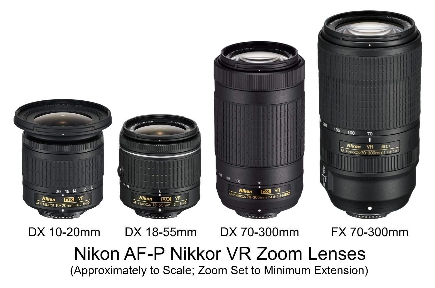
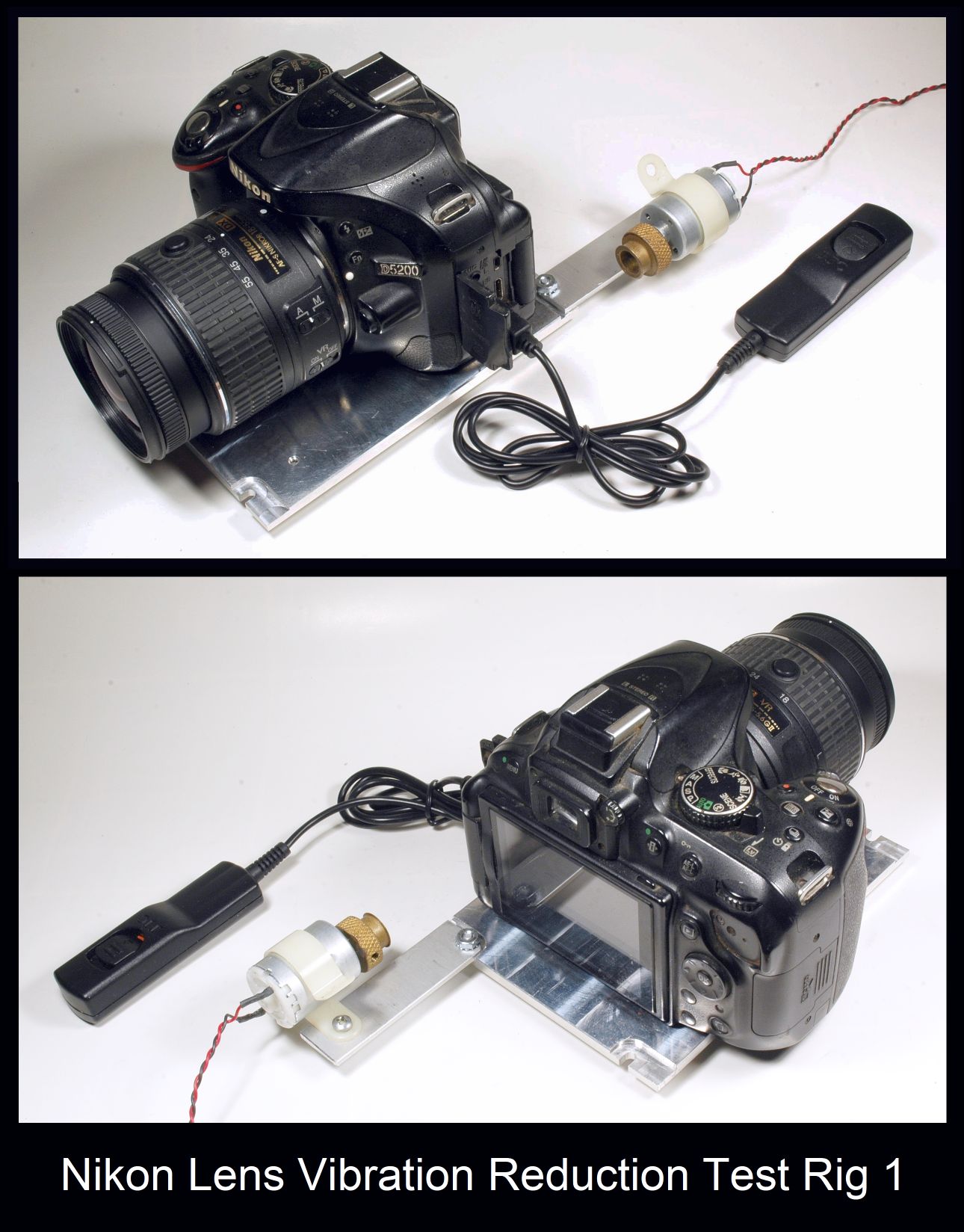
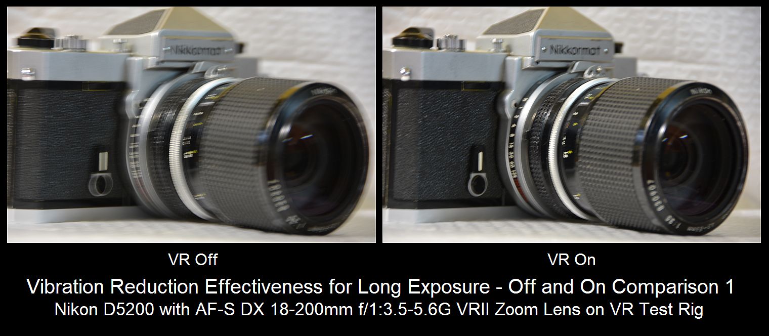
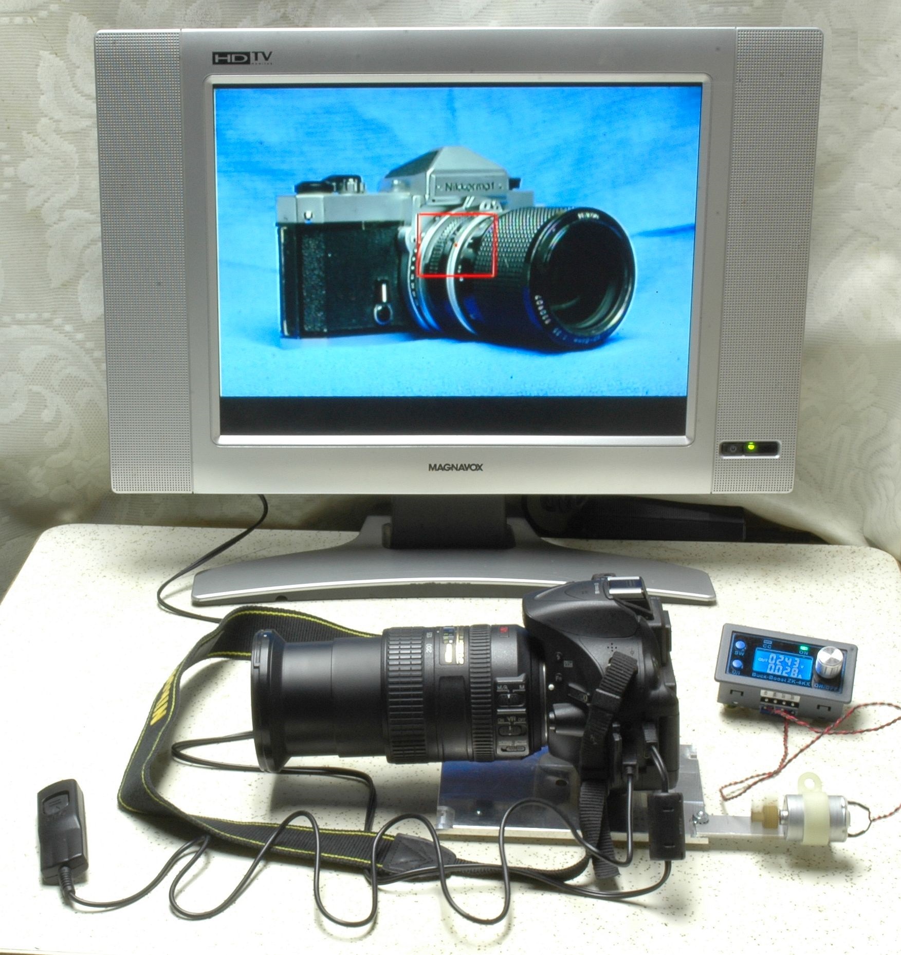
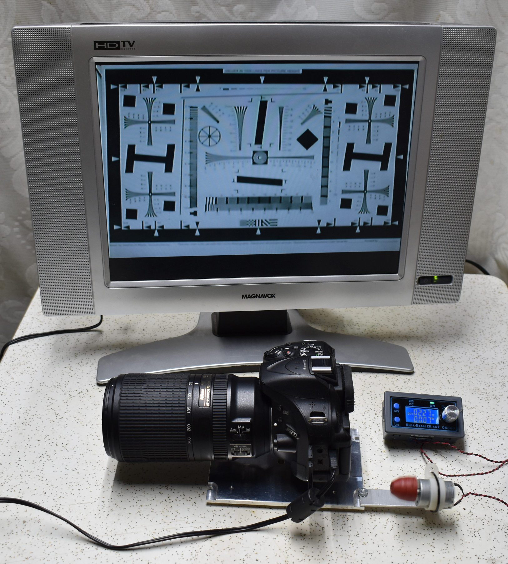
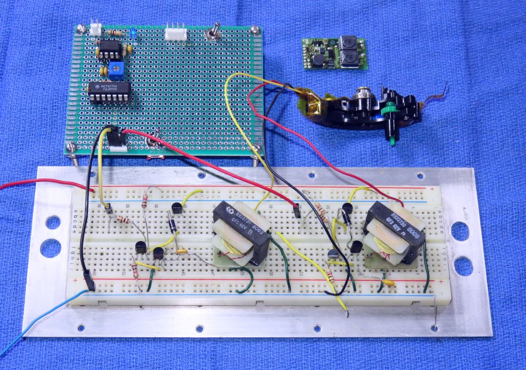
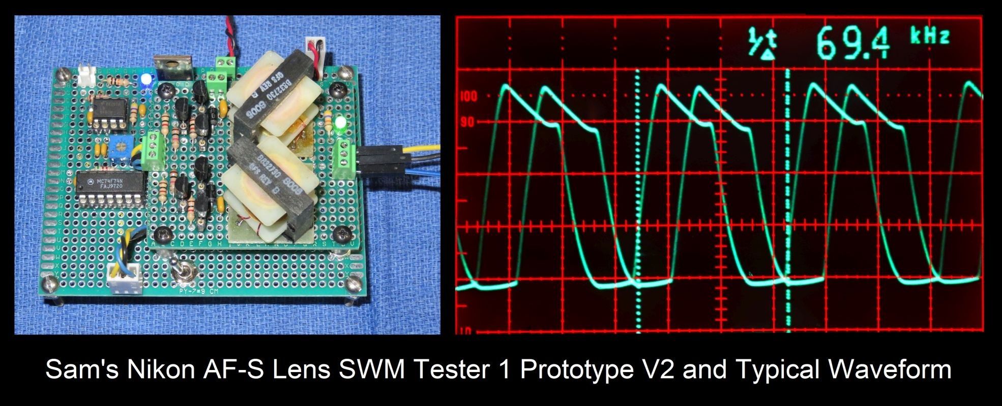
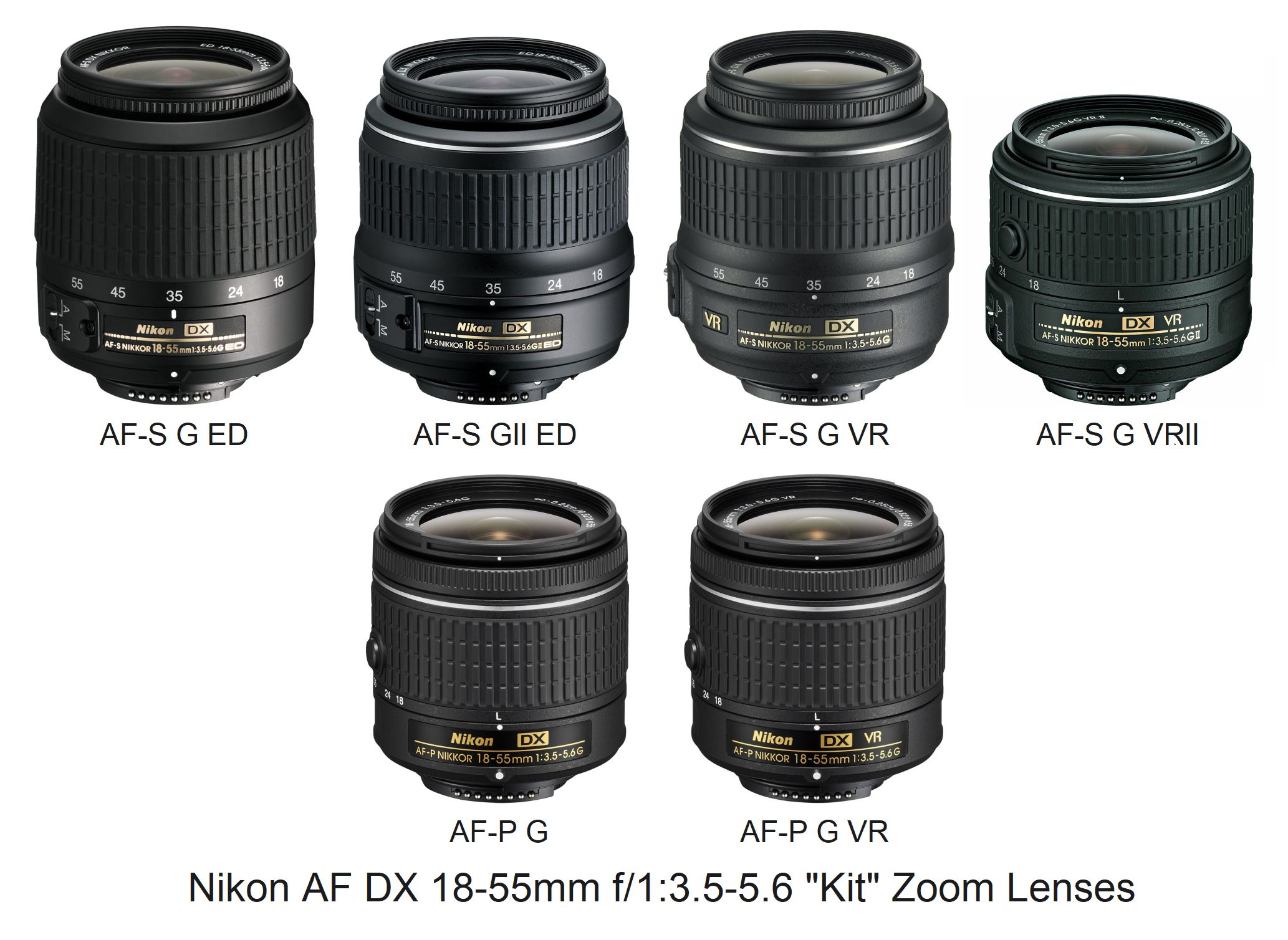
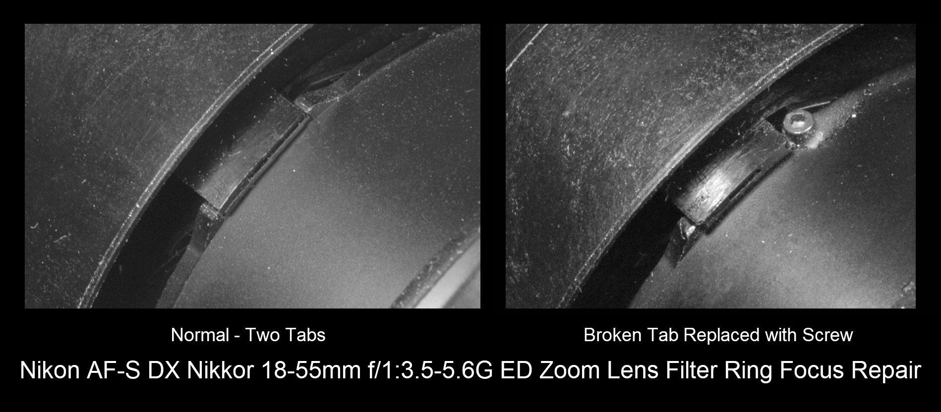
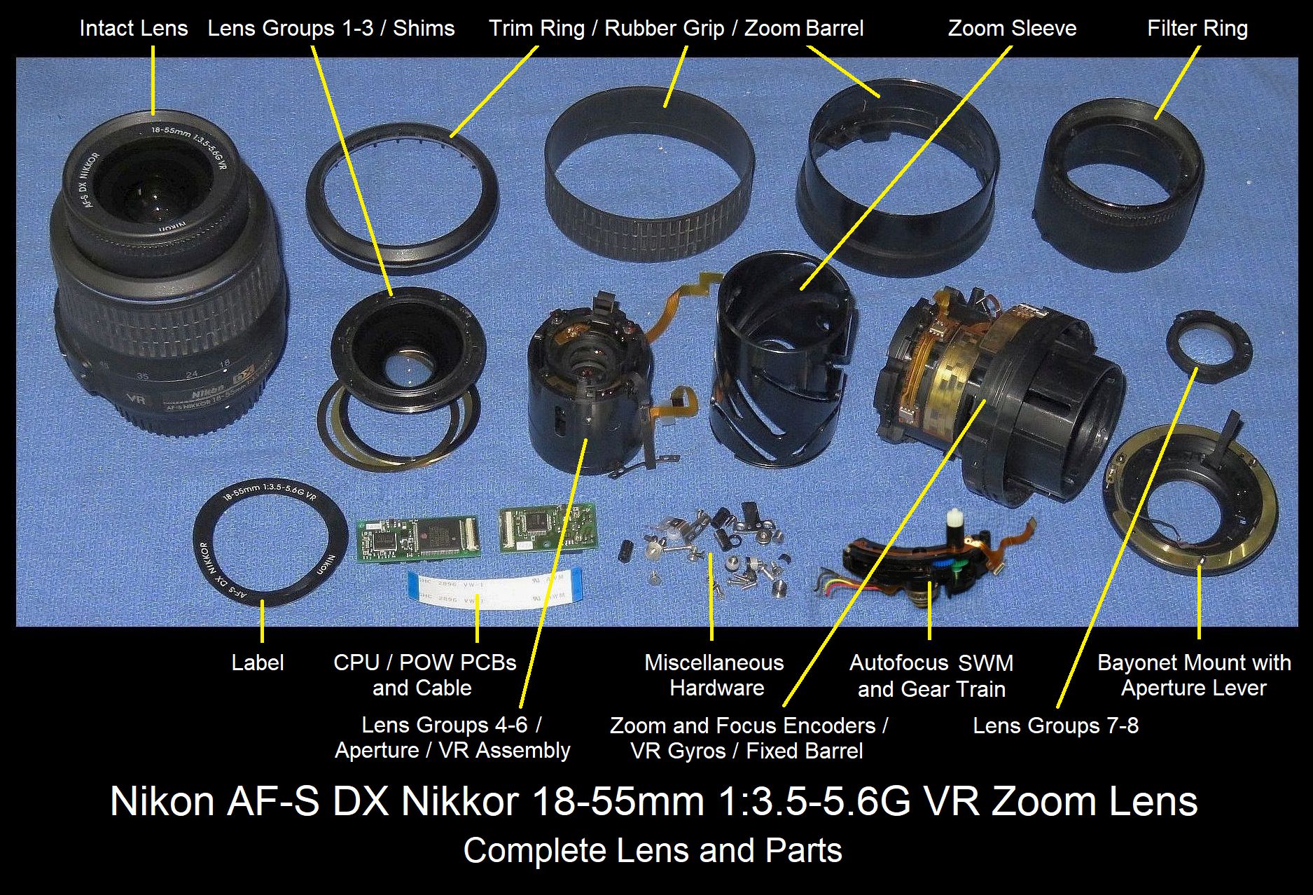
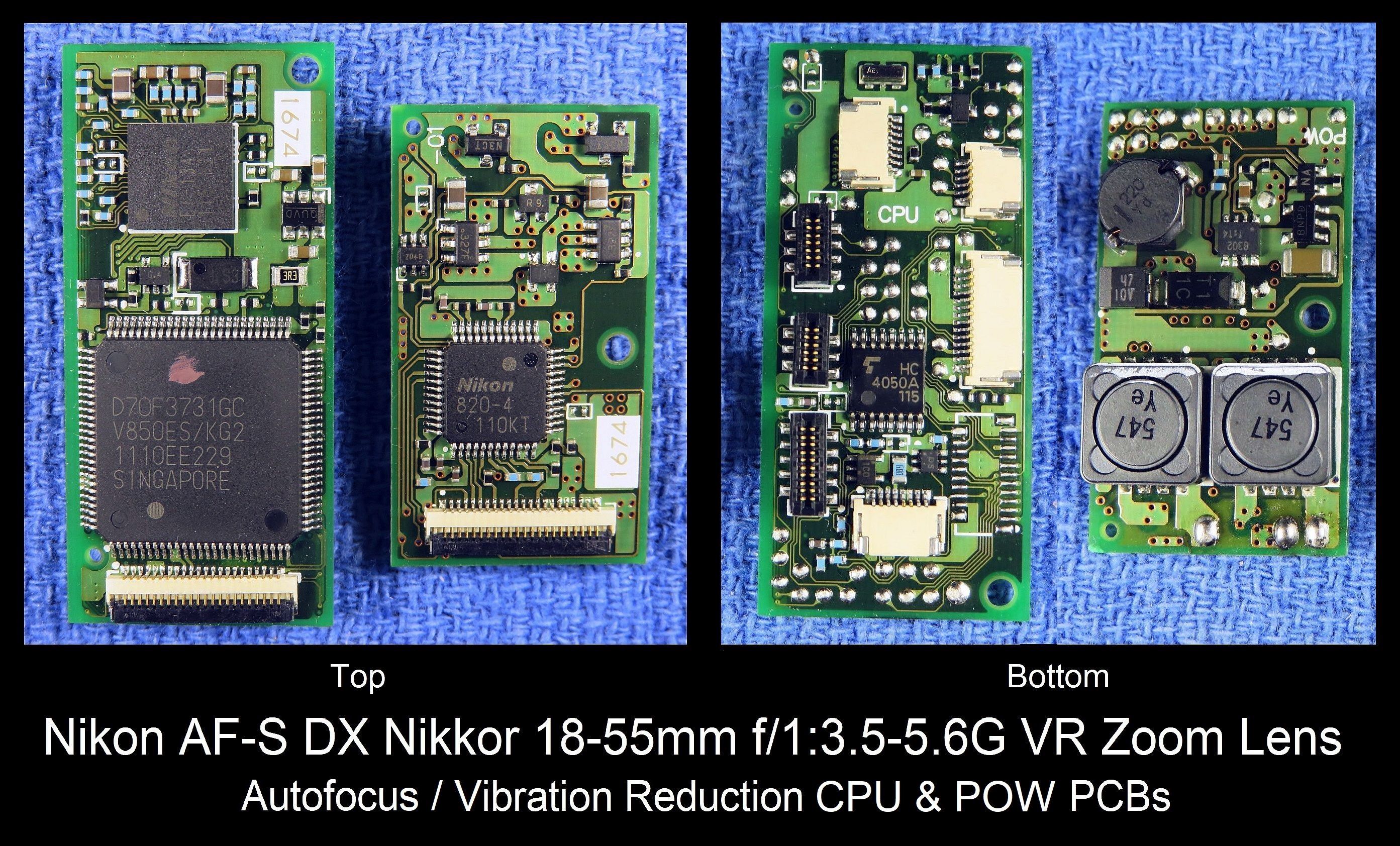
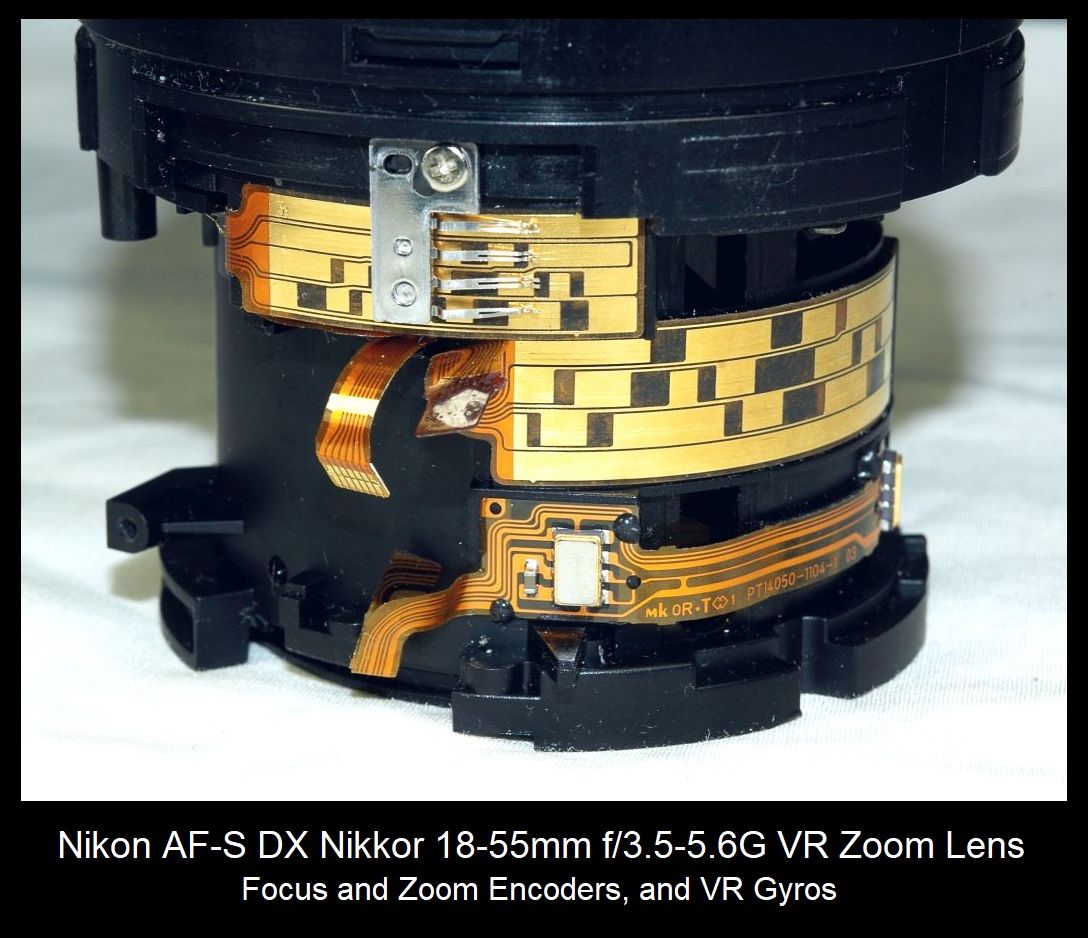
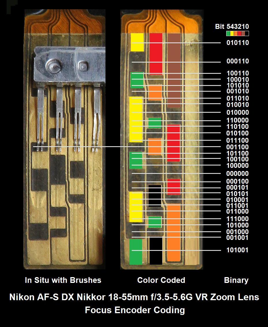
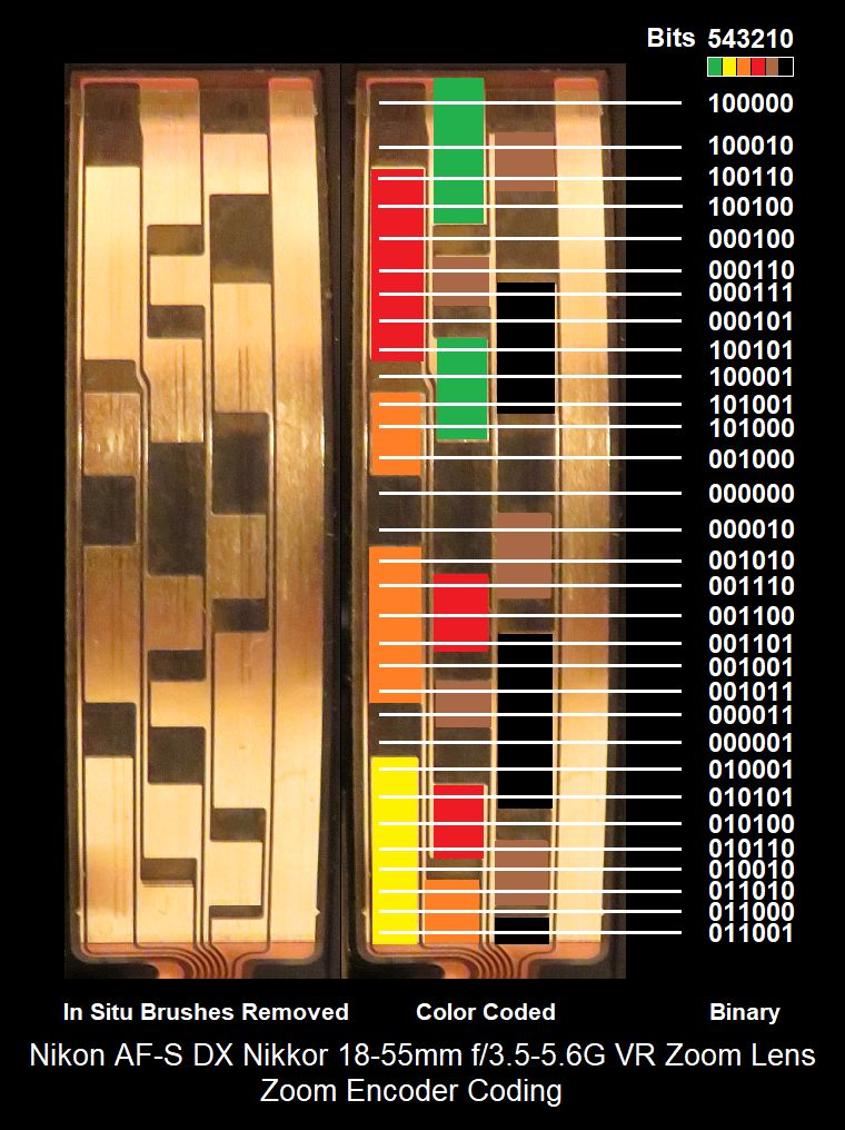
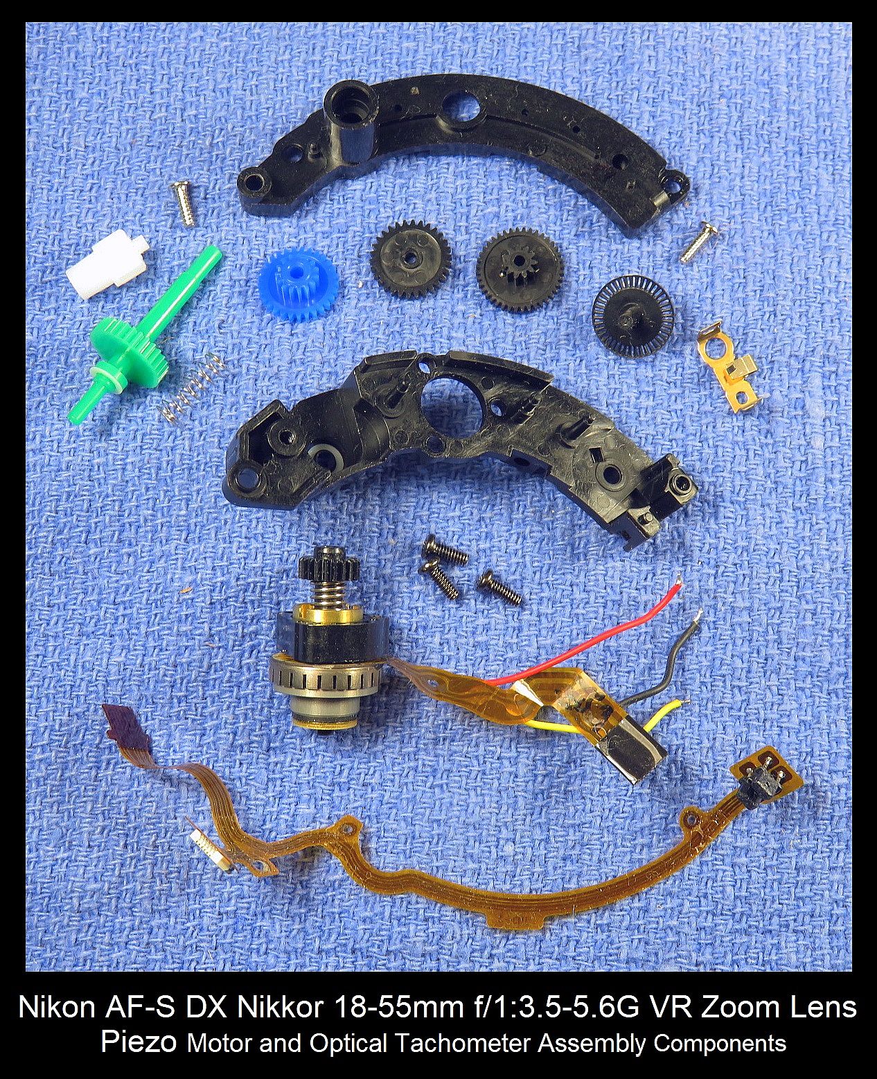
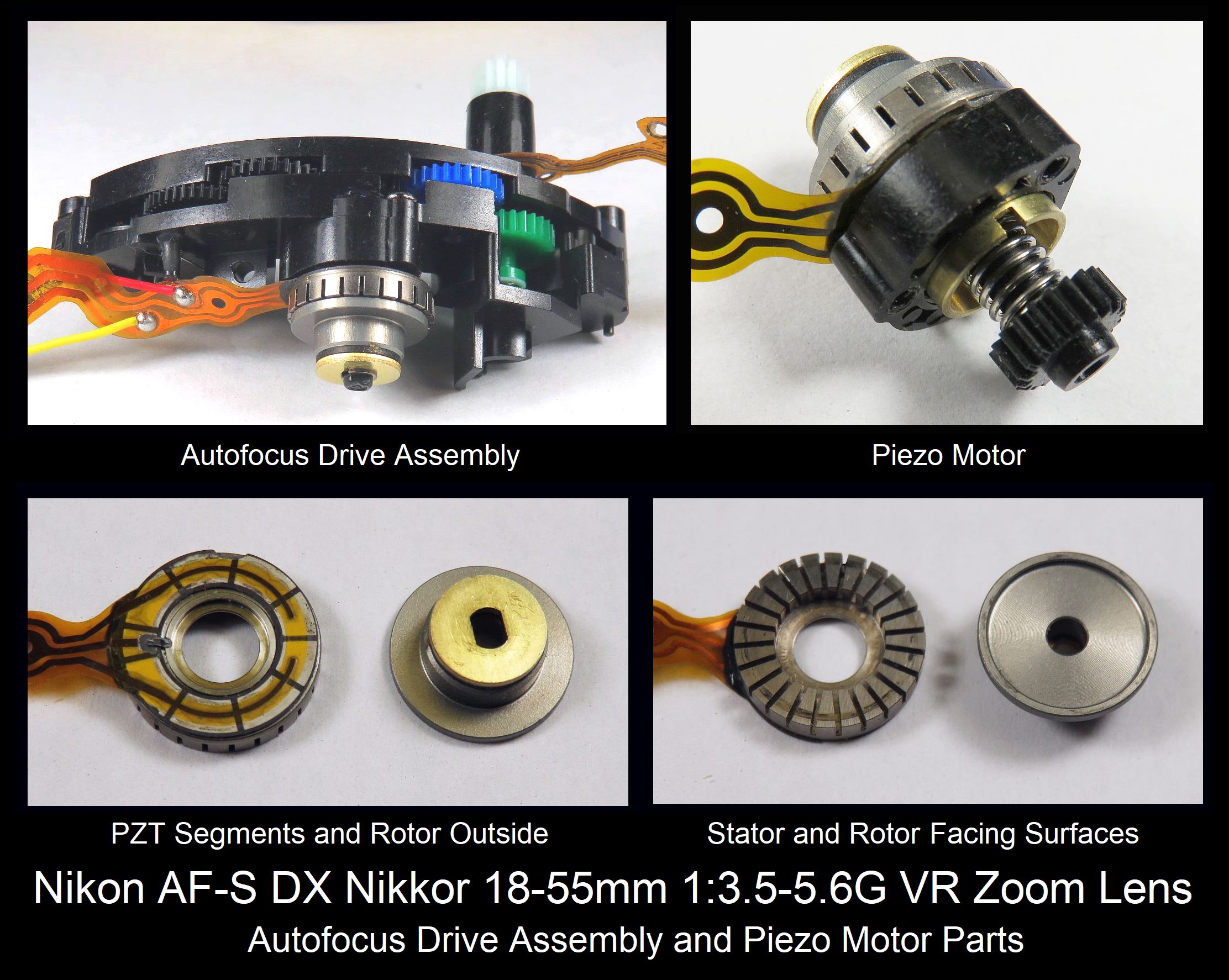
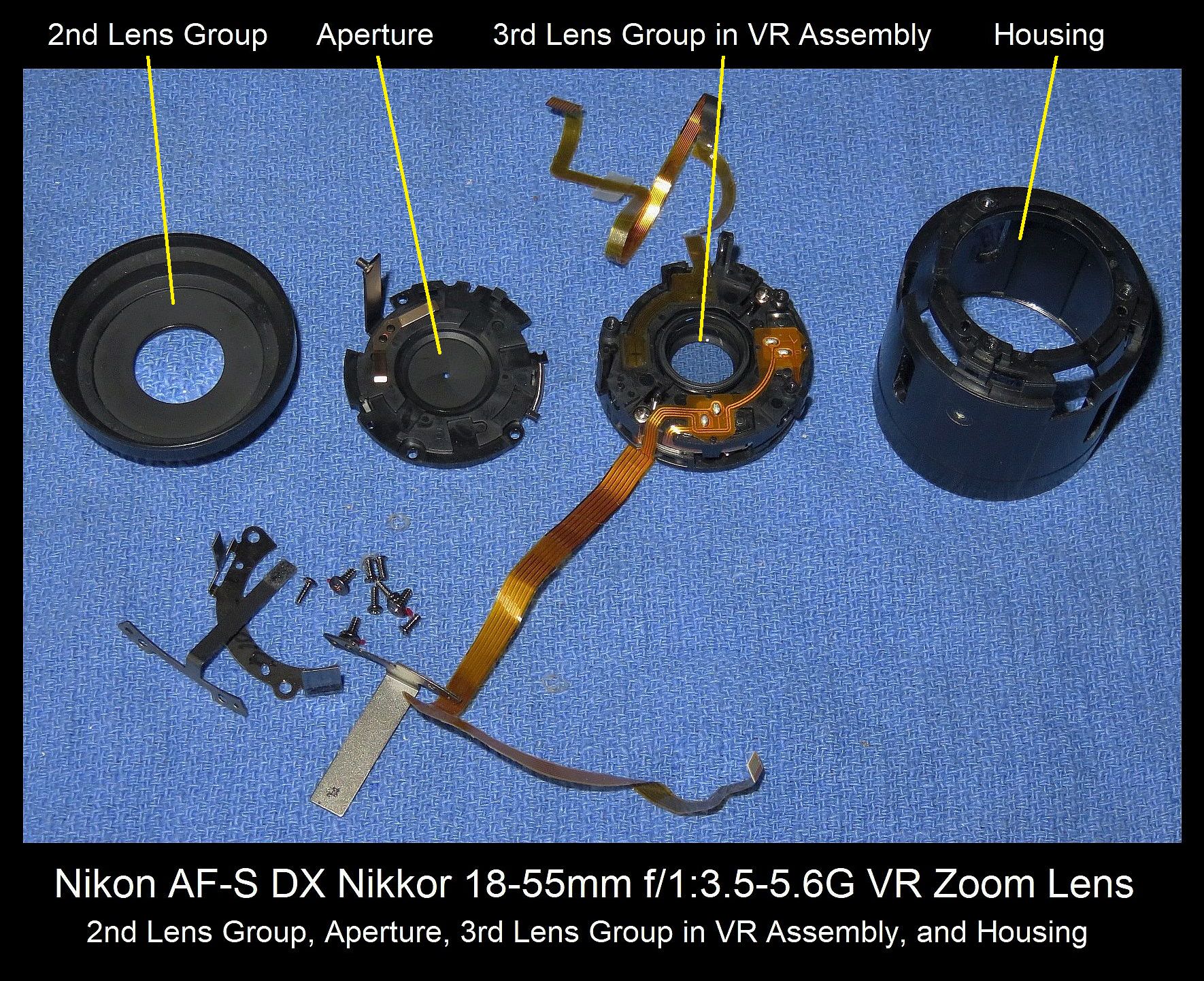
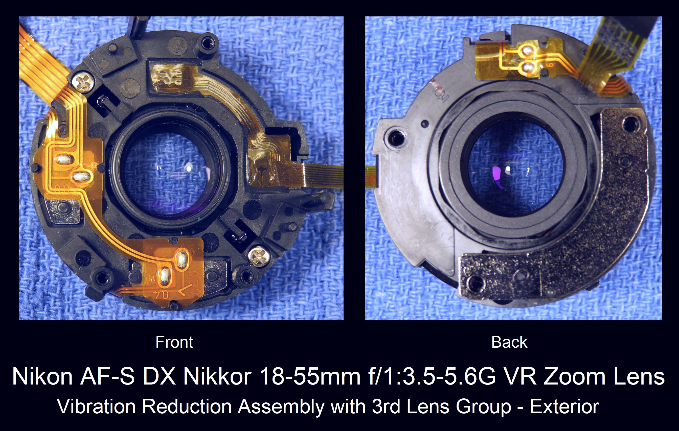
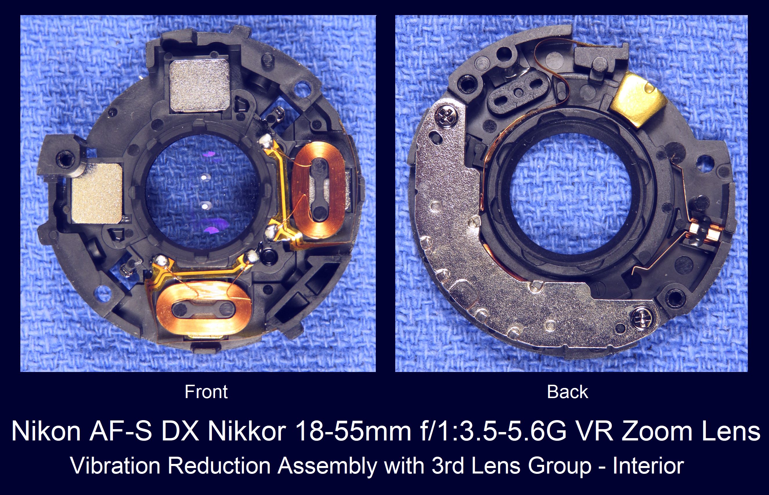
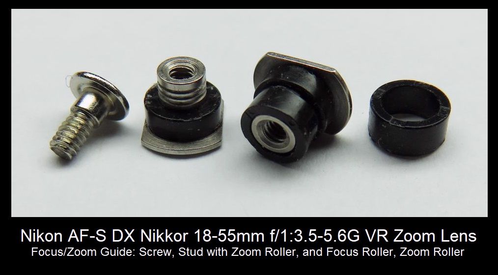
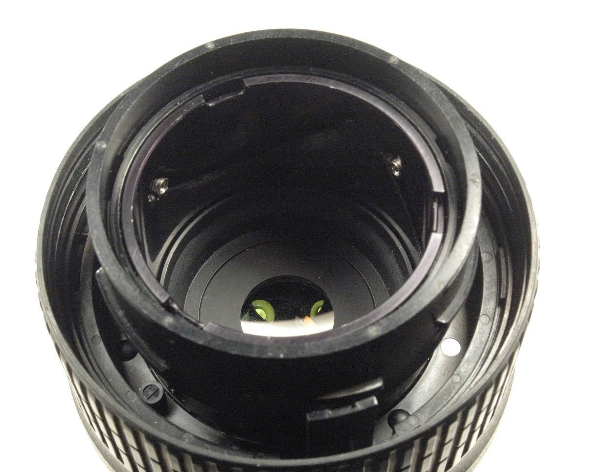
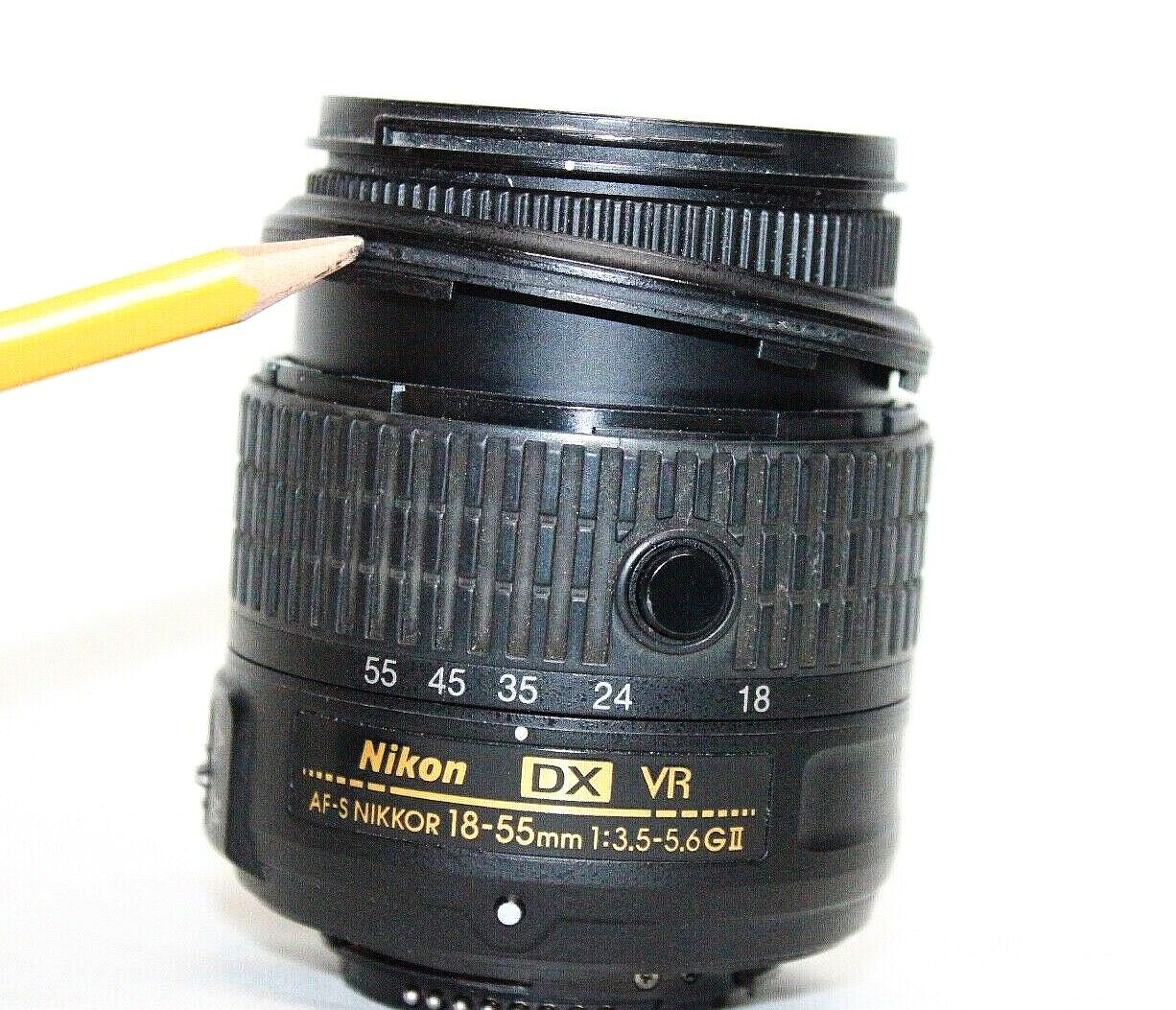
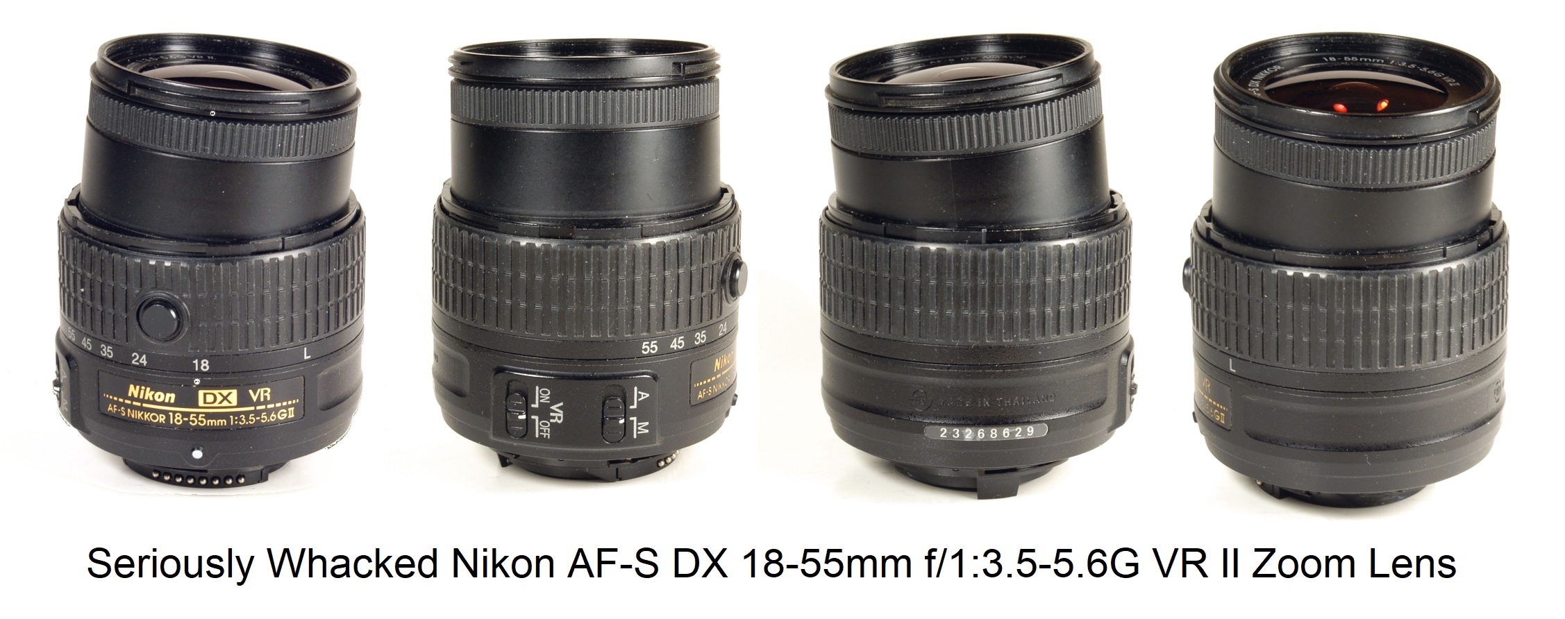
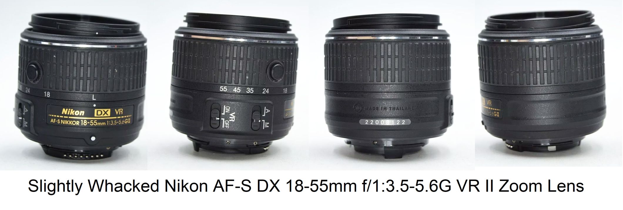
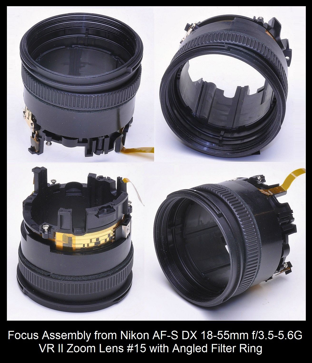
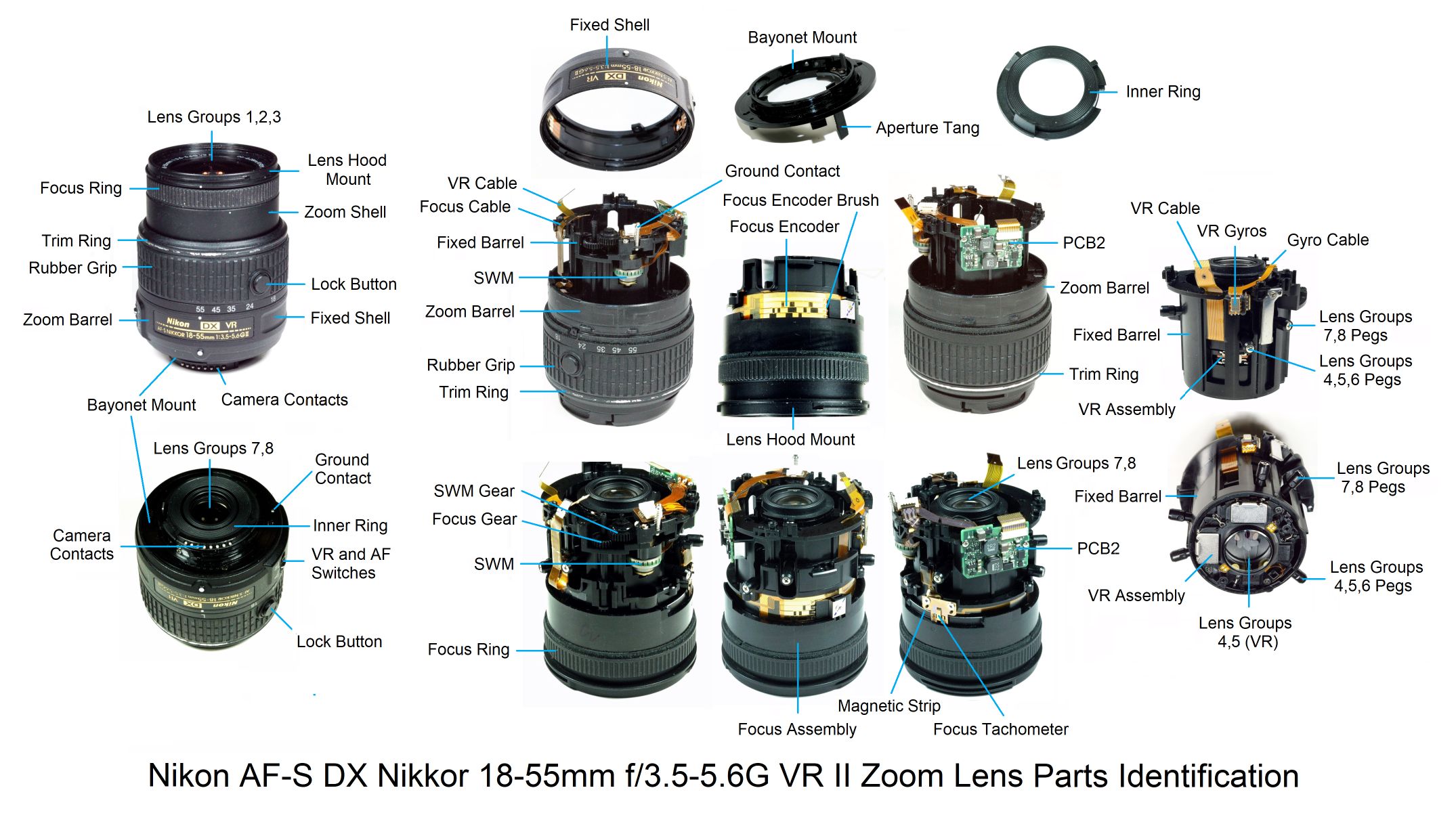
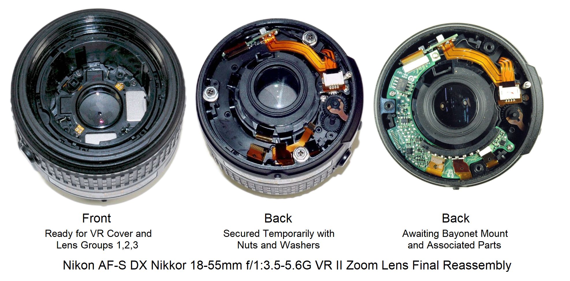
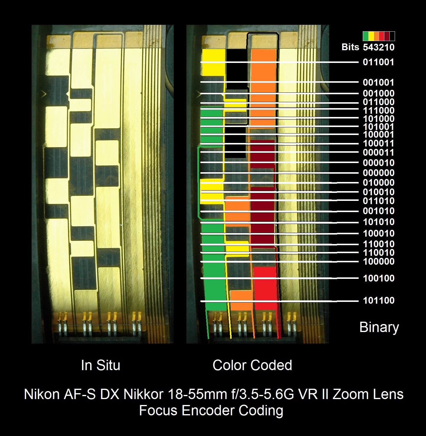
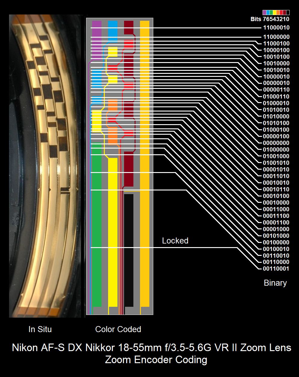
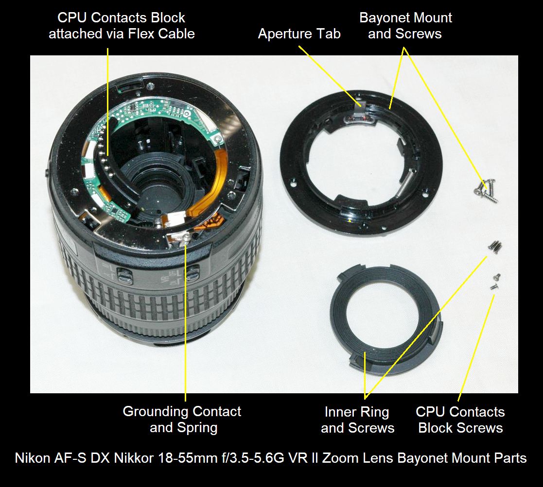
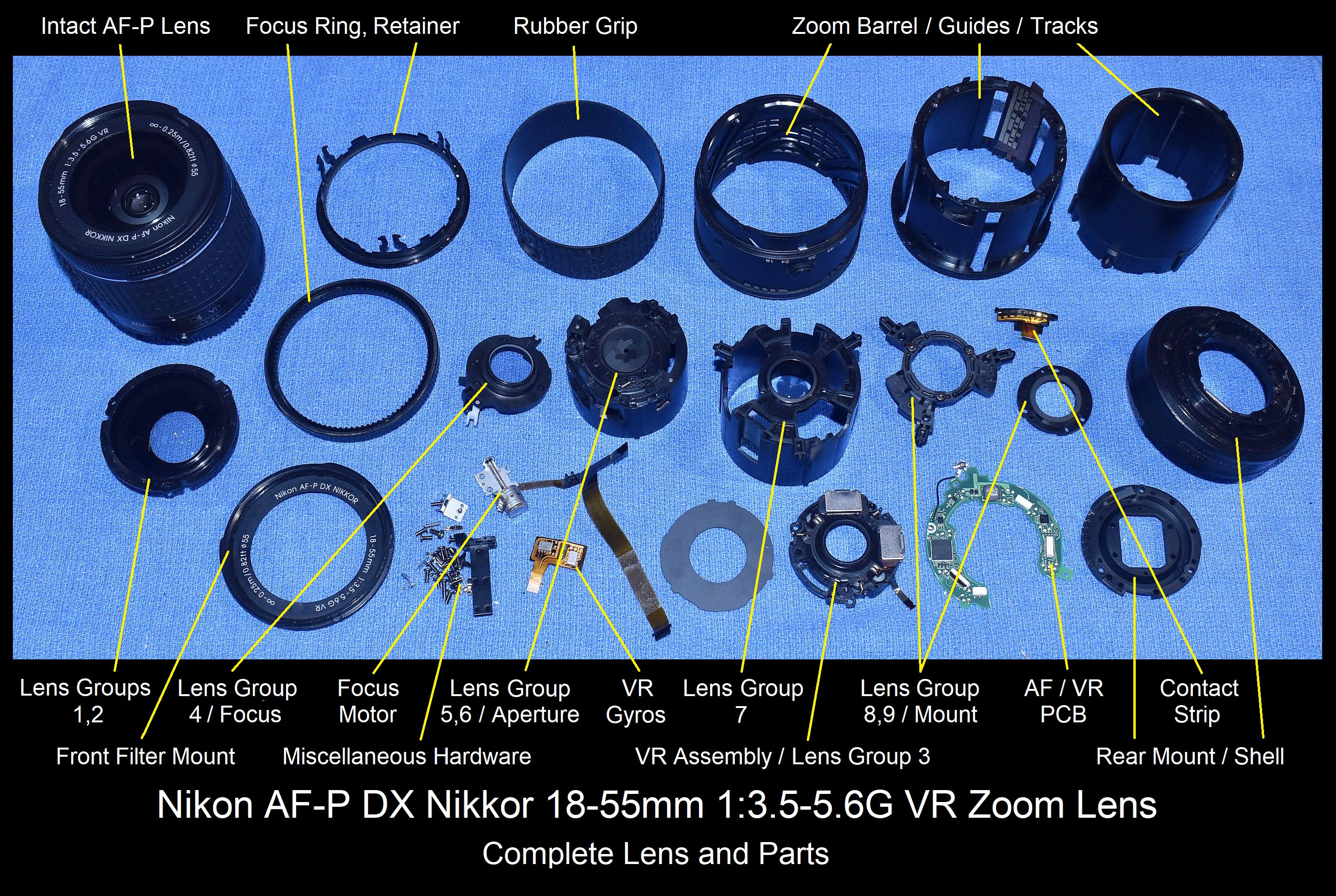
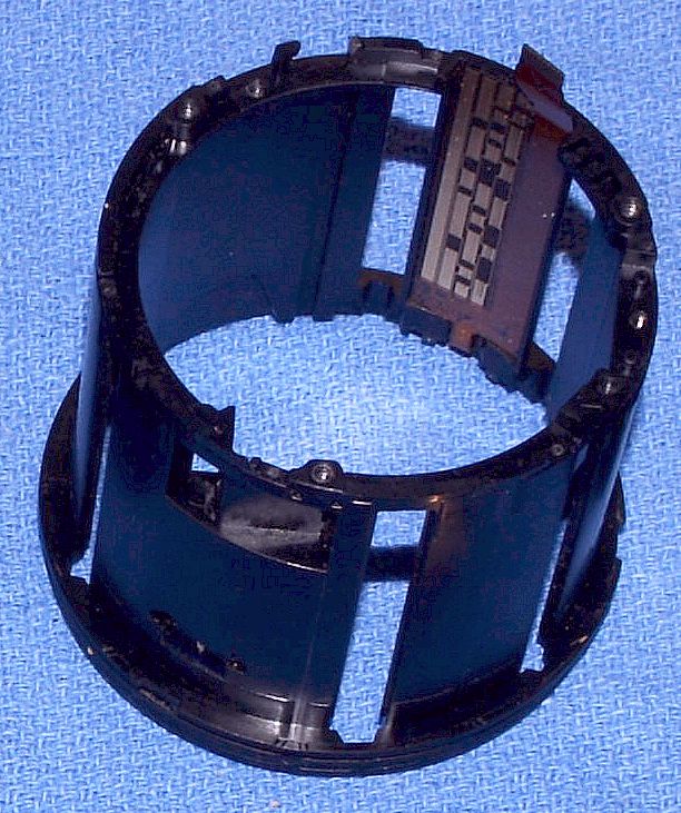
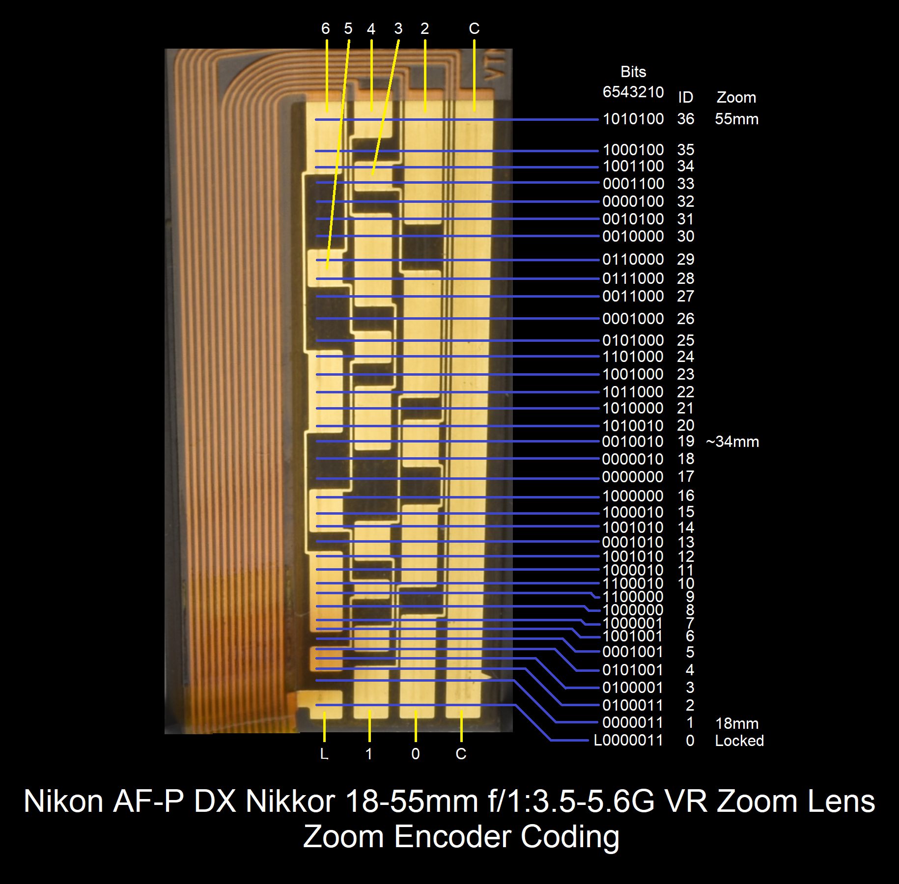
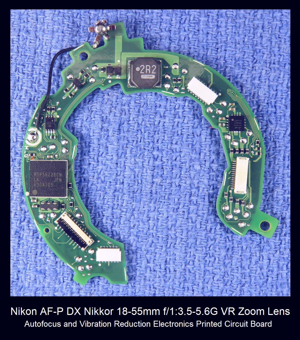
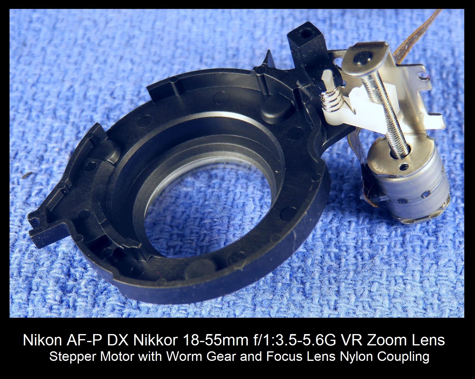
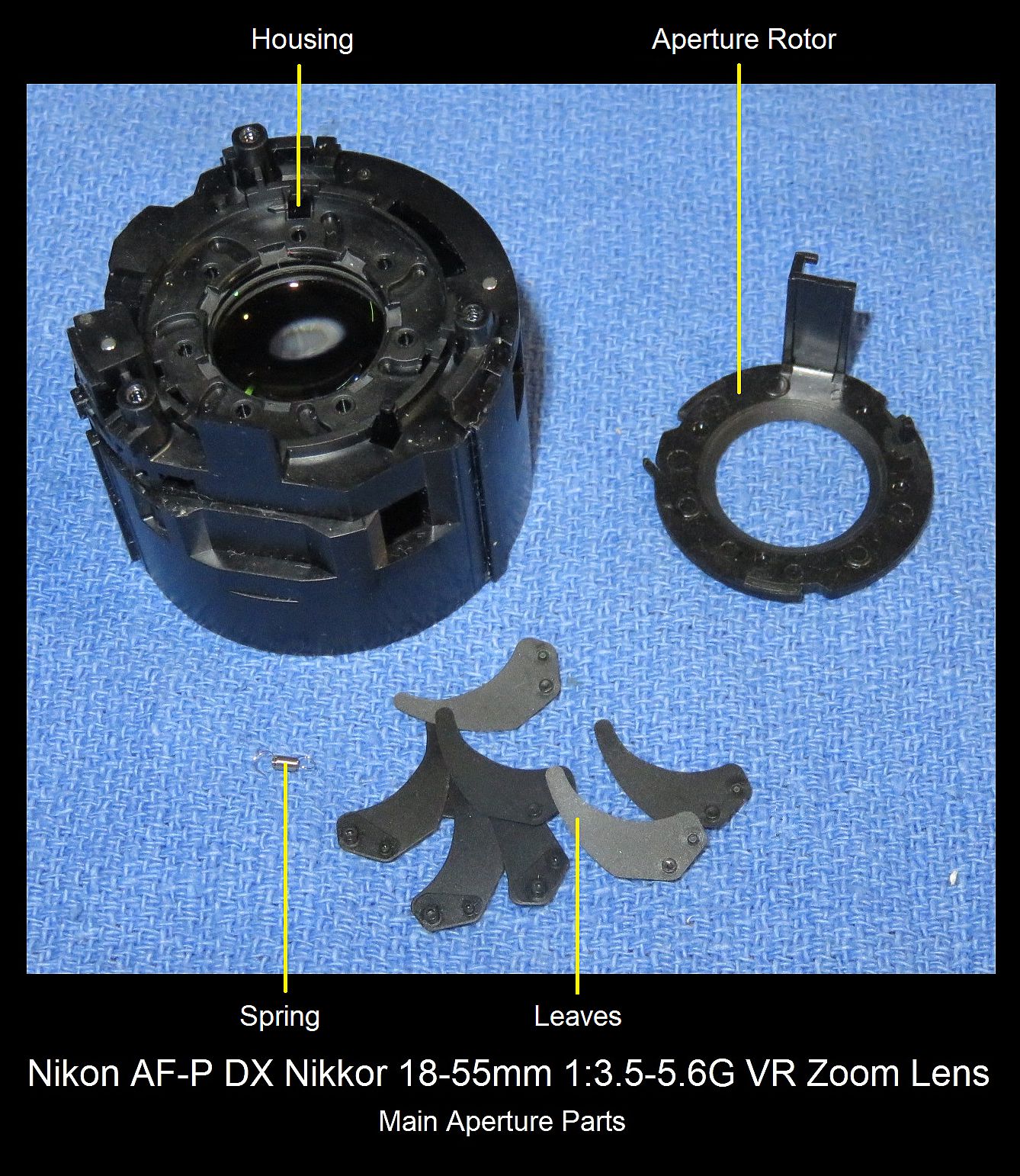
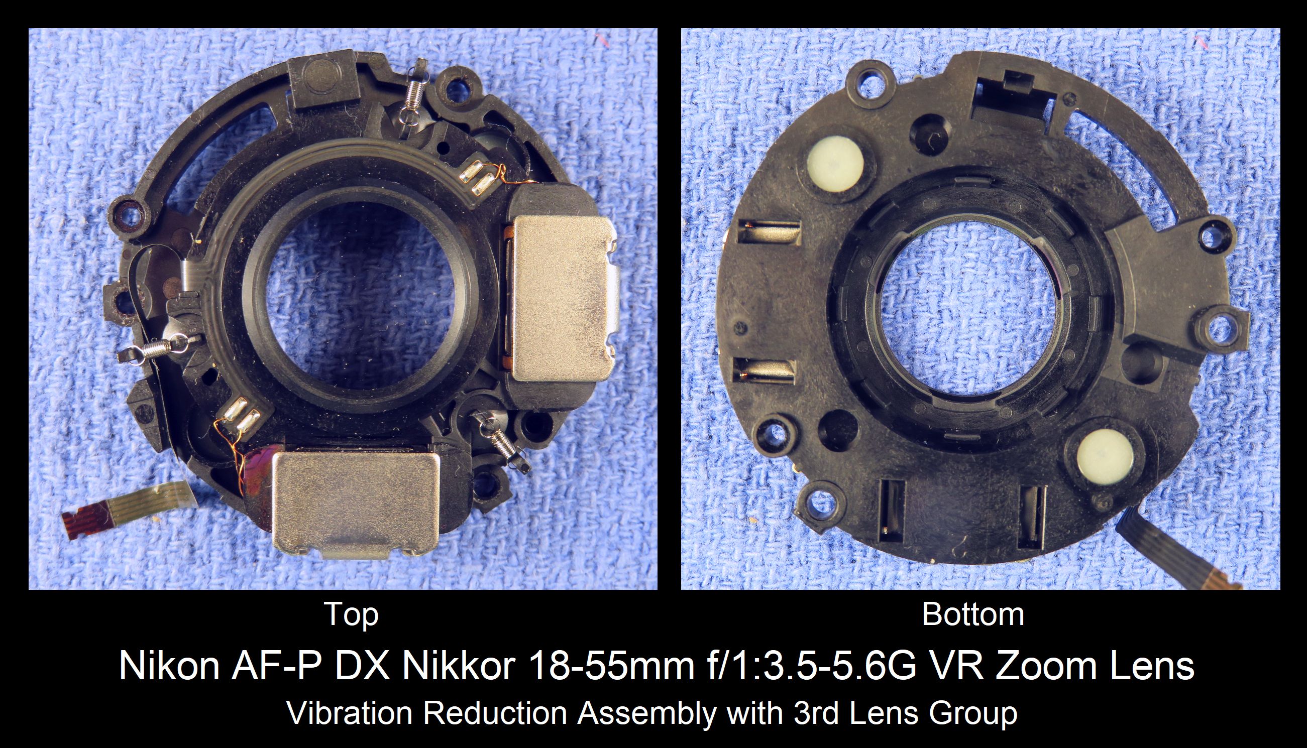
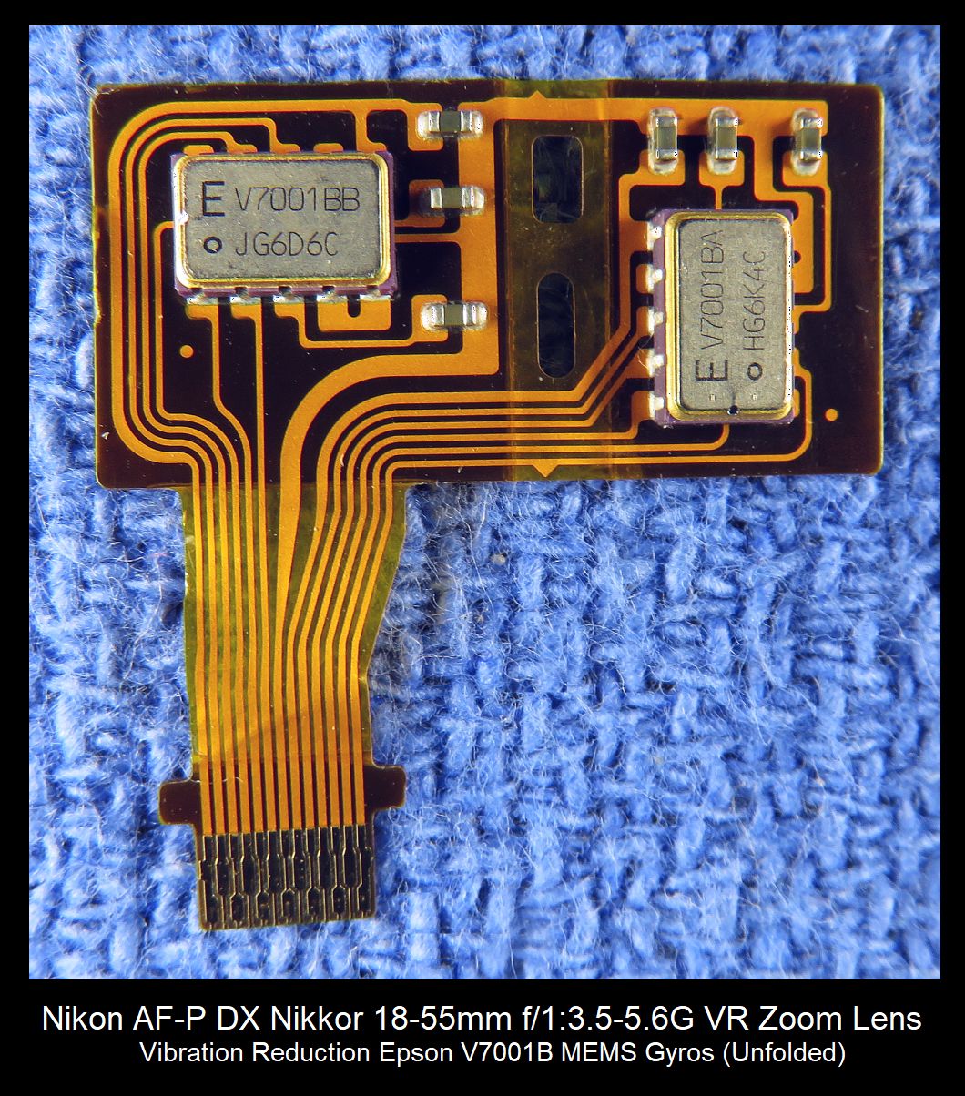
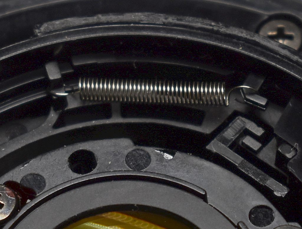
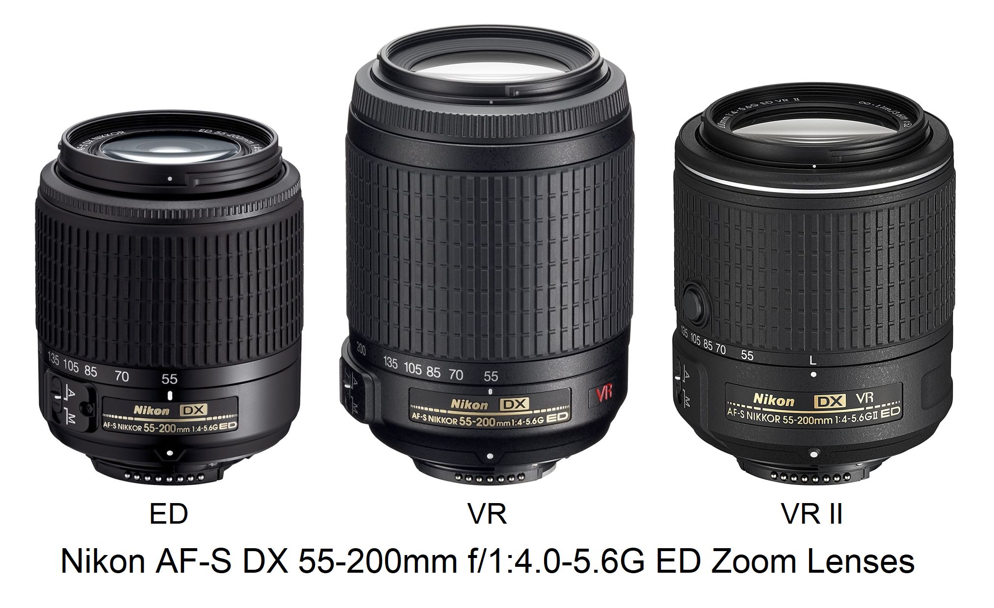
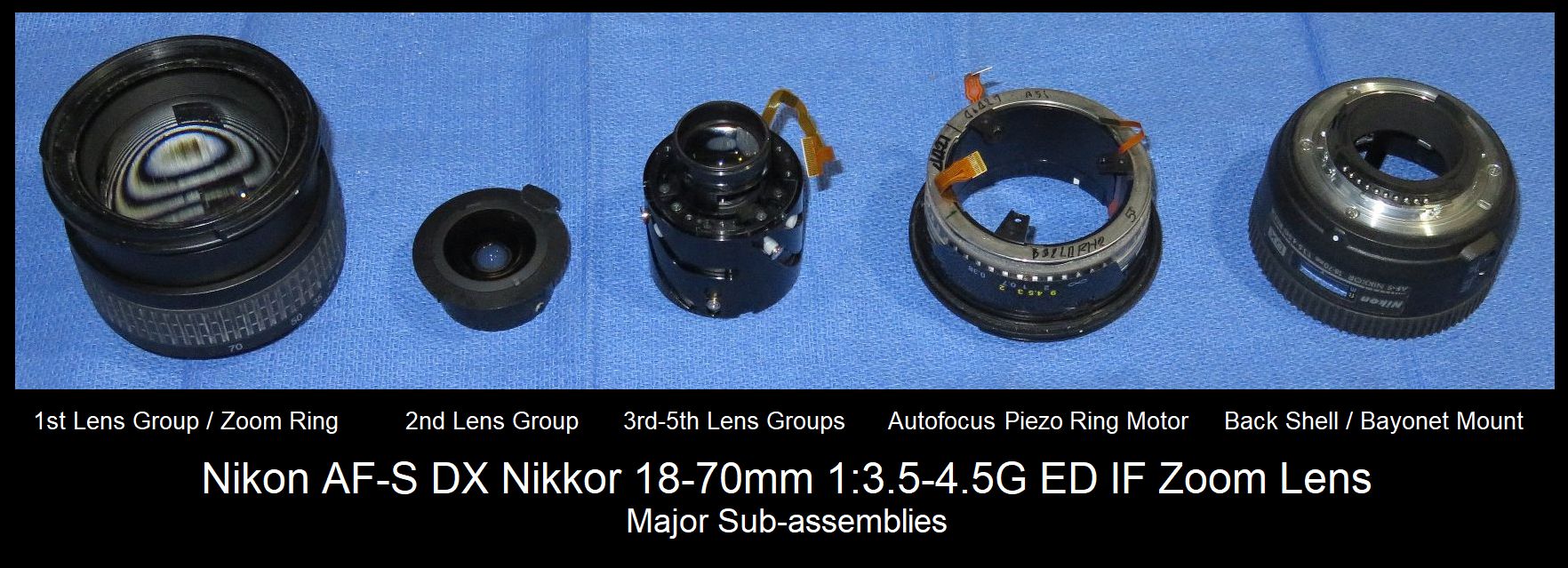
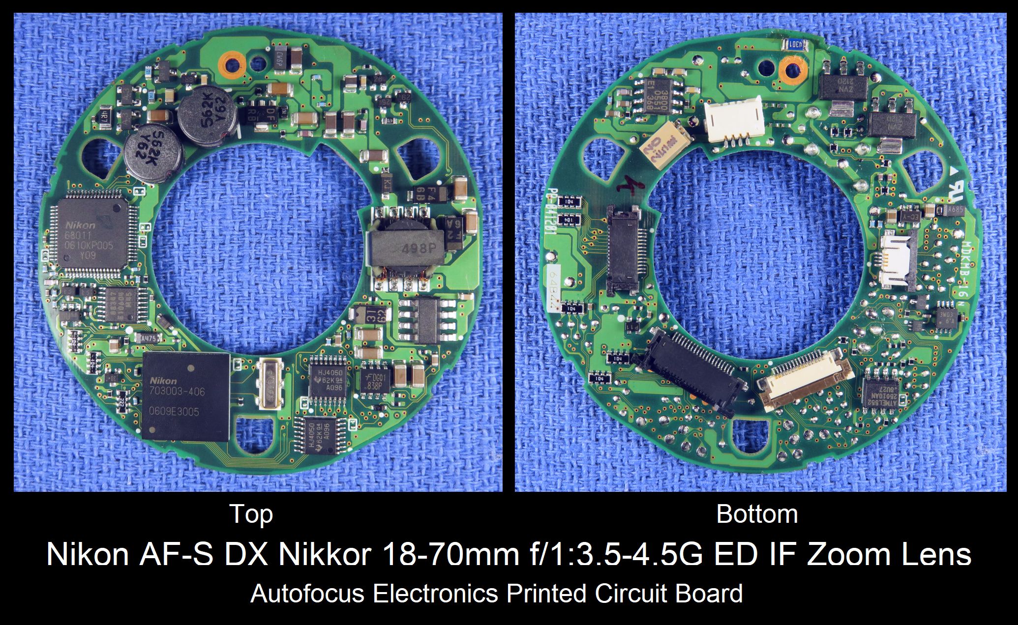
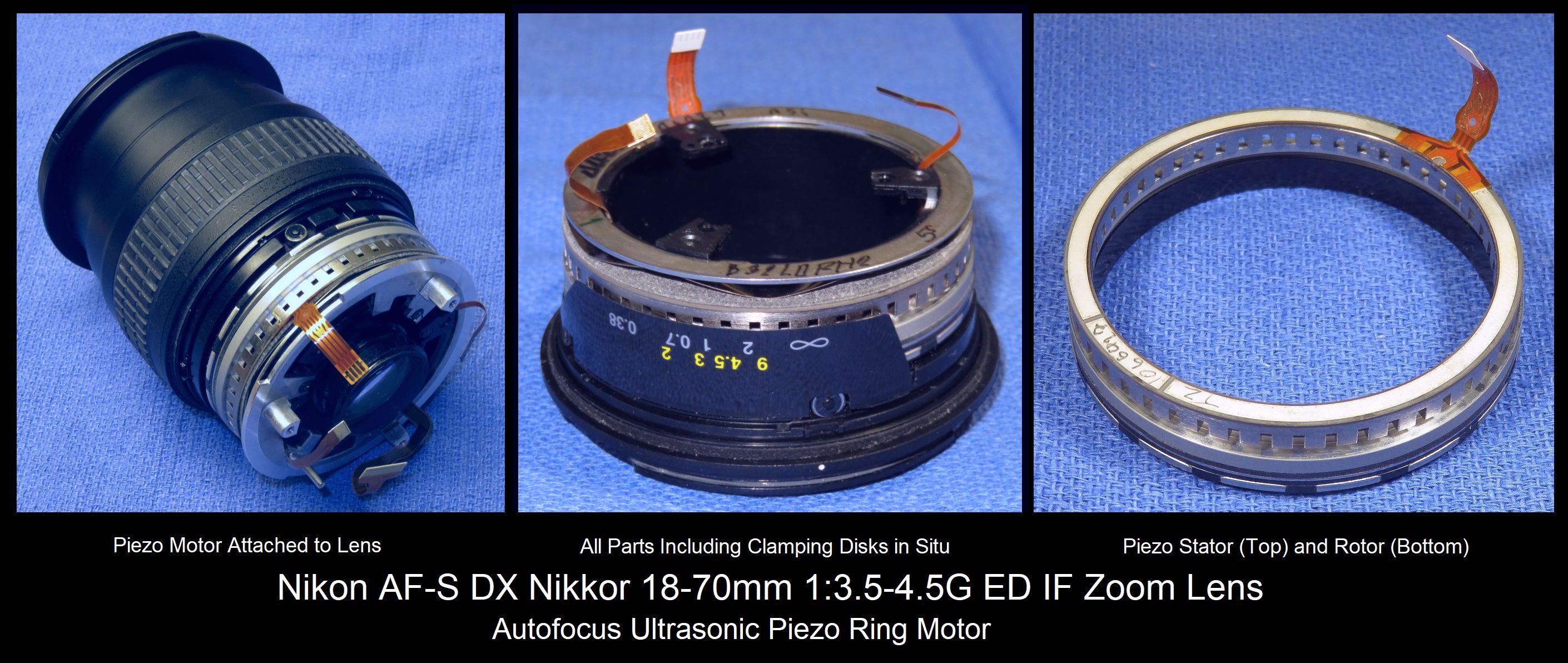
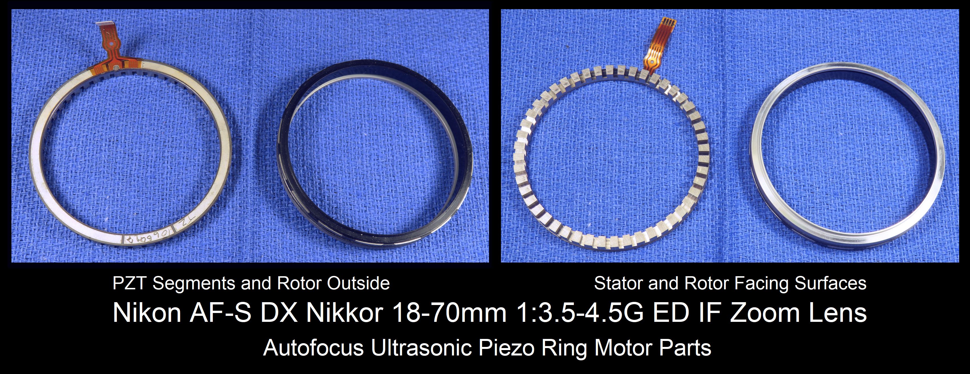
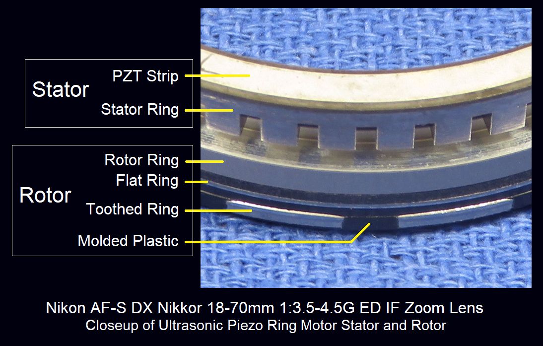
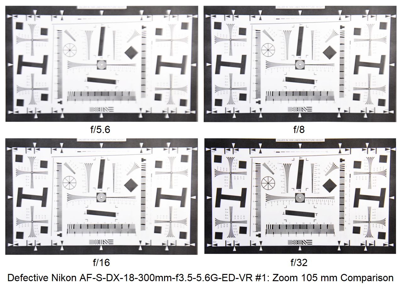
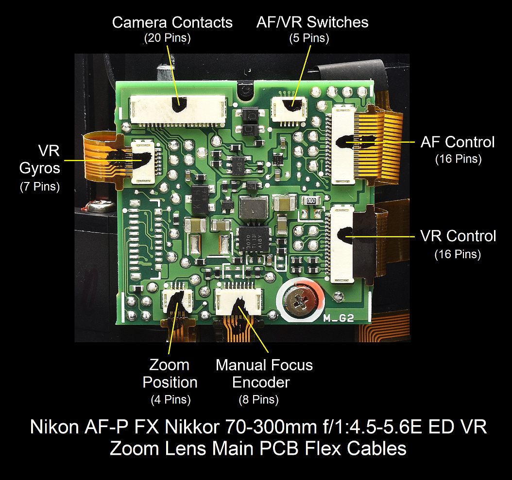
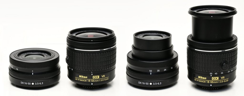
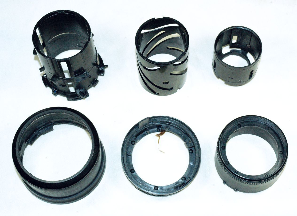
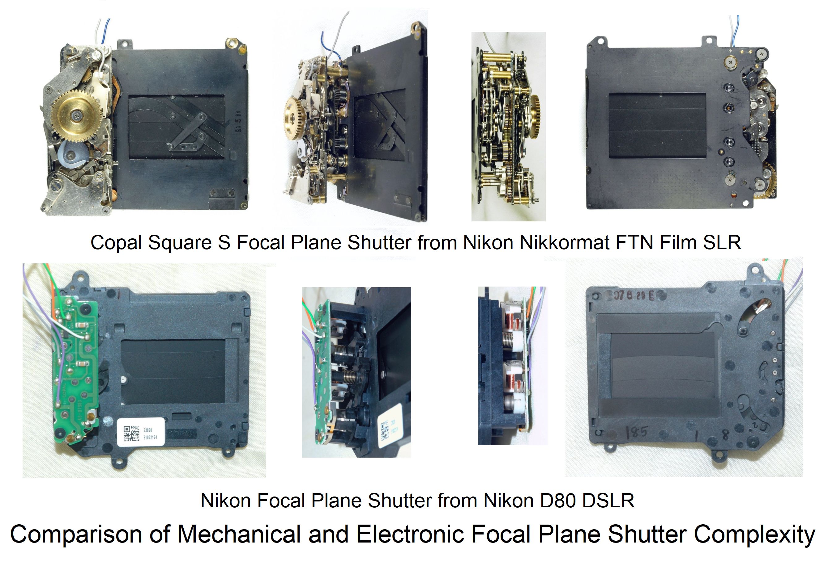