In conjunction with the other chapters on Ar/Kr ion lasers, these sets of schematics can be useful for understanding the principles of operation of ion laser power supplies or for repair of a broken unit. While what are presented here aren't really complete plans, with a bit of effort, they can be adapted to a variety of ion laser tubes to provide any degree of performance and sophistication desired - from basic and simple to full featured with all sorts of bells and whistles.
Brief descriptions are also provided of the Lexel-95 PSU, Spectra-Physics 265 exciter with a 165-3 argon head, and a few other systems. Schematics for these may be added in the future.
See the Laser Equipment Gallery for for multiple detailed photos of several argon/krypton ion lasers and power supplies.
Note: For an explanation of the meanings of various designations like DC+, Boost, Tube-, etc., used in these schematics, see the section: Notation used in Ar/Kr Ion Laser Power Supply Diagrams and Schematics.
  (Note 1)   (Note 2)  (Note 3)           (Note 4)
   Desig-     Power   Regulation  <---- Tube Voltage ----->
   nation     Input   Type  Mode   80 90 100 110 | 180 220     Typical Heads
 -----------------------------------------------------------------------------
  Omni-150   115 VAC    S   C/L        ********              ALC-60X/Omni-532
  NEC PSU    115 VAC    S   C/L      ********                  NEC GLG3030
  SP-261     115 VAC    S   C/L        **********                 SP-162
  Lexel-88   230 VAC    L   C/L                    *******       Lexel-88

  SG-IT1     115 VAC    N   NA       ***********                 (Note 5)
  SG-IX1     115 VAC    N   NA       ***********                    "
  SG-IY1     115 VAC    L    C       ***********                    "
  SG-IL1     115 VAC    L   C/L      ***********                    "
  FS-IT1     230 VAC    N   NA       ***********                    "
Notes:
Suitable transformers are not terribly expensive to buy new but can also be found in salvage yards associated with equipment like photocopiers.
Running a three-phase power supply on single-phase power entails additional problems since (as is shown below), much less filter capacitance - if any - is required using three-phase so the entire front end would have to be rebuilt to achieve adequate performance.
Laser manufacturers may also have connection diagrams for their systems. One example is:
One thing that may not be present when acquiring a laser head and power supply separately is the umbilical cable. These are very expensive if purchased new (assuming this is even possible anymore). However, they do turn up from various surplus places and on eBay, sometimes at more reasonable prices. And, if you're handy with a soldering iron, they can be built for under $50 from readily available components. The following applies directly to the cable having identical round connectors at both ends such as on the ALC-60X/Omni-532/543 but it should be possible to construct others as well. See the specific sections on the interconnect wiring for these lasers to determine minimum wire sizes for the high current conductors (filament and anode).
The connectors and pins for making a cable are AMP parts available on-line from Digikey. The cost of making a cable would be about $50. All the connections in the umbilical run 1 for 1 straight through, i.e., pin 1 is pin 1 at both ends.
You need 4 of the big female filament pins at about $7 each and two end shells at about $6 each and a bag of the smaller pins at about $15. You'll also need the mating remote connector body, about $6 also. Here are the part numbers for making the ALC-60X/Omni-532/543/etc. umbilical cable:
Shell: AMP type 206613, Series 4 CPC (Circular Plastic Connector) Size/contact arrangement 23-22M, standard sex-free hanging plug.
Pins:
These can be obtained from the major electronics distributors like Digikey, Mouser, Allied, etc.
Regardless of the connector types, if building your own umbilical, or an extension cable, there are usually only 3 wires that are critical for current: the filament (usually called F1 and F2) and DC+ (the anode connection). To be safe, use two #10 AWG (or one #8 AWG) wire for F1 and F2, and one #10 AWG wire for DC+. Yes, #10. It's not only a matter of safety as would be the case in house wiring, it's the voltage drop. F1 and F2 have 20 to 30 A on them for the filament current as well as the return current from DC+ (up to 10 A or more). And the voltage across the filament is only 3 VAC.
Everything else is usually low current, so #22 AWG wire should be fine (but fatter won't hurt). Use twisted pairs for light feedback or other low level control signals (twisted with signal ground).
There are also various types of information on other ion lasers systems that aren't nearly as complete but should be useful when attempting to get a laser operational or to repair one without complete manuals or documentation. This includes some laser head diagrams and interconnect wiring descriptions for several systems. Also see the section: Specifications and Pinouts for Various Argon Ion Lasers.
The Omnichrome 532 and American Laser Corporation 60X are functionally very similar (possibly identical for some versions). With the ALC-60X/Omni-532 being the most common argon ion lasers available surplus to the hobbyist, experimenter, or budding light show enthusiast, having a detailed schematic is a definite plus (what an understatement, huh?!). These circuit diagrams can also serve as the basis for a simple switchmode power supply design of your own! The Omni-150R can drive a variety of small Ar/Kr ion tubes requiring up to 10 A or so continuous current at 95 to 110 VDC - which covers most of the types of air-cooled tubes you are most likely to acquire. This would include the ALC-60X/Omni-532, Cyonics/Uniphase 2214 series, and many Spectra-Physics models. I expect that it can also power the NEC GLG3030 and other tubes requiring as little as 80 VDC (possibly limited to slightly less maximum current) but have no hard information on reliability when operating under these conditions. See the section: Running Ion Tubes with Lower DC Voltage Ratings on the Omni-150.
The Omni-150P is another version of this power supply with essentially the same specifications. It has a different PCB layout and there were a few modifications including the use of a commercial current sense transformer instead of the custom one used on the Omni-150R but it is nearly identical electrically. And, the MWK Laser Products model MWK-APS appears to be a virtual clone of the Omni-150 designs with only some minor simplifications (like the elimination of multiple taps on the filament transformer). Even most of the part numbers are identical. (I know that a complete schematics/parts list/PCB layout package for MWK-APS is available from MWK Laser Products but I don't know if they offer an assembled version.) Therefore, the Omni-150R schematics and descriptions that follow should be quite useful in troubleshooting either of these units.
The Laser Equipment Gallery has detailed views of various argon/krypton ion lasers including examples of the very popular 60 series from American Laser Corporation. However, note that the ALC and Omni models are plug compatible, the ALC power supply is NOT electrically or physically the same as the Omni-150R described below.
The diagrams are available in PDF format. There are three (3) separate sheets:
Due to some inconsistencies between the '150R' and '532' schematics that I used, some signal names and/or connectors identification may not match. I have attempted to correct these discrepancies where possible. However, this may have resulted in using names that were different than the 'official' ones in some cases.
Note that ALC's own power supplies are entirely different electrically from those from Omni. Only the heads and electrical interfaces are identical as per Xerox standards. Thus, these schematics (150/155) do not at all apply to an similar American product. Newer supplies have RS232 controls options and are power factor corrected.
The basic operation of the each of the major functional blocks are summarized below. For a more detailed discussion of the operation of the individual circuits, see the chapter: Ar/Kr Ion Laser Power Supplies.
RLY1 also enables the power supply fan and the igniter circuitry. (The fan in the laser head runs as long as SW2 is in the ON position.)
WARNING: For these line connected designs with a bridge rectifier, NO part of the circuit can be tied to earth ground (as is possible with a HeNe supply) for safety. Therefore, troubleshooting must be done with extreme care especially if no isolation transformer is used. Connecting the ground lead of a properly grounded scope to any part of the circuit will result in smoke or worse!
WARNING: ALL the power and some of the associated control circuitry is line-connected.
(From: Darren Freeman (daz111@rsphy1.anu.edu.au).)
The MOSFETS switch from DC+ to DC- (the full voltage across the main filter capacitor bank), so the voltage of the load is irrelevant. Whenever the freewheeling diode (D20 on the schematic) is conducting, the MOSFETs see the input voltage. And the average current through the MOSFETs isn't the same if the input voltage isn't the same. The *peak* current is equal to the load current, which will be the same. But the reduced duty results in the average current being lower, which is equal to the supply current. I expect that the tube voltage isn't a big deal to the PSU - the 240 V version can probably handle much higher tube voltages, maybe 250 V DC, with still the same current rating as before. But I haven't tried this as the control loop could still freak out.
In more detail: While the MOSFETs are on, the inductor (the sum of L1 and L3) sees the raw supply voltage (Vin) - Vload and the current ramps up a little bit, then the MOSFETs turn off and the current has to keep flowing (because of the series inductor which hates current changes) so the freewheeling diode (D20) conducts (and the MOSFETs see the full supply voltage). Now the inductor sees -Vload and the current ramps down a little. Then the cycle repeats. The effective voltage is roughly the duty-cycle times Vin, and with an inductor and capacitor that's roughly what you get out. The average current into the MOSFETs is the duty-cycle times Iout. It's like a transformer for DC, quite efficient. The MOSFET heating is due to resistive losses in the MOSFETs and also largely due to the transients during switching where the MOSFETs see current and voltage at the same time. As the frequency goes up, the switching losses start to dominate, but if you get better MOSFETs you can afford higher frequencies and smaller inductor/capacitor filters.
(From: Steve Roberts.)
Configuration on older units is done on the 22 pin remote connector (P1 on the Omni-532 laser head).
Usually you ground the current input if using light and vice-versa. The 150 and 150R can be configured each way. You also have a choice of using the head pot or the pot on the side of the supply, the supply pot is brought out on the remote connector, and if your not using the remote, you have to put a plug on the remote connector with jumpers. The CDRH requires a remote interlock jumper on Class IIIa and up so they use the 22 pin connector for that as well.
But most 150s only run light, and wiring them for current as per the book results in oscillation despite the book saying it can do either.
(From: Jerry (jbiehler@inetarena.com).)
"Larger Omni Ar/Kr ion laser heads like the 543 and 643 don't use a boost voltage for the igniter like the 532 but the anode voltage instead. On the ignite card, there is an opto-isolator that enables the igniter. This is controlled from a +15 volt signal provided by the PSU through pin 12 on the umbilical. The card inside the head has a connection to the current monitor connection and to the time delay circuit output. When you turn the laser on, pin 12 goes high (+15). When the timer runs out, the 15 volt signal to turn on the main relay also sends a signal to the card causing pin 12 to go low and fires the ignite card. Once there is current flow, pin 12 goes high when the card senses a signal from pin IC2-8."
For non functioning trigger modules, check the trigger capacitor (C8):
(From: Michael Herrera (mikeherrera34@msn.com).)
"I am an ex-Omnichrome laser and power supply tech. When I first started working for them, I noticed a high failure rate of trigger boards that I began to track. So I built a test model and began going through all the old PCB failures. I descovered that our vendor had been using 2 different suppliers for the trigger caps. One was yellow and the other was white. They both looked and worked the same except the yellow brand would yield a higher failure rate. I submitted an engineering change order (ECO) to our Engineer and he concured with my data. The ECO was approved and the vendor was notified to drop the yellow brand which in turn reduced our failure rate for that problem by about 80%. If I recall correctly the good vendor was SPRAUGE."
Although, not obvious from the head or power supply schematics, apparently, a failure of the light card can result in the laser operating at the power supply current limit even if it isn't wired for light feedback:
(From: Steve Roberts.)
When the Omni-150 slams to its current limit, the light sensor card in the head is malfunctioning. It is either misadjusted or needs both the opamp and the transistor replaced. A remote possibility is of course bad connections, but odds are the semiconductor parts on the light card are dead. They are exposed to heat and igniter pulses, and fail easily. I recommend using the metal cased versions of the 2N2222 transistor on the light card as they seem to do better then the plastic ones.
If there is no light feedback signal, the PSU defaults to maximum current, no matter how its controls are configured. Too much light feedback signal will cause the unit to oscillate, and too little will cause it to slam to max current. The potentiometer should be adjusted for 2.2 to 2.4 volts at maximum laser output.
Note: To get your system to run also requires a couple of jumpers on the remote connector (the other large round AMP thing). See the section: Omnichrome PSU Remote Connector Wiring.
(Portions from: Steve Roberts.)
(A version of this info is also acrhived at the LaserFx 60X Umbilical Pinouts Page.
ALC-60X/Omni-532 head cables are wired 1 to 1 pin for pin from the laser head to the power supply, there is no magic interconnect diagram for them.
However some of the wires require special attention:
The head cable should be limited to a maximum length of around 9 feet.
WARNING: These pinouts do NOT apply to NEC GLG3020, GLG3030, OR GLG3050 series heads even though they use the same connector. Connecting a NEC head to an Omni or ALC supply will result in PSU failure. Note that the compatibility issues go far beyond just the differences in pinout and CANNOT be resolved by simply rewiring the connector. See the section: Compatibility Issues of ALC-60X and NEC Laser Heads and Power Supplies for the gory details. :(
Umbilical Connector Pinout (The mating connector is AMP Part number 206612-1):
    Pin Number   Signal Description
   -------------------------------------------------------------------------
        1        Cathode/Filament (F1)
        2        Head cover interlock (jumper to 5 if no head cover switch)
        3        Safety Ground
        4        230 VAC to head fan (see note 3)
        5        Head cover interlock
        6        Anode
        7        Igniter enable (see note 3)
        8        Light sensor common
        9        Low end of 10K head pot (see note 4)
       10        High end of 10K head pot
       11        Boost (+250 to +500 VDC)
       12        Current sense out
       13        +15 VDC to light sensor card in head
       14        -15 VDC to light sensor card in head
       15        Wiper of 10K head pot
       16        115 VAC Neutral to head fan
       17        Boost via 100K resistor (see note 2)
       18        Thermal protector/fan interlock (see note 1)
       19        Light sensor feedback
       20        115 VAC Hot to head fan
       21        Thermal protector/fan interlock
       22        Cathode/filament (F2)
Notes:
Important: laser heads with a built-in hardwired umbilical permanently attached use a different PSU and pin-out even though the connector is the same - consult the vendor/factory before use. The Power supplies designed for North American use will be missing pins 4, 7 and 12. Omnichrome power supplies can be jumpered to use either the control pot on the head or on the PSU. See the section: Differences Between Domestic and European ALC 60 Heads.
While the Omnichrome 532 and American Laser 60X are designed to be interchangeable, there are some differences. Omnichrome heads are designed to operate in light control mode and will not have a current sense pin on the 22 pin connector. The AC power LED on the head is powered by +15 Volts from the the light control card in the ALC 60X, but by -15 Volts in the Omnichrome laser heads. Some of the common 'clone' power supplies (e.g., those built by MWK (currently MWK Laser Products, formerly MWK Industries) do not support the light control cards and thus not all jacks on the side of the head will work. On the MWK PSUs, the Current jacks on the side of the head will still work, as will the overcurrent light, but the light jacks will not function as the light card is not used by the MWK supply.
The over-current LED is a relative indicator of tube current and was designed for use in a photocopier. When the laser is used in light show applications at currents up to the 10 Amp tube limit, this is NOT a true over-current warning. On ALC built units, you must press the button on the side of the head for the jacks to function.
Pinout for the 7 pin AC power connector:
This is used on the American/Landmark/Marlin "Gold Box" and Xerox PSU:
            Pin Number    Signal Description
           -----------------------------------
                1         AC Hot
                2         AC Neutral
                3         N/C
                4         Safety/Earth Ground
                5         N/C
                6         AC Hot
                7         AC Neutral

             1   2
           3   4   5
             6   7
On the Gold Box power connector, pins 1 and 6 go to the 115 VAC Hot line (black wire), Pins 2 and 7 go to the 115 VAC Neutral wire (white wire), and pin 4 is Safety/Earth Ground (green wire). Pins 3 and 5 are unused and may not have any contacts installed.
One set of the AC power pins is the main feed which goes through a line filter on some versions and then to the main contactor contacts. The other two power pins go indirectly to a relay or directly to the main contactor coil, again depending on the model. Either way, the second set is for the on/off function only.
Omni PSUs need a remote interlock, Gold Boxes don't as they were designed as an OEM system and the printer or photocopier provided a interlock which dumped the 110 VAC relay which is on 6 and 7 of the AC connector. That's why there are 4 hot pins on the power connector - 2 of them are the main interlock. The 9 pin "barn" connector (it looks like a barn or house in side profile) is a passive interlock on every unit I've seen. It has 2 open collector optoisolators as outputs for "power on" and "tube lit", and one LED input for an optoisolater that forces standby - apply 5 to 12 VDC and it drops to standby. In other words, it lases unless you apply a voltage to that input. Here is the pinout:
         Pin Number               Signal Description
   ------------------------------------------------------------------------
             1         Power on optocoupler (Q10) collector (out)
             2         Power on optocoupler (Q10) emitter (out)
             3         Tube lit optocoupler (Q8) collector (out)
             4         Tube lit optocoupler (Q8) emitter (out)
             5         Standby optocoupler (Q4) LED anode via 1 K (in)
             6         Standby optocoupler (Q4) LED cathode via 1.1 K (in)
             7         NC
             8,9       Shorted together
All optocopulers are 6N25s. Each pin has a choke in series with it and a 0.1 uF ceramic cap to chassis ground. Q4 has a protection network of a 1N914 diode and a 0.01 uF cap across it.
Putting an optional on/off switch in series with pin 6 of the power connector will enable cool down of the laser after shutdown by those power supplies that have a fan shutdown timer. For other PSUs, this will just leave the fan and tube filament on when the unit is plugged in. The laser should have 2 to 3 minutes of fan cooling after shutdown, but no more, as this can lead to changes in the tube gas pressure and overstressed tube seals. For more details on fan installation, see the LaserFX Backstage Hobby Archives for a fan mount adapter to attach your favorite fan to the 60X.
 Pin  Function
------------------
  1   115 VAC Hot
  2   230 VAC Not          2   1
  3   Neutral            5   4   3
  4   Earth Ground         7   5
  5   NC/No pin
  6   Interlock
  7   Interlock
The large AMP circular remote connector is soldered directly to a small PCB (as are some pins of the AMP umbilical connector as well) with P4 (which mates with J4 on the mainboard) and an unmarked 5 pin connector (which I call PX) which makes with the JX connector and cable for the current control pot and operate keyswitch. To select the way the power supply operates for current and light control, various pins need to be jumpered on this connector. Special prewired plugs were sold for this purpose (probably at exorbitant cost) but some female pins and jumpers or even just soldering directly to the male pins will work just fine.
Note that 5.1 V on the current drive input only results in about 5 A of tube current on some/many versions of the Omni-150 (including the one with the Omni-150R - Control Subsystem schematic referenced here where R25 is equal to 91K). Changing R25 to 39K (or paralleling the existing resistor with 68K) should result in a little over 10 A max. R25 is easily accessible once the main cover is removed, on the main PCB to the right near the front, near two electrolytic capacitors. Alternatively, using higher drive voltage (up to about 10 V) from an external source) will result in proportionally higher tube current. It's possible that this was not corrected on these models since they were operated in light control mode for their original application. And, light control IS what should be used for maximum stability and tube life anyhow.
You also have to jumper pins 36 and 37 to complete the interlock chain.
The current and light drive inputs are just 0 to +5.1 VDC levels so an external source could be substituted for either or both pots and will provide the same range. CAUTION: I wouldn't recommend using this approach for modulation without confirming that the power supply's control loops remain stable at non-DC input frequencies! I do not know if this is the case.
(From: Michael Andrus (andrus@ccountry.net).)
"When wiring up the remote connector, you can monitor the current and output with out having to push the test button. By connecting pin 26 and any common pin to a meter with a 1V scale you can measure tube current. It is in (0.1 V)/A increments. By connecting pin 29 and any common pin to a meter with a 20 V scale you will get a 0 to 200 mW measurement. I believe this has a sensitivity of (0.1 V)/mW (not verified)."
Remote Connector Pinout Pins that are not listed are not physically present in connector shell. P4, PX, and Umb. Pins show where else these signals go inside the Omni-150.
  Remote Pin  -> P4 Pin   PX Pin   Umb. Pin   Signal Description
 -----------------------------------------------------------------------------
      1            7                          Common (Analog Ground)
      2                     3                 Wiper of PSU pot
      3            8                          Light (drive) In
      4                              15       Wiper of head pot
      5            5
      6            6                          Current (drive) In

      8                               3       Safety Ground
      9            1         2                High end of current control pot
                                               (connects to 5.1 V reference
                                                via P4-1)

     23            7                          Common (Analog Ground)
     24           13                 14       -15 VDC
     25           12                 13       +15 VDC
     26            2                          Current sense out
     27            7                          Common (Analog Ground)
     29            4                          Light sense out
     30            7                          Common (Analog Ground)

     34            3                          Remote standby switch
     35           13                 14       -15 VDC
     36                               2       Interlock chain to head
     37            5                          Operate keyswitch (other end
                                               goes to P4-14 via PX-5)
There is also a version of the AR1 compatible with the Melles Griot 170 and later power supplies which use a DB25 remote connector. It should be functionally identical. However, for some reason, the sample I have would not turn the laser on using a different apparently identical 170 power power supply than the one it came with. I assume there's some jumper somewhere that's in the wrong position.
Adjustment of current or output power is via an up/down momentary toggle switch. (This switch is active even in Standby mode, though there is no monitoring of its effect!) When powering on, it defaults to minimum current or output power.
The funky back-lit LCD meter has both a digital readout and an oval (analog) bargraph display around its perimeter. Either of these may be independently selected to show current or output power. The range for output power may be set for either 100 mW or 1,000 mW.
There is a multi-position slide switch accessible through a slot in the back panel that sets the approximate calibration based on the maximum rated power output of the laser head (500/300/150/100/50/25 mW). But where the laser head and AR1 haven't been setup together at the factory, none of these will like match exactly. So there must be a magic trimpot inside the AR1 for fine calibration.
Overall, this is a nice device, though it could be more compact! :)
Note: The internal fan on these power supplies does not come on until the laser actually starts (B+ to the head after the filament warmup delay). That fan stops as soon as the laser is shut off (though the head fan continues to run as long as main power is on). This is a feature, not a bug. ;-)
   Function        Pin Numbers               Comments
-------------------------------------------------------------------------------
 Standby Mode      Pin 4: Standby input      Pin 12 is at -15 VDC.  To run in
                   Pin 12: -15 VDC            Standby Mode, jumper pin 4 to
                                              pin 12.

 Operate Mode      Pin 4:                    For Operate Mode, leave open.

 Laser Power       Pin 8: Power Mon          "n"V/mW where n equals 5 divided
  Monitor          Pin 11: Ground             by the calibrated maximum output
                                              of the laser head.

 Laser Current     Pin 9: Current Mon        100 mV/A.  Range 0 to 1.2 V.
  Monitor          Pin 11: Ground

 Current Control   Pin 6: Ext. Cur. Input    Jumper pin 6 to pin 18.
  Mode             Pin 18: Pot wiper out     Pin 18 is the power supply pot.
                                              For external input, calibration
                                              0.1 V/A, 6 V max.  10K Zin.

 Light Control     Pin 7: Ext. Light Input   Jumper pin 7 to pin 18.
                   Pin 18: Pot wiper out     Pin 18 is the power supply pot.

 Beam Interlock    Pin 1: Beam Interlock Out Jumper pin 1 to pin 3 to complete
                   Pin 3: Beam Interlock In   interlock circuit.

  The beam interlock is used to insure that all cables and cooling fans are
  connected before the beam can be activated.  Breaking this interlock cause
  the beam to go off but the head fans will stay on.  A red LED on the power
  supply front panel signals that the interlock is broken.

 DC Power Supplies Pin 12: -15 VDC           100 mA max.
                   Pin 13: +15 VDC           100 mA max.

 Circuit Ground    Pins 11 and 16: Ground    Common circuit ground.

 Chassis Ground    Pin 25                    Earth Ground

 Voltage Reference Pin 17: 5.1 VDC

 Safety Interlock  Pin 19: Interlock Out     Jumper pin 19 to pin 21 to
                   Pin 21: Interlock In       complete the safety interlock
                                              circuit.

  The safety interlock is connected to the main power relays.  Before the
  safety interlock can be activated, all cables and connectors must be plugged
  in and the cover of the power supply must be closed.

 PSOK Signal       Pin 23: Signal return
                   Pin 24: +5 VDC
The minimal jumpers for normal operation: Pins 1 to 3 (Beam Interlock), Pins 19 to 21 (Safety Interlock), and pins 7 to 18 (Light Control Mode using power supply pot).
For a more in depth discussion, see Photonlexicon Thread on Running 643 Laser Head on 17x Power Supply.
The following are the KNOWN DIFFERENCES from the normal 60X pinout for the American Laser 60C/60B heads normally sent to Europe.
I have one setting here for a retubing and decided to find the what was needed to hook it up to my supply. Connecting these to a normal 60X supply will result in either a nonstart due to lack of interlocks or a explosion, depending on model of supply used.
How to tell if you have a 60C/60B - physical differences:
Lasers sent to Europe often use a 3 kW step down transformer to run off 220/240 VAC, 50 Hz.
60B/C Connector wiring:
(From: Steve Roberts.)
I have it from good authority that the difference between the 115 VAC and the 230 VAC version is changing the taps on the transformers, rearranging the main filter capacitor bank to a series/parallel combination, and replacing a couple other parts. Said good info is from 2 Omni owners, one with a 543, which is the 300 to 500 mW version with a stretched tube and a huge gas reservoir.
Here are the details:
Everything else is the same for the both power supplies.
(From: Pasi Arffman (pasi.arffman@otol.fi).)
I was told that the 230 VAC version of this PSU (Omni-151) has 4 MOSFETs instead of 2 (2 pairs of 2 wired in series, then paralleled using 2 driver transformer circuits that are identical to the those in the Omni-150R, the drivers being fed by the same control signal) and the other transformers (control, filament) with 230 V primary windings. Also a better voltage rating for the chopper components.
(From: Sam.)
This may have been a one-of-a-kind hack job, who knows? Sounds like a kludge. It's obviously much more complex than needed. It would appear that the Omni-155 is the official 230 VAC version.
The Omni-155 is one of the versions of the Omni-150 power supply designed to run on 230 VAC *only*. However, it is possible to convert it to 115 VAC with a modest investment in $$$ and effort. This conversion assumes that the Omni-155 works in the first place on 230 VAC!
However, before proceeding with what will be a rather involved process - especially if you're not handy with a soldering iron - consider that using an Omni-155 as-is with a high current step-up transformer may still be cheaper and definitely much easier and lower risk, unless portability is a primary requirement. :)
If you decide to go ahead with the conversion, here is the general procedure:
Again, make notes of what you un plug and where they go.
Side note: CAUTION/patience/yikes! These CAD-drawn circuit boards are a pain to unsolder for the holes seem to be the same diameter as the part lead going through as well as most of the part leads were tightly folded over before they were originally soldered. If not careful, you will pull the entire via stack through and part of the trace off the board with the part. :-(
It seems that the 155's are really 150's modified for 230 VAC and re labeled 155.
Take the capacitor board from the heat sink and remove and re solder the two caps (1,000 uF/200 V) so they are all in parallel and match the + and - signs on the board. Remove the bleeder resistors. Use original jumper wire on back of board. Cut in half and strip and jump the two notch cuts in the board. This will make a 4,000 uF/200 V capacitor as in the 150.
With the advent of DPSS, I refuse to pay big $$$ for one of these Omnichrome supplies. :-) $700 to $900 is sheer madness! The Omni 155 appears and does on the average of 50 to 70 dollars and the conversion cost still keeps it under $150.
At the time of this writing my converted 155 has been running at 8 A for about 5 hours without a hitch. I stuffed the board in a 150 chassis with its filament transformer for the test. And I haven't replaced C11, C12, and C13 yet. Just couldn't wait. :-)
I will however replace them when they come in for more filtering the better.
I (Dave) have acquired a large lot of MOSFETS for these supplies as well as the fast recovery diode, and am willing to repair these for a fair price on a case-by-case basis. I do not have the room here to do this on a regular basis. Since I have been focused on these, they are actually very simple to fix. If your unit's L2 is melted down, this might not be a fix for me for this part cannot be had without buying another unit. Other than that, let me know.
Unlike a power supply using a linear regulator where power dissipation is huge and proportional to the difference between the rectified/filtered line voltage and the tube voltage, and even thinking about this would be out of the question. For argon ion tubes like the NEC GLG3030 and some Spectra-Physics models which may drop to as little as 80 VDC when in good condition, even less at end-of-life (low pressure) and the voltage drop across the pass-bank will increase by 15 to 25 V compared to a tube like the ALC-60X.
However, with a switcher, the limiting factor will likely be the maximum voltage drop that the MOSFETs in the chopper can safely control and it would appear that for the Omni-150 and similar designs, this is not dependent on the tube voltage but is the voltage across the main filter capacitor bank.
My expectation is that running an Omni-150 with a lower voltage tube won't cause serious problems for the supply since the European version of the Omni-150 uses the same type MOSFET and it is switching about 150 V more (see the previous section). For a given tube current, the average current through the MOSFETs will be the same but the duty cycle will be lower. Their power dissipation will probably increase slightly but this would only be of consequence when running near maximum output current.
Whether this can be done without some critical readjustments I don't know. The startup duty cycle (which runs open loop) may need to be reduced and other adjustments will almost certainly be needed. And, it is extremely easy to destroy expensive parts like the MOSFETs if something is not set properly or a pot is turned too far. Thus, I really don't recommend attempting this unless you have a copy of the complete Omni-150 manual containing the adjustment procedure (or a bag of replacement MOSFETs!).
Steve Roberts apparently once saw a client run an NEC tube from one of these without blowing up either the power supply or tube but it was only for 30 seconds (though he did mention something about the tube appearing to undergo nuclear fusion)!
Unlike many other ion laser power supplies, these seem to always fail the same way. The difficulty comes from the way their case and PCB are made. When you have a dead one, my bet is that both MOSFETs, the fast recovery diode, one capacitor, and the +15 V regulator are dead. Replace these and you are off and running. 90% of the fail from 3 causes: MOSFET failure, miswiring, or a loose heatsink that breaks off the MOSFET leads where the cooling fan vibrates the poorly mounted heatsink.
(Refer to the sections starting with: Omnichrome 150R Power Supply and 532 Laser Head (Omni-150R/532) for the schematics.)
WARNING: For any testing, DON'T measure across the tube anode itself (past the igniter transformer) while the igniter is pulsing - your meter will likely be destroyed!
At the same time, the main filter capacitor bank is slowly charged via a separate rectifier diode and current limiting resistor. Typically, it will reach about 130 VDC by the time the preheat timer expires.
At the same time, the Boost multiplier is enabled ramping up to 400 to 500 V across the SCR (Q3) on the igniter PCB in the laser head (and this plus the 160 VDC across the tube). The voltage on the Q3 will dip to near 0 V and charge back up each time the SCR triggers.
Thus, if you are monitoring the voltage between the SCR anode and the tube cathode when the system is switched on, the voltage should slowly climb to about 130 V, then jump to around 160 V and ramp up toward 500 V. At some point, the UJT will trigger resulting in a dip in voltage and the 'tick' of the igniter. The voltage will then climb back up and the cycle will repeat until the tube starts or something dies. :(
If the voltage doesn't go above about 160 VDC, the Boost source is not working and the igniter will never be trigger.
To determine where the problem is located, it should be possible to run the power supply with no laser head attached as long as the interlock chain is complete and then carefully measure voltages at the end of the umbilical cable. See the sections starting with: Omnichrome PSU to Laser Head Interconnect Wiring. If Boost and Boost(100K) are missing, then the fault is probably in the power supply. Otherwise, check components on the igniter PCB in the laser head.
There isn't much to the quadrupler in the power supply and if a bad part is found almost any reasonable combination of 1N4007 diodes and caps from your junk box should work for testing at least. However, I'd quicker believe such a failure is due to a bad connection or wiring problem than a blown component. In fact, there is a 3 pin connector in the power supply (J8 on the connector PCB) which is used for both Boost voltages, Boost and Boost(100K). Check to see if it is unplugged - perhaps someone before you was using the power supply with a laser head not requiring a boost voltage for starting and unplugged it to avoid getting zapped! Possibilities in the laser head include a shorted blocking diode (D1), or the SCR itself or nearby components.
For more info, see the sections starting with: Ion Laser Power Supply Repair. Some of the material there was taken directly from the Omni-150 service manual.
Note that this is specifically for the Omni-150R. Your mileage may vary if attempting to use it for other versions.
There are two versions here - Rev B and Rev C. These are likely the forerunners of the Omni-150R, above. They have similar characteristics but the implementation differs significantly from the Omni-150R and Omni-150P, and there are more than just trivial differences between the Rev B and Rev C.
This schematic and the accompanying description may also be found on Martin Whybrow Laser Page.
The schematic does not show the low voltage power supplies (+/-12 VDC for the isolated circuits and +/-15 VDC for the non-isolated circuits) as these are simple linear regulator based supplies fed from 2 independent windings on the power transformer. Also not shown are the HT rectifier and associated 3 x 2,200 uF filter capacitors and inductor, the boost supplies, the filament (cathode) transformer or the pre-heat delay circuit as these are all near identical to those in the Omni-150R power supply (and I couldn't fit them onto a single A3 drawing sheet!). All component references are my own as the PCB has no component references anywhere. Note also that the function references next to the 5 preset pots have been deduced from the circuit and some may be incorrect.
The circuit is split into two sections: the isolated external loop which is connected to the remote interface connector on the front of the PSU and the non-isolated inner loop which is connected to the HT (AC line) supply. The two loops are linked by opto-couplers OK1 and OK2.
Inner loop:
Initially the outer loop is inactive and all regulation takes place within the inner loop, this is also the case when the power supply is set to standby mode via the remote connector. R47 is in series with the anode of the laser tube, when current flows, the current mirror consisting of Q1 to Q5 produces a voltage across 100 ohm resistor R51, this is approximately 130 mV/A of tube current. This monitor signal is fed into IC3d which then drives opto-coupler OK2 which feeds the current signal into the isolated outer loop. The current signal is also fed into the feedback amplifier consisting of IC3c, IC3a and associated components. This amplifier has a flat frequency response between 0 and 1 Hz, and then rolls off by 3dB to 10 Hz and is flat again to 10 kHz where it then rolls off at 3dB/octave. Diode D8 appears to be present to clip the signal should fast transients appear in the current signal. Without the diode installed, the tube and power supply become unstable above 8 A (more on this later). IC3a is AC coupled and feeds the noise component of the tube current back to the first amplifying stage via R28, the noise control adjustment. R27 sets the standby current to, nominally, 4 A. R26 controls the gain of the circuit when regulating on the outer loop. OK1 is initially switched off so the top of R26 is nominally 0V therefore the feedback amplifier output depends only on the setting of R27 and the tube current signal. The feedback signal output from IC3c feeds into one of the error amps in IC4, a TL494 SMPS controller; IC4's outputs are in parallel and drive IC5, a DS0026 MOS inverter/driver which, in turn, drives the MOSFETs Q6 to Q8. As a result, IC4 is operated in an unusual inverted mode whereby the switching FETs are conducting when the output of IC4 is off, so the feedback signal goes into the non-inverting input of the error amp. The internal oscillator of IC4 runs at 100 kHz, determined by R54 and C18. And because the output control pin is grounded, the PWM output from the device is also at 100 kHz. Note that the ground of IC4 is connected to the -15 VDC power rail not 0 V. This means that the operating region for regulation is when pin 16 is between -11.5 V and -14.5 V. When the voltage here is more negative than -11.5 V, the outputs of IC4 switch off causing the FETs to switch on and thus send maximum current through the tube; this current is limited only by the internal resistance of the HT supply circuit, the Rds of the FETs, the 2 current sense resistors (1 in the laser head) and the cabling resistance.
Prior to tube ignition, IC3c's inverting input is negative with respect to the non-inverting input. The actual voltage depending on the setting of R27. IC3c runs open loop at DC so the output swings to the +15 VDC rail therefore causing the switching FETs to be turned on. This protects the FETs from any stray transients from the igniter circuit and the high di/dt waveform through the inductors. When the tube strikes, the current very rapidly rises to around 25 A, then falls slightly to about 18 A. As a result, the current monitor signal is at around +2.3 V and IC3c's inverting input now becomes positive with respect to the non-inverting input, therefore the output of IC3c starts to fall to the -15 VDC rail at a rate largely determined by C8 as D8 is now conducting and damping the response of IC3c (see starting problem below); when the voltage reaches -11.5 V the SMPS starts to regulate and the tube current reduces until the inverting input of IC3c reaches 0 V, the PSU is now in closed loop control at the standby current.
Outer loop:
The current monitor signal, isolated by OK2, feeds into the current signal amplifier IC2d whose gain is set to produce 100 mV/A of tube current. This signal feeds out to the remote current monitor, pin 26, of the remote connector and also into IC2b. IC2b is a threshold comparator with its inverting input held at +180 mV derived from 9.1 V zener diode D4 with R23 and R21 acting as a potential divider. When the inverting input becomes higher than +180 mV (1.8 A of tube current), the output of IC2b goes high causing the current detect signal, pin 12, on the laser head connector to go to approximately +14 V via diode D3. This signal is not used in the ALC60X or Omnichrome 532 head, but is used in larger models, particularly krypton filled types. IC2a acts as an integrator with a time constant determined by R19 and C5; when IC2b's output goes high, the output of IC2a will go low approximately 100 ms later, this pulls the cathode of OK1's LED low and enables OK1 thus putting the PSU into outer loop regulation. OK1 can be disabled by putting the remote standby input, pin 34, on the remote connector to a voltage of less than 0 V (e.g., -12 V on pin 24), thereby putting the PSU into standby operation at approximately 4 A of tube current.
IC2c forms a reference voltage source that supplies the front panel power control pot and the power control pot in the laser head with a +5.1 VDC reference, adjusted with R23.
The current signal from IC2d is also fed into comparator IC1b where it is compared to the voltage across R11. R10 and R11 form a potential divider reducing the 1 A/V current control signal on the remote current control (pin 6 of the remote connector) to 100 mV/A. Therefore, when the current in the tube exceeds the current set at the remote current control input, IC1b's output goes low. R9 and C2 reduce the HF gain of this stage to improve stability.
IC1c amplifies the light output signal from the laser head's optical pick-up and this signal is then fed out on the remote light output, pin 29, on the remote connector. The light output signal from the laser head also feeds into IC1a where it is summed with the inverted remote light control signal from IC1d, thus when the light output of the laser exceeds the level set at the remote light control input, pin 3 (or pin 5), on the remote connector, the output of IC1a goes low.
IC1a and IC1b are connected, via diodes D1 and D2 respectively, to the anode of the LED in OK1. When either (or both) IC1a or IC1b's outputs are high, current flows in OK1 causing the voltage across R25 in the inner loop to become negative. This voltage feeds into the feedback amplifier IC3c where it increases the current demand thus increasing the duty cycle of the switching FETs. As the duty cycle of the FETs increase, the light output and current in the tube rise until both IC1a and IC1b's outputs go high again, thus regulation is achieved via the outer loop. Current or light control modes can be used by leaving the unused input open or the two modes may be combined by supplying drive signals to both inputs, whichever is set highest will take control.
Starting problem on my Omni-150:
I am having a problem running known good laser heads on this power supply. When the tube first ignites, the current very rapidly rises to a high value for approximately 1 ms; if the current remains at this high level, around 18 A, the plasma is highly unstable and the discharge is blown out, Chart 1 shows a typical ignition current waveform. The problem is that the current demand signal at IC4 pin 1 falls very slowly as a result of D8 in the feedback loop of IC3c, taking 35 ms to reach the regulation region of -11.5 V to -14.5 V (Chart 1 shows the control signal with the control loop modeled in Spice), therefore the arc becomes extinguished before the PSU goes into regulation. Removing D8 causes pin 16 to reach this region in less than 200 us as measured with my oscilloscope (the Spice model shows closer to 650 us, see Chart 2) and the tube ignites first time every time, but if the current is increased above 8 A, the plasma becomes very unstable and the power supply breaks into oscillation resulting in rapid current rise and, usually, the plasma extinguishing. If anyone has a suggestion as how to improve the stability of the loop without compromising the time it takes to start regulating, please contact me via the email address above. Thanks.
This schematic and the accompanying description may also be found on Skywise's Laser and Optics Reference Page.
Melles Griot 43 Series
 Pin      Color      Description
---------------------------------------------
  1       Black      Cathode / Light Board pin 1
  2       Red        Jumper Loop to pin 5
  3       Green      Chassis Ground
  4        --        Fan power to fan connector
  5       Red        Jumper loop to pin 2
  6       White      Anode
  7        --        NC
  8    Blue/Yellow   Light board Pin 8 Blue with Yellow
  9        --        NC
 10        --        NC
 11       White      Light board pin 11
 12       Brown      Light board pin 12
 13       Black      Light board pin 13
 14       Grey       Light board pin 14
 15        --        NC
 16      Violet      Hour meter / Fan connector
 17      Yellow      Light board pin 17
 18        --        Head Interlock
 19       Blue       Light board pin 19
 20    Green/Black   Fan connector / Hour meter
 21        --        Head Interlock
 22       Black      Cathode
Cathode wiring must be #10 AWG or larger to handle the filament current. Anode wiring must be #14 AWG or larger to handle the tube current.
The Head Interlock passes through the fan connector and two normally closed over-temperature switches.
220 VAC and 110 VAC are both present on the Fan Connector as is Earth ground
Ignitor pulse return capacitors connect via the same large green wire used for Earth ground.
The Omni-532 and ALC 60X laser heads are generally similar physically and electrically but not identical. In particular, the igniter PCB layout differs. ALC 60X Igniter Cheat Sheet shows the major connections.
Usually they say MARLIN Landmark on them, but one way to tell is to drive your laser to 11 amps. If successful, you don't have a Landmark, they melt at 9.5 A. :) These have a smaller narrower box then the traditional X supply. I'll try to get measurements and a schematic one of these days.
The other 5 pin umbilical connector on the PSU is for remote standby. If you trace the wires on the card, one is the open collector transistor output of a optocoupler that says the unit is lit. The other is a led in a optocoupler that puts the unit into standby for cool-down/idle. The opto has two 1K ohm resistors in series with it, so you just apply enough voltage (5 to 9 V) to light the opto while keeping the current to between 2 and 3 mA to avoid burning out the LED,
This is a well supported unit. The tube is all glass and will do between 5 and 30 mW, depending on its condition. If it is the standard NEC power supply, there will probably be a laser power meter and adjustable current/light controls on the front panel, so you may run it at a very low power to maximize its life and keep it reasonably eye-safe. It can be dialed down even lower - to class II or IIIa (laser pointer) power levels by detuning the cavity a little for additional safety. (The tube has internal mirrors but with some amount of external adjustment range.)
The NEC GLG-3030 is suitable for displays, fluorescence experiments, small laser shows, measurements, Michelson interferometers, exposing gelatin to harden it, and a couple of years of science fair projects. Just don't expect to burn the walls or anything else with it. The laser runs on 115 VAC at a maximum of 13 A line current and at a maximum of 9 A of tube current.
Caution: While the same umbilical connector is used for both the NEC-3030 and ALC-60X/Omni-532, THEY ARE NOT COMPATIBLE AS WIRED! It is likely that the power supply (at lest) will be damaged if you attempt to power an NEC head from an ALC/Omni PSU and vice-versa! Note that the compatibility issues go far beyond just the differences in pinout and CANNOT be resolved by simply rewiring the connector. See the section: Compatibility Issues of ALC-60X and NEC Laser Heads and Power Supplies for the gory details. :(
The diagram is available in PDF format:
The basic operation of the each of the major functional blocks are summarized below. For a more detailed discussion of the operation of the individual circuits, see the chapter: Ar/Kr Ion Laser Power Supplies.
I found an almost identical igniter in a more modern NEC GLG3059H-H laser head. Except for some trivial differences in part values, it is what's inside the dashed lines labeled "Trigger Circuit", with the cathode of CR301 tied to R306 directly since there is no "Ionized Sensing Circuit".
Together, this information should enable you to construct a cable between your power supply and laser head or understand the wiring of an existing cable. However, read this section in its entirety to make sure which portions apply to your particular models.
Some of the wires in the umbilical require special attention:
The head cable should be limited to a maximum length of around 9 feet.
WARNING: These pinouts apply to NEC GLG3020, GLG3030 OR GLG3050 laser heads. They DO NOT apply to ALC/OMNI series heads even though the same connector is used. Attaching an NEC head to an Omni or ALC supply will result in PSU failure. Note that the compatibility issues go far beyond just the differences in pinout and CANNOT be resolved by simply rewiring the connector. See the section: Compatibility Issues of ALC-60X and NEC Laser Heads and Power Supplies for the gory details. :(
Umbilical Connector Pinout (The mating connector is AMP Part number 206612-1):
    Pin Number   Signal Description
   ----------------------------------------------------
        1        Cathode/Filament (F1)
        2        Head cover interlock (jumper to 5)
        3        Frame/Earth/Safety Ground
        4        No connection
        5        Head cover interlock (jumper to 3)
        6        Laser tube anode
        7        No connection
        8        Shield/low voltage ground
        9        To output control (Out1)
       10        To output control (Out1)
       11        No connection
       12        No connection
       13        +15 VDC
       14        -15 VDC
       15        To wiper of output control
       16        115 VAC Hot
       17        No connection
       18        Thermal protector return
       19        Light sensor feedback
       20        115 VAC Return (Neutral)
       21        Thermal protector
       22        Cathode/filament (F2)
The remote connector pinout and signal description are provided in the section: SP-261B Remote/Interface Connector.
Also see the section: Specifications and Pinouts for Various Argon Ion Lasers.
(From: Steve Roberts.)
I just did a little staring at the the schematic. Something they neglect to mention in the NEC manual is that there are opto-couplers in the interlock circuit, on the interface card, and these are used to isolate external standby and interlock signals. What they didn't mention is there are jumpers inside the supply, to power up the LEDs used in the opto-couplers. So depending how the jumpers are set, it either needs external 12 to 15 V to light the LEDs and fire the unit up (jumpers removed), or a just a short across the interlock and standby pins (jumpers installed). Hence the insanity caused by some people's units not firing up, while others do. Also it needs the fan wired through the head connector to power the interlocks on some units, using a external fan voltage direct from the wall may not work.
Talk about a stupid thing to omit from the manual - a two configuration connector! I'm NOT nuts, and they are both right. The same pins are used for the interlock and standby, they just can be configured either for a short or a external voltage to close the circuits.
A complete operation manual for these lasers can be found at Cyonics/Uniphase 2200 Series Argon Ion Laser Operation Manual.
The 2201-40MLA uses a tube like the Cyonics/Uniphase Model 2301 Internal Mirror Ion Tube. The CU-2201 Interior View shows the 2301 ion tube, Start PCB at the top of the photo and the Light Sense PCB at the right by the output aperture.
Powering this unit should be even easier than the model 2214 since in addition to no requirement for a boost supply, the starting is automatic so there is not even any need for an external enable signal. See the section: Cyonics/Uniphase Model 2214 Laser Head (CU-2214) for more information keeping in mind this difference.
Normal tube voltage should be in the 90 to 95 V range at 8 A.
This is the umbilical wiring for a Cyonics/Uniphase 2201-40MLA laser head.
    Pin Number   Color (Size)       Signal Description
   ------------------------------------------------------------------------
        1       Yellow (big)        Filament 1
        2       Orange (mini)       Tied to pin 5
        3       Green  (med)        Chassis ground
        4           --              NC
        5       Orange (mini)       Tied to pin 2
        6          Red (med)        Starter board P2-IN with pin 7 (DC+)
        7          Red (med)        Starter board P2-IN with pin 6 (DC+)
        8        Black (med/mini)   Light control board and starter board
        9        Green (med)        Chassis ground
       10           --              NC
       11           --              NC
       12       Violet (mini)       Starter board
       13        White (mini)       Light control board
       14        Black (mini)       Light control board
       15           --              NC
       16        Brown (mini)       Hour meter
       17           --              NC
       18       Orange (mini)       Thermal interlock switch
       19          Red (mini)       Light control board
       20         Blue (mini)       Hour meter
       21       Orange (mini)       Thermal interlock switch
       22       Yellow (big)        Filament 2
The tube voltage may be measured at the connector between Filament 1 or 2 (DC-, pins 1 or 22), and Starter Board P2-IN (DC+, pins 6 or 7). Although the filament terminals aren't strictly DC-, as they have half the AC filament voltage on them, the AC component will be ignored by a DC-reading meter. CAUTION: DO NOT attempt to measure the tube voltage at the tube anode! Your meter will blow up when the tube attempts to start, or restart! To get at the pins while the connector is plugged in, loosen the strain relief screws and unscrew the strain relief shell. Meter probes may then be poked in alongside the wires to make contact with the connector pins. WARNING: Line connected DC voltage on these pins when the laser is powered!!!
(From: Nick Andrews (nicothefabulous@hotmail.com).)
My starter board is slightly different than the schematics, above. It is a revision J, marked CH937-104 and is simpler than the Rev 6 board, lacking everything to the left of R10 (470K, connected to U1).
(From: Sam.)
For this version, it must be the responsibility of the power supply to disable the starter once the tube is running, or else it just keeps pulsing forever!
See below for explanation of each pin's function.
(From: Nick Andrews (nicothefabulous@hotmail.com).)
There is a complete copy at LaserFX Copy of Cyonics/Uniphase Model 2001 Argon Ion Laser Systems Manual but here is the basic remote panel, equivalent to the one for the 2114, below.
(Portions from: Werner Bleckwendt.)
These power supplies do not have personality boards. The LEDs inside the unit have the following meanings:
Testing the PSU without a head connection won't damage anything but you'll need to close the interlock chain and provide dummy loads for the filament and tube. CAUTION: The dummy load for the filament can be a suitable length of wire that matches the resistance of the hot filament. However, for the tube, using a resistor may result in smoke since it expects the tube voltage drop. Leaving the anode circuit open is probably OK for quick testing of the anode and start voltages as this is similar to attaching a head with tube that won't start.
Note: A "2" in the second digit of the model denotes laser or laser head while a "1" denotes power supply and "3" denotes the bare tube (though I don't know if the other numbers are identical for the bare tube).
A complete operation manual for these lasers can be found at JDS Uniphase 2010 series Argon Ion Laser Operation Manual.
Note: To remove the mounting ring assembly that may be present on some of these lasers non-destructively, unscrew the 6 hex studs, loosen the 8 Allen (hex) set-screws (4 around the outside of each stainless steel ring), and unbend and pull out the two steel strap ends and and/or cut them off. Then, slide the inner and outer rings off of the front of the laser head taking care not to scratch the fabulous paint job. :) Finally, peel off the two strips of protective polyimide tape.
The 2214-30SLT and 2214-20GL use a tube similar to the Cyonics/Uniphase Model 2301 Internal Mirror Ion Tube except for the slightly different mounting/heatsinking arrangement and lack of shroud (I didn't disassemble the heads I had access to quite far enough to read the label!). The igniter is inside the plastic 'wart' visible in the photo of the intact laser head. The essential blower mounts on the rear. A shop-vac (clean and with filter in place) set to suck can probably be used for testing. :)
It is trivial to power these lasers from any sort of argon ion laser power supply suitable for 100 to 110 V tubes including all of the designs given in this chapter. The only required connections are for the filament/DC- and DC+. There is no need for a boost source as the igniter operates from DC+ alone and Cyonics/Uniphase tubes practically start on their own in any case. Starting is initiated via an opto-coupled DC enable signal (anything between 9 and 15 VDC should work). The head includes a sensor and preamp to provide the light feedback signal.
I used SG-IX1 to test one of these units with the suction connection (with flower pot hose adapter) of a vacuum/blower from a defunct 9 track tape drive for cooling. A 9 V battery enabled the starting trigger - just connect until the tube lights up or leave on to restart automatically if needed. The tube voltage on this particular sample was correct at around 105 V, not varying much for the 3 current settings produced by SG-IX1: 3, 4.5, and 7 A. (The 3 A setting is marginal - the current gradually dropped to 2 A over the course of a few seconds (with rising tube voltage) at which point the discharge went out, worse when hot. This appears to indicate a negative resistance region of the discharge characteristic which should be avoided since it is hard on the cathode.) Note that these currents are slightly lower than when running SG-IX1 with may home-built Cyonics laser head indicating a slightly higher tube voltage (which may mean a newer/lower mileage/healthier tube.) Slight adjustment to mirror alignment was indicated - it wasn't far off but reduced power quite significantly. Gently rocking the rear mount with a close-fitting cardboard tube or pressing on the front mount with a wooden stick was enough to peak the output power! Locking collars would be more than adequate to adjust alignment but they were missing from this tube for some reason. I later added locking collars from a defunct Melles Griot HeNe laser tube and was able to tweak the power up to almost 30 mW at 10 A. Adjustment of only the one at the cathode-end was sufficient to achieve this power increase; doing them both might get a bit more. Adding the locking collar at the cathode-end is trivial but the one at the anode-end requires removal of the light sensor PCB and its mounting plate - more disassembly than I would have liked. It's in there now and could be adjusted if I find myself with absolutely nothing more interesting to do. :)
The diagram is available in PDF format:
The basic operation of the each of the major functional blocks are summarized below. For a more detailed discussion of the operation of the individual circuits, see the chapter: Ar/Kr Ion Laser Power Supplies.
These pinouts were reverse engineered from a 2214 laser head. THERE MAY BE ERRORS - Use at your own risk!
Power Connector:
This is a 9 pin AMP Universal Mate-N-Lock male shell with male pins. Here is the pinout (view from front of the connector on the end of head cable):
                          6
                      .-------.
                    3 |D  O  O| 9
                    2 |O  O  C| 8
                    1 |D  O  O| 7
                      +-------'
                          4


    Pin Number   Signal Description       Cable Wire Color
   -----------------------------------------------------------
        1        DC+                      Black
        2        Case/Earth Ground        Green/Yellow Stripe
        3        Cathode/Filament (F1)    Yellow
        4        NC or Hour Meter
        5        Case/Earth Ground        Green/Yellow Stripe
        6        Cathode/Filament (F1)    Yellow
        7        NC or Hour Meter
        8        Cathode/Filament (F2)    Blue
        9        Cathode/Filament (F2)    Blue
The hour meter is not present on all laser heads.
Control/Light Feedback Connector:
This is a 14 pin medium size circular male connector (much smaller than the type used in the ALC/Omni/NEC lasers). Here is the pinout (view from the front of connector on the end of the head cable):
                       1  2  3
                      4  5  6  7
                      8  9 10 11
                       12 13 14


    Pin Number   Signal Description       Cable Wire Color
   --------------------------------------------------------
        1        +15 VDC                  White
        2        Start+ (See text)        Fat Purple
        3        Signal Ground            Dark Green
        4        Interlock 1              Orange
        5        -15 VDC                  Black
        6        Start-                   Fat Dark Green
        7        Signal Ground            Blue
        8        No Connect
        9        No Connect
       10        No Connect
       11        Light Feedback           Red
       12        Interlock 2              Orange
       13        No Connect
       14        Signal Ground            Dark Green
Note: According to my manual, the 211xA supplies will only work on 100 or 120 VAC and the 211xB supplies are for 200, 208, 220 or 240 VAC. The 211x (without an A or B) can be strapped for 100, 120, 200, 208, 220 or 240 VAC. The 211xP will also work on any voltage and can be changed without opening the case. So, double check to be sure the version you are considering will work with your power! Make sure your branch circuit can handle the load (12 A or more at maximum tube current at 115 VAC) without sagging too much. The power supply may buzz/whine on low line voltage. While the laser will still work, this may be stressful for it the power supply. A dedicated circuit close to the service panel would be best.
The Uniphase model 2114P and other similar power supplies a pair of mating connectors for the cylindrical 2214 laser head (a square 9 pin AMP Universal Mate-N-Lock connector for power and a round 14 pin connector for control/light feedback. See the section: CU-2214 Interconnect Wiring for details.) In order to operate the laser, some simple circuitry is needed for the DB25 "User Interface" connector as described in the next section.
There are two remote interfaces listed on the Web site, above. The model 2501 has some switches and knobs (no display) while the model 2500 has soft touch buttons and a built-in digital display. Note that based on the wiring and mounting arrangement, the Spectra-Physics 361D remote interface should be compatible with these power supplies (though I have not yet confirmed this). It is somewhere in between the 2501 and 2500 with knobs and toggle switches but a digital display.
I built a remote control panel that is similar to the simpler model 2501 except that I included a digital panel meter rescued from the trash so current or power output can be monitored independent of the mode of operation. It has separate pots for current and light control, a keyswitch for "Discharge On" (becuase I had one from a defunct PC case!), and attaches via a 3 foot cable. Everything is installed in a nice recycled aluminum box. :) Unless you're in love with digital controls, there is not much additional benefit to having the model 2500. In fact, mine is functionally identical to the Spectra-Physics 361D.
Here's the schematic for another almost identical control panel: Kevin's Uniphase 211X Ion Laser Control Panel. (Note: The functions of pins 8 and 9 are swapped and not everything else has been totally verified. I have fixed the swapped pins on Kevin's Uniphase 211X Ion Laser Control Panel.) Mine has a hardwired interlock and uses the keylock switch for Discharge On with the Emission LED tied to that as well, erring on the side of caution as the LED will be on as long as the switch is on. Since the LED DPM also requires more current than the 211X connector can supply, my control panel must be plugged into a wall adapter if the DPM is to be used. But it is otherwise functionally identical to Kevin's.
The circuit below is even simpler but adequate:
(From: Chris Leubner (cdleubner@ameritech.net).)
I am lucky as I have a remote that goes to it, but I also have the manual for these power supplies too and it is not much more then 1 or 2 switches, one resistor, and a 1K ohm pot. :-)
Pin 1 o-----o Pin 3 (Interlock)
 (+15 VDC) Pin 13 o---+-----o Pin 2 (Enable)
                      |
                      |  Idle/Run
                (Run) +-----o
                             \
                              o---o Pin 4 (Idle/Run)

                (Idle)  +---o
                       _|_
                Pin 11  -
                     1.5K         1K
   Pin 13 o---+------/\/\-------/\/\/\----+ Pin 11
 (+15 VDC)    |              CW <- ^     _|_
              |                    |      -
              |                    |
              +---o                |      o----o Pin 7 (Light Mode)
                   \               |     /
                    o---o Pin 5    +----o

              +---o                       o----o Pin 6 (Current Mode)
             _|_
      Pin 11  -     Current/Light Mode Select (DPDT)

      Note: Pin 11 is known to be the Ground/Return for all models.  The
      manual states that pins 10, 11, 14, 20, 21, 22, and pin 24
      are Ground/Return for the 2013 but this may not apply to some or any
      other models.  Use pin 11 only.
This circuitry and a digital voltmeter sums up the remote control head. I wonder what they charged for it? :) (They did add a couple more switches and separate pots.)
(From: Sam.)
The absolute minimalist wiring to see if the laser comes on would be a jumper from Pins 1 to 3 for Interlock, and a jumper from Pins 13 to 2 for Discharge On. (The latter may not even be absolutely essential as the Discharge On input may float to a high level if unconnected.) And, of course, the Interlock Keyswitch on the power supply has to be enabled. After a 30 to 40 second delay, the laser should come alive pulsing to maximum current for about 1/2 second and then dropping to Idle current. If the tube is reasonably healthy, there should be a beam (and certainly during that 1/2 second), though it may be quite weak at idle. MAKE SURE YOU HAVE ADEQUATE COOLING if running for more than a few seconds. Even at idle, it's still dissipating the equivalent of a small space heater!
There isn't any problem using separate pots for current and light adjustments. The only caution is the maximum available current from the +15 VDC supply, 20 mA according to the Uniphase specs. The light adjustment sensitivity may depend on the particular laser head model (probably based on the -XX output power rating). Thus, adding a coarse adjustment in series with the top of the light adjust pot would be desirable. Same with the current adjust pot but to limit maximum current to a safe value for your particular laser. The sensitivity of the Power Monitor test point also depends on the particular laser head model and may not agree with either what is listed above (10 mW/V) or what is stated in the Uniphase specs (10 mW/300 mV). However, the sensitivities of 10 mW/V for both adjust and monitor do appear to be accurate for the 2214-30SLT and 2214-20GLT. I've also used the same control panel for a 2212-4SLBK without even having to adjust calibration.
I haven't figured out if I prefer the blue or green argon ion laser colors. The 488 nm wavelength is blue that really wants to be green; 514.5 nm is green that really wants to be blue. I wish there was a small air-cooled ion laser that did a nice yellow - the yellow HeNe at 594.1 nm is still my favorite laser color. What passes for yellow at 568 nm in a krypton ion laser doesn't really qualify - it's a yellow that wants to be green! :)
Ron Cole (gr8mxr@verizon.net) has put together a basic control panel including Enable, Idle/Run, and Current/Light switches, and separate pots for current and light level. Contact him for details and pricing. If you really don't know which end of the soldering to grab, this may be for you. :)
(From: Steve Roberts.)
If an interlock fails, the PSU must be completely powered down for 5 seconds or more or it wont restart. Some Uniphase PSUs apparently sense filament current and head plug configuration as an interlock as well as the two orange wires on the low voltage connector. Some may even sense if the filaments are warm. The timing is digital. The supply senses the power line for 5 seconds to confirm correct voltage. If that is correct, then the 40 second warmup delay provided you have good interlocks. Then it applies voltage to the tube and initiates startup.
The only connections that really matter for testing are the Interlock (pins 1 to 3) and Enable (pin 2 to +15 VDC). Make sure the keyswitch on the power supply is set to Run (1). With power applied, the red Power LED and green Interlock LED should be lit and the filament of the tube should heat up for 30 to 40 seconds before the starter is activated. The laser should come on shortly after this, initially at maximum current, then dropping back to the selected setting (Light, Current, or Idle) after a fraction of a second. If this doesn't take place as expected, check the following:
A suitable circuit is shown below:
                        D1         R1                       R2
     AC H o-------+-----|>|-------/\/\-------+-----+-------/\/\-----o DC+
                  |   1N4007       1K        |     |        5
                  |                5W        |     /       20W
    115 VAC       |                      C1 _|_+   \ 50K
                  |                    75uF ---    / 1W
                  |                    200V  |     \
                  |                          |     |
     AC N o---+---|--------------------------+-----+
              |   |                                |
              |   +-----------------------+ T1     |
              |                            )|| +---|----------------o F1
              |                   Filament )||(    |
              |                Transformer )|| +---+ Tube-
              |                   3VCT,15A )||(
              |                            )|| +--------------------o F2
              +---------------------------+

     AC G o---------------------------------------------------------o EGND
WARNING: No line isolation - take care. The peak optical power output may exceed 50 mW for an instant (peak current of more than 10 A) - don't be tempted to stare into either end of the laser even if you think it isn't working! Add your own 9 V battery. :)
I just got my Cyonics/Uniphase 2214-30SLT argon head running off of a home-built power supply and I am so stoked! :) I pretty much spent most of the last several months considering the construction of this power supply, but wanted to do it the 'proper' way with commercial components, and I've been working on a CO2 laser, but that project is on pause due to a budget restriction so I had some time for other things.
Well, I finally gave in on Friday and built a pulse supply for the head (similar to the one described in the section: CU-2214 Pulsed Test Supply) and watched it make flashy spots on a white piece of paper. Okay, now I knew it lased in that mode and it was cool. Seeing it do something gave me the gumption to get it running CW since that is more desirable for an argon. :)
I started with the SG-IX1 design and an old computer case. It was a pain in the neck to string the resistance wire (from a space heater) around inside the case, but I got it covered with my trusty nibbler (best thing I ever bought from Radio Shack) I left out the relays and switching systems for the filament and such and did everything by unplugging and plugging in certain electrical cords. But I DID use fuses.... Always fuse. :) I found an old blower fan out of some piece of computer equipment (it slightly resembles the original blower these heads use) and the head now has quite good airflow. I manufactured a 'duct' for the fan using some packing tape. End result: After about 4 to 5 hours labor and a small headache later, it runs great! A lot brighter than I expected from a this used laser head at any rate.
So for $50 and a few hours of work (and an aspirin tablet) I have a working argon ion laser. This sure beats paying $500 for a power supply alone. :) How long it will last is anyone's guess, but it's a good initiation into ion lasers for me. Now that I know the head works fine, I'm going to work on building a better supply with a pass bank, front panel controls, etc.
(Update: 05-27-2021)
I recently constructed a power supply based on SG-IY1 (with pass-bank) which works great with my new 2414-40MLAM head. It's not the most gorgeous piece of equipment but it performs well and within the laser head's specification.
Check out: Jon's Laser Page for images and photos of these power supplies (and lasers and other stuff).
(From: Sam.)
Hey, it's not nearly as ugly as mine. :)
I recently bought what seems to be a copy of the Spectra-Physics 161B made by a German company called Lasos. I also got a JDS Uniphase 2114B power supply. Even though the JDS and SP lasers are very different, I thought I'd try to make the laser/power supply combination work. It turns out it's pretty easy. The only thing one needs to do except getting a new connector is to rewire the interlock loop in the laser. In my case there were a couple of extra wires in the umbilical. They came in handy to use for the interlock. The original interlock/fan wires were wired directly to the fan. Since there are two unused pins in the JDS connector, I used those for powering the fan. I just hooked up the extra pair to the pair of wires that runs from the PCB to the fan inside the power supply.
I also had to replace the fan inside the laser since we've got 230 VAC power here in Sweden, but that's another story. Right now the laser is running nicely on idle. The next thing to hook up between the laser and PSU is the light feedback loop, but since I haven't got the specs for either of the sensors, I'll have to make do with running the laser in current regulated mode.
In short: Yes, it is possible to run a Spectra-Physics laser on a JDS Uniphase PSU, and it doesn't take too much work to do it. BTW: the connectors on JDS Lasers that hook up to the PSU are:
Both need pins that are sold separately.
(From: Qumefox (qume@penguin.brazi.net).)
"The 'jones' plug is, or rather was, made by Beau-Vernitron with the plug part number P-3315-AB and the socket being S-3315-AB. As far as I have been able to determine, neither of these are made any longer. The two sources I've found that still stock any of these, Newark Electronics has a 50 piece minimum order for that part, and USBid has a $250 minimum purchase for anything that comes through them. I think the scarcity of these plugs and sockets is worthy of note to anyone who has a psu that uses them."
I never liked Jones plugs anyhow. :) So, replacing them with something more modern and secure may not be a bad idea in any case.
Note that although the connectors may match between some SP-26x power supplies and SP-16x laser heads, the only combination I know will work (e.g., lase, not blow up) is the SP-263C/SP-161C. Others may be fine but better to check before doing something you may regret.
(From: Someone who should probably remain anonymous.)
One combination that apparently results in dramatic damage is a 163A1202 head with a 263C power supply. They both use the same round AMP connector for the umbilical but the light circuit must have something that should float as a small resistor in the head really blew up big time! There were also smoked parts in the power supply as well as other damage, as yet undetermined.
The NEC power supply for these laser heads is very nearly a clone of the SP-261B and in most cases they are interchangeable. However, this must be confirmed for your particular PSU-head combination.
(From: Steve Roberts.)
I'M NOT RESPONSIBLE FOR ERRORS. DATA IS WHAT I HAVE AND IS ACCURATE TO THE BEST OF MY KNOWLEDGE.
Jones plug breakdown: Typical NEC/SP umbilical, PSU-end:
                                      +-------+
                         3  2  1      | | _ _ |
                         6  5  4      | | _ _ |
                         9  8  7      | | _ _ |
                        12 11 10      | | _ _ |
                        15 14 13      | | _ _ |
                                      +--------

    Pin Number   Signal Description
   ----------------------------------------------------------------------------
       1,2       Cathode/Filament 1
       4,5       Cathode/Filament 2
        3        Safety/Earth Ground
        6        One side of Fan
        7        Other side of Fan/one side of Thermal Interlock
       8,10      Anode
        9        Other side of Thermal Interlock
       11        One side of Model Sense Resistor in head (not on all units)
       12        Other side of Model Sense Resistor in head (not on all units)
       13        Photosensor and feedback shield
       14        Photosensor Collector
       15        Photosensor Emitter
Note: The fan may need to be plugged in to complete the interlock chain.
Unlike the ALC-60X which uses a separa ,te jumper, it would appear that the
fan motor coil itself serves this function. DO NOT replace it with a jumper
or there will be smoke!
Pinout is also similar but not identical to that of the SP-263A/C power supply Remote/Interface connector. The following is from a recent copy of the "Spectra-Physics Model 160-Series Laser Systems User's Manual".
   Pin Number   Signal Description
  -----------------------------------------------------------------------------
        1       Reference Return        Sensitivity is approximately 5 mW/V in
        2       Reference Input 0-3 V    Power Mode or 5 A/V in Current Mode.
        3       Reference 3 V Supply     Use 100 ohm pot or external source.
                                         For pot, pin 1 is CCW end.)

        4       Cable shield/System Ground
        5       Modulation Input, 0 to 10 V
      6-16      Not used

       17       Common Current Monitor+  Scale is 0.1 V/A between pins 17 and
       18       Common Current Monitor-  18 which is across 0.1 ohm resistor
                  in series with plasma tube.  These pins cannot be grounded
                  or measured with respect to ground because they are
                  referenced to the AC line.  Use the buffered signals, below.

       19       +15 VDC - Regulated voltages for user use, 100 mA max,
       20       -15 VDC            only used when system is configured as an
       21       +/-15 V (Return)   earlier model 261B-03.)

     22-25      Not used

       26       Current Monitor+ - 0.1 A/V from low impedance floating buffer,
       27       Current Monitor-   may be connected to voltmeter (differential)
                  of 1K ohm or higher input impedance.  To keep noise pickup
                  low, do not ground either pin.

       28       Not used

       29       Power Monitor+ - 0.2 V/mW from low impedance floating buffer,
       30       Power Monitor+   may be connected to voltmeter (differential)
                  of 1K ohm or higher input impedance.  To keep noise pickup
                  low, do not ground either pin.

     31-33      Not used

       34       Standby (Source) - Switch to select Standby or Run.  Shorted
                  for Standby, open for Run.  To configure as earlier model
                  261B-03: O V for Standby, +24 V for Run.
       35       Standby (Return) - Reference for pin 34.

       36       Interlock (Source) - Switch to turn laser on and off.  Open
                  for laser Off, shorted for laser On.
       37       Interlock (Return) - Reference for pin 36.
(From: Kevin Criqui (usenet@kce.com).)
   Pin Number   Signal Description
  -----------------------------------------------------------------------------
        1       Filament 1 (big pin, orange)
        2       NC
        3       NC
        4       Interlock (goes to temperature sensor, blue)
        5       Interlock (looped to pin 7, white/violet)
        6       NC
        7       Interlock (looped to pin 5, white/violet)
        8       Interlock (goes to temperature sensor, grey)
        9       Ground (heavy wire connected to chassis, grey/yellow)
       10       NC
       11       Power sense (goes to photodiode board, clear)
       12       Power sense (goes to photodiode board, black)
       13       NC
       14       Pilot (goes to pilot light, other side of lamp goes to 4/8
       15       Fan AC (brown)
       16       NC
       17       Power sense (goes to photodiode board, clear)
       18       NC
       19       Fan AC (white)
       20       Anode (red)
       21       Anode (red)
       22       Filament 2 (big pin, orange)
Note that the wire colors listed are probably not consistent among models/versions.
(From: Flavio Spedalieri.)
I have the starter from an SP-161/162 laser head - the black box type. Inside some of the more modern ones is a very small PCB with two capacitors, an inductor (on bobbin), a spark gap, and the main high-voltage module. This is the gray cylinder with two wires in (120 VAC In) and red wire out (-HV OUT). The label says: CS2073H7, COLLMER SC.
I have looked up Collmer and have gotten the link to High Voltage Power Solutions Inc.. Click on "High Voltage Power Supplies". The relevant one is the 2132 series.
If you get a SP-261B power supply and it does not work, before you go nuts trying to find the problem, pull the 'control card' and reconnect the burnt or cold solder joints to the TO3 power transistor and you should be good to go. :-)
This seems to be a design flaw with these B series switchmode PSU's.
Also, if you are thinking of white-lighting a 60X, this is the PSU that will mate it perfectly :-)
Note that although the connectors may match between some SP-26x power supplies and SP-16x laser heads, the only combination I know will work (e.g., lase, not blow up) is the SP-263C/SP-161C. Others may be fine but better to check before doing something you may regret.
(From: Someone who should probably remain anonymous.)
One combination that apparently results in dramatic damage is a 163A1202 head with a 263C power supply. They both use the same round AMP connector for the umbilical but the light circuit must have something that should float as a small resistor in the head really blew up big time! There were also smoked parts in the power supply as well as other damage, as yet undetermined.
Important: Pinout of the 37 pin connector is similar to the American/Omnichrome remote but not identical. Among the differences are the need for some inputs and outputs to float above ground. Remember that ion laser PSUs use directly rectified line voltage to drive the plasma arc and thus have some rather weird circuitry that often needs to float isolated from AC Hot, Neutral, and Safety/Earth Ground. DO NOT USE LINE POWERED TEST INSTRUMENTS ON THESE LASER POWER SUPPLIES! Even isolation transformers may not be adequate unless carefully checked out with a megger. (Isolation transformers may not isolate the Safety/Earth Ground.)
Pinouts are also similar but not identical to those of the SP-261 power supply Remote/Interface connector. Following the description below is information from a recent copy of the "Spectra-Physics Model 160-Series Laser Systems User's Manual".
The SP-163C laser head uses an all metal-ceramic tube. The mirrors are internal with no obvious adjustments. The laser head is just large enough to hold the tube and have adequate space for air flow. A 5" high rpm muffin-style fan sucks air out the top. The only electronic components are a potted starter module, light pickoff sensor and PCB, electrochemical elapsed time meter, a couple of surge suppressor thingies, and an overtemp thermostat.
The modern power supply (the laser has a manufacturing date of 2000) is very compact and light in weight - about 6.5 pounds. Looking inside, there is no heavy filament transformer so I assume it uses a switcher for the DC filament (20 A max) as well as the main DC tube current supply (10 A max).
The rated output power is 40 mW, multiline, but the laser actually does over 72 mW on 7 visible lines at 7.5 A tube current. There are 6 lines at the 4 A standby current. The laser only runs in power (light feedback) mode and there doesn't appear to be any way to set it for current mode, despite what the manual says. The Current/Power switch on the SP-361C only selects what the meter shows with no connections to the power supply to change mode. The test spec is 97 mW at 8 A (and the power supply is rated 10 A max) but I haven't hacked it yet to get more power. :)
I should also note that the laser had been in storage under a table for over a year but still had no problem starting. Of course, it has seen very little use with almost no running time showing on the meter. :)
   Pin Number   Signal Description
  -----------------------------------------------------------------------------
        1       Ground/Common - Same as pins 4,12,14,23,27,30,35.

       2-3      Not used.

        4       Power/Current Control (Return) - Reference for pins 5 and 6.
        5       Power Control (Source) - 0.1 V/mW, input impedance is 10K.
        6       Current Control (Source) - 0.5 V/A, input impedance is 20K.

      7-11      Not used.

       12       External/Local Select (Return) - Reference for pin 13.
       13       External/Local Select (Source) - A logic 1 or no connection
                  selects remote operation using pins 4, 5, and 6.  A logic
                  0 or shunt to pin 12 selects local operation using the
                  knob on the control panel.

       14       Power/Current Select (Return) - Reference for pin 15.
       15       Power/Current Select (Source) - A logic 1 or no connection
                  selects Power (light) Mode while a logic 0 or shunt to pin
                  14 selects Current Mode.

     16-22      Not used.

       23       Common - Reference for pins 24 and 25.
       24       -15 VDC - Regulated voltage for user use, 20 mA max.
       25       +15 VDC - Regulated voltage for user use, 20 mA max.

       26       Current Monitor (Source) - Sensitivity is 0.1 V/A referenced to
                  pin 27.  Output impedance is 100 ohms.
       27       Current Monitor (Return) - Reference for pin 26.

       28       Not used.

       29       Power Monitor (Source) - Sensitivity is 0.1 V/mW referenced to
                  pin 30.  Output impedance is 100 ohms.
       30       Power Monitor (Return) - Reference for pin 29.

     31-32      Not used.

       33       Discharge Enable/Off (Source) - A logic 0 (or shunt to pin 35)
                  turns off the laser but maintains filament current.  A logic
                  1 (or no connection) sets the system to Discharge Enable.
                  The beam can be turned back on within 50 ms of setting the
                  signal to logic 1.  The signal cannot override the ~60
                  second delay that follows the initial power-up sequence.

       34       Standby On/Off (Source) - A logic 0 (or shunt to pin 35) sets
                  the system to Standby mode and reduces plasma tube current
                  to 4 A.  A logic 1 (or no connection) sets the system to
                  Run mode.  The laser returns to the previous setting within
                  20 ms of setting the signal to logic 1.                  35.

       35       Discharge/Standby Common (Return) - Reference for pins 33, 34.

       36       Interlock (Source) - When shorted directly or via a series of
                  switches, the laser is allowed to turn on when pin 33 is
                  set to a logic 1.  Opening the interlock circuit shuts off
                  the laser.  Shorting them again forces a ~60 second delay
                  before the emission can occur.

       37       Interlock (Return) - Reference for pin 36.
   Pin Number   Signal Description
  -----------------------------------------------------------------------------
        1       Reference (Return)      Sensitivity is approximately 5 mW/V in
        2       Reference Input 0-3 V   Power Mode or 5 A/V in Current Mode.
        3       Reference 3 V Supply    Use 100 ohm pot or external source.)
                                        For pot, pin 1 is CCW end.)

        4       Cable shield/System Ground
       5-9      Not used
       10       Regulation Status (Output) - A logic 0 when referenced to pin
                  1indicates the laser is regulated.  A logic 1 indicates it
                  is out of regulation.  This open collector signal can drive
                  a regulation indicator, -20 mA max.

       11       +15 VDC - Regulated voltage for user use, 100 mA max.

       12       Interlock Status (Output) - A logic 0 when referenced to pin 1
                  indicates to pin 1 indicates the interlock loop is closed
                  and emission is imminent.  A logic 1 indicates the interlock
                  loop is open.  This open collector signal can drive an
                  emission indicator, -20 mA max.

     13-14      Not used

       15       Standby Status (Output) - A logic 1 when referenced to pin 1
                  indicates the laser is in Standby mode and operates at
                  minimum plasma tube current.  A logic 0 indicates the laser
                  in Run mode.  This open collector signal can drive an status
                  indicator, -20 mA max.

       16       Lasing Status (Output) - A logic 0 when referenced to pin 1
                  indicates the laser is drawing current.  This open collector
                  signal can drive a status indicator, -20 mA max.

     17-18      Not used

       19       +15 VDC - Regulated voltage for user use, 100 mA max.
       20       -15 VDC - Regulated voltage for user use, 100 mA max.
       21       +/-15 V Return

     22-25      Not used

       26       Current Monitor (Source) - 0.1 A/V from low impedance floating
                  buffer, may be connected to voltmeter (differential) of 1K
                  ohm or higher input impedance.  To keep noise pickup low,
                  do not ground either pin.

       27       Current Monitor (Return) - Reference for pin 26.

       28       Not used

       29       Power Monitor (Source) - 0.2 V/mW from low impedance floating
                  buffer, may be connected to voltmeter (differential) of 1K
                  ohm or higher input impedance.  To keep noise pickup low, do
                  not ground either pin.

       30       Power Monitor (Return) - Reference for pin 29.

     31-33      Not used

       34       Standby (Source) - Switch to select Standby or Run.  Shorted
                  for Standby, open for Run.  Standby mode is 4 A of plasma
                  tube current.  System returns to normal power/current
                  setting within 20 ms of leaving Standby mode.

       35       Standby (Return) - Reference for pin 34.

       36       Interlock (Source) - Switch to turn laser on and off.  Open
                  for laser Off, shorted for laser On.  Opening and shorting
                  these pins forces a ~60 second delay before lasing comes
                  back on.

       37       Interlock (Return) - Reference for pin 36.
   Pin Number   Signal Description
  -----------------------------------------------------------------------------
        1       Interlock (Source) - When pins 1 and 3 are shorted either
                  directly or via a series of switches, the laser is allowed
                  to turn on.  Opening the interlock circuit shuts off the
                  laser.  Shorting them again forces a ~60 second delay before
                  the emission can occur.

        2       Discharge On/Off - Grounding this pin (referenced to pin 14)
                  turns the laser discharge off.  Leaving the pin open or
                  tied to +15 VDC turns the discharge on.  Filament remains
                  on.

        3       Interlock (Return) - Reference for pin 1.

        4       Run/Standby - Grounding this pin (referenced to pin 14) sets
                  the laser to Standby mode (minimum current, 4 A).  Leaving
                  this pin open or at +15 VDC sets the laser to Run mode.

        5       Power/Current - Leaving this pin open or at +15 (referenced to
                  pin 22) sets the laser to Power mode.  Grounding it sets the
                  laser to Current mode.

        6       Current Control - 0 to 6 V applied to this pin (referenced to
                  pin 20) sets plasma tube current for 2 A/V.

        7       Power Control - 0 to 15 V applied to this pin (referenced to
                  pin 20) sets laser output for 0.1 V/mW.

        8       Power Monitor - Sensitivity is 0.1 V/mW between this pin and
                  pin 22.  Use high impedance voltmeter.

        9       Current Monitor - Sensitivity is 0.1 V/A between this pin and
                  pin 22.  Use high impedance voltmeter.

     10-11      Signal Common - Reference for pin 23.

       12       -15 VDC - Regulated voltage for user use, 20 mA max.
       13       +15 VDC - Regulated voltage for user use, 20 mA max.

       14       Signal Common - Reference for pins 2 and 4.

     15-19      Not used.

     20-22      Signal Common - Reference for pins 5-9.

       23       Laser On/Off - Leaving this pin open or at +15 V (referenced
                  to pin 11) turns the filament (and after a ~60 second
                  delay), the discharge.  Grounding it turns the filament and
                  discharge off.  It basically acts like the key-switch.

       24       Signal Common - Reference for pins 12 and 13.

       25       Chassis Ground - Use for Earth/Safety ground connection.
(From: Brad Stockdale (brad@greenepa.net).)
After doing some tracing, it seems that the A/C front end goes something like this:
(From: Sam.)
I would agree that conversion should be possible. You may need additional uF on the main filter, though 5,500 uF sounds like it should be enough.
The particular model shown in the schematics uses a MASSIVE linear regulator running off of a 230 VAC front-end for higher power Ar/Kr ion tubes requiring more than 200 VDC at up to 35 AMPS! You better be able to afford the electric and (cooling) water utility bills!
However, since the circuitry is quite simple - especially the feedback loops, it can provide the ideal basis for a scaled down design of your own. By substituting a 115 VAC front-end and using fewer transistors in the regulator pass-bank, this basic approach would be suitable for a driving typical small Ar/Kr ion tubes (e.g., 60X or Cyonics). See the section: Sam's Linear Ar/Kr Ion Laser Power Supply (SG-IL1) for the exciting details. In fact, the power supply for the Lexel-75, a smaller cousin to the Lexel-88, uese this approach. See the section: A Typical Small Water-Cooled Argon Ion Laser - the Lexel Laser Model 75.
Also see the Laser Equipment Gallery for for multiple detailed photos of several detailed views of the Lexel-75 and its power supply.
Important: Before lighting up your new (or used) Lexel laser, perform the pass-bank test and select the proper tap setting on the buck-boost transformer, measure the AC Volts test points and adjust the cathode switch setting (A, B, or C) as needed. Failure to do so may result in pass-bank failure or excessive tube wear. For information on pass-bank testing, see the section: Troubleshooting Linear Pass-Banks.
The same supply runs off 115 VAC and 230 VAC single-phase or three-phase, depending on what tube is hooked to it and how you configure the input stage. It's a brute force linear with pass-bank, uses a simple op-amp as the controller, is not a fancy switcher, and just about anyone could adopt it to their needs. Lexel used it to run lasers from 75 mW to 5 watts with only slight changes such as sticking a buck boost transformer on it or a three-phase bridge.
Lexel model 65 and 75 laser tubes require approximately 120 VDC across the discharge while the model 88 tube requires around 220 VDC. It might start on power supply running off of a 115 VAC line, but won't really run on it unless it is three-phase.
I guess there is some confusion in Lexel's use of the 88 model designation for more then one configuration. Most 2 to 5 watt ion lasers will run off 230 VAC single-phase at low power, but not 115 VAC.
The 115 VAC 88D version of the Lexel-88 PSU will drive Lexel Model 65 and 75 tubes from single phase power (our schematics are for the 8A but they are mostly similar except for the AC line front-end). The 88D may ignite and barely run 88 tubes but not drive them to full current. Three-phase power is really required for an 88 head and even then I imagine it won't take them all the way up. Lexel-88 systems really need 230 VAC power.
The real common Lexel-88A runs off 230 VAC. The buck/boost transformer in the front-end has 5 taps that can be configured as a autotransformer for stepup or stepdown as much as 40 V, at currents to 25 A continuous. Selecting the transformer taps will also aid you in getting the regulator pass-bank to operate in the correct range (10 to 70 V for the Lexel-88) for a given tube and is the first thing you check when you fire it up the laser.
The same transformer also provides a 115 VAC split tap in the primary for the control relays.
The majority of the Lexel-88s are the "A" configuration, only a few 'Ds' were made before an SCR (switchmode) version was released.
The Lexel-88 PSU has 12 RCA 2N6259 NPN transistors as the pass-bank, and these are scarce/no longer made. The ECG sub is an ECG388, an inferior transistor that is stressed badly in this application. I'm told high grade 2N3055s work in a pinch, but have yet to try it for fear of popping the whole string.
It uses a water cooled 1/8th inch copper plate requiring 2.2 gpm of flow through a 3/8th inch copper tube brazed to the plate. The plate is 14" x 4" with one turn of water around the outside, with the 12 transistors and good cooling, it's rated at 40 amps for 30 seconds at 250V DC, so you should be able to adapt it to a air cooled heat sink for 10 amp service. All of the transistors are isolated from the heat sink with BeO washers. That's not on the schematics (Note caution about BeO dust!).
The Lexel-88 PSU was designed for industrial ion lasers and was used in argon coagulators, so it has a lot of reserve kick that is not needed. It can go all day at 30 amps or idle down at 10 mW and punch up to 5 watts for sealing off arteries.
The 6 mH, 50 A choke used as part of the L-C smoothing network is a real back breaker too, and that's millihenry, not microhenry.
The PSU gets its low voltages via a string of zeners - who needs a transformer when you have 250 to 270 DC hanging around. It uses a good old 2 transistor multivibrator to drive a doubler to get the -15 V for the op-amp. Regulation is a surprising 2% at 25 A in current mode, and not much better in light mode. Crude but very reliable, and you can diagnose any problem with just an ohm meter and the diagnostic jacks on the front which give you current, tube drop, and the amount of reserve voltage the pass-bank is dissipating; you add your tube drop and the reserve, it should equal the rectified line volts, if not the regulator is shorted, in which case it will limit itself to about 12 A.
The diagrams are available in PDF format. There are three (3) separate sheets:
Note: Due to lack of complete documentation (schematics from different versions of the Lexel-88 as well as some totally missing pieces), I have interpolated in some cases and renamed signals to create a more consistent set of drawings. So, these will give you the general idea but should not be thought of as exact schematics of any specific model.
The basic operation of the each of the major functional blocks are summarized below. For a more detailed discussion of the operation of the individual circuits, see the chapter: Ar/Kr Ion Laser Power Supplies.
The schematics show the Lexel-88 wired for 230 VAC, 40 A input for use with an Ar/Kr ion tube requiring about 200 VDC across the discharge. However, selecting different taps on the buck/boost transformer (part of T2) and/or rewiring the front-end for 115 VAC input or even modifying it for 240/208 VAC three-phase would be a simple matter.
WARNING: For these line connected designs with a bridge rectifier, NO part of the circuit can be tied to earth ground (as is possible with a HeNe supply) for safety. Therefore, troubleshooting must be done with extreme care especially if no isolation transformer is used. Connecting the ground lead of a properly grounded scope to any part of the circuit will result in smoke or worse!
WARNING: This is even more instantly deadly at 230 VAC!
WARNING: This and ALL of the associated control circuitry is line-connected!
The Lexel-88 may operate in either current or light control modes determined by the setting of the Control Selector switch, S7.
Current Control PCB:
Interestingly, the light sensor in the laser head is on the low side so an interface is needed to pass its error/control signal to the main error amp which is controlling the pass-bank. This is accomplished using a PWM chip! The error signal controls the duty cycle of a digital pulse train which is coupled via an opto-isolator to a simple RC averaging circuit thus providing the actual control signal!
(From: Steve Roberts.)
Lexel starters are a large coil and core series igniter transformer that has a relay built into the starter magnetic path. The relay is initially closed by the start signal, passing current through the igniter coil from a 6 uF capacitor. It is then opened by the tube current passing through the transformer core and nulling out the magnetic field caused by the relay's 2K ohm coil. Kind of weird. If you didn't have one to look at you'd never believe it works. A fully magnetic relaxation oscillator. How they ever get it balanced is beyond me, there are no adjustments, so somebody was really good at transformer core design.
Buck/Boost Transformer
  Measured Voltage   Orange Wire   Blue Wire    Action
 ------------------------------------------------------
    190-203 VAC         TB2-1        TB2-3       Boost
    203-215 VAC         TB2-2        TB2-3       Boost
    215-227 VAC         TB2-1        TB2-1       Even
    227-238 VAC         TB2-2        TB2-1       Buck
    238-245 VAC         TB2-3        TB2-1       Buck
Note: Orange wire labeled "O" and blue wire labeled "B" on redrawn schematic.
Filament Transformer
Turn on "Line" circuit breaker. Measure AC voltage between TP5 and TP6 on front panel. SWITCH OFF "Line" circuit breaker before changing switch S10:
The normal pass-bank configuration for the Lexel-88 PSU is 12 2N6259s. This is capable of 30 amps on a 10% duty cycle. Let me make that clear: "as designed" 10 seconds at 30 amps! The only time they get that hot was when the factory would run the tube for 7 seconds at 24 or more amps as a final test. Only a new healthy tube could take the strain and your current card would need its resistors changed to do that. Running above 25 A gets your transistors into an region that they are not happy with and continuous at 30 A really strains the buck/boost transformer. There were NO factory 15 AMP PSUs, it's just a label. The Lexel-88 is an OEM laser and thus many supplies were produced with different labels, most say 10% duty at 30 A. Remember that the Lexel-88 was designed not as a CW laser, but as a pulsed tube. When running CW, you have to treat it like a older 85A tube. If running with larger tubes, as long as you're in the green region on the meter, it should be fine. Your limit is not the transistors but the combination of your tube voltage and what the buck/boost transformer can do. Just make sure you always have at least 3 volts on the pass-bank volts, below that you can loose drive and the pass-bank response gets sluggish.
With 12 2N6259s and proper tap settings that supply will do 20 amps unlimited time. It's going somewhat above 20 amps that upsets it.
If you've seen one 60-series schematic, you've seen them all. The one exception is that there are a wide variety of ALC PWM cards. Some use 4 or 5 733 series op-amps to do the PWM, some use a TL494, and a few others for larger lasers use a custom 40 pin chip. Rare versions have the isolation cards, and quite often the PWM revision is modified on a per customer basis, but the main chassis and drive card/pass-bank assembly doesn't change much, if at all. Of course, the heads can vary a bit too.
The key to understanding most ALC/HGM supplies is the central zener diode on the PWM card: If the pass-bank gets more then 12 V or in some cases 14 V, the buck stage cuts in and backs things off. Otherwise it just happily sits there conducting 100% power.
FROM OLDER ALC 60B MANUAL: For units with *isolated interface board*: You have an isolated interface board if there is an extra board in the PSU with two LM331s and two opto-couplers. The 60B is a classical ALC supply with 2 pass transistors and 2 switching "buck" transistors that cut back on power when the voltage across the pass transistors grows greater then a level set by a zener diode.
Head umbilical:
    Pin Number   Signal Description
   -----------------------------------------------------------------
      1,22       Cathode
      2,5        High voltage indicator neon lamp, 115 VAC
       3         Chassis (Earth) ground
      4,9        Cover interlock
       6         Anode
       8         Light card common
     10,15       Fan Power, 115 VAC
      11         Tickler, boost voltage: 700 VDC
      13         +15 VDC light card power
      14         -15 VDC light card power
      17         Tickler, boost voltage: 400 VDC (may be via 100K)
     18,21       Thermal interlock
      19         Light feedback signal from head, 0.4 to 4.0 VDC
Remote connector:
Note: Aadjacent pins on these connectors can be conveniently jumpered with a 1/4" "FastOn" (push-on) solderless lug.
Controls on current card:
DISCLAIMER: I (Steve) WILL NOT BE HELD RESPONSIBLE FOR ERRORS< THIS DATA IS CORRECT TO THE BEST OF MY KNOWLEDGE< HOWEVER I DO NOT HAVE 60B PSU TO TEST IT ON. NO FURTHER DATA IS AVAILABLE.
Note: The "Sam's" designs are currently under development so there are no real guarantees of anything though Ben has successfully built one!! However, they should give you the general idea. :-)
For these reasons, I would not recommend the use of such a supply for anything but initial testing and NEVER for unattended continuous operation. Aside from safety issues, the lack of a regulator (resulting in unpredictable current variations and significant ripple) may adversely affect ion tube life unless run well below its maximum current specification (and thus well below the laser's maximum possible power output).
However, it enables something to be constructed reasonably quickly to give you a taste of what is to come - or to be used for testing of Ar/Kr ion tubes in unknown condition since there is virtually nothing to fail. You can short it out without fear of blowing expensive parts. Since this is a subset of Sam's Linear Ar/Kr Ion Laser Power Supply (SG-IL1), the addition of regulator and control circuitry in the future is straightforward.
                                       +---+
               +--------+ DC+       Rb |   |        +-----------------+
    H o--------|        |-------------/\/\-+--------| Igniter Circuit |----+
               |  Main  |           10 1,500W       +-----------------+    |
     AC Line   | Bridge |                                                  |
   (on Variac) |  and   |         M1                                       |
               | Filter | DC-  +-------+                                   |
    N o--------|        |------| 0-10A |--+         F1 +-----------+       |
               +--------+      +-------+  |     +------|-+         |       |
                  |  |                    |     |   F2 |  )      |-|-------+
                  |  +---------+ T1       |     |  +---|-+         | Tube+
                  |             )   +-----------+  |   +-----------+
                  |  Filament   )||(      |        |   Ar/Kr ion tube
                  |   Supply    )|| +-----+ Tube-  |
                  | (on Variac) )||(               |
                  |             )   +--------------+
                  +------------+
Since the power supply is only for initial testing (GOT THAT?!) it does not
have an active regulator. Tube current control is provided by a large Variac
and/or the heating element from a 1,500 W space heater as a high current high
power ballast resistor. If the heating element is removed, then adjustments
can be made by changing its resistance by moving a tap and the Variac isn't
essential. If the space heater is used intact (it just looks kind of funny!),
the Variac will be needed. (Even if the space heater has multiple switchable
heat settings, this doesn't provide fine enough control.)
WARNING: Everything is directly line connected. Great care (even more than just considering the 1,500 W or so of raw power we are dealing with!) must be taken in the basic construction, testing, and strict adherence to ALL safety precautions during testing, use, and troubleshooting. This even more critical since there are NO safety interlocks to kill power automatically if the lid is removed. See section: SAFETY when Dealing with Ar/Kr Ion Laser Power Supplies and the document: Safety Guidelines for High Voltage and/or Line Powered Equipment.
Components are numbered independently for the SG-IT1 power unit and laser head.
The ASCII schematics in the descriptions below are basically the same as those in SG-IT1-PWR and SG-IT1-HEAD but some components not essential for explaining basic operation may have been left out to simplify the diagrams. And, there might an enhancement or two. :-) Since the intent of this design is to provide something for testing of ion tube and laser heads, the partitioning of subsystems between the main power supply a d laser head is only a suggestion. Your actual arrangement may be dictated by the design of the actual equipment under test. For example, modifications may be needed if the existing igniter in the laser head is not directly compatible with the outputs of the SG-IT1 as drawn.
This is a simple AC line-connected AC to DC power supply. Note: Essential safety and protection components not shown. See the section: Required Safety/Protection Features.
                       PH-H (Filament Suppy)
                         o                        D1: 35A, 600V
                 Preheat |               R5
                 S2      | D5 1N4007   330 5W     R1: .1, 25W
       SW-H o--+---o/ o--+----|>|-------/\/\---+  R2: 1, 200W (see text)
      (Fans)   |                               |  R3, R4: 5K, 7W (bleeder)
               |       OP-H (Igniter)          |
               |         o                     |  C1, C2: 3,000uF, 200V
       Main    | Operate |                     |
       S1      | S3      | D1 (Bridge)    R1   |           R2
   H o---o/ o--+---o/ o--+-+--|>|-----+--/\/\--+-+-----+--/\/\--+-----+--o DC+
           :              ~|          |+         |     |        |     |
           :               +--|<|--+  |        +_|_    /      +_|_    /
           : SW-N                  |  |      C1 --- R3 \    C2 --- R4 \
           :   o           +--|>|--|--+        - |     /      - |     /
           :   |          ~|       |-            |     |        |     |
   N o---o/ o--+-----------+--|<|--+-------------+-----+--------+-----+--o DC-
Note: S1, S2, and S3 can be switches or relays. Logic controlled relays are
highly desirable to enforce the sequencing requirements on the Ar/Kr ion tube
power. For initial testing, manually operated switches may be used. Nice
bright indicators for each function are also essential (not shown on the
ASCII schematics) as well as an unswitched one directly across the AC input to
warn that the unit is plugged in!
Note: Additional small ceramic capacitors should be placed in parallel with C1 and C2 to bypass high frequency noise (not shown).
It can be made by modifying the high voltage transformer from a defunct microwave oven (assuming it died for other reasons - which is very likely). Remove the high voltage secondary winding (hack it off, whatever) to prevent the possibility of an unfortunate accident. Then, determine the voltage of the existing filament winding and adjust the number of turns to produce just over 3 VRMS with the connecting cable and filament as a load. (At these sorts of current with the non-linear behavior of the filament resistance, a dummy load really won't be useful.) Start low and work up by adding turns as needed. Finally, add a secure centertap connection.
I am actually using a Stancor P6433 "Filament Transformer", rated at 5 VRMS CT at 15 A - probably left over from the vacuum tube days. While these specifications are not ideal, it runs my ALC-60X fine without overheating on a Variac and/or with a suitable length of #14 wire in series with the filament to drop the voltage to the tube filament. In fact, the latter is what I usually use and the voltage dropping wire remains with the laser head or wiring harness adapter unique to that laser head.
High quality transformers like this tend to be way over designed. If you have a transformer with a current rating slightly less than needed, determine the resistance of the secondary by putting a known DC current through it and measuring the voltage drop. (The resistance should be way too low to measure accurately on typical DMMs.) If it's around 0.01 ohms or less, then power dissipation will be only a few watts, which is easily managed especially if the transformer is in the power supply box with forced-air cooling.
                               Rs  .1  50 W
    From Rb o======+===============/\/\===================+======o DC+
                   |                                      |
                   |     +--+                  M1         |
                   | Rs1 |  v     R2s   + +----------+ -  |
                   +-----+-/\/\---/\/\----| 10 mA FS |----+
                Calibrate  10     91      +----------+
                                          Reads 0-10 A
Wires from M1 and Rs1 are soldered to the leads of Rs (instead of the other
way around). That way, it is less likely that a bad connection can result in
the shunt opening - which would fry the meter movement in a very very small
instant! The 10 mA meter I used (from a pile I had acquired long long ago)
has a measured resistance of 3.5 ohms. With the addition of R1, the 10 ohm
Calibrate pot (R2) provides fine adjustment of full scale sensitivity.
See: Interior of SG-IT1 Home-Built Cyonics/Uniphase 2214 Laser Head.
                   - C3 +         - C4 +
  SW-N o-------------||----+--------||---------+           D3-D6: 1N4007
                     D3    |   D4        D5    |   D6      C3-C6: 10uF, 400V
                 +---|>|---+---|>|---+---|>|---+---|>|---+
            R6   |      - C5 +       |      - C6 +       |
  OP-H o---/\/\--+---+----||----+----+---+----||----+----+---+---o Boost
                     |    R7    |        |    R8    |        |    (>400 V)
                     +---/\/\---+        +---/\/\---+        |
                          1M                  1M             |     Power Unit
 - - - - - - - - - - - - - - - - - - - - - - - - - - - - - - | - - - - - - - -
      +------------------------------------------------------+     Laser Head
      |
      /                                         Igniter pulse transformer
   R1 \                                             Stepup ratio 20:1
 100K /                                                   T1  o
      \                                                      +-----+--o HV+
      |                                                   ::(      |
      +------+-----------------------------------+        ::(      |
      |      |  R5 100K          C6 1uF 500V     |        ::( 40T _|_ C7
   R2 /      +----/\/\-----------+---||----+------------+ ::( #14 --- 500pF
   8M \                   SCR1 __|__       |     |    2T )::(      |  15kV
      /           S1    2N6508 _\_/_       /     |   #14 )::(      |
      |           _|_ 500V 25A / |      R6 \     |   +--+    +-----+
      +-------+---- ------+---'  |      .1 /     |   | o           |
      |       |  Start    |      |         \     |   |             |
      /       |           /      |         |     +---|-------------+
   R3 \   C5 _|_       R4 \      |    D2 __|__   |   |             |
 100K / .1uF ---      180 /      | MR826 _\_/_  _|_+ |         D1 _|_
      \       |           \      |         |    ---  |   1N1190AR /_\
      |       |           |      |         |     |   |   600V,40A  |
      +-------+---------+-+------+-+-------+-----+---+-------------+
      |                 |          |          C4 10uF
      o             C1 _|_+    C2 _|_          450V
     DC+          10uF ---   .1uF ---
                  400V  |    500V  |     (Some Components Not Shown)
          F1 o----------+----------+
The igniter pulse transformer is wound on a 2.5 to 3 inch diameter ferrite
core using #14 insulated wire for the primary and secondary. (The core from a
flyback transformer should also work - remove the gap spacers). Take care in
winding to distribute the turns uniformly approximately 3/4 of the way around
the toroid making sure that the end of the secondary is at least 1 inch from
the start and any possible conductor. Position the primary turns near the
starting end (bottom on the diagram) of the secondary. This will prevent
arcing and allow the use of wire with normal insulation rather than bulky high
voltage wire.
Like SG-IT1, these power supplies are only recommended for use in testing ion tubes - not as the permanent power source for your spiffy light show that runs 5 hours a day! For one thing this may result in reduced ion tube life due to the lack of regulation. However, I have heard of people doing just that without apparent problems. I expect to augment SG-IX1 with a simple linear regulator in the future. The description of this design with schematics is presented in the section: Addition of Current Regulator (SG-IY1). However, even though SG-IY1 has decent regulation, without light feedback and full safety interlocks, it would still not really be suitable for general use. These features are provided by SG-IL1. See the section: Sam's Linear Ar/Kr Ion Laser Power Supply (SG-IL1).
A slightly more sophisticated approach using a discrete differential control amp as shown in Simple Linear Regulator would also be easy to add. While the stiffness of a supply using this regulator should be somewhat better than the simple emitter follower of SG-IY1, it does require a floating +/-15 VDC power supply (not shown) and may be overkill for this sort of testing application. See the section: Typical Linear Regulator Circuit for more info. Maybe there will be an SG-IZ1 someday. :)
SG-IX1/SG-IY1 is compatible with the small air cooled ion laser heads described in conjunction with the OMNI-150R/532, SG-IT1, and SG-IL1 designs. However, not having one of those handy :), I built my own head around a Cyonics ion tube that was given to me 'as-is' (it will fire up with the proper voltage across the tube and normal current flow but wouldn't lase. See the section: Persuading the Cyonics Tube to Lase for the exciting outcome). The Cyonics tube appears to be identical to the model 2301 shown in the section: Photos of Some Air-Cooled Argon Ion Tubes). You *will* note that this head is indeed simpler than any of the others listed above!
Over the years, I've also used SG-IX1 with a Cyonics/Uniphase 2214-SLB, an ALC-60X, and a NEC GLG3059H-H (though I don't know precisely what type of tube is inside of it). While the tube voltages vary widely - from 110 V down to 80 V, the Low and Medium settings always result in a usable current, though the High setting was off scale (over 10 A) with the low voltage NEC head. Running SG-IX1 on a LARGE Variac permitted any current from dropout (typically 2 or 3 A) to 10 A to be dialed in for all the lasers. I like SG-IX1 for testing of lasers in unknown condition because the worst that would happen if there is a short is to pop the breaker. There are no finicky semiconductors which might short out to protect the breaker. :)
WARNING: Everything is directly line connected. Great care (even more than just considering the 1,500 W or so of raw power we are dealing with!) must be taken in the basic construction, testing, and strict adherence to ALL safety precautions during testing, use, and troubleshooting. This even more critical since there are NO safety interlocks to kill power automatically if the lid is removed. See section: SAFETY when Dealing with Ar/Kr Ion Laser Power Supplies and the document: Safety Guidelines for High Voltage and/or Line Powered Equipment.
Components are numbered independently for the SG-IX1 power unit and laser head.
A 100 cpm or thereabouts fan blows directly on the heating element and some aluminum flashing acts as a baffle to direct the waste heat up and out of the box.
A current limiting resistor and selector switch was added to permit the voltage across the tube to be monitored as well. So, this becomes a dual range meter - another feature not present in SG-IT1! :-)
SG-IX1 is now plug compatible with both my home-built laser head using the the Cyonics tube (see the section: SG-IX1 Laser Head and my ALC-60X (see the section: Connecting an ALC-60X Laser Head to SG-IX1). Since setting the filament supply tap for the ALC-60X resulted in too much voltage for the Cyonics tube (it uses less current) with the same cable length, I added about 10 more feet of #14 wire in series with its filament which compensates perfectly. :)
I used solderless connectors (e.g., AMP crimp lugs) for almost everything. A combination of ring/spade types and 'Fast-Ons(tm)' made construction quite pleasant. This is certainly much much easier than soldering lots of heavy gauge wire. A pair of barrier terminal strips inside provide convenient junction blocks and allow for the taps to be changed on the tapped ballast resistor. Fortunately, I had picked up a professional AMP crimp tool and 1000 lugs (#14-16 AWG size, blue) at a garage sale for $15 a long time ago always wondering what I would do with them. I also had a whole bunch of other types of lugs left over from a certain defunct project at work. This could have been done with the inexpensive type of crimp tool/wire stripper sold at Radio Shack and elsewhere (and that did come in handy for other size lugs) but the ratchet tool really makes it smooth going - and develops strong hand muscles as well (but you need to switch hands every so often or they become unbalanced). :)
Except for the tube and blocking diode (D1), *everything* was scavenged from my junk pile and random parts bins. Therefore, you have no excuse - an ion laser head is easy to build. For example:
After I was happy with the power supply, I built the laser head with its igniter and made sure that this didn't blow up using the Variac/isolation transformer setup and multimeter before installing the Cyonics tube.
With everything powered at normal line voltage (still using my Variac and isolation transformer), a diffuse pulse of blue-purple light could be seen from the tube each time the Start button was pressed. The dual range meter also showed a corresponding pulse of current and dip in voltage - now this was very promising. I didn't expect the tube to light with my 200 W isolation transformer in place so I would have to remove it!!!
And then, all h**l broke loose. :) Actually, what happened was that the main breaker tripped (CB1) as soon as the Operate switch (S3) was turned on. Hmmmm. Since I knew the ballast resistor was correctly connected, the only way this could happen would be through the filament return to Earth Ground. Then, it hit me: I had grounded the can on the tube surrounding the filament to the case! Of course, it would arc directly from Ground to the filament since this was at a high enough potential to break down the gas in the tube - not having to go through the capillary - and bypassing the ballast resistor!
Once that 'feature' was removed, the tube fired up instantly and reliably as far as the discharge was concerned. I currently have the current select switch (S4) jumpered for 3.5, 5.0, and 7.5 A. This works as advertised though the tube sometimes drops out when changing settings - presumably due to a momentary dip in voltage. No problem, a push of the Start button takes care of that.
However, as expected, there was no lasing from my semi-broken Cyonics tube at any current setting. It was possible that the current wasn't high enough but I suspected that this wasn't really the problem as I had attempted to get this tube working with the pulsed supply described in the section: Ar/Kr Ion Tube Pulse Test Circuit 3 without success even with a peak current of more than 15 A.
I assumed this to be either still a result of improper mirror alignment (though as best I had been able to determine with a HeNe laser alignment jig, I thought it should have been close enough) or some other as yet undetermined problem with the tube. So, I built a mirror adjuster out of a 3" long piece of 1/2" copper tubing (plumbing pipe) which with some reaming, just slips over the collars on the mirror mounts. It is WELL INSULATED with multiple layers of plastic electrical tape (but I still remain clear of it when starting just in case).
Using this widget, I tried rocking the mirror mounts while the tube was powered with SG-IX1 at up to 8 A but still no success. I figured at the time that it was possible that leaving the existing collars in place restricted movement too much but I didn't dare remove them yet as the mirrors at BOTH ends of the tube would likely be messed up after that! This tube has severe cathode sag but the bore is clear - barely - with the filament just barely missing it so while its days might be numbered, that in itself should not affect its ability to lase. The person who gave me the tube assured me that the problem would be mirror alignment but I was still not convinced.
Rather than wait for the proper umbilical cable with that weird AMP connector to materialize, I decided to wire the 60X directly to SG-IX1. After all, it IS only 8 wires: F1, F2, HV+, Boost, and Boost through 100K, the AC H and N to the fan, and Earth/Safety Ground). (Originally, the SG-IX1 only had a terminal strip for connections. Later I added a 12 pin AMP Mate-N-Lock connector so that I could easily swap laser heads. See the section: Comparison with SG-IT1 and Construction.)
Ready? Main power, filament power, wait a minute for the filament to get hot and charge the main filter caps. HV power! Wait a few seconds - and - nothing. :(. OK, time for the multimeter to see if the igniter is pulsing. (For this initial test, I don't have the fan/cover assembly installed but even so, it's hard to determine if there is a tick-tick-tick from the igniter and of course no way to determine the strength of the start pulses.)
The voltmeter reveals that while the SCR IS firing about once a second, somewhat erratically, the voltage across it never exceeds about 200 V likely due to my somewhat anemic boost supply in SG-IX1 (two of the caps in the voltage multiplier are much smaller than they should be - well you use what you have! For the maunal pushbutton, it didn't matter - waiting longer between presses was all that waas needed!). So, I jumpered a 10 uF, 350 V cap across one of the small ones and guess what? After powering up again, wait a couple seconds, and we have ignition! Well, at least there is some sort of blue glow inside the tube. I'm not sure how much current - can't be much with that whimpy isolation transformer, probably an amp or so at most. (It shouldn't even be able to maintain a discharge at very low current.) But, at least the tube isn't totally dead.
The voltage across the SCR is now climbing nicely to 350 to 400 VDC before firing.
Time for the REAL test. So, I remove the isolation transformer and Variac, and apply power...
Now the tube won't start. :( At least not right away. While pondering the situation and watching the multimeter (across the SCR) needle bounce around for a couple of minutes), it suddenly springs to life! There is a nice bright diffuse purple glow out of the end of the laser but no lasing - Just like my poor Cyonics. I immediately power down (since it's going to be getting hot mighty fast), install the fan/head cover, power up, and wait another couple of minutes for it to start again.
The current select switch on the front panel of SG-IX1 can be set for 3.5, 5.0, and 7.5 A - no output even at the highest setting. OK, I am not too surprised at this. I had suspected that after the optics had been replaced was when the head had been tested and found not to work. Therefore, alignment had not been performed on the new optics. Time for a bit of fun of sorts (there are all sorts of definitions of the term 'fun').
The long and the short of it is that after realigning the mirrors (several hours work, start to finish the first time you do it - much of which I could have avoided if I had only realized that the HR alignment was still likely perfect!), it's lasing happily at 5.5 and 7.5 A on the 488 nm blue/green line (single-line optics, remember?). Power output is not very high - maybe 5 mW at 7.5 A (eyeballed). I expect that a serious optics cleaning is in this 60X's future!
After having run for about an hour, startup is now consistent and reliable on what would appear to be the first or second pulse from the igniter. So, all that stuff about having to run ion tubes to keep them happy seems to be accurate!
A summary of the alignment procedure that was used: I first set up a 2 or 3 mW red HeNe laser so that its beam passed cleanly through the 60X tube's bore. A piece of white cardboard with a 1/16" hole was positioned so that it just cleared the HeNe beam. This aperture would be used as a centering target. I then removed the HR and tweaked the OC adjustment nuts for a reflection back down the bore centered on the HeNe laser's aperture. I then replaced the HR, removed the OC, and did the same aiming in from the opposite end of the tube. The OC was then replaced and the laser was powered up. After a couple of iterations of this, I finally was able to get occasional flashes when fiddling with the slightly loose OC mirror mount assembly indicating momentary existence of proper alignment for lasing. I then gradually tightened the mirror mounting screws and adjusted the OC-end mirror adjustment nuts until I could get it lasing continuously. Finally, power was optimized (what of it there is) by alternately tweaking the X mirror adjusting nuts and then the Y mirror axis nuts for maximum brightness.
Sam's laser alignment rule #5124: Make sure you tighten everything securely. I had to go back and do this all over again because I lost alignment and couldn't get it back after accidentally bumping a slightly lose HR mount!
Apparently, the ILT-5490 OC has a smaller radius (45 cm versus 60 cm for the normal ALC-60X OC) and alignment is even more difficult because of this (Steve was surprised or impressed that I could get it to lase at all - Now he tells me!). The incorrect optic is also probably at least partially to blame for the low output power.
See the section: ALC-60X Mirror Alignment Procedure for the gory details - how I recommend doing it as opposed to how I actually did it the first time!
For the alignment, rather than just firing my HeNe laser through the bore and using the external reflection from the closer mirror, I decided to try to get a reflection all the way down the bore to the HR and back again. My assumption was that someone had accidentally wacked only the mirror mount at the HR-end of the tube in the process of removing the filament connection nuts (which are located close to the HR mirror mount).
The basic idea would be similar to part of what is described in the sections starting with: ALC-60X Mirror Alignment Procedure but modified for the Cyonics tube. I would be dealing mainly with Steps 1, 3, and 5. The main problem would be that since the mirrors on an internal mirror tube like the Cyonics are not removable and it is not desirable to even move them more than needed to achieve actual alignment, the strong reflection from the OCs active (inner) surface would be confusing and completely overwealm the one from the HR at the other end of the tube. (At least the outer surface of the OC is AR coated so its reflection should quite weak.) As it turned out, these reflections were not really much of a problem.
After setting things up with the HeNe laser shining clear through the bore, the reflections back from the nearer OC mirror appeared to be perfectly centered and entirely swallowed up by the 1 mm or so hole in the HeNe laser's bezel. This indicated that the OC was aligned properly thus confirming my expectations. However, there was no indication of a reflection from the HR mirror. Actually, I didn't quite know what to expect but had a feeling that whatever it should be, wasn't there!
So I started working on the HR mount with my plumbing pipe adjuster. Gentle radial force didn't produce any change in the reflections back to the HeNe laser no matter what direction it was applied. However, a little more force towards 11 O'clock and I was able to get a strong splotch of reflected light on the HeNe laser's bezel. When I let up on the force, the splotch went away. It wasn't exactly a nice clean round spot but was definitely from the HR and not from any unavoidable motion of the OC or the entire laser head. So, I applied additional force beyond what was needed to get the splotch in the first place and after a few tries, the splotch remained stable and even somewhat centered.
Now for some power! I didn't expect the tube to yield to my persuasion this easily so I wasn't surprised when it didn't lase at first. However, hoping that it was real close, I used my trusty mirror adjuster once again. And, in less than 30 seconds, I was getting hot flashes! This was so exciting! :)
Wow, the mount was sure sensitive even to the negligible weight of the little piece of pipe! Nearly any radial force resulted in a dramatic change in output. A few taps here, a few taps there, and I finally got a stable beam at close to maximum intensity. I tried some gentle prodding of the HR-end mirror mount but that one - thankfully - appeared fairly well aligned as the beam intensity dropped when force was applied in any direction with approximately the same sensitivity.
As expected, this Cyonics tube has 488 nm (green-blue) single line optics like my ALC-60X.
Eventually, I will go back and carefully tighten up the 3 set screws on each mirror mount collar to further stabilize their alignment but for now, this 'dead' Cyonics tube is producing more power than my ALC-60X (but that head does have an incorrect OC optic) - possibly as much as 10 mW or more at 7.5 A. The lasing threshold is under 3.5 A with an output of somewhere between 3 and 5 mW at 5.0 A.
Tube current is adjustable from about 0 A (or as low as the tube will sustain a discharge) to 10 A (though I probably wouldn't want to leave it at more than about 8 A continously).
I expect to transform SG-IX1 into SG-IY1 once I scrounge up the rest of the additional parts!
Note that SG-IY1 still does not have any provision for light control - which is essential for maximizing tube life (at least for some laser heads wich are prone to plasma oscillations). See the section: Tips for Maximizing Ion Laser Tube Life.
Being a simple addition to SG-IX1, the same laser heads can be used.
As you might expect, most of the diagram is the same as SG-IX1 (though slightly rearranged to fit everything on the single sheet - one of the other important requirements of this design!). A few of the changes include:
Your power supply design, SG-IY1, seems to function very well from what I can determine. I have just recently finished some runs with an ammeter and voltmeter on a brand new 2214-40MLAM Uniphase head and I am very pleased with the results.
I used your schematic but removed two features I did not really need. The first was the igniter multiplier, and the second was the 3-way meter. I am building a module that will sit in-line with the laser head and tell me the power supply current and voltage if I need this. This helps reduce the size of the supply a bit, which is good as I am trying to keep equipment down to minimal bulk.
Using this power supply, I ran the head at a few different settings. I do not have a power meter, so I can not report on optical power. However here are the tube voltage/current readings:
         Tube Current (A) ->    3      5      8     11
 --------------------------------------------------------
   Initial Tube Voltage (V)    101.5  104    109    114
   After 5 Minutes at 5 A (V)  104    106    111    115
I do not normally run this head at 11 amps, but it was all right for a quick test. I am finding, however, that I either need a larger heatsink, or I need bigger fans for my current heatsink on the pass-bank. The heatsink I am using now is fairly large as it is.
CAUTION: SG-IL1 has not yet been built so treat it as a 'Works-in-Progress'. In other words, I will not be responsible should the universe collapse into a singularity upon powering up a system based directly on these diagrams!
 +---------------------------------------------------------------------------+
 |  Power   -------- Major Modes ----------                          Current |
 |    O   Idle Preheat  Stndby Operate  FAULT   Interlocks    V/I     Level  |
 |  ____                                        PSU   Head   Meter     (O)   |
 | |_  _|   O     O       O       O       O --+             _______          |
 | ||''||                                     +- O Fans O  |       |  Light  |
 | ||  ||   .    +--+    +--+    +--+   +---+ |            | \ _   |  Level  |
 | |+--+|  (|)   |PH|    |SB|    |OP|   |RST| +- O  OT  O  |-------|   (O)   |
 | |____|   '    +--+    +--+    +--+   +---+              |_______|         |
 |         Key    |       |        |    Panic     Status     <--->     TPs   |
 |  Main   Lock   +-- Mode Select -+     Off     O Warm O   Vo=)  I  o o o o |
 |  Power                                                            1 2 3 4 |
 |              SG-IL1 Linear Argon/Krypton Ion Laser Power Supply           |
 +---------------------------------------------------------------------------+
Legend: O = Indicator (LED or neon), o = Test point, (O) = Control (pot).
Components are numbered independently for the for each module or board as follows:
K2 also enables the power supply fan and the igniter circuitry. (The fan in the laser head runs as long as CB1 is in the ON position.)
WARNING: For these line connected designs with a bridge rectifier, NO part of the circuit can be tied to earth ground (as is possible with a HeNe supply) for safety. Therefore, troubleshooting must be done with extreme care especially if no isolation transformer is used. Connecting the ground lead of a properly grounded scope to any part of the circuit will result in smoke or worse!
WARNING: This and ALL of the associated control circuitry is line-connected!
AC light feedback is provided to reduce optical noise and minimize/suppress plasma oscillations. Sensitivity is set with the internal noise pot.
These changes are left as an exercise for the student. Note that since turning the beam totally off isn't likely to be possible with any internal modulation scheme, a separate AOM (Acousto Optic Modulator) will probably be required for laser light show, laser TV, or other image/graphics generation applications.
The boost supply powers both a relaxation oscillator consisting of a neon bulb, DL1, R4, R5, and C5, and the igniter storage capacitor, C6. Pulses are generated several times a second until the tube starts. The igniter transformer, T1, is wound on a 2.5" x 3.0" ferrite core from an old flyback (with the core gap spacers removed) and has a 2 turn primary and 40 turn secondary using #14 wire. SCR1 discharges the igniter storage capacitor, C6, into the primary of T1 resulting in an 8 to 10 kV starting pulse. The snubber components (D2 and R7) and tuning capacitor (C7) assure maximum output pulse amplitude with minimal undershoot (which could just as easily shut off the tube as start it up!).
(From: Ben (macgyver@ihug.com.au).)
Well, at about 8 PM tonight I pressed the operate button on my BJ/SGIL1 for the first time. After extensive testing before hand (dry runs with no tube connected), setting up the control currents and trip outs, and heavily modifying the digital control logic (completely different and simpler than the design you have suggested), the tube sprang to life and the supply is coping quite nicely.
I think I scared the absolute F*** out of my house-mate when he walked into the room while I was doing a low level beam effect (the sheet of light effect) with the power cranked most of the way up and no lights on. We fiddled with the laser for about 4 hours flat out, making vertical scans - the beam moving up and down rapidly and scanning from side to side slowly, and even conjured up a small beam shutter to cut off the beam at certain intervals. All these effects are generated by 4 pots and 5 switches. Obviously, one set for horizontal, and one for vertical, and the 5th switch being the manual beam shutter.
All I can say is most of SGIL1 works OK (maybe all of it does, but I couldn't get the logic board working). My design uses a 555 (running at 2 Hz) clocking 2 CD4017 decade counters to generate the 1 and 2 HZ blink clocks and the 40 second preheat delay. The 8th output on the second one disables the 555.
Opening any interlock kills power to the drive relays as usual, but it also resets the 4017's so that when prehest is pressed again (or all interlocks are reset), the standby and operate controls won't function until the preheat delay expires.
I have added a beep for every button-press and a new display. Instead of having just a preheat led, a circle of leds (five 3 mm units) bisected by a pair of vertically mounted 5mmx2mm rectangular leds provide a standby/operate indicator. It lights up red with the rectangular leds red when preheating the filament, and turns green when the filament is warm; and the rectangular leds go out.
Case heat isn't a problem, the 240 VAC fan is rated at 150 CFM and cools the pass-bank and the 200 W, 2 ohm resistor I just happened across at an electronics junk yard. I expect this resistor to handle the heat OK as it is mounted on a gigantic heatsink from a 2 kW inverter. I'd say it's about a 3.3 °C/Watt heatsink.
It's running as we speak at half power at home. I trust my house-mate to keep an eye on it - burning in the tube as it hasn't been fired in about a year. I asked him to run it till he goes to bed. He doesn't mind the space heater effect. I just spent most of my money on a bloody laser, but it is a LOT of fun :) :).
(Two months later)
Well, here we go - I have made a few modifications to the supply, and drastically changed the front panel layout (thank god for 19" rack cases with replaceable panels!
The preheat/blink timer now consists of a 556 timer and few other components. This all fits onto a board the size of a large DPDT mains switching relay. I actually used a cable tie base and cable tie to stick it to the side of the control relay. All my control logic is now done by relays and switches. Less chips in the thing means less things that can blow up :).)
Front panel layout:
    +----------------------------------------------------------------------+
    |     Circuit            Idle    Heating              Tube Current     |
    |       [o]                o        o                   _   _  _       |
    |     Breaker                     [[]] Preheat         | | | || |      |
    |                                                      |_|.|_||_|      |
    |    Main Power               o Fault                                  |
    |       On                                                (O)          |
    |       (o)        Lock          [[]] Fire             Min   Max       |
    |       Off        (|)Run                             Power Adjust     |
    |                          Argon Laser PSU MK IV                       |
    +----------------------------------------------------------------------+
The rear panel consists of an 8 way DIN socket for the interlocks, a 30 A
Speakon socket for the head supplies (3 cores of 20 amp lighting cable) and an
IEC female chassis socket for the 240 VAC fan on the head. All 3 lengths of
wire were cable tied together about every 30 cm along the cable and wrapped in
black insulation tape (to make it kind of neat and tidy). I decided not to put
indicators on all the interlocks - if one goes out, use of ones grey matter
should work out where the problem lies. The meter is a Dick Smith LCD panel
meter. Looks kind of nifty with 2 decimal places for the tube current, and the
blue backlighting looks quite good too (blue leds behind it)
I am dying to get a camera and takes some photos of this thing to show you the real thing rather than ASCII renditions. I can easily access a scanner, but may have to buy a disposable camera. Oh well :).
I also have some circuits on the way for light shows:
Now I wonder how I can get rid of that damn annoying 12 second delay on the start board of the NEC-3030 head? I don't want to probe around it, specially when it's trying to start. Wouldn't mind a schematic for it :(.
BTW, you need to increase your bleeder resistor on the main supply caps to about 9 or 10 K as the 5K, 7 W tends to get a little too hot. Either that or up its wattage - I am using a pair of 4.7K 5 W resistors and they bleed off the charge in about 60 seconds - takes about that long to get the 8 lid screws out :).
(Quoted text from: Ben (macgyver@ihug.com.au).)
"****PANIC**** ****PANIC**** ****PANIC**** ****PANIC**** ****PANIC****I am supposed to do a light show tomorrow night and I think my laser has died. The heaters come on and glow brightly, and the system is getting ignite pulses. There is a flash of plasma every second or so, 3 dim ones, then a bright one, but the tube fails to start. What would cause this? I have checked the regulator on a dummy load and that's working fine, as are the caps and front-end bits and pieces. I need to have this thing back up and running tomorrow! :(
I don't like the thought of brute starting it with a Oudin coil (and I don't possess one anyway - about the only thing that I have that comes close is a solid state Tesla coil, a design using a TV flyback.)"
Was it working and quit or did it just not start? It still sounds like a power supply problem - does the current control have any effect on the duration or brightness of the pulse? Can you try it on your brute force supply? Do you have a scope to look at waveforms (careful - non-isolated circuitry!)
"It was working 5 hours ago and went to start it up again about 2 hours ago and it wouldn't go.It could be a bad cap - or a lot of other things.It doesn't matter where I set the current control, it just flashes. It seems as though the igniter is in good condition. Could it be a dead filter cap in the supply? I don't really have a means of testing large value caps. What is the usual cause of this problem? I have tried to let it run for 15 minutes trying to start but no change. I am worried i might do damage to the head or supply trying to start it."
You could try bypassing the regulator with a suitable power resistor to limit current to 10 A at 100 V on the tube and see if it will run unregulated, thus confirming a problem in the supply. but do this with caution!
"It looks like I have done all this work only to have my laser die after less than 5 hours of operation. The tube won't start even with my old test supply (7 ohm resistor, 4700uf cap and transformer borrowed from BJ/SGIL-1 :(."I hope these problems don't discourage you too much. I have had my share of disasters (you can read about them in the FAQ though you have to hunt for them - I don't make them *that* easy to find!). I rationalize them as learning experiences though in this case we don't yet know if the cause, assuming the tube really is dead, was within your/our control or was just due to old age.
"It looks like I can get my hands on a 20 mW Uniphase or Spectra-Physics head for $250, and a matching supply for $750 - heads are definitely cheaper than the supplies! This is from: HB-Laserkomponenten in Germany."
Those prices still sound high.
And, if it was something to do with the power supply, then this needs to be determined before you attach another tube.
"It's really weird though - the tube is capable of generating a plasma, but can't sustain it. Everything about the tube is fine from my point of view - the cathode lights up, there are igniter pulses."Does it generate a beam for those instants when it flashes?
"Yes. And, we have just confirmed that the tube IS the problem. Mark (a friend of mine who has access to all kinds of gadgets, has turned up with a Spectra-Physics exciter and we coupled it to the head - same problem. Two very sad looking faces here. I will admit that the tube was a high mileage job, and could have gone any time. Pity - now i have a home-built supply and no laser to use with it.Well, I wish you the best of luck and watch those eyeballs - 300 mW is a LOT of laser light. :-)Well, it's been fun - I'm going to get another head, and a commercial exciter from Mark - He's gonna give me the head and all I have to pay for is the exciter - $500 - for an exciter and a 300 mW head - not bad eh? :)
I will keep in touch and let you know when it arrives. I am going to put my test supply up for sale to partially fund the new laser, but I will keep my SG-IL1 as a reminder - and as a spare supply should the commercial unit die catastrophically.
Sad outcome in some respects, but it wasn't the fault of your circuits - There will be a happy ending to this saga :).
Keep me posted of any updates you make to the laserfaq, as I enjoy reading it immensely - I probably visit about 10 times a week if not more :)."
You are the first person I know of to do something serious from the ion laser portion of the FAQ. It is always being updated so you will just have check frequently. Unfortunately, I cannot document every small change or addition though major events will show up on the Sam's Laser FAQ Welcome Page.
"Mark has brought round the 60X head and has been very brave and hooked it up to the BJ/SGIL1. It works fine and we have been watching the current on a clamp meter for the past hour, and it's been fine. Looks like I just had a bad head (or a very elderly one in hours usage terms). Mind you, my head had many, many hours use on an unregulated supply until I found out that it needed regulation, and that's probably what killed it. Learning experience I think.The only other test to perform to be doubly sure that it wasn't the power supply at fault would be to get a scope (or true AC ammeter with a high enough frequency response - say at least a kHz) and make sure there are no high amplitude oscillations in the tube current at any setting due to inadequate damping in the feedback loop. Since the panel meter only measures average current, these might not show up in the reading if they are at more than a few Hz or in flickering beam brightness if they are at more than 50 Hz or so. However, the peaks could still be too high for the tube. If this is not happening and the there are no intermittents resulting in excessive current at random times, it must have been that the head just dies on its own.I will definitely watch the old eyeballs - 300mw seems a zillion times brighter than the 3030 (the 60X is so bright that I can't look at the output on the wall!). It's doing this at only about 7 amps."
WARNING: Where the power supply is line-connected (without isolation), this measurement would have to be done differentially across the sense resistor if the scope or meter has its case tied to ground. See the section: Measurements of Current and Voltage in Ar/Kr Ion Laser Power Supplies
We may never know exactly what went wrong. From the section: Problems with NEC Argon Ion Tubes, it is apparent that these laser heads sometimes fail to start due to no external cause - and can be resuscitated using an Oudin Coil.
"Well, I tried starting our little friend today but burnt out one of the TIP32Cs in my Tesla coil after 2 minutes attempting to start it. Knew I should have put them on a heatsink. I will have to get a replacement as all others have now been pressed into service in the SGIL1 :).It did start and run once for about 10 seconds using the Tesla coil before winking out so it isn't a problem with the ignite board.
I have changed everything (Excluding the transformer) in SGIL1. It's definitely the tube as as we have discovered before, it happily powers a 60X."
Two weeks later:
"This morning at 2:33 am I was watching a Star Trek episode after previously finally got my NEC3030 to run (now nicknamed Kes), she finally said goodbye in spectacular fashion: Towards the end of the episode, the cathode opened up letting off a large white flash of light and finally ending the saga.It was running beautifully. I even had the clamp meter across it and in full view of the TV so I could keep an eye on it, doing 6 A. Then, without warning, the cathode gave out with the filament opening up half way between the second and third windings back from the OC.
It was both disappointing and sort of heartbreaking to see such a project die spectacularly considering I pumped more than $2000 into it over 3 years and with 4 power supply rebuilds. We tried, we failed, but I intend to get a new tube and hook it to BJ/SGIL1. I will be taking photographs next week and sending them to you along with hand drawn schematics. I would like to ask a favor from you and Steve, silly though it sounds, we have all been involved in Kes' operation and construction, and in her repair and demise. (no, i don't blame either of you, it was a high mileage tube), and that is for both of you to sign a small square of paper (say 2" square) to be stuck to its chassis as a reminder of the fun I had putting it all together the 4th time over.
(The photos and schematics will eventually become a part of this document and will also appear on Ben's Laser Page. --- sam)
I would like to stress to everyone out there that when building any large project (it being a laser or anything else) involving large voltages or currents, that things can and DO go wrong, sometimes for unknown reasons. It hurts, especially when you spend a large (or a small amount) of money on a project only to have it die on you. Well, my small world did collapse into a singularity, but only for a moment. The chassis of the NEC3030 (Kes) will be placed on display in my living room. The strange (to the uneducated eye) looking piece of equipment is sure to attract attention from newcomers and friends alike. I think I will go and play some depressing music now....."
(From: Ben (macgyver@ihug.com.au).)
For the BJ/SGIL1, I have obtained a 60X with 3500 hours on the clock for nothing - a newly made friend of mine knew I was into lasers and rocked up with a printing machine that had gone belly up - he said "I think you might be interested in it - there's a laser warning sticker on the back - maybe you can pull the laser out". It was a Xerox machine and the way it looked, i thought the laser would be totally wrecked - some gorillas had kicked it around a bit. ;) But once I got inside I found a healthy PSU (bonus) and a fully functional (after some mirror tweaking) 60X head. Now I will have to build in a starting booster to the BJ/SGIL1, but this will wait a short period - the supply in the printer thingie works well and I am having oodles of fun playing with the laser. The transformer out of the homemade supply is being used to step the voltage down to run the new supply - I gather the factory/whatever it was working in had a stepdown transformer somewhere around but this unit was definitely for 115 VAC - there was no stepdown transformer inside, and AC in sticker said 115 VAC. I haven't had a chance to measure the power output yet but I think it's probably 200 to 230 mW as it appears nearly as bright as Marks 60X.
The box is a gold colour, with the fan on top as per usual, and a funny looking gadget on the OC - adjusting its screw causes the colour to shift slightly (line selecting prism?). The rear is just covered up, apart from the mirror adjustments (accessible through 2 holes.). The fan was removed and a more powerful (the 250 cfm from the broken NEC) was put in its place, and it runs of the 240 VAC line.
The power supply is basically similar to the one shown in the Laser Equipment Gallery under "American Laser Corporation Laser Heads and Power Supply". The interior looks like a birds nest of wires, cables, connectors and components, which are more neatly arranged now thanks to some cable ties. The connection to the laser is an AMP twist connector and to the PSU, a square connector with a special shaped pin to prevent backwards connection of the umbilical.
However, it was obviously modified by the Xerox people with changes to the front panel control pots, laser umbilical connection, and the substitution of a pair of 80 mm fans to cool the pass bank heatsink, instead of the single 120 mm fan. (This is obvious because of the 45 mm steel plate bolted into position to cover the "gap" which would have been sealed by the 120 mm fan, and that the side of the box has had an extra 40 mm cut out of it to accommodate the extra width of the two side by side 80 mm fans.)
Anyway, I will say I have concluded that my NEC tube died for age reasons, as the 60X has now been doing 4 hours 5 days a week without a problem off the BJ/SGIl1 without problems, and the staff using it are much happier with its simpler operation than the gold box supply which was originally powering it.
My power supply has a 240 VAC input, 1.5 kVA (an overkill - but it was free) transformer that outputs 85 & 95 volts on the secondary side. This secondary voltage is fed to a bridge rectifier and its associated filter caps.
Note: where voltages are mentioned below, they refer to the AC transformer output (VRMS) and NOT the peak rectified and filtered DC.
Current control is achieved with three series connected 1 ohm, 100 W resistors. I have installed switches that allow me to cut in and out one or two resistors for further current control.
This is actually the 2nd revision of my power supply. My original supply was housed in a plain 19" power supply case. I had a cable coming out of this box, and the case itself was very flimsy. That power supply had no meters to monitor tube statistics, nor any safety features.
My new supply is housed in a professional 19" power supply case which features supporting bars that the panels bolt into - this is very handy, as the stepdown transformer is quite heavy.
The internal componentry is virtually the same as the first power supply, with added basic features:
Possible upgrades to the new power supply which I may implement in the future include adding additional DC filtering and a transistor pass-bank.
One problem that I have found when powering different argon ion tubes is that they all have slightly different characteristics (gas pressures, etc.), and one major problem is that the power supply and need to be impedance matched (so I have been told). I have experienced this when I have had a hard time trying to start tubes.
I have used this power supply with the NEC-3030, ALC-60X, and Spectra-Physics 161B tubes without any major problems (actually the NEC tube is the only stubborn one).
For my ALC-60X tube, I have to use the 95 VAC tap on the transformer as the lower voltage one will not allow the tube to start.
For my NEC-3030 tube, at times I have a hard time starting or keeping the tube running based on the following conditions:
P.S. To prolong the life of your tube, do not exceed 12 A. I actually run at around 8 A.
Here are some photos of my new and improved power supply:
The heart of the power supply is the stepdown transformer, rated at a whopping 1.5 kVA. It has a 240 Volt primary and delivers the following secondary voltages: 85, 95, 110, and the 3 Volt at 25 amps for the filament. This transformer weighs in at 12 KG.
The main power resistors that control the tube current are visible on the heatsink at the rear panel of the enclosure. These resistors are rated at 1 ohm, 100 watts each. Two of the resistors are connected to the current control switches on the front of the supply.
My argon ion laser power supply is very similar to the other 'testing' PSUs with the exception of the following minor details:
This produces 125 VDC - nice and lethal!
With all this the plate still gets DAMN hot. I had to raise some wire with little ceramic blocks siliconed to the place. (Oh well, 6.5A * 45V = lots of watts!)
I am still a little worried about running such a rudimentary PSU for long periods. I have a 7 A, 240 VAC mains filter built into the PSU but I am still worried about tube life, etc. I may add one of the simple linear regulators in the future. I have run the light feedback line from the laser head back into the PSU but am currently not using it.
I have built a few (lower power) argon ion laser power supplies inspired by the schematics elsewhere in this chapter. These include various linearly regulated ones, especially I liked your Linear Regulator Using IC. It has various advantages (like the resistors parallel to the transistors safeguarding them from the starting pulse and also supplying instant power). I measured the left-over ripple to be 0.5%, which is quite good. I have built two versions of it, adapted to my 220 VAC to 160 VAC setup. There is a link from my Web page (see below) to the design I finally used. However the circuit tends to be unstable and oscillates if one is not very careful with the wiring to avoid ground loops etc. This has been confirmed by a few guys at Laserfreak who also have built this circuit.
Here are some considerations I came across in the context of linear power supply design. The main problem was to convert the circuit to run from 230 VAC rectified (about 310 VDC) for my argon tube which has a discharge voltage of about 160 VDC. I decided to put in a 1200 W, 10 ohm resistor (fan cooled) to reduce stress on the transistors. This implied that the voltage drop over the transistors depended very strongly on the current, like from about 20 V at full throttle to 120 V at minimum current. So the circuit had to be modified that it works at both ends of the voltage range, preventing the IC from ever getting more than 40 V but always at least a few volts. The main problem was (and this had cost me some blown transistors) that the current rating of bipolar transistors at higher voltage is much much less than the total dissipation would suggest due to the "second breakdown" effect. For example the BUS24B that I used (which can in principle stand 400 V and 250 W Ptot) can take 30 A at about 8 V but only 0.5 A at 100 V. The solution was to use many parallel, like 10. So the moral is: the voltage and Ptot ratings usually do not apply simultaneously, and this needs to be taken into account if the voltage drop over the transistors is more than about a dozen volts. Only the data sheets can tell that, but often they do not contain these crucial data (Motorola data sheets seem to be pretty good in this respect, though). MOSFETs are in general pretty immune to second breakdown and have a better safety margin in this respect. Comparatively good is also the 2N3773 which can take a full amp at 100 V. These seem better suited than the 2N3055 for typical ion laser power supplies, feeding from about 150 V down to about 100 V.
Now I have designed an relatively easy-to-build switcher (inspired by the Omnichrome 150 PSU), which can be expanded to supply even 20-30A. A detailed description and some general considerations are at WL's Switchmode Argon Ion Laser Power Supply.
It uses a set of switching regulator chips (UC3823/UC3705) to do the hard stuff and a single big MOSFET (IRF340) to do the switching. A microwave oven transformer was torn apart to power the filaments. The supply is really stable. The schematic can be found at Switchmode Ar/Kr Ion Laser Power Supply for NEC GLG3030.
For NEC GLG3030 laser head info, see the section: NEC GLG3030 Laser Head (NEC-3030)
Here is my basic ion laser power supply. It uses an IGBT which simplifies the control electronics compared to a bipolar transistor pass-bank.
This PSU features constant current regulation allowing smooth laser power output control. I'm currently using it to drive my almost new 092-S Spectra Physics argon laser and an old semi-dead tube.
The power section of the PSU is quite straightforward: A bridge rectifier (two SEMIKRON modules) feeds two big electrolytic capacitors trough a protection inrush resistor. Components of this section are very common and can be replaced with other with equivalent ratings.
The main transformer (T1) was salvaged from an old 1.5 kVA UPS. I've modified the secondary to achieve about 105 VAC and added the laser heater filament winding (about 2.9 V center-tapped).
No boost voltage circuitry is present because I've found no need for on. The new 092-S tube starts on the first shot and even the old tube start without problem. The igniter circuitry is simply made of a voltage quadrupler that discharges a 1.5 uF capacitor into the primary of a hand made igniter coil.
The constant current regulation section is build around an LM358 op-amp and a power IGBT rated 300 A at 1,200 V (!!). The LM358 has the common-mode ground configuration with current sensing feedback on the inverting input set desired output current according to the reference voltage applied to the non-inverting input. The LM358 output pin directly drives the power IGBT. Reference voltage should be calibrated at about 1 V using the 2K2 trimmer. The 10 turn pot allows fine and smooth regulation of the laser output power.
The schematic lacks interlocks, a cooling fan, and safety circuitry, as well of meters and indicators. But they could be easily added based on other schematics.
This PSU is 3-phase with a buck/boost transformer and 26 (!!) 2N6259s. It is rated at 45 A continous. Other then the cold plate being a little bigger to hold the extra transistors, the case being a little larger to hold a massive three phase buck/boost transformer, and 6 diodes in the rectifier instead of 4, it's the same beast as the Lexel-88 PSU. And, no, the pass-bank drivers were not beefed up to drive the extra 2n6259s!
We spent the day working on this model so here is some information:
The exciter (a.k.a., power supply; Spectra-Physics seems to call all their units 'exciters') will provide up to 35 amps off of the 230 VAC, three phase line. The input pi C-L-C filter network uses a .5 mH inductor (HUGE) with two 3,500 uF capacitors. Keep in mind that the filament transformer is also a minor inductor and helps some as well. And, this is on a three phase system where the raw ripple is much lower to begin with!
The linear regulator uses *55* pass-bank transistors (that's right folks, 55 transistors!) wired in series-parallel strings and they are common 23N3055s!! The pass-bank is on the low or cathode end, as is the igniter transformer.
The 165-3 argon laser head uses a tube that is 24 inches long nominally dropping 232 VDC at 30 amps. This voltage will be lower if the tube pressure is low and higher if it is too high. At first, it was only 206 VDC at 30 A. There is a little reservoir (inside the tube) with a solenoid activated valve that we used to fill it back up to the desired range.
The tube has the usual 3 volt 25 to 30 A cathode.
The laser head includes an axial electromagnet. Its power supply used 2N3442s for the regulator which needs to provide around 108 to 216 VDC (adjustable) into the 49 ohm electromagnet coil.
This laser would do about 4 watts at 32 A if the tube was good but the particular version tested had a line selector prism on it, so we could only run one line at a time.
This is a more modern power supply designed for the ALC 60X ion laser head. It uses 2 MOSFETs driven by a PWM switchmode controller chip for the course loop to keep the voltage low on the fine loop. Then, there are two MJE2500 NPN transistors, a quad op-amp to control the linears, and an in-line current current sense resistor for the whole mess. This is quite simple, uses modern chips, and is easily built. And, best if all if you don't want to build something from scratch, a bunch of them were dumped on the market last year and should be available at a reasonable price. The only downside is that they are limited to 9 A maximum. At 10.2 A they start to melt down! Xerox started running the tubes at 4.5 A and end of lifetime was 8.2 - never cleaning the optics or peaking them, they tuned these lasers to do 23 mW through their life. This is exactly the opposite of tuning them for max power - Xerox turned them down for whatever reason.
When one of these fails, the most common 'fault' is that the high limit was turned up too much. Gold Boxes use a sloping ramp PWM system, if you turn up the high limit, you have to readjust the rest of the ramp generator, else boom!
Gold boxes are a huge rats-nest of unmarked white teflon wire in bundles, with parts mounted seemingly at random through out the case, on multiple boards. Attempting to trace out the circuit is very difficult. It took me two months to do the first one! They have multiple nested loop control systems. So it's a lose-lose situation. And, you have untrained users with no budget who think they are gods gift to electronic systems!
And Marlin-Landmark manufacturered Gold Boxes with MOSFETs will NOT exceed 9.5 amps by design. They are guaranteed to explode at currents much greater then 9 A. You can tell the difference: the case is about 2" smaller then a traditional Gold Box in one dimension.
As an example of a sophisticated PSU, I have schematics for one that will source 7 to 35 A using just four 2N6259s! How do they get away with it? An SCR bridge upstream of the linear pass-bank keeps the voltage across the 2N6259s at about 8 volts maximum. Of course it's a three-phase beastie and they use 6 SCRs for fine control, but I'm working on adapting it to my Lexels. After all, most of the circuits are the same. They use diodes in series with each of the transistor bases so if you get a short the rest of the transistors are still in loop and the driver transistors have a chance of surviving.
Since the ripple from rectifying the three-phase is 360 Hz instead of 120 Hz, filtering components (Cs and L) don't need to be as massive as for single-phase designs.
They have a way around the SCR shorts as well (which if not dealt with would result in cascade failures of the pass-bank transistors and other components). A massive clamp diode array and 4 fuses made of #28 AWG wire (it's right on the schematic|), for emitter fuses: "For F1-F4, stretch #28 copper from P1 to...".
The only other mod to the pass-bank compared to what we are familiar with is adding 470 Ohm pull-down resistors from the base to the top of the emitter resistors since they have the diodes in series with the base drive, I guess they needed something to make sure the transistors turn off.
This supply is really complex cause it was made for a $45,000 laser, but most of it is very much similar to the lexel, except they check to see if the ignite pulse triggers, measure the cathode current and voltage, the tube current and voltage, the pass-bank current and voltage, and available line volts, controls each polarity of each phase independently, has linear and BCD control inputs changes some circuit values automatically if it's driving a krypton tube and autoswitches from 220 to 440 VAC depending on the available line voltage and tube pressure from a gauge tube. The schematics and service manual fill a three ring binder and its got more circuit cards then the space shuttle. The linear opto-isolater based control voltage inputs and outputs are a marvel of design, using 2 opto-isolaters, one for the signal, one for the correction, and a bunch of PFM/PWM links to isolate the high side from the low side. However the basic control circuits are simple but it does have shaping and filtering of the comparator functions for a proper lead/lag loop.
The SCR chopper seems to be a excellent candidate for home built PSUs, if the filter inductor can be kludged with a common part everyone can get, I think 4 to 6 2N3055s would do quite nicely air cooled.
(From Steve Roberts.)
The Carson PSU is bizzare - looks like a cross between a ancient Lexel, an older Coherent supergraphite, and an Ionics in circuit design.
It is in a 19" rack case about 8 inches tall with sides and top in a simulated wood finish, weight about 20 to 25 pounds tops. (Don't you love that genuine simulated imitation wood grain finish - they just don't make them like that anymore! --- sam.)
On the front is a small 0 to 30 Amp Meter, a red bar that lights up "power on", a 2 amp fuse, plus a knob on a potentiometer that has an off position, where you can hear the click of a switch. Nice rack handles on the front. :)
On the back, there is no head connector, just a bundle of wires going to the head, one hose barb labeled "water in", one labeled "to laser", and one standard #8, 3 conductor with ground three-phase cable.
With the bottom lid off, there is a water cooled resistor, a long linear one, not the block type used on a Ionics.
With the top lid off, there is a cold plate with 36 transistors in 3 rows of 12, and another row of 5 off to the side. The tops of the transistors face inside the PSU, so I can't see what they are. Six power diodes are also on the cold plate like an older Lexel. There is also a control card (with a 741 and a couple of small transistors on it) along the side under the cold plate, the usual fan, a pressure switch, a couple of caps, a breaker, and a filament transformer.
It seems to be a hybrid of just about every older style PSU design I've seen. That's why I'm so curious.
On the back is a nameplate "Carson Model 150 Laser Power Supply, Carson Inc, Beverly Mass, Industrial and Scientific". The unit was pulled from a dual tube laser with glass tubes, which I did not see although the person who got the optics (sam) has told me they are soft coated as he tried to clean one with isopropyl alcohol and water and damaged it. The laser was really unusual as the optics configuration was a folded resonator with the tubes in series. And the optics are apparently white light from the markings on them. I just got the one PSU as the heads are long gone (having been physically destroyed, either accidentally or on purpose).
There is no interlock or remote connector or danger stickers. I'm thinking it might be before CDRH. The electronics are late 60s early 70s.
(After a couple hours during which Steve found his Dremel tool.)
EeeeeK, I took a Dremel tool and put slots into the security screws, I have been cursed, it's a Dieonics. 41 DTS-110s by GM Delco DIV. I know why the tubes were crushed, it was out of mercy to the next person who would have tried to use it. Just hauling it across a lab can ruin the laser if you don't lift it properly.
I have a lot of experience with the DTS-423, and they are $25 each to replace. I had to have them custom ordered from a company that specializes in obsolete parts. I imagine DTS-110 will be the same situation, I doubt if they cross to anything sane.
Evidently Carson was a small manufacturer that never caught on. Their designs were copied and improved up Laser Ionics. Strangely though, this unit is much better built and cleaner then the Ionics units I've seen as well as being much lighter. They made their PSUs out of 1/4" steel.
The PSU is a clone or predecessor of a Laser Ionics PSU. I have some recent experience working on these. They are the Hindenburg of ion lasers. You can never turn your back on one. Only way they stayed in biz was their relative lower costs. It had real time active cavity stabilization in the form of: your hands! They never stay at the same power for more then 2.5 minutes from backlash and big gaps in the gears. I think I forwarded the emails from a past Ionics owner on pointers for keeping them working to you.
This one has NO choke. I also wonder if it needs a separate three-phase 10 tap buck- boost transformer most Ionics are shipped with, or if the choke was in the head. The control card is much different in design, however with its single 741 and 3 small driver transistors.
The laser used a Quartz tube with tungsten disks literally glassed into the magnet and resonator assembly. You couldn't repump or rebuild the tube as it had tubes and reservoirs shooting all around it. The gas return pipe went around the magnet on the outside, the reservoirs were mounted underneath the aluminum 'U" channel, and the resonator was mounted on. That also explains the soft optics - ionics used soft optics in all their mixed gas products. I have a feeling Carson was either a customer or predecessor of Laser Ionics.
Laser Ionics folded about 4 years ago. They never bothered to change their tube design. The only thing they ever did was add a chemisorption pump for pressure control. They did have the best cost:watt ratio in the business, if you didn't mind having to stock 3 to 4 control cards as 2 would always be under repair while the 3rd was in the laser. Their customers at first were just about everybody who needed a laser as theirs was cost effective. Once you learned their quirks, you could keep one running. It took me about two weeks to learn all the possible explosion points, and I learned how to lay new copper traces on cards using copper tape from a stained glass shop and eyelets that go through the board.
In the end it was mainly people who needed brute force low quality units, laser shows and people pumping dyes. Ionics did make a 60 Watt Argon at one time, the largest ever for commercial sale until the end of the Iron Curtain.
Closer examination shows a regulator instead of a flow switch. It doesn't have a flow interlock.
The theory of operation is quite simple. the big water cooled resistor in the base sets the minimum tube current. It's in series with the tube. 40 of the 41 transistors are across the resistor, and serve as a variable resistance paralleling the water cooled monster. The 41st transistor is the drive for the rest of the pass-bank. By paralleling the power resistor, the transistors never see HV. You drive the transistors a little more and they "lift" off the resistor and take over driving the tube.
This is probably a 2 to 3 watt unit. At least I don't have to do any reverse engineering except for the card, as I have a ionics manual and schematics. I have the %$@# manual memorized from the 12 watt unit I worked on. The schematics are so old they did them on a blueprint machine with diazo inks. Ionics used the same PSU for every unit. They just changed the water cooled resistor block and a couple of resistors. You've seen one Ionics PSU, you've seen them all. This one had a extra light card to interface with the whatever it was in. It's unusual as it has no jacks or meter to measure tube current.
As I noted above, if the Carson tubes were anything like the Ionics, somebody crushed them for sanity reasons, to prevent the spread of operator insanity! I recently repaired an Ionics for a car dealership using it as a beam effect in the showroom. It never stayed at the same power for more then 2 minutes. Average life of the control card between repairs on them was 2 weeks. I ended up making new cards with beefed up traces to stop the explosions. It had a real weird fault: If you used plastic op-amps, they couldn't handle the heat dissipation and failed quickly, so I had to hunt down what were perhaps the last 14 pin DIP ceramic 741s in the US. Ionics stayed in business for about 15 years simply because they had the lowest dollar per watt ratio but they never changed their design to improve with the times.
This is a antique, one of the very first ion lasers to hit the market. The supply just needs the addition of a big choke, a flow switch, and possibly an overtemp switch to bring it up to today's standards. I will delete and replace the copper oxide rectifier for the control circuits for sanity reasons. Modern supplies have a ripple of about .05%, but I can live with the 5% ripple this will have. Modern supplies also weight about 6X as much for some reason.
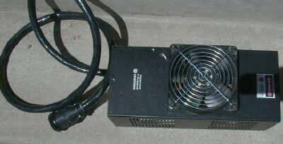
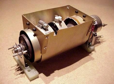
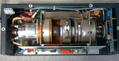
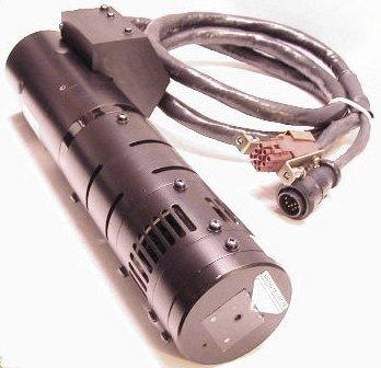
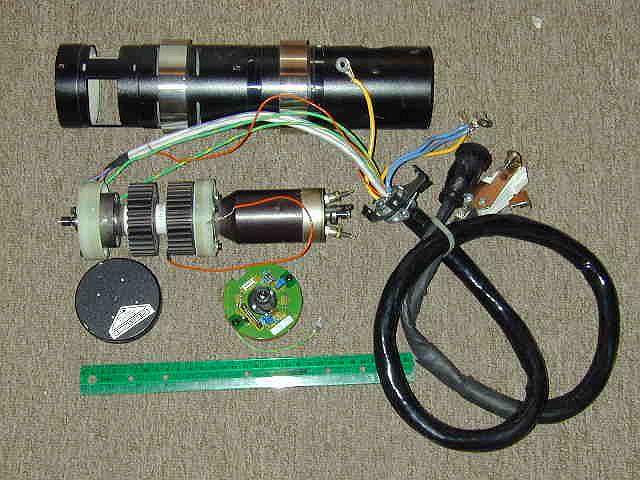
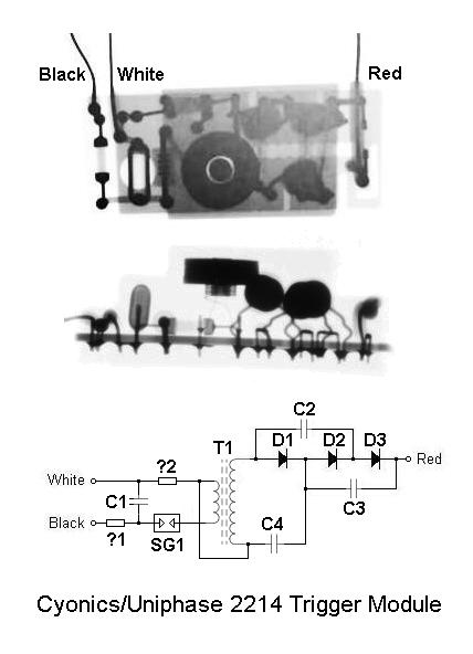
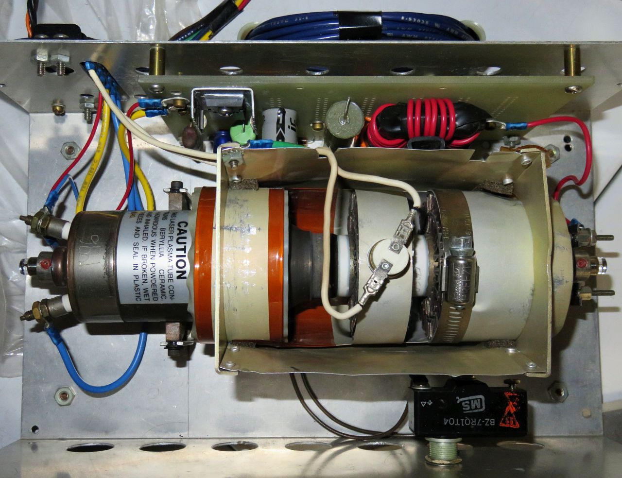
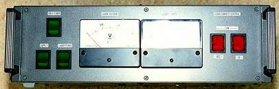
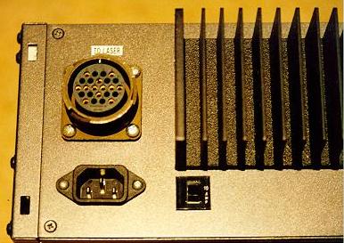
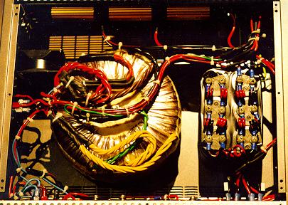
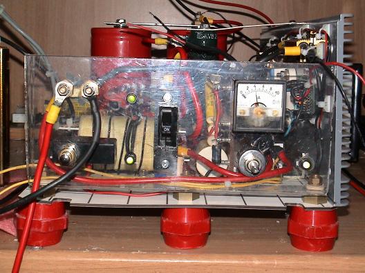
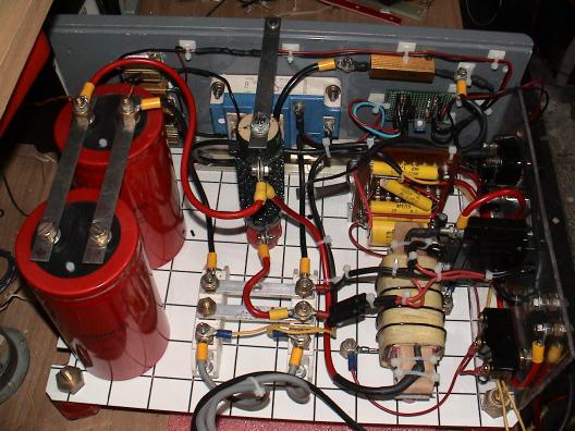
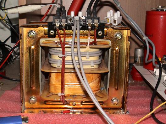
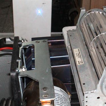