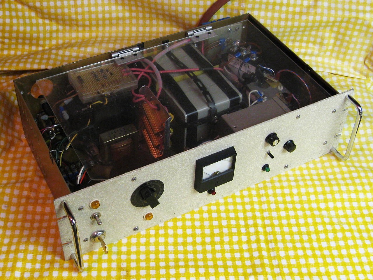
On the top left is the main power switch and indicator and below that the high voltage keylock switch. The timing circuits are enabled with main power so that the repetition rate can be set. Running without high voltage enabled but with charged capacitors is possible.
The Variac controls the high voltage from 0 to approximately 1320 V on the capacitors. The meter and red LED below it show the charge on the capacitors.
The knob to the right of the meter sets the pulse rate from approximately 1 pulse every 2 second to 10 pulses per second. The switch below it selects free run (up), off (middle), single shot fire (down, momentary). When used in this mode, the pulse repeat rate is still limited by the setting of the pulse rate control. The green LED flashes with each pulse.
The knob on the far right selects the pulse type: biphasic (CCW), polyphasic (middle), monophasic (CW).
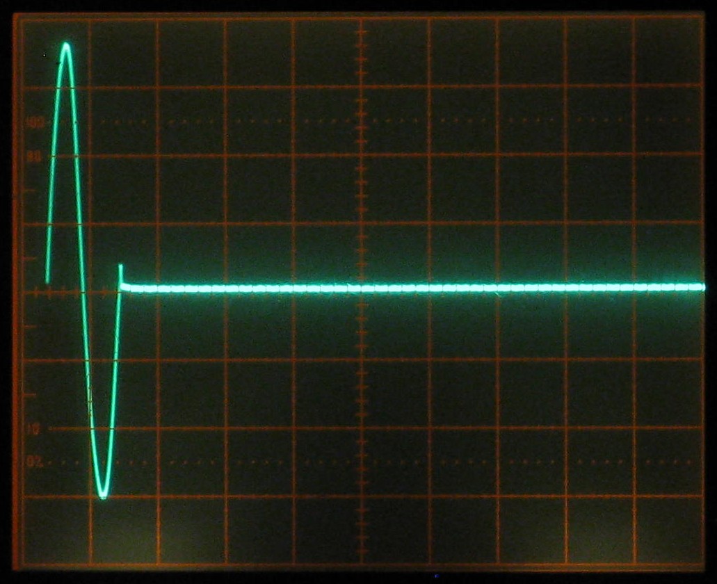
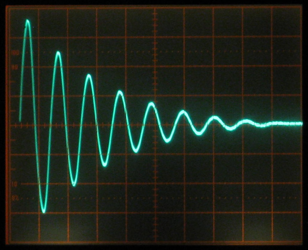
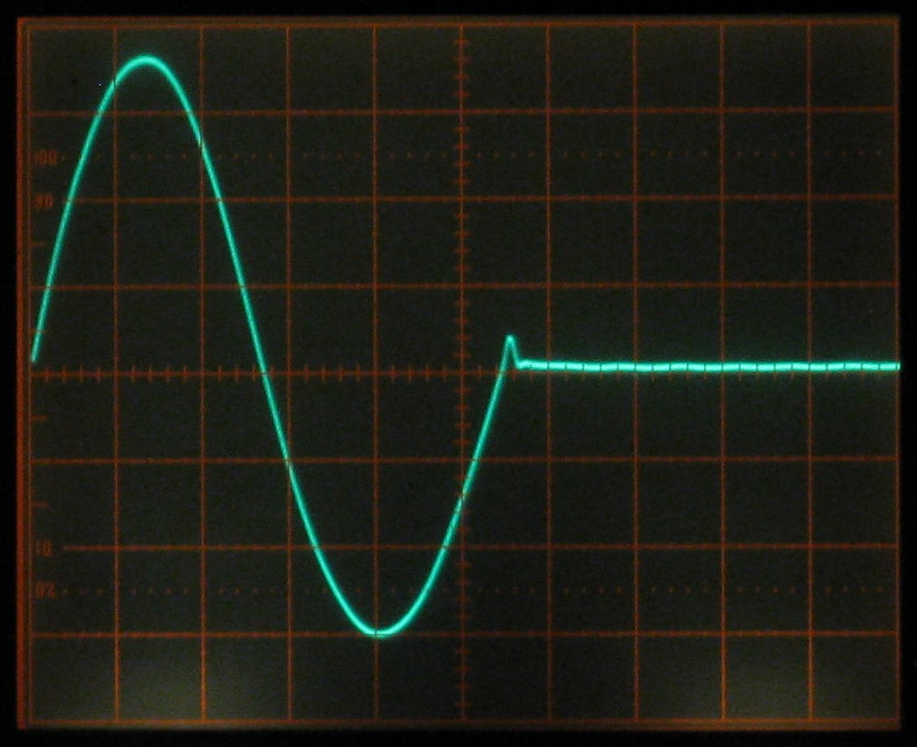
These used a coil with an inductance of approximately 34 µH resulting in a frequency of ~6.1 kHz or period of ~164 µs. The positive half-cycle is through the primary SCR. The negative half-cycle is through its associated parallel diode. The little blip at the end is believed to be due to the reverse recovery time of the primary SCR. (More below.) With another coil of only 10 µH, the damping factor ended up being slightly lower resulting in a more extended decay of its ~10 kHz oscillation.
A spreadsheet for estimating the behavior of the RLC discharge circuit using coil parameters and calculating peak current, peak B-field, B-field a fixed distance from the coil, dB/dt, and more can be found at: Magnetic Pulser Modeler.
A javascript program for estimating the magnetic field produced by 1 or 2 coils can be found at Calculator for Off-Axis Fields due to One or Two Coils
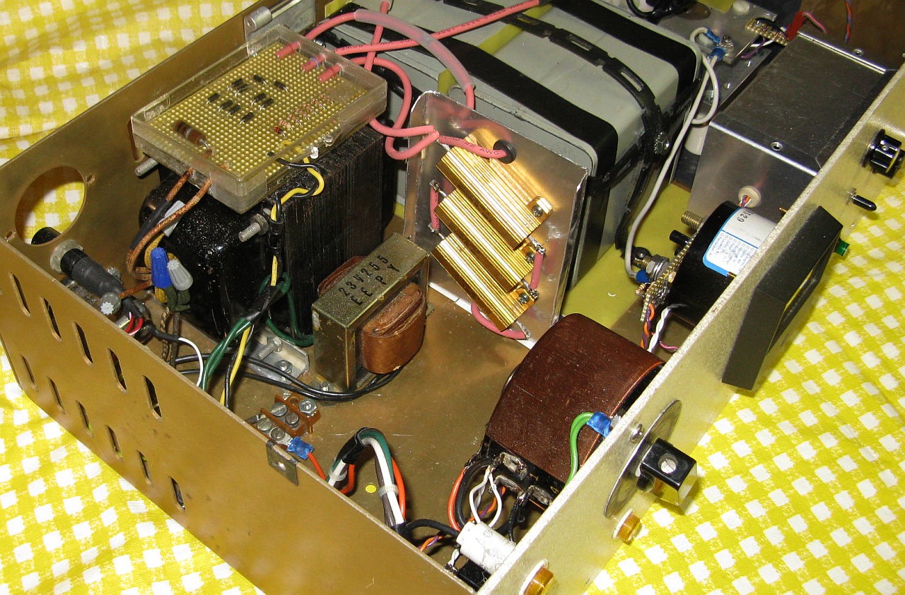
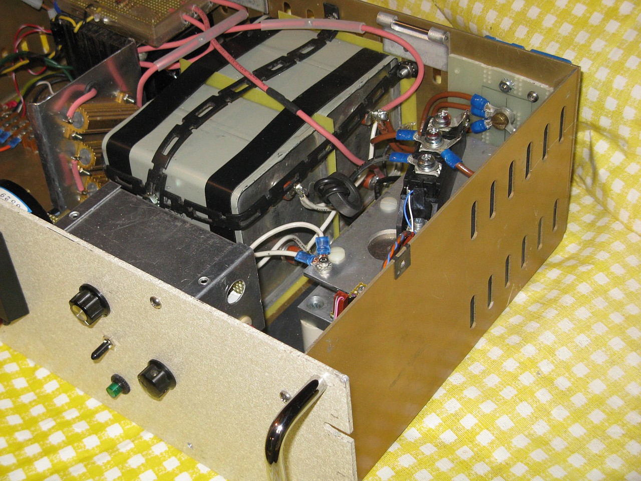
The high voltage power supply uses the power transformer from a large 1950s black and white tube-type TV controlled by a Variac. :) The transformer has multiple line voltage taps and is set to produce the highest voltage. I also wired the otherwise not very useful 5 V and 6.3 V filament windings to the primary to further boost the output. The transformer hums a bit but doesn't get even detectably warm after a few minutes so it can't be too unhappy. With the Variac wired to go up to 110 percent of line voltage, its main output goes up to approximately 950 VRMS. A bridge rectifier consisting of 4 series pairs of 1N4007 diodes feeds the main energy storage capacitor via a 1.05K ohm 150 W series resistor bank resulting the voltage on the capacitors of around 1,450 VDC. The resistor bank both limits the current from the transformer as well as providing isolation during the discharge to maintain a low damping factor.
A voltage divider feeds the meter with a peaking circuit to improve response time. The red HV LED is driven from a split emitter follower. The voltage divider is mounted along with the bridge inside a plastic box for insulation. The monitor circuits are attached to the back of the meter.
A separate 12 V transformer powers the logic and SCR drivers.
The main energy storage capacitors consists of a pair of 10 µF (labeled), 1,500 V pulse discharge capacitors in parallel. Their actual capacitance was measured to be 25.4 µF
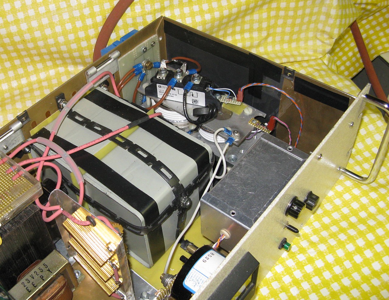
Two high current SCRs and two high current diodes are used to create the three pulse types. The "hockey puck" style 800 A, 1,800 V SCR and 1,500 A, 1,800 V visible in the second photo from the left are a bit over the top in terms of what's required :) These are for the main pulse discharge. The smaller IXYS unit on top implements the free-wheeling discharge path for the monophasic pulse. These are only rated at 95 A and 1,600 V but for low repetition rate high current pulses, should be able to handle 30 times this or more. The same IXYS unit would work for the main discharge except that its turnoff time was found to be too long to be able to select out only the single cycle for the Bipulse, thus the pucks were retained out of convenience.
All three pulse types start with the same 1/4 sinewave as shown in the expanded biphasic pulse below. The peak current is thus similar for all. What happens after that changes for the other two other pulse types.
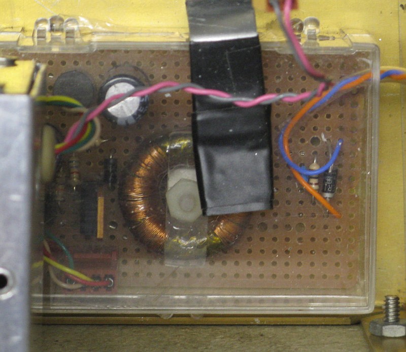
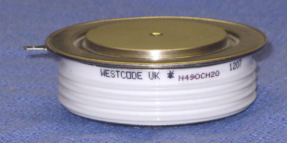
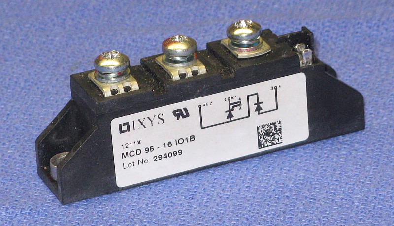
That free-wheeling SCR switch for the monophasic pulse turned out to be the most difficult to implement due to the requirement that its gate and cathode swing up to almost +/-1500 V with respect to the circuit common during the discharge. My first attempt using a home-built ferrite pulse transformer lasted about 3 shots due to insulation breakdown. Ferrite is supposed to be an insulator, correct? Nope, at least not this batch of cores at high voltage. A Westcode N490CH20 Hockey Puck SCR rated 2,000 V, 1,200 A average and over 2,400 A pulsed, that is almost 3 inches in diameter weighing in at around 1 pound was originally installed for the free wheeling circuit. It failed shorted when its gate circuit arced through the trigger transformer core. Remarkably, nothing on the low voltage side was damaged. And the primary hockey puck SCR and diode, which were then discharging into a dead short. also didn't seem to care. The first replacement switch was a combined SCR/diode block (IXYS MCD95-16IO1B). While its current rating is about 1/10th that of the unlucky hockey puck, the low repetition pulse rating should easily be enough, hopefully. The companion high current diode was in series with the SCR (mainly because it was available), with a low current diode (a pair of 1N4948s in series) across the SCR so that the full reverse voltage would be taken by the large diode, hopefully reducing the turn-on time of the SCR. The core of the replacement trigger transformer has 2-3 layers of Kapton tape covered with Epoxy for insulation. :)
Various Coils have been used with this machine.
Air-core coils having an inductance from below 8 µH to over 33 µH were found to work with all 3 pulse types. This is rather surprising at the low end given that the primary SCR needs to recover within 1/2 cycle, which at 8 µH is under 50 µs. Most thyristor specifications don't include a maximum recovery time, and the typical values given are usually 2 or 3 times longer than this. In fact, the IXYS-MCD95-16IO1B was too slow to replace the primary hockey puck SCR and diode, resulting in the biphasic and polyphasic waveforms both being polyphasic. (The mounting and reduced space would have been much more convenient!)
(Coils with an iron core have so far proven to be a disaster either due to core saturation or eddy-current losses resulting in poor damping and/or excessive current. The best case is that the waveforms are terrible or don't change depending on type; worst is that parts blow up. :( :) More below.)
But at a coil inductance of 3 µH (4 or 5 µH total), the free-wheeling SCR self-triggered with a capacitor voltage above about 700 V. So, all three waveforms then looked like the monophasic pulse. :( :) (The same thing happened above around 1,400 V with the 10 µH coil.) The cause is an EM transient picked up either in the wiring to the gate of SCR or the driver. Disconnecting the gate drive cable eliminated this spurious triggering, so it wasn't a problem with the SCR itself. Remarkably, the other two waveforms then worked correctly, even with a full cycle (biphasic pulse) of under 65 µs. Detailed specifications of the primary SCR (a GE 387NX198 found on eBay) have not been located, but it must be unusually fast. :) Adding a 1 µF capacitor across the SCR gate delayed the onset of the self triggering to a somewhat higher capacitor voltage. Adding a 5 µF capacitor caused the free-wheeling SCR in the IXYS block to make a plit'ting sound and fail shorted, which I assumed at the time to be due to too slow a rise in gate drive current. :( However, one of the screws on the IXYS block was found to be loose when I removed it, so that could have been the cause as well. Lucky these are inexpensive on eBay. ;-) I bought a couple spare dual SCR units (IXYS MCC95-16) as spares. Since the diodes in the MCD95-16s were still good, there will be 4 spare SCRs and 3 spare diodes just in case. :) (One of the 3 MCDs I bought already had a blown SCR.) In the end, adding a 10 ohm resistor in series with the gate drive seems to have eliminated the false triggering for bare coils. However, it reappeared when driving a coil in a steel yoke, which resulted in a damping factor of almost unity due to induced current in the center piece. That configuration performed poorly in just about every way, as should have been expected, and it has been retired. The bare coil had an inductance of 8 µH and works fine. Perhaps, the peak current was much higher due to the losses, and pickup from that is what was triggering the free-wheeling SCR. When the SCR in a second IXYS MCD95-16 blew while attempting to drive an iron-core coil (either due to core saturation or excessive eddy current losses), I installed a IXYS MCC95-16 using only one of its SCRs without the extra diodes (leaving the other SCR as a spare!), and that works fine. The problem would arise if the SCR shorted resulting in a dead short across the the coil. But since this thing survived that in the past, so it shouldn't really matter.
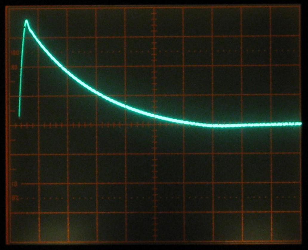
One mystery remains though: The measured time constant of the biphasic pulse and decaying sinusoid is consistent with a damping factor about double what the calculations predict based on the capacitance, coil/cable/wiring resistance, and coil inductance. While there are some losses in the primary SCR and its high current diode, as well as the ballast resistor bank, these shouldn't result in even 10 percent of the observed effect. And yet the decay time for the monophasic pulse is close to the theoretical value. The most likely candidate is the real part of the capacitor ESR. The required resistance of about 0.03 ohms seems high for capacitors of this type but isn't totally out of the question. This would make sense though since the characteristics of the capacitors do not impact the time constant of the monophasic pulse. The specs other than uF and working voltage for the capacitors are unknown. The skin effect of the coil and cable conductors might also contribute a tiny amount. At a frequency of 10 kHz, the skin depth is around 0.66 mm, which is less than one half the diameter of the #14 conductors typically used for the coil (1.63 mm). But this will only increase the effective resistance by a few percent at most.
The controller and its power supply are housed in the shielded Minibox. Whether the shielding is really needed is not known, but there was no point in taking chances with ~1000 A pulses floating around. :) (Even so, there is often a spurious pulse generated when switching the HV off.) The power supply provides regulated 12 VDC using AC from the small transformer mounted on the chassis. The "logic" consists of a pair of 555 timers. :) The first generates the clock for continuous (approximately 0.5 to 10 Hz), or single shot. It's output drives the Pulse LED and the 555 for the SCR trigger with a pulse width determined by Pulse Type: around 50 µs for Bipulse; 2 ms for decaying sinusoid and monophasic pulse. These values should work over a wide range of coil inductances.