For more information, see:
This document contains notes on the construction of a two-frequency Zeeman HeNe laser using an HP/Agilent 5517 laser tube and an Arduino based digital controller.
(The style of some parts may vary slightly from what's shown in the photo.)
The following components are included:
What you will need to provide:
Plenty of possibilities can be found in Sam's Laser FAQ, chapter: Home-Built HeNe Laser, and the schematics in the chapter: Commercial Stabilized HeNe Lasers. Since the output of the Zeeman laser with the waveplates are two orthogonally polarized modes, the same feedback schemes can be used as in a normal two-mode stabilized HeNe laser.
If using the µSLC1 Arduino controller with the Windows GUI, it can serve this purpose.
Organization of two-frequency Zeeman-split HeNe Laser:
The diagram below shows a system similar to what may be constructed using parts in this kit and readily available materials and electronics.

Many variations are possible. The feedback electronics inside the box are not included in the kit (more below). The REF Signal monitor is shown using the waste beam but could also be in the main beam (the polarizer would then need to be at 45 degrees). However, that would require an additional beam sampler plate (not included) which would decrease the output power slightly.
The HP laser tube assembly includes both 1/4 and 1/2 waveplates. Ideally, only the 1/4 waveplate is required. However, having both allows the orthogonality of the F1 and F2 polarizations to be optimized. Keeping the waveplate assembly at the exact same orientation is was originally with respect to the base AND front-to-rear should result in a satisfactory (if not optimal) conversion of qarter wave to linear polarization.
Power and wiring:
The HeNe laser power supply requires a regulated 5-6 VDC power supply at 1.5 A max. A switchmode wall adapter is included in this kit. However, if you'd rather use one of your own, adapters like those for some digital cameras or cell phones should be acceptable, but check to make sure its current rating is adequate and measure its voltage unloaded to confirm it is between 5 and 6 VDC. Jameco, Marlin P. Jones, DigiKey, Mouser, and other electronics distributors will have a suitable unit. Confirm the correct polarity if in doubt. The short red and yellow wires on the HeNe laser power supply brick should be tied together securely (soldered is desireable) and are positive; the short black wire is negative. (The yellow enables the laser when tied to red. For this application, red and yellow should be tied together permanently.) IMPORTANT: If you ordered the kit with a 24 VDC HeNe laser power supply and adapter, the wiring is slightly different! Using the incorrect wiring may destroy the power supply. The following is for the 5 V version:
(All black wires are the same - return/Ground. The other unused wires provide approximately +/-9 V at low current intended to power an RS232 transceiver in the original barcode scanner application.)
It is even more essential that the wiring to the HeNe laser tube have the correct polarity and insulated so there can't be shorts or arcs. Reverse polarity may ruin the tube in a few minutes even though it may appear to light up and lase normally. The end of the tube that has the thick glass capillary is the anode, positive, red, and 91K ohm ballast resistor. It has the HIGH VOLTAGE and must be separated from the magnet frame by air or adequate HV insulation. The voltage can be up to 5,000 V when starting. The end of the tube with the aluminum can is the cathode, negative, black (either black wire of the power supply brick. A short or arc can destroy the HeNe laser power supply and perhaps even the wall adapter.
WARNING: There is over 1,000 V present while running and over 5,000 V at startup on the anode mirror mount of the tube! Stay clear! It probably won't kill you but throwing the tube across the room as a result of a reflex reaction is bad form and failure of the tube due to being smashed is not included in any warranty.
Make sure all connections are secure before applying power. The tube should light almost instantly. The output power may start relatively low (llke 0.7 mW) and climb to between 0.8 mW and 1.2 mW or more. (This modest increase probably won't even be obvious using only Mark I eyeballs.) It should be on continuous with no pulsing, flickering, or sputtering. Once the operation of the tube has been confirmed, power down and discharge the power supply and tube capacitance by shorting between the two ends of a tube with a pair of clip leads, attaching one end to the cathode/black wire FIRST!
Note that there are two beams from the tube. The main beam emerges from the anode-end and will be used as both the main output and for feedback. The waste beam is around 100 times weaker and emerges from the cathode-end. Since the waveplates are required to convert circular to linear polarization, the waste beam CANNOT be used for the feedback unless a second set of waveplates are added. However, it can be used for the internal REF detector if desired, eliminating one beam sampler.
Installing the heater:
For the ~1 inch diameter tube, the 2x3" heater should be wrapped around so it covers nearly the entire circumfrance. (3 inch dimension goes around it.) The Kapton heater has an adhesive backing. Peel off the backing paper and stick it on centered between the two end-caps. For convenience (this is sort of arbitrary) orient it with the wire connection point lined up with the tip-off (the small metal tube where the air was removed and the gas was inserted). Press it firmly in place over its entire surface. Route the red wires toward the cathode-end of the tube. Where the wires attach is lumpy. Allow this to poke out a bit rather than squashing it against the tube which may damage the connections. Wrap some high temperature tape around the heater to keep it secure, but only one layer so as to allow heat to pass to the environment.
Determining the polarization axes of the tube (optional):
This step is only really required if it is intended to use the tube in a (non-Zeeman) stabilized laser. When installed in the magnet, the tube orientation is not critical. However, this is a good exercise in becoming aquainted with mode sweep and how the longitudinal modes behave.
NOT ALL TUBES will work for a non-Zeeman one or two mode stabilized laser, at least not trivially. The tube must have well behaved longitudinal modes. Specifically, it must NOt be a "flipper". It's usually possible to use flippers for this but adds complication.
As noted, the laser tube actually produces 2 beams: A strong one out the anode-end (front) and a much weaker one out the cathode-end (rear). For use in a conventional stabilized laser, the beam sampler can be constructed behind the rear of the tube and use the weak beam. As a side benefit, this is the low voltage end of the tube so shocking experiences will be minimized. However, for the Zeeman laser, this would require another set of waveplates. Thus, a portion of the main beam is split off using a glass plate like like the variable attenuator, and that is used instead. In principle, using the main beam will have slightly better stability, especially for some tubes.
With the tube is powered, place a continuous reading laser power meter in the output beam. (One of the photodiodes connected to a VOM or DMM set to its µA range will suffice.) Use a polarizer to identify the orientations of the polarized modes of the tube. These will be the angles of the polarizer where the variation in power due to mode sweep is maximized. There will be two such angles orthogonal to each-other. For reasons not fully understood, one of these often more or less lines up with the exhaust tip-off (metal tube with red cover at cathode end of tube). Label the axes and adjust the orientation of the tube so one is either vertical or horizontal, whichever causes the tip-off to be closest to the bottom (for convenience, the photons really don't care).
The power varies because the longitudinal modes of the laser cavity are moving through the neon gain curve as the tube expands due to heating. The roughly bell-shaped gain curve results in gain variation depending on its height. If 5-10 VDC is applied to the heater (between the two red wires), the rate of the mode sweep will greatly increase since the tube is expanding faster.
As the tube/heater combination approaches thermal equilibrium where the power input from the electrical discharge in the bore of the laser tube and heater power are balanced by heat loss to the environment, the mode sweep will slow down and eventually stop. If power is removed from the heater at that time, the discharge heat alone will no longer be able to sustain the same temperature, the tube will start to cool, and the mode sweep will reverse.
This shows the mode sweep from a cold start of a tube similar to the type included in the kit.
For thermal stabilization to be effective, what is desired is where a modest amount of heater power is needed to be at thermal equilibrium. Perhaps 20-30 percent of the power in the bore discharge. For the 6 inch tube running at at 3 mA, 900 V, the bore discharge power is just under 3 W. So, 1 W of heater power should be sufficient to allow the laser to stabilize with reasonable immunity to ambient temperature changes. Using a 3 or 4 VDC power supply, it should be possible to simulate the action of an electronic feedback circuit to confirm that stabilization is possible.
A purist might object (due to noise considerations), but this means that a single 5 or 6 VDC power supply could be used for both the HeNe laser power and the stabilizer.
Checking the beam sampler:
Place the PBS on a support so the main beam passes through its center and a deflected beam shoots off to one side. Eventually it will need to be mounted securely, but for now, a block of wood or stack of CDs and CD boxes will suffice. :)
Now use a white card as a screen to observe the beam coming straight through the PBS and the beam being reflected to the side. They will vary in intensity along with the polarized modes coming out the front. One of the photodiodes will be placed behind the PBS cube and the other on the side. If necessary, fine tune the tube orientation so each of the beams goes completely dark periodically during mode sweep. Devise mounts for the PDs so each of the beams strikes its respective PD and any reflections do not go back into the tube.
Removing the HP-5501A glass Tube from the magnet
CAUTION: Although the HP-5501A tube may actually work at least slightly, I do NOT recommend attempting to power it using the included HeNe laser power supply brick. The tube may be hard start or may not stay lit at the 3 mA of the brick, which may kill the power supply, not covered under warranty.
The following assumes that it is desirable to remove the glass tube intact. Else, it becomes a lot simpler. :( :)
Constructing the beat detector:
                                  PD
          +5 to 9 VDC o-----------|<|---------+--------o Output
                                 C   A        |
                                              /
                                           R1 \         Scope or
                                              /         Counter
                                              \
                                              |
               Return o-----------------------+--------o Ground
(The suggested value for R1 is 2.7K which is a compromise between largest amplitude and frequency response. Feel free to experiment with higher or lower values.)
Use this detector to view the Zeeman beat or measure its frequency from the tube in magnet. A polarizer must be placed in front of the PD but without the waveplates, its orientation doesn't matter.
Test the tube for Zeeman behavior:
Temporarily install the tube inside the magnet with adequate insulation to prevent shorts or arcing at the anode end. It should light up nearly instantly, and to the unaided eye, will appear to lase normally. Power it as described above and aim it on the PD (through the polarizer).
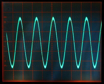
This shows the bare tube snug in the magnet inside some foam padding along with a polarizer and a built up version of the beat detector with a swing arm and 9 V battery inside. The polarizer is also a fancy one but the one in the kit will work just as well. As the tube warms up and the cavity length increases, there will periods during mode sweep where there is a beat at a frequency between 0.8 and 1.5 MHz for the 6 inch tube. The beat will probably be present between 25 to 50 percent of the cycle, and will change frequency somewhat during this time. If 5-10 VDC is applied to the heater (between the two red wires), the rate of the mode sweep will greatly increase since the tube is expanding faster.
Installing the tube in the Zeeman magnet:
Using your preferred mounting technique, slip the tube into the magnet with the anode wire and clip passed through the output optics shroud (with waveplates) so it can be permanently installed. (The Kapton spacer probably isn't needed but installing it will assure that it doesn't get lost!). Double check that nothing can arc or short and then screw the shroud on securely.
The waveplates should be properly adjusted (assuming you didn't mess with them!) as long as the optics shroud is installed in its original orientation (waveplate access plate at the top). DO NOT remove the waveplates from the optics shroud - if they become seriously misadjusted, getting them back may be a pain. :(
Note that with the beam expander, the beam diameter will be somewhat larger (though not the full 6 mm of the HP lasers since the beam diameter from the non-HP tube is smaller) and it can be fairly well collimated. But precise centering is required to align the tube to the beam expander. There is some adjustment range in the oversize holes securing the shroud to the magnet but not that much so special care would be needed in mounting the tube. Unless this rig will be used in an interferometer, the beam expander is not essential.
Unless the waveplates have been tampered with :), their settings should be close to optimal to convert the left and right circularly polarized output of the tube to linearly polarized X and Y components. This can be confirmed using the beat detector and polarizer: Power up the tube and watch for the Zeeman beat. With the waveplates in the beam, there will be an orientation of the polarizer where the signal is a maximum. This should be at 45 degrees. At 0 or 90 degrees there should be no signal at all. If this is not the case, try rotating ONLY the 1/2 waveplate to correct it by removing the cover over the waveplates (1 screw) and then using a pointy tool in one of the holes on the output side closest to the center of the waveplate assembly to rotate the barrel in the appropriate direction. DO NOT touch either the outer set of holes on either side, or the 1/4 waveplate on the tube-side.
Closing the loop:
To stabilize the laser so that the position of the modes is under automatic control with a Zeeman beat requires some electronics to first run the tube in "Preheat Mode" so that the temperature of the tube/heater combination levels off somewhat above ambient, and then to "Lock Mode" to allow the output of one or both photodiodes to take control.
If you're willing to switch from Preheat to Lock mode manually, the required circuit can be as simple as 2 basic electronic components - a resistor and a power MOSFET. This won't have superior performance but is quick and easy to get working and therefore will provide nearly immediate gratification. :)
Much more sophisticated approaches are possible including a fully digital control system with wireless Internet access and data logging. :) Except the Web access, the Micro-Stabilized Laser Controller 1 provides a very flexible digital control system for 1 and 2 mode lasers. See:
µSLC1 is an Arduino-based system that interfaces via USB to a Windows PC for monitoring and adjustment of stabilization parameters. It can run stand-alone as well. I can provide all the electronic parts and the Windows GUI and microprocessor firmware at modest cost. (In fact, the software and firmware can be downloaded via links in the manual, above.)
Or if you'd just prefer to use a few basic parts, an intermediate level of complexity similar to that used in many commercial stabilized HeNe lasers is certainly well within the reach of someone with a moderate knowledge of electronics. This would use a couple op-amps to to act as a transimpedance amplifier for the photodiodes and implement Proportional Integral (PI) control loop.
Assuming a basic but not totally minimal approach, one of the following should be suitable as a introductory exercise in laser stabilization. These were intended fro non-Zeeman dual-mode stabilization but one the beam passes through the waveplates, the result is similar.
Note that both these circuits have the photodiodes paralleled with opposing polarity with a single op-amp rather than separate preamps and a difference amp. To do it this way will require rewiring the beam sampler.
However, unlike the non-Zeeman case where one can lock on either side of the gain curve depending on the polarity of the error signal, with the Zeeman laser, there is only one place to obtain a beat. In other words, it's possible to lock so that the two components - F1 and F2 - are equal in two locations. One is where the Zeeman-split longitudinal mode is between the split gain curves and there will be a beat. The other is where there are actually two separate (non-Zeeman) longitudinal modes with equal amplitude but far far away at the longitudinal mode spacing of the laser tube. In that case, there will be no beat without a fancy high speed detector since the frequency would be over 1 GHz.
To make everything fully automatic, either a simple timer as a delay from power-on, or a monostable circuit that detects when the mode sweep cycle exceeds a preset time can be used to do the switchoever at the once the tube has reached operating temperature.
For more detailed descriptions and other options, see the sections of the Laser FAQ starting with: Inexpensive Home-Built Frequency or Intensity Stabilized HeNe Laser.
Or, use parts of the circuitry of a commercial stabilized HeNe laser like the Spectra-Physics 117 or Coherent 200. There are complete schematics of these in the chapter: Commercial HeNe Lasers.
Enhancements/experiments: