
For more information, see:
This document contains notes on the construction of a two-frequency Zeeman HeNe laser using the tube assembly from a Hewlett Packard (HP), Agilent, or Keysight 5517 B/C/D laser or similar Z4303/N1211A tube. These are fully functional but do not meet specifications for any standard model and/or have an output power lower than minimumm spec. But they are still useful for education/research/experiments. The photos below show a set of typical parts:
(The style of some parts may vary slightly from what's shown in the photo. There is no non-Arduino version of this kit but the needed tube assembly and power supply can be purchases separately.)
The following laser components are included (top pane of photo):
They may include a beam collimator providing a 1-2 mm beam, suitable for use up to 2 feet or so, or beam expander providing a beam up to 9 mm. A separate beam expander can always be used to, well, expand the narrow beam. ;-) BUt 3 or 4 mm beam expanders may be provided upon request.
The following control components are included in the Arduino version ONLY (bottom pane of photo):
See important CAUTION about powering the Atmega board in the µSLC1 manual. Specifically, DO NOT power the board using +12 VDC to VIN at the same time the USB is plugged in. Only use 12 VDC for the heater. While this is supposed to work, doing so killed (probably) the USB chip on one of my Atmega boards when the 12 V supply was switched on. The cause is not known. When the controller is NOT attached to USB, then it's OK to use VIN to power the board.
What you will need to provide:
Note that when using the Attenuator Plate (AP) as a beam sampler, it should oriented at a small angle (much less than 45 degrees) to minimize effects on polarization. 15 to 20 degrees is recommended as shown below:

Once the µSLC1 Arduino controller with the Windows GUI is operational, it can serve this purpose.
Organization of two-frequency Zeeman-split HeNe Laser:
The diagram below shows a system similar to what may be constructed using parts in this kit and readily available materials and electronics.

Many variations are possible. The Arduino implements the electronics inside the box. The REF Signal monitor is shown using the waste beam but could also be in the main beam (the polarizer would then need to be at 45 degrees). However, that would require an additional beam sampler plate (included if needed) which would decrease the output power slightly. The diagram above shows the so-called "Long" tube. The "Short" tube construction is shown below:
The main practical difference is that there is no waste beam from the Short tube so beam samplers must be used for both REF and feedback.
Power and wiring:
The use of the HP 5517 tube assembly simplifies the wiring and makes shocking experiences less likely since the high voltage is safely enclosed with proper connectors.
IMPORTANT: Since the tube current passes through the red/violet wires, it is critical that it has a place to go. Thus the resistor "R LT1" is essential to provide a path bypassing the heater drive transistor (Q1) on the µSLC1 PCB. Without a bypass, the tube current will attempt to go through the transistor when it is off and may blow it and possibly other stuff as well. The value is not critical - anything from 100 to 2K ohms should be acceptable. But is should be soldered directly across the tranistor so it can't come loose.


Test the tube and wiring by powering ONLY the 15 VDC adapter. The tube should light between instantly to after a few seconds. Some tubes may take longer and shining a flashlight on the back of the tube may help some reluctant tubes to start. ;-)
There should be an orange glow inside the tube (most visible at the back) and a red laser beam out the front. It should not flicker, sputter, or go on and off. If it does, which connections and confirm that the correct adapter is being used and the voltage to the brick is between 14 and 16 VDC.
The Quarter WavePlates (QWPs):
The raw output of the HeNe laser tube in the Zeeman magnet consists of lasing modes that are left and right circularly polarized. For these to be useful for stabilization feedback and in an interferometer, it is necessary to convert them to orthogonal linearly polarized modes. This is normally done with a Quarter WavePlate (QWP) oriented with its optical axis at 45 degrees to the base (X and Y axes). These tube assemblies actually have both a QWP and Hall WavePlate (HWP) so the conversion can be optimized without having to rotate the tube. DO NOT ATTEMPT TO ADJUST THE BLACK RINGS OF THE WAVEPLATE ASSEMBLY!!!! They are set optimally and without detailed instructions, restoring operation is hopeless. ;( ;-) ALSO, DO NOT REMOVE IT WITHOUT LABELLING ITS ORIENTATION. Flipping it or rotating it 60 degrees will result in unexpected behavior. It has been set to provide optimal separation of the two polarized outputs aligned with the X and Y axes of the laser.
If using the waste beam for feedback (which is unlikely as noted above), an external QWP will need to be installed at the back of the tube.
Constructing the beat detector: This one is just for testing or if µSLC1 is not being uused:
                                  PD
          +5 to 9 VDC o-----------|<|---------+--------o Output
                                 C   A        |
                                              /
                                           R1 \         Scope or
                                              /         Counter
                                              \
                                              |
               Return o-----------------------+--------o Ground
The suggested value for R1 is 2.7K which is a compromise between largest amplitude and frequency response. Feel free to experiment with higher or lower values.
Use this detector to view the Zeeman beat or measure its frequency from the tube in magnet. A polarizer must be placed in front of the PD at 45 degrees for the main beam, but its orientation doesn't matter if using the waste beam.
Since the tube isn't locked and stabilized, the beat will come and go so you will have to catch it each time. ;-) Depending on the specific tube and split frequency, it may only be present for a small part of the mode sweep cycle.
Note that while µSLC1 has a split (or "REF") frequency input which will display in the Main Window of the GUI, it requires a TTL-compatible signal. This can be generated by an HP/Agilent optical receiver, SG-OR3 ONLY if one of its output capacitors is removed and bypassed, or an equivalent home-built circuit. Either REF or REF- can be sent to the µSLC1 REF input. Do NOT use an AC-coupled output (capacitor or transformer) as bad things may happen.
Test the tube for Zeeman behavior:
Power the tube. To the unaided eye, it will appear to lase normally just like a tube without a magnet. Aim the main beam through the polarizer to the PD.
As the tube warms up and the cavity length increases, a beat will appear periodically during mode sweep varying in frequency. Depending on the tube, the beat will only be present for a portion of the cycle, and will change frequency somewhat during this time. With a greater magnetic field, the percentage of the cycle over which there is a beat decreases. For example, it may be 50 percent for a tube with a low magnetic field and peak frequency of 1 MHz but less than 10 percent for an HP-5517D laser which locks with a ~3.75 MHz split frequency.
If 5-10 VDC is applied to the heater, the rate of the mode sweep will greatly increase since the tube is expanding faster, which is how the video was made.
Confirm that the QWPs are Correctly Adjusted:
For HP tubes, there should be no need to adjust anything but it won't hurt to confirm. The shipping company may have decided to have fun and twiddle it. ;-)
Since the tube isn't locked and stabilized, the beat will come and go so you will have to catch it each time. ;-)
Note that while µSLC1 has a split (or "REF") frequency input which will display in the Main Window of the GUI, it requires a TTL-compatible signal. This kit currently doesn't include parts for that, sorry. A simple circuit that should be suitable can be found at Teletrac 150 Reference Receiver Schematic. Either REF or REF- can be sent to the µSLC1 REF input. DO NOT connect an optical receiver like an HP-10780 or SG-OR3 with an AC-coupled signal directly as bad things may happen.
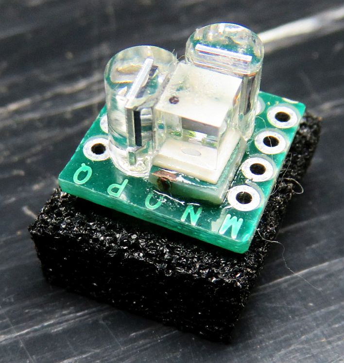
Testing the photodiodes response to laser light:
This is used to set up the feedback optics and electronics.
The following assumes that the QWP has been installed to conver the circular polarization to linear polarization and the resultin polarization axes are known.
To test the response of the silicon PhotoDiodes (PDs) included in these kits, a simple test circuit using a few resistors, a 5 VDC power supply (or USB charger cube), and DMM can be constructed before connecting the stabilization controller. To determine the polarity of the PDs, use the DMM on the "Diode Test" range across the pins: The voltage drop will be between 0.5 and 0.6 V if the red probe is connected to the anode. The polarity is usually opposite for a VOM but they are only found in museums these days. ;-)
Wire up a test circuit as follows:
                                  V1
                                   o
             R Protect       PD1   |  R Load 1
   +5 VDC o----/\/\----+-----|<|---+---/\/\-----+
                       |                        |
                       |          V2            |
                       |           o            |
                       |     PD2   |  R Load 2  |
                       +-----|<|---o---/\/\-----+
                                                |
                                                |
  GND/RET o-------------------------------------+
Note that with the magnet installed, the appearance of the mode sweep is distinctively different than it is without them.
Closing the loop:
To stabilize the laser so that the position of the modes is under automatic control with a Zeeman beat requires some electronics to first run the tube in "Preheat Mode" so that the temperature of the tube/heater combination levels off somewhat above ambient, and then to "Lock Mode" to allow the output of one or both photodiodes to take control.
If you're willing to switch from Preheat to Lock mode manually, the required circuit can be as simple as 2 basic electronic components - a resistor and a power MOSFET. This won't have superior performance but is quick and easy to get working and therefore will provide nearly immediate gratification. :)
However, the Arduino kit includes components to construct a fully automatic controller using an Atmega Nano 3.0 Arduino-compatible microprocessor platform.
Assembly of the electronics and operation of the µSLC1 Windows GUI may be found in the Micro Stablized Laser Controller 1 (µSLC1) Installation and Operation Manual.
However, unlike the non-Zeeman case where one can lock on either side of the gain curve depending on the polarity of the error signal, with the Zeeman laser, there is only one place to obtain a beat. In other words, it's possible to lock so that the two components - F1 and F2 - are equal in two locations. One is where the Zeeman-split longitudinal mode is between the split gain curves and there will be a beat. The other is where there are actually two separate (non-Zeeman) longitudinal modes with equal amplitude but far far away at the longitudinal mode spacing of the laser tube. In that case, there will be no beat without a fancy high speed detector since the frequency would be over 1 GHz.
The horizontal and vertical mode signals from the PBS should have a decent amplitude p-p and will be roughly 180 degrees out of phase, something like the screen shot below from the µSLC1 GUI:
The ragged green and orange plots of of the modes is characteristic of Axial Zeeman behavior. The QWP orientation should be set to maximize their amplitude.
If using the waste beam for feedback, test and adjust both QWPs and label their orientation. Then transfer one to the main beam using the same orientation. (This is probably not recommended due to the lower output power of the waste beam.)
Enhancements/experiments: