

Note: Most references will be to Hewlett Packard (HP) components as they are most common. But some equivalents from Excel or Zygo may appear from time-to-time so be prepared for confusing labeling. ;( ;-)
This guide deals specifically with setting up the laser, interferometer, optical receiver, and their power supplies. Complete information on wiring the chipKit DP32 or SG-µMD1 board to the REF MEAS signals and running the µMD1 Windows GUI may be found in the µMD1 Installation and Operation Manual or µMD2 Installation and Operation Manual. (Note: These and the links below open in a single new tab or window.)
IMPORTANT: If any of the interferometers are from Excel in a kit sold prior to 2024, it will be necessary to confirm that the Polarizing Beam Splitter (PBS) cube (labeled 1011A or 1012A) functions correctly. I have recently come across a small number of Excel PBSs - even new/NOS ones - where the coating on the diagonal is defective even though it looks pristine by eye. At the normal (perpendicular) angle of incidence they are either marginal or totally ineffective at behaving like a PBS.The simplest way to test the PBS uses the 5517 laser with a linear polarizer (LP, which can be one for a camera but NOT a circular polarizer). Power the laser until READY comes on solid. Remove everything from the interferometer - cube corner(s) and quarter wave plate(s) - and place it in the beam with the label at the top and an edge parallel to the beam. Position the LP in the beam between the laser and PBS with its axis of polarization vertical. If the PBS is good, there will be almost no light coming out the front with most being reflected to one side. (If the axis of polarization for the LP is not labeled, rotate it until almost no light gets through. For a defective PBS, there may be no such orientation even if the incident beam is perfectly perpendicular to the face of the PBS.) Rotate the PBS a few degrees either way around the vertical axis and very little light should still get through. Rotate the PBS 90 degrees around the vertical axis and repeat. The behavior should be similar except that the reflected beam will exit from the opposite face. If either test behaves strangely, contact me for a replacement. I will pay shipping for the replacement and to return the original. Sorry about that. These have been included in the Hobby Special kits for several years but just recently, someone found a defective one. It had never occurred to me to even test these as high quality PBS cubes should not go bad, or be bad from the factory. I'm leaning more toward degradation of the dielectric coating as the cause even though there is no visible evidence of it.
All interferometer PBSs are now routinely tested for this issue, so they should all be acceptable going forward. I have not found any defective genuine HP/Agilent PBSs, but even some of those have a very small acceptance angle. But never fear, the Hobby Special limited unlimited warranty will cover the interferometers for the duration of your research project. Just make sure alignment is PERFECT!
More information than you probably need or want to know on this technology may be found at:
The following is just a summary.
The technique here is based on what's known as "heterodyne interferometry" which utilizes a two-frequency HeNe laser and special optics to precisely measure changes in distance (called "displacement") down to the nanometer scale. Other types of measurements including those for angle and straightness can be performed with appropriate interferometer optics.
In a nutshell, the two-frequency laser sends out a pair of superimposed beams that differ in optical frequency by a relatively constant amount (called REF), one polarized horizontally and the other polarized vertically. REF is typically in the low MHz range which provides a convenient "carrier" for signal processing. Optics separate the two beams, sending one to a (generally) fixed reflector, and the other to some tool or device whose position needs to be measured precisely. Both beams then return to an optical receiver where another difference frequency (called MEAS) is generated. With no movement, REF and MEAS have the same frequency and the phase relationship between the two beams is constant. But if the tool or whatever moves, the frequency and thus phase relationship between REF and MEAS will change due to doppler shift. With the simplest interferometer optics, a phase change of 360 degrees represents a position change of 1/2 wavelength of the light from the laser, approximately 632.8 nm for the HeNe lasers most often used. The precise wavelength for these lasers is specified to 6 decimal places (e.g., 632.991372 nm for the HP/Agilent 5517B) with a wavelength accuracy of 0.1 ppm over the life of the laser.
Using the two-frequency approach rather than a basic Michelson or similar interferometer, among other things makes these systems more immune to misalignment by eliminating issues of fringe counting and direction, and fringe contrast, and they are less susceptible to changes in signal level as the laser ages, dust settles on the optics, or alignment changes.
The diagrams below show the organization of a single axis system using µMD1 or µMD2 for the processing and measurement display. Both provide capabilities similar to those of an HP-5508A Measurement Display - and a lot more. For 2 or 3 axes, the interferometer optics, remote (Test Arm) reflector, and optical receiver would be replicated, along with 1 or 2 non-polarizing beam-splitters to divide the output of the laser.
By default these systems will come with µMD2. However, while the µMD1 kit is no longer available, the SG-µMD1 PCB and Digikey "Cart" with all the requireed electronic components may be substituted at slightly lower cost..
IMPORTANT: The laser provided with this kit is currently a some version of a 5517. Nearly all are in the smalll rectangular case used by the 5517B/C/D etc, but a few may be in the larger trapazoidal case of the 5517A. Functioanlly they are identical.
Since 5501Bs have been used in the past, info on them is also included here. The differences are as follows:
The photo below shows the typical parts included in a single axis system using a 5517 laser:
There is also a lower cost option which substitutes a generic Cube-Corner (CC) for one of the 10703A CCs of the PMI. as well as a more basic option with a 10702A cube, 10703A CC, and generic CC for implemenation of a linear interferometer ONLY.
Except for the unmounted generic CC, these components may be from Hewlett Packard/Agilent/Keysight, Excel, or Zygo. They are all physically and functionally equivalent.
µMD2 can also be used with angle and straightness optics, but those from HP/Agilent are extremely expensive, even surplus. However, in principle, these can be built from less expensive standard parts.
Note: The 10780F/U does not have a focusing lens or polarizer since it is normally intended for use with an optical fiber. There is ample power here such that a focusing lens should not be required and a polarizer will be pre-attached, so nothing additional needs to be done if the optical receiver is a 10780F/U.
The optical receivers will come with a pair of red and black wires for power. Red is for +15 VDC but double check! A pair of bare male pins stuffed into the connector are for MEAS.
Nearly all the optical receivers are from Hewlett Packard/Agilent/Keysight (10780) but a few may be from Excel (1031). They are all physically and functionally equivalent.
There is a link below to the µMD2 manual which includes Heathkit™- style instructions for its assembly and testing.
There will be cut wires for connections and/or screw terminal blocks that plug onto the power pack output barrel connectors. (However, if one of the power packs is rated 16 VDC as noted above, 1 or 2 diodes MUST be installed in-line with the output. Observe the polariaty - the bar on the diode(s) should face AWAY from the power pack. These usually run slightly high because the current used by the laser is well below their ratings, so 2 diodes is probably an acceptable default.)
For the 5501B version, the connectors and power packs will be different but all other parts are essentially the same.
Styles of some of these parts may vary.


Photo of Typical Parts for Single Axis System using 5517 Laser (Left) and 5501B Laser (Right) with Original µMD1
The interferometers shown are the 10702/6A PBS with 10703A CC, 10722A QWP, and generic CC
For a 2-axis system, a non-polarizing beam-splitter is necessary to divide the output of the laser into two approximately equal parts, and a second interferometer and optical receiver are required. For a 3-axis system, an additional set of similar parts is required. The beam-splitters may be 1:1 or 2:1. Either is acceptable. The power won't be equal but the laser should have enough power. The µMD1 and µMD2 boards can handle up to 3 axes.
Note that the laser included with the single axis system may be lower power than with the 2 (or 3) axis system, but should still have enough power for those if desired.
Power supplies/wall adapters
CAUTION: ONLY change connections (including plugging or unplugging stuff) with power OFF! Otherwise bad things may happen.
The laser requires +/-15 VDC. Therefore, a pair of power supplies are provided.
The smaller power pack is for the -15 VDC, used only by the laser. The common point between them is to the negative of the +15 VDC supply and the positive of the -15 VDC supply. One or both may have DC power plugs attached as well mating screw terminal connectors or power jacks. These may be used, though soldering the wires is more secure and eliminates the chance of plugging the wrong power pack into the wrong connector.
There may also be an option to substitute a cased +/-15 VDC switchmode power supply for the power packs. Wiring of that should be self explanatory as all the connections are labeled. The only "gotcha" is that the two outputs may be totally isolated so that the common point will need to be tied together. Take care when wiring this supply, especially the line voltage inputs. Add strain reliefs or tape so that wires can't be ripped out.
Unless you opted for the optional HP cable, it will be necessary to wire up the laser head connector to the DC power packs and REF input to REF header on the µMD1 board. With the optional cable, two sets of wires from the cable are built-in and they just need to be attached to the power supplies and REF/MEAS on the µMD1 board.
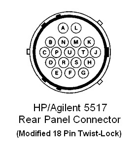
   Pin      Function
 ------------------------------------------------------------------
    A       No Connection on 5517 (MEAS signal level on 5518A)
    B       ~MEAS (Not used on 5517) (2)
    C        MEAS    "          "
    D       Signal Return (MEAS)
    E       ~REF (Zeeman beat signal from internal optical
    F        REF  receiver's differential line driver.)
   G,H      Ground
    J       +15 VDC Sense
    K       +15 VDC
    L       -15 VDC
    M       +15 VDC
   N,P      Cable Shield
    R       Signal Return (REF)
    S       Ground
    T       +15 VDC
    U       Cable Shield
The +15 VDC output of the power pack should be wired to all of the +15 VDC pins on the connector - J,K,M,T. A single fat wire can be run to the supply (e.g., #18 AWG) with short lengths of #22 for each of the connector pins. (If the power supply you are using has a voltage sense input, pin J can be run separately to that.)
Ground should also be wired to all its pins - G,H,S - in a similar manner.
The current for the -15 VDC supply, pin L, is low - less than 100 mA - so a single #22 wire is sufficient.
All other connections should be soldered or secured with wire nuts and/or screw terminals. DO NOT just wrap them together! Loose connections creates reliability issues and kills stuff.
With an HP laser head cable (10791 or 10881), hooking up power is as simple as connecting 3 wires. BUT THE HP CABLES HAVE A FUNNY COLOR CODE for power! The power cable is the one with three wires with the following colors:
They will probably just be stripped wires though stock HP cables may have spade lugs or a DIN connector. It would be worthwhile to confirm continuity through to the laser head connector with a DMM using the pinout for it, above, or even to the fuses inside the laser head.
There will likely also be another connector on a thin part of the cable, probably a funny 4-pin BNC like one that mates with the 10780 optical recevier. That connector is actually for REF when using one of the HP measurement boards. For our purposes, the cable will need to be cut at a location that provides a convenient length and then wired (1) for the REF input to µMD2 (or µMD1 if you found this in a time capsule) and (2) the 4-pin BNC for the output of the 10780. The color coding for those wires is also strange and it is not known whether it is the same for all versions of the cable, so a DMM will be required.
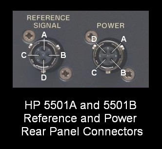
5501B Reference Connector
   Pin      Function                              Socket View
 ---------------------------------------------         A
    A*      Accessory +15 VDC fused                    o
    B*      +15 VDC return                         D o   o B
    C       Reference (difference) frequency           o
    D       Complement of pin C                        C
5501B Power Connector
   Pin      Function                              Socket View
 ---------------------------------------
    A       +15 VDC input                          D o  o A
    B       -15 VDC input
    C*      +5 VDC output (test-point)             C o  o B
    D       Power ground
One of the circular connectors provided with kit will fit the POWER connector. The other will probably need to be modified to fit the REF connector as the standard connector must have its inner shell rotated by 45 degrees to fit. If the two connectors differ, the one for REF will have pins that are not installed, but they may both be like that. The inner rubber shell that holds the pins needs to be pressed out and rotated 45 degrees. I usually do that by trimming around the edges with a thin blade to free it up and then carefully pushing it out using a rod or the butt-end of a large drill bit on a drill press. Then rotate the shell by 45 degrees in the correct direction and push it back in. After confirming it's in the proper orientation so the labeling is correct, some rubber adhesive can be added to secure it. But that's usually not needed as it will be reasonably tight without it. Alternatively, or until you get up the courage to abuse the connector, inserting pins for REF and REF- will work fine. The GND is not even needed as long as there is a GND running to the chipKit or SG-µMD1 board from the PWR connector(junction of the - on the +15 VDC power pack and + on the -15 VDC power pack).
10780A/B/C optical receiver
The mating connector for these is a strange 4 pin BNC, which is unobtanium for less than 3 arms and 2 legs (if one can find it at all). Therefore, where a mating connector has not been provided, two male pins and a 2 pin female connector has been included that will mate with it. The 2 wire power cable will probably already be plugged into the 10780 and the color of the wires is correct - red for +15 VDC and black for GND/common. But never assume I didn't make a mistake, so double check it! The male pins will need to be soldered to wires for MEAS. Put heatshrink over them once attached to wires to prevent shorts and secure with hot-melt glue if desired.
   BNC Pin   Function
 -----------------------------------------------------------------
  1 (LL,F)    ~MEAS (Zeeman beat signal pair from
  2 (UL,F)     MEAS  differential line driver.)
  3 (LR,M)    Return (also BNC shell and receiver case.)
  4 (UR,M)    +15 VDC

        _____
       |     |
       |     |
       | TP  |
       |     |
       |     |
  MEAS | x o | +15 VDC
 ~MEAS | x o | Return
       |_____|
(Sometimes the connector insert gets rotated slightly. But the "x" denotes a socket while the "o" denotes a pin.)
If there are a pair of wires sticking out of the 10780, red is +15 VDC and black is GND/return. The pins are for MEAS/~MEAS.
If you are fortunate enough to have received a mating connector, or better yet, one with a piece of cable attached, use a DMM to confirm the connections since the color coding varies.
To avoid ground loops, the case of the 10780 should NOT be connected to anything - use insulating "hardware" to secure it to the optical table or whatever. The 10780 originally comes with rectangular black plastic insulators, but these often have a habit of disappearing after awhile. Nylon washers with Nylon screws work just as well.
There may be a gain trim-pot accessible on the top of the 10780 (B version and higher). If response is erratic, it can be adjusted. Usually they can be turned all the way up. If that results in instability, just back off until it quiets down. If the optical receiver is a 10780A, the gain adjustment is internal. Normally, these do not need adjustment. Regardless, it will probably be fine without adjustment. However, if the laser locks (READY on solid) but there is no output (or signal LED) on the 10780, the gain may be set too low. (Though more likely, the alignment needs tweeking.) check the REF signal from the laser either with a scope or the REF readout on µMD1 to confirm that it is actually locking correctly. Around 100-120 µW should be sufficient for the laser to lock; the 10780 requires under 10 µW to produce a valid signal. Also, if you have a 10780F or 10780U with a black or silver fiber connector instead of a lens instead of a 10780A/B/C, it has no lens and no polarizer so there may be no signal unless the laser power were higher and a linear polarizer at 45 degrees was added in front of the optical window. See the notes below.
"TP" is the single pin via a feed-through used to monitor signal level during interferometer alignment. Its output is non-linear, being compressed at the upper end with strong inputs. Monitoring it with a DMM or scope is useful during interferometer alignment.
Notes on the types of optical receivers
In nearly every kit going forward, the optical receiver will be ready to go and nothing needs to be done to it, so the following is for information only. And it matters only if using free-space beams; for use with optical fibers, standard remote fiber receivers will be provided.
Initial testing
(The following assumes a 5517 laser. Contact me if you dug out a moldy 5501B version of the kit from your attic. ;-)
Double check your wiring and then apply AC power to both power supplies and measure their output voltages with no load. Their outputs should be close to +/-15 VDC.
Remove AC power, wait for the voltages on the supplies to decay, and then connect the laser. Turn power back on. Immediately, 3 of the 4 LEDs on the back of the laser should come on - all except READY. Anywhere from instantly to awhile after that, a beam should appear. Make sure the turret at the front of the laser has its large hole at the top.
IMPORTANT: Some lasers may require up to a minute or possibly even more for
the beam to appear. While the laser in the kit is probably high mileage,
even youthful $10,000 lasers may take some time to start. But if there isn't a
beam within a couple minutes, power down and double check the power the
power supplies and connections. Others may not restart
immediately if powered off and back on again or may flicker - wait a few
minutes before repowering if this is the case. Failure to do so may result
in damage to both the laser tube and HeNe laser power supply brick inside
the laser. If none of this helps, please contact me.
CAUTION: DO NOT plug or unplug connectors until the voltage has decayed
to close to 0 V (indicated by ALL LEDs on the back of the laser head
going out). If pins make contact in the wrong order, an internal fuse
in the laser may blow at the very least. But it could be worse. It wouldn't
hurt to wire an LED+current limiting resistor across each power supply
output to monitor this (though the LEDs on the laser will serve when
connected).
After a couple minutes, the READY LED should start flashing. With a beam present, after another 2 minutes or so, it should stay on solid. The laser is ready for use. (A minute or more possible for the 5501B.)
Aim the 10780 directly into the laser. (It must be roughly aligned with the X or Y axis to get a signal.) The green LED at the top of the optical receiver should light indicating that it is detecting the f1/f2 difference frequency. An oscilloscope on MEAS or ~MEAS would then show a squarewave at the REF frequency. There is a gain adjustment inside the 10780 which affects the sensitivity, especially for small signals. For the 10780A, it is hidden by the top cover. Usually, there should be no need to touch it, but on the off chance that it had been set too low, loosen the small screws at either end of the 10780A and remove the top cover. It's the trimpot facing up. Turn it fully clockwise. (DO NOT touch any other trim-pot.) At the same time, drill a hole in the cover at the trim-pot location for the future. :) (For the 10780B/C/F/U, there is an access hole in the top cover.) Sometimes, there will be instability if turned too high. If a signal is detected with no beam into the optical receiver, back it off.
Connecting µMD1 or µMD2
µMD1 usually comes with headers and mating connectors while µMD2 usually comes with screw terminal blocks, which are handier if cables don't need to be changed. One type can be substituted for the other - parts are readily available.
Cables will need to be constructed for REF from the laser and MEAS from the optical receiver. For runs of a few feet or less, twisted pairs for REF/~REF and MEAS/~MEAS will suffice. The common/grounds should be run to the common point of the power supplies but they don't need to be in the cables and the cables don't need to be shielded. The 150 ohm terminating resistors on the µMD1 board will provide the needed connection so that the inputs to the line receiver are at the proper level. For the normal RS422 differential signals provided by the 5517/5501B laser and 10780 optical receiver, BOTH the true and complement polarities of each one must be connected to the µMD1 or µMD2 inputs or else strange and random behavior will result. For a single channel Homodyne system this means 1A and 1B, and 2A and 2B. For a single channel Heterodyne system this means REF and ~REF, and MEAS1 and ~MEAS1 as shown below for µMD2:
The extension to multi-channel systems should be obvious. ;-)
Complete information on wiring the SG-µMD1 and SG-µMD2 boards and connecting them to the REF and MEAS signals, and running the µMD1 GUI may be found in the µMD1 Installation and Operation Manual and µMD2 Installation and Operation Manual, respectively.
Once it hooked up and live, the built-in frequency counter readouts of the µMD GUI can be used to monitor REF and MEAS. However, an oscilloscope will still be better at detecting marginal signal quality due to poor alignment or other problems. It's best to connect MEAS to channel 1 and use that for the trigger; REF to channel 2. Dig out an old analog scope and put it to good use! ;-) Low cost digital scopes are available that would be suitable - under $100 for one the plugs into USB on a PC.
The signals from the laser and optical receiver(s) should be a pair of complementary square waves at the REF frequency of the laser with an amplitude of 1 to 5 V. When properly terminated, they should be fairly clean but won't be perfect. However, there should be no glitches or other unsightly blemishes that could confuse the RS422 receivers.
The common issues seem to be with respect to glitches on the signal(s) resulting in double-counting. Check the cables and termination if this happens. Contact me if it persists even after your most heroic efforts. ;-)
Wiring additional axes
The same laser will drive multiple axes. Power for the optical receivers for MEAS2 and/or MEAS3 can be taken from the +15 VDC power supply. There is plenty of extra capacity.
MEAS2/~MEAS2 and/or MEAS3/~MEAS3 should be run from their optical receivers to the respective inputs on the µMD1 or µMD2 board. Their grounds do not need to be connected (as long as there is a ground path for axis 1).
Depending on version, the Hobbyist Special kits include either of the following for each axis:
With 2 axes, a non-polarizing beam-splitter (10700A or 10701A) will also be included to divide the output of the laser, and second one for 3 axes.
By removing and/or rearranging the PMI components, these can also be used as Linear Interferometers with remote retro-reflectors.
Where a bare trihedral prism is included for the second retro-reflector rather than a 10703A, if intending to use it in the PMI, it will need to be attached to the PBS cube. This can be done using glue or tape as long as care is taken not to damage the optical surfaces.
For serious applications, (4) is recommended to minimize the clunkiness factor if nothing else. ;-) But by assuring that the generic CC is in the reference path (F2 in the diagrams), (3) should be acceptable for long distances.
Note that the components of the interferometers can be rearranged for right-angle instead of straight-through operation and/or the locations of the laser and optical receiver can be swapped. The only consequence in measurement is that the sign of the displacement may flip. Any configuration that results in a similar beam paths inside the interferometer will be satisfactory. The only restrictions is that all components must be oriented on a multiple of 90 degrees so that the f1/f2 components always align with X or Y. There are ways around this requirement but that's for the advanced course. ;-) And it's best to orient the 10703As (cube-corners) so that the beam does not intercept an edge of the prism. This will depend on both the configuration and whether the beams are above each-other or next to each-other, and can be done visually.
The more compact Single Beam Interferometer (SBI, 10705A with 10704A RR) can also be used along with a remote 10704A RR or equivalent. The resolution will be the same as that of the LI.
Here are some options for the "Tool" in a demonstration system above:
IMPORTANT: On some of the interferometer PBS cubes, the acceptance angle for correct operation is quite narrow, so alignment of the PBS with the axis of the laser may be critical.
For the LI, make sure the direction of the beam into the interferometer is correct. For the PMI, the QWP should face the remote plane mirror. Pay attention to the beam path diagram on the PBS cube.
Note that the alignment of the interferometer (LI or PMI) itself is not that critical and it does NOT need to be on an adjustable mount. For the LI the RR also does not need to be on an adjustable mount but needs to be mounted so that the direction and spacing of the outgoing and return beams are correct. For the PMI, the remote plane mirror should be on an adjustable mount because the reflected beam must be parallel to the outgoing beam. This becomes more critical as the overall distance and range of travel increases.
For demonstration purposes, the reflector can be relatively close to the interferometer, but that is not required. It would certainly be more dramatic to have it across the room! However, for larger distances, the quality of the cube-corner or mirror may be more critical. And, vibrations caused by HVAC or a bus down the street will show up in the readout! And, distance changes due to temperature changes will be clearly visible as a slow drift.
With genuine HP/Agilent optics, it's very easy to get all this working together. Even modest misalignment can be tolerated, though the signal quality may degrade somewhat. Once everything is aligned, make sure it's all locked down. Except for the remote reflector (cube-corner or mirror), nothing else should move! Even with the non-HP retroreflector, as long as it is mounted securely, there should not be stability issues.
-- end V1.32 --