Photos of Kearfott Ring Laser Gyro-Based Inertial Reference Units
[Only about 3 people per decade visit the Laser Equipment Gallery ;-), the existing format was archaic, and I am lazy. So going forward, we will use the Windows App "Web Album Generator" for most of the collections. Higher resolution versions of the photo are usually available by copying the title under the navigation links (NOT the file name) and appending a ".jpg" to it. Even higher resolution versions may be available to a good cause. Ask.]Note: Most links open in a single new tab or window for the individual photos/videos or Web Albums depending on your browser's settings.
These are photos of Kearfott navigational Inertial Reference Units (IRUs) or parts of them that use Helium Neon (HeNe) laser-based Ring Laser Gyroscopes (RLGs). Only two and one half ;-) samples of one model at present.
The terms Inertial Reference Unit (IRU) and Inertial Measurement Unit (IMU) may be used interchangeably. The Kearfott Website uses IMU; the label on the actual device has IRU. Go figure. ;-)
Kearfott Inertial Reference Unit K600A374-01
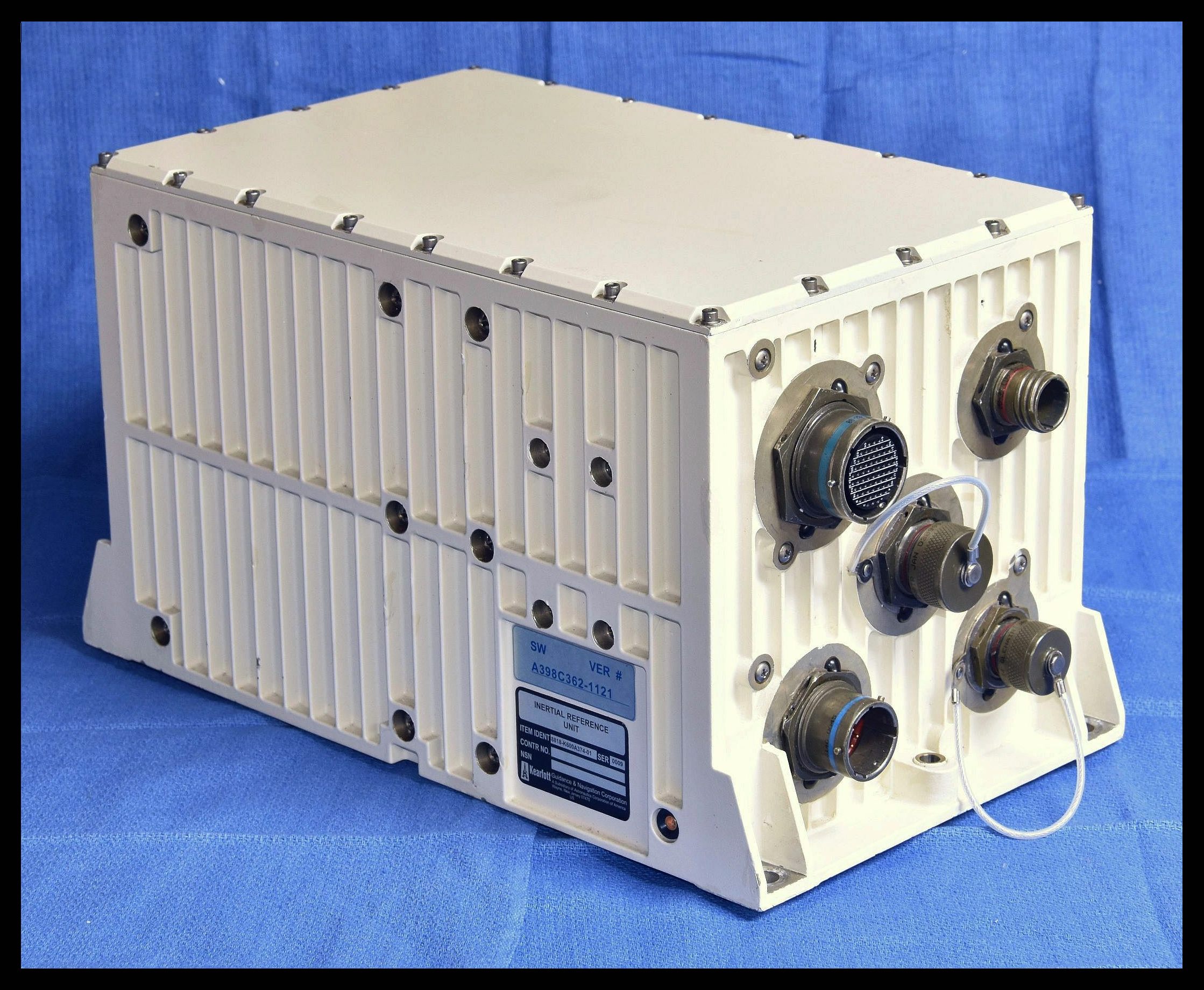
This is a complete system, probably intended for "Sea Navigation" - e.g., in submarines, larger UAVs, and the like that have degrees of freedom similar to those of an aircraft. But for ships, only 2 of the 3 axes would be useful, except perhaps in a tsunami and/or after sinking. ;-) Exactly what the difference is compared to "Land Nav" systems is probably more in the interfaces and other capabilities than the specific hardware and functions. The primary physical diffference appears to be of the paint color in the Kearfott brochures: Land Navs are black; Sea Navs are biege. I suppose that black doesn't show dust and dirt like a light color would. ;-)
Kearfott IRU from left to right: Exterior, Interior Labeled, Inertial Sensor Assembly Platform "ISAP" and its Major Components (MRLG PCB, MRLG Block, and Accelerometers), MRLG Block Labeled, MRLG Block Larger than Life
The Ring Laser Gyros (RLGs) in this IRU are interesting because all three axes are fabricated in a very compact monolithic block of special low expansion glass or ceramic, henceforth referred to as the "MRLG Block" or just "RLG Block". (The accelerometers are totally separate.) At present not much else is known about the overall IRU other than that the RLGs do light up, at least briefly when power is applied. The rectangular portion of the IRU case is 10-15/16" (L) x 6-7/8" (W) x 7" (H). Including the extensions at the ends with the mounting holes and connectors, the length increases to 12-1/2 inches. Its weight is around 14 pounds. For reference relating to what follows, the dimensions of the MRLG block itself - the 'heart' - are less than 2-1/2" across x 2-1/2" tall and it weighs under 8 ounces. For much more information on this IMU, go to Sam's Laser FAQ: Kearfott K600A374-01 IMU with Monolithic Block Triple RLG.
Note that most of the photos here and in the Web Albums below have the MRLG Block inverted compared to how it is mounted within the cylindrical ISAP housing in the IRU. It's more photogenic that way and the photons don't care. But for this reason, some of the terminology like the designation for the "Base" of the ISAP Housing (which is really at the top) may be a bit confusing. Sorry. ;-)
Kearfott Inertial Reference Unit K600A374-01 #1
The photos in the first Web Album are courtesy of Ismael Tremblay, who was the first person I knew to have acquired one of these. His photos are a bit more free-form than those of mine that follow. ;-)
Web Album: 25 Photos
Kearfott Inertial Reference Unit K600A374-01 #2 IRU #2 is mine and is believed to be identical to #1. In fact, their serial numbers differ by only 5. ;-) However, rather than disassembling the RLG Block of #2, Ismael Tremblay kindly loaned me his RLG Block for the photo shoot. So everything up until the clothes come off the RLG Block are of mine while the first set of naked photos are of his unit. But those following the photo of the poor prone ISAP housing which had been totally abused (outside at least including butchered cut cables) are of a 3rd MRLG Block and was thus perfect for more extensive disassembly and powering stand-alone. Additional chants and incantations to the gods of abused lasers were not needed and no one shall know. ;-)
But before we get to the good stuff ;-), here are some short videos of what happens with the RLG Block when the IRU is powered. Click on the small image to see the corresponding video.
Overall Setup for Glowing #1 ISAP RLG Block using IRU #2 Power Supply (left) and Four Boring Closeup Videos (Right)
These videos show the naked RLG Block from IRU #1 tethered to the power supply and electronics from IRU #2. Minor rearrangement and camera angle variations similar to the next three are used for all the powered photos in the first part of the Web Album, below. The right-most photo has the RLG Block oriented in approximate agreement with the schematic derived from the Kearfott patent. However, even with the thing in-hand and powered, it's virtually impossible to figure out the discharge and beam paths due to the contoured exterior of the block and distortion of the interior. The snapping sounds near the beginning and end of the videos are from the outlet strip power switch - on and off. Around the mid-point of the video, the RLG Block glows brightly three times in succession accompanied by a continuous audible whine (likely from the dither PZT). This behavior is 100 percent repeatable and IRUs #1 and #2 do exactly the same thing, so it's very likely a feature, not a bug. The assumption is that there needs to be some handshaking with whatever the IRU is connected to for it to remain active. The power LED does stay lit but that is the only remaining sign of life. So these videos get really boring in almost no time at all.....
And finally, now for the good stuff. ;-) The photos in this Web Album were taken over the course of several months starting with overall shots of IRU #2 and its major components, followed by Ismael's MRLG Block #1 (some powered from IRU #2), and then the naked RLG Block from ISAP #3 lit up using a custom power supply.
Web Album: 176 Photos
- Overall views (Front1, Right1, Front_Right1, Right1, Back_Right1, Back1,
Back_Left1, Left1, Front_Left1): These are virtually identical in
appaerance to the sample on the Kearfott Website in the year 2025 under
"Sea Nav IMUs".
- Connectors1 and Connector1-5: These are the panel with the
five military-style circular connectors and closeups:
- J1 (66 pins): Control / Signal / Information.
- J2 (15 pins): Power input. 28 VDC nominal, 30 W max. 24 VDC OK. +Vin: Pins A,B; -Vin: Pins M,N. Case GND: Pin P. No other pins used.
- J3 (13 pins): ????
- J4 (22 pins): ????
- J5 (13 pins): ????
(J3 and J5 have the same pin configuration but are keyed differently.)
- Label1: This has both the numbers as described above. This unit
is SER 0009
- Indicator1, Lit1. amd Indicator2: This is also visible in the lower
right corner of the Label photo. Originally I thought it was some sort of
fancy optical sensor because it does NOT look like a photodiode or LED. But
the mystery has been mostly solved after powering the unit multiple times for
the photo shoots and actually paying attention to what it does, which would
appear to simply be a high priced mil-spec LED in a hermetic package no doubt
costing the U.S. Taxpayer BIG BUCKS. It turns on bright green a couple
seconds after power is applied to the IRU. Whether it is simply a fancy
Power LED or something more sophisticated is not known.
And in the "well that's interesting department", SER 0003 - which is identical in every other respect to this one (SER 0009) including all the labeling - has what looks like a green dome over the pricey hermetic LED as shown in the 3rd pic from SER 0003. Perhaps it fell off of SER 0009. Or it was a cost saving of 0.00001 cent. ;-)
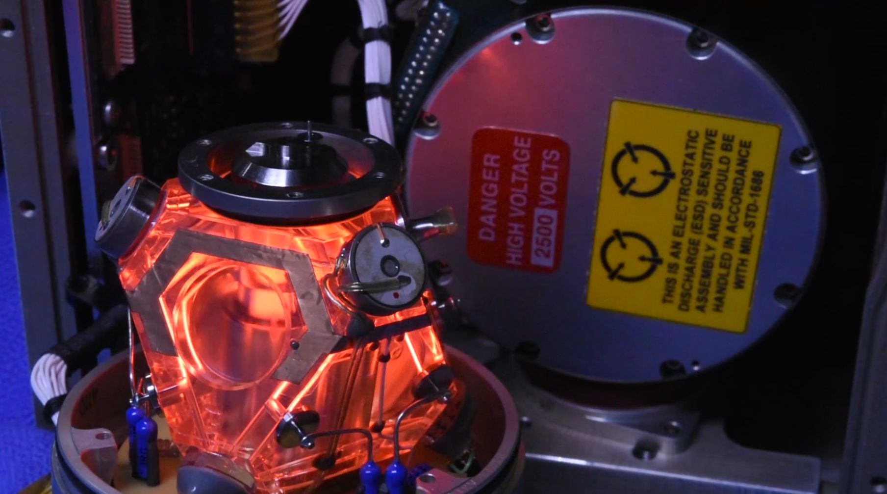
- Caution_Label1: Like we didn't know. ;-)
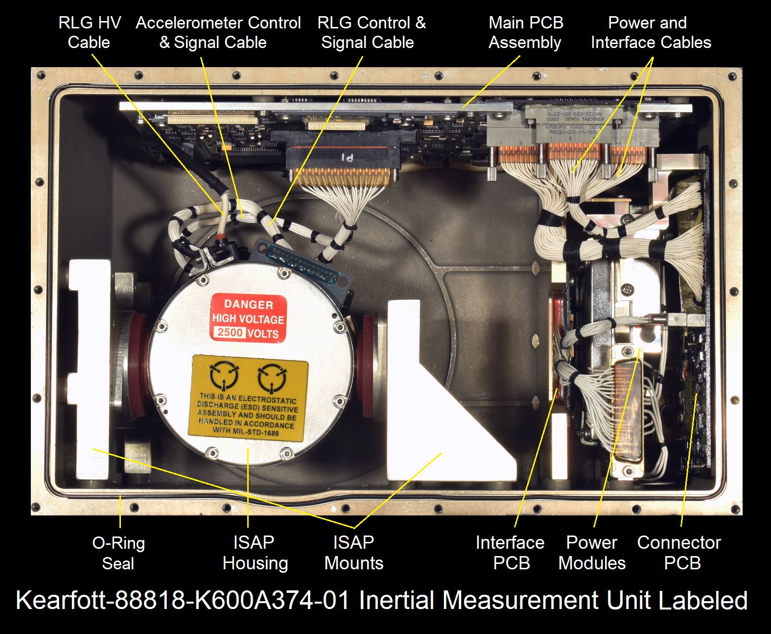
- Inside_Top1: This is what greets you after removing the cover. It's
a very clean layout with only 3 or 4 major subassemblies (depending on how
they are counted): Main PCB Assembly (top of photo, mostly hidden),
"Inertial Sensor Assembly, Platform" (ISAP, the round can on elastomer mounts,
lower left) - the heart with the ring laser gyro block and accelerometers;
and the power input, conditioning, and interface modules (lower right).
- Main_PCB_in_Situ1: What's visible is the top PCB; a similar size
board is mounted on the other side of the aluminum frame.
- Connector_PCB_in_Situ1: At least for some of the connectors.
- Top_Main_PCB1: Some LSI parts but mostly smaller ICs. The
black polka-dot rectangular affair at the right is the high voltage power
supply for the RLGs and possibly the dither PZT.
- Bottom_Main_PCB1: More chips including a Texas Instruments TMS320
DSP. I would guess that the black painted-over 32 pin packages contain the
firmware. ;-)
- Power_Connector_Module_Inside1: This is what is behind J2. It
shows the very simple but almost impossible to follow wiring due to the
use of all white insulation. ;-)
- Power_Filters1: These appear to be RFI-type filters for the
input power. (Look up their Martek part numbers!) Also visible is the Power
Connector Module.
- DC Power_Converter1: This is another readily identifiable Martek
module. It is a DC-DC converter that takes 28 VDC (nominal) and provides
+5 VDC and ±15 VDC for all the electronics. The spec is actually
14 to 40 V in, so fortunately it will run happily off 24 VDC, which is
a lot more common for powering on the bench with a fixed supply. ;-)
- Interface_PCB1: Function of this PCB is unknown but it has a bunch
of opto-isolators on it so it must have something to do with interacing in
a nasty electrical environment.
- RLG_HV_Connector1: This is really just a white wire with high
voltage insulation and a female contact secured with a black plastic cap
for the HeNe lasers inside the RLG block and possibly the dither PZT.
It has approximately -600 VDC on it with respect to the case starting
a few seconds after the IRU is powered. There is enough high quality
capacitance somewhere such that sufficient charge may still be present
hours after powering down to result in a mildly shocking
experience. ;-)
- ISAP_in_Situ1: Another view.
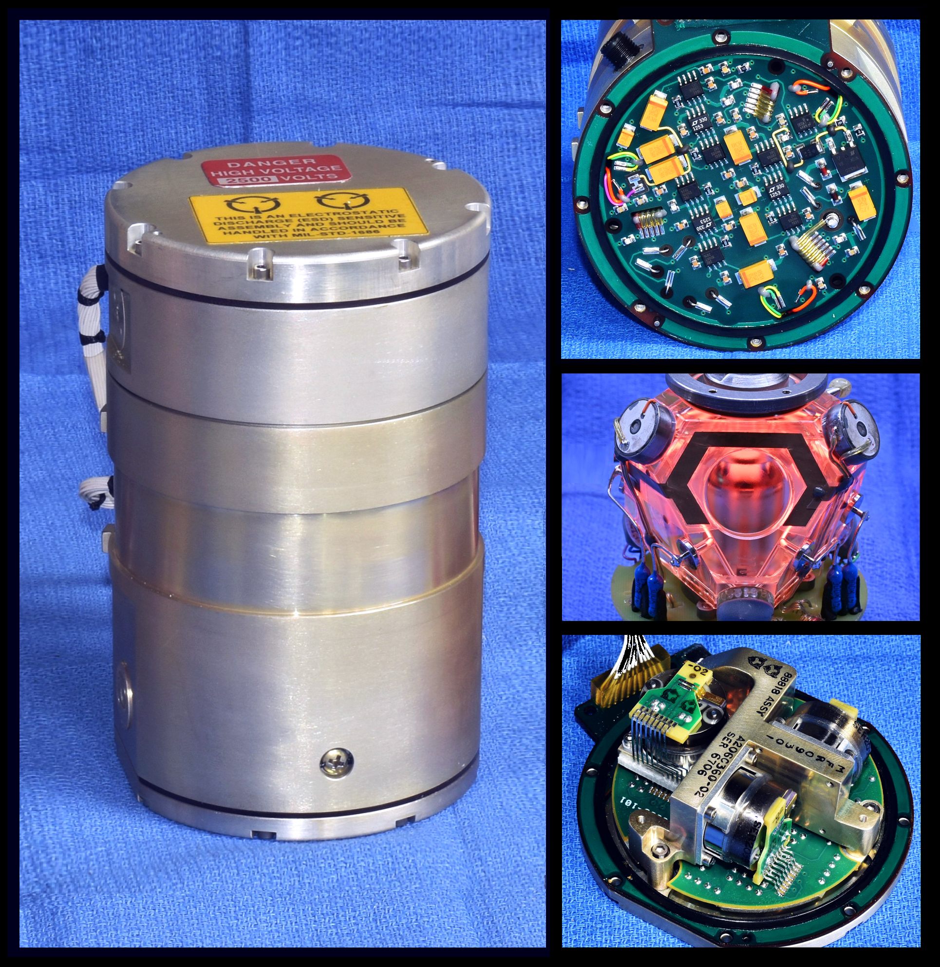
- ISAP_with_Mounts1: Front, Right Side, Back, Left Side, Top,
Top_Label, Bottom. The upper cable is for the RLG, the lower cable is
for the accelerometers. The +HV socket for the RLG is also visible.
- ISAP_Label: And ISAP S/N 670. ;-)
- Inertial_Measurement_Unit_Labeled1: And an interior
view with major assemblies annotated. ;-)
- ISAP_Housing_Mounts_Shroud1: Exposing the cylinder with the RLG
block and accelerometers.
- ISAP_Shroud1: The purpose of the Shroud is not entirely obvious as
it is not structural. But it is made of a thin soft ferrous material which
is perhaps Mu-metal, and thus may be a serving as a magnetic shield. It is
conceivable that even weak magnetic fields could affect the behavior of
the lasers in the RLG at the margins of precision, even resulting in
Zeeman splitting. If that isn't its function, its purpose must be to
make disassembly more annoying. ;( ;-)
- ISAP_Shroud_Label1: The wording of the label on the shroud is
strange (and probably unrelated to the shroud itself): "KEARFOTT
CORPORATION IS THE INITIAL TRANSFERER OF THIS PRODUCT, WHICH CONTAINS
THORIUM LICENSED UNDER 10 CFR 40.13(c)(i)(ii)". It's even stranger looking
up the definition of 10 CFR 40.13. ;-) 10 CFR 40 is part of the
"Code of Federal Regulations" dealing with nuclear
energy. ;-) Part 13 states that the company is
exempt from regulations because there is very little of the stuff present.
Thorium is a weak Alpha emitter so a trace amount may have been placed inside
the RLG block to assist starting of the HeNe lasers. Any Alpha particles
would be totally blocked by the block (no pun intended intentionally)
so no need for your Gieger counter. ;-)
- ISAP_RLG_PCB_Top1 and Close1: The RLG monolithic block is below this
PCB. The wires in the 3 ribbon cables (5, 6, 7 wires each) and 3 sets of
individual orange, yellow, and green wires need to be carefully unsoldered
to remove the PCB. That's a total of 27 wires and they are a lot thinner
and closer together than they appear
in the photos. In fact everything in the "can" (which is around 8 cm or
just over 3-1/8 inches in diameter) is actually much smaller than
it appears in the photos. ;( ;-) Detaching (and re-attaching) the wires
requires a steady hand, super fine tip soldering iron, and Mark II upgraded
eyeballs (or a good magnifier or microscope).
- ISAP_Accelerometers_with_PCB1 and Close1: The three accelerometer
units are attached to a metal frame and wired to their respective PCBs.
- ISAP_Accelerometer_Interface_ICs1 and Close1: A fancy part for
each one. ;-) This may be custom as the only hits via a Web search return
info on an older Kearfott IMU.
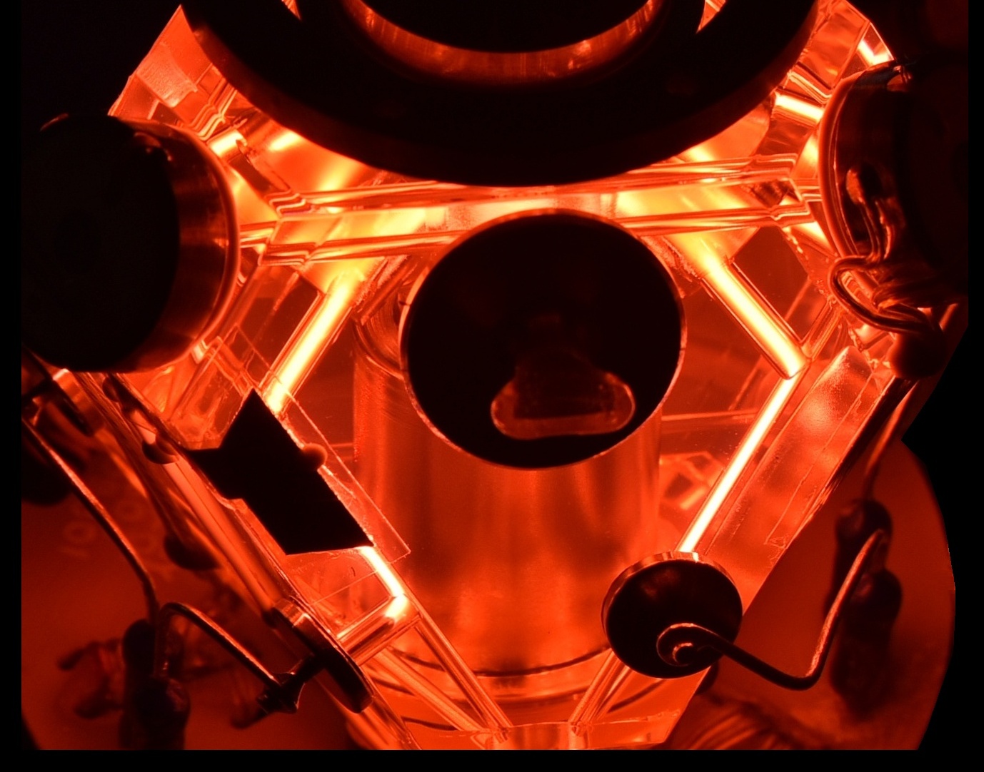
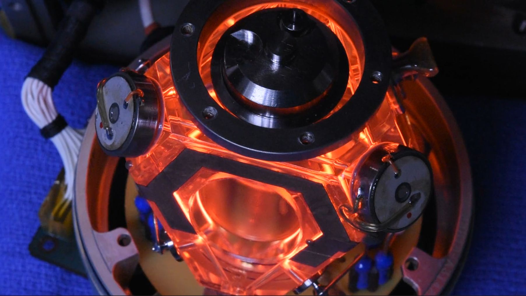
- ISAP_RLG_Block_in_Situ1: The visible portion of the RLG block
exposed when the accelerometer assembly is removed. Three of the six
mirrors are visible with their PZTs for cavity length control.
The purpose of the what appears to be Home Depot Fiberglas foam is not
known. It's very soft and fluffy and not
likely to provide much damping or thermal isolation.
- ISAP_RLG_Block_Insulation1: After removal. I hope the specific
locations of each clump were recorded. ;-)
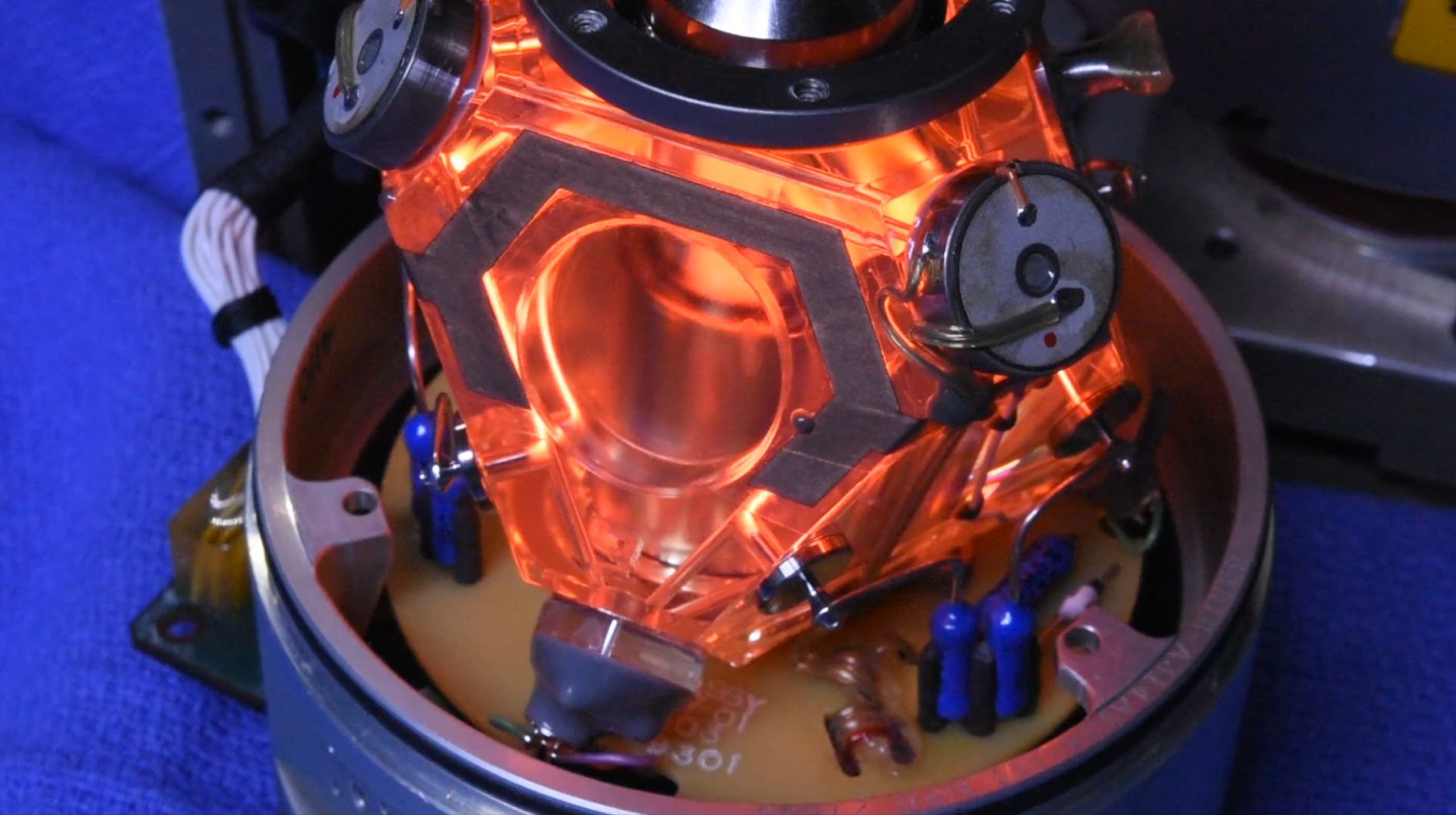
- ISAP_RLG_Block_in_Situ2: And with the foam removed. When the
RLG lasers are powered there is around -500 VDC on the central pillar as
well as the small test-point at the 1'oclock position, which is actually
connected directly to it. Go figure. ;-) However, this is NOT the common
cathode for the 6 discharges, but separated from it by a significant gap
within the block which probably serves as a HeNe gas reservoir. So there
is a voltage difference of around 100 V (for a total of -600 V) on the
actual cathode at the other end of the RLG block and a faint glow can
be seen in the space between them. Assuming the material for both
parts of the pillar is the same, either could really be used for
the cathode connection.
I wanted to take photos of RLG Block powered in situ but for some reason, neither the RLG discharges or PZT drive will come on with the cover in place even if not attached. There is just a brief faint "weep" and it then apparently aborts. ;( ;-)
- ISAP_RLG_Block_Cover1: Removing this is more than a matter of
three screws. There are 27 teeny wires that need to be carefully unsoldered.
And everything is must smaller and more closely spaced than it appears in
the photos.
The overall dimensions of the cover cylinder are 3-1/4 inches in diameter (not including the small protrusions) and 5-3/4 inches tall. The RLG Block itself is around 2-1/2 inches at its maximum width. So this is really so much smaller than it appears in the photos and videos! ;-)
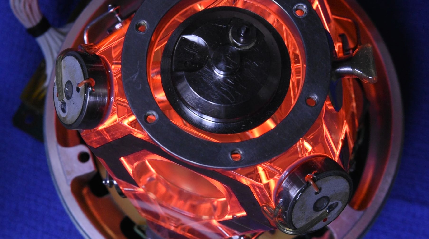
- ISAP_RLG_Block_Top1-2: Two views almost straight down. Note that
when inside the IRU, the MRLG block is actually inverted from how it is
shown here and in most of the subsequent photos. The base is at the top
of the housing.
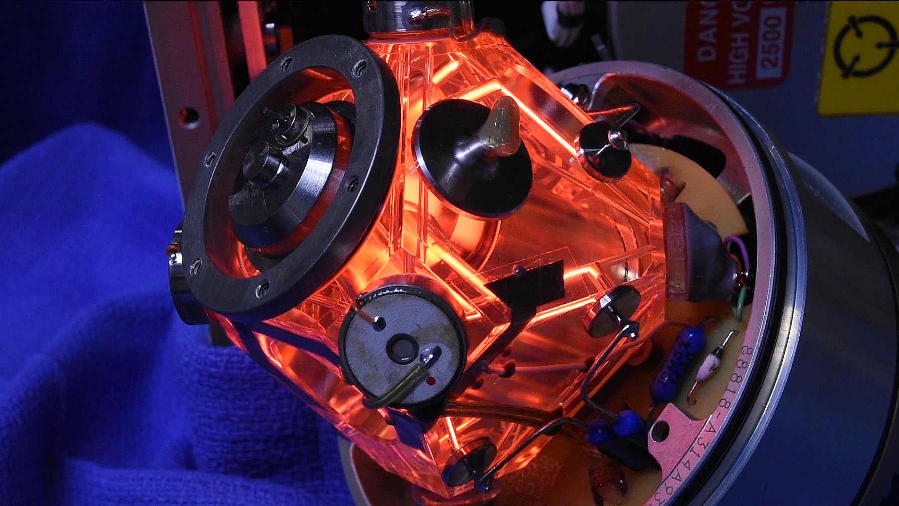
- ISAP_RLG_Block_Down1-5: Six Views at roughly a 45 degree angle.
- ISAP_RLG_Block_Side1-6: Six views at roughly a 15 degree angle.
- ISAP_RLG_Block_Close1-5: Five closeup views of the interior
attempting to show details of the pillar area, but the block gets in the
way distorting everything within it.
Two of these shots show what appear to be coils of magnet wire near the bottom, specific purpose unknown, though a guess would be that they are part of the pulsed starter for the six HeNe laser discharges. With a supply voltage of 600 V and "tube" discharge voltage of 500 V, the current would be around 0.33 mA though the 300K ohm ballast resistor for each discharge path, which is consistent with measurements made on other similar RLGs. There is probably no actual current regulator, only a transistor or MOSFET switch to disable the discharges when the RLGs are not running since the 600 VDC supply remains on constantly.
- ISAP_RLG_Block_Not_Powered, Powered, and Dark_Powered: Several
sets of photos from various orientations and distances showing the RLG Block
in room lighting, with the discharge powered, and the same in the dark.
However, being tethered to the HV and RLG cables severely limits options for
creative photo composition. ;-)
The first set of three shots shows the overall setup for taking these photos with the naked ISAP RLG Block next to its clothed buddy inside the IMU.
Since this IRU is not connected to anything except power, it does not stay on for more than a few seconds. This is not thought to be a fault since unit #1 does the same thing. So it's a feature, not a bug. At least that is the assumption: Its microbrain expects some sort of hand-shaking or acknowledgement and quits when this does not occur. Further, the RLG Block is only powered three (3) times for a second or so and then shuts off until the next power cycle. So the photos of the RLG Block with the discharge glowing required applying power to the IMU with the camera already focused and its shutter mode set to "Repeat". ;-)
- ISAP_RLG_Block_Central_Pillar1: This is in two parts - The bottom
section is the common cathode for the HeNe discharge paths
with a gap between it and the top section. The bottom section receives
approximately -600 V directly from the HV power supply but there is only
around -500 V with respect to the IMU case on both the top of the top
section of the pillar itself and the little test-point at the 1 o'clock
position when the lasers are lit. (The test-point is electrically
connected to the pillar even though it looks like it is separate, strange!)
So, ~100 V is lost somewhere, likely due to the ionization voltage of the gap.
What is not known is whether there is an additional positive voltage applied
via the anode circuit for regulation. It isn't obvious where that goes
on the RLG PCB. It may just be GND.
- ISAP_RLG_Block_Ballast1: The blue resistors standing up (each
100K ohms) are the main ballast for 2 of the 6 HeNe discharges.
Their common point is connected
to the other two pairs. The blue 10M ohm resistor laying down along with
the a HV diode are part of the starter which pulses the metal ribbons
visible in most views of the RLG block to initiate the discharges via
the thin white wire. It is near the ballast resistors but has no
coonnection to or association with them.
- ISAP_RLG_Block_Tip-off1: This is where the air gets sucked out
and the HeNe gas mixture gets sucked in. ;-) Unlike some other RLG designs,
it is NOT a cathode. The glob covering it is primarily to protect fragile
humans as the metal is very sharp after it is pinched off with several tons
of force forming a cold weld. The large disk ia probably frit-sealed to
the RLG block to achieve permanent gas integrity.
- ISAP_RLG_Block_Mirror+PZT1-3: These are the three
mirrors that are micro-positioned for cavity length control. These shots are in no
particular order. Based on what is visible, it is *believed* that each mirror is
coated on a substrate that is
attached to the surrounding cylinder by a very thin section so that it
can move the required micron or so. Each PZT
consists of a pair of thin Lead Zirconate Titanate (PZT!)
disks with a shared metal plate between them. One phase of the
drive signal is applied to the top (visible disk) and bottom disk (via the
orange insulated wire
that passes through a hole in the side of the cylinder) with the other phase going
to the common plate soldered to the cylinder itself. That's the only
scheme that makes sense based on what is visible and nebulous information via a Web
search.
- ISAP_RLG_Block_Mirror+Detector1-3: These are closeups of the
three mirrors which have the interferometers combining the clockwise and
counter-clockwise beams and detectors for each of the three axes. They
are in no particular order.
- ISAP_RLG_Block_Window1: This shows the clear more-or-less planar
port hole showing the glow in the space between the cathode and discharge
paths.
- ISAP_RLG_Block_Anodes1: This shows two of the 6 anodes. Note how
the snode pin extends almost into the discharge path. Like the tip-off, these
are also probably frit-sealed.
- ISAP_RLG_Block_Schematic1: This diagram is derived from the
Kearfott patent and shows the arrangement of the mirrors and beam paths
inside the RLG Block. The leg length of the discharge paths in the
RLG Block is between 1.5 and 1.75 inches - it's difficult to measure
precisely or even if the geometry is a precise square. With 4 legs,
the result is a total ring cavity length of between 6 and 7 inches
for an enclosed area of between 2.25 and 3.0625 square inches.
Therefore, the sensitivity is higher than that of the Honeywell GG1320,
which has a two inch leg length but only 3 legs for a 6 inch ring cavity
length with an enclosed area of 1.73 square inches..
- Kearfott-K600A374-01_ISAP_RLG_Block_Diagram_with_Parts_Labeled1: This
shows what is inside the XY, YZ, and XZ Mirror/Detector and Mirror PZT
assemblies. Errors are possible since some of the details were inferred based
on diagrams of other RLGs and wild guesses. ;-) More details would require
taking this one to bits and that isn't going to happen for a while at least.
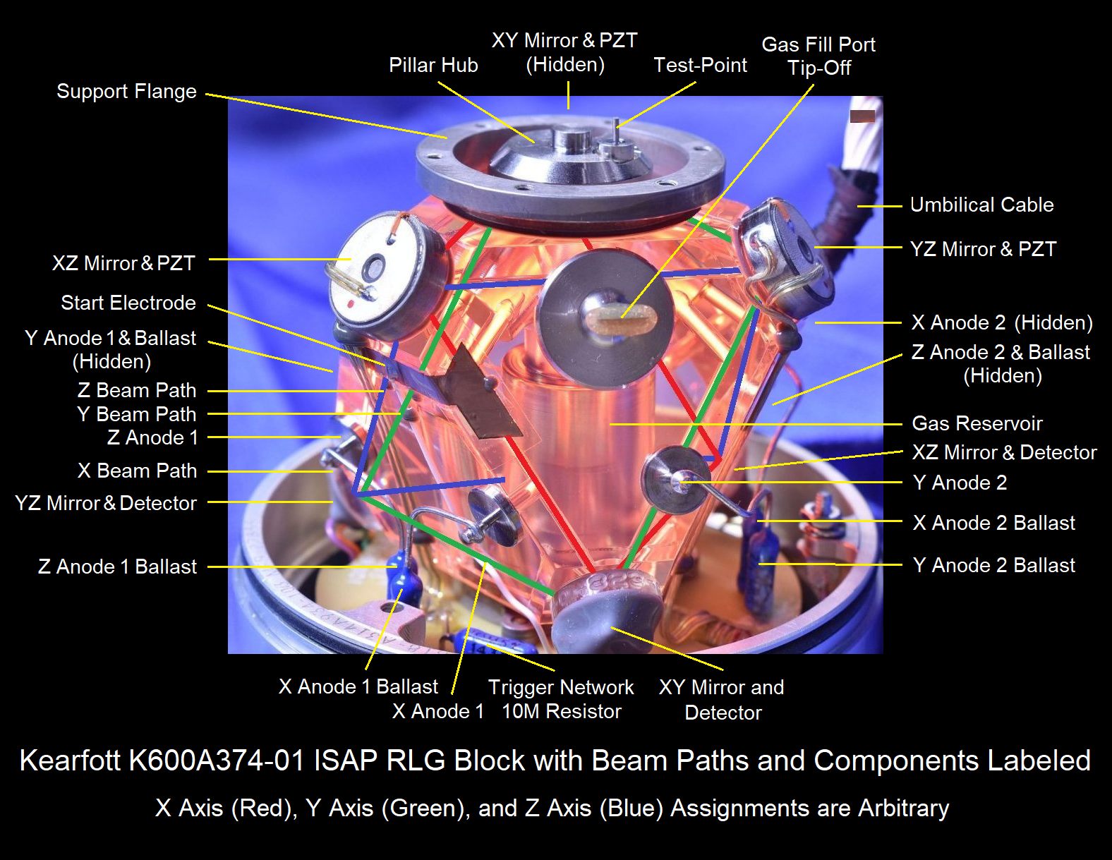
- ISAP_RLG_Block_with_Beam_Paths_and_Components_Labeled1: Each ring cavity is
color-coded to more clearly show how it is embedded and oriented in the RLG block
along with labels identifying the major components. Sorry, all the beams are
really 633 nm red. ;-)
Each ring or beam path is a tilted square that surrounds the central pillar. It is very difficult to visualize the relationships in the actual device in part due to the distortion caused by the block, perspective when viewing the actual block in any photo of it, and the (incorrect) assumption that the ring paths must be close to the outer surfaces. There may be errors and it has nothing to with AI! ;-)
- ISAP_RLG_Block_Oriented_Similar_to_Schematic1: The RLG block was rotated so that the locations of the mirrors are very approximately like those in the schematic. More or less. ;-)
The next series of photos is of an orphan ISAP with RLG. Apparently, it had be forceably removed from its IRU and mounts against its will, thus the cut wires and mangled edge of the RLG PCB.
- ISAP_Housing_Hatchet_Job1: This is how it
appeared just after removing the Mu-Metal shroud and the remains of some
cable clamps. The wires cut, or more accurately hacked off. Poor thing.
- ISAP_Housing_Unclothed1: Another similar view
but standing up and hiding the poor cables. ;-)
- ISAP_Housing_Top1: and
ISAP_Housing_Top2: are pretty much identical to
the unit above. And the SNs of the IRUs differ by only 3 or 4.
- ISAP_Housing_Bottom1: For some reason the label on this one
differs from the other. It should be the same internally.
- ISAP_RLG_PCB_Top_Close2: The is virtually
identical to ISAP_RLG_PCB_Top_Close1, above, except
possibly for some wire colors.
- ISAP_RLG_Block_in_Situ3: Can you spot the
difference between this one and ISAP_RLG_Block_in_Situ2,
above? ;-)
- ISAP_RLG_PCB_Removed_Top1: The
RLG PCB had the three ribbon cables and 3 sets of discrete wires
un-soldered so it can be completely removed.
- ISAP_RLG_PCB_Removed_Bottom1: The 2 black cylinders are
transformers. One is a pulse transformer for starting the HeNe
discharges but its exact specifications are not known as it appears
to be a special part with the Kearfott 88818 CAGE code. The other is
a standard commercial part - a PICO S21670 power transformer spec'd
at 115 V input, 12.8 VCT output, and a frequency of 400 Hz. Its 6.4
V output windings are connected in parallel here. It is used in
reverse for driving the PZTs.
- ISAP_RLG_Block_PCB1: This is the cylinder base with the 3 PZT
that dither entire RLG block attached to the struts. The green, blue, and
violet wires are for the detectors; the detached discrete colored wires
are for the PZTs; and the HV cable goes directly to the center post, which
is attached to the common cathode for all 6 discharge paths.
- ISAP_Housing_Top_Cover_Top1-2, Bottom1-2: The
housing covers including, apparently, their part numbers, perhaps.
- ISAP_Empty_Housing Top1, Top2, Bottom1, and
Bottom2: These show the empty shell. ;-)
- ISAP_RLG_Block_in_Housing_Base1:: This is
similar to ISAP_RLG_Block_Down3, above.
- ISAP_Base_Top1-2, Bottom1, and Side1: The HV connector
with its cable attaches using a stud and nut to the center post and cathode
of all 6 discharge paths. The 3 PZT actuators are glued to the 3 struts via
the 3 sets of orange, yellow, and green wires.
- ISAP_Base_PZT_Close1: Shows details of the actual PZT with
its 3 electrodes. The large one is probably for drive with the others
for feedback, or something. ;-)
- ISAP_RLG_Block_Removed_Top1: View from above without housing base.
- ISAP_RLG_Block_Removed_Side1-6: These views
of the naked ;-) RLG block are similar to those in
ISAP_RLG_Block_Side1-6 except for the lack of the housing base.
- ISAP_RLG_Block_Removed_Bottom1-4: The 6
thick bare wire leads are the 6 100K ohm ballast resistors, which are
all shorted together on this PCB. The 3 sets of green, blue, and violet
wires go to the 3 detectors. The poor abused ribbon cables ;-) include
the positive anode voltage (which may simply be ground) and PZT signals for
the mirrors to fine tune or dither cavity length, among others as yet to
be identified.
- ISAP_RLG_Block_First_Light1: After removing
the base, this is the first time any of the discharge paths have been lit
from an external HeNe laser power supply. Electrically, all 6 discharge
paths are in parallel, only isolated by 100K ohm ballast resistors. So if
driven by a constant current power supply like one for a normal (single) HeNe
laser, the first discharge to strike will pull down the voltage
on all the others preventing them from starting. And indeed only a
single discharge path is lit in the photo with a current of around
0.4 mA. In the IRU, the controller applies a pulse via a HV diode
in parallel with a 10M ohm resistor to the metallic strips visible
in most of the RLG photos. So it's like a xenon flashlamp trigger.
- ISAP_RLG_PCB_PZT_Transformer1: This is a standard power
transformer made by PICO with specs of 115 V input to dual 6.4 V outputs
at 400 Hz. It is used in reverse to provide for the high frequency
drive to the PZTs. The yellow and green wires to all 3 PZTs are
connected directly across its primary (now secondary) winding.
The orange wires are connected together but go somewhere else, probably
some type of sense signal.
- ISAP_RLG_PCB_Start_Transformer1, ISAP_RLG_PCB_Start_Post1, and
ISAP_RLG_Block_Removed_Trigger1: These provide the starting pulse
to initiate all 6 discharge paths. The black cylinder is the trigger
transformer mounted on the underside of the RLG PCB (see photo
above). The 7 conductor ribbon cable including trigger wire passes
through the slot on its way to the RLG Block PCB. The 10M ohm
resistor and HV diode laying down connect between the trigger wire
soldered to the post on the RLG PCB and the white wire which runs to
the copper strips (trigger / start electrodes) glued to the RLG block
in proximity to the 6 discharge paths.
- Kearfott-K600A374-01_ISAP_RLG_Block_PZT_Close1,2,3: Closeups of the PZTs
behind the mirrors to tune the cavity lengths. See the information above on how
they are connected.
- Kearfott-K600A374-01_ISAP_RLG_Block_Detector_Close1,2,3: Closeups of the
fringe detectors for the X, Y, and Z axes. Corner prisms are assumed to be
covered with the gray rubber.
- Kearfott-K600A374-01_ISAP_RLG_Anode_Close1: Details of one of the anodes.
- Kearfott-K600A374-01_ISAP_RLG_Block_Tip-Off_Close1: In all its glory. ;-)
- Kearfott-K600A374-01_ISAP_RLG_Laser_Start_Network1: The 10M ohm resistor and
HV diode in parallel are in series with the trigger transformer to the start tape
stuck to the RLG block more or less adjacent to the discharge paths.
- ISAP_RLG_Block+External_Power_Supply1: This
shows the RLG block on an acrylic stand running off a custom stand-alone power
supply constructed on a solderless breadboard. The input is 12 VDC which is
boosted to 600 to 1,200 V by the inverter transformer (center of circuit).
The micro-switch in the lower left discharges a capacitor into the trigger
transformer (right side of circuit).
- ISAP_RLG_Block_External_Power1-6: Shots of the RLG block on external power.
- ISAP_RLG_Block_External_Power_Close1-6: And closeups.
- ISAP_RLG_Block+External_Power_Supply2: The
power supply has been transferred to a Perf. board to be more permanent.
I was considering designing a PCB for the power supply but the market would
be quite small unless Kearfott was interested in using the design for testing.
Then it would be a total of 3. ;-)
- ISAP_RLG_Block_Size_Comparison1-2: To appreciate how small the entire RLG block really is, these show a bog standard 2 inch Acrylic cube and bog standard regulation size baseball beside it. In fact, the entire block itself would fit comfortably inside the baseball with room to spare, though the tips of the "attachments" might poke through the cover. ;-)