The vacuum system serves three functions:
By the standards of the vacuum industry, our requirements are modest and are generally called a "medium" vacuum - not the sort of situation where every last "particle" of air needs to be removed but still 1/100th to 1/10,000th of normal atmospheric pressure. These are not generally considered a "high" vacuum (though that's what may be found in catalog listings for the types of mechanical vacuum pumps and gauges that are used) but they are still not the sort of thing you come across in daily life. However, to be able to fill the laser with (mostly) pure gases, it is desirable for the vacuum system to go substantially lower in pressure than that at which the laser operates. And this includes the upper end of the high vacuum range - down to perhaps 1,000,000th of normal atmospheric pressure.
I am gradually putting together a vacuum system (or at least acquiring parts!) and may have an interest in your cast-off or excess vacuum equipment (relatively small items, not complete ion beam machines!) or accessories. Please see: Sam's Classified Page, "Wanted to Acquire" near the end, if you have anything available.
These include:
Try to locate "Procedures in Experimental Physics" by John Strong (who wrote many of the SciAm Amateur Scientist articles). In particular, see Chapter 3: Technique of High Vacuum.
"I highly recommend a really nifty book also from the Society of Amateur Scientists. It's one of the old reprints that Lindsay books does in cooperation with SAS called "Procedures in Experimental Physics".
The vacuum section is EXCELLENT for the science hacker. Everything from building vacuum gauges from vacuum tubes to desktop thin film sputtering to CVD coatings to making your own diffusion pumps from available materials.
The earth is covered with a vast ocean of air. Despite common experiences, even air has mass and mass implies weight. We know it has volume or else your automobile would have a real problem with flat tires. Most of the volume (the contribution from the volume of the the protons, neutrons, and electrons in the atoms are negligible but not precisely zero) results from the constant motion of the molecules (in air or other gas) bouncing against each-another due to their thermal motion. This also keeps the air in a gaseous state. At really low temperatures, the motion is reduced resulting in liquid and solid phases of even air. At exactly absolute zero (0 °K or -459 °F or -273 °C) all motion ceases. However, even then most of the volume of the frozen air is still empty space - but that is another story.
At sea level under average conditions, the column (actually an inverted truncated pyramid if you want to be strictly correct) of air above 1 square inch of area would weigh 14.7 pounds if you could capture, compress, and package them and plop them down on a delicatessen scale! As you move away from the earth, this 'column' of air becomes increasingly rarified approaching a prefect vacuum at 50 miles or so - else low earth orbit satellites would not stay up very long due to air friction.
It turns out that a column of mercury with an area of 1 square inch and 29.92 inches (760 mm) high weighs exactly 14.7 pounds as well (what a coincidence, huh?). So, if you take a closed-end tube a little more than 30 inches long, fill it with mercury, and invert it in a pool of mercury, the pressure of the surrounding air will be able to support a column of mercury 30 inches high. The space above the mercury will be a decent vacuum. You have made a mercury barometer. (Strictly speaking, there will be mercury vapor in that space but it won't affect the height by much.)
If you were to take this barometer and place it inside a vacuum vessel and start up the pump, the column would go down until at the point of a perfect vacuum (not achievable but close), it would be precisely level with the surrounding pool of mercury.
Note that the diameter of the tube doesn't matter - wider implies a heavier column of mercury but the area of the air acting on the column changes by the same factor. In fact, it can have pretty much any convoluted shape you want (except that if portions are too thin, surface tension becomes a factor) as long as it is sealed and totally filled with mercury. Why this is so is left as an exercise for the student!
The corresponding height of 1 atmosphere for water is about 34 feet - a column of water with a cross sectional area of 1 inch and height of 34 feet weighs 14.7 pounds. This also means that for a diver, the water pressure increases by 1 atm for each 34 feet of depth. Thus it is not surprising that there are significant problems in deep sea diving! You have to go up by MILES in air for the pressure to decrease by a substantial fraction of 1 atm but need only go down 34 feet in water to increase pressure by 1 atm!
Note that the most likely form of a pressure you are familiar with is the reading on the gauge you use when checking or filling your automobile or bicycle tires. However, this is calibrated relative to the surrounding pressure of around 1 atm. Thus, the actual pressure inside a tire will actually be 1 atm + the reading on the gauge. And you thought you had a perfect vacuum inside that flat tire when the reading was 00.0! :-)
Similarly, a vacuum can be measured relative to atmospheric pressure and this is often done for the sort of vacuum you find in an automobile engine intake manifold, vacuum hold down plate, and other familiar applications. However, these readings represent the difference between one large number (local atmospheric pressure) and another large number (your vacuum). Since weather conditions (i.e., high and low barometric pressure) can result in a variation of 1/2 inch of mercury or more, such measurements will fluctuate and aren't very useful when the absolute level of vacuum is what's important - as with gas lasers and most other scientific uses of vacuum.
Here are some units and relationships commonly found in dealing with vacuums:
If you are totally confused at this point, for a wonderful description of these units and their history, see: The Electronic Bell Jar - Pressure Units. Some high vacuum equipment suppliers have conversion charts and other related information. See for example, LDS Vacuum Products Techtips Page.
Or, here is an instant conversion chart. To convert from the units in a row on the left, multiply by the entry in the appropriate column.
             Micron   Pascal  Millibar   Torr    Inches
 ----------------------------------------------------------
  Micron       1      0.133    0.0013   0.001   1/25,000
  Pascal      7.5       1       0.01    0.0075   1/3,387
  Millibar    750      100       1       0.75    1/33.87
  Torr       1,000     133     1.33       1      1/25.4
  Inches     25,400   3,387    33.87     25.4       1
The Electronic Bell Jar Vacuum Chart provides a nice instant summary of pump types, gauges, and applications, as a function of the level of vacuum.
The following dividing lines between low, medium, high, and ultra-high vacuums are somewhat arbitrary but will be convenient for discussion:
Mountain climbers have to endure reduced pressure and above about 10,000 feet, may require (or at least benefit from) breathing equipment. Anyone who has traveled by air knows the standard speech at the beginning of each flight "....should oxygen be needed, the compartments overhead....". This would also happen above about 10,000 feet.
Astronauts on American spacecraft (at least they used to), breath unaided at a pressure of perhaps 1/5 of an atm because they breath nearly pure oxygen. Since in the normal atmosphere, oxygen is only about 18 percent of the total mixture (most of the rest is nitrogen with a little CO2 and inert gases thrown in), the resulting biological activity (and the flammability of common materials, for that matter) is about the same but there is no need to carry the approximately 80% of useless other gases and the stesses on the spacecraft structure (from the difference between the internal pressure and the vacuum outside) are reduced by 80% as well.
A low vacuum can be obtained by any number of simple mechanical means including fans and centrifugal blowers, piston and rotary pumps, aspirators, siphons, chemical combustion and other reactions (which use up the air), etc. Liquids boil at reduced temperature - often room temperature - in a modest vacuum but minimal or no precautions are needed to prepare surfaces and equipment since any outgassing is small compared to the remaining air.
I did a few very scientific experiments to determine values of two types of vacuums with which everyone is familiar:
So, next time the friendly vacuum cleaner salesperson calls, forget the oatmeal test, let them try a Bourdon tube gauge instead! :)
However, note that normal straw sucking would result in hardly any vacuum at all, only needing to raise a fluid by a few inches; 15 inches of mercury is like drinking through a straw from a container about 16 feet below you!
A medium vacuum can be achieved with a high quality mechanical pump.
A high vacuum usually typically requires a multi-step pumping scheme with a rotary mechanical pump going down to 10-2 to 10-3 Torr followed by a diffusion, turbo-molecular, or other true high vacuum pump.
Even if the final vacuum is modest (e.g., 1 to 10 Torr), being able to pump down to an ultra-high vacuum may be needed to purge the tube or whatever of contaminants with a small number of pump down/backfill cycles and minimal use of expensive gases.
In addition to mechanical and diffusion or turbo pumps, additional means are required to achieve an ultra-high vacuum including exotic ion pumps, cryo pumps, cold traps, and chemical getters. Surfaces exposed to the vacuum must be immaculate - a single fingerprint can mess things up for days!
To put a 10-9 Torr vacuum into perspective: If all of the gas molecules remaining inside a typical 17 inch monitor CRT that had been manufactured at this level of vacuum were rounded up, captured, and returned to normal atmospheric pressure, they would occupy a volume of space less than 25 um on a side - roughly 1/10th the diameter of the dot in the explanation point at the end of this sentence or half the diameter of a human hair! Yet, inside the CRT, there would still be approximately 1,000,000,000,000 gas molecules remaining for unsuspecting electrons to run into!
You may also hear the term 'hard vacuum'. I don't know if there is a precise definition for this either but I would assume that anything with a low enough pressure to behave similarly to a perfect vacuum from the normal experiences point of view would qualify. Also note that in terms of the strength required of a vacuum vessel, the difference between a vacuum of 1 Torr and 10-19 Torr is irrelevant. Why? :)
(Original chart from: Chris Chagaris (pyro@grolen.com).)
           Inches of Hg         Torr or
      Rel to 1 atm   Absolute   mm of Hg   PSI      % Vacuum     Microns
    ----------------------------------------------------------------------
         0.0          29.92      760      14.696      0.0           -
        -0.40         29.52      750      14.5        1.3           -
       -10.24         19.68      500       9.7       34.0           -
       -18.11         11.81      300       5.8       61.0           -
       -25.98          3.94      100       1.93      87.0           -
       -27.95          1.97       50       0.97      93.5           -
       -28.92          1.00       25.4     0.4912    96.6           -
       -29.52          0.40       10.0     0.193     98.7           -
       -29.88          0.04        1.0     0.0193    99.9       1000.0
       -29.916       3.94*10-3    10-1    1.93*10-3   99.99       100.0
       -29.9196      3.94*10-4    10-2    1.93*10-4   99.999       10.0
       -29.91996     3.94*10-5    10-3    1.93*10-5   99.9999       1.0
       -29.919996    3.94*10-6    10-4    1.93*10-6   99.99999      0.1
       -29.9199996   3.94*10-7    10-5    1.93*10-7   99.999999     0.01
Unless you have worked with a decent vacuum system in the past, own a HVAC service business, or just happened to pick up something that looked like a pump of some kind at a garage sale (but you weren't really sure and got lucky), you don't have the needed equipment! However, an adequate 'medium' vacuum system can be put together for less than $400 - possibly a lot less if you are determined and somewhat resourceful.
Note that it is the difference between atmospheric pressure and that of your vacuum that determines the stress on the container - whether you are pumping down to 10 Torr or 10-14 Torr is for all practical purposes irrelevant with respect to implosion risk!
If you insist on trying these bombs, cover the whole affair with some sort of shatter-proof outer cover like a thick solidly constructed Plexiglas shield but I don't recommend this in any case.
See Vacuum Pumps Suitable for Various Home-Built Lasers for diagrams of the types of vacuum pumps described below that are relevant for our purposes. See the links in the section: Vacuum Systems References, Links, Forums for more complete information on the operating principles of the pumps described below (as well as many other topics).
There are many types of mechanical pumps but they are usually based on one of two basic principles: positive displacement (perhaps these should be called negative displacement in dealing with vacuums!) and turbo-molecular:
The rotary vane type is the most common 'roughing' or 'backing' pump for use with high vacuum systems. (These terms indicate that there is another pump or pumps for actually going from a pressure of a few milliTorr to a pressure of 10-6 Torr or lower.) This is due to their relative simplicity and their ability to achieve decent performance with reasonable tolerances in the machining of their component parts. A shaft and rotor mounted off-center in a cylindrical pump chamber rotates a set of spring-loaded sliding vanes (usually 2 but possibly 4 or more). The vanes sweep a variable size volume which increases on the vacuum (intake) side and decreases on the exhaust (outlet) side. The entire mechanism is totally immersed in low vapor pressure oil. While the oil is essential for lubrication and cooling, its most critical function is to seal the spaces between the moving parts - there are no other seals between the rotor, vanes, pump chamber, and end-plates. Unlike a piston pump in which the ultimate vacuum is determined by the dead space above the piston and in the valves when the piston is at the top of its stroke, a well constructed rotary vane pump's performance is limited mainly by the back-streaming of gases from the oil. In most cases where such a pump fails to meet expectations with respect to ultimate vacuum, the cause is contamination of the oil (or the use of improper oil with a high vapor pressure) rather than a problem with the pump mechanism.
For more details and an animated graphic, see Lesker's Rotary Vane Mechanical Pump Technical Notes. (Local copy should this link decay: Copy of Lesker's Rotary Vane Mechanical Pump Technical Notes.)
A diffusion pump has no moving parts (at least at the macroscopic level). An electric heating element in its base boils a small quantity of a special 'diffusion pump oil' inside a sort of tower or percolator structure which has vents to direct the jets of oil vapor downward toward the higher pressure region (to the mechanical pump) where it condenses on the cool surfaces of the pump housing and is recycled. In in the process, air and other gas molecules are dragged along with the oil vapor. When the oil vapor condenses near the bottom (higher pressure) part of the diffusion pump, the trapped molecules are released and sucked up by the roughing pump. The actual pressure differential between the top and bottom is miniscule - only a fraction of a Torr (and the diffusion pump cannot be fired up until the roughing pump has brought the vacuum down to this level). But this is adequate to suck out most of the remaining air or other gas molecules and once it gets going, the pumping speed of a diffusion pump is quite impressive despite its passing resemblance to a coffee percolator. I know what you're thinking. :)
Diffusion pumps require cooling of their own. This is usually tap water through a coil wrapped around their exterior though some use some sort of air cooling.
For the cyclotron at my high school (right, how many high schools have atom smashers - but that is another story), we had an air-cooled glass oil diffusion pump (probably because no one else wanted it or even knew what it was). Somehow, this fragile glass structure survived all sorts of catastrophies despite being located under the main vacuum chamber situated between the pole pieces of a magnet weighing several tons and joined by a clamp-type glass and O-ring seal.......... OK, I know you're curious. See the section: The Central High School Cyclotron.
An alternative to a diffusion pump that appears distinctly low-tech (but no doubt requires very high-tech manufacturing) is the turbo-molecular pump (or "turbo pump" for short). Like the diffusion pump, the turbo pump is placed in-line with the roughing pump. A multistage turbine running at very high speed generates a compression ratio of 108 or more for outlet pressures in the range of 50 microns to 20 Torr (depending on model). These represent an alternative to diffusion and ion pumps for going 'the last mile'. Thus, an entirely mechanical high vacuum system is possible (and quite common). You probably won't see one of these at your local hamfest but one may be gathering dust in the deep dark recesses of one of your University's physics labs. They also appear on eBay from time-to-time but the final bid prices are usually quite high - typically around $1,000 for a small one - and that may not even include the controller! See the section: A Small High Vacuum System.
Turbo pumps can achieve a very clean ultra-high vacuum but due to their high speed (up to 90,000 rpm or more!), are not very tolerant of abuse or debris entering their intake port. And, at these speeds, mechanical bearings represent a maintenance item. Some use a super high quality ceramic ball bearing with special oil lubrication at one end and a passive magnetic bearing at the other end (just a couple of ceramic ring magnets, one partially inside the other). The best type use magnetic bearings throughout with the lower one usually being active feedback controlled.
For more details on turbo-molecular and another related type, the molecular drag pump, see Lesker's Turbo-Molecular and Drag Pumps Technical Notes. (Local copy should this link decay: Copy of Lesker's Turbo-Molecular and Drag Pumps Technical Notes.)
And, if you're not too squeamish, see LesioQ's Edwards Turbo Pump Disassembly Page for a dissection of one that must have lost a battle with some debris.
Though no self respecting high vacuum system would be without at least one of these high vacuum pumps, this is not really essential for most of the gas lasers under discussion especially if you have a well maintained 2 stage (or better) mechanical pump. However, if you come across a small diffusion or turbo pump (almost any size would be adequate for laser tubes) in good condition at a decent price, grab it. You can never tell when your interests might wonder in directions where a true high vacuum system would be needed.
While not generally thought of as pumps, the following perform related functions helping to rid the system of moisture and other unwanted volatile materials:
In addition to helping to achieve a high vacuum, a dryers and cold traps may also help to prevent contamination to the oil in the vacuum pumps.
(From: Steve Roberts.)
You really want an ion pump or a getter sublimation pump a.k.a. Titanium Pump (TP), or if you're really lucky, a turbo pump, although they don't hold up to abuse too well. (A debris screen should be installed on the turbo pump inlet and even with that, extreme care must be taken to assure nothing other than gas gets to the high speed turbine blades.)
Diffusion pumps are old news and outdated, they run hot, and some are huge! Depending on what is being pumped, they may need to be torn down and cleaned frequently. Small ion pumps are about $1,200 rebuilt. maybe $250 for the pump and $1,000 for the controller after rebuild, which means they are dirt cheap if you find a used one. I've seen a few diffusion pumps given away in the past few years but they really were clunkers and sensitive to contamination. Ion pumps do run out as they have a consumable material inside them that reacts with remaining gas, but they also get you a cleaner vacuum then a diffusion pump.
Ion pumps also act as a gauge by themselves, although not as accurate as a dedicated gauge. What you want is an appendage ion pump. They are small and fast for your purposes, and small enough you can lift them.
TPs use a hot titanium filament to bury gas molecules under a thin film of metal. The only thing they use up are rods which are presently about $160 for a lifetime supply. TP are more suited for large vacuum chambers, but they create a fast clean vacuum and are resistant to an amateur's mistakes.
The gauges are only about $250 for a new digital one, which is almost cheaper then buying or scrounging a used ThermoCouple (TC) gauge and these do wear out. You're better off looking for a digital capacitance manometer then an old beat up TC. (Of course I've acquired several complete TC gauges for less than $50 each complete and put one together for around $25 - the cost of the sensor - using junk parts. --- Sam)
A well maintained two-stage rotary mechanical pump (the sort of thing you find in high school physics departments. OK, perhaps except for the 'well maintained' part!) can achieve a vacuum of less than 5 milliTorr (5 microns) if conditions are favorable. However, with use and age which results mostly in oil contamination, even 100 milliTorr may be optimistic. So, if you find one of these at a garage sale (as I have), it may be necessary to at least totally drain the old oil; flush, run, and drain again; and then fill with fresh vacuum pump oil of the proper type. Just an oil change without flushing isn't quite as good but may achieve adequate performance for a pump that hasn't been abused. Proper rotary vane vacuum pump oil is available from vacuum, scientific, and laboratory supply houses as well as from refrigeration service companies. No, motor oil or 3-In-One won't do! Refrigeration service pump oil isn't what you want for a true high vacuum but is good as a flush and is certainly adequate for the CO2 and N2 lasers. It may even be available from a place like Pep Boys at all of $10 for a gallon! (But real vacuum pump oil is also available for about $10 to $15 per gallon from some suppliers like Duniway Stockroom.) Flushing the pump and replacing its oil may be the single most important thing to achieve acceptable performance. Unless the pump was abused, it will probably be all that is needed.
See the section: Rotary Vane Vacuum Pump Mainenance for more details on reviving a pump that doesn't pump very well. :)
Moisture is also a killer of oil, so using such a pump as a wet-dry vac isn't a good idea either! A "gas ballast" capability is a feature common to many rotary vane vacuum pumps. (The actual technical term is "vented exhaust valve" but "gas ballast" is what is most often found in vacuum pump descriptions.) Whatever it's called, the purpose is to introduce atmospheric pressure air into the outlet gas stream to dilute any water vapor and reduce the amount that gets dissolved back into the oil. However, the gas ballasting usually increases the base (lowest) pressure attainable by up to a factor of 10 or more depending on design so where there is an option (usually an adjustable valve), it should only be used near the beginning of a pump-down cycle and then disabled (closed). The gas ballast can also be used to help purge the oil of dissolved vapors since air bubbling through the oil will tend to pick up dissolved stuff. For most home-built lasers, this isn't an issue since there shouldn't be much water vapor to evacuate and having no gas ballast will be just fine. However, some pumps (usually HVAC types) don't provide the option of disabling the gas ballast (though there are usually ways around this). A gas ballast that is always enabled may limit high vacuum performance since as noted it can increase the lowest attainable pressure.
Small high quality rotary vane pumps may cost $1,000 or more new, perhaps $500 used but it's quite possible to find them even cheaper from auctions and other sources. See the section: Sources for Vacuum Equipment and Supplies.
CAUTION: Many of these pumps DO NOT provide an automatic means of preventing pump oil from being sucked back into the evacuated part of the system after the pump is shut off. Unless the instructions for your pump explicitly state that a "safety valve" or "automatic vent valve" or something similar is provided - and it is known to be operating correctly - the system must be isolated or vented manually to prevent the possibility of oil entering EVERYTHING including the vacuum gauge sensor heads. This will likely require a complete tear-down and cleaning to restore reasonable performance. The vacuum gauges should definitely NOT be powered up if their sensors are contaminated with oil as they may be damaged resulting in altered calibration or total destruction. Pfeiffer rotary vane pumps provide an electrically or hydraulically actuated safety valve; Welch two-stage pumps are supposed to be immune but Welch single stage pumps are not (both unconfirmed); and Precision Scientific pumps may allow much of their oil to enter the system. Don't ask me how I found out. :(
If you do pick up one of these used with original oil, replacing the oil should greatly improve its performance as all sorts of contamination can be sucked in when used to evacuate refrigeration systems and there was probably little or no maintenance ever performed on the pump itself!
Note that for no justifiable reason, HVAC service pumps tend to have really narrow inlet fittings and these should be replaced to achieve best performance for general vacuum work. This is easily accomplished if they use standard pipe threads. If not, some improvisation will be needed. I replaced the fitting on my Precision Scientific D25 look-alike which had been used for HVAC service and had a very narrow screw-on hose connector. While the original fitting was very convenient since no tools were required to change hoses, the hoses were also very narrow - about 3/16" ID - and were so contaminated with who-knows-what or leaked or something that pulling any sort of decent vacuum wasn't possible anyhow. The replacement was a brass 5/8" HB x 1/2" MPT hose barb - about $2 at the local hardware store. (For most home-built lasers, this modification really isn't essential since the required flow rates are generally not that great but it won't hurt and then you'll be all set for the future.)
The Electronic Bell Jar has a detailed article on refrigeration service pumps.
The specifications below are for Welch's belt-drive ("DuoSeal") pumps. Newer ones will always have a belt guard (some OSHA requirement I assume) but many of the older pumps do not. (Adding a belt guard is definitely advised in any case unless the pump can be permanently positioned to place the pulley-side against a wall out of harm's way - yours and the pump's.) For a given pumping speed, belt-driven pumps run slower and cooler (which increases reliability and life expectancy of both the pump and oil) and tend to be quieter than similar performance direct-drive pumps, but they are larger, heavier, and likely to vibrate more. However, should the motor need replacing for some reason on a belt-drive pump, a standard model from any number of sources or your junk corner will do. The motor in direct-drive pumps (which Welch also manufactures) may only be available from the original supplier, if at all and installation can be a real treat. I also don't think direct-drive pumps have quite the same aesthetic appeal as belt-driven pumps. :) A testament to Welch's pumps longevity is that these same models have been around for at least 50 years and probably a lot longer. And, those 50 year old pumps are still serviceable, requiring at most a cleaning and relatively inexpensive rebuild kit to meet original factory specifications. A photo contact sheet with many of these pumps is shown in Some Welch Belt-Drive Rotary Vane Vacuum Pumps. These photos are prettier than the ones on the Welch Web site and I believe the captions match the pump which wasn't the case the last time I checked there. :)
Here is a chart of the most important specs for a variety of Welch belt-drive rotary vane vacuum pumps. More detailed specifications for these as well as Welch's direct drive pumps may be found on the Welch Vacuum Web site. They also have repair parts and kits for all their pumps as well as exploded diagrams (with repair manuals and more coming soon) should your acquisition turn out to need a bit of maintenance or a miracle. :) (See: Basics of Vacuum Pump Repair for a really quick summary of an overhaul.) These pumps and pumps from other manufacturers can also be found in the catalogs or on the Web sites of vacuum equipment suppliers like Duniway Stockroom or Lesker Vacuum Systems and Components.
                       Ultimate     Pumping     Motor
             Number     Vacuum       Speed      Power
    Model   of Stages   (Torr)    cf/m    l/m    HP
 --------------------------------------------------------
   1399 x+     1      1.5x10⁻²    1.2    35     1/3
   1404        1      1.5x10⁻²    1.2    35     1/3
   1406        1      1.5x10⁻²    2.1?   60?    1/2?
   1403        1      1.5x10⁻²    3.5   100     1/2
   1380 x+     1      1.5x10⁻²    5.6   160     1/2
   1373 x      1      1.5x10⁻²   10.6?  300?     1?

   1400 x+     2       1x10⁻⁴     0.9    25     1/3
   1405 x+     2       1x10⁻⁴     2.1    60     1/2
   1402 x+     2       1x10⁻⁴     5.6   160     1/2
   1376 x+     2       1x10⁻⁴    10.6   300      1
   1397 x+     2       1x10⁻⁴    17.7   500      1
   1374 x+     2       1x10⁻⁴    23.0   650    1-1/2
   1375 x      2       1x10⁻⁴    35.4  1000      2 *
   1398 x      2       1x10⁻⁴    53.1  1500      3 *
   1395 x      2       1x10⁻⁴    71.0  2000      5 *
   1396 x      2       1x10⁻⁴    99.1  2800    7-1/2 *

   x Exploded parts diagram and parts list available on Welch's Web site.
   + Listed on Welch's Web site as being in current production.
   * Motor requires three-phase power.
Notes
A manual covering most of these pumps can been found at Welch Owner's Manual. I saved a copy at Sam's Copy of >Welch Owner's Manual should this link decay.
Under the motor wiring cover, there will be a 4 position main terminal block and possibly a separate single position terminal block (T and X, respectively, my designations). Each of the wires will be labeled. On existing complete systems, the thermal cutout inside the motor may be wired into the controller to provide an indication of pump shutdown due to overheating. In this case, five wires (including Earth Ground) will probably attach the motor to the controller.
Where the pump is to be used by itself, the terminal blocks should be wired as shown below. A 3 wire grounded line cord (with or without a switch) can be used as long as a properly rated fuse or circuit breaker is provided.
                AC     Motor    Motor Run   Thermal
   Position    Line   Winding   Capacitor   Cutout   Jumper
 ------------------------------------------------------------
     T1        L1/H     U1        Brown
     T2                U2/Z1                           X1
     T3                 Z2        Blue
     T4        L2/N                           21

     X1                                       20

                   +----------------+
               H   |  Blue N        |
               |   |   |   |        |
             +---------------+    +---+
           T | 1 | 2 | 3 | 4 |  X | 1 |
             +---------------+    +---+
               |   |   |   |        |
               U1  U2  Z2  21       20
             Brown Z1
U1 and U2: main motor winding, Z1 and Z2: phase motor winding, Blue and Brown: motor run capacitor, and 20 and 21: overtemperature switch inside the motor.
Assuming there are no external leaks, the short list of causes for poor vacuum performance are old/dirty/contaminated oil, low or no oil, open or defective gas ballast valve, sticking internal parts due to buildup of insoluble varnish/gum on pump chamber or valves, and then finally, damaged internal parts.
CAUTION: Make sure that your pump has the correct amount of oil before attempting to run it! Else it may only be good for a boat anchor. There are some so-called "dry" vacuum pumps but these are not that common.
Here is a basic guide to the "processing" of a new old pump:
Shaft seal replacement on some belt-driven pumps (like Welch) can be performed without major disassembly but on others (like Precision Scientific), it requires removal of the pump assembly from the case. Shaft seal replacement on direct-drive pumps is almost always more involved and may require total disassembly.
A thermocouple, thermistor, Pirani, or other vacuum gauge which covers the operating range of your vacuum pump(s) will be highly desirable to determine the performance once the basic condition of the pump has been evaluated. Of the Hastings TC gauge tubes, the DV-3 or DV-6, and DV-5 or DV-8 are perfect for testing one and two stage mechanical vacuum pumps, respectively. The lower limits of their "best sensitivity ranges" go down to the pressures listed in the specifications for these pumps and the most accurate portion of the gauge response curves are where the realistic operating points will be located. Connect the gauge tube to the pump with a short length of new vacuum hose or metal plumbing - old tubing may be so full of trapped gases that it will take forever to get a decent vacuum.
If your pump didn't come with an exhaust oil mist separator (a thing that looks like a small engine air filter) attached to the outlet port, consider obtaining or building one, especially if you won't be pumping against a high vacuum with the gas ballast valve (if present) closed most of the time (the gas passing through pump is the major cause of misting). An alternative is to simply run the exhaust through a hose to the outside. Oil mist will eventually get over everything, is potentially flammable, and may be a health hazard. However, from my experience, oil misting from Welch belt-driven pumps is minimal - just having the plastic cover from an aerosol spray can covering the outlet port (or that dome thing that comes with Welch pumps) really traps most of it.
The first thing to do is isolate the problem to the pump or everything else. Connect the vacuum gauge sensor directly to the pump with a short length of vacuum-rated hose and see how far down it will go. (Many types of hose are really not vacuum-tight even though they may be fine for liquids or air under pressure. I had some rubber hose that appeared to be quite good but when stretched or even when axle grease was smeared on the outside - volatile solvents? - the pressure would go up.) Threaded connections are also a potential source of internal leaks from between the threads even if they seal perfectly. As long as the pressure is generally decreasing, be patient and give the pump time to do its work.
Where the pressure bottoms out and then gradually increases significantly as the pump gets hot, the cause is usually outgassing of the pump oil indicating the need for an oil change. Running for several hours with the gas ballast open for part of that time may clear dissolved gases from the old oil and result in a significant improvement or at least confirm that dirty oil is part of the problem. This is even useful after an oil change since there is never any way to get rid of all the old oil unless the pump is totally disassembled. Let the pump run hot (don't add any cooling fan that isn't part of the pump) as this will help the oil to outgas. Make sure the exhaust port is not obstructed so the gases can escape - remove any oil mist filter or extra pipe. The vapor pressure of all pump oils increases with temperature but might result in a pressure rise of at most 1 or 2 microns, not 25 microns! A small fan blowing on the pump case to cool the oil will also help but shouldn't make that much difference once there has been an oil change (or several) with the proper oil and the new oil has had a chance to outgas while running hot. If there's still a large pressure increase as the pump heats up, change the oil again!
The following chart shows the results of replacing old tired oil with new oil for several pumps:
                                              <- Base Pressure (microns) ->
                                               Original Oil  After Process
  Pump Mfg/Model      Drive/Stages   Process   Hot  Cooled    Hot  Cooled
 ---------------------------------------------------------------------------
  Welch 1399             Belt/1     F R         50    --       45    35
  Welch 1402 #1          Belt/2       R         10     4        3     2
  Welch 1402 #2          Belt/2                 10     6       --    --
  Prec. Sci. D25         Belt/2     F R         30    15        8     3
  Pfeiffer Duo 1.5A #1  Direct/2    F R F R R   10    --        5     4
  Pfeiffer Duo 1.5A #2  Direct/2                 6     4       --    --
  Ulvac G-50D           Direct/2    F R R       10     4      1.5   0.3
Notes:
After running with flushing fluid for a few hours, this was replaced with with new belt-drive oil (Precision Plus Plus Duo) and run for a few hours. This was then replaced with new direct-drive pump oil (Precision Plus Plus 19). The incredibly low base pressure - less than one half of the spec'd value - is not a typo. Before the second oil change, the base pressure (cooled) was 1.4 microns. The only reason I used belt drive oil for the first oil change was that it is cheaper. :) I don't think most of the difference in vacuum performance was due to the type of oil but rather the second oil change eliminated more of the original contaminated oil residue. Most of the other pumps should benefit from at least one additional oil change as well. And, of course, flushing for the 1402s.
Problems due to damaged internal parts are fairly far down on the list though as I've found out, reed valve reeds can break due to unknown causes, corrosion possibly from water-logged oil being one. Of course, if the pump has ingested enough debris, the vanes could be nicked or chipped along with scoring of the cylinder walls. It would be possible to replace or regrind the vanes and rebore the cylinder but that's for the advanced course. Pumps used in high vacuum (scientific and industrial) applications are much less likely to suffer from such damage. On the other hand, they tend to be run continuously, possibly for years, and thus may be worn out in other ways. However, note that one common fault with older pumps - a leaking shaft seal - may make a mess but will generally not affect vacuum performance.
Once the pump is eliminated as the source of the problem, there must be either leaks or contamination in the rest of the system:
Running for a few hours or days will eventually clear out volatile contaminants but proper cleaning in the first place is much preferred. Proper cleaning means using appropriate solvents in a well ventilated area that evaporate without residue and without mixing them with the oil. Else, it will take forever to get a decent vacuum after reassembly. DON'T use WD40 or similar products for anything remotely involved in a high vacuum system! They leave residue behind by design. :)
And before going to extremes in attempting to achieve a perfect vacuum, consider your application. If it's for the N2 or CO2 laser, a base pressure of 1 Torr is really more than just fine. Almost any pump in decent mechanical condition will achieve 1 Torr - possibly even if it is filled with used salad oil. :)
But a comment about using automotive and other non-vacuum pump oil: It's not so much that the ultimate vacuum may be mediocre. It may in fact be quite adequate for some of the home-built lasers. However, there can be issues of eventual damage to the pump if the viscosity is too low or too high or the oil contains additives. The oil may also deteriorate rather quickly. Proper vacuum pump oil isn't expensive - go for it! :)
Pumps with no large oil case (like the older version of the Welch 1405 and similar models where the outer surface of the pump chambers is exposed) have very small oil capacities. Oil contamination and degradation with use will occur much more quickly compared to similar capacity pumps with huge oil reservoirs, especially when run hot and long and with substances that dissolve in the oil. Thus, frequent oil changes are essential with these pumps both to maintain performance and to achieve long life. At least the amount of oil needed is small. :)
I won't mention the time back in high school when we would top off the Welch pump for our cyclotron with refrigeraton compressor oil that the chiller service people had left behind. Actually, it worked remarkably well. Cyclotron in high school you say? :) See the section: The Central High School Cyclotron.
With a combination of its original oil (what remained after the rest was lost due to a leaky shaft seal which has since been replaced) and old oil from my Precision Scientific D25 look-alike, my first Welch 1402 would reach 3.5 microns when cold but then creep up past 10 microns after running for awhile as the oil got hot and the vapor pressure of dissolved crud increased. I don't know if simply running it for a few hours or days would have helped but decided to replace the oil rather than waiting. After the oil change (but without flushing), the 1402 goes down to about 2 microns and reaches only 3 microns when hot. With a small fan blowing on the pump housing for cooling, it holds down under 2 microns indefinitely. Flushing and another oil change would probably get it below 1 micron.
Perform the oil change procedure as described above but use flushing fluid instead and fill it to the top of the oil level gauge so as to have the best chance of also being in contact with anything that may have sloshed up there. Then run the pump for several hours with the inlet capped (or with a gauge if you like to watch the action). Let it get nice and hot since that will help the process. The achievable base pressure with flushing fluid will already probably be better than what you had before, but not as good as with normal pump oil. Multiple flushing cycles may help with really crudded up pumps. :)
Note that if you're mechanically inclined and don't mind the mess, it's even better to also remove the pump cover(s) and clean their interior and all accessible surfaces by hand. Since there is little oil movement outside of the pumping chambers help dissolve the crud, this may result in much better performance with less flushing time. It's good idea to have replacement gaskets available to assure a leak free seal when it goes back together.
(From: John De Armond (johngd@bellsouth.net).)
Go to Duniway Stockroom and buy a couple of gallons of flushing oil and a gallon of vacuum oil. Drain all the old oil out, fill with flushing oil and run the pump for a couple of hours deadheaded (e.g., with the vacuum inlet capped) until it's good and hot. Drain. Repeat until the flushing oil comes out clear. Fill with regular pump oil and run for several hours deadheaded until the oil is good and hot. If you have a thermocouple vacuum gauge, check the deadheaded vacuum. A used 1402 or 1405 should achieve 3 to 5 microns after the oil has completely outgassed. Outgassing might take a day or more.
If several flushings won't clear the oil or you can't achieve that vacuum, the pump chambers may need cleaning.
I also suggest buying Duniway's shaft seal kit. This kit replaces the original crappy seal with a modern tensioned rubber seal. It completely stops shaft weeping.
These pumps are so rugged that I believe that the very first one, which provided vacuum on the Mayflower, is still running. :-) Everything is rebuildable.
(From: Sam.)
Note that I would NOT recommend attempting a complete overhaul of a vacuum pump unless (1) the performance really isn't acceptable even after several flushings as described above, and (2) you have experience rebuilding other similar equipment or at least lawn mower engines with successful outcomes! It the pump pulls a vacuum you can live with, leave well enough alone. :) However, where the outer cover can be removed without disturbing the shaft seal, it may be worth the risk (mainly of damaging its gasket) to be able to clean out the sump from the inside - even repeated oil changes may not dislodge the very dirty icky oily crud that collects there (though a couple of flushings should do an adequate job in most cases). I do highly recommend having a replacement gasket on hand as the old one is likely brittle with little resilience so oil leaks are almost a certainty when everything is reassembled. If an "official" gasket isn't available (or isn't available at reasonable cost), make one from a piece of cardboard stock (1/32" or so) cut to shape with scissors and a utility knife. That's what they may sell you in any case and it works well! In fact, the cardboard variety is easier to deal with than the rubber foam type which tends to droop and has to be coaxed into position.
CAUTION: On pumps where the shaft seal is internal like some Precision Scientific models, just removing the pump assembly from the case risks destroying an old shaft seal whose parts have stuck to the shaft. Replacement may be expensive or challenging. There is no guaranteed way to prevent this type of failure from occurring though running the pump until it's nice and hot before disassembly might soften things up enough to become unstuck. :) See the section: Rehabilitating a Precision Scientific D25 Rotary Vane Vacuum Pump.
(From: Ed Phillips (evp@pacbell.net).)
I recently replaced the seal in a NIB but never used Welch 1400 pump which had been sitting in my attic since I bought it new (for about $150 delivered) back in 1960. The new seal was around $50 delivered. Nice little pump.
I have a couple of 1405's (or is it 1402? Anyhow, next size up from the 1400) here which have a note painted on the outside indicating that they were overhauled back in May, 1954. They sat around in the back of a CRT rebuilding shop for many years before I picked them up a few years back. They still had a full charge of (very dirty) oil in them. Fired one up, flushed it out a couple of times, and refilled with DuoSeal oil. Using my little old McLeod I indicate a pressure of around 1 micron after a few hours of running. (Gauge connected to the pump through a short section of 1/2" ID rubber tube.) They must have many thousands of hours on them since overhaul. By the way, the shaft seals don't leak on either pump.
Order the appropriate shaft seal from Duniway Stockroom. It's about $25 including shipping which is more than you might think it should cost but the machined cover into which the actual seal is pressed is probably a custom made part. And, this is about 1/3rd of the price direct from Welch! However, if you can machine your own cover or an adapter for the old cover, a $2 seal of the appropriate diameter from an auto-parts store should work just fine. But you better find an actual part number for a suitable oil seal from an auto service manual or seal catalog - just asking for a 3/4" diameter oil seal (or whatever) probably won't be very productive. :) Or, just the seal can be purchased from other vacuum suppliers like Precision Plus. They also have complete seal kits for most Welch pumps at slightly higher prices than Duniway.
The item listed as "Shaft Seal" from Duniway actually includes the seal, gasket, three (3) screws, and instructions, but they are not really as comprehensive as what follows. :)
Before I started collecting thermocouple vacuum gauges, the only tests I could actually perform were (1) seeing how well it would suck a finger, (2) checking the vacuum on a Bourdon tube gauge, and (3) testing the discharge color with my flyback RF source. It passed the first two of these with flying colors but the discharge color test indicated a pressure somewhat below 1 Torr but possibly not by much. The sound it made was also abnormal - quite loud and throbbing even when pumping its capped inlet. This sound was the main reason I decided not to be happy with just sub-Torr performance and do more than let it rot. :) In fact, I didn't really even know whether it was a single stage or two stage pump until comparing photos of several Precision Scientific pumps since no model number was ever legible. Only after writing this did I go look again at the information on the nameplate - almost totally illegible but I could at least make out "gas ballasted two-stage pump". I still haven't figured out how the gas ballast works since there is no gas ballast valve like the one on the genuine D25 nor anything internal in its place that could introduce atmospheric pressure air into the exhaust stream. However, it might have used that gap between the reeds. In that case, it's just as well the pump doesn't have it anymore to limit the base pressure. :)
Now that I have a couple of thermocouple gauges that are reasonably well calibrated, I decided to test this pump to see how well or terrible it performed. The verdict was: somewhere in between with a base pressure of about 150 milliTorr (150 microns). This would be respectable for a single stage pump with filthy oil - which this has. But for a two stage pump, it should do much better. My suspicion at this point was that something was wrong with the second stage.
The first thing I did was to check the exhaust port by unscrewing the large silver-colored cover. With the pump running and the inlet capped, there shouldn't be any airflow from the exhaust port. Imagine my surprise when placing a finger over it resulted in suction! Valves may not be perfect but at best this should be neutral. But there was very definite suction. In reality, it probably wasn't actually sucking air in through the outlet but was probably moving it both ways and my finger was acting as the one-way valve. Next, I removed the cover plate (4 screws) and then made a big mistake: I started the pump and got a face full of oil! :(
But, there was something very strange about what I found under the cover plate: half a reed valve! I probably looked at this 10 years ago and didn't think anything of it but now a problem was clearly evident. The valve is made of a single piece of spring steel and should have had two "fingers" but one of them was missing. The valve is supposed to prevent back-flow of air into the second stage outlet tube. With the valve being non-functional, the oil was being very seriously churned resulting in lots of bubbles - the oil had a nice head which were perhaps the main cause of the pump's inability to go below 150 microns. With the reed valves submerged in oil, the oil really does the sealing so the reeds don't need to make gas-tight contact but they need to be present! To construct a replacement reed, at least as a test, I took a piece of thin polyethylene plastic (a liner from a package of smoked salmon if you must know!), cut it to fit, and installed it held in place under what's left of the remaining reed and its screw. With this addition, the pump sounded a lot better - basically normal.
However, I made the mistake of wanting to retrieve the broken piece of reed. Leaving potential time bombs inside equipment always bothers me. In this case, the chance of any damage from it would have been minimal since it was clearly minding its business at the bottom of the sump but that never stopped me from ripping things apart. :) Six cap screws hold the actual pump assembly to the outer casting (these are at the periphery around the label but not visible in the photo. After draining the oil (I did remember to do that!), taking off the pulleys and belt, and removing the six cap screws, the guts could be pulled free. Wow! Look at all the muck at the bottom of the sump! I retrieved the broken reed and cleaned out as much of the disgusting black grainy oil as I could. This is one reason why using flushing oil is important - no matter how many plain oil changes are performed, they won't dislodge the crud at the bottom of the sump. Flushing oil might have a chance. With this pump, the drained oil always looked reasonably clean and I never suspected what lurked hidden in the sump. The pump chambers probably also need cleaning but I'm not that determined to go inside!
Unfortunately, one additional problem developed that was unexpected: The main shaft seal consists of a machined metal surface on the inside of the outer casting against which a flat plastic ring rotates with the shaft. This forms the rotating part of the seal. The ring is inside a metal cup against the flared end of a molded rubber piece which fits snugly on the shaft. This seals the shaft to the ring. Normally, a strong spring maintains pressure on the rotating part of the seal with the rubber sleeve sliding on the shaft to adjust as the pump assembly is slid in place. On this old pump, the rubber had gotten stuck to the shaft so when the spring was released, it ripped the flared end from the rest of the rubber piece. (I noticed later that the rubber was a bit cracked in places so it was destined to fail eventually anyhow.) Initially, I didn't realize that there was anything wrong with the seal and put the pump back together. It pumped fine but leaked all over the table. After disassembling it for the second time and finding the problem, I unstuck the rubber from the shaft, lined up the broken pieces as best I could, and added an additional spring of my own to keep them together - hopefully.
With the pump attached to my home-built thermocouple gauge, the pressure reached 30 microns before the shaft seal started gushing oil. OK, it didn't actually gush but was in the process of forming a nice puddle. :) The pressure was still going down slowly but how far it could go will have to wait until a new seal can be obtained or devised. An alternative to buying the Precision Scientific shaft seal kit at some ridiculous price (cheapest I've found so far is $41 - all I really need is that rubber piece) might be to obtain a $2 1/2" oil seal from an auto parts store and simply glue it in place outside the pump (possibly mounted on a large plate) - there is plenty of room behind the pulley. Either RTV Silicone or Epoxy would be satisfactory. There is no air pressure (positive or negative) between the inside and outside of the outer casting so it shouldn't be difficult to maintain a decent seal. However, one potential problem with this approach is that since the pump assembly is mounted from the other end of the outer casting, there would be some very slight lateral movement of the shaft when the belt is installed and during operation and this might be too much for a typical oil seal to tolerate.
The improvised reed valve was still working and as far as I can tell, was doing its job as well as the original but would probably fail at some point not being made of the proper material. Since it's just a piece of spring steel, a new one could be cut from sheet steel and then tempered. Or perhaps just a thicker piece of polyethylene will survive for the amount of use I will give this pump.
Anyhow, back to the oil seal problem. I went to an auto parts store and asked about oil seals. They looked at me like I was from Mars and weren't going to be bothered trying to find something as inconsequential (to their bottom line) as an oil seal without a specific part number. Therefore, I went to Plan B. (Plans C and D available upon request). :) I found a rubber washer with a center hole just under 1/2" (the diameter of the pump shaft), trimmed it to fit inside the metal cup thing and slid everything onto the shaft. Although not quite as robust as the original custom rubber piece, the spring pressure should maintain a good seal - again hopefully.
I have run the pump for about an hour so far still using the old crappy oil. It levels off at about 20 or 25 microns without cooling. With cooling to minimize the vapor pressure of the oil, it reaches about 15 microns. If my RF source is turned on for a few seconds and then turned off, the pressure drops still further but creeps back to its previous reading. This would seem to indicate that back-streaming of gases dissolved in the oil is probably still the limit, not the pump itself. In any case, new oil should allow it to maintain 15 microns or maybe even slightly better without cooling which isn't bad for an old refrigeration service pump.
The shaft seal (and reed valve) are holding up just fine. There is a slight oil seepage around the main case gasket which isn't surprising since I've taken the thing apart a half dozen times without replacing the gasket. I've added a bead of "Form-A-Gasket 2" which should take care of that problem until I can buy or make a proper replacement. It's ugly but works fine.
One other minor quirk appeared and I don't know whether it is inherent to this pump or due to my reed valve which may work too well: If left under vacuum when switched off, after awhile the pump chambers fill with oil. Apparently there is no relief valve between the first and second stages - none is visible but it's also possible it is hidden inside and just stuck or clogged. So when attempting to start up the pump, the first 2 or 3 rotations of the pulley have tough spots as the incompressible oil is forced between small gaps between rotating parts. (This behavior is common with some Welch belt-driven pumps as well.) At first I thought the slight gap between the reeds in the original reed valve was there to allow venting after shutdown as it would drain the small amount of oil in the reed valve compartment and then suck atmospheric pressure air into the pump chambers rather than oil. So, I turned my polyethylene reed over - it has smooth and rough sides - to use its rough side in the hope that would reduce the seal and act as a substitute. That didn't help so I drilled a 2 mm hole in the polyethylene (I have plenty more!) and that didn't help either. With the hole, the pump still appeared to be working properly but made a more pronounced throbbing sound which I didn't like so I installed a new polyethylene reed. My conclusion is that the behavior is a quirk of the pump since it's intended for HVAC service and typically wouldn't be left connected to a vacuum, or there is an internal relief valve and it is isn't working. Adding a vacuum vent valve to the system should take care of it for the future! As a side note, absolutely no evidence of wear was visible anywhere on the polyethylene sheet that was removed - just a slight dimple at the location of the output port hole. Although the run time of a couple of hours is no indication of long term reliability this is encouraging.
After draining the dreadful oil and running the pump with a load of flushing oil for about an hour, then replacing that with Precision Plus "Plus Duo" oil (similar to Welch Duo Seal oil at much less cost), it goes down to about 8 microns without cooling and under 3 microns with a small fan blowing on the pump casing. This base pressure is actually quite impressive considering the pump's likely previous life. It was still going down, though slowly, when I called it quites. And the smoked salmon liner reed valve replacement still seems to be in pristine condition after several hours of use! Finally, replacing the old gasket (carboard type from Precision Plus) eliminated the need for the ugly sealing job. :)
The following should apply in general to other model Pfeiffer rotary vane two stage vacuum pumps with obvious changes in the details. For single stage ("Uno") pumps, only the stage against the pump bulkhead (the vertical piece that separates the pump from the motor) will be present but otherwise, the procedure is similar. The complete operation and service manual for the Uno/Duo 1.5A used to be available at the Pfeiffer Vacuum Web site. But they now only have manuals for pumps still in production. However, I can provide a PDF of the Uno/Duo 1.5 manual if needed. It is recommended that at least the pages with the exploded diagrams be printed out for reference as well as the disassembly procedure in there (though the one below is somewhat more detailed). The Uno/Duo 1.5A is considered an obsolete model but that doesn't make it any less useful as long as major repair parts aren't needed. However, this may be why the manual includes complete service info and exploded assembly diagrams - not present on the Pfeiffer models in current production.
CAUTION: This procedure may not apply even in the generalities to Welch or other rotary vane pumps as many of these require special procedures for rotor centering. Pfeiffer pumps use precision steel dowels to align everything and are about as simple as is possible in terms of the number of individual components and the ease of servicing.
The reason I decided to go inside was mainly an unexplained noise best described as a sputtering or stuttering even at high vacuum. The base pressure of 4 to 5 microns wasn't terrible but is higher than the spec in the manual - 0.66 micron (though I was told by a Pfeiffer repair technician that 2 or 3 microns is really what to expect if everything is perfect. And that is the base pressure specification on current model Pfeiffer Duo pumps). The real reason was the noise. If you like to skip to the end of the mystery novel, I eliminated some of the noise by plugging the noise damper leak nozzle totally, though I'm not sure the new type of noise is an actual improvement.
I have since acquired a second Duo 1.5A and while this one had a somewhat similar noise audible from the exhaust port, it is lower intensity and virtually undetectable when covered. So, there is something different about the two pumps but I have not determined what it is.
Here is the step-by-step disassembly and inspection procedure of everything readily accessible externally or within the oil case. Descriptions assume looking toward the pump from the pump-side of the entire assembly. (What I call the "bulkhead" is the vertical piece with the vacuum and exhaust connections separating the motor from the pump itself.) A set of metric hex wrenches, a medium size flat blade screwdriver, an adjustable wrench, needlenose pliers, and a few other common hand tools are required. Also have an ample supply of lint-free rags available to deal with the unavoidable oil that will try to go everywhere. (There's no way around losing a few percent of the oil so some extra will be needed when refilling even if reusing the old oil.) For actual disassembly of the inner pump assembly, provide a padded area where parts can't roll away. I used a shallow tray with typing paper as a cushion. Pump oil should be used liberally on all parts during reassembly.
Gas ballast valve (if present)
Safety valve electrical testing (if present)
There is no need to go behind the connector if the following tests have acceptable results:
If both voltage are much higher, the solenoid of the safety valve is open or there is a bad connection in the wiring to the solenoid. If both voltages are much lower, there may be a short circuit in the solenoid coil or a shorted diode or capacitor. If (1) is high but (2) is low or 0, there is a problem with the diodes or their wiring.
CAUTION: It is possible to remove the connector by taking out the two screws, but take extreme care not to break the wires running up into the pump - there is no way to reattach them. You would have to drill a hole in the pump bulkhead and feed new wires through there, sealing them in place. Not a disaster but certainly annoying.
For the following, the safety valve is assumed to be present. If your pump does not have this feature, just ignore those steps which deal with it. Refer to the on-line manual for other differences.
Note: For testing, the safety valve can be forced into the "vacuum" position by using something to block the valve seat. This will confirm whether the vacuum performance is being affected by a defective safety valve. However, leaving it like this may result in pump oil being sucked into the vacuum chamber after shutdown and may also prevent the motor from restarting if the system is under vacuum.
Safety valve vacuum chamber valve inspection and testing (if present)
Initial pump disassembly
Safety valve disassembly and inspection (if present)
The washer in my pump had a depression slightly off-center with a slightly rough surface. There was some erratic behavior before disassembly. When I reassembled the pump, it would not pull any significant vacuum due to the washer not seating properly. I tried to repair the washer on mine. First, I carefully pried out the soft rubber retainer at the other end of the plunger freeing the spring and washer. Using a small file, some material was removed from the shoulder to allow the washer to poke a bit further through the plunger (perhaps 0.2 mm). Then, with the washer reinstalled in the plunger to maintain alignment, 600 grit sandpaper, crocus cloth, and then just a bed sheet (!!) were used in succession to smooth the end flat (flush with the plunger) and then polish it. Unfortunately, it would seem that this is not good enough. The pump will eventually pull down to its base pressure of a few microns but takes a very long time as the washer probably isn't seating quite perfectly despite being parallel to the end of the plunger and almost mirror-smooth. Once it gets there, venting the vacuum and repumping is very quick suggesting that the washer needs to be hot to be pliable enough for a good seal. Once it cools off, this long pump-down delay reappears. What I have called "hard rubber" may have originally been much softer and is now aged and too inflexible to work effectively.
Next day I fabricated a replacement from a short piece of 1/8" O-ring stock. I drilled a 40 mil hole most of the way through it and used a metal washer held by an 0-80 machine screw to form the shoulder present on the original piece. Then, with this installed in the plunger, I used 600 grit sandpaper followed by rubbing on cloth to smooth it flush. Even though the surface isn't mirror polished, the O-ring material is quite soft and the valve seals reliably. Whether it is too soft and will degrade eventually is not known but for now, it appears to work as well as the original.
Pump assembly removal
Noise damper leak valve inspection
Note that I eliminated some of the noise from my Duo 1.5 by actually replacing the leak nozzle with a solid plug. At high vacuum, it still makes noise but I think it is less annoying than previously. I don't know if the hole was too large (it looked unmodified and undamaged) or if this "repair" is actually masking some other problem. I really don't even know for sure that the noise I was complaining about is abnormal for this pump (though my second Duo 1.5A does make much less noise). I also don't know whether there will be any long term wear or reliability issues with no airflow through the noise damper leak valve. Aside from what I don't know, everything else is obvious. :) Since I didn't notice any difference in base pressure or pump-down performance, I will probably reinstall the original leak nozzle next time I have an excuse to go inside.
Pump assembly disassembly
First Stage
Second stage
Pump assembly reassembly
It may take longer than usual to achieve the base pressure after disassembly due to moisture and other contamination of the oil unless everything has been cleaned and only new oil is used. Opening the gas ballast valve slightly during a portion of the initial pump-down may help. Subsequent pump-downs should proceed at the expected rate unless there are other problems.
Andrew Seltzman performed a complete rebuild of a Pfeiffer Duo 1.5A pump using information here and in the service manual. Pfeiffer Duo 1.5A Repair is a step-by-step photographic documentation of the entire process.
A set of hex wrenches, an adjustable wrench, and a flat blade screwdriver will be required in addition to an adequate collection of lint-free rags or paper towels to mop up the oil and wipe down the inside of the pump.
Here is the procedure.
This is as far as I went since unlike Pfeiffer pumps which have precision pins to center the rotor, the centering of the rotor on Welch pumps has to be done at the time of reassembly using paper shims (that get chewed up and deposited into the oil sump once the pump is started). I didn't want to have to do this. So, I reassembled the pump in reverse order using a new gasket. The new gasket really does make life a lot easier. :)
The results on my 1399 were that everything appeared to be in decent condition though the pump was much dirtier inside than I had expected given its outward appearance. I have now run it for several more hours with flushing fluid. This didn't help the startup delay problem very much but the base pressure with a small cooling fan blowing on the pump casing is now under 25 microns. So that's not too bad for a single-stage pump. I wouldn't be surprised if a couple more flushings got it down below the spec'd 15 microns.
After running with flushing fluid for a few hours, it was drained fully and replaced with belt-drive oil (Precision Plus Plus Duo, only because it was a lot cheaper than direct-drive oil). Then the pump was run with cooling until the pressure bottomed out (under 1.4 microns - another few hours). Finally, this oil was drained and replaced with direct-drive oil (Precision Plus Plus 19). It now goes down to under 0.3 microns (!!) with cooling and has by far the best vacuum performance of any of my rotary vane pumps to date. I believe this low pressure - which is less than half of the pump's new spec - is mostly due to the flushing and double oil change, not to the pump itself.
The G-50D should make a nice pump for testing thermocouple vacuum gauges though I may have to drain the oil between testing sessions. :)
I finally did contact Ulvac via email about the shaft seal. They responded quickly saying it is available for $5 but unfortunately they have a $50 minimum order suggesting that perhaps I needed some pump oil. OK, so perhaps I was a bit dramatic in describing the leak! They also said it does require disassembling the entire pump to replace but it is just "screwdriver" work. And then they suggested that it's a good idea to install the rebuild kit for $190 as long as one is going to all the trouble (no instructions provided). Or, they just happen to have a special on a slightly larger pump for only $660 plus shipping. :( I would probably still do the shaft seal replacement if I can get the seal but the $50 minimum is too high an energy barrier to cross at the moment. Translation: It's a really good excuse not to do this messy job yet! :)
Several years later, I came across an on-line Ulvac manual that shows a slightly different construction where the motor and pump are separate with only by a rubber star coupling. Ulvac probably realized after pumps like mine were manufactured that it was silly to require total disassembly to replace a $5 shaft seal. I was hoping the Ulvac support person was wrong (probably forgetting that I had confirmed the solid shaft at that time), but I removed the bolts again to double check. Oh well.
(From: Ocean.)
I found what can optimistically be described as the remains of a two stage rotary vacuum pump in a scrap yard maintained (a relative term) by an old eccentric elite scientist type. It was a frozen block of rust when I found it. Some tinkering with a brake hone and some sandpaper has made it work again, sort of. It gets to 27.5" Hg (relative to 1 atm) with 90W gear oil and 26.5" Hg with 10W40 auto motor oil. It seems to me that even a rotary vane pump in very bad shape (parts reshaped by hand) should do better then this maybe. Perhaps if I put some good oil in it I could use it as a freeze dryer or something.
(From: Sam.)
I doubt the type of oil will result in much improvement. Probably only the viscosity will matter, with heavier weight oils resulting in a modestly better vacuum. It sounds like either the original deterioration was worse than you describe, your efforts at restoration were more drastic than you describe, or the pump was improperly reassembled or poorly aligned (if there are no indexing pins as with Welch-type belt driven pumps). Probably a combination of all of these. :)
(From: Ocean.)
In a twist of fate today I traded it to a friend of mine who runs a small (back alley) auto repair shop as he has been doing lots of A/C work this summer. He needed a vacuum pump and I needed to use his shop to work on my car today. (Sometimes, crawling around in the sand just does not cut it!) So I left the pump with him as it is fine for getting water out of car A/C systems but I figure it would have never met my needs for lasers, with or without a trip to the machine shop. It was an off brand American made pump and from what I remember, the company no longer had rebuild kits available because it was so old (not that a rebuild kit would have helped). I forgot who makes it though.
I figure there are three or four factors that are killing its vacuum:
(From: Sam.)
My guess is that reassembling the pump with greater attention to the rotor indexing would improve matters greatly. What would be important is that the tops of the cylindrical rotors be nearly touching the stators. For a pump in decent condition, this would likely be something like 0.001". For this disaster, it's probably much larger.
(From: Ocean.)
It was interesting to see that a solid block of frozen rust, was rehabilitated to anything better than 20" Hg, as I remember it was a great challenge just to separate the 5 sections, unstick the vanes, make the bearings turn and clean up all the rust. As it was, it took me the better part of a long day.
I wasn't about to waste good oil on it, so I used some gear oil, fired it up and got 27.5" Hg and thought WOW! This was followed by yuck! I was using a standard differential bellows vacuum gauge, so it could have been off by a bit depending on the barometric pressure. But living in southern California, it's usually high pressure an Sunny. Anyway, it's out to pasture, sucking happily away at derelict A/C systems now. :)
He said that he is going to replace the motor oil with HVAC oil, so next time I'm down there I think will take a peek and see how its doing, my guess is it might step it up to maybe 28.5" of Hg.
Anyway the lesson is that if it's frozen, throw it back unless you want reliable piston compressor performance.
Having said all that, a used refrigeration compressor will probably be very close to free and that's often hard to pass up! :)
A detailed discussion of using refrigeration compressors as vacuum pumps is provided in the hard copy version of The Bell Jar - Vacuum Technique for the Amateur. (The Electronic Bell Jar being the subset of these articles that are on-line. Check that site for contact and subscription info.)
(However, this doesn't take the valve spring force into consideration, which can be a significant limiting factor for pulling a decent vacuum.) Since a typical *working* pressure (not even the ultimate possible) for a refrigeration system is several hundred psi (10s of atm), a vacuum below 100 Torr should be easily achievable with any of these and some will go down below 1 Torr. Note: The specifications you find in the little service booklet that came with your refrigerator may only indicate 1/3 atm (250 Torr) performance. Just ignore them!
For example, for a compressor capable of 90 psi (about 6 atm above atmospheric pressure), the compression ratio is about 6:1. Thus, the achievable vacuum under ideal conditions would be limited to about 130 Torr.
WARNING: The escaping Freon will be COLD - enough to cause frostbite. Let it alone until some time after the hissing stops!
WARNING: While Freon itself is non-flammable, poisonous gases will result from contact with an open flame. Do this outside!
Note: It is currently against EPA regulations to release CFCs (e.g, Freon) into the atmosphere and therefore cutting the the refrigerant lines to remove the compressor without recovering the Freon is against the law. Therefore, consider having a HVAC service company purge the Freon for you - it is even possible they will do this free of charge (as long as you deliver and pick up the appliance) since the recovered Freon is worth something.
It is critical that there always be adequate lubricating oil in the system. There is no telling how much was actually in the compressor when you cut it away from the rest of the appliance. An HVAC service company may be able to help. Some of the proper oil can be SLOWLY added via the suction port (some compressors will be damaged attempting to compress an incompressible fluid if it is added too quickly). If too much oil is in the compressor, it will spurt out the pressure port in excessive quantities.
During operation, check the amount of oil in the container from time to time (by weight if necessary). There will always be a small amount of oil expelled out the pressure port of the pump. However, if the loss becomes too great, you will have to add some oil (very slowly to the input) to maintain adequate lubrication.
WARNING: As noted above, catching the expelled oil isn't just to prevent that mess. The significance of the health and fire hazards cannot be over emphasized.
In any case, to prevent oil from back-streaming into the vacuum system, provide a filter in-line with the compressor suction port.
Speaking of hooking two pumps in series, I've even heard of this being done with those pathetic excuses for vacuum pumps used on solder rework stations. Apparently, this approach was adequate to reach the 100 Torr level required by the N2 laser!
The sealed unit has 3 pins usually marked: S (Start), R or M (Run or Main), and C (Common). The starting relay is usually mounted over these pins in a clip-on box. The original circuit is likely similar to the following:
                        |<- Starting Relay ->|<---- Compressor Motor ---->|

                 ___            L
       AC H o----o o--------------+--o/   S    S
              "Guardette"         |    o----<<--------------+
               (Thermal           +-+                       |
               Protector)            )||                    +-+
                          Relay Coil )||                       )||
                                     )||                       )|| Start
                                  +-+                          )|| Winding
                                  |                            )||
                                  |       M    R/M          +-+
                                  +---------<<-------+      |
                                                      )||   |
                                             Run/Main )||   |
                                              Winding )||   |
                                                      )||   |
                                                   +-+      |
                                                C  |        |
       AC N o--------------------------------<<----+--------+
The Starting Relay engages when power is applied due to the high current through the Run winding (and thus the relay coil) since the compressor rotor is stationary. This applies power to the Start winding. Once the compressor comes up to speed, the current goes down and the Starting Relay drops out. (Some models may use other starting schemes but this is the most common.) You can always use a heavy duty pushbutton switch in place of the starter if you like or if you lost the original starting relay. :-(
Leave the the Thermal Protector (often called a "Guardette" which I presume is a brand name) in place - it may save your compressor by shutting it down if the temperature rises too high due to lack of proper cooling or an overload (blocked exhaust port or low line voltage).
However, I would strongly suggest that you purchase a refrigeration service vacuum pump if you can afford the $300.00 or so price tag. These inexpensive vacuum pumps will be much superior for anything except perhaps the N2 laser since they are able to pump to much lower pressures - and with fewer hassles.
(From: John De Armond (johngd@bellsouth.net).)
Chest or upright freezer compressor - yes, refrigerator compressor - maybe, AC compressor - no.
Refrigeration compressors are marginal because they depend on the freon flow for part of their cooling. Little to no flow in vacuum service. The ambient pressure around the compressor motor is vastly lower so convection cooling is not available. AC compressors are even more dependent on refrigerant cooling. Besides that, they have a larger clearance volume (space above the piston) in order to limit exhaust valve temperature and this limits the ultimate vacuum achieved to less than what we need.
Freezer compressors, because they are designed to run at low pressure to low vacuum depending on temperature set-point, will work fine for vacuum service. They have small clearance volumes and they can cool themselves just fine without freon flow.
Two such compressors in series will provide enough vacuum to backup a small diffusion pump for high vacuum service. I used just such a setup with a homemade linear accelerator I built back in high school.
Don't use PVC tubing. The plasticizer incorporated to make the PVC flexible has a fairly high vapor pressure and will contaminate everything. The red rubber vacuum hose is fairly inexpensive in small diameter. Surgical tubing can be used if a spring is inserted to prevent collapse. Some automotive vacuum hoses should work but may require a solvent wash to eliminate process lubricants that may out-gas.
I haven't seen a rotary type refrigeration compressor in so long that I think they're extinct. Most of the tall skinny cans now contain scroll compressors and they suck for vacuum pumps. Or, I guess they don't suck enough. :-)
I have a couple of compressors I pulled from equipment around the restaurant. I intend to cut the cans open and see if there is anything a home hacker can do to improve the vacuum. Something like perhaps replacing the intake valve with shim stock or grind the head down to reduce clearance volume, etc.
I got about 1 Torr into a small load with the best used fridge compressor I found when I was a kid. This was good enough for getting an air plasma up but not enought for what I wanted to do. Refrigeration compressors used as vacuum pumps tend to cook themselves unless you flow the proper oil through them. In a normal fridge, a small amount of the oil spins through the system with the Freon. What seemed to be the problem was the inlet check valve. Today if I had to use a fridge compressor, I would be able to cut open the hermetic package and do something about that, but back then I had no welding skills.
Finding a decent pump is really not hard unless you're in the middle of nowhere. You can find a Welch pump and rebuild it or get a air conditioning service pump for $200. I really urge you if your serious about vacuum to try to locate a standard pump, a simple single stage Welch or Edwards SpeedyVac (about the bottom of the used pump barrel) surplus in really bad condition will almost always beat the best fridge compressor, and in the future would be easy to rebuild. My idea of a bad Welch is one from the chemistry side of our building here at the university, where the Chemists pump acid vapors and pieces of paper and God only knows what else through the pump oil and never change it and it will have bad shaft seals too. A bad one still gets around 110 millitorr after you run it long enough to cook the water out of the old oil. A two stage Welch probably still meets the low budget class and will do even better.
Note in all these things, whether fridge and professional: The quality of the oil makes or breaks the vacuum. The oil is actually what forms the shaft and rotor vacuum seals in the pump. Therefore, good oil is a must.
There are two fundamental classes of vacuum measurement devices:
Here are some of the types in common use:
A Bourdon tube pressure gauge that goes to 10 or 15 psi may be used for vacuum measurements as well if its zero position is reset by shifting the relationship of the rack and pinion (or whatever they are called) gears inside. Sometimes this happens automagicly if the gauge is dropped. :(
I have a bunch of Bourdon tube gauges. They are useful for low vacuum work but unless you listen to the local weather report, you may think your pump isn't operating as well on those days where the barometric pressure is low (because at perfect vacuum, the pointer will only move an amount equal to the local pressure)! You can get around this, sort of. :) Neither of the following is particularly recommended but might work in a pinch:
For greater sensitivity, it may be possible to use a gauge with a smaller range but its needle will be pegged off scale with no or low vacuum and this may harm the mechanism. If you have a Bourdon type sphygmomanometer (a.k.a., blood pressure gauge - not the mercury type!) that you are willing to try, that could give a usable reading down to less than 1 Torr but might not survive too high a pressure differential (1 atm would end up being over 2.5X its typical range of 300 mm of Hg).
This is essentially identical in concept to a mercury barometer.
By using a valve at the closed end instead of a hard seal, pressure differences can be measured.
A pair of these is actually adequate for the gas lasers being discussed:
See the section: Home-built Closed-End Manometer Gauge for details.
Unlike the others, this is not automatic - it must be tilted and righted to read the pressure. This action captures a precise quantity of the rarified atmosphere which can be balanced against a measured column of mercury. Its readings are independent of the type(s) gas in the system which is advantageous where gas fill is constantly changing. Kimble/Kontes Glass Company is one supplier.
Since this is an indirect reading device, it must be calibrated against a known standard. Constant voltage or constant temperature (sensing heater current for the readout) may also be used. TC gauges are considered reliable but not particularly accurate, though if calibrated for the specific sensor and gas(es) being used, this can be improved considerably. There is much more information on TC gauges in the following sections.
However, a thermistor gauge can be built even less expensively than a thermocouple gauge since the sensor can also be a common thermistor if you have a reference vacuum gauge for calibration. See Thermistor Vacuum Gauge. This is from The Vacuum Technology Page (ECE Department, University of Alberta) which has other related information.
There are many others including: cold cathode, convection, diaphragm manometer, and Penning. Some of the vacuum supplier Web sites like that of Lesker Vacuum Systems and Components have brief descriptions of the various vacuum gauge technologies.
Electronic vacuum gauges may have either analog (e.g., meter needle) or digital readouts. Digital gauges aren't necessarily more precise as they are still limited by the sensing technique. It's likely that many of them use the same front-end circuitry but add an A/D converter and lookup table before the display. What's the point of 4 digit readout if the accuracy of the underlying measurement is only 10 or 20 percent, as with a thermocouple vacuum gauge?! However, they do excel in the coolness factor. :)
CAUTION: Any serious arc or discharge that reaches the a vacuum gauge sensor will likely ruin it and blow out portions of the control unit as well as the operator if he/she happens to provide a convenient path to ground! Means should be provided to prevent this from occurring. Metal plumbing in the vicinity of the sensor(s) should be grounded! Locating the sensors in regions of the vacuum system away from electrical pyrotechnics would be highly recommended!
All types of vacuum gauges are readily available, new, surplus, eBay, and elsewhere. However, before you grab the first one available, make sure it comes with the necessary sensing head(s) - some of these are either expensive or hard-to-impossible to obtain. However, on places like eBay, it may be cheaper to bid on the electronics separately from the sensor as the complete systems sometimes go for more than the prices of their individual parts!
It is possible to build a TC gauge (readout) for next to nothing with parts from a reasonably well stocked junk drawer but the sensors are still costly (by scrounger standards) and the effort - despite the simplicity of the circuitry - may not justify the money saved. See the next section for my experience doing this. The article: Building a Thermocouple Vacuum Gauge also includes information on a home-made version which can be constructed inexpensively. It also mentions the Pirani and thermistor gauges, which operate on similar principles.
Basic information on the Hastings TC sensors (they call these "thermopile sensors") may be found on the Hastings Vacuum Sensors Page. The chart below has the functional specifications for many Hastings models. Duniway Stockroom sells some of these under their own model numbers. Other manufacturers like Varian and Veeco may have equivalents.
There are two common types of Hastings TC gauge sensors: Those using an AC heater with a single thermocouple requiring a bridge circuit for readout (the majority including the DV-3, DV-4, DV-5, DV-6, and DV-8) and those with the heater and outputs combined (DV-23 and DV-24). The first group bring out a single connection for the thermocouple which is referenced to both ends of the heater. I currently do not have detailed information on the DV-23 and DV-24 group except that they are used with Hastings' "Economy" line of vacuum gauges and controllers despite appearing to have more sophisticated construction with a slightly wider useful range at the high end than the DV-3/DV-6 and DV-4, respectively. If anyone has such info, please contact me via the Sci.Electronics.Repair FAQ Email Links Page. (A third type of TC gauge sensor using either an AC or DC heater with a pair of wires for the thermocouple is used by manufacturers like Varian and Veeco.) Some older samples of the DV-3M, DV-4D, DV-5M, DV-6M, and DV-8M may not have the letter suffixes but are electrically equivalent (e.g., DV-8 instead of DV-8M). The two sets of DV-4s are not quite identical but are close enough that they may usually be used interchangeably in a given system requiring only a slight adjustment of heater current. There is also a DV-100 with a useful range from 0.1 to 100 Torr used with the NV-100 controller but I haven't found info on it.
TC Gauge Tube Model:
 Metal-case       DV-3M   DV-4AM  DV-4D   DV-5M   DV-6M   DV-8M  DV-23   DV-24
 Ruggedized         -       -     DV-4R     -     DV-6R     -      -       -
 SS/Ceramic         -             DV-34     -     DV-36     -      -       -
 Pyrex-case       DV-17   DV-16   DV-16D  DV-18   DV-20   DV-31  DV-43   DV-44

Some of the Readout Models:
                  GV-3    SP-1    VT-4    VT-5    VT-6    SL-1   VH-3    VH-4
                  SV-1    VC-14   TP-7A   LV-1    TV-4A   NV-8B
                  VC-23   VC-24   RV-9    VC-15   TV-5A
                  RV-2C   RV-4C   RV-14   VC-25   RV-8
                  RV-2S   RV-4S   TV-47   RV-15   RV-16
                                                  TV-47

Some of the Controller Models:
 Single Set-Point                 CVT-14  CVT-15  CVT-16         CVH-3   CVH-4
 Dual Set-Point                   CVT-24  CVT-25  CVT-26

Pressures (mT):
 Best Sens Range  20-200 200-5k  200-5k    2-20   10-200 0.1-10   5-1k  100-5k
 Useful Range      1-1k  100-20k 100-20k 0.2-100   1-1k  0.1-10   5-5k  100-50k

Volume (cu.in.):   1/2     1/20    1/20    1/2     1/2     1/2    1/2     1/2

Heater:
 Current (AC mA)   125      40      29      30      21      53   40/40   30/40
 Voltage (AC mV)   300     370     320     200     380     320  200/200 190/190
 Power (mW)         37      15       9       6       8      17     16      11
 Resistance (ohms)   2.2     8      11       6      18       6    5/6   6.5/7.5

TC Temperature (°C):
 At high vacuum    260     275     250      48     300     120    400     400
 At atmosphere      15      30      30     1.5       6      10     10      35

TC Output at High
 Vacuum (DC mV):    10      10      10       2      10       2     13      13

Response Time (s):
 Atm->high vacuum    3.3   0.16    0.16     25      2.9     25      3     0.2
 High vacuum->atm    0.12  0.04    0.04    0.8      0.05    0.8    0.07   0.05

Connections:
 Heater           <------------------- 3-5 -------------------->  <- 2-4/6-8 ->
 TC Output        <-------------------- 7 --------------------->    -      -

Base color:        Black   Blue   Purple    Red    Yellow  Green  Orange  White
Note: mT = mTorr = 10-3 Torr = 1 micron of Hg.
All tubes in a given column are functionally equivalent and electrically compatible, though the connectors may differ. The top one (e.g., DV-4D) is much more common and has a much lower list price than the others. However, since the others aren't as well known and in less demand, it may be possible to snag one (e.g., a DV-34) at a very low price from a surplus dealer or auction. A simple cable adapter is then all that is needed to use it.
Not on this list are chart recorder readouts and controllers like the MRV-6 for the DV-6M and similar TC gauge tubes. With the availability of cheap PC-based data acquisition, they are probably no longer available.
The DV-4AM and DV-4D series appear to be quite similar in performance. The heater current is slightly different but from what I've seen, the calibration appears to be almost the same, though if a meter face I have that is supposedly for a DV-4AM is actually for a DV-4AM, the response might be useful up to 50 Torr. Other than the markings for 20 and 50 Torr, the calibration looks about the same, so it might have just been a liberty taken by the meter face designer. :)
CAUTION: DO NOT attempt to test TC gauge tubes for resistance or continuity with an analog VOM - There may be enough current on its low ohms scale to burn out the TC gauge tube heater. Confirm that any DMM has a low enough current on its resistance ranges by checking the user manual or measuring it with another meter. Similar precautions apply to the analog meter movements on gauges and controllers. Even a DMM will probably peg the meter needle on those without active circuitry though permanent damage may not occur.
CAUTION: DO NOT mount a thermocouple gauge tube directly on the vacuum pump even for testing as the vibrations may kill it. The internal wiring is mighty fine! I haven't experienced a failure myself but have heard of this happening. I don't know if it was simply a tube about to die anyhow or a real issue, but better to play safe.
Speaking of which, I don't have much confidence in the values given above for TC gauge tube voltage and current. In testing various Hastings TC gauge tubes, I've found that the rated full scale output (which I do trust since that is set by the meter movement current sensitivity and input resistance where there is no amplifier) was achieved with a heater voltage slightly different than the listed value. A typical Hastings meter has a sensitivity of 250 uA full scale and input resistance of 40 ohms (10 mV full scale). Using a readout with a greater input resistance may result in an output at high vacuum which is significantly greater than spec. Thus, if your gauges uses an op-amp circuit rather than the Hastings meter, its input resistance should be around this value. This resistance can be used to tune the sensitivity to some extent as well for a fixed heater current and meter sensitivity (but I don't know at what point the calibration curve will be affected enough to matter).
There are "A" and "B" versions of the common VT readouts and CVT controllers (e.g., VT-6A or CVT-6B). Both include cables for power and the TC gauge tube, and control output (CVT only). The "A" version is for mounting on a panel in customer equipment; the "B" version is housed in its own case with power switch. As can be seen from the chart above, many variations are/were available. And, this labelling isn't entirely consistent. :)
I have made meter face templates for the DV-4, DV-5, DV-6, DV-23, and DV-24 TC gauge tubes based on graphics from the Hastings Web site for the SV-1, VT-4, VT-5, VT-6, CVH-3, and CVH-4, respectively, but somewhat improved. These are all the newer "flattened" style meters.
For the DV-8, I modified one of these based on my NV-8B as best I could by eyeball. :) (I don't actually know if there is/was an actual VT-8 gauge but that's how I labeled it. Note that unlike the others, the right-hand limit of the VT-8 meter represents a substantial output from the thermocouple because the scale is stretched to provide better resolution below 1 mTorr. From my measurements of the NV-8B, 10 mTorr - the upper pressure limit of the meter - corresponds to approximately 0.55 of the TC gauge tube voltage at perfect vacuum. In fact, the VT-5 meter scale looks like it should be usable without an offset using the DV-8 tube as the DV-5 and DV-8 tubes are quite similar in their response.)
For the DV-3, I used a photo of the meter from an SV-1. (And like the DV-8, I don't actually know if there is/was an actual VT-3 gauge but that's how I labeled it.) This is the only one using the older style meter design.
The following templates may be useful for home-built TC gauges (see the next two sections):
Modify the size of these as required for your meter, print out on high quality opaque paper stock, and attach to your existing meter. For normal meters without a reversal circuit, they will first have to be mirrored left-to-right with the text adjusted appropriately.
I have determined the approximate calibration curves for these tubes based on their readout meter faces. See the section: Calibration Reference Points for Hastings TC Gauge Tubes). However, this is only for air which is kind of boring for laser filling work. :) If anyone can provide information on calibratoin for other gases, please contact me via the Sci.Electronics.Repair FAQ Email Links Page. The Hastings NV-100 Operation Manual has some calibration information and curves for various gases including most of those of interest for home-built lasers. However, the DV-100 sensor for this unit is not similar to any of the DV tubes listed above so the information may not be of much use unless using that tube. What is obvious though is that the calibration for gases other than air can be so different as to render the gauge totally useless without the precise correction.
Select a tube which puts the operating pressure of your intended home-built laser(s) within its "Best Sensitivity" range if possible. Wide range tubes like the DV-4D cover most gas lasers but may not be as accurate or repeatable at any given pressure point compared to a tube with a more limited range like the DV-3M. However, almost any of these models will be better than wild guesses! :) However, as noted, the calibration will be different where gases other than air are being pumped (as with most gas lasers).
The readouts for the DV-3, DV-6, DV-4, and DV-5 are all direct reading low impedance (Hastings) meters so the values should be fairly accurate. However, the DV-8 calibration was tested using the NV-8B which includes an amplifier and there is something funny about the behavior of this unit. There is a significant offset current (which is normal based on its circuitry) that confuses any readings of TC gauge tube output and the sensitivity seems to be low by about a factor of two based on my interpretration of the Hastings specs. So, even though the DV-5 and DV-8 listings below agree fairly closely over their common range, I am not entirely confident of the accuracy of these numbers. However, the NV-8B does appear to be working correctly (consistent with its circuit design) and a quick test using my Pfeiffer Duo 1.5A seems to indicate that the NV-8B with the DV-8M still measures correctly. See the section: Hastings NV-8B Vacuum Gauge.
(The DV-3 and DV-6 were put side-by-side since they cover a similar range. Precise data for DV-24 has not yet been entered.)
  Type ----- ->   DV-3    DV-6    DV-4    DV-5    DV-8   DV-23   DV-24
  Full Scale ->  10 mV   10 mV   10 mV    2 mV    2 mV   13 mV   13 mV
  Pressure (mT)     Output Reading Relative to Full Scale (Far Left)
 -----------------------------------------------------------------------
       0         1.000*  1.000*  1.000*  1.000*  1.000*  1.000*  1.000*
       0.01       ---     ---     ---     ---    0.993*   ---
       0.1        ---     ---     ---     ---    0.985    ---
       0.2        ---     ---     ---    0.992*  0.976    ---
       0.5        ---     ---     ---    0.965*  0.960    ---
       0.75       ---     ---     ---            0.945    ---
       1         0.984*  0.993*   ---    0.937*  0.932    ---
       2         0.970*  0.973*   ---    0.872   0.865    ---
       3                          ---    0.802   0.803    ---
       4                          ---            0.751    ---
       5         0.927*  0.958*   ---    0.690   0.702   0.969
       6                          ---            0.662
       7                          ---            0.630
       7.5       0.891*  0.944*   ---    0.585   0.611
       8                          ---            0.596
       9                          ---            0.571
      10         0.862*  0.930    ---    0.512   0.550   0.949
      20         0.763   0.878    ---    0.338    ---    0.907
      30         0.689   0.829    ---    0.256*   ---    0.873
      50         0.568   0.742    ---    0.169*   ---    0.809
      75         0.467   0.662    ---    0.130*   ---    0.730
     100         0.394   0.594   0.924*  0.105*   ---    0.660
     150         0.295   0.493            ---     ---    0.554
     200         0.235   0.418   0.848    ---     ---    0.482
     300         0.165*  0.328*  0.788    ---     ---    0.366
     500         0.106*  0.232*  0.698    ---     ---    0.278
     750                         0.593    ---     ---    0.213
    1000         0.057*  0.153*  0.527    ---     ---    0.172
    1500          ---     ---    0.435    ---     ---    0.140
    2000          ---     ---    0.379    ---     ---    0.109
    5000          ---     ---    0.244    ---     ---    0.082
    7500          ---     ---    0.202*   ---     ---     ---
   10000          ---     ---    0.180*   ---     ---     ---
   20000          ---     ---    0.161*   ---     ---     ---
     ATM         0.026*  0.068*  0.123*  0.036*   ---     ---
Note:
The following wiring applies to the DV-3, DV-4, DV-5, DV-6, and DV-8 (and equivalent) Hastings TC gauge tubes with the octal base. The resistance measurements were from a used DV-4R:
                             TC Output
                           Pin 7 o +
                                 |
                                TC3 3.6Ω
                                 |
                                 +--o Pin 8
                                 |
                                 | 3.1Ω
                                 |
                       4.5Ω      |      4.5Ω
                   <--- Rc ----> | <---- Rd --->  |
            AC o---/\/\-TC1-/\/\-+-/\/\-TC2-/\/\---o AC
             Pin 3 <-- TC Gauge Tube Heater ---> Pin 5
The following wiring applies to those with the 4 pin connector (so far unidentified). The resistance measurements were from a new DV-34:
                             TC Output
                           Pin D o +
                                 |
                                TC3 7.6Ω
                                 |
                                 +--o Pin B
                                 |
                                 | 0.45Ω
                                 |
                      4.25Ω      |     4.25Ω
                   <--- Rc ----> | <---- Rd --->  |
            AC o---/\/\-TC1-/\/\-+-/\/\-TC2-/\/\---o AC
             Pin A <-- TC Gauge Tube Heater ---> Pin C
Where pins A,B,C,D are read counterclockwise from the keyway.
And yes, the resistances of neither of these agrees with the specs in the chart. :( :)
The heater is formed of a pair of thin wires connected between pins 3 and 8 (one half), and pins 5 and 8 (the other half). The wires consist of two sections joined with welds which are thermocouple junctions (TC1 and TC2). A similar wire with a thermocouple junction (TC3) runs between pins 7 and 8 but carries only the signal current. TC1 and TC2 are the actual "hot" thermocouple sensors; TC3 is a "cold" thermocouple sensor and is there to compensate for transient changes in ambient temperature.
The internal construction of the common Hastings TC gauges tubes was determined by examining samples of the DB-17 and DB-18, which are reference tubes for the DV-3 and DV-5 TC gauge tubes, respectively. The outer cases on these can be unscrewed exposing the tubes themselves which are enclosed in glass. :) (Reference tubes are evacuated to a specific pressure and sealed. They can be plugged into their corresponding gauge or controller to check its calibration.) While the wiring of what's inside the tubes is identical, there is a big difference in the size of everything. On the DB-17/DV-3 whose heater uses 0.037 watts, the wires are at least 15 mm long with a thickness corresponding to AWG #36 to #38 wire. On the DB-18/DV-5 whose heater uses only 0.006 watts, the wires are less than 2 mm long (including the junction approximately in the middle) and made of nearly invisibly fine wire. I don't know why the pin 8 connection is brought out but it might have something to do with initial calibration or could just be for mechanical support. The reference tubes also have various resistors in series and/or across pins 3, 5, and 7, presumably to fine tune the calibration. I wonder if these are also present inside the sensor tubes so all tubes of the same model are interchangeable without requiring any adjustments as claimed on the Hastings product info even though the manuals for these gauges recommend tweaking calibration whenever a tube is replaced! (My tests also show significant differences in the heater resistance of new supposedly identical DV-6M tubes which could translate into different responses. The two new DV-6M tubes that I have tested did show small but significant differences in response at high vacuum on my home-built SG-TC2 TC vacuum gauge.)
One quirk I have found with respect to at least the DB-18 is that the response of the VT-5B readout when attached to the reference tube is much much faster than with an actual DV-5M TC gauge tube. I don't know if this is due to construction differences, the enclosed versus open volume of the two tubes, or something else. My sample of the DB-17 has leaked so I can't test it as-is but might crack the seal in the future, attach an extension tube, and use it as a sensor instead of a reference. :)
(Portions of the following from: Sam Schwartz (Emale98@aol.com).)
The less common DV-23 and DV-24 TC gauges tubes have two sets of heater connections. The internal wires in the DV-23 are mounted differently than in more popular type tubes. Instead of straight wires that connect at their centers, the wires in the DV-23 are crossed loops where each loop is one type of wire connected to close spaced base pins. Each wire is used as a heater and the crossed combination forms a pair of thermocouples. It is easy to see, that the two thermocouples are at the same potential. Very Clever!
The Hastings manual for their "Economy Analog Vacuum Meters and Controllers" (on their Web site) mentions "an equal number of cold junctions kept at ambient temperature by heavy mounting studs". The cold junctions could be close to each pin with the hot junctions near the center of the star but why make this thing so much more complex than the other types of Hastings TC tubes and then use it in their "Economy gauges"?
Here are listed and measured resistances for a sample of the DV-23:
All odd number pins are isolated from any other pin. These resistance measurements are consistent with a star arrangement where the resistances are as follows:
          2.125                   2.8
 Pin 2 o---/\/\----+          +---/\/\---o Pin 6
                   |  0-0.1   |
                   +---/\/\---+
          1.875    |    X     |   2.5
 Pin 4 o---/\/\----+          +---/\/\---o Pin 8
The uncertainty is due to measurement error (so the value of X may be exactly 0 ohms) or the arrangement isn't at all like this!
Now for my description of the internals. Please follow the sketch and my description as follows: One type of wire loops from pin 2 to pin 4, while the second type of wire loops from pin 6 to pin 8 and the loops overlap and touch at their midpoints where there is an electrical as well as a thermal connection. The difference in measured values of the wires of the two loops is due to their different compositions. In other words, the resistance measured between pin 2 and pin 4 is different than that measured between pin 6 and pin 8. However, if one takes half the resistance measured between pin 2 and pin 6 and adds that ohmic quantity to half the resistance between pin 4 and pin 8, the result is very close to the resistance between pins 2 and 8 and also between pins 4 and 6. Presto! It all checks and verifies the existence of the internal loops.
Heaters are formed between pins 2 and 4 (one wire type) and also between pins 6 and 8 (the second wire type), while thermocouples are formed between between pins 2 and 8 and also between pins 4 and 6. Thus, there are a couple of thermocouples in parallel at their juncture.
The schematics in Simplest Hastings TC Readouts show the entire circuits for systems using the two types of Hastings TC gauge tubes with zeners for regulation. Except possibly for some part values, the AC line circuitry is identical for all versions. The stepdown transformer runs on a 16 VAC (or other) low voltage input and produces the several hundred mVAC needed for each type of TC gauge tube. The meters are specially designed to have a very low coil resistance to match the full scale output voltage of the TC gauge tube (2, 10, or 13 mV depending on model). Normal meter movements will not work here which is why other manufacturers often use an op-amp circuit to provide amplification.
More modern versions of VT readouts use a two transistor oscillator to power the TC gauge heater. Line voltage is preregulated by a resistor followed by a surge suppressor to clip the peaks of the AC cycle, then half-wave rectified and regulated down to 6.8 VDC with a zener diode. A typical schematic (courtesy of Teledyne Hastings) for both the VT-4 and VT-6 is shown in: Hastings VT-4/VT-6 Readout Circuit and in the next section. The VT-5 should be similar except for a 2 mV instead of 10 mV meter (or amplifier).
The readout portion of the CVT controllers is essentially identical to the circuitry in the corresponding VT readout. The only electrical connections between this and the set-point controller are the Hot and Neutral of the AC line. Thus, the set-point controller for all CVT-1X models should be the same.
The set-point is done with a "flag" attached to the back of the rotating part of the meter movement that blocks light to a photocell at the set-point. The knob actually moves the photocell via a set of gears so it tracks the location of the set-point pointer. The light source is an incandescent lamp (!!) which illuminates a plastic screen of sorts behind the flag. (For replacement should this burn out, any common lamp rated at 3 V or so including one for a 2-cell flashlight or the miniature bulb in a Christmas tree light string should work fine and alignment isn't at all critical.) The output of the photocell is amplified to control a relay. This is a crude but effective arrangement as long as nothing needs to be repaired. The only adjustment is a set-screw to loosen one of the gears on its shaft so the relative position of the red pointer and flag thing can be aligned. The circuitry is certainly about as simple as imaginable (without using a single chip!). There isn't even a rectifier. :)
Unfortunately, being a partially mechanical system with small molded plastic parts, tracking over the entire range may not be very good. It can be set properly at a single point (usually it would be desirable for this to be near the high vacuum end of the scale) but may be off 5 percent or more at the other end. The response will be repeatable and predictable but the switching point may not line up with the red pointer. Given the inherent lack of accuracy of TC gauges in general, I suppose this doesn't really matter but I think an electronic system like that of the Lesker TCC-220 is superior. See the section: Adapting a Lesker TCC-220 to Use a Hastings DV-6M TC Gauge Tube.
There are also CVT-2X models (much less common) which have dual set-points, a pair of set-point setting knobs and associated red pointers, and two cables with 3 pin connectors. Their construction is very similar to that of the CVT-1X models. The light source and meter flag are the same but there are a pair of independently movable photocells whose outputs feed separate amplifiers and relays. The construction prevents the set-points from crossing so the left knob's set-point must always be at a lower pressure than that of the right knob.
This set-point/pointer calibration can be adjusted fairly easily. Work ONLY in a clean environment to prevent dust (particularly ferrous particles) from getting into the meter movement! Remove the three screws holding the aluminum cover and pull it back only enough to reveal the brass pinion gear(s) attached to the adjustment mechanism (1 for the CVT-1X, 2 for the CVT-2X) - about an inch at most. (Take care not to apply stress to the wiring since if any of the wires breaks off, it's a royal pain to repair requiring removal of all the strain reliefs in the back to get the thing apart.) There is a very small set-screw on the gear. Loosening this allows the red pointer to move without affecting the actual set-point. DON'T touch it yet, just find the proper hex wrench!
Adjustment is most easily done with a tester such as described in the sections: Hastings TC Vacuum Gauge Test Widget and Sam's Hastings TC Gauge Tester 1. Either of these allows the meter needle to be positioned at an arbitrary location by turning a knob. A vacuum system is just a bit inconvenient for this! Using the tester, move the needle to the location of the desired set-point that should be most accurate subject to the condition that the set-screw be accessible. (Minimize ambient light falling on the back of the meter as this will make its way to the photocell and affect calibration or even cause erratic behavior. It's also best to make the adjustments with the meter in the same orientation it will be used as this also affects calibration.) While listening for the relay click or monitoring the appropriate relay with an ohmmeter, move the red pointer until it is approximately centered between the on and off points of the relay (or at one or the other if that's preferable for your needs). Loosen the set-screw and adjust the red pointer to be coincident with the meter needle. Tighten the set-screw. With the CVT-2X, repeat for the other set-point. Push the cover back in place (don't put the screws back yet) and with the controller oriented the way it will be in your system, recheck the calibration to make sure it didn't shift after tightening or due to light affecting it during adjustment. Now replace the screws. :)
It may also be possible to correct or at least improve the tracking over the entire range by adjusting the position of the plastic bracket holding the photocell(s) but the procedure is not intuitively obvious and reserved for the advanced course. :)
A couple of precautions: The meter and case are not well sealed so dust can get into the meter movement. More serious on the CVT-1X models at least is that the shaft of the press-fit knob on the front of the meter is easily broken if something hits or falls on it, being made of thin plastic. Should this happen, don't be tempted to try and turn the stub with anything that goes in the hole in the metal part (it doesn't turn with the knob anyhow, but is the pivot). On the CVT-1X, the suspension for the taut-band meter movement is behind the hole (stupid design, why is there a hole?) and very easily damaged (don't ask me how I found out!). (The knobs on the CVT-2X models are on either side and so don't have this risk.) In either case, should a knob break, the cover can be removed, and the shaft either Super-glued back together or replaced.
I don't know if the newest version of the CVT controllers use the same design as the ones I have but they do look physically similar except that the red pointers are mounted behind the meter scale and only show through the mirrored part, the connections are via terminal blocks instead of hard-wired cables, and the Hastings logo is black and white instead of black and blue. :)
In addition to zeners for the required positive and negative power supplies, there is an active regulator to further stabilize the power to the oscillator that drives the TC heater. That uses the by now very familiar two transistor self oscillating transformer-based circuit generating around 320 mV RMS AC. The CAL pot in series with the power to the oscillator is used to adjust the actual voltage/current to the tube to calibrate the sensitivity of the meter (the op-amp circuit has a fixed gain which appears to be about 550). The BIAS pot adjusts the meter offset.
However, the NV-8B is rather strange in the way it does the scale shifting. The meter is a normal reading (left to right) movement rather than the reversed ones used on most other Hastings TC gauges. Therefore, it needs to be driven off scale to the right for pressures above 10 microns and driven backwards by the output of the TC gauge tube at lower pressures. But rather than doing this by adding a fixed current into the op-amp summing node, the NV-8B introduces a current into the tube circuit itself, adjusted by the BIAS pot. Thus, attempting to measure the tube output voltage (spec'd at 2 mV at high vacuum) is not possible. The only place where this voltage range exists (at least approximately) is at the input to the amplifier circuit which I measured to be 0 mV at high vacuum and 1.83 mV at 10 microns. But, the input at ATM is about 3.8 mV which doesn't make sense if the entire range of the tube is only 2 mV! Perhaps the Hastings specs really mean that the total range from 10 microns to high vacuum is a difference of 2 mV. The unit appears to work correctly and consistently with the schematic and when tested on my Pfeiffer Duo 1.5A so this remains somewhat of a mystery. :)
Note that there is no similarity in operation of the NV-8B and NV-100. The latter uses a feedback loop to maintain a constant temperature rather than the constant current/voltage of the NV-8B and all the other Hastings TC vacuum gauges. (This is why the NV-100 has a useful range up to 100 Torr.) Thus any similarity of model numbers is strictly coincidental.
The Mod 4/6 power supply/readout is a 1/4 DIN-size unit with a 4 digit LED display. It provides power for the AVC module and the A/D converter for the sensor input or set-point voltage. Its microprocessor converts from sensor voltage to Torr or mBar for either the DV-6M or DV-4D (or equivalent) TC gauge tube, includes user calibration capability, and open collector set-point outputs.
There used to be info on the Hasting Web site but it has disappeared or moved.
This setup is very easy to use and generally works as described in the manual. Switching between DV-4D and DV-6M TC gauge tubes is very easy as long as the factory (default) calibration is considered close enough. More accurate calibration to the specific gauge tube requires being able to hold a vacuum at the lower and upper limits for that tube (i.e., 0.010 and 20 Torr for the DV-4D, or 1 and 1000 microns for the DV-6M). However, one anomaly would seem to be rather fundamental: There is also a way to use a single point calibration to get the low end to be accurate (which is usually sufficient for most applications). For this, the appropriate TC reference tube is used and the Pmin pot is adjusted on the AVC module until the reading matches what it printed on the reference tube. Since the Pmin pot on the AVC module is an analog adjustment and the Mod 4/6 has no way of being aware of its actual setting, this will also change the factory default calibration. And, the Pmin pot also affects the calibration of the other type of TC gauge tube if switching to that. I measured the heater voltage across pins 3 and 5 of the TC gauge tube and Pmin changes that, so it's setting the heater current, like the calibration pot in the analog VT readout or CVT controller. None of this is mentioned in the manual! In addition, it also doesn't appear that changing TC gauge tube types actually changes the heater current automatically, so they may not be operating under optimal conditions, though any difference is probably minor.
As a side note, the frequency of the heater drive was shown as 28.8 kHz on my Fluke 87. This seems rather high but everything is close together and the oscillator transformer is fairly small.
I believe that the best way to calibrate this setup would be the following:
The digital Mod 4/6 controller does make swapping TC gauge tubes and setting calibration very easy, but the resolution is quite limited over parts of the range. For example, with the DV-6M, from 0.1 Torr to 0.001 Torr, the readout is simply in integer microns (e.g., .015 for 15 microns). So, a trend in pressure is not as evident as with an analog meter needle, especially near the bottom. Even if the pressure reading isn't accurate, the trend can still be seen for changes as small as 0.1 micron using an analog meter. I don't know whether this is deliberate or simply a result of the limited number of bits in the A/D converter. Also, below 0.010 Torr (DV-4D) or 1 micron (DV-6M), the Mod 4/6 simply displays "ur" for "underrange", which may not be entirely useful. :)
Where the meter response doesn't come close to anything expected AND the vacuum system is known to be operating properly, the following should help to identify the problem. If the problem occurred after an "event" like a major arc inside the vacuum system, both the TC gauge tube and controller may be toast. Where the calibration is off slightly, the sensor may be contaminated.
Keep in mind that TC vacuum gauges are generally reliable but not necessarily that accurate. Despite what the manufacturers claim, the sensitivity of individual samples of the same model TC gauge tube does vary and calibration is a good idea whenever one is replaced. When this is done, accuracy for a clean vacuum environment pumping air only, should improve significantly. However, pumping gases other than what was used for calibration and/or contamination on the TC gauge sensor will degrade this very easily. Where a readout device (e.g., meter or digital display) other than the original is substituted, check its input resistance as this significantly affects the sensitivity when directly connected to a TC gauge sensor. If the resistance is too high, adjustment may be possible by simply adding a (variable) resistor in parallel with the input. Also note that the electronic regulation of the readout will affect calibration, generally at the high-vacuum end of the scale where it is most critical. Adding an IC regulator to any of the gauges can essentially eliminate that as a source of error.
The first control unit I built is based loosely on the Electronic Bell Jar article Building a Thermocouple Vacuum Gauge. However, for the type of tube I used, that design has to be modified slightly for two reasons: (1) the Hastings TC gauge tube only provides a single sense output for the thermocouple rather than two (which I didn't realize at first, see below) and (2) I wanted to use a single supply (9 V battery) for the op-amp. For the latter, I used a pair of resistors to create a virtual ground - not terribly stable as the ground shifts about 1 V between 0 and full scale on the meter but adequate for this not very demanding application. Almost any garbage op-amp can be used that will run from a single 7 to 9 V supply and source at least 0.5 mA. There is nothing special about the TL082 except that it was found in my junk drawer. :) However, some other common op-amps may not work reliably on the low voltage single ended power supply used in SG-TC1.
The tube is attached to the meter circuit via an 8 conductor cable (only 3 are actually needed). A separate wire is used to connect the metal case of the tube and plumbing to earth ground minimizing any effects of from RF or other electrical discharges in the vacuum system on the gauge electronics. (Neither the sensor nor the electronics would likely survive any serious arc!)
The system includes a select switch for vacuum or TC heater (filament) current setting, AC null and offset adjustments for the op-amp and thermocouple, and internal gain adjustments for heater current and TC output.
While I was able to obtain the basic specifications for the DV-3M, it wasn't clear how to sense the output as only a single pin was listed for the "DC connection" (unlike the pair of pins for both tubes described in the Bell Jar article). Also, the heater is spec'd as AC rather than DC.
I found another pin that has continuity to it and assumed that was the return but when wired that way, only got about 2 percent of the expected output voltage. After contemplating the meter's utter and total lack of cooperation for awhile, I concluded that the thermocouple junction was between the centertap of the heater and the listed pin, and the return would have to be to both ends of the the heater. So I added a 4.7 ohm resistor to each end of the heater with their common point as the return forming a bridge circuit which will pass the millivolt level DC thermocouple output while cancelling out the AC heater voltage:
                      Ra           Rb
                +----/\/\----+----/\/\----+
                |            |            |
                |            o -          |
                |        TC Output        |
                |            o +          |
        AC o----+            |            +----o AC
                |            |+           |
                |       Thermocouple      |
                |            |-           |
                |         Rc | Rd         |
                +-------/\/\/\/\/\/-------+
                    TC Gauge Tube Heater
It turns out that the actual wiring inside these tubes differs slightly from the diagram but it's close enough for government work. :) See the section: Internal Construction of Hastings TC Gauge Tubes.
If the ratio Ra:Rb is exactly equal to the ratio Rc:Rd, the TC Output will have no AC component; if the ratios are close, there will be some AC but as long as the peaks don't result in the op-amp exceeding its linear range, they will be ignored by the DC meter. Apparently, it was close enough because even without an AC null adjustment (as shown in the schematic), the gauge started to work as expected. Note that this could also have been done by removing the 56 ohm series resistor to the op-amp (-) input and using a 250 ohm pot instead of the 10 ohm pot shown. I decided to leave it alone since as they say: "If it works, use it." :)
The diodes across the meter protect it from overload; the capacitor slows down its response so the needle doesn't go banging back and forth when flipping "Meter Select" (S2).
As in keeping with my "if I have it in my junk box, why buy it" approach to project construction, the power supply was from a dead electronically controlled coffee maker (partly because it already had the relay used to control power to the op-amp) and the meter was from an ancient RCA VTVM which I picked up for $1 at a garage sale (which is nice and big but of course, not labeled in any useful units). It's installed in a nearly pristine aluminum Minibox(tm) from an unidentified past project. The only thing I had to actually buy was the TC gauge tube. Everything else was, well, just laying around taking up space. :)
The adjustment procedure (below) is the same for both SG-TC1 and SG-TC2 (in the next section) though the setting of the "I Adj." pot should never need to be touched after initial setup for SG-TC2.
The same basic design will work for all Hastings TC gauge tubes (and other manufacturers equivalents) except the DV-23/24/43/44 which have a different internal configuration (see the section: Simplest Hastings Thermocouple Gauge Readouts.) However, changes in resistor values will be needed to accommodate the differences in heater current and thermocouple sensitivity.
CAUTION: Installing any TC gauge tube other than the DV-3 series on SG-TC1 without modification will probably blow the tube instantly due to excessive heater current. Other Hastings TC gauge tubes use only 1/6th to 2/5ths the heater current of the DV-3 and would not survive since SG-TC1 is essentially a constant current source. Conversion is very straightforward but not automatic!
A suitable vacuum pump will obviously be needed. A Bourdon tube or similar coarse vacuum gauge and TC (or other) gauge covering the relevant range (especially at the low end) that is calibrated are highly desirable. My test setup consisted of a Pfeiffer Duo 1.5A two stage rotary vane vacuum pump, Bourdon tube vacuum dial gauge indicating 0 to 30 inches of mercury, the DV-3M TC gauge tube, and a glass tube RF discharge widget as described below. Flexible thick wall PVC tubing connected the pump to a pair of brass "Ts" for the dial gauge and TC gauge tube. A hose pinch-off clamp enabled the pump to be isolated from everything else. A needle valve to admit air at a controlled rate would have been highly desirable but I didn't have one.
In order to set some of the adjustments, the system should be pumped down to below 1 micron (or as low as your vacuum pump will achieve, 5 or 10 microns is probably more realistic for a two stage rotary vane mechanical pump that isn't brand new). Without a calibrated vacuum gauge, an adequate vacuum may be indicated by using a low power RF source (e.g., small transmitter, hand-held Tesla/Oudin coil, flyback oscillator, etc.) to excite the residual gas inside a glass tube. For air, the glow discharge will go through a range of colors including bright red, pink, white, blue-white, darker blue-white, and eventually disappear once the pressure is below a few microns. A well maintained two stage pump should be able to achieve this. See the section: Sam's RF Discharge Color and Intensity Vacuum Test. The glow discharge also aids in clearing the tube of contaminants and reducing the time to achieve a decent vacuum - the pressure will rise while the RF is turned on if there is still still stuff to be released from the tube walls.
CAUTION: To avoid unsightly burnouts, before attaching the TC gauge tube, set the front panel "I Adj." to min and use an AC mA meter (true RMS if available) in series with a 2 ohm resistor (for the DV-3M) to confirm that the heater current is below the rated value for the tube. A "breakout box" consisting of male and female connectors with test points and jumpers would come in handy for making measurements with the TC gauge tube installed.
Originally, I had based the calibration precedure on the listed values for TC gauge heater voltage and current in the Hastings datasheet. However, the new calibration procedure is based on achieving a full scale output from the TC gauge tube of exactly 10 mV (for the DV-3). I've found a small but significant discrepency for some tubes and trust the full scale output more. This is because Hastings vacuum gauges do not use amplification but just special meter movements which are accurately calibrated to the full scale value with no adjustments. Hastings gauges and controllers provide a trim pot for the heater voltage to set full scale sensitivity. In addition, this approah avoids the problems of measuring currents in very low voltage circuits as well as slight errors in RMS readings of non-sinusoidal waveforms.
Note that the input resistance of the readout also affects the calibration. The input resistance of 56 ohms used in SG-TC1 and SG-TC2 seems to be close to optimal for the DV-3 and DV-6 tubes though it may not be the same as the Hastings meter input resistance. (The only one I measured was around 40 ohms but that was a meter for a DV-4D TC gauge tube.)
The procedure which follows first calibrates the op-amp and TC gauge meter circuit, and then adjusts TC gauge tube heater current for a full scale reading at high vacuum. It applies to both SG-TC1 and SG-TC2 except as noted.
CAUTION: If the output of the TC gauge tube isn't near 10 mV at a TC heater voltage of 300 mVAC (or at least in the expected range depending on how good a vacuum you have), power down the system and find out why!
Alternatively, a DC power supply or battery and a voltage divider in place of the TC gauge tube can be used to set "Offset" and "TC Cal.". This may be easier if the vacuum system isn't capable of pumping down far enough. In that case, it will be necessary to use some other means of estimating actual pressure to set "I Adj.". CAUTION: If your vacuum system's lowest pressure is totally unknown, take care not to set the TC gauge tube heater voltage or current too high! Monitoring the voltage (which is easier) at all times during the adjustment procedure is a good idea.
Another way of doing the calibration is to use the exact heater voltage and full scale output values from the Hastings datasheet but provide a way of adjusting the input resistance of the op-amp circuit. For example, rather than using a 56 ohm input resistor and 5.6K ohm feedback resistance to obtain a gain of 100 as in SG-TC1 and SG-TC2, make them 100 ohms and 1K ohm, respectively, and provide an adjustable 500 ohm resistor to analog ground (not the op-amp virtual ground) to calibrate the overall TC gauge sensitivity.
The following steps are really only needed for SG-TC1:
For SG-TC1, since the heater current isn't regulated, flip Meter Select back to "Vacuum" and confirm that the reading is the same and thus the AC line voltage hasn't changed in the previous 3 milliseconds. :) Changes in heater current will mostly impact readings at the high vacuum-end of the range - those in the middle (100s of microns) won't be affected that much.
The response of these tubes going from higher pressure to lower pressure (as well as when first turned on or with changes in heater current) is quite sluggish - allow 10 or 20 seconds for the reading to settle for the DV-3; a few minutes for the DV-5 and DV-8. Going from lower pressure to higher pressure is much faster - by a factor of 10 or more.
Keep in mind that TC vacuum gauges are NOT precision instruments - even with everything adjusted perfectly, accuracies of 10 or 20 percent at best are to be expected. Although the DV-3M can be used between 1 and 1,000 microns, its best accuracy will be in the 20 to 200 micron range. (Other model TC gauge tubes cover ranges from 0.1 micron to 10, 20, or even 50 Torr.) And, totally different calibration will be needed if what is being pumped isn't plain old air.
I later hooked up my Welch 1402 to the test setup and confirmed that it achieved an even better vacuum than the Pfeiffer Duo 1.5A, impressive considering it was using a combination of its old oil and the oil from a well worn refrigeration service pump.
Note that if a proper low impedance milliammeter had been available, the control circuit could be much simpler, without any active devices at all. Such a circuit used to be on the Duniway Web site but has disappeared. See Copy of Duniway TCG Instruction Manual. However, I wanted to use a meter movement I already had and it wouldn't have responded more than 1/25th of full scale at the maximum output of the TC gauge tube. :) The circuit in the manual also includes some regulation on heater current - not perfect, but better than nothing.
An astable multivibrator drives a step-down transformer to power the TC gauge tube filament. I rewound the vertical output transformer from a mono video display terminal. Any small E-I or toroidal core should be suitable (this was an E-I core about 1" square) and at the operating frequency of around 500 Hz, either laminated iron or ferrite will be acceptable - a test of both types showed virtually no difference in waveforms. The primary and secondary were each wound "bifilar style" (wires in pairs) so the two halves of each winding have exactly the same number of turns. Insulating tape was put between them (mainly for appearance - this is low voltage so there should be no problem with insulation breakdown!). The capacitor in the snubber across the collectors of the driver transistors was selected to result in just detectable overshoot with the highest resistance TC gauge tube heater to be used (tested with a dummy load). This value will depend on the actual oscillator frequency, parasitic winding characteristics of the transformer, and load resistance.
The regulated voltage powers the oscillator directly and the transformer drivers through a 200 ohm locking 10 turn pot, which replaced the single turn front panel "I Adj." pot. This provides enough range to accomodate the DV-3 and DV-6 (as well as the DV-4, though the meter scale would be totally different). I also decided to add a voltage doubler and zeners to provide regulated +/-5.1 VDC sources for the op-amp since the oscillator voltage was somewhat marginal. And, I wanted an excuse to get rid of the fake ground. :)
The initial setup procedure for SG-TC2 is almost the same as for SG-TC1 but the "I Adj." adjustment consists of two parts: "I Coarse" (the voltage regulator) and "I Fine" (formerly "I Adj.", front panel). "I Fine" should be set fully clockwise and then "I Coarse" should be set for the DV-3 gauge tube current (by measuring the output as described above) since this tube requires the most current. There is no "AC Null" adjustment - if the number of turns on each half of the windings of T2 are equal, the only ripple at the output of the op-amp will be due to the unequal resistances in the two halves of the TC gauge heater. This can be checked with an oscilloscope or AC meter that blocks DC. If less than 1 volt p-p, don't worry about it. (For my DV-3M, it was only 0.1 V p-p.) Nothing is perfect and the bit of dither may help a meter with sticky bearings. :) The op-amp has plenty of head-room. Or, for the purist, a capacitor can be added in parallel with the resistor in the feedback path of the op-amp to implement a low pass filter. Of course, the "Iset" position of the Meter Select switch is just for confirmation as the TC gauge heater current should never need to be adjusted after this for the remainder of the lifetime of the existing Universe unless the TC gauge tube is replaced. The meter switch does serve a purpose - filling the otherwise empty hole in the front panel. :)
Since SG-TC2 outputs a more or less constant voltage for the TC gauge tube heater instead of a more-or-less constant current as with SG-TC1, it will work for other Hastings TC gauge tubes having the same internal wiring except the DV-5 without any circuit changes to the heater current supply. This is because the heater voltage specs are relatively close to each other. For the DV-4 and DV-6 only adjustments for heater current (front panel I Adj.) will be required. However, the DV-5's voltage is much lower so the adjustment range may not be adequate (but a 1k ohm "I Adj." pot or additional series resistor would take care of that). For tubes other than the DV-3, the meter reading for the "Iset" position of the Meter Select switch won't be exactly full scale but can be recorded as an aid in initial calibration. In addition, for the DV-5 and DV-8, the op-amp circuit will need to be modified to have 5 times the gain since the high vacuum output of these tubes is only 2 mV rather than the 10 mV for the DV-3, DV-4, and DV-6. A gain switch could certainly be added. :)
I have confirmed that the DV-6M is compatible with my home-built control unit requiring only adjustment of the heater current and atm offset. The calibration curve between atm and high vacuum is probably a bit different (the DV-6 is probably more stretched out at the high vacuum end) but since I haven't yet painted the scale, it won't matter. :)
CAUTION: Do not install a TC gauge tube other than the one that SG-TC2 (or SG-TC1) has been set up for without making sure the heater current is less than the spec'd value for the new tube. Failing to do this may result in instant destruction of the tube by blowing the heater! Approaches include the use of a dummy load for the heater of the proper resistance and/or powering the control unit with a Variac and starting low while monitoring AC heater current or voltage.
It turns out that the design of SG-TC2 is quite similar to that of the Hastings NV-100 TC controller for the DV-100 TC gauge tube. I'd have almost thought they copied the power supply, oscillator/driver, and sense amplifier circuitry from SG-TC2 except that the NV-100 predates it by many years. (The NV-100 does one thing differently though: It maintains the DV-100 heater at a constant temperature (within a limited current range) rather than using constant voltage or current. This might be bad for TC gauge tubes other than the DV-100.) See that schematic in the Hastings NV-100 Operation Manual. I guess they could have used a time machine to look at my circuit. :)
I have also obtained the following TC gauge readouts (control units) and vacuum controllers, mostly from eBay at an average price of less than $20 each including shipping. Some of them required minor rehabilitation, both electronic and cosmetic:
The SV-1R is a rack-mount unit and I assumed that was what the "R" meant, everything else being identical. A photo of this unit is shown in Hastings SV-1R TC Gauge Readout. The heater circuit can power the DV-3 at its spec'd current (though at the low end of its adjustment range). However, there is a resistor of about 15 ohms in series with the DC output of the TC gauge tube (pin 7) which results in the 10 mV meter movement actually requiring approximately 14 mV for full scale deflection. So, either it uses a different TC gauge tube (perhaps the very obsolete DV-1 or something even more ancient). Or, the DV-3 has to be run at higher than normal heater current (which I won't risk until I have confirmation). Or, the circuit has been modified for some unfathomable reason. A photo of the meter scale of another old vacuum gauge matches that of the SV-1R and it has "DV-3M" scribbled on the panel which would appear to confirm that the SV-1R is indeed designed to use the DV-3. If anyone has more info, please contact me via the Sci.Electronics.Repair FAQ Email Links Page. With the resistor bypassed, this readout appears to work correctly with the DV-3M.
The other unit also works though its meter is somewhat broken and sticky so constant tapping is needed while taking readings but it's still useful for testing since it would be no great loss if the meter blew up. :) But I'll probably replace the meter, preferably with a VT-6 style for a DV-6M if I can find one. The only required change to be compatible might be a resistor to adjust the heater current but even that may not be needed as the output may very well end up being within the adjustment range for the higher resistance of the DV-6M tube.
I suppose I probably have the largest collection of TC gauges outside Fermilab but I couldn't resist the bargains. :) The combination of the those for the DV-4, my home-built using the DV-3 or DV-6, and DV-8; or the DV-4 and DV-5 provide nice coverage of the pressure range from 20 Torr to 0.1 milliTorr.
I'll be selling some of the DV-34s as well as other TC gauge tubes, readouts, and controllers. What's available now can be found at Sam's Classified Page under "Vacuum Equipment and Accessories".
Universal TC Vacuum Gauge Tube Driver includes suggested transformers for the Varian 531, Hastings DV-23, and Hastings DV-6. The changes required for other TC gauge tubes should be self evident. :) The design is based on one from Sam Schwartz (Emale98@aol.com) who also provided portions of the detailed description below. I have simplified his a bit further by using an IC regulator in place of a TL431 and transistor circuit but that's a trivial change. I was too lazy to draw the complete circuit. :) The Varian 531 tube shown has about the highest heater current of any common TC gauge tube so it should be no problem to adapt this to lower current tubes.
The circuit consists of a simple IC regulator whose voltage is adjustable and supplies 2.5 to 3.5 VDC to the inverter at about 50 mA for the 531 tube (which requires an exceptionally high heater current of 165 mA). Notice that the secondary winding on the transformer is only one (1) turn, which should be on top of the primary winding and spread out across that winding. Nothing is critical about wire size and the values shown are nominal. The transformer consists of a small pair of ferrite "E" cores having a center leg diameter of approximately 0.190 inch. But almost any small ferrite core from your junk box will probably be fine. All of the transformer grade ferrite cores saturate at about 2,500 to 3,000 gauss, so the frequency of operation will depend on the particular ferrite material and core size that is used but it is not critical. The 531 version of the circuit runs at about 11 KHz. The versions for the Hastings tubes will run at a lower frequency due to the higher number of primary turns. For the Hastings versions, I would also suggest increasing the number of turns (maintaining the same ratios) further (e.g., 2X or 4X) to reduce the likely imbalance between the halves of centertapped windings due to unavoidable construction differences. This will minimize the AC component in the output signal. Alternatively, monitor the output signal from the gauge tube and hand adjust the secondary winding position for minimum ripple, then apply hot-melt glue or other adhesive to keep it from moving.
The circuit will operate from most any 5 to 12 VDC source such as a small wall adapter. At the low current, even a heatsink is optional but won't hurt and would permit input voltages up to the limit of the LT1084 regulator (35 VDC) but don't forget to use an appropriately rated capacitor for C1! An LM317 or other older adjustable IC regulator could be used instead of the LT1084 but might require a minimum input voltage slightly above 5 VDC due to its higher dropout voltage.
If for some reason you wish to lower the frequency of the saturating core oscillator (for long runs and/or to reduce RFI), turns may be added to both the primary and secondary coils, but keep the ratio of the windings the same. If you follow Lenz's law, the number of turns for a required frequency can be calculated:
         e = N x d(phi)/dt x 10-8

   From which:

         N = [e/{d(phi)/dt}] x 108

         d(phi) = 2 x d(B sat x Area of core)

           (This is the total flux excursion  from -B sat to +B sat that
            occurs in each half cycle. A good approximation for B sat in
            most power ferrites is 3,000 Gauss.)

         dt =  the time of each half cycle = 1/2f

         e is very close to the DC supply voltage assuming low transistor
            saturation voltage;

   Therefore: N = [(Edc x  1/2f)/2(B sat x A core)] x 108

              N = E x 108/(4 B sat x A core x f)

         Use: E in V; B in Gauss; A in square cm; f in Hz.
I picked up this unit for $16 including shipping (just the readout unit, no tube). I'm not sure why almost no one else was interested in it. Although old (early 1980s probably), only the case style is really different in newer models. The VT-4B runs on 115 VAC. It uses a DV-4D TC gauge tube and has a useful range of 0.1 to 20 Torr so it is for the upper end of medium vacuums. The schematic of the VT-4 (courtesy of Hastings) is shown in: Hastings VT-4/VT-6 Readout Circuit. (The VT-4B simply has the VT-4 readout installed in a metal case with power switch and power indicator.)
This is actually my second TC gauge using a DV-4D tube. When I worked on repairing this unit, I didn't yet have a TC gauge tube for either but was able to look at the heater drive signal with an oscilloscope and inject a low DC voltage to simulate the thermocouple output to test the meter and amplifiers, if any (in this unit there are no amplifiers for the meter). What I saw on the scope was significant 60 Hz modulation of the 4 kHz signal. (It seems that no two TC gauges ever use the same drive frequency!) Figuring that this was due to dried up electrolytic capacitors, I opened the back of the meter (all the circuitry is on a printed circuit board inside a metal cover). There were a grand total of two (2) caps (one for half wave rectified line voltage and the other for the low voltage derived from it - 4 uF at 150 WVDC and 20 uF at 10 WVDC). Both tested bad on my ESR meter. Replacing them with slightly larger values from my used but tested stock, totally cleaned up the drive signal which was a bit over 0.3 V p-p, just about right for the DV-4D TC gauge tube (there is an adjustment of this if needed).
Next I connected a 9 V battery through a 1000:1 voltage divider to test the meter. This worked fine but I noticed that the mirror behind the scale on the meter face had the measles. :( Corrosion apparently. Being a perfectionist in these matters, I disassembled the faceplate of the meter and removed the scale. The mirror is actually just a thin piece of chrome-plated sheet metal taped to the back of the scale. Shifting its position down slightly exposed a much nicer surface. (Note that any work inside the meter case should only be done in a clean location and tools should be non-magnetic to prevent ferrous particles from being sucked into the meter's magnet as these are very difficult to remove.) I also replaced the line cord which had seen better days. :)
Now all I need is a DV-4D TC gauge tube! Actually, I do have what appears to be a DV-4AM (no label but the base is Hastings blue and it shows roughly the correct resistance between pins 3 and 5 with another connection on pin 7) which came (incorrectly) attached to a Kurt J. Lesker TCC-220 vacuum gauge controller so I will try that. Though the DV-4AM and DV-4D have slightly different heater requirements, they should be generally interchangeable requiring only a slight increase in heater current. Indeed, the DV-4AM seems to work fine after a small adjustment. I still would like to find a DV-4D for this or my other gauge (which I also tested with the DV-4AM).
Later, after noticing that the line regulation of the simple zener circuit wasn't that great, and in addition, the reading was drifting as the gauge heated up, I replaced the AC input circuitry with a low voltage power supply consisting of a 12.6 VRMS centertapped transformer, full wave rectifier, filter capacitor, and LT1084 regulator set up for 6.0 VDC, which was slightly less than what I measured across the zener but the adjustment pot had plenty of extra range and that allowed me to use a transformer I had gathering dust on my transformer shelf. I also added a 1 A fuse for the AC as there was none originally. There was plenty of space in the box for everything. Performing a similar upgrade on any Hastings TC gauge where only a zener is used (usually where all the circuitry is inside a metal can on the back of the meter) would probably be beneficial.
I was forced to attempt this repair after accidentally damaging the suspension in a Hastings CVT-16 thermocouple vacuum gauge controller. OK, I really didn't have to do it as replacements for the entire unit could be found relatively inexpensively on eBay but I considered it a challenge. Also, if I bought a replacement for the entire unit, I'd then have yet another set of electronics without a meter! (The meters used in these instruments are special low impedance devices so stock replacements would not work.)
The broken meter looks like the meter portion of TC Vacuum Gauge and Pump Protector. The adjustment knob is used to move the red set-point pointer (which is mechanically and electrically independent of the meter).
The problem occurred when I obtained a unit (not the one in the photo) that had a broken adjustment knob. In attempting to confirm that the set-point adjustment worked, I foolishly tried using a tool to turn what remained of the shaft behind the knob. Unfortunately, I didn't notice that the suspension for the front taut band is located behind the knob and unprotected. So, it basically got shredded. Can you spell "stupid design"?. :( If the knob's shaft was solid instead of hollow, there would have been no problem.
I normally consider damage to meter movement bearings to be non-repairable but as I said, this was a challenge. :) The first step was to confirm that enough of the band remained to attach to a new suspension. After removing the front cover and set-point mechanism, the extent of the damage could be seen. The suspension was just a formed piece of metal - something springy and the band was still soldered to its twisted remains. A quick touch of a hot soldering iron and the band was free. While it was completely intact, there wasn't much of it - perhaps 1/16 inch sticking up though the "cup" where the suspension was located. And, the band is extremely thin - perhaps 1 mil x 5 mils (1 mil = 0.001 inch).
To replace the suspension, I cut a piece of thin copper sheet into a shape that when folded over would fit in the cup. Thus, there was a top and bottom. An off-center hole was drilled and tapped for an 0-80 screw that would adjust the separation of the two "leaves". A 0.01" hole was drilled in the center of the top for the band to fit through with a larger clearance hole in the bottom. This contraption was filed so it would fit loosely in the cup.
My original plan was to mount an XYZ micropositioner above the meter with a gripper to hold the band to enable adjustment before soldering it to the new suspension. I even fabricated a wonderful little screw clamp to use as a gripper. However, the band tip is so darn short and thin that this proved to be unworkable. So, the folded suspension almost flat was placed in the cup with the band tip poking through its hole. This affair was held down with a piece of wire fastened to a convenient screw (to prevent the surface tension of hot solder from lifting it), and the band was soldered to the suspension. Next, the 0-80 screw was installed and tightened until the meter frame/coil came free, and then some to provide clearance. The suspension was then adjusted in position to center the frame/coil and in angle to set the zero on the scale with the zero lever centered.
This replacement is no doubt not as robust as the original since it's not very resilient. Any good whack in the direction toward the back of the meter would probably cause the band to fail due to the inertia of the frame/coil but it does seem to work. Also, since the length of the free part of the band and its tension have changed, it is likely that the calibration will be slightly different.
Aside from mounting the CVT-16 in a nice box (a non-trivial benefit!), a power relay enables loads up to 12 A to be controlled. (The power relay actually has mercury wetted contacts rated for 35 A. Wire size and the plug and socket type used in the protector's construction limit current to 12 A.) Basic operation simply uses the set-point of the CVT-16 to control the relay so load power is only present when the vacuum is below a specified pressure. However, there is also a fault input which allows the load to be turned off remotely by a contact closure, for example, a thermal overload device. When this event happens, the load remains off even if the contacts open. Pressing "Reset" will restore normal operation if the fault condition has been removed. Pressing "Reset" and "Load Hold" at the same time will override the fault and allow the load to be powered should this be needed to remove the fault condition. Pressing "Load Hold" under normal conditions will override the CVT-16 set-point and allow the load to be powered regardless of pressure.
I have another somewhat similar unit that includes a small power relay but lacks the interlock functions. These are apparently becoming available as surplus from various U.S. Government sources like NASA and Oakridge.
All the electronics worked fine but I did have to remove the front cover and clean out a sticky meter movement. The sensor (visible in the photo) turned out to be a Hastings DV-4AM which has a very different calibration curve than what was on the meter face. That appeared to match up quite closely with the meter face for the Hastings VT-6 using the DV-6 TC gauge tube (though I later discovered that it diverged somewhat at pressures above about 100 mT). In addition, the controller was actually wired for a TC gauge tube with a DC heater on pins 1 and 7 with a 10 mV full scale output (at high vacuum) between pins 3 and 5 - nothing like the DV-4AM or any other Hastings TC gauge tube which use an AC heater. Thus the DV-4AM could never have worked with this controller. Since I haven't been collecting TC gauge tubes with separate heater and output pins, at first I was disappointed that I didn't have any way of using this controller. But then I noticed that the wiring looked like it wasn't original anyhow but had been cobbled together to operate the non-Hastings tube - the PCB looks like it was actually designed for a Hastings-type tube with an AC heater but none of the parts were ever installed. What circuitry there was was basically a mess, simply soldered any which way to pads that were conveniently located.
So I disconnected the kludgeware and replaced it with a copy of the heater driver used in SG-TC2. Almost everything else (power supplies and meter amplifier for 10 mV full scale input) is already present. The only other modification was the addition of a 50 ohm resistor across the meter input since that's about what a Hastings meter would have. The original 1K ohm input resistance resulted in readings that were way high. A quick tweak to the zero adjust to match up with the atm mark on the meter face and presto! It now works nicely as a DV-6M based vacuum controller at the most important high vacuum-end of the scale but with slight correction required at pressures above about 100 mT. Oh, well, one can't have everything. :)
                                      +--------------o High
                                           |         Off o<-o---+
                                           +---+---/\/\---o Low |
          TP1 o                     R4 10K |   |  R5 10K   S1   |
              |    R1 4.7K  R2 4.7K  Vadj. \   \         Power  |
    Pin 7 o---+--+---/\/\----/\/\--------->/   / R6             |
                 |                         \   \ 4.7K           |
                 |    R3 33                /   /                |
                 +-----/\/\----+           | __|__              |
          TP2 o                |  TP4 o    | _\_/_ IL1  BT1 9V  |
              |       Rc       |      |    |   |        - | |+  |
    Pin 3 o---+------/\/\----+-+------+----+---+---------||||---+
                             |             Power LED      | |
          TP3 o              |
              |       Rd     |
    Pin 5 o---+------/\/\----+
Everything is built on a piece of perf board with a 9 V battery tied underneath. See: Hastings VT and CVT Meter Tester.
R1 and R2 are current limiting resistors - two are used to prevent the possibility of a single failure frying the meter. :) In conjunction with R3 and the typical internal resistance of the gauge, this implements an approximately 750:1 voltage divider for the output of R4. The input to the meter on "High" can then vary from about 0 to 15 mV with a fresh 9 V battery and still reach 10 mV with an old tired one. On "Low", the maximum voltage is about 1/3 of these for use with higher sensitivity meters. Rc and Rd should be selected based on the internal resistance of the TC sensor (e.g., 11/2 ohms each for the DV-4D) to provide the proper load for the heater drive signal, which can then be monitored across TP2 and TP3. Measure meter voltage between TP1 and TP4. The second toggle switch is included for future expansion. :) Note: For gauges and controllers without active circuitry in the meter circuit, testing of the meter can be done with the unit unpowered.
Adding an octal female connector for the TC gauge tube and a DPDT switch to select it would be useful for gauge calibration. A removable jumper in the heater circuit would permit current measurements to be made but note that the typical multimeter may have enough voltage drop on their current ranges to significantly reduce the heater current in this low voltage circuit resulting in an incorrect setting (5 or 10 percent too high).
A small stepup transformer is used to boost the AC heater voltage to a value that can be rectified with regular diodes. For best performance, the transformer should probably use a ferrite core but a regular iron power transformer will work for systems using an AC line powered TC gauge heater, and probably for most oscillator powered systems as well. I used a Stancor 115 V to 12.6 VCT power transformer in reverse for initial tests. Later I wound a transformer on a ferrite core with 100 turns for the primary (centertapped) and 1,000 turns for the secondary. The filtered output is then used to drive the meter through a voltage divider. A 5.1 V zener diode limits output voltage to protect the meter should the input somehow be connected to a higher than normal voltage source. The TC gauge type is switch selectable both for calibration and to provide an appropriate load on the heater drive circuit. An "OFF" position disconnects the load and meter but leaves the filtered (peak) output available for measurement. The calibration pots can be used to equalize sensitivity for each type of TC gauge so they all will result in the same reading at any setting of the Adj pot. Since all 6 positions are wired similarly, they can really be used any way desired. For example, they can be precisely matched to several specific TC gauges of the same type rather than different types as shown in the schematic. For the "OFF" position, resistors can be added externally between TP1 and TP2 for the heater load and between TP4 and TP3 for meter current limiting. Of course if only a single type of TC gauge is to be tested and/or if instant selection isn't required, the circuit can be greatly simplified. The extension to testing of the DV-23 and DV-24 based Hasting TC gauges is left as an exercise for the reader. :)
Note that since this circuit does not generate an output proportional to the true RMS value of the heater current, there will be slight differences in response based on the actual waveform used to drive the heater. This depends on the specific implementation of the readout or controller. An op-amp based true RMS converter could be added if the objective is to faithfully replicate the behavior of a TC gauge reference tube.
I built the tester into a 2" x 2" x 4" aluminum minibox (recycled from another project of course!) with the selector switch and output adjust pot on the front and an octal plug and test points on the back. It's very handy. :)
Hydrocarbon-based pump oil (the kind most commonly used in rotary vane vacuum pumps) dissolves easily in a variety of solvents including carburetor/choke cleaner and electronics cleaner/degreaser. For other types, confirm that they won't leave a residue and test on a drop of pump oil to see that the solvent and oil mix almost instantly. Don't use WD40 or similar products for anything remotely involved in a high vacuum system! :) Pump oil may not readily dissolve in other common solvents like tape head cleaner. Carburetor/choke cleaner is very aggressive at dissolving gum and varnish (possible byproducts of decomposed pump oil) but make sure to protect the sensor tube label from the solvent as the printing may disappear. This and products like WD-40 (which I don't recommend) may also leave an oily film behind which will itself need to be removed using something else. I'm sure there are heavy duty industrial solvents for this purpose but those mentioned above are likely to be available in your basement, or hardware or electronics store.
WARNING: Wear protective goggles and work in a well ventilated location away from open flames. Most of these solvents are extremely flammable and may not too good for your internal organs either.
To clean Hastings and other similar gauge sensors, use an extension tube to slowly squirt enough solvent directly into the inside of the sensor so there is enough to slosh around. Avoid poking the tube inside too far as this might damage the sensor elements. Shake the tube to allow the solvent to do its thing and then empty it completely. Repeat this process 3 or 4 times until the exiting solvent evaporates without leaving any noticeable residue. If the sensor was operated when contaminated, assuming it is salvageable at all, several applications of solvent or extended soaking may be needed to remove the baked-on or burnt-on decomposed pump oil, which will typically make the gauge read low, up to 20 percent or more with respect to meter voltage.
CAUTION: Allow any solvent remaining inside the sensor tube to completely evaporate before reattaching it to your vacuum system. If significant solvent mixes with oil in the mechanical pump, the base pressure may rise to unacceptable levels requiring a flushing and oil change to reestablish decent performance if extended running to outgas the oil along with opening gas ballast valve doesn't help.
Where the contamination is from something other than pump oil, modify the above appropriately keeping in mind the materials used in the construction of your sensor tubes and their and elements.
Many vacuum systems use U-tube manometers. While the U-tube is accurate, it requires a vacuum cock to allow zeroing and if one accidentally pumps down the system with the cock closed, it will likely blow the manometer oil into the vacuum manifold. The closed-end manometer requires no such manipulation because its reference is the (near) perfect vacuum in the closed arm.
One such design is shown in Closed-End Manometer Gauge.
The fluid movement in each leg is proportional to the ratio of inside diameters. This manometer and its scale is designed to be built with standard neon sign lead glass tubing. If you change tubing, you will have to recalculate the scale division. Ditto if you use a different fluid.
This manometer is designed to be used with Dow DC-704, a diffusion pump fluid available from Duniway Stockroom. This fluid has a specific gravity of 0.975. Octoil and other similar fluids will also work but may be more hygroscopic and more viscous. I added a drop of butyl oil to give it some color. Any analine dye would also work but it would outgas a bit.
My scale is etched on a piece of steel. A hunk of flexible magnetic plastic is glued to the mount. This lets me slide the scale as needed to zero the manometer.
To fill the manometer, fill the 15 mm leg about half-full of fluid. Then connect it to a vacuum of about 100 micron or better. Tilt the manometer so that the small leg is up. Make sure there is an open path from the small leg to the vacuum. The better vacuum at this point, the more stable the zero. Rotate the manometer upright. Release the vacuum. The fluid should rise completely to the top of the closed end. If it doesn't, apply as high a vacuum as you have and heat the closed end bulb with a heat gun. This should drive out most of the remaining air.
Theoretically the two legs should balance with a high vacuum applied but it rarely happens that way. The manometer fluid will outgas some moisture and there will be some trapped gas in the closed leg.
My manometer is attached to my brass plumbing fitting manifold using a modified compression fitting. Simply take an appropriately sized compression fitting (7/8", I think), remove the ferrule and replace it with a couple of Viton O-rings. Grease the O-rings with vacuum grease. Then simply slide the 15 mm leg of the manometer into the fitting and finger tighten.
To operate, pull as high a vacuum as possible on the system. Slide the scale so that the zero line aligns with the fluid level. Then measure the pressure.
A nice on-line introduction to the technology is given in Baratron Capacitance Manometer Basics. For a vacuum sensor, a thin metal diaphragm separates a permanently evacuated and sealed "reference" volume from the vacuum system whose pressure is being measured. (Differential pressure transducers provide access to both sides of the diaphragm.) The metal diaphragm and a fixed electrode form a (more or less parallel plate) capacitor which is the frequency determining element of an oscillator. The diaphragm is somewhat flexible acting as a nearly ideal spring over a range of pressures determined by the mechanical design of the tansducer. So, as the pressure changes, the oscillator frequency also changes. Since for a parallel plate capacitor, capacitance is inversely proportional to the distance between the plates, and the frequency of an RC circuit is inversely proportional to capacitance, the frequency of the oscillator ends up be proportional to the pressure difference between the reference volume and system vacuum. A frequency-to-voltage converter (basically a triggered pulse generator and averager) followed by op-amp circuits to adjust gain (span) and zero setting provides an output voltage (typically) between 0 and 10 VDC where 10 VDC corresponds to full scale with extremely good linearity with respect to pressure over the entire range.
The benefits of this approach are several:
Modern versions of these capacitance manometer based vacuum/pressure gauges have few deficiencies but for older models, there were several:
For continuous manufacturing processes run for days or weeks without interruption, these deficiencies (the first two in particular) wouldn't matter. But for many applications (some of ours included), they may more than outweigh the fast response, superb accuracy and resolution, and gas independence of capacitance manometers. Thus, if you find an older model, realize that it may have its own set of quirks that will need to be dealt with to maintain your sanity. :) A gauge of this type would be ideal for the HeNe and Ar/Kr ion lasers, and others that are pumped down and maintained below a certain pressure over long periods of operation or prior to seal-off of the tube. A gauge with a 10 Torr full scale rating would be suitable for these lasers since they operate between a fraction of a Torr and a few Torr. For the CO2 and N2 lasers, a gauge with a full scale rating of 100 Torr could be used.
I found an MKS Instruments Baratron model 227A rated at 1 Torr full scale in the trash and decided to see if it worked. As noted above, one nice thing about these sensors is that all the "smarts" are inside the pressure transducer. Only a +/-15 VDC power supply and a digital or analog meter with a full scale range of 10 VDC is needed to complete the vacuum gauge. Not like those silly thermocouple gauges with their weird power supplies and custom non-linear meter scales. :)
I contacted MKS Instruments and they were kind enough to fax the operation manual for this unit but didn't let me forget that it hadn't been manufactured in at least 15 years and was quite obsolete. The replacement is the 627B and they would happily give me a 15% discount with trade-in. Right, thanks. :) (Search for "627B" on their Web site.) While some of the details may have improved, the basic principles of operation are unchanged and the operation manuals for the newer models are very similar to that of the 227A in terms of warmup though the sensitivity to overpressure has apparently been reduced.
This unit had been partially disassembled so I didn't expect that it would work perfectly, or possibly at all. After putting it back together and wiring up a cable, I found that there was a response to pressure but it was not possible to zero the output using the externally accessible adjustment even after a long warmup time. The reading would only go down as far as about 80 microns when I knew the actual pressure to be under 10 microns. Without specifications for the capacitance of the diaphragm and/or frequency calibration, all I could check out was the electronics and as far as I could tell, this was operating correctly, including the gain (span) and zero circuitry, and temperature regulating heater. Possibly the diaphragm had been damaged from mechanical shock or sudden pressure changes. So, to at least make the gauge usable enough to determine how far off its calibration might be, I modified the zero circuitry so it would have enough range. It will be a simple matter to restore if I find an actual problem elsewhere. Now, it can be zeroed at any time but the zero setting drifts by about 30 microns from a cold start to an hour or so later.
I made some measurements of a few internal signals including the 10 V and 1.9 V references, the oscillator frequency from the manometer, the output voltage after the frequency-to-voltage converter, and the zero voltage reference (the 1.9 V reference multiplied by a bit over 5, adjustable via the Zero pot). During warmup, the F-V output increases by about +0.3 while the zero voltage reference decreases by about 0.1% (the 1.9 V from which it is derived is rock solid). These are darn small changes but when their sum is multiplied by the gain of the output stage (about 15), would appear to account for the zero drift. Unfortunately, the basic design of this system results in the output for zero microns being derived from the difference of two large numbers so small changes in either have a large effect. The cause of the zero offest voltage drift may just be a resistor with a large temperature coefficient, easily remedied. But, the cause of the much more significant F-V output drift is unknown. It may in fact be the capacitance of the manometer changing slightly with warmup or due to an electronics problem. Or, this amount of drift from cold to warm may be perfectly normal since the magnitude of the expected drift is not listed in the MKS manual for the 227A or any other Baratron transducer.
I have checked the 227A's calibration against my Hastings VT-4B thermocouple vacuum gauge and once zeroed, the readings do track within 20 percent over its entire range of 0 to 1 Torr. I consider it more likely that the calibration of the TC gauge is faulty than that of the Baratron. The long (but normal) warmup time is the most significant annoyance with the 227A. Cycling between 1 atm and high vacuum doesn't result in much of a change in the zero setting - perhaps 1 or 2 microns at most. And, a foam cushion takes care of any vibration effects.
To take advantage of the fast response of the capacitance manometer gauge, an analog meter is really much better than a digital display. So, I haven't decided whether to use the 4-1/2 digit panel meter (with BCD output) I also found in the trash as the readout for this gauge. :)
There are many types available. The most common and somewhat standardized variety are of the "Bayard-Alpert" design using a hot filament (as in a vacuum tube). However, cold cathode ion gauges are also available. These should be more robust as the hot filament is easily damaged should the pressure rise unexpectedly.
The operation of a Bayard-Alpert gauge is based on the ionization of residual gas molecules by a constant flow of electrons. Please see Functional Block Diagram of Ionization Vacuum Gauge when reading the description below.
More detailed technical information can be found at Kurt J. Lesker's Hot Filament Ion Gauges Notes.
The circuitry of an ion gauge or controller is really quite simple. The only part which is non-trivial is the electrometer amplifier which must deal with extremely small values of ion current. It is quite possible to build a unit of this type using readily available parts (except for the ion gauge tube, of course). Unlike the thermocouple gauge, the response is linear so a funny meter scale (analog meter) or lookup table (digital readout) isn't even required. However, ion gauge controllers are readily available surplus for a small fraction of their new cost. And, though straightforward, a home-built ion gauge would be still be a fairly involved project.
The required ion gauge controller subsystems include:
Typical requirements: 3 to 5 VAC at 4 to 6 A.
Typical requirements: +30 VDC being able to source the emission current.
Typical requirements: +180 VDC at up to the maximum emission current of 0.5 to 2.5 mA, some up to 10 mA or more.
Typical requirements: 8 V at 10 A.
Typical requirements: 600 VRMS at 25 to 150 mA.
As noted, most ionization gauge controllers use resistance or joule heating for degas. The only ones I've seen with electron bombardment degas are a couple of old Veeco models - the RG-840 (and RG-84 which is basically the same). Veeco also produced controllers using joule heating degas - the RG-830 (and RG-83). Aside from the degas technique, these are all identical. I don't know if there is any benefit to electron bombardment degas but it is certainly more complex and much more dangerous (with 800 V at sizable current availability) present on the ion gauge tube electrodes as well as the electrometer input during degas.
Typical requirements: The sensitivity depends on the particular Bayard-Alpert ion gauge tube sensitivity, S, expressed as Ip/Ie/Torr where Ie is the electron emission current, Ip is the positive ion collector current, and the units are reciprocal pressure (this is explained in more detail at the Lesker Web site, above). But basically, it means that at a pressure of 1 Torr, the ion current would be S times the electron current. Of course, these ion gauge tubes can't be run at 1 Torr but the ion current scales linearly with pressure. So, for example, an ion gauge tube with with S=10/Torr and an emission current of 1 mA would produce an ion current of 1 uA at a pressure of 1x10⁻⁴ Torr. Thus, for a full scale reading of 10-7 Torr, the amplifier must have a full scale sensitivity of 1 nA!
For the purposes of this description, we assume that the controller is compatible with the typical Bayard-Alpert ion gauge sensor such as the Lesker G075TN which has the following specs:
(See: Bayard-Alpert Cross Reference or Manufacturer Cross-Reference for Bayard-Alpert Gauges for other equivalents.)
The actual voltages found on the various pins as well as emission current range will depend on the design of the controller.
We will use an auto head light bulb to provide a load in place of the ion gauge tube filament and for the grid degas (not at the same time). Testing will be done at a 1 mA emission current. These tests will also require a 100K resistor and 100K pot (to simulate the emission current path) and a 100 ohm resistor (to provide a current path between the two grid pins unless a second head light bulb is used to act as the grid).
WARNING: Potentially lethal voltages are present on the ion gauge connector/cable when the controller is powered and possibly for awhile after it is turned off!
The process outputs (if present) can be checked by monitoring them while exercising the electrometer amplifier.
WARNING: Depending on design, the grid bias voltage may appear on the electrometer input when the controller is set for Degas, even if it is not turned on. Take care!
Where the unit also includes a thermocouple vacuum gauge or gauges, these can be tested separately either using a tester or under vacuum, and then with the ion gauge section.
For testing a single controller, this procedure is quite satisfactory. However, where more than one is involved, or where it is desirable to confirm operation periodically, see the next section.
The MKS-909 operates exactly like other ion gauges based on the Bayard-Alpert except that everything is miniaturized. But if you've forgotten how it works, there's even an instant theory section in the manual.
As noted, user interaction with the MKS-909 is via the RS485 port. (Inexpensive adapters are available to convert to RS232.) This includes selecting the filament (there are 2), turning it on and off, setting the trip point for the pressure monitoring relay contacts, adjusting calibration, and of course, reading out the pressure. The manual includes complete programming information. So, while there is no fancy display, it would be a relatively simple matter to develop a GUI for a PC, tablet, or smart phone.
Having done preliminary testing of my turbo pump (see the section: A Small High Vacuum System), I acquired a Granville-Phillips model 270 ion gauge controller (GP-270). Not wanting to test this under vacuum (in part because my vacuum plumbing isn't ready and to avoid possible damage to my limited collection of ion gauge tubes), I decided that it would be nice to have a means of simulating an ion gauge tube without an ion gauge tube since there is no way to power one without a vacuum below about 1x10⁻³ Torr.
The circuit I'm going to build simulates the behavior of the common Bayard-Alpert (hot filament) ion gauge tube using light bulbs and photodiodes. :)
Note that a dual beam head light bulb CANNOT be used because the two filaments aren't isolated (for filament and grid). Even if they had totally separate terminals, there might be some thermionic emission or discharge current flow between the two filaments of the light bulb (depending on whether it was evacuated or gas-filled). At the very least, this would confuse the readings but might damage the controller if an actual arc were to take place.
All power is provided by the ion gauge controller. While designed specifically for the GP-270, this basic approach should work for other ion gauge controllers.
Apparently, such things have been sold commercially, though I don't know whether they use a similar approach.
The easiest way is to obtain a cheap Bourdon tube type vacuum gauge. An auto parts store should have something suitable for $15 or less. Or, a pressure gauge used backwards. (Though these won't do much good below 5 or 10 Torr - which is where the important action is for many of the gas lasers.) See the section: Vacuum Gauges.
However, if it is 3:00 AM Sunday morning and you just have to get that N2 laser going, there are other options:
While I don't know of any convenient household gadget to act as a vacuum gauge, you can determine the level of the vacuum indirectly. A vacuum-safe vessel (e.g., your laser tube if you don't mind getting it full of water, a small thick-walled flask, or even a pickle jar), length of vacuum hose, and shutoff valve, will be needed:
WARNING: See the section: Safety Issues in Working with Vacuum Systems for comments on vacuum safety especially if using a container not designed for vacuum service!
The ratio of (air:total volume) is equal to the ratio of the (vacuum:1 atm). Of course, you if the vacuum-safe vessel was your laser tube, it is now (mostly) full of water! :(
This isn't going to be very accurate for vacuums near 1 Torr or below, but for the N2 laser or dye laser flashlamp, it may be an adequate test to determine if you need to go find a better pump!
Somewhat similar approaches can be used to determine (destructively) the pressure inside things like light bulbs and flashlamps - break them in oil under an inverted container to catch the gas bubbles and compare the bubble volume to the total volume of the (former) lamp or whatever.
Here is another simple alternative. Just make sure the water can't be sucked into the pump!:
(From: James Sweet (jamessweet@hotmail.com).)
What about taking a long tube stuck in a bucket of water and dangle it out a high window. Connect the end to the vacuum and measure how high the water rises in the tube, that should measure fairly accurately. Mercury would make it more practical, but a lot more dangerous.
(From: John De Armond (johngd@bellsouth.net).)
I don't think that can be done reliably because the various glow points are so highly dependent on electrode shape and electron emissive coating (if present). In the same batch of neon electrodes, I've seen some that would go out at 7 or 8 micron and others that would still be glowing faintly when my micron gauge zeros. Even a little tramp radioactive material on the electrodes or near them will greatly affect the characteristics of the tube.
FOR A GIVEN TUBE I believe that the glow points would be repeatable. That's why many old neon guys got away with using that for the vacuum gauge. That plus neon will take a lot of abuse as long as there's no hydrocarbons in the tube.
A TC gauge tube is fairly cheap - under $40 from Duniway. Even if someone has to build a homemade readout or even use a DVM, that seems like the best solution for the money challenged. For the REALLY cheap, I think a better solution would be a Pirani gauge built from an industry standard lamp, say, an automobile tail light bulb. The Pirani gauge is a thermal conductivity gauge. Just put the filament in a power Wheatstone bridge so that it is lit a dull red. Preferably with a duplicate bulb with a high vacuum in the other leg for ambient temperature compensation. Seal some tubulation tubing to the bulb envelope to connect to the vacuum system. A Pirani gauge won't go quite as low as a TC gauge without fancy electronics but it will go a little higher, handy for some laser projects.
The old book (Lindsay reprint) "A Manual of Vacuum Practice" by L. H. Martin and R. D. Hill outlines briefly making Pirani gauges. They used platinum wire, as I recall, but a lamp should work well. You can get the book from the Society of Amateur Scientists.
(From: Sam.)
If the tube dimensions and electrode material were standardized, then while not a substitute for any sort of real vacuum gauge, this should be able to indicate the pressure to within an order of magnitude or better at least. :)
For example, how about a 1/2 inch diameter glass tube 18 inches long excited by a flyback based RF source such as that described in: Simple High Voltage Generator with 2 inch wide aluminum foil electrodes wrapped around the tube near each end. (Note that a flyback transformer without a built in HV rectifier must be used to produce an AC field.) A low power (e.g., 5 W) true RF source would also work. Such a scheme eliminates the need for glass working to fuse internal electrodes into the tube and also eliminates the issue of the type and shape of internal electrodes. The tube could be installed on the pump's inlet to test just the pump or in any convenient port of a complete system.
CAUTION: Any serious arc or discharge that reaches the TC gauge tube elements will likely ruin the tube and control unit. Thus, the need to ground the plumbing! Locating the sensor in regions of the vacuum system away from electrical pyrotechnics would be highly recommended!
CAUTION: This chart is very approximate and may be off by an order of magnitude or more in pressure! At intermediate pressures, there may also be striations moving back and forth along the tube. At very high and low pressures, there may be variation of color along the tube and near the electrodes. Residual water vapor or other compounds will affect the appearance, possibly quite significantly. These are not photographs but my attempts at rendering the appearance in LVIEWP and MSPAINT. :) If anyone has additions or corrections, or has a vacuum system with a calibrated vacuum gauge and can take some decent photos of an RF discharge at various pressures, please contact me via the Sci.Electronics.Repair FAQ Email Links Page.
When in doubt, test a length (e.g., a meter) by comparing the lowest pressure achievable with your pump(s) capped by the vacuum gauge and with the tubing in place. The final pressure should be identical.
The usual choice is a silicone based compound appropriately called 'vacuum grease'. While common lithium axle grease or Vasiline may work at modest levels of vacuum, there is no telling what volatile compounds these release to poison your laser.
When I was involved in vacuum work, the favorite was a compound called 'Red Glyptal' (Red Glyptal Insulating Varnish is made by General Cement. It is available in small quantites from electronics distributors like Allied: # 796-3670, GC # 10-9002 for a two ounce bottle, and by the quart or gallon from chemical/scientific supply houses). This is something like a thick red enamel paint and makes an excellent seal to most types of materials (as well as for use in impregnating and excluding moisture from motor and transformer windings).
Various two-part Epoxy adhesives can also be used for permanent connections. However, common hardware store Epoxy may have too high a vapor pressure for some gas lasers including the HeNe laser. Slow cure (24 hour) hard Epoxy should be better in that regard than the 5 minute stuff. The best Epoxy for use at high vacuum used to be Torr-Seal(tm) which is acceptable, though newer better versions are probably available (see below) and there are products that are apparently equivalent and much cheaper and readily available such as Loctite Hysol 1C. Pulling a vacuum on any Epoxy while it's curing should also improve its performance later at high vacuum since the volatile components will already have been removed. It's not only leakage through the seal that matters, but outgasing from within the sealing material.
However, note that some Epoxy formulations may not be good electrical insulators. I've heard that JB Weld™ has enough (electrical) leakage with high voltage to be a problem. Most common light colored (clear, amber) Epoxies should be fine, but test first if critical.
For threaded fittings that may need to be disassembled, white Teflon plumbing tape should work medium vacuums - down to well below 1 Torr. Vacuum grease may even have a high enough viscosity to prevent it from being sucked out of the threads in this case.
Torr Seal (tm) is another ultrahigh vacuum compatible cement. It does not outgas and is for all practical purposes a nonconductive metal when hard - and that is very hard. No common solvents will touch it so you better be really really sure that you want the parts connected if you use Torr Seal(tm) as they won't come apart - ever! Go to Varian and search for "Torr Seal". On the resulting page will be a link to "Accessories". I'd recommend the separate tubes rather than the mixing system unless you're coating the entire vacuum system. :)
(Portions from: Steve Roberts.)
"Hysol Epoxi-Patch is a silica dust filled high temperature low vapor pressure Epoxy mainly used for gluing aircraft parts together. We use large amounts of it in our vacuum chambers here at the university. Cost is $4.80 a box, minimum order one case at about $50 per case, 12 boxes to the case, 4.0 ounces weight per box. It is made by Dexter Corporation but is available from various sources including Loctite.We have had no problems at 1x10⁻⁶ Torr once cured. I haven't tested it lower, but I have used it on plasma tubes and HV feed-throughs. Its rock hard after cure, but not so hard that it stresses the glass. 24 hours to cure, 1.5 hours to tack up, pretty thick after 10 minutes. you can hit it with a heat gun a bit to smooth it out and flow it into microcracks. It doesn't seem to mind elevated temperatures either.
Clear nail polish around the gauge tube after you thread it in and while the vacuum is on. About 4 minutes later the leaks stop. Dunniway sells a similar material that thickens for gauge seals and is high vacuum rated, but it's an expensive little bottle."
Scientific and vacuum supply companies should carry all of these and other suitable products. Your needs are quite modest compared to say, the CRT industry, so there is no need to go overboard with ultra high vacuum sealers. None of these lasers require anything beyond 10-3 or 10-4 Torr anywhere in the vacuum system so the stuff that is guaranteed to 10-10 Torr is probably a bit of overkill (but won't hurt except in terms of cost). Common hardware store products are really quite satisfactory for laser tubes as long as they won't be permanently sealed.
(From: John De Armond (johngd@bellsouth.net).)
Teflon's OK to about 50 microns (0.05 Torr). Below that, Teflon outgases and permeates too much to be useful. I use high vacuum epoxy. You can buy it from Varian for about $30 per tube. Or you can buy Hysol Engineering's Epoxi-Patch from any industrial supply store and many hardware stores for about $4 a package. Same stuff. Once cured, it's good to to least 10-6 Torr and probably lower.
For lasering and neon, you really don't need fancy vacuum fittings unless they're free. Soldered copper pipe works well down to about 10-5 Torr or so where the tin in the solder starts to show its vapor pressure. Cadmium free silver solder will go another decade or so. I was recently at the Smithsonian and saw the first cyclotrons. Interesting to see them silver soldered together for pressures in the 10-8 Torr range or better. All that stainless is pretty and stone cold reliable but not necessary for experimenting.
(From: Steve Roberts.)
On my home system where I try to get to 10-8 with the turbo and ion pumps. TC gauges are bad news, unless you buy the ones with the NKF flanges and copper gaskets. Everything is stainless steel and brazed and has compressible copper gaskets. A fingerprint in that system can mess you up. Of course it's for argon and krypton, though probably not overkill for sealed CO2 tubes that you want to last for years.
My rule is if you're shooting for less then 10 millitorr, go all stainless with NO threaded TCs. Some aluminum is tolerable right at the pumps. Glass is also acceptable, but it might shatter from turbopump vibration. Minimize the Swagelok stuff and TIG weld or braze everything. Remove the flux after brazing and wipe everything down with acetone before putting it on station. Stainless steel tube is cheap if you dig around some and find a scrap dealer.
Once upon a time a frustrated research tech did not want to give a ham handed destructive grad student an expensive diamond tipped copper gasket leak valve with a fancy micrometer on it. So I kludged, with good results: Here are some alternatives I found useful for low and medium high vacuum (LHV and MHV) work.
Skinner makes vacuum rated valves, but one I have had some success with for vacuum work is the B2DA1175, of which our local surplus place had many. Coherent has Skinner make two valve bodies back to back, but I have found running 1/2" of 1/8th diameter NPT pipe between the standard valves makes a nice fill volume for "burping". Note in the coherent application, one hit of the valve with DC raises things ~100 millitorr. One trick with the Skinner valves is to run a DC valve on AC, they are really fast (2 to 5 milliseconds) and follow the AC well, chopping the gas flow down to nothing. This is why laser makers refer to the fill valve as a "buzz", It really does a buzz sound with sharp clicks when running. When buzzed, a fill gets closer to 15 millitorr.
I have exposed #56 to plasma without much sputtering, yet for small pieces to be jointed, you can use a ordinary propane torch with the black flux. This is my alternative to spot welding electrodes. At $13 an ounce it's not cheap, but it has proven to be the best material I have found for general vacuum work and brazing conflat flanges when I cannot borrow a TIG welder.
A Bourdon tube type can be used in a pinch but accuracy will be poor at the low end of its range.
Alternatively, a McLeod gauge can be used in place of this manometer. A McLeod gauge can be more precise but will be more expensive and/or more difficult to fabricate (and more of a pain to use!)
WARNING: High pressure gas cylinders MUST be fitted with proper regulators to supply low pressure gas!!! You cannot hook a 2,000 psi gas cylinder directly to your laser! Following this should be a flow restricting orifice (or metering valve with a small maximum size opening) followed by a relief valve (set for a few psi at most - just over 1 atm) to protect your glasswork and other low pressure tubing from 'accidents' that might have unfortunate consequences!
If a diffusion pump is added (between the mechanical/roughing pump and the dryer), a thermocouple and/or ion gauge will also be needed.
Also see: A Simple Medium Vacuum System for some additional ideas on a low cost approach to a setup that may be adequate for laser construction.
The system consists of:
Everything is mounted on an angle bracket frame. Unfortunately, there was no vacuum gauge which is what I really need to evaluate the condition of this equipment. I did find a nice brand-new Varian ion gauge tube in the same pile of trash but no controller. :(
The complete manual for the DUO-1.5A can be found at the Pfeiffer Vacuum Web site. However, I have not been able to locate documentation on the TPU-050 though there is a manual for a TPU-062 which appears very similar. Nor for the TCP-040. If anyone has info on these, or a Duo 1.5A or Duo 2.5 (which is the modern replacement) for sale at a really low price or trade, please contact me via the Sci.Electronics.Repair FAQ Email Links Page.
Both these pumps are considered obsolete by Pfeiffer but the Duo 1.5A should be usable unless some catastrophic failure occurs and parts aren't available. The first thing I tested was the Duo 1.5A which produced a decent vacuum but sounded kind of funny. See the section: Disassembling and Inspecting a Pfeiffer Duo 1.5A Rotary Vane Vacuum Pump. For the TPU-050, long term operation may be questionable since the special lubricating oil ("operating fluid" as Pfeiffer calls it) for the lower bearing is way past its expiration date (usually considered 2 years life even if the pump is not used). But I first did a quick test and applied power long enough to confirm that it started to spin smooth as silk.
Initially, I disassembled this system and used only the Duo 1.5A for various tests of vacuum gauges and other assorted stuff. But, eventually curiosity got the better of me and I decided to put everything back together and actually test the system, turbo pump and all. I figured that the worst that would happen would be that the turbo pump would seize up and explode, taking the explored Universe with it, but that's life. :) Fortunately, I had saved all the parts in a box and finally dragged the steel frame home. And so I had no more excuses.
Reassembly went smoothly though interpreting some of my hand written wiring notes was a bit of a challenge. And, I don't have any sort of documentation for the TCP-040 turbo pump controller but with only 3 pushbutton switches, how much could there be to mastering it! From what I have gathered reading the manuals for other turbo pump controllers:
During preassembly testing of the TCP-040, I did find a dead fuse (not blown but the element came off at one end) so maybe that's why it was retired.
The foreline connections are QF10 or QF16 clamped fittings with a long stainless steel bellows hose for vibration isolation. I had saved all the bits so there was no problem with that part of the plumbing. However, I don't have a mate to the QF50 flange for the turbo pump's Conflat to QF adapter but I had salvaged a bunch of thick stainless steel plates from the trash, complete with O-rings, that are close enough to the proper size to fit on top of the QF flange, clamped in place with 4 bolts. One even had a 1/8" NPT tapped hole already there into which I installed a manifold with three 1/8" NPT tapped holes for up to 3 thermocouple gauge sensors. I then installed a DV-6M (1 to 1,000 microns) and DV-8M (0.1 to 10 microns). These were driven with one of my pump protector CVT-16s and the NV-8B, respectively.
Powering up the Duo 1.5A and TC gauges, the system initially would barely go down to 500 microns. Tightening all the QF foreline connections and plugging up the purge valve resulted in no improvement. I disconnected the turbo pump outlet from the foreline and put the DV-6M there to confirm that the pump was working fine. It was. I checked the Conflat flange on the turbo pump and tightened its bolts a bit, as well as tightening the bolts holding my improvised QF adapter. No change. But I did notice that the pressure was inching down (or perhaps, more correctly microning down!), just very slowly. After an hour or so, it passed 150 microns. The operating manual I have which doesn't match this turbo pump anyhow has no specification for maximum foreline pressure, just compression ratios. I've seen requirements as high as 15 Torr or so for some types but 75 to 100 microns is probably more typical for this model. As normally configured, the controller powers up both the mechanical and turbo pumps at the same time so at the very least, no damage would result from running at higher than spec'd foreline pressure. However, for my tests, I didn't really want the turbo pump running for longer than necessary until I could determine that it wasn't going to self destruct. I figured, 150 microns was close enough, and pressed the "Pumping Unit" button on the TCP-040.
Wow, this thing really cranks! Almost immediately, the pressure started dropping and within a 30 seconds, was zipping past 10 microns. In another few seconds, the reading on the CVT-16 stopped decreasing at 2 microns (with the turbo continuing to increase speed) and the NV-8B was pegged off scale. I assumed the vacuum to now be close enough to perfect that the TC gauges were at their limits. So, of course, both the CVT-16 and NV-8B had to be tweaked a bit using their CAL pots since this is the first time I've had a decent vacuum to test them! All this still not even at the 1/2 point on the little turbo pump rotation indicator meter!
As far as I can tell, the turbo pump is working fine despite the antique lubricating oil. It's virtually silent and vibration-free. Spin-up takes a couple of minutes. Spin-down takes at least 10 minutes. There is no evidence of bearing noise or heating in the vicinity of the bearings. And the motor has no trouble reaching the maximum point on the meter which I assume to be around 90,000 rpm. Pressing the "Standby" switch on the TCP-040 reduces the turbo pump speed to about 60,000 rpm (2/3rds scale on the meter) which is still way more than I need at the moment. While the running time of the turbo pump for these tests has been only 1/2 hour or so, the results are probably a positive sign that the explored Universe is safe from destruction for awhile at least. :)
Since the foreline pressure is higher than what might be optimal using a two-stage mechanical pump, the final vacuum might not reach the turbo pump's 10-8 Torr (with Viton seals) rating. Based on the compression ratio specs for N2, maybe only 10-6 or 10-7 Torr. It may be limited further by the Teflon sealing tape in the TC gauge NPT fittings. But I can't tell with my current assortment of vacuum gauges anyhow. I have had a very bedraggled Varian RG-31X combined TC and ion gauge controller for awhile (pulled from the trash of course) but that's perhaps a bit too old even for me (vacuum tube based). I have recently acquired a Granville-Phillips model 270 ion gauge controller via eBay ($60 total) and am in the process of cobbling together a cable and vacuum plumbing to mount one of my ion gauge tubes (yes, pulled out of the trash). More to follow. :)
I still do not know why the foreline pressure is so high but it does continue to drop the longer the system is run. And when the system is shut down and restarted, it tends to get to wherever it was before the shutdown relatively quickly - a few minutes at most. But if left for awhile at 1 atm, it will have to go through the long drawn out pump down cycle again. The longer it sits at 1 atm (even if closed off to ambient conditions), the longer it will take. After running for several hours, it will get down to below 20 microns, and eventually below 5 microns. My initial assumption was contamination inside the turbo pump and elsewhere from just sitting around for several years in the corner of a lab without as far as I can tell, even a dust cover for protection. If there's a way to rinse the inside of the turbo pump with alcohol or some other solvent without requiring replacement of the lubrication oil I might try that eventually. However, the idea of someone having dumped their Chinese lunch special leftovers into the turbo pump doesn't feel right. An external leak is unlikely since the pressure would bottom out in a few minutes, not slowly decrease over many hours. The only other possibility is of a slow internal leak. For example, a microcrack in the turbine motor rotor or elsewhere in the foreline section of the turbo pump that traps enough air when at 1 atm to slowly outgas during pump down. Yes, I know I'm grasping at carbon nanotubes but this doesn't really make much sense. :( :)
However, the consensus now seems to be that the slow pump-down is simply due to water vapor that gets trapped on/in the surface of the metal parts of the system, particularly the vanes of the turbopump with their large surface area. Using the turbopump heater would help to reduce the time required to purge the water vapor from there. Filling the system with dry nitrogen or even dry air and keeping it sealed during periods of non-use should solve the problem.
A high foreline pressure will directly affect the ultimate partial pressure of low molecular weight gases like hydrogen and helium due to their relatively poor compression ratio. But, for air and other heavier gases, outgassing will be the limiting factor. For lasers (should I ever get around to actually using this rig!), the only situation where it might matter would be purging unwanted hydrogen from the system but introducing the desired laser gas(es) should do that quite efficiently without much assistance.
Note that failure of a vacuum system to reach an acceptable pressure even with a pump in most excellent condition may be a result of many factors, only one of which are actual leaks (i.e., holes in the system somewhere). Adsorbed and absorbed materials, organic contamination (e.g., fingerprints), and trapped gases in screw threads or other crevices, can all result in slow pump-down but will go away if you wait long enough. Thus, if the pressure continues to decrease on average (there could be times where pockets of "stuff" are released and pressure may rise slightly), one or more of these fake leaks may be present. :) Once successfully pumped down, if the system is allowed to lose vacuum, immediate pump-down will probably be much faster. However, let it sit at atmosphere for any length of time, and all those undesirable nooks and crannies will fill up again, or water vapor will get stuck on surfaces. Even a short length of tubing or a single threaded fitting can trap a lot of contaminants which will become a pregressively greater problem at pressures below a few hundred microns. Use of inappropriate materials for seals and tubing can of course also result in poor performance.
The following deals mostly actual hole-type leaks. :) There are a number of approaches to leak testing:
And, not all leaks are undesirable. Controlled leaks are used to admit precise quantities of gases into vacuum systems and in particular, gas lasers. For more than you probably wanted to know about leaks, see the Electronic Bell Jar article: Leaks: The Good, the Bad, and the Ugly.
(From: Steve Roberts.)
Ah, the age old question: "Is it a leak or water vapor?". I let my vacuum system sit without argon backfill for about 3 months. Tried to run it and couldn't get low enough to start the turbopump at 100 microns without heat tapes. Took 2 hours to get there with heat after trying for a few hours without it. Couldn't even think of starting the ion pump at that point either, turbo was moaning with load. If you run a system on a day-to-day basis like I do here at the university, you start to see the water hangup at 100 to 200 microns every day, since we've been a few days having 90% humidity, it's gotten worse.
First quick test: Carefully heat areas of the system (that can take it) with a propane torch. If the roughing pump nearly stalls when you heat certain places, it's water vapor. Only other thing that has that kind of vapor pressure would be something like formaldehyde. Second quick test if there is a part of the system that can sustain an electrical discharge (DC, AC, RF, Oiden coil, etc.) like a portion of glass tubing: Water vapor is has an orange discharge color at high pressure.
(From: Jeff Miller).)
I have found I can detect and pinpoint about %98 of real vacuum leaks using helium and virtually any indirect reading vacuum gauge suitable for the range of interest. This is due to the fact that helium has thermal, viscosity, and ionization characteristics wildly different from that of air. Four factors largely determine success.
I've seen this technique mentioned here and there, but not nearly as often nor recommended as highly as it should be. I have a helium leak detector but very rarely fire it up because this technique is so effective. I haven't tried it with a discharge tube type gauge but I suspect it should work to some degree.
Some, like Pfeiffer and Welch, have complete manuals and/or exploded diagrams and parts lists for their equipment which may be downloaded for free (useful for that pump you found in Grandma's attic). Precision Plus sells repair kits and parts for hundreds of pump models and has schematics (exploded diagrams) for a variety of vacuum pumps from various manufacturers, though it's far from a complete set.
PTB Sales has a Manuals Directory. I don't know if these manuals are accessible directly from the respective equipment pages.
There are also many vacuum technology related companies at The Bell Jar - Suppliers Page and another one linked from The Vacuum Technology Page (ECE Department, University of Alberta).
A quick Internet search or business directory should turn up numerous other possibilities as well as sources for used equipment (see below).
They list a wide variety of vacuum equipment with prices. (I used the directory link because their catalog seems to be a bit messed up.)
Note that a pump previously used in high vacuum service (e.g., semiconductor fab, ion beam sputtering, mass spectrometer, electron microscope, etc.) is likely to be in much better condition than the identical model and age pump used for refrigeration service since in addition to being in a much better environment, most of the time it is just maintaining the rough vacuum for the system, not actually pumping significant amounts of vapors. Refrigeration pumps suck all sorts of crud including moisture laden air which contaminates the oil leading to the formation of coatings that even multiple flushing may not remove and can even result in rusting of internal parts.
But, how do you determine the condition of a pump from a photo or description, or even looking at it without testing its operation? The quick answer is: It's difficult. A pump in a totally a dirty, greasy, sorry state could work perfectly. One that looks brand-new my have ingested some ball bearings and have major mechanical problems which caused it to be replaced. Obviously, if the owner or seller has tested the pump for ultimate vacuum and offers a guarantee, that is better than one that is sold as-is. But if they claim that "this pump creates a perfect vacuum in a gallon pickle jar in 10 seconds", move on to another pump since they have no idea of what they are talking about. :) Only rarely will there be an indication of a problem like a tag which reads: "This pump leaks oil all over the place". And that in itself isn't really bad - oil seals are replaceable. Even without a tag, a pump that has had its oil drained may operate perfectly having been taken out of service only because it leaked oil all over the place! I was given one of those (minus the tag) - an Ulvac Sinku-Kiko G-50D and it currently is my best performing pump but it does leak enough oil to be annoying, if not quite all over the place! :)
Note that I have picked up vacuum pumps at garage sales including a somewhat bedraggled but functional pump that had been used in refrigeration service for $15 (it is identical to a Precision Scientific D25 - the model number isn't legible, but the name on it is Madden Brass Company, a division of Robinaire), a Welch 1399 that appeared to be in mint condition for $8. But, I passed up a larger two stage rotary pump at a garage sale (Darn!) probably because it was too heavy to move (it would really have been only $5!). I've also found a high vacuum rig including a Pfeiffer Duo 1.5 rotary vane pump and TPU-050 turbo pump in the (University) trash (see the section: A Small High Vacuum System), along with a Welch 1402.
And, a few months later, I found another 1402 in the university trash, very dusty but apparently in otherwise good condition! I also managed to snag a 1405 prior to a lab renovation. I also bought (can you imagine that!) a second Pfeiffer Duo 1.5A on eBay to compare. I suspect my basement would be full of vacuum pumps if I lived near a monthly high tech flea market. Come to think of it, my basement is already full of vacuum pumps! :) So, recently, when I spotted yet another university castoff homeless 1402, I concluded that enough is enough and they are so darn heavy!
Here's the rundown:
The following comments come from someone who has experience with both HeNe and ion laser refurbishing:
Letting a HeNe laser tube up to air outside of a inert gas glove box is not a good idea. A class 1000 or better clean room environment with HEPA filtered inert gas is really needed.
The main things that determine your power are: correct Brewster window angle and material (for external mirror tubes), ultra clean optics, and clean gas fill. We're talking cleaner then cleanroom clean - better than the best surgical suite - semiconductor manufacturing type clean!
For an argon ion laser the same cathode is often used on a 1 watt tube as in a 20 watt one - same size made by the same company. A cathode isn't just a helix of pure tungstan wire. It has a lot of different compounds sintered into it when it's made and is more like a hollow sponge if you look at it under an electron microscope. What's in the sponge is a secret and what you have to do to get the sponge in the right shape for use is another secret. Remember, chemicals and elements can undergo changes in state or composition with changes in temperature and pressure.
Its not as easy as the Scientific American stuff says it is, Vacuum processing is an art for a SEALED OFF tube that is going to last awhile. In addition to the actual laser gas or gas mix, there is often xenon, oxygen, and hydrogen on the pump station and each has its own use in cleaning up a tube. For a tube that never leaves the pump, like most home-built lasers, you can put in a fresh fill and flush away dirt. But that sponge in a commercial tube is not so willing to give up all its dirt so certain things have to be done with different gases to make it clean up and emit electrons. How that is done is the real heart of cleaning up a tube. And, the tube gets temperature cycled up and down almost a thousand degrees several times so what you can't pump out you burn off.
The Scientific American Lasers can be built for around perhaps $1,000 each using scrounged equipment. However, their lifetime is measured in hours and they can tolerate leaks, impure gas, etc. But you can never turn your back on them or leave them alone as they require constant attention or they will fail. A basic vacuum/gas fill/bakeoff station to do a commercial tube might cost $300,000 if bought new but the resulting laser tube will last years. That's a BIG difference.
If you were ever to crack the seal on a commercial tube, you probably never could seal it off again, so at best it's an experiment. That's the difference between research/play and work. Thus, don't try this if you only have one tube to risk!
Just thought I would throw in a bit of my experience with vacuum systems. My job involves making miniature thermionic cathode X-ray tubes, so I've had my share of vacuum traumas.
First note - be aware that the high pressure electronic vacuum gauges may have a verrrry different calibration when you get helium involved. If this is the same type I'm familiar with, they work by sensing heat lost by convection and conduction through the gas. Helium has a phenomenal heat conductivity, and can throw of the calibration by orders of magnitude. Second, be aware that all it takes is ONE arc into your gauge, and there goes the controller and probably the sensor (voice of experience).
If you want to use the electronic gauge, you need to calibrate it against a closed-end manometer using the laser mix gas. Helium is a very good heat conductor, while carbon dioxide is a better insulator than air. With so much helium, I think that it's conductivity will dominate.
You can use this heat conductive quality of helium, and its much greater conductivity through small orifices, to trace leaks. Just pump your system down as low as it will go with your electronic vacuum gauge hooked up, and spray a little helium at all the suspicious points in your system. If you see the needle on your vacuum gauge twitch, you're close to the leak. If you see a slow rise, it may be permeation through rubber or some elastomer. Helium has orders of magnitude more permeation through these substances than air.
You also can CAREFULLY (no flames or high voltage on!!!) dribble a little pure isopropyl alcohol over the suspect joints. The alcohol will penetrate the fissure, freeze on expansion, and temporarily seal the joint. Wait a few minutes, and the leak will reappear.
(From Daniel Ames (Dlames2@msn.com).)
Since most of us amateur laser constructors do not have a class-5 clean room to build our lasers in, here is a tip or option for helping to keep those home built (gas) lasers cleaner inside the cavity.
What is really needed is a very fine filter just before the gas inlet or port to the cavity, but the commercial ones are very expensive, so if you need one on a budget, look towards yours or your neighbor's ink jet printer cartridges - the empty ones.
So, what's inside an ink jet cartridge that can be used for a home brewed - gas laser? Glad you ask, the answer is ultra fine (round) screen like filter, one large one in the black, and 3 or 4 in the color cartridges. My Lexmark printer's cartridges contain one 11 mm diameter filter in the bottom, and the color cartridge contains three smaller ones, about 6 mm diameter. The mesh size of these ink filters are so incredibly fine, that the beam from a 7 mw HeNe will not pass through it. Their appearance looks like stainless steel. Note: many ink cartridges use the water-soluble ink, this works well for cleaning off the old ink.
They come out of the cartridge pretty easy, just be sure to wear some disposable gloves and do this when either your wife, husband or mother is not home. :)
First, you'll need to pull out the ink sponges by popping the top cap off the cartridge.
Rinse out the remaining ink.
Now cut the bottom of the cartridge off, below the bottom of the ink well to expose the hole below the ink filter.
Then, insert a blunt object into that hole in the bottom and gently push the filter out. It seams like they are slightly fused onto their mounting post. There will probably be a little residue where it was secured to the plastic mounting, this can easily be cut off, nice and clean by sharpening one end a round metal tube that has the ID that you need. Then, just lay the filter on some hard wood, or plastic, (not the kitchen counter) center the tube punch coaxially with the filter and tap the tube with a hammer to cut the filter.
As for how to mount this newly found ultra fine filter, you could push it into a metal tube, then using a tubing cutter, like the ones used for refrigeration & air conditioning, make two genital indented rings on the tube, one on each side of the filter and as close as possible to it. I'm sure your creativity can come up with more ways to install this filter into your lasers.
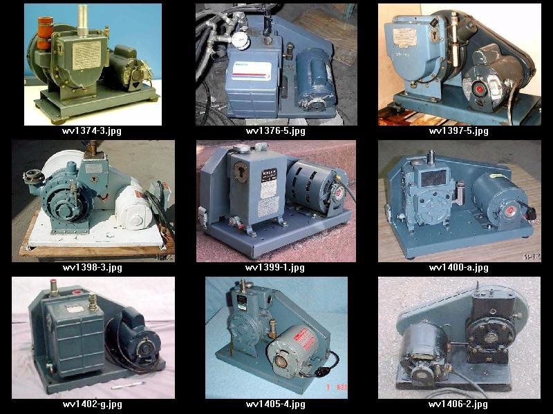
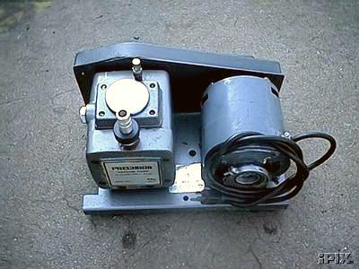
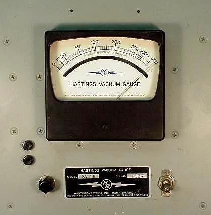
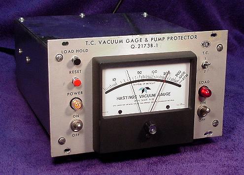
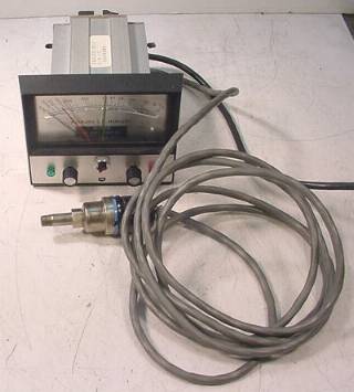
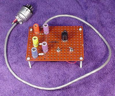
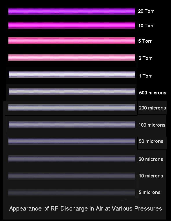