Home Return to Main Page
![]()
Version 7 Installs less amps
and uses helical flashtubes for more uniform pumping and better beam quality.
Version 6 laser gave good power
levels and made average quality holograms. These holograms were much brighter
due to the 1 to 1.5 joule output power. Most of that power was used in object
beam diffused lighting. Version 6's Dual linear flashlamps allowed for compact
electrolytic capacitor power supplies. The beam divergence issue due to dual
linears creating elliptical beams was solved by placing some amps with their
flashlamps in the horizontal position and the other amps in the vertical
position. This averaged the divergence differences to create a circular output
beam. Version 7 begins to address issues of diffraction limited qualities
and spectral qualities of the beam. Larger rods can reduce rod end
fluence densities as beam size could be further expanded. The new ruby
rods are at a .03% cr doping level. It is anticipated, that the lower doping
level and frosted barrel of the rod and use of helical flashlamps will allow a
more even pump concentration in the rod. Amp 1 will use a 1/2" x 7.6"
rod and Amp2 will use a 3/4" x 7.6" rod. The oscillator will use
either a 7mm x115mm rod or a 1/4"x3" rod.
rwmopa7a.gif
Diagram of upgraded version 6.
r7osc.htm
Application notes on the oscillator upgrade.
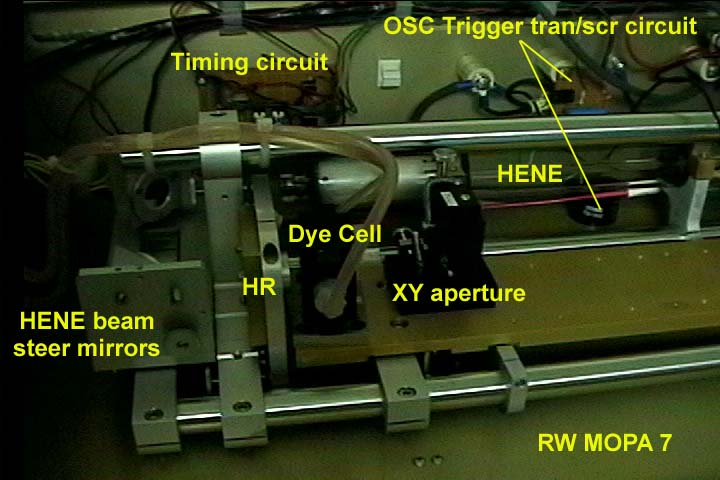
r7h2.jpg
Picture of version 7 during oscillator axial mode study. The resonator frame
also was moved over to make way for the new amps that will be mounted separate
from the resonator frame. Also the dye cell was moved behind the aperture so
that the aperture shielded flashlamp light from hitting dye to improve the dye
cell performance. This way the laser radiation is the light that is used for
operating the dye q switch only.
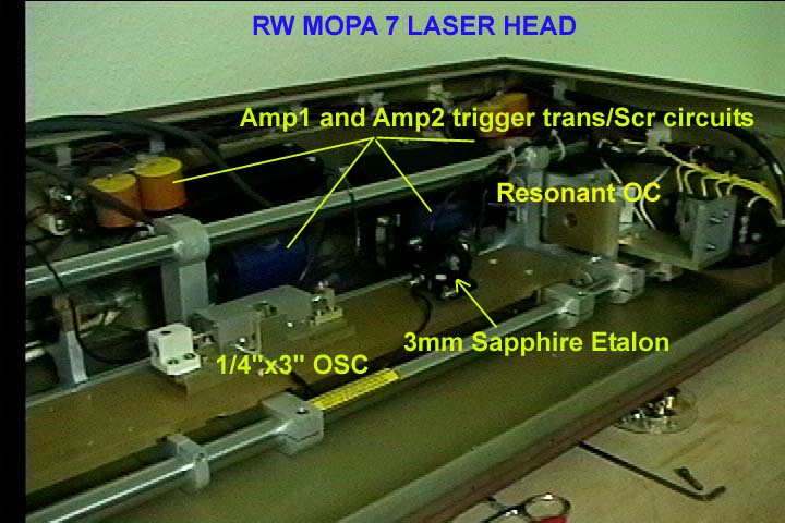
r7h1.jpg
Picture of R7 head looking toward the OC and output beam steering mirrors.
Single longitudinal mode operation has been achieved by aligning the sapphire
etalon with the OC and HR forming additional Fabry Perot resonant distances to
both. The 3mm etalon is 23.5" from the HR and 7" from the OC.
Axial mode study was done with the 1/4"x3" oscillator. The output is
9 to 15 mj at 15 nanosec pulse duration TEM00 mode and single axial mode.
Oscillator was ran at 900volt 520joule input. TEM00 mode assured by using an
aperture set to the Fresnel number 0.6 (1.16mm). Later tests were able to
confirm single mode operation even at single pulse levels of 24 millijoule
output. Power supply was set at 1000volt 660joule input. Aperture was set at
Fresnel number 0.97 (1.51mm). Dye concentration level adjusted to obtain the
single pulse. For best spatial quality the holographic laser will be operated
at Fresnel 0.6 and no more that 15mj output from the oscillator.
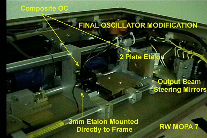
r7h3.jpg
Another Frame member was added and the 3mm etalon/KS1-t mount was mounted
directly to the invar frame to minimize possible thermal variation of the
Composite OC alignment.
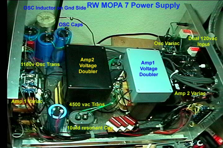
r7p2.jpg
Picture of version 7 power supply which has two power lines, three variacs, and
three transformers: 1 microwave trans for osc, 2 4500vac trans for the amps.
Amps are voltage doubled using doubler caps and rectifiers. The power supply
also contains all low voltage transformers/rectifiers and OSC voltage digital
meter. Front panel contains switches to switch off each power supply at the
variacs and a switch to remove the 300v and 850v trigger voltages as a safety.
Since all voltages can be turned off. The main switch can supply the low
voltages for the HENE pwr supply and the logic circuits so that alignments to
the optics can be made and timing circuits verified when needed. The power
supply uses 2" Ceramic posts are used as terminals to connect HV cables
which will carry upto 7.5kv.
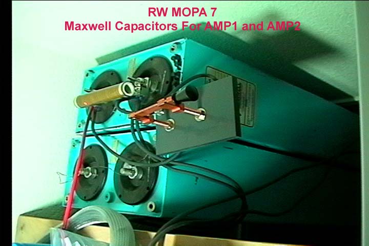
r7p1.jpg Picture
of version 7 amplifier caps to be used. Safety covers, shorting bars, voltage
meters, inductors and additional circuits will be installed over these caps.
Torque by mfg: 15 ft-lbs max.
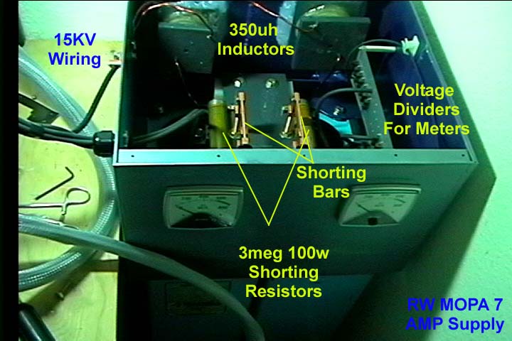
r7p3.jpg Picture
of version 7 amplifier power supply near completion.
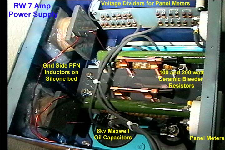
r7p4.jpg Close-up
Picture of completed version 7 amplifier power supply. Inductors are hand wound
10 gauge air coils dipped in resin and fiberglass wrapped. Meter voltage
divider board uses (13) 2watt resistors so that the voltage across each
resistor did not exceed 553 volts. Ceramic Bleeder resistors for storage cap
are the 100 and 200watt rating . Max voltage rating are 4000v each therefore
two resistors are in series
r7sch.gif
Schematic of Power Supply. Just amp circuit is shown. Physically the 5 to
8kv connections from the power supply to the laser head are made point to point
with no plugs. The ends of each 12gauge 15kv cable is terminated with a
soldered ring lug terminal on a ceramic post 2" high. At the laser head
these cables go directly to the pulse transformer connected by ring lug
terminals.
helix.gif
Diagram of helical cavity for amplifier stages. This is the redesign of
2/11/02. Earlier version attempted to enclose the entire lamp and terminals but
had suffered thermal and arcing issues.
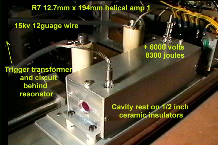
r7amp.jpg External view of helical amplifier cavity using the SG-2600 helical lamp. All aluminum design, small cavity with terminals exterior help eliminate arcing and thermal issues.
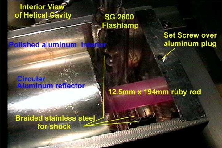
amp1.jpg Internal view of helical amplifier cavity.
r7af.jpg Test firing of osc and Amp. The Amp is producing a high intensity fluorescence light.
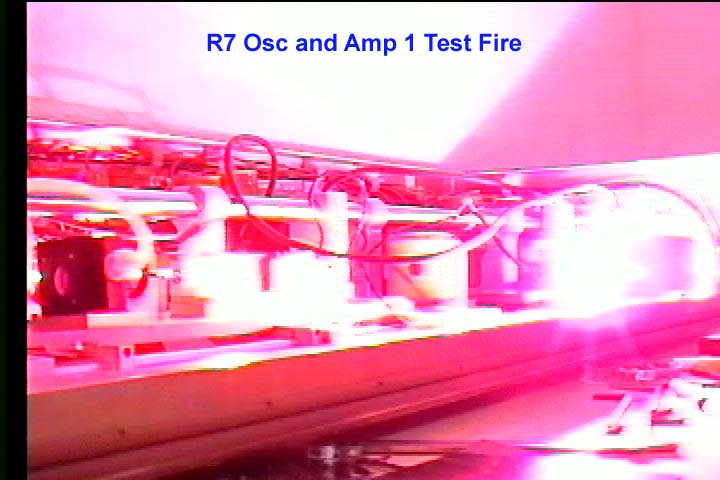
r7af2.jpg Next video frame of test firing. Amp1 increased the 16.1mj osc pulse to 196.5mj. Amp1 electrical input 9400 joules.
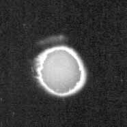
hel128.jpg
128 milljoule output from Amp1 as captured on Kentek Zap-it paper. Notice
a very smooth output across the face of the beam and beam quality from the amp
is more uniform than the dual linear amps of version 6.
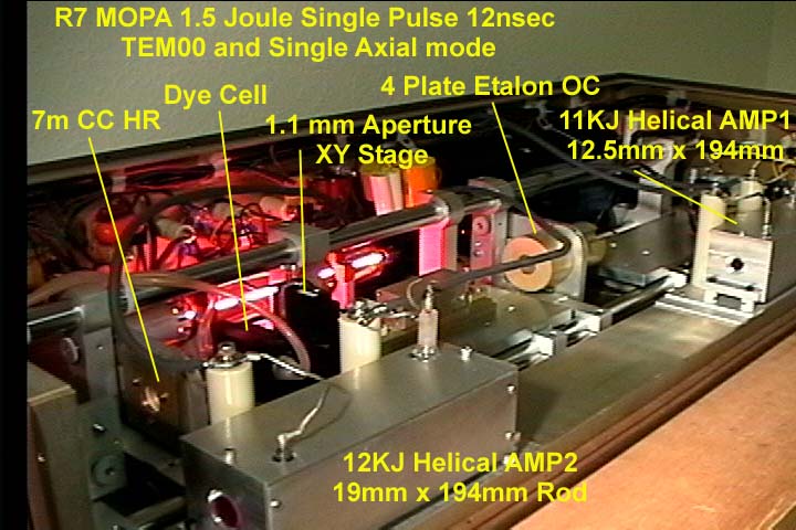
r7mopa.jpg
Tested laser. No preamp used at this time. 24.3kj electrical input
(0.93kj osc, 11.1 kj amp1, 12.2kj amp2) Output was 1.515 joules with 10mj
oscillator. Some thermal surface damage occurred on Amp1 and Amp2 due to
SG-2600 lamps being too close to rod. SG-2800 lamp will be used on AMP2 with a
1.3 inch ID instead of SG-2600 ID of 0.9 inch. Amp1 will be ran with the
SG-2600 lamp but a lower power level of 8 to 9 kjoules to also help
reduce thermal stress for the air cool setup.
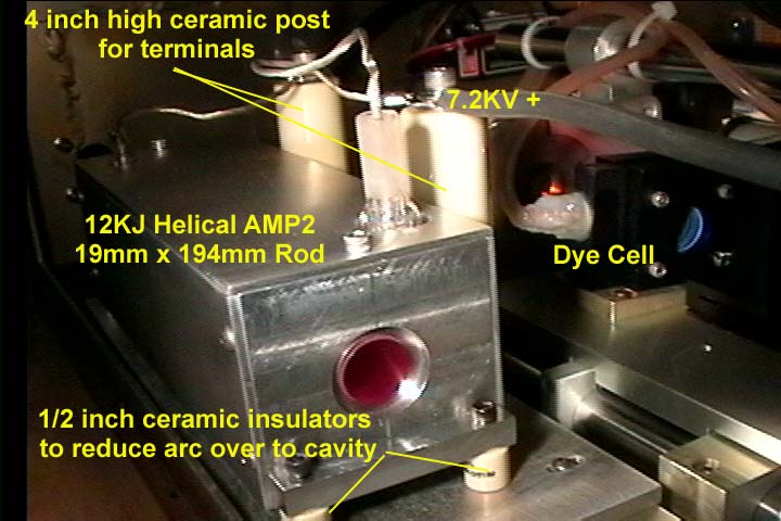
amp2.jpg
view of amplifier 2 using the SG-2600 lamp.
r7resosc.htm
Above new oscillator cavity will now be used as a preamp and old
oscillator was upgraded to a double resonant reflector setup.
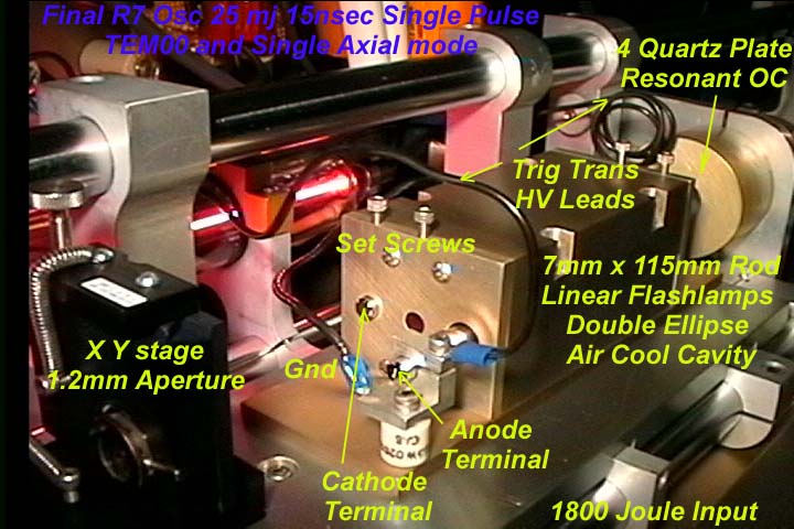
r7fosc.jpg
New oscillator using dual linear flashlamps. Cavity machined as double
ellipse. Each flashlamp is set 0.66 inch from centerline of rod. Eccentricity
0.6 minor axis 0.8 inch. End plates use set screws to hold rod using a aluminum
plug between screw and rod. Also a stainless steel set screw hold cathode
terminal end of flashlamp. Anode terminals exits the cavity onto clamp
holders on ceramic post. Each flashlamp has separate power/trigger
circuit supplying 900 joules each. New cavity setup provided 25 mj 15 nanosec
single pulse and with amplifiers boosting 150x, the final output of the laser
should be 3.7 joules.
r7osc.htm Application notes on the oscillator upgrade to
help reduce axial modes and improve coherence length. Typical number of modes
for version 6 was 2 to 6 modes or a coherence length around 0.5 meter on
average. Version 7 operates in single longitudinal mode and coherence length
increases to 2 to 3 meters instead. Limited by the linewidth of the transform
limited pulsewidth of 12 nanosecs and the additional frequency chirp that ruby
lasers generally undergo.
r7beam.htm Beam profiles of the version 7
oscillator from the application notes on the oscillator upgrade. For
Plano-Concave resonator, use weights.xls below to calculate the passive
resonator geometry including the Fresnel number.
r7resosc.htm
R7 upgraded using double resonant reflectors installed in the oscillator
resonator configuration.
r7mopa.jpg
Assembled version 7 laser head. 24.3KJ electrical input. 1.5
joule TEM00 and single longitudinal mode output. 12 nanosec 10 mj pulse
amplified 150x of helical pumped amplifiers: Amp1: 1/2 inch dia. x 7.6 inch
long rod and Amp2: 3/4 inch dia. x 7.6 inch long rod. Osc ran at 384
electrical joules/cm3 of ruby rod. Amp 1 ran at 453J/cm3 Amp
2 ran at 221J/cm3 . Output from osc was beam expanded by
25mmCC/150mmCX telescope (6x). Beam expander was adjusted to give a moderate
beam divergence as it passed though the amps. Laser produced very smooth and
round 12mm diameter beam at ouput.
r7fosc.htm
New
modification for version 7: Dual flashlamp oscillator.
HELICAL FLASHLAMP INFORMATION
SECTION.
The helical flashlamps are
Spaceglass SG-2600 for both Amps It is recommended not to
run helicals over 40% of their max value and generally should be ran at 20% for
longer life (50,000 flashes instead of 250).
The SG-2600 flashlamp are powered
by a 460 ufd 8kv Maxwell oil capacitor for each amp Inaddition each
circuit contains a LM640 trigger transformer and inductors to get to 400 uh for
a current pulse of 1.2 millisecs. Each amp will be pumped to a 200-380j/cm3
electrical input level. Amp1 is pumped at 9400 joules and amp2 13000
joules Which should make an energy storage of 2.5 to 3.3 j/cm3 for the
amplifiers. At this level a 15mj single pulse from the oscillator should be
amplified to a 2 joule pulse and due to the pulse having been beam expanded by
a telescope the energy density should be around 3 j/cm2 and therefore below the
damage threshold for the rod end and AR coat. The beam size exiting the amp
rods will be around 10 to 12 mm in size. This should yield a 1.4x rod aperture
factor over the beam size allowing for lower diffraction effects. All other
optical components have a tilt to minimize a back reflection from entering a
previous amplifier. In these amp rods the rod itself has had both rod ends
ground and polished parallel with each other and with a 2 degree tilt with
respect to the rod's axis to accomplish the same thing. Construction is under
way and will report actual performance once completed.
Helicals are often filled with
lower torr levels of around 300 to 350 for easy triggering and therefore will
also depending on arc length have a min and max voltage range for the supply.
For example for SG-2600 with an arc length of 113.9cm the min supply voltage is
3k and below this then it will not fire even if the correct trigger voltage is
used. Above 10K for a supply voltage the tube may self trigger. Linears at 16cm
and higher torr of 450 may only have a min of 600v and a max of 3kv. Triggering
long helicals like the 6" to 8" variety generally require 25 to 35kv.
It appears for the SG-26000 and the K6, the LM640 trigger transformer, a 25 to
1 voltage ratio, a 21kv trigger would work. Which means a primary supply of 819
volts upgrading from the 600v I had used before to trigger the 5" long
linear flashlamps. The triggering SCRs will be upgraded to the 1200v 35amp type
(I.R. 40TPS12) and going from the 0.2ufd currently used to 2 ufd for more
current dumping into the primary. Peak current is estimated at 600 amps which
is at the max value for the 40TPS12 SCR (circuit is 3uh primary, 2 ufd cap 0.65
joules).
Another issue is helicals should
be supported in the middle of the coils or have a reflector that will do this.
Inaddition due to shock and thermal issues the coils will expand and the unit
will uncoil slightly during firing so the connections have to take this
movement into account. Companies like Apollo and Korad used a flexible
connection with a braided cable connected at one end to allow this movement.
Since I will fire this only once per 30mins or more then it can be air cooled
instead of water cooled. The main issue is the thermal time for the laser rod
to cool as an air cooled head will absorb more of the long IR wavelengths from the
hot flashlamp. Yet since it air cools by convection at a slower rate the
thermal stress on the crystal is less than a water cooled rod. Ruby has a
thermal shock value of 100w/cm compared to yag's 7.9w/cm and glass 1w/cm (
Walter Koechner. Solid State Laser Engineering).
Technical data on the
helicals: helical.htm
In regard to the K6 lamps:
I would suggest a 1 msec pulse
length instead and limit the joules to 8000 or less limiting to 28% of
explosion or less. I found that to get the unit to flash I had to set the
supply voltage at 4400 volts minimal and the trigger circuit had to use a 2 ufd
cap at 819 volt fired into a LM640 (25 to 1) trigger transformer as an inline
series injection setup which produced a high enough current spark to get the
flashlamp to fire. For this lamp the DI/DT or the rate of current has to be
great enough for the trigger to fire the lamp, even though the trigger voltage
is enough. I fired the lamp at 5200 volts at 468 ufd into 360uh circuit to
yield a 6400j pulse at 1.5 msec pulse width. I think the proper circuit would
be around 200 ufd and 8000v to get the damping factor closer to 0.8.
In regard to the SG-2600 lamps:
It turned out that in this setup,
the main energy supply voltage had to be above 6000volts inorder for the
flashlamps to fire and inaddition, 3ufd on trigger primary was required
to get reliable firings. Most of this is due to the new cavity design for the
flashlamp where the aluminum cavity is isolated from ground by 1/2 inch ceramic
posts. Therefore no grounding planes are brought near the anode to help in
triggering which would allow lower bank voltage and less trigger spark current
inorder to fire. The use of a grounding plane was not used to prevent potential
arc-overs. In the K6 lamp experiments the lamp was held over ground plane which
allowed easlier triggering and lower bank voltage but cavity arc overs had also
occurred when using aluminum enclosures. In the SG-2600 setup, the terminals
are moved to the outside of the cavity to reduce uv ionization and the cavities
are isolated from ground.
amp1cur.gif
Actual performance of SG-2600 with circuit. 458ufd, 360 uh,
6400volts. Based on lamp rise time of 200usec and 3000 amp peak. Damping
factor was near 1.5, Rt is calculated to be 1.28 ohms, Zo = 0.86 ohms.
and Ko is around 112 ohm-amps1/2
Updates:
8/14/02. Well almost
finished, instead decided to upgrade osc to dual lamp design for more power
output by using a longer rod (115mm). This will ease amplifier requirements.
Amp2 lamp broke due to too loose support and it banged into 3/4 ruby rod. This
also caused some surface damage from the hot lamp. Amplifier 2 will be rebuilt
with larger diameter helical lamp SG-2800. Amp 1 will be ran at lower power
levels.
7/28/02 Laser finished!!!
Ready to checkout holographic quality.
7/14/02. Double Resonant
reflectors abandoned for Plano concave arrangement again. 4 Plate etalon used
for OC. 16mj single axial mode output. 1.1mm aperture (0.8 fresnel number) for
TEM00. 19inch resonator length.
6/14/02. Resonator mirror
separation was reduced to 20.5 inch and the 3mm etalon was placed at 17.5 inch.
Since the laser was single axial mode then the coherence length was long enough
even after this change. The change was made to allow a pre amp to be used in
the future if higher energies was needed. The beam expander was increased to a
6x for better fill of the amplifiers. New oscillator cavity with 7mm x 115mm
rod was removed for use as future pre amp and 1/4"x3" modified tank
cavity was reinstalled as the oscillator.
6/03/02 at 8300 joules the helical
lamp melted the glass wool used to shock absorb the lamp. Instead heavy duty
aluminum foil was used. This also melted so braided stainless steel mesh used
instead. This was obtained from braided water supply lines. Will make amp 2
larger than 2.3inch x 2.3 inch x 7.8 inch. Instead 2.3"x2.6"x
7.9 inch. 2.6" will allow more room for the helical glass terminals so
lamp is symetrically centered over rod. 8" long will increase cavity
inside length from 7.1" to 7.2" to minimize rod shielding by holders.
5/29/02 A smaller rectangular
cavity was designed: 2.3"x2.3"x7.8" to contain the custom
designed spaceglass SG-2600 Flashlamp (helical flashlamp with flexible leads). This
cavity was mounted on 1/2 inch ceramic posts to isolate the cavity from ground.
The flashlamp anode and cathode ends extended from two holes on top the
all aluminum cavity. 4" ceramic post are positioned beside the cavity for
attaching the power supply cables and the flashlamp flexible leads. Flashlamp
has a metallic reflector 1/16" sheet wrapped around the flashlamp. The
flashlamp was installed in the cavity with refractory wool on outer edge of
each flashlamp terminal to reduce the lamp shock within the cavity.The
flashlamp fired at 5800 volts. 458ufd capacitor yielded 7800 joules during
first test run without ruby rod installed.
1/16/02 - Used Teflon, PVC with
overlapping dove tail joints to provide electrical isolation of the anode
terminal. This allowed the cavity to be used but the plastics still suffered
from heat and electrical stress. So will be abandoned as insulation material
for the cavity. Instead will look toward ceramic sheets.
1/2/02 - Update: Tested the new
helical cavity. Lamp and rod in large aluminum enclosure and immediately had
flashover to cavity box ground. This HV short to ground also caused a voltage
reversal and blew the charging diodes. This reversal was caused by having the
inductors in the flashlamp path and not directly in the capacitor charging
path. So the caps will be wired where they get charged and discharged with the
cap and inductor in series. This will prevent a voltage reversal setup by
oscillatory currents due to too low inductance vs resistance in the circuit if a
flashover ever occurs again. The flashover was not caused by the 25kv trigger
pulse as originally thought to have happened but by the flashlamp firing and
additionally creating a UV ionized path to ground for the lamp anode. So
currently seeking to find better insulation for the anode that can take UV and
increase the path length even more as to prevent arc overs from occurring. Also
better methods of securing the flashlamp and removing any strain on the
terminals so the flashlamp can fire, expand (and slight uncoiling) and absorb
the shock without putting too much stress on the lamp terminals where cracking
and lamp failure has been occurring. This method needs to be able to also offer
springiness for shock, high heat capability and uv resistance.
![]()