Home Return to Main Page
RW MOPA Version 6 Application
Notes. Updated 7/18/01 (Below)
rwmopa6.gif Diagram of Version 6
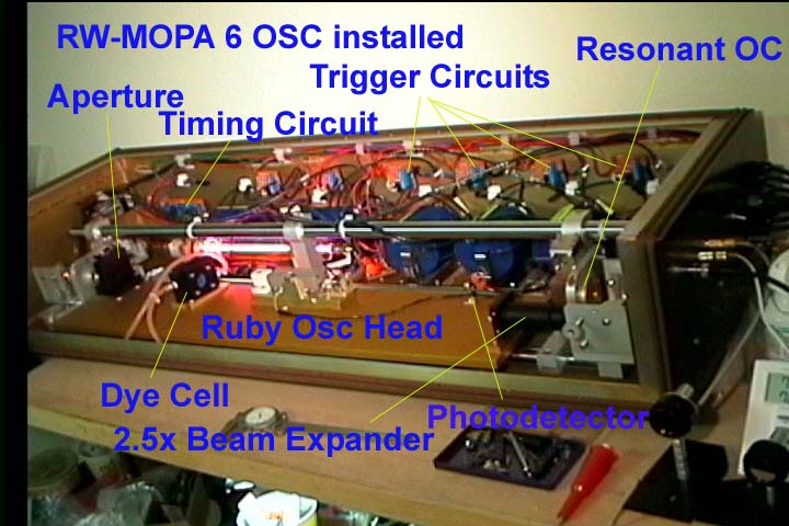
rwmopa6.jpg First Photo of Version 6
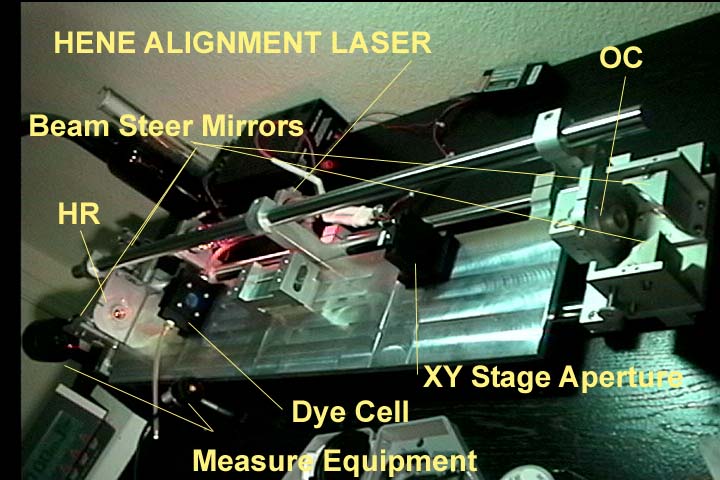
r6osc.jpgPhoto of Oscillator Installed
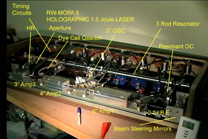
ruby.jpg Version 6 at 1.5 to 2 joules. 13" of
power amps
ruby.jpg 3/8" diameter
amps. Version 6.
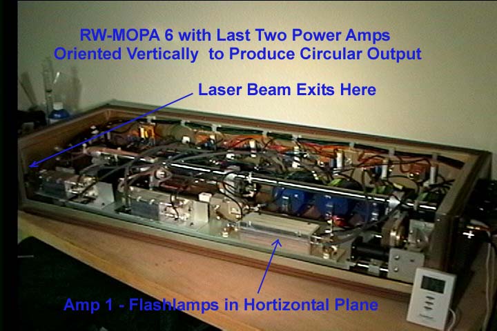
rw6vo.jpg Final Photo of Version 6 corrected for
elliptical beam and l2" of power amps (1 to 1.5 joules).
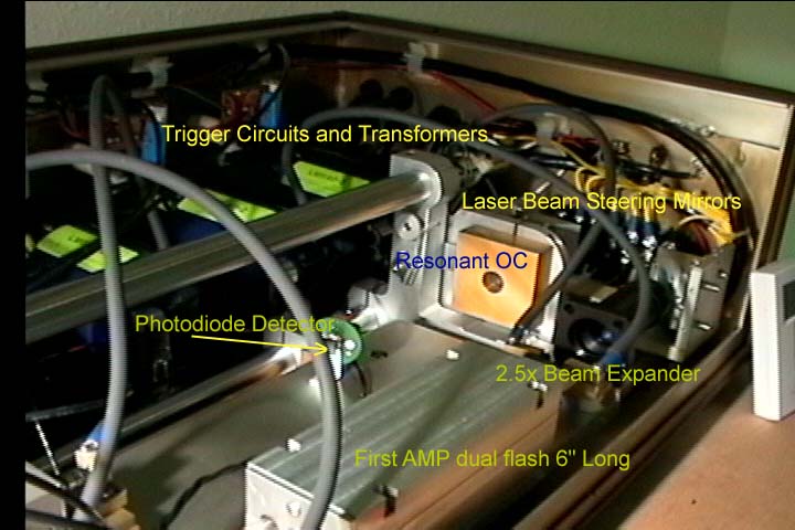
oc.jpg OC End of Laser Head.
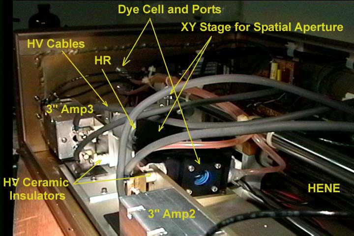
hr.jpg HR End of Laser Head.
cavray.htm Ray trace of dual flashlamp cavity.
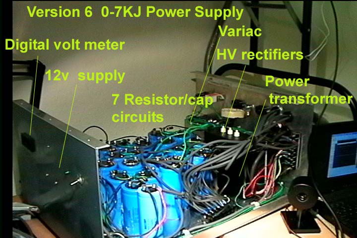
pw65.jpg Old Picture of ver 6
power supply. The new one (modified) is 8kjoules
Lessions learned have pointed the
way for this version: more stable resonator with higher resolution optic
mounts, Higher gain by using a beam expander and larger diameter ruby rod
amplifiers, tilting all optical axis to reduce backreflections, dual pump the
amps to get more uniform pump distributions. The 3/8" ruby rods that I will
be using for amplifiers were from various auction sales and suppliers and have
frosted sides to help diffuse the input pump light
A 3 rod (3/4 inch diameter Invar x
36" long) resonator mount is used with a coaxial 6 mw HENE installed.
Although for the purpose of a pulse laser like ruby, stainless steel rods would
work okay as Invar is very expensive. The laser's basic design is like
RW-MOPA-5 but the HR/dye cell is replaced with a standard HR and a newly
designed two window dye cell. These 694 nm vcoat single side AR windows were
purchased from CVI laser. This feature allows me to change HR out as future
testing allows. The oscillator is a 1/4"x3" rod in a single flashlamp
arrangement. Amp1 is a dual pumped 3/8" by 6" ruby rod, Amp2 is a 3/8"
x 4" rod and the Amp3 is 3/8" by 3" rod. The amps were arranged
like this to yield max aperture when having to tilt the rods to avoid back
reflections intercepting the previous stages. The shorter rods can be tilted
more than the longer ones so when the beam is at it's minsize the longer rods
are used first. Extra care is being taken to eliminate non uniform pumping to
achieve even a higher quality TEM00 mode beam by the use of dual cavities. But
what was found out was that the beam shape did become elliptical due to larger divergence
in the plane of where the lamps are. The output beam became 6.8mm wide by 4.5mm
high due to this difference in divergence. This also required that the tilting
of the rods in the vertical direction to maximize the available aperture to
beam size to reduce diffraction effects caused by limited aperture size of the
tilted rods. Diffraction was calculated to be no more than 4% peak to peak per
AMP2 and AMP3. Diffraction was very low for amp 1 since it had the smallest
beam size and the least tilt (and reduced aperture due to tilt). The use of
ruby AR prisms in RW-MOPA-5 have been replaced with ruby-dielectric coat front
surface flat mirrors 1"x 0.25" set to 45 degree incidence to help
eliminate extra surface reflections. The main problem with RW-MOPA 5 which used
the 1/4x3" rods (1 for the oscillator and 4 for the amplifier) was the
power density grew upwards of 11 to 19 joules/cm2 which contributed to AR
coating burns or pitting problems of the ruby rod ends. Inaddition the maximum
gain was around 180 to 360 millijoules depending on the number of pulses. But
RW-MOPA-3 to RW-MOPA-5 showed the potential for these surplus items.
Calculations show you could use a beam expander of around 1.5x magnification on
my earlier versions and this would reduce the high power density problem. These
calcs reveal that RW-MOPA-5 would have produced 500mjoules and kept the power
density down to 8joules/cm2. Therefore the use of a BEAM EXPANDER IS A MUST FOR
THE LASER DESIGNER. Technically you would want to keep the beam diameter at 1/2
the radius of the rod for the lowest diffraction effect. Later I would find by
using larger rods and lowering the beam density that much greater gains could
be achieved per rod length (due to more rod volume) and RW-MOPA-6 is designed
to yield 1.0 to 1.5 joules at a power density of 7j/cm2 which will protect the
rod and optics. Larger rods demand more power so the power supply increased
from 5kj to 8kj).
Experiments with using two 3"
rods in series in the resonator (master oscillator) proved that this idea gave
more gain but even at 0.8mm aperture I couldn't kill the other spatial modes
and dropped that idea for the new laser. Currently the new resonator has the
following specs: 1"x0.375" 7meter concave HR, a resonant reflector. A
resonator length of 77cm, G of .889, an exit beam waist of 1.39 mm, 6% mode
size increase at HR with a 1.4mm aperture for tem00 mode yielding a Fresnel
number 0.91 and a loss of 16.5% for TEM00 mode and 45% loss for the TEM01 mode
per pass. I changed from a 3 meter HR used in RW-MOPA 5 to gain more mode
volume through the ruby rod for higher output since I now use 4" gimbals
mounts for alignments. RW-MOPA-5 used 1.5" mounts for fine tuning the
resonator. A 3m HR gave a lower G value for a wider tolerance of mirror misalignment,
but at a sacrifice to mode volume size of the active region in the rod and the
corresponding lower power output of the oscillator. In addition, a higher
tolerance of alignment also requires a more stable structure to hold those
mirrors.
I tried using some solid saturable
absorbers set at brewster angle. Test proved that I would have to limit the
output of the oscillator to 8mj in order to get good q switch modes with the
solid type as it was not adjustable. I decided that the DOTCI/ethanol for it
drawbacks on maintenance issue was still superior for pulse control on setups
of 2, 3, or 4 pulses. Also the liquid dye method allowed adjustments to give
outputs of up to 32 millijoules. Overall I found the Q switch mode can be 1/2
of the free running mode of either saturable absorber. You adjust the solid one
by input power or aperture setting. The liquid type is adjusted by setting
desired input power and aperture and then adjusting dye concentration to get
desired q switch behavior. As you increase the dye the laser goes from free
running to multiple pulses, to single pulse and finally to no pulse. The new
flow through cell design allows me to take apart the cell and clean or replace
items when necessary over the HR cell design. Also I plan on giving the new
cell a slight tilt even with AR coats to eliminate resonance or reflections in
the systems.
For the best quality for your
holographic laser, always use optics in the resonator portion of at least
lambda 1/10 and surface quality of 10/5. As hundreds and some thousand passes
may be done through these. There is always more tolerance later downstream as
wavefront errors are accumulative overall in the entire holographic setup.
3/18/01 - Machined a mount for the resonant Output
Coupler. Installed a 7meter concave HR from CVI laser. 1"x 0.375"
optic, too bad I found out too late that it also reflected too much of the HENE
laser as I got poor transmission through it (I should have specified AR for
632.8nm P/n SWP-0-R694-T632-SMCC-1037-7.00CC $596 ouch! vs $225 for the regular
one P/n R1-1037-0-7.00CC) Installed XY translation stage with Aperture. Found
out that the aperture mounted on the OC side gave beautifully round and clean
TEM01 and TEM10 modes! Couldn't kill either even down to 1mm aperture. At 1.5mm
multimode began. When I switched the stage and aperture to the HR side, I got
TEM00 mode even at 1.4 mm. Installed Dye cell and Photodetector and got 54mj
output with a 1.4mm aperture and free running. When DOTCI dye was added, I got
a 19mj single pulse with 35nanoseconds of pulse width. Dye concentration was
measured at 11.8% loss per pass. By the way the oscillator output was measured
after the beam expander and this was found to only reduce output by less than
8%. The beam expander was made from Thorlabs parts: SM1 lens tubes, holders and
two AR coated lens. I think the -B AR coat lens from Thorlabs may have a low
energy limit. The expander increased the beam size by 2.5X (a 30mm plano
concave and a 75mm plano convex). This decreases the 1.4 joule/cm2 power
density down to 0.23 j/cm2 for the entrance into the amp stages with a beam
size of 3.9mm.
Flashlamp pulse was 750 usecs due
to 1160ufd and 58uh circuit at 1110volts. Approximate 700 joule input to
oscillator. Updated the RW-MOPA 5 power supply by adding two more circuits from
5 to now 7 flashlamp circuits. (1 for osc, 2 for amp1, 2 for amp2 and 2 for
amp3). Changed cable design from quick disconnect to direct lug to lug
attachment to minimize possible arc overs that had occurred on some plugs. Also
beefed up the 12volt supply circuit to drive the HENE in the laser head and
also to supply regulated power for the photodetector and timing circuit also in
the head. The laser head contains the timing circuit, trigger circuits, and
trigger transformers. Oscillator uses an EG&G 35uh series trigger trans
with a 23uh air coil. Amps will use Laser module's LM640-2 trigger trans at
56uh for each flashtube. Trigger circuit is SCR triggered (ECG 5450 - 25amp
800v) with 300volt supply.
3/18/01 - Tested LM640-2 trigger trans and they
needed 600v to at 200nfd to fire the flashtubes. Updated Power supply and
provide 600volts in addition to the 300v needed for the osc trigger trans.
6/16/01 - Performance of the dual cavity looked
dismal as only 1.35x energy boost to the oscillator signal. I was concerned
that the cavity might not be as efficient as an elliptical. Traced problem to
the timing electronics. Problem was the oscillator was firing at the same time
the amp was. Normally you want the amp to fire first and store the flashlamp
pump before the oscillator fires. The problem was corrected by using a shielded
coax for the osc trigger wire and by addition of optoisolators, separate ground
for NE556 timers and separate 12volt supply with some wiring run changes to
minimize pickup of trigger pulse from the trigger circuits.
With the ability to adjust the
delay again it was found that I could obtain 4.3x amplification in a 3"
amp! The delay was set to 426 usec. The flashlamp pulse width is 1msec for
oscillators and amps. Oscillator pulse arrives 300 usecs later from its
flashlamp pulse . Therefore the total delay for the amp is 726 microsecs. These
timing circuit fixes have proved critical to the laser's performance! RW-MOPA 6
would put out 1100 mjoules properly timed but if the oscillator fired when the
amps did the same laser would only put out 330 to 450 mjoules! The final
overall system performance showed a signal boost of 100x or around 3.7
joule/cm3 pumping. As a final note a ray trace of the cavity showed generally good
performance. The cavity dimensions are 1.45 inch wide and 5/8" wide. The
flashlamps and ruby rod are 3/8" inch. The flashlamps are placed at their
widest and next to the reflector. The cavity was milled flat in the center and
had a 5/16" radii on each end next to the flashlamps as this provides a
bit larger reflector to allow the flashlamp to achieve a greater than 180
degree radiation pattern without being absorbed by the flashlamp blackbody.
Also updated the power supply.
Added another variac and microwave transformer for the 6" amp(7/16/01).
2025v and 1600 joules per lamp from 5 resistor divided 3900ufd caps (total is
780ufd) and 110uh trigger trans and inductor yield a pulse of 900 microseconds.
The inductor was an additional 54uh air coil to properly adjust the circuit to
110uh. At 1189 volts for osc, amp2, and amp3 the supply provides 819, 1837 and
1837 joules. Amp 1 at 2025 volts receives 3200 joules.
7/17/01 to 8/28/01- Installed plano concave lens in a SM1 tube
and mount for the external output port. Tilted rods vertically, due to
elliptical TEM00 mode output of 6.8mm by 4.5mm. Each amp further causes more
divergence in the horizontal plane due to thermal lensing from the absorption
of the pump energy. In order to correct this problem the last two amps have to
be reoriented vertically to increase the divergence in the vertical direction.
Output of the laser is from 1 joules to over 2 joules depending on the number
of pulses (1 to 5 pulses).