Home Return to Main Page
HOLOGRAPHIC YAG LASER Version 1
![]()
CONSTRUCTION
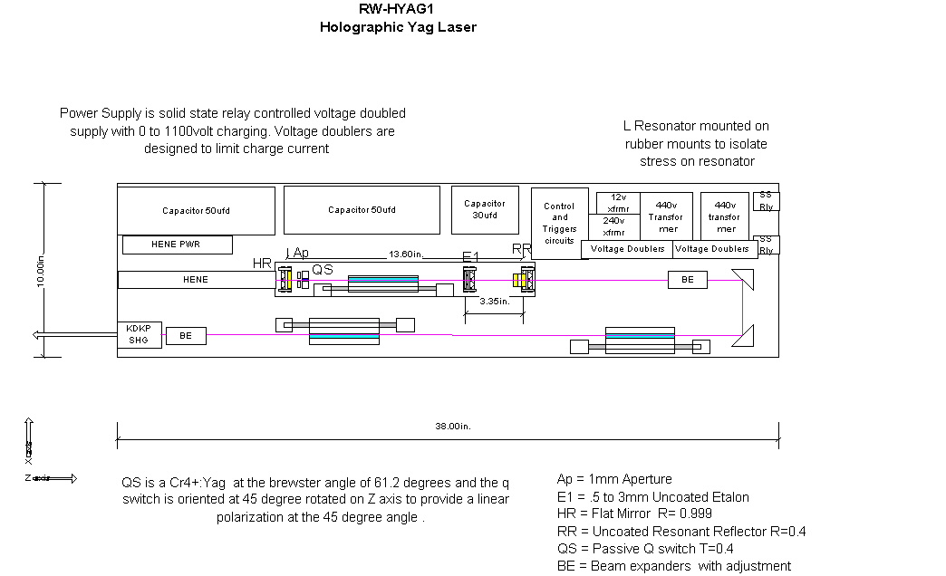
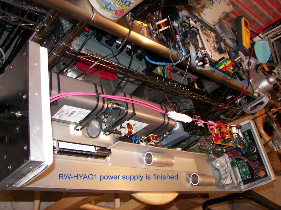
First laser design to test: rwhyag1.jpg The system is air/conduction cooled, integrated power and laser in one package, runs on 120vac 60HZ @ less than 3amps, and uses three L8493E 7mm x 100mm flashlamps for the three 6.35x100mm yag rods. These rods make good amplifiers, but to keep it simple it was also used in the oscillator. Therefore due to these rods' specific volume of Nd:yag material and cavity reflector material, a larger supply of pump energy was required and detailed below.
Chassis was built on a 10 inch x 38 inch 1/2 thick T6061 Aluminum plate. Basically the breadboard approach to setup of components using tapped holes but offering only small amount of stiffness unlike a true optical breadboard design. The actual resonator therefore will have additional isolation mounts. 1" aluminum angle brackets were attached to the sides and also used to construct the ends. 1/16" aluminum sheet was used to cover the ends. An 1/8" aluminum top cover was made also. Side brackets and end brackets were drilled to allow top cover to held by screws. Base plate was drilled and tapped for all electrical components or their attachment points and for attaching side rails and the end pieces. 6-32 screws were used to attach all these chassis parts. Optical parts where attached with 8-32 screws to the base.
POWER SUPPLY
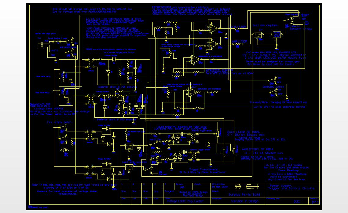
yag2.dxf Schematic of rwhyag2 design. This is a voltage doubler setup for 60usec pulse circuits for 3 lamps using two external trigger circuits. The pulse width was determined by the available capacitor/space issues. Both amps will share the HV trigger.
yagsch2.jpg JPEG of the schematic but better to use dxf viewer as you can zoom/pan etc for better detail.
Free dxf viewer from Solid works: http://www.solidworks.com/pages/products/DWGgateway/eDrawings-Free3Dand2DCADViewerandPublisher.html
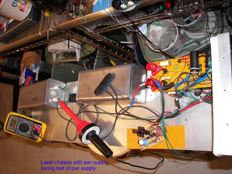
yagpwr1.jpg yagpwr2.jpg yagpwr3.jpg yagpwr4.jpg Testing of power supply
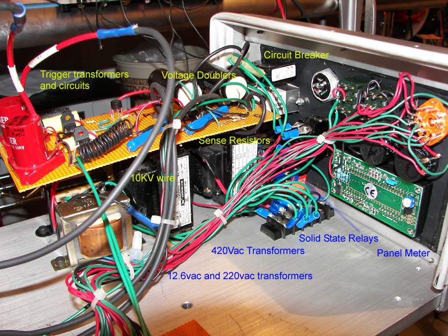
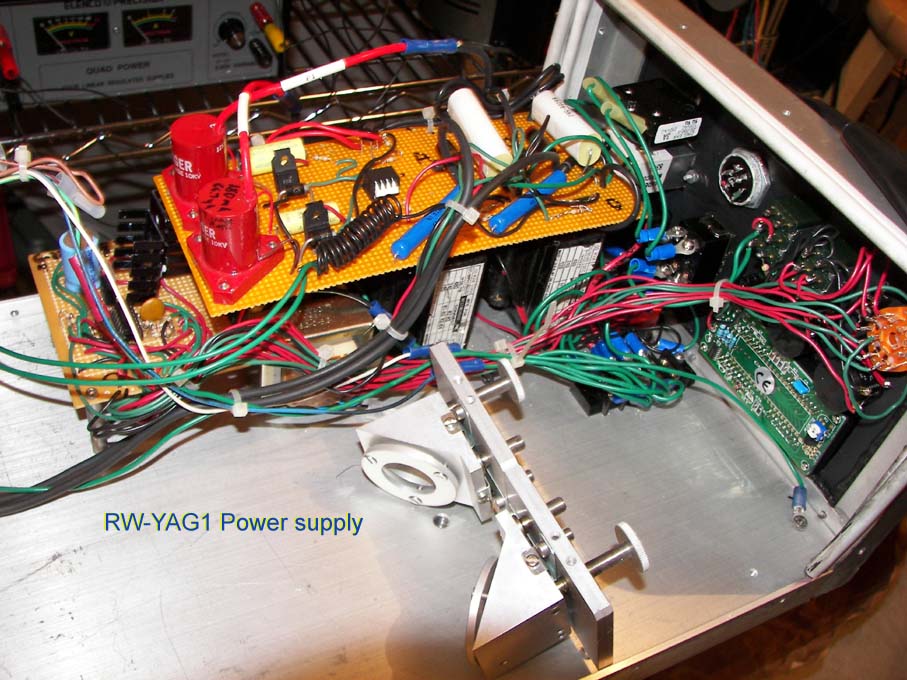
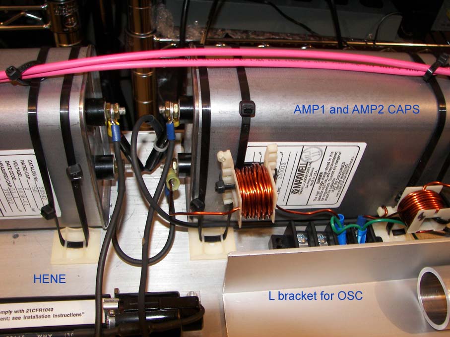
ryagpwr1.jpg ryagpwr2.jpg ryagpwr3.jpg Closeups of finished power supply.
rhyag1.jpg Power supply is complete for first version of Holographic yag laser.
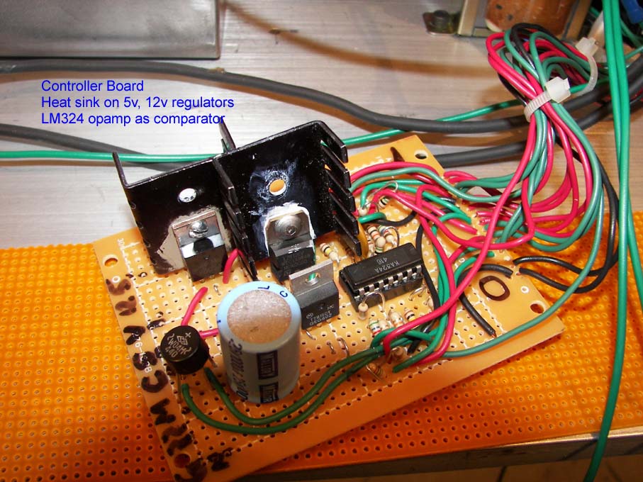
The above circuit design allows for a compact power supply. Simpler designs use variacs for voltage control but are bulky. Two solid state relays and a one LM324 opamp control the charging on time of the system. Of course variacs are linear devices so this relaxes the requirement on the charging transformer since the variac can compensate for the desired output voltage. But on a solid state relay system, the full voltage is applied for the duration of the on period, therefore the charging transformer peak voltage can not exceed the voltage ratings for the energy capacitors. For example, the power transformer can not exceed 440vac RMS if a 1200vdc storage capacitor is used. 440vac x 1.414 = 622.16 * 2 (voltage doubled) = 1244.32volts minus the rectifier diode voltage drop. Another safety issue is that there exists an electrical shock hazard using SSRs because they leak current and therefore energize the transformer. Losses in the transformer and bleeder resistors (the sampling resistors) in this design reduce the ability of the storage capacitor to charge when the charge switch in off. But the voltage is present and the only way to remove it is to make sure the power switch is OFF. On the main capacitors 30volts was found due to SSR leakage.
As designed above the use of a half wave voltage doubler uses a small capacitor to charge the main capacitor and based on it's size will limit the charge current rate. Ideally with no load the max voltage would be 2x the peak as detailed above for the given transformer. But the sampling resistors and safety bleeder resistors add a current load to the voltage doubler. The voltage drop is roughly equal to the current load divided by the capacitance times the line frequency. 927ua/(60hz*.22ufd) equals around 70 volt drop so the main capacitor should charge to 1100 to 1150 volts maximum. A calculation of 1/(2pi()*f*c) gives a impedance of 12k for the 0.22ufd cap and the ( avg current 880vac RMS/12k ) * 880vac = 65VA or larger transformer should be used. In this case a 50VA transformer was used since the firing duty cycle was low. Less voltage drop requires a higher rated VA transformer to allow for a larger current limit capacitor. With the use of 440vac transformers, 1100 volts charging was demonstrated with the voltage doubling circuit.
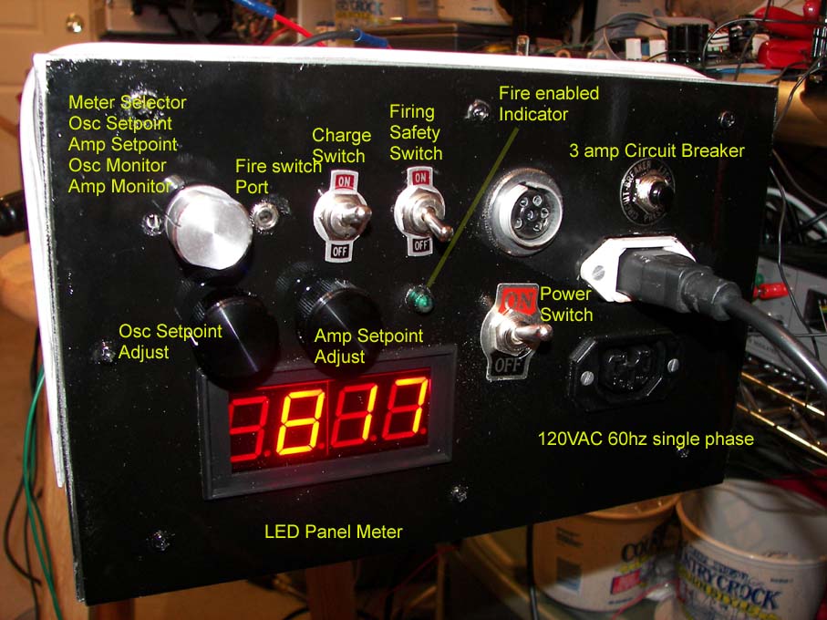
Operation: A Charge switch SW6 is provided that will prevent the laser from charging. The charge off position closes the switch which this shorts the opamp output to ground level preventing them from activation of the solid state relays. The open position is "Charge On" which allows the opamps to operate the SSR. A selector switch SW5 allows the operator to set the panel voltmeter to the voltage references for the Comparators. The potentiometers of R17 and R18 the voltage references to the opamps can be set and verified with the panel voltmeter at the desired maximum charge voltage for the main storage capacitors. Selector switch SW5 can then be set to monitor the indicated voltage on the main storage capacitors. When the Charge switch SW6 is opened and since the comparators sense the low voltage from the main storage caps, they turn on the solid state relays which are located in series with the transformer primary to allow the power transformer to begin charging. The voltmeter via selector switch SW5 can be used to verify that the charge is at the desired setpoint. By the sampling resistors of the charge voltage, the comparators will turn off the power transformers by turning off the solid state relays. Each power supply is independently controlled by it's own comparator and solid state relay.
The sampling voltage divider string made of a high voltage HVX 2M resistor and 1/2 watt 21K-ohm resistors must be accurately measured and resistors selected to allow the correct sampling voltage to the opamp, which will insure the correct cutoff at the desired setpoint. If the setpoint is 9 volts on the reference to opamp Vin+ which can be view with the system's panel voltmeter as 900, then the actual sampling voltage should show 9.3v to the opamp Vin- input and the opamp will cutoff the solid state relay at this point. The actual voltage on the capacitors should be 890 volts. Main storage caps voltage varies from 854 to 890 volts for a setpoint of 900 volts (9v control). Of course actual checking of the charged main capacitors should only be done with a proper 40KV high voltage probe on a voltmeter as demonstrated here: yagpwr2.jpg Since the sampling resistor divider can fail in an open state without draining off the charge, the additional HV bleeder resistors are needed to help assure discharge but it should be assumed that the capacitors are charged and safety precautions taken.
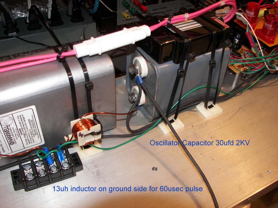
Instead of series injection triggers which have their saturated inductance in the main discharge circuit to deal with, the requirement of short 50 to 100 microsec pump pulse required the use of external trigger circuits. With low inductance oil capacitors and hand wound air core inductor coils it was shown that the use of external triggers allowed for well-developed critically damped 50usec-pulse duration for the flashlamp.
The flashlamps will fire if the FIRE switch is momentarily closed as this provides voltage to the gate of the SCRs D1 and D2 which will short the charged capacitor C1 and C6 into the trigger transformers. These capacitors are charged to 200 volts based on a 2meg bleeder resistor for a 220vac transformer. A safety switch is provided to allow/disallow this transformer from charging C1 and C6. Additionally the 12v FIRE signal above can be removed by a dip switch which allows either or both triggering to occur. This provides a maintenance mode so that only the oscillator is fired during alignments etc.
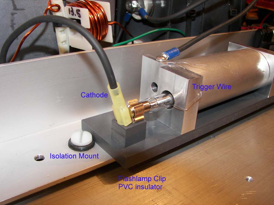
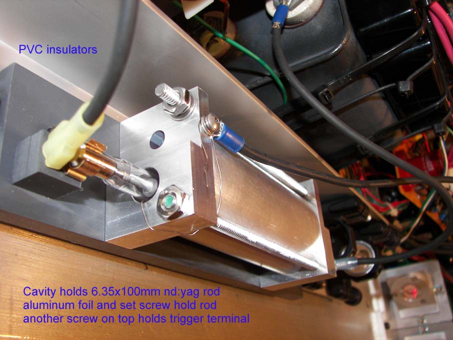
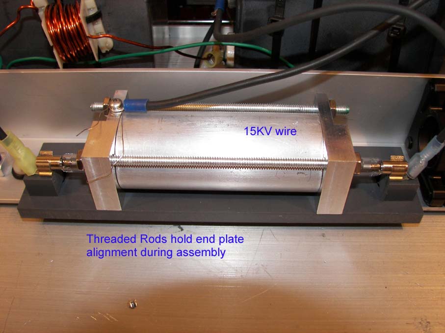
The trigger transformers are 50 to 1 turn ratio, so the secondary will provide 10KV to the lamp cavity and flashtube. The L8493E flashlamps have a trigger wire already wrapped on them and all was needed was to use this wire. Since the lamps are in close proximity to the aluminum cavity, it was decided to insulate the cavity from the system by using a PVC base under the cavity. The flashlamp external trigger wire and cavity connected to the trigger secondary coil. The flashlamp anode and cathode are also insulated by PVC standoffs on t he PVC base. The anode is carrying the energy and current from the main storage capacitors. the cavity only becomes charged by the trigger transformer during firings. The insulated cathode connection of the flashlamp served as the grounding terminal for the trigger and main discharge through the PFN inductor leading to the electrical ground connection. Reliable triggering was found to happen and the cavity insulation was developed to withstand 12k maximum trigger pulse. Additionally since the trigger energizes the cavity temporary at the beginning of the flashlamp discharge, a possibility exist that the main caps could arc over to the cavity but this is prevented by cavity insulation. Since these metal parts become charged during the firing, they are insulated from the laser case as well and personnel should stay away from them since they do become charged with high voltage during that time. Additionally insulators should be over the flashlamp anode terminal to prevent personnel from accidental contact with the main storage capacitors.
Tests showed that when the PFN damping factor went below 0.75 the electrical pulse began to show slight reverse polarity after the pulse. When the power was increased even more, the damping factor dropped and sizable overshoot oscillation began after the pulse at 0.7 damping factor and below. It is important to have both the oscillator and amplifiers using the same pulse width or a timing circuit would be needed to time the oscillator to the amplifier. The capacitors used were low inductance and low resistance and designed for energy discharge. An alternate could be SCR commutation type that allows for a high dV/dT value. Some have values of 10,000+.
The capacitor value along with the inductor determines the pulse width and shape base on the impedance of the flashlamp. Since this was designed for the L8493E lamp which is a 7mm bore by 4 inch long arc length this gave the following circuit values for a 60 usec pulse which was chosen based on available energy storage capacitors that fit the space available. To get a ideal 0.8 damping factor which provides maximum current pulse with no long decay or oscillation ringing, the values of 53ufd and 7.5uH and 1436volts are required for maximum 55j output. Greater than .8 and the rise time of the pulse shortens and the decay of the pulse lengthens. Below 0.7 damping factor and the circuit begins to a dampened oscillation (current ringing). Other calculations can be done via this spreadsheet. weights.xls
The recommended panel meter is a voltmeter made by C&C model PM-1029B which is a 5volt common ground LED panel meter. http://www.web-tronics.com/jumleddigpan.html Quite bright for LED but the PM-1028B model is LCD. In order to set it up properly you have to un-solder(un-short) the pad marked 200mv and solder over the pad marked 20volt. Additionally you do not need to solder any of the decimal points marked P1, P2, or P3. At 10v input the display will read 1000. The panel voltmeter can be adjusted to agree with the actual voltage by setting a small pot on the back of the panel meter.
Specifications of a pulse capacitor. http://www.maxwellcapacitors.com/series-dp-capacitors.html.
For example the laser uses Maxwell part number 30542 which has the specifications:
|
Part |
Cap |
Voltage |
|
Max |
Design |
Approx. |
|
30542 |
50 |
2 |
25 |
25 |
5 x 10⁷ |
100 |
For a 50usec pulse time, the peak amps would be 1271 amps for 30joules. Even at full capacity of 100 joules in 50usec the peak would be 2321 amps. Well below the max peak current. Also since 30 joules only requires 1095volts, this is well below the 2kv rating the design life would not be shortened. The 0.1uh series inductance is low with regard to the required inductance of 22uh for the PFN so is not much of a factor for the inductor selection process.
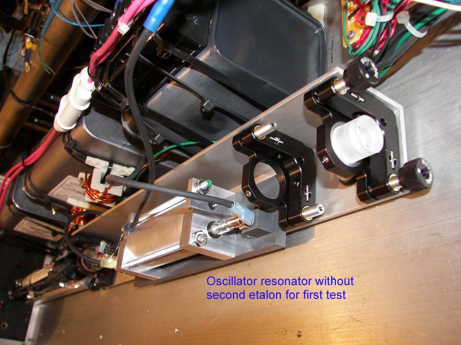
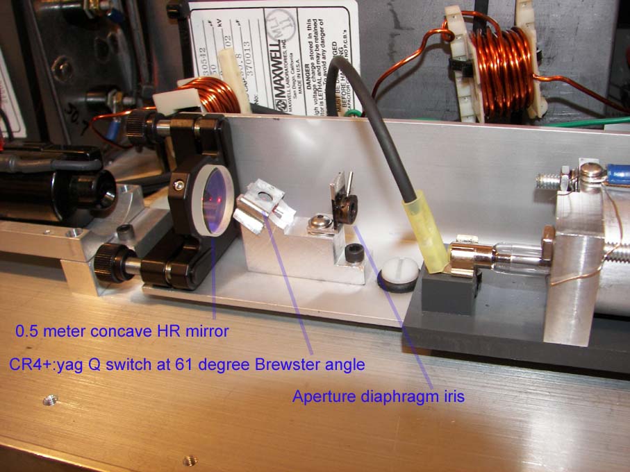
OSCILLATOR PERFORMANCE.
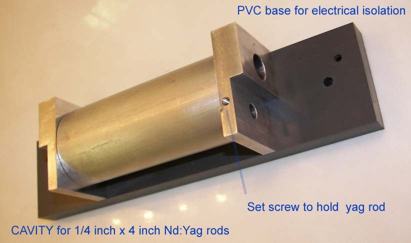
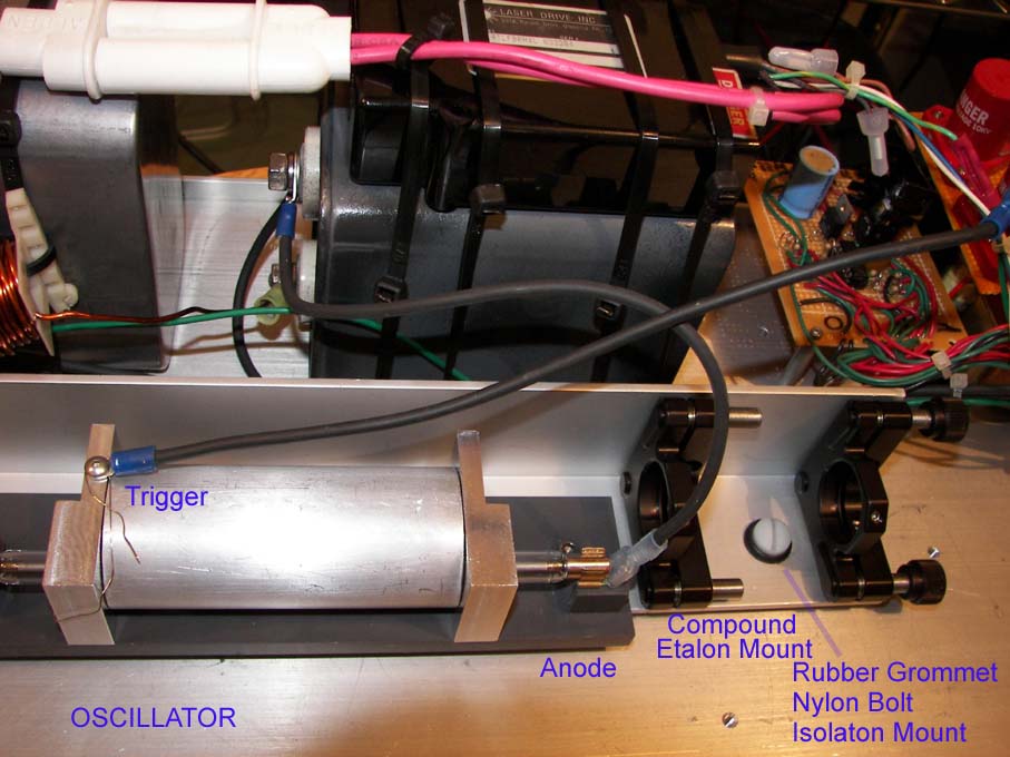
The resonator consist of an 1/8 inch thick 2 inch wide aluminum angle L bracket 15 inches long. Mounted is three Thorlabs KM100 kinematic mounts for the HR, OC, and OC. The resonator is the plano/plano/plano configuration. Isolation mounts to prevent the chassis from mechanical distorting the resonator will mount the resonator to the chassis. This is a rubber grommet with a nylon ¼ inch bolt to secure to chassis. Additionally this mount arrangement was setup to provide electrical isolation of the cavity from the chassis since the cavity becomes charged with 10kv from the external trigger. The anode and cathodes of the flashlamp are also insulated mounted.
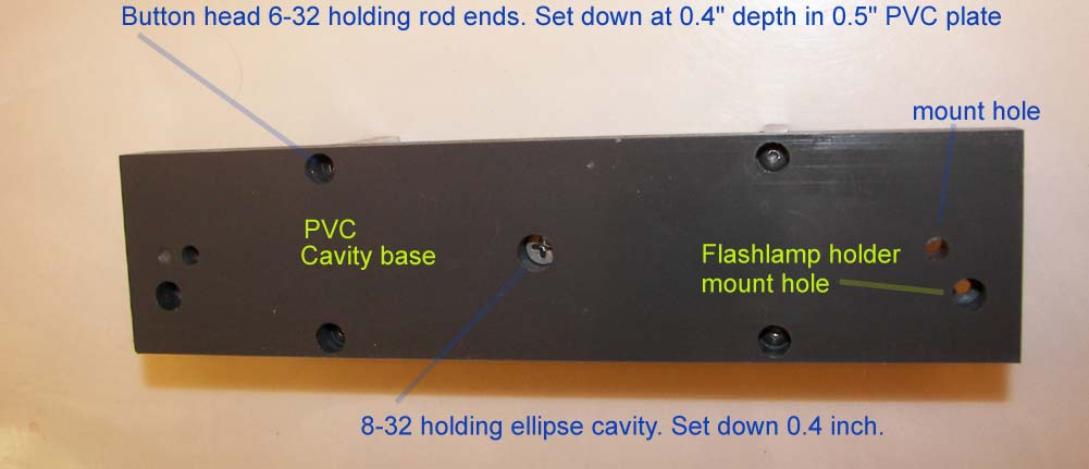
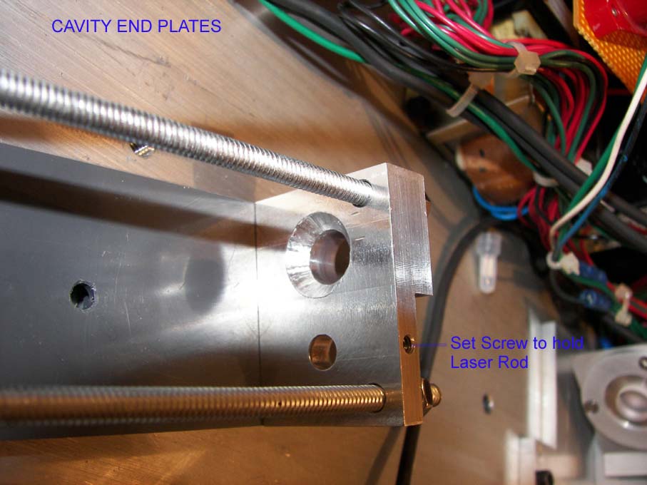
Cavity: design 1.25 inch 1/8 wall aluminum tube polished then compressed to ellipse with minor axis at 1.14 inch. Foci separation set to 0.75 inch. 3.65 inch long cavity. Rod end holders 0.5 inch thick with 0.23 inch thick at rod. A aluminum foil plug and set screw will hold Nd:yag rod in place. Length with rod holders: 3.65+.23+.23 = 4.11 inch. Use of aluminum reflectors will require more pump energy due to the lower reflection efficiency for pump wavelengths needed for Nd:yag. Based on reflectivity of 60% and the eccentricity of 0.54 then this cavity efficiency would be 25%. Since it takes four times the input energy because of the cavity efficiency of 25%, having high reflectivity is very important in ellipse cavities to improve efficiency. For this cavity eccentricity, 100% reflectivity would bring cavity efficiency to 60%. To improve cavity efficiency to 90% would require eccentricity at 0.15; almost a round tube with the rod and lamp very close together. In this case due to the use of air-aluminum cavity, the rod separation was more important both from a mounting perspective as well keeping the rod away from the hot flashlamp.
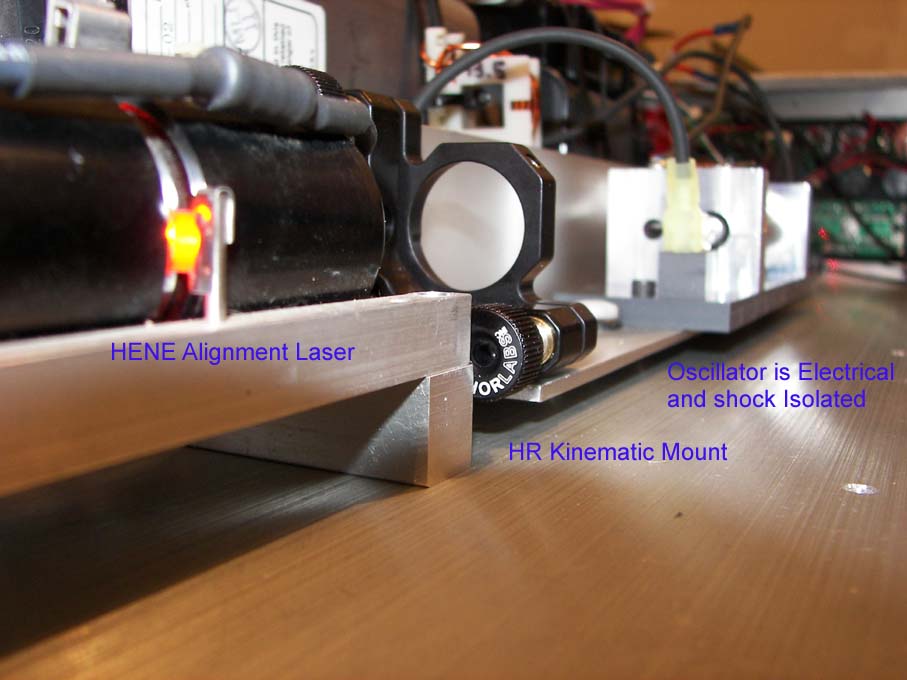
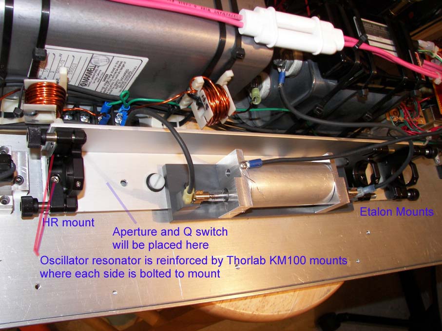
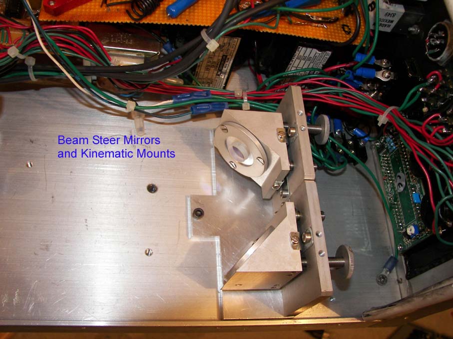
hyago1.jpg hyago2.jpg hyago3.jpg hyago4.jpg Alignment laser and oscillator resonator. The resonator L bracket is reinforced by having the 8-32 cap screws with nut plates bolt both sides to the Thorlabs KM100 mounts. The PVC base plate was cut to 0.3 inch thick to set the oscillator rod to the 1 inch height of the KM100 mounts. The beam center line is 35.5 mm above the chassis due to the nylon/grommet isolation.
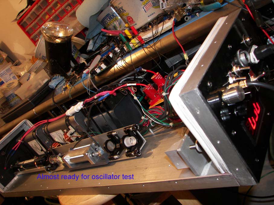
Images of oscillator setup for test:
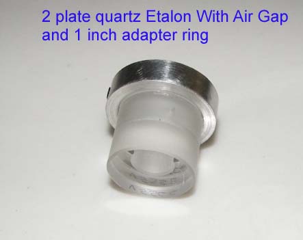
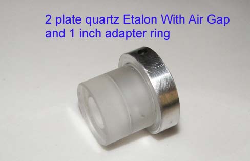
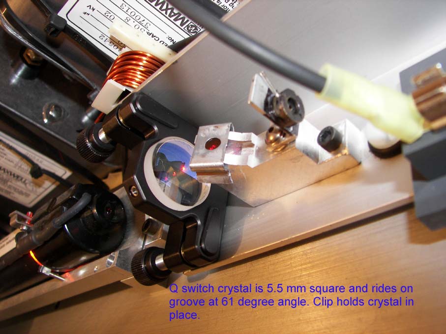
etalon1.jpg etalon2.jpg hyosc1.jpg hyosc2.jpg hyosc3.jpg hyosc5.jpg hyosc6.jpg hyosc7.jpg hyosc8.jpg hyosc9.jpg
FIRST TEST:
It was determined during test of oscillator that more input joules would be
needed. Part of the issue is lower efficiency of the cavity and higher losses
at the OC etc. The laser produced the same power with either the
At 20j of electrical pump, the laser produced 29mj non-q-switched multimode.
At 30j of electrical pump, the laser produced 102mj.
Iris diaphragm 12mm diameter and 4mm thick for spatial mode control. Iris set for 1.1 mm for TEM control.
At TEM00 mode the laser only produced 7mj non-q-switched
Q switch output generally is about half that value so it would be around 3mj.
![]()