Home Return to Main Page
Notes on
a Ruby MOPA 2 Arrangement
The purpose for this
arrangement is to generate holographic light.
reflect2.gif
Diagram of single beam reflection hologram setup
Tank lasers were setup in a MOPA
(Master Oscillator and Power Amplifier) configuration. This arrangement is used
inorder to get a cleaner beam and also obtain power for good development of
film. Although these lasers are used by some to burn things and with
modifications can be setup to do just that although with limitations as you
reach a point when you burn antireflection or surface pit the optics. This
arrangement with the specified below power supply is capable of generating
multimode output in excess of 500 mj. Instead the object is to reduce the power
of the Master Oscillator to keep other spatial and longitudinal modes from
developing. The desire is to have a good TEM00 spatial mode and a good
coherence length. Result was a laser that produced good sharp holograms but
dim. This also may be due to developer I was using at the time.
The tank laser has many good
features for use in designing a Holographic laser:
Q switch for short pulse high peak
power, resonant reflectors improving coherence length in addition to a folded
resonator about 33.5 cm long (compact and a good length), good prism optics,
Porro and rotating prism make easy alignment for a plane-parallel resonator.
Half cavity for good heat dissipation.
MOPA Head Arrangement
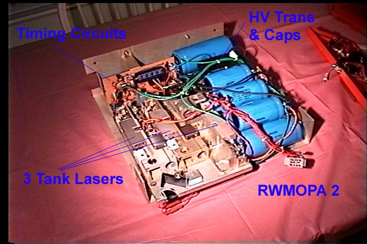
Three surplus tank lasers are
arranged side by side. See Picture and Diagram.
rw_mopa2.gif
Diagram of mopa version 2
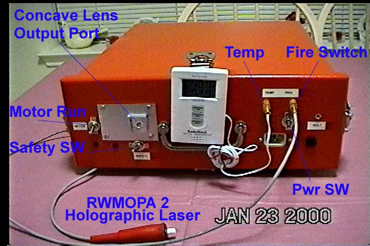
rw2a.jpg
Picture of external case
rw2b.jpg
Picture with front cover off
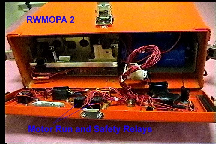
rw2c.jpg
Picture with chassis out of case
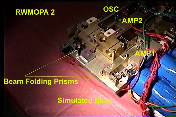
rw2d.jpg
Close up of mopa
Two 90 degree angle prisms are
also used to fold the beam path to the power amplifiers. The Power amps have
been modified by enlarging the 6mm bores for the flashtube to accommodate the 9
mm bore of the larger tubes. Each power tube is powered by 800 joule electrical
input. The Master Oscillator is powered by the standard 4mm tube at 200 joule
electrical input.
The Oscillator resonator has a
variable aperture inserted for TEM00. Set at 1 mm the TEM00 mode is about 5 mj
output. The delay to fire for the oscillator flashtube can be adjusted to fine
tune the laser input just above threshold to improve transverse and axial
modes. The Resonant reflector improves the longitudinal mode selection. But due
to not keeping the temperature finely controlled, this also can still be
problematic. Basically I mounted the lasers on a large aluminum slab ½ inch
thick mounted on top of a large inverted heatsink with radiator fins. The
combination of a large latent heat sink of the slab and radiation of the
radiator helps keep the unit somewhat temperature stable using ambient
environmental cooling and firing the laser once every 25 minutes. I did not want
to use cooling fans due to dust contamination or other cooling/heating methods
as I wanted to basically keep it simple. One of the thermister in the cavity is
used in parallel with one mounted on the slab. This is plugged into a Radio
Shack temperature module for reference. The power amplifiers due to their rod
lengths basically double the output for each stage passed. By tuning the delay
to fire for the flashtube I was able to get 2.3x output from each stage.
Yielding a final output of 25-30mj, but eventually with the oscillator running
at a higher level and a slightly larger aperture the oscillator yielded 8 to 10
mj and the amps brought the power to 54mj.
Alignments
Inorder to obtain the gain desired
it is important to align the ruby’s C-Plane axis of both the oscillator and
amplifiers. All should be in the same plane either vertical or horizontal.
Since Porro prisms are used it is important to keep it either vertical or
horizontal inorder to keep good polarization. The E field will be perpendicular
to the C axis.. Due to this arrangement it will also create the most absorption
when firing the oscillator through the unpowered amplifiers. I found that a
12mj beam will emerge from the first pass of the two amp stages at about 1mj
power. That same test with both amps powered up will yield 63 mj. Inorder to
align the prisms for the beam path, I had to operate one amp just to keep from
losing the signal while aligning with alignment paper. Care must be taken to
allow for 1/2 times the TEM00 beam size clearance on any optic as not to create
additional diffraction (the 2x to 3x diameter beam size aperture rule). In our
case I centered the beams within the rod.
Beam Quality
I found it hard to eliminate the
other TEM modes from the laser perhaps due to rotating mirror alignment during
pulse buildup time. Using a 1mm aperture, I managed to get TEM00. Getting
precise alignment centering of the Aperture helped due to the HR being a porro.
Which by the way I had to replace by finding another one from another tank
unit. I choose the best optic and motor bearing quality laser I had for my
oscillator. But found that I was getting two beam modes that looked like
rectangular tem01 mode. But instead it turned out to be a bad tem00 mode due to
the roof line of the porro was poor. I salvaged the best one I could find out
of my litter. Aligned up the unit and got good TEM00 or as best as it gets with
these units. Beam pulse width was measured at about 40 nsec duration and in the
single pulse mode. With the resonant reflector setup and a MOPA arrangement , I
found I could get Holographic scene depth of around 4 inches by estimate using
the single beam reflection method which implied an 8 inch coherence length.
Again this is just a rough guess at it. I was impressed with the sharpness
of the image, not impressed with the overall dimness of the hologram as I
had to use sunlight to see it well. I assumed power levels was the issue and
never investigated developers as an issue. Overall this setup made for a
good holographic laser without much expense invested.
Q Switching and Firing Control
The Q switch motor was ran
backwards to allow for the correct timings of firing the power amps and Master oscillator
flashlamps due to a longer flash pulse to keep the flashtubes at a lower
percent of explosion limit. Also the motor was voltage regulated to run at
30,000 rpms. Yielding 2msec between trigger pulses. The Osc was adjusted for a
1.1 msec delay. The power amp was adjusted for a 1.2 msec delay. This was
accomplished by using pairs of 556 timers in their own cascaded arrangement. An
additional 555 timer controls a relay for the motor run time of about 2
seconds. Firing protection is accomplished by using a manual safety switch.
With the switch in the closed (Safety off) position it supplies the 300vdc for
the primary trigger circuit. When the trigger fire momentary is closed this
starts the 555 motor/relay. Allowing for motor surge to settle, 500 msec later
a 556/relay in series with the safety manual switch completes the path to
charge the trigger primary coil caps. Then another 556/relay closes the
connection from the magnetic pickup (trigger timing pulses) 200 milliseconds
later. The Timing pulses are rectified and amplified/inverted by a transistor.
This then feeds the pair of 556 flashlamp timers. These 2 timers then fires
into 3 SCR/trigger circuits to dump the trigger primary power for HV triggering
at each flashlamp.
Oscilloscope of motor q switch
operation and output rwmopao.htm
timcir.htm Timing circuit used to control Q switch timing. Power supply and SCR trigger circuit/Series Injection Trigger Transformer circuits. The only circuit not show is the motor control/ relay circuits etc that are based on the same NE556 delay circuit but the output drives a relay to control the motor, and make connections for the firing /safety system.
Rotating prism has three reflections during rotation. 1st at the fire position, 2nd at the 144 degree position and 3rd at the 216 degree position. This should be kept in mind for firing timings.
Power Supply
Each amp is fed from a central 30kohm current limited fullwave diode bridge 850v transformer. Yield about 1150 volts fully charged. Each amp uses 3 450v 3900 ufd electrolytic capacitors in series with a resistor voltage divider. I used 2watt 500k carbon resistors across each cap to help keep the voltage within the limits and to provide a discharge path when the supply is turned off. The Osc uses 3 450v 1000 ufd caps. These 9 caps yielded the most compact arrangement. 3 HV diodes and 2 switches are used to provide three separate legs allowing to turn on/off which optical amp power supply and it‘s laser. The diodes are used to prevent one bank of caps from discharging into another laser through the common power supply. A 300 volt supply is created from a second transformer/Fwbridge. This dumps into a 400v cap to supply enough energy to fire the all the trigger SCRs. Each flash tube is arranged in a series injected circuit. A highvoltage trigger pulse from the secondary of the in series transformer/inductor provides the flash start. A SCR shorts a trigger cap into the trigger primary.