Home Return to Main Page
DYE Q SWITCH RUBY LASER Version 5.
Specific holographic design
includes:
The configuration is a MOPA
arrangement. Oscillator is normally operated at various amounts above threshold
and uses an aperture for transverse mode selection. Axial mode selection is
accomplished by use of resonant reflector and dye Qswitch. Resonant reflector
will reduce to 8 modes or less and dye Qswitch (saturable absorber) will reduce
further to 1 or 2 modes. Power amplifiers increase output to approximate 250 to
350 millijoules depending on pulse quantity. Changing Oscillator power and
adjusting dye concentrations allowed 1 to 4 pulses and therefore gave a wider
range of possible output.
rwmopa5.gif Diagram of RW-MOPA ver 5.
Image6.gif Oscilloscope of output.
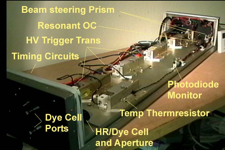
rwmopa5.jpg
Picture of ver 5 laser head. 250-350 mj holographic.
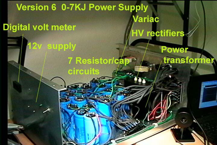
pw65.jpg Power supply used in version 5 and
6. Version 5 was 4300 joules. Version 6 was increased to 7kj and then
8kj.
dye3.htm Oscilloscope
output of RW-MOPA 5 with dye cell adjusted for multi-pulse.
Q switch pulse from oscillator.
The flashlamp pulse is approximately 700-800 usecs long. The Q switch pulse
generally would occur at the 50 percent trailing gain point but in this case it
occurred near the 30 percent trailing edge. The circuit was critically damped
at A= 0.8 using 1180v at 933 ufd and 58 uh . Delivering 650 joules to an
EG&G FX-42C 7mm flashlamp at the oscillator. Explosion limit was at 41
percent. Delivery of pump is 280 electrical joules/cm3 to a 6.3x76mm rod in a
half-elliptical cavity. The resonator length is 77cm. HR is 3m spherical
concave and OC is a planar 2 plate resonant reflector type from tank OC. Beam
waist Wo radius = 0.538 mm. Aperture set at 1.2mm at HR due to the 16% increase
in mode size. Fresnel number is 0.67 at aperture. The resonator G is 0.75
The HR forms part of 8mm dye cell
with a 6.3mm dual AR coated window. I decide on DOTCI in ethanol as a q switch
formula. DOTCI was used to prevent mode locking. DOTCI absorption peak is 690nm
and importantly has a relaxation time of 1.7 nanosecs. Cryptocyanine in ethanol
had a absorption peak at 710nm and a relaxation time of 17 picoseconds. Crypto
dye is the dye of choice for passive mode locking with q switching. The reason
not to mode lock (create multiple picosecond pulses in a q switch envelope is
the main purpose here is to reduce the number of longitudinal modes. An
example, the broadband frequency gains like TI-sapphire lasers convert it's
large frequency bandwidth domain into femto-second short pulses in the time
domain due to mode locking. Likewise a fast dye is likely to mode lock and not
provide the slow pulse build time that reduces frequencies that oscillate from
the gain differences created by the resonant reflector. That slow build time or
larger number of cavity round trips allows the gain differences between axial
modes to increase and therefore will help produce a more dominate single mode
or two.
Adjustment of dye solution allows
for a large single pulse or two shorter pulses. Adjustment of dye solution also
affects location on the trailing edge of the pump cycle. By delaying the giant
pulse and allowing more round trips for the noise signal to build, further
improvement on axial mode selection occurs. Instead of reducing pump
(electrical input) and therefore gain to obtain this, dye concentration can be
increased. Power amplifiers were pumped to 380 electrical joule/cm3 with total
of 30cm or 12" single pass length. Optics from CVI laser. Dye from
Exciton. Inc. Series injection triggers and flashlamps from Perkin Elmer of
former EG&G. Ultrastable kinematic 1" optic mount threaded model KS1-T
using 1" SM1L10 lens tubes from Thorlabs Inc. yag Inc. machined all
enclosures and optical benches. Optical bench is 1"X 38"X 6"
6061 aluminum plate milled for various component heights and rubber shock mounted
on 1/2 x 10 x38 bottom plate. Rod, OC and cavity salvaged from tank surplus
market. Cavities milled to accept 7mm flashtubes instead of 4mm. 5000 joule
power supply and timing circuits engineered by yag Inc.
Image7.gif Dye Q switch
pulse output.
At 10ns sampling rate you can see
that the pulse is 50 nanoseconds long. A single 15-17mjoule TEM00 mode pulse
was produced from this oscillator. Output is as follows from amp 1, 2, 3, and
4. 38mj, 80mj, 140mj, 246mj. Oscillator exit beam was 1.2mm and at the end of
amp chain was 1.8mm.
Laser had 1 nanosec rise time
photometer and bnc connector for cavity pulse monitoring by digital storage
oscilloscope. Needed when adjusting DOTCI dye/ethanol ratios for single or
double pulse. Also built in two thermistors and a digital thermometer show
cavity and bench/etalon temp. Laser has a remote hand held fire switch which
TTL logical level fires timing circuits for flashlamp triggers. System uses
series injection transformers and scr firing switches. Ports are used for an
external HENE laser for optic alignment of the laser system.
I found that when adjusting the
resonator with a fixed position aperture over the HR, I would align the
oscillator but then when I had to reduce the aperture, I had to adjust the OC
by tilting it until I got good power level from the oscillator at the small
setting. The fixed position aperture was due to the barrel mount design of it
and the aperture also had the dual purpose of shielding the dye from the flashlamp
light of the tank cavities. A interesting note I found that during alignment I
found I had three reflections at the OC. One in the center and two reflections
that hit above and below the main one and appeared to originate from the AR
694vcoat window over the HR that formed the dye cell. This HR/window dye cell
is the most efficient method but later I decided to use a separate dye cell in
future versions.