Home Return to Main Page
Ruby Pulse Holography 2006
Rwmopa8 ruby laser has been running as a single
frequency TEM00 mode laser with 6mm beam size and 1.1 to 1.8 joule single pulse
output of 12-20nsec. The laser was capable of much higher intensities from a
power supply/flashlamp ability but was kept at this moderate level to reduce
chance of amplifier damage by keeping the peak intensity below 6-10j/cm2. When
needed, extra power can be applied. The amplifier rods due to negative lensing,
the higher they are pumped with power levels, the increased beam divergence
helps lower the beam power density automatically for higher output powers. But
due to the amps having 3/8 inch rods, eventually the spatial diffraction ripple
increases due to this aperture restricting size. Clean optics and enough
aperture for the beam passage through the amplifiers help minimize diffraction
ripple in the spatial beam but become unavoidable at higher levels due to rod
size.
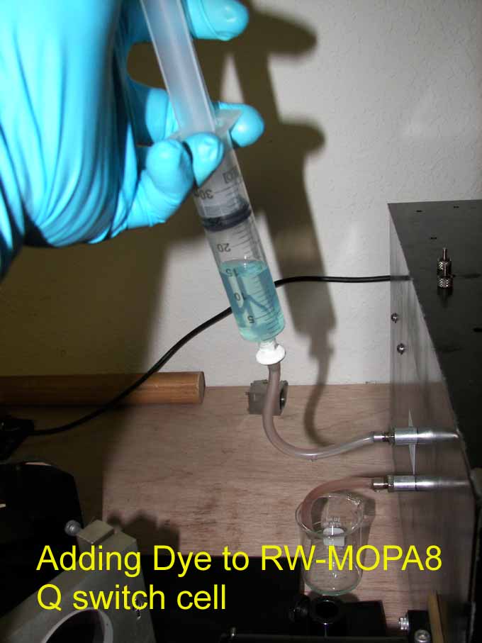
Adding dye/ethanol to q switch and monitoring with oscilloscope to make sure single pulse before a hologram session and the output energy level is verified.dyecell.jpg
More info on laser.ruby.htm
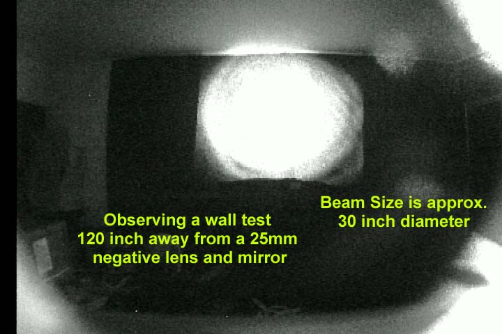
Projected Wall test of near full power laser output. wall.jpg
Changes to old holography setup. holoreflect3.gif
link to original setup info holosetup.htm
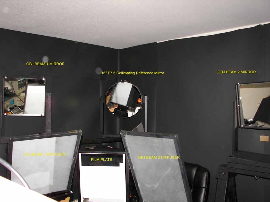
Setup with new 16 inch paraboloid mirror. At F7.5 and 119.84 inch focal length the overall path lengths were measured at 156 inch for the reference beam and 157" for the object beams. mirrors.jpg
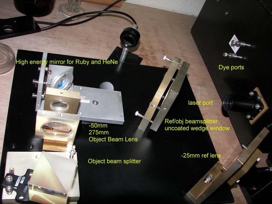
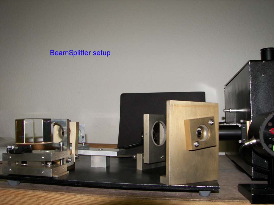
New configuration of beam splitter uses first beam splitter for ref and obj and second BS for obj split. The beam splitter setup was designed to insure a good reference beam quality by using only a single surface reflection and adding versatility to the beam ratio ability by inserting various lens which changes the beam ratios to improve fringe contrast. The target ratio was set to a 3/2; reference/object intensities .
beamsplitter3.jpg beamsplitter4.jpg
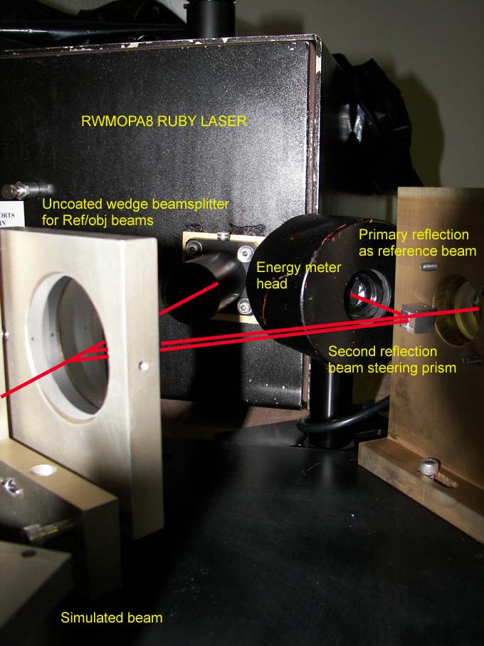
Picture of energy meter sampling of output beam. Secondary reflection from reference splitter is caught instead of wasted to allow energy output measurement. beamsamp.jpg
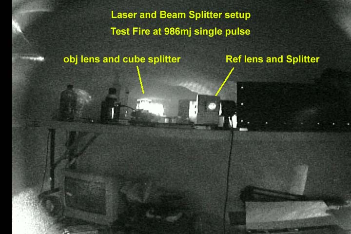
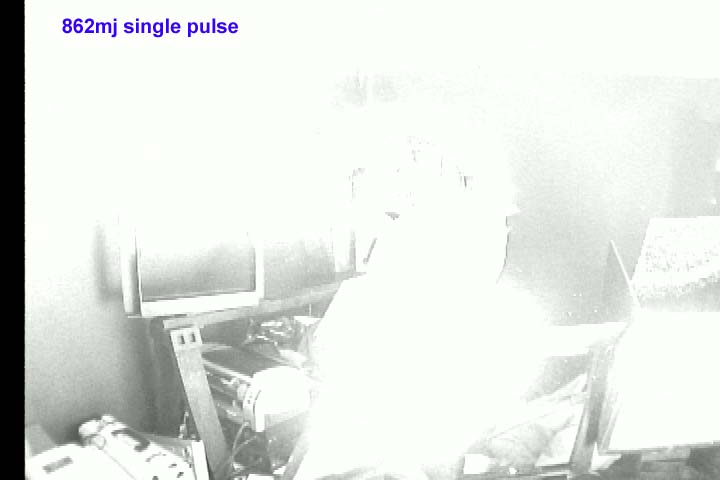
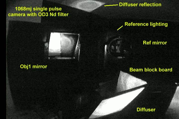
Picture of laser firing though beamsplitter setup using ccd camera with OD3 neutral density filter. testsplit.jpg
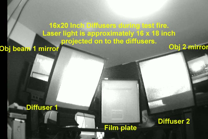
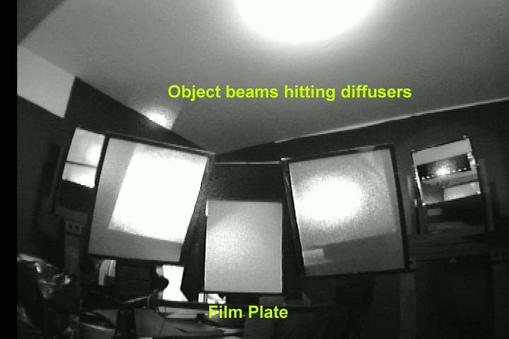
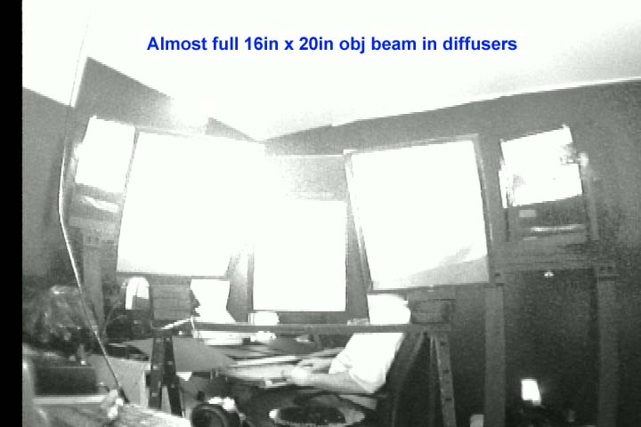
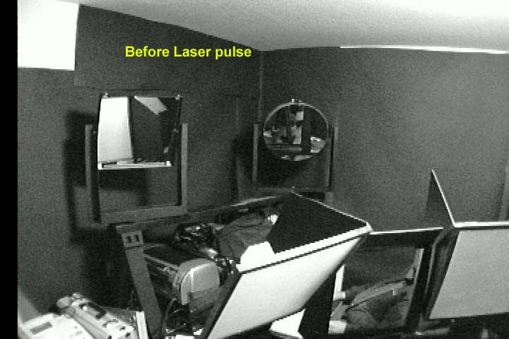
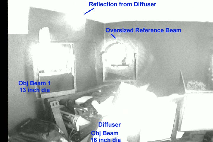
Diffusion screens during a test fire of the
holographic setup.
diff.jpg diff2.jpg obj1.jpg blast1a.jpg blast1b.jpg objm.jpg
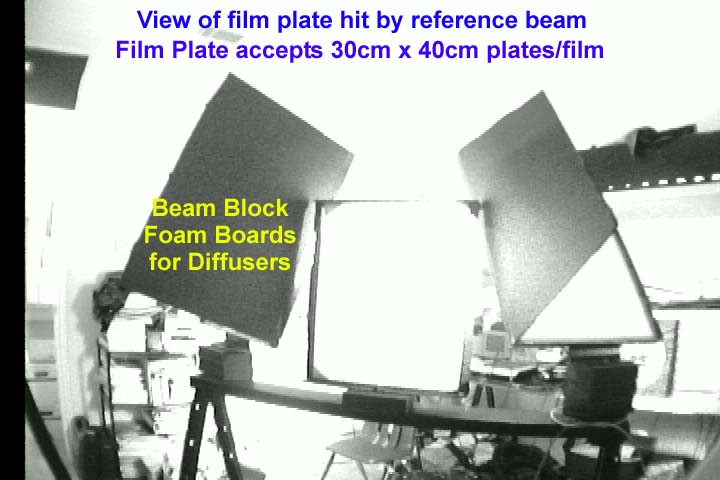
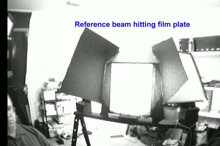
Reference beam coverage of film plate during test fire. ref.jpg
Image of reference beam at film plate with lower power to better visualize coverage. ref2.jpg
Image of reference beam at parabolic mirror . refp.jpg
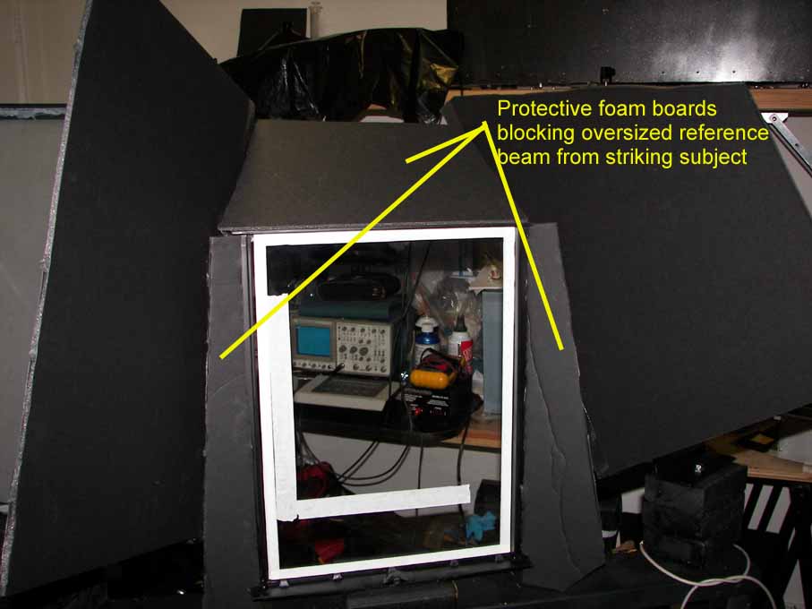
One technique used to shield subject from the reference beam is asking subject if they can see a red light through the film plate is the hene alignment beam source and the stool is raised until they are not able to see the source light. Based on distance from film plate and height the reference beam should not be able to be seen. The beam boards will block any chance of the beam over reaching the film plate and hitting the subject. In order to fill a 30cm x 40cm film plate the reference beam is set to 18 inch diameter. bref.jpg
Even though the laser operates in single frequency
mode and the coherence length should be around 3-6 meters or better, the path
length differences between obj and reference should be less than half for best
result. Also based on the oscillator resonator length the ideal distance of 2L
was calculated so that the maximum intensity of the interference fringe on the
plate would be closer to the 2L multiple path length, if a second mode should
develop. The worst case would be odd multiple of L path length. In this case
the path lengths were brought closer to the 10L where L was 22.42 inches of
effective resonator length. 10L was 152.58 inch beyond the laser since
amplifiers and other beam mirrors inside rwmopa8 made for an additional 71.62
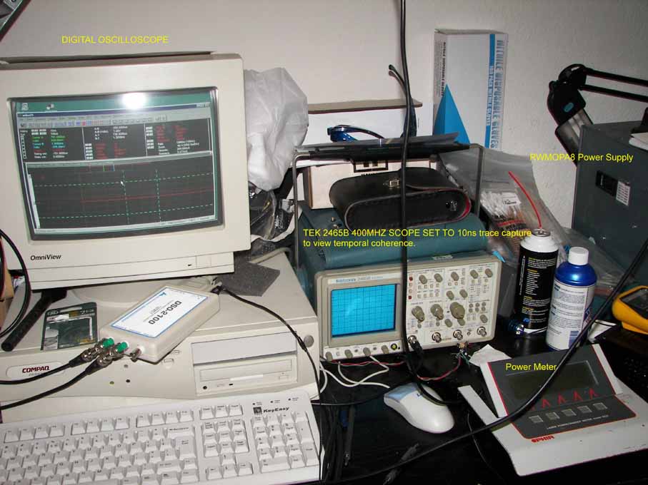
inch laser internal path length. A Tektronix 2465B analog 400mhz scope was used
to analyze the pulse shape to see if mode beating occurred. It was found to
only occasionally develop a second mode based on clean pulse modulation
harmonics present on the pulse envelope. With two modes and L length of 22
inches, this would mean that the coherence length at most would drop to 22
inches. If the second mode was at the same intensity but instead was found be
no stronger than 50% of the fundamental mode and generally around 5% of the
single mode amplitude. 80 percent of the test shots showed no pulse envelope
modulation indicating single mode laser shots.
The ruby rods were setup with c plane horizontal so
the output is vertical E field polarization this means S polarized for beam
steering mirrors inside the laser and for beam splitters and mirrors. This is
how normal optical bench type setup can be done to minimize the polarization
angle of the two beams arriving at the film plate since the beam arrive in a S
polarized orientation. The main object mirrors and reference paraboloid mirror
in this setup are tilted downward and the vertical polarized beam is now a P
polarized beam due to the now vertical (downward steering of the beams) and the
angles will effect the fringe maximum. Unfortunately this setup has both
horizontal and vertical beam steering. So one could evaluate which polarization
orientation would produce less possible angle between object beam and reference
beam. The laser was built with vertical laser polarization and was kept as
default but noted as an issue of concern. Calculations in this setup with a
general idea of 25 degree P polarized incidence of the reference beam to the
film plate and the film plate at a 5 degree tilt toward the subject, 25-5 = 20
degrees polarization angle and the fringe visibility due to polarization was
calculated in excel as =cos(20*pi()/180) or about 94 percent.
Beam splitter 1 used a clear wedge window for
reference with a calculated uncoated S polarized at 30 degrees of about 6
percent. Secondary surface 6 percent was blocked Care was taken to make sure any
secondary reflections were blocked and additionally the laser and splitters are
mounted overhead.
Additionally the setup allowed different lens to be
used for object and reference beams to control beam ratio intensities. The
reference beam was spread further to give more even illumination.
The object beam was fixed with a -50mm and 275mm
telescope at 54mm separation with some adjustment to separation.
The following reference lens gave these results:
-25mm below 1 to 1 ratio as measured at film plate.
-30mm around 1 to 1 ratio
-38.6mm around 3 to 4 to 1 ratio.
Two Thorlabs DET210 detectors with ND filters and a
digital storage oscilloscope were used to record the beam intensities and
ratios in the setup. test.jpg
The -30mm reference lens gave a very smooth
reference beam and maximum contrast for the fringes with ratios approaching 1
to 1. Agfa 8E75HD film was used with about 30uj/cm2 exposure level. A 1 to 1.3
joule single laser pulse gave moderately bright sharp images with additional
film developing to OD2.0 using the SM-6/Pyrochrome beach method shifting the
playback frequency from 694nm to around 600nm giving a nice bright orange look.
For the best in image quality the laser must produce a single pulse. Multiple
pulses with 100s of microsecs between them gave holograms of lower quality due
to interferometer like effects.
The object beam and reference beam have their own
expanding lenses, so the object beam lens focal length can be reduced to allow
more subject area to be illuminated without getting too high of a beam ratio.
The setup with tight object beams approaches 1 to 1 ratio the wider object
beams move the ratio closer to 2 or 3 to 1 if a larger area is needed.
Measured and calculations showed the following:
Path length 157 inch to plate. Within 1 to 5 inches
of max temporal intensity of 2L.
Reference beam size at 16 inch paraboloid mirror
was 25 inches.
Diffusers at 127 inch with 16inch spot size.
Diffuser to subject was 13 inch and then 12 inches
to the plate
Reference lens to paraboloid mirror was 94 inch,
which is below the 119 inch focal length to yielding a slight diverging
reference beam. Reference beam size at film plate was 18 inch.
1/73 of the incident object beam on the diffuser
reflected to the film plate from the subject of fair skin and light clothing.
Energy at the film plate was roughly at 10 to 25uj/cm2 reference based on power
levels and 8 to 10uj/cm2 object lighting. The safety ANSI extended source MPE
was calculated at 500nanojoule/cm2 MPE times the extended source correction
factor in this setup (16 inch diffused spot size at 13 inches from subject)
500nanojoule/cm2 x 10098 = 5049 microjoules/cm2. At 1 joule level, object beam
1 had a density of 800 microjoule/cm2 incident on the diffuser and object beam
2 had a 160uj/cm2 level, either beam and in total was below MPE. Calculations
were made based on the beam energy of 800mj object beam energy at a viewing
dist of 13 inch from a 16 inch diffuser with the ANSI formula for MPE. These
calculations for an extended source, which uses the apparent visual angle
created, and Lambert's law adjusted with a Dp/2 term per ANSI when the viewing
distance is within 10 source diameters. The resultant energy is 56 times lower
than the allowable maximum energy that will produce a hazardous diffuse source.
Now this is not true of the reference beam whose average power is 20uj/cm2
which for ruby pulses is 40 times over the allowed MPE and will visually appear
as a small source. Therefore the subject's eyes must not be hit with the
reference light and proper care taken to prevent it by adjustment of subject
height so beam falls on chest. Use of transmission H1 master and H2 Reflection
technique helps to reduce this problem of using a direct reflection holographic
technique.
A comparison of film and reference angles etc is presented: http://www.holography.co.uk/hcon1hb1.pdf
According to this study using a single beam
reflection hologram, Agfa 8E75HD diffraction efficiency should be around 6 %
for a 21.5 degree reference beam and reversal bleaching. If instead the
rehalogenated bleach and 31 degree reference angle is used the efficiency could
be as high as 15%. Even though the diffraction efficiency is higher, about
twice, the apparent brightness at 694nm would be much less than a 600-625nm
playback from reversal beach shrinkage as much as 30 to 1.
Overall the quality of the hologram was good.
The brightness was moderate for the reflection volume hologram. The reference
illumination was smooth without hot spots. In the sun the image was sharp and
the graininess of the development was low to moderate. Good quality 30cm x 40cm
film and plates can be made with this setup.
![]()