All Rights Reserved
Reproduction of this document in whole or in part is permitted if both of the following conditions are satisfied:
1. This notice is included in its entirety at the beginning.
2. There is no charge except to cover the costs of copying.
DISCLAIMER
µMD1 is intended for use in hobbyist, experimental, research, and other applications where a bug in the hardware, firmware, or software, will not have a significant impact on the future of the Universe or anything else. While every effort has been made to avoid this possibility, µMD1 is an on-going development effort. We will not be responsible for any consequences of such bugs including but not limited to damage to the wafer FAB you picked up on eBay for $1.98 + shipping, financial loss from the use of 37 spools of ABS due to the office 3-D printer fabricating a part 25.4x too large in all dimensions, or bruising to your pet's ego from any number of causes directly or indirectly related to µMD1. ;-)Acknowledgment
Thanks to Jan Beck for selecting the chipKIT DP32 and writing and testing initial versions of the firmware and GUI. And for getting me interested in actually getting involved in this project. If anyone had told me six months ago that I'd be writing code in C, MIPS assembly language, and Visual Basic - and enjoying it (sort of) - I would have suggested they were certifiably nuts. ;-) Jan maintains the master GUI source code as well as slightly different versions of the firmware and a development blog on the overall project. And a version of the firmware providing basic readout of displacement on any Bluetooth wireless device with a terminal APP, or with a bit more polished presentation (though not the complete GUI) on Android devices, may be found on Jan's Web site. See that and more under "References".Introduction
This document provides assembly instructions for the minimal configuration to enable the SG-µMD1 V1.2 PCB to support the downloading of the bootloader and other firmware directly via MPLAB, or via USB.
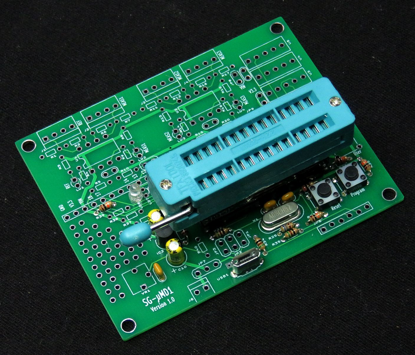
SG-µMD1 V1.0 PCB MPLAB Version with ZIFF Socket. V1.2 is Nearly Identical
The 28 pin SDIP ZIFF socket is plugged into a leaf-spring socket which is plugged into a machine-pin socket. The stack is glued together on the edges so that it easily plugs into the socket on the SG-µMD1 PCB. Installing a right-angle header for JP6 would be beneficial as a straight header blocks the Reset and Program buttons. Of course, the PIC32 can be plugged directly into the on-board socket.
All components are through-hole and except as noted in the detailed assembly procedure, should seat flush on the PCB. They shouldn't be suspended in mid-air swinging in the breeze. :) Most components are identified on the silk-screen and with only a few exceptions, the label won't be obscured when the part is installed.
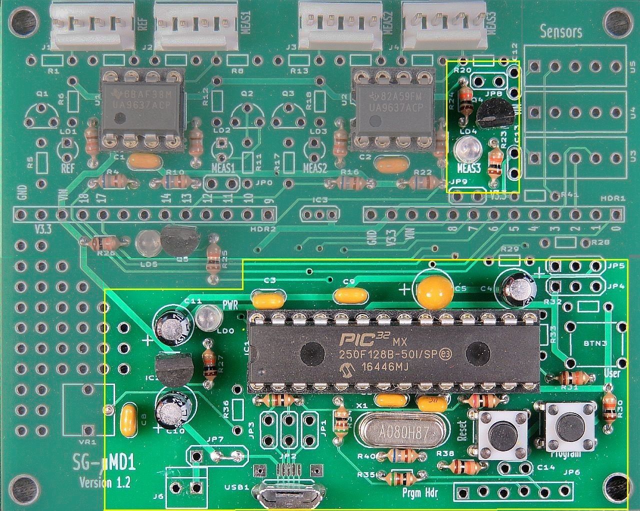
SG-µMD1 V1.0 Single Axis PCB shows the PCB populated with the parts for a single axis system without sensors. Only the parts below the headers are required for MPLAB and USB download support.
A low power soldering iron with narrow tip and thin (e.g., #22 AWG) rosin-core solder will be required. DO NOT even think about attempting this without suitable soldering equipment. It's well worth the investment. A Weller soldering gun or propane torch will not work. :) Rosin core solder is also essential. And while I'm quite confident that you never make mistakes, a means of component removal such as a de-soldering pump (e.g., SoldaPullt™) will be highly desirable. Screwing up component removal can easily ruin the PCB and is not covered under the unlimited limited warranty. :-)
Proper soldering technique will be such that the exposed solder on each pad should be shiny with a concave profile. It should not be a blob and just needs to fill the hole. Solder is not glue. Some excess solder doesn't hurt anything but looks unprofessional. A 10X magnifier may come in handy for inspection. Residual rosin can be cleaned off with isopropyl alcohol or an environmentally-friendly electronic solvent. However, leaving the rosin alone is also acceptable (if ugly).
Total assembly time should be well under two hours for someone proficient in fine soldering. Cutting component leads to 1/4 to 3/8 inch before installation will simplify soldering as the long leads won't be poking you in the face. :( :) Then trim flush after soldering.
The USB driver is NOT required for MPLAB, only a USB port or charger to provide 5 VDC power. CAUTION: If using a charger, confirm that its output is close to 5 VDC. This should always be true for those from name brands like Apple. But others that are non-genuine or counterfit may be all over the map.
Instructions for using MPLAB to download the bootloader are in the µMD1 manual (where you came from).