For contact info, please see the Sci.Electronics.Repair FAQ Email Links Page.
Copyright © 1994-2022
Reproduction of this document in whole or in part is permitted if both of the
following conditions are satisfied:
1. This notice is included in its entirety at the beginning.
All Rights Reserved
2. There is no charge except to cover the costs of copying.
DISCLAIMER
Although working on small audio and related electronics is generally
less risky than dealing with equipment like microwave ovens, TVs, and computer
monitors, devices that plug into the wall can still produce a very lethal
electric shock as well cause a fire from incorrect or careless repairs both
during servicing or later on. It is essential that you read, understand, and
follow all safety guidelines contained in this document and in the document:
Safety Guidelines for High Voltage and/or Line Powered
Equipment.
Improper repair of battery operated devices can also result in bad consequences for you, the device, and any equipment attached to it.
We will not be responsible for damage to equipment, your ego, county wide power outages, spontaneously generated mini (or larger) black holes, planetary disruptions, or personal injury or worse that may result from the use of this material.
However, if you can do the repair yourself, the equation changes dramatically as your parts costs will be 1/2 to 1/4 of what a professional will charge and of course your time is free. The educational aspects may also be appealing. You will learn a lot in the process. Many problems can be solved quickly and inexpensively. Fixing an old boombox to take take to the beach may just make sense after all.
This document provides maintenance and repair information for a variety of consumer electronic devices not covered by other documents in the "Notes on the Troubleshooting and Repair of..." series. Suggestions for additions (and, of course, correction) are always welcome.
You will be able to diagnose problems and in most cases, correct them as well. As most difficulties encountered with this type of equipment are mechanical, there is significant emphasis on dirt, lubrication, deteriorated rubber parts, broken doohickies, and so forth. With minor exceptions, specific manufacturers and models will not be covered as there are so many variations that such a treatment would require a huge and very detailed text. Rather, the most common problems will be addressed and enough basic principles of operation will be provided to enable you to narrow the problem down and likely determine a course of action for repair - or decide that replacement is indeed the better option. However, in many cases, you will be able to do what is required to repair a piece of equipment for a fraction of what would be charged by a repair center. Perhaps, you will even be able to revive something that would otherwise have gone into the dumpster - or remained in that closet until you moved out of your house (or longer)!
Should you still not be able to find a solution, you will have learned a great deal and be able to ask appropriate questions and supply relevant information if you decide to post to sci.electronics.repair. It will also be easier to do further research using a repair book or guide. In any case, you will have the satisfaction of knowing you did as much as you could before finally giving up or (if it is worthwhile cost-wise) taking it in for professional repair. With your new-found knowledge, you will have the upper hand and will not easily be snowed by a dishonest or incompetent technician.
If you are just getting started, you should refer to "Repair Briefs, an Introduction" for additional troubleshooting tips, recommended test equipment, suggested parts inventory, and other general information.
For general troubleshooting techniques, see the section: Some general references.
The How Stuff Works Web site has some really nice introductory material (with graphics) on a variety of topics relating to technology in the modern world. Of relevance to this document are articles on motors, power adapters, relays, batteries, etc.
Check out "Sam's Neat, Nifty, and Handy Bookmarks" (at this site) in the "Education and Tutorials" area for links to basic introductory material on electronics and other related fields.
Check with a multimeter on the AC volts range between any combination of user accessible parts - cases, antenna jacks, etc., and an earth ground like the third hole of a properly grounded outlets.
For the slight tingle case:
If you get stuck, sleep on it. Sometimes, just letting the problem bounce around in your head will lead to a different more successful approach or solution. Don't work when you are really tired - it is both dangerous and mostly non-productive (or possibly destructive).
Whenever working on precision equipment, make copious notes and diagrams. You will be eternally grateful when the time comes to reassemble the unit. Most connectors are keyed against incorrect insertion or interchange of cables, but not always. Apparently identical screws may be of differing lengths or have slightly different thread types. Little parts may fit in more than one place or orientation. Etc. Etc.
Pill bottles, film canisters, and plastic ice cube trays come in handy for sorting and storing screws and other small parts after disassembly.
Select a work area which is well lighted and where dropped parts can be located - not on a deep pile shag rug. Something like a large plastic tray with a slight lip may come in handy as it prevents small parts from rolling off of the work table. The best location will also be relatively dust free and allow you to suspend your troubleshooting to eat or sleep or think without having to pile everything into a cardboard box for storage.
Another consideration is ESD - Electro-Static Discharge. The electronic components in a some devices like cassette decks, Walkmen, and portable phones, are vulnerable to ESD. There is no need to go overboard but taking reasonable precautions like not wearing clothing made of wool that tends to generate static. When working on larger devices like cassette decks, get into the habit of touching a ground like the metal chassis before touching any circuit components.
A basic set of precision hand tools will be all you need to disassemble and perform adjustments on most consumer electronic equipment. These do not need to be really expensive but poor quality tools are worse than useless and can cause damage. Needed tools include a selection of Philips and straight blade screwdrivers, needlenose pliers, wire cutters, tweezers, and dental picks. A jeweler's screwdriver set is a must particularly if you are working on compact equipment. For adjustments, a miniature (1/16" blade) screwdriver with a non-metallic tip is desirable both to prevent the presence of metal from altering the electrical properties of the circuit and to minimize the possibility of shorting something from accidental contact with the circuitry.
For thermal or warmup problems, a can of 'cold spray' or 'circuit chiller' (they are the same) and a heat gun or blow dryer come in handy to identify components whose characteristics may be drifting with temperature. Using the extension tube of the spray can or making a cardboard nozzle for the heat gun can provide very precise control of which components you are affecting.
Basic cleaning supplies include Q-tips (you may know them as cotton buds) for everything BUT the video heads on VCRs and other helical scan tape transports, chamois covered cleaning sticks (for video heads), lint free cloths or paper towels, water, and isopropyl alcohol (preferably 91 percent medicinal grade or better).
For info on useful chemicals, adhesives, and lubricants, see "Repair Briefs, an Introduction" as well as other documents available at this site.
Three wire grounded soldering equipment is recommended but I do not consider it essential for this type of repair work. However, a temperature regulated soldering station is a really nice piece of equipment if you can afford it or happen on a really good deal.
I consider fine gauge rosin core solder (.030 or less) to be best for most applications (e.g., Ersin Multicore).
A vacuum rework station is not needed unless you are removing your soldered in 1,500 pin Intel P8!
CAUTION: You can easily turn a simple repair (e.g., bad solder connections) into an expensive mess if you use inappropriate soldering equipment and/or lack the soldering skills to go along with it. If in doubt, find someone else to do the soldering or at least practice, practice, practice, soldering and desoldering on a junk circuit board first!
However, there are times where soldering is more convenient. Use of the proper technique is critical to reliability and safety. A good solder connection is not just a bunch of wires and terminals with solder dribbled over them. When done correctly, the solder actually bonds to the surface of the metal (usually copper) parts.
Effective soldering is by no means difficult but some practice may be needed to perfect your technique.
The following guidelines will assure reliable solder joints:
Practice on some scrap wire and electronic parts. It should take you about 3 minutes to master the technique!
See the document: Troubleshooting and Repair of Consumer Electronics Equipment for additional info on desoldering of electronic components.
One approach that works in some cases is to use the mating socket to stabilize the pins so they remain in position as you solder. The plastic will still melt - not as much if you use an adequately sized iron since the socket will act as a heat sink - but will not move.
An important consideration is using the proper soldering iron. In some cases, a larger iron is better - you get in and out more quickly without heating up everything in the neighborhood.
A DMM or VOM is necessary for checking of power supply voltages and testing of sensors, LEDs, switches, and other small components. This does not need to be expensive but since you will be depending on its readings, reliability is important. Even a relatively inexpensive DMM from Radio Shack will be fine for most repair work. You will wonder how you ever lived without one! Cost: $25-50.
Unless you get deep into electronic repair, a high bandwidth oscilloscope is not required. However, a relatively inexpensive 5 or 10 MHz dual trace scope is very handy and you will find all kinds of uses for it. Such a scope should cost less than $150 on the used market.
There are several specific pieces of test equipment that you may already own which are required depending on the devices being fixed.
Audio equipment:
If you intend to test phonograph (e.g., vinyl) or low level signals from tape heads, the amp should have magnetic phono level (average of 2 to 5 mV which is equivalent to -54 dBV to -46 dBV) in addition to line level (CD, DVD, tape, etc., average of 250 mV, peak of 2 V) inputs.
Video games, cable boxes, and other video sources:
Telephone equipment:
Parts list:
For each phone line:
Construct the following circuit for each line and attach to the appropriate color terminals/wires of the modular jack:
                           10K            Green LED
Line 1:     (Green) o------/\/\-----+--------|>|-------+------o (Red
Line 2:     (Black)                 |  Wiring Correct  |        (Yellow)
Line 3:     (White)                 |                  |        (Blue)
                                    |      Red LED     |
                                    +--------|<|-------+
                                     Reverse Polarity
Note: Polarity of Tip and Ring are reversed with respect to the wire colors because of swap that occurs using the RJ11 extension cord.
Mount the LEDs in holes drilled in the plastic cover of the modular jack (making sure they clear the base when the cover is screwed down).
To test old style 4 prong phone jacks, use an adapter on the end of the RJ11 extension cord.
Correctly wired lines will light up green, reverse polarity will be red, dead line will be dark, line-in-use will be dark or nearly dark. If you catch a line that is ringing. both LEDs will flicker.
Putting just the LED portion (leave out the resistor) of this circuit in *series* with the phone line will implement an off-hook (in use) indicator.
Note: the sections on loudspeakers, cameras, and watches have additional 'getting inside' info.
Manufacturers seem to take great pride in being very mysterious as to how to open their equipment. Not always, but this is too common to just be a coincidence.
A variety of techniques are used to secure the covers on consumer electronic equipment:
These will often be of the Philips variety. (Strictly speaking, many of these are not actual Philips head screws but a slight variation. Nonetheless, a Philips screwdriver of suitable size will work on them.) A precision jeweler's screwdriver set including miniature Philips head drivers is a must for repair of miniature portable devices.
Sometimes, you will find Torx or a variety of security type fasteners. Suitable driver bits are available. Sometimes, you can improvise using regular tools. In the case of security Torx, the center post can usually be broken off with a pair of needlenose pliers allowing a normal Torx driver to be used. In a pinch, a suitable size hex wrench can substitute for a Torx driver. Places like MCM Electronics carry a variety of security bits.
Don't force anything unless you are sure there is no alternative - most of the time, once you determine the method of fastening, covers will come apart easily. If they get hung up, there may be an undetected screw or snap still in place.
The most annoying (to be polite) situation is when after removing the 18 screws holding the case together (losing 3 of them entirely and mangling the heads on 2 others), removing three subassemblies, and two other circuit boards, you find that the adjustment you wanted was accessible through a hole in the case just by partially peeling back a rubber hand grip!
When reassembling the equipment make sure to route cables and other wiring such that they will not get pinched or snagged and possibly broken or have their insulation nicked or pierced and that they will not get caught in moving parts. Replace any cable ties that were cut or removed during disassembly and add additional ones of your own if needed. Some electrical tape may sometimes come in handy to provide insulation insurance as well.
Do not be tempted to use compressed air!
I would quicker use a soft brush to carefully dust off the circuit boards and power supply. Work in such a way that the resulting dust does not fall on the mechanical parts.
For intricate mechanisms, using compressed air could dislodge dirt and dust which may then settle on lubricated parts contaminating them. High pressure air could move oil or grease from where it is to where it should not be. If you are talking about a shop air line, the pressure may be much much too high and there may be contaminants as well.
A Q-tip (cotton swab) moistened with politically correct alcohol can be used to remove dust and dirt from various surfaces of the deck (in addition to the normal proper cleaning procedures for the guides, rollers, heads, wheels, belts, etc.)
Try to locate the part with a bright light without moving anything. You may have gotten lucky (yeh, right). Next, over an area where a dropped part will be visible (not a shag carpet!), try any reasonable means to shake it loose - upside down, a little gently tapping and shaking, etc. A hard surface is better in some ways as you might hear the part drop. On the other hand it may bounce into the great beyond.
If this does not work, you have two options:
To prevent this sort of thing from happening in the future you will no doubt be much more careful. Sure you will! Some suggestions to prevent ejection of an E-clip, split washer, or spring into the great beyond:
Looking at the top of the deck such that the tape heads are at the bottom:
Play-only transports such as found in car cassette decks and Walkmen do not need an erase head. Autoreverse play-only decks often do just shift the position of the playback head a fraction of a mm depending on playback direction to line up with the tracks and interchanges the connections for L and R channels.
Clean the polished surfaces thoroughly (DO NOT use anything abrasive!).
Qtips and alcohol (91% medicinal is ok, pure isopropyl is better. Avoid rubbing alcohol especially if it contains any additives) can be used everywhere EXCEPT on the rotating heads of VCRs and camcorders (and other helical scan devices like 8mm and 4mm (DAT) storage drives) - see the document: Notes on the Troubleshooting and Repair of Video Cassette Recorders for detailed procedures on cleaning of video heads - you can destroy the most expensive part of your VCR by improper cleaning techniques. Dry quickly to avoid leaving residue behind. Sometimes good old fashioned water (just a damp cloth) will work better on sugar based gunk and other kids' grime.
Cleaning may get your machine going well enough to get by until any replacement rubber parts arrive.
Things to clean:
(Some of these components may not be present in your particular equipment).
Clean the pinch roller (presses against the capstan in play and record) until no more black stuff comes off. Use as many Qtips as necessary.
If the pinch roller is still hard and/or shiny or has a cracked surface, it will probably need replacement. Many are available from the sources listed in the section: Recommended parts suppliers.
Also, the idler assembly includes a slip clutch. If this weakens, the idler may not have enough force to press on the reel table edges.
Note that on some equipment like dual cassette boomboxes and telephone answering machines, the belt(s) may follow a highly circuitous path - make a detailed diagram!
Any belts that appear loose, flabby or do not return instantly to their relaxed size when stretched by 25% or so will need to be replaced and may be the cause of your problems. Belts cost about $.30-$2.00. Meanwhile, the belts will function better once they are cleaned, maybe just enough to get by until your replacements arrive.
A note about alcohol: Some people have suggested that certain alcohol may attack some types of rubber used in these mechanisms. This is certainly true if the rubber is already deteriorated but I have not seen this on rubber that is just dirty, not deteriorated as long as the rubber is not allowed to soak in the stuff! However, Windex (window cleaner) has been suggested as a better alternative.
NEVER, ever, use WD40! WD40 is not a good lubricant despite the claims on the label. Legend has it that the WD stands for Water Displacer - which is one of the functions of WD40 when used to coat tools for rust prevention. WD40 is much too thin to do any good as a general lubricant and will quickly collect dirt and dry up. It is also quite flammable and a pretty good solvent - there is no telling what will be affected by this.
A light machine oil like electric motor or sewing machine oil should be used for gear or wheel shafts. A plastic safe grease like silicone grease or Molylube is suitable for gears, cams, or mechanical (piano key) type mode selectors. Never use oil or grease on electrical contacts.
Unless the unit was not properly lubricated at the factory (which is quite possible), don't add any unless your inspection reveals the specific need. Sometimes you will find a dry capstan, motor, lever, or gear shaft. If possible, disassemble and clean out the old lubricant before adding fresh oil or grease.
Note that in most cases, oil is for plain bearings (not ball or roller) and pivots while grease is used on sliding parts and gear teeth.
In general, do not lubricate anything unless you know there is a need. Never 'shotgun' a problem by lubricating everything in sight! You might as well literally use a shotgun on the equipment!
Use a small demagnetizer designed for a tape deck or cassette deck. See the section: Homemade audio tape head demagnetizer if you don't have one or don't want to buy one. However, do not use anything that might be too powerful or a bulk tape eraser which would certainly be too powerful.
Make sure the tip is covered with a soft material to prevent damage to the finely polished surfaces in the tape transport.
The tape deck should be off (unpowered) during this process. (Strictly speaking, this doesn't really matter but it's just safer that way.)
Turn power on to the demagnetizer when a couple of feet away from the unit. Then, slowly bring it in close and slowly go over all surfaces of anything that the tape contacts or comes close to in the tape path. The key word here is **slowly**. Move fast, and you will make the magnetic fields stronger. When finished, slowly draw the demagnetizer away to a distance of a couple of feet before turning it off.
Adjust the number of turns and input voltage for desired strength. How strong should it be? A direct comparison with a commercial unit would be best but when in close proximity to a steel surface, you should be able to feel the 120 Hz attraction but it shouldn't jump out of your hand! Sort of like "Use a pinch of salt you will know how much" :-)
(From: Steven L. Bender (buqu35d@prodigy.com).)
You need a power transformer about 3" in each direction, can be like a low voltage 12 volt / 3 Amp unit or rated higher. Remove end bells if any, remove all the metal laminations (break the first one, yank it, and the rest will come easier). Re-insert all the metal laminations facing in the same direction, with the "E" all pointed the same, re-glue, varnish, or whatever. Connect AC Plug to the Primary, then insulate the whole works with Plastic tape and outre layer of Duct tape. After insulating it with several layers of tape - Instant Bulk Eraser.
WARNING: Do not apply power for more than 60 seconds at a time! (It will get hot and burn your hand after two minutes.)
I had one of those for some years, but accidentally left it plugged in, (pulled the wrong wire out of the 6 to 1 outlet box) and after a few minutes, it smelled and was too hot to touch, and made a nasty noise as the copper started to melt... (Sounds Effects of Liquid Krell Metal in the distance...., Forbidden Planet - Paramount, 1956).
Luckily I didn't walk out, another few minutes and it would have caught fire..
I am not liable for any personal, profession, or consequential damages from use of this information !!!
(From: Steve Walz (rstevew@armory.com).)
Use a transformer and remove the EI core pieces and replace all the E's only in the same direction. Current limit it with a wire-wound resistor so it doesn't overheat and put a momentary pushbutton on it and a power cord to wall AC and insulate it so you don't shock yourself. Then place it so the open face of the E core pieces faces the tape or disk or whatever to be erased and push the button. Run it all over both sides of the tape or disk and pull the tape or disk away before letting up on the button if you wish to erase it. If you wish to magnetize a tool or such, simply let up on the button while the object or tool is still in contact with it. That's how that works! (You may have to do it a couple times before you catch the AC cycle at the peak! --- Sam.)
(From: Pat Swayne (me@patswayne.com).)
Here's a safety tip for your homemade bulk tape eraser: Use a small length of very thin solder as a fusable link. Place this as close to, but insulated from, the primary windings as possible, and pass the current through it. If the thing gets too hot, it will melt the solder and break the connection.
(From: Sam.)
It would have to get mighty hot for that to be effective but it's cheap enough. Of course, a thermal fuse or thermostat would be a more well controlled alternative.
Note that the required torque for the driven reel is much less for PLAY and REC compared to FF and REW as the capstan in contact with the pinch roller pulls the tape from the supply reel.
The most likely causes are similar for all of these symptoms. The driven reel and/or capstan is not turning due to:
If the cause is not immediately evident once the bottom of the transport is visible, try to observe exactly what is happening when you play a garbage tape or run the deck with no tape present. Look for broken parts or bits of parts that may have failed off.
If the transport shuts down shortly after entering any mode, check for a missing or stretched tape counter drive belt or a defective reel rotation sensor. The tape eating protection circuits are shutting down the unit improperly due to a lack of reel sensor pulses. A related symptom will be that the tape counter (mechanical or electronic) does not change during the period when the tape is moving.
If the logic is not properly controlling the various solenoids or other actuators in a 'soft touch deck', then a service manual will be needed to proceed much further.
A simple test to determine if azimith alignment is your problem is to record some music on your machine and immediately play it back. If this recording sounds fine but it sounds muddy on another deck, then improper azimith alignment is the likely cause.
If the recording is still muddy, your deck may have electronic problems like excessive bias (check to make sure you have selected the proper type of tape or bias setting), a worn record/playback head, or the heads or other parts may be magnetized (see the section: Tape head demagnetizing. However, dirty heads as well other mechanical problems can also result in weak muddy sound. See the section: General guide to tape deck cleaning and rubber parts replacement.
The best way to adjust azimith is while playing a recording that was made on a known good deck - commercial tapes are usually (but not always) a good choice.
WARNING: once you adjust the azimith, any tapes previously recorded on this transport may sound muddy. If you only record and play your own tapes on this deck, you may want to just leave it alone.
The azimith adjustment is usually a screw that pivots the record/playback head. It may be spring loaded and possibly fixed in place with a some Loctite or varnish. Often it will be accessible through a hole without removing any covers but not always. Look for it while in play or record mode in back of any holes (which you had no idea had a purpose until now). If there are no access holes, you will have to remove the loading door, cover, or front panel. Be sure you have the correct screw before turning wildly - others may affect critical height or simply be mounting screws.
Play a tape with lots of good highs - classical instrumental music or jazz are excellent. Now, simply set the azimith adjustment for best sounding and strongest high frequencies which should result in most natural sound. Go slow - a 1/16 of a turn is significant. Turn the screw back and forth and leave it in the best sounding position. Carefully put a dab of Loctite or nail polish on the screw to prevent it from moving.
The socket that the AC adapter or headphones plug into is often quite abused during normal operation. This can lead to broken solder connections where it joins the circuit board inside the unit. Test for this possibility by wiggling the plug without moving or flexing the cable itself. If the sound cuts in and out or the tape player starts and stops or the radio goes on and off, or the CD player resets or stops, then there is likely a bad connection here. Note: eliminate the alternate possibility that the AC adapter or headphone cable is bad by wiggling and tugging on the cable while holding the plug steady. Further verify that it is not simply a matter of dirt or grime interfering with a good connection.
The connections can be easily resoldered but you will need to open up the case using. Hopefully this will only require jeweler's screwdrivers and great care. (However, some Walkmen are constructed such that access to the interior is virtually impossible without a hand-grenade.) To repair the connections, use a low wattage iron and fine rosin core solder. Make sure you do not introduce any solder bridges. Try not to lose any of the microscrews.
First, confirm that the problem is not in your headphones, patch cables, or the remainder of your audio system - try an alternate audio source where possible.
To determine if the playback circuitry is working, gain access to the terminals on the playback head - a metal cased little cube near the center of the tape side of the cassette. There should be four wires coming from it. While the machine is supposed to be playing, touch the end of a jeweler's screwdriver gently to each of the four terminals in turn. When you touch the good channel, you should hear a buzz from the appropriate speaker. If you touch one terminal and get a buzz from the 'dead' channel, then it is possible that the head is bad for that channel. If you can touch two different terminals and get a buzz in the bad channel for both, the it is likely that the ground connection to the input preamp has fallen off. If you do not get anything from the bad channel, then there is likely an electronic problem in that channel. Bad connections aside, the most common problem area would be the audio amplifier - bad IC or capacitor.
If record is the problem and it has very distorted sound, this may be a sign of a bad bias oscillator or switching circuit or record switch. The bias is an ultrasonic signal that is impressed on the tape along with the input signal. Without it, the sound will be highly distorted. In effect, it is a linearizing signal.
Check that the record select switch is clean - it may have many contacts and may have collected a lot of crud. If behavior changes with each activation of the record switch, get some contact or tuner cleaner spray and use the extension tube to spray inside the switch (with the power off), put the switch through its paces several times and allow to dry before powering it up.
If it is a portable subject to abuse, check for bad connections as well, especially if, say, one channel comes and goes.
Beyond this, you can try to measure the signal going to the record heads while in record mode. You should be able to see a high frequency signal in addition to the input signal. If the either of these is absent, then you need to trace back to its source and at this point will probably need a schematic.
The erase head precedes the record head and probably uses the same high frequency signal as that for record bias to totally wipe the previous recording. (However, on really really cheap tape recorders, erase may just be performed by a permanent magnet.) If the new recordings are really distorted, the bias oscillator itself may not be working. The erase head is either part of the REC/PLAY head assembly or a totally separate head. Check for broken wires to this head as well. If you have an oscilloscope, monitor the signal during record. The erase head could also be defective or really dirty.
I had one from a Toyota where the plastic drive gear which included the magnet and was part of the reel split and was getting stuck at the broken tooth causing a reverse and eventually eating the tape. It was $9 for that little plastic gear.
Others are entirely mechanical and if there is a lack of lubrication, dirt, tired belts or idlers, or broken parts they may start acting erratically.
Although there could be an electronic fault, carefully examine the mechanism for obvious or subtle problems before breaking out the 'scope.
The following methods are use for autoreverse:
If the transport will run without a tape in place, see if the takeup reel is rotating properly and whether the reverse still occurs. If reel rotation is normal but it still reverses, the either you have the optical tape end sensor or there is some fault in the sensors for the reel rotation. If the takeup reel does not rotate, then as suggested above, check for bad belts or idler tire.
Belts and idler tires are readily available from places like MCM Electronics.
There are three common ways of implementing autoreverse with respect to the tape heads:
Problems may be mechanical or electronic. However, it is probably not what you would consider head alignment.
In either design, the mechanism could be gummed up and not being properly positioned in one or both directions. There could be broken cables or bad connections since (particularly with (1) and (2).)there could be significant cable movement.
Check, clean, and lubricate the mechanics first before considering electronic faults. However, since all of these must select channels based on direction, electronic or switching problems are quite possible.
This is a mechanical problem with head alignment (height) or the shifting mechanism (autoreverse).
This is an electronic or switch contact problem.
Did this problem start suddenly or was this a tape recorder you found buried under an inch thick layer of dust in an attic?
If the latter, then there could very well be multiple mechanical problems due to deteriorated rubber parts - replace then or toss it.
Fast play could be an indication of a hard deteriorated pinch roller. Or, you could have forgotten to turn off a 'fast dub' or 'quick copy' switch!
Clean and lubricate the mechanism. Check for dry or tight bearings.
Is there any pattern to the problems - like with respect to the start and end of cassettes?
Where the tape speed has suddenly become excessive, here are some possibilities:
Slight tape speed error may simply mean that an internal adjustment is needed. There may be an access hole on the motor or an external pot. (Use a plastic tool to avoid shorting out something!) However, keep in mind that any tapes you recorded on this machine (assuming it can record) recently will play at an incorrect speed once you adjust the speed.
Is it slow and steady - no more wow and flutter than normal? Or slow and erratic indicating that (1) the speed regulator is faulty, (2) some bearings may need oil, (3) the pinch roller is glazed.
If the mechanics seem ok, then check for electronic problems with the motor or regulator. Sometimes there is a trimpot for speed adjustment inside or external to the motor. A faulty regulator or even a bad connection may be the cause.
A variety of techniques are used to regulate the record/playback speed:
For flutter problems specifically:
(From: Nicholas O. Lindan (nolindan@ix.netcom.com).)
Speed problems are most likely a result of
See the appropriate sections in the chapters: "Turntables" and "Motors and Relays" for specific information on these types of problems.
Make a recording of a single tone on a tape recorder you trust - one with accurate speed.
Suitable sources include: a signal generator, electronic instrument, Touch-Tone phone tone, PC sound card output or PC speaker, etc. A frequency around 400-1000 Hz should work well.
Then, adjust the speed while listening to this same source simultaneously with the tape being played back on the unit to be adjusted. As you adjust the speed, you will hear the pitch change. As it approaches the correct setting, you will hear the tones beat against each other. When you are set correctly, the pitches will be equal and the beat frequency will go to zero. Even if you are tone deaf, you will easily be able to adjust pitch accuracy to better than 1/10 of a semitone using this method.
Recording the 60 or 50 Hz power line (through a suitable isolated attenuator) and using this as a test tone will work if you have an oscilloscope. Trigger on 'line' and adjust playback speed to stop the trace from drifting. However, this is too low a frequency to be used accurately with your Mark I ears!
Some alternatives:
(From: Helling Bernie (helling@uwindsor.ca).)
A while ago I hit upon a way to set the speed on old cassette decks that have gone out of speed.
Use an electronic guitar tuner
They cost about $40, can be borrowed, etc... Find a pro cassette deck that is in speed, (the local campus radio station had a nice one) and record a tape full of A tone. My guitar tuner puts out tones too, so that was easy....
Play the tape in the suspect deck, while adjusting the motor trim to replay a A tone perfectly on the tuner meter...
Tadah....
I never did have the patience to learn to play the guitar, so I got some use off the tuning meter....
(From: Paul Temple" (mri@earthlink.net).)
Get a song on CD and a tape of the same album. Play both at the same time and adjust away!
The tick is probably due to a static discharge though other causes are possible including mechanical problems and bad capacitors in the power supply.
(From: Paul Grohe (grohe@galaxy.nsc.com).)
The problem is with a plastic or nylon gear, in contact with a rubber belt or tire, generating a charge and discharging to some nearby metal. (It acts just like a miniature Van De Graff generator --- sam.)
You have to listen around for it. Murphy sez it will probably be buried deep in the "guts" of the machine ;^)
I found it by touching a small wire to each of the pulleys until it stopped "snapping" (actually, I got a little "snap" when I found it).
My "cure" was to use some stranded wire to create a "brush" that lightly brushed against the pulley to bleed off the charge to the chassis.
I would first check the two big capstan flywheels and anything powered by the main motor belt. Look for any plastic, or metal with plastic bushings and parts in contact with belts or tires.
(From: Ylo Mets (ylo@mango.mef.ki.se).)
I have experienced similar ticking in an old two-motor deck. There was some dust collected between the takeup/wind motor shaft end and the metal chassis, which evidently generated static electricity. Cleaning the dust did the trick, although at first I thought the shaft was too close to the metal chassis. You can check for the static by breathing slowly into the mechanism. The damp air should discharge the static and the frequency of ticks decreases. Such ticking is especially annoying because it is not exactly regular.
"I have a Teac 2300S reel to reel. 7" reel capacity, 1/4" tape. Two problems. First, right channel doesn't play back. Second, pinch roller doesn't come up to the capstan unless it's gently pushed."
(From: Davetech (dnesbitt@mindspring.com).)
I've repaired a few reel-to-reels in the past and generally find that they all need three main things done:
The last one I did, the old grease had hardened up so much that the heads would not come up to contact the tape - and the grease was so hardened that I could not get the linkage pulled off even using pliers and pulling as hard as I could. I had to heat the post with a propane torch before the old grease would soften enough that I could separate the parts.
I put enough time in the last unit that I could have fixed 3 or 4 VCR's, so I'm not real big on taking them in. They are generally very time consuming to disassemble and reassemble and overhaul. But not usually technically difficult to fix.
"I have a Sony reel-to-reel tape recorder. When I play a tape, after a few seconds or minutes of playback, I can watch the tape creeping up the capstan between the rubber roller until it comes out the top and off the capstan."
The first thing to check - as with a VCR with similar symptoms - is the condition of the rubber parts, in particular, the pinch roller. Next, would be tape path alignment and wear:
(From: Jack Schidt (dbutler@airmail.net).)
Check the reel height as well. Capstans are upset if the reel tables have shifted. Use a straight edge between the two reel tables. There are set screws that sometimes get loose on some of these machines.
Check for a worn capstan bushing. Disconnect the drive belt (if any) and see it there is lateral play in the capstan. If so, perhaps you can shim it (either the motor [if equipped] or the idler).
Also make sure the tension is simply not too high. You should be unable to pull the tape through, but ridiculous force (as in something is BENT) will cause this problem as well.
There were also similar competing but incompatible 4-track systems as well as quadraphonic 8-track (when quad was all the rage).
Four pairs of channels allow for many hours of stereo playback without changing cartridges. A pair of playback heads is mechanically shifted among the 4 possible sets of tracks when a metallic strip on the tape passes over a set of contacts which operate a solenoid.
Most common problems are - you guessed it - mechanical with the cartridge or in the drive or head shifting mechanism. General comments with respect to cassette decks apply here as well.
If you are really interested in resurrecting that 8-track player found under the steamer trunk in your aunt's attic, there are many links to information on 8-track equipment, books, history, dealers, collecting, and everything else 8-track related that most people probably don't care much about anymore at the following web site:
There may be links for specific 8-track player repair information but I could not locate them at this site.
However, this one seems to be the place to go for step-by-step 8-track cartridge repair:
This will be either easy or very hard. Question: do both of these have SCREWS holding the tape together? If yes, EASY, if not, very HARD!
See what I'm getting at? Go to the store and get a quality tape that ALSO has screws holding it together... you will transplant the insides into the new cases. Take off the screws from both (old and new tape, do it one tape at a time). Remove both top covers - make sure you don't lose the thin plastic "lubricant" sheet (if any). Swap the tape reels - BE VERY SURE the old one doesn't go flying off or it's more or less toast. Put the old tape reels into the new case, make sure the tape follows the same path as the one you took out did - so it doesn't get trapped by the case when you replace the top. Put the "lubricant" sheet back on top of the two reels of old tape and replace the top. Put in all 5 screws. There you go. I'd say that this is 100% successful every time I've tried it.
If your tapes don't use screws but are, rather, glued together, you're on your own. I suggest a VERY sharp utility knife but tape damage is, alas, a very REAL possibility.
Another way you can do this if you want to also replace the REELs (or if it's a sealed unit) is to rewind the old tape, cut the tape LEADER and attach it to the new cassette that you have already gutted. Put the new tape together (2 screws will do) and attach a small motor to the takeup reel. When the tape has been transfereed to the new reel, cut it off the old one (the old cassette is now empty) and open the new one again, attach the tape to the reel and put it back together using all screws. Other than the leader being 2" shorter, you have the old SOUL in a new BODY.
Of course, watch out that you wind the tape EXACTLY as it was and not on the other side... etc. etc. I have done this twice. Grrrr.
It's a pain in the rear... so do it only if you have to... I wouldn't do this for money..... if that tells you anything.
Usually there is a 'C-clip' or 'E-clip' which holds the platter (the thing that rotates) onto the spindle. It may be covered with a decorative piece which can be easily removed. The clip can be pryed off (gently) with a small screwdriver (just don't lose it, though even this is not a biggie so long as you never turn the thing up-side-down).
The platter can then be lifted straight up and off the spindle. You will see several things (this will vary depending on your particular unit):
However, DO NOT lubricate the sliding parts that actually initiate the change cycle. Just clean them thoroughly. They should rattle when shaken. Not only will grease impede free movement, but it will also attract dust and dirt and get gummed up again very quickly. (This from someone who has been repairing all types of turntables professionally for more years than I can imagine.)
Note: Light oil here means electric motor oil or even 3-In-One but NOT WD40. Light grease means something that is suitable for fine mechanisms and is safe for plastics. Automotive bearing grease may not qualify.
Where the drive belt is found to be bad, an exact replacement is best. Though something close will work, there may be a very slight change in speed which may or may not bother you (probably not if you either don't have perfect pitch or aren't playing an instrument along with the records). For turntables with servo lock circuitry or a drive motor with a speed adjustment, correction may be possible.
Servo controlled turntables utilize a feedback technique which locks the platter speed to a stable reference - either the power line (50/60 Hz) or more commonly a crystal oscillator. Here is one example:
A Sony turntable I repaired used a magnetic stripe pattern on the inside of the platter which was sensed by a magnetic pickup. The resulting signal was phase locked to a stable reference and used to control a brushless DC direct drive motor. Speed would become erratic if (1) the magnetic pattern were damaged, (2) the pickup position was moved too far from the surface of the platter, (3) the Hall-effect sensors in the motor were bad, or (4) the control electronics went bad. In one case, it turned out that one of the Hall effect sensors had failed in the motor. This required disassembling the motor and replacing the sensor - $4 from Sony.
To determine whether the turntable is running at the proper speed or for adjusting it, many turntables came with a "strobe disk" built in that used the 60 Hz (or 50 Hz) power line frequency as a reference driving a neon indicator lamp. When the appropriate set of lines on the disc appear stationary under the neon illumination, the speed is correct. In the good old days, such a disc could be purchased at any record store. :) In the modern age, go to Free Speed Check and download one.
For an AC line driven motor (no electronics between the AC line and motor except possible for a power transformer), it is virtually impossible for any fault to result in a motor running faster than normal. A motor may run slow due to dirt, lubrication, or bearing problems.
Of course, check to see that any speed selector has not been accidentally moved to the '16' or '78' position!
For a servo-locked turntable, a misalignment of the sensor used for speed feedback could result in an incorrect - probably higher than normal (and uncontrolled) speed.
(From: Craig Henry.)
While we would all agree that it seems impossible for a synchronous motor to run fast (given standard lines frequency and no intermediate electronics), that turns out to not be true for a motor with a less than stellar design.
I refer you to this link regarding the Dual 1249 and the "notorious SM840 motor": Vinylengine: Fixing my Dual 1249.
I wish I had known of that fix in the 1980s as I serviced over a thousand Duals back then.
A variety of faults can occur with these units resulting in incorrect or erratic speed, excessive wow and flutter, or no rotation at all:
Rumble is a very low frequency noise added to the audio caused by vibration due to cheap, worn, dirty, or dry spindle bearings or by vibrations coupled in from some other motor driven component or even from loudspeakers if the volume is turned way up. If really bad, rumble may sound like a freight train in the next room. Also see the section: Comments on turntable rumble.
Note that rumble should not be confused with hum - 50 or 60 Hz pickup from the power line. Hum can be virtually eliminated by the use of decent shielded cables (not that expensive, just decent), and making sure that the turntable frame is jumpered to the ground terminal of the amp or receiver. Hum can also result from mechanical causes - the vibration of an inexpensive motor or improperly mounted power transformer in the turntable (or almost anywhere else in the HiFi system). It may not be possible to eliminate some of these sources of hum except by redesign or other major modifications to the equipment.
For anyone only used to listening to CDs, even very small amounts of and of these will prove very obvious and extremely objectionable. Wow, flutter, and rumble are undetectable - for all intents and purposes nonexistent - with even the cheapest junkiest CD player.
For a common motor driven turntable, the following are likely causes:
If you are attempting to restore a 20 year old turntable from Aunt Annie's attic, don't even bother to power it up before replacing all the rubber parts and cleaning and lubricating the motor, idler, and spindle bearing.
(From: JURB6005 (jurb6005@aol.comtere).)
A turntable that doesn't rumble may be purchased for a few thousand bucks, but for the rest of us.....
You failed to mention the type of drive, belt rim (idler) and I doubt it's direct. A rim drive, while it's off should be silent when you whip that platter up to about 200 rpm with your hand. A light platter should keep spinning for at least 2 minutes. The old 12 pound platter should spin for about 5 to 8 minutes. When you first spin it up, listen, in a quiet room to the turntable. You should hear NOTHING. If you hear anything, check those platter bearings and/ or any automatic linkage it may have.
Note: If it's a belt drive REMOVE THE BELT FIRST!! If it's a rim drive make sure the motor spindle is unscrupulously clean and the idler isn't hardened or out of round. If the rumble only occurs when you turn it loud (like feedback) you need to isolate the turntable from the speakers. This type of feedback rumble can sometimes be reduced by reversing the phase of ALL the speakers. i.e. they are still in phase with each other, but now reversed with respect to the input.
(From: Philip Nasadowski (nasadowsk@mail.hartford.edu).)
Also realize - these things aren't silent!!! Try seeing if your amp has a rumble filter (that's what it's there for!) Make sure the motor is clean, the drive wheel is good, etc. Oh yeah, and experiment with various greases on the bearings too. And make sure the order of the washer / bearing washer/ is right.
I have had the pleasure of enjoying several excellent turntables, the ones that you can put right on top of the speakers and track almost as well as a Zero One Hundred. They've included a Dual 1229, a couple of Elac Miracords and even a transcription grade BSR 810. My favorite was the 1229. And yes, with an Audio Technica AT13 ea (10-30,000Hz) >cartridge, they can sound better than a CD. Good luck.
Ever try a Grado cartridge? They're nice...
(From: Jerry Greenberg (jerryg50@hotmail.com).)
If I can remember correctly, is this the old direct drive turntable with a rubber wheel between the motor shaft and the platter?
If it is, putting on a new fresh rubber drive wheel will help it out a bit. But, because of the design of this table, there will always be some mechanical hum pickup. It starts at the motor...
Skating force compensation is applied to compensate for the fact that except at one distance from the spindle (or with a linear drive tone arm where this does not apply), the tone arm is not tangential to the groove. Imagine a perfectly flat record without any grooves. If you 'play' this, the tone arm will be stable at only one position somewhere in the middle - where a line drawn through its pivot point and the stylus is just tangential to a circle at that distance from the spindle. The skating is usually a simple spring which attempts to compensate for this in such a way that the side force tending to move the stylus is minimized at all positions. Otherwise, the inner and outer walls of the groove will experience a different force which will add distortion and affect stereo separate and balance.
Skating force compensation is usually set based on the tracking force.
Note that if you are used to CDs or high quality cassettes, all the horrors of records will be all to obvious unless you are using high-end equipment (the kind that likely costs as much as your automobile) and meticulously maintain your vinyl record collection. Sonic defects like wow, flutter, rumble, distortion, noise, imperfect stereo separation, skipping, and limited frequency response are all facts of life for this technology which has not changed in any fundamental way since Edison's time.
You're bringing back memories. I used to work for the leading Magnavox warranty repair station in Los Angeles and I've repaired hundreds of the good 'ol Micromatics.
Assuming there isn't something actually *pulling* the arm across the record (in other words it's just sort of sliding across on it's own) the problem is almost always the needle. Either the tip is worn out, broken, missing, etc or it could have just been dislodged from it's holder. Lift up the arm and look carefully at the needle. The actual diamond tip is on the end of a short shaft which in turn rests in a fork-shaped rubber holder. This shaft is easily knocked out of the holder, and if that's the case, just carefully put it back.
Hope this helps. The Micromatic was a fine record player in it's time. Good luck, and let me know if I can help some other way.
It used to be that you could take it to any record store. They would look at the stylus under a microscope, and after a few choice utterances of "Oh my!" followed by "This will strip the music right off your LPs", and would then tell you that your stylus required replacement IMMEDIATELY whether it did or not :-). Of course, record stores don't exist anymore.
If you have a semi-decent microscope, you can do the same and get an honest answer ;-). 100X should be more than sufficient, though getting the stylus into position to view it may prove to be challenge.
The tip of a good stylus looks smooth and is spherical or ellipsoidal in shape. A worn stylus will exhibit edges/corners due to the wear of the tip. Yes, even diamond will wear down if you drag it over thousands of miles of vinyl. Some of your LP record jackets may even have typical photos of good and worn styli so check these out as well.
If the stylus is visibly worn:
After you replace it, your old records will still never sound as good as they did before because of (1) :-(.
If it is a fancier changer with fully electronic controls, then it may be a sensor or something in the circuitry.
Of course, there was this one I recently worked on where some previous repair person (I am using this term generously) had glued the moving parts of the changer mechanism together so it could not possibly ever have worked again (until I unglued them all).
In the mid-1990s, my cousin and I visited various "music" stores to find an affordable replacement for her totally broken down (physically and acoustically) baby grand piano. It could not be tuned properly or hold tuning for more than a millisecond and sounded dreadful, in addition to the wood finish being raggid and with the veneer having fallen off of various surfaces. At first we considered used baby grand pianos as the best option, but most of those were outside our price range or too large for the space. Then I suggested an electronic instrument as an alternative. The prices were decent, they were much smaller than any baby grand piano, and the option of a choice of "voices" (instruments) was attractive, especially for her small kids who would get bored quickly with the basic piano sound. After test-playing just a few notes on several instruments, the Clavinova stood out as the only one that sounded like a real piano as opposed to a poor electronic synthesizer imitation.
I acquired the CVP-87A around 2017 when her kids moved out and the house was sold, and have been using it regularly since then.
Electronically, it has performed flawless (fingers crossed) except for the never used diskette drive refusing to eject diskettes. (That turned out to just need one gear cleaned and lubricated, dealt with while investigating the keyboard issue below.)
However, over the course of time I noticed that the G key below middle C (G2) was sitting low, originally around 1/16" below the others, and that was getting slowly but progressively worse. It still played fine but looks ugly. At first I suspected the key (all of which are plastic) was cracked but it seemed rigid enough. Eventually the depression became so pronounced that I couldn't resist dealing with it any longer.
Service manuals for the CVP-87 series are readily available on-line, though clicking on one free PDF resulted in my AV software going bonkers, so I decided to splurge and purchase one on eBay for a whopping $12. It is either the original PDF or a perfect copy of a print version, so that was worth the cost. Now a manual like this isn't going to go through diagnosis and repair, but it does have mechanical diagrams and electronic schematics as well as somewhat detailed disassembly instructions. This one is also in mostly decent English. ;-) (There is ample general information on Clavinova repair on-line including general problems like dried out electrolytic capacitors and speaker cone surround replacement, as well as more specific repairs like worn felt liners leading to noisy keys, and others.)
It doesn't seem possible to replace or swap a key without entirely removing the keyboard assembly the body of the Clavinova. So I was resigned to a major disassembly of the thing, but that turned out to just be a bit of screw driver work and unplugging a couple of cables. At the same time, the diskette drive could be dealt with.
To gain access to the keyboard assembly required opening the top, removing the diskette drive, removing the button/LED control panel (or at least shifting it out of the way), removing the left and right blocks. And then multiple screws to free up the keyboard assembly itself so it could be physically moved to a table for inspection. There are around 3,263 different types and sizes of screws involved. ;-) Just kidding, only a half dozen or so, but to be safe, each set of the same type was put in a separate labeled baggie. This procedure is in the service manual (but with slightly different terminology in some cases). It is worthwhile getting a copy as it has the good diagrams! Here is my summary:
Flip up the sliding cover. It will kind of stay there on its own.
The keyboard assembly can now be CAREFULLY lifted out entirely and placed on a clean padded work surface in the normal orientation or flipped over. Nothing should fall apart. But do not apply pressure to any of the keys in a direction toward the back of the keyboard in the process as they may pop off. This is by design - that is how they are removed.
The first thing to note is that while playing the keys, they feel much like that of a real piano and much more so than that of the typical inexpensive electronic keyboard. Yet there is no action with exposed hammers or felts or anything very similar. The mechanism does have padded hammers of sorts, but they each strike a location on a Nylon strip over inter-digitatedcontacts on one of three printed circuit boards spanning the 88 keys. Even as an engineer, it still seems quite amazing that this produces a realistic piano experience both in feel and sound from such a basic implementation. I had originally thought that there might be something with multiple light beams and photo-detectors involved! ;-) It would take a genius to consider something so simple and robust - and risk proposing it to their boss!
Individual keys can be popped out very easily by simply pushing them toward the back of the keyboard assembly and then lifting their front end, along with the pivoting "hammer". They are held in place only against the force of a leaf spring but prevented from popping while playing by the adjacent control panel. Replacement is equally simple except that pressure on the spring must be maintained until they are fully in position. This is why it is probably difficult or impossible to install a key in situ - there would be no way to hold onto the spring. (Later models may have remedied this.)
So now as to the actual problem with the depressed key. A careful visual comparison with a magnifying glass of the G2 key with the perfect G6 key could not identify any differences. Nothing was obviously worn, cracked, or broken. I suspect the pivot where the leaf spring engages the plastic key is actually worn very slightly resulting in less spring force, but adding a thin piece of metal there made no difference. So it is still sort of a mystery. However, the problem definitely moved with the key, but not with the spring. My solution for now was to simply swap the G2 with the G6 key. G6 being the highest one on the keyboard is for all intents and purposes never used and is far enough outside my visual field to be ignorable. ;-) (Note that some of the white keys are only swappable with the same letter keys, the black keys are all identical.)
Replacement keys are still available from various sources including possibly eBay, though I have not actually ordered any. While there are 2 or 3 other keys that appear in the early stages of this malady, they are much less heavly used and stable for now. Eventually I may revisit this and do a proper repair.
And in the non-sequitur department, trying to sell or even give away a baby grand piano regardless of condition is virtually impossible nowadays. Music schools will not even take them for free. In 2018, I was finally able to sell my 90+ year old Knabe baby grand (which the Clavinova replaced) on eBay for $1,200. That price was by design - what it cost used in the early 1960s! Accounting for inflation, it would be only around $140. ;-( ;-) Of course I didn't want it either. Electronic instruments never require tuning or other routine maintenance, aren't affected by humidity, and do not have felts that can be nibbled on by moths. And I suspect the buyer was ultimately unhappy, not realizing that for a piano to produce sound that is tolerable requires serious instruction and practice.....
A 'driver' is the actual unit that converts electrical energy into sound energy. Most drivers use voice coil technology: a very low mass coil wound on a light rigid tube is suspended within a powerful magnetic field and attached to a paper, plastic, or composite cone. The audio signal causes the coil to move back and forth and this motion causes the cone to move which causes the air to move which we perceive as sound.
The typical driver consists of several parts:
Inexpensive 'LoFi' devices like portable and clock radios, many TVs, intercoms, and so forth use a single, cheap driver. Some have a coaxial pair of cones but this does little to improve the frequency response.
HiFi speakers systems will divide the audio frequency spectrum into several bands and use drivers optimized for each. The reason is that it is not possible to design a single driver that has a uniform response for the entire audio frequency spectrum. A 'woofer' is large and massive and handles the low base notes. A 'tweeter' has a very low mass structure and is used for the high frequencies. A 'mid-range' handles the mid frequencies. There may also be 'sub-woofers' for the very very low notes that we feel more than hear. Some systems may include 'super-tweeters' for the very highest frequencies (which few people can hear. This may make for some impressive specifications but perhaps little else.)
A 'crossover' network - a set of inductors and capacitors - implements a set of filters to direct the electrical signal (mostly) to the proper drivers.
Various controls or switches may be provided to allow for the adjustment of low, mid, and high frequency response to match the room acoustics more faithfully or to taste. Fuses or circuit breakers may be included to protect the speaker system from intentional (high volume levels) or accidental (amplifier output stage blows) abuse.
Playing your music system at very high volume levels, especially CDs which may have peaks that way exceed the ratings of your loudspeakers is asking for trouble - but you knew that! CDs can be deceiving because the noise floor is so low that you are tempted to turn up the volume. A peak comes along and your speaker cones are clear across the county (remember the movie 'Back to the Future'?). Loudspeaker systems are generally pretty robust but continuous abuse can take its toll.
Problems with loudspeakers:
Verify that the connections both at the speaker system and at the source are secure. Check circuit breakers or fuses in the speaker system. Reset or replace as needed.
Make sure it is not the amplifier or other source that is defective by swapping channels if that is possible. Alternatively, test for output using a speaker from another system or even a set of headphones (but keep the volume turned way down). Assuming that these tests confirm that the speaker system is indeed not responding, you will need to get inside.
It would take quite a blast of power to kill an entire speaker system. Therefore, it is likely that there is a simple bad connection inside, perhaps right at the terminal block. You should be able to easily trace the circuitry - this is not a missile guidance system after all - to locate the bad connection. If nothing is found, then proceed to test the individual drivers as outlined below.
Getting inside a speaker system usually means removing the decorative grille if it snaps off or unscrewing the backpanel and/or terminal block. Use your judgement. With the grille removed, you will be able to unscrew the individual drivers one at a time. With the back off, you will have access to all the internal components. If sealing putty is used, don't lose it or expect to obtain some replacement putty (non-hardening window caulking like Mortite is suitable).
Test the components in the crossover network with a multimeter. These are simple parts like capacitors, inductors, and potentiometers or reostats. Confirm that any circuit breakers or fuse holders have continuity.
Test the drivers on the low ohms scale of your multimeter. Disconnect one wire so that the crossover components will not influence the reading. Woofers and midrange drivers should measure a few ohms. If their impedance is marked, the reading you get will probably be somewhat lower but not 0. If possible compare your readings with the same driver in the good speaker system (if this is a stereo setup). Some tweeters (very small high frequency drivers) may have a series capacitor built in which will result in an infinite ohms measurement. Other than these, a high reading indicates an open voice coil which means a bad driver. In a comparison with an identical unit, a very low reading would mean a partially or totally shorted voice coil, again meaning a bad driver. Except for expensive systems with removable voice coil assemblies, either of these usually mean that a replacement will be required for the entire driver. Sometimes an open voice coil can be repaired if the break can be found.
To confirm these tests, use an audio source to power just the suspect driver. Your stereo system, a small amplifier attached to an audio source, or even a pocket radio (use its speaker output if the headphone output does not have enough power) will suffice. The resulting sound will not be of high quality because you do not have the enclosure sealed and it is only one of the drivers in the system, but it should give you some idea of its condition. Again, comparing with an identical unit would be another confirmation.
(Portions from: Lasse Langwadt Christensen (fuz@control.auc.dk).)
We will address two types of repairs: physical damage to a speaker driver cone and an open voice coil (actually, wiring outside the voice coil). However, serious damage to the cone or just plain deterioration of the suspension components may require replacement of the entire driver unless a close enough match can be found.
For more information on loudspeaker repair, see: "Speakers (big, small, in between)" also at this site.
(From: Roy J. Tellason (rtellason@pa.net).)
I've worked with a lot of both Musical Instrument stuff (guitar amps and such) and also pro sound gear (a whole 'nother world, really) and this stuff gets used pretty hard. It's not uncommon to find a driver failure, either from the high levels at which this stuff is commonly used, or the abuse it takes getting hauled around on the road, etc.
I noted with interest the comments in one section regarding the voice coil rubbing. In the type of thing I'm talking about above, any such rubbing means a bad driver, no ifs ands or buts about it. The test for it is easy -- just push on the cone, from the front side. In some enclosures you may have to remove the driver for this. If there's a problem, you'll hear a rubbing sound, and the driver is a candidate for replacement or re-coning. It should move freely, in both directions, with no rubbing at all. But you need to press evenly with both hands on either side of the middle!
I also ran across one that had me going for a bit. I'd play audio through it (my stereo supplied the test signal, but through a little box with a pot in it to avoid overdriving the amp), and it sounded okay to me, but the musician who owned it (a piano and organ player) wasn't happy with the way it sounded for him. Piano is some of the most demanding music, with the high transients...
Anyway, he told me that the unit had been "funny" for him ever since one occasion when the amp had fallen on its face.
I pulled the speaker out, and was I surprised when I tried the "push test" - that cone didn't seem to want to move _at all_. It apparently moved enough to play the audio I was feeding through it, but not near enough for his use. Not the first time me being a tech but not a musician has given me a bit of trouble...
One other comment that I can offer is that both MI and Pro Audio folks do a *lot* of re-coning, the prices on a lot of their hardware make it more practical than in most home equipment. These guys can also supply replacement drivers in some pretty hefty configurations, both size-wise and in terms of power-handling capability. I wouldn't recommend putting an MI-type (guitar amp, say) speaker into a pro audio application, though I don't see why the other way around wouldn't work, even if it would be a bit more expensive.
Note: Almost any general purpose adhesive can be used. However, it is advised to avoid RTV silicone (bathtub caulk, etc.) since wherever this stuff goes, nothing else will every stick again. For a little hole, this probably doesn't matter but you definitely don't want to replace the surround with it!
(From: M. Przytarski (m.r.p.@ix.netcom.com).)
I have repaired many field-coil speakers, and there is one sure proof way my grandfather showed me (and several Tube Radio rebuilding mags suggest the same).
Take a milk glue (Elmers or such), and rub it around the crack. Then take a piece of brown lunch bag and rub it with glue. Place it over the crack, and rub some glue on it, pressing it in place. The glue should by now soak the paper of the cone and bag. When dried you cant tell the difference in sound and its as sturdy as ever. This also works for those units that a animal (or kid) has put a hole in. I repaired a speaker that was missing almost half of the cone from mice. It sounds great and was cheap to do.
When they assemble drivers, they use shim in between the center pole piece and the voice coil to align them. Just get a sheet of plastic that has a good, not tight fit, and make a cylinder. the cylinder can have small gap in it. Also, many times the spider is held in place with contact cement, which can be removed with lacquer thinner. This is better than cutting anything but lacquer thinner WILL eat a foam surround, though not the spider. Rewinding a coil is usually so tight around the for that you can't get it off. more small pieces of shim is the answer, pull those out first. Using slow drying adhesives to reassemble the driver is good, so that the shim in the voice coil will determine the alignment, and not grab with a weird alignment. I built myself a 22" sub DRIVER from other parts, so I know what works. It takes a pounding like anything, and has not come apart in six months of abuse.
I've been using surrounds from MAT and also from Dalbani. They are MUCH cheaper than some of the other sources, but appear to be of good quality. What I've been using for glue is:
For cleaning off the old glue and bits of old surround, as well as for softening the glue around the dust-cap so it can be non-destructively removed for cleaning the voice coil gap and shimming the voice coil while replacing the surround, the following solvent works great:
(Portions from: rbeez99@aol.com)
If you are actually rebuilding the voice coil on a large driver, you really need a high temperature adhesive. Much of that power becomes heat! JB Weld is a good two part Epoxy for this application.
Most/all of the places below sell speaker refoam kits and other speaker repair parts and accessories, and some offer speaker repair services. (I have not dealt with any of these places personally - they are all based on recommendations of others. Listed alphabetically.)
Various sizes of paper cones and foam-edge replacements are available from MAT Electronics @ 1-800-628-1118. They range in price from less than a dollar to about $5 for the largest (15") drivers. The downside is there is a $25 minimum. However, they also sell electronic components like flybacks, video heads and belts, ICs and transistors, etc. So coming up with a minimum order may not be too difficult.
I was given a pair of infinity speakers and ordered replacement cones from "The Speaker Place". As long as the problem is just the cones, the kit is great (and cheap).
These are the numbers I used around a 1-1/2 years ago:
The Speaker Place - NEW FOAM, 3047 West Henrietta Road, Rochester, NY 14623, Phone: 1-800-NEWFOAM (1-800-639-3626), Fax: 1-800-2FXFOAM (1-800-239-3626), Voice Mail: 1-800-FOAMMAIL (1-800-362-6624). Email NEWFOAM@msn.com, Web: http://www.NEWFOAM.com/
I've had excellent results sending drivers to Millersound Labs:
Millersound Labs, 1422 Taylor Road, Lansdale, PA 19446, Phone 215-412-7700, Fax 215-412-0542
They can re-foam or re-cone depending on what is needed, they are fast, easy to deal with, and IMHO, reasonably priced. Call them for a quote.
Orange County Speaker, 12141 Mariners Way, Garden Grove, California, 714-554-8520.
Lakes Loudspeaker, 4400 W. Hillsboro Blvd., Coconut Creek, FL 33073, 1-800-367-7757.
First, scrape away the insulating varnish on the front of the cone where the wires emerge and head toward the center. Use your ohmmeter to test for continuity here. If you find that you now are measuring a reasonable resistance - a few ohms, then trace back to determine which of the two wires is broken or has had the solder connection come loose. If it is still infinite, you will have to go under the dome.
Use an Xacto knife to carefully remove the dome. Use a shallow angle and cut as near the edge as you can. Take care not to puncture the paper cone which may continue under the dome as the voice coil may be of a smaller diameter than the dome. The shallow cut will also provide a base to reattach the dome if you are successful. Carefully scrape off a bit of the enamel insulation as near to the voice coil as possible and test with your ohmmeter once again. If the resistance is still infinite, there is nothing more you can do but salvage the magnet for fun experiments or erasing floppy disks. There is essentially no way to replace just the voice coil unless your driver has a removable voice coil unit (in which case you would not be reading this).
If the resistance now measures normal - a few ohms, trace back to determine which wire is broken and use some fine (e.g., #30 gauge) wire to bridge the break. You will have to scrape off the enamel insulation to permit the solder to adhere. Make sure it is secure mechanically first - a speaker cone is a rather violent environment for soldered connections. Finally, use some flexible adhesive to protect and reinforce the solder connections, to glue down your new wire along its entire length, to protect and reinforce the place where the wire passes through the cone, and finally, to reattach the central dome. Let the adhesive dry thoroughly before playing the finale to the 1812 Overture.
It is very straightforward to swap drivers as long as you get ones with similar characteristics. It all depends on what you want out of a loudspeaker. If you are basically happy with them, then it will be a lot cheaper than replacing the entire speaker system(s). However, speaker system quality has improved considerably in the last 15 years so now may be the time to upgrade.
As far as crossover components are concerned, these are basically common electronic parts and replacement is probably worthwhile.
However, if one driver has a deteriorated suspension, it is likely that its mate does as well and that other drivers may not far behind. Replacing **all** the internal components of a loudspeaker may not be worth it.
Radio Shack as well as places like MCM Electronics and Dalbani have a variety of replacement drivers, and crossovers and parts.
Wiring speakers in series increases the impedance of the load, generally allowing less expensive output chips and smaller heatsinks, due to reduced current. It also decreases the amount of output audio power in most cases, since power is inversely proportional to impedance for a given voltage.
Many cheaper home stereo receiver and power amps are configured in a similar manner. If you have a switch and output connectors for "A" and "B" speakers, in some cases when you turn the switch to "A+B", the two left speakers and the two right speakers are wired in series. To find out if this is the case on your stereo, hook up only one set of speakers to the "A" jacks. Turn the speaker select switch to "A+B". If you have no audio through the speakers, then your receiver or power amp is configured to place the speakers in series with both sets of speakers are connected. On better stereo equipment, if you have only one set of speakers and select the "A+B" switch setting, your speakers will still function, indicating that the speakers are wired in parallel in the "both" position.
Bottom line - the answer is money (isn't the answer always money?). It's cheaper for the manufacturers to design for speakers in series.
(Also see the document: TV and Monitor CRT (Picture Tube) Information.)
(From: Lionel Wagner (ck508@freenet.carleton.ca).)
Put a Tin can over the magnet. This will reduce the external field by about 50%. If more shielding is desired, put additional cans over the first, in layers, like Russian dolls. (Note: a Tin can is actually made nearly entirely of steel - the term 'Tin' is historical. --- sam)
(From: Nicholas Bodley (nbodley@tiac.net).)
While both electrostatic and electromagnetic (E/M) fields can affect the paths of the electron beams in a CRT, only E/M fields are likely to be strong enough to be a problem.
Magnetic shields have existed for about a century at least. Some decades ago, a tradenamed alloy called Mu-Metal became famous, but it lost its effectiveness when bent or otherwise stressed. Restoring it to usefulness required hydrogen annealing, something rarely done in a home shop (maybe one or two in the USA).
More-recent alloys are much less fussy; tradenames are Netic and Co-Netic.
Magnetic shields don't block lines of force; they have high permeability, vastly more than air, and they guide the magnetism around what they are shielding; they make it bypass the protected items.
I have been around some shielded speakers recently, but never saw any disassembled. They looked conventional, must have had the "giant thick washer" (my term) magnet, and seemed to have a larger front polepiece than usual.
They had a shielding can around the magnet; there was a gap between the front edge of the can and the polepiece. I suspect that a second internal magnet was placed between the rear of the main magnet and the rear (bottom) of the can, so there would be minimal flux at the gap between the can and the front polepiece. Holding pieces of steel close to the gap between the can and the polepiece showed very little flux there.
Modern magnets are not easy to demagnetize, in general.
(From: Dave Roberts (dave@aasl.demon.co.uk).)
The *good* so-called magnetically screened speakers rely on two means of
controlling stray flux. The static field from the magnet on the speaker
(which would cause colour purity problems) is minimized by the design of the
magnet. This is often at the expense of gap field linearity, leading to
greater distortion - not that most users seem to worry about that...
The mains varying field is minimized by use of a toroidal mains transformer,
but the more recent mains powered speakers seem to be coming with *plug top*
PSUs, which take the problem further away.
His need is for loudspeakers already mounted in a wall, not the individual
drivers. The assumption is that the woofer/tweeter/whatever are correctly
wired inside the enclosure.
(Where you are actually constructing a loudspeaker system from individual
drivers, this must be done inside the speaker enclosure as well matching the
markings on each of the drivers.)
If the front cover (grill cloth) is removable or relatively transparent, than
it is a simple matter to observe or feel which way the woofer cone moves when a
1.5 V battery is attached to the speaker wires. Make sure both speakers are
wired to the amplifier outputs with the same polarity.
However, once a loudspeaker is mounted in the wall, for example, access to see
the markings may not be possible. There may be no markings so it must be an
acoustic method I would think - even observing the woofer cone may not be
possible.
One can do this by feeding the same low frequency signal (say 60 Hz) to both
channels and positioning a microphone about midway between them (and away
from the wall). Then, the correct polarity will have greater amplitude. The
acoustic wavelength of a 60 Hz signal is more than 18 feet so precise position
shouldn't be critical. This is basically the same way one does phasing by ear
except that a scope or sound level meter will be more precise!
(From: Robert Kesler (kesler@eunet.yu).)
Such a 'gadget' is available as a commercial instrument for 'synchronizing
the polarity' of the speakers, microphones and/or cable polarity in a
system, where many microphones amplifiers and speakers are used in each
others fields.
There are two separate units:
One possible simple way to make the receiver could be to amplify the
peak-to-peak value of the received signal to drive a CMOS chip, and feed it
in the input of an inverter and in a buffer, the inverter should feed a red
LED, the buffer a green LED.
(From: Jim Coe (jimcoe@ix.netcom.com).)
Should you care about absolute phase? Yes - if you want the best 3-D sound
effects. Also, with close microphone recording techniques, some sound
sources do not produce symmetrical air pressure waves - so listening in the
same phase as the recording can give more realism. That is, if the audio
processing between you and the recorded signal doesn't mess things up too
much.
Don't ever trust the markings on speaker terminals from the speaker
manufacturers. I was once required to test many drivers from a famous
American manufacturer, using a high quality phase tester, and found more
than 20% of them mislabeled! They weren't testing them on their assembly
line - just marking them by visual inspection of the driver wiring. They
later became a customer for the same phase testers I was using (some friends
of mine invented it and I was one of their beta testers).
The DC bias voltage can be supplied by any number of means - directly from the
AC line via a transformer and/or voltage multiplier or using a high frequency
inverter. The current requirement is essentially 0.
(Note: There are also some 'planar magnetic' loudspeakers in existence which
may look similar to electrostatic types but have no external power source and
special circuitry inside. The planar voice coil is etched onto a thin
diaphragm suspended within the magnetic structure.)
The audio signal from the output of a normal amplifier may be boosted to a
higher voltage by another special amplifier which is part of the electrostatic
loudspeaker 'energizer' before being further boosted by a transformer to drive
the speakers themselves.
The energizer schematic below is for a pair of Radio Shack electrostatic
headphones. A room-size set of Thunderblasters would require a somewhat more
sophisticated set of electronics - probably including its own amplifier as well
as operating at much higher voltage and higher power - but the basic idea will
be the same.
The 3.3 ohm PTC (Positive Temperature Coefficient) thermistors are supposed
to provide some sort of protection for the transformer and its circuitry in
case the unit is fed with too much power. Now how could that happen? :)
However, if abused too much, they can fail as well. Problems may occur in the
voltage doubler and high value resistors sometimes just go bad on their own.
Trying to find replacements can be a treat but it appears that some PolySwitch
protectors fit the description and should be available from major electronics
distributors. For example, the 3.3 ohm device has a hold current spec of
0.17 A (.1 W) and a trip current of 0.34 A (.4 W). However, I don't know if
this is adequate for the headphones described above.
I have a couple pair of the Radio Shack electrostatics that I've used from
time to time over the years (about thirty, I think!)
When they were closing them out, I ordered a couple spare 'replacement
elements', and from looking them over, I think I have some ideas about
repairing them, if it ever becomes necessary.
You'd have to come up with a frame to stretch the mylar. Then you would glue
the plastic 'element' frame to it. Don't know how much tension you'd need, but
I'm sure it can't have any slack whatever.
I was thinking about looking for one of those metal silk screen frames that
used to be pretty common around circuit board houses. A nice size would be
maybe 8'' or 10'' square, so a 'standard' mylar (Saran wrap? (I don't think
so, but it might work --- Sam) would fit. Lay a piece onto the frame, clamp
it, then tighten the screws to put some tension on the film and make sure it's
even (use a torque wrench) and flat.
After the glue dries, just trim away the excess film. Put the spacer rings and
metal plates back and basically you have a new 'element'.
I'm assuming everybody knows the way these things work - a mylar film is
pushed and pulled between a couple highly charged (maybe 300vdc) metal plates,
with a lot of holes in them. The mylar moves the air, so you get sound, which
has to pass through the metal plates.
There is one other thing I've noticed. Probably for protection, there's a VERY
high value resistor in series with the DC supply, and when the 'phones have
been sitting un-energized for a while (weeks/months) they can take a DAY or
more to become fully charged. And until they charge, the sound output is VERY
LOW.
In other words, you can't plug Realistic electrostatics in, send audio into
them, and tell anything about whether they work or not, for HOURS, at least.
Over the years I've tried every type of earphone that's come along. While
there are some positive things that have come along, for my money nothing has
yet equaled a good electrostatic for super clean mid/upper frequencies from
the large area (planar) radiator.
I've long suspected small radiators, trying to move large amounts of air by
extreme motion, run into the adiabatic characteristics of air whereby some of
that extreme motion is turned into HEAT instead of sound. And that may account
for some unpleasant distortion.
A large area radiator doesn't impart as much force to the air molecules
nearest its surface, and doesn't run as much risk of this non-linear effect.
Might explain the superior sound from large planar speakers like Magnapans.
With headphones, you don't have a limited 'sweet spot' to worry about.
(From: Jim Adney (jadney@vwtype3.org).)
You must go in through the front hole that the woofer mounts in. The
hard part is removing the grill cloth and its frame without damaging
it. Mine have all been glued in place so you have to use a thin piece
of metal that you can work around the side and in back and then pull
out carefully. Do this carefully all around until you have broken all
the glue bonds; the grill cloth frames are usually plastic, so you
have to be careful not to break them. You should probably inspect the
face of the cloth for staples first, as AR used staples on the
AR-2ax's that I have taken apart. If you have staples, just carefully
pull them all out from the front and then the grill cloth/frame will
come out easily.
Then you can see all the speakers and you will notice that the woofer
is just held in place with a ring of screws. Remove the screws and pry
the speaker up (it is sealed in place with a compound that will still
be somewhat soft and that you should just reuse when you're done.
Once the woofer is out, mark which color wire goes to which terminal
on the woofer and then unsolder them. They MUST be put back the same
way!
Inside you will find the speaker packed with fiberglass insulation.
Carefully pull all this out and pack it in a box or paper bag for
reuse later. Note how it is placed so you can do it the same way. I
think there was also some kind of paper which was used to keep the
fiberglass from rubbing against the backside of the speaker cones.
Some kind of disposable gloves might be nice for handling the
fiberglass.
Now you can see the crossover attached to the inside back of the
cabinet. Make yourself a sketch of the wiring so that you can put it
back the way you found it, and then unsolder the leads to the 2 pots
and remove the pots. These disassemble easily, so clean/scrape until
they work properly again. You can carefully clean the heavy oxidation
off the slider and the wire with a dental tool or a small screwdriver;
work slowly and carefully Reassemble and install.
Put everything back in reverse order. The crossover components all age
well, so there is no point in just replacing things because they are
old, but if something was obviously burned you might have to think
about replacing it. I have never seen anything damaged there.
When I put these back together I use velcro to hold the grill
cloth/frames in place. You can buy velcro by the yard at fabric stores
and glue the pieces in place. This makes future repairs MUCH easier.
I've done about 4 pairs of old AR speakers (2s and 3s) this way so
far, and they have all fixed up nicely. My current set of AR-3s needed
this when I found them, and they have worked nicely ever since they
were repaired, about 8 years ago. Takes an afternoon, no parts
required.
There are some additional Telephone related Web links in my bookmark file
at Sam's Neat, Nifty, and Handy Bookmarks.
Type A is often simply called 'quad' and is the most inexpensive cable.
However, the conductors are usually not twisted and type A should not
be employed in new installations especially where computer modems or fax
machines are to be used on any of the lines as crosstalk between
multiple phone circuits in the same cable may result in excessive
transmission errors and interference with normal phone conversations.
For type B, the colors refer to the dominant one if the wires are striped.
Each pair is twisted together which greatly reduces crosstalk.
Follow the rows and columns to the number you want to know the frequencies
of and this table will show you. The column of letters at the right is on
some Ham radios.
Where an old style ATT Touch Tone phone's DTMF frequencies need to be adjusted,
accuracy of better than 1 Hz is easily obtained without fancy equipment - just
another working tone dialing phone. See the section:
Classic ATT Touch Tone phone will not dial properly.
For more information on DTMF coding, decoding, equipment, chips, etc., see
the:
See the:
for an explanation of this problem.
(From: Gray Frierson Haertig (gfh@haertig.com).)
AM interference to telephones is very common. Most modern telephones are full
of transistors and diodes which make splendid demodulators for the AM
signal. Some of these semiconductors are in the part of the circuit that
drives the earpiece, which might explain why only you hear the radio. We
assume that there is really an 880 AM in your town so we can rule out
psychosis. If the radio starts telling you to kill people, get help
immediately.
The AM is probably coming in on the phone lines. The reason phones have this
problem in particular, is because they are connected to really long antennas -
the phone lines. Bet the 880 transmitter is pretty near your house.
The susceptibility of different kinds of phones is very different. And,
depending on where in the circuit the detection is happening, one susceptible
phone can put the AM audio on the phone line so all the phones will have
problems. First thing to do is unplug all your phones. Then plug phones in
one a time in their normal locations and see which phones are susceptible.
Check out Mike Sandman's Telecom and Cable
Installation Products. These folks make a wide range of
interference filters that frequently will help with the problem. It may be
cheaper to replace seriously affected phones with phones that are not so
susceptible. And remember, the price of the phone has absolutely nothing to
do with it's susceptibility.
(From: Lord Valve (detritus@ix.netcom.com).)
Your phone wiring has a local ground, usually attached to a water pipe.
Chances are better than even that this connection is oxidized. Remove the
clamp and clean the copper pipe with a piece of Scotch-Brite. Clean the
clamp, too, and the incoming ground wire. Put it all back together and cover
the whole assembly with grease. (The grease will block moisture and prevent
re-oxidation.)
(From: Michael Bell (mbell72398@aol.com).)
I find your post a common problem to an everyday experience to me. I work with
a local telco and this is very much a problem. Some phones are more prone to
this than others. Believe it or not, the electronic ringing (this is any phone
that does not have the plain old bell in it) ones are more likely due to the
circuits in them. The phone company will (at no charge to you) put a AM coil
that will greatly lessen the interference in the protector outside your
home. They should have a that blocks your local AM station's frequency before
it comes in your home. However, this will not help if certain phones are
acting as the antenae for your interference. Call your local telco first. Why
pay if they can solve it.
Remember that they cannot charge you for work up to the protector.
(From: Anthony Falvo (afalvo@borg.com).)
I am the Chief Engineer of an AM radio station. We put out a measly 1000
watts of power but it has the same effect on all of our studio gear. What you
need to do is open the affected phone and place a 40 mH coil in line with about
.01 uf cap in series across the phone line values may very ans get a coil that
is tunable slug like from an old TV IF section wire in series and tune the
coil for best rejection of the offending signal you may completly eliminate it
sometimes you need 2 of these FILTERS to ground from bolth sides of the
phone line depending hoe bad the interfereing signal is what you are
essentialy creating is a crude NOTCH filter that will NOTCH out the offending
freq according to the Tuning of the coil.
If I can eliminate the noise from our studio lines wich are no more the 20
feet from the Tower, then I'm sure this will work for you.
(From: Robert Blackshaw (blackshaw@erols.com).)
I spent 33 years with Bell Canada and have seen this phenomena in rural areas
with open wire lines. The splice connectors would become oxidized (copper
oxide) and treat every subscriber to "free" radio.
(From: Jim Muehlberg (muehlber@plains.nodak.edu)..
I'm currently in studying EE and took a course in electromagnetic
compatibility (EMC) This is a huge field with many employment opportunities.
We conducted a lab experiment that simulated this problem. It is a fine
example of what is called common mode currents. The idea to install the
chokes as described above is likely to cure the problem. Perhaps a simpler
quick check is to take the phone cord from the wall and wrap as many turns as
possible around an IRON bar or big bolt or if you can find one surplus, a big
ferrite toroid. It is important that each conductor be wrapped in the same
direction. This constitutes a common mode choke. This will be "invisible" to
the differential signal (desired) and be a large reactance to the common mode
currents. If it works, install the whole shebang at the wire entrance.
Testing of the components on the phone line side of the coupling transformer
is a worthwhile exercise and may reveal a shorted semiconductor or capacitor.
See the section: Checking phones and answering machines
for electronic problems.
Also, if you are trying to use an OGM tape recorded on another answering
machine, even if the tape is compatible, the frequency or coding of the
control tones - the beeps - may not be the same. Try re-recording it
on the machine in question.
If these are not the problems, the machine may not be sensing the beep code
put on the tape when you record the OGM or the beep is not being recorded
properly. This is likely an electronic or logic problem requiring the
schematic unless you get lucky with bad connections or a broken wire at
the tape head.
Beyond this, circuit diagrams would be a definite plus.
For endless loop outgoing cassettes make sure that the metal sense strip
is not worn off and that the sensor is making good contact. Try a new
outgoing message cassette or manually short the sensor contacts to see
if it will then shut down.
Does playback of the outgoing message directly to the speaker appear
to be at normal volume?
Do incoming messaged get recorded at normal volume?
First, confirm that the unit is in good mechanical condition. See the
section: General guide to tape deck cleaning and rubber
parts replacement. Clean the tape head and inspect for anything that
may be interfering with good tape-head contact. Clean the internal
record/play selector switches. Dirty contacts can result in any number
of symptoms.
Assuming that none of this helps significantly, you are left with a problem
in the electronics.
If local record and playback of the the outgoing message works normally, the
problem is not a bad tape head. It is probably in the interface to the phone
line.
If local record and/or playback do not work correctly, then there are likely
problems with that circuitry.
One other slight possibility is that you have so much equipment (phones,
modems, fax machines, etc.) on the phone line that in your house that the
answering machine is not able to drive the line properly and reduced
outgoing message volume is the result.
Newer electronic phones will utilize either polarity. The older ATT
battlewagons will only dial when hooked up with the correct polarity.
This does not affect conversation, ring, or rotary phones.
A NiCd battery pack with shorted cells will either prevent operation
totally or keep the 'battery low' light resulting in a weak, noisy, or
intermittent connection. If the voltage measured on the battery pack
after 24 hours of charging is less than 1.2 V times the number of cells
in the pack, it is most likely bad.
If the keypad is assembled with 'upset' plastic (fancy term for little
melted plastic posts), then you should probably try contact cleaner sprayed
as best as possible through any openings before attempting to cut these
away since reassembling the keypad without the plastic posts will be
difficult. However, I have successfully repaired these by breaking off the
tops of the posts to remove the circuit board and rubber keys, and then
using a dab of windshield sealer on each post as an adhesive to hold the
thing together after cleaning. However, I much prefer screws :-).
BTW, do set this code to a non-default value. I was once able to dial out
on my neighbor's cordless phone using my phone from my house as a result, I
suspect, of their phone being set to its default code!
I found that the keypad was always getting wet/oily somehow. Cleaning with
alcohol only fixed the dialing problem for about a week. A bit of asking at
phone repairer revealed that sanyo has a 'possible' problem with the keypads
absorbing/emitting the oily substance. The repairer sold me a membrane that
goes between the silicon keypad and the PCB, it has carbon pads on the back.
It stops the moisture getting through. It has completely fixed the problem in
my phone (it was done 6 months ago). They should be free.
(From: Steve Lenaghan (tamerica@prairie.ca).)
We do a ton of cordless phones and I have never had to repair a conductive pad
in my career (35 years). We soak them in scalding water and dish soap for 30
minutes. I clean the PC boards with alcohol and a rough cloth. Works every
time.
Always check the cords first - especially the one between the handset
and the desk or wall phone itself since it gets a lot of abuse. Noisy,
intermittent, or totally dead behavior is possible. In some cases, even the
(electronics) ringer will not work if a wire in this cord is broken as the
ringing signal is generated in the handset and sent back to the ringer unit.
Try jiggling the cord at both ends to see if noise is generated or behavior
changes. Even permanently wired in cords are replaceable - just take care
to draw a diagram and/or label all the wires before disconnecting the old one.
Bad connections are relatively rare in original ATT dial or Touch Tone
telephones. These old phones also used very high quality contacts for the
on-hook, dial, and button switches which rarely resulted in problems.
However, with the multitude of modern equipment of all degrees of quality,
bad connections and dirty or degraded switches and relays are very common.
The various microswitches and/or relays for on-hook and other functions
seem to be particularly prone to degredation if not properly specified
in the design. If phone line pickup or mode switching is noisy or erratic,
this is a likely cause. Most of these swiches and relays are replaceable
although creativity may be required as an exact match may not be easy
to locate.
To assure that the problem is actually with the particular piece of equipment,
disconnect other devices on the same telephone line. Aside from the obvious
oversight of a phone that has not been hung up, modems or fax machines that
are not powered on may load the phone lines excessively. For example, if you
have two PCs with modem connections to the same phone line, the signal quality
on one of them may degrade to the point of reducing the effective transmission
speed, producing an excessive error rate, or not successfully connecting at
all if the other is turned off. (They may also behave strangely if the
Originate/Answer settings of the modem are set incorrectly - but that is
another matter.)
If the modem starts to dial but aborts and hangs up, confirm that you
do not have the wiring of the 'telco' and 'phone' connectors interchanges.
Also see the section: Erratic or noisy telephone
equipment.
Since the phone line is subject to all kinds of abuse, most actual problems
(that are not software related), will be on the phone line side of the
coupling transformer.
On one U.S. Robotics 56K modem, I found a pair of 10 ohm surface mount
resistors that failed due to a storm related surge - one had changed value
to about 20 ohms and the other had opened. The difference between 10 and 20
ohms made no difference (I left it that way though it could be less reliable
and fail eventually) but the open resistor resulted in a "No Dial Tone"
error. More below as this is a common occurrance with modest surges.
If you have signal problems - a modem will try to dial out but not
make its way to the phone line, testing on each side of the couping
transformer with a scope or Hi-Z headphones should be able to determine
if the problem is on the logic or phone line side of the device.
Check that the proper AC adapter is being used (if relevant) and that is
is putting out the proper voltage. Check the internal power supply components
for proper output. They are often common IC regulators like the 7805 and
are easily tested. Replacements are inexpensive and plentiful.
(From: Rick Miller (wizkid@mv.mv.com).)
First thing to check: almost all modems have a pair of low-value
resistors (10-20 ohm) between the phone line and their line transformer.
I got a 2400 baud voicemail modem for free this way! Repaired an
"unrepairable" modem (according to the ACER computer technician! :) )
Replaced a "booger resister" with a real 1/2 job.... had to work hard to
get the leads soldered onto the SMT pads!:)
(From: Jordan Hazen (jnh@aardvark.cen.ufl.edu).)
Yes, in my experience you're much more likely to sustain damage from a
phone-line surge than anything on the power grid. Modem electronics tend
to be more delicate than the stuff in your power supply.
First thing to check: almost all modems have a pair of low-value
resistors (10-20 ohm) between the phone line and their line transformer.
These are intended to take the brunt of a lightning hit and protect
the electronics upstream. Traditionally, these have been large,
high-current resistors (like 1/2 watt), but sometimes now they try
to get away with little 1/16-watt surface mount ones that are much more
likely to blow. Sometimes it's obvious when the resistors have died,
with visible singe marks, pieces blown away(!), etc. Usually these
fail as an open, resulting in "NO DIALTONE" on trying to connect.
Other vulnerable stuff includes the zener diodes intended to clip down
incoming ring voltage, on the transformer "primary" (telco) side. These
may fail as a short-circuit. The ring-detect optoisolator may also blow,
and it can simply be removed if you don't need to take incoming calls.
One of my modems actually had the line relay's contacts welded together by
a lightning hit, so it stayed off-hook constantly! Check the
isolation transformer for a open coil on either side. If it's a
high-speed modem, be sure to replace blown transformers with
one of about the same type & quality... the ones on 2400-baud modems
usually had poor frequency response/linearity.
Any damage beyond the transformer will be hard to repair w/o a schematic,
since the surface-mount diodes, transistors, etc. damaged may be hard to
ID for replacement on a surface-mount board. Something blown in this area
may cause slow/error-prone connections, rather than complete failure.
It happened to be with a particularly nasty strike (the one welding the
line relay closed), transforming a 33.6k modem into a 4800 :-(
Oh, and if the modem's completely dead - no response to AT commands--
you're probably out of luck... this means there's damage to the digital
logic, and it's invariably the 200-pin custom ASICs that blow rather that
74xxx buffers.
(From: jlager@tir.com).
My experiences with the front end of answering machines are welded relay
contacts mostly. The symptom is usually holding down the line.
(From: Peter Duck (pduck@zetnet.co.uk).)
All you need is another fax machine or a computer w/faxmodem and fax software
plus a small circuit to simulate the phone-system.
(This doesn't provide/check 'ringing', so one must tell the receiving end when
to Answer/Start, but I use this for modems and/or fax machines.)
The current is approximately 20 ma, so almost any small transistor is OK.
Shown for NPN: adapt if you only have a PNP. The LED is optional, but reminds
you to unplug things instead of having to buy a new battery each time. :-)
If you're trying to figure out how it works, the 'constant' current will
be such that the (voltage drop across 33 ohms) + Vbe = (2 * (Vf of a diode))
Though a phone-line would be fed from a 50 V source (in the UK, anyway),
all that's needed to keep the modems happy (or fax machine) is some excess
over the Vfs of the diode bridges that enable them to cope with either
polarity of line-voltage.
Caution: many devices using LCD displays utilize a printed flex cable to
interconnect the electronics and the display. Often, this is simply glued
to the LCD panel and possibly to the logic board as well. The cables are
quite fragile and easily torn. They are also easily ripped from the adhesive
on the LCD panel or logic board. If the unit is fairly old, this adhesive
may be very weak and brittle. Repair or replacement should this occur is
virtually impossible. The material used for the conductors is a type of
conductive paint that cannot be soldered. It may be possible to use a similar
material like the conductive Epoxy used to repair printed circuit boards
but this would be extremely tedious painstaking work. Be extremely careful
when moving any of the internal components - LCD, logic board, keyboard,
battery holder/pack, and printer.
The following problems are likely:
Some calculators that use rechargeable batteries like older HPs and TIs
have a battery pack of 24.4 to 3.6 V with a DC-DC inverter to obtain the
9 V or so that the NMOS chipset required. These rarely fail except
possibly due to leakage of neglected dead batteries. However, good
batteries need to be in place for the calculator to work properly. If
you are not interested in using these types of calculators on batteries,
disconnect the DC=DC convertor and substitute a suitable AC adapter.
Check the voltage and current requirements for your particular model.
Don't overlook the obvious: are you using the proper adapter and if
it is a universal type, is the polarity and voltage set correctly?
Check the specifications. With the proliferation of AC adapters, it
is all to easy to accidentally substitute one from another device.
(The specific example below is for a Sharp desktop calculator, model CS-1608.
It has a power transformer with 6 wires on the secondary: 2 red, 2 yellow,
1 orange, and 1 brown.)
Power surges, overheating, or connecting a 115 V device to a 220 V line can
all blow the primary. An overload could also but is likely not the problem.
In my experience, it seems that the transformers in these things are designed
so close to core saturation that excess voltage will not be transferred to
the secondary and even plugging a 115 transformer device like a digital clock
into a 220 line will not kill the logic, but just melts the transformer
primary. I have a bag full of the things (including a cordless phone) which
were damaged in this manner when someone decided to do a little house
rewiring. You can guess the rest.
As far as the calculator goes, there are probably 2 sets of secondary
windings probably with centertaps - check it with a multimeter. I would
guess that the brown is the centertap for the reds and the orange is the
centertap for the yellows but simple tests will confirm or refute this.
One may be for the logic and the other for the printer motors, LCD, who
knows?
Obviously, if you can obtain an exact replacement, **this** is truly the
best solution. Short of this, try to find someone who can measure the
secondary voltages on a working model of this calculator. Then, you could
replace the transformer with a pair of readily available transformers with
suitable ratings.
If you feel on the lucky side and can at least determine which wires go with
which windings, you could carefully bring up power on one output and see if
there is any response. It will be at least 5 V. Examining the regulation
circuitry and filter capacitors could also provide a clue. Also, you could
determine the ratio of the secondaries by powering one from a low voltage
AC source and measuring the output of the other (assuming the primary isn't
so messed up as to load down the transformer due to shorts).
There are many options besides giving up.
Note: I have heard that there is a somewhat less destructive (but not any
easier) procedure for getting inside HP48s than that given below but have
not seen it.
(From: A.R. Duell (ard12@eng.cam.ac.uk).)
Have you ever tried to open up an HP48 (or just about any HP calculator later
than the 71B)? It's non-trivial to do non-destructively - these darn things
are held together by pegs that were melted over after the case was assembled.
From memory (and I've never actually done a 48, just the smaller ones) you
have to:
You can now see the circuit board. It's held down by twisted metal tabs. The
keyboard is under it, and is held together by a lot more of those infernal
moulded studs.
If it does - and the error is only a few minutes a week - then an adjustment
may be all that is needed. If the error is much worse - like it is running
at half speed - then there is a problem in the logic - time for new clock
(or at least a new movement).
There should be a recessed screw for fine speed adjustment accessible from
the back - possibly after a sticker or outer cover is removed. It may be
marked with a couple of arrows and if you are lucky, with the proper
direction for speed increase and decrease.
Without test equipment, the best you can do is a trial and error approach.
Turn the screw just the tiniest bit in the appropriate direction. If this
is not marked, use counterclockwise to slow it down and vice-versa.
Wait a week, then readjust if necessary.
If you have frequency counter with a time period mode, you can try putting
it across the solenoid terminals and adjusting for exactly 1.000000 second.
Hopefully the load of the counter will not affect the oscillator frequency.
With sensitive equipment, it may even be possible to do this without any
connections by detecting the fundamental frequency radiation of the quartz
crystal oscillator and adjusting it for exactly 32,768 Hz (most common).
However, keep in mind that the clock's quartz crystal accuracy required to
gain or lose less than 1 minute a month is about +/- 1 part in 43,000 which
may be better than that of your frequency counter's timebase. One
alternative is to perform the same measurement on a clock that is known
to be accurate and then match the one you are adjusting to that.
Note that these is often a battery - possibly just an 9V alkaline type
for backup in the event of a power failure. If this is missing or dead,
any momentary power interruption will reset the clock.
Although a totally dead clock could be caused by a logic failure, the
most likely problem is in the power supply. The power transformer may
have an open winding or there may a bad connection elsewhere. A diode
may be defective or a capacitor may be dried up.
Often, the secondary of the power transformer is center tapped - test
both sides with a multimeter on its AC scale. Typical values are
6-15 VRMS. If both sides are dead, then the primary is likely open.
There may be a blown fusable resistor under the coil wrappings but a
burnt out primary is likely. Although generic replacement transformers
are available you will have two problems: determining the exact voltage
and current requirements (though these are not usually critical) and
obtaining a suitable regulatory (UL. CE, etc) approved transformer -
required for fire safety reasons.
If the transformer checks out, trace the circuit to locate the DC outputs.
These power supplies are usually pretty simple and it should be easy to
locate any problems.
Missing segments in the display are most likely caused by bad connections.
Try prodding and twisting the circuit board and inspect for cold solder
joints.
A clock that runs slow on 50 Hz power or fast on 60 Hz power may not
be compatible with the local line frequency since these clocks usually
use the power line for timing rather than a quartz crystal. This is
actually a more precise (as well as less expensive) approach as the power
line frequency long term accuracy is nearly perfect. Sometimes there is
a switch or jumper to select the line frequency.
Dirty switches and buttons can be cleaned using a spray contact cleaner.
The most common type uses a sealed rotor/gearbox inside a AC line
powered coil. After 40+ years, even these reliable devices may
stop running, often following a power interruption.
It's most likely gummed up lubricant but probably in good condition
otherwise. The best option short of replacement (which may or may
not be possible given its age) is to disassemble the gearbox and clean
the gear-train and rotor bearings with degreaser, then lubricate the
rotor bearings and gears with light oil. To get inside, file along
the edge where it's joined, then glue back together.
Another option if you're lazy, which may not work as well, is to
drill a tiny hole in from the side
so it just breaks through, and squirt in some degreaser. Let it do
its thing, blow it out, repeat a couple times. Then add some light
oil and seal the hole. The problem with this approach is that it
may not get to the rotor bearings - which are likely the main source
of the problem.
In any case, DO NOT USE WD40 for the lube!!!! You'll just be doing
it again in 6 months.
See Timepiece Workshop Tips and
specifically Comments on
Telechron Rotor Repair for some specific notes on dealing with the most
popular types of movements.
(From: Jim Adney (jadney@vwtype3.org).)
The best cure for sticky electric clockworks that I've heard came from
the USENET newsgroup for antiques. One person there suggested putting some
rather heavy oil in a container and heating it up on the stove.
Drop the sealed clockworks in the hot oil and let it come up to temp.
As it does, the air inside it will expand and bubble out. Wait for the
bubbles to stop.
Remove the container from the heat and let it cool down with the
clockworks still in it. As everything cools, the air in the clockworks
will contract, pulling oil inside. Let it cool overnight and them pull
out the works and wipe it off. Power it up and see if it wants to run.
Most of the time this will fix things, but you may want to let the
works sit on a rag for a week to let excess oil seep out before you
reinstall it.
Once you've oiled it this way, it's a good idea to run it for awhile
in various positions other than the one where it spent most of its
life.
(From: Bill Jeffrey (wjeffrey@cox.net).)
For the clocks in clock radios (similar, I would expect), the standard
fix is to drill a tiny hole in the back of the gear case/can, squirt in
a few drops of very light oil, or even kerosene, shake it around a bit,
and then plug it in and turn it upside down. Leave it upside down,
trying to run, for a few days. If it starts, continue to let it run
upside down for a few days.
The problem being addressed is that the original lube gradually runs to
the bottom of the case, leaving a very thin coating on the gears, which
eventually turns gluey. The new lube tends to dissolve the "glue",
freeing the mechanism. Running it upside down eventually redistributes
whatever old grease gets thinned out by the new oil.
The reason for this is that the power line frequency is referenced to an
atomic clock somewhere and its long term accuracy is therefore maintained
to great precision. Even the short term frequency stability is very good,
changing by at most a small fraction of 1 percent due to variations in
electric load affecting generator speed (U.S national power grid - isolated
areas with local power generators could see much much wider swings).
These clocks may not keep good time if (1) the power line is very noisy, (2)
there is a power outage, or (3) they are broken. Power line noise on the same
circuit might confuse some clocks, however. This might happen with light
dimmers or universal motors (e.g., vacuum cleaners, electric drills, etc.) on
the same circuit.
The batteries (actually single cells) used in most modern watches (they
used to be called electric watches, remember the Accutron?) are either
alkaline or lithium button cells. Some are quite tiny. You will need to
open up the watch to identify the type so that a replacement can be
obtained.
How you go about doing this will depend on the watch:
Note the orientation of the back: The piezo transducer of the audible
alarm may make contact via tiny springs in a specific location. Take
care not to lose the springs (or put them in a safe place) if they are
not secured inside the watch.
Same precautions as above.
If there is an O-ring seal (like on the space shuttle), be careful not to
nick or otherwise damage it (you know what happens when these are damaged!).
Once the back is off, you will see a lot of precision stuff - though not
nearly as much as in an old fashioned mechanical watch. DON'T TOUCH!
You are interested in only one thing - the battery. Sometimes, once the
back is off, the button cell will simply drop out as there is no other
fastener. In other cases, one or two more teeny tiny screws will hold it
in places. Carefully remove these and the button cell. Replace the screws
so you will not loose them. Make a note of the orientation of the button
cell - it is almost always smooth side out but perhaps not in every case.
Test the battery with a multimeter. The voltage of a fresh battery will
be about 1.5 V for an alkaline cell and as high as 3 V for a lithium cell.
A watch will typically still work with a battery that has gone down to
as little as half its rated voltage.
Replacement batteries can be obtained from Radio Shack, some supermarkets,
large drug outlets, electronic distributors, or mail order parts suppliers.
Most likely, you will need to cross reference the teeny tiny markings
on the old battery - places that sell batteries usually have a replacement
guide.
Cost should be about $2.00 for a typical alkaline cell and slightly more
for the longer lived lithium variety.
Note: some watches bury the battery inside the works requiring further
disassembly. This is usually straightforward but will require additional
steps and some added risk of totally screwing it up.
Install and secure the replacement battery and immediately confirm that
the display is alive or the second hand is moving. If it is not, double
check polarity. Sometimes, the back will need to be in place for proper
contact to be made.
Replace the contact springs for the piezo beeper (if present).
Where the back can be secured in more than one orientation, make sure it
is the same as it was originally. If not, the audible alarm may not work
as noted above. There is usually an obvious correct orientation based
on labeling or some other means.
(From: Jack Schidt (jack@wintel.net).)
I collect old Accutrons, and have seen this before. If you genuinely
believe the coil itself is OK you can remove the coil, and under a
magnifying glass attach a fine strand of wire to the fractured lead
near the bobbin.
You can get this wire from an old ferrite loopstick, etc., Try to find
the copper foil Litz type WITHOUT fabric inside- fabric burns easily.
Do both leads while you are at it. Prior to soldering, wind the new
wire around a pin, to give it a small coil. This prevents breakage
from happening again. Likely Omega forgot to do this when they
manufactured the watch.
A light touch with a hot iron will remove the insulation on the
existing magnet wire. Put a dot of epoxy at the solder joints to
prevent more breakage. Tack the new wire to the coil body.
This is delicate surgery. If you cannot get at enough wire to solder,
unwind a turn [if the break is on the outside wire]. If the break is
on the inside lead- you may be screwed.
Lastly, these things are wound with #40 [sometimes smaller- check with
gauge] wire, which is fragile, but obtainable. You can rewind the
coil but this takes time. Count the turns while unwinding.
I do not know of anyone who has a jig to rewind these things. Perhaps
a search of the web would turn up something. Have you sent Mike
Murray (www.accutronman.com) an e-mail? He may be able to help you.
He regularly posts on the alt.horology newsgroup, and those people
could help you as well. Perhaps rec.antiques.radio+phono could help.
Old radios have IF coils that need to be repaired, and someone there
may have a jig.
As noted, the following apply directly to the iPhone 4s (and the nearly
identical iPhone 4). Later models are somewhat similar (and much more so than
those that preceeded it like the 3GS). Two major differences stand out.
Rather than requiring almost total disassembly to replace the front glass touch
screen/LCD assembly, it is straightforward to pop it off, but one must take
care to avoid ripping a thin ribbon cable in the process. And the batteries
in later models appear to be glued in place in a much more robust manner
than with the iPhone 4s. See the above Web site for details.
When connected to the charger or charging USB port, There should probably be
a response immediately if the Home button is pressed. If the battery is
flat, this will be an outline of a battery with a red bar 3 or 4 pixels wide.
This state will continue until the battery has enough charge for the phone to
boot, possibly as much as an hour or even more. Then the Apple logo will
appear and a short while later, the phone will come up. If nothing happens
when plugged in, there is probably something wrong. Further, when charging
properly, there is almost no heat given off by the logic board and none by
the battery. If the mainboard gets hot quickly, something
is very wrong. A periodic vibration or tone may occur as well presumably
indicating an overheating condition. I've had this happen with a damaged
LCD apparently loading down the power supply. DO NOT continue. Eventually
the mainboard or other parts may get damaged. Unplug, disconnect the
battery, unplug the camera and other "peripherals", and try again.
If it is now cool, one of those may be bad.
Where there is no response at all when plugged in, suspect a bad cable
or charger. It's not clear what the problems may be, but I've had
cables that work fine with some chargers and not others - or with
a PC's USB port, and chargers that work fine with non-Apple devices
but not iPhones or iPads. For example, I have a charger that is
labeled "Samsung" (though I don't know if it's genuine) that will
work with an iPhone 4s if using an Apple cable, or cheap Lightning
cable and 30 pin adapter, but not with a different (probably non-Apple)
direct 30 pin cable. There's a lot on the Web about Apple
compatibility but little in the way of actual technical details.
Mostly it's "if it doesn't work, try swapping cables and chargers.".
As a practical matter, that's probably good enough. ;-)
In general, it is best NOT to let the battery discharge to the point
where the device shuts off. Sometimes, this can result in a state
which requires a Restore to recover, or in some cases, may not even
respond to any of the standard procedures, if at all. For example, some
larger devices like the iPad Air and Mini2 may not charge on a computer's
USB port due to insufficient current capacity. Where the battery is very low,
they will just keep cycling or dying part way through. Furthermore,
if the device is allowed to shut off at a few percent, and then not
immediately recharged, self discharge may take it down to 0%, which
is bad for the battery. To be safe, my recommendation is to avoid going
below 15 or 20 percent, even if that means slightly less run time.
CAUTION: I do not know for sure that even batteries from the
identical model are directly interchangeable. They probably are but
will require "recalibration" to achieve maximum run time and life.
A Web search will locate what's involved. On later models, the
battery is made particularly difficult to remove. This may be due to
more than simply discouraging DIY repair.
Any anomaly with a lithium ion battery should
be treated with respect. Under NO circumstances, should the battery
be punctured to release the pressure (in the case of bloating).
I'm sure you've seen the YouTube
videos of what can happen with LiIon batteries! Install a new one and
dispose of the bad one properly.
My overall recommendation is that beyond rear cover and battery replacement,
unless you have experience in mechanical watch repair or some other similar
area requiring the manipulation of almost invisible parts, if you value your
iPhone, leave it to a professional. Screwing up (no pun....) is very likely
in more ways than one.
Having said that, rebuilding an iPhone is not rocket science. Go slow,
document how parts are arranged and label screw types. Take extreme care
not to rip the ribbon cables, some of which are very fragile. And make
sure to note where insulation needs to be peeled off so it (or an
equivalent) can be replaced. I was able
to successful combine the front assembly, mainboard, battery, and chassis
for 3 different eBay iPhone 4s "parts" units into a single mostly working
"iFrankenPhone 4s". :) A cable did get torn in the process so some functions
including the top power button no longer work (and there's a workaround
for that), but this was more a proof of
capability with no expectation of producing a fully functional phone, since
the mainboard was iCloud locked. Such "phones" are still useful if known
to not have been lost or stolen (or you're willing to take a slight risk
in that regard where "Find My Phone" is active but you didn't hear that
from me) AND not have been reset. Most capabilities are available including
the ability to download and backup new Apps using your Apple ID so it's
still a useful gadget, putting the Star Trek TriCorder to shame. ;-)
However, as far as I know, a phone locked to an Apple account cannot be
set up without the password and is useful only as a paper weight. So,
the above only applies to one that is (1) not passcode locked and (2)
come up with the normal App screen(s). But it seems that there is a
chance or certainty that eventually it will revert to a brick if the
Apple ID and password are not known. I've had this occur with one iPhone 4s
(iOS 9.3.x) that was simply powered off for awhile or after some number of
power cycles or something. When it was restarted, it
insisted on going through the full setup even though it did retain
the passcode and WiFi settings - and that it was in Airplane Mode.
Then it would not get passed the Activation Lock screen.
If you insist on proceeding, obtain replacement parts
from the same exact model AND carrier (or one that is
not locked to a specific carrier). Assuming the phone is
somewhat usable, make sure all your data is backed up to iCloud or iTunes.
Take numerous photos as screws, parts, and asssemblies are removed. Keep
track of the precise type of screws used in each location. Remove the
battery first and reinstall it last after all internal
cables are clamped in place to avoid damage from accidental short circuits
or application of power incorrectly should a connector pop free. (I believe
the LCD on one of the iPhone carcasses I worked on was blown by such
an event.)
But if the phone has water damage - especially salt water -
none of this is likely to be worthwhile. Older flip phones with removable
batteries might be salvageable with quick action to remove the battery
and flush with fresh water. However, unless you carry the pentalobe
and Philps drivers at all times and can drop everything else to save your
phone, the damage will likely be irreversible once you get inside.
The best that can be done is to *immediately* power off completely.
(Hold down power button at upper right until slider appears, slide to OFF.)
At least this will minimize the amount of circuitry that has voltage on it,
maybe. Then allow it to dry completely before turning it back on.
A Web search will find info. Avoid water damaege by using a guaranteed
waterproof case (if there is such a thing) or never let it get near water.
But you might get lucky. One of the parts phones had been in salt water
for "several minutes" according to the seller. While there was obvious
corrosion in spots and it became uncomfortably hot in a few minutes on
a charger and did not power on, its touch panel/LCD turned
out to be perfectly good (except for a small blemish that was probably
my fault, perhaps a dent in the back). It was successfully transplatned
to another iPhone 4s. If the mainboard had been cleaned up, it might have
been brought back to life as a whole, but I didn't attempt that.
If buying iPhones (or iPads) used, suspect water damage whenever the
description includes something like "No Power" or "Doesn't Power On" even if
the photos show it to be in immaculate condition.
Ask the seller to absolutely confirm that there was no liquid involved.
In my experience, any of these that plays totally dead has had water
damage and is probably not worth repair, though depending on the severity,
some of the parts like the LCD and touch screen may be salvageable.
(But see the added comments below.)
On the other hand, I've gotten at least one where the seller specifically
stated that it had been "washed". Except for a sticky Home button (which
may be unrelated), it seems to be fine. But that was a sprinkle of
fresh water - much different than a swim at the shore. :)
If your i-Device does take a swim, DO NOT be tempted to power it up if
possible. (For those that wake up automatically if tilted, for example,
you have no control.) This will compound any problems and may make it
unserviceable. This isn't to say that avoiding the temptation will help
much as many parts of the internal circuitry still have power on them
even when totally off. Drop what you're doing even if in swim trunks
and snorkel gear, whip out those i-Repair tools, get inside and unplug
the battery. :( :) There's a lot made about putting the thing in uncooked
rice to help try it, but it's unlikely this will do anything useful except
in the most minor cases of liquid infiltration - and with a lot of luck.
This is a case where it may be best to get it to a professional ASAP to
have any hope of a reliable resurrection. They will know how to safely
clean under the shields of the logic board and replace common blown
parts like the backlight filter/fuse.
Note that the "SIM" (Subscriber Identity Module) card controls access
to the cellular network. Transferring service between two identical
phones or ones that are the same generation and thus have the same
cellular capability (like a 5 and 5s) that are either on the same
carrier or cellular unlocked is usually no more complex than powering
them both totally off and transferring the SIM card. (Powering off
is not usually requireed though it may be lower risk. Doing nothing or
simply turning cellular off and on may be sufficient
for it to be recognized if it isn't automatically.) There are inexpensive
adapters to allow the physically smaller SIM cards found in newer iPhones to
be used in older ones. But not the other way around. Going between
iPhones of different generations or with different cellular capabilities
will probably require the assistance of your carrier (but it's generally
free). So, going from a 5 to a 6s will require changes at their end - and
it may not be possible to go back without them. But then the SIM card
will work in any 6 or 6s (and possibly later models) that support the
same carrier.
However, the SIM
card does NOT contain your data or apps (except possibly for some info
about voicemail). That's in non-volatile memory on the mainboard -
backup and restore via iCloud or iTunes. And on iPhones where the
SIM tray will accept a common memory card, no, you can't use it to
expand storage even if it fits perfectly! For example, a µSD card
is a perfect fit in the iPhone 4/4s but the electrical contacts are not even
present in the correct locations. About the only use would be
to hide one in an unlikely place in plain sight. ;-)
And about locked phones in general. One can find many so-called "solutions"
on-line for getting around the various types of security on iPhones. While
I don't know if any work - especially on newer phones - the top Google hits
appear to be YouTube instructions intended to annoy your local police
department with frivolous 112 or 911) calls. And even if they did work
at one time, it's certain the security holes in some version of iOS
they exploited have long since been filled.
And my final comment is totally unrelated: Why are these things still called
"Smart Phones"? The original term from 20+ years ago is more applicable:
"Personal Digital Assistant" or PDA. Using an iPhone as a phone
is often way down on the list of priorities. ;-)
Fortunately, all iPhones starting with the iPhone 5 have been designed so
that the screen is much easier to replace than it was on the iPhone 4/4s
where the phone had to be nearly totally disassembled to remove it. Since
the screen is what gets damaged most often, simpler replacement is definitely
an advantage.
The term "screen" or "screen assembly" refers to the combined front section
consisting of the top protective glass, digitizer, LCD, Home button or Touch
ID sensor, and front or selfie camera, earpiece, etc. The term"body" refers
to the back section with everything else.
The front glass/LCD/digitizer is usually replaced in its entirety and the
"peripherals" are simply transferred. It is possible to replace
only the top protective glass - which is generally what gets broken, in
principle without damage to the digitizer or LCD behind it. But unless you're
stuck on a desert island and have no choice (and just happen to have
the replacement part and iPhone tools on-hand), the effort in terms of time
and risks make this not worth it even though
the glass only costs a few dollars. If curious, see
iPhone 6 GLASS ONLY
Screen Repair COMPLETE. Even he didn't get it quite right creating
some blemishes on the LCD.
The screen assembly usually does not come with either the Touch ID/Home
Button or "head" peripherals - front or selfie camera, earpiece, etc.
Thus these will be need to transferred or installed.
The Touch ID sensor (if present) in particular will need to be transferred
from the original to the replacement screen (even if one is already
present). It (or more specifically, the chip on its flex cable)
is paired with the logic board at the factory and no
other Touch ID sensor will work with that logic board, and thus your iPhone.
(The Home button will work though.) It is believed that only Apple can
enable the pairing. Also note that if the matching Touch ID
sensor is NOT present when the device has iOS updated or it is Restored,
it may NOT work even if installed later. But the next time iOS is updated
or the device is restored, it may automagically recover. At least that's
my experience with precisely one (1) data point. ;-)
CAUTION: Depending on model, there may be cables that
can easily get torn when first detaching the screen assembly. While the
6s has no hidden traps like this, on the 5s, there is a thin cable
that connects the back section to the Touch ID/Home Button
on the screen assembly. It is only around 1.5 inches in length and must
be disconnected before swinging the screen up fully.
The most difficult part is initially separating the screen from the body.
The usual iAnything tools are required - Pentalobe and tiny star or Philips
screwdrivers, and separators like those in the kit or thin plastic strips.
Small closeable containers like pill bottles will be required to store the
itty-bitty parts that are removed. A heat gun or hair drier may be needed
to soften the sealer around the perimeter present in iPhones starting with
the iPhone 6. However, there is a special tool that looks like a pair of
oversize plastic pliers with suction cups attached to its jaws to help separate
the screen from the body. This is not really needed and may provide a false
sense of security allowing to be used too aggressively thus cracking the
digitizer or damaging other parts of the screen assembly. Thus I urge
caution. I have successfully disassembled several iPhone 6s without this
tool. Even with the tool, heat will help.
The screen assembly has several tabs at the top that hook under a lip on the
body and acts as a sort of hinge. Keep in mind that there are multiple ribbon
cables that can easily be shredded if the screen is removed without taking into
account where they are located. On the iPhone 5/5s/6/6s, they are at the
top so they will not be stressed as long as the screen is lifted and
shifted over the body as it is swung up. If the cables get damaged,
a complete screen replacement will be needed.
On iPhones starting with the 6, tape and/or sealer is applied all around
the perimeter to help keep out liquids and make life difficult for repair.
On an iPhone where this is present, it will be the biggest obstacle to
initial disassembly.
For iPhones with Touch ID, its sensor with cable must be transferred to the
replacement screen assembly:
Reassembly is done in reverse order.
Double sided tape precut based on each iPhone model is available. This will
partially restore the water resistance (what of it there is), but it's
not essential. Regardless, don't add the tape until you're sure that
the repair was fully successful.
On the iPhone 6s, the backlight voltage is 25 VDC, so that could be even
more susceptible to damage. (BTW, there seem to be at least two different
schematics claiming to be for the iPhone 6s floating around the Web, but
the one that's harder to find may be the correct one, or at least appears
to match the dead 6s I have.)
My first attempt to disassemble an iPad Mini 1 was royal pain in the you
know what. :( :) The result was rather a disaster
but fortunately, this particular iPad had serious water damage so there was
no real loss. In fact, it smelled like it had been submerged in a dirty
aquarium. And not just for an instant. A second sample was much more
successful. (The Mini 4 has a combined digitizer/LCD so disasseembly
differs. But at least it's not possible - or at least not easy - to get
dust and debris between them.)
The top glass (digitizer) is held in place with adhesive - more or less high
strength rubber cement or double sticky tape. This is mostly at the top
and bottom with thin strips
along the sides. However, the glass is rather fragile - much more so than
might be apparent from the relative robustness of the device in normal use.
So, prying around the edge with a razor blade must be done with extreme care.
And even this is very risky and in this case, the glass cracked in multiple
places. And delicate top surface of the LCD is just
under the glass and easily damaged by an errant blade. More on this below
The ribbon cable is at the lower right so care must
be taken to avoid stressing that during the removal process. It cannot
be detached until the LCD, large metal shield, and small metal cover
plate are removed.
Once the digitizer glass is free, it can be flipped over to get at the LCD,
which is held in place by 4 screws at its corners. The screws at the
top-right and bottom-right will probably be concealed by black tape and may
also have strong magnets attached on or under the tape. (The magnets mate
with steel pieces or similar magnets in flip-top cases but can be left off
during reasembly without affecting anything else.) After the screws are
removed, there is a rubbery
gasket around most of the perimeter and various strips of tape
at the bottom to contend with.
Again, care must be taken not to damage the LCD's surface. A thin blade,
business card, or guitar pick
inserted between the LCD and sides may help free it. The LCD can then too
be flipped over to access the large metal shield/reinforcement plate
which is held in place with numerous
tiny screws along the left and right sides. Two of these at the upper right
are not the same size as the others on the Mini 1 at least to help secure
the Up/Down and Mute switches. :( After all screws have been removed,
the sheet metal can be lifted free. Then three screws to free the small
connector cover plate. These screws are yet a different (shorter) size and
it's essential the same ones are used to replace the cover. Using longer
shield screws could strip the holes.
BEFORE DOING ANYTHING ELSE, POP OFF THE BATTERY CONNECTOR to remove
power from everything. If this is not done first, bad things can happen. :(
Even if turned totoally off, some parts of the circuitry are still alive
including power through various cables.
Only then should any other cables be disconnected like the digitizer and LCD.
AND, if installing the LCD and digitizer cables - if even for testing -
secure the cover plate so their connectors cannot accidentally pop off
with power applied.
Reassembly in reverse order is straightforward with the battery connector
installed ONLY AFTER the LCD and digitizer connectors.
The most tedious part ends up being replacing the numerous tiny screws
securing the sheet metal, especially those along the left
edge which are in close proximity to a series of high strength magnets.
The screws tend to pop off even a magnetized screwdriver and stick to them.
Adding a rare earth magnet to the blade to increase its strength helps
some but it's still a pain. :( :)
Thankfully, the shield in the Mini 2 has only about half as many screws
as that of the Mini 1, so it's only about half as annoying. (The Mini 3 and
4 have no shield at all.) The other fiddly thing is making sure
both the LCD and bottom of the digitizer glass are spotless before final
assembly. It will annoy you forever if a smudge or speck of dust
is noticed on the screen after the thing is glued back together.
Make sure to select a replacement digitizer with the Home button pre-installed.
Depending on the model, transferring it from the old digitizer may be
another pain. And, similarly if you are attached to the auto-magical magnetic
Autolock feature of your iPad, make sure that the replacement digitizer
includes the sensor. It may be on the Home button assembly. Not all do.
The remaining peripherals attach to the mainboard at the top via several
connectors. However, the ribbon cable to the "Lightning" connector is
soldered in place. Go figure. :( If either the cable or connector
are damaged, replacement becomes difficult. The Lightning connector is
secured by screws from the top and two hidden screws from the back.
And even with all these removed, it may be a bit tough to work free.
The mainboard is held in place only by several double-sided adhesive strips,
probably conductive since they attach to gold-plated pads on the PCB.
On the iPad I discombobulated, it was possible to free it up by gently
prying starting at one end.
The battery is secured with more than excess adhesive. Heat and a plastic
strip can be used to remove it. WARNING: It is too easy to puncture the
battery cover with anything sharp. If that happens, take
care to dispose of it safely. And the electrolyte smells bad. :(
The rear (main) camera is held in place only by an adhesive pad. The front
camera by a foam pad, but the audio jack and a plastic bar must be removed
first. The microphone is simply stuck to the case with adhesive. And the
Power, silence, and audio up/down buttons by screws.
There are numerous pieces of tape in various places to help secure stuff and
to act as insulation, and perhaps conductive grounds. Numerous photos are
essential to have any hope of getting them (or replacements) back where they
belong.
At least most of the screws are the same size. ;-)
The heat gun must be strong enough to make the digitizer hot enough to soften
the adhesive but not so hot that it melts other stuff. :( :) A hair dryer may
not be sufficient as it will be temperature-limited for safety. The digitizer
glass has to be too hot to touch for the adhesive to soften enough. I use
a heat gun sold by electronics parts distributors for among other things,
shrinking heat-shrink tubing. It has a nozzle with a 1/2 inch orifice
and is set on low heat. I did try a hair dryer and it did essentially
nothing on an intact iPad, though did help with the one that was pre-smashed.
And those suction cups you've probably heard so much about? They may be useful
once the digitizer is somewhat loose, but are difficult to use to
get it started. Furthermore, the type found in the $1 i-Repair tool kits
will tend to melt at the working temperature. However, there may be not
choice if the gap between the glass and trim is too narrow even for a
thin razor blade.
The following applies directly to the Mini 1 and 2, and
with minor obvious changes to the Mini 3. For the Mini 4, the digitizer
and LCD are a single assembly, there is no shield plate, and the connector
cover has 4 screws.
The Mini should be totally powered down (hold down Power button and
then slide to OFF) and NOT plugged into any source of external power
during this process.
Set up on a heat-resistance work surface. It can't be anything
moderately flammable though a wooden work bench is acceptable. It should
not get hot enough to char. The hardest part will be lifting the first corner
(and not pushing your luck going too fast and cracking the glass):
Once all the screws have been removed the shield should easily be
worked free of the case. If it is doesn't come free easily, one or
more screws were missed.
If there is significant discoloration, corrosion, or dried up seaweed
on the shield, that's a good indication the thing has gotten wet.
POP THE BATTERY CABLE as soon as the plate has been taken off. This removes
all power and prevents damage to components as the other connectors are
removed or inserted. The battery will then be the LAST thing to be
reconnected before buttoning up. How many times do I have to say that! :)
Pop the LCD cable and the LCD will be totally free of the case.
Pop the digitizer cable and then CAREFULLY free the cable/IC assembly from
the bottom of the case. It is simply stuck there with something akin to
double-sided sticky tape, but depending on its design, being overzealous
here can result in the cable coming apart where it is joined by 20 tiny
solder pads. This happened to me and I *think* I was successful at
resoldering it by preforming solder bumps on one surface, pressing them
together aligned, and heating each pad in turn from the back. I had to
go back and touch up a few because it didn't work the first time.
The digitizer seemed to respond but I don't know how
reliable it will be. There should be tape or heat-shrink preventing
this from happening but apparently not in all cases. Add some to yours
if not present.
As to reassembly, everything is reverse order but the question arises as
to how or even whether to re-glue the digitizer when done. Clean up the
excess adhesive strips that may be hanging free. But there will
probably be still enough residual glue remaining on the case such that
there will be some significant adhesion even with adding anything.
There are $1 kits containing double-sided tape precut to fit the appropriate
iPad but then removing the residual adhesive will be essential so that
the digitizer seats properly. One could also add a very thin bead of
adhesive like black non-acidic RTV 598 around the entire edge. RTV 598 has
the benefic of setting up slowly and being relatively soft so that removal
with only a razor blade and spreaders should be possible the next time.
But RTV is totally impervious to any amount
of heat short of melting the entire thing. So physical removal is the
only possibility and if too much is used, this may be difficult. Also,
any RTV residue will prevent most other adhesives from sticking at all.
My current preference is simply to take advantage of the residual adhesive
and put the iPad in a ruggedized plastic/rubber case which provides the
means of keeping the digitizer in place without any additional glue.
I would hate finding a speck of something stuck between
the digitizer and LCD with no means of removing it! That would really
annoy me. The only downside to this non-approach is that there is less
immunity to liquid infiltration, but if it's never used around water,
this is a non-issue.
The following were found in about half of roughly 25 previously untested LCDs:
From back to front the IPS LCD itself consists of (1) plastic support panel,
(2) totally reflective film, (3) clear plastic sheet (~1 mm), (4)
2 frosted plastic diffusers, (5) two diffraction grating (probably
holographic optical element or HOE) diffusers - one
horizontal and the other vertical, (6) partially reflective film and input
polarizer glued to back LCD glass panel (~1/4 mm), (7) back LCD glass panel
with electrodes and active circuitry (~1/4 mm), (8) LCD liquid (?? mm),
(9) front LCD glass panel with RGB color filters (~1/4 mm), and (10)
AR-coated output polarizer glued to front LCD glass panel (~1/4 mm).
Quite a sandwich! ;-) The diffusers are definitely highly engineered,
more so than in the iPhone 4s, which I also dissected. The HOEs are so
well designed that there is virtually NO zero-order transmission and the
first order is at an angle of 30 degrees or more. Their appearance
differs dramatically depending on which side is being viewed. That
partially reflective layer is probably there to reduce the effect of
ambient light reflecting from the diffusers on the display contrast.
The really thin glass LCD panels along with material all around the
edge completely seal the LCD interior. Even the slightest crack will
allow air to enter and the effect will propogate over time, possibly
as a "creeping growing glob" of dead black area. :( :) Take care
when removing or installing the LCD that a corner doesn't catch on
something or bend as a result if one of the screws was left in place
accidentally because it was hidden by tape!
The backlight for the LCD on iPad Minis consists of 6 strings of
4 high brightness white SMT LEDs in series each with no current-limiting
resistors. The strings can be individually
selected and the LEDs are physically interleaved so that if one string fails,
the reduction in backlight uniformity and brightness would be minimal,
which is probably why it was designed this way. As with iPhones,
the series connection means that they must be driven by an
inverter on the mainboard producing a much higher voltage than used
for the logic, around 20 V (for the Minis). The
key parts labeled for the Mini 1 are shown below:
The "Backlight Conn" is for the 9 pin ribbon cable going directly to the
LED array PCB in the LCD assembly. The "LCD Conn" is for the 40 pin ribbon
cable to the mainboard. There are multiple chip capacitors totalling
approximately the uF values shown. "PPLED_BACK_REG" and "WLED_STRINGn" (where
"n" is the specific LED string) are how the anode power and cathode sink
signals are labeled on the Mini 1 schematics. The LED assembly itself
does not appear in the schematics. My pin labeling of the Backlight Conn
may be reversed and have errors. 4.8V is PPVCC_MAIN_LED which comes from
the main power buss for several subsystems in addition to the backlight.
Even with the iPad powered fully OFF, there is still (a slightly lower)
voltage present from the battery on PPVCC_MAIN_LED and thus the LEDs.
The actual schematic for the mainboard portion of this is shown in
Apple iPad Mini 1 LCD Backlight Circuitry from Mainboard
Schematic.
The principles of operation are quite simple: The Chopper is a MOSFET switch
inside a large multi-function IC (U8100) that connects to GND periodically at
a multi-kHz rate. While grounded, current increases linearly in the Coil
(inductor L8225). When the switch opens, since
current in an inductor cannot change instantaneously, it flows through the
diode D8228 into the filter capacitors totaling around 32 uF. After passing
through the "Fuse" (inductor on the schematic, L2200) and additional filtering,
this becomes the anode supply for the LEDs - PPLED_BACK_REG. The node
between L8225 and D8228 is most likely monitored by someone :) inside U8100
to actually regulate the output voltage to the anodes of the LEDs by
adjusting the ON duration/duty cycle of the chopper waveform based on
load (display brightness). The cathode return of each of the LED strings
(WLED_STRINGn, n between 1 and 6) goes through a 1 ohm resistor to another
section of U8100 which controls their current and brightness - somehow.
The 1 ohm resistors would seem to be way to low to provide anything but
a protection function.
The inverter may fail due to current leakage or a short circuit if there is
any liquid infiltration hitting the backlight cable - or from careless
troubleshooting or repair attempts. This is a poor design. It should have
been straightforward - and zero cost - to include active current limiting to
protect the key components on the mainboard. More below.
As noted above, if water hits the cable of the LCD - which is very near
the bottom of the case which isn't sealed well - it may provide a low
resistance path to ground resulting in excessive current and a blown
L2200 or worse. Most other power is below 5 V so it's quite possible nothing
else is affected. Checking L2200 (or whatever the equivalent is in your
model) first could save purchasing an unnecessary LCD. However, these
surface mount parts are so small that even jumpering across L2200 to confirm
can easily result in serious collateral damage like parts falling off,
broken parts, or solder bridges. L2200 is only about
1.0 x 0.5 mm in overall dimensions! To really be able to implement these
repairs requires a proper SMT rework station with heated super fine tweezers
and microscope. I've been soldering for over 50 years and only succeeded in
making things worse on an iPad Mini using a temperature-controlled Weller
soldering iron with new very fine tip. And if the short at the LCD still
exists for whatever reason, there would likely be further damage to the
mainboard if L2200 was just jumpered and not replaced - possibly
rendering it unrepairable. However, there's also mention
that if the backlight stops working with no apparent cause, simply
disconnecting and reconnecting the battery may be all that's needed
to reset a power supply or something. A Web search will find more on
this including complete schematics for most iPhones and iPads except
the most recent models.
CAUTION: Attempting to test or use parts that have (or may have) water damage
can result in destruction of components on the mainboard. This applies
especially to the LCD whose backlight runs on a much higher voltage than
the rest of the device, typically around 20 V. Any leakage path to ground
or elsewhere can result in excessive current blowing multiple parts in
the backlight inverter on the mainboard. See the next section.
While the replacement parts
are readily available at modest cost, and repair is straightforward
with the appropriate surface mount rework equipment, it it is virtually
impossible to do solely with a fine tip Weller soldering iron, even
a fancy one. Think 0.5 mm pads that need to be soldered without popping
the associated SMT part or shorting to ones nearby. You will
just make things worse. Ask me how I know. ;-( If you know your limits
and don't want to chance it, there are repair services at very modest
cost when the digitizer and LCD have already been removed, so only
the back section needs to be shipped. Checking eBay, it may be
as low as $15, though around $30 is more common. However,
make sure that the LCD backlight is healthy or else the same
failure may occur again. If liquid infiltration may have been the
cause, best to replace the LCD and not chance it if you are unable
to test it. And that the battery is connected last. :( :)
I have an iPad Mini 1 which the seller said got wet and likely
has this exact problem. (I'm a sucker for iPad Minis that are
not totally dead.) It seems to work well otherwise using a
Lightning-to-HDMI adapter to be able to view the screen and
Bluetooth keyboard for easier input.
Whether I'd be able to perform the needed micro-surgery to
jumper across L2200 is another issue. My soldering iron tip
is larger than the entire part! And an attempted repair on another
iPad was a total disaster. So I punted, see below.
The LCD backlight can be powered from an external supply, either
for testing or simply because you want to have a very unusual iPad. ;-)
Since the required surgery is only to the backlight ribbon cable, with
care this can be done without disconnecting the battery, and thus
avoiding the necessity of removing the sheet metal shield/stiffener plate.
See Testing iPad Mini 2 with External Backlight Power
Supply. The PCB from a certifiably dead LCD is used simply for its LED
connector. (The rest of it could simply be chopped off.) For this test,
power is 20 VDC with a 240 ohm current limiting resistor.
Since I do not know what the spec current is for the LEDs, 500 ohms
would probably be safer. But in this case, two strings of LEDs are
powered so the current is divided by 2. The pinout is (from left to
right with the cable facing away with the conductors facing down):
+DC, +DC, NC, LEDs1, LEDs2, LEDs3,
LEDs4, LEDs5, LEDs6. Some fine soldering is still required to
provide the power connections but conveniently, the positive also
goes to a non-microscopic ceramic SMT cap near the connector. I do not
believe any of the other LED connections terminate on the PCB, so the
return will need to be soldered directly to the connector.
Or, if it's to be permanent, leads could be soldered directly
to the ribbon cable, see below.) In this
photo, an iPad Mini 2 with dead backlight driver has 2 adjacent strings
of LEDs powered - simply because the solder ended up bridging two of
the LED returns on the test board. The semi-destroyed marginally
functional digitizer was used just out of convenience. :)
On another iPad Mini 1 which had water infiltration (the one mentioned
above), the power traces on the backlight ribbon cable were corroded
and open. That one may have blown parts other than L2200 on the
mainboard because battery voltage was still present on the backlight
connector but didn't change significantly with the Mini on.
A pair of fine wires were soldered directly
to the ribbon cable and fed via a 39 ohm 2 W resistor from a $1 DC-DC
converter wired to a USB A connector. So this one is sort of permanent as
shown in iPad Mini 1 with External Backlight Power
Supply. At 15 VDC, the current is around 100 mA and it appears similar
in brightness to a normal iPad somewhat above mid-setting. The DC-DC
converter has a voltage adjust trim-pot. An 18 V zener diode
soldered across the output assures that the voltage cannot go
too high for any reason. (The DC to DC converter might smoke but
the iPad will be protected.) The dual-output USB charger can drive
both the backlight and battery charging at the same time. Of course
features that adjust the backlight power like Auto-Brightness - or the
Brightness setting in general - will not do anything.
It might be possible to leave the LED cathodes attached to the
mainboard and connect the return of the DC-DC converter to
GND/common on the iPad to use it's internal PWM driver to retain
those features, but I'll leave that to someone else to check out. :-)
This was lower risk since it only required hacking the backlight LED cable.
In principle, a similar circuit could be installed inside the case but
even on the Wifi-only version, there isn't a huge amount of spare room
available. And a suitable source of switched power, or raw power and
an enable signal would need to be located. Soldering to those may be
just as difficult - or worse - compared to fixing the backlight properly.
And it could entail additional risks.
Since backlight power only goes to the LEDs, it is possible to
confirm that there are no shorts by (1) inspection and (2) testing with
a multimeter:
Where no unsightly blemishes are found (1 and 2), there is already a high
degree of confidence that the LCD assembly can be plugged in and the iPad
turned on with minimal risk of damage to it or the mainboard.
It's possible to build an adapter which in principle should minimize the risk
when testing LCDs whose status is still suspect by limiting the LED current
to a safe value. However, based on my experience, this is
much more trouble than it is worth and may even end up being the cause of
parts failures on the mainboard due to the possibility of plugging
the LCD connector to extension cable in incorrectly, which can short
out the inverter. It's less likely for this to happen when using
the mainboard connector directly as incorrect seating is more obvious.
Therefore my recommendation would be to
consider the tests, above, as being sufficient to eliminate shorted
backlight LEDs and then simply use a sacrificial Mini mainboard to test.
Or use a simplified version of the test adapter which doesn't depend on
the mainboard's blacklight inverter. Both are outlined below.
get an LCD extension cable (about $5 on eBay. (But confirm that it is actually
for the LCD and not the digitizer - several sellers have photos of a digitizer
extension even though the title and description is for an LCD extension. The
digitizer connector is 20 pins; the LCD connector is 32 pins.)
This will both minimize wear on the logic board connector as
well as enabling protection to be added and measurements to be
made. The circuit below are for the Mini 1 LCD ONLY. However, minor changes
would permit use with the Mini 2.
1. Test adapter using mainboard inverter or external power, and mainboard
LED return
2. Test adapter using only external power and LED GND return
The 3 terminal regulator can be an LM317, LT1084, or anything similar, and
is configured as a current limiter in series with the power (+20.4 V on iPad
Minis) to the LEDs. (Some like the LT1084 are supposed to require capacitors
on the output for stability. I did install an LT1084 first and it
seemed happy enough without any capacitor but I then decided to go
back to the tried and true LM317 to be sure, which requires
no capacitors.) Setting it for 100 mA should be safe preventing damage to
the backlight inverter on the logic board regardless of any leakage or short
on the LCD. Assuming all 6 LED strings are lit - regardless of whether it is
continuous or sequential - that's less than 17 mA on average per LED string.
The display may be slightly dimmer than normal but still bright
enough to ascertain the appearance of the display. (A switch could be
added to bypass the regulator once the condition of the LEDs has been
confirmed, though this is risky if it's accidentally left in the ON position
with a shorted backlight.) Note that for the externally (only) powered
circuit, this assumes that the voltage drops of all 6 LED strings are
similar. One could add equalizing resistors between the LED returns
and GND to compensate but based on tests, this doesn't appear to be necessary.
The test points permit the voltage before and after the current limiter,
as well as actual current to be monitored.
If you don't want to bother with the regulator, a 200 ohm 2 W resistor would
provide similar protection by limiting current to around 100 mA and is
lower risk since resistors don't generally fail. But the brightness of
the display would be much lower for a good LCD/backlight since the voltage
drop across the resistor would be significantly reduced by the LED strings.
To build these adapters, the insulation on the extension cable will need to
vary carefully shaved away to expose the relevant traces, which
are extremely thin and fragile. Even #30 wire-wrap
wires (!!) may result in too much stress despite the use of sealer, tape,
and whatnot. Therefore, soldering a single fine wire to multiple traces
where possible (as with pins 30 and 32, and the set of 6 LED GNDs)
would be desirable.
A Web search will easily find a Mini schematic showing the connector pinout.
If testing many LCDs, put a second (unmodified) extension cable between the
hacked cable and the LCD to minimize wear on the hacked cable female test
connector.
This can all be done with an Exacto knife or scalpel and fine-tip soldering
iron, though extreme care must be taken to avoid destroying traces that need
to be continuous since they are extremely thin. further, even if thee traces
appear to have taken solder, there is almost no adhesion and any force on the
wire such as slight bending of the cable
will pop the trace totally off - even if under a coating of sealer like
5 minute Epoxy. On the cables I purchased, the relevant traces were far enough
apart that the Kapton overcoat could be scraped off and #30 wire-wrap
wires could then further secured with 5 minute Epoxy and Kapton
tape. My version is shown in iPad Mini 1
Backlight Test Adapter/Protector. The current setting resistor is
socketed so a different value could be installed.
One could also add protection circuit for the LCD logic power, which
is sourced through a similar filter/fuse, though how likely it is
to cause a problem is not known. And how exactly this would be done
other than with a fast acting fuse is not clear since there is no headroom
as there is with the LEDs. A fuse would provide protection for improperly
seated connectors at the far end of the externsion cable - which can fry
traces as well as chips on the mainboard. Don't ask me how I found that
out! :( :) However, unless every pin is separately fused, it may not
help if the connector is improperly plugged into the mainboard.
Make an indelible mental note of the position of the LCD cable connector
relative to the other parts nearby. Take a photo and pin it next to
your workspace. Too lazy? See iPad Mini 1
LCD and Battery Connectors.
Note that the pin arrangement on the mainboard connector is flipped vertically
relative to that shown in the schematic. But confirm wiring with a multimeter
before cutting the traces - it's easy to get confused with these tiny multipin
connectors.
To reduce the possiblity of incorrect seating, glue the extension cable
female connector flat on an insulating board and then mount guides around
it to indicate the correct placement.
CAUTION: The recommendation of 100 mA assumes the LEDSs are being driven by
the Mini mainboard which probably strobes the 6 strings in sequence so the
average current to each LED string is less than 20 mA. If powering fewer
LED strings via a DC supply, reduce the current accordingly.
CAUTION: Even with protection, the battery MUST be
disconnected whenever unplugging or plugging any connectors. While being
powered OFF should mean there is no +20.4 V backlight voltage, accidentally
bumping the Sleep/Wake or Home button can turn it on without you realizing.
And in fact, even when totally powered off, the battery voltage appears on the
backlight power pins, and is probably still present on the logic power pins
and elsewhere on the connectors. Unplugging the LCD connector in particular
without first disconnecting the battery is supposed to be one cause of a
blown backlight fuse. Exactly how this would occur is not clear, unless
it's due to the sudden reduction in load resulting in a power spike.
That may be grasping at straws but who knows how the regulation circuitry
will respond. However, when
reinstalling the connector, it's possible and highly likely that it may
partially mate momentarily off by 1 or 2 pins. For the iPad Mini 1, one
of these conditions would put the 20.4 V directly on the sink driver for
LED String 6. Zap. :( Also, do not
plug into USB or an AC charger via the Lightning port as that voltage
will be present even if the battery is unplugged. There may not be
enough current available to fully boot, but it could still try to turn on the
backlight power. Zap. :(
Just to summaries: The backlight circuitry on the Mini 1 (and others, but here
I discuss the Mini 1 specifically) is very simple: A boost converter consisting
of a chopper, coil, and diode generates around +20.4 VDC which goes
through the L2200 (fuse, inductor, filter, whatever) to the LCD
connector pins 30 and 32. (Page 18 of the Mini 1 schematic, widely
available on the Web.) This is the common anode of all 6 LED strings.
The sink drivers for the cathode of each string are on
pins 18,20,22,24,26, and 28. I'm not sure how removing the connector
with the battery connected would kill L2200 since its unlikely there
would be any circuit path to short out the 20.4 V supply. And the Mini
can be powered up without the LCD or digitizer connectors plugged in
at all with no damage. However, installing the LCD cable could easily
result in the connectors not mating properly momentarily, possibly
shifted by 1 pin one way or the other, and for the Mini 1, shorting
20.4 V to the LED string 6 sink driver. I suspect that's when the
damage gets done. Nonetheless, prudence dictates that the battery
should be unplugged whenever doing anything.
CAUTION: These connectors are NOT keyed well if at all - it's possible
to plug them in rotated 180 degrees from the correct orientation, which
could be fatal to both the LCD and mainboard. This isn't likely to
happen normally. But when fiddling with extension cables, one can easily
get confused. Make doubly sure that the cables are seated properly - not
1 contact off or only half way in. That may kill mainboards and cables! :(
Don't ask me how I know.
CAUTION: While the LCD connectors are the same size for all versions of the
iPad Mini, the LCDs themselves are NOT interchangeable logically or
electrically. In fact, the pinouts of the Mini 1 LCD and the Mini 2 (Retina)
LCDs differ in such a way that plugging a Mini 2 LCD into a Mini 1
mainboard would appear to short out the logic supply to the LCD.
I have confirmed that this is indeed true accidentally. :( Though my
extension cable became rather toasty, nothing was permanently damaged.
Apparently people have attempted this to see if a Mini 1 or Mini 2 would work
with the other type LCD. Plugging a Mini 1 LCD into a Mini 2 may not
hurt anything but it won't work. The way to tell which LCD
you have is that the ribbon cable for the LEDs of the backlight exit the side
on the Mini 1 but the bottom on the Mini 2 - or check the part numbers (at
least if the LCD is genuine Apple). The circuit above should be compatible
with both, as well as the iPad Mini 3 and 4, though the latter has not been
confirmed.
My testing procedure for 20 odd LCDs was to first do the visual inspection
to confirm that there was no obvious liquid infiltration, then powered via
adapter #2 with a sacrificial iPad Mini 1 that had a damaged backlight
inverter and could not be unlocked anyhow. I did not bother to measure the
LED voltage, though that would be a double check to assure there wasn't
excessive leakage. Only once the LCD assembly passed this test, was it
plugged directly into the mainboard of a fully functioning iPad with the
battery unplugged. Then the battery was plugged in and the metal connector
cover screwed down fully to assure that there would be no disasters
caused by popped connectors. Regrettably, after blowing the backlight
power supply on that iPad possibly due to the LCD connector not being
seated properly, I'm back to testing with only with the backlight ribbon cable
of the LCD plugged into an external DC supply with current limiting resistor.
This doesn't quite fully test everything, but it's less traumatic. :( :)
For complete step-by-step instructions with photos for the Mini 1, see
iFixit
iPad Mini Wi-Fi LCD Replacement. (This also applies to the cellular
versions except the actual appearance of the mainboard will differ slightly.)
The procedure is a bit excessive in the details but that doesn't hurt.
There are also several YouTube Videos on the Web that may be helpful.
Versions for the other iPad Minis should also be available. The only
essential tool that can't be improvised is the mini star/Philips screwdriver.
Stiff business cards, guitar picks, and other similar items will come in
handy. iPhone and iPad tool kits are available on eBay for about $1.
And have several pill bottles or other small closable containers
available for the itty-bitty screws. :)
Here is the "Readers Digest" version:
Take care - it's very easy to slip and damage either the surface of the
LCD, the PCB and cables on the bottom, or the sides. Of course, if the
LCD is dead, this probably doesn't matter much.
The internal connectors on iPhones, iPads, and the like are very tiny and
fragile. Do not force anything. The cables should pop off with just very
slight upward force from a finger nail. DO NOT use any tools. When
re-installing, they will slightly snap in place. It's possible to partially
seat a connector which is bad, or in some instances, seat one off by a pin
or 2 or worse. Confirm they are fully seated before applying power.
One possibility is to simply not glue it at all, but instead install in a
fully protective "hybrid" case like an Otterbox Defender, or the much less
expensive generic equivalents. They cradle the iPad in a close-fitting
two-piece plastic shell which keeps everything secure, though depending
on specific iPad Mini version (thickness), some shims made from electrical
tape or the like may be required to snug it up.
The only real downside to punting in this manner is that not being as well
sealed, it will be more susceptible to liquid damage, but then simply keep it
away from liquids. ;-)
My iPhone 6s "Frankenphone" was constructed totally from eBay parts.
The 64 GB logic board cost all of $18.50 delivered. It was a lucky
find being compatible with AT&T and totally unlocked despite the listing title
saying "iCloud Locked". I always check IMEIs to determine the true
story. Apparently no one else did for this auction as $18.50 was the
opening bid price. And it came with the matching
black Home (Touch ID) button. The white touch screen/LCD and complete
rose gold back section came from locked iPhones.
Therefore, if putting together an iDevice from parts, testing the logic board
is the first thing to do to assure that it (1) boots and will drive an LCD and
digitizer and (2) is iCloud unlocked. If either of these tests fails, it's
probably not good for much beyond a conversation piece since it could never
be used to build a fully functional device and may not be usable at all.
The logic board can be tested without assembling the entire device. This
usually requires a good battery and the power harness to USB at the very
least, though some models may not even require the battery if the USB has
enough current. (Rumor has it that the iPhone 4s is one of these.) Where
required, the battery should have decent charge, not be nearly flat, else
the device might die before boot is complete, or in the middle of a Restore
or other operation where the battery is not being charged. The screen
(digitizer/LCD/Home Button or Touch ID) doesn't really need to be present
for it to connect to iTunes and check iCloud status there. But to go any
further will require the LCD and digitizer, though not the other head
components (front camera, earpiece, etc.). For an iPhone, to do anything
in iTunes will also require a compatible SIM card to be installed. However,
without the antenna(s) connected, WiFi and cellular will not work.
And whenever doing this sort of thing, make sure to ALWAYS change connectors
with the battery and USB power disconnected or else bad things may happen.
Carefully attach the power and LCD and digitizer connectors. Install the
cover plate for the LCD and digitizer with as many screws as there are
threaded holes - not all may be possible with the unmounted logic board.
And then plug in the battery connector last. Then plug it into USB, which
will turn it on even if the Power button cable is not attached. After a
few seconds, the Apple logo should appear. With a good battery, it should
boot all the way up to either the Hello screen if not set up or the
Passcode or Home screen if it is. It should connect to iTunes and from
there, it should be possible to determine if it is iCloud or passcode
locked. If it is not iCloud locked, it could then be Restored from
backup or set up as new, along with an iOS update. If it is passcode locked,
it can be Restored to factory settings, but this doesn't remove an iCloud
lock it present. None of this requires anything else to be connected.
But to complete either will require WiFi so that is about as far
as it is possible to go. However, given the success of these tests,
there is an excellent chance the logic board will be usable in a fully
functioning device.
I bought an iPhone 6s logic board and was able to set it up in iTunes with
a good battery and smashed (but working) screen since it was not iCloud locked
and there was no need to enter anything on the iPhone itself. Just to confirm
it wasn't dead and could drive the LCD, the USB connection was sufficient
(without a battery). It would flash the Apple logo but not boot all the
way up due to lack of sufficient current. This confirmed that the LCD
interface was working and that the backlight driver was good. With a
good battery, iTunes was perfectly happy doing everything that would
normally be possible with a complete iPhone.
Swapping this iPhone 6s logic board with one that was iCloud locked was
straightforward - just (mini) screwdriver work, no glue. ;-) There are 4 or 5
different size screws including one that's thinner than the others for some
unfathomable reason, as well as a small nut. Arranging these in their
relative position on a magnetic surface would be highly desirable, though I
only labeled them "short", "very "short", "long", etc. :) (Organizers of this
type specific to each model device can be purchased for a few dollars.) I
didn't notice the one screw that was thinner than the rest and had to go back
and substitute it in various locations until it fit. But for the most part,
there were no other itty-bitty parts to get lost and no surprises.
The resulting "iFrankenPhone 6s" - Rose gold back, white front, black
Home button, silver SIM tray - seems to work fine except that Touch ID
could not be set up. The most likely cause when this occurs in a newly
reassembled device is that the sensor with its cable was not the one
that was originally paired with the logic board, even though this
one came with it. Only Apple can really determine the Touch ID
status for sure - and possibly correct it. However, in this case,
Touch ID automagically started working after an update from iOS 10.0.3
to iOS 11.1.1). Presumably, this was required since it was initially
set up without any Home button/Touch ID sensor present and the
confirmation of pairing probably occurs during the initial boot.
My preference for a replacement battery is either one that is genuine
original Apple or for newer devices, a good used genuine original Apple.
After-market batteries are of unknown quality which can translate into
both reliability problems or a short life, or even issues of safety.
Good used batteries are easy to find on eBay. If the seller has a
good reputation, the battery will probably be good. But for anything
but the new original Apple battery, it's still a crap-shoot. A used
battery may have come from a phone that was used for 1 month - or 5 years.
And still on the topic of Touch ID, the sensor must be paired with
the original logic board. New
replacement digitizer/LCD assemblies never come with Touch ID, at most
just a Home button. So, if swapping the front sections of
something like an iPhone 6s or
iPad Mini 4, transfer the original Touch ID assembly. It is typically
a matter 2 or 3 screws, a small connector on a very thin fragile cable stuck
down with adhesive, and care in pushing out the button as to not tear the
rubber gasket). Else it's possible to end up in a situation where Touch ID
is not usable with an error like "Unable to activate Touch ID", and possibly
even excessively fast battery drain due to continuous checking for the sensor.
There is some mention that a total Restore will mate them again but given
the level of security, this isn't likely. However, an iOS Update may
restore it where the device was originally set up without the mating
Touch ID sensor and it is now present.
Also, after initial setup, confirm that Touch ID is really recognizing
your fingerprint ! I had one case where the setup went normally but then even
a toothpick would unlock the phone until Touch ID was turned off and then
on again. The fingerprint had been entered but Touch ID wasn't active.
Go figure...
I don't know how reliable these are but the results have been consistent
with the known status most of devices I have checked. However, there was
one exeption so far where Swappy and Imeipro differed on lost/stolen
status. And device could still be flagged by a carrier as not being
usable even if it doesn't show up on one of these Web sites.
The simplest test to determine that a device
is ready for a new owner is to check iCloud status. However, this does
not confirm carrier status, which requires contacting the carrier with
the IMEI or serial number. To set up a device
requires an Apple account and it would generally remain active on that
device with "Find iPhone" turned ON. (For an iPad, it would be
"Find iPad" or on an iPod, "Find iPod".) A device ready to be sold should
have no Apple ID associated with it and "Find iPhone" turned OFF.
A device with an IMEI like an iPhone can be checked using a Web site
like those listed above. But for iPads and iPods, it's a bit more
difficult. While Apple has removed
the ability to check this directly via their Web site, for now at least,
it can be done indirectly. See How to Check
Activation Lock Status via Apple's Support Pages. Basically, enter a
hypothetical problem like "Battery will not Charge" and request to "Send
device in for Repair". It then asks for the serial number, IMEI, or MEID,
but will produce an error along the lines of: "Sorry, but we can't create
a repair while Find My iPhone is active" if the device is still linked to
an Apple ID. If Find iPhone is OFF, it will ask for your Apple ID and
password, which means it's OK. But with Find iPhone ON, it will be
Activation Locked and cannot be set up unless the owner turns it off. I did
confirm this worked on an iPhone and iPad, though the Web site does caution
that your mileage may vary. :) And after some number of quiries, it may
decide you're not serious and then fail to offer the required option of
"Send in for Repair". Try selecting a different problme but if that
doesn't work, switch to a different Web browser
or locate the offending Cookie and remove it. ;( :) For how long this
hack will continue to work is not clear since it would appear to at
least partially circumvent the removal of the original Activation
Lock check Web page. Note that this does not guarantee that cellular
service can be activated, only that the device can be setup with an
Apple ID. There could still
be issues if the device was reported lost or stolen only to the carrier it
was used with, or is on an existing contract.
And sometimes devices are labeled as lost or stolen by
the carrier when they may not be. See below. A device that is not iCloud
locked can still be used for everything BUT cellular service (voice and
data).
So, unless the entire box and phone were lost before being set up,
this sounds like an attempt by the user to get out of a contract at
minimal cost. Perhaps "losing" a phone is less expensive than simply
breaking the contract.
It can be done remotely Via a Web browser or the "Find iPhone" or "Find iPad"
or "Find iPod" App on
another iOS device. This is most often needed when a device is sold
or given to someone else without having been erased first. Aside from
forgetfulness, a couple of lame reasons why this may happen is if the
device has a defective digitizer or LCD and it isn't possible (or at least
easy) to do it directly. Of course it could usually be done via iTunes.
(I did say they were lame.) Here is the procedure:
After completion, the device should be in the same state as when new out of
the box. Note that Find iPhone on iCloud.com may still think the device
is present even after being erased and removed from account, but this doesn't
affect the device. For "cleanliness", it can be deleted from this list and
would then only reappear if reactivated using the same Apple ID.
Either way, even if the device is turned off, erasing and unlocking will
happen next time it is powered up and on WiFi.
But again, this doesn't mean that cellular service with your carrier is
possible. If you have a SIM card for your carrier - it can be tried
to see if the device will attempt to activate. For an iPhone, a
SIM card for an unsupported carrier will not enable it to be set up.
Even if it can be set up, service may not be available if
it is still on a previous contract (not expired or unpaid).
Checking the status using the Web sites above can help but may
not be foolproof.
As noted, restoring the device using iTunes will erase all data and settings
and remove the Passcode lock but NOT the Activation Lock. So it basically
makes things worse if the content was important.
There are numerous Web tutorials on procedures,
as well as web sites claiming to have software
or services (some supposedly free), that can unlock locked devices.
A search engine will find many easily. But which, if any, work,
is another matter. I've attempted to use many of the supposedly free
versions but never got as far as actually connecting a locked device.
The Web sites were either broken with dead links or
loops, files were unavailable, servers were down, Firefox flagged files
as being too radioactive to touch, too many hoops needed to be
jumped through via third-party Ad sites, they turned out not to be
free if asked to do anything useful, or they were just plain confusing.
Some Web sites appeared to be designed specifically too boost search engine
ranking with multiple redundant listings of iOS versions and such.
Others that appeared to be legitimate with very recent dates
had links with many of the above issues, suggesting they were
bot-designed in response to specific searches. In all fairness, I
didn't try any of the paid services - and the generally relatively modest
cost could be easily justified for a device wtih
irreplaceable information. But at least a few of the free ones that were
highly recommended shouldn't have become so brain-dead so quickly after
being reviewed. Or perhaps the
free sites are there simply as bait for the paid ones and the glowing
recommendations are all trolls. However, given
the increasing levels of security with newer versions of iOS (particularly
iOS 9 and above, and now the two-level authentication), I'm skeptical that
despite claims to the contrary, any of these will actually work except on
devices with older versions of iOS. And any attempt could risk permanent
loss of everything. Nor do there appear to be any reputable Web sites
with anything reliable on this. For example, even
iFixit.com
which has a lot of useful information
on these devices does not discuss it directly (perhaps for legal
reasons), though they do have
a forum where the topic has come up. That appears to have contradictory
comments including links that may be SPAM or worse. Nonetheless,
some people do seem willing to pay nearly as much for locked Apple
as for fully functional ones on eBay. So who knows?
The following will appear near the top of iTunes:
After the last step, a window pops up saying the device has been updated and
will reboot. If it has cellular and a SIM card is installed, it may ask
to confirm updating Carrier Settings. (This would appear to confirm
that the device is compatible with your carrier.)
During some of these steps, a bar moves across near the top of iTunes
as well as across the device below the Apple logo, though they
may not be in sync. And the first "Verifying updated iPhone software..."
may take quite a lot longer than the bar reaching the right extreme.
Problems can occur during this process for any number of reasons, some of
which are not related to the device itself. Always make sure the latest
version of iTunes is installed even if the device is 5 years old. (The iOS
update will be new!) It's best
done on a computer that's not bogged down with other tasks or network
traffic. The battery in the device should not be near empty since it
may not charge until it reboots and could get depleted. 25 percent
probably a good minimum; 50 percent or more would be better. Make sure the
USB cable is good quality and has not had problems in the past.
Some failures are transient due to Internet traffic or who-knows-what
and simply repeating the Update or Restore will work fine. But errors
can occur due to bad cables (easily remedied) or hardware failures
(may be fatal). A log file is created for each instance of an Update
or Restore. On a Windows PC, they will be located in
C:\Users\Username\AppData\Roaming\Apple Computer\iTunes. Look in iPad or
iPhone Updater Logs as appropriate. Most of what's there is pretty arcane
unless you are a certified software geek type, but if something like
"CRC Error" shows up, that is probably bad. :( This
process bears some similarity to updating information on a space probe
where reliability is extremely important and service calls are somewhat
expensive. :)
Technically, these are actually not "battery chargers" as they really
know nothing about the battery or its safe charging limits. That is
handled by circuitry inside the iPhone, iPad, or other device. They are
actually - or should be - regulated DC power supplies putting out around
5 VDC at up to a specified maximum current depending on model. Over this
range of load current and over the spec'd input voltage range, their
output voltage should be fairly constant well filtered DC. However,
for the purposes of this discussion, we'll call them chargers since that
is their intended use. But the better ones can be used as general
purpose regulated 5 VDC power supplies.
What those for Apple devices do have are current programming voltages
on the USB connector's Data pins. D- (Pin 2) and D+ (Pin 3)
are connected to voltage dividers
between +5 V (Pin 1) and GND (Pin 4). This tells the
device what the maximum current available is from the charger. As
best as I can determine from various Web sources, they specify it
as follows:
The resistor values vary slightly depending on where one looks. Thus,
I'm assuming this is really a code and that the exact value of the
voltages are not critical, though this has not been confirmed. In fact,
measurements of various USB chargers including genuine Apple chargers
show slightly lower voltages - 2.0 and 2.7 V for a 5 W (1.0 A) unit.
I became interested in this when selling a
few iPad Minis on eBay and wanted to bundle a charger with each one. Like
most others, I figured a charger is a charger is a charger, right?. Only
after looking inside a cheap one and then doing a Web search
did I realize that not only was there a large variation in
complexity and build quality, but some of these could be downright dangerous,
for both the device and the user. I was going to bundle an inexpensive (but
tested) charger with each Mini, but then decided it would be better
to include a genuine Apple
charger instead. However, it quickly became clear that short of buying them
at the Apple Store (for high but not outrageous prices),
confirming that a charger purchased on eBay claimed to be "Genuine Apple"
is actually genuine Apple is more difficult
than one would think. In fact, it's virtually impossible even with Google's
help. Part of this no doubt is Apple's desire to make everyone buy their
stuff, but that's not all of it. There are several Web sites that
show photos of chargers that are clearly fake and counterfeit. But some
counterfeits are done really well so that from external appearance, it would
be virtually impossible to tell them from the genuine article. The only
way to totally confirm that they are genuine would be to
disassemble and inspect the innards. (Most of the fake ones have fewer
parts and few, if any surface mount parts. Some even add a block of metal
or other ballast to make up the weight difference.) Unfortunately (1) this
cannot be done before a buying the thing and in most cases (2) would
necessitate seriously damaging the case so it would have to be put back
together with duct tape. Returning it as defective would be bad form
at best. :) However, some simple electrical tests can at least eliminate
the worst of the worst. Obviously this isn't for everyone, but just a
basic load test is the single most useful means of weeding out the
really terrible ones. Genuine Apple chargers as well as many non-Apple
name-branded ones have very good regulation up to their nameplate rating.
Most of the knock-offs poop out very early. All this requires is a
sacrificial "USB A" cable or just the male connector, a DMM, and a
few power resistors. If you have an oscilloscope, looking at the
power supply ripple would add another confirming test. More below.
Here is the reverse engineered schematic for an inexpensive charger intended
for iPhones, iPads, and other similar devices. These so-called "dual port"
models are typically around $1 to $1.50 or even less on eBay (if you go
for an auction instead of "Buy-it-Now". But as seen in the
schematic, the USB connectors are simply in parallel in at least some
versions even though the USB slots are labeled 2.1 A and 1.0 A. (This
may not be true of all as I'm quite certain the USB outputs on another
physically identical one did behave differently.)
Based on tests, charging two iPhones at the same time might work but
attempting to charge a higher current device like an iPad and an iPhone,
or two iPads may result in it getting stuck at less than 100% on the
batteries. This alone makes their current claims suspect. I don't
know if it would blow up with too much load.
Dual Output USB Charger was traced
from a device that tested good with a meter but was DOA for charging
iOS devices. The circuitry is simple and should be reliable. However,
there doesn't appear to be an actual voltage reference, so it's not
clear how regulation is achieved unless there is a zener diode inside
the opto-isolator. The problem with this unit may have been one of the
SMT "programming" resistors across the USB connectors
that was not soldered at one end. However, there were also some
extra long leads not clipped off the back side of the PCB
that might have been shorting to something. And the guts were
removed, R1 was also found to be open, which must have happened
later. Replacing R1, soldering the SMT resistor, and clipping the leads
fixed it. The quality control otherwise wasn't too bad but such issues should
make one think twice about using these imported chargers
with expensive devices just to save a few bucks.
Another one, which upon casual examination could pass for the standard genuine
Apple 5 W charger cube came with a used iPhone on eBay. Its label
had the same model (A1265), that green dot near one of the power prongs, and
even a serial number. But it is a counterfeit (or at least a knock-off,
as the printing did not include "Designed by Apple...."). Its circuit
is virtually identical to the schematic, above, except with only one USB
connector. The PCBs are just stuffed inside without any anchoring or even
guides so the cable between the two PCBs may eventually break from flexing.
But even so, it's still better quality than some others.
The sophistication of genuine Apple chargers is much much greater resulting in
better performance and lower RFI. See Apple iPhone Charger Teardown:
Quality in an inexpensive package. There could also be serious safety
risks with the high voltages that are present. This may not be very likely
with the particular chargers described above as the low voltage/USB parts
are actually on a separate PCB, but still depend on the teeny transformer
being designed and constructed with adequate insulation between primary
and secondary, and care in assembly of the charger PCBs. However, others
that appear outwardly similar could pose more serious risks.
See Tiny, cheap, and dangerous: Inside a (fake) iPhone charger.
Here is a chart of load regulation for several USB chargers. Tests were done
at no load and with resistors of 10, 5, 3.3, 2.5, and 2.0 ohms (where
appropriate based on rated load). (The currents listed would apply where
the output voltage was 5 V; the actual current will be lower for adapters
whose output voltage dropped significantly.)
This was made by building an adapter with the power pins of
a USB A male connector (the two ends) soldered to #22 wires and brought out
with test points right at the connector
so there would be negligible voltage drop when the loads were introduced.
If built by cutting a stock USB cable - especially one of the $1 variety -
keep the wire between the connector and test points as short as possible
since their wires are about as thick as a hair.
These were monitored with both a DMM and oscilloscope as various
resistors were placed across the output: No Load (NL, infinite), 10 ohms
(0.5 A), 5 ohms (1.0 A), 3.3 ohms (1.5 A), 2.5 ohms (2 A), and 2 ohms (2.5 A)
where the current assumes that the output voltage does not drop significantly
and where appropriate based on the rated maximum current of the adapter.
A variation of a few 10s of mV is not significant as the contact resistance
can vary easly by enough to account for it during these tests.
Notes:
The current programming voltages (Vprg) were measured for the ones that are
listed at no load so there could be some slight variation if normalized
to 5.00 V. Where both voltages are 0.00, the D- and D+ pins are shorted
together inside the charger. Where no values are listed, in most cases that
means the specific charger was no longer available to test.
Those in the first group are believed to be genuine Apple though the use of
non-gold pins for the USB connector on two of them is suspicious.
I could find no mention of the contact plating
for Apple chargers, though genuine Apple cables are supposed to always
have gold contacts. The labeling on these is consistent with known genuine
Apple chargers found on-line with no detectable misspellings, Their
regulation is very good with similar monotonically decreasing voltage
with increasing current for all of them. And the ripple and noise
where measured is decently low, below 200 mV p-p at 1 A, and for the genuine
A1385s, so low that it could not be measured. Even 200 mV is better than
any of the non-genuine Apple chargers. The two 12 W chargers
differ in the pin plating and labeling. As noted above, 1-6, is known to be
genuine. However, their performance under load is quite similar with
the one from the Apple store actually being slightly worse at full load.
And based on X-ray of Apple 12 Watt USB Chargers,
they are essentially identical.
I am awaiting X-rays of the 5 W chargers. One of the 10 W chargers was
no longer available for X-raying, and they were quite conclusively Apple
to begin with and probably similar to the 12 W chargers internally.
Those in the second group were *supposed* to be genuine Apple and the labeling
is decent with no obvious errors. 2-1 could easily pass except that its
open-circuit voltage is a bit lower than any of the genuine Apple chargers,
but that may not be significant. Its labeling is indistinguishable from
that on the genuine 5 W charger (1-3). My conclusion is that it is genuine.
2-2 is believed now to be fake all around based on poor voltage regulation,
high ripple, and subtle but significant printing/labeling issues. See
the next section.
2-3 is definitely fake based on a variety of tests despite it also coming
in very convincing packaging. Most notably, it voltage regulation is
terrible. This one is also discribed below.
Most in the third group of fake and generic chargers are pathetic in the
regulation department, dropping to below 4.0 V at well under their label
rating. And note that for a few, the output voltage *increases* with load
indicating that they are under-regulated with no load and/or the excessive
ripple at higher current is confusing the regulation circuitry (if any).
(This is true of all those in the third group as well, but none of the
assumed-to-be genuine Apple chargers.) The
ripple with most of these is much higher than for the first group - up
to 1.5 V p-p in 3-3. The regulation of 3-3 is pretty good but
its ripple was around 0.5 V p-p under load. To their credit, none blew up
or melted down when subject to the quick load tests. :)
The "band" chargers were purchased on eBay for around $1.25 each
from various sellers. They all have different model numbers despite being
otherwise identical in appearance.
The name-branded chargers in the third group have decent performance based on
regulation and ripple, though as noted, their output voltage may increase
with load over at least part of the current range.
None of the chargers including the worst ones tested
would pose a direct risk to any device in their
current state but the poorer regulation makes the ones labeled Fake as suspect
regardless of what they look like. In fact, I have used all of these
to charge an iPhone - one that was sacrificial if in doubt of their behavior -
though I did test first with a voltmeter to confirm they didn't put 115 V on
the USB port. ;) And at least two of the Gold Cubes were used quite
extensively with no issues before this investigation.
Only the white fake Samsung didn't charge at all. I though this might
have been due to incorrect programming voltages on the middle USB pins,
but it tests the same as many others (0.00,0.00) which do work. But
ut was Samsung, not Apple, after all, fake or otherwise! :) The
fake Apple 5W cubes could easily pass as genuine Apple upon casual
inspection. However in all cases, the labeling was clearly bogus.
Two of them even had the green dot present on genuine A1265s. 3-1
was actually decent, though clearly NOT the Apple design based on the
behavior under load.
Recently, there was a report of someone possibly being electrocuted using
a (non-Apple) phone while taking a bath with a wall charger. The identity
of the charger is not known, or whether it was an original manufacturer's
or cheap import, but leakage between the high (AC) and low (DC) side could
have been the cause. Dropping any AC-connected device in the tub while
plugged in could result in electrocution regardless of type. A Ground Fault
Circuit Interrupter (GFCI) outlet *should* have tripped but perhaps it was an
older residence with no GFCI in the bathroom. If it is necessary to charge a
device around water, use a battery-based charger that doesn't plug into the AC
line. The low voltage - probably not more than 5 VDC - should be safe.
There's a lot that can be done to have confidence that a charger is genuine
short of ripping it apart - though that may be necessary is extreme case.
My recommendations where buying from Apple is not an option are:
The bottom line is that if your time and peace of mind are worth anything,
even I will admit that buying directly from Apple is probably best. :)
I'm now beginning to believe that iPhone damage from cheap chargers may be
more common than one would think. I've acquired 2 iPhone 6s' that seem to
be reliable and can remain up for weeks until put on a charger. (I'm a
sucker for iPhones with weird problems.) Although
the battery charges normally (using a genuine Apple charger or USB), after
awhile they may reboot, get into a boot cycle, or simply crash and lock
up. I suspect overheating in the charging circuitry, or the charging
doing something to logic elsewhere. Eventually they have recovered - so far.
The history of one - as much as is known - is consistent with a charger induced
failure. It was put on a charger one night and next morning appeared dead.
The other was just plain flakey but who knows if it had been subject
to charger abuse. Neither has evidence of liquid damage. Charging with
the device turned off works so far. Then it can be booted after waiting
a few minutes for something to cool down. However, this one will also crash
if doing compute-intense tasks like downloading multiple Apps at once. Go
figure. :( :)
There is at least one character in the font that is clearly different -
the first lower case "a" in "California" and the one in "Information"
have a distinct indent on the right side. Comparisons are challenging
due to the fuzzy printing on the genuine charger requiring a bright
light and strong magnifier..
All the printing on the cube is at a noticeable angle.
There was no warranty leaflet in the box. There may be discrepencies in
the instruction booklets but this has not been confirmed.
The exterior construction and labeling are VERY convincing upon casual
inspection, and some differences could conceivably have been due to the
specific production/printing run or facility. These include the size of the
type font and the use of a frosted rather than clear protective sleeve
over the cube. But those enumerated above cannot be discounted so
easily. And it's possible there are other errors/discrepencies that
have not been caught in labeling including wording, punctuation, and font.
Thus, based on the test results and packaging discrepencies,
the indications for a counterfeit are quite conclusive.
So it is likely that the entire thing is a very well done forgery
that would fool 99.9 percent of buyers with uncertain consequences.
It would probably be acceptable for charging but safety - both for the device
and the user - is a total unknown. The only other conceivable
possibility is that Apple has been cost reducing
and cutting corners - the box is dated 2016, compared to 2013 for the
genuine one. But for Apple to cut corners so dramatically
in performance is highly unlikely. :( :)
I have informed the eBay seller giving them the opportunity to reply as well
as posting to The Counterfeit Report - Apple: A1385 USB iPhone
Chargers where a shortened version of this summary (due to character
count limitations on their posting form) is also public.
I was going to buy another one (via a friend of mine using his eBay ID) to
see if the fakeness is consistent, but alas, it is no longer available from
the original seller, though there are others that appear similar. I have
now purchased one from another seller. I will update this section when
that has been tested.
I have now extracted the guts. See Counterfeit Apple
A1385 USB Charger Interior. The cover with the AC plug popped out using
a pen knife in the seam with remarkably little effort. There was some glue
but not much. This alone should be a tip-off that the thing
is a fake. All the inside views I've seen of genuine Apple charges show
ragged torn plastic. The construction is definitely better than that of
many of the cheap knock-offs. And this one has mostly surface mount parts.
There are separate PCBs for the AC input and DC output connected only
by a 2 pin header and there is no feedback from the DC output to the
AC input. Therefore, regulation is all done on the AC PCB. A 10 ohm
flameproof resistor is in series with the input to the MB10F bridge
rectifier which feeds a 3.3 uF, 400 V filter capacitor. The regulator
appears to be the ATC9601 IC. The only Web page Google could
locate for that part is in Chinese but did have "5V1A" in English
which suggests a 5 volt 1 amp SMPS controller/driver.
The DC section has no active components, only a Schottky rectifier,
filter capacitor (450 uF, 6.8 V), the four current capacity programming
resistors (43K, 51K, 51K, 75K ohms), and a load resistor (560 ohms).
The build quality is decent except for some long un-trimmed leads on
the through-hole parts which aren't near anything. The two PCBs are physically
stabilized by a plastic insert/shell. Thus, rattling and clunking sounds
are minimized and the USB connector is fixed in position. However, the
clincher is the black object visible next to the electrolytic capacitor
in the lower left photo: It is a chunk of non-ferrous metal covered with
heat-shrink held in place with RTV Silicone - no doubt a mass to
match the weight and possibly balance of the genuine Apple A1385
and nothing else! :-)
For reference, the following Web sites have inside views of genuine A1385s:
If anyone has additional information on this specific item, or can find
any more evidence from the photos or a sample, please contact me via
the Sci.Electronics.Repair FAQ Email Links Page.
However, the simplest tests and internal inspection prove it to be fake:
There is no protection on the input at all, not even a fuse or flameproof
resistor.
To its credit - what of it there is - most discrete parts are SMT so there
are fewer untrimmed leads to short out. :)
Hand held light meters are subject to damage from being dropped.
Problems with internal light meters include bad batteries and corroded
battery contacts, dirty or worn potentiometers.
For the most part, modern cameras are very reliable. However, when something
goes wrong, it is virtually impossible to attempt repair for two reasons:
However, some problems can be addressed without resorting to the camera
repair shop or dumpster.
If the camera is still under warranty, don't even think about attempting
any kind of repair unless it is just a bad battery. Almost certainly,
evidence of your efforts will be all too visible - mangled miniature screw
heads and damaged plastic seams - at the very least. There are no easy
repair solutions. Let the professionals deal with it.
If out of warranty and/or you don't care about it and/or you want an
excuse to buy a new camera, then you may be able to fix certain (very
limited) types of problems.
As with other consumer electronic equipment, getting inside may be a
challenge worthy of Sherlock Holmes. In addition to many obvious very
tiny screws around the periphery, there may be hidden screws inside the
battery compartment and under the hand grip (carefully peel it back if
that area is the last holdout). Also see the section:
Getting inside consumer electronic equipment.
This is the time to make careful notes and put all the tiny parts in
storage containers as soon as they are removed. If you never follow
any of these recommendations for other types of equipment, at least
do so for pocket cameras!
Caution: the energy storage capacitor for the electronic flash may be located
in an unexpected spot way on the other side of the camera. Accidentally
touching its terminals when charged will be unpleasant to say the least. Even
if the camera is 'off', some designs maintain this capacitor at full charge.
In addition, it may retain a painful charge for days - with the battery
removed. Once you get the skins off of the camera (if you ever succeed),
identify this capacitor - it will be about the size of a AA battery - and
put electrical tape over its terminals.
Caution: never open the back of a 35 mm camera anywhere there is light of
any kind if there is a chance that there is film inside. If the camera
is dead, there may be no way of knowing. Doing this even for an instant
may ruin all of the film that has been exposed and two (usually) additional
pictures. Opening the back of any other kind of roll film camera will
only expose a few frames as the exposed film usually has a backing (120)
or is inside a cartridge (110).
If a 35 mm camera failed with a roll of film on which you have taken
irreplaceable photographs inside, the pictures can still be saved even if
the camera never works again. First, wash your hands thoroughly to
remove skin oils. Use a closet with a tightly fitting door (at night is
better or stuff something in any cracks to block all light - it must be
pitch black) for a darkroom. Open the back of the camera and carefully
remove the film cassette. Gently pull the exposed film from the takeup
spool (on the shutter release side of the camera). It should unwind
easily. Avoid touching the film surface itself with your fingers (the
edges are ok). Then, turn the plastic shaft sticking out of the film
cassette clockwise to wind the exposed film entirely into the cassette.
(For items (2)-(4), you will need to get inside of the camera. See the
section below: "Getting inside a pocket camera".)
Test the battery and/or try a new one. It is possible that the
battery simply decided to go flat at an inconvenient time or that
a replacement was defective. If possible, check the voltage on the
battery while it is in the camera and the affected operations are
performed. If the voltage drops substantially, there could be an
overload - a motor that is binding or a shorted component. If the
camera had been dropped, a mechanical problem is likely.
Unless there is something obvious - the diaphragm control is not engaging
the lever of the variable resistor, for example, and you care about the
future health of your camera, my recommendation would be to take it in for
professional service.
To successfully repair modern sophisticated compact cameras requires that you
be really really experienced working on teeny tiny mechanisms, have the proper
precision tools (e.g., good quality jeweler's screwdrivers, not just the $2
K-Mart assortment), bright light and a good magnifier, and a great deal of
patience and attention to detail.
Some of these approaches assume that you have access to the film
plane of the camera - this may be tough with many highly automated
compact cameras which will be unhappy unless a roll of film is
properly loaded with the back door closed.
Note that the behavior of focal plane and leaf (in-the-lens) shutters
is significantly different at high shutter speeds and this affects the
the interpretation of measurements.
Some simple homemade equipment will enable testing of the intermediate
shutter speeds.
Making measurements from the photographic images of the arcs formed
by the spot as it rotates while the shutter is open should result in
accuracies better than 1 or 2% for shutter speeds comparable to or slower
than the rotation frequency of the motor. In other words, shutter speeds
down to 1/10th of a second for a 600 rpm (10 rps) motor or down to 1/60th
of a second for a 3600 rpm (60 rps) motor.
At these speeds, focal plane and leaf shutters should result in similar
results since the open and close times are small compared to the total
exposure time.
Note: If your camera has a focal plane shutter (e.g., 35 mm SLRs), orient
the camera so that the shutter curtain travels across - horizontally
(rather than up or down).
If you are photographing the screen, take a few shots at each speed
in case the timing of your trigger finger is not quite precise and
you cross the vertical blanking period with some of them. This will
also allow you to identify and quantify any variations in shutter
speed that may be present from shot-to-shot.
In both cases, there will some additional smearing at the bottom of the
bar due to the persistence of the CRT phosphors.
The effective exposure time can then be calculated by multiplying the
number of scan lines in the bar at any given horizontal position by
63.5 uS (the NTSC horizontal scan time).
If you cannot resolve individual scan lines, figure that a typical over-
scanned (NTSC) TV screen has 420-440 visible lines. If you can adjust
your TV (remember this can be an old B/W set when knobs were knobs!) for
underscan, about 488 or so active video lines will be visible.
If you have an oscilloscope or electronic counter/timer, fairly accurate
measurements can be made at all shutter speeds using a bright light and
a photodetector circuit.
Construct the IR detector circuit described in the document:
Notes on the Troubleshooting and Repair of Hand Held
Remote Controls. (Note that the fact that it is called an IR detector
is irrelevant since the typical photodiode is sensitive to visible
wavelengths of light as well.) Connect its output to the minus gate of your
counter or the vertical input of your scope. Put a diffuse light source
(i.e., light bulb) close to the lens so that it is not in focus. Position
the detector photodiode in the center of the focal plane - mount it on a
little piece of cardboard that fits on the film guide rails. Using this
setup, it should be a simple matter to measure the shutter timing. Take
multiple 'exposures' to identify and quantify any variations in shutter
speed that may be present from shot-to-shot.
Here's an approach that finally represents a good use for your sound card:
(From: Jim Busse (busseja@yahoo.com).)
I thought I'd share a very easy way to measure the speed of a camera
shutter using your computer.
The whole setup costs a couple of dollars and gives you instant information.
Of course it is difficult to adjust the exposure time for a camera but you can
easily compensate using the exposure f-stop, (slow speed, larger opening,
etc.).
Where the device plugged into a controlled outlet does not come on, first
make sure these units are operational (i.e., the bulbs of the enlarger
and/or safelight are not burned out and that their power switches are
in the 'on' position. The problem could also be that one of these devices is
defective as well.
Two types of designs are common:
If the hands fail to move or it does not reset properly, the timing motor
or other mechanical parts may require cleaning and lubrication. The
motor may be inoperative due to open or shorted windings. See the section:
Small motors in consumer electronic equipment. Where
the timer appears to work but the controlled outlets (e.g., enlarger and safe
light) do not go on oroff, check for a loose cam or bent linkages and dirty
or worn switch or relay contacts. If the dial fails to reset after the cycle
completes, it may be binding or require cleaning and lubrication or a spring
may have come loose or broken.
Where the unit appears dead, test as with AC line powered digital clocks
(see the section: AC powered digital clock problems).
If the buttons have the proper effect and the digits count properly but the
external circuits are not switching, then test for problems in the power
control circuits. If the unit is erratic or does not properly count or
reset, there could be power supply or logic problems.
I pointed the camera back at the scene I had just metered on the
tripod...normal reading. I remounted the camera on the tripod ... 2 stops
over. I removed the camera ... normal reading. I remounted the camera ...
2 stops over. Unbelievable. So that's when I started thinking about the RF
and TV signals being transmitted from the big tower there, and how the
tripod might act as an antenna, and cause a small current to enter through
the ground socket and perhaps change the ground reference voltage. But it's
a carbon fiber tripod! Still, I was on a quest.
So I borrowed another 645 Pro from the store, and I took my 3 tripods up
the hill. They were the Gitzo 1228, a Slik U212, and a Tiltall. All 3
tripods and both cameras exhibited this phenomenon, but to varying
degrees. The Gitzo was off the most, anywhere from 1-3 stops. The other 2
did not affect the meter as much, at the most 1-2 stops. Funny thing is,
the cameras did not even have to *touch* the tripod to have their readings
affected! As I moved the camera closer, the meter would start overexposing
by up to a stop, then jump even more once mounted.
As a control, I then went halfway down the hill, and repeated the test.
The effect was less, with the Gitzo giving 1-2 stops. I then went
downtown, and tested again. No difference between on/off camera. I tested
again when I got home. Again, no difference."
What you have described could indeed be due to RF interference. Metal and
carbon fiber are both conductors so the construction of the tripods may not
make that much difference.
How is it happening? This is anyone's guess but enough of a current could
be induced in the sensitive electronic circuitry to throw off the meter.
The ICs are full of diode junctions which can be rectifying (detecting) the
relatively weak RF signal resulting in a DC offset. If this were the case
and you happened to adjust the tripod height to be around 1/4 wavelength of
one of the transmitters you *would* know it! :-)
There is also a guy selling maintenance kits on eBay. Go to the eBay search
page and use search terms: "Kodak Carousel Tune Up".
(From: Olen Burkholder (burkhood@jmu.edu).)
I have worked on lots of these. Here is the likely problem.
If the advance/rev buttons do not work on either the remote or the projector
but the select button cycles the mechanism, the probable cause is the nylon
link is broken on the change solenoid plunger. If the mechanism doesn't
cycle when pressing the select button, I expect the mechanism drive belt is
broken. It is separate from the fan belt. The way to tell is to look and
see if the main worm gear at the motor end of the mechanism is turning when
the motor is running. If it is not, the belt is the culprit.
A note of caution. If you elect to disassemble the projector, Wrap the heat
filter in a cloth. (The flat green lens in front of the lamp). If it is
bare and laid on a flat surface, it can shatter spontaneously from internal
thermal stresses. I know, I lost some this way. Also, Do not run the
projector with the lamp burning and the case bottom removed. If you do,
the thermal fuse will open within a minute or two and you will need to
replace it as well (not an easy task and don't leave it out!). Also see the
document: Notes on the Troubleshooting and Repair of AC
Adapters, Power Supplies, and Battery Packs.
If you have never disassembled one of these, you might want to consider
whether a 20 year old projector is worth the trouble. These things can be
a real bear to work on without previous experience with this design.
(From: Johntneal (johntneal@aol.com).)
One source for plastic gears and parts for Kodak Carousel projectors is:
(From: Filip "I'll buy a vowel" Gieszczykiewicz (filipg@repairfaq.org).)
I would try another tray first. Then, make sure you have aligned the
tray and give it another try. Try both directions. Also, put a slide
all by itself into the slot and see if the mechanism works from there.
I have fixed a few of the "Carousel custom 7xx/8xx[H]" series and they were
most DEFINITELY *NOT* fun to work on. I would clean and lubricate first. Then,
observe a *working* projector to see what moves where when. Timing is just
about everything. At least in the 7/8xx series, there were broken plastic
parts. Also, the AF gears break. I have yet to find a source for those.
Still, I get a feeling of accomplishment getting working an AF projector
after paying $7.95 at a thrift store :-) They're worth just a *bit* more. :)
Screws hold the bottom of the case. Take them out and you should be able to
lift the cover. Some of them have one slotted screw to change bulbs which also
takes bottom off. Some have further assemblies that brace each-other - to take
one out you have to take apart 1/2 of the projector. ARGH!
Avoid taking it apart. If you're not familiar and don't have similar models
you can study, you'll most likely end up "screwed". I got lucky. The
following week found another 800H in the store for $12.95. Bad bulb socket.
Clean the optics in the AF versions!
>
One way is to reflect a spot of light off the slide and adjust the lens so a
photodetector coupled to the lens motion has that spot centered. It is really
open-loop with respect to the actual focus of the lens - just maintains the
position of the lens relative to the surface of the slide constant. In other
words, it will maintain the wrong focus just as accurately if you don't set it
properly to begin with!
On the projectors I have seen, slides covered with glass may not work properly
since there is a strong reflection from the glass itself. They assume all your
slides will be of the same construction. The idea is that the film itself may
bow out or in and that is what it cares about. The older ones, at least, were
far from perfect.
Where an autofocus slide projector doesn't autofocus, due to their simplicity,
it should be possible to identify the faulty component. However, getting a
replacement part for a 20 year old projector may be another matter. With
non-use (how often do people use their slide projectors anymore?), gummed
up lubrication in the motor that moves the lens or its drive train may be the
most likely problem! However, there can always be bad connections and bad
capacitors, photodetector, or something else. Of course, if an incandescent
lamp is used to project the spot, it may just be burnt out!
If you were to implement an autofocus system today, there would be many options
including maximizing edge or even film grain sharpness with a little scanner
inside the projector! The displaced spot type systems were very simple and
cheap using only a few components and no fancy processors.
Types of motors:
These are usually quite reliable but can develop shorted or open windings,
a dirty commutator, gummed up lubrication, or dry or worn bearings.
Replacement is best but mechanical repair (lubrication, cleaning) is
sometimes possible.
Also see the section: General tape speed problems - slow,
fast, or dead.
Additional info on these types of motors can be found in "Notes on
the Troubleshooting and Repair of Compact Disc Players and CDROM Drives".
If the noise is related to the rotating motor shaft, try lubricating the motor
(or other suspect) bearings - a single drop of electric motor oil, sewing
machine oil, or other light oil (NOT WD40 - it is not a suitable lubricant),
to the bearings (at each end for the motor). This may help at least as a
temporary fix. In some cases, using a slightly heavier oil will help with
a worn bearing. See the section: Lubrication of electronic
equipment.
For AC motors and transformers, steel laminations or the motor's mounting
may be loose resulting in a buzz or hum. Tightening a screw or two
may quiet it down. Painting the laminations with varnish suitable for
electrical equipment may be needed in extreme cases. Sometimes, the
noise may actually be a result of a nearby metal shield or other
chassis hardware that is being vibrated by the motor's magnetic field.
A strategically placed shim or piece of masking tape may work wonders.
If the noise - a buzz or whine - is actually coming from the audio output
but only occurs with the motor running, the interference filter on the
motor power supply may have failed. This is often just a capacitor across
the motor terminals and it may be defective or there may be a bad connection.
MCM Electronics, Dalbani, and Premium Parts stock a variety of generic
replacement motors for tape decks, Walkmen, boomboxes, and CD players.
Most common relays can be characterized by three sets of parameters:
The common (C) contacts connect to the normally closed (NC) contacts when
the coil is unpowered and to the normally open (NO) contacts when the coil
is powered.
Miniature and subminiature relays are used to switch phone line signals
in modems, fax machines, and telephone answering machines; audio amplifier
speaker protection circuits; multiscan monitor deflection components; and
many other places.
Small relays control power in lighting equipment, TVs and other home
appliances, automotive systems and accessories, and the like.
Large relays (often called contactors) are used for the control of central
air conditioning systems (compressor and blower motors), all types and sizes
of industrial machinery - as well as in the starter of your automobile.
(The following assumes a subminiature (DIP) relay. Lower coil resistances,
higher coil voltages, and other variations may exist for larger relays.)
For latching relays, the polarity of the coil voltage determines whether the
relay is switched on or off. In other words, to switch to the opposite
state requires the polarity of the voltage to the coil to be reversed. Other
types are possible but not very common.
Remove the relay from the circuit (if possible) and measure the coil
resistance. Compare your reading with the marked or specified value
and/or compare with a known working relay of the same type. An open
coil is obviously defective but sometimes the break is right at the
terminal connections and can be repaired easily. If you can gain access
by removing the cover, a visual examination will confirm this. If the
resistance is too low, some of the windings are probably shorted. This
will result in overheating as well as no or erratic operation. Replacement
will be required.
Relay contacts start out bright and shiny. As they are used, arcing,
dirt, and wear take their toll. A sealed relay used at well below its
rated current with a resistive load may work reliably for millions of cycles.
However, this will be significantly reduced when switching high currents -
especially with inductive loads which results in contact arcing. One speck
of dirt can prevent a contact from closing so cleanliness is important.
Excessive arcing can result in the contacts getting welded together as well.
The resistance of closed contacts on a relay that is in good condition
should be very low - probably below the measurable limits on a typical
multimeter - a few milliohms. If you measure significant or erratic
resistance for the closed contacts as the relay is switched or if very
gentle tapping results in erratic resistance changes, the contacts are
probably dirty, corroded, or worn. If you can get at the contacts, the
use of contact cleaner first and a piece of paper pulled back and forth
through the closed contacts may help. Superfine sandpaper may be used as
a last resort but this is only a short term fix. The relay will most likely
need to be replaced if the contacts are switching any substantial power.
Electromechanical systems require a broad range of skills to troubleshoot
because of the interaction of the software, electronics, and mechanics.
While some problems like damaged mechanical parts after a mobile robot
went down a flight of stairs will be obvious, others like the lack of
response of a sensor could be due to many causes and a systematic approach
must be taken to rule out each potential cause.
An electromechanical system consists of: motors and actuators, sensors,
mechanical components (linkages, gears, belts and pulleys, etc), controller
(microprocessor, program, and data memory, and its interfaces), power drivers,
and power supplies - and software or firmware.
They are found in all sorts of consumer electronic equipment, toys, and
hand power tools. They are fairly reliable if run well within their ratings.
Problems with PM motors include:
For typical toys and small robots, motor failures are probably less common
than for motors used in applications like VCRs which may run for hours
continuously.
Problems with stepper motors include:
CAUTION: Disassembling a stepper motor may result in demagnetization of the
rotor when it is removed from the stator assembly. This is for all intents
and purposes, irreversible at home. Low cost PM motors are generally not
prone to this but some high quality servo motors may be rendered useless
from disassembly.
Problems with solenoids include:
Problems can range from a crunched microswitch, dirt on an optical lens,
electronic, interface, and buggy software.
Problems include defective LEDs or photodiodes in the encoder (optical
types) or bad coils or drivers (electromagnetic type).
Problems with any of these devices can range from a bad sensor (e.g., dead
pixels, complete lines or, worse), control electronics, interface, or
software problems.
Detailed testing is beyond the scope of this article but the basic procedure
should be to attempt to localize the fault to the sensor, interface, or
elsewhere by substitution if possible since that is easiest, or measurements
of the sensor inputs and outputs. For example, for an optical encoder, check
that power input is correct and then look at the A and B outputs to determine
if they are good solid logic levels (where appropriate) as the shaft or wheel
is rotated slowly by hand. Note that in many cases, problems with erratic
counts from an optical or mechanical sensor producing A/B quadrature outputs
is due to incorrect software or logic - there are many ways to get it correct
enough to work under continuous rotation in one direction or the other but
it takes more effort (a state machine approach) to work under conditions
where the shaft is jiggling back and forth.
Testing of camera type devices can be much more complex requiring details
documentation on the sensor and its electronics, a scope or logic analyzer,
and a certain amount of luck!
Realize, however, that with many inexpensive devices like toys, everything
is constructed as cheaply as possible - repair may simply not be possible
if some key component has broken.
Fortunately, if properly lubricated
when constructed and operated in clean environments, additional attention may
never be needed. However, water, dust, dirt, and sand can require the need for
frequent cleaning and lubrication. Rule number two is: "NEVER use WD40 as a
lubricant!
Obviously, inspect for damage such as bent shafts or linkages, missing screws
or cotter pins, etc.
Some items to check when dealing with robotic systems:
Robotic and other electromechanical systems make great projects. In addition
to the appear of seeing something other than electrons move and interact
with its environment, the interdisciplinary nature of these devices
result in an fun and rewarding educational experience, whether designing
a robot from scratch, or repairing a high tech toy like a Furby(tm).
The actual mechanism of an analog panel meter is most often the "D'Arsonval
moving coil meter movement". Meter Movement from Classic
Simpson 260 VOM shows the assembly from a very popular series of analog
volt-ohm-milliammeters (VOMs) with models dating from the 1950s and still
being manufactured today. A closeup with parts labeled can be found in
D'Arsonval Meter Movement Anatomy.
A coil of fine wire wound on an aluminum or plastic frame
is mounted on precision bearings within a strong magnetic field. The
needle or pointer is attached to frame along with small balance weights
at each 90 degree position. Some type of restoring force
keeps the needle at the zero point when no current is applied. There
are two common types of bearings: jeweled bearings with hair-springs
(fine spiral wire springs similar to those in mechanical clocks and watches
if you remember those) and taut-band suspension (the latter becoming more
common in high quality movements). In general, if no hair-springs (or their
remains) are visible, the unit uses a taut-band suspension.
With a DC current, a torque is produced which rotates the coil,
frame, and needle to indicate the measured value. With a uniform
magnetic field, the response is close to linear over 90 degrees.
DC current is measured directly by passing it through the coil.
Low resistance shunts may be used to increase the current range.
DC Voltage is measured by putting a current limiting resistance
in series with the meter. AC measurements are made by first
rectifying the input. Where very low values are to be measured,
a precision op-amp rectifier may be used.
More information can be found at:
Integrated Publishing's
Pemanent Magnet Moving Coil Movement Page.
Typical problems with these devices include:
This usually is a terminal condition since disassembling and rewinding the
coil is not really a home project. However, for some types, it's not
totally impossible if there is no alternative.
It's usually possible to carefully bend it back in shape. Should the needle
break off, a dab of Superglue(tm) may work for reattachment but the movement
will need to be rebalanced. Or, replacement with a broom straw or other very
thin, light, pointer. Avoid placing any stress on the frame/coil or
bearings.
Step 1: Set the zero with the meter sitting so the shaft of the movement
if precisely vertical (so the weights have no effect). Then
orient the meter so the pointer is horizontal with the two side-weights
vertical (so they will have no effect) and adjust the bottom weight for
zero. Go back and forth to fine tune.
Step 2: Adjust the side weights so changing orientation from horizontal to
vertical doesn't change the position of the pointer. If the imbalance was
caused by the reattachment or replacement of the needle, it should be
sufficient to adjust the two side weights by the same amount as the bottom
weight.
There is a more detailed description below.
It's usually possible to use a fine NON-MAGNETIC "probe" like a piece of
nylon fishing line to sweep the area between the coil, magnet, and central
core, of 'stuff'. If it's coated to be slightly sticky, total removal of
the debris may be possible. But just moving it out of the path of the
coil/frame - particularly the ferrous particles since they will stay put -
may be enough. Take special care not to bend the hair spring (if used)
or put any stress on the frame/coil assembly and bearings.
In severe cases, it may be necessary to remove the magnet entirely and
clean it separately. However, the most likely outcome of this would be
damage to the pointer or hairsprings so it should be avoided if possible.
Carefully adjusting the bearings to be slightly closer together may help
but there is no total solution.
These can usually be bent back into reasonable position.
Careful resoldering may work but it's not easy. Note:
Since the current passes through the spring, non-conductive adhesives can't
be used.
No practical repair is possible.
It may be possible to reconstruct or replace the piece to which the band is
soldered assuming the band itself hasn't broken. More details below.
Some artistic talent may be needed, but these can be restored to at least
be legible. Alternatively, a new scale may be hand or computer printed
on a sheet of thin paper or plastic and glued on top of the old one.
Clearance may need to be adjusted if there isn't enough space between
the pointer and original scale.
The scale can be removed so the mirror itself can be replaced or moved so
a good section is exposed. If replacement is needed, a piece of aluminum
foil may be adequate for anyone who isn't a real purist.
These are either tiny incandescent lamps or LEDs. They are usually
accessible but some disassembly may be required. But first make sure the
driving circuit/power supply is working.
For meters with glass plates, it is usually possible to remove the old
glass and replace it with window or picture frame glass. If the original
mounting clips or tabs don't work, use some small dabs of Epoxy or other
adhesive to hold it in place. Rectangular meters are definitely easier
to deal with in this regard than round ones - all that is needed is a
good glass cutter (about $2).
For plastic meters, a replacement is probably best but if there is no
choice, it may be possible to "graft" on a new piece of plastic depending
on how much is damaged.
When all else fails, replacing the entire meter or just the movement
may be the only option. Many types of analog meters are still available
new from electronics distributors. Older style and/or discontinued models
may be found at surplus places, particularly those catering to amateur
radio. Where a suitable meter can be found but it's scale is not
appropriate, a new one can be drawn or painted, or created via
software. One such program can be found under "Software" at:
Jim Tonne's (WB6BLD) Web Site.
It's not impossible to rebuild a meter - just extremely difficult and time
consuming. Here's a link to the Web site of someone who must have had
way too much time on their hands and completely restored a TV-7 tube tester,
meter and all. It's in german but an on-line
Translator can do a good enough job to read it in English and it's the
pictures that really matter anyhow:
TV-7 Tube Tester Restoration.
Pretty simple thing to do if you have deft fingers and a steady hand. If
you have nervous hands, then it's dangerous to the meter for you to attempt
it. It helps if you have a balance weight tool that fits the weight
springs. This tool looks like a wire-wrap tool and make life much simpler
with meter weights. A good, nonmagnetic tweezer with a knurled inner
surface is a good alternative. If you resort to using needlenosed pliers,
you risk permanent damage to the pivot and jewels. Be extremely gentle with
the tool you use. And STAY AWAY from the hairspring. If you kink it or
otherwise bend it out of shape, accuracy of the movement will suffer
terribly.
OK, the caveats are out of the way.
First thing to do is to open the movement to allow easy access to the
weights on the pointer. The typical D'Arsonval movement looks something
like this:
Each arm of the pointer, except for the pointer itself, normally has a
weight screwed onto it. It will look like a coil of wire wound around the
pointer arm. To balance the pointer, you adjust these weights in and out so
that the pointer remains in the same place regardless of the position of the
meter.
Balancing is done in two planes. First with the pointer vertical and again
with the pointer horizontal. With the meter flat on the bench, adjust the
meter's zero screw until it is exactly on the scale's zero marking.
Next, with the pointer horizontal (and the axis also horizontal),
adjust the weight on the tail
(opposite the pointer) until the pointer remains in exactly the same
position as when the meter is flat. Turn the meter so that the pointer is
vertical. Twist the weights on the side arms so that the pointer is at
exactly the same position as when the meter is flat. Repeat until the
pointer remains in the same position regardless of position.
The procedure for balancing a movement is thus:
If easy access to the rear adjustment is not possible, simply adjust the
front mechanical zero tang so the needle rests on the zero mark.
Since the pivot axis is vertical, only the mechanical (hair spring)
adjustments matter.
Only the mechanical zero (performed in steps 1 and 2) and balance between
the needle and tail weight matter.
(Only the mechanical zero (performed in steps 1 and 2) and balance between
the two side weights matter.)
You'll find that balance will be easier if you leave the tail weight
alone after the initial balance (Step 1) and use the side weights to do the
final trimming adjustments. You'll have to move the side weights inward or
outward in unison to maintain the vertical balance. Make the adjustments
in very small increments.
Keep in mind the principles of balancing a lever on a fulcrum; the
heavier end will move down. The pointer's pivot is the fulcrum. The most
difficult part of the procedure is to make the pointer balance when the
instrument is upright on the bench. If the pointer is below the scale
zero, then the side weights need to be moved out.
(From: Jim Adney (jadney@vwtype3.org).)
There are balance weights which look like little bent coil springs
slipped over "spokes" which radiate out from the pivot point. These
springs just have to be slipped in or out to change the balance. If,
for example, the needle was shortened, you need to take the
spring/weight that is 180 deg from the needle and either push it
closer to center, or pull it completely off and shorten it.
You check your work by holding the meter AXIS horizontal and then
rotating it about that axis. Examine it when the needle is horizontal
and again when it is vertical.
The side-to-side balance is correct when the meter reads the same
with the needle pointing straight up or down. The other axis is
balanced when the meter reads the same with the needle pointing to
either the left or the right.
Once this works, the meter should also read the same as when facing
up.
Work carefully, and avoid putting any strain on the actual pivot.
The broken meter looks like the meter portion of TC
Vacuum Gauge and Pump Protector. The adjustment knob is used to move the
red set-point pointer (which is mechanically and electrically independent of
the meter movement itself).
The problem occurred when I obtained a unit (not the one in the photo) that
had a broken adjustment knob. In attempting to confirm that the set-point
adjustment worked, I foolishly tried using a tool to turn what remained of the
shaft behind the knob. Unfortunately, I didn't notice that the suspension for
the front taut band is located behind the knob and unprotected. So, it
basically got shredded. Can you spell "stupid design"?. :( If the knob's
shaft was solid instead of hollow, there would have been no problem.
I normally consider damage to meter movement bearings to be non-repairable but
as I said, this was a challenge. :) The first step was to confirm that enough
of the band remained to attach to a new suspension. After removing the front
cover and set-point mechanism, the extent of the damage could be seen. The
suspension was just a formed piece of metal - something springy and the band
was still soldered to its twisted remains. A quick touch of a hot soldering
iron and the band was free. While it was completely intact, there wasn't much
of it - perhaps 1/16 inch sticking up though the "cup" where the suspension was
located. And, the band is extremely thin - perhaps 1 mil x 5 mils (1 mil =
0.001 inch).
To replace the suspension, I cut a piece of thin copper sheet into a shape
that when folded over would fit in the cup. Thus, there was a top and bottom.
An off-center hole was drilled and tapped for an 0-80 screw that would adjust
the separation of the two "leaves". A 0.01" hole was drilled in the center of
the top for the band to fit through with a larger clearance hole in the
bottom. This contraption was filed so it would fit loosely in the cup.
My original plan was to mount an XYZ micropositioner above the meter with a
gripper to hold the band to enable adjustment before soldering it to the new
suspension. I even fabricated a wonderful little screw clamp to use as a
gripper. However, the band tip is so darn short and thin that this proved
to be unworkable. So, the folded suspension almost flat was placed in the cup
with the band tip poking through its hole. This affair was held down with a
piece of wire fastened to a convenient screw (to prevent the surface tension
of hot solder from lifting it), and the band was soldered to the
suspension. Next, the 0-80 screw was installed and tightened until the meter
frame/coil came free, and then some to provide clearance. The suspension was
then adjusted in position to center the frame/coil and in angle to set the
zero on the scale with the zero lever centered.
This replacement is not as robust as the original since it's not very
resilient. Any good whack in the direction toward the back of the meter would
probably cause it to fail due to the inertia of the frame/coil but it does
seem to work. Also, since the length of the free part of the band and its
tension have changed, it is likely that the calibration will be slightly
different.
The audio amplifiers found in small radios, Walkmen, portable cassette
recorders, and other low power devices are often single chips with few
external components. Obtain a pin diagram, test inputs and output(s) with
an audio signal tracer and/or oscilloscope. A dead output where inputs
and power are present usually indicate a defective IC - as does one that
becomes excessively hot - assuming that the output is not overloaded.
Larger audio amplifiers may use ICs (up to 10 or 20 W) or hybrid modules
(up to 100 W per channel and beyond). Purists may argue about the quality
of the sound from these compared to discrete component designs but they
are being used in many designs - at most price points (except perhaps the
stratosphere of audiophile land).
Hybrids modules (called 'blocks' or 'bricks' by some) may be totally self
contained requiring just power and line level inputs or may be just the
final stage in an overall system including external amplifier circuitry
which is effectively a power op amp - high gain with negative feedback.
Failure of these bricks is quite common.
Note that testing of these op amp designs - whether discrete or brick
based - can be very confusing due to the high gain and feedback.
Intermediate signals in a working channel may look like power supply
ripple and noise. In a dead channel these same points may appear to be
normal or highly distorted audio depending on which stage you test. In
addition, since extensive negative feedback is used, power supply ripple
and noise is much less important significant and there may be substantial
amounts of both in a normally operating amplifier.
One of the bricks may be shorted resulting in a blown fuse or overheating
of other components. It is usually safe to unsolder each of the hybrids
to determine if the other channel or at least other portions of the unit
come back to life and without blowing fuses.
With stereo amplifiers, it is normally safe - and most effective - to
swap components between the working and dead channels as long as you
are sure there is no short circuit on the output. This is by far the
quickest way to confirm a dead brick. (I would be a lot more reluctant
to make this recommendation for a large audio amplifier constructed
with discrete transistors in the final power stage as multiple cascade
failures are possibly and likely if **all** defective parts are not
located before power is reapplied.)
Thus, hybrid bricks may have problems with noise especially considering that
they may run hot and be abused by poor tastes in music (or at least high
volume levels). Thermal cycling can take its toll on this kind of device.
If you have eliminated other likely causes, replacing the brick would be the
next step if the module is not that expensive - how much do you value your
time and hair? Of course, if there are separate bricks for each channel,
one channel is most affected, and the volume control does not affect the
level of the noise, the choice is clear - swap. This will be relatively low
risk in most cases. A hot air gun used carefully on the final modules might
also be a good way of inducing or changing symptoms resulting from marginal
connections or components.
If it has IC's for the audio output you can just remove one of them. If
the fuse still blows try removing the other one. If the fuse blows with
both output ICs out you know there are problems in an other part of the
unit, probably the power supply.
If it uses transistors instead of ICs you just need to check them with
an ohmmeter. The bad ones almost always measure close to 0 ohms
between at least 2 of the three pins. Once you find the bad pair try
the stereo with them removed. You should get normal sound from the
channel with the good transistors. To determine if there is more damage
to the amplifier you can swap the good transistors into the damaged
channel. Before you remove anything WRITE DOWN where they go because
it's easy to get them mixed up. I strongly recommend that you don't
bypass the fuse unless you don't want to fix it very much. I have seen
a lot of repairable electronics ruined by this type of troubleshooting.
(From: Dakuhajda (dakuhajda@aol.com).)
Where one channel still works, on old amplifiers we commonly remove output
transistors from both channels, place a 5 watt 100 ohm resistor across the
base to emitter connection of every output transistor. Then bring the power
supply up on a variac and measure all the voltages on each channel. With a
working channel it should be a simple matter of making DC measurements to find
the area of the problem.
(From: Wild Bill (kwag98@tcis.net).)
A lot of the diagnosis can be accomplished with a DMM. Either the diode check
test or the ohmmeter will give you a direction to proceed in. Most of these
comments are related to units with through-hole (components with leads) circuit
boards.. not to boards which have lots of surface mount components on the foil
side.
If you don't possess the skills, equipment and safe working habits required to
perform the procedures, take the faulty equipment to someone that does. If
you read the rest, you'll discover (and maybe understand) why technicians
charge fees for their work.
For almost any bipolar-transistor-output-type amplifier testing, it's a
progressive process. A good starting place is checking key components for
opens and shorts:
Make notes of defective components, you can offer some help to someone else
some day.
Before proceeding to the stage of disassembly, check for circuit board
mounting screws that are intended to ground the board to the metal
chassis. When these get loose, this can cause a lot of weird symptoms.
It's often necessary to start unsoldering parts since a 0.33 ohm bias resistor
with a shorted transistor across it may appear to be normal. In most cases
where there is no output, or the protection circuits are preventing the amp
from powering up, you'll find several faulty components. Since the unit isn't
powering up (or it keeps blowing fuses), you can find faults quicker (in my
opinion) by checking key components without power applied. This method is
also more economical since parts won't be repeatedly destroyed until
eventually all of the faulty ones are replaced at once.
Many manufacturers utilize fusible and/or flameproof small wattage resistors
to prevent catastrophic damage, and all of them should be checked. They might
be blue, green or tan colored.. and often have values of less than 1 ohm, but
when you see this type, check all of them.
When damaged output transistors are discovered, check the driver stage for
that output.. it's often damaged too. Some driver stages use linear ICs.. if
the pinout is known, compare resistance or diode check tests between all of
them.
After a thorough check of key components, and faulty devices have been
replaced, remove the line fuse and replace it with a 60 watt lamp.. everyone
has a well-insulated lamp with alligator clips on it, right? The lamp will
usually prevent destruction of components.
Instead of attaching speakers to the outputs (main or front L & R), use dummy
load resistors. high power non-inductive (or no connections at all). The unit
should be powered with an isolated variac. 40 VAC will probably be a good
place to start making initial voltage measurements. You could also have an
ammeter in series with the lamp, but the lamp gives a good visual
indication.. brief light output followed by a barely visible glowing
filament. If the lamp shows continuous light output (at this low variac
setting), there is a major short somewhere near the power transformer. In that
case, disconnect everything and resume ohmmeter tests. Check for components
which may have gotten warm or hot.
If a dim glow is visible, don't rush to put a fuse in and attach speakers to
power it up at full line voltage yet.. but instead, start making AC
(transformer outputs) and DC voltage checks (full wave bridge rectifiers, plus
and minus and branch circuit supplies). Check the individual supplies DC
filtering and check for the presence of AC at all of the amp's outputs with a
scope.
If all appears to be normal at reduced line volts, turn the unit off and
increase the variac output to 60, make previous checks.. same for 80, 100 then
120. If dummy loads haven't been attached to the output terminals yet, turn
the variac back down and repeat the previous procedure.. and check for heat at
the dummy loads. With the volume control set low, there should be little heat.
For amps with rear and center channels, check the main channel L and R first,
then turn down the variac and attach dummy loads to the other channels as you
repeat the previous steps.
This seems like a lot of backing up and rechecking, but it is an economical
method of accomplishing a thorough amplifier repair. Before connecting a
repaired amp to the original speaker system, check the speakers and wiring.
(From: Mike Ross (mike.ross@juxta.mnet.pubnix.ten).)
Before you blow up any more parts insert some temporary current limiting
resistors (i.e. 330 ohms 10W is okay) in series with each individual
output transistor collector lead. If the transistors saturate then there
is either a bias idle current or still yet an offset voltage problem.
Blown diodes and resistors in the bias voltage reference circuit could
easily cause the outputs to self destruct. One common design problem is
seen with the adjustment trimmer pot, in that if the wiper opens then it
results in maximum idle current. Of course they should always be
designed so that if the wiper opens then the idle current goes to
minimum. This could be one cause. Good luck.
If all else fails, hurl it across the room a few times! :)
(From: Dave (gravman@idirect.com).)
Where one channel blows outputs, check the zobel network components. This is
a capacitor (usually green mylar with values of .047 to .1 uF) connected in
series with a low ohm resistor (2.7 to 8.2 ohm) BETWEEN the speaker line and
common ground. I have seen a few amps with the same symptom and the cause was
that capacitor blown OPEN! Cranking up the treble full at very high volume
levels can cause this to occur. Even a nearby CB or HAM transmitter with lots
of watts can inject into your unshielded speaker leads and blow that cap!
When that cap goes open circuit, the amp will oscillate at a high frequency
beyond hearing range. I've scoped as high as 80 KHZ!
If those two components are OK, and you have definitely confirmed that all
others are OK, leave the output transistors out, install a 100 ohm 5W speaker
load resistor and power up the amp with a DC voltmeter in place. You
should measure much less than +/- .6 volts DC across that dummy load. If
the voltage is more, you've got a improperly installed transistor, bad bias
pot, defective front end differential pair transistor(s), leaky/damaged bias
diodes, etc. Check, double check, and re-check your components.
If the voltage is within proper range, connect a scope across the dummy load
resistor, slowly increase input music or sine-wave. If you see a extremely
blurred signal, shut down the amp and search for possible defective small pF
value compensation capacitors in other parts of the circuit. You may have to
pull each one and check/replace until you find the culprit. You may simply
have a leaky/flaky transistor in there somewhere. You may also have a
corroded/loose ground connection or bad solder joints too!
Do these tests, and see what you find. ALWAYS CHECK YOUR OWN WORK THREE TIMES
BEFORE CURSING!!!
The first step is to verify the voltages in the power supply for both the
preamp and output stages.
I would also start by changing the main filter caps in the power supply to
start. This is the only true way to test these...
The best way to test for such a problem is to feed an audio generator into the
amp and put an 8 ohm dummy load for the speakers. Use a scope and go through
it to see what is happening. Set the audio generator to a 40 or 50 Hz tone.
The test for the output stage is to turn up the volume with the scope across
the dummy load to start. See and measure the amplitude of the waveform to
determine the voltage P-P output. You should see where it is starting to
distort the waveform, and back off about 5 to 10%. From that calculate the
RMS, and then calculate the actual Power. If it is more than than the rated
output of the amp you are overdriving it anyways...
Don't leave high volume tone into the dummy load for more than a few minutes
at at time. This is hard on the unit for long periods of time...
Note* I have found many consumer amplifiers can only put out their rated power
at 1kHz. Only the high quality ones can do it at all frequencies... At about
50 to 80 Hz most consumer amps will only put out about 50 to 70% of their
rated power...
The classic failure of output transistors in audio equipment is the
collector-emitter short, which is typically caused by overcurrent, which
is typically caused by someone short-circuiting the speaker wires together
in an attempt to add or move the speakers, which is typically caused by
someone being at a party and drunk.
(From: Tom MacIntyre)
Whenever someone brings an amp in for what looks like blown outputs, we try to
talk them into bringing the speaker cables in, so the ends can be tinned
properly. No extra charge, and maybe save them a few bucks from a few strands
doing the short-circuit thing.
The only way to prevent a recurrence of the problem is to install fast-blow
fuses in series with the speaker lines deep inside the receiver where the
owner cannot find them.
They'll find them if they want to, but your point is well-taken.
(From: Phillip R. Cline (pcline@iquest.net).)
I used to work on high end audio stuff and when properly designed an
amp can take a direct short at full power or any other level the volume
may be set. Having said this I must qualify my statement. I did say I
worked on high end stuff. This would not include the systems that appear
to be a rack or component system but is in fact one big front panel
molded to look like a group of individual components stacked on each
other. This also doesn't include the vast majority of Japanese mid-fi
stuff made and sold since about 1980 to the present. Most of that stuff
use DC coupled amps and no speaker protection circuits or they use the
infamous STK or SVI series of hybrid amp modules. These tend to be very
unreliable and the output stages fail in these on a regular basis.
Another problem is that often times there is now where near enough heat
sink on the output devices and they overheat and fail. On one JVC amp
that would be considered high end the engineers in their infinite wisdom
decided to power one half of the bipolar supply going to the preamp
op-amps through a panel lamp on the front panel. Guess what happens when
the lamp opens up? Catastrophic failure of nearly all the semiconductors
occurred when the lamp burnt out. This caused the speaker protection
circuit to be effectively disabled and all the main power supply current
fried everything including the woofers in the speakers due to a severe
offset voltage present due to the lamp failure removing one side of the
bipolar supply of the preamp section. Nice work on the engineers part.
When we got an amp with suspicious failure mode we always wanted to see
the speakers to make sure that the owner didn't crank the amp up until
it was clipping which would in some cases fry the crossover caps as well
as the tweeters and mids and in more severe cases the woofers also thus
rendering the speaker a very low value resistor which would in turn fry
the amp. To prevent this we would sometimes have to increase the
crossover caps voltage rating and we might even through a fuse in the
speaker cabinet somewhere. That way when the fuse blew the customer had
no choice but to tell the reason for the failure after being confronted
with the evidence.
This kind of stuff is the primary reason for me leaving the repair
business after the fact that most consumer audio and video stuff except
TVs are made disposable.
I have good experiences with the use of Darlingtons instead of normal output
transistors in audio power amplifiers. The only problem is that you have to
readjust the bias current of the bases of the drivers. Furthermore, reduced
or increased frequency response is almost always corrected by the amplifier's
feedback.
Readjusting the bias current is very simple with a scope and a sine wave
generator, but could also be done with a simple voltmeter. And a computer
is a very handy tool in diagnosing amps, if you have a soundcard, you can
(mis)use it to measure a frequency response of any everyday amp (frequency
response of most soundblaster compatible soundcards is 44 kHz). And with a
very precisely tuned high quality notch filter you can even measure the THD
of any amp, *real-time*. (This is very handy if you want to adjust output
transistor bias current, to a minimum of crossover distortion).
I can't speak for all audio designers, but here are a few things I
consider:
Basically, a simple, low order PS transfer function may create fewer
and lower order multiplicative artifacts (less objectionable
distortion). The main thing is to keep the PS high in equivalent
capacitance and low in Zout - e.g., an "ideal" voltage source. You
don't need set-point regulation to accomplish this, and elimination of
closed loop feedback voltage regulation usually makes the PS's
transfer function lower order.
The simplest way to do this is giant caps in the PS. This is a
popular approach among high end audio companies at this time. Some
advertise "X uF of Capacitance" or "X Joules of Energy" A better
approach is to use the new generation FET's, IGBT's, and other
extremely low series resistance pass elements. Referenced to a stable
voltage, the equivalent series output resistance of PS's so designed
can be < 1 ohm, 20-20kHz, and no need to fill the box with giant (and
expensive) caps. Reduces in-rush problems as well, so you don't add
complexity/reliability problems with controlled ramp-up circuits,
timed power-up schemes, and the host of ancillary circuitry required
to keep breakers from triping. :) Equivalent transfer function and
parts complexity can both be low, relative to servo'd NFB voltage
regulation schemes.
Big topic. Interesting question. Hope I gave you a few insights.
The causes are likely to be either dirt or wear.
First, try a spray control/contact cleaner - even the stuff from Radio Shack
may make a remarkable difference iff (1) dirt is the problem and (2) you can
get the cleaner inside the troublesome part.
DO NOT use WD40 or a similar product because aside from the flammability
issues their use may result in rapid failure even if you get the immediate
gratification often provided by these sprays. See the section:
Why NOT to use WD40 on noisy controls.
Some types of contact and control cleaners can be used safely with
low voltage circuits while they are powered but not always - read the
label directions. Select a product that specifically states that is it
safe for switches and controls.
Use the extension tube that comes with the spray can and snake it into
or near any visible access holes. Operate the control or switch to
help the cleaning action. Don't overdoe it - if you get to the right
spot, a little is all that is needed.
Resist the urge to use sandpaper or steelwool (ack!) on switch or connector
contacts. However, pulling a piece paper through a set of contacts or the
occasional gentle use of a soft pencil eraser (e.g., Pink Pearl) may be
helpful.
If this does not help - or only helps short term - the part may be worn.
Sometimes, repair is possible (a slide switch with contacts that have
loosened with use, for example) but replacement is better - if you can
find an exact or suitably close match. See the section:
Interchangeability of components.
Note that capacitor type frequency select controls may also be subject to
noise as they are rotated. This may also be due to dirt/oxidation between
the rotating part and the stationary connector. Some contact cleaner should
help. For large variable capacitors with air between the plates, there may
also be conductive slivers or dust that has found their way in between the
plates - use a brush to remove these. Some plates may also have gotten bent
somehow (e.g., if you were doing some other work in the area).
(From: Richardson (rchvid7@flash.net).)
Here are some facts after seeing the results first hand in an environment
where Pro TV editors were using up controls in audio mixers manufactured by
Shure Brothers. WD40 when used for the first time resulted in good operation
for 5 days. After that time the controls started to deteriorate very quickly
and were junk the next week.
The situation was clear after opening up the pots afterward. The carbon
material was bonded to itself and to the phenol substrate by some chemical
which became soft after being exposed to the hydrocarbon base of the WD40. It
soon deteriorated to mush.
The use of LPS 1 did not cause such a dramatic failure of the surfaces but did
not provide any improvement that lasted.
In the past we could get good results with Freon cleaning spray, but it is
getting harder to get than the replacement controls.
In test pots the only way to get an improvement was to carefully remove
residue and relubricate with a lubricant like Radio Shack "Gel Lube" or the
latest Sony grease available for broadcast and pro use.
Often, pots are not really dirty, but the pot wiper just worn out
the resistive layer. No amount of cleaning will solve the problem.
Just carefully re-bend the wiper contacts to follow another track
alongside the damaged resistive material. If done well, the wiper will
now track intact resistive material again. As new!
This specially works for servo's as used in RC cars / planes etc. In
these applications the resistive track around the servo neutral
position is worn out after some seasons of use.
(From: Paul Weber (webpa@aol.com).)
Disassemble the pot by carefully bending the tabs that hold the cover on
(assuming this is a cheap consumer type pot). Inspect the works with a
magnifying glass; find the fingers on the rotor that touch the resistor
material. Using a needle or dental pick carefully bend the fingers out of
the furrow they've worn in the resistor material. Objective is to make
contact with an unworn area on the resistor material. Clean the whole
thing with spray cleaner and re-assemble.
Overall resistance may be slightly changed due to the lost resistance
material, but this is usually not a problem in consumer applications.
Good luck!
Bad solder joints are very common in consumer electronic equipment due both
to poor quality manufacturing where cost reduction may be the most important
consideration. In addition solder connections deteriorate after numerous
thermal cycles, vibration, and physical abuse. Circuit board connections
to large hot parts or parts that may have mechanical stress applied to them
are most likely be suffer from hairline solder fractures (often called
'cold solder joints' when they result from poor quality soldering at the
time of manufacture). However, since the solder is often the only thing
anchoring these components, mechanical stress can eventually crack the
solder bond as well.
To locate cold solder joints, use a strong light and magnifier and examine
the pins of large components and components that are subject to physical
stress (like headphone jacks and power connectors) for hairline cracks
in the solder around the pin. Gently wiggle the component if possible (with
the power off). Any detectable movement at the joint indicates a problem.
A just perceptible hairline crack around the pin is also an indication of a
defective solder connection. With the power on, gently prod the circuit
board and suspect components with an insulated tool to see if the problem
can be effected.
When in doubt, resolder any suspicious connections. Some device may
use double sided circuit boards which do not have plated through holes.
In these cases, solder both top and bottom to be sure that the connections
are solid. Use a large enough soldering iron to assure that your solder
connection is solid. Put a bit of new solder with flux on every connection
you touch up even if there was plenty of solder there before.
In addition to soldering problems, check for loose or corroded screw type
ground (or other) terminals, and internal connectors that need to be cleaned
and reseated.
While this set of symptoms could be the result of general bad connections or
even dirty controls or switches, the relay is often at fault. This is
exacerbated by switching the unit on and off at high volume levels as well
as this may cause contact arcing.
To determine if the relay is at fault, either test it as outlined in the
section: Relay testing and repair or with the unit
on, very gently tap the relay to see if the sound comes as goes. If the
relay is bad, you can try cleaning its contacts or replace with one that
has similar electrical specifications as long as you can mount is somehow.
Don't be tempted to bypass the relay as it serves a very important protective
function for both the amplifier and your loudspeakers.
If it is not the relay, see the sections: "General intermittent or erratic
behavior" as well as "Noisy or intermittent switches and controls".
(Note that if it never comes on, then there could be a real problem that the
protection circuitry is catching such as shorted components in one of the
power amplifiers.)
This sounds like the signal to power the speaker relays is not being generated.
The underlying cause could be a fault in the time delay or fault protection
(overload) circuit.
It could be as simple as a bad capacitor. A first test might be to check
for an audio signal at the input to the speaker relay. If there is signal
almost as soon as you power it up, then trace back from the relay coil to
see what type of circuitry is there. A schematic will probably be needed
unless you find an obvious bad connection or dried up capacitor.
It sounds like the protection circuit (usually a relay) is cutting in during
louder music passages. This is caused by an imbalance in the amplifier
circuitry, generally resulting in a DC offset voltage appearing on the output.
The usual cause is a defective transistor(s), probably in the earlier stages
in this case.
Of course, it could also be that you have 10 sets of speakers connected
to the amplifier and all the volume levels turned to the stops - it is
simply protecting itself from abuse! :-) --- sam.
The protection relay usually detects DC offset at the speaker terminals
and then open's the speaker leads. Check for a DC offset > 100 mV or so
before at the output, before the protection relays.
Leaky outputs are the first to suspect.
In most PP drivers the voltage between the bases of the output transistors
should be about 2 Vbe or around 1.2 volts. 0V is definitely a problem. I
have only seen one amp (mine) that used 4 Vbe. or about 3.2 volts.
The voltage across the emitter resistors without a load are in the 0 to 20 mV
range. This voltage should not increase appreciably over time and is set with
the bias adjustment. Careless playing with the bias pot will result in output
transistor destruction. It is best set with the aid of a distortion analyzer.
All resistors/transistors in the driver and output stage and in some cases the
pre-amp are all suspect. The small valued ones like to change value.
Compare with functioning channel.
Your stereo doesn't do this because it has a relay that doesn't turn on the
speakers to the amp until AFTER it "thumps"! So, even a $2000 amp "thumps"
it's just that there is a *provision* for that in the design. Altec has to
compete with crappy brands that offer "200W" for $9.95... they can't afford to
put in a $0.55 relay (*2 million units, you do the math for their total cost).
The reason they use the relay on the "speaker" side and not the "volume" side
is so they can also have a "speaker protection" in the same deal - if you
exceed some volume for too long, the relay will disengage the speakers,
preventing their demise. You have not such worries so I suggest a small relay
in the volume side of the speaker.
A 555 timer set for ~1 second will do nicely. Power it off the amp's power and
set it to energize the relay after 1 second. The "thump" will still happen,
but the volume will be "0". Put the relay in line with the wires to the volume
control such that when it is not energized (i.e., amp off) it sets the volume
at 0 and when energized (1 second after amp on) the pot controls the volume.
Problem solved.
BTW, your amp isn't technically "broken" - it's just designed that way. :-)
Strictly speaking, you need to do this simultaneously on both (all) channels
as a weak power supply can also limit power output but that is for the
advanced course!
First, eliminate the audio patch cables by trying a different set or swapping
left and right at both ends. In addition, confirm that your amplifier is
operating on all cylinders (or channels).
Assuming this does not turn up anything:
For a tuner, the problem is almost certainly very near the output - probably
a bad connection, bad jack, or bad final IC or transistor stage. There isn't
much between the demodulator and the line output.
For a tape deck, much more can be involved. First, clean any mechanical
REC/PLAY mode and other switches with contact cleaner as dirty contacts
may result in one channel dropping out. If this does not help, determine
if the output of the tape head is making it to the toutput by touching the
terminals on the playback head with a tiny screwdriver when in play mode -
you should get a hum when you are on the appropriate signal wire. If there
is none for the bad channel, then you will have to either trace forward from
the head or backward from the output. If you do hear a hum in the defective
channel, the tape head itself may be bad - shorted or open - very dirty.
Older tuners, receivers, premaps, tape decks, etc. used discrete transistors
and circuit tracing was possible. Modern equipment relies on ICs but pinouts,
at least, are generally available by checking a cross reference guide such
as those put out by ECG, NTE, or SK.
Again, first eliminate bad jacks or cables -- and with tape decks - clean
the REC/PLAY (and other) mode selector switches.
The most common location for broken wires is at the plug end due to repeated
stress. Sometimes these can be repaired by pealing back the rubber boot,
cutting, stripping, and soldering the broken wires end-to-end. However, in
most cases, you will grow old attempting to do this successfully and replacing
the plug is the desirable solution. Radio Shack or any real electronics
distributor will have the required "1/8 inch stereo phone plug". If you don't
want to solder, they are available with teeny tiny screw terminals.
Note: Sometimes the wires break at other locations so replacing the plug
may not help!
There are a pair of shielded wires which need to be cut back to well beyond
where the break took place (to expose undamaged wire), stripped carefully
to expose the inner conductor and separate the outer braid/shield. This wire
is really really thin and fragile so if you have trouble opening a zip-lock
bag, leave the repairs to someone else. :)
Sometimes, simply tightening the screws that hold the transformer or motor
together or the mounting screws will be all that is needed. Placing a
toothpick or piece of plastic in a strategic location may help. It is
also possible to coat the offending component with a varnish or sealer
suitable for electronic equipment but be careful not to use so much that
cooling is compromised or getting any in bearings or locations that would
interfere with rotating parts.
Dirty power - a light dimmer on the same circuit - may also result in increased
magnetic noise. See the section: Dirty power and buzz from
equipment.
If the hum or buzz is in the audio, there could be a bad filter capacitor
in the power supply, other power supply problems, bad grounds inside the
unit or general ground problems with external equipment, or other bad
connections. Disconnect all external devices (except the speakers if you
do not have a pair of headphones) and determine if the problem still exists.
Proceed accordingly. Some Sony receivers are known to develop bad grounds
internally and just tightening the circuit board mounting screws and/or
resoldering ground connections will cure these.
Overloads can also cause a hum or buzz but would generally result in other
symptoms like a totally or partially dead amplifier, severe distortion, smoke,
six foot flames, etc.
If the problem is only annoying when the equipment is not in use, as a last
resort (where no memory or clock functions run off the AC line), putting in
an AC line switch may not be such a bad idea.
Excessive voltage can also increase the 'magnetic noise' from motors and
power transformers. This sound is a result of core or winding vibrations.
You need to check for both of these possibilities - a calibrated scope is
best. DMMs and VOMs may not read correctly with non-sinusoidal waveforms.
It really depends on many factors but a couple percent variation in voltage
(which is probably what you are seeing) probably isn't going to affect your
A/V equipment in any way. Most modern equipment includes internal voltage
regulation so there could indeed be no detectable effects.
Note that the volt or two drop in the wiring isn't in itself dangerous since
it is distributed over a large length of wire. For example, a 2 V drop with a
10 A load is only 20 W lost in the wiring which over 50 or 100 feet is
negligible heating. However, if this just started happening with no changes
or additions to the wiring - especially if it is erratic - it could be due to
a bad connection which is potentially dangerous and should be checked out.
A line filter might be of some value if you are actually seeing or hearing
interference when the offending equipment kicks in. However, if you can't
detect it, don't worry about.
Note that a surge suppressor is basically useless for this sort of voltage
fluctuation as it only kicks in with a very significant *increase* in voltage.
WARNING: If you are actually seeing your lights *brighten* when that equipment
starts up, get your electric wiring checked out. This could indicate a loose
Neutral connection and that can result in expensive damage to anything plugged
into your residence's electrical system and a safety and fire hazard. See
the document: Notes on the Troubleshooting and Repair
of Small Appliances and Power Tools for more information on this and other
wiring problems.
So I got one of those cassette adapters that has an audio cassette on one
end, and a headphone jack on the other. I plug that into the TV, and the
cassette slot on my car stereo. So then I can hear the TV sound on the
car speakers, which are much better speakers.
But now there is a lot of high frequency noise that way, on the car speakers.
It is very irritating. A high frequency buzz of some kind. How can I reduce
or eliminate that noise?"
(From Duncan (duncan@punk.net).)
First we have to figure out where it is coming from. The inverter is certainly
a noise source, and without spending a large sum for a well filtered inverter
you have to deal with the noise somehow.
One possibility is that the noise is on the 12 volt power supply going to your
car stereo. To test for this, play a blank tape while running the TV and
listen for the same noise. Fix with filters on the power leads of stereo
and/or inverter, wire to a solid clean rail very close to the battery.
Another possibility is capacitive coupling between the TV, connected to the
higher voltage side of your inverter, and the tape deck's playback heads. This
might be alleviated by using a different, more isolated inverter or by using
another method of getting the audio into the stereo system. FM modulators
intended for portable CD players might work.
Another possibility is that the power supply of the television is not rejecting
the higher frequency components of the inverter's signal. The fix here would
be to add more capacitors and perhaps resistive or inductive filter elements
inside the television. Check this by plugging headphones into the same jack
and listening for the noise.
Still another possibility is that the noise you hear is part of the horizontal
sync signal, which is not rejected well by all televisions. This causes a high
pitched continuous squeal which is inaudible to some people. The only easy
work-arounds here would be to try a different television or to turn down the
treble or select Dolby-B on your car stereo. To test for this effect, try the
same hookup in your house with your home stereo, cassette deck, adaptor
cassette, and television.
Or just hook up your HiFi stereo VCR to the home stereo, move the whole mess
into the car, and ignore the car stereo. Four of Radio Shack's little Pro-7
speakers with a Marantz 25 watt by four channel amplifier worked quite well
for me, especially when combined with a hand-held LCD monitor :-).
(From: Doug (dslosty@pipeline.com).)
First, turn off the main house breakers and listen on AM with a battery
operated portable radio.
If the noise has disappeared, then you are generating the interference
in your own home and its time to check out things like light dimmers,
fluorescent lamps, touch-control incandescent lamps, motors, even cordless
phones, etc.
If the interference is still present on the portable AM radio, with the
breakers off, walk around the perimeter of the house and see if it's loudest
near the electric service entrance.
If it is, walk up and down the street and try to see if the intensity varies
(your neighbors will think you're weird - but what the heck!).
If the interference comes from outside of your home, it's time to call
the electric utility company and ask to speak with one of their
engineers. The electric industry is required by the U.S. FCC. to
keep radio interference (RFI) to a minimum. They may try to stonewall
you but if you persist, they will sent out an engineer with radio
direction finding equipment to locate the source of the interference.
If the source is a piece of equipment on a non-cooperative neighbor's
property, you may have another problem - but - one step at a time.
I've been through this procedure several times. Last time, the electric
company engineer tracked it to a broken and arching pole insulator.
As a former AM broadcast engineer (and current HAM radio operator),
I've experienced this problem enough to know that while challenging,
the interference source can always be found.
(From: Mr Fixit (mrfixit@cyberhighway.net).)
Radio Shack sells RF chokes. Label says "SNAP-ON FILTER CHOKES (2) cat. no.
273-104"
They open up and snap together over your wires. Very simple to install and
come with comprehensive instructions.
With a little experimentation you can see if you need it on your power
cord, on the speaker wires or both. (these wires can act as antennas for
certain frequencies of RFI)
I use them all over my house on phones, TV's, stereos, computer speakers
etc to block out RFI from my CB base station and vis-versa.
BTW: if you happen to have any unneeded computer monitor cables laying
around, the oversize collar near the end is a RF choke. I had a couple so I
cut the covering and slid them off the cable. I put them onto our cordless
phone base unit antenna as an experiment to see if it would reduce the
ever-present buzz it had. To my surprise, the buzz disappeared with no loss
of signal strength.
(From: Dan Hicks (danhicks@millcomm.com).)
An even better idea is to put these chokes on the RF **generators** in
your house. I'm not sure if it's "code" to install them on permanent
wiring, but it should be safe to do so so long as you are reasonably
careful. And it's easy to install them on any plug-in devices that appear
to cause problems.
Ideally, electronic equipment should be unplugged (both AC line and phone
line!) during electrical storms if possible. Modern TVs, VCRs, microwave
ovens, and even stereo equipment is particularly susceptible to lightning and
surge damage because some parts of the circuitry are always alive and therefore
have a connection to the AC line. Telephones, modems, and fax machine are
directly connected to the phone lines. Better designs include filtering and
surge suppression components built in. With a near-miss, the only thing that
may happen is for the internal fuse to blow or for the microcontroller to go
bonkers and just require power cycling. (Unplug the unit from the wall
for a couple minutes and see if that will reset it.) There is no possible
protection against a direct strike. However, devices with power switches
that totally break the line connection are more robust since it takes much
more voltage to jump the gap in the switch than to fry electronic parts.
Monitors and TVs may also have their CRTs magnetized due to the
electromagnetic fields associated with a lightning strike - similar
but on a smaller scale to the EMP of a nuclear detonation.
Was the unit operating or on standby at the time? If was switched
off using an actual power switch (not a logic pushbutton), then either
a component in front of the switch has blown, the surge was enough to
jump the gap between the switch contacts, or it was just a
coincidence (yeh, right).
If it was operating or on standby or has no actual power switch, then
a number of parts could be fried.
Many devices have their own internal surge protection devices like MOVs (Metal
Oxide Varistors) after the fuse. So it is possible that all that is wrong is
that the line fuse has blown. Remove the case (unplug it!) and start at
the line connector. If you find a blown fuse, remove it and measure across
the in-board side of fuse holder and the other (should be the neutral) side
of the line. With the power switch off, this reading should be very high.
With the switch on, it may be quite low if the unit uses a large power
transformer (a few ohms or less). For example (assuming power transformer
operated supply):
Some may be outside these ranges but if the reading is extremely low, the
power transformer could have a partially or totally shorted primary. If
it is very high (greater than 1 K ohms), then the primary of the power
transformer may be open or there may be blown thermal fuse under the outer
insulation wrappings of the transformer windings. This may be replaceable
but don't just bypass it (except for testing). See the document:
Notes on the Troubleshooting and Repair of AC Adapters,
Power Supplies, and Battery Packs.
If the unit has a switching power supply (the AC input doesn't go to a power
transformer but gets rectified and filtered first), see the document:
Notes on the Troubleshooting and Repair of Small
Switchmode Power Supplies.
If the resistance checks out, replace the fuse and try powering the unit.
There will be 3 possibilities:
Line filters can also be useful if power in you area is noisy or prone
to spikes or dips.
However, keep in mind that most well designed electronic equipment
already includes both surge suppressors like MOVs as well as L-C
line filters. More is not necessarily better but may move the point
of failure to a readily accessible outlet strip rather than the innards
of your equipment if damage occurs.
It is still best to unplug everything if the air raid sirens go off or
you see an elephant wearing thick glasses running through the neighborhood
(or an impending lightning storm).
A large number of users still seem confused about the use of a Surge
Suppressor in line with a UPS. The general rule is, do NOT plug a surge
suppressor INTO the OUTPUT of a UPS that produces a non-sinewave output that
exceeds 5% Total Harmonic Distortion (or THD) when the UPS operates from
battery supporting any load under any ambient conditions. Do NOT plug a Line
Conditioner or other type of filter into the UPS either.
You can plug a UPS into a well grounded surge suppressor, but this is not
always a good idea, especially when we are talking about various 'low cost'
surge suppressors of questionable electrical integrity. We constantly hear of
low-end surge suppressor recalls for safety reasons, with several recent
recalls ordered by the U.S. Consumer Product Safety Commission, for example,
http://cpsc.gov/cpscpub/prerel/prhtml97/97078.html. A cursory search using
the keywords 'surge arrester consumer recalls' with the Excite engine reveals
several such recalls.
If the surge suppressor you plug the UPS *into* is electrically 'safe' you are
still extending the ground path with such a cascading arrangement, which, on
balance, may not be wise. The UPS should provide Surge Suppression energy
ratings of 480 Joules or more. Then, you probably wouldn't require the
additional upstream surge suppressor at all. This does not mean that you
shouldn't also have a surge suppressor installed at the MAINS or the branch
panel, however. We are only talking about the extra, stand-alone, AC
protection devices.
This is also not to say that you should not provide additional surge
suppression for your modem or UTP connections!. This you must do, and a low
cost device that is also a *high quality* device, should be used. These
devices are designed specifically for the protection of DC electrical surges
and they are not used in series with a UPS anyway.
Nothing will stop a good lightning strike, but there are things you can do
to put the odds more in your favor.
For telephone line protection, the place to start is where the phone line
comes into your house. Locate the protector and verify you have a good
ground close to it. Next, replace the standard carbon protector elements
with gas tubes. These often look like large brass hex bolts with no wires
attached, but the exact design will vary. Carbon protectors operate rather
slowly; gas tubes ionize very quickly and carry large amounts of current.
You may have to shop around your local telco supplier to find these.
Strictly speaking, these are on the telco side of the demarc and you're
not supposed to fool with them, but if you won't tell, I won't either. Or
you could call your local telco and ask for the gas tubes...
Then add your store-bought protector inside. Make sure it has a good
ground, too. It can't hurt, and it might help. But the best place to try
and stop the lightning is before it enters your house.
(From: Paul Grohe (grohe@galaxy.nsc.com).)
The "Wireless" intercoms actually send 220 to 250 kHz signals across the power
line. They pump about a volt or two into the line - then receive in the
millivolt range. Obviously - the power line is NOT a good transmission medium.
They worked fine years ago when most loads were mostly inductive (lamps,
motors, transformers, etc).
Nowadays, there are loads that essentially place small value capacitors
across the line - most notably power strips and newer electronic equipment
with switching supplies (Computers, TVs, VCRs, compact fluorescent lamps,
etc). These "small" caps essentially short out any high-frequency noise on the
power line. To make things worse, switching supplies and CFL bulbs run in the
40 to 80 kHz range, and can spray harmonics well into the 200 kHz range. Some
channels will get knocked out by poorly filtered switching supplies or CFLs.
Also, both intercoms need to be on the same service "leg". The majority of
(US) homes are fed by a 120-0-120 feed. Half the home is on one leg, and the
other half is on the other leg to "balance" the load. Even two outlets in the
same room may be on different legs. The kitchen usually has the most of these
"mixed" outlets.
If the intercoms are on opposite legs, the signal has to traverse the
transformer to get to the other leg. Obviously, with the inductance of the
pole transformer and long power feed, the signal rarely makes it back.
BTW: If the intercoms work better if a 220 VAC load, such as an oven, drier or
stove is turned on - then they are defiantly on separate legs.
X-10 remote controls also face a similar problem. Do a search on X-10 wireless
controllers - there are many FAQs about signal problems and what causes
them. There are devices that allow the X-10 signal to "bridge" between the two
lines. Essentially a high-voltage, low value capacitor that must be
professionally installed at the breaker box.
One thing I have found is to NOT plug the Intercom/X10 device into the *same*
outlet as a filtered outlet strip or TV/VCR/Computer/CFL. Instead, pick an
outlet *between* the sending unit and the electronic loads.
Think of "loads" as capacitive, and power line as slightly inductive - and
you'll see why.
As an alternative to power-line carrier - Radio Shack sells intercoms that use
the phone line as the carrier - RS# 430-0483. Of course, they need a phone
line too - but the performance is *much*, *much*, *much* better than the power
line units.
I originally tried the usual 'power line" intercoms - but encountered many
problems with noise/interference from the computer and compact fluorescent
lamps. I happened across a pile of some older-model phone-line intercoms at
Goodwill and gave them a try - they worked perfectly with NO interference at
all (although if you have DSL using "Microfilters" at each phone - you cannot
use these intercoms or you must split off DSL at the phone box).
The best they can do is to try other outlets - even if it means extension
cords. Otherwise, they will have to switch to an "alternate" means since the
power line is unusable. I have seen RF "intercoms" somewhere (900 mHz?) - so
there are some available. But if phone lines are available at the locations
they wish to use - then I would highly recommend the phone-line intercoms.
Overall, electronic equipment - especially portable devices - are quite
tough. However, falling or being beaten in just the wrong way can do
substantial and possibly not immediately visible damage.
If you take it in for service, the estimate you get may make the national
debt look like pocket change in comparison. Attempting to repair anything
that has been dropped is a very uncertain challenge - and since time is
money for a professional, spending an unknown amount of time on a single
repair is very risky. There is no harm is getting an estimate (though
many shops charge for just agreeing that what you are holding was once
a - say - tapedeck!)
This doesn't mean you should not tackle it yourself. There may be
nothing wrong or very minor problems that can easily be remedied.
First, unplug the unit even if it looks fine. Until you do a thorough
internal inspection, there is no telling what may have been knocked
out of whack or broken. Electrical parts may be shorting due to a broken
circuit board or one that has just popped free. Don't be tempted
to apply power even if there are no obvious signs of damage - turning
it on may blow something due to a shorting circuit board. If it is a
portable, remove the batteries.
Then, inspect the exterior for cracking, chipping, or dents. In addition
to identifying cosmetic problems, this will help to locate possible areas to
check for internal damage once the covers are removed.
Next, remove the covers and check for mechanical problems like a bent or
deformed brackets, cracked plastic parts, and anything that may have
shifted position or jumped from its mountings.
Carefully straighten any bent metal parts. Replace parts that were
knocked loose, glue and possibly reinforce cracked or broken plastic.
Plastics, in particular, are troublesome because most glues - even plastic
cement - do not work very well. Using a splint (medical term) or sistering
(construction term) to reinforce a broken plastic part is often a good
idea. Use multiple layers of Duco Cement or clear windshield sealer
and screws (sheetmetal or machine screws may be best depending on the
thickness and type of plastic). Wood glue and Epoxy do not work well
on plastic. Some brands of superglue, PVC pipe cement, or plastic hobby
cement may work depending on the type of plastic.
Cycle the the mechanism and check for free movement of the various
moving parts.
Inspect for any broken electronic components - these will need to be replaced.
Check for blown fuses - the initial impact may have shorted something
momentarily which then blew a fuse.
There is always a slight risk that the initial impact has already fried
electronic parts as a result of a momentary short or from broken circuit
traces and there will still be problems even after repairing the visible
damage and/or replacing the broken components.
Examine the circuit boards for any visible breaks or cracks. These will
be especially likely at the corners where the stress may have been greatest.
If you find **any** cracks, no matter how small in the circuit board, you
will need to carefully inspect to determine if any circuit traces run
across these cracks. If they do, then there are certainly breaks in
the circuitry which will need to be repaired. Circuit boards in consumer
equipment are almost never more than two layers so repair is possible but
if any substantial number of traces are broken, it will take a great deal
of painstaking work to jumper across these traces with fine wire - you cannot
just run over them with solder as this will not last. Use a fine tipped low
wattage soldering iron under a magnifying lens and run #28 to 30 gauge
insulated wires between convenient endpoints - these don't need to be directly
on either side of the break. Double check each connection after soldering for
correct wiring and that there are no shorts before proceeding to the next.
Also see the section: Repair of printed circuit board
traces.
If the circuit board is beyond hope or you do not feel you would be able
to repair it in finite time, replacements may be available but their cost
is likely to be more than the equipment is worth. Locating a junk unit of the
same model to cannibalize for parts may be a more realistic option.
Once all visible damage has been repaired and broken parts have been replaced,
power it up and see what happens. Be prepared to pull the plug if there
are serious problems (billowing smoke would qualify). Determine if it
appears to initialize correctly - without shutting down. Play a garbage
tape to determine if there are any problems that might damage the tape.
Listen carefully for any evidence of poor tracking, tape speed instability,
or weak or muddy audio that might indicate that tape path alignment requires
further attention. Listen as well for any unexpected mechanical sounds that
were not there before.
Very likely, the unit will be fine, you can replace the covers, and now find
a more secure spot for it to prevent this sort of event in the future. Maybe
hang gliding is just not for you!
The bottom line: Most of the time, this stuff serves no essential purpose
anyhow and should be removed. A non-corrosive RTV or hot-melt glue can be
used in its place if structural support is needed.
(From: Richard Rasker (r.e.rasker@student.utwente.nl).)
Are you repairing somewhat older Japanese (Yamaha, Nikko, etc.) equipment, but
the problem seems very obscure? Then maybe this may interest you:
In some amplifiers and other equipment, the supply capacitors and other large
pcb-mounted devices are secured in place by a type of gluelike substance, that
after several years causes corrosion to all metal parts that it touches;
eventually, the metal connections (like component wire leads and wire bridges)
will fail.
The substance in question is a dark yellow rubber-like compound, coloring
brown and turning rather hard on the places where damage is done to other
components. The only solution is to scratch it away completely and replace all
components affected.
I've already repaired five amps where this turned out to be the cause of
trouble - with very vague symptoms, like a missing ground reference to an
endstage, an on-board controller that wouldn't start up, etc. The first time
it took me forever to find, so if this posting will make even one repair
easier for someone, I'm already happy.
Hope this makes life a (little) bit easier for all those people out there
trying to repair stuff, instead of throwing it away :)
P.S. My theory about this process: I think that the substance used is a rubber
compound with an excess of sulfur, which will very slowly react with oxygen
and moisture to form corroding chemicals (like sulfites). If anyone has a
better theory (or the correct explanation), please let me know.
(From: Jake Gray (jake79@hotmail.com).)
I have found in a lot of electronical gear and more recently in my monitor.
The glue has been designed mainly to hold leads and wires in place, also to
hold capacitors in place.
It eventually soaks up the moisture from the air, giving it a conductive
effect and the places that it is located don't like having a conductor across
them. And, as time goes on, the glue seems to carbonize and become an even
better conductor.
Just keep and eye out for it, it is like a creamy colour and remove it ASAP.
With many appliances, especially those with many IC's, I have found that with
the removal of the glue, they work fine.
Note: If the original cause was chemical corrosion rather than mechanical, ALL
of the offending material must be removed and/or neutralized before any sort
of reliable repair can be attempted!
(From: MKILGORE (mkilgore@aol.com).)
Yes, you can repair damaged/lifted conductors and pads on circuit boards.
If you would like to repair the damaged area professionally, track repair
kits are available from sources such as Pace. These repairs once completed
are almost undistinguishable from the original work. Damaged pad
replacement - Using a scalple or Xacto knife follow the run attached to
the pad back to a point where it is still firmly secured, at a 45 degree
angle, cut the trace loose and remove it from the board and discard.
Scrape any solder mask from the end of the trace back about 3 trace
widths, and clean the area with an ink eraser, then tin the area. Select
a pad with trace from the kit ( various sizes are included ) position it
in place of the damaged run and form it so it follows the contour of the
board to the 45 degree angle cut and rests on top of the original trace by
about 2 trace widths. Now prepare a small amount of two part epoxy and
flow it on the board where the replacement conductor will lie, do not get
any on the tinned conductor. Lay the replacement conductor in place and
allow the epoxy to dry, this can be speeded up with a heat lamp. Once dry
simply apply flux to the joint and solder the two pieces together. If this
was a plated through hole, or strength is an issue, the kit contains eyelets
which can be installed through the board. --- However, if the trace you
wish to repair is merely lifted you can simply use the epoxy and secure it
back in place.
(From: KIRTO (Kholson@cris.com).)
As you will see in the following, I recommend using something other than the
pad to get that strength.
I suggest you provide mechanical connection between the jack and the board so
that the jack can't move with respect to the board.
Techniques include a wire strap over the component near the back and soldered
to the board like you see on crystals or adhesive under the jack like you see
on large caps in midboard.
Another possibility is to put a rubber bumper atop the jack so that the front
cannot tip inward when it's in the case. A stick-on foot might be a start,
with whatever 'foot surgery' is needed to fit.
If the jack has a rim near the front (like a std keyboard connector) you might
be able to put triangular braces on either side of it with adhesive and some
stiff rubber or plastic.
I have seen this problem happen when someone trips on a cord and thus pulls
the connected jack at a sharp angle with high force. Warn the customer about
this possibility, and suggest using an extension cord on the power adaptor.
(From: Hank Sievers (textax@aol.com).)
The best way that I can think of is to bend down whatever part of the leg
extends through the board and bridge with a heavy bare wire and plenty of
solder to as much of the nearest part of the trace (scraped to the copper, of
course) as you can. Then, for good measure put a drop of magic glue or some
silcone sealant where the leg comes through the hole. Should be stronger than
the original.
I am a charter member of the the 'down-to-the-component-troubleshooting
fraternity', since I am naturally curious and fortunate enough to have the
time, since I am retired. However, I can see where it is often important to
the bottom money line, not to spend too much time on a repair and so replace
the entire unit. Time is money also!
Unless this is a really expensive sophisticated unit, I doubt whether it
will pay you to take it anywhere for repair. Furthermore, as with equipment
that has been dropped or physically abused, few repair shops will be inclined
to touch the job. They really don't like challenges of this sort.
That leaves you!
If saltwater was involved in a significant way, you can probably forget it.
Without immediate attention, saltwater corrosion can set in very quickly and
attacks electronic components, circuit board traces, cable wiring, and
mechanical parts. The only thing worse is damage caused by forgotten,
leaky batteries.
Although it is probably too late, the first thing to do when electronic
equipment gets wet is to remove the power source - switch it off and
pull the plug or remove the batteries if possible. Don't be tempted to
apply power until you have determined that it is completely dried out.
If power was on when the 'incident' took place, then electronic damage
may have already resulted which will not be apparent until after cleaning,
drying, and lubrication.
The following description assumes a dual cassette boombox. Adjust
as appropriate for your patient:
If the tape decks are totally dead, you may have serious electronic or
corrosion which will make any salvage unlikely. If they sort of move
(or even twitch a bit) but the sound is erratic, weak, fluttery,
etc. then there may be hope. (Of course, if it got wet, you should not
have done this test until everything was cleaned and dried!)
NEVER use strong solvents for any cleaning. These may attack plastic
parts or cause internal damage to electronic components.
Mechanical intensive care:
Lubricate all bearing points with a drop of light machine oil - electric
motor oil, sewing machine oil, etc. (Never never never WD40). Lubricate
gears, cams, and sliding parts with a light plastic safe grease.
Electronic intensive care:
Once everything is reassembled, power the unit up and see what happens. Be
prepared to pull the plug or pop the batteries if there are serious problems.
Attempt to play a garbage tape to determine if there are any problems that
might damage the tape. Look and listen for any abnormalities which may
require additional attention. There could still be electronic faults
not repairable without schematics and test equipment.
Obviously, this description is very simplistic. The important thing is
to get every last grain of sand, salt, and other contaminants off of the
mechanisms quickly.
Similar comments apply to equipment that went for an actual swim - you
dropped your portable CD player in the toilet. The most important objective
is to clean and dry it as quickly as possible and then relube any motor
and other bearings. Use your judgement as to the severity of the dunking
in terms of how deeply the liquid penetrated. Surface moisture will not
hurt anything as long as it is dried up quickly. If you left it soaking
on the other hand....
As noted above, moisture may collect inside certain electronic parts and
it is essential that these be dried completely before attempting to apply
power to the unit. If you do not, at best it will not work properly and
you may do additional serious damage due to short circuits.
For the mechanics, the same applies though this is trickier since certain
parts need to be lubricated and these may not be readily accessible or
obvious. Don't be tempted to overdo the lubrication either - too much is
worse that too little.
For high tech devices like CD players, some parts of the internal optics
or shielded DC-DC convertors may be impossible to access and clean of scum.
I have repaired equipment that has been soaked in salt water and it depends
on what type of components it has on the boards. If they have any batteries
on them, get them off as soon as possible. transformers are usually good for
rusty paperweights. Get the boards out of the salt water and into fresh water
ASAP. I have not found any chemicals that will remove the salt deposits and
leave the traces. The best bet is to use a small nylon brush along with a
chemical called Flux Off-nr, there are several types of Flux-Off, get the
one that does not harm plastic parts, it is not as strong but it workes
just as well in this case. From there it takes a lot of time. Use the brush
and remove all salt deposits, try and get under all components, especially
IC's. Most components can take being under salt water with no damage, it is
the batteries and metal that cause problems.
Greetings. I've recently had the opportunity to rescue several rather
expensive electronic units after the owner flipped the canoe and spilled
the beans, so to speak.
The dead units were: a Casio solar-powered calculator, a car-alarm key ring
transmitter, a 10-satellite GPS unit (yowser!), and some smaller items.
Note: GPS unit was waterproofed and did not suffer much.
Solution (sorry, pun) was: purchase 1 gallon of distilled water, disassemble
the units and submerge the PCBs (and keypads and displays) in containers. The
devices were left soaking for more than 20 minutes. Then, they were removed
and dried with a hair dryer (and fan for less expensive items).
Results: excellent. All items have been brought back to life. Some *did*
require purchase of new (rather expensive) Lithium batteries but that was
a small price to pay.
Hint: It is highly useful to have a brush to clean the area between ICs' pins
after 10+ minutes of soaking. This helps to remove any minerals that are not
as soluble in water as others. This is more of an issue if the items came in
contact with flood-stage stream than a sinkful of tap water. :-)
Observation: devices that were "on" at the time of the dunking were the most
damaged and required the most time to soak. Batteries had to be replaced since
they *all& started to leak.
(From: Gray Frierson Haertig (gfh@haertig.com).)
I have had excellent results cleaning electronics in the dishwasher. I try to
do a bit of disassembly so that as much of the instrument is exposed as
possible. If you can separate chassis from electronics, so much the better.
I have generally avoided putting unpotted transformers and inductors and the
such through the wash. I either hand clean those boards or dismount the
sensitive item. Mechanical parts can be run through the whole cycle, if your
water is reasonably soft. A second rinse cycle doesn't hurt. The electronics
should not go through the heat dry cycle. They should be thoroughly flushed
in deionized or distilled water after they come out of the washer to prevent
mineral and salt deposits. Then go after it with a blow dryer set to low
heat, or if you're blessed with sunshine, smear on the cocoa butter and let
them work on their melanoma.
Common problems relate to two types of components: vacuum tubes (valves
for all of you on the other side of the lake) and capacitors (paper and
electrolytic type). Push all the tubes down in their sockets as well - they
will work their way loose with non-use and vibration. However, thorough
cleaning of all socket and switch contacts, and controls will almost certainly
be needed.
WARNING: the voltages inside tube type equipment can exceed 400 V - and
contact with that can be real painful not to say dangerous. AC-DC type
sets are not isolated from the power line. (In some really old equipment,
even the chassis may be tied to one side of the line). This could also
happen as a result of a shorted component. The electrolytic capacitors
can hold a charge for quite a while. Read, understand, and follow the
recommendations in the document: Safety Guidelines
for High Voltage and/or Line Powered Equipment. Use extreme care when
probing or even touching anything. This isn't 5 V logic!
Vacuum tubes:
It is not possible to fully test vacuum tubes without proper equipment
but the inspection and tests below will find most bad tubes but will not
pick up weak tubes. As a side note, when a repair shop replaced tubes,
perhaps 20% of the tubes they replaced were actually bad (I know because
the local TV repair shop's trash can was a favorite hangout on pickup day
and nearly all the tubes I scrounged tested perfectly good on a real tube
tester once they were washed of coffee grounds and cigarette ash!) Whether
this represented legitimate preventive maintenance or just IPM - Increased
Profit Margin, I really do not know.)
Now, just jump into your time machine, back about 20-30 years should do it
(remember?) when every corner drugstore and TV repair shop had a tube tester.
There is, of course a good chance that your local TV repair shop still has
one (if they can find it under an inch layer of dust) and it may even work.
Capacitors and resistors:
If you just dug this thing out of the attic, it is very likely that
electrolytic capacitors have dried up and paper capacitors have turned
leaky. Professional restorers will often install modern replacements
for all of these capacitors without even testing the old ones. To maintain
the authenticity of the vintage equipment, they may actually remove the guts
of the old capacitors and mount the new ones (which are much smaller anyhow)
inside the original cans.
Old carbon resistors can absorb moisture and change value. If your
measurements do not agree with their marked rating based on their
tolerance, consider replacements. However, if within, say, 20 %, for
now, leave them alone.
Sockets, switches, and controls:
Vacuum and/or use a small paintbrush to remove dust, spider webs, dead
insects (and anything larger).
Remove each tube (or transistor) one at a time and use contact cleaner on the
sockets. Tubes are usually keyed against incorrect installation. However,
for transistors, make sure which way they go! You don't want to make a
mistake. Use contact cleaner on all the switches and exercise them to help
the contact cleaner do its job. Use control cleaner on all the potentiometers
and rheostats and rotate them back and forth to help clean the track.
Put a drop of oil into the bearings of any non-enclosed (multiplate)
variable capacitors. Lubricate mechanical dial pointers, pulleys, and
and other similar mechanical parts.
Testing (use an isolation transformer with AC-DC line connected sets):
Much of this old equipment had schematic diagrams pasted to the cover - really
handy if the paper hasn't totally disintegrated.
Turn on the power but be prepared to pull the plug in a hurry if, for example,
a capacitor should decide to blow up (this shouldn't be a problem if you
replaced them all unless some electrolytics are in backwards).
It is probably best to use a Variac to increase the voltage gradually. In
fact, this will help to 'reform' old electrolytic capacitors that have
developed excessive leakage. However, by 'gradually', we may be talking hours
or days to reform capacitors! I would still recommend replacement even if
this appears to work.
Do the filaments light up? If your equipment has a power transformer,
the filaments are probably wired in parallel, so if one tube is out, that
tube is bad (or its socket). If they are all out, then the power
transformer or AC line input is bad.
If it is an AC-DC set like a table radio, then the tube filaments are
wired in series. If one is bad, they will all be out. Get out your
ohmmeter, pull each tube, and check it for filament continuity.
Assuming the filaments check out - all sections glowing (for metal tubes,
feel the case for warmth after a few minutes though this won't guarantee
that all sections are alive) when power is applied:
WARNING: It is possible for metal cased tubes to develop a short between one
of the high voltage electrodes like the plate and the metal case. Test with
a voltmeter before grabbing one of these and keep that other hand in your back
pocket!
Check for DC voltages out of the power supply. There will be big filter
capacitors - check across those. Watch out: we are talking several hundred
volts and BIG capacitors - ouch.
With no signal, check plate voltages on the various stages - there should
something. If you measure 0, then a plate resistor or coil could be open
or the tube may be shorted.
The rest is just basic troubleshooting. Think of the vacuum tubes as oversize
high voltage depletion mode FETs (field effect tubes, why not?). This is
not much different than modern equipment except for the bites the relatively
high voltages can take out of your hide.
There are some links in Sam's Neat, Nifty, and Handy
Bookmarks to vacuum tube information and troubleshooting.
A good place to post problems is rec.antiques.radio+phono. There are often
discussions there about fixing vintage electronic gear.
Many long books have been written about fixing old radios! If you don't want
to do a lot of reading and learn a lot of theory, here are some practical
tips: First, give the radio a thorough physical inspection with the power
disconnected. Use your eyes and your nose. Look carefully for broken or
disconnected wires, charred components, damaged insulation, etc. If you see
wax dripping from a transformer or if it smells burnt, there has been an
overload of some sort that will need to be identified. If the set has an
internal antenna, make sure that it is connected. If an external antenna is
required, connect a long piece of insulated wire, say 15 feet, and lay it on
the floor. Old sets will play very weakly or not at all if the antenna is
missing. Always replace the power cord if it is deteriorated.
In radios of 1930s vintage, it's very likely that all wax paper capacitors, as
well as the electrolytic capacitors, are bad. First thing to do is replace
all the wax paper ones with modern mylar types. If you have the tall metal can
electrolytics, you can put modern ones under the chassis (the new ones are
tiny). However, you must disconnect the old ones from the circuit... don't
bridge the new ones across the old. Be sure to observe polarity of
electrolytics. You may leave the old cans in place to retain original
appearance. BTW, the old square mica capacitors seldom need to be replaced
unless the cases are cracked open of they have other obvious damage.
Even if some of the old wax paper capacitors are still good, they are likely
to fail within a few days if you start using the set. I've restored hundreds
of old radios and have learned this from experience. Get them all out of
there and save yourself a lot of trouble.
You should also check the value of all the carbon resistors in the set. They
tend to go high or open with age. Replace the bad ones with modern equivalents
(same resistance and wattage). You may have to disconnect one side of a
resistor when testing it, as the associated circuitry can cause a low reading.
However, if a resistor reads way too high, you don't have to bother
disconnecting it for testing as it is definitely bad.
Your set should start playing quite well after you change all the capacitors
and possibly some resistors. You noted that you had changed the tubes, and
I'll assume that all the replacements are good. Tubes don't fail nearly as
often as people would expect, however, and it's possible that the set's
original tubes were OK. Once you get the set working, you can substitute the
old tubes one at a time to see if the set continues to play. Then just keep
the good ones as spares.
Set still dead? If you have a multimeter, check the B+ voltage. The
audio output tube's plate connection is a good place to do this. This can be
250-350 hundred volts in a transformer set, so work with care. If B+ is absent
or some very low value, you have a problem in the power supply. (If you tell
me the tube numbers in your set, I can give you some of the pinouts for
testing) If the rectifier tube is known to be good, and you have already
changed the electrolytics, then you may have a bad power transformer (large
black box, usually near a back corner of the chassis. These are hard to find
nowadays and very costly. I'm assuming here that you don't have a B+ short
somewhere else in the radio. You will know about that because something will
be smoking if such a short exists!
There are other components that can fail. Inspect the speaker for physical
damage. You can test the voice coil and field coil for continuity. Replace
if open. A modern permanent magnet speaker can be substituted for an old
field coil speaker, but a power resistor of abut 1500 ohms, 20 watts
must be added to replace the field coil. Dirty volume controls and band
switches can cause noisy, weak or intermittent sound too. Clean them with a
good spray cleaner such as Deoxit D5. Avoid the "tuner cleaner" that
is sold at Radio Shack. It is worthless for fixing old radios.
As a final step, your set may need an alignment. This consists of adjusting
all the tuned circuits to factory specifications to obtain the best possible
performance from your set. You need a signal generator and an output meter to
do this properly. It is strongly recommended that you do not twiddle any
screwdriver adjustments on the IF transformer cans or elsewhere in the set
unless you know exactly what you are doing. Misadjustment will cause the set
to play very poorly or not at all.
End of short course in fixing old radios.
(From: R. G. Keen.)
(From: John Mitchell (j.b.mitchell@qmw.ac.uk).)
Get a hold of the "The Amp Book" (or something like that) by Aspen Pittman.
It's stuffed full of dozens and dozens of tube amp schematics plus other info
on mods servicing etc.
I used to repair mostly oooold radios from the 1930s and 40s. Now I'm doing
more of the newer stuff, including test equipment and stereos from the 60s and
70s. Here's my rundown of what needs replacing capacitor-wise:
I think I'm going to stock up on small electrolytics, as those seem to only
have a 30-year life, even in the cooler-running more modern equipment.
(From: Duncan Munro (postmaster@muffy.demon.co.uk).)
(From: Jan B. Jensen (jbj@lif.dk).)
If either the TV or VCR poops out and needs repair, the entire unit may be
unusable either because of shared circuitry or because the whole thing is
in the shop. Construction quality tends to be shoddy and some designs are
poor to begin with. Finally, as if this is not enough, servicing is difficult
and painful because everything is crammed into a single compact (at least that
is a good feature!) unit.
Refer to the appropriate documents for your particular problems.
While the individual subsystems - CD player for example - are usually
relatively self contained electrically except for a common power supply,
mechanically, everything tends to be jumbled together - even on units
that have an outward appearance of separate components. Both cassette
transports are usually driven from a single motor. Getting at the CD
player may require removal of both cassette decks, audio amplifier, and
power supply. Working on these is not fun. As usual, take careful notes
as you disassemble the unit and expect it to require some time just to get
to what you are after. Be especially careful when removing and replacing
the individual modules if printed flex cables are used for interconnections.
Refer to the relevant sections on cassette transports, loudspeakers, and
power supplies for problems with these units. Refer to the document:
Notes on the Troubleshooting and Repair of Compact Disc
Players and CDROM Drives for CD specific problems.
Since these do get abused - bumped, dropped, dunked, etc., bad connections,
and other damage is very common. See the sections: "General intermittent or
erratic behavior" as well as "Noisy or intermittent switches and controls".
(From: BELJAN E (lvpy67c@ix.netcom.com).)
I managed to get the whole Garrard mess disassembled (this thing is a major
pain to service). The CD mechanism is removable, but just try it. This
boombox has all sorts of modules: main board, display, cassette, radio, power
supply, and CD are all separate. The problem is the way it is designed you
simply cannot reach all the connectors to get the CD player out. If I could
get the CD player out, I could disassemble it and find the solution. By the
way, voltage to CD section appears OK. I would not have been able to find
loose connections had there been any. I put it back together, CD still dead,
everything else still works. It is convenient to service only if you intend
on replacing the entire mechanisms (possibly Garrard's motive?). If I really
needed to, I could simply detach the CD mechanism and replace it. I wouldn't
bother. I see they now have Garrard Boombox with Dual CD players, and one with
all sorts of features, one with detachable speakers and so on. This is a
mystery, with the voltages OK, it would seem that there would be a loose
connection, but none are visible (remember I cannot get the whole thing out).
I say this thing is a pain to service, here is why:
An interesting note: the display modules are connected to the CD mech,
along with the headphone module, they work fine.
This unit is incredible. Truly incredible. It is easy to replace whole
components, but servicing?
This will be particularly likely if the display color is anything but the
most common for LEDs - red. You might find green LEDs but will not likely
find orange and certainly not blue or purple. LEDs would not be orange
because the additional cost of orange LEDs would not translate into
increased sales of boomboxes (or whatever). Blue LEDs are very expensive
and purple ones do not exist.
The bulbs are replaceable. Getting at them may be easy or require entirely
disassembling the unit. Soldering may be required as the manufacturer saved
a nickel by not providing a socket. They may be tiny and special - try
places like MCM Electronics for replacements.
If they are really red LEDs or vacuum fluorescent displays, then the most
likely problem is a bad connection or other physical damage.
Don't touch any of the trimmers on the tuning capacitor! They didn't magically
change their settings. Just move the pointer on the dial cord to match a known
centrally located station. If it is glued, you may have to carefully break
the bond between the pointer and the dial cord. Then put a drop of household
cement to fix its position when you are satisfied with the adjustment. Only
if the ends of the dial are way off frequency should you consider anything
beyond this mechanical fix.
Caution: Be careful! Should you accidentally cut the dial cord or have it
pop off of the pulleys, you will have a much bigger job ahead of you. In
this unfortunate circumstance, see the section: Repairing
a broken dial cord or tuning gang wire.
The simple answer is: very carefully! :-)
Demonstrating your skill in stringing dial cords is one of those rites of
passage that has (thankfully) pretty much disappeared :-). Usually, it
succumbs to a bit of logical thinking and carefully placed bits of tape to keep
the entire mess in place until the last knot is tied!
These are a royal pain - especially if you do not know the original routing.
In this case, some of it is going to be by trial and error. Some of my
learned-the-hard-way tips:
Congratulations! You are done. Hopefully, only 3 or 4 iterations were
needed. Now, if you need to do this again, it will be easier! And, your
supply of tuning cord will probably last centuries.
One more gotcha: Don't attempt to solder circuitry near a dial cord - get
your iron near it and the stuff often used melts instantly - much fun! Push
it out of the way or shield it with something.
Where response is intermittent or the reliable operating distance is
reduced, first check the batteries and battery contacts. If some buttons
are intermittent or dead, than the most likely cause is dirty or worn
contacts under the rubber buttons or on the circuit board.
If there is no response to any functions by the TV or VCR, verify that any
mode switches are set correctly (on both the remote and the TV or VCR).
Unplug the TV or VCR for 30 seconds (not just power off, unplug). This
sometimes resets a microcontroller that may have been confused by a
power surge. Confirm that the remote has not accidentally been set to
an incorrect mode (VCR instead of TV, for example). If it a universal
type, it may have lost its programming - reset it. Make sure you are
using the proper remote if have multiple similar models.
Test the remote with an IR detector. An IR detector card can be purchased
for about $6. Alternatively, construct the IR detector circuit described
in the companion document: Notes on the Troubleshooting
and Repair of Hand Held Remote Controls.
If the remote is putting out an IR signal, then the remote or the TV or VCR may
have forgotten its settings or the problem may be in the TV or VCR and not
the hand unit. The following is just a summary - more detailed information
is available in the companion document: Notes on the
Troubleshooting and Repair of Hand Held Remote Controls.
Problems with remote hand units:
All except (1) and (2) require disassembly - there may be a screw or two and
then the case will simply 'crack' in half by gently prying with a knife or
screwdriver. Look for hidden snap interlocks.
(The following is from Duane P Mantick:)
An awful lot of IR remotes use IC's from the same or similar series. A
common series comes from NEC and is the uPD1986C which, incidentally is
called out in the NTE replacements book as an NTE1758. A lot of these
chips are cheap and not too difficult to find, and are made in
easy-to-work-with 14 or 16 pin DIP packages. Unless you have no soldering
or desoldering skills, replacement isn't difficult.
There are a large variety of universal remotes available from $10-$100. For
general TV/VCR/cable use, the $10 variety are fine. However, the preprogrammed
variety will not provide special functions like programming of a TV or VCR.
Don't even think about going to the original manufacturer - they will charge
an arm and a leg (or more). However, places like MCM Electronics do stock a
variety of original remotes - prices range from $9 - $143 (Wow $143, for just
a stupid remote! It doesn't even have high definition sound or anything
exotic). The average price is around $40.
Very often, a little overzealous cleaning results in moisture trapped inside
a not quite perfectly sealed membrane keypad or touchpanel.
First, of course, dry off the exterior as best you can. Any moisture
that seeped inside may be difficult to remove without surgery - which is
definitely not something you want to undertake as the long term reliability
will be compromised.
I would recommend waiting a while - a week may be required - for it
to totally dry out. You could also try confirming across the touchpad
contacts with an ohmmeter that there is still low resistance (even 10s of
K ohms may look like a button press). It is nearly impossible to speed
up this process without subjecting the device to conditions that may
harm the device - heat and/or vacuum. You possibly try something like
isopropyl alcohol in the hope that it will displace the water and dry
quickly. I do not know if this will be safe in every situation, however.
Of course, it is also possible that are other problems but I have seen
these things take a very long time to dry out.
However, significant damage - a membrane type touchpad is punctured - may
require replacement unless you can repair the internal wiring. The
connections are usually made with flex-cables which are difficult or
impossible to repair. See the section: Repairing flexible
printed cables. Damage to any membrane buttons may result in stuck
buttons or improper operation of other buttons.
Needless to say, repairing any kind of flex cable is a real pain!
Caution: many devices like calculators have printed cables that use
a material that will not take solder and are glued rather than soldered
at their ends - the logic board and LCD panel, for example. Repair of
problems with the cables is virtually impossible. Take great care when
working inside of devices with this sort of cabling to prevent damage
to the cables or their termination.
With types like these in particular where soldering is not possible at all,
the use of conductive paint, conductive Epoxy, or the stuff in a windshield
defrost heater repair kit are worth trying.
For the metallic conductor types, I have succeeded by carefully scraping the
plastic off with an Xacto knife and then soldering fine wire (#30 gauge wire
wrap for example) to the traces. This presumes that the conductors on your
cable will even take solder. I then cover up the joints with a flexible
sealer for electrical and mechanical protection.
However, you need to make sure that the wire you use can be flexed or that the
joint is set up in such a way that the wire does not flex much - else
you will just end up with broken wires pretty quickly.
Soldering from end point to end point if possible may be preferable.
Even going to only one endpoint would reduce the risk of immediate damage
and reliability problems in the future.
With multiple traces broken or damaged, you are probably better off replacing
the cable entirely.
Where the break is near one end and the equipment will be happy with a cable
that is slightly shorter, it may be possible to cut off the bad part,
carefully scrape the insulation from the appropriate side exposing a new set
of contact strips to go in the socket.
(From: Steinar Botten (sbo@nera.no).)
I just fixed an electronic kitchen scale where the glued-on flex cable had
begun to come loose from the LCD display, causing some of the segments to
grow faint and disappear, while others showed when they shouldn't. In my
first attempts I used conductive paint, but I couldn't get the viscosity
right so that the paint didn't spread and short-circuit some of the
connections. So I removed and discarded the flex cable and cleaned the
tracks on the PCB where the cable had been attached. I searched through my
collection of IC sockets and found one type with "fork-type" contact
springs that could be removed from the socket and that fit snugly over the
glass edge of the display. The spacing of the contact points of the
display left just enough room for insulation (I used linen thread because
the subsequent soldering would have melted plastic tape) between the
contact springs. After having fixed the display back on the PCB with
double-sided tape I soldered fine copper wire between the springs and the
PCB. And voila, the display was OK again.
Some ASCII art might make things clearer, here is a side view of the LCD
display:
Obviously, this probably wouldn't work on a pocket calculator because of
the size of the contact springs.
(From: Bob/Brad (santek@mb.aibn.com).)
On some displays, the ribbon cable is fastened to the display by a heat
activated adhesive, called a "heat seal" for obvious reasons. Once you take
the old one off it must be replaced with a new one. In my experience you
cannot try and reattach it never works. There is a special tool made for
doing this (attaching cable to display) that consists of an iron with a
bar on the end (like a T), once seal is lined up you press bar onto tape
for a second or two and its done, but its a one shot deal. I used to do
quite a few when I worked for a company that repaired pocket organizers,
lots of fun!!
These are the leading cause of problems for me! I repair camcorders for a
living, and all too often have seen these flex cables fall off the PCB, or are
so delicate in construction that they fall away from the PCB.
In many cases during repair stage, I often touch up the soldering with a low
heat iron, while pressing down on the soldered to PCB area of the cable, with
a flat plastic blade, enough to re-flow the connection. Then I take and apply
some general purpose glue around the cable to get it to adhere better to the
PCB and prevent tearing. Of course the consumer never should encounter a
problem unless the camcorder is dropped, and the case splits open and rips
the connectors away from the PCB.
Sony is infamous for having connectors fall off the boards. Many brands of
camcorders are infamous for having connectors that mate 2 boards together
break away from the PCB. It is a very bad situation because the boards they
work with are very expensive to replace. For the cost of a simple piece of
flex cable and 2 insertion force sockets, it is amazing they are cheap and
choose to mate the boards together directly, knowing that failure is just
around the corner!
Most commonly the CCD board or camera assembly is mated to the video (main)
PCB in this fashion and it is very sad when they break due to stress. This is
one reason that the consumer should never ever attempt to repair delicate
items like this.
The best you can hope for in dealing with these is to never attempt to repair
the flex cable by soldering to it, etc. That is asking for future problems at
best...
Don't 'tin' the ends of the cable either, you simply melt and distort it so
that it will no longer get a good connection into the socket. Only clean it
possibly with denatured alcohol if needed - otherwise replace it.
Also do not stress them, you soon discover how easily they rip!
Elastomer or 'zebra stripe' connectors are used to attach LCD panels to the
logic board and interconnect multiple boards on digital watches, calculators,
pocket computers, and many other modern gizmos. It seems as if every cheap
and many not so cheap gadgets now uses this connector technology.
They can shift position, become dirty, and lose pressure due to warpage or
damage to the plastic retainers. Very often, a weak display or missing
segments can be traced to a problem with these 'zebra stripe' connectors.
Equally often, disassembling, cleaning all parts with alcohol, drying, and
reassembling will return the device to (better than) new condition. When
installing, make sure the striped edges are against the circuit traces if
there is any ambiguity.
Of course, it isn't that the zebra stripe shifts position a small amount - by
its nature this should not matter. However, if the display shifts with
respect to the circuit board contacts or the zebra stripe material becomes
twisted or angled, poor and/or erratic connections will result.
(From: Spehro Pefhany (speff@gold.interlog.com).)
These are conductive elastomer connectors made from alternating layers of
conductive (carbon filled) and insulating silicone rubber.
There are also lower resistance versions with embedded wires, but they
are not used for LCD displays because the series resistance doesn't matter
for LCD's.
Alignment to the PCB is critical as is even pressure, so they tend to be
used only in high volume applications where a metal stamping or plastic
molding is used to hold all the parts in place.
Locate the power - there will be a +12 switched and possibly a +12 unswitched
for channel memory. At least one may be obvious if has an in-line fuse. Use
an ohmmeter if necessary. Once you have found the power connections, power it
from your 12 V power supply. Keep the volume way down and use the balance and
fader controls to identify the speaker connections. There will be either 2
pairs of wires or more likely 4 pairs for front and rear speakers.
I recently had to repair a power supply for a camcorder. It was
dropped. Parts of the case were broken, and the circuit board inside was
cracked. Board repair was easy. I glued the PC back together with
superglue and soldered across the broken traces with jumper wires.
The plastic case presented me with more of a challenge. Two little
"ears" held the front end cap on the unit with small screws. The ears were
broken into several pieces and could be heard rattling around inside the
case. I could glue them back together, but the results have, in the past,
been unreliable at best.
I decided to try and reinforce the plastic. I often melt solid hookup
wire across a break (on the inside, where it doesn't show) with a
soldering iron to strengthen a glued area, but these tabs were so small, any
heat would warp them and the case would not fit back together. What to do?
I noticed once that when Superglue gets on ordinary notebook paper,
it gets hard as a rock. It is difficult to tear, but is flexible enough to
bend a little without breaking. Since one side of the little plastic ears
were essentially flat, I superglued a strip of paper on each ear. The glue
partially melted the plastic and made a good strong bond. After the glue
set up, I trimmed the edges with an Xacto knife and poked holes in the
paper for the mounting screws. The finished repair is stronger than the
original product. The paper reinforcement is thin enough that there was no
problem fitting the front back on the case.
Recommendations:
If this is not possible:
Moisture is more of a problem than the absolute temperature (within
reason) or temperature fluctuations. Therefore, avoiding the totally
damp and dingy dungeon of a medieval castle is definitely desirable.
I picked up a Heathkit DMM at a garage sale for next to nothing that had
apparently never been quite completed. The problem turned out to be a
defective rectifier in the power supply. However, everything else including
the soldering was perfect. For kits, this may be the exception :-(. The
original owner must have given up when the DMM didn't power up properly - and
had no DMM to debug it with!
(Portions from: jmccarty@sun1307.spd.dsccc.com (Mike McCarty)
I usually start with soap and water or mild detergent. If this does not
work, rubbing or 91% medicinal alcohol, 'Windex', and then, WD40 are tried.
All of these are usually safe for plastics though some paints or printing
may be affected or completely dissolved. In particular, a fine lacquer finish
may be ruined by even mild solvents including what's in Windex. Scouring
powder and/or sandpaper is only used as a last resort! :-) However, in some
cases, where there is serious discoloration due to heat and ozone, these
may prove somewhat effective...
One or more of the following will probably work even for tough tobacco
smoke/tar buildup (also more in the next section, below). However, I
cannot guarantee that some of these won't cause damage. Again, test in
an inconspicuous area first!
(From: Terry DeWick (dewickt@esper.com).)
I have found plain household ammonia works well especially since it is
cheap, if not available I use '409' or 'Fantastic' cleaners.
(From: Ralph Wade Phillips (ralphp@gcstation.net).)
'Scrubbing Bubbles' bathroom cleaner (Dow is the brand I use) works better
than anything else I've found yet, besides chucking the case.
Be sure to follow with a decent Windex-like cleaner - the residue from the
Dow cleaner will cause you to gasp every so often for the next six months!
(From: Joe (joeb@viaduct.custom.net).)
Go to SAM'S and get a jug of 'ENTNT'. Mix it in a spray bottle
with water (I like about one part ENTNT to four parts water) and
enjoy watching the nasty brown yuck drip off the monitor. Finish
the job with windex to remove the residue from the ENTNT. The
ENTNT is safe on plastic, but test it on painted surfaces first.
CAUTION: Where an oven is suggested for drying, make sure it's temperature can
be set low enough to avoid melting plastic and damaging sensitive electronic
components!
(From: Hapticz (hapticz@email.msn.com).)
First, unplug it. then open it up as much as possible. get a spray bottle
of Fantastic and cut the strength in half with water.
Put the thing over the kitchen sink and spray away. let it sit for a minute
and watch the yellow nicotine crud slither out. repeat if necessary you
shouldn't even have to do any scrubbing.
Avoid getting the stuff into inaccessible dial spaces, water spots are
inevitable.
Then, and this is very important, use the sink spray to thoroughly, very
thoroughly, rinse any hint of cleaner out. (it is NaOH, most all cleaners
are)
Shake it off, spin it around, whatever, to remove excess water.
Heat your oven to 140 degrees F. put in oven for 2 to 3 hours. use some kind
of metal cookie sheet between it and the oven elements to avoid radiant
melting.
If it's got a lot of plastic, lower the heat to 120 and leave for 4 to 5 hours.
Hair dryers work well if you're willing to stand around for 2 hours.
It sounds weird, but it has worked very well for me on many items.
(From: Jerry Greeberg (jerryg50@hotmail.com).)
In the high end service industry boards are washed when serviced if the
need arises.
You can use a mild soap. At home Fantastic will do the job for getting
rid of cigarette stains and grimy dirt on boards. You will have to
rinse them very well with water afterwords.
You can dry your boards in an oven at about 120 to 150 degrees F. But
your home oven may be a bit too intense for this. The upper element
tends to come on too strong at times because your oven was really made
to work much higher.
You can shake off the boards and let them dry under some 60 watt lamps
for a few days. Make sure they are not too hot on the boards. Do not
exceed about 160 degrees F. average, or you can cause some damage.
It is very important that you let these boards be properly dried before
putting the power back on them.
As for the case and non electronic pieces, you can also wash these...
These must also be very dry before assembling. A drop of water on the
electronics will cause you a lot of grief, and possible damage, if the
power is turned on with wetness present.
I would say that you can do a mild cleanup by just blowing the boards
off with forced air, and then gently cleaning things with Q-Tips,
paper towels, and isopropyl alcohol.
It is extremely important that you do not disturb any trimmer
adjustments, or devices that effect the alignment of the boards. you
will never be able to get these adjustments back to their proper
positions yourself without the proper test gear and facility setup.
You can take the case apart and wash all the non electrical parts with
dish soap and water. Also these parts must be properly dried before
assembling.
(From: John (jberenyi@tacisp.com).)
Well I tried it. Took the radio completely apart and soaked the boards with
Scrubbing Bubble foam spray. Wow does it make aluminum shine and strip that
nasty crap off the boards. A final clean with Windex and a clean rinse with
distilled water is the final touch. Then I used compressed air to get most
of the water removed. Next I got a cardboard box to put all the equipment
in to and hooked up a 100 watt bulb and thermometer. I baked everything for
2 days at 130 degrees. Sure looks nice and works great!
I have two words (no they are not plastics --- sam): Resistor Glue.
A lot of today's electronics manufacturers, before the printed circuit board
goes through the flow solder machine, use a certain type of glue to hold down
large components like heatsinks, electrolytic capacitors, and resistors.
After 2 to 3+ years of life, bonded to a high temperature component, this glue
turns conductive!!!!!!!
One blatant example of this is the Viewsonic (however many other manufacturers
use the same type of stuff) 4e Model 7033 computer monitor where the 86VDC
main rectifier on the switching supply has it's pins coated with this
'Resistor Glue'. When the monitor was new the glue has a tan color and kind
of feels like really dried up chewing gum. You know, the kind that has been
under a desk for 1 year. After about 2 years, the color has changed to a
darker brown; it could be almond to dark walnut colored. Now you should be
able to easily remove it by scraping it away with an Xacto knife, and it will
crumble away.
However, in equipment left on 24 hours a day in moderate to high heat
environments this glue takes on a more carbon hue. Typical units have
holes burned right through the circuit board and others are left with
carbon scarred 'divits' on the board that must be gouged out to keep the
supply from arcing across.
On one hand, an optimist might say that this is a result of engineers who's
goal was to get the product out before the deadline at the end of the month.
But on the other hand, a pessimist could say that this is a result of blatant
planned obsolescence
Grounding of computer equipment:
While electronic equipment with 3 prong plugs will generally operate properly
without an earth ground (you know, using those 3-2 prong adapters without
attaching the ground wire/lug), there are 3 reasons why this is a bad idea:
The result can be a serious risk of shock that will go undetected until
the wrong set of circumstances occur.
The result may be an increased number of crashes and lockups or just plain
erratic wierd behavior.
The result may be increased hard failures due to line spikes and overvoltage
events.
(Note that this is not the same as the situation where the phone does not dial
at all - there are no tones of any kind generated. In this case, the wires
to the phone may simply be reversed - old ATT touch tone phones will not dial
out if they are but will work in all other respects. Modern phones generally
don't care about phone line polarity.)
While the internal wiring of these old phones is intimidating,
the basic tone dialing circuitry is an amazing example of simplicity.
About the only things that fail yet still permit some tone generation
are the pot core coils that determine tone frequency. Therefore, this is
the first thing to check.
There are two cores which each consist of two halves glued together.
Breaks seem to be a common problem due to both the age and the brittle
cement used on some revs of this model phone, and probably, as a result
of rough treatment when hanging up the handset, or dropping or throwing
of the desk phone.
These cores must be aligned before being glued back together. In addition,
there is an adjustment plug which may need to be tweaked. I align by ear as
follows: Put a known good tone dialing phone and the bad phone on the same
phone line. Momentarily depress the hook switches to silence the dial tone.
You will now have about 25 seconds before the nice polite operator recording
tells you how to make a call. Depending on which core is bad, depress either
an entire (same) row or column of buttons on both phones. (Adhesive tape is
handy to hold down the buttons unless you have four hands.) By depressing the
entire set of buttons, you are disabling the other tone generator so you hear
a pure tone. Without turning the fine adjustment plug (assuming it was not
disturbed; if it was, set it mid-range or the same as the one in the other
core), rotate the loose core top until a zero beat is obtained. As your
rotate the core, you will hear the pitch change. As it approaches the correct
setting, you will hear the tones beat against each other. When you are set
correctly, the pitches will be equal and the beat frequency will go to zero.
Mark the position of the core with a pen or pencil and then glue with Epoxy or
other general purpose adhesive (around the outside - not on the mating
surfaces as this will affect the tone frequencies). After the glue sets,
confirm and adjust the plug core if needed. These cores use a strange
triangular core tool - I made mine by filing down an aluminum roofing nail
(do not use a ferrous material).
These classic ATT Touch Tone phones are virtually indestructible.
However, broken cores (or actually, just broken joints on the cores) are
common but easily repaired once you know what to look for. Setting the tones
by referencing a known good phone seems to be a very reliable technique
as the zero beat permits an adjustment to better than .1%. Note that if
the reference phone is a more modern (and flimsy digital one), then pushing
multiple buttons may not work as it does with the old analog models. Setting
the frequency using the normal dual tones will work - it is just not as easy.
Most likely it was dropped - these phones simply do not seem to fail any
other way. When dropped, assuming there is no obvious damage, a little
plastic stop inside the dial mechanism which is on a pivot flips the wrong
way. This normally prevents dialing pulses from being generated when the
dial returns to its home position but when flipped, prevents dialing
totally. It is real easy to flip it back into place.
I got a hold of a couple of old rotary dial AT&T 500 sets with the old
non-modular cords for both the coiled cord and wall cord. Man, I love these
old clunkers because no one likes to steal them and they last just about
forever. The reason they work well is that where I put them the people mostly
just answer the phone so the dial doesn't make any diff. And since they are
so big and clunky they tend to stay in one place.
I took the wall cord off and cut a hole in the back for the modular jack that
I got over at Fry's for under a buck. They make it a whole lot easier to
change the cord. But I haven't been able to find the same kind of jack for
the four pin coiled handset cord. I also got some of the rubber ducky
shoulder rest thingies over at Radio Shock, and before I put them on I decided
to clean off the handle of the handset with rubbing alcohol. Man was I in for
a surprise.
I started rubbing on the handle with a cotton ball and some alcohol, and all
the paint started coming off. What a MESS. After I used a lot of cotton
balls and rubbing alcohol on the whole handset, I got off most of the paint,
but the screw on covers for the receiver and transmitters were different
colors than the original beige, one was PINK! Weird. So now I have an even
uglier rainbow phone! Cleanest phone in the neighborhood, though.
One of the phones looked like someone dropped something really heavy on it and
the dial was loose from the base. So I had to drill out the rivets on the
base and replace them with screws. Feels a whole lot better now. On another
2500 set, I had to take the touch tone pad apart and go in the bathroom and
wash out all the dried up coke sugar goop that was in it, so now the buttons
don't stick anymore. I had to take the keys out, but I couldn't remember
which side the * and # went, so I had to cheat and peek at another phone. I
also found out that the weird screws that hold the base to the cover are some
odd screw thread like a #7 - 18 tpi.
One interesting thing is that the 500 and 2500 sets are made to compensate for
the loop length. They have varistors inside, and they do a decent job. But
it seems to me that the newer electronic phones don't do such a good job of
this.
One thing I thought was really strange was the sticker on the bottom of the
2500 set. This is a AT&T 2500MMG set, and the sticker on the bottom says:
"WARNING: USE FOR BUSINESS SYSTEMS ONLY OR YOU RISK AN ELECTRICAL SHORT
CIRCUIT"
I kind of think this is a put-on, since the phone works okay on a POTS line.
The most common symptoms for these cable boxes relate to their not staying
on or acting erratically when the buttons are pressed. The causes are usually
quite simple:
Be careful disassembling the main board from the chassis as at least one of
the regulator ICs clipped to the side of the chassis is insulated from this
heatsink and the insulation is easily damaged.
One cause of a totally dead converter is a blown thermal fuse in the
primary of the power transformer. It will be buried under the outer wrap
inside the transformer, between the bobbin and core, or molded into the
bobbin, but may be repairable. Test by jumpering around
it. But for safety, install a replacement.
The most common problem with these units is a worn or dirty
cartridge connector. In this case, the red power/status light will
continue to flash even after the RESET button is pressed with a
game cartridge in place. Replacements are available for about $9
from the sources listed at the end of this document.
First, try another game cartridge - the one that is not working may
just have dirty contacts or may be defective. Clean the contacts
with a Qtip moistened with water followed by isopropyl alcohol.
(The water will remove the sugar from the candy that may have made its
way onto the connector.)
To get inside, you first remove the 6 screws on the bottom and then
about 12 screws which fasten the circuit board and shield to the bottom
of the case. (Note: there are two screws which are longer and silver
colored - make sure they get back to their original location when you put
everything back together.) Once all these screws are removed, the black
connector can be slid off the edge finger on the circuit board Inspect
these connections - they just may be a bit corroded or dirty. Use contact
cleaner and/or a pencil eraser and see if that makes any difference.
Use contact cleaner on the dual rows of fingers that connect to the
game cartridge as well. A dental pick can be used to gently spread the
fingers apart ever so slightly and thus improve the connection when the
cartridge is inserted.
Even if this only makes a slight improvement - you can press down on
the cartridge and the machine will respond to the RESET button - you have
confirmed that the connector is indeed the problem. In many cases, just
this cleaning will result in reliable operation for a long time to come.
Replacement connectors are under $10 from places like MCM Electronics and
Dalbani.
If it hasn't been used for a while (like 15 years?) then the NiCds are
likely deader than a door nail and will not accept a charge since they
are totally shorted. Bad NiCds is very likely all that is wrong with
the calculator.
If your calculator has a pack that plugs in inside the back with 2 AA NiCds
and some circuitry, then it is the same.
First crack open the pack by using a butter knife or similar instrument
at the catches along the seam. You will see a pair of AA NiCds and a
small circuit board. This is a DC-DC convertor which boosts the 2.4 V
of the NiCds to about 10 V to operate the logic of the calculator.
Inspect the circuit board for corrosion and other obvious damage. Unless
the calculator was stored in a damp area, it should be fine. The batteries
will probably have crusty white stuff on the positive ends. They are bad.
Don't even bother trying to zap them.
As a test, you can do either or both of the following:
If these tests are successful, the calculator is likely fine and you just
need a new set of AA NiCds with solder tabs to make it as good as new.
Or, if you don't need the authenticity of a genuine TI form-and-function
rechargeable battery pack, use a 9V AC adapter, 9V Alkaline, or 9V NiCd
battery and charge it externally.
Some information (with photos) on battery packs for various TI calculators
can be found at Datamath.org -
Battery Packs. You'll find what you just read there as well. :)
Northgate was a company that manufactured decent PCs in the 1980s before
Gateway and long long before Dell. Their PCs had good performance, were
reliable, and solidly constructed. However, one distinctive feature was
the high quality keyboard. Used Northgate keyboards can still be had on
eBay in the $30 to $50 range. Imagine paying that much for a 15+ year old
keyboard! There are also people who will clean and repair your Northgate
keyboard for a basic charge more than this - which is a testament to how
attached some people (including myself) have grown to them.
There were several models of genuine Northgate keyboards, as well as clones
which used the same key switches and were nearly as good in other respects.
I'm using one now and would not want to give it up! I have more than
a half dozen of both genuine and clone Northgate keyboards. Aside from
minor differences in the layout and extra keys here and there and features
that most people have no idea of anyhow, there is little difference between
genuine and clone KBs.
(Note that since these are pre-ATX or whatever, they have the large 5 pin
AT KB connector. So an adapter is needed for the PS2 connector found on all
modern PCs. I also had one situation where a Northgate clone would cause
an AMD-based PC to crash intermittently, reason unknown.)
Unlike modern junk keyboards that are strictly throwaway items,
everything in a Northgate (or clone) KB is easily replaceable. The
electronics doesn't go bad but I have found individual key switches to
become flaky or non-functional. Although new replacements may be
available (I have no idea), the easiest repair is to swap the bad key
switch with one from a position that is rarely used. For example,
over the years I've had the "R", "C", and "O" keys go bad. I
typically swap them with the "Pause" or "Scroll Lock" keys. What are
those for anyhow? :) It's also possible to disassemble, clean, and repair
the key switches themselves. Another common problem is that the main "Enter"
key becomes sticky. This is a mechanical issue with wear of the plastic parts
but the repair is basically the same (swap from a nother position), though
trickier because of the additional linkages for the large key.
So, instead of paying someone $55 or more (plus shipping) to clean your
keyboard and replace a key switch or two, do it yourself. You'll
need a low power soldering iron simple desoldering tool like a solder sucker
("SoldaPullet") or desoldering copper braid ("Solder Wick"), and a medium size
Philips screwdriver. A multimeter is desirable to test the key switches.
The symptom was intermittent operation of the space-bar. It's not surprising
that the space-bar would act up as it is probably the most used key. The long
and the short of it is that this thing is designed like a remote control and
we know how reliable they are. ;( :)
The good news is that it is very repairable especially if a seldom used
key can be sacrificed for the greater good. ;-)
Assuming you cannot locate an actual part number, determine the type of
belt; square, flat, or round. If you do not have the old belt, this is
usually obvious from the pulleys. Most small belts (as opposed to V-belts
on 1 HP shop motors!) used in consumer electronic equipment are of square
cross section though flat types are sometimes found in the main drives of
VCRs, cassette/tape decks, and turntables (remember those?). Measure or
estimate the thickness.
The IC is always specified with the belt fully relaxed. This can be
measured by hooking the old belt on one end of a ruler and pulling it
just tight enough so that it more or less flattens out. Read off the
length, then double it for the IC. Get a new belt that is 5% or so smaller
to account for the old one be somewhat stretched out. Of course, if the
belt broke, measurement is real easy. Or, if you do not care about
the old belt, just cut it and measure the total length.
If the old belt decomposed into a slimy glob of jellatinous black goop or is
missing, you will need to use a string or fine wire around the appropriate
pulleys to determine the IC. Reduce this by 10-25% for the replacement.
Very often the match does not need to be exact in either thickness or
length - particularly for long thin belts. A common rubber band may in
fact work just as well for something like a tape counter!
However, there are cases where an exact match is critical - some
VCRs and belt driven turntables or tape decks do require an exact
replacement for certain drive belts but this is rare.
Some parts suppliers make determining replacement belts very easy with
the PRB system in which the part number fully codes the shape, size,
and thickness.
(From: Melissa & Jim (mgkepner@facstaff.wisc.edu).)
3M and Eastman make cyanoacrylate adhesives (super glue) that are
specially made for making custom O-rings from linear stock. This
seems to be exactly the same problem you are approaching. These glues
work very well and produce a joint as strong as the base material, but
without the need for the needle and thread. The joint can be made
almost invisible. The only hard part is holding the pieces aligned
while the glue cures, but in this case that is only seconds.
I have used a machinists steel V-block for this, but one of the O-ring
manufacturers sells a plastic tool for exactly this purpose. In the
US, I would check at a bearing supply house; they often carry O-ring
supplies as well.
As a test at least, a common elastic band may work. The recordings will likely
have terrible wow and flutter but this will at least confirm that there is
nothing else broken. In a pinch, this free solution can be left in place until
a proper replacement arrives. This should work for many types of devices - CD
players, VCRs, tape decks, etc. - where grooved pulleys are used and the belt
is not called on to provide a great deal of power.
For safety related items, the answer is generally NO - an exact replacement
part is needed to maintain the specifications within acceptable limits with
respect to line isolation, X-ray protection and to minimize fire hazards.
However, these components are not very common in audio equipment or other
consumer devices (other than TVs, monitors, and microwave ovens) except for
possibly in their power supply.
For other components, whether a not quite identical substitute will work
reliably or at all depends on many factors. Some designs are so carefully
optimized for a particular part's specifications that an identical
replacement is the way to return performance to factory new levels.
Here are some guidelines:
The following are usually custom parts and substitution of something from
your junk box is unlikely to be successful even for testing: SMPS (power
supply) transformers, interstage coils or transformers, microcontrollers,
other custom programmed chips, display modules, and entire power supplies
unless identical.
Don't be tempted to add a part just because there is an empty spot. In
some cases, like the RCA TV that would tend to blow HOTs if the power failed,
that would be a really bad idea and complicate your troubleshooting.
Whole blocks of circuitry are often left unpopulated on lower priced models.
You didn't pay for those features. Sometimes, this can work to your advantage
enabling you to upgrade to a fancier model for the cost of the parts.
This one is very basic but does cover the most common problems and has
illustrated instructions for general telephone wiring, adding extensions,
answering machine cleaning, rubber parts, simple electronic problems, etc.
And, for that older audio equipment (including record changers):
However, for consumer electronic equipment repairs, places like Digikey,
Allied, and Newark do not have the a variety of Japanese semiconductors
like ICs and transistors or any components like tape heads or belts.
See the document: Major Service Parts Suppliers
for some companies that I have used in the past and others that have been
recommended. Also see the documents: Troubleshooting of
Consumer Electronic Equipment.
-- end V21.02 --
Loudspeaker phasing
Multiple speakers need to be driven so that they are in phase - positive peaks
result in the cones of all drivers moving in the same direction. All drivers
are marked in some way with + and -/red and black/etc. This results in the
best base response, uniformity of sounds, and stereo imaging.
Electrostatic Loudspeakers and Headphones
While the vast majority of sound producing devices utilize a moving coil (or
at least are magnetically actuated), there are also some that are both very
expensive and which supposedly provide very accurate sound reproduction based
on electrostatic principles. Basically, a conductive membrane or diaphragm
is charged to a high DC voltage with respect to a fixed plate - several
hundred volts for a headphone driver but several thousand volts for a
wall-size loudspeaker. This sets up a bias field that draws the diaphragms
together and keeps them tight. The audio signal is boosted to a high AC
voltage and added to the DC bias. The resulting change in force results in
the movement of the diaphragm and thus the production of sound. The claimed
advantages of such an approach is that the sound emitting area can be very
large and the movement very small minimizing various types of distortions.
                         o--o L Spkr Out            5.1K         1
      Left Chan In o---o                      +-----/\/\---+-----o L Drive
                        \o---/\/\----+---+ ||(             |
                             3.3     |    )||(             |
                             PTC  30 /    )||(      100pF _|_
                                  5W \    )|| +--+   500V ---
                                     /    )||(   |         |
                                     |    )||(   |         |
                  o------------------+---+ ||(   |         |     4
                                              +--|---------+-----o L Ret
                                                 |
                         o--o R Spkr Out         |  5.1K         3
     Right Chan In o---o                      +--|--/\/\---+-----o R Drive
                        \o---/\/\----+---+ ||(   |         |
                             3.3     |    )||(   |         |
                             PTC  30 /    )||(   |  100pF _|_
                                  5W \    )|| +--+   500V ---
                                     /    )||(   |         |
                                     |    )||(   |         |
                  o------------------+---+ ||(   |         |     5
                                              +--|---------+-----o R Ret
                                                 |
               25K            1N4004       5M    |               2
      AC H o---/\/\---+-----+--|>|---+----/\/\---|---------------o Bias Com
                      |     |       _|_   1/2W   |
                      /     |   1uF ---          |
                 100K \     |  160V  |           |
                      /  +--|--------+           |
                      \  |  |   1uF _|_          |
               25K    |  |  |  160V ---          |
      AC N o---/\/\---+--+  |        |     1M    |
                            +--|<|---+----/\/\---+
                              1N4004      1/2W
Comments on electrostatic headphone operation and repair
(From: bill_h (bill_h@sunsouthwest.com).)
Repairing Acoustic Research (AR) Speakers
The following will also apply to many other brands of loudspeaker systems.
Telephone Equipment
Web resources for telephone information
In the old days, before dinosaurs and indoor plumbing, there were telephones.
You rented your dial phone from the PHONE COMPANY and it came in two styles:
desk phone or wall phone. You could have any color as long as it was black.
A great advance was the introduction of decorator colors, which was emphasized
when you ordered your telephone service. Then came Touch Tone phones but these
still looked like phones! And for the most part, all of these were very reliable.
A 50 year old phone is very likely to be in perfect operating condition today
having never required repair despite long faithful service and much abuse
(the PHONE COMPANY made mucho profits from those rentals year in and year
out with no expenses!) and only their equipment could be plugged into the
phone line. Now with deregulation we have almost every shape, style, color,
and quality. Phones are throwaway items given away in cereal
boxes. And all types of other equipment gets connected including modems, fax
machines, intruder alarms, and college senior projects. Amazingly, the phone
system remains very reliable.
Telephone basics
                             Type A               Type B
     Phone line             Tip,Ring             Tip,Ring
 ------------------------------------------------------------
  First line (Pair 1)      Green,Red            White,Blue
  Second line (Pair 2)     Black,Yellow         White,Orange
  Third line (Pair 3)      White,Blue           White,Green
DTMF codes
DTMF (Dual Tone Multi-Frequency) are the tones that phones use. The
frequencies are as follows:
   Hz     1209   1336  1477   1633
 ----------------------------------
  697       1      2      3     A
  770       4      5      6     B
  852       7      8      9     C
  941       *      0      #     D
Phone jack or extension installation or repair
The phone companies would have you believe that installing or repairing
phone wiring is somewhere between rocket science and nuclear physics in
complexity. In fact:
Telephone interference from local radio station
(From: Robert Myers (rmyers7@ibm.net).)
Answering machine comments
Most answering machines still use one or two tape decks. Most problems
are mechanical. Refer to the sections on the relevant tape player/recorder
problems. The newest ones are fully digital electronic - forget repairs
unless obvious bad connections, physical damage, power supply, or phone
line side failure.
Answering machine delays after playing OGM
This may be one of those machines where it has to go through the entire
outgoing message (OGM) tape before allowing recording of the phone
conversation - If it is, then just get yourself the shortest outgoing
message tape you can find and time your OGM to nearly fill it.
Answering machine picks up then hangs up
Answering machine does not complete cycle
This is often a mechanical problem. As it goes through the cycle, see
if the mechanism is perhaps getting hung up at a certain point do to
a weak spring or motor. A cam may get stuck or a solenoid may fail
to engage. Gently prodding the uncooperative part (or any likely parts
if the appropriate one is not obvious) may convince it to continue and
allow you to make a diagnosis.
Answering machine has weak outgoing message
You probably have no way of knowing since you probably never listen
to the outgoing message, but did the problem happen suddenly?
Newly installed phone will not tone dial
If a Touch Tone phone that was previously working now does not tone dial
from a new jack or new residence (the button presses are totally ignored,
but all other functions are unaffected), the red and green wires are
probably interchanged at the new jack, or the phone itself is miswired
(the wires inside the phone may have been interchanged to compensate for
an incorrectly wired jack at the old location).
Cordless phone problems
There are several types of problems with cordless phones that can be
diagnosed and repaired without sophisticated test equipment. Anything
involving problems with the RF or digital circuitry is not likely to
be within the scope of your capabilities, at least not without complete
schematics (yeh, right), test equipment, and a miracle or two.
Cordless phone keypads
(From: Martin Sniedze (MSniedze@STRNNTS1.telecom.com.au).)
Erratic or noisy telephone equipment
The following applies to normal desk or wall phones, cordless phones, modems,
answering machines, fax machines - essentially anything plugged or wired into
the phone system.
Checking phones and answering machines for electronic problems
Most signal problems will be related to failed components on the telephone
line side of the coupling transformer including components in the phone
line derived power supply (if used). Phone lines are subject to all kinds
of abuse including lightning strikes (although something significant may
do extensive damage beyond reasonably hope of repair).
Modem problems
First, confirm that your modem settings are correct - reset the modem
to factory defaults using the Hayes AT commands (e.g., AT&F1
Testing a Fax machine without a second phone line
Note: This was written for phone systems in the UK but should apply elsewhere.
                       33 ohms        E     C    LED
         o---------+----/\/\----------.     .----|<|-----+-----o(+)
        To         |                  _\___/_            |
      two-way      |                     |               |
      adaptor      +----|<|--|<|---------+-------/\/\----+   PP3 (9V)
      for both      2 X 1N4148-ish       B        3.3k       Battery
       modems
         o-----------------------------------------------------o (-)
Calculators, Clocks, and Watches
Web site for clock and watch information and repair
The following Web site has links to lots of clock repair informaion including
a repair FAQ, clock/watch companies, and more:
Problems with calculators
Small hand held and desk calculators share many of the same afflictions
as hand held IR remote controls. In particular, battery and keypad
problems are common.
Repairing a calculator (or other device) with a fried power transformer
There may be a thermal fuse (under the outer layers of insulation, between
the bobbin and core, or molded into the bobbin) which is
the only casualty and it may be replaceable but don't just bypass it (except
for testing), so this is worth checking out. Also see the document:
Notes on the Troubleshooting and Repair of AC Adapters,
Power Supplies, and Battery Packs.
Getting inside calculators
Many will have a couple of screws (possibly hidden under rubber feet or inside
the battery compartment) or snaps which will permit the two halves of the case
to be separated. However, some very popular models are apparently not designed
to be repaired at all:
Battery powered digital clock problems
First, try a fresh battery and clean the battery contacts if necessary.
If the battery is very low or dead, well.... When the battery is low
or the connections are bad, the countdown logic may run erratically - fast
as well as slow. Give it a week and then see if the problem still exists.
AC powered digital clock problems
Common problems include totally dead, missing segments in display, running
at the wrong rate, switches or buttons do not work. (Also applies to the
clock portions of clock radios.)
Analog AC Motor Driven Clock Doesn't Run
These might be found in older clock radios, ranges, ovens, and other
similar applicances from a few decades ago.
Why is my $2 LED clock so much more accurate than the clock in my $2,000 PC?
Computer clocks use a crystal and are not tied to the AC line - after all,
they have to keep time even when the computer is unplugged. Cheap digital
clocks that plug into the AC line are extremely accurate - better than anything
else you are likely to have access to short of the broadcast time signal.
Replacing batteries in digital watches
About the only type of service you can expect to perform is battery
replacement but even this can save a few dollars compared to taking
the watch to a jeweler. The typical watch battery will last anywhere
from a year (alkaline) to 5 years (lithium). The most likely cause of
a watch that has a dead or weak display, or has stopped or is not
keeping proper time is a weak or dead battery.
Repairing a watch electromagnet coil?
This is somewhat unlikely unless you touch or breath on the coil while
changing the battery (almost - the wire is VERY thin) but I couldn't resist
including it!
"I have a 70's sonic oscillator watch (Omega 720) that has a bad magnet coil.
The leads from the coil are apparently severed from the board. Is there
anyone out there that could possibly repair it? (I don't know of any
available spare parts."
Smart Phones and Tablets
These are lumped together because their construction, failures, and
repair is similar. A tablet is essentially an oversized smart phone
with or without cellular capability. At least the Apple versions
can be described this way. ;-)
Apple iPhone Repair
There are many excellent Web sites dealing with this topic so what I have here
is not meant to be anywhere near complete, but just a few comments that may
be left out of YouTube videos and such. My experience is also somewhat
limited, so far to the iPhone 4s, and that's what the comments below apply
to directly, but other iPhones should be similar.
If you're just curious about what's inside, go to:
iFixit.com and search for
the desired model with the word "teardown".
Replacing the Screen on an iPhone 6s
The following also applies to the iPhone 5/5s, as well as the iPhone 6/6s Plus,
though minor details may differ. The iPhone 7 and 7 Plus may also be similar.
And the iPhone 8 and 8 Plus or X? I don't expect to see one of those for a
couple decades. ;-)
Apple iPad Repair
iPads are basically iPhones on steroids. ;-) They run iOS, mostly the
same APPs, and have the same look and feel. Some even have cellular
capability (though apparently can't actually be used as phones, at
least not in the same way as iPhones). The internal construction
uses the same assortment of microscopic screws, easily torn ribbon
cables, and glue. (Much more glue in the iPads than iPhones.)
The area occupied by the brain is similar to that of an iPhone - most of the
additional space is taken up by the battery.
Repair is generally more difficult compared to iPhones mainly due to the
adhesive often used to attach various subassemblies. In particular,
removing the outer glass/digitizer requires softening glue all around the edge.
None of those pentalobe screws. But at least on some or most iPads,
the outer glass and LCD are not bonded together and may be replaced
individually. Some comments:
Removal of iPad Mini 1/2 Digitizer Intact
There are many descriptions and videos on the Web on doing this, some making
it seem like rocket science. It's not. I was successful the two times
I attempted this on undamaged iPad Minis. Nor does one need an expensive
iOpener (which I also have but have not tried yet). All that's needed
are a heat gun, single edge razor blade, "spreaders", and a teeny-tiny
star screwdriver. (I don't think this is strictly a Philips, though it
is similar.) The spreaders can be plastic strips, sacrificial business
cards, or those plastic picks that come with i-Repair tool kits (which
will also have the needed screwdriver). Some of the picks do have a shoulder
which prevent going to far in and damaging the LCD.
But above all, patience and perseverance are essential. It
will take time. Rushing it is asking to break the digitizer. Of course,
if the one you're removing is already smashed, then that's less important.
But it's still important to prevent damage to the LCD beneath it (unless
that is also trashed).
The iPad Mini LCD and Backlight, and Testing
The iPad Minis use an "In Plane Switching" (IPS) LCD with a backlight using
multiple high brightness white LEDs, 24 in the case of the Mini 1.
On the iPad Mini 1, 2, and 3, the
LCD and digitizer (front glass/touch screen) assemblies are separate
components; on the iPad Mini 4 they are bonded together. Note that the
LCD used in the Mini 1 is NOT compatible with the LCD used in Minis 2 and 3,
and damage to the mainboard and LCD may resuilt from plugging the wrong
one in. Since the LCD on the Mini 4 is physically combined with the digitizer
(which is longer and probably has a different connector to support the
Touch ID), it cannot be swapped. I do not know if its LCD is electrically
compatible with the Mini 2/3 LCD even for testing.
        "Coil"                                        PPLED_BACK_REG
        L8225   "Diode"  "Fuse"    Pins 30,32    Pins 1,2 of
 +4.8V  4.7uH    D8228   L2200     of LCD Conn  Backlight Conn  LED Anodes
  o--+--CCCC---+--|>|--+--CCCC---+----->>----+----->>----+---+---+---+---+---+
    _|_        |      _|_       _|_         _|_         _|_ _|_ _|_ _|_ _|_ _|_
    --- ~10uF \       --- ~33uF --- ~1nF    --- 100nF   _V_ _V_ _V_ _V_ _V_ _V_
    _|_ 2Caps _|_     _|_ 4Caps _|_ 3Caps   _|_ 1Cap    _|_ _|_ _|_ _|_ _|_ _|_
     -         -       -         -           -          _V_ _V_ _V_ _V_ _V_ _V_
            Chopper                                     _|_ _|_ _|_ _|_ _|_ _|_
            (Part of                        24 LEDs in  _V_ _V_ _V_ _V_ _V_ _V_
             U8100)                          6 Strings  _|_ _|_ _|_ _|_ _|_ _|_
                                                        _V_ _V_ _V_ _V_ _V_ _V_
                                                         |   |   |   |   |   |
                                                         ^   ^   ^   ^   ^   ^
                                    Backlight Conn Pin:  7   6   5   4   8   9
                                          LCD Conn Pin: 24  22  20  18  26  28
                                          WLED_STRINGn:  1   2   3   4   5   6

 <------------- Mainboard -------------><- LCD PCB -><---- LED Array PCB ----->
                     TP1
                    Power
                      o              TP3               TP2
                 D1   |        U1  ISense           Backlight
 Ext Power >-----|>|--+        REG    o                 o
                      |      +-----+  |      R1         |
 Pin 30,32 In >--|>|--+--+---|I   O|--+--o--/\/\--o--+--+--+--> Pin 30,32 Out
 (LCD male,      D2      |   |  A  |         12      |     |    (LCD, female,
  32 pins)               /   +-----+                 |     /     32 pins)
                      R2 \     |                     |     \ R4
                     10K /     +---------------------+     / 10K
                         \        12 ohms => 100 mA        \
                         |                                 |
                   LED1 _|_                          LED2 _|_    TP4 GND
                  Power _V_                     Backlight _V_       o
                         |                                 |        |
 GND >-------------------+---------------------------------+--------+---> GND
               At least one of pins 1,7,13,19,25,31,33,34,35,36
               (Pins 33,34,35,36 beyond ends of connector body)
                     TP1
                    Power
                      o              TP3               TP2
                 D1   |        U1  ISense           Backlight
 Ext Power >-----|>|--+        REG    o                 o
                      |      +-----+  |      R1         |
 Pin 30,32 In >-x     +--+---|I   O|--+--o--/\/\--o--+--+--+--> Pin 30,32 Out
 (LCD male,              |   |  A  |         12      |     |    (LCD, female,
  32 pins)               /   +-----+                 |     /     32 pins)
                      R2 \     |                     |     \ R4
                     10K /     +---------------------+     / 10K
                         \        12 ohms => 100 mA        \
                         |                                 |
                   LED1 _|_                          LED2 _|_    TP4 GND
                  Power _V_                     Backlight _V_       o
                         |                                 |        |
 GND >-------------------+---------------------------------+--------+---> GND
             At least one of pins 1,7,13,19,25,31,33,34,35,36
             (Pins 33,34,35,36 beyond ends of connector body)

 Pin 18,20,22,24,26,28 In >-x NC          GND >---> Pin 18,20,22,24,26,28 Out
Replacing the iPad Mini 1/2/3 LCD
The following applies to the iPad Mini 1 and 2 directly. The Mini 3 has
no shield but should be otherwise similar. The iPad Mini 4 has a combined
digitizer and LCD, so is simpler, just more expensive. :( :)
Putting Together an iPhone or iPad from Parts
There are a lot of broken iPhones and iPads available on eBay and elsewhere.
Repairing a device that has had a close encounter with a hard object may be
desirable, but what about simply buying parts to construct a working iPhone
or iPad? Whether this is achievable with a high degree of confidence or
cost effective is questionable, especially for older models, since working
devices are often available at very attractive prices. For example, a used
guaranteed fully functional unlocked iPhone 4s or iPad Mini 1 WiFi
typically can be bought on eBay for as little as $70 in early 2017,
though the typical price is $90 to $100 if in pristine condition. To
put together one from parts will require (1) a working unlocked (Passcode
and iCloud) mainboard and (2) good everything else. Yet (1) alone or as
part of a device with damaged parts like the digitizer and/or LCD
may be nearly as expensive as an entire working device. Given the
randomness of eBay, it could even be more expensive. (A locked
mainboard with a recent version of iOS is for all practical purposes
only useful as a conversation piece.) Add to this the
cost of whatever other parts are required and the total can
very quickly balloon to well over that of a fully operational used device.
And transferring the unlocked mainboard to a donor that doesn't boot or
is locked or vice-versa can be quite an undertaking with very significant
risk of damaging parts like ribbon cables, especially if one has not worked
on these before. iPads in particular may be even trickier than iPhones
as they tend to use adhesive in place of screws for among other things,
securing the digitizer to the case. And it's very easy to crack
it during the removal process. As a challenge, building a
iPhone or iPad from parts may make sense, but probably not to save money.
Testing the Logic Board in an iPhone, iPad, or iPod
The brain of an iPhone, iPad, or iPod is the logic board (often
called the mainboard). Virtually all the computing power resides there,
as well as encrypted sensitive information including the passcode, Touch ID
validation, and the state of iCloud lock carrier activation.
General Notes on iPhones and iPads
This section has some random comments that are not necessarily repair related.
Notes on iPhone/iPad USB Chargers
AC USB chargers that are powered from line voltage (usually
over a range of 100 to 240 VAC) and provide
their output via a USB connector are often taken for granted until they
don't work or catch fire.
             D-      D+
  Imax      Pin 2   Pin 3    Typical resistors
 ----------------------------------------------
  0.5 A     3.0 V   3.0 V    75K/50K  75K/50K
  1.0 A     3.0 V   2.3 V    43K/50K  75K/50K
  2.0 A     2.3 V   3.0 V    75K/50K  43K/50K
  ??? A     2.3 V   2.3 V    43K/50K  43K/50K
                                    Rated |<--- Volts (V) with Load R of --->|<- VPrg ->|
  ID  Description                   Max I | NL    10   5.0   3.3   2.5   2.0 |  D-   D+ |
 -----------------------------------------------------------------------------------------
  1-1 Apple 5W A1265 Gold Pins      1.0 A  5.03  5.01  4.98   --    --    --   2.68 1.99
  1-2 Apple 5W A1265 Tin Pins       1.0 A  5.01  5.00  4.97   --    --    --   2.70 1.99
  1-3 Apple 5W A1385 Gold Pins (4)  1.0 A  5.01  4.97  4.95   --    --    --   2.67 2.00
  1-4 Apple 10W A1357 Gold Pins #1  2.0 A  5.06  5.03  4.96  4.94  4.92   --
  1-5 Apple 10W A1357 Gold Pins #2  2.0 A  5.04  4.96  4.95  4.94  4.90   --
  1-6 Apple 12W A1401 Gold Pins (4) 2.4 A  5.11  5.08  5.06  5.03  5.02  4.92  2.73 2.73
  1-7 Apple 12W A1401 Tin Pins      2.4 A  5.11  5.09  5.07  5.05  4.98  4.97  2.73 2.73

  2-1 ?Apple A1385 Gold Pins #1     1.0 A  4.98  4.96  4.93   --    --    --   2.65 1.97
  2-2 Fake Apple A1385 Gold Pins #1 1.0 A  5.08  4.83  4.86   --    --    --   2.76 2.05
  2-3 Fake Apple A1385 Gold Pins #2 1.0 A  5.19  3.75  2.24   --    --    --   0.00 0.00

  3-1 Fake Apple Cube L1265         1.0 A  4.93  5.00  5.00   --    --    --   0.00 0.00
  3-2 Fake Apple Cube A1265 #1 (2)  1.0 A  5.22  3.74  2.20   --    --    --   0.00 0.00
  3-3 Fake Apple Cube A1265 #2 (5)  1.0 A  4.76  4.71  4.24   --    --    --
  3-4 Fake Apple Cube A1385 #1 (6)  1.0 A  4.80  4.77  4.44   --    --    --   2.60 1.94
  3-5 Fake Apple Cube A1385 #2 (6)  1.0 A  4.83  4.85  4.42   --    --    --   2.62 1.94

  4-1 Gold-Band Cube YU300-1        2.1 A  5.12  4.70  2.78  2.10  1.54   --   0.00 0.00
  4-2 Gold-Band Cube NOKOKO-10 (7)  2.1 A  5.24  5.16  3.66  2.75  2.05   --   1.20 1.20
  4-3 Gold-Band Cube AR-18          2.1 A  5.12  4.95  4.80  3.50  2.60   --   0.00 0.00
  4-4 Silver-Band Cube YD-12 (1)    2.1 A  5.16  4.99  3.64  2.79  2.18   --   2.80 2.08
  4-5 Fake Samsung White U90EWE     1.0 A  5.14  4.93  3.17   --    --    --   0.00 0.00

  5-1 Samsung Black ETAOU60JBE (3)  0.7 A  5.19  5.36  5.37*  --    --    --   0.00 0.00
  5-2 Tech & Go Black Cube TJD242   2.4 A  4.74  4.71  4.71  4.71  4.84  4.83  0.00 0.00
  5-3 Sahara Wireless H04 (8)       2.1 A  5.13  5.07  5.14  5.14  5.23   --   2.77 2.06
A Very Convincing Fake Apple Charger Model A1385
This 5 watt USB charger cube was acquired on eBay for around $7. $7 is higher
than many other listings for similar chargers and the description claimed
Apple warranty (more below). The title of
the listing was: "Apple Original Wall Charger iPod iPhone SEALED BOX A1385
USB Power 5W MD810LL/A". See Counterfeit Apple A1385
USB Charger Packaging and Counterfeit Apple A1385
USB Charger Cube. The overall quality of the packaging and construction
of the cube itself are very convincing, almost indistinguishable from the
known genuine Apple charger purchased on-line from the Apple store. (See the
previous section.) It has a solid feel, does not rattle if tapped, will
balance on the prongs like genuine chargers, and there is a serial number
inside the USB slot (though it is not known if it
is unique). The box indeed had an unbroken seal similar to the
one on the genuine charger. However, it is now believed to be counterfeit
because of the following even without inspecting the interior:
It doesn't take a detective to conclude that there are major major differences
between the genuine and fake A1385s.
A Not Very Convincing Fake Apple Charger Model A1385
This is a second A1385 purchased on eBay for around $4.50 at the end of 2017.
The listing title was: "5W Original A1385 5V 1A USB Power Wall Charger
US plug for Apple iphone". This one also came in a very convincing box
box with both instructions and warranty inserts. While slightly different
than the boxes for the genuine A1385 and the fake described above,
there were no obvious typos. The date on it was 2017. The printing on the
cube seems reasonable except for one obvious typo: "Infermation" instead
of "Information". ) But the font is relatively sharp, unlike genuine A1385s.
Photographic Equipment
Note: For information on electronic flash operation and problems, refer to
Electronic Flash Units and Strobe Lights.
Light meters
First check the batteries (if any). Self powered meters like the old
Westons and their clones could also cause damage to the delicate meter
movement if the light regulating lid was left open in bright light.
Bad connections were also common. I have repaired the meter movements
on these but it is not much fun. See the sections starting with:
Analog Panel Meters for repair information.
Pocket camera repair
It seems that in the last few years, the amount of circuitry crammed into
a compact 35 mm camera has grown exponentially. Auto-film-advance, auto-
exposure, auto-film speed detection and loading, auto focus, auto-flash
selection, auto-red-eye reduction - just about everything that could be
put under computer control has been. Next thing you know, the photographer
will be replaced with a auto-robot!
Getting inside a pocket camera
For anything beyond the battery, you will need to get inside. However,
before you expend a lot of effort on a hopeless cause consider that
unless you see something obvious - a broken connection, bent or dirty
switch contact, or a motor or other mechanical part that is stuck, binding,
or in need of cleaning and lubrication - there is not a lot you will likely
be able to do. One exception is with respect to the electronic flash which
is usually relatively self contained and simple enough to be successfully
repaired without a schematic.
Pocket camera problems
The following malfunctions may sometimes be successfully dealt with
without an army of camera repair technicians at your disposal:
Testing of camera shutter speed
If you suspect shutter speed problems, there are several easy ways to
measure this for your camera. The most accurate require some test
equipment but you can get a pretty good idea with little or no equipment
beyond a stopwatch (for slow shutter speeds - above 1/2 to 1 second and a
TV (for fast shutter speeds - below about 1/60 of a second (NTSC 525/60).
Darkroom timers
Developing timers only provide a display or clock face (possibly with an
alarm) while enlarging timers include a pair of switched outlets - one for
the enlarger and the other for the safe light. These are usually self
resetting to permit multiple prints to be made at the same exposure time
setting.
Weird exposure meter problem of the year
Here is one for the photo album:
"Ever since I bought the Mamiya 645 Pro 2 months ago, I've had exposure
problems. I usually bring any new eqpt up to Twin Peaks (in SF) to test
for lens sharpness, and overall function. Well my first shots from there
were 2 stops overexposed, and the meter was reading wrong, so I returned
the camera for repair, assuming it was broken out of the box. Mamiya went
over it with a fine tooth comb, and could find nothing wrong with it. I
got it back on Monday, and went up to Twin Peaks again. Same problem as
before! The meter read 2 stops over! I cursed the techies at Mamiya, I
cursed the product, I cursed MF, and then I decided to get scientific
about it. So I took the camera off the tripod, and pointed it around at
various things: all normal readings.
Common problems with Kodak slide projectors
For service manuals and parts lists of newer/current model projectors,
believe it or not, Kodak actually has a Web page at
Kodak: Slide Projectors Family Service Manuals. (Though I don't know
if they sell repair parts.)
One source for some of the more common replacement parts in Kodak Equipment is
Micro-Tools
and search for "Kodak".
Fil's notes on Kodak Carousel repair
In response to:
"My IIIe slide projector does not advance the tray. When I push the switch
the movement works, and I see the actuators moving (tray removed) but the
tray doesn't advance. I just got this projector am I using it the wrong way
or is it broken? Can someone tell me how to fix the advance mechanism."
Slide projector autofocus
These systems are considerably simpler than their counterparts for cameras
due to the very constrained nature of the problem. In fact, as far as I know,
few if any actually do any more than attempting to maintain the lens at a
constant distance from the surface of the film in the slide.
Nikon DSLR Cameras and Lenses
These sections have moved to their own document at
Nikon Digital Camera and Lens Information and Repair.
Motors and Relays
Small motors in consumer electronic equipment
A variety of motor types are found in audio and other electronic equipment.
For the additional information on the specific types of motors used in
VCRs and CD players, see the documents: "Notes on the Troubleshooting and
Repair of Video Cassette Recorders" and "Notes on the Troubleshooting and
Repair of Compact Disc Players and CDROM Drives".
Motor noise in audio equipment
Of course you expect your audio equipment to be absolutely silent unless
told to perform. Motor noise should not be objectionable. However, what
if it is? There are several kinds of noise: rotating noise, vibration,
and electrical interference:
Finding a replacement motor
In many cases, motors are fairly standardized and you may be able
to find a generic replacement much more cheaply than the original
manufacturer's part. However, the replacement must match the following:
Relay basics
The ubiquitous electromechanical relay is a device that is used in a large
variety of applications to switch power as well as signals in electrical
and electronic equipment. Operation is quite simple: An electromagnet
powered by an AC or DC coil pulls on an armature having a set of moving
contacts which make or break a connection with a set of stationary contacts.
Relay identification
A relay without a pin connection diagram can usually be identified with
a multimeter and variable power supply - or by eye. Many have the critical
information printed on the cover. However, for detailed specifications,
referring to the manufacturer's databook (or WEB page) really is best!
Relay testing and repair
If the relay is totally inoperative, test for voltage to the coil. If the
voltage is correct, the relay may have an open coil. If the voltage is low
or zero, the coil may be shorted or the driving circuit may be defective.
If the relay makes a normal switching sound but does not correctly control
its output connections, the contacts may be corroded, dirty, worn, welded
closed, binding, or there may be other mechanical problems.
Electromechanical Systems
This chapter deals with some of the specific issues relating to the types of
electromechanical systems found in items ranging from high-tech toys like the
Furby(tm) - the craze a year or so ago, (see
Furby Autopsy for a most
interesting look into how much can be done with a little bit of technology) to
more traditional low cost robots. While similar in principle, the details of
high quality industrial robots are quite different are beyond the scope of
this document.
Motors and actuators
Two types of motors are commonly used in small robots: DC permanent magnet
(PM) motors and stepper motors:
Sensors
Anything that detects some physical condition can be classified as a sensor.
These include:
Controllers
The intelligence in these systems is generally provided by a some form of
programmable device. The simplest may use PICs - Programmable Interface
Controllers - single chip micros with built in memory and interfaces. More
capable systems may use a higher performance microprocessor or multiple
processors in a distributed architecture. There is no way to cover these
in this article except to emphasize the importance of recognizing that
the software/firmware bugs can manifest themselves in very peculiar ways.
Also, note that motors and other electromechanical actuators result in an
electrically noisy environment which is shared by the controller. Unless
this is taken into consideration in the design of the system, problems like
random lockups or reboots or just plain unreliable operation are almost
assured. More below.
Power supplies
Almost all of the toys and small robot type devices are (or can be) powered
by some form of batteries, possibly with DC-DC converters to generate
multiple voltages from a single battery pack. Weak, dead, or improperly
selected batteries must be near the top of the list of common problems with
these and other portable systems.
Mechanics
Robots almost by definition include movement. Bearings and sliding parts
can become worn, gummed up, or damaged. Rule number one has to be: Never
force anything. If rotation of a shaft doesn't result in the expected
movement, determine why. Perhaps you're turning it in the wrong direction and
it's already at one end of its travel. Or, maybe something has jammed between
gears.
Troubleshooting approach
Where a commercial product suddenly refuses to cooperate, mechanical or
electrical problems are most likely. However, if you are attempting to
troubleshoot a system you have built - and it uses a programmable processor -
software/firmware problems must be near the top of the possibilities list,
especially if it had worked before. Ask yourself: "What changed?" Has the
broken function been tested since the last software change or download?
Analog Panel Meters
Problems with Analog Panel Meters
While much new equipment uses digital readouts, there is still a lot of
equipment out there with analog meters. And, for some applications, the
continuously moving needle of an analog meter is superior to rapidly
changing digits.
Balancing a Meter Movement
(From: Dave M. (dgmason@att.net).)
      |
      |
      |
      |
      |
      |
   ---+---   <-- Side weights
      |
      |    <--  Tail weight
Repairing a Taut Band Suspension
I was forced to attempt this repair after damaging the suspension in a Hastings
CVT-16 thermocouple vacuum gauge controller. OK, I really didn't have to do
it as replacements for the entire unit could be found relatively inexpensively
on eBay but I considered it a challenge. Also, if I bought a replacement for
the entire unit, I'd then have yet another set of electronics without a meter!
(The meters used in these instruments are special low impedance devices so stock
replacements would not work.)
General Equipment
IC and hybrid power audio amplifiers
Note: troubleshooting of large audio amplifiers constructed with discrete
output stages is left to a separate document. See:
BIG Audio Power
Amps.
Amplifier noise caused by bad hybrid bricks?
There can be all sorts of sources for low level noise or static including bad
connections almost anywhere, defective semiconductors, and erratic power amp
modules. These are usually hybrid circuits - multiple devices mounted on a
common substrate and interconnected via a variety of technologies. Think
of them as entire subsystems encased in plastic.
Troubleshooting blown audio amps
(From: Andy Cuffe (baltimora@psu.edu).)
Audio amplifier that blows one channel's output components
The situation is that after finding and replacing output transistors and
other blown parts, the same thing happens again almost immediately or sooner.
Audio amplifier that seems to have reduced power
(From: Jerry Greenberg (jerryg50@hotmail.com).)
Comments on recurring audio amplifier failures
(From: Mark Kinsler (kinsler@adenine.frognet.net).)
Substituting Darlington transistors in audio amplifiers
(From Daan van der Veer (D.J.C.vanderVeer@stm.tudelft.nl).)
Comments on power supply regulation in audio amps
(From: DangerDave (dangerdav@earthlink.net).)
Noisy or intermittent switches and controls
Symptoms include audible noise when rotating knobs, erratic operation of
mode selectors, random changes in volume, switches, or controls that
need to be jiggled or tapped to make them cooperate.
Why NOT to use WD40 on noisy controls
This may not apply to the resistive elements in all/many/most controls but
why risk it?:
Resuscitating potentiometers
(From: Rene Zuidema (cps_rjz@cistron.nl).)
General intermittent or erratic behavior
Any intermittent problems that cause random sudden changes in performance
are likely due to bad connections, internal connectors that need to be
cleaned and reseated, or dirty switches and controls. First, see the
section: Noisy or intermittent switches and controls.
Need to turn up volume to get sound to come on
If at times, it is necessary to turn the volume way up or possibly to tap
or whack the unit to get the sound in one or both channels to come on when
the unit is first powered up, the speaker protection relay could be faulty.
Receivers and audio amplifiers often include a set of relay contacts in series
with each output to protect the loudspeakers from power-on and power-off
transients as well as damage due to a fault in the audio circuits. However,
these contacts may deteriorate after awhile resulting in intermittent sound.
Speakers take a while to come on
You turn on your stereo receiver and everything appears normal - display,
tuning, signal strength, etc., but there is no sound. A few minutes later,
just when you had entirely given up any hope, there is a click and everything
is normal - until the next time you power down. The amplifier is taunting
you - hehe, I will come on when I feel like it!
Amplifier clicking and shutting down on music peaks
(From: Frank Fendley (frank.fendley@datacom.iglou.com).)
Speaker outputs do not come on or shut off immediately
(From: Ronald Dozier (dozier@strauss2.udel.edu).)
Speaker thump - $2,000 amps versus PCs
(From: (filipg@repairfaq.org).)
Determining power output of amplifier
You need a load resistor of a value equal to the ohms rating of the speakers
you intend to use and a power rating sufficient to handle the maximum you
expect the amp to put out for a short time at least. Then, all you need to
do is drive it until just below clipping and measure the voltage. P=V^2/R.
This really requires an audio signal generator but some music with a sustained
high level might be sufficient to make measurements. Of course, unless you
have an oscilloscope, you will have a hard time determining when clipping
occurs without destroying a set of speakers in the process. :(
Dead channels on front-end audio components
Unlike big amplifiers, these are not normally failures caused by abuse or
high power components. This type of equipment includes preamps, cassette
decks, CD players, tuners, etc.
Repairing stereo headphone plugs/cables
This is only worth the time, effort, and expense if the original cost was
substantial. It hardly makes sense to pay $2 for a replacement plug and
an hour of labor to repair a Dollar Store set of headphones!
      ----._________ ____ __
           _________ ____ __>
      ----'
             Collar  Ring Tip
              Gnd   Right Left
Equipment hums or buzzes
Assuming there are no other symptoms and the sound is coming from inside
the unit and not the loudspeakers, this is probably simply due to vibrating
laminations in the power transformer or motor(s) or nearby sheetmetal that
is affected by the magnetic fields from the power transformer or motor(s).
Most of the time, this is harmless but can definitely be quite annoying
especially when one expects total silence from their audio equipment.
If the noise is coming from any motors or their vicinity, refer to the
section: Motor noise in audio equipment.
Dirty power and buzz from equipment
Power line waveforms that are not sinusoidal can cause buzz. Multiple
devices on the same circuit (or even different circuits) can interact.
A TV or other equipment may add to the problem since its switching power
supply draws current only on part of each cycle.
Will line voltage fluctuations affect A/V equipment
When large applicances like air conditioners, refrigerators, and heaters kick
in, there is often a momentary dip in line voltage (especially if they are
on the same branch circuit) which is very visible on incandescent lamps but is
it actually harmful to electronic equipment?
Identifying and correcting sources of interference
Although this is a rather special application, similar problems and solutions
apply to other interference problems. Also see the section:
Interference on AM radio band.
"I am using a 12V DC to 110 VAC converter in my car, to run a small TV/VCR.
It works fine. But the TV speaker is not very good.
Interference on AM radio band
This sort of problem is usually in the form of a buzz or hum at 60 Hz or 120
Hz (or 50 Hz or 100 Hz if your power is at 50 Hz). There may be a little of
this on a small portion of the AM band but if it is excessive and interferes
with even strong stations, then a remedy is needed! The following approach
should serve to locate the source if it isn't obvious:
Internal fuse blew during lightning storm (or elephant hit power pole)
Power surges or nearby lightning strikes can destroy electronic equipment.
However, most of the time, damage is minimal or at least easily repaired.
With a direct hit, you may not recognize what is left of it!
Use of surge suppressors and line filters
Should you always use a surge suppressor outlet strip or line circuit?
Sure, it shouldn't hurt. Just don't depend on these to provide protection
under all circumstances. Some are better than others and the marketing
blurb is at best of little help in making an informed selection. Product
literature - unless it is backed up by testing from a reputable lab - is
usually pretty useless and often confusing.
Surge Suppressor/UPS cascading
(From: Fred Noble (f-noble@suttondesigns.com).)
Lightning, surge supressors, and telephone equipment
(From: aa-2@deltanet.com@deltanet.com)
Paul's Notes on Power Line Connected Devices
The most common of these are so-called "wireless" intercoms and X10 appliance
controllers.
Equipment dropped or abused
I have heard of someone fighting off a would-be mugger with a tape deck
but this is generally not a recommended practice. However, once it
happens - your cassette deck fell off its shelf or you prized walkman
fell from your hang glider (ok, maybe that will be too much even for
miracles) - what should you do?
Decayed glue in electronic equipment
Larger components like electrolytic capacitors are often secured to the
circuit board with some sort of adhesive. Originally, it is white and
inert. However, with heat and age, some types decay to a brown, conductive
and/or corrosive material which can cause all sorts of problems including
the creation of high leakage paths or dead shorts and eating away at nearby
wiring traces.
Repair of printed circuit board traces
In most cases, a functional repair - using wire to bridge the breaks soldered
to conveniently located pads - is all that is needed. This will be at least
as reliable as the original foil wiring if done properly. However, there are
those times when a complete restoration is desired:
Circuit repair where a pad has been lifted due to mechanical stress
This might be the case where someone tripped over the AC adapter cord of a
walkman or laptop computer thus ripping the jack from the circuit board.
Boombox or other equipment went to the beach (sand and/or surf)
A (former) relative took your boombox to the beach this summer and now
it has sand or perhaps salt in it. Or, maybe you could not resist
"sing'n in the rain" and a big bus went by without slowing. Now neither
of the tape decks will play. Can this possibly be fixed? Will it be
worth the effort?
Salt water salvage
(From: John Baker (jbaker@flash.net).)
Fil's notes on rescuing soggy equipment
(From: Filip "I'll buy a vowel" Gieszczykiewicz (filipg@repairfaq.org).)
REALLY cleaning electronic equipment
The following is probably excessive for most needs and should be used with
caution since there are some types of components which will not take kindly to
forced hot water cleaning. In addition what is mentioned below, mechanical
assemblies like motors and solenoids should be removed and dealt with
separately. And, of course, any moving parts that are left in place should
be thoroughly dried as soon as possible and then lubricated with the proper
oil or grease.
Reviving old (antique) equipment
If you have a true antique - really old, and valuable, you should refer
to the extensive literature available on this subject. The following
applies more to that 30 year old record player/amp found in the storage loft
of your garage during spring cleaning.
Additional comments on old equipment restoration
(From: Carl Ratner (artdeco@bway.net).)
Capacitors in old equipment
(From: George R. Gonzalez (grg@umn.edu).)
Tube amp Web sites
Sites with tube amp design, troubleshooting, info, links:
TV/VCR combos
These hybrids which include both a TV and VCR (and sometimes other stuff
as well) seem to combine the worst of all possibilities. Although, in
principle, the idea of a combination TV/VCR sounds good - no cabling to
worry about, ease of use, compatibility assured, the result may be less
than meets the eye. While TV/VCR combo units do include both a TV screen
and a VCR transport, very often there is only a single shared tuner so
that viewing and recording of different programs is not possible unless
one is from an external baseband video source (assuming there is a suitable
input jack) like - you guessed it - a VCR or laserdisc player.
Boomboxes and compact stereo systems
These combine a stereo receiver and a single or dual cassette deck, and/or
a CD player or changer, and a pair of detachable speakers, into a single
unit. Most are fairly portable but larger boomboxes and compact stereos
may require a forklift to move any great distance.
Design to discourage repair
Here is a description of the pain involved in attempting to get at the
CD player part of a Garrard boombox. Sadly, this is all too typical
of 'Getto Blaster' construction.
Panel lamps out
In the old days, this was due to the failure of easily replaceable and
widely available miniature incandescent lamps. Even today, may displays
are not LEDs as you might think but LCDs with backlighting provided by -
you guessed it - incandescent lamps. Unfortunately, they are rarely
easily replaceable and or as widely available.
Adjusting station/channel settings on tuning dials
So 95.7 MHz comes in a 100.1 MHz on the dial.
Repairing a broken dial cord or tuning gang wire
With age, use, or through some mishap, it is inevitable: your analog dial
no longer works because the string that runs between the tuning knob, variable
capacitor, and dial indicator has broken. How does one repair it?
Revival of dead or tired remote control units
There are two types of problems with hand held remote controls: they
have legs of their own and they get abused or forgotten. I cannot
help you with walking remotes.
Problems with keypads or touchpanels
Most common are moisture problems followed by physical damage:
Repairing flexible printed cables
It seems that more and more consumer devices from pocket cameras to
laptop computers are being built with miniature multiconductor flexible
printed cables. Very often one or more traces to develop hairline cracks
due to repeated flexing. In addition, damage from moving circuit boards
and modules during servicing is all to common.
          ___
         ! ! !
         ! ! !
         ! ! !
 contact !_! !
  side --> ! !
          !! !!
          !!_!!
          !___! <-- contact spring from IC socket
          !
          !
Comments on soldered flex cables
(From: Ken Bouchard (bouchard@ime.net).)
About elastomer ('zebra stripe') connectors
Remember that first (or last) digital watch you took apart? Remember how a
little piece of rubber fell on the shag carpet and you thought: "What the heck,
that can't be anything important". Remember how the watch's display never
worked again? Well, you lost the connector that linked the LCD panel to the
logic board.
Identifying wiring on an auto radio/cassette
So you want to use your old car stereo as a boombox but don't have the
connection information. Here is what I would do:
Ray's notes on plastic part repair
(From: Raymond Carlsen (rrcc@u.washington.edu).)
Putting equipment into long term storage (Self-Stor, etc.)
Electronic equipment is happiest if kept in the same type of environment that
humans like - moderate temperatures, low humidity. What if you are forced
to store equipment for months or longer in a non-environmentally controlled
space like a public storage facility?
Dealing with a kit that was assembled by someone else a long long time ago
When you purchase a commercial piece of equipment, it is assumed that the
construction has been done properly. This may not always be the case but
it is more likely when a million of something is manufactured than a hand
soldered kit possibly assembled by someone who barely knew which end of the
soldering iron to hold!
Cleaning exterior surfaces
CAUTION: Whenever using any cleaning agent, always test it first on an
inconspicuous area (rear, bottom, etc.) first to assure that there is no
degradation of the base material, any protective coating, and
printing/labeling. There should be *no* evidence of the color of the
paint or printing showing up on the cleaning cloth, nor any change in
surface texture or appearance (other than to be cleaner!). Allow adequate
time for the solvent to evaporate completely before making a decision.
Eliminating tobacco smoke smell from electronic equipment
Of course, the best way to avoid this hassle is to not subject your equipment
to second-hand smoke. However, where you picked up something at a garage
sale or flea market, you its previous habits may have been out of your control!
When glue is more than glue
(From: Jim Leone (jim.leone@paonline.com).)
Specific Problems and Repairs
Classic ATT Touch Tone phone will not dial properly
Most electronic equipment over 20 years old would be history but many of these
are still around and in service for a couple good reasons: They are very reliable,
almost indestructible, and still have a solid feel rarely duplicated in modern
phones.
Typical symptoms are: Everything works fine except erratic or no dialing. For
some buttons, dial tone would not go away. For others, tones would be
accepted but will be erratic and result in incorrect digits. Certain digits
may sound weak, wavery, or single frequency (rather than the proper DTMF
dual tones).
ATT classic dial phone will not dial
I know, you haven't seen one of these in years, but I just had to throw
this in.
About those old battlewagon phones
(From: Author Unknown)
Jerrold 400 Cable Converter Problems
The following may also apply to other models of similar vintage (e..g, 440).
Original Nintendo console erratic or dead
While the original Nintendo game machine is a couple of generations
out of date, many are still in use. And, hey, kids usually don't care.
Repairing Texas Instruments TI-5X calculators
I have them up through TI-57 so I don't know if the following applies
to models higher than this (TI-58 and TI-59).
Northgate (and clone) PC keyboards
If you've grown up thinking Dell and other mushy modern keyboards are all
there ever was, there is no need to read further in this section. You've
never experienced the pleasure of using a REAL keyboard with keys that have
a satisfying feel and actual mechanical click. (Not to mention that the
"Ctrl" key is in the proper place!)
Dell Quietkey (and clone) PC Keyboard
There were probably many different versions and variations of this design
used/copied/cloned by multiple manufacturers. The model number of the one
I worked on is genuine Dell with a model number of 1000REC. (Perhaps the
"REC" means reconditioned - I don't know the history of this unit.)
Service Information
Determining belt type and size
Belts are normally specified by their cross section - square, flat, round,
and their inside circumference (IC). The IC is used since it is virtually
impossible to accurately measure the diameter of a belt.
Making custom length rubber belts
The following will probably work for most drive belts except for those which
are critical for accurate speed control in devices like cassette decks and
turntables.
Rubber or elastic bands as drive belts?
It is 3 AM, you have finally removed the last of the 38 screws to access the
tape transport in your Suprex Never-Forget model X4123 answering machine and
what do you fine? A broken belt, of course! What to do?
Identifying and replacing SMT devices
See the document:
Surface Mount (SMD)
Transistor/Diode Cross-reference. If this does not list your device or it
is so fried that no markings survive, you can usually use some educated
guesswork to select a suitable replacement. SMD types can usually be replaced
with normal devices since there is usually sufficient space. If there are any
other SMD parts with the identical marking, you should be able to determine
pinout (e.g., BCE for transistors - see the document:
Basic Testing of Semiconductor Devices) and replace
with a general purpose non-SMD type. I doubt that the specifications of parts
used in telephones or modems are critical. Even if there are no identical
device, if you can determine the voltages on the pins, you may be able to
guess the type. The worst that will likely happen if you are wrong is to blow
your replacement device - anything that this will do the rest of the circuitry
has already been done.
Interchangeability of components
The question often arises: If I cannot obtain an exact replacement or
if I have a VCR, tape deck, or other equipment carcass gathering dust, or
I just have some extra parts left over from a previous project, can I
substitute a part that is not a precise match? Sometimes, this is simply
desired to confirm a diagnosis and avoid the risk of ordering an expensive
replacement and/or having to wait until it arrives.
Why are there parts missing from my equipment?
It is not uncommon for parts to be missing from production equipment due
to design changes or field mods. Thus, it may not mean anything. Inspect
the solder pads - if they look the same as all the others, it was probably
never installed in the first place. Of course, that could have been a
manufacturing omission as well. Parts just don' jump ship without leaving
evidence behind!
Some general references
Here are some suggested titles that might be found in your local public
library or a technical bookstore.
Robert L. Goodman
Second Edition
TAB Books, Inc., 1990
Blue Ridge Summit, PA 17294-0214
Rex Miller and Mark Richard Miller
Second Edition, 1992
MacMillan Publishing Company
866 Third Avenue
New York, NY 10022
Henry B. Fried
American Watchmakers Institute Press, 1988
Cincinati, OH
ISBN 0-918845-06-8
The Readers Digest Association, 1996
Pleasantville, New York/Montreal
ISBN 0-89577-871-8
Erik S. Schetina
P.T.R. Prentice Hall,
Englewood Cliffs, NJ 07632
ISBN 0-13-213448-9
Delton T. Horn
TAB Books, Inc., 1991
Blue Ridge Summit, PA 17294-0214
ISBN 0-8306-7670-8 (hardcover), ISBN 0-8306-3670-6 (paperback)
Gordon McComb
Tab Books, a division of McGraw-Hill, Inc., 1992
Blue Ridge Summit, PA 17214
ISBN 0-8306-7778-X (hardcover), 0-8306-3778-8 (paperback)
John D. Lenk
Prentice Hall, Inc., a division of Simon and Schuster, 1989
ISBN 0-13-161001-5
Fike and Friend
Radio Shack
Catalog number: 62-1060
Gene B. Williams
TAB Books, Inc., 1993
Blue Ridge Summit, PA 17294-0214
ISBN 0-8306-4435-0 (paperback)
E. Eugene Eckland
McGraw-Hill Book Company, 1962
Library of congress catalog number: 61-18021
Recommended parts suppliers
For general electronic components like resistors and capacitors, most
electronics distributors will have a sufficient variety at reasonable
cost. Even Radio Shack can be considered in a pinch.
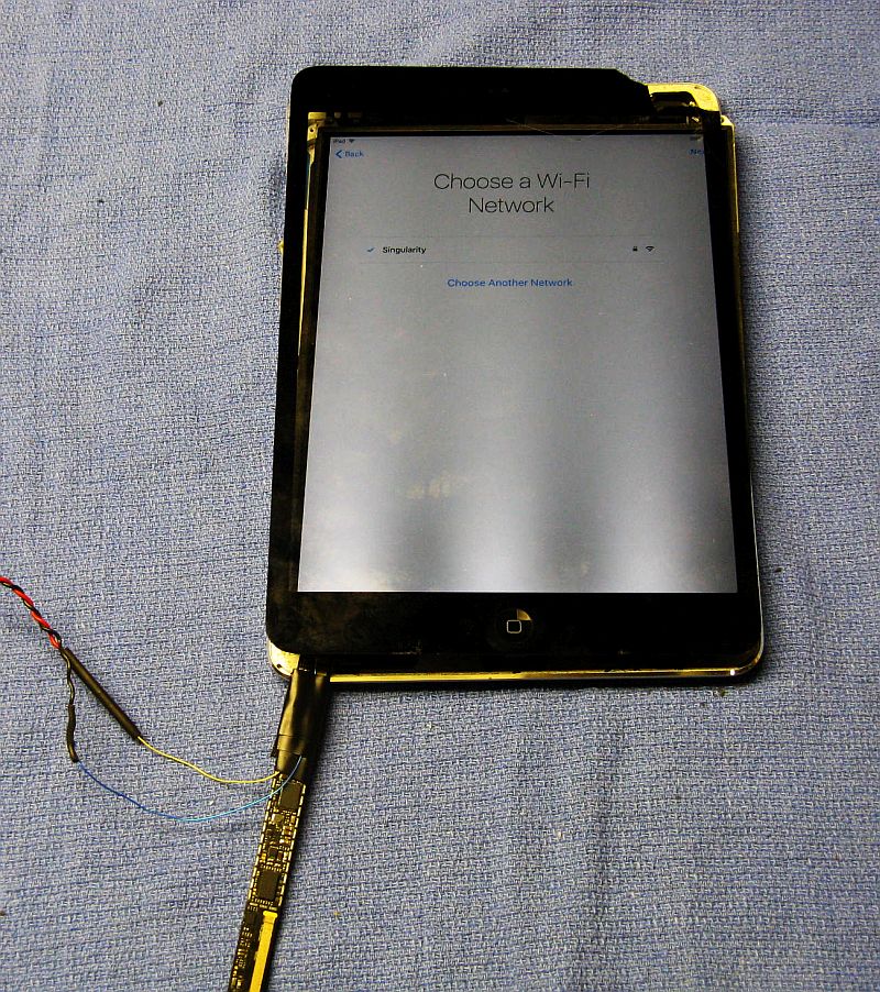
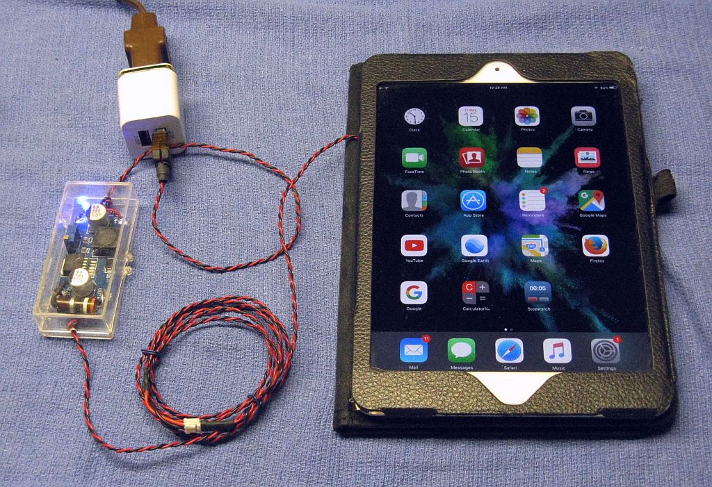
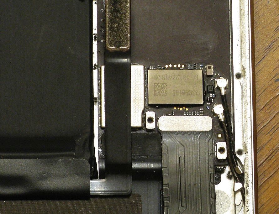
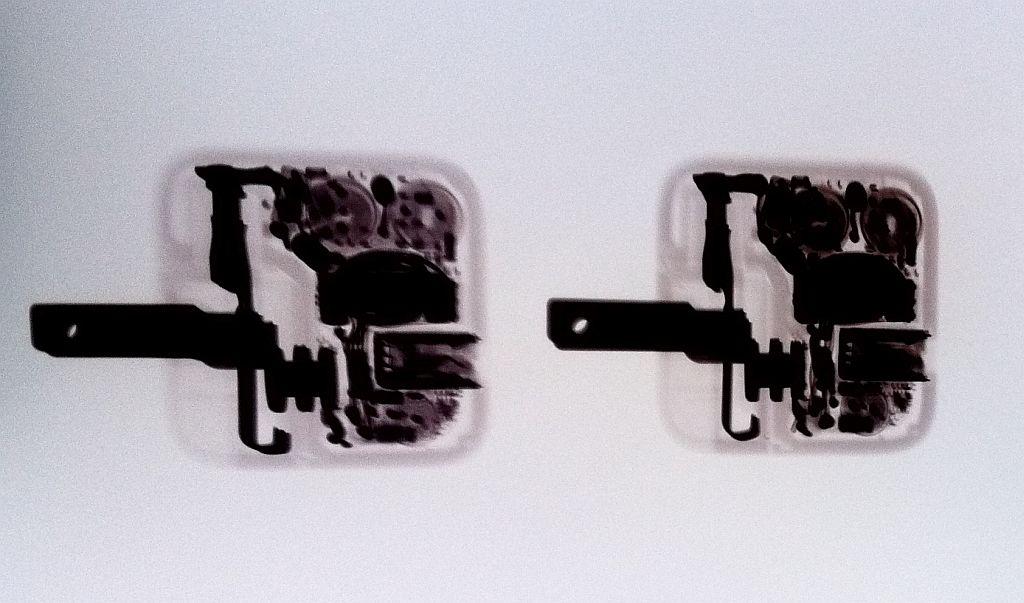
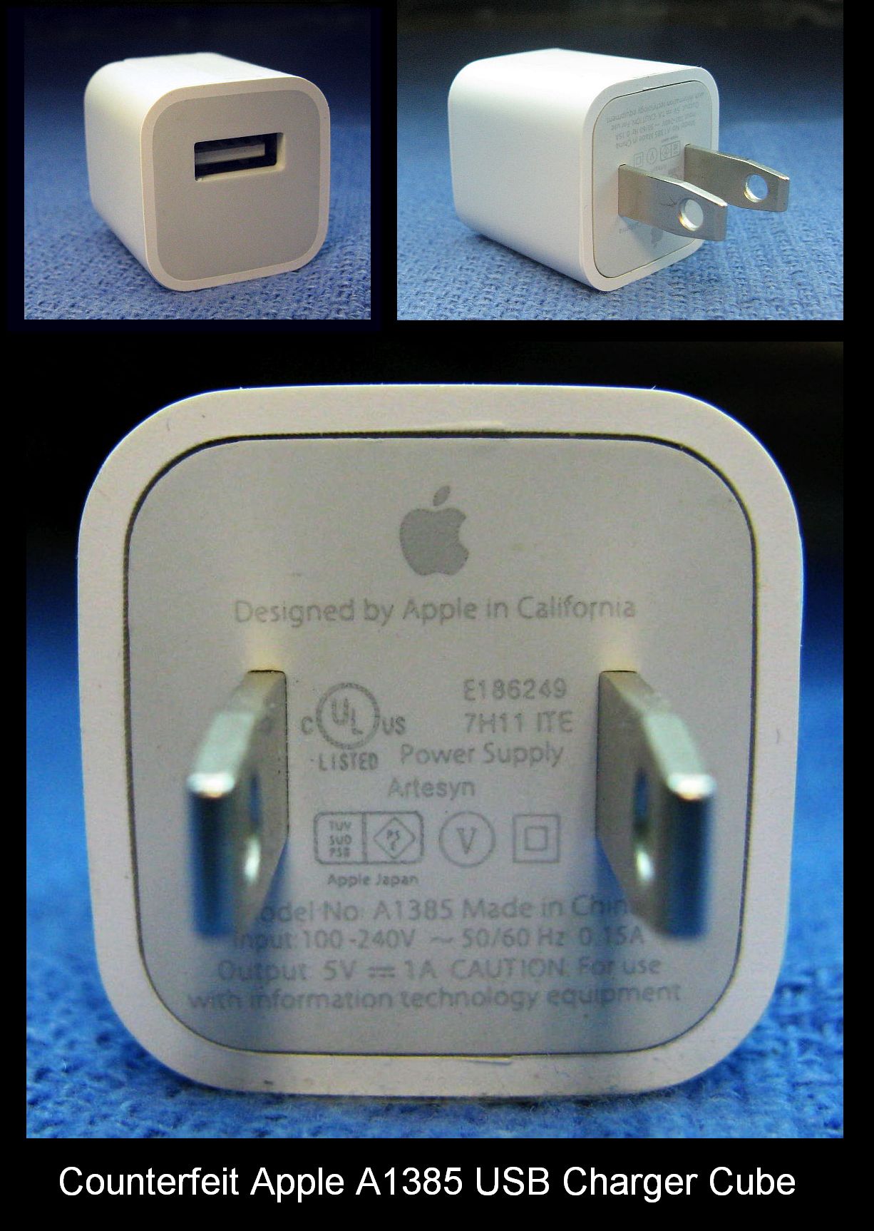
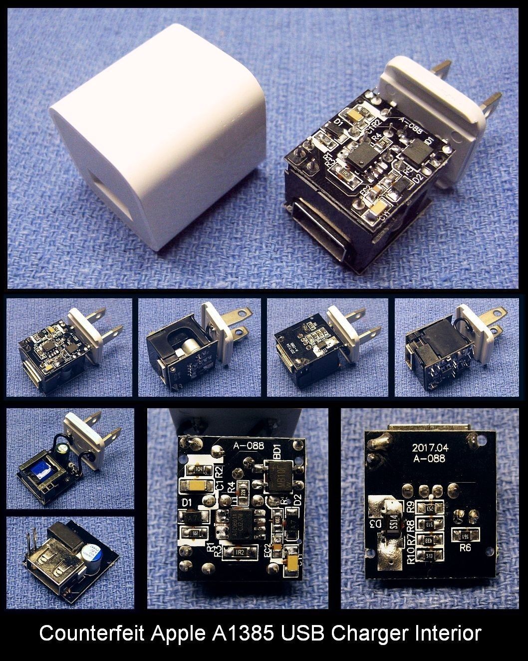
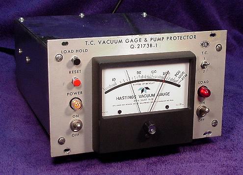