The Test Arm may be a tool in a CNC milling machine, a stage in a semiconductor wafer stepper), a voice coil positioner in a hard drive servo writer, or any number of other precision devices. A single laser can be used with many independent measurement axes through the use of beamsplitters, separate optical receivers, and associated digital processing channels.
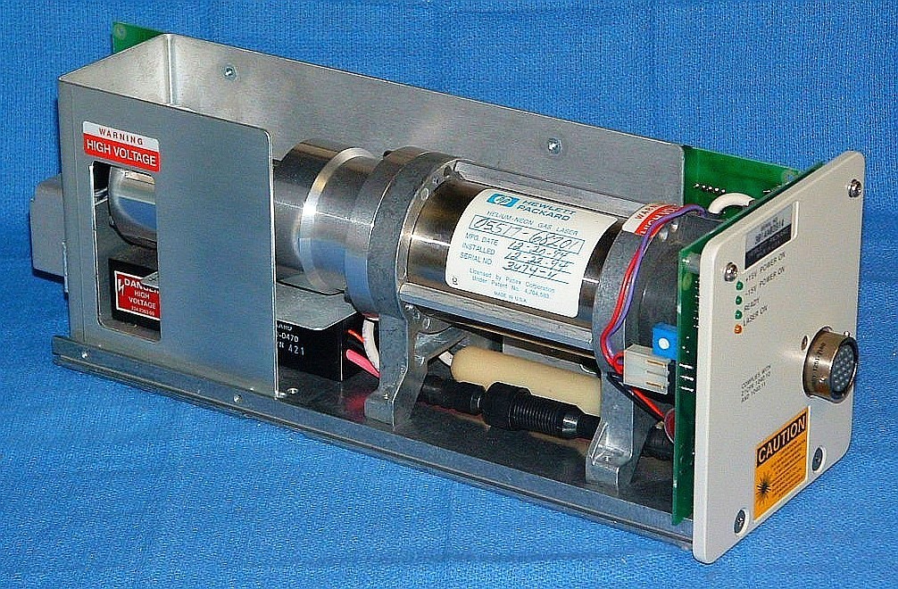
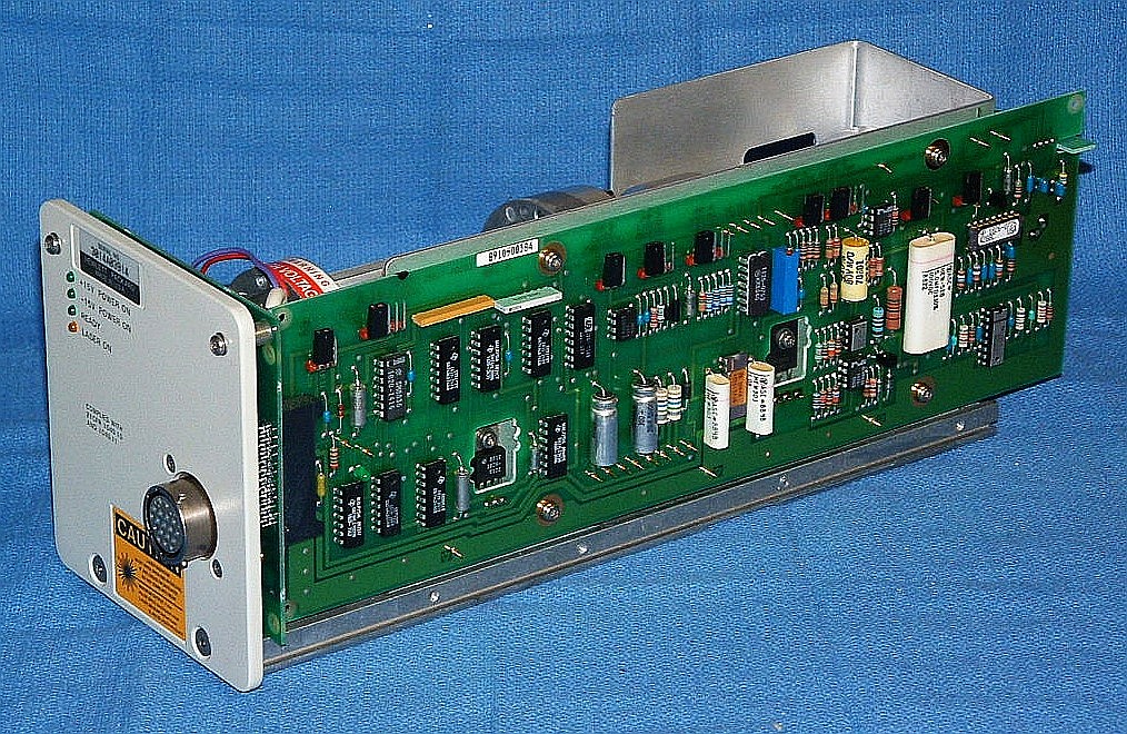
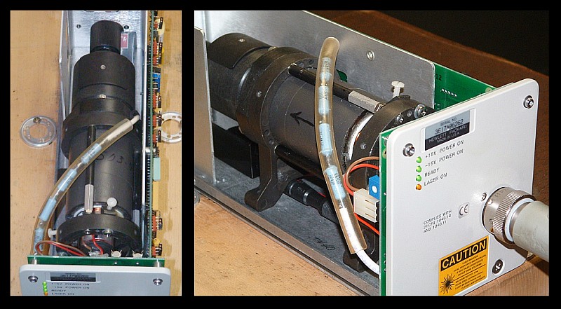
The key attributes that make these lasers ideal for metrology applications is that they produce two frequency components a few MHz apart that are linearly polarized, orthogonal, and oriented along the X and Y axes (horizontal and vertical) relative to the laser baseplate. The optical frequencies are highly stable and the corresponding wavelength (the actual "yard stick) thus should be as well. And, they remain stable for the life of the laser without any maintenance. A 5517B laser with its covers removed is shown below:
The heart of HP/Agilent two-frequency lasers is the custom HeNe laser tube assembly, which represents most of the cost of the laser. When the heart degrades to the point of making the laser unusable or dead, the choices are a heart transplant, or a rebuild. The transplant is simple, quick, and low risk: Find a good tube assembly in a laser that is broken for some other reason and pop it into a chassis with good electronics. Only one trivial adjustment is required.
Used HP/Agilent metrology lasers are also widely available. But many of them are already unusable due to low output power or other problems. These lasers are often run 24/7 from the day they are installed until the day they die or fail preventive maintenence checks. Such lasers invariably find their way to eBay and unscrupulous sellers will either claim the "came from a working environment" or an inability to test. The working environment claim may not be inaccurate, it's just that the laser is dead! :) However, if the seller has tested the laser and offers a warranty, then a previously owned unit may be perfectly acceptable with low risk. Even where it has failed for other reasons like a bad HeNe laser power supply, a broken laser with a good tube may be easily repaired.
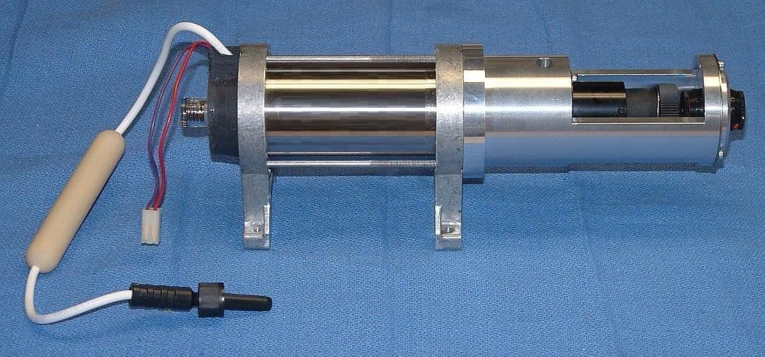
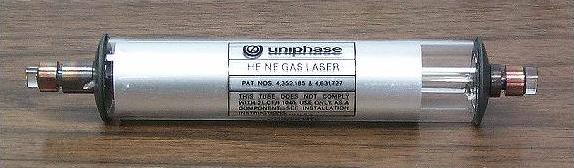
However, where the tube is bad, if it were possible to rebuild it, then this opens up a third possibility with performance potentially equal to that of a new laser at a fraction of the cost. A photo of a typical tube assembly removed from an HP laser is shown below:
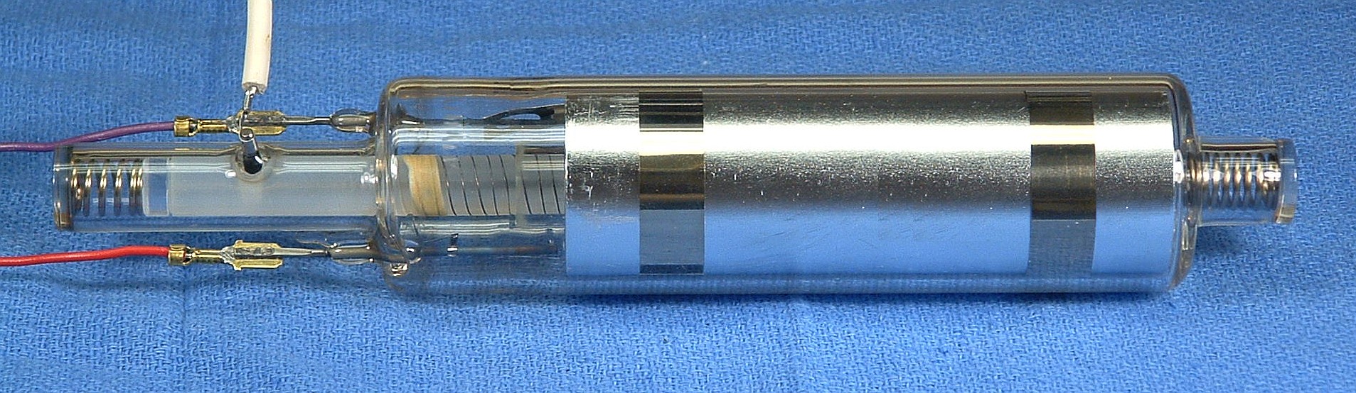
And a diagram of the internal structure of a typical tube assembly is shown below:
The HP/Agilent tube assembly consists of the actual glass HeNe laser tube, a permanent magnet, beam expander, and adjustable waveplates. The part that goes bad is the HeNe laser tube, which is mounted within the magnet using a rubbery potting compound.
Rebuilding an HP/Agilent tube assembly can take two forms:
This glass laser tube is normally not considered a separate replaceable component, only the complete magnet/optics assembly (with the tube) at nearly the price of a new laser.
The benefit of this approach is that most of the vital original parameters of the special HeNe laser tube are preserved, especially if it is replaced in the same magnet/optics assembly at the same orientation so that no adjustments of the waveplates are required. Thus, the beam diameter and divergence, and the stability of the internal heater should be unchanged. However, without knowing the original isotope ratio and gas fill pressure, there could still be differences in optical frequency, split (Zeeman) frequency, and other parameters.
Both of these have a dramatic impact on optical frequency of the center of the neon gain curve. And either of them (though especially the isotope mix) could affect the effective width of the neon gain curve, and this could impact the mode pulling that gives rise to the Zeeman split of the central longitudinal mode, and thus the REF frequency.
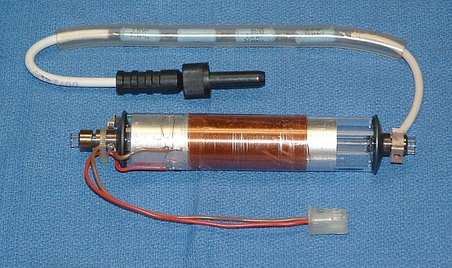
A typical conventional 6 inch HeNe laser tube is shown below:
Then, a heater with characteristics similar to those of the original tube must be installed on the exterior of the tube:
For a more detailed description of doing this, see Installing a Common HeNe Laser Tube in an HP 5517 or 5501B.
The tube above was actually mounted in the magnet assembly from an HP-5501A laser (because that was available) and installed in a 5517D laser chassis. It locked and produced a usable output, though at a REF frequency of only 1.2 MHz. Normally, a 5501A would be between 1.5 and 2 MHz, but due to the use of the standard tube and/or incomplete coverage of the bore by the magnetic field, the REF frequency was lower.
The benefit of using a conventional HeNe laser tube is that it doesn't involve anything that is totally custom or require high vacuum equipment, ultra pure gases, glass working, and other sophisticated processing by the laser rebuilder. When done on a small quantity basis, thes can require substantial investment in high tech equipment and the skills to go with it. However, the laser tube supplier will almost certainly need to modify their "recipe" in terms of gas-fill (He:Ne ratio and pressure) and mirror parameters (reflectance and radius of curvature) at the very lesat. Nonetheless, that should be much less expensive than developing the capability to rebuild tubes in-house, and a company that produces HeNe laser tubes routinely, will have the experience to get the processing correct.
But many parameters of the laser can change, and some of these may impact measurement performance and lifetime. Two key issues with a laser like this that I have tested are the beam profile and jitter or "fuzz" in the MEAS signal, traced to the existence of "rogue" longitudinal modes in the laser output.
The near field beam profile of a laser rebuilt using a conventional HeNe laser tube was found to be noticeably different than that of an original HP/Agilent laser with the 9 mm beam diameter option. There is a distinct hot spot in the center, very obvious by eye. While it should be possible to make this laser work in its intended application when new, it may be more sensitive to changes in interferometer alignment or may degrade more rapidly compared to the normal 9 mm beam profile. The profile looks more like a 6 mm beam where the edges are not cut off, as is normally the case with the HP/Agilent optics, rather than a true 9 mm beam where a higher power diverging lens is substituted in the beam expander and the center portion is enlarged by 50 percent. So, this may just be a 6 mm beam expander with a larger output aperture. Thus, the behavior will be somewhere between that of the normal 6 mm and 9 mm optics.
The basic setup used to evaluate HP/Agilent lasers is shown below:
Any HP/Agilent 5501A/B or 5517A/B/C/D/E/F/G laser can be very quickly evaluated for basic functionality. The oscilloscope display was what initially called attention to the rogue mode issue.
The effect of rogue modes that aren't aligned with the X or Y azes will be interference or baseband fringes that will result in low frequency level shifts of the signal in the optical receiver as the tool or stage is moved. Essentially the same thing will happen if the normal Zeeman (F1 and F2) modes are not pure or are not aligned with the X and Y axes. (Or the entire laser isn't aligned with its baseplate parallel to the X or Y axis.) This may cause small transient errors in position while the tool or stage is in motion. However, the end-points may be accurate if the DC level shift resulting from the periodice static errors is ignored by the AC-coupled optical receiver circuitry, possibly more likely with the newer high performance Agilent optical receivers like the E1708A and E1709A.
The MEAS signal may become fuzzy from duty cycle variations but only when the position is changing. It will appear normal when everything is stationary. While the exact effect on accuracy is not known, theory suggests that there could be errors of up to 10s of nanometers while the tool or stage is in motion, but no error at the end-points if the condition, above, is satisfied, though the settling time may be larger. However, there could be ripples in the velocity (or any other) function that needs to be feedback controlled between end-points.
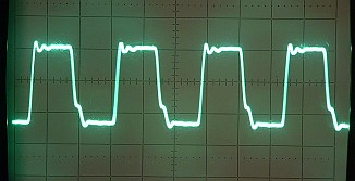
The symptoms are as follows: The MEAS signal out of the optical receiver should be a clean square-wave with approximately a 50 percent duty cycle. As the remote mirror or cube corner moves, the period/frequency of the square-wave gets smaller or larger due to Doppler shift but the duty cycle remains the same. The system determines position by accumulating the relative phase difference between MEAS and REF, which is a square-wave of fixed frequency, the unmodified Zeeman beat output of the laser
These two photos show an example of a normal MEAS signal with clean rising
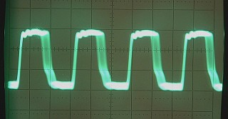
and falling edges, and a MEAS signal where there is a small amount of movement
of the remote mirror. In fact, it's likely that both the rising and falling
edges are moving back and forth, but since the oscilloscope only triggers on
the rising edge, that one appears sharp. (The jaggedness in the falling
edge is an artifact of the wiring termination.)
The photos below made using a Scanning Fabry-Perot Interferometer (SFPI) show the longitudinal modes of a normal 5517 laser on the left with those of a 5517 laser rebuilt using a conventional HeNe laser tube that had rogue modes on the right:
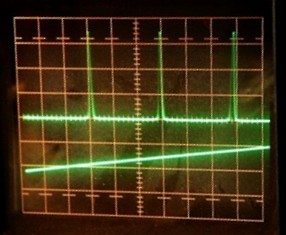
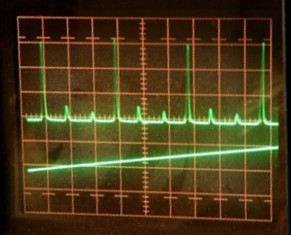
The large peaks consist of both F1 and F2, but the SFPI: is unable to resolve the difference in frequency of only a few MHz. These are the normal split longitudinal mode of the Zeeman laser. As can be seen, there is no evidence of any other modes in the left photo display of the normal 5517 laser. The display of the laser on the right with the rogue modes has a pair of smaller peaks on either side of the main peak. I believe that the spacing of the rogue modes with respect to the F1/F2 modes are approximately +/-1.3 GHz corresponding to a laser tube cavity length of about 11.3 cm or 4.4 inches.
The diagrams below show why rogue modes can be present. If the tube is too long and its FSR is thus small enough, an adjacent longitudinal mode on each split neon gain curve may be above threshold and thus oscillate. One will be approximately 1 FSR above and the 1 FSR below the Zeeman modes. (The distance is approximate due to mode pulling effects.)
By rotating a polarizer in front of the laser while observing the SFPI display, it was possible to determine the orientation of the rogue modes. They were at approximately a 30 degree angle with respect to X and Y. At this point, such a result was expected (actually hoped for since it was the only explanation that made sense!) but still surprising, as all the longitudinal modes of a laser tube are normally oriented along a single axis, or orthogonal to it, and these were off by 30 degrees. However, it's possible that a combination of the use of the Zeeman magnet, the entire bore not being inside the magnetic field, and the waveplates, could account for this.
The reason that the rogue modes at 30 degrees cause signal degradation is that some portion of each rogue mode passes through both the reference arm and measurement arm of the interferometer, and thus they interfere with themselves at the optical receiver, resulting in the baseband fringes. These change the level of the signal envelope, and confuse the receiver electronics, essentially by shifting the threshold that is used to convert to the optical receiver's digital output. This effect is similar to that of misaligned or impure normal (F1/F2) modes.
However, the signal jitter using a 10780A or 10780C optical receiver is probably a worst case. The higher performance E1708A or E109A may be less susceptible to signal envelope level fluctuations.
Note that even if rogue modes are present, if they are aligned with the X and Y axes, the only effect will be to slightly decrease the signal level relative to output power. It's possible that careful adjustment of the waveplates could eliminate the effects of the rogue modes by aligning them with the X and Y axes. It's also possible that rogue modes could exist in genuine HP/Agilent lasers but go undetected if aligned in this way. Testing with an SFPI is not something that would be done routinely.
The good news is that since the two rogue modes are already low level, they may actually disappear after the laser is used awhile and the overall gain (and output power) decreases!
Where a new conventional (but possibly modified) HeNe laser tube has been installed, the lifetime will depend on its construction and quality. Typical commercial HeNe laser tubes have an expected life of 10,000 to 20,000 hours with some going to 40,000 hours. But since a very small tube must be used in the the HP/Agilent lasers (due both to space limitations and the required longitudinal mode structure), the life could be much shorter. The cathode area is small and the gas reservoir is small. Such tubes may have a life of only 5,000 hours, though there are exceptions - Small Zygo tubes last 20,000 hours.
A rebuilt laser using a conventional HeNe laser tube required about 7 minutes before the READY LED started flashing, and over 9 minutes for the READY LED to come on solid. It just barely got in under the deadline.
So, a rebuilt laser should be checked to make sure the REF frequency is acceptable, either based on the model and options of the original laser, or based on those of the machine in which it is to be installed. A higher REF frequency translates into a higher maximum velocity capability for the measurement system, so a rebuilt laser with a higher REF frequency should be acceptable if the data processing electronics can handle it without producing measurement errors, or aborting due to detecting that it is out of range. But the expected increase in REF frequency due to aging should be factored into the determination of whether it will continue to work correctly later. A rebuilt laser with a short useful life will be no bargain. However, if the REF frequency is below the spec'd minimum, performance may suffer.
A rebuilt laser using a conventional HeNe laser tube was tested to be about 75 MHz above a healthy HP/Agilent laser. This is still only about 0.15 ppm difference.
The test setup is shown below:
A rebuilt laser using a conventional HeNe laser tube had a frequency variation over 8 hours of less than +/-2 MHz, and this is very conservative. It could be much less.
Even the laser with the beam profile and rogue mode issues could probably be made to work in perhaps all but the most critical applications. However, there have been reports of an inability to follow the manufacturers alignment procedure due to some aspect of this laser, so this would need to be modified. And there would be some risk, so rigorous adherence to a weekly or monthly test and calibration regiment would be essential in identifying and tracking any changes in performance over time.
These same issues could occur with other Zeeman lasers such as those from Excel, which manufactures several models that are similar to those from HP/Agilent. However, metrology lasers from Zygo are based on different technology and already use HeNe laser tubes of conventional design, though built by or for Zygo. There would still be some areas that could change, but these would be limited to slight changes in beam profile, and a likely shorter life.