For contact info, please see the Sci.Electronics.Repair FAQ Email Links Page.
Copyright © 1994-2022
Reproduction of this document in whole or in part is permitted if both of the
following conditions are satisfied:
1.This notice is included in its entirety at the beginning.
X-Rays are what are known as "ionizing radiation" and is acts in a
fundamentally more dangerous way than radio waves, light, and microwaves.
Its much higher energy photons have the ability to damage biological tissue
including cells and the DNA contained therein. This can result in
mutations leading to cancer and other things that we won't go into here.
ANY unnecessary exposure to X-Rays is to be avoided so should anyone reading
acquire or gain access to an operational X-Ray system, measures must be
put into place to prevent exposure. Lead shielding would probably be the
most desirable approach since common building materials may NOT block
X-Rays unless excessively thick. Thus simply being in an inclosed space is
no guarantee that someone in the next room won't have some exposure.
That's why they put a lead apron on you when having dental X-Ray.
But there's much more to X-Ray safety than simply using a lead box. So,
if you're serious about actually running a scrounged X-Ray machine - or
even one that you built using a high voltage rectifier vacuum tube - make
sure you understand and follow the much more complete safety guidelines
readily found elsewhere.
If servicing or otherwise dealing with a piece of X-Ray equipment where
the electrical connections to the X-Ray tube need to be removed, realize
that almost any type of X-Ray equipment is has the potential to be absolutely
and totally instantly lethal from electrocution! X-Ray tube power is
typically 50 to 150 kV at 10s to 100s of mA. Even a lowly dental intra-oral
X-Ray unit uses 70 kV at 10 mA, but significant energy may be available in
charged capacitors. An X-Ray machine used in general radiology might
use 150 kV at 200 mA! That's 30 kW!
(From: Terry Greene.)
If an X-Ray power supply is fired unloaded, output voltage can exceed a
quarter of a million volts, and can hold an
incredible charge long after the power is disconnected and can easily
kill. I've startled people down the hall by shorting the generator secondaries
on a disconnected machine that was fired (malfunction) unloaded. An impressive
discharge. NEVER work on an x-ray supply without shorting the output first. If
it doesn't kill you, you won't forget it... assuming you ever remember it. :-)
There is no practical problem with x-radiation at the typical voltage used in
most gas type lasers. All mammography tubes use special beryllium windows for
the radiation output because x-radiation at those low energies (20 to 32 kVp)
won't penetrate the glass envelope of a standard tube. I've tried it. A glass
envelope (standard) x-ray tube won't produce any exposure at all at 15 kVp
according to my test equipment. (Keithly ion chamber) Even with complete
evacuation, I seriously doubt you could find measurable x-radiation output from
a glass bore laser.
(From: Terry Greene.)
Dental X-Ray usually has fixed kVp in the 65 to 90 kVp range. The vast
majority of them are set up at 70 kVp, usually at about 10 ma.
As far as small medical, hmmm... define small. General medical stuff is usually
adjustable in the 50 to 125 kVp range for single phase or 50 to 150 kVp for
three-phase. These machines usually have adjustable mA from 25 to as much as
1000 mA. Smaller units as found in the offices of general practitioners will
typically be adjustable from 50 to 300 ma.
A few of the many exceptions to the above:
Operating at either 20 kHz or 100 kHz, these unit have RMS output that
exceeds three phase output by a few percent.
I enjoy reading discussions that add to our knowledge but I
immediately became suspicious of the dose values reported by the two
previous gentlemen.
After some quick research to confirm the values I had in mind,
here's what I found:
(From: Gregory W. Froehlich.)
In 1981, the mean exposure for bite-wing dental films was 334 mR. It's
certainly less now, so 70 mR doesn't seem too surprising (in 1980, a
chest film was about 30 mR, and a mammogram about 500 mR).
The stuff I've seen for total average annual radiation is about 300 mR.
Background radiation (environment and from people's own bodies)
accounts for about 80% of that. Radon, on average, makes up about 55%
of the total. Now, if you live in parts of New England (high radon,
from the granite I think), the background radiation is 2.5 times as
high; if you live in Leadville Colorado (lots of cosmic rays and metal
ores), the background level is 3 times as high. Don't know about the
exposure per hour of sun exposure; it's probably less than that of
sitting inside, since radon levels are higher indoors and the main
problem with sun is UV, not ionizing radiation (X or gamma). Anybody
know the exposure rate for flying at 33,000'? I'd bet a coast-to-coast
trip comes with 100 mR or more, from cosmic rays.
X-Rays don't spatter, but they do scatter. Some x-rays are partially
absorbed by the patient's body and are scattered. This normally would
cause image unsharpness, but most modern systems also employ a focused
grid under the patient to filter out scattered rays and only allow
direct x-rays to pass. Incidentally, these scattered x-rays are what
cause the occupational exposures to x-ray personnel, however their
intensity is usually less than 1% of the primary beam intensity at 1
meter from the central beam axis.
One last important factor in x-ray imaging science is the X-Ray tube's
focal spot dimensions. A smaller focal spot will give a sharper
resultant image. Normal modern x-ray machines usually have two focal
spots which range between 0.8mm and 2.0 mm. In mammography, where
image sharpness is particularly important, standard focal spot sizes
are 0.1 mm and 0.3 mm.
The next step, which is occurring now, will be the replacement of film
entirely with digital imaging receptors. This will further lower
patient dose, minimize retakes, and give added imaging quality as the
technology advances into the future.
For more about X-Ray imaging physics, I would recommend "Physics of Radiology"
by Anthony B. Wolbarst, 1993, Simon & Schuster.
In rare cases film is used isolated (for example in retro-alveolar
examination). Generally they are used together with fluorescent screens
("enhancing screens" or "phosphor screen"). The darkness (optical
density) of the developed picture, is reflecting the sensitivity of
overall system: film+fluorescent screen so, it is useless to speak
separately about the "sensitivity of the new films". One of the most
known supplier is KODAK. They have a lot of little but very clear manuals
about the radiology. Other important suppliers are AGFA, 3M, FUJI,
DUPONT, SIEMENS.
The main parameters of the couple film+enhancing screen are sensitivity
and resolution. The couples are specific to type of examinations because
in some cases is very important to obtain maximum resolution and in other
maximum sensitivity. More sensitive couple means less X-Ray photons sent
to the patient but do not forget the X-Rays energy spectrum.
For essential the X-Rays are giving a little part of the film darkness
but the light from the screens is the major film darkness source. This
light is proportional to the X-Ray absorption by the screen. The absorption
is essentially dependent on the X-Ray energy. If you choose two
different couples and you compare their sensitivities in two situation,
let's say at 80kV and at 15kV, you may find that each one is more
sensitive than the other but at preferred kV.
Let's remember that the CaWO4 was very long time the main ( see only)
phosphor used in radiology. Some products based on it were used as
reference. This phosphor is practically obsolete today but
unfortunately is still used as reference. Unfortunately there are two
implications:
And, about using modern film on old X-Ray machines, basically there is no
restriction. However adjacent problems may arrive:
Replacing the films by TV cameras is well known and under continuing
progress from long time ago. The technology that is relatively new is CCD
based X-Rays sensor. The first step was done by Trophy Radiologie (France)
when the RVG (RadioVisio Graphy) was introduced on the market. RVG is a
CCD based X-Ray sensor to be placed in the mouth rear the teeth just like
the well known intra-oral film. A cable links the sensor through a digital
electronics to a display. The system is used like before, with the
classical films but instead the chemical processing we have instant images
on the display (computer). The first solution proposed for the intra-oral
sensor was for short time because 1992, Regam introduced his X-Rays
intra-oral imaging system named " Sens-a-Ray ". One year later, Gendex
(Italy/USA) introduced the same technology but named " Visual X "One year
late Shick (USA) introduced his sensors and then Siemens(Germany),and
MedizinReichner (Germany). Soredex (Finland) proposed a solution based on
an intermediary support: memory phosphor of Fuji.
A second application in radiology for the CCDs is for the digital
panoramic. In 1995, SIGNET(France) begun the selling of DXIS� . This is
a kind of universal kit being able to upgrade any classical panoramic int
a digital one. Siemens an Trophy followed with fixed configuration for
their last panoramic model. Planmeca(Finland) is also announcing his digital
panoramic. Some specifics merit to be underlined:
Let's return an instant to the sensitivity. When the intra oral sensors
arrived, the commercials claimed: "The CCD based sensor is 4 times more
sensitive than the film!" (But what film?!) When the second arrived,
other commercials said: "Our CCD based sensor is 5 times more sensitive
than film" and so on... Other formulas which are equivalent as
arithmetic but more penetrant were also used "our sensor permits a
75% reduction in radiation!" or "our sensor permits a reduction of 80%
in radiation" and so on... The rough commercial competition paused far
the evaluation of intra-oral sensors. Each manufacturer discovered by pure
hazard articles in the press which praise their product and immediately
displayed it. Conclusion: a high amplitude wave was created sustaining
the the sys that the new CCD based technology permits to reduce many many
times the X-Rays.
As designer of one of these sensors and of the DXIS� system, I am
convinced that the main explanation for the CCD based X-Rays intra-oral
sensor is not by the CCD usage but just by the usage of the phosphor
screen. The commercials forget to explain that they are comparing the
classical very high resolution dental film, which is not coupled with
phosphor screens with a system based on CCD which is receiving the light
from a phosphor screen. Near the same sensitivity may be obtained with a
film coupled to the screens. In the fact they realized an important move
on the market: they convinced the dentists that is better to renounce to
the resolution which is too high and get benefit from the X-Ray economy.
The most important advantage that the digital sensors bring is the
computer environment.
The CCD story risks to be repeated in the competition on panoramics.
(And now, CT scanners for the dental market. --- Sam.)
One difference is in how the HV obtained from line voltage:
A 3 phase 12 pulse system takes the line voltage, puts it through step
up transformer(s), rectifies it, and applies it to the X-Ray tube. Very
simple technology that dates to the early days of commercial X-Ray systems.
A high frequency generator takes the line voltage rectifies and filters to
to make DC. The DC is then chopped at a high frequency and a combination of
transformers and voltage multipliers then steps it up to the required
voltage. Using a high frequency enables many of the components to be
much smaller such as any transformers and capacitors.
High frequency generators are smaller and lighter and lend themselves to
digital control.
High frequency generators are not used exclusively with digital
X-Ray system. It is simply an efficient, light weight means of producing the
high voltage. For example, modern CT scanners almost always use this
technology especially where the HV generator is mounted on the rotating gantry.
(Unless you consider CT to be a subset of digital X-Ray which it is).
There is no technical reason why a high frequency generator cannot be
used with any X-Ray system.
Most newer battery powered portables are 20 khz high frequency machines.
The older ones (G.E. AMX etc..) are generally 500 Hz.
(From: Chris Smolinski.)
I've designed a switching power supply which drives a HV multiplier inside
of an X-Ray source. The X-Ray source contains a 1:26 step-up transformer
and a multiplier to produce up to 80 kV. I need to feed it with a 12 kHz
signal, about 300 V p-p. The design of the x-ray source cannot be changed,
I'm stuck with it.
My power supply uses a push-pull amplifier to produce this 12 kHz signal.
The center tap of the primary of a transformer is connected to a 96V DC
supply, and I PWM the signal to two MOSFETS connected to each side of the
primary. Maximum output power is about 500W.
I've noticed that after a period of operation at higher power levels, the
transformer becomes quite warm [hot, I guess it's kinda relative]. I don't
have exact temperatures handy. Perhaps I'm being too conservative, but I'd
like the transformer to run somewhat cooler. The transformer design was
mostly empirically determined, I'm sure it's far from optimum.
Suggestions on what I can do to improve it? Sources for useful design
hints/information? Unfortunately, they don't seem to teach you anything
about transformer design in EE courses anymore (at least not at U of
Maryland 6 years ago...).
(From: Someone at a major X-ray tube manufacturer.)
I have been a X-Ray Field service engineer for about 45 years. In your x-
ray tube section it was stated that you rarely see a gassy x-ray tube.
Today (2016) in the Medical diagnostic environment, most tube failures
*are* due to gas. This is mainly due to use of high kVp techniques. Because
of the use of rare earth screens or digital detectors (requiring lower
dose), the anode heating is a lot less and we don't see many cracked
anodes.
The gassing occurs because the target is a casted alloy of tungsten and
molybdenum. When it is cast, gasses are trapped within the casting.
One of the steps in the manufacturing process of the X-ray
tube is when the glass envelope is being evacuated, the target is
heated to a higher temperature than what it would experience in
normal use. This heating process releases much of the gas that
was trapped in the anode. However, during normal use the anode
goes through many heating cycles. Due to the expansion and contraction,
more gas is released. Tube arcing will be first seen of course at the
higher kVp's. In the early days radiologists wanted high contrast images.
Nowadays they like images with a long latitude, grayer image, particularly
on chests because they can see anatomy behind the heart and sternum that
otherwise would be blocked in a high contrast technique, low kVp, high
mA. So in conclusion the reason we see more tube arcing due to
gassing is due to the higher kVp techniques in use today.
The X-Ray tube (or if this link should die, my copy at:
Sam's Copy of The X-Ray Tube) is a nice
introduction that makes some of the following seem a bit lame by comparison,
but mine are actual X-Ray tube guts. :)
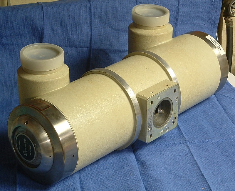
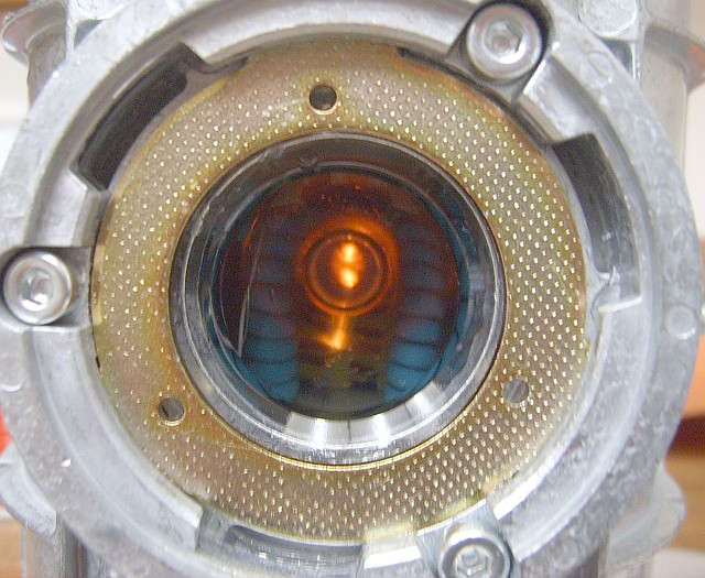
A typical X-Ray head or housing is shown in
Bennett X-Ray Machine Head Assembly.
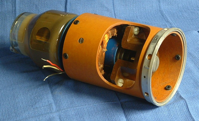
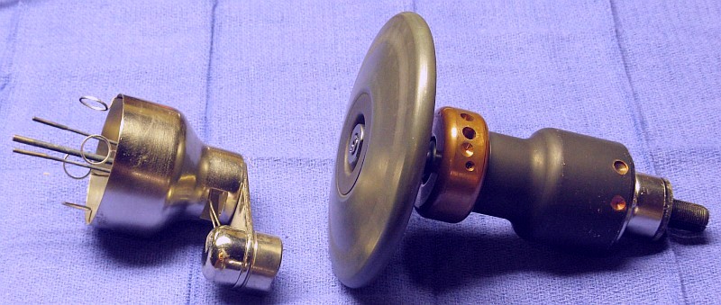
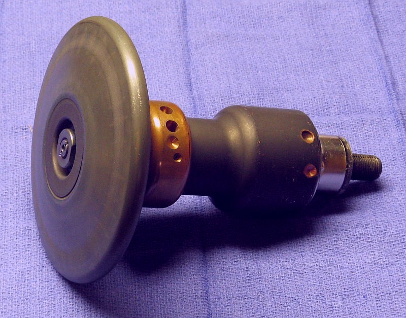
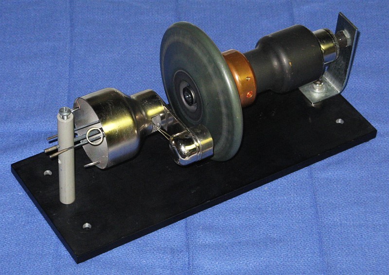
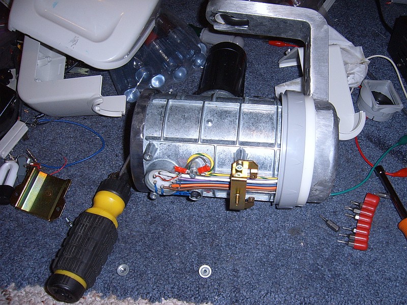
An X-Ray tube and motor stator similar to the one inside
this head is shown in GE X-Ray Tube
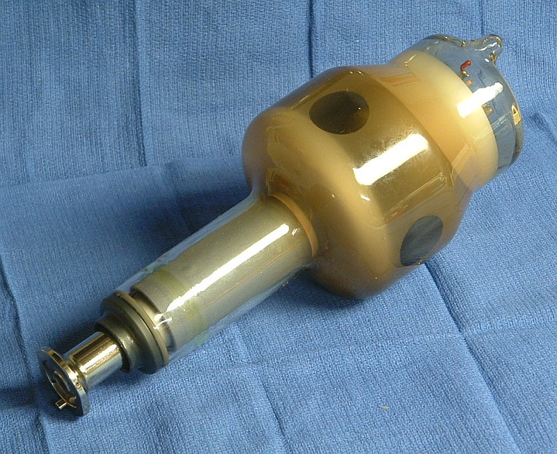
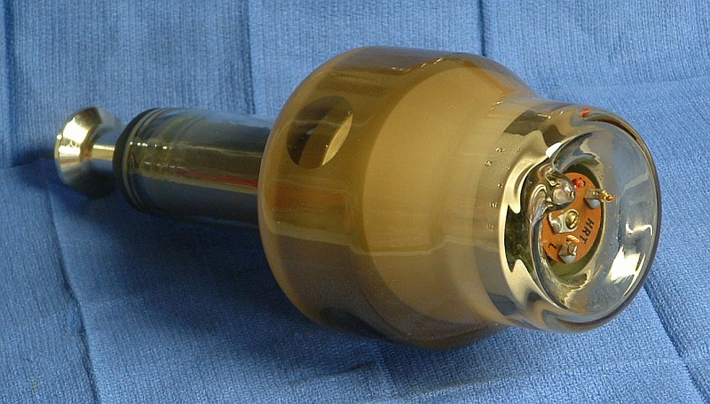
and Motor Assembly and removed in
Typical GE X-Ray Tube (Insert) - View 1 and
Typical GE X-Ray Tube (Insert) - View 2.
(The X-Ray head was made by Eureka.)
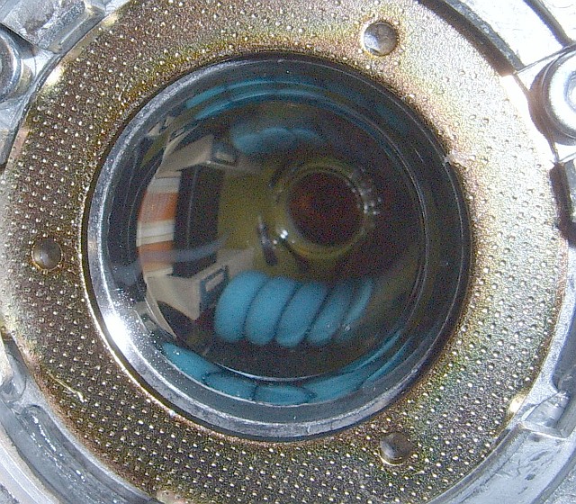
A part of the anode can be seen through the circular window in the
last photo. Although not readily visible, I was told that the rotor controller
failed and the fail safe circuit didn't catch it. Multiple spots were melted
on the anode resulting in an instant "Gassed" tube which started arcing.
Here are some photos of a rather large X-Ray tube with a 5 inch diameter anode
(close to CT-class) that didn't survive shipping:
The CGR tube was originally generally similar in appearance to the GE tube,
above, but larger.
Shipping X-Ray tubes that aren't properly mounted inside an X-Ray head or
housing is extremely difficult given the heavy anode/rotor assembly (this
one weighs over 3-1/2 pounds) inside the fragile glass envelope. See the
section: Shipping X-Ray Tubes (Inserts).
This tube was inadequately packed but might not have
survived even in a 30x30x30 inch box filled with foam.
Although claimed to be new, it appears as though this tube has seen at
least some service. The "track" where the electron beam hits is very
slightly more textured than the rest of the anode but shows no evidence
of the type of major damage that would result if it failed to reach adequate
speed during an exposure. But there are a dozen or so very slight blemishes
roughly the size of the filament (unfocused) which might have been caused
by some type of events. Several of these are visible in the photo.
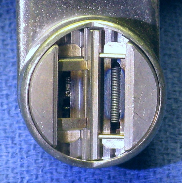
The larger filament - which essentially is imaged onto the anode - is
1 cm in length. There is no focusing electrode as
with a CRT but the structure that the filaments are mounted in
perform some electrostatic focusing. However,
much of the reduction in spot size in the radial direction
comes about as a result of the steep angle from which the
X-Rays that are finally used are emitted off the surface
of the anode. That center of the beam is at a right angle
to the tube axis with the unwanted part cut off by an aperture, but
the anode is slanted at a typical angle of only 12 degrees, so
that 1 cm (for the larger filament) is reduced by a factor of 10.
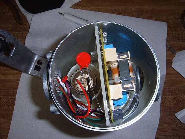
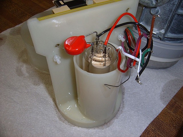
(Mostly from: James Sweet.)
Here are some photos of the head components:
Notes:
The transformer is definitely custom made for this specific system.
The only info I have is what I was able to extrapolate by visual
inspection and driving it with a low voltage while measuring the output.
I successfully tested the head using a MOSFET half bridge fed by an oscillator
that was adjusted to about 80 kHz while watching the current waveform. The
input voltage was adjusted with a Variac feeding a voltage doubler to get
approximately 290 VDC. Both the frequency and voltage have to be regulated
to keep everything happy as the tube current varies depending on heater
voltage. Closed-loop feedback is mandatory since there is a lot of sag
in the multiplier ladder. I just used a DMM for playing around with it
but the original driver board used the feedback directly to control the
regulator.
CAUTION: If powering the head using a home-built driver, note the duty
cycle (cooling requirements) in the manual! This head is not designed for
continuous operation. Something like 0.1 second on every few seconds max,
dependent on tube current.
Anyway, call to all hospitals and companies that sell/overhaul
x-ray equipment and ask for old ones. If you have a realistic need
for one, you might get one. Talk to the engineers etc., not the
bureaucrats. Remember to emphasize that you need it as voltage source,
NOT for producing x-rays (which requires permits etc.). If that
doesn't work, ask what junk yards they sell the old ones to, and
contact the junk yards and offer reasonable amount of money for
one, so the junkyard will save one for you and call you to pick
it up. The value of them for junk yards is the junk value of
copper (about 2-4 usd/kg) in coils, the iron and transformer oil
is practically worthless to them.
It is usually a good idea to get to know your local junk yards.
After you have been acquiring strange pieces of equipment from
them for a while they will call you when interesting things
arrive. :)
I have so far found a mass spectrometer, a spectrophotometer, two SEMs,
various high-vacuum pumps, x-ray transformers and tubes,
HV-transformers etc., etc., from junk yards. They are a real gold mine
for people who know what the junk is. It is absolutely amazing
what research institutes, hospitals and universities throw away.
(From: Sam.)
Keep in mind that aside from the radiation and electrical DANGERS,
most of this equipment is BIG and HEAVY, may require special power,
and is likely messy to service. Think carefully before obtaining
what may end up being a refrigerator-size boat anchor!
(From: Terry Greene.)
There are two filaments, one small focal spot and one large. One
connection is the common. The typical voltage varies
around 6 volts at 3 to 5 A. At 4 A most tubes will run
around 100 mA at 50 kV. All modern tubes have similar ratings. In the
display I built, I used a 6.3 VRMS, 6 A transformer as that's what I had
laying around. It worked just fine on the large filament but might blow the
small one at that voltage though. The filaments are designed to control the
current by temperature and generally run at a bright orange in
operation. If it starts getting too close to white, it's too hot and you
risk smoking it. For a non-X-Ray producing display, the voltage/current
won't be critical, but I wouldn't let it go much over 5 amps to keep
from toasting the filament. I know the Eureka has a max
filament current listed of 5.2 amps. for each of the filaments with
normal filament voltage (at max current) listed at 7.8 to 10.6 for the
large, and 5.9 to 8.1 for the small. The GE won't be far from that.
The motor in common 600 mA and lower systems spins at around 3,600 rpm.
Many of the high power systems have a high frequency rotor drive
circuits that will spin the rotor at 10,800 rpm. G.E. high speed rotor
controllers are known as a RARC (Rapid Acceleration Rotor Controller)
and SARC (Super Acceleration Rotor Controller). GE just loves acronyms.
Any tube rotor will work fine on 60 Hz. High speed 180 Hz. operation
just raises the power handling capability a bit.
There are no standard color codes. A DVM will tell you all you need to know.
Two windings. One connection is a common. One connection is a main
winding at around 20 ohms. One connection is a phase shift at at around
50 ohms. If you check across the outside leads you will see around 70
ohms. Those are average numbers and the exact numbers may vary
significantly from model to model, but the ratio will stay reasonably
consistent. Some are as high as 30/90 with 120 total, some as low as
15/35 with 50 total. The common is hooked to line common, the main hooks
to hot and the phase shift needs a motor capacitor in the line and hooks
to hot as well. Around 30uF works well. The value is not critical. I've
seen systems with 15uF. Medical X-Ray systems usually start the rotor
by applying 220VAC to spin the rotor up rapidly. After about 1.5 seconds
the voltage is reduced to around 50VAC. Some of the inexpensive vet.
units simply bring the rotor up on 120VAC and leave it at that. The
acceleration is slightly slower, but it's barely noticeable. The vet.
units that do so usually have a 2 sec delay before exposure is allowed
instead of a 1.5 sec delay. All modern tube rotors will run at 120VAC
all day without damage. For my display I simply used 120VAC.
Apparently, the first (known) radiograph was taken 6 years before
Roentgen discovery. The story goes like this:
On February 22 1890, Professor Arthur Goodspeed at the University of
Pennsylvania was demonstrating the Crookes cathode ray tube to a photographer
named William Jennings. Next to the tube Jennings had placed a couple
photographic plates upon which he had tossed some trolley tokens. When
Jennings later developed the plates they were fogged and two dark round disks
appeared on the plate plus some static marks. It wasn't until after Roentgen
discovery was published that the two men realized what had occurred.
(From: Sam.)
I don't know whether this story is totally accurate. One question I would ask
is: "What prompted Professor Goodspeed to develop plates that to the best of
his knowledge had not been exposed?". :)
My latest dilemma concerns, as the title of this post would suggest,
the issue of potting for security and the x-raying of said pot for the
purpose of breaching that security.
My question may be out of the realm of electronic design, but since
there seem to be many *know it alls* (~: that frequent this newsgroup,
I thought I'd give it a shot here in SED.
Question is,,,,,, Would a copper clad circuit board, un-etched, and
coated with solder, be sufficient to block the x-rays from an x-ray
machine and foil the intentions of someone trying to hack the circuit by
means of x-raying ?
(From: Bill sloman.)
It depends on what you are trying to conceal and from whom. X-Ray
absorption depends on atomic number. Carbon has an atomic number
of 6, silicon 14, copper 29, tin 50, and lead 82, so the lead in
the solder will dominate the picture. Wrapping the circuit in lead
foil would probably be better, and loading the potting mix with lead
shot of a variety of sizes would be even better.
Any one of these would probably stop someone trying to get a shadow
image of the circuit with a simple medical X-Ray machine, and would
probably cut down the transmission through the potted sample enough
so that a brain scanner wouldn't get very far.
Somebody with the resources to lash-up a high voltage X-Ray source
to a precision stage could probably improvise an effective
tomographic set-up, and someone with access to neutron radiography
might be able to see through the lead, but it would probably be
easier to organize a break-in at your plant to steal your drawings.
(From: Sam.)
While potted electronics may appear to be impregnable, the liberal application
of heat and pointy tools is often sufficient to pry loose their secrets.
I know someone who routinely repairs various types of high voltage modules
using only thermal and mechanical means of disassembly, and restores them
to full operation and near-new physical appearance. And he has totally
reverse engineered some of them in the process. He has also X-rayed many
of these using a dental X-ray head
with sufficient clarity and resolution to enable someone with
a basic knowledge of their circuitry to be able to determine virtually
everything but the actual component values and part numbers. ;-)
See the various examples in Sam's Laser FAQ chapter:
Complete HeNe Laser Power Supply Schematics.]
(Just search for "X-ray".) A simple X-ray examination could at least
be made more difficult by including an insulated sheet of lead just behind
the circuit board. But, the entire idea of concealment from X-Rays may
be of only limited value if direct access by destruction of the potting
material is possible. :)
The ability of metals to reflect x-rays decreases greatly with
the x-ray energy. I don't know the numbers off the top of my
head (I last worked with a grazing incidence x-ray telescope over
a decade ago), but no technology I'm aware of focuses gamma
rays. Astronomical grazing incidence telescopes don't go much
higher than 100 keV, I believe, if they even go that high.
Imaging gamma ray telescopes currently simply occult most of the
sky, and measure the actual angle of incidence of detected
gamma rays via Compton scattering (e.g., the EGRET telescope
on the Compton Gamma Ray Observatory).
The system I worked on had two conic sections (parabola/parabola
or parabola/hyperbola, I forget which) that both reflected from
the *inside* surface to achieve focus. We nested three of them
to build up the effective area. 2-d info about the position
of the focused gamma ray in the focal plane was obtained using
a micro-channel plate and a 2-d resistor.
By the way, this is not a do-it-at-home activity. Our telescope,
for example, had gold-plated grazing incidence mirrors and the
mirrors alone cost something like $40k. And since it's grazing
incidence, the effective area is small.
(From: Douglas Dwyer.)
I thought I would hear all sorts of comments re this recently published
technique. A team of researchers under Anatoly Snigirev at ESRF in fr
have made use of the 2.8e-6 difference in refractive index between Al
and air (air is higher) by creating a refractive focusing lens from a
series of 2D lenses from cylindrical holes in Al.
Each lens is in series and reduces the overall focal length. Seems
simple how come no one thought of it before? :)
What about creating a 3D lens by positioning air/nitrogen bubbles in a
tapered array within a volume of Aluminum.
-- end V1.05 --
All Rights Reserved
2.There is no charge except to cover the costs of copying.
DISCLAIMER
We will not be responsible for damage to equipment, your ego, blown parts,
county wide power outages, spontaneously generated mini (or larger) black
holes, planetary disruptions, or personal injury (including but not limited
to the growth of spare limbs, glow-in-the dark personality, or inability
to pass through airport security) that may result from the use
of this material.
Introduction
Scope and Purpose of This Document
This is a random collection tid-bits related to the generation and use
of X-Rays. Most of the material here was acquired around 1999, so some
may be slightly dated, but I felt that it was about time that that it was
at least partially polished and made public. I don't expect this to
compete with the multitude of excellent articles on X-Ray technology
now found on the Web. But there might be a nugget of information
here that is useful. Contributions and corrections are welcome.
X-Ray System Safety
There are two primary dangers associated with X-Ray equipment: X-radiation
and electrocution.
X-Ray System References and Links
Some possibly useful links may be found in
Sam's Neat, Nifty, and Handy Bookmarks
under "X-Ray Systems".
Medical and Dental X-Ray Equipment
The following deals with medical and dental X-Ray machines. For CT and
industrial X-Ray equipment, well maybe someday. :)
Notes on Dental X-Ray machines
(From: Stoichita Catalin.)
Typical X-Ray Dose
(From: Jeff.)
X-Ray Film Sensitivity
(From: Stoichita Catalin.)
Line Frequency and High Frequency X-Ray Generators
(From: Terry Greene.)
Typical Failure Modes of X-Ray Tubes
One common failure mode is a fried anode resulting from putting
power into the tube faster than it can dissipate it. The track where the beam
hits will stress fracture and crack up. It will look like an alligators
back. When the happens, the mR per mAs will drop and the film density
will drop proportionally. Detail will also drop some what as the focal
spot is now effectively not stationary as the beam walks up and down the
irregularities. If the anode is seriously overheated when the anode is
cold it can crack wide open from the edge to the shaft. I have seen one
that broke clean in two. Next would probably be bad (noisy) bearings.
I've seen them run noisy for years so those are perfect for a hobby
machine. You hear a lot about "gassed" tubes, but rarely see them. Most
tubes that are classified as "gassy" simply need to be reseasoned.
X-Ray System Hardware
Anatomy and Dissection of a Rotating Anode X-Ray Tube
Most higher power X-Ray devices (e.g., general radiology, CT scanners, etc.)
use a rotating anode X-Ray tube. (Dental intra-oral units typical have
a fixed anode due to their lower power and low duty cycle.)
The rotating anode is necessary to spread
the extreme heat from the high energy electron beam - which account for
98 to 99 percent of the power dissipation - only around 1 percent ends up
as X-Rays. The anodes range from 2 or 3 inches to 7 inches or more in
diameter and are made of tungsten, rhodium, and other exotic
materials possibly backed by graphite. An induction motor built into the
rotor assembly with the stator coil outside the glass envelope spins
the anode at 3500 to 10,000 rpm. A tube like this would normally be encased
inside an oil-filled housing and driven by 50 to 150 kV at up to several
hundred mA. The filaments run on several volts at several amps. The
temperature of the filament is what determines the current drawn at any
given anode voltage. The split phase induction motor runs on 115 VAC
and may require a small motor run capacitor.
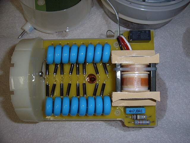
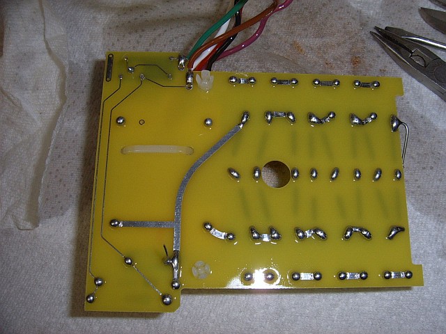
Trophy TRX708 X-Ray Generator
This is the head from a Kodak 2200 intraoral (dental) X-ray system.
See Trophy TRX708 X-Ray Generator Schematic.
The head contains the inverter and high voltage multiplier
with the wall-mounted controller housing the full-H-bridge high
frequency driver, timing, and safety circuits. Information on the
overall system may be found at
Kodak 2200 Intraoral X-Ray System User's Manual or if this link
should decay:
Sam's Copy of
Kodak 2200 Intraoral X-Ray System User's Manual. A Web search will turn
up other copies.
Obtaining Used X-Ray Equipment
(From: Kristian Ukkonen.)
You can find them from companies that sell x-ray equipment or
overhaul them. They will often get old ones when they sell new
ones that replace the old ones in hospitals etc.. Either they
storage them as spare-parts, or sell them to junk yards.
Shipping X-Ray Tubes (Inserts)
When the glass tube or insert is properly mounted inside an X-Ray head
or housing, it's very well protected from reasonable abuse, even by shipping
companies. However, the bare glass X-Ray tube (insert) itself is quite
fragile even from normal handling. In fact, it is the only relatively common
similar high tech item I know of that is more fragile than a laser tube.
In a rotating anode X-Ray tube, the heavy
anode/motor assembly - which may weigh several pounds - is attached to
the glass envelope only at one end with most of the mass at the
unsupported end. So, even though the glass is rather thick and would
normally survive some trauma, a relatively modest physical shock, especially
from the side, will cause the tube to fracture. Even if the metal
near the seal is modestly compliant and allows some flexing, the heavy rotor
is likely to smash into the glass due to its inertia if the tube is suddenly
moved sideways. Either way, the result is tube bits. :( :) To have any
chance of survival during shipping, the anode/motor assembly must either be
secured to a rigid structure as it is when mounted in the X-Ray head assembly
so that it can't flex with respect to the glass envelope, or the entire glass
tube must be packed with something like 12 inches of soft foam rubber all
around to minimize the g-forces when the box drops onto the sorting conveyer
from 10 feet up. And even this is no guarantee. The best approach may be
to build a shipping container that duplicates the mounting arrangement
inside an X-Ray head. But doing this without fancy machining capabilities
may be harder than it sounds.
Notes on Typical X-Ray Head Wiring
This is for a medium power Bennett X-Ray system but others should be similar.
Disposing of Possibly PCB Contaminate X-Ray Tube Oil
Your call. I suppose that a law breaking heathen *might* incinerated it
by simply pouring it on a good lumber scrap fire although I personally
would NEVER do such. :-) I have no doubt that burning will break down
PCBs as incineration is how the EPA wants it disposed of, but I don't
think I would want to stand around too close and breath the fumes.
Getting rid of that stuff to EPA spec. is an absurd pain. There are only
a few EPA certified incinerators in the country and it has to be sent to
South Carolina from here to be disposed of in an EPA certified manner.
Anyway,... tube? What tube? Who?... Don't recall meeting anyone by
that name. :)
Items of Interest
X-Ray Discovery Anecdote
(From: Someone who works at a major X-ray tube manufacturer.)
Concealing Electronics from X-Ray Examination
The following was posted to a scientific newsgroup:
How to Focus X-Rays?
(From: Tom Loredo.)