µSFPI1 consists of 3 parts:
- SFPI head using low voltage PZT: Anything that will scan 2 to 3
FSRs with less than 60 V p-p should quality. The one to be used for testing
is home-built with a hemispherical-confocal cavity with an effective FSR of
approximately 1.75 GHz. For these tests, only a single polarization mode
will be supported, but the extension to full dual polarization support
is straightforward.
- Atmega 328 Nano 3.0 with 0.96" OLED 128x64 pixel display: Firmware
written in C generates the ramp driver signal and implements a rudimentery
DSO.
- Source of 5 VDC power and optional boost converter: The Nano runs on 5 VDC. This can come from a USB port on PC, laptop, or USB backup battery pack, or a 5 VDC power or regulated DC wall adapter. The boost converter, if used, runs from the 5 VDC and provides 30 to 50 VDC for PZT ramp driver transistor.
The Arduino-compatible Atmega 328 Nano 3.0 for µSFPI1 provides the functions of both the ramp driver with an external high voltage transistor powered by a DC-DC boost converter if needed, and Digital Storage Oscilloscope (DSO) using a small OLED graphics display. It should work with home-built SFPI heads using PZT beeper elements as well as commercial ones like the SA-200 and others from Thorlabs. For these, a 5 V ramp may be sufficient eliminating the need for the boost converter and its components.
The current implementation runs at about 25 scans per second using the 64x128 pixel OLED. Since the display works like a DSO, this is way more than adequate since there is no flicker. Thus, even when scaled up to a large display in the future, the refresh rate should be acceptable. And of course, the $2 Nano is not exactly a stellar performer, so a higher performance microprocessor could be substituted if needed.
A complete pocket-size SFPI based on µSFPI1 could be built into a 1x2x4 inch case. :-)
This document provides a general descriptions of the the µSFPI1 hardware and firmware.
Specifications
-
HeNe Laser Assembly
The heart of this system is the HeNe laser, which includes the laser
tube itself, HeNe laser power supply, tube heater, and beam sampler and
photodiodes monitoring the two polarized modes:
- HeNe laser tube: The tube should be the common red (633 nm)
wavelength 5 to 10 inches (125 to 250 mm) in length with a TEM00 spatial
mode (not multimode). It must be random-polarized and well behaved - not
a flipper (though even some flippers can be stabilized without difficulty).
These tubes typically have a total power output of 0.5 to over 4 mW.
Barcode scanner tubes that will manufactured by the 100s of thousands
in the 1980s are generally suitable. Confirming non-flipper behavior
is easily done once connected to µSFPI1 with the GUI, or with
a polarizer and laser power meter. Commercial HeNe laser heads from/for
stabilized lasers like the Spectra-Physics 117/A and similar Melles Griot
05-STP-901 are compatible with these requirements.
For a bare tube, ballast resistor(s) and appropriate wiring will also be required. Laser heads may plug into the power supply directly, though adapters or some splicing may be required depending on the plug/sockets on each.
- Compatible HeNe laser power supply: This may be a bare "brick",
either AC or DC input, or a "lab-style" supply.
- Tube heater: Stabilization is achieved by controlling the
cavity length of the laser tube down to sub-micro precision. This
is done by heating the tube beyond where it would be with the discharge
current alone. The controller then maintains this exact temperature
by balancing heating due to power to the heater and cooling via
convection and conduction to the environment based on optical feedback. The
heater may be implemented by winding
insulated magnet wire around the tube or a Kapton thin-film heater
of appropriate size and resistance can be used. The Kapton heater is
definitely easier to install, but are expensive and/or simply
unavailable unless you find a bargain on eBay. But it must be
compatible in dimensions as well as resistance. The optimum specs
for a tube that is 1 inch in diameter and 6 inches in length would
be between 2 and 2.5 inches in length x 3.2 inches in width to just
circle the tube with little or no overlap. If using magnet wire, it
should be wound "Bifilar-style" to minimize any magnetic field. Bifilar
means that a pair of wires connected at one end are wound
continuously with both connections at the opposite end resulting
in nearly perfect cancellation of its magnetic field.
The cold resistance of the heater should be between 12 and 24 ohms.
For a tube that is 1 inch in diameter and 6 inches in length, the
use of #34 AWG wire (approximately 0.007 inches in diameter and 0.261
ohms/foot) should result in a 20 ohm solenoid of around 2 inches
in length. For a different size tube or different resistance or different
wire, you can do the calculations. :) It's desirable to have
the heater cover at least 1/2 of the available tube but keep away
from the high voltage. :( :) Having said all that, it's not critical
(except the avoiding the high voltage part!). It's even possible to
heat only one of both mirror mount stem but this can be tricky and
is left for the advanced course. ;-)
- Beam sampler and photodiodes: A polarizing beam-splitter
separates the P and S modes, and silicon photodiodes monitor each of these.
- Mounting: A suitable mounting scheme must be provided for these parts as well as a thermally leaky enclosure so that heat can flow to the environment. The mounting must be compliant as the tube does need to expand and contract, if ever so slightly. The heater should be covered by a small amount of insulation - a couple layers of plastic sheet would be suitable. The enclosure should not be sealed but must isolate the laser tube from air currents which will tend to upset the delicate balance for it to remain stable.
Wiring Diagram and Parts List
The diagram below - a sort of a hybrid between an electronic schematic and wiring diagram - shows the parts required for an Atmega328 Nano 3.0 system (with or without the GUI) incorporating all the bells and whistles. (Well at least the LEDs in decorator colors.) But for basic functionality, LEDs for Locked and Error would be all that's needed.

µSFPI1 Schematic/Wiring Diagram using Atmega 328 Nano 3.0
The following are the components required to put together a basic system for the controller. These parts are available from electronics distributors like Digikey and should total no more than around $10 to $15. The Atmega is available from many eBay sellers for as little as $2 delivered. This list does NOT include the laser and its associated optical and electronic parts.
- Atmega 328 Nano 3.0 development board. This comes assembled with
the microprocessor preprogrammed with the firmware uploader and
is available via eBay from USA sellers for around $5, or from the
Far East for $2.50 or less. These are probably all clones of the original
but appear to work fine. It can also be found via Amazon and the major
electronics distributors, as well as direct from Adafruit, usually for
much more. Regardless of which one you buy (if not from me), confirm
that it has the bootloader pre-installed.
µSFPI1 should run with at most minor modifications on other Arduino-compatible boards. I did attempt to get the GUI to run on the Pro Micro Atmega32U4, which is even smaller than the Nano. So, it really should be called Pico. ;-) But several issues stood in the way and that project has been shelved for now. The µSFPI1 controller (only, no GUI) does run on the femto-size ATtiny85. :)
Designing your own PCB is also an option but at these prices, it's hardly worth the effort unless the intention is to include it as part of a larger system.
- USB A male to USB B Mini male cable (for Nano, other styles for
the ATtiny or Pro Micro). This is used to upload the firmware and
run the GUI (if supported).
- Heater drive transistor. High gain NPN power transistor. Two
possibilities include the KSD2012GTU, LM395, or any other NPN power transistor
with a gain at 0.5 to 1.0 A of 100 or more. A base current limiting resistor
of around around 330 ohms will be required if using a conventional NPN
transistor. Using an N-channel MOSFET is
also possible but care must be taken to assure that the output drive voltage
from the Atmega digital pin is adequate to fully turn it on reliably.
This may require a buffer to boost it to 8 or 10 V.
A snubber circuit consisting of a 0.1 uF capacitor and 1 ohm resistor may be required to suppress a turn-off spike due to stray inductance. Aside from unsightly blemishes in the heater drive waveform, the absense of a snubber was resulting in peculiar behavior of the PWM drive and mode input signals.
- 2 x 1M ohm (typical) trim-pots to adjust the polarized mode sensitivity
along with 2 x 0.1 uF caps to minimize noise pickup. A pair of
trans-impedance preamps may be added where the highest level of
performance is desired.
- LEDs (optional) for hardware status indication. These can be dispensed
with if using the GUI exclusively, or where status is monitored by another
system. Then, perhaps keep Locked and Error LEDs, or none at all. But
then it would not qualify as an official digital system! ;-)
- 1 x green LED and 1 x orange LED for P-Mode and S-Mode indicators or Loop Difference indicator. Or a bicolor LED for the latter.
- 1 x yellow LED for heater drive indicator.
- 3 x LEDs for state indicators (your choice of color).
- 1 x blue LED for the locked indicator.
- 1 x red LED for Error indicator.
- 6 x 330 ohm 1/4 W resistors for LED current limiting except for Heater Drive, which should be 1 x 1K ohm.
- For Zeeman lasers or where monitoring of REF frequency is desired
(used solely for display in the GUI), additional components may be
required to convert the signal to TTL. The REF input (Arduino pin 5)
is configured with an internal pullup, so nothing special needs to be
done with it if not connected to anything.
- Solderless breadboard with 30 columns minimum or a custom PCB. ;-)
For those not familiar with the common resistor color code (Black/0, Blown/1, Red/2, Orange/3, Yellow/4, Green/5, Blue/6, Violet/7, Gray/8, White/9), the resistors shown above are 150 ohms (brown-green-brown or 15 with 1 zero) ohms and 330 ohms (33 with 1 zero) ohms. The gold stripe indicates 5 percent tolerance on the value but for the use here, tolerance doesn't matter. (It's possible the resistors you use will have 4 stripes where 3 of them are the value and the 4th is the multiplier, along with one for tolerance. If in doubt confirm the value with a multimeter.) The chart below is from Digikey. (If the link decays, a Web search will readily find another one.)

Resistor Color Code Chart (from the Digikey Web site)
The photo below shows the first version of µSFPI1. It matches the schematic/wiring diagram above except for some minor details like specific part values, lack of filter capacitors and snubber, resistors instead of trim-pots for mode gain, and differences in LED colors.
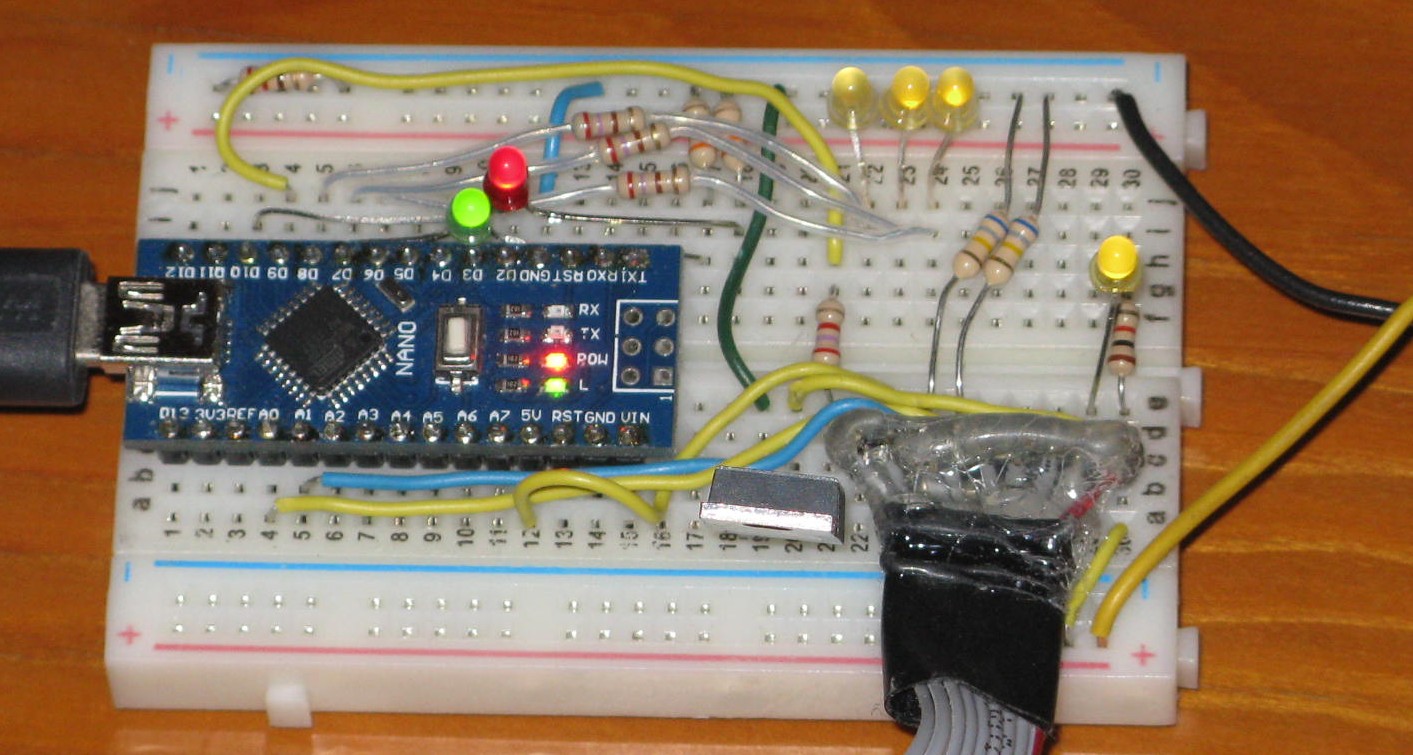
Prototype µSFPI1 using OLD WIRING - DO NOT COPY
Other parts like jumper wire (solid insulated #22-#26AWG for breadboard connections), cables to attach the PDs and heater, and connectors (if desired) will be required to complete the system.
Most of the connections on the breadboard are made with the electronic parts themselves or bits of excess wire cut from their leads. But there will be a need for a few insulated jumpers which should use #22-#24 solid hookup wire stripped to fit in the holes.
It may be desirable to wire the laser with the photodiodes and heater as a separate assembly, using some sort of connector to attach it to the controller. One suggestion is to use DB9F (controller) and DB9M (laser) connectors wired according to the Spectra-Physics 117/A pinout:
       Pin   Function
     ----------------------
        1    Heater
        2    Interlock
        3    Ground
        4    PD-P Anode
        5    PD-P Cathode
        6    Heater
        7    Interlock
        8    PD-S Anode
        9    PD-S Cathode
DC power supplies for the heater (12 VDC at 1 A max assuming a heater of not less than 12 ohms cold resistance) and the Nano 3.0 (5 VDC at less than 1/2 A, unless always connected to USB) will also be required.
CAUTION: The Nano 3.0 can take +12 VDC on VIN since it has an on-board 5 V regulator. But apparently there can be problems when connecting to USB as I found out. Inadvertent ground loops (or something) can result in erasing its brain or damaging the USB chip. Exactly why this occurred is still not clear. The NANO was connected to USB and then the 12 V adapter was plugged in, at which point the USB dropped out, never to be heard from again with this board. The regulated wall adapter was on the same circuit and isolated in any case, so it should not have caused problems. The Atmega microprocessor is still running something so it's not totally dead, thus the suspicion that the problem is the USB chip. But I've been unable to change it so far, even with a programmer. Until the cause can be determined and remedied, it is recommended that USB (or a USB wall adapter) be used to power everything but the heater, which can use its own supply. When used without USB, VIN can be connected to the heater supply if suitable.
Printed Circuit Board
A PCB is under development that may be used for a more permanent setup. It will have a DB9F that will be plug-compatible with the Spectra-Physics 117/A (and functionally identical Melles Griot 05-STP-901) laser heads. The circuit will be virtually identical to the one above, with just a few minor hooks for future enhancements.

Rough µSFPI1 PCB Layout Showing Controls, Indicators, and Connectors
The Nano 3.0 will be installed in a socket but everything else will be soldered. The 3 pin header is for power (+12V,GND,+5V Ext). The +5V Ext is optional for VIN rather than 12V. The 2 pin header is for the REF frequency input for use with Zeeman lasers. The PCB is 2x2 inches. The remainder of the board is taken up with mundane things like resistors and capacitors. ;-) Since its size is mostly limited by the Nano and DB9F, using SMT components would not be very beneficial and would make hobbyist assembly more of a pain.
Regardless of whether you decide to use the PCB, it is recommended that the system first be built up on the solderless breadboard to confirm that the default components are satisfactory. Depending on the specific laser tube, the waste beam (of sampled beam) may be lower or higher in power than what is optimal for the P-Mode and S-Mode adjustments. The snubber RC network may also need to be modified depending on the laser head cable length and type. Also, LED brightness can vary significantly and their current limiting resistor values may need to be changed (probably to higher values to reduce the brightness). Of course, there's no need to install all the LEDs but they do add class. :)
Atmega/Arduino Pin Assignments
Here is a list of the Atmega 328 Nano 3.0 external pins used by µSFPI1:
 Arduino Pin   Physical Pin   Function
--------------------------------------------------------------------------
     D3             6         P-Mode LED (5V PWM, 0 to 100 percent)
     D5             8         REF Frequency input (TTL 0 to ~6 MHz)
     D6             9         Heater Drive (5V PWM, 0 to 100 percent)
     D7            10         State bit 0 LED (0 or 5V)
     D8            11         State bit 1 LED (0 or 5V)
     D9            12         State bit 2 LED (0 or 5V)
    D10            13         Locked LED (0 or 5V)
    D11            14         S-Mode LED (5V PWM, 0 to 100 percent)
    D12            15         Error LED (0 or 5V)
    D13            16         Heartbeat LED (Atmega "L")

     A0            20         P-Mode input (0 to 5V)
     A1            21         S-Mode input (0 to 5V)
     A2            22         External Modulation input (future, 0 to 5V)

    +5V            27         +5 VDC from on-board regulator or USB
    VIN            30         Optional DC input (+7 to +20 VDC)
    GND           4,29        Ground/Common
See CAUTION above with respect to power.
Computer and Operating System Requirements
If I sell you the Atmega board, a version of the firmware will already be installed. Otherwise, a PC will be required to compile and upload the firmware. And since there will no doubt be numerous updates, this will be required in any event. :)
Latest Versions of the Firmware and GUI
Installing the Arduino Device Driver
Before the Atmega board can be used, a Windows device driver must be installed to enable upload of firmware and communications with the µSFPI1 GUI.There are many ways of doing this - some which may be overly complex, but what I've done for the Atmega 328 Nano 3.0 board is to go to Arduino Software and install the current version of the Arduino IDE (V1.6.9 as of May 2016). (I'm not sure if the board needs to be plugged in to a USB port during this process, but mine was. During the install process, it will ask to install the drivers. Reply "Yes" to all its requests. When the Arduino IDE is started for the first time, go to "Tools", "Board", and select "Arduino Nano". If the Nano is plugged in, its COM port should appear under "Tools", "Port". If you received the Nano from me, it will have µSFPI1 firmware. Go to "Tools", "Serial Monitor". The Serial Monitor windows should appear and after a few seconds start pumping out data from the board. Select a baud rate of 57600 to turn it into something meaningful. With no laser, the data should look something like:
 0 0 0 9745 8 6104
 0 0 0 9746 10 144
 0 0 0 9747 11 5
 0 0 0 9748 15 260
(The 4th value is a sequence number which should be incrementing by 1.)
More info on software, drivers, and more at Getting Started with Arduino and Genuino on Windows.
The more complex installations may be required if you bought the Nano from eBay or off the back of a truck, depending on whether it has the genuine FTDI USB communications chip. And even more complex if it doesn't have the bootloader installed. Links for driver installation may be found under References under "Arduino". Instructions for burning the bootloader may be found in the section: Burning Bootloaders into the Nano or Pro Micro.
The Arduino IDE can be used for compiling and uploading, though I prefer UECIDE, below, because compilation and uploading is much faster. For use with the Atmega328 Nano 3.0, either is fine. However the ATtiny and Pro Micro may only be supported by the Arduino IDE. (The latter may come up as Arduino Leonardo though.)
Loading UECIDE
UECIDE will work with all versions of the firmware. But the only version of UECIDE I've had success compiling firmware without errors is Version 0.8.8alpha17 though I assume that more recent versions like 0.8.8alpha22 should also be satisfactory. Assuming that, download it from UECIDE: The Universal Embedded Computing IDE. And other versions probably work, they just hate me. :( :) If for some reason 0.8.8alpha22 doesn't work for you, I can provide 0.8.8alpha17, but it probably won't work for you either. ;-)The UECIDE files should be unzipped to any convenient location on your computer. UECIDE requires around 160 MB there, and another 600+ MB for support files typically somewhere like c:\users\YourUserID\AppData\Local\UECIDE. This location can be changed in File->Preferences. If doing this after having configured UECIDE, copy all the files to the desired destination first, then change the data directory in File->Preferences. DO NOT delete the original UECIDE directory or the preferences file! :) Otherwise, the configuration information will all be lost.
Compared to most applications, UECIDE takes forever to start up even on a fast PC. So be patient. That's the bad news. The good news is that compiling and uploading takes literally only a few seconds, much faster than with the Arduino IDE or MPIDE (another one you don't need to know about). Go figure. :)
The first thing UECIDE will likely do is to tell you that no boards are installed and then open the Plugin Manager. If it does not, do it manually by going to Tools->Plugin Manager. At first the pane along the left will only show the word "Plugins". But after a couple minutes, it should update with a list: Plugins, Libraries, Boards, Cores, Compilers, System. The following are required:
- Libraries:
- No special libraries are required. EEPROM.h is used but is included by default.
- Boards: Arduino -> Arduino Nano w/ Atmega 328.
- Cores: Arduino 1.6.x.
- Compilers: GCC 4.8.1 for AVR
For each of these click on "Install". Installing the arduino board will probably automagically install the other related files and may take several minutes. Confirm that each entry has a green check mark next to it.
Close the Plugin Manager and go to "Hardware" or check the status line at the bottom of the window to confirm that the proper Board (Arduino Nano w/ Atmega 328), core (Arduino 1.6.x)), and Compiler (GCC 4.8.1 for AVR) has been selected. Correct it if not.
Some other quirks of UECIDE that I've found:
- Doing any File Open or Save As operations within UECIDE also take much
longer than directly in Windows. Be more patient.
- UECIDE will crash instantly and then will crash if restarted should the
selected data directory (in File->Preferences) be changed to one that is
read-only (as it might be on a remote host). There is no warning. Fix the
relevant entry in the configuration file, typically at
c:\users\YourUserID\AppData\Local\UECIDE\preferences.txt (unless you moved it)
using Notepad or any other convenient text editor.
Or delete the file (but that will require redoing all the plugin stuff.
- On one PC, the USB mouse would freeze for a couple seconds preiodically
whenever UECIDE was running making it almost impossible to do anything, and
it continued even if UECIDE was minimized. This appears to be related
to the "Automatic USB Device Discovery" option being enabled (the default)
and some peculiarity of the PC's USB subsystem and Window. To remedy it,
stop USB Device Discovery by going to Tools->Service Manager and clicking
on its entry, click on the stop icon, and disable Autostart by right-clicking
on the "yes" to change it to "no". Then close and restart UECIDE. Despite
what it says, the discovery process does not stop even though it says it's
stopped until the next time UECIDE is run. Got that? :) Or drag out and
dust off a PS2 mouse. :-) This glitch went away after upgrading to Window 10.
- Occasionally out of the blue (even if not using it) UECIDE will put up a message along the lines "I'm afraid UECIDE has Crashed" with several options. Usually hitting "Ignore" will allow it to continue as though nothing happened.
Plug the Atmega board into any available USB port. The power LED should come on. If I (Sam) sent you the Atmega board, it will have been loaded with a version of the µSFPI1 firmware and the user LED will be flashing at about 5 Hz rate to let you know it is alive. But by the time you've received it, the firmware will probably be out of date, so reloading will be required in any case. :)
Assuming the driver has already been installed, go to Hardware->Serial Terminal and select its COM port. Typically, this will be the highest number COM port, or perhaps the only one, since no one uses real COM ports for much of anything anymore.
UECIDE should remember the configuration settings automatically upon exiting. These are tied to each instance of the UECIDE window, so it's possible to easily deal with multiple totally different board types.
Uploading the µSFPI1 Firmware
The firmware is provided as a source file which probably has an extension of ".ino" (though the specific name doesn't matter - it's just a text file). However, the name may NOT contain any dashes "-" due to the peculiar restrictions of Java or something. Make a directory with the name of the firmware (without the extension) and put the firmware file there. For example, if the file is named uSFPI1_FW_v123.ino, make a directory called uSFPI1_fw_v123. and put uSFPI1_FW_v123.ino in it. Note that case matters so the name of the directory and name of the firmware file (without the extension) must match case character-by-character exactly. Thus uSFPI1_fw_v35.ino is not the same as uSFPI1_FW_v35.ino.
- Plug the Nano 3.0 board into a USB port. Windows should recognize it
with the usual annoying sound of a USB device it recognizes. I've
occasionally seen problems using a USB port replicator though these
generally are acceptable. But if the board doesn't come up, plug it into
a direct USB port.
- Use Ctrl-O to open the firmware file.
Select the directory. The source code should
appear in the same window unless a file is already open, in which
case a new window will appear. (If UECIDE thinks it's a firmware
directory, it won't even allow you to select the file but
will immediately open it. If the name of the directory and
file don't match - including case - it will produce an error like
"file not found". What a concept? ;-)
- Use Ctrl-U to compile and upload the firmware to the board. This
typically takes only a few seconds on a PC that is less then 35 years old. :)
Near the end, the green status bar will extend nearly all the
way to the right and the LEDs on the board will then begin
flashing in several different patterns in anticipation of
getting new and (hopefully) improved firmware. ;-)
The board will be automatically reset and start running the firmware.
During this time, confirmation messages similar to the following will appear:
   Compiling...
     * Compiling sketch...
     * Compiling core...
       > arduino
     * Compiling libraries...
     * Linking sketch...
   Compiling done.
   Memory usage
     * Program size: 7532 bytes
     * Memory size: 1092 bytes
     * Compilation took 8.634 seconds
   Uploading firmware...
     * Resetting board...
     * Uploading...
     * Resetting board...
     * Upload Complete
Once the firmware has started, the on-board LED "L" should be flashing at a 5 Hz rate to let you know it's alive.
The firmware is retained in non-volatile memory so uploading only needs to be done once - or until a new version is available!
Uploading new firmware does not affect the user locking parameters stored in Atmega EEPROM. However, should the format change (rarely), the firmware will revert to the default locking parameters. In that case user parameters that differ from the defaults will need to be re-entered via the GUI Command window and then saved.
The firmware may also be compiled without uploading by using Ctrl-R. Since you haven't messed with the code, it should compile without errors. This is slightly faster for testing and doesn't use the board at all so it can be off doing whatever it pleases. :)
Installing and Running the µSFPI1 GUI
Note that µSFPI1 does not require the GUI to control the laser, but it is convenient for troubleshooting and/or fine tuning locking parameters.Save the µSFPI1 GUI .exe file into any convenient directory. (There's a small chance that the first time it's run, an error is produced since there is no configuration file associated with it. Simply continue and the GUI will come up. When it is closed using "Finish", valid settings will be saved so that the error should ot appear again.)
Important: DO NOT reset the board while the µSFPI1 GUI is running. The GUI will need to be aborted, the board may need to be reset again, and only then can the GUI be restarted. However, the GUI may be aborted and restarted ad-infinitum without affecting the firmware and laser. ;-)
The graphic below shows the typical GUI main window at startup.

Typical µSFPI1 Main Window at Startup
Yes, this bears remarkable similarity to the µMD1 GUI due to having inhereted much of its DNA. ;-) When first started, all the readouts are loaded with zeros and the fake LEDs are turned on to show that they are there. Sort of a high tech "lamp test". ;-)
GUI Operation
The µSLCS1 GUI (henceforth simply called the "GUI") comes up with the P-Mode amplitude in the main readout. The only action required by the user is to select the USB COM port. Once selected, the readouts and graph will begin displaying the data from the laser. Behind the scenes, the GUI has uploaded the Locking Control Block from the firmware to update its widgets with the current set of locking parameters.Important: The GUI can be started at any time but the firmware must be running before the USB COM port is selected or else the Universe may implode or explode, which one occurs and when has yet to be determined. :) Confirmation of this issue is left as an exercise for the user. ;-) There should be no need to reset the firmware when restarting the GUI - it will pick where it left off.
Note that the GUI is NOT required to run the laser with the µSFPI1 controller and starting or restarting the GUI has absolutely no effect on laser behavior. (Or at least it shouldn't.) Unless messing with the parameters in the "Laser Firmware Hacking" (Command) window, which will be explained below. For most users, the GUI will only be used to monitor the laser. Actually, for most laser users, there is no need for the GUI at all! It's been developed primarily as a development aid and for unapologetic laser jock technoduibes. ;-)
Main Window Controls and Indicators
All possible controls and indicators are shown below.

All µSFPI1 Main Window Controls, Readouts, LEDs, and Graph
The first set are the selection buttons at the top of the window. Note that except for USB Port, these do not invoke drop-down menus and require only a single click to activate.
- Finish is the same as close or exit. :)
- Open Log File is used to select the (optional) file for data
capture. This is a text file that will accumulate raw data from the
USB COM Port when capture is enabled. When a log file is open, the
button's label will change to "Close Log File".
The log file is closed and its name and path are saved upon exiting the GUI.
- Command opens a window to allow laser jock access to the firmware
locking parameters. Nearly everything that determines locking bahavior
can be modified, and most such changes are likely to be less than beneficial.
Thus the use of this "feature" should be avoided by ordinary mortals. ;-)
- Help is a menu that may select "Information" which presently
tells the user to read this manual ;-) or "About" which lists the
GUI and firmware versions, and has links to the author.
- USB Port provides selection of the USB COM port for the laser conctroller. Note: Once a USB port has been opened, the selection cannot be changed or closed. Code to close an open USB port is purported to do bad things (also with ramifications for the future of the Universe) and has been disabled. If an incorrect USB port was selected by accident, exit the GUI and restart. Any open USB port will be closed upon exiting.
These buttons may all be accessed via Alt-first letter.
The next set are the buttons for selecting what's shown in the Main Readout and what is plotted:
- P-Mode: selects the P-polarized mode amplitude for display in
the Main Readout. P-Mode and S-Mode are superimposed on the plot.
- S-Mode: selects the S-polarized mode amplitude for display in
the Main Readout. P-Mode and S-Mode are superimposed on the plot.
- Loop Difference: selects P-Mode minus S-Mode plus Offset if in
Lock Type = Frequency or P or S Mode minus Reference Level if
Lock Type = Intensity for display in the
Main Readout and the plot. This is also the loop error signal used for
stabilization, but calling it "Loop Error" or "Mode Error" risks stirring
fear in the hearts of laser nerds. ;-)
- Heater Drive: selects the power to the tube heater for display
in the Main Readout. Heater Drive is shown in the plot.
- Disable Graph toggles whether to show the graph or not and will
change to "Enable Graph" when the graph is off. The data for
the graph is still stored when disabled. Disabling the graph
both saves space on the computer screen and reduces computational load.
- Enable Capture toggles the acquisition of raw data from the
USB COM port. The log file must first be opened for this button to have
any effect. Then, the label will change to "Disable Capture" and the
button will turn green signifying that capture is enabled and running.
Once the log file is open, capture may be turned on and off at will
with data appended to the open log file. Prior to each segment, the
line "Sample Frequency = XX.XX Hz" is stored. This value may be useful
for data analysis. The Sample Frequency is approximately 61 Hz.
The log file format is: PM:P-Mode SM:S-Mode HD:Heater Drive SN:Sequence Number LSC:Low Speed Code LSD:Low Speed Data.
      Item       Abbrev    Data Range    Value Range
 -------------------------------------------------------
     P-Mode        PM       0 to 1023     0 to +5 V
     S-Mode        SM       0 to 1023     0 to +5 V
  Heater Drive     HD        0 to 255   0.0 to 100.0 %
  Sequence Number  SN        0 up :-)   Time * 977 / 16
  Low Speed Code   LSC      16 bit int       --
  Low Speed Data   LSD      32 bit int       --
Low Speed Code and Low Speed Data are used to return information that doesn't need to be displayed at the sample rate like State, Lock Time, and firmware version, and read back the locking parameters from the firmware, and monitor other aspects of the firmware.
A typical snapshot of a logfile is shown below:
   Sample Frequency = 61.04 Hz

   PM:594 SM:601 HD:142 SN:9743 LSC:0 LSD:0
   PM:596 SM:604 HD:142 SN:9744 LSC:12 LSD:1590
   PM:599 SM:606 HD:142 SN:9745 LSC:8 LSD:6104
   PM:598 SM:604 HD:143 SN:9746 LSC:10 LSD:144
   PM:594 SM:600 HD:143 SN:9747 LSC:11 LSD:5
   PM:596 SM:604 HD:142 SN:9748 LSC:15 LSD:260
   PM:600 SM:604 HD:143 SN:9749 LSC:0 LSD:0
   PM:599 SM:604 HD:143 SN:9750 LSC:0 LSD:0
   PM:599 SM:605 HD:143 SN:9751 LSC:0 LSD:0
   PM:599 SM:606 HD:142 SN:9752 LSC:0 LSD:0
   PM:596 SM:601 HD:143 SN:9753 LSC:101 LSD:0
   PM:596 SM:601 HD:143 SN:9754 LSC:102 LSD:0
   PM:597 SM:600 HD:144 SN:9755 LSC:103 LSD:0
   PM:597 SM:601 HD:143 SN:9756 LSC:104 LSD:2
   PM:597 SM:602 HD:143 SN:9757 LSC:105 LSD:1
   PM:596 SM:601 HD:143 SN:9758 LSC:20 LSD:0
   PM:598 SM:603 HD:143 SN:9759 LSC:0 LSD:0
   PM:599 SM:604 HD:143 SN:9760 LSC:12 LSD:1593
   PM:596 SM:600 HD:144 SN:9761 LSC:8 LSD:6104
The Sample Frequency is 1/16th of the firmware control loop update rate derived by: 16 MHz (Atmega I/O Clock) / 64 / 256 = 976.56 Hz. 976.56 Hz / 16 = 61.04 Hz.
- Averaging adjusts the "strength" of a moving average from 0 (no
averaging) to 0.999 (1000 samples of averaging). It is a logarithmic
scale so each third of movement represents approximately a factor of 10.
The color also changes from black to violet to remind you that averaging
is taking place. :)
The Averaging coeeficient is saved upon exiting the GUI.
- Graph Averaging On checkbox determines whether averaging is
also applied the graph. Thus the graph can show raw data even if the
readout is averaged.
- Time Compression applies a sub-sampling factor to change the
rate of the graph scrolling. It does NOT average intermediate samples -
they are lost. The legend at the bottom of the plot shows the approximate
time between adjacent vertical lines for new samples like a quaint
paper strip chart recorder. :)
The Time Compression factor is saved upon exiting the GUI.
- P-Mode and S-Mode, Loop Difference, and Heater Drive Range select the vertical axis scaling for their respective values. It's unlikely that anything other than the defaults of 5V, 5V, +/-5V, and 100% will ever be needed except perhaps for Loop Difference, which should hover around 0 when the laser is locked, but will change dramatically if one abuses it. :( :)
Main Window Indicators
Next are the various fields for displaying information in the Main Window:
- Main Readout always shows the value of the parameter selected
by the 4 buttons.
- P-Mode readout and PM LED (Green): display the amplitude of the
P-polarised output from the laser tube with no averaging. The units are
volts based on the input to the Atmega pin. The LED has a
logarithmic response to stretch low values to be more readily visible.
- S-Mode readout and SM LED (Orange): display the amplitude of the
S-polarised output from the laser tube with no averaging. The units are
volts based on the input to the Atmega pin. The LED has
a logarithmic response to stretch low values to be more readily visible.
- Loop Difference readout and LD LED (Green/Orange): display the
amplitude of the loop difference signal with no averaging. The units are
volts. The response of the LED is boosted by a factor of around 20 so
+/-0.25 V will be result in maximum brightness and very small values
of Loop Difference can be seen. The displayed loop difference depends
on Lock Type as follows:
- Frequency: P-Mode - S-Mode + Offset.
- Intensity P-Mode: P-Mode - Reference Level.
- Intensity S-Mode: S-Mode - Reference Level.
- Heater Drive readout and HD LED (Yellow): display the amplitude of
heater drive signal with no averaging. The units are percent and is linear
with power. The LED has a logarithmic response to stretch low values
to be more readily visible.
- REF Frequency: displays the frequency of the reference (or other
TTL) input signal for use with Zeeman HeNe lasers. The range is from 1 kHz
to around 6.5 MHz with an accuracy better than a fraction of 1 percent.
(The accuracy is determined by how close the Atmega I/O Clock is to
16 MHz.) The REF frequency
readout will appear under the LED strip if a signal is detected on the
REF input pin. The title at the top of the Main Window will also
become: "Micro Stabilized Two-Frequency Zeeman Laser Controller GUI".
These changes will remain in effect until exiting the GUI even if the
REF signal disappears.
- State: identifies exactly what the firmware is doing at any
time once the USB Port is open. The following assume default values
for locking parameters. (More on this below.)
- State 0 - Startup: The firmware is checking that the laser is
lit as determined by at least approximately 10 percent of maximum possible
amplitude on either the P-Mode or S-Mode signals. Go to State 1
It will wait in State 0 up to 120 seconds for a slow-start tube,
else go to State 7.
- State 1 - Warmup: The firmware turns on the heater at full
power and measures the period of the P-Mode sweep. It will remain here
until it exceeds the parameter "Mode Period", which has a default
value of around 16 seconds. At this point, the tube should be warm enough
to be locked near an optimal temperature. Go to State 3.
- State 2 - Heating: The firmware turns on the heater at full
power for a fixed length of time, then goes to State 3.
- State 3 - Locking: The firmware runs a proportional-only locking
algorithm to stabilize the laser. Once the absolute value of the Loop
Difference (based on P-Mode - S-Mode amplitudes) has not changed more than
the Lock Tolerance threshold for Lock Valid seconds, check the heater
power. If within a few percent of 50%, go to State 3; if less than
45-48%, go to State 2 (heating), if more than 52-55%, go to State 4
(cooling). The default durations for heating and cooling differ by
4:1 so that getting into an infinite loop is unlikely. :)
- State 4 - Cooling: The firmware turns on the heater at zero
power for a fixed length of time, then goes to State 3.
- State 5 - Locked: The firmware runs a PID algorithm and
is now stable. It will remain here forever, more or less. :)
- State 6 - Hangout: This is a testing state that can be used
to set the heater to a constant value for an unlimited time.
- State 7 - Error: Stick here if error occurs. Definition of
lock type "error" remains under review but currently includes:
- Taking too long for the laser to come on in State 0.
- Loop Difference never going negative in State 1.
- S-Mode or P-Mode dropping below 5 percent or going above 95 percent in State 5 (which means it's really not locked).
- Taking too long to lock in State 3.
Exit from State 7 to State 0 if no laser light after a long time, or to State 1 if the laser beam reappears. The firmware is persistent though - it will keep trying for a long time. :-) There is no error checking in States 2, 4, or 6.
Before a USB port is selected, State will display "No Laser".
- State 0 - Startup: The firmware is checking that the laser is
lit as determined by at least approximately 10 percent of maximum possible
amplitude on either the P-Mode or S-Mode signals. Go to State 1
It will wait in State 0 up to 120 seconds for a slow-start tube,
else go to State 7.
- Sir HeNe: provides visual feedback on the laser's physical
and emotional well being. ;-)
- Locked LED (LK, Blue): will be on when the laser is in the
Locked state. This does not necessarily mean the laser is stable, just
that it thinks it should be. ;)
- Error LED (ER, Red): will be on if there is a problem
with the laser. Typically this would mean there is no laser output or
for some reason it is not possible to lock. The LE LED may cycle on
and off as the controller attempts to remedy the situation (or is just
overly optimistic).
- Lock Type: Identifies whether the laser is locking the
Frequency (dual mode stabilization) or Intensity using only the
S-Mode or P-Mode (single mode stabilization).
- Lock Side: Which side of the neon gain curve to use for locking.
The default is "Red", though what actually happens for
staiblization will depend on the choice of S-Mode and P-Mode polarization
that exits the laser. Figuring out how to determine this is which is
above my pay grade :)
- Mode Offset or Reference Level: Which label is shown depends on
the Lock Type. Normally, the ideal lock point
for a Lock Type of Frequency will be where the P-Mode and S-Mode amplitudes
are exactly equal. However, it is possible to shift the lock point
either way by specifying an Offset (see below) or via the External
Modulation input (future. For a Lock Type of intensity, the Reference
Level represents the selected output amplitude.
- Total On Time: Run time (hh:mm:ss) since power on (or firmware
reset or reload).
- Locked at: The last time at which the laser entered State 5.
The typical lock time for first lock from a cold start is typically
under 15 minutes. :) However, if the Relock Counter is greater than 0,
it may retune the lock point at Relock Count times the Relock Delay after
this (and the "Locked at" time will be updated accordingly).
- Log File displays the name of the current open file for data capture. The Capture button will only have an effect if a log file is open.
When the firmware is started (power on to the board, reset, or just after the firmware is uploaded), the controller enters State 0, Startup. When it detects laser output, it goes to State 1 which drives the heater at full power while monitoring the length of the mode sweep cycle.
The graphic below shows a snapshot of the Main Window about halfway through warmup. The mode sweep cycle at this point is around 8 seconds.

Typical µSFPI1 Main Window about Halfway through Warmup
Once the mode sweep cycle time exceeds the "Mode Period" value, the controller goes to State 3, Locking. There it checks for the Loop Difference to settle down below the "Locking Tolerance" value. It then goes to State 5, Locked.
The graphic below shows a snapshot of the Main Window just after the laser has locked. On the left portion of the graph is the laser mode sweep of the P-Mode and S-Modes prior to locking.

Typical µSFPI1 Main Window shortly after Locking
The laser will remain locked forever unless the P-Mode or S-Mode go bonkers (technical term!). If it does go bonkers, the controller will go to State 7, Error and try again.
Data from the Atmega board is sent at a rate of just over 60 pps. However time compression of the plot may be set up to 1,000 so that more than 2 hours of data may be visible. At a complression of 5, the time between horizontal divisions is close to 10 seconds. While the data is subsampled, not averaged, graph averaging can do something similar.
Laser Firmware Hacking (Command) Window
The Command windows provides access to most of the parameters that affect locking behavior. While the basic locking algorithm and its state machine cannot be changed, it can be directed to go to any state and values to adjust the P-Mode and S-Mode gain/offset, PID gain coefficients, locking error bounds and timing, etc. can be entered. Changes may then be saved to non-volatile memory in the Atmega chip.The way these affect the firmware operation differ based on whether it is a state change or parameter change:
- State changes are at the top of the window. A specific state can be
selected (e.g., Warmup) which will reveal up to 2 state-specific
parameters. In the case of warmup, these are "Duration" and "Mode Period",
which will be described below. State changes (along with their
parameters) do not take effect until the "Send State Change" button
is clicked. But the laser will start using the parameters for the given
state (if and when it gets to it) as soon as the "Send State Parameterss"
button is clicked.
- Changes to the parameters in the lower part of the window will take effect immediately when a widget is clicked (up or down, but not by simply changing its value directly). Thus, for example, it will be easy to see what effect the Proportional Gain factor has on the stability of the laser if perturbed when in the locking or locked state.

Typical µSFPI1 Command "Laser Firmware Hacking Window"
CAUTION: Messing with many of the following will result in a laser that never stabilizes (at least until the firmware is restarted or reset to default values). However, permanent damage to anything but your ego is unlikely.
State Commands (and their parameters)
- Startup (State 0): The controller waits for the laser to come on
and then goes to State 1..
- Duration0 (Timeout): This is The length of time to wait for the laser tube to come on before considering it an error and going to State 7.
State 0 will remain in effect for a minimum of 2 seconds simply to enable it to appear in the State LEDs or GUI. :)
- Warmup (State 1): The tube heater is driven at maximum power
until the period of a mode sweep cycle exceeds the Mode Period value.
- Duration1: The length of time to remain in State 1
before giving up and going to State 7).
- Mode Period: The minimum length of time for the period of the Mode Error signal to reach before considering the laser to be warm enough to lock at close to an optimal temperature and going to State 3.
- Duration1: The length of time to remain in State 1
before giving up and going to State 7).
- Heating (State 2): The tube heater is driven at a fixed power
for a specified time and then goes to State 3.
- Duration2: The length of time to remain in State 2.
- HeaterDrive2: The value to use for the heater power. The default is 100 percent.
- Duration2: The length of time to remain in State 2.
- Locking (State 3): The difference between P-Mode and S-Mode
(Mode Error) is used as the control variable in a proportional feedback
loop. If the lock point results in heater drive more than a few percent
above 50 percent, go to State 4 (Cooling). If the lock point resuilts in
a heater drive of more than a few percent below 50 percent, go to State 2
(Heating). If within the Locking Tolerance after Lock Valid Duration
seconds, go to State 5 (Locked). Locking Tolerance serves a dual
role: It is the maximum change in the lock point permitted before
the lock point is checked against it.
- Duration3 (Lock Valid Duration): How long the Mode Error must be
within +/- of the same Lock Tolerance.
- Locking Tolerance: The maximum change in lock point permitted before the lock point is compared with the 50 percent heater drive and then considered close enough to lock if the difference is less then Lock Tolerance.
- Duration3 (Lock Valid Duration): How long the Mode Error must be
within +/- of the same Lock Tolerance.
- Cooling (State 4): The tube heater is driven at a fixed power
for a specified time and then goes to State 3.
- Duration4: The length of time to remain in State 4.
- HeaterDrive4: The value to use for the heater power. The default is 0 percent.
- Duration4: The length of time to remain in State 4.
- Locked (State 5): The laser is considered stable. There is an
option to check for optimal heater power (50 percent) periodically by
going back to State 3. The default is 1 relock 5 minutes after initial
locking, but the count can be increased or set to 0. One or more Relocks
may be beneficial when the laser stabilizes from a cold start as the tube and
enclosure come to thermal equilibrium.
- Duration5 (Relock Delay): The number of seconds to wait before checking
lock quality by going back to State 3.
Relock Count: The number of times to attempt relock.
- Duration5 (Relock Delay): The number of seconds to wait before checking
lock quality by going back to State 3.
- Hangout (State 6): Drives the heater at a fixed power level
for up to a very long time.
- Duration6: Currently ignored. ;-)
- Heater Drive: Power level for heater.
- Duration6: Currently ignored. ;-)
- Error (State 7): This is where the controller goes when something
screws up. :) It is currently similar to State 0 in that it will check
for laser light and go to State 1 if it finds any.
- Duration7 (Retry Delay): How long to wait for the laser to come on before going to State 0.
Note that for States 2, 4, and 6, if the heater drive is selected to be other than 0% or 100%, the value displayed in the Heater Drive readout(s) may differ by a fraction of 1 percent from the requested power due to roundoff error in conversion from the range of 0 to 100% that us humans understand to the PWM range of 0 to 255 and back again. Live with it. :)
If none of the state or locking parameters (below) have been changed, restarting (going to State 0 or resetting or reloading the firmware and GUI) will generally restore your laser to supreme happiness (assuming it ever was supremely happy). ;-)
Firmware locking parameters
These take effect as soon as a widget is "clicked" (up or down), but not by simply changing its value.
- Lock Type: Selects Frequency (dual mode), Intensity P-Mode, or
Intensity S-Mode. The intensities are referenced to the adjusted P-Mode
or S-Mode amplitude (see below). The Mode Offset or Intensity Level
controls will have an effect as appropriate. If Lock Type is changed while
the laser is in the Locking or Locked state, it will attempt to relock
based on the new selection.
- Lock Side: Which side of the neon gain curve to use for locking.
The default is "Red", though what actually happens for
staiblization will depend on the choice of S-Mode and P-Mode polarization
that exits the laser. Figuring out how to determine this is which is
above my pay grade :) so if it doesn't do what you think it should,
try the other choice. ;-) Note that if Lock Side is switched while the laser
is in the Locking or Locked state, it will relock on the opposite side of
the gain curve.
- Mode Offset: When the Lock Type is set to Frequency,
Mode Offset adds a fixed value into the mode difference
so that the lock point may be moved around on the gain curve.
The laser will remain in the Locked state for small changes in Mode Offset.
- Reference Level: Wheh Lock Type is either Intensity P-Mode
or Intensity S-Mode, Intensity Level sets the intensity
lock point. The level is refernced to the adjusted P-Mode or S-Mode
amplitude (see below).
- P-Mode Minimum and Maximum may be used to fine tune the
P-Mode signal to the input range of 0 to 5 V.
- S-Mode Minimum and Maximum may be used to fine tune the
S-Mode signal to the input range of 0 to 5 V.
- Proportional Gain is the "P" coefficent of "PID". A higher value
will speed up loop response but increase the tendancy to be underdamped,
and at too high a value, to oscillate.
- Integral Gain is the "I" coefficent of "PID". A higher value
will speed up loop response but increase the tendancy to be underdamped,
and at too high a value, to oscillate. The integral term removes any
offset forcing the Mode Error to be 0.
- Differential Gain is the "D" coefficent of "PID". A higher value will speed up loop response to changes may result in instability. (Not currently implemented at all.)
Load/Save
The parameters that control locking are stored in the Atmega. There are three 32 word data structures:
- Locking Control Block (LCB): This set of parameters is
used for locking. These can be changed by the GUI and any chnages
may take effect immediately depending on what the firmware is
actually doing at the time.
- Default Control Block (DCB): This set of parameters is what's
coded into the firmware and cannot be changed by the µSFPI1 GUI.
- User Control Block (UCB): This set of parameters may be saved to the non-volatile EEPROM of the Atmega.
For reference, the LCB, DCB, and UCB format is as follows:
 Location   Parameter           Range/Value
-------------------------------------------------------------------
     0      EEPROMFormat        Firmware compatibility value
     1      PmodeMin            0 to 818 for 0 to 4 V (0 V)
     2      SmodeMin               "              "   (0 V)
     3      PmodeMax            205 to 1023 for 1 to 5 V (5 V)
     4      SmodeMax               "              "      (5 V)

     5      ModePeriod          10 to 1800 for 1 to 180 s (14 s)

     6      ControlRegister     Lock Side:
                                  Bit 0 = 0: Red
                                  Bit 0 = 1: Blue

                                Lock Type:
                                  Bits 2:1 = 00: Frequency
                                  Bits 2:1 = 01: Intensity P-Mode
                                  Bits 2:1 = 10: Intensity S-Mode

     7      LockingTolerance    1 to 511 (8)
     8      ReLockCount         0 to 9999 (1)

     9      ProportionalGain    0 to 32 (10)
    10      IntegralGain        0 to 32 (10)
    11      DifferentialGain    0 to 32 (0, presently ignored)

    12      Duration0            10 to 6000  for  1 to  600 s (120 V)
    13      Duration1           100 to 18000 for 10 to 1800 s (180 V)
    14      Duration2            10 to 6000  for  1 to  600 s (30 V)
    15      Duration3            10 to 3000  for  1 to  300 s (20 V)
    16      Duration4            10 to 18000 for  1 to 1800 s (15 V)
    17      Duration5           300 to 18000 for 30 to 1800 s (300 V)
    18      Duration6            10 to 18000 for  1 to 1800 s (360 V)
    19      Duration7            10 to 18000 for  1 to 1800 s (120 V)

    20      HeaterValue0        0 to 100 percent (0 %)
    21      HeaterValue1           "        "    (100 %)
    22      HeaterValue2           "        "    (100 %)
    23      HeaterValue3           "        "    (50 %)
    24      HeaterValue4           "        "    (0 %)
    25      HeaterValue5           "        "    (50 %)
    26      HeaterValue6           "        "    (0 %)
    27      HeaterValue7           "        "    (0 %)

    28      Spare1

    29      Offset              0 to 1023 for 0 to 5 V (0 V)
    30      Intensity              "              "    (2.5 V)

    31      CheckSum            Not implemented
Ranges and default values subject to change without notice. ;-)
When the firmware starts, the DCB is copied to the LCB unless a valid UCB has been saved, in which case it is copied to the LCB. The LCB is then read out of the Atmega over USB into the GUI Command Window widgets.
- Load Default Parameters: This button will load the
original parameters. The Default Parameters are hard-coded into
the firmware and can be changed only before compiling and
uploading the firmware. The "Save Parameters" command
must be issued to then store these in non-volatile memory and replace any
User Parameters that were previously saved.
- Load User Parameters: This button will load previously saved
(and possibly changed) parameters. If the EEPROM does not have valid
User Parameters, nothing will be loaded or changed.
- Save User Parameters: The locking parameters currently in use (including any that were sent) are saved to non-volatile memory. These will be retained if power is removed and if new firmware is uploaded that has the same EEPROM format. (Frequent changes to the EEPROM format are not likely.) Note that any changes made to parameters associated with States that may have been changed but NOT sent will NOT be saved.
Note that while there is no way to save the locking parameters to a file explicitly (and there never will be!), a record can be made of them by starting the GUI, opening a log file, enabling capture, and then opening the USB Port. The first thing the GUI does is to upload the LCB in use from the firmware which will show up in the log file as a consecuative 32 sample block near the start with Low Speed Codes from 130 to 161. Reformatting as desired is left as an exercise for the determined student. ;-)
The next set of widgets are for diagnostic purposes. If they don't seem to make any sense, that's by design and it shouldn't keep you up at night. ;-)
- Firmware Directive Sent is the actual ASCII string sent to the
firmware for a state change, parameter click, etc.
- Command, Param 1, Param 2, Param 3 are what the firmware received
and returned to the GUI.
- Value 0, Value 1, Value 2, and Value 3 are integers which may be
assigned to arbitrary variables in the firmware. Value 0 is always
the total time in 10ths of a second that the firmware is in the current
state. The others are unique for each state.
- Main Window Diagnostic Readouts Checkbox determines whether
the four values - Diag 1, Diag 2, Diag 3, and Diag 4 - at
the top of the Main Window show up. If they are
visible, they will probably make even less sense than the above. :)
The state of this Checkbox is saved when the GUI is terminates.
And finally, the quickest way out of the hacker's window:
- Close: closes the Command window without performing any additional
actions. Any changes will be retained as long as the GUI is running.
But NOTHING IS SAVED to non-volatile memory. Any changes made to locking
parameters that were not previously saved (or sent at all) will be lost
when the GUI is terminated.
However, the Command Window does NOT need to be closed to do things in the Main Window.
If any of the parameters have been modified in the GUI and sent to the firmware but not saved, exiting the GUI (X or Finish) will ask if they should be saved before actually relegating them to the bit bucket. However, even if not saved, they are still in Atmega memory as long as the board hasn't been reset or power cycled. So, if the GUI is restarted, they will be retrieved automagically and can still be saved via the Command window. :)
Note that any changes made in the Command window before opening the USB Port will be lost when it is opened and the LCB is uploaded automatically from the firmware.
Troubleshooting
Naturally, all is expected to go smoothly. But if it doesn't, here are some common problems. Some of these may be bugs in the firmware or GUI as hard as that is to believe. So, if you find something that cannot be solved based on what's below, contact us for a timely response:Note: The following assumes the use of the Atmega Nano 3.0 board. If you've somehow figured out how to get the Pro Micro, change any references below to pins as appropriate. If you're using the ATtiny, there is no GUI support, period. So any failure of the GUI to do anything is a feature, not a bug. ;-)
The first set of problems deal with the board independent of the GUI and assumes that all the LEDs are present. However, some also apply to the readouts of the GUI. "LEDs" below refer to either physical LEDs or the fake ones of the GUI, as appropriate. ;-)
- Firmware will not load - "No suitable device": This
usually means the incorrect USB port has been selected or the Atmega
board does not have a bootloader installed. Sometimes, it could be due
to a bad USB cable, or attempting to upload through an incompatible USB
port replicator or hub.
- P-Mode and/or S-Mode or Loop Difference LEDs are not changing:
The firmware monitors the S-Mode and P-Mode inputs in all States.
Check the voltage to Arduino pins A0 and A1. They should be varying
within the range of 0 to 5 V. Adjust the respective Gain trim-pots so
that the peak after the laser has been on for awhile is 4.5 to 4.75 V.
Check the polarity of the physical LEDs. The cathode (flat) should point away from the output pin. Confirm the value of the resistors to be 330 ohms, or in the vicinity. The resistors should go to GND. Check the output voltage from the Arduino pins D10 and D11.
- Controller never leaves State 0 (Startup): Check P-Modee and S-Mode
inputs. They must achieve values greater than around 0.5 V. See above.
- Heater has no effect: Confirm voltage across the heater winding
when driven at 100 percent. It should be close to the input voltage to
the heater (e.g., +12 VDC). Check the output from Arduino pin D9. It
should be close to 5 V. Check continuity from the heater transistor
through the heater winding to heater Power.
- Controller never leaves State 1 (Warmup): If the mode sweep period
is significantly greater than the Mode Period value, it means the firmware
is not seeing this. The firmware actually looks at the negative portion
of (P-Mode - S-Mode + Offset). Confirm that this value goes negative
for more than 1/2 Mode Period. Also confirm that the actual (not adjusted)
values of P-Mode and S-Mode are between 0.25 and 4.74 V. If the firmware
enters State 3 (Locking) but either P-Mode or S-Mode is out of bounds, it
will go to State 7 (Error) and then immediately back to State 1.
- Controller enters State 5 (Locked): but then goes back to State 3 (Locking) after about 5 minutes. This is a feature, not a problem. The default ReLock Time is set to 5 minutes with a ReLock Count of 1 to permit the laser to achieve a more optimal lock point when powered from a cold start. The ReLock Count can be changed to 0 if desired.
The following problems are GUI-related:
- GUI won't start and generates error about value out of range:
Ignore the error by hitting "continue" as there is no configuration file. The
GUI should come up. Close it using "Finish" and it will save a valid
configuration file and the error will not appear again except possibly
if a new GUI Build is run since each one has a unique configuration
file. (I've never seen this error with µSFPI1 but at least be
prepared!)
- GUI finds no valid USB Port: The firmware is not running
or has crashed. (Hard to believe!) Exit the GUI and assuming the firmware
has been loaded, press the RESET button. After a few seconds, it should
settle down. The on-board LED ("L") should be flashing at a 5 Hz
rate with activity on the TX LED.
- GUI generates error when the USB Port is selected: This means
either the firmware is not producing the proper communications sequence
or more likely, the board has simply gotten out of sync. Selecting the
USB Port a second time will usually clear it.
- Graph is not scrolling after USB Port is selected: Similar to above. First try selecting the USB Port again, but may require exiting the GUI, pressing RESET, and reatsrting the GUI.
More coming soon.
Controller-Only Version of uSFPI1 for ATtiny85
The µSFPI1 firmware has been ported to the Digispark ATtiny85 development board but has not been fully tested with a laser. That would be your job should you decide to accept the challenge. :) The core locking routines are virtually identical, but all GUI and EEPROM code has been stripped out. Thus, any custom settings would need to be made as changes to the firmware parameters before compiling. Even then it's a tight fit in program memory.ATtiny wiring
Only 3 connections (and power) are required for the board. What could be simpler?

µSFPI1 Schematic/Wiring Diagram using ATtiny85 Digispark
There is also a version of this board labeled "ATtiny85" which should be functionally similar but with a slightly different layout and a proper USB connector. :)
The single on-board LED serves as a multi-mode status display (documented in the firmware). To further simplify the circuit, eliminate the Heater LED and its current limiting resistor.
VIN goes directly to a 78L05 regulator so the +12 VDC for the heater could be used to power the board when not connected to USB. DO NOT use them both at the same time. CAUTION: There is no protection on +5V power. So when connected to USB, any wiring mistakes or failures that result in excessive current from +5 VDC to GND will pull it from the USB port. Depending on the computer's USB subsystem, this could be bad. It has been suggested that connecting the ATtiny board through a USB port replicator or hub might provide better protection. USB is supposed to handle overloads gracefully but not all implementations do.
ATtiny firmware
µSFPI1 ATTiny85 Firmware Version 02 is believed to be functional. At least it compiles without errors and the Status LED behaves as advertised. ;-) Programming and upload support uses the Arduino IDE. The board must be disconnected from USB for use with a laser since a USB pin is used for both programming and signal input. (Or a DPDT switch can be used to disconnect it.) Information on installing the ATTiny drivers and compiling and uploading the firmware may be found under References.
Version of uSFPI1 for Pro Micro Atmega32U4
The µSFPI1 firmware has been ported to the Pro Micro Atmega32U4 development board but has not been tested. It is not known yet whether this board will work with the GUI either, but it does support all the LEDs. :) Almost everything is identical to that of the Atmega Nano 3.0 wiring and firmware except for pin locations. Support is via the Arduino IDE.Note that there are two versions of this board: 5 V/16 MHz and 3.3 V/8 MHz. There is no point in using the latter unless you have a specific need for lower power (like this matters with a power gobbling HeNe laser!) or to be 3.3 V compatible. Confirm the version before buying.
However, I have more or less given up on going any further with the Pro Micro. There were just too many issues that didn't have obvious solutions. These relate to the Arduino IDE, windows driver, Pro Micro hardware, and probably the firmware. I do not know whether they are independent, or if a single mater issue is at work here.
- Driver compatibility: While it was possible to compile
and upload code to the board, the RX (yellow) LED was constantly
flashing at a 1 Hz or so rate, even with a NOP sketch loaded.
In fact this persisted with the Nano as well preventing code from
running properly unless just uploaded. It was only present if the
Arduino IDE was running. To remedy this, the Arduino IDE had to
be dinstalled and reinstalled. Even with the Pro Micro support
enabled, there is still no flashing RX. Go figure.
However, the quirk seems to also
be present if another IDE, UECIDE, is running, probably due
to autodiscovery of USB devices (which is enabled by default).
- Inconsistent assignment of USB COM port numbers: Due to the
way the boot loader and communications is implemented, 2 ports are
actually used and their numbering sometimes changed at random. Duplicate
port numbers even appeared at times and there was no way to know which
was the real one. This may eventually settle down so that the same
assignment is used for consecutive uploads.
- USB dropout: After a random length of time, the USB port would
simply disappear until the board was power cycled.
- Limited number of packets sent: Using the Arduino IDE serial
monitor, data could be seen being sent from the Pro Micro (for use by the
GUI). But after approximately 7360 packets (consisting of the 6 numbers),
the serial monitor would freeze and the Pro Micro interrupt might stop
working then or at some random time later.
- No response using GUI: While the data format was correct
coming from the Pro Micro (as verified by the serial monitor), the
µSFPI1 GUI never recognized it - the graph never scrolled
and the TX LED which would be on at a high repetition rate using the
serial monitor was never lit.
- USB port not recognized: Finally, the last straw, was that when attempting to reload firmware, Windows refused to recognize the Pro Micro USB port with the error: "Unknown USB Device (Device Descriptor Request Failed)". The board now doesn't come up on multiple PCs. Now, only the power LED did anything.
After (6) occurred, it wasn't clear whether the microprocessor got fried, a USB pin became disconnected on the board, or the bootloader firmware became corrupted. But I figured I would attempt to reload the bootloader just in case based on Burning Bootloader on Pro Micro. The plan was to use an Atmega 328 Nano 3.0 as the Arduino ISP. After wiring it as in the description and plugging it in, both boards appeared to be receiving power but then my PC belched up the "Blue Screen of Death" and rebooted. The error had something to do with closing the USB driver improperly. Exactly how that could have been caused by the wiring between the two boards is not at all clear. I'd never seen any manner of screwup on a USB device crash Windows before.
Not to give up just yet and still hHoping that the problem was a corrupted bootloader, I loaded Arduino 1.6.9 with the Pro Micro add-in and Nano driver on a non-critical XP laptop (just in case bad things happened) and tried again. This time nothing bad happened and the bootloader was burnt sucessfully, so the Pro Micro is back in shape. (See the detailed procedure below adapted specifically for use with the Atmega 328 Nano 3.0 as the ISP.) However, issues (3), (4), and (5) persist. To keep the board preoccupied and happy for now, I loaded an alternating RX/TX LED blinkie sketch. ;-)
If anyone is interested in pursuing the Pro Micro-based µSFPI1, the firmware may be downloaded at µSFPI1 Pro Micro Firmware Version 03. It compiles, but has not been tested with a laser and it may have coding bugs not related to anything else even though most everything was copied from the Nano version. Change the pin locations in the Atmega 328 Nano 3.0 wiring/schematic based on the comments in the firmware. However, given that the primary advantage of the Pro Micro is a very slightly smaller form-factor, the hassle of working through all the above issues may not be justifiable unless you're already fluent in the use of the Pro Micro.
Specific Arduino Issues
The following sections deal with various things that may need to be done if everything doesn't go smoothly with respect to installing or running the Arduino IDE. :( :)Burning Booloaders into the Nano or Pro Micro
These procedures are only required where an Arduino board arrives without a bootloader preinstalled, or where the boot loader has gotten corrupted. The one for the Pro Micro is documented at Burning Bootloader on the Pro Micro. But they are similar for many others. The instructions below apply specifically to the use of a Nano 3.0 as the Arduino ISP. This assumes a recent version of the Arduino IDE has been installed (I used 1.6.9) along with the Nano driver. "Go to" refers to the menus of the Arduino IDE.
- Plug the Nano into a USB port. Go to "Tools", "Port", and select the
port that the Nano is on.
- Go to "Tools", "Board", and select "Arduino Nano". Go to "Tools",
"Processor", and confirm that it is "ATmega328".
- Go to "File", "Examples", and select "Arduino ISP".
- In the Arduino ISP sketch:
- Make sure RESET is defined as a "10", not "SS". The line should be:
#define RESET 10.
- Uncomment the line:
// #define USE_OLD_STYLE_WIRING
(remove the "/ /") so that MOSI, MISO, and SDK of the target Pro Micro will be defined as pins 11, 12, and 13 on the Nano. - Upload the sketch to the Nano using Ctrl-U or go to: "Sketch", "Upload".
- Make sure RESET is defined as a "10", not "SS". The line should be:
- If desired, save the sketch as something like: "ArduinoISP_Nano" should
this need to be done again. Ctrl-Shift-S or go to: "File", "Save as".
- Unplug the Nano from the USB port.
Follow the instructions in the following sections as appropriate:
Instructions for burning a bootloader into the Atmega328 Nano 3.0
- Wire up the Nano (ISP) to the Nano (target) as follows. ("Pin" refers
to the Arduino numbering NOT physical pins!)
- +5V on ISP Nano to +5V on target Nano
- GND on ISP Nano to GND on target Nano
- Pin 10 on ISP Nano on target Nano
- Pin 11 on ISP Nano to Pin 11 on target Nano (MOSI)
- Pin 12 on ISP Nano to Pin 12 on target Nano (MISO)
- Pin 13 on ISP Nano to Pin 13 on target Nano (SDK)
- Install a 10 µF capacitor between ISP Nano RST and GND to disable
reset on serial connection. Plus goes to RST.
- Check for incorrect wiring and shorts!
- Plug the Nano into a USB port. Go to "Toole", "Port", and select the
port that the Nano is on. (It should be the same as above unless it is
plugged into a different USB slot.)
- Go to: "Tools" and select "Burn Bootloader".
If this step completes without errors, it probably worked. ;-) If there are errors, double check the wiring and board/processor selections. Confirm that the bootloader was burnt successfully by unplugging the ISP Nano from the USB port, disconnecting the VCC and RST lines (at a minimum) between the two boards, and plugging the target Nano into a USB port. For a Far East clone, it should now come up something along the lines of "USB Serial CH340" with an associated COM Port - and voila! no errors. :) For a geniune Nano, it may say something about FTDI but should come up without errors.
Change the Programmer back to "ArduinoISP" for normal use and select the Nano's COM port.
Then upload the blink sketch or anything else that will provide a definitive indication of success.
Instructions for burning a bootloader into a Pro Micro
In addition to the Nano, the Pro Micro must be installed in the Boards Manager. The Pro Micro driver is not needed to burn the bootloaded, but will be to upload any sketches to the Pro Micro.
- Wire up the Nano (ISP) to the Pro Micro (target) as follows. ("Pin" refers
to the Arduino numbering NOT physical pins!)
- +5V on ISP Nano to VCC on target Pro Micro
- GND on ISP Nano to GND on target Pro Micro
- Pin 10 on ISP Nano to RST on target Pro Micro
- Pin 11 on ISP Nano to Pin 16 on target Pro Micro (MOSI)
- Pin 12 on ISP Nano to Pin 14 on target Pro Micro (MISO)
- Pin 13 on ISP Nano to Pin 15 on target Pro Micro (SDK)
- Install a 10 µF capacitor between Nano RST and GND to disable reset
on serial connection. Plus goes to RST.
- Check for incorrect wiring and shorts!
- Plug the Nano into a USB port. Go to "Toole", "Port", and select the
port that the Nano is on. (It should be the same as above unless it is
plugged into a different USB slot.)
- Go to: "Tools", "Boards" and select "Sparkfun Pro Micro".
- Go to: "Tools", "Processor", and select "Atmega32U4 (5V/ 16 MHz)".
- Go to: "Tools", "Programmer", and select: "Arduino as ISP".
- Go to: "Tools", and select "Burn Bootloader".
If this step completes without errors, it probably worked. ;-) If there are errors, double check the wiring and board/processor selections. Forgetting to select 5V, 16 MHz processor will result in an error. (The default is 3.3V, 8 MHz.) Confirm that the bootloader was burnt successfully by unplugging the Nano from the USB port, disconnecting the VCC and RST lines (at a minimum) between the two boards, and plugging the Pro Micro into a USB port. It should now come up as "USB Serial Device" with an associated COM Port - and voila! no errors. :)
Change the Programmer back to "ArduinoISP" for normal use and select the Pro Micro's COM port.
Then upload a sketch that will provide a definitive indication of success. (The normal Blink sketch will not work on the Pro Micro without modification since there is no LED on Pin 13.)
Kludge to Prevent Build Errors
This isn't necessary in all cases and may only occur with Windows XP, or a Pre-Jurassic PC. It's probably highly dependent on the specific PC, version of Windows, specific lines of code in the sketch, and the phase of the moon. ;-) The symptoms are that near the end of compilation, an error will be generated and it will abort. The error will be something like: "collect2.exe: error: ld returned 5 exit status". No one appears to fully understand what this means. ;-) However, there is a workaround that appears to solve it. Even if you aren't experiencing the error, the remedy is so simple and shouldn't create any problems of its own. Consider it innoculation. (This fix is from "ld returned 5 exit status" on Win XP #2989"):
- Make a short name directory without spaces on the C drive, for
example C:\TEMP. It probably doesn't need to be on the C drive or called
TEMP but these work. And what ends up there won't take up that much space.
If there is already a TEMP or other suitably named directory, just let it
use that.
- From the Arduino (this works in versions 1.6.6 and beyond) open
"File", "Prefernces" and click on the link to the file "preferences.txt".
- Close the Preferences window and all open sketch windows so the Arduino
IDE is no longer running, else it will just overwrite what you're about
to do.
- Now edit the Preferences.txt file and add at the very start:
build.path=C:\TEMP
(Replace TEMP with the name you chose if not the same.) - Save the Preferences.txt file and restart Arduino.
Now the error should not appear, hopefully, maybe. ;-) This worked for me on 3 PCs. Don't try to explain it, if it works, use it. :)
Firmware Technical Description
Coming soon, maybe.References
These links open in a single new window or tab.UECIDE
Arduino
Atmega 328 Nano 3.0
- Atmega 328 Nano 3.0
- Installing Drivers for an Arduino Nano in Windows
- Nano Driver - Windows 7 Instructions
- Arduino Nano v3.0 clones (How-to & Review)
- How to Burn a Bootloader to Clone Adruino Nano 3.0 - 2
Atmega ATtiny85 Digispark
- Learn to Use the ATtiny85 USB Mini Development Board
- Connecting and Programming the Digispark
- Digispark Basics
Pro Micro Atmega32U4
- Pro Micro and Fio V3 Hookup and Programming Guide
- Pro Micro Atmega32U4 Hardware Overview
- Pro Micro Atmega32U4 Windows Installation
Jan Beck's Information