Home Return to Main Page
HOLOGRAPHIC YAG LASER Version
5
![]()
This version seeks to increases the 1064nm output.
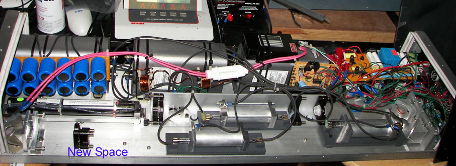
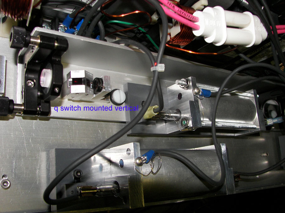
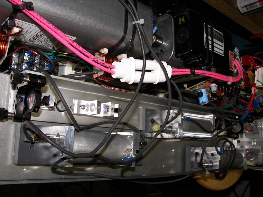
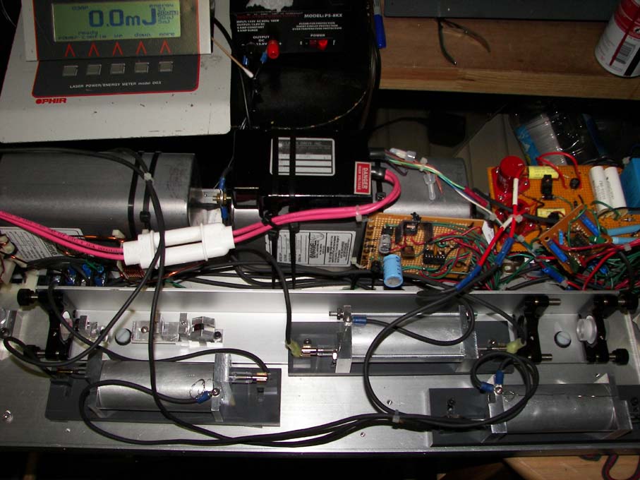
System after q switch was reoriented vertical and the amplifiers moved to make more room near the KTP. r5y1.jpg Closeup of q switch r5y2.jpg This brewster angle in the vertical plane orientation was found to create the best beam quality and brightness with the KTP crystal installed with the c axis vertical, the pencil dot pointed upward.
Version 4 had several issues. Cavity efficiencies were low in part due to cavity reflectors and this created a larger demand on pump power. This thermal load increased the thermal lensing effect, which increased the divergence of the system. This higher divergence lowered the power density of the system for conversion efficiency and 34 percent efficiency was all that was obtained. A beam reducer was tried including making more space for it, but it's optical surfaces helped to create parasitic oscillations in the amplifier chain. Obviously improved cavities could help correct some of the deficiencies noted above. Even with that the overall 1064nm output was around 250mj and was a basic limiting factor in reaching higher 532nm output as well.
The first modification to be done is to time the oscillator to the amplifiers. It was noticed during the pump pulse that the q switch pulse arrived 100 to 120usecs after the flashlamp fired. It appeared the oscillator could still be delayed 50 usecs that would allow the amplifiers to achieve a higher possible storage. So a 556-delay timer was installed to allow the oscillator flashlamp to be fired between 10 to 100usec of delay from the amplifier flashlmap firings. Optimum settings was found to be a delay of 160usec from amplifier flashlamp begin time until arrival of q switch pulse or inother words almost near the end of the flashlamp pump pulse.
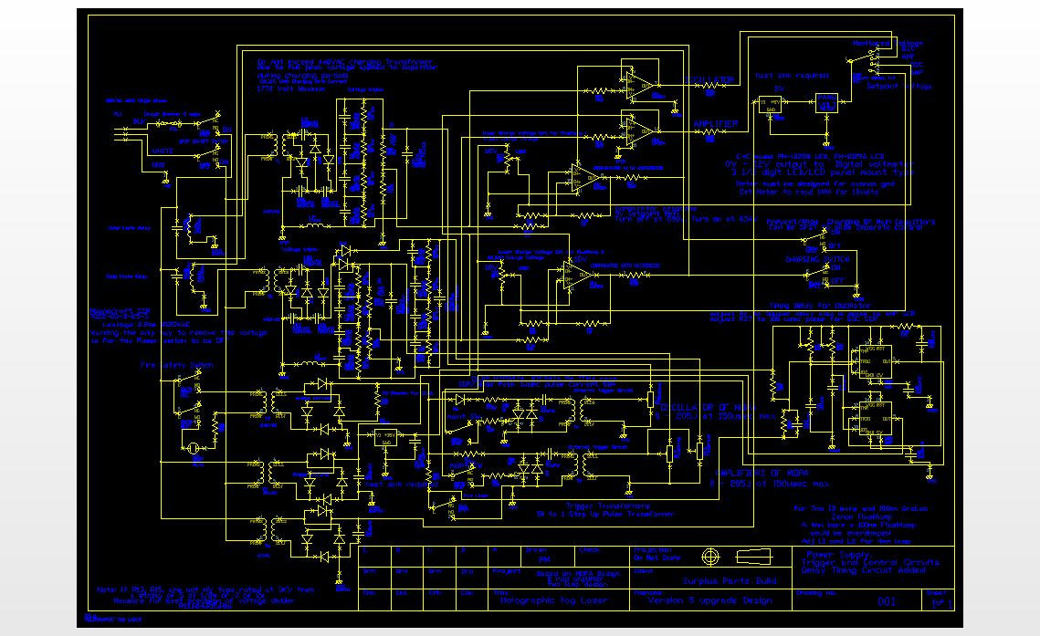
Basically the oscillator flashlamp was fired 50usec after the amplifier flashlamps were fired. With this setting the electrical pump to the amplifier could be reduced to 1200v at 132ufd from the previous 1550v. or down from 160joules to now 95joules of electrical input. Here the total system produced 220-250mj 1064nm and up to 86mj of 532nm output. Due to the reduced pump for each amplifier without loss of amplification, the total beam divergence was also reduced due to the lower thermal load. This modification was very important as it reduced the total pump power requirements to produce 250mj 1064nm and slightly improved divergence. Oscillator running at 75j electrical input was found to yield 5 to 7mj of single pulse. So before Osc 75j+160j Amp1 +160j Amp2 = 395j total pump requirement. Now the total system uses 75j+95j+95j=260j pump to achieve the same result. Here is the updated schematic with the 556 timer circuit added for delay of the oscillator flashlamp firing.yag5.dxf yag5.jpg Refer to version 1 regarding downloading a DXF viewer as this is the best way to see this schematic. A photo of the additional timer added:
Output Testing.
532nm testing indicated output polarization were at a ratio of 35 to 1 with the output polarization aligned horizontal. The KTP was mounted with the Dot marking up and the oscillator should have created P polarized vertical polarizaton due to the above mounting of the q switch crystals. But when the 1064nm was measured it appears it had almost equivalent output in both vertical and horizontal with vertical slightly ahead at a 1.27 to 1 ratio.
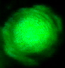
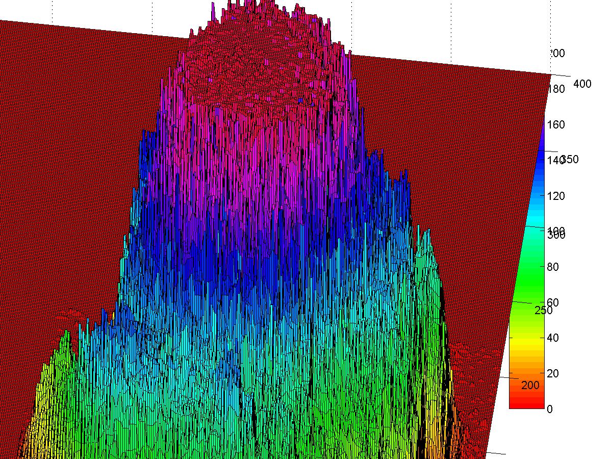
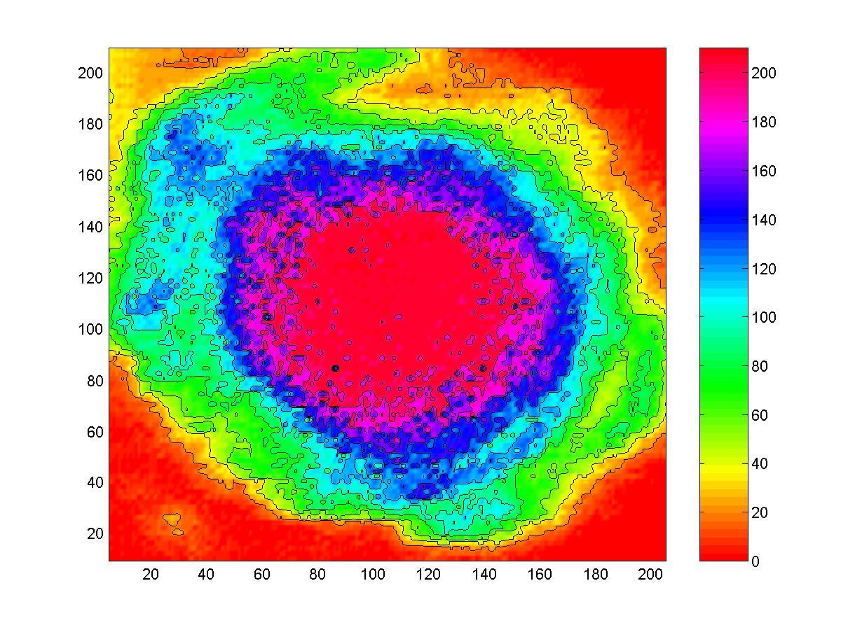
Single longitudinal mode was confirmed as the temporal envelope was completely smooth and no hint of second mode modulation on all pulses generated. Pulse width was confirmed at 10nsecs.Since SLM was confirmed and based on the observed spatial profile, the laser operated in the TEM00 mode.Images of the output beam quality with improvement due to lower beam divergence from the lower pumped amplifiers. Image: eyag1.jpg Image processing: eyag2.jpg eyag3.jpg
As it stands this laser is holographic and very capable of small film size exposures with large coherence volume available up to 6 meters. Additional improvements of conversion efficiency and additional power from another amplifier may be attempted in this version.
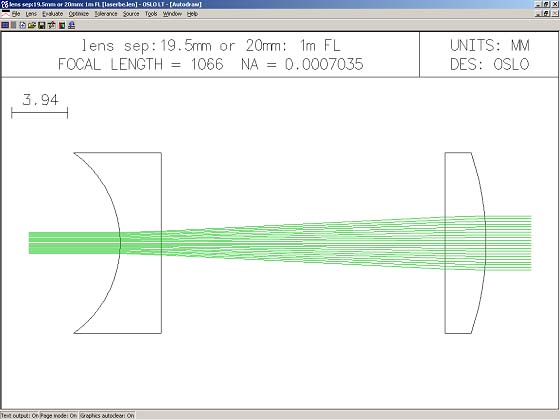
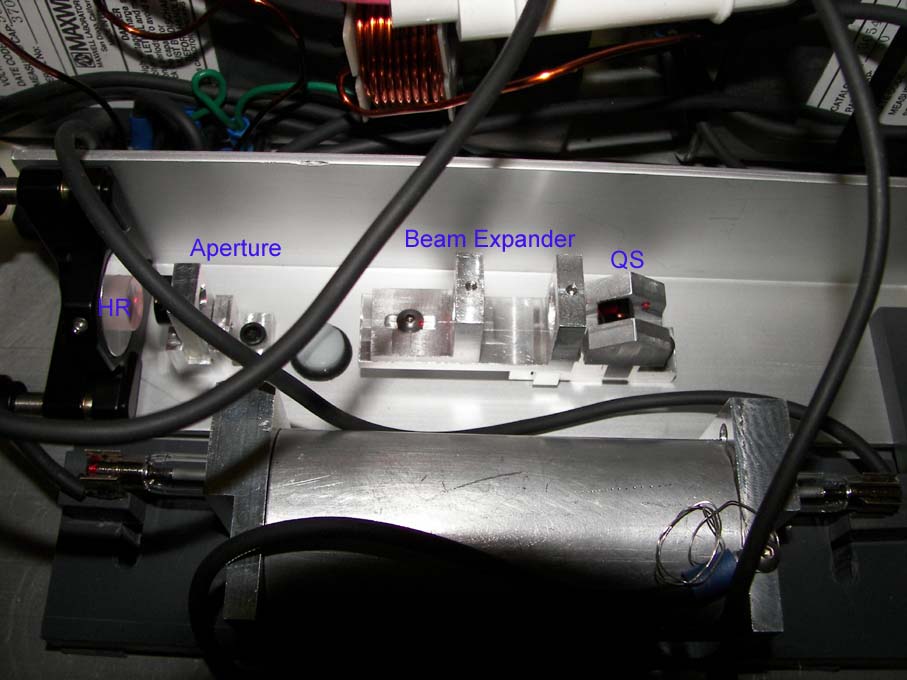
The laser oscillator upgraded to a telescopic resonator.
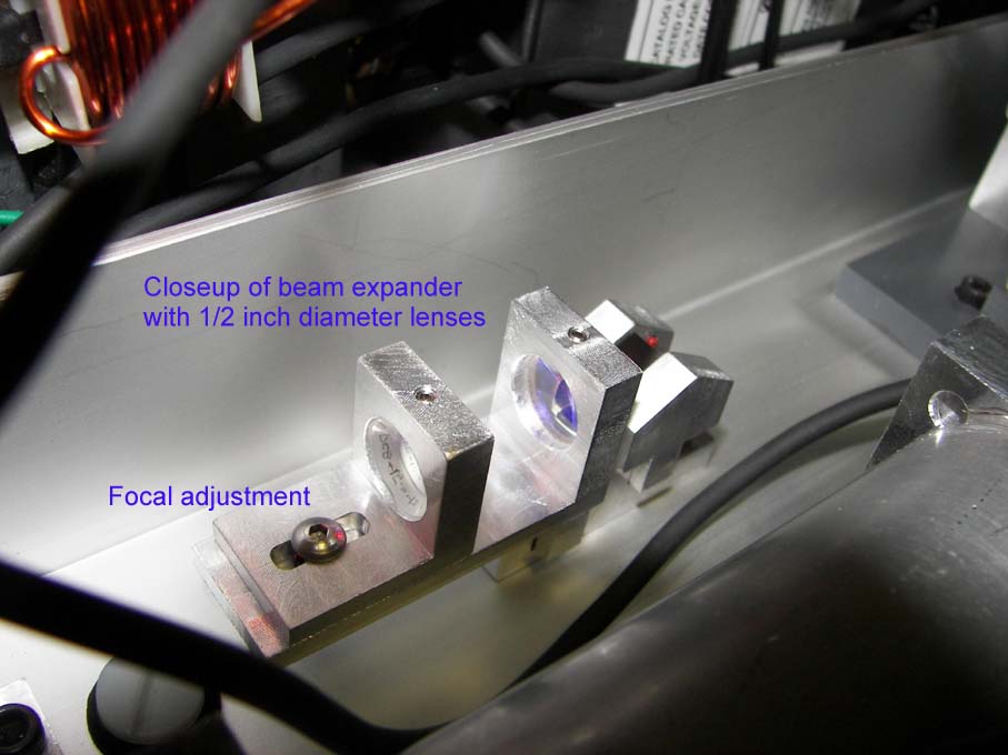
The goal is to get to 15mj of oscillator output and a beam expander will be
placed in the resonator. Two lenses from CVI laser were ordered.
PCB-12.7-7.8-C-670-1064 and PXB-12.7-19.6-C-670-1064. The first lens has a
radius of 7.8 mm and the second lens has a radius of 19.6mm. Both of these lenses
are ½ inch in diameter, 12.7mm. Both of these lenses when separated by 19.5mm
form a 2.5x beam expander to increase the mode volume in the yag rod from 1.1mm
to 2.8mm. The beam expander will be adjusted to also correct for some of the
negative thermal lensing of the laser rod by increasing to 21 mm lens
separation. lbe.jpg laserbe.len
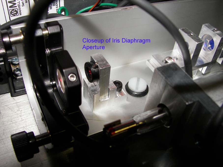
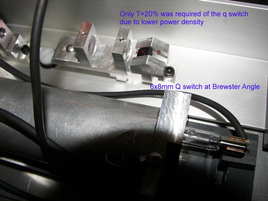
The oscillator output was increased to 9.5mj to 13mj compared to the 6 or 7mj as before but since the beam divergence was better controlled the overall 1064nm output was less at 228mj compared to the previous 275mj before the oscillator was rebuilt. A single pulse event (actually as stated before these are actually two pulses 50-100nsecs apart) was achieved with a single brewster oriented q switch Cr4+:yag crystal of initial transmission at 20 percent. This was achieved with an aperture set at 0.046 inches diameter or with a fresnel number of 0.5. With a 0.060 inch diameter aperture and a fresnel number of 0.94 for the 19 inch long resonator, the output was closer to 16 to 18mj output.
Possible future upgrade with power increase by amplifier modfications:
Method A.
Add a pre-amp to the existing configuration.
This option is designed to boost the oscillator output and reach a modest additional gain in output of the entire system. Using the additional amplification stage would double the output and if Nd:yag based create a modest power requirement on the system in terms of space and cost. Recent experiments showed that another 4 inch Nd:yag rod with a low gain input pump the same as the oscillator would increase the 5mj oscillator output to 20mj or a 4x increase. When amp 1 was run at 80joules the amplifier increased increased by 4x ,20mj. When amp 1 ran at 160j the amp output was 9x, 47mj. Amp 2 at 160j pump would boost the 47mj to 233mj or 5x. So the extrapolation would be a prepamp of 4x at 80j pump, An amp 1 at 160j pump at 7x and an amp2 at 160j pump at 3x. This would boost the 5mj signal to 420mj or 84x. At 49mw/cm2 of power density to the KTP this would increase efficiency almost to 50 percent so the output should be around 200mj 532nm. This is the more likely the upgrade path for this laser. The power supply will be upgraded to electrolytic capacitors only and a third charge circuit included for the pre-amp. By using electrolytic capacitors this will free up some space on the power side to allow the alignment laser to move other to it, then the oscillator will move down in it's place and the preamp placed in between the oscillator and the first beam steer mirror. The HeNe laser will use two gimbaled prisms to fold it toward the oscillator. It has the advantage of also being steered to the 45 degree IR mirror and this would allow it’s use on output of the laser as a setup laser.
Now that the system efficiency was improved and divergence reduced, method 1 is a very good possibility. The 6.35mm x 100mm laser rods were of limiting aperture with the high divergence before, but now it appears that another one in the chain could be used. Of course the requirement is to go to all electrolytic capacitors and the pre-amp can be ran similar to the way that the amps are ran. Both amps run from the same charging transformer and controls and is dual flashlamp fired. All was needed was for each flashlamp to have it’s own capacitor circuit and isolation diode. This same technique can be used on the oscillator circuit where the oscillator and pre-amp would run as a dual fired system system as well. So in effect two charging transformers and controls and two trigger circuits can run four flashlamp circuits.
Method B.
Replace the second amplifier stage with a larger amplifier stage.
A 15mm x 150mm Nd:glass rod would require minimum of 800 to 3500j of pump in a 250usec pulse with 3500 joules or more preferred. Because of the short pump time regarding the flashlamps this puts a strain on the flashlamp life due to explosion limit and creates a spectral shift toward blue due to the high current density cross section.
A typical lamp of 10mm bore by 6-inch length would have the following parameters: 800 joules electrical input at 250usec creates 29.6 percent of explosion limit and spectral amp density is at 4396amp/cm2, which is at the limit. Higher than this will cause too much blue shift in the spectral output due to plasma absorption and will decrease pump efficiency. So this means that multiple lamps would be needed or a helical lamp used instead. Both of these increase the lamp / power supply cost in terms of cost and complexity. Since the desire is to keep this system a small-integrated system with power and laser in one package, the power supply would require the removal of all oil caps and using exclusive electrolytic capacitors for space considerations. Another transformer and control circuit would be required along with a timing circuit for the oscillators and pre-amp. Current space limitations would allow only two lamps to be used and the gain would be modest for 1600-joule input on this amplifier. Due to KTP size, the amplifier would prove more efficient at a 3/8 inch x 6 inch amp, as a 15mm diameter amp would be under-utilized. The price of 3/8 inch x 6 rod can be almost $2k whereas surplus is a take what you can get proposition.
![]()