Home Return to Main Page
HOLOGRAPHIC YAG LASER VERSION 4
![]()
CONSTRUCTION
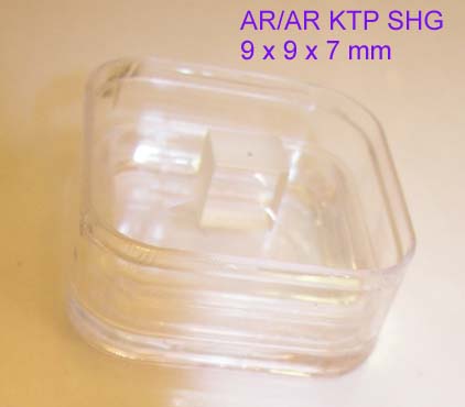
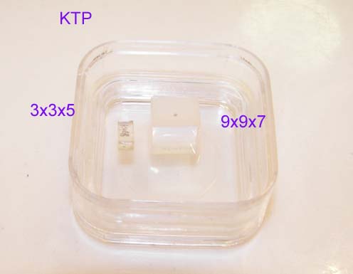
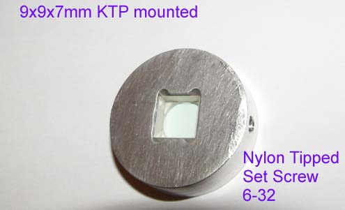
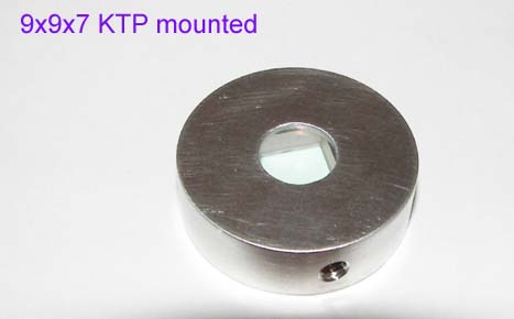
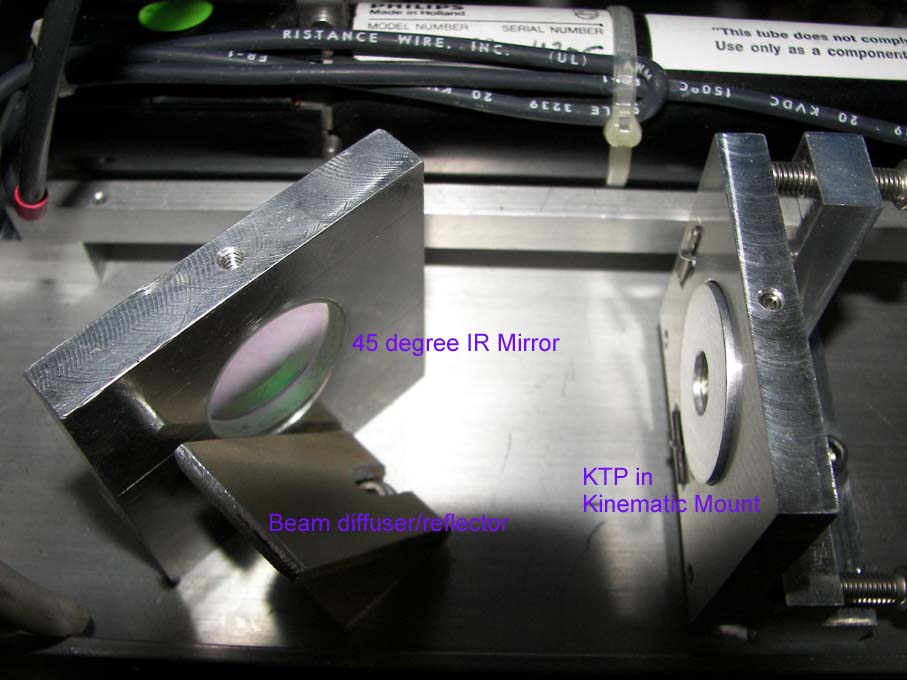
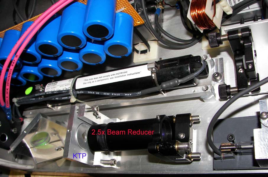
KTP TYPE II CPM SHG crystal arrived. Since KD*P has to be run so close to the AR coating damage threshold in order to get better efficiencies, it was decided an AR/AR coated 9mm by 9mm face by 7mm long KTP crystal will be tested ktp1.jpg ktp2.jpg. KTP mounted. ktpm1.jpg ktpm2.jpg. Mounted in laser ktpm3.jpg.
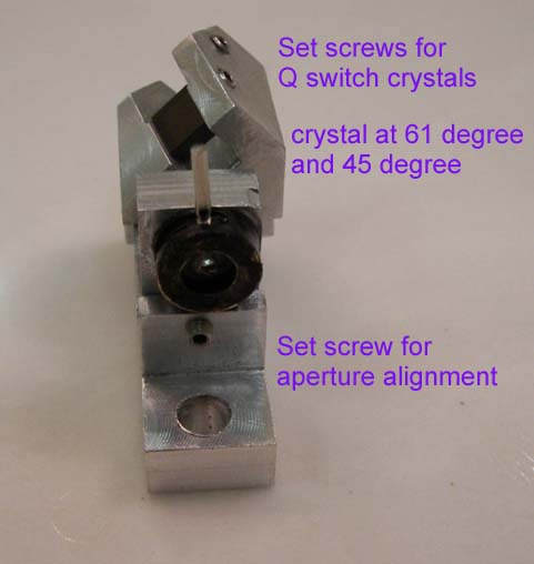
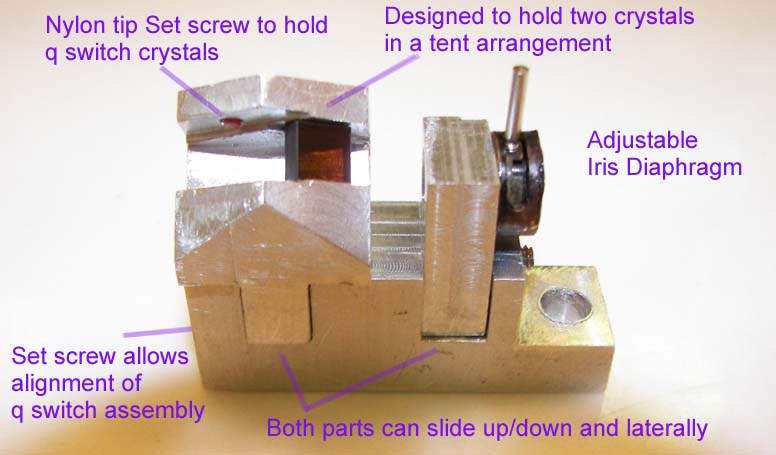
New designed q switch holder which now aligns the q switch on a 45 degree angle to provide polarization at that 45 angle for type II angle tune SHG conversion and to allow the output of the laser to become either vertical or horizontal polarized in regards to holography. In this case vertical polarized 532nm output is preferred. Two q switch crystals at the Brewster angle will help increase the resonator extinction ratio between the S and P polarized waves. Also a pair of crystals in the tent arrangement will help reduce any lateral/vertical offset of the beam. qs1.jpg Side view qs2.jpg
New 6mm x 8mm polished only Cr4+:yag crystals were ordered to allow increase in oscillator output and also to get to a single output pulse. The q switches are being incrementally upgraded to adjust T values for single pulse operation.
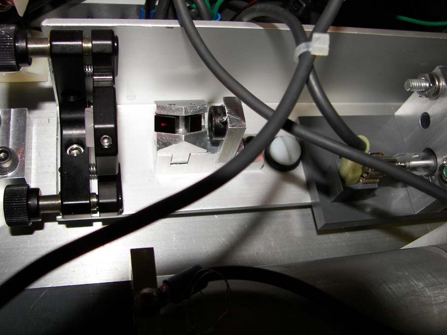
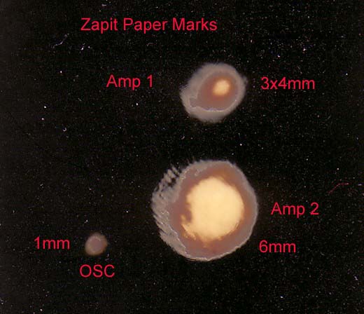
Because of the high losses caused by the q switch crystals, the Nd;yag laser was aligned without them using the HeNe laser. The oscillator was carefully aligned and then the rest of the amplifier chain and additional optics. By watching the secondary reflections while tilting the amplifiers slightly just enough for the back reflection to miss hitting the previous laser rod, prevents feedback issues and then aligning the paths through all of the centers of the rest of the optics. But once the q switches are placed back in the resonator, the oscillator is fired until the final adjustments show very good burn marks. Then a check to make sure the Zapit paper burn marks look good for each amp. A feedback check is done by turning off the oscillator and making sure the amplifiers have no parasitic oscillations by checking for any Zapit paper burn marks at the output end. The KTP angle adjusted for max output at ambient temperature. But the HeNe is no longer useful once the q switches are in, instead it can be used in a new functional role after the internal alignment was done. An upgrade will be to mount small right angle prisms for the HeNe to reflect off the final IR mirror(in effect using it as a beam splitter/combiner) and leave the laser coaxially with the pulse, bypassing it's use as an internal alignment laser and having the dual function as an external alignment laser in use in a holographic setup. Then the HeNe laser power supply will be switched off so keep the thermal load down inside the laser during normal operation. to help prevent the KTP from detuning since it is not currently being thermally stabilized.
OSCILLATOR PERFORMANCE
Single q switch output was achieved with two Cr4+:yag crystals, qs3.jpg one at T=0.2 and the other at T=0.4.
When the oscillator was run at 67 joules @1000 volts the gain was low enough that the pulse came near the end of the pump cycle. A single pulse of 2.8 to 3.5 mj was generated at an aperture of 0.046 inches or a Fresnel number of 0.76 yo1.gif . Running the oscillator higher only moved the pulse back toward the front of the pump cycle without any gain yo2.gif until it broke into two pulses yo3.gif at 135 joule input at which time 6.5 mj total was produced. 170joules produced only 6.5 to 7.1mj. Again the high pumping was losing efficiency due to the flashlamp spectral output changing as the amperes increased.
When the iris diaphragm aperture set at 0.055 inches or a Fresnel number of 1.09 the oscillator produced a single pulse of 20 nsecs and output of 4.3 to 5.1mj TEM00 mode. On closer inspection it was found to be twin peaks of 2.5mj each and 50nsecs apart. This was seen before on the earlier q switch study of using Cr4+:yag yago2.gif . This is caused by the slow relaxation time of the saturable absorber; the Cr4+:yag which is reported to be 3.4usec (ref:: Study ). Here is the oscillograms of both the aperture settings that produced TEM00 mode: a046.gif a055.gif Since both pulses are within 50nsecs of each other they will not affect the holographic use of the laser and will give results similar to a single pulse. This is not true of pulses that are separated by many micro-seconds apart since in that time frame the object being photographed can move and this movement will be displayed as interferometric fringes of what is known as double pulse holography.
Regarding the single longitudinal mode. The laser produces a very small q switch pulse but the pulse has a completely smooth and clean envelope with absolutely no other amplitude modulation. Every pulse is the same with no hint of any modulation. This demonstrates the laser always produces SLM because of the interferometer filtering configuration of the two kinematic mounted etalons, reducing power and therefore gain, and the use of a saturable absorber q switch at the lower gain which increases mode selections due the increased number of required photon round trips. Coherence length should be close to 10 meters based on calculations.
AMPLIFIER PERFORMANCE
Double Q switch MOPA output from oscillator and both amps running at 170 joules @ 1600 volts each was 244mj in TEM00 and single longitudinal mode at 1064nm. The amplifiers increased the 6.5mj oscillator output by 32x.
When the amplifiers were run at 130joules @ 1400 volts while the oscillator ran at 67joules the oscillator output of 3mj single Q switch pulse was amplified to 183mj or about 61x. Clearly the delayed pulse allowed the amplifiers to store more energy and give better gain results. Higher pumping of the amplifiers beyond 158j @ 1550 volts did not produce any more output at this delay time.
When the oscillator produced 4.5mj at the aperture of 0.055 inches and amplifier output was 230mj while the amplifiers ran at 158 joules each. Although there was an increase in total output the amplifiers only increased the input beam by 51x indicating some saturation effects.
Single pulse operation produces limited output due to the less efficient power extraction. The oscillator gain and amplifier gain beyond the time of the pulse is loss. This system when using multiple pulses over the entire pump time produced 1064nm output around 646mj. But in single pulse mode the output was at best 230mj.
SECOND HARMONIC GENERATION
Oscillator output beam size was 1mm and after first stage amp the beam size is 3x4mm and after the second amp the beam size is now 6 mm round before entering 9mm KTP hyagburn.jpg . Due to pumping the amplifier rods and the negative lensing diopter power so great, the beam is expanding too quickly for the 1/4 inch amp rods. The second amp just begins to clip the beam.
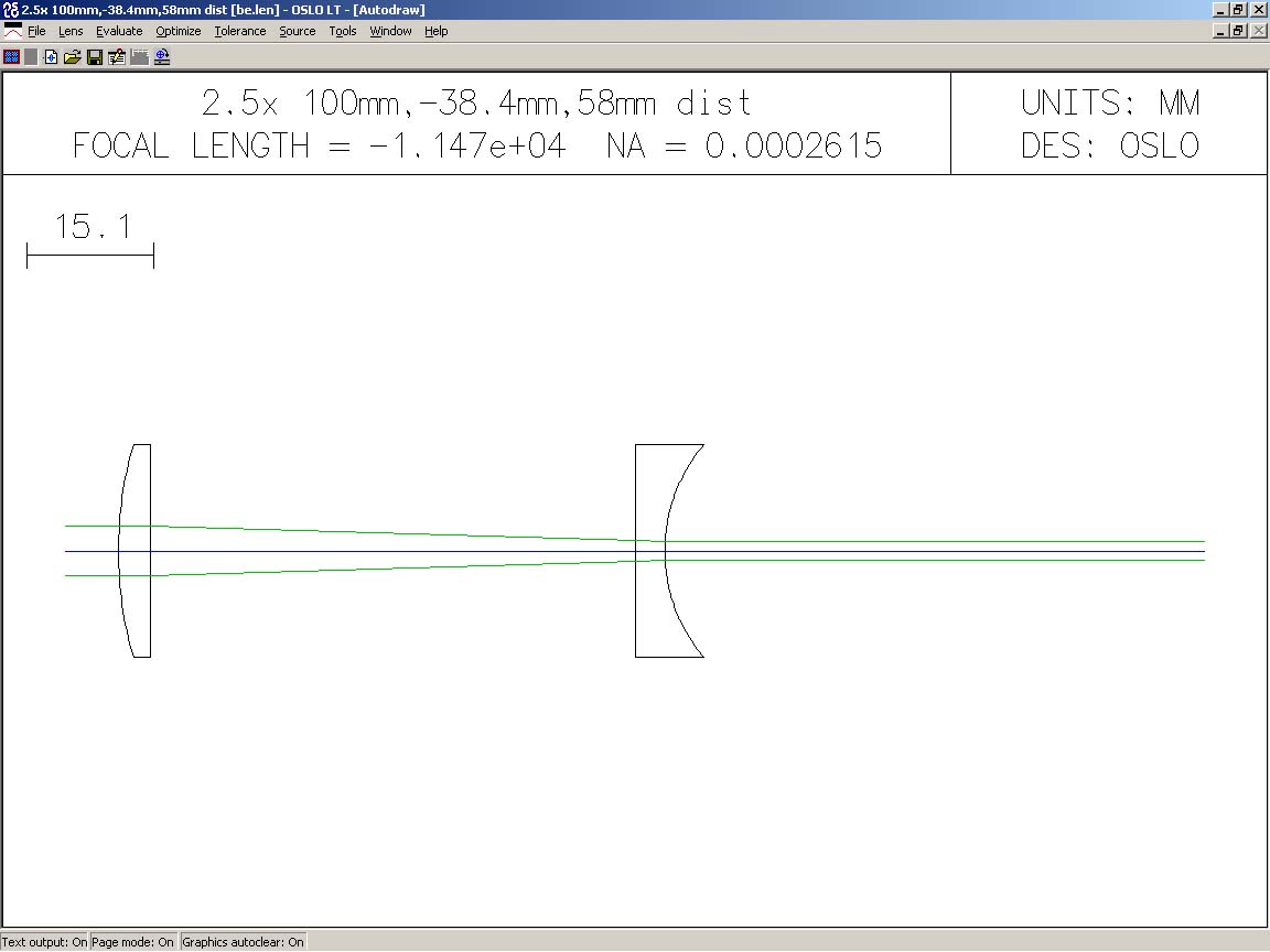
The beam size was 6mm beam at 220mj input to KTP which was at the 26MW/cm2 level. A note to remember is that since the single pulse event is actually two pulses then the conversion is based on each pulse's power density or in this case 110mj / 20nsecs/ area. The 532nm output was 68.3mj or about a 31 percent conversion efficiency at this power density. A beam reducer 2.5x was built which increased the power density of the beam to 162MW/cm2 for the above input of 220mj. ber.jpg ber2.jpg This reducer has the len’s curved surfaces oriented such that any back reflections will be expanding. Unfortunately the beam reducer was too close to the output amplifier and caused parasitic oscillations. This could not be corrected by tilt due to the proximity of the beam reducer. So this approach had to be abandoned for now.
Amplifiers ran at 158J @1550 volts:
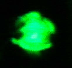
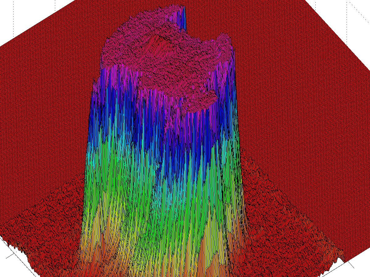
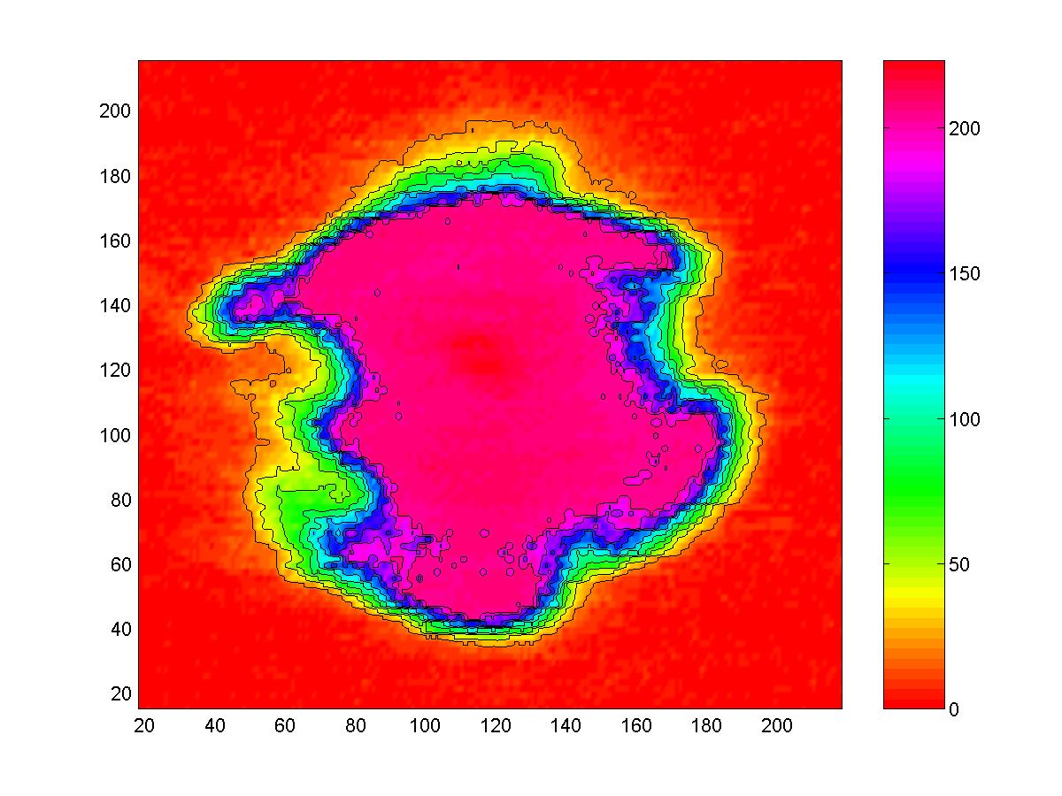
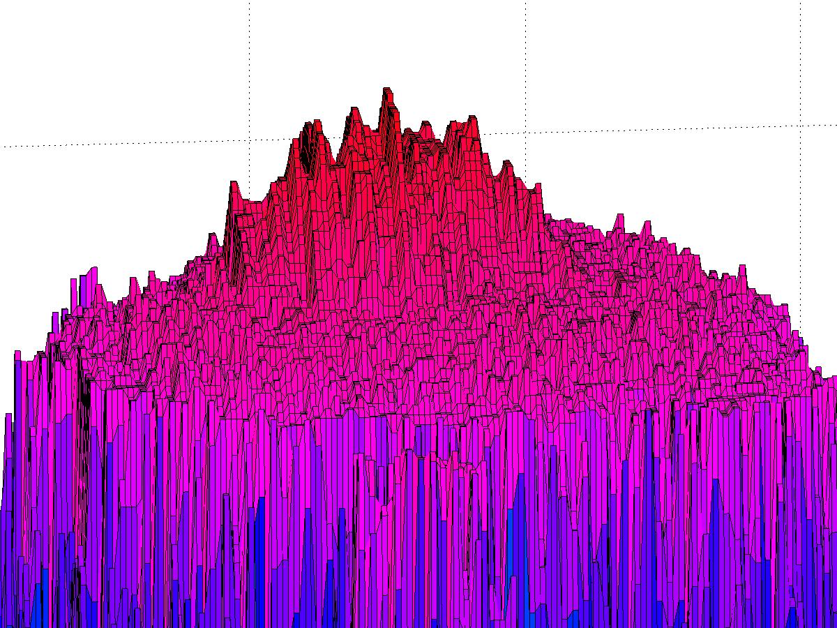
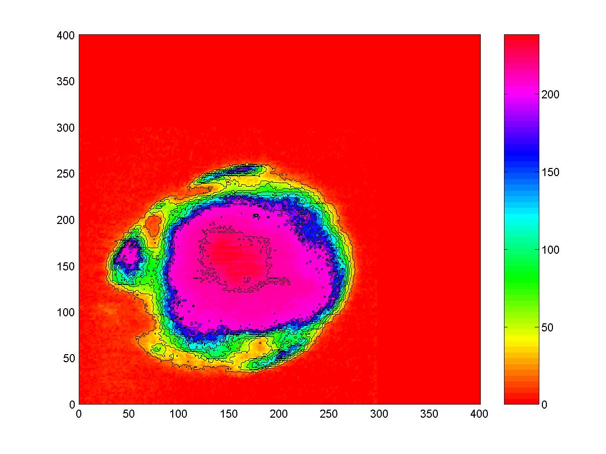
KTP oriented at 45 degrees to q switch crystals Image: spyag1.jpg Image processing: spyag2.jpg spyag3.jpg
KTP oriented parallel to q switch crystals. Image: byag1.jpg Image processing: byag2.jpg byag3.jpg
The KTP and IR mirror caused some of these side losses. Most likely due to some depolarizations in the beam profile. Notice the flat top in beam profile due to some saturation effects.
532nm polarization was sampled at the two orthogonal axis showed a 4 to 1 polarization ratio as measured when the KTP was oriented parallel with the q switch crystals. It appears that this orientation gave the best output in regards to beam quality.
![]()