Home Return to Main Page
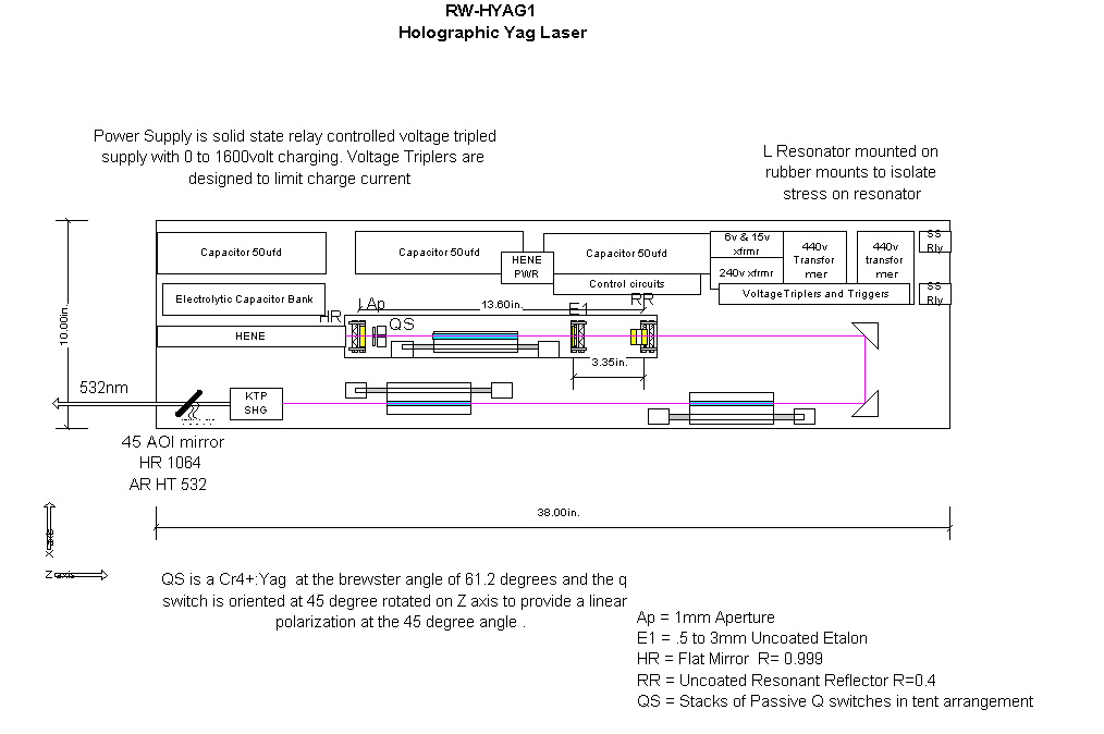
HOLOGRAPHIC YAG LASER VERSION
3
![]()
CONSTRUCTION
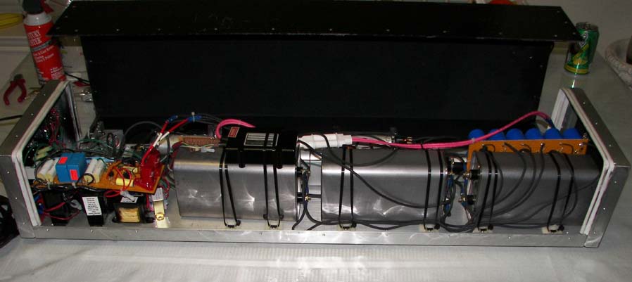
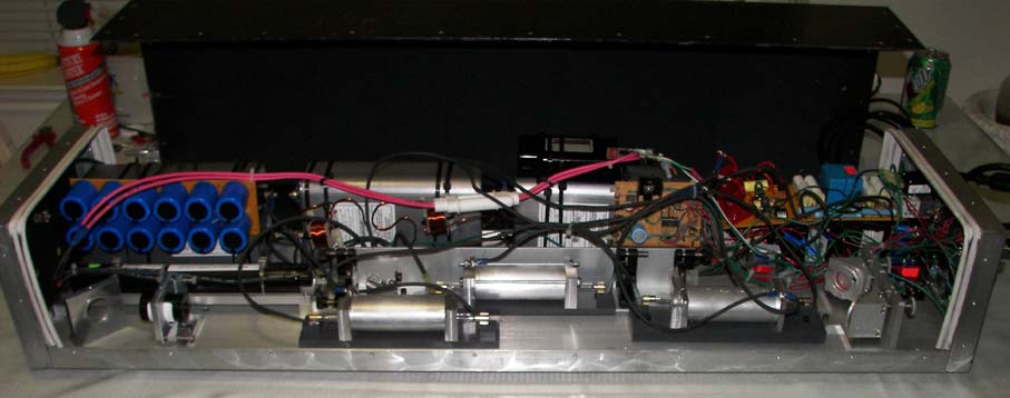
Design modified by testing: rwhyag2.jpg It is important that the amplifers stages be mounted with their flashlamps opposite of each other so that any non uniform pumping can be averaged between the two amplifers.
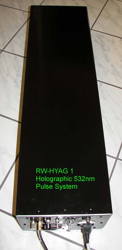
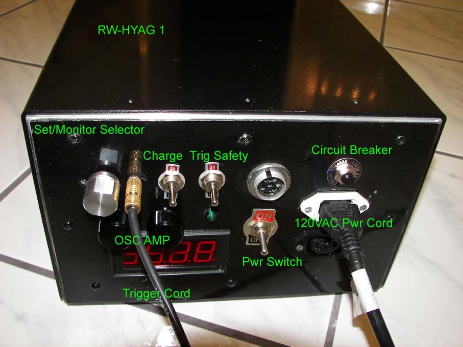
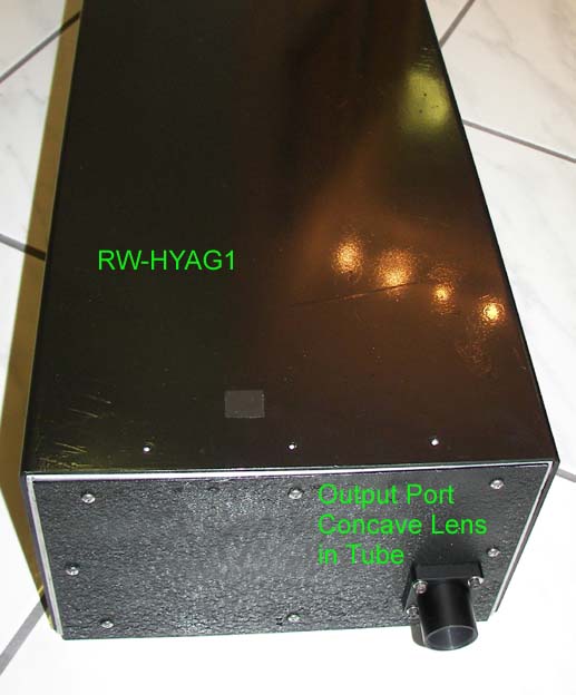
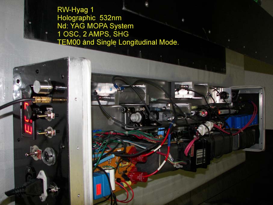
Photo of complete system: Cover on rwhyag1a.jpg One
end rwhyag1ga.jpg Another endrwhyag1h.jpg
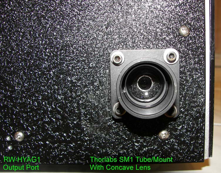
Port rwhyag1i.jpg
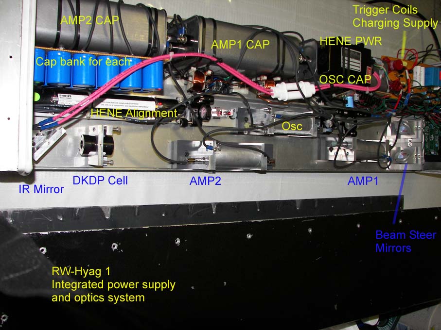
Top views rwhyag1b.jpg and rwhyag1c.jpg
Side views rwhyag1d.jpg and rwhyag1e.jpg
Bottom view rwhyag1f.jpg
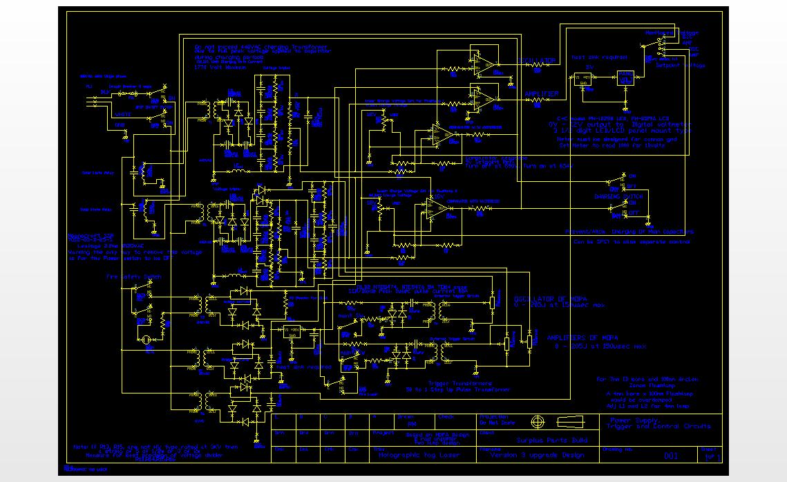
POWER SUPPLY
0 to 1770volt, 0 to 205joules per lamp, The NEW schematic: yag4.dxf yagsch4.jpg Additional spectral values can be calculated in the flashlamp section using the spreadsheet: weights.xls
OSCILLATOR PERFORMANCE
SERIES OF TEST TO FIND BEST PUMP CONFIGURATON:
Spectral output of the flashlamp design should be kept below 4000 amps/cm2 and best closer to 1700 amps/cm2 with regards to matching absorption spectrum of Nd:Yag. Here more blackbody radiation is closer to 5000 degree kelvin whereas at the higher currents it is closer to 10,000 degree (Ref: EG&G Optoelectronics). This means more radiation is in the 700 to 950nm range and a better match for Nd:Yag. In order to do this, more lamps and/or longer pulse time are needed. But longer pulse time has to be balanced against efficiency loss related to population inversion losses. So this puts a basic limit of 150usec pulse time before the Nd:Yag SE losses begin to outweigh the gain in spectral matching. For example, others have reported previously that gain efficiency is about 60% when at the pulse time is at the florescence time; 230usec for Nd:Yag. Alternately, instead of increasing pump time, a dual lamp arrangement allows a simple close couple cavity and increases the cross section area of the lamps if two separate circuits are used. Or if a series injection trigger is used then a series circuit of the two lamps doubles the impedance of the circuit and this lowers the peak current per tube cross section area.
Space considerations and capacitors directed some design issues like having to go 60usec to get critical damping for these flashlamps at the 30joule pump level but increased power requirements directs the design toward increased capacitance for longer pulse time to lower the spectral current density. Going above the spectral amps of 4600a/cm2 proved to be counterproductive as greater than this and less output was generated. Nd:Yag's absorption peaks' approximate values: 2.2 at 350nm, 2.3 at 520nm, 3.4 at 590nm, 6 at795nm, 9 at 808nm, 1.8 at 885nm. And interesting study of UV and other radiation on Nd:yag http://www.crystalresearch.com/crt/ab34/1183_a.pdf
Tests on higher gain for all the systems cavities will be based on spectral matching by reworking the pump pulse times to find the optimum point.
The first Spectral test parameters are:
Test 1: 50ufd maxwell cap at 60usec pulse
Test 2 to 8: Two maxwell 50ufd caps tied in parallel with 25uh inductor for
150usec pulse.
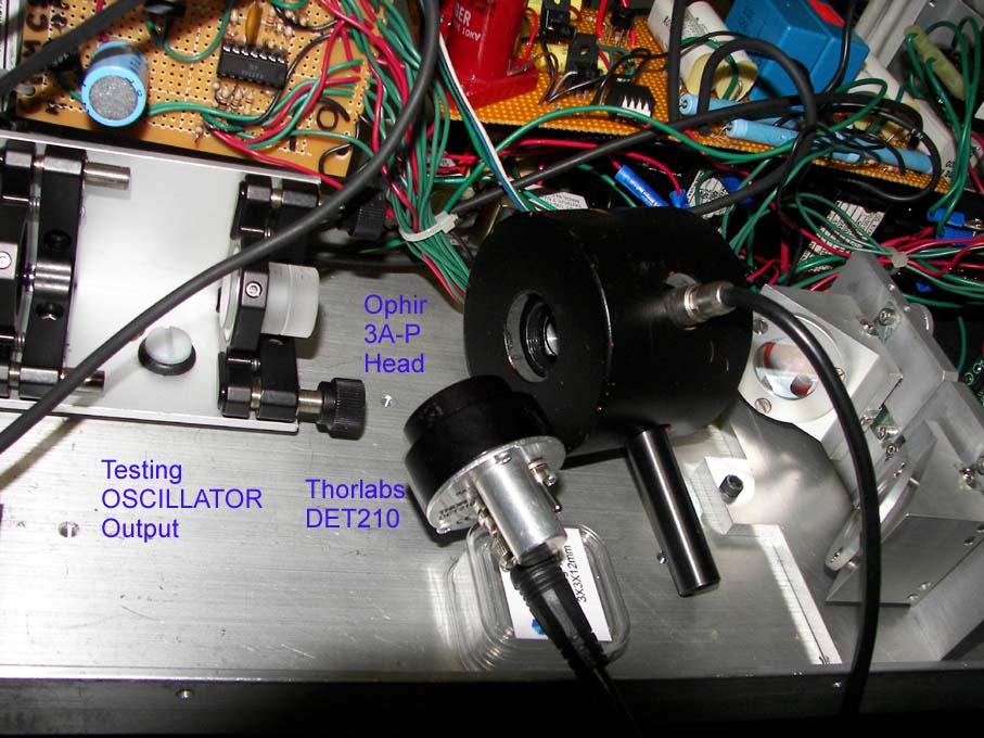
Results of Oscillator test 0.44 aperture but without q switch was:
Test1: 61j input, 1553v, damping 0.814, 18mj output, Spectral current 5565a/cm2
Test2: 45j input, 950v, damping 0.85, 19mj output, Spectral current 2397a/cm2
Test3: 50j input, 992v, damping 0.83, 26mj output, Spectral current 2527a/cm2
Test4: 60j input, 1096v, damping 0.79, 29mj output, Spectral current 2768a/cm2
Test5: 70j input, 1185v, damping 0.76, 35mj output, Spectral current 2990a/cm2
Test6: 90j input, 1349v, damping 0.72, 49mj output, Spectral current 3391a/cm2
Test7: 106j input, 1458v, damping 0.69, 52mj output, Spectral current 3680a/cm2
Test8: 133j input, 1629v, damping 0.65, 67mj output, Spectral current 4122a/cm2
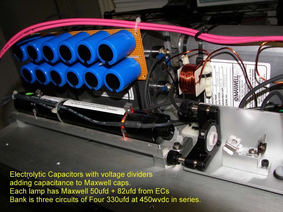
Test1 was the highest output at 60usec and 5565amp spectral with 18mj laser output which limited the electrical input to 61joules. (at 30joules 60usec the lamp was at 3900a/cm2). But once the plasma transparency was improved and the spectral shift toward red by lowering the spectral current by going to a longer pulse length and also increasing capacitance to achieve critical electrical damping for the flashlamp, we see dramatic improvement in pumping efficiency and the ability to go to much higher output. In fact the Test1 vs Test4 both at 60joule input, show that almost 2x more output was achieved due to the lowering of spectral current from 5565 to 2768 amperes/cm2. Typical q switch output would be 1/2 of the above free running values. Since available space is limited, the additional capacitance will be added to the maxwell oil caps by adding in parallel, a string of electrolytic capacitors. Therefore the power supply will be reworked, each lamp will be pumped by an additional four electrolytic capacitors of 330ufd 450volt in series. This yields a total of 50ufd maxwell cap+82ufd electrolytic cap=132ufd. Each electrolytic cap will have a 1Meg 1 watt resistor across the terminals.
Oscillator test with upgraded power supply. Added 82ufd to each 50ufd Maxwell capacitor. yagpwr5.jpg Preparing to test. test2.jpg 19.53mj total of multiple q switch pulse output from test. yago4.gif Notice more q switch pulses are created for the fixed q switch value.
AMPLIFIER PERFORMANCE
Higher gain of the amplifiers increase the divergence due to negative lensing which in most holographic cases is ok since the beam will be spread out anyway . Some correction may be needed for the SHG efficiency. Also a limit is placed on the gain of the amplifiers as too high of gain will cause greater amplified spontaneous emissions to occur which can cause feed back problems in the amplifier chain.
With 140usec pump pulse width and 120joule input the amplifier 1 output 110mj from the above 19mj oscillator output. Input into amplifier 1 was 16mj after two beam steering mirrors. Amplification was 6.9x.
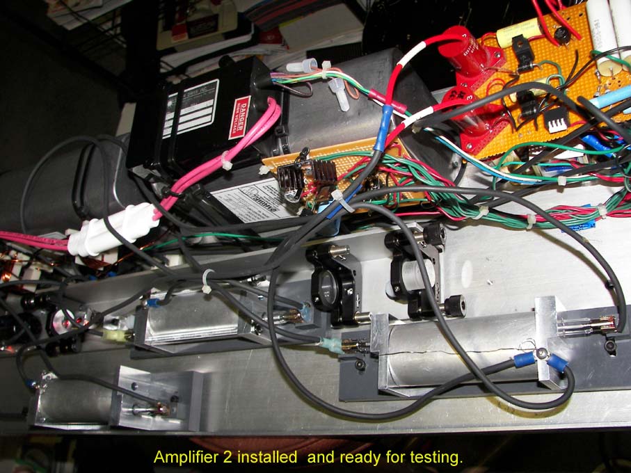
Amplifier 2 is installed. hyaga1.jpg At 120joules to each amplifier the output was 471mj. At 140joules, 488mj. Beam size was 7mm.
A test with oscillator and amplifiers at 1650 volts which is 180joules per lamp yielded a multiple q switch output of 646mj for the total system with the oscillator set at TEM00 mode 0.44 inch aperture and T=0.4 q switch.
Note of caution. The amplifiers are separated and tilted either left or right from each other to help prevent feedback by not allowing reflections to re-enter previous amp etc. Additionally the laser as indicated above will be tested at higher pump levels while watching for on set of any ASE feedback.
SECOND HARMONIC GENERATION
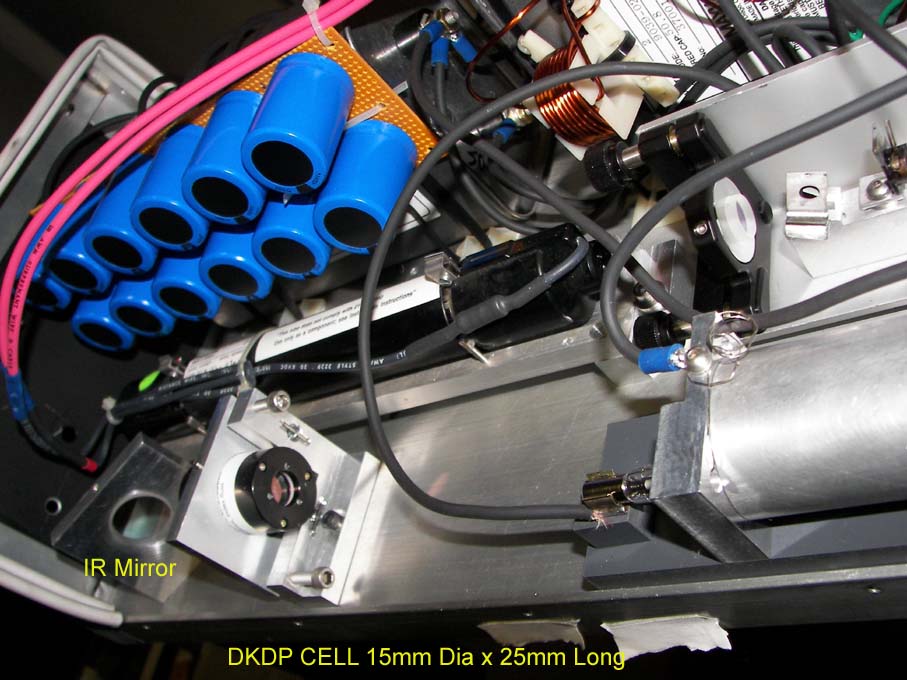
A KD*P type II phase match crystal 15mm x 25mm in index matching fluid filled cell was first tested. The general aperture-diffraction rule of 1.5 to 2 times the beam size for an aperture to reduce the effects of diffraction modulation of the spatial envelope should be kept in mind for Gaussian beams. Therefore a crystal aperture of 10mm or better is preferred. It is anticipated that up to 10nsec 600mj pulse at 6mm input would not require any further beam expansion. The SHG conversion efficiency is based on average single pulse power over the area of the beam:, calculated as: (single pulse Energy/beam area)/pulse width. Example a 10nsec 4mm 78mj pulse would be 62MW/cm2. In regards to Gaussian peak power density for damage consideration is approximated as two times this average pulse density as calculated or in this case using the above example 124MW/cm2 or 1.24J/cm2.
The parameters of energy/power density for best conversion efficiency and
under the damage threshold, can be done by the following:
Beam size control with lenses/telescopes in combination with amplifier thermal
lensing
Total output energy controlled by amplifier and oscillator output
Pulse width controlled by gain in oscillator from OC, q switch, aperture, and
pump parameters
.
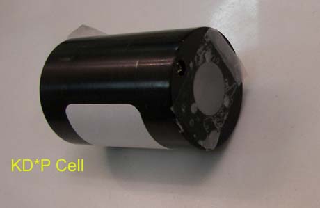
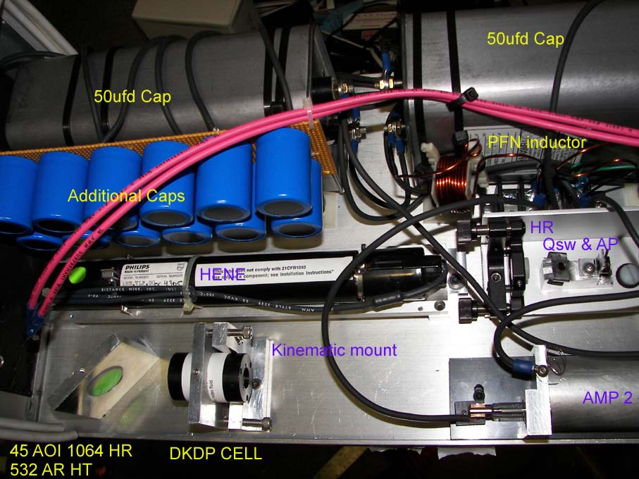
Polarization. The KD*P cell is round dkdp.jpg so the crystal was mounted at a 45 degree rotation angle for first test. Then the tent q switch mount will be re-machined to set the two q switches also in the 45 degree position so that the finished laser will have vertical polarized 532nm.
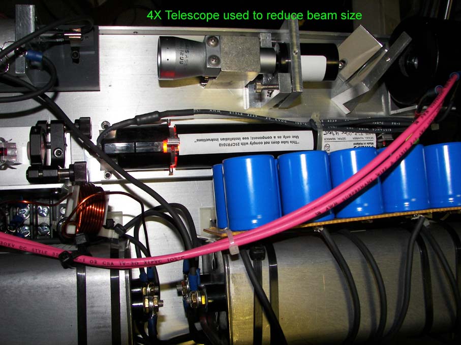
Tests with amplifier two at 496mj output, the conversion output was 137mj 532nm + 11mj 1064nm. or 27.6 percent conversion. This was achieved with a 4X beam expander used in reverse to reduce the beam size by four times be.jpg. The 7mm beam was reduced to 1.75mm. The output is currently multiple q switched pulses of about 11 pulses which means a lower per pulse energy level, with the average per pulse at 93.5MW/cm2 of power density. KTP will be tested next to give a higher efficiency and wider margin of safety for the coatings since it's efficiency peaks around 200MW/cm2. 9X9x7mm KTP was ordered for this test. Here is a research paper in gray tracking in KTP. Also interesting is they reported exit surface damage .3mm deep to KTP at 480MW/cm2 level which corresponds to a peak energy density of 9.5J/cm2. http://www.stanford.edu/group/fejer/fejerpubs/1994/72.pdf
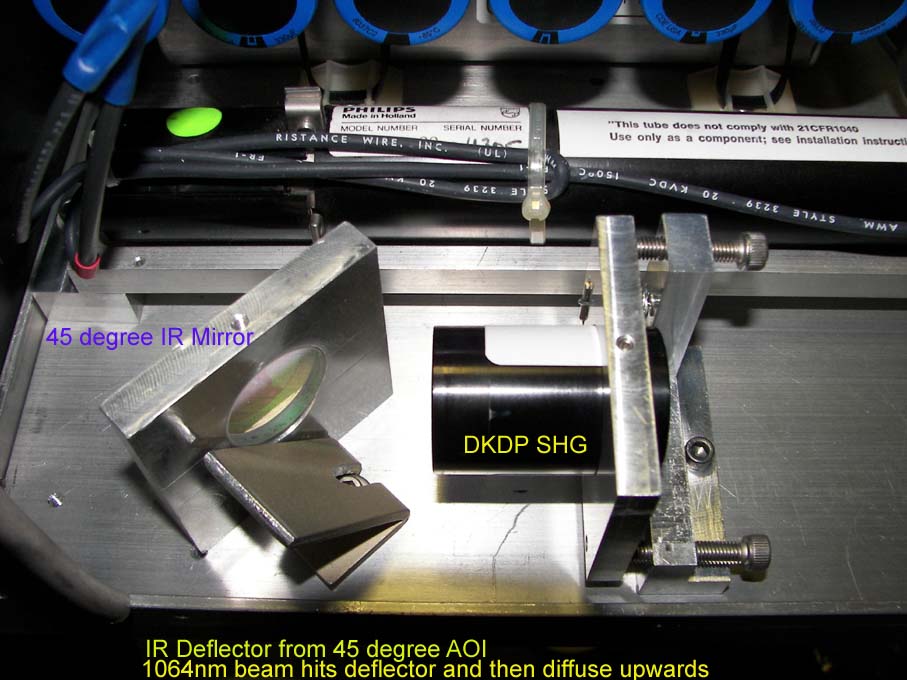
IR Filter. The filter is a 45 degree AOI HR 1064nm and AR coated HT 532 high energy mirror. Which will pass the 532nm and reflect the 1064nm to the side. Mounted on the side will be a diffuser/absorber angled so that no back reflections are sent back down the amplifier chain. dkdp2.jpg DKDP is mounted in kinematic mount and tilted x y and rotated then held by set screw. dkdp3.jpg A test of the IR filter showed 10.77mj leakage from a 531mj incidence on the mirror which indicates 2 percent leakage or 98% of the IR would be filtered. Since it is anticipated at least 50 percent of the IR will be converted to a second harmonic, it is anticipated that the laser would leak even less at full power.
Angled diffuser mounted to diffuse IR coming from the 45 degree IR mirror irfilter.jpg
![]()