Home Return to Main Page
HOLOGRAPHIC YAG LASER VERSION
2
![]()
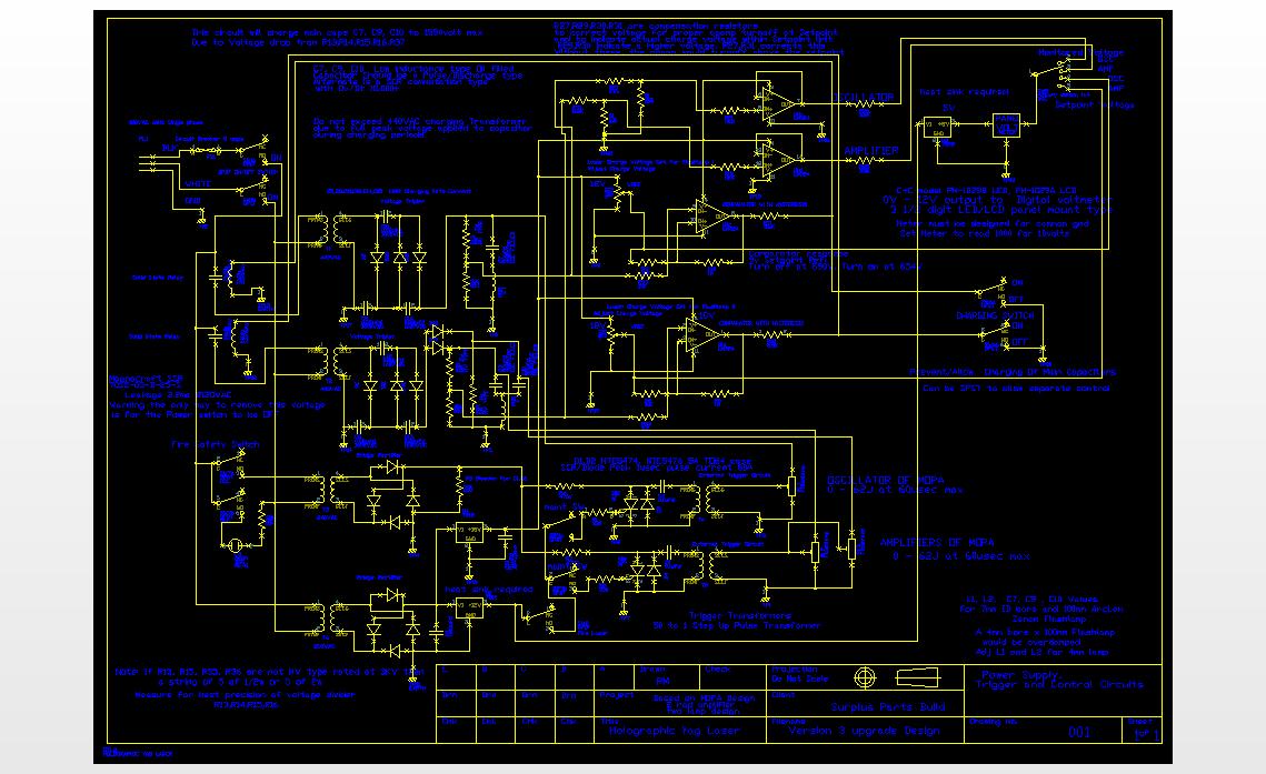
POWER SUPPLY
After initial tests, the power supply was upgraded by using a voltage tripler to prevent the need to replace transformers. The oscillator and amplifiers uses a 50ufd 2kv caps and at 1549 volts would up to 60 joules for each Nd:yag cavity. Power supply schematic: yag3.dxf
yagsch3.jpg JPEG of the schematic but better to use dxf viewer as you can zoom/pan etc for better detail.
Free dxf viewer from Solid works: http://www.solidworks.com/pages/products/DWGgateway/eDrawings-Free3Dand2DCADViewerandPublisher.html
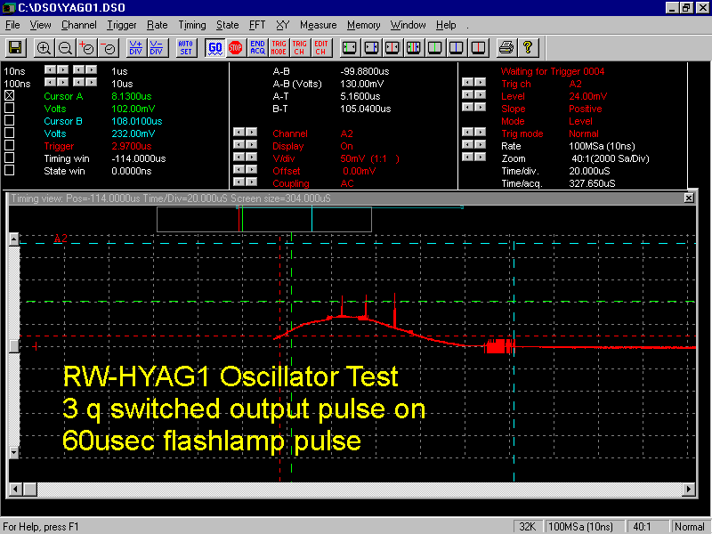
OSCILLATOR PERFORMANCE.
SECOND TEST:
Output energy. yago1.gif yago2.gif at a voltage of 1488volts and 55 joule input, the laser oscillator produced 6.8mj of q switched TEM00 output. This test indicated that modifications would be needed to achieve a higher gain and output.
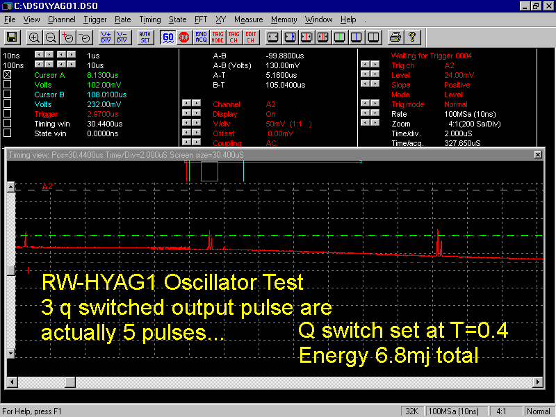
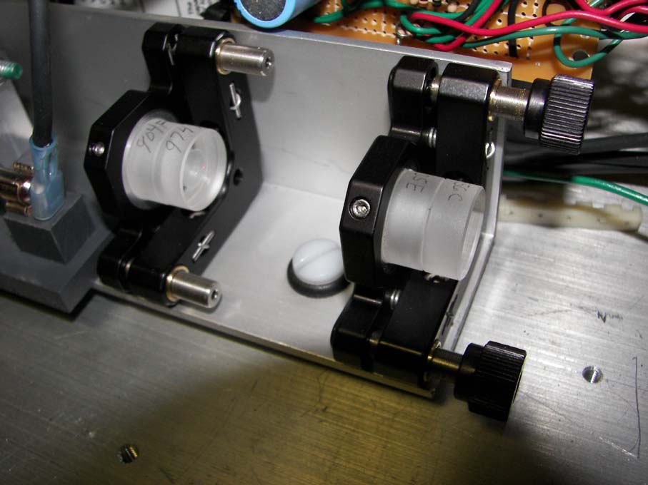
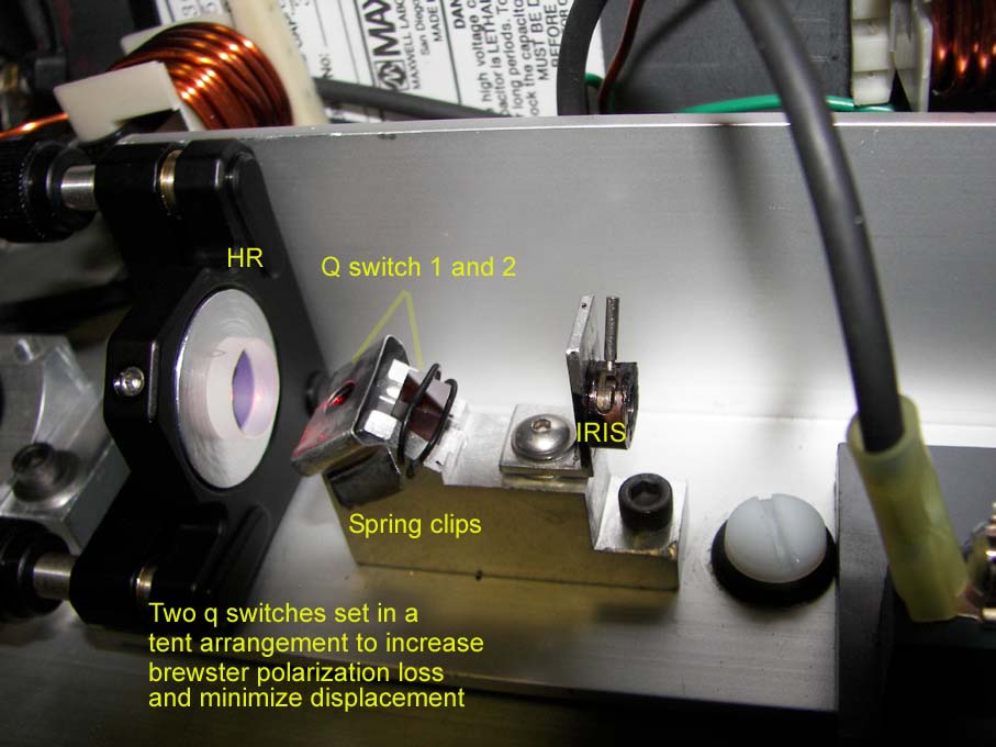
Q switch output. As a starting point a single polished only (no AR coating) 5.5mm x 5.5mm Cr4+:yag q switch with T=0.4 will be used at the Brewster angle of 61.2 degrees. The design is to add multiple q switches which increase polarization extinction and reduce initial transmission to allow higher q switch energy.
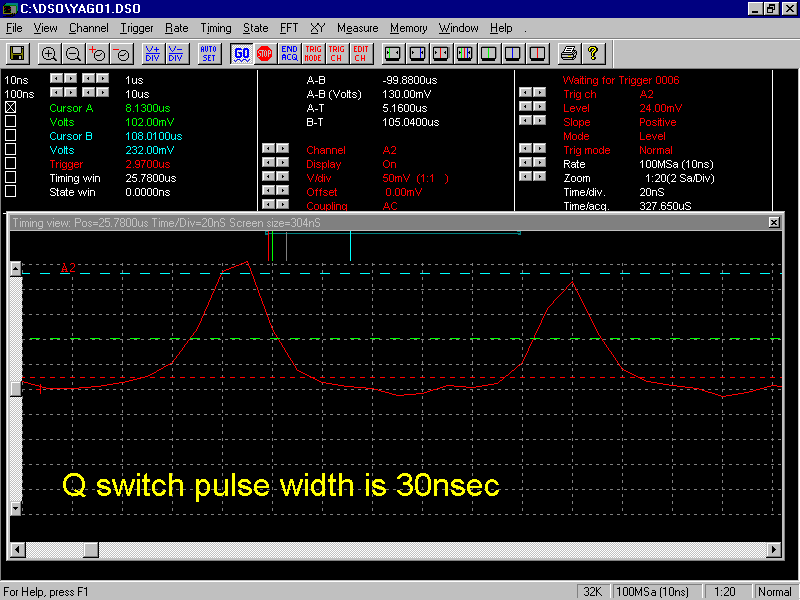
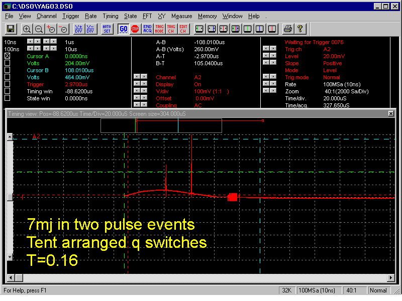
Output pulse width. yago3.gif Output pulse width was 30 nanoseconds. With a single T=0.4 q switch, multiple pulses were observed for the 6.8 to 7.5mj output. These pulses basically were 2mj each. At 1166volts and 34 joules of input, a single q switch pulse of 2mj was observed. When two T=0.4 q switches were used and at the 1488volts and 55 joule input produced two pulses of 7mj total output which had 15 to 20 nanoseconds of pulse width.
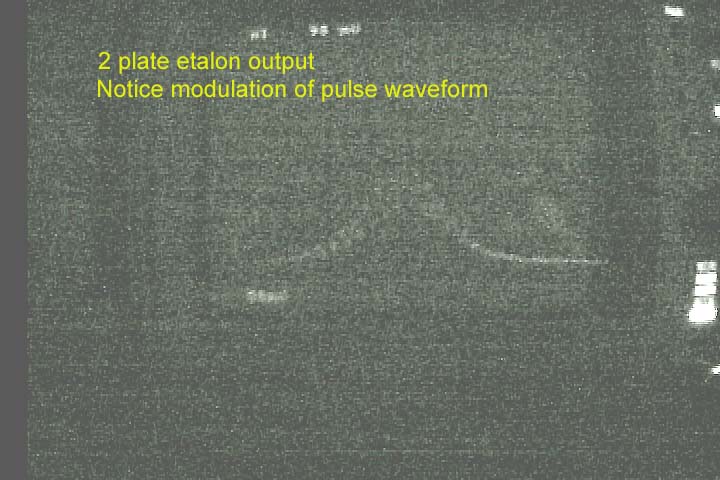
Longitudinal mode behavior observed. With just the two plate etalon, hyagl3.jpg up to full modulation of the temporal pulse
width was observed with a TEK2465B analog 400mhz oscilloscope. Modulation
displayed as a clean smooth periodic sine type, suggests the laser was
producing only a few longitudinal modes. Some shots had more modes based on
more ragged random modulations. This suggest the laser's coherence length was
around 20 inches with the two plate etalon. Very fast analog scopes are good at
observing the temporal modulations. Very sharp ragged modulations on the pulse
envelopes have been documented in research papers to show that coherence length
drops down to 1 or 2cm. Typical digital scopes due to Nyquist limitations will
not present this information which can be in the hundreds picosecond regime.
Compare yago3.gif from a 100 million sample/sec DSO
(10nsec resolution) and hyagl3.jpg. from the above
analog scope with a 1.337nsec resolution . The modulations seen on the analog
are about 3ns periods on the 30ns pulse whereas on the DSO only 10ns can be
resolved and the modulation information is lost. The
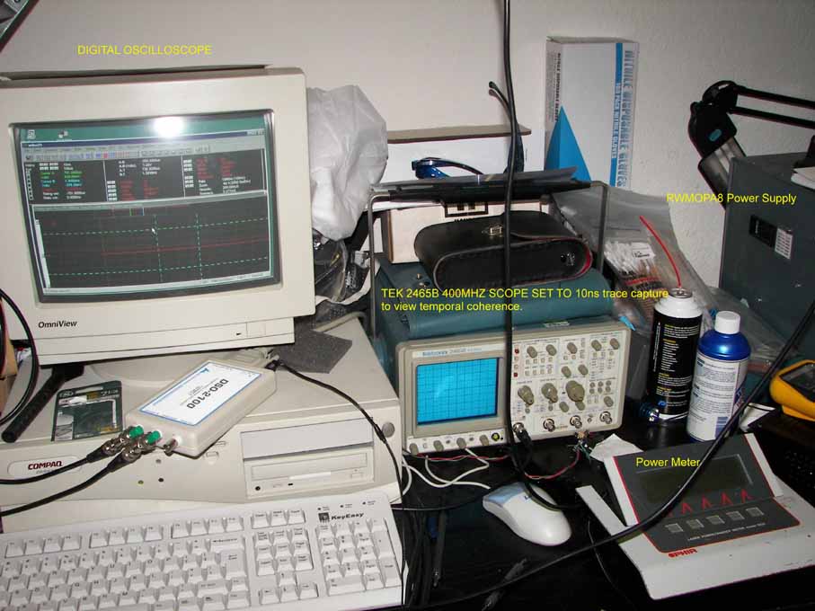
test setup test.jpg used
was a Tektronix 2465B a 400 MHz analog scope 0.875 nsec rise time set at 50ohm
impedance with Thorlabs DET210 detector with a 1ns rise time. In order to get a
general idea of what the total composite rise time of the measuring equipment,
it was calculated as follows: 0.875nsec for the scope, 0.011nsec for each bnc
connector, 0.15nsec for the RG58 10ft cable, and 1nsec for the detector for a
total system rise time = 1.337nsec = sqrt(0.875^2+0.011^2+0.011^2+0.15^2+1^2)
or in this case 4 nanosec pulses would look like 4.2nsec pulses.
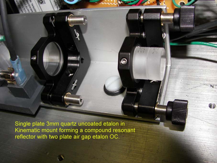
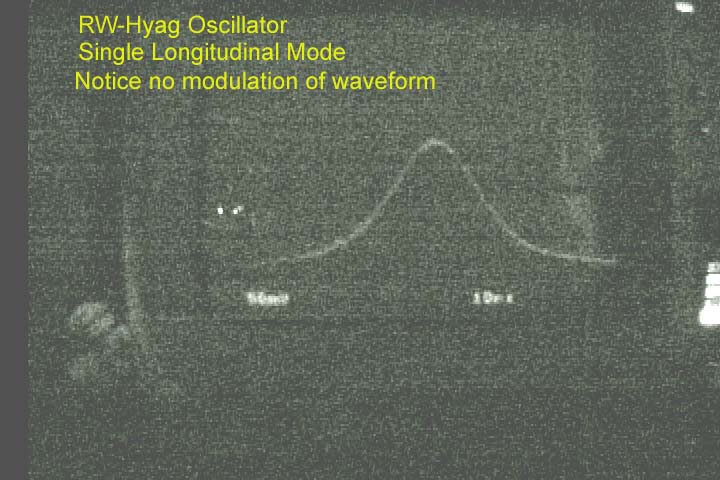
etalon3.jpg With a single plate etalon mounted in the third kinematic mount and aligned to form another Fabry Perot resonator, the laser achieved single longitudinal mode more than 80 percent of the time and only occasional 2nd mode developed but no more than 20 percent modulation suggesting the second mode was much weaker and not a major contributing mode. In essence the laser now operates as a TEM00 single longitudinal mode hyagl4.jpg This would suggest a coherence length in meters. Here is the oscillator with two of the two plate etalons used for testing. This configuration also was single longitudinal mode. etalon4.jpg
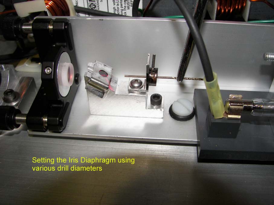
Spatial mode. iris.jpg 0.42 to 0.44 inch setting on iris diaphragm helped to assure TEM00 mode. Fresnel number was 0.67 Zapit Burn marks indicated nice round smooth Gaussian like pattern with no noticeable depolarization loss. The small diameter of the beam helped in this regard. Once single longitudinal mode is confirmed then the spatial mode is also checked at the same time. If TEM00 mode is observed at the same time then it can be assured to only contain this mode. Else multi mode axial modes can allow multi mode TEMs. The power in the bucket test or the M2 test can be performed to verify the degree of TEM00 mode to the other possible low order TEM modes in multi longitudinal mode output. The older and not as accurate “power in the bucket” test is based on an energy meter at a measured distance using the hyperbolic propagation function and the resonator's calculated beam waist at OC with an aperture in front of the meter head to measure the power difference with and without the aperture. Gaussian beam have predictable power loss based on a given aperture size and additional TEM modes will be partially lost from the energy measurement.
To align the laser. Open iris. Place card after the OC. Observe card while
adjusting
To obtain good spatial quality and maximum effect, the two kinematic mounted etalons must be adjusted accurately to each other and the HR. Zapit paper was used to fine tune the two etalons to each other. By observing the burn pattern and adjusting the single etalon additional burn marks can be brought to overlap with the main HR and two plate etalon burn pattern. The use of multiple plate resonant reflectors requires careful alignments of the individual kinematic mounts if good spatial beam quality is to be maintained.
Polarity. Two orthogonal axis was measured as 4.32mj and 0.69mj with these axis not precisely aligned with the actual polarized output. These numbers suggest a polarization efficiency ratio of at least 85% due to the use of two Brewster angled q switches. Two T=0.4 q switches are used in a tent arrangement to provide a higher degree of linear polarization by increasing the extinction ratio per pass. The tent configuration minimizes the lateral offset of the beam caused by the Brewster angle. tent.jpg tent.gif
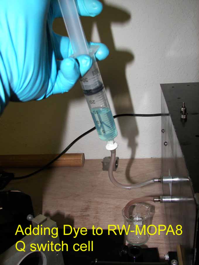
Q switches will be upgraded to a lower transmission values in order to get to a single pulse. As output power is increased an increase in absorption is needed to reduce the number of q switch pulses. Liquid dye q switches easily allow an increase in dye concentration, but for crystals they only work in a very limited range. Here is an example of a specific dye concentration in ethanol being added to a holographic ruby laser dyecell.jpg a fixed value crystal does have the advantage of not needing maintenance. The above detailed yag oscillator created a single 2mj pulse at T=0.4, 3.5mj at T=0.16. Additional values of initial transmission are being investigated as T=0.1 and T=0.04 (96% initial absorption).
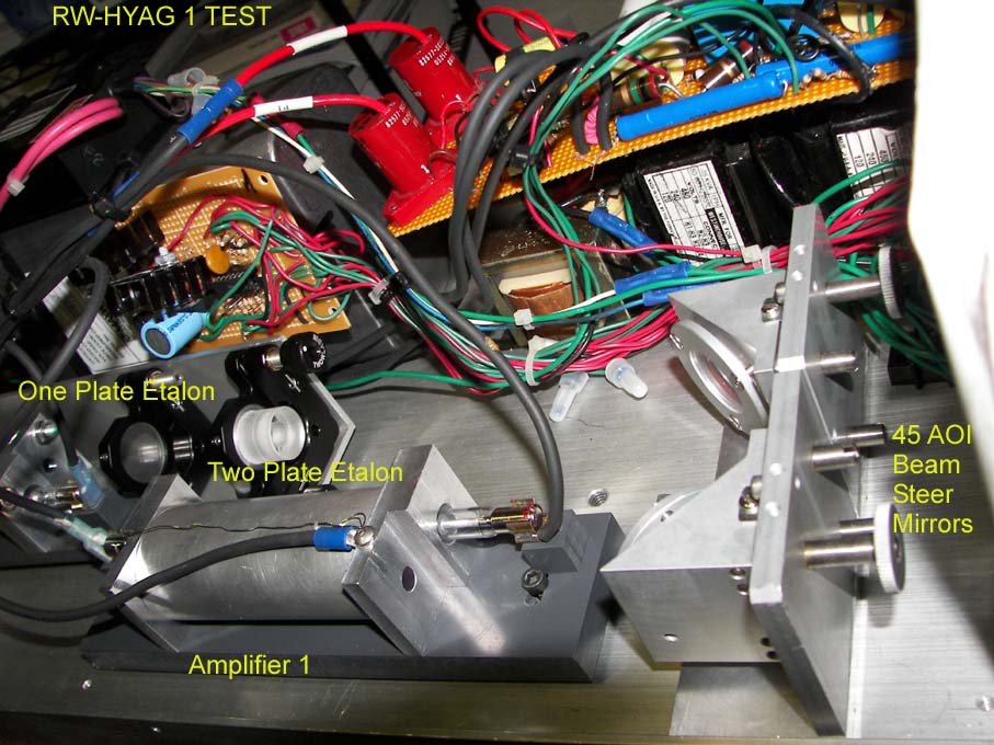
The amplifier is hard mounted on PVC plate to provide electrical isolation to the cavity since it also is charged to 10kv during the flashlamp triggering. The anode and cathodes of the flashlamp are also insulated mounted. hyamp1.jpg The amplifiers is built similar to the oscillator. 6.35mm x 100mm Nd:yag rod with a single 7mm ID bore x 100mm arc length flashlamp.
Beam expander optics. Normally necessary to keep the output energy level below the 10 joule per centimeter squared level to prevent rod end/coating damage. But due to optical pumping of the yag rods that creates a negative lensing, the passing beam expanded. Oscillator beam output was 1mm, but due the negative lensing effect amplifier 1, the beam expanded to 3mm. It is anticipated that amplifier 2 will expand the beam further to between 5 to 6mm before SHG crystal. So it appears that the beam expanders may not be needed with regard to energy level.
Beam quality looks good at the output of amplifier 1. The 7mj pulses were amplified by amplifier stage 1 to 39mj which is a 5x increase with 60joule input.
![]()