All Rights Reserved
Reproduction of this document in whole or in part is permitted if both of the following conditions are satisfied:
1. This notice is included in its entirety at the beginning.
2. There is no charge except to cover the costs of copying.
DISCLAIMER
UBPD1 is intended for use in hobbyist, experimental, research, and other applications where a bug in the hardware, firmware, or software, will not have a significant impact on the future of the Universe or anything else. While every effort has been made to avoid this possibility, UBPD1 is an on-going development effort. We will not be responsible for any consequences of such bugs resulting in material of financial loss. or bruising to your pet's ego from any number of causes directly or indirectly related to this material. ;-)Acknowledgment
Thanks to Jan Beck for getting me interested in microcomputer development. If anyone had told me six months ago that I'd be writing code for an Arduino-compatible board - and enjoying it (sort of) - I would have suggested they were certifiably nuts. ;-)Introduction
UBPD1 is a simple microprocessor-based controller for driving loads like servo motors and electromagnet coils. With a 5 ohm load and 16 VDC power supply, its continuous range via a knob on the front panel is from approximately -2.75 amps to +2.75 amps. For other loads and power input, the range can approach ±4 amps. A 2 line LCD provides real-time status for current, percent drive, and other optional parameters.
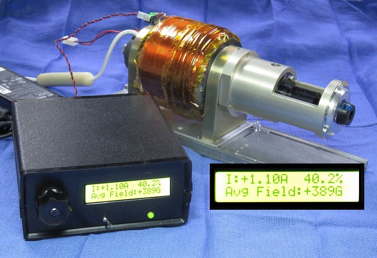
UBPD1 installed in Cheezy Plastic Box with Zeeman Electromagnet. ;-)
If you are curious, the photo shows UBPD1 driving a biased electromagnet used to evaluate and test Helium-Neon laser tubes using the Zeeman effect to generate a pair of optical frequencies up to a few MHz apart. For this application, tube design and magnetic field are critical in determining the outcome. More on this may be found in the section The original Application. For the purposes of constructing UBPD1, what matters is load and maximum current.
UBPD1 uses a rotary encoder for control with a 2x16 line LCD (HD44780 standard) display for the current and Gauss readouts. The knob specifies a current from around -2.75 to +2.75 A. It is implemented open-loop so scale factors for the current field is stored in the firmware. Eventually, current feedback using a 0.1 ohm sense resistor may be added to maintain the set current closed loop even if the coil resistance changes due to temperature. Then, when the encoder knob is turned, the controller would incrementally adjust the current from its previous value based on a moving average of the sensed current. When the knob is stationary, it will maintain the current at its present value by adjusting the PWM. The average field strength will be calculated using the sensed current based on the above data (or more likely simply the slope based on the end-points). However, I rather think adding this to the prototype is unlikely as it works well enough as-is.
UBPD1 also would make an excellent educational project for basic electronics and Arduino programming. The modules and electronic components are all readily available and very inexpensive. The entire cost using parts from eBay and electronics distributors like Jameco or Marlin P. Jones is well under $20. Modifications or enhancements can be easily done once the basic system works.
Specifications for full range Zeeman magnet coil driver
These apply to the prototype built for the original laser application. More info on this below if interested. But that's why it has the magnetic filed in the specs: ±2.75 A into the coil changes the field by around ±350 Gauss relative to the permament magnet's value of 268G.
- Magnetic field range: Approximately -100 G to +600 G (where the sign indicates the polarity with respect to the standard HP magnet).
- Current range: -2.75 A to +2.75 A.
- Display: 2 line x 16 character backlit LCD:
   Line 1: I: ±X.XXA YYY.Y%
   Line 2: Avg Field: ±ZZZG
- Indicator: Red/green bicolor LED monitoring drive to coil.
- Power input: 16 VDC, 4 A power pack.
- Controls Main power (toggle swith for 16 VDC), Rotary encoder (knob) for Current/Gauss, Enable switch (Atmega input) to turn on PWM.
- Physical: Case similar to that of small HeNe lab supply with plug-in laptop-style 16 VDC power pack.
Wiring Diagram and Parts List
The Atmega firmware is called "Zeemagnet Driver" since the original intended application was to control the field for a Zeeman laser. :-) This runs totally open-loop using the encoder knob alone to adjust the current. The major components the Atmega 328 Nano 3.0, H-bridge driver PCB, and 2x16 character LCD. The driver PCB has the L298, free-wheeling diodes, and a 78M05, 5 V regulator. (For this setup, it is disabled as recommended where the input voltage is above 15 VDC, and a separate 7805 is used.) The two channels of the L298 are driven in parallel. An encoder is specified since it was desirable for the default current at power-on to be 0 A regardless of knob position. The sense resistor is present but not used just to assure that its voltage drop won't affect operation since the return current of the L298 also passes through it since its in the total return current path from the -Bridge driver PCB and thus will add a small offset to the logic levels. A small fan was also added blowing air through the L298 heat-sink.
The major parts are listed below. This doesn't include wire, solder, etc.
- Atmega 328 Nano 3.0.
- L298 H-bridge driver PCB.
- HD44780-based 2 line x 16 character LCD.
- Rotary encoder with knob. (Potentiometer with knob is an alternative.) If it is a TTL-compatible optical encoder, debouncing is probably not needed. But if it is simply a rotary switch-type, software or hardware debouncing will probably be required.
- 16 VDC 4 A power pack. Since the actual current will depend on the input voltage, it's critical that the power pack be regulated. But it can be a voltage other than 16 VDC. Just adjust the current calibration. 16 VDC was selected for the prototype because (1) with a reverse polarity protection diode, the result would be close to 15 VDC and (2) because they were available. :) For more precision, a higher input voltage and suitable high current regulator could be used to drop the voltage.
- DC power connector to mate with power pack.
- Prototype perforated board 5x7 cm (or whatever size you prefer).
- 30 pin 0.6 inch DIP leaf spring socket for Atmega. Note: Machine pin sockets are not suitable to accommodate the 0.04 inch posts generally provided with the Atmega board.
- 7805 5 V regulator IC, 2x22 µF filter capacitors. A small heat-sink for the 7805 won't hurt.
- Red and green LEDs or combined 2 pin red/green LED, 1K ohm series resistor.
- 10K ohm trim-pot for the LCD contrast control.
- 3x3x1 cm 12 VDC fan, 82 ohm 1 W series resistor to help cool the H-bridge driver.
- 5 A fuse.
- 5 A rectifier for reverse polarity protection.
- SPST 5 A power switch (optional).
- SPST enable switch.
- USB extension cable.
- Project box ~5x5x2 inches suggested.
Additional parts like standoffs for mounting the circuit boards and LCD, as well as wire, solder, etc., will be required..
About that mounting: The prototype used 1/4 inch threaded standoffs which were hot-melt glued to the bottom of the plastic box and front panel.
CAUTION: The schematic shows a direct connection to 5 VDC for the LCD backlight (A and K). This was safe for the specific devices used since there is a built-in 100 ohm current-limiting resistor. But not all versions may have that. It's easy to locate on the LCD PCB, but to be safe, a 100 ohm resistor can be added. The LCD will still be plenty bright. A 500 ohm trim-pot can also be added in series to adjust brightness.
Arduino/Atmega Pin Assignments
Here is a list of the Atmega 328 Nano 3.0 PCB external pins used by UBPD1:
 Arduino Pin   Physical Pin   Function
--------------------------------------------------------------------------
     D2             5         Encoder A input
     D3             6         Encoder B input
     D4             7         LCD D4
     D5             8         LCD D5
     D6             9         LCD D6
     D7            10         LCD D7
     D8            11         Encoder UP pulse
     D9            12         PWM positive drive
    D10            13         PWM negative drive
    D11            14         Encoder Down pulse
    D12            15         LCD Rs
    D13            16         LCD E

     A0            20         Enable-H

    +5V            27         +5 VDC from on-board regulator or USB
    GND           4,29        Ground/Common
The Encoder Up and Down pulses are only used for debugging. The Atmega can accept power from the USB port, USB charger, or the external 7805 regulator (as well as external DC power higher than 5 V but not required here since the 7805 is present).
Installing the Arduino Device Driver
Before firmware can be uploaded to the Atmega board, a device driver must be installed to enable upload of firmware.There are many ways of doing this - some which may be overly complex, but what I've done for the Atmega 328 Nano 3.0 board is to go to Arduino Software and install the current version of the Arduino IDE (V1.6.9 as of May 2016). (I'm not sure if the board needs to be plugged in to a USB port during this process, but mine was. During the install process, it will ask to install the drivers. Reply "Yes" to all its requests. When the Arduino IDE is started for the first time, go to "Tools", "Board", and select "Arduino Nano". If the Nano is plugged in, its COM port should appear under "Tools", "Port". If you received the Nano from me, it will have UBPD1 firmware installed.
More info on software, drivers, and more at Getting Started with Arduino and Genuino on Windows.
Latest Versions of the Firmware
If I provide the Atmega board, a functional version of the firmware will already be installed. In that case, no computer or operating system is ever required if the defaults are acceptable. But since that is extremely highly unlikely, dust off those C programming brain cells. :) If I was able to write it, you can change without the Universe exploding. :) And there is no GUI to worry about. :)To compile and upload the firmware (either initially or to make any changes) will require a PC or laptop (Windows or MAC) that can run the Arduino IDE or equivalent. Almost any vintage machine should suffice as long as it has at least one USB port. More on the software support environment below.
- Firmware (Original): UBPD1
Firmware Version 1.08.
- Firmware (Current): UBPD1
Firmware Version 1.16. This version is stable and provides all the
features described below.
- Firmware (Demo Version): UBPD1 Demo Firmware Version 1.04. This drives the same output pins with similar behavior but there is no LCD support, no deadzone parameter, and it uses a polling instead of being interrupt-driven. Designed for hackability. ;-)
Uploading the UBPD1 Firmware
Using the Arduino IDE is straightforward, if somewhat slow compared to some alternatives like UECIDE.The firmware is provided as a source file which probably has an extension of ".ino" (though the specific name doesn't matter - it's just a text file). However, the name may NOT contain any dashes "-" due to the peculiar restrictions of Java or something. Make a directory with the name of the firmware (without the extension) and put the firmware file there. For example, if the file is named UBPD1_fw_1.08.ino, make a directory called UBPD1_fw_1.08 and put UBPD1_fw_1.08.ino in it. Note that case matters so the name of the directory and name of the firmware file (without the extension) must match case character-by-character exactly. Thus UBPD1_fw_1.08.ino is not the same as UBPD1_FW_1.08.ino.
- Plug the Nano 3.0 board into a USB port. Windows should recognize it
with the usual annoying sound of a USB device it recognizes. Select/confirm
the correct COM port under "Hardware". I've
occasionally seen problems using a USB port replicator though these
generally are acceptable. But if the board doesn't come up, plug it into
a direct USB port.
- Use Ctrl-O to open the firmware file.
If the name of the directory and
file don't match - including case - it may produce an error like
"file not found". What a concept? ;-)
- Use Ctrl-U to compile and upload the firmware to the board.
Near the end, the green status bar will extend nearly all the
way to the right and the LEDs on the board will then begin
flashing in several different patterns in anticipation of
getting new and (hopefully) improved firmware. ;-)
Text confirming successful compilation should appear, followed by
the green bar should disappearing. The board will be automatically
reset and start running the firmware.
- With the original firmware and hardware constructed as described above,
the LCD should first display something along the lines of:
  Zeemagnet Driver
  Version: 1.16
Followed after a delay of a couple seconds with:
  I:  0.00A   0.0%
  Avg Field:  268G
At this point, the encoder (if installed) will be active.
The ONLY functional difference For Firmware 1.16 compared to 1.08 should be that if the Enable switch is in the Standby position, except for the specific value for PWM of 0.0%, the units (A,%,G) will blink at about a 2 Hz rate to indicate that they are not the actual values. When switched to ON, the blinking will cease. If blinking annoys you, load V1.08. :)
The specific display format is an artifact of the original application. The default of 268G (Gauss) is the strength of the bias magnet inside the coil. The driver can increase or decrease the field depending on polarity. All three parameters (I, %, G) are calculated based on the encoder value and are not measured. So, they will depend on the actual DC supply voltage. These values are based on a ~15 DC power pack. The firmware variables CurrentScale, GaussScale, and GaussZeroI can be modified to accomodate the specific DC input and coil impedance.
But you can now change the code to suit your whims. Any errors will be flagged on the first line they occur.
The Demo version outputs signals on the PWM pins that are similar to the "real" versions, as well as pulsing "Up" and "Down" LEDs monitoring the knob rotation. But the firmware architecture is totally different. So, I'm not sure what it's really good for. ;-)
Troubleshooting
Of course it will work the first time! To avoid fire and smoke, the entire system can be powered from a direct USB port or USB charger for initial testing. There won't be enough current to actually drive much of anything, but the PWM waveforms will be correct and there will be some response from the red/green LED.With care, almost any small DC motor can be driven by UBPD1 (for testing at least) with appropriate changes in the supply voltage, possibly even on 5 VDC from a USB charger. The typical small brushed DC hobby motors use a permanent magnet for the stator and run on power as low a 1 or 2 V where the polarity determines direction. Note: The behavior of brushless DC motors with unfiltered PWM is undetermined and most will not work and may be damaged with reverse polarity.
If nothing appears on the LCD, check the contrast adjustment. There is only a narrow range where there is a display.
There is one known bug/issue in that due to the time spent in the LCD library routines, if the knob is turned too quickly, increment counts may be incorrect in both number and sign. However, the effects are generally not noticeable unless monitoring the Up/Down signals.
Firmware Description
The firmware consists of three sections written in C:
- setup: Initializes pin assignments for the Atmega, LCD, etc.
- interrupt handlers: Update the variable "Value" based on a change in the encoder A or B signals. Software debouncing (if required) would be done within these routines.
- loop: Does the actual calculations to drive the PWM and display the percent of max, estimated current, and field ONLY if there is a change in Value. The LCD calls use the standard LiquidCrystal.h library.
Due to a quirk in the behavior of the L298 for highly inductive loads, when driving an electromagnet coil like the one shown in the photo, above, or similar devices, there may be an area (±) around 0% drive where no net current actually flows through the device. The cause is not known, so the quirk is simply coded out with the DeadZone parameter. Isn't software wonderful? ;-)
The Original Application
UBPD1 was built specifically for testing the Helium-Neon (HeNe) laser tubes used in Zeeman-split two frequency lasers. This type of laser is the key component used for nano-scale positioning in applications like semiconductor wafer steppers and diamond turning lathes where the wavelength the laser light is the "yardstick". Under specific conditions, a basic HeNe laser can have its optical frequency split into to separate components that differ by a few MHz (out of 475 THz!). This is determined by several tube design parameters and the strength of an axial magnetic field.
The photo above shows a test setup where UBPD1 is controlling the field applied to a typical HeNe laser tube installed inside the biased electromagnet in a Hewlett Packard 5517 laser chassis. The term "biased" means that there is a permanent magnet beneath the coil which provides a fixed offset field to which the electromagnet adds or subtracts its contribution depending on polarity. That reduces the drive power requirements to generate the same resulting field strength by nearly 75 percent compared to an electromagnet alone. Not only can the power supply be smaller, but the coil won't melt down as quickly. :) The coil has approximately 1,000 turns of #18 magnet wire - about 3-1/2 pounds of copper!
By adjusting the field, the maximum difference or "split" frequency can be determined along with other characteristics like the laser output power.
- Determine acceptable range of split frequencies for the tube. At the
high-end this is limited by the appearance of so-called "rogue" modes
which steal power from the normal pair of Zeeman modes (whose difference
results in the split frequency) and also cause the controller
to be unable to stabilize the laser. At the low end the system
becomes unstable. This usable range is typically from 150 to 450 with
specific limits dependend on the tube parameters.
- Determine the power output versus split frequency/magnetic field. This generally declines as magnetic field increases.
The normal permanent magnet can then have its field adjusted to match the field determined for the tube being tested before being installed permanently.
Intact Zeeman tube assemblies could also be tested if the bias magnet were removable. The tube assembly to be tested would then be installed in its place, requiring only the removal of its rear foot bracket. The calibration would be offset depending on the field of the magnet, but the range should still be more than sufficient.
Much more on this (which you care even less about) may be found the chapter: Stabilized HeNe Lasers of Sam's Laser FAQ. Start with Hewlett-Packard/Agilent/Keysight Stabilized HeNe Lasers.
References
Electronics
- L298 Dual Full Bridge Driver
- How to Display Text on an HD44780 LCD with an Arduino
- ATMega328 16x2 4-Bit LCD Display - AEQ-WEB.COM
- 7805 Fixed 5 VDC Regulator
Arduino
Atmega 328 Nano 3.0
- Atmega 328 Nano 3.0
- Installing Drivers for an Arduino Nano in Windows
- Nano Driver - Windows 7 Instructions
- Arduino Nano v3.0 clones (How-to & Review)
- How to Burn a Bootloader to Clone Arduino Nano 3.0 - 2
- How to Change the PWM Frequency on ATmega 328p to 16KHz