Replacing the HeNe Laser Tube in an HP/Agilent 5517 or 5501B Metrology Laser
Version 1.00 (22-Feb-14)
Table of Contents
This note outlines the procedure for replacing the glass HeNe laser tube
in an HP/Agilent 5517 or 5501B laser. This applies to lasers using both
"Long" and "Short" thermally-tuned HeNe laser tubes, though there are slight
differences in the details of mounting and wiring between them. These
will be noted. The Long tubes are found in the vast majority of lasers
that are likely to require rebuilding. Only the relatively uncommon
5517E/F/G, some 5517D/DLs, and very recent (post around 2009) 5517B/Cs use
the Short tube.
This isn't rocket science, but a high degree of attention to detail and care
is required to assure a successful outcome. Familiarity with metrology lasers
is not necessary, but if you don't know anything about HeNe lasers in general,
then gaining some experience with their care and feeding may be desirable
prior to tackling the replacement, if for no other reason than to avoid
shocking experiences and destruction of expensive replacement tubes or
expensive lasers. In addition, some minimal electronics experience is
required to be able to perform certain tests and make final adjustments.
A note about the formatting of this document: Clicking on most of the photos
will bring up a high resolution version. To be able to view this along with
the text, it is recommended that your browser be set to open a new window
rather than a new tab (as may be the default with Firefox). They will all
appear in the same (new) browser window so there is no chance of cluttering up
your desktop.
There are two relevant areas: electrical safety and laser safety. HP/Agilent
5517 and 5501B lasers run on +/-15 VDC at a maximum current of less than 2.5
amps. So, basic common-sense precautions will suffice. However, the HeNe
laser tube requires around 1,600 V at 3.5 mA while running and up to 10,000 V
when starting, provided by a DC-DC converter "brick" power supply. While
the output is not particularly dangerous, touching
it may result in a reflex reaction tossing the $1,000 glass laser tube
across the room. Even after powering off, a painful charge remains on
the power supply capacitors for quite awhile. Once the new tube has
been terminated with the cathode/heater wires and anode wire, and everything
is properly insulated, the risk is minimal. But if in doubt, use a jumper
wire AFTER POWERING OFF to briefly short between the tube anode
(connected to the fat white wire, center contact of the black HV connector)
and the red or violet cathode/heater wires.
DO NOT short directly to the metal chassis as there's a chance this
could result in destructive current flow through the control PCB.
The maximum optical output power from the laser tube itself for any of
these lasers is well under 1 mW. This is still darn bright (similar to
looking into the noonday Sun) but is not likely
to result in permanent vision damage from a momentary exposure. However,
direct viewing of the beam should be avoided as the
afterimages may remain for a long time.
Always view the beam projected onto a white card or similar screen.
There should never be any need to stare into the beam, even with your
remaining good eye!
In addition to these, some home-built/custom items will be required:
- Tube Alignment Jig (TAJ): To assure that the replacement tube
has the same beam pointing and positioning as the original. Except for
lasers destined for ASML tools, alignment is not absolutely critical
but nonetheless, the closer the better. I have heard that even original
HP/Agilent lasers may be rejected due to alignment in ASML tools.
- HeNe laser power extension cable: This will allow the tubes
to be powered on the alignment jig using the HeNe
laser power supply brick inside the laser, or a similar one.
These are red (~633 nm wavelength) HeNe lasers
producing two optical frequencies differing by anywhere from 1.5 to over
7 MHz depending on model. The two frequencies are denoted F1 (lower
frequency) and F2 (higher frequency). For all the 5517s (and 5518A and
5519A/B), F1 is horizontally polarized and F2 is vertically polarized.
For reasons probably no longer known to anyone on the Planet, these were
reversed for the 5501B and earlier HP metrology lasers.
The exact wavelength has 6 more significant figures
but for our purposes they are both red. :) And since
there is nothing that can be done to alter the optical frequency
once the tube is rebuilt, it's not something that is worth measuring.
However, once the laser is put back into service, a full
dimensional calibration will be required as there is no guarantee that
a rebuilt tube will operate at exactly the same wavelength as the
original HP/Agilent tube to all those significant figures. Even so,
environmental factors like temperature, humidity, and pressure have
a more significant effect on measurement calibration than any coneivable
change in optical frequency.

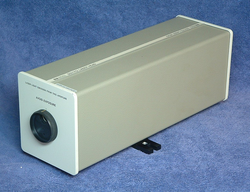
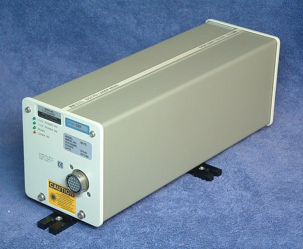
Typical HP-5517D Metrology Laser
The general appearance of all the 5517 and 5501B lasers is similar, but
those made by Agilent after around the year 2000 have a cheesy metal
shroud in place of the 2-piece gray cover. The 5517B, 5517C, and older
5517Ds, as well as all 5501Bs have a physically similar tube assembly
with a "long" glass laser tube. The procedure below is written for those.
Some newer 5517Ds, and the much less common 5517E/F/G lasers use a
"short" glass tube, but are otherwise also very similar. But minor
modifications to the procedure will be required for those if the
time comes.
The first step in the tube extraction process is to remove the laser
cover. If there is a shutter wheel on the front of the laser,
rotate it so the large hole is at the bottom. The flat-head screw engages
a quarter-turn fastener. Use a flat-blade screwdriver that just fits
the head and press it in and turn it counter-clockwise 1/4 turn. The screw
should pop out (but remains captive) and the front plate will come
off. Then, where there are covers as above, they can be spread apart
to remove. On the newer lasers, there is a rubber gasket of sorts all around
the metal shroud, so some force may be required to push in the front plate
to allow the screw to turn. Then spread the bottom apart slightly and
slide it off. Take care to not get it hung up on any components on the
control PCB. For a pre-2004 laser, the result should be very similar
to the photos below.


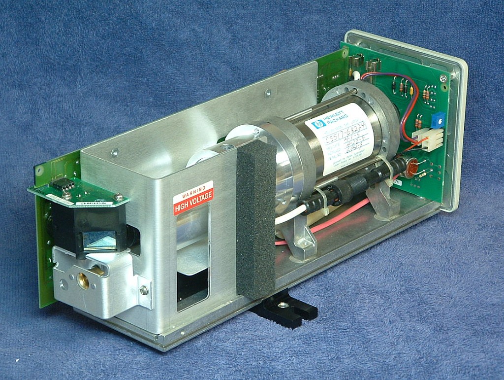
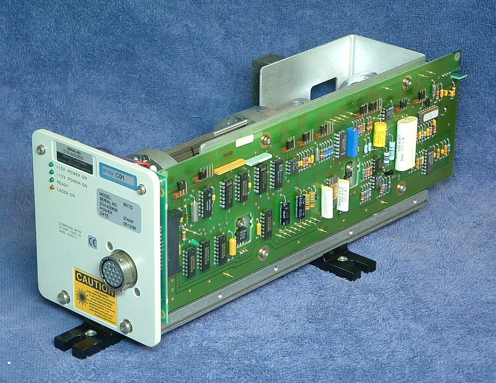
HP-5517D with its Cover Removed
Most newer Agilent use a control PCB with mostly surface mount parts
but it essentially emulates the older one so very little changes as
far as tube replacement is concerned. A very few 5517s have a third type
of PCB. And some newer lasers have an additional sheet metal cover
inside that necessiates a different tube assembly removal process.
Deal with those on a case-by-case basis.
Note: It is assumed that the laser tube has been determined to be
end-of-life and too weak to be useful. Thus, no actual testing of
its performance is provided here. If in doubt, test the tube and/or
the entire laser to confirm that the tube needs replacement and it's not
just a blown fuse!
Set up the laser on the Laser Alignment Table (LAT) so that it is in the
"Standard Position". Power up the laser. As long as a beam appears,
no matter how weak and no matter how long it takes to appear, or even if
the beam sputters or flickers, it will be possible
to check alignment. The center of the beam should be within +/-1 mm of
the marked position on the LAT screen for the 5517B/C and most 5517D
lasers. There are some versions that shift it by about 1 mm for reasons
unknown. If this laser is like that, mark the new position so when the
tube is replaced, it can be aligned to that mark.
The physical aspects of replacing and aligning the laser tube and optics
are quite straightforward in principle but the details can get messay,
especially with respect to extracting the glass tube from the magnet
assembly. Until a better technique is found than the one below, that
will represent the most single time consuming portion of the overall process.
The next step is to remove the tube assembly from the laser.
A typical sample is shown below. Some details may be different on yours like
the method of securing the magnet assembly (the 3 long screws) and the
style of the beam expander. But in general, it will be almost identical
in all other respects. On the left are the high voltage (HV)
connector and 2 pin cathode/heater
connectors. The back-end of the glass tube is sticking out the back. The
large shiny object is the Zeeman magnet. The black beam expander and
waveplate assemblies are at the right.
Typical HP/Agilent 5517B/C/D and 5501B Laser Tube Assemblies
Removal requires cutting any cable ties, disconnecting the black high
voltage connector and unplugging the 2 pin cathode/heater connector,
and taking out the 4 screws below the baseplate. It should then be possible
to maneuver the tube assembly out of the laser body.
Note: If there is a plastic cover on the back of the tube assembly, it has
a "short" tube. The procedures to replace it differ in minor details but
should be simlar to those for the "long" tube assumed here.
To be usable as a replacement for the custom HP/Agilent, it must satisfy very
specific optical, electrical, and physical requirements, as well as having
a life expetancy that makes the entire rebuild process cost effective.
At this time, there are no standard or even semi-custom commercially
available tubes that even come close in either
performance or longevity. While there are a hand-full of third party
companies claiming to be able to install non-HP/Agilent tubes, these
often have serious problems in both departments.
Even if the output power and REF frequency are acceptable, there
may be rogue modes, a beam size/profile that makes operation with
standard tools tricky or impossible, and short life. They will also
take longer to lock, and may be more sensitive to temperature.
Therefore, for the remainder of this document,
it is assumed that an identical HP/Agilent tube that has been regased or
totally refurbished will be used as the replacement. The term "regased"
means that the tube was simply refilled with pure He and Ne in the
apporpriate ratio and then sealed. The term "refurbished" means that
in addition to regasing, the tube may have been totally disassembled
so that parts like the cathode and mirrors could be treated or replaced.
Depending on the condition of the old tube, a complete refurbishment
process may be required to achieve adequate performance and life.
At present, only one company is known to be willing to do at least a
regas on these tubes, and then only if the glass tube is removed from
the magnet assembly. However, our first test with them is not yet
entirely statisfactory as the tube came back with either an external
leak or internal contamination.
Put marks or labels on the top front of the beam expander and waveplate
assemblies so that they can be replaced later on in the same orientation.
Remove the three screws securing the waveplate assembly and put it in a
clean platic bag to prevent contamination. DO NOT put the screws in the
same bag as they can damage optics!) Then remove the three screws
securing the beam expander and do the same. The beam expander may be
slightly stuck to the aluminum housing but should pop free with just
a bit of hand persuasion. That will expose the front-end of the glass
laser tube. This is about as far as it is possible to go esaily. :( :)
Our ultimate objective is to break it down (no pun intended...) to its
component parts without literally breaking anything:
Components of HP/Agilent 5517B/C/D and 5501B Laser Tube Assemblies
If the tube is definitely going to be regased or completely refurbished,
the wires can be cut close to the tube BUT NOT YET! Without cutting away
some of the potting compound at the back of the tube assembly to go deeper,
they would end up being shorter than desired.
The main problem is with respect to the rubbery potting compound used to
secure the tube inside the magnet assembly. While the stuff is relatively
soft, I am not aware of any solvent that will dissolve it without also
eating the metallic parts as well as rotting human internal organs (if
there are any at all). This appears to be some sort of expanded RTV-like
material which is impervious to modest heat as well - it may just get harder at
high temperatures. Furthermore, much of the potting compound that needs
to be removed is between the tube, and the magnet and the aluminum front
section, which is a gap of only around 2 mm, which makes it tough to get a
solvent into those areas.
Therefore, the only known methods of extracting the tube all require some
form of mechanical removal of the potting compound or total discombobulation
of the magnet and possibly the front section as well. In principle, the
easiest technique might be to slit the magnet and front section
lengthwise with a high speed low vibration diamond cutoff
wheel and then spread them apart and remove the two halves. With care,
the remaining potting compound is then easily picked off using a sharp
blade and other common tools. To install the refurbished tube, a commercial
magnet could replace the destroyed HP/Agilent magnet, and the front section
could be reconstructed with shims or hard Epoxy to fill the cutoff
wheel kurf. What is not known at this point is (1) whether the glass tubes
would survive consistently using this approach and (2) a supplier of
replacement magnets (but there should be many).
Thus the technique I have used to do a half dozen or so of these is to
cut and pick away the potting compound using a variety of tools normally
associated with torture - dental picks, long thin hex drivers, thin
pieces of sheet metal, coping saw blades, and so forth. These are all used
to gradually eat away at the potting compound at the back and in the
space between the glass tube and magnet. This requires on average about
three hours start to finish. As a practical matter, even trained
monkeys promised unlimited bananas would quit after doing one or two
of these. :( :) There has to be a better way. But here goes assuming the
tube assembly has been removed from the laser and the waveplates and
beam expander have already been taken off:
Note: Despite the extra effort, it may be worth practicing the following first
on tube assemblies that have no rebuild value, or at least ones where a
truckload is available. :) Then it won't be so bad to accidentally smash
a few.
- Remove the screws securing the feet and front section to the magnet.
(Three or six places.) Some of these may be quite tight.
- Remove the back feet bracket. It may be necessary to cut away a small
amount of the potting compound around the wires to clear what's left.
- Using an Xacto knife or single edge razor blade, careully cut away the
potting compound at the back of the tube just to the point of exposing the
connection points of the wiring to the tube terminals - 2 for the red and
purple cathode/heater and the anode. Cut the wires about 1/2 to 1 inch from
their termination to provide enough of a stub to reattach them after the
tube has been regased or refurbished. DO NOT go any deeper at this time.
The next step is to attempt to remove the aluminum front section.
- Carefully clamp the front section in a padded bench vice taking extreme
care to avoid contacting the nose of the glass tube. Gently rock the magnet
back and forth while twisting and issueing appropriate chants, incantations,
and 4 letter words. :) With some luck, the front section may come free of the
glass tube. Just remember that this is basically a fragile glass bottle
inside a massive metal structure. So, don't get carried away! If there
is any indication of it loosening, the continue and it may eventually come
free.
If this doesn't work, wedging a blade or two between the front feet bracket
and front section to attempt to lever the front section off may work but
again don't get carried away.
It may be necessary to pick away at the potting compound accessible through
the fill port on the top or side, or even from the front to loosen it up.
Going back and forth between this and the approaches above may eventually
yield results. But if this doesn't seem to be going anywhere, it may be
necessary to cut the front section apart, or at least cut off the front
of the front section to gain better access to the space between the glass
tube and aluminum housing.
Once the front section has been pulled off, it's time for the main event -
removal of the potting compound from between the tube and magnet.
- Use an Xacto knife or single edge razor blade to slice away the potting
compound at the back of the tube so that what remains is a cylinder about
5-7 mm smaller in diameter than the inside of the magnet. DO NOT
make it any smaller as the remaining potting compound will serve to protect
the remains of the wire and the fragile glass tip-off and feed-throughs
during the tube removal process.
- Now if you weren't having fun up to this point, here's your chance.
The idea is to get in between the tube and magnet and pick away at the
potting compound one bit at a time. This is by far the most time consuming
and boring part of this entire operation. My prinicple tool is a 1/16"
hex driver. Unless the tube is way off-center, this can get in in the
confined space easily and with care, will not damage the tube. But
don't force anything! Take your time. (I can hear the trained monkeys
already complaining.)
Work from both front and back but avoid going toward the center in the
back to prevent damage to the fragile tip-off and feed-throughs. Didn't
I say that already?
Note that if this is an older laser (typically with a manufacturing date
prior to around 1992), then the magnet consists of 4
segments. Working from the front, it's much easier to go one segment
at a time and then remove that magnet and set it aside. (It's not known
to what extent separating the segments results in some demagnetization
and reduced field strength when reassembled.) But virtually
all newer lasers have one-piece magnets. However, it's also easy to
break the tip-off and/or feed-through seals if care isn't taken in
removing the back segment.
- Once first contact is achieved - meeting of the excavation so that
a thin tool can be pushed all the way through - it will go faster. Then,
the idea is to work around the circumference until somewhat over 1/2
of the tube is free. A piano wire or coping saw blade may speed this
process, though I haven't tried them. Eventually, with some wiggling,
it should come free.
- Use a single edge razor blade or Xacto knife to carefully peel away
the remaining potting compount from all nooks and crannies of the tube.
Be particularly cautious in the are of the anode, tip-off, and feed-throughs.
It's still possible to screw this up!
- The result should look something like the photos below except perhaps
that the wires are cut short.

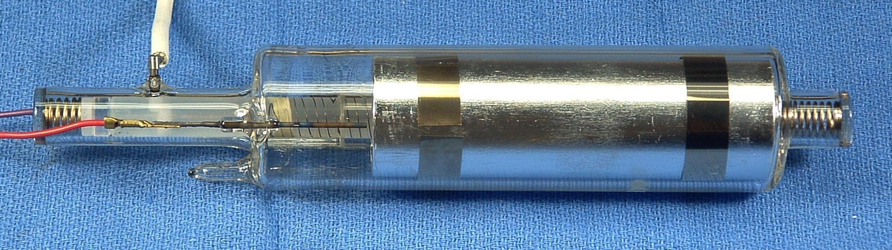
Typical HP/Agilent 5517B/C/D and 5501B Glass HeNe Laser Tube
It's a good idea to run the regased or refurbished laser tube and measure
its output power and mode behavior before installing it.
While the chances of a new tube being defective are relatively small,
it's been known to happen. And this will likely be one that has been
regased or refurbished where any number of things can go wrong.
- Temporarily mount the replacement tube inside the magnet intended to be
used, presumably the magnet from which it was extracted if that's how it
was done. For this test orientation is not critical, but setting it
at the original orientation (if known) would be preferable. Use insulating
material to approximately center it in the magnet with the anode terminal
at the end of the magnet.
- Carefully attach the ballast to the anode lead wire. Connect
the return to one of the cathode/heater wires (doesn't matter which
one).
- Power up the laser tube using the HeNe laser power supply and
extension cable. A regased or refurbished tube should light almost
instantly.
- Apply 5 or 6 VDC to the heater wires to accelerate mode sweep. This will
enable the tube to reach an equilibrium temperature that is similar to
that when it is locked.
- The output power will vary from a minimum to a maximum with a gradually
increasing period. The variation may be 25 percent or even more. The normal
lock point is generally at the minimum so that's the power level to check to
determine if it is adequate. The average output power will gradually
increase as the tube warms up so wait till the mode sweep has slowed
to a period of 20 or 30 seconds before testing for the minimum output power.
- The REF frequency can also be tested at this time. Place a linear
polarizer in the output beam and use the photodiode detectpr and oscilloscope
or frequency counter to test it. Without the waveplates, the orientation
of the polarizer does not matter. A beat signal will only appear for
a fraction of the mode sweep - 10 to 25 percent depending on the
model tube. The relevant value is the maximum frequency which
will coincide with the minimum of the outout power.

Checking Polarization Mode Orientation
(The photo shows the beam originating from a tube in an older Tube Alignment
Jig, but its use isn't necessary for this.)
- Reorient the tube and polarizer in either direction so that the axis of
the polarizer is at exactly +45 or -45 degrees AND puts the tip-off closest
to the bottom.
- Put a mark on the cathode end-cap of the tube to denote its top so that
it can be oriented the same way once installed inside the laser casting.
During this test, the output power through the polarizer should vary smoothly
from minimum to maximum power with the overall trend being slowly increasing
as the tube warms up. It should NEVER change suddenly, which would be an
indication of a faulty tube or one that doesn't have non-mode-flip optics.
After completing this test, but not before the tube has been on for
at least 1/2 hour, measure the output power directly from
the tube (without the polarizer). It should be at or near the maximum,
typically 3.5 to 4 mW for a new tube. but as low as 3 mW is acceptable.
Power down, discharge the tube/cable capacitance, disconnect the wiring,
and set the tube aside in a safe location.
(It's a good idea to take photos at each step of the way in the rebuild
process. Save all screws, washers, and other hardware in a pill bottle or
something similar.)
For the following, refer to the annotated diagrams above if necessary.
- Cut and remove all the nylon cable ties except those securing only the
wires to the HeNe laser power supply brick.
- Unplug the Alden connector. It may be rather tight - a thin
screwdriver or similar tool can be used to carefully pry it apart.
WARNING: There may be a painful charge
remaining on the tube anode and short prong of the Alden connector if the
laser was recently powered. To be safe, momentarily short the two
prongs together.
- Carefully slit the heatshrink covering the fat black cathode lead
connection and remove and discard it. Unplug the Alden lead from the
wire to the tube.
- Detach the top two connectors on the Control PCB (for the Photodiode
PCB and tube heater). They should come off easily if slightly
raised off the PCB and pulled out.
- Remove the two hex-head screws securing the tube optics/beam sampler
assembly to the chassis and carefully lift it clear of the tube and AOM
and set aside in a clean location or inside a clean antistatic bag.
- Remove the bottom two screws securing the front plate. CAUTION: Hex
"slots" easily stripped.
- Remove the two nuts securing the ballast resistor to the front of the
laser. Remove the top two long screws securing the front plate along
with the plastic spacers. CAUTION: Hex "slots" easily stripped.
- Remove the front plate and circular black plastic cap over the laser
tube housing.
- Remove the four screws securing the tube clamps and remove the clamps.
- Loosen the two screws securing the HeNe laser power supply brick
3 or 4 turns. This is necessary so that the plastic tube mounts do
not get hung up on the ends of the screws, which may protrude part way
inside the laser tube housing.
- Note the orientation of the tube based on the tip-off and label the top.
This will be required when checking its alignment in preparation for
transferring the heater winding. Carefully slide the tube assembly
out toward the front of the laser while guiding the cathode/heater
cables through the laser tube housing.
- Carefully slit the heatshrink or plastic tubing covering the black
cathode wire and heater cable and discard.
- Closely inspect the 2 pin heater connector where the fine heater wires
are crimped into the pins. If in doubt about their integrity, remove
the pins from the shell by depressing the locking tabs with a pointy tool
and solder the wires to the pins. Intermittent connections
can result in erratic behavior including locking at an incorrect temperature
and/or loss of lock.
- Using an accurate DMM, measure the heater resistance and record this
value to confirm that there are no shorts in the heater once it's been
transferred, or should a new heater winding need to be wound. (This
should be done with the heater near room temperature.)
On both ends of the laser tube in most of these lasers are circular
sheet metal terminal plates pressed onto the mirror mount stems and
soldered to anode and cathode wires. (On some versions, possibly only
some 7702s, there is simply a clip at the anode end.) If necessary, peel
off any Kapton insulating tape that may be covering the terminal plates. Then
use a thin screwdriver or something similar to carefully pry them
off the tube end-caps, working around the perimeter until they are free of
the inner (wider) portion. They will then slide off the outer section.
It is desirable to be able to reuse these so try to avoid serious damage.
They can be flattened out using a pair of pliers or a clamp. However,
if the metal snaps such that they can't be installed tightly on the new
tube, some other means of connecting the wires will be needed.
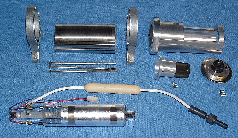
At this point, you should have the following:

Zygo Laser Head With Tube Removed
The tube is shown in the inset with its mounts and heater cable still attached.
But the anode and cathode wiring have been removed. The only other major parts
not included in the photo are the plastic cap/insulator and various bits of
hardware.
The TAJ consists of a heavy aluminum base on which are attached a pair of
two-piece HeNe laser head mounting brackets and a pair of 3-screw ring
mounts. The two-piece mounts mate with the outer (larger diameter)
surface of the plastic Zygo tube mounts. The 3-screw ring mounts are used
to adjust the position of the replacement tube for precise gluing into
the (reused) plastic Zygo tube mounts.

The Tube Alignment Jig
At each end of the Alignment
Jig is a plate with a ~0.7 mm hole drilled in the location where
the beam should pass if the tube is correctly aligned. There is some
adjustment range on these plates to accommodate slight variations in
alignment on different laser tube assemblies. However, variations
among different lasers tend to be quite small so that adjustment will
not normally be required.
This step sets up the alignment jig so that the replacement tube can be
aligned in the mounts so that it is as close as possible to the old one.
This can only be done if the old tube produces some sort of beam, even
if it is quite weak. Getting the alignment of the new tube matched as closely
as possible to the old one will minimize the turning mirror adjustments
needed after installation. If there is no way to get a beam, don't
touch the position of the end-plates on the Alignment Jig if they were
previously adjusted for a Zygo tube assembly. Assume they are close
enough. Skip to the next section. Otherwise, the tube will have to be
centered as best as possible without this assistance.
First determine whether a Type 1 (e.g., SP-117 - metal end-caps at both ends)
or Type 2 (e.g., 05-LHR-092 or 05-LHR-097 - metal end-cap at cathode-end
only) replacement tube is being
used. Since the plastic tube mount for the anode-end of the tube will
need to be reversed for a Type 2 replacement tube, there are two sets
of holes on the TAJ baseplate for attaching the tube clamp at that end.
The right set of holes (as shown in the photo above) should be used for
a Type 1 replacement tube and the left set for a Type 2. Tighten the
bracket mounting screws securely.
Loosen the two sets of three adjustment screws of the ring mounts
so they are almost all the way out. (These are not required for this
step must not interfere with the tube position.) Remove the top halves
of the tube clamps. Slip the original tube assembly into the TAJ taking note
of the HR/anode and OC/cathode locations, and oriented so that the
marks made in the previous step are at the top. Tighten the clamps
snugly so that the tube assembly cannot move or rotate.
Power up the tube using the Alden
extension cable. If necessary, loosen the alignment plates at each
end of the TAJ and position them so that the beams pass cleanly through their
respective holes and are as centered as possible. Don't get confused by
possible ghost beams that may be present, only the central strong one matters.
Tighten the screws on the alignment plates so that they cannot move. Recheck
their position and tweak as required.
Leave the tube assembly in the TAJ - the replacement tube will be installed
in place.

Original Zygo Tube in Alignment Jig (Type 1 Position) - Waste and Output Beams Pass Cleanly Through Apertures
Note that while it may be easiest to transfer the alignment from the old
tube to the replacement, if the old tube was a previous rebuild, this may
not be optimal. So, as with a situation where the old tube does not lase
at all, using a standard alignment where the tube is centered within the
plastic Zygo tube mounts can also be used.
Use an Xacto knife or single-edge razor blade to carefully slice the black
RTV blobs adjacent to the plastic mounts to minimize the possibility of
nicking the heater wire. Pull the tube out and clean off as much of the
residue RTV stuck to the mounts as possible, including what remains in
the holes (since these will be used to inject the glue that secures
the replacement tube). Set the TAJ (with plastic tube mounts installed) aside
for now.
Inspect the heater winding on the old tube for evidence of overheating,
charring, scraped insulating, etc. Some slight discoloration is acceptable
but anything more serious will render it unusable for the rebuild.
If the original heater winding is undamaged - as it most likely the case -
then it can be transplanted directly to the replacement tube in one
continuous process. However, if it gets screwed up and unravels all over
the floor, the construction of a heating winding from scratch will be
required. But that's for the advanced course. :) The following assumes
a normal transfer:

Zygo Tube with Protective Cap over Heater Cable and Replacement Tube Ready for Heater Winding Transplant
Before starting, identify the locations where the RTV Silicone will be
injected through the holes in the plastic tube mounts. These areas must
have direct glass contact free of any covering - heater wire or tape.
Mark a ~1/4 inch space with a marker for these on the replacement tube.
- For the Type 1 tube, start beyond the RTV area at the anode end.
- For the Type 2 tube, skip over these areas when doing the winding.
(This will place the end of the winding quite close to the cathode, but
as long as it is separated from it by small amount, there should be no
problem.
- Peel off the outer layers of Kapton tape at both the anode and cathode
ends of the tube leaving just enough in place to keep the winding secured.
- Roll up the heater cable and use your pill bottle or other means to
secure it against flexing during the winding process. (Shown above.)
- Attach a piece of adhesive tape (packing tape, Scotch tape, etc.) over
the winding at the anode-end of the original tube to prevent the winding
from unraveling.
- Carefully detach the end of the winding where the two wires are soldered
together and use a piece of tape to attach it to the replacement tube about
3/4 inch from the end-cap.
Note that the above photo shows an SP-117/A replacement tube. If using a
05-LHR-092, 05-LHR-097, or similar tube from Melles Griot, the anode-end
is rounded glass with no end-cap. The actual heater winding should start
very close to the end of the straight cylindrical portion of the glass
so the splice should be secured beyond it temporarily.
- Now's the fun part. Start the transfer process by rotating both tubes
at about the same rate so that the winding moves between them while
remaining taught without kinks and maintaining the wire pair flat on
both tubes. Regardless of the replacement tube being used, the actual
winding should start at the same location relative to the end of the tube
as it was originally on the Zygo tube.
- Periodically add a piece of tape to secure the end of the winding and
minimize the chances of an unraveling event.
A half completed transplant is shown below.

Heater Winding Transplant About Half Way Complete
- Continue the transplant until all the wire has been transferred. It
may be near the cathode end-cap but not touching it. Then remove
the heater cable protector and secure the end of the heater cable with Kapton
tape opposite the cathode tip-off. This may require leaving up to almost
1 turn of slack but that won't matter. Take care that there is no lumpiness
more than about 1/2 inch from the cathode end-cap where the plastic tube
mount will sit.
- Carefully clean up the anode-end so that the winding is secured with
multiple layers of Kapton tape and the actual splice is positioned slightly
toward the middle of the tube (overlapping the winding if desired, but
insulated from it with at least one layer of Kapton tape).
None of the wire should be closer than 1 inch from the anode end-cap and
there should be bare glass from about 3/4 inch to the anode end-cap or
mirror mount stem.
As one approaches the end of the transplant, it may be more difficult
to prevent the new winding from unraveling. So, additional care is
required, along with more frequent bits of tape to secure the winding
against such a catastrophe.
If done with care, the from start to finish will require 20-30 minutes.
For the more ambitious: Construct a jig that consists of a two pairs of
ball bearings with rubber cushions to hold the two tubes at their ends
so that the transfer can take place by simply unrolling the bad tube's
winding onto the new tube. This should make the process nearly foolproof.
- The anode-end tube mount of the TAJ should be installed in the position
corresponding to the replacement tube type - 1 (right) or 2 (left). Tighten
the screws securely.
- Wrap approximately 2 turns of tape around the tube
at the locations where the 3-screw ring mounts are positioned on the TAJ.
This will protect the heater winding from possible damage from the
screws. This can be electrical tape, kapton tape, Scotch tape, etc.
- Slip the tube mounts loosely onto the ends of the tube.
- For the Type 1 replacement tube (SP-117/A), the larger diameter
sections should face each-other. The anode-end mount should be
approximately 1/4 inch from the end-cap.
- For the Type 2 replacement tube (Melles Griot 05-LHR-092 or -097),
the anode-end mount must be flipped around because otherwise, there's
no tube to put it on.
- Note the location of the polarization mark you put on the tube in a
previous step. This is should be oriented at 45 degree to horizontal
or vertical AND with the tip-off of the tube toward the bottom.
- Position the tube assembly in the TAJ so that the shoulders on the
plastic tube mounts are flush with the appropriate side of the TAJ
tube mounting clamps. For the Type 1 tube, they are on the outer
sides of the mounts; for the Type 2 tube, they are on the right
side of both. Tighten the tube clamps so the plastic Zygo tube
mounts cannot move. Double check that they are squarely mounted and
positioned correctly.
- While maintaining the proper position of the tube (including the
proper 45 degree polarization orientation), rotate the screws of the
3-screw ring mounts clockwise until they gently
contact the tube (via the electrical tape) and then adjust them so the
tube is approximately centered within the plastic Zygo tube mounts.
- Attach the Alden extension cable with the red wire with ballast resistor
clipped to the anode (glass-end) and the black wire clipped to the cathode
end, both preferably mostly on the portion of the mirror mount step closest
to the tube.
- Plug the Alden connector into the HeNe laser power supply brick and
apply power to the laser. There is no harm is powering the Control PCB
without the photodiodes and heater being connected.
- Check the alignment at both ends. As with the original tube, the beams
should be centered in the small holes in the end plates.
- If adjustment is required, use the 3-screw ring clamps to center
the beam so it passes through each hole.
It will probably be necessary to go back and forth between the
anode and cathode ends to optimize the alignment. Snug up the
screws so that the tube cannot move during gluing and re-confirm
beam position and 45 degree polarization orientation.
- Once alignment is optimal, fill the mount injection syringe with
a couple cc of RTV 598 from the tube directly (don't bother with the
plastic nozzle). If the black cap is replaced tightly, the RTV will
remain usable for quite awhile.
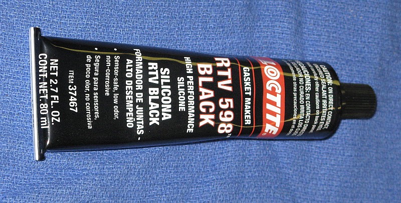
Loctite High Performance Black RTV 598 Silicone for Securing Laser Tube
- Inject RTV 598 Silicone through the holes in the plastic Zygo tube
mounts so the resulting blobs are about the same size as the original
ones. Start with 3 holes at approximately 120 degrees and then do the
rest. Not all the holes need to be done on the first round. A half
dozen approximately equally spaced should provide enough strength
once cured so that the rest can be done once the tube has bee removed
from the TAJ. But allow the RTV to fully cure (2 hours) before moving
anything. WARNING: Take care near the anode-end of the tube
to avoid a shocking experience!
Power back up and double check that nothing moved. Allow to cure overnight
(with power off). Trim any excess after curing.
The photo below shows a completed Type 2 tube assembly mounted in the TAJ
along with the glue syringe positioned to fill one of the holes. Note that
this tube assembly is not one of ours, but one done by another rebuild company,
which explains why the RTV isn't black. :)

Type 2 Replacement Laser Tube with Heater Winding Installed in Alignment Jig
The ballast resistance consists of a pair of 45K ohm wire-wound resistors
in series for a total of 90K ohms sealed in black plastic pods. In the
original laser, one is attached to the front with nuts while the other
is simply buried under the jumble of wiring.
The resistors run hot and despite being way overrated - spec'd at 5 or 6
watts and dissipating only 1-1/8" watts - the resistance
tends to increase on high mileage lasers. If not dealt with, this can
eventually result in erratic behavior and/or HeNe laser power supply
and/or tube failure. With the Alden connector wiring assembly
disconnected from the HeNe laser power supply, use a DMM to
measure the resistance between the
laser tube anode contact and the shorter prong of the Alden connector.
If the reading is not 90K (+/-1%), poke a straight pin through
the insulation of the wire half way between the two ballast resistors and
measure the resistance of each one. Replace a resistor if more than
about 45.5K ohms. To be totally safe, replace them both regardless of
the measured value. It's a small price to pay for insurance against
the possibility of random problems that can require days to track down
or worse.
The present technique uses 5 watt 45K Vishy CW00545K00JB12 resistors
insulated with glass tubing about 8 mm ID. The leads are cut as short
as reasonable (about 6 mm), looped, and soldered to HV wire. Heat-shrink
tubing is used to cover the ends of the glass tubes for support and
appearance, but is not depended on for insulation. The original Nylon
ties are trimmed to retain only the fastening loops, and then replacement
ties are passes through the slot.
Inspect both the anode and cathode contact plates
for major damage including any signs of cracks,
which would render them unusable. Before installation, they should be
approximately flat. If not, use a pair or pliers or a clamp to flatten.
For the cathode-end, line up the cutout of the plate
attached to the black wire with the tip-off and press the plate in place
all the way to the end-cap. It should be a tight fit and hold very securely.
Transfer the black plastic tip-off protector from the original Zygo tube to
the new tube if possible should there be no glob of Epoxy there already.
(This is protection for human flesh more than the tip-off.)
Line up the anode plate attached to the red wire and ballast resistor in
the same way (though there is no tip-off) and press in place in a similar
manner. Wrap several layers of 1 inch Kapton tape around the tube and
plate to act as insulation preventing arcing between the tube and metal
laser tube housing.
Cut a piece of HV insulation material exactly 1.5 inches by approximately
6 inches. Roll this up and slide it in surrounding the tube at the anode
end to further prevent arcing. It should fit between the narrower portion
of the plastic tube mount and and expand out to fill the housing. Use a
nipper to cut out a small notch so that the anode wire can get through at
the slot.
- Pass the cathode wire and heater cable through the laser tube housing
from the front and then gently push the tube assembly in behind it. If
the mounting screws for the HeNe laser tube were retightened, they will need
to be reloosened to clear the plastic tube mounts. Align the tube so that
the mark made earlier is precisely at the top. Position the tube so that
the plastic mounts line up with the locations for the tube clamps. Install
the clamps and tighten only gently as they will need to be loosened again
to adjust the tube orientation.
- Using a new cotton swab and one drop of isopropyl alcohol, clean the
surfaces of the mirror glass at both ends of the tube. With another clean
dry cotton swab, *gently* dry the glass so the AR-coating of the output
(front) mirror is a deep blue or purple with no streaking or other visible
contamination. The outer surface of the back mirror should be shiny and
free of debris (like tape adhesive or RTV residue) but it is not AR-coated.
- Angle the cathode wire and heater cable up and install the tube
optics/beam sampler assembly. The wire and cable should not get pressed
by the optics cover. It may be necessary to carefully bend them to make
this happen. Position the optics housing against the tube housing and secure
with the two long screws and washers previously removed.
- Plug the photodiode cable into the Control PCB (second from the top).
Route the cathode wire under everything else to the area of the Alden
connector. Plug the heater cable into the Control PCB (top).
- Carefully route the anode wire, ballast resistor, and Alden connector
through the front of the laser, positioning the wire in the slot. Attach
the Alden connector. Cut a piece of 1/4 inch heatshrink about 2 inches
in length and slip it over the cathode wire. Attach the cathode wire and
black wire from the Alden connector using the FastOn. If you don't have
heatshrink, a few turns of electrical tape will suffice - there is no
voltage on these wires.
- Using a new cotton swab and one drop of isopropyl alcohol, clean the
surface of the mirror glass. With another clean dry cotton swab, *gently*
dry the glass so the AR-coating (if present) is a deep blue or purple
with no streaking or other visible contamination. While no useful beam
exits this end, debris on the mirror can result in back-reflections which
can destabilize the laser.
- Gently install the black plastic end-cap and then position the front
plate, securing with the two short screws at the bottom and two long screws
at the top. As the top screws are threaded in place, insert the plastic
spacers and then the ballast resistor nylon clips. Tighten all four screws
securely. Install the two nuts that hold the ballast resistor in place and
tighten finger-tight, then another 1/4 turn or so with a wrench.
- Carefully inspect everything for areas of concern (whatever that means!).
Refer to the original photos of the laser interior. Except for the absence
of cable ties, the appearance should be nearly identical.
Attach the DB25 and apply power. The new tube should come on almost instantly.
If your alignment was done well, there should be a bright beam out the front.
If not, well, some more work will be needed but that can wait. :) Just make
sure there is a beam at the AOM or turning mirrors. If the tube does not come
on, power down immediately and find out why! The Alden connector might not
be fully seated or your forgot the step where the cathode wire was attached,
or the HeNe laser power supply connector was not plugged in or was swapped
with the AOM power connector, or something. Look and listen for anything
unusual. There should be no visible arcing, 6 foot flames, sizzling sounds,
or major explosions.
Check the optical power at the turning mirrors. The average value should be a
bit less than 1/2 that of the raw output of the replacement laser tube.
(The power will vary by as much as 2:1 or more with a cycle of a few
seconds due to mode sweep - this is normal.) If it is
much less, the tube optics/beam expander may have been poorly positioned,
and its mounting screws should be loosened so it can be adjusted.
Or there may be something pressing on one of the tube's mirror
mounts misaligning it, probably the one buried inside the tube
optics/beam expander housing. In that case, the cabling will
need to be redressed.
The POWER and UNSTABLE LEDs should be on.
Allow the laser to run for 5 minutes or so and then power down.
At this point, those who are anal retentive would want to test the output of
the tube to assure that only the desired longitudinal mode is being passed.
The presence of significant power in the second longitudinal mode that's
lasing (but should be blocked) can potentially result in small positioning
errors over distances on the order of 10s of cm. How large the output power
in the second undesirable mode needs to be before this becomes an issue
isn't known. But having seen at least one botched rebuild where this was
apparently not done, it is highly recommended! :)
The test will require the use of a Scanning Fabry Perot Interferometer (SFPI,
also known as a laser spectrum analyzer) to display the mode structure of the
laser. If possible, the actual adjustment of tube orientation should be
performed after the laser has locked so that the modes aren't moving around
confusing interpretation. When adjusting tube orientation, make only small
changes and go slow - sudden or large disturbances may cause the
laser to lose lock.

Scanning Fabry-Perot Interferometer Positioned in Front of Zygo Laser
While the photo shows the SFPI very close to the laser, it's better to
Position it further away since alignment that results in the best
display will result in a reflected beam directly back to the laser.
There is the potential for that to destabilize the laser causing it
to lose lock. Keeping it just a little bit off-axis will help greatly,
and positioning the SFPI head further away will make this easier. A distance
of a 2 or 3 feet would be more than adequate. Having said all that, it
worked fine as pictured. :)
Adjust the thumb-screws so they are approximately in the middle of their
range and shim the laser if necessary so that the beam is horizontal and
hits in the center of the SFPI input lens.
For the SFPI provided, attach the cables adhering strictly to the color code!
- High Voltage Scan Amp (red): SP-476 HV Scan Amp to
BNC on side SFPI head.
- Blanking Output (yellow): SP-476 Blanking Output to
Ext Trigger (or Channel 2) of scope.
- Photodiode Input (blue): SP-476 Photodetector
Input to BNC at back of SFPI head.
- Vertical Amplifier (green): SP-476 Vertical Amplifier
Output to Channel 1 of scope.
The SP-476 controller should
be set for "Free Run", maximum sweep rate (Time fully CW), X1 Dispersion,
with the Variable and Centering controls about mid-range.
The scope should
have the Vertical Amp (green) going to Channel 1, Trigger Out (yellow) going
to Ext Trigger or Channel 2 (with the scope set for triggering using
Channel 2). Start with Vertical Gain second position from CCW and Variable
centered. On the rear panel, the slide switch above the HV Scan Output
should be set to low or 300 V and the Blanking Output control should be
set fully CW. With these settings, there should be something on the scope if
alignment of the SFPI head is reasonable. Fine tune alignment for maximum
amplitude and adjust controls for appropriate horizontal and vertical
display. Refer to the
SP-476 Operation and Service Manual for more details.
If the beam out the front of the laser is weak or absent, use a
small mirror mounted in a "third hand" to redirect the beam from
just after the AOM or prism to the SFPI. (This may be the best approach
regardless since the beam will be stronger there
and less subject to intensity and angle fluctuations when the
tube is rotated.) The beam sampler assembly must be in place and secured.
Ideally, if the tube is optimally
oriented with the polarization axes at +/-45 degrees, only the desired
mode should be present, showing up as a single peak spaced at the FSR
of the SFPI. In practice, it may not be possible to entirely suppress
the second mode since the polarizer at the output of the laser tube isn't
perfect. But it should be of very low amplitude and only appear once the
SFPI photodiode gain is greatly increased compared to a normal display.
To minimize the amplitude of the second mode, the tube clamp near the
anode-end of the tube should be removed and the other one loosened.
Then, rotate the tube very carefully by a small amount one way or the other
with a pointy tool moving the exposed tube mount until the second mode
is reduced in amplitude as much as possible. It should certainly be
way under 1 percent of the amplitude of the main mode, and probably under
0.1 percent. Using a small drill bit in a hand chuck to make an indentation
near the top of the plastic mount will ease in being able to grab it for
rotation. (But don't drill clear through and into the heater winding or
tube!) When the optimal orientation is found, tighten the cathode-end
tube clamp and replace and tighten the anode-end tube clamp. Double check
that the second mode is still minimal.

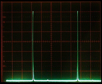
Scanning Fabry-Perot Interferometer Display of Single Component After Locking - ~8% MM, ~1% MM, Pure SM
The three photos shows varying degrees of alignment perfection from rather
poor where the tube orientation is several degrees away from optimal
with the unwanted mode at about 8%, to absolutely pure single mode.
As a practical matter, the setting resulting in ~1% leakage would
probably be acceptable, but getting at least 10 times better should be
possible. Increase the sensitivity of the scope vertical when the unwanted
mode is no longer visible with the main modes filling the screen. With
care in alignment, it should dissappear beneath the noise floor.
Note that single peaks like those in the photos
are what would be seen if a polarizer were placed
in the beam to select the horizontal or vertical component only. Where
both components are present (no external polarizer with the AOM enabled and
aligned), a decent SFPI will be able to resolve twin peaks very close together
as shown below.


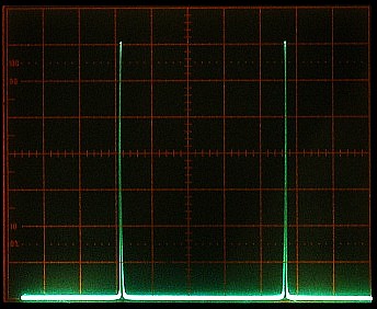
Scanning Fabry-Perot Interferometer Display of Twin Components After Locking - ~10% MM, ~1% MM, Pure SM
How well these show up, and to some extent how accurately their relative
amplitudes reflect their actual intensities, will depend on the the quality
of the SPFI and the care with which the alignment is performed.
(Should this test be done after turning mirror and AOM alignment, these may
need to be fine tuned - again.)
If the original tests for polarization axes were done very carefully and
the axis was labeled equally carefully and the tube was installed even
more carefully, this added effort is probably excessive. But if
an SFPI is available, it's quick and adds a level of confidence to the
quality of the rebuild and is highly recommended.
If the heater winding was transplanted undamaged in its entirely, then in
theory the set-point adjustment should not need to be changed. However,
in my experience, the set-point temperature usually needs to be reduced
by a small amount, possibly due to the difference in power dissipated in
the non-Zygo laser tube, which may have a slightly lower operating voltage.

Analog Control PCB Showing Relevant Test Points and Pots
The two relevant test-points are:
- Heater Voltage: TP15, second wire loop away from pots towards
center of PCB (in the large red box). The voltage will switch between
approximately +14 V for 4 seconds and 0 V for 1 second during warmup.
The 4 second period is to apply constant power to the heater while
1 second period is to allow for the controller to measure the heater
resistance, which is used to determine when to switch from the warmup to
the lock state. Once the temperature set-point has been reached, TB15
will be the actual voltage on the heater that is maintaining lock.
- Photodiode Signal: TP3, center socket/pin of mini-shielded jack (in
small red box). (Use a 1-2K ohm 1/4 watt resistor with all but 1/8" at the
end insulated pushed into the socket. The resistor will isolate the signal
from accidental shorts without affecting the reading significantly.)
The voltage should swing between -9 V (or more
negative) and +9 (or more positive) during mode sweep as the tube
warms up. However, it won't be smoothly varying due to the
periodic switching of the heater power (4 seconds on, 1 second off)
to monitor heater resistance, which causes rather dramatic fluctuations
in the output amplitude, especially toward the end of the warmup period.
Put a DMM set to DC Volts on Test Point 15 so that heater activity during
warmup and locking can be observed.
Once the replacement tube has been installed, the laser should be powered
up until it locks ("OK" LED comes on). During warmup, the voltage on
TP15 will switch from about 14 VDC while the heater is being driven, to
0 VDC while the resistance of the heating winding is being measured.
The voltage on TP3 (center pin of the mini-shielded jack in the small
red box) should swing between -9 V (or less) and +9 V (or more). (But
due to the periodic switching of heater voltage, this is not a
smooth variation.)
Locking should occur in less than 15 minutes. If this does not occur,
the set-point is probably too high. Slowly turn the
trimpot closest to the connectors ClockWise (CW)
in 1/8th turn increments, about every
10 seconds for each increment. Unless someone really messed up this setting,
within about 1/2 turn max, the "Unstable" LED should go off and if viewing
the output on a graphing laser power meter, the power should begin to
stabilize about mid-way between its min and max values. 1/2 turn
changes the lock voltage by approximately 6 V.
Check the voltage on TP15. If you recorded the lock voltage with the
original tube, that is the value to aim for. If not, while I do not
know what the Zygo procedure
for setting the temperature is, my recommendation is that in a normal
environment - around 20°C - the initial value should be 10-12 V,
declining to 6 to 7 V after several hours with the cover on the laser.
If it goes too low, the voltage may start oscillating and lock
will be unstable.
If it locks at too low a heater voltage,
power down for 5 minutes and rotate the trimpot 1/8th
turn CCW, then power up and see if it locks at a better voltage. If it starts
too high, turn the trimpot CW 1/8th turn. Do this incrementally until the
desired start voltage is reached. Then power off for 1 hour and double check
that is relocks at the same voltage and reaches a steady state value
of 6 to 7 V after several hours with the cover on. Adjust as needed. This
isn't as hard as it may sound, but it may take several iterations (and
many hours of linear time) to there. :)
Note that the alignment of the turning mirrors and AOM interact
to some extent, so some iteration may be required to optimize both.
If the tube alignment was done carefully, turning mirror alignment should
be minimal, simply peaking the output power of the laser. However, as a
practical matter, this would be very unusual. If done sloppily,
there may be no beam at all out the front and it might not even be possible
to adjust the AOM to get high enough power in the vertical mode
(next section). If the AOM is known to be out of adjustment (for example
having been swapped in from another laser), then doing AOM alignment
first may auotmagically correct or partially correct problems with overall
alignment.
Keep in mind that with the AOM powered, there are actually several "orders"
of beam present. With it not powered, there are only two - the "ordinary"
(horizontal) and "extraordinary" (vertical), side-by-side.
Initial alignment may be easiest and least ambiguous
if the AOM RF driver DC power is unplugged (7701 - bottom connector on
the control PCB) or the RF is disconnected (7702 - SMA connector on
control PCB). With a horizontal polarizer on the output, alignment
will be optimal when the beam power is maximum.
There are two adjustments that are more or less independent:
- Horizontal alignment adjusts the turning mirrors so the
beam passes cleanly through the spatial filter (if present)
and is centered on the beam expander. The spatial filter acts as a point
source horizontally, so horizontal output alignment will be correct when
these two conditions are met (or at least the same as they were originally).
For lasers without a spatial filter, this step will also set horizontal
output alignment. The horizontal alignment uses the right adjustment
screws on the turning mirror mounts. Clockwise rotation of the horizontal
screws moves the beam to the left.
DO NOT touch any adjustments on the spatial filter or even remove and replace
it (as that can also change alignment) UNLESS you have passed the Advanced
Course and suspect or know that someone before you has messed with it! :)
The spatial filter alignment will not change on its own unless the laser
was run over by a 10 ton truck (and then likely not even then).
- Vertical alignment adjusts the turning mirrors so the beam
passes through the center of the beam expander AND is perfectly horizontal
exiting the laser. The vertical alignment uses the bottom adjustment
screws on the turning mirror mounts. However, because the mirrors are
oriented at 45 degrees, these adjustments do not result in strict vertical
movement but affect passage of the beam through the vertical slit in
the spatial filter (if present) and/or the horizontal position as well.
Though they will tend to cancel overall, small increments must be used
so as not to lose the beam entirely or jump to a different AOM order.
Clockwise (CW or right) rotation moves the beam up ("right raises, left
lowers").
It's also possible to use the common (corner) screws for this.
I haven't come to any firm conclusions as to which set of screws is
easier but I seem to prefer using the bottom screws.

Turning Mirrors 1 (Left) and 2 (Right) Showing Adjustment Screws and Added Insulator
The adjustment screws have hex "slots" (not visible in the photo), though
in a pinch, grabbing the threaded part with a pair of needle-nose pliers
to make fine adjustments is not out of the question! (Just take care not
to smash the mirror!) Remove the rear plate to provide access to all 4
turning mirror adjustment screws. Place an insulating sheet between the
back of the Control PCB and the adjacent turning mirror mount to prevent
contact with the adjustment wrench and possible short circuits.
Replace the laser in the standard position on the Laser Alignment Table.
Power up the laser and check the output beam profile - if any. If it's nice
and bright and symmetric, congratulations, your tube alignment was done
well. :) Given that this state of affairs is somewhat unlikely, alignment
will be needed.
The turning mirrors have three sets of adjusting screws.
The screws at the right side top (in the photo) of each mount control the
horizontal alignment (H). The screws at the bottom of each mount control the
vertical alignment (V). But since the mirrors are oriented at approximately
45 degrees to the optical axis of the laser, they also affect horizontal
alignment. The common screws (C, upper left corner of each mirror mount
in the photo) affect both horizontal and vertical alignment as well.
Either the bottom (V) or upper left (C) pair of screws can be used for vertical
alignment. Adjustment screws should always be used in pairs (V and V
or H and H or C and C) to "walk" the mirrors. But don't go between
them or confusion will be more acute than it already is. :)
The adjustments require two 3/32" hex keys. One key will need
to have its short leg ground down or cut off
until only about 1/8" extends for the right-most adjustment of
Turning Mirror 2 so it can clear the
Control PCB. A piece of insulation material such as cardboard or plastic
MUST be placed between the mirror mount and the PCB to prevent short circuits.
If there is no beam coming out the front of the laser, place a piece of white
paper in the beam path before the spatial filter and determine which direction
to move the mirrors to center the strongest beam there. Turn the right or
bottom adjustment screw for Turning Mirror 1 (left in the photo) to center it.
The horizontal adjustments should be done first to center the beam horizontally
on the input to the beam expander. Only very small rotation of the screws
is required. The beam moves to left when the pair of horizontal screws are
turned clockwise. The movement is very sensitive so a *very* small
changes should be made alternately to center the strongest beam.
Then the vertical adjustments can be done to center the beam vertically
on the beam expander and fine tune the angle with which it hits the
beam expander. This vertical alignment will require
using both the vertical and horizontal screws because they are not kinematic
(orthogonal or independent) adjustments.
Initial adjustments can be performed while the laser is warming up but the
final adjustments should only be performed once it has stabilized so that
small changes in output power can be observed on a laser power meter.
At this point, there should be some beam out the front of the laser.
Check to see if it seems to be cut off at the top or the bottom. Use
the bottom adjustment screw for Turning Mirror 1 to make
the beam profile symmetric.
Next check the beam position on the LAT screen compared to the reference
mark put there during initial testing. If it is centered on the mark,
vertical alignment is fine. If not, use the bottom adjustments screws
alternately to walk it to the center. For example, if the beam is too
high, CCW rotation of the adjustment screws will lower it. Remember:
Left (CCW) lowers; Right (CW) raises. Alternative rotate the screws in
small increments to maintain the beam within the horizontal extent of the
spatial filter slit.
Note that there are actually multiple positions for horizontal alignment
that will result in an output beam and two will have relatively strong
power with both F1 and F2 (via the AOM) present. They correspond to the two
side-bands of the AOM, but one
of them will have more total output power than other. That's
obviously the one that's desired. There are several ways to confirm
the correct selection (any one of these is a sufficient test):
- Unplug the drive to the AOM. That should kill the vertical polarization
entirely. If it instead kills the horizontal polarization, you've got the
wrong pair.
- When the AOM is misaligned, the horizontal polarization should be maximum
and the vertical will be near 0. If it's reversed, you've got the wrong
pair.
- Increasing the AOM drive should increase the vertical (the trimpot on 7701
or AOM DAC COUNT setting on 7702). If it increases the horizontal, you've
got the wrong pair.
Typical output power from the laser
for a tube with a raw power of 3.5 mW would be about 600 to 650 µW.
If the laser is only producing 300 µW with a nice symmetric beam
and both F1 and F2 are present, it's probably aligned to the wrong side-band.
Fix it. :) However, I've seen lasers where the power difference wasn't
that dramatic, so perform one of the checks, above.
In addition, alignment of the AOM also affects the beam position slightly.
So, if it needs to be adjusted to peak the vertical polarized output,
the horizontal turning mirrors may also need to be readjusted.
In short, this is an iterative process with the objective of maximizing
laser output power with F1/F2 being as equal as possible while also
maintaining a reasonably symmetric beam profile for both. However, it
may not be possible for either to be perfect.
Once complete, power down and replace the rear plate.
Should it not be possible to obtain proper alignment, it will be necessary
remove the spatial filter and do the following (with the laser properly
positioned on the Laser Alignment Table:
- Adjust the two turning mirrors so that the beam is centered on the target.
- Remove the front optic (slit) plate of the spatial filter and install
the spatial filter in the laser. Tighten its fastening screws.
- Loosen the four (4) hex screws at the top of the spatial filter that
lock the top assembly.
- Use the two recessed screws in the spatial filter top assembly to move
it horizontally to center the beam horizontally at the output collimator.
(The screw on the right moves the assembly to the right; the one on the left
moves the assembly to the left.) Then lock the assembly down and tighten
both adjustment screws.
- Loosen (but do not remove) the spatial filter input optic (lens) plate.
- Use the 2 recessed set-screws on the side of the plate to move it up
and down to center the beam vertically.
(The one on the top moves the assembly up; the one on the bottom
moves the assembly to the down.) Tighten the fastening screws and
adjustment screws.
- Replace the slit optic with the fastening screws barely snug.
- Use the two set-screws on the top of the slit plate to select the
proper AOM order (the one that is strongest and has the AOM producing its
vertically polarized component). This is easiest down by backing both
screws out until the plate can be moved back and forth fully by hand,
finding the correct position, and carefully turning the screws in until
they bottom on the plate. Then tighten the fastening screws and the
adjustment screws while checking that alignment doesn't change (much).
- Go back and fine tune the turning mirror adjustments as described above.
Use a polarizer to check the relative power in the horizontal and vertical
modes. If they are not nearly equal AOM adjustment will be required.
Most likely, the horizontal mode is much stronger than the vertical mode,
which may not exist at all! If so, loosen the two screws securing the AOM
and gentle rotate it about its vertical axis in an attempt to maximize
the power in the vertical mode. Unless the tube alignment was done very
poorly, it should be possible to get the modes to be nearly equal. The
amount of angle adjustment range is very small, and the precise point of
maximum power is a fraction of 1 degree. Note
that they interact - increasing the vertical mode decreases the horizontal
mode. However, striving for maximum vertical power is acceptable even if
it turns out to be higher than the horizontal power, as there is an adjustment
on the AOM driver that can lower it. Take care not to put your grubby
fingers on the AO-coated front and back faces of the AOM!

Acousto-Optic Modulator (AOM) Showing Mounting Screws
If the mode balance is now within 5 percent, leave well enough alone.
(The spec for the 7701 is 20 percent, but getting to better than 5
percent will usually be possible.)
But to fine tune, the trimpot is on the AOM driver mounted on the laser
base under the HeNe laser power supply. Slightly loosen the rear screw
holding the HeNe laser power supply in place, and loosen and lift (but
do not remove entirely) the front screw so the brick can be rotated
clockwise enough to clear the AOM driver box. The access hole is on
top. CW increases the vertical mode power. If either screw is removed
entirely for some reason, when replacing, don't forget the flat washer(s)!
Should it not be possible to find any orientation of the AOM that results
in acceptable vertical mode power even with the AOM driver adjustment
and it is known that the AOM is functioning correctly, this probably
means that the tube alignment is way off.
Time for duct tape, bailing wire, and hot-melt glue. :) (Been there,
done that.)
It's also possible to adjust the AOM response with shims under the AOM. Your
laser may in fact have a brass plate to set AOM height. Removing that or
adding another shim may help.
Recheck the H/V mode balance after full warmup (1 to 2 hours) and readjust
the AOM driver trimpot if necessary.
Place a continuous reading power meter in the beam so it monitors the
laser output power. This doesn't need to be precise so any reasonably
linear detector will be adequate such as a back-biased photodiode and
DMM on the mA range.
Unplug the photodiode connector and record the minimum and maximum readings
during a couple cycles of the unlocked mode sweep. Plug the connector back
in and allow the laser to reacquire lock.
Adjust the trimpot FURTHER from the connectors so the lock point is mid-way
between the min and max readings recorded earlier. Take care not to touch
the temperature set-point trimpot or you'll be doing that adjustment all
over again!
Touch up the turning mirror alignment to maximize total output power.
This should only require the slightest of adjustment of the screws for
Turning Mirror 1. Once this is complete, remove the
insulating sheet between Turning Mirror 2 and the Control PCB.
Using pure isopropyl alcohol, gently clean the accessible optics. Dirt and
other contamination can reduce the laser output power by 25 percent or more
even if there is no visible degradation in the beam quality. A
film on the AOM surfaces in particular can also result in the ratio of
F1:F2 changing periodically with respect to temperature due to etalon effects.
Remove the cover plate on the side of the tube output optics and clean the
output mirror surface of the tube and the window/beam sampler. Replace the
cover. Then clean the angled window of the tube output optics, AOM, prism,
turning mirrors, and the input lens of the spatial filter (if present).
It's best to use proper laser optics cleaning techniques
to avoid damage to the delicate coatings, particularly on the turning mirrors.
But with care, cotton swabs can be used with very light pressure. First blow
off any dust with an air bulb, then put a drop of alcohol on a NEW
cotton swab and wet the optic surface while gently wiping in one direction.
Finally, even more gently, dry it with another NEW swab. Ideally,
the surfaces of the beam expander optics should also be cleaned, but accessing
them may be difficult. At this point, there should be very little scatter off
the surfaces from the beam. Again, use a NEW swab for each surface to
avoid transferring contamination from the used swab to the optic. Did I
mention that only NEW swabs should be used and then discarded? :)
The locked output power should now be between 1/6th and 1/4th of the raw output
power of the replacement laser tube. For example, if its output power is
3.4 mW, this would be between 567 µW and 850 µW. A bit more or
less doesn't matter, but if it's much lower, there is a problem with beam
alignment, the wrong side-band of the AOM is being selected by the spatial
filter or beam expander, or something else is causing the output power from the
tube to be reduced. This needs to be addressed.
Power off and install nylon cable ties to secure the wiring in more or less
the same way it was originally. It doesn't need to be identical to the
original as long as the wiring is secure. Make sure wires that could
interfere with the internal beam are tied well out of harm's way. For
that single strange tie at the corner of the Photodiode PCB, simply cut
off the extra strip and slip a thin cable tie through its slot.
The 7701 has a mercury column run-time meter stuck on a surface near
or on the AOM driver box. It may be desirable to cut its wires, remove
it, and clean up the sticky pad residue.
Double check that all screws are secure. Turn the laser upside-down and
shake it a bit so that any runaway hardware, dead bugs, or other
debris falls out. :-)
Replace the lid with any beam caution labels toward the front. Tighten
the screws snuggly.
Apply power and allow to lock. Recheck output power and beam alignment.
YOU ARE DONE!
Optional: Set up the laser with a polarizing beam splitter, dual photodiodes,
and PC-based data acquisition system, and capture output at a minimum
50-100 samples per second for 24 hours or more. Inspect the data to assure
that there are *NO* mode flips, glitches, or other unsightly blemishes in the
laser's output power for either polarization after the laser has locked. This
would catch infrequent (but fatal in terms of performance) problems in the HeNe
laser power supply, ballast resistance, or wiring; locking or AOM
driver problems with the control PCB; or a misbehaving tube - all
conditions that are likely to be missed by the
control PCB in the 7701, and even the firmware of the 7702. A dual channel
recording laser power meter can also be used, but it will not likely have a
high enough sample rate to capture short events. Here are the most likely
symptoms and causes:
- Glitch (dip) in both polarizations: Possible laser tube current
dropout due to high mileage tube, or high (increased from use) value or
nearly open ballast resistor.
- Glitch followed by mode flip and slow recovery in both
polarizations: Same as above.
- Mode flip with no prior glitch: Misbehaving laser tube, one
that does not have non-mode flip optics (i.e., no wedge in HR mirror
substrate), or back-reflections interfering with laser tube operation.
- Dip, glitch, bump, noise, or other rapid or sudden variation in V with
corresponding change of opposite polarity in H: The AOM driver or
flaky wiring are resulting in a change in drive voltage to the AOM, or the
AOM is faulty.
- Dip, glitch, bump, noise, or other rapid or sudden variation
only in H or only in V:
This situation is virtually impossible as a result of a problem with the
laser since the H and V beams are extremely close together or coincident
nearly everywhere. Any change in laser tube power would affect both H and V
(with the same polarity) and any significant change in drive to the AOM will
affect both H and V (with opposite polarity). Perhaps a bug wondered by
the photodetectors in your data acquisition system. :-) However, since
the opposite polarity change in H is somewhat less than the change in V
as a function of AOM drive, a slight variation in V due to any number of
causes including poor DC power supply regulation (or excessive wiring
resistance) may not produce an obvious corresponding change in H.
- Jitter in lock position/mode amplitude: Check the heater voltage.
If it is oscillating with a frequency of around 2 Hz, the gain of the feedback
loop is too high or the loop delay is too long. This normally would only
occur at normal heater voltages (above 5 V) if a really lively tube have a
mode sweep with high slopes is installed. Reducing the gain of the LT081
op-amp (above TP15) should cure it. Jumper the resistor below pin 2 (1M
ohms) with 1M (1/2 gain) to 500K (1/3 gain). Or, increase the temperature
set-point slightly so the equilibrium lock voltage is a bit higher - 7 to
8 V is certainly acceptable.
- Slow small to modest variation in output power in one or both
polarizations: This is caused by etalon effects, mostly inside the
AOM, due to dirty or contaminated optics surfaces. These occur over
the course of minutes or hours and are affected by ambient temperature.
Cleaning of the accessible optics will help but it may not be possible
to totally eliminate these variations.
#1-#4 and #5 are fatal and must be dealt with before the laser can be declared
healthy. #7 if less than a few percent is unsightly but probably of
little consequence. However, basic cleaning of the outer surface of the
beam sampler, AOM, turning mirrors, and input of the spatial filter (if
present) should help. And in severe cases, cleaning can result in a
non-trivial increase in output power.